

Page 1
®
SERVICE MANUAL
All-in-one printer, scanner, and copier
EPSON STYLUS Scan 2500
SEIJ99007
Page 2

EPSON STYLUS Scan 2500 Revision A
Notice:
All rights reserved. No part of this manual may be reproduced, stored in a retrieval system, or transmitted in any form or by any means,
electronic, mechanical, photocopying, recording, or otherwise, without the prior written permission of SEIKO EPSON CORPORATION.
The contents of this manual are subject to change without notice.
All effort have been made to ensure the accuracy of the contents of this manual. However, should any errors be de tected, SEIKO EP SON
would greatly appreciate being inform ed of them.
The above not withstanding SEIKO EPSON CORPORATION can assume no responsibility for any errors in this manual or the consequences
thereof.
EPSON is a registered trademark of SEIKO EPSON CORPORATION.
General Notice: Other product names used herein are for identification purpose only and may be trademarks or registered trademarks of
their respective owners. EPSON disclaims any and all rights in those marks.
Copyright © 1999 SEIKO EPSON CORPORATION. Printed in Japan.
2
Page 3

EPSON STYLUS Scan 2500 Revision A
PRECAUTIONS
There are caut io nary notes throughout the text to help you avoid personal injury or equipment damage.
W ARNING
Signals a precaution which, if ignored, could result in
serious or fatal personal injury. Great caution should be
exercised in performing procedures preceded by a
WARNING heading.
Always observe the measures listed below when performing repair or maintenance procedures.
CAUTION
Signals a precaution which, if ignored, could result in
damage to equipment.
WARNING
1. Always disconnect the product from both the power source and host computer before performing any maintenance or repair procedure.
2. No work should be performed on the unit by persons unfamiliar with basic safety measures dictated for all electronics technicians in their line of work.
3. In performing testing described in this manual, do not connect the unit to a power source until instructed to do so. When the power supply cable must be
connected, use extreme caution in working on the power supply and other electronic components.
CAUTION
1. Repairs on E PSON products should be performed only by an EPSON-certified repair technician.
2. Make certain that the source voltage is the same as the rated voltage listed on the serial number/rating plate. If the EPSON product has a primary AC rating
different from the available power source, do not connect it to the power source.
3. Always verify that the EPSON product has been disconnected from the power source befor e rem o ving or replacing printed circuit boards and/or individual
chips.
4. To protect sensitive microprocessors and circuitry, use static discharge equipment, such as anti-static wrist straps, when accessing internal components.
5. Replace malfunctioning components only with those components recommended by the manufacturer; introduction of second-source ICs or other
nonapproved components may damage the product and void any applicable EPSON warranty.
3
Page 4

EPSON STYLUS Scan 2500 Revision A
PREFACE
This manual describes basic functions, theory of electrical and mechanical operations, maintenance and repair procedures of EPSON STYLUS Scan 2500. The
instructions and procedures included herein are intended for the experienced repair technicians, and attention should be given to the precautions on the
preceding page. The chapters are organized as follows:
CHAPTER 1. “Prod uct Description”
Provides a gener al ov ervie w and specif icat ion s of the pro duc t.
CHAPTE R 2. “Operating Princ ip les”
Describes the theory of electrical and mechanical operations of the
product.
CHAPTER 3. “Troubleshooting”
Provides step-by-step procedures for troubleshooting.
CHAPTER 4. “Disassembly & Assembly”
Describes step-by-step procedures for disassembling and ass em bling the product.
CHAPTER 5. “Adjustm ent”
Provides Epson-approved methods for adjustment.
CHAPTER 6. “Maintenance”
Provides prevent i ve m aintenance pro c edu re s and th e list s of Epsonapproved lubricants and adhesives required for servicing the product.
CHAPTER 7. “Appendix”
Provides the following additional information for reference:
• EEPROM Address Map
• Connector Pin Assignment
• Schematics
• Circuit Diagrams
4
Page 5
EPSON STYLUS Scan 2500 Revision A
Revision St at us
Revision Issued Date Description
Revision A October 5, 1999 First release
5
Page 6

EPSON STYLUS Scan 2500 Revision A
6
Page 7

EPSON STYLUS Scan 2500 Revision A
Contents
Product Description
Features....................................................................................................... 10
General Specifications............................................................................... 10
Local copy.............................................................................................. 10
Scan area................................................................................................ 11
Print area................................................................................................ 12
Printing................................................................................................... 13
Input data buffer.................................................................................... 13
Control codes......................................................................................... 13
Paper feed.............................................................................................. 13
Paper....................................................................................................... 14
Ink ........................................................................................................... 15
Scanner........................................................................................................ 16
Common...................................................................................................... 17
Electrical specifications......................................................................... 17
Safety, E MC..... ......... .......... .................................................................... 18
Environmental conditions..................................................................... 18
Resistance to electric noise .................................................................. 19
Reliability................................................................................................ 19
Acoustic noise........................................................................................ 19
Interfaces..................................................................................................... 20
Printer In te rface........................ ............................................................. 20
Scanner interfaces................................................................................. 22
Control Panel............................................................................................... 24
Buttons................................................................................................... 24
Indicators and LCD Display................................................................... 27
Initialization............................................................................................ 28
Settings Menu ............................................................................................. 29
Stylus Scan Errors...................................................................................... 30
Options........................................................................................................ 31
Local Copy.............................................................................................. 31
Scanning................................................................................................ 31
Physical Ch a r acteristics ............ ......... .......... ......... .......... ........................... 32
Dimensions............................................................................................ 32
Weight.................................................................................................... 32
Operating Principles
General........................................................................................................ 34
Printer Mechanism Operation................................................................... 34
Printing Mechanism.............................................................................. 35
Printing Process..................................................................................... 37
Carriage Mechanism and Motor .......................................................... 38
Paper Feeding Mechani sm................ .......... .......................... ............... 40
Ink System ............................................................................................. 46
Pump, Carriage Lock, Head Cleaner Mechanism................................ 46
Cap Mechanism...... ......... ........................................... ........................... 49
Scanner Principles...................................................................................... 50
Carriage Unit.......................................................................................... 50
Carriage Operation................................................................................ 51
Local and PC Copy Principles.................................................................... 52
Local copy process................................................................................ 52
PC copy process .................................................................................... 53
Electrical Circuit Operating Principles ...................................................... 54
B102 PSB/PSE Board............................................................................. 55
B102 MAIN Board................. .......................................... ....................... 57
Troubleshooting
Unit Level Troubleshooting....................................................................... 61
Printer/Scanner does not operate at power on................................... 62
Error is detected.................................................................................... 63
Failure occurs during printing........... .......... ......... .......................... ...... 63
Printer does not feed paper corr ectly .................................................. 64
Control pa nel operation is abnorm a l................. ......... .......... ......... ...... 64
7
Page 8

EPSON STYLUS Scan 2500 Revision A
Printer Related T roubleshooting............... ..... .............. .............. ..... .......... 6 5
Scanner Troubleshooting.......................................................................... 69
Troubleshooting Motors and Sensors...................................................... 73
Disassembly & Assembly
Overview..................................................................................................... 75
Precautions for Disassembling the Printer.......................................... 75
Tools....................................................................................................... 77
Specification for Screws ....................................................................... 77
Service Checks After Repair............ .... .... ......... .... .... . .... .... ......... .... . .... . 79
Disassembly Procedures............................................................................ 81
Removing the Housing............................................................................... 82
Removing the rear cover ...................................................................... 82
Removing the top cover........................................................................ 83
Removing the control panel assembly ................................................ 83
Removing the side covers.................................................................... 84
Removing the scanner support frame ................................................. 84
Removing the paper eject assembly.................................................... 85
Removing the power supply board upper frame ............................... 86
Removal of the B102 PSB/PSE Board.................................................. 87
Removing the printer mechanism ....................................................... 88
Removal of the Circuit Board Tray ............................................................ 90
Removal of the Printer Consumables ....................................................... 91
Removing the waste ink pads .............................................................. 92
Removing the cleaning assembly (Pump and Cap)............................ 93
Disassembling the Printer Mechanism..................................................... 95
Removing the Printhead Unit............................................................... 95
Removing the PF Motor Assembly ...................................................... 97
Removing the CR Motor Assembly...................................................... 98
Removing the ASF Assembly............................................................... 99
Removing the Carriage Assembly ..................................................... 103
Removing the PF Roller Assembly..................................................... 105
Removing the PE Paper Detector Assembly ..................................... 107
Removing the HP Detector ................................................................. 108
Disassembly of the Scanner Mechanism ............................................... 108
Removing the scanner........................................................................ 109
Removing the scanner motor............................................................. 111
Adjustment
Required Adjus tmen t s......... .......... .......................................................... 113
Adjustment Tools Required................................................................ 114
Printer Adjustment................................................................................... 114
Printer hardware adjustments............................................................ 114
Using the Service-Adjustment Program................................................. 116
Installing the program ........................................................................ 116
Openning the Start-up menu ............................................................. 117
Initial Ink Charge Operation................................................................ 122
Bi-D Adjustment.................................................................................. 122
Head Cleaning Operation ................................................................... 123
Head Voltage ID Input......................................................................... 124
Head Angular Adjustment.................................................................. 124
Ink draining.......................................................................................... 126
Scanner Adjustment................................................................................. 126
Maintenance
Overview................................................................................................... 129
Cleaning............................................................................................... 129
Lubrication........................................................................................... 129
Appendix
Connector.................................................................................................. 141
Board Connector Summary................................................................ 142
Connector Pin Assignment................................................................. 143
EEPROM Address Map............................................................................. 146
Exploded Diagrams.................................................................................. 152
Parts List.................................................................................................... 162
Component Layouts................................................................................. 167
Circuit Diagrams....................................................................................... 172
8
Page 9

PRODUCT DESCRIPTION
CHAPTER
1
Page 10
EPSON Stylus Scan 2500 Revision A
1.1 Features
The following specifications apply to the EPSON Stylus Scan 2500.
V
High qu ality local copy
Three color copy modes Normal, Fine, and Photo
“Photo quality copy by Photo paper” enabled
Two B/W copy modes Normal, Fine
V
High speed local copy
Normal B/W copy mode Max. 2.4 PPM (using “Memo” pattern)
Normal color copy mode Max. 1.2 PPM (using “DTP” pattern)
V
Local copy settings from the control panel
Enlargement 50~200%
Multiple copies 1~20 copies
Brightness -2 ~ 2 (five steps)
Copy size protection Letter/Half Letter/5 x 8”
A4/B5/A6
(Copy size protection prevents the printhead from firing ink onto the
platen in cases where the paper size loaded in the printer does not
match the selected paper size.)
V
PC Copy settings (determined from software application)
Auto Photo Fine
Auto Enlarge
Auto Layout
Background reduction
V
Installed functions are the same as or equival ent to the EPSON Stylus
Color 740 and the GT-7000.
V
Small footprint 212 x 517 x 414 mm (HWD) m ac hine only
300 x 517 x 575 mm (HWD) parts extended
1.2 General Specifications
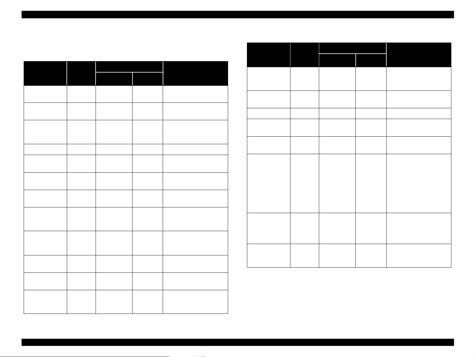
1.2.1 Local copy
1. Local copy
Table 1-1. Local Copy Specifications
Mode
Normal 300x300 Gray 360x360 Off Normal Bi-D Normal
B/W
Fine 600x300 Gray 720x720 On Variable Bi-D Normal
Normal 300x300
Color
Fine 600x600
Photo 600x600
Output mode = data from the scanner ASIC to the printer
Scan
res.
2. Enlargement: Default 100%
3. Brightness -2 (Darkest) ~ 0 (Default) ~ +2 (Lighte st) ( increments of
one)
4. Multiple Copies 1~20 copies (one page at a time when using the ADF)
5. Copy size Max. copy size 216 x 297mm (8.5 x 11.7inches)
Output
mode
Full
color
Full
color
Full
color
Print
res.
360x360 Off Normal Bi-D Normal
720x720 On Variable Bi-D Normal
720x720 On Vari able Uni-D Photo
Micro
Weave
Dot Size
Head
seq.
Enlargement 120, 141, 200%
Reduction 50, 70, 80, 93%
(not continuous)
(Top, bottom, and both sides
need 3mm margins)
Copy size protection A4/B5/A6 (A-size version)
Letter/Half Letter/5x8” (Letter
size version)
Media
Product Description Features 10
Page 11
EPSON Stylus Scan 2500 Revision A
6. Printing paper size Normal paper A4/Letter/A5/Executive
Half letter/B5/A6/Index card
5x8”/8 x10”/Post card/Legal
Photo paper A4/ Letter/4x5”/Post card
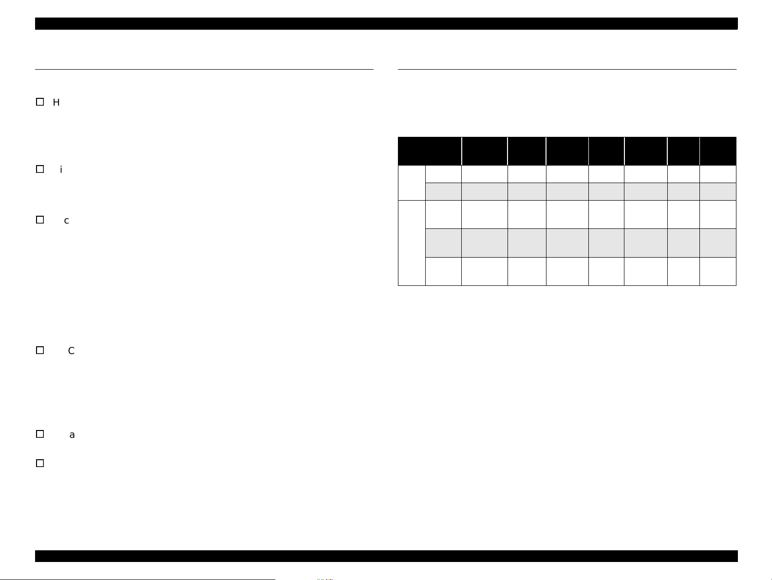
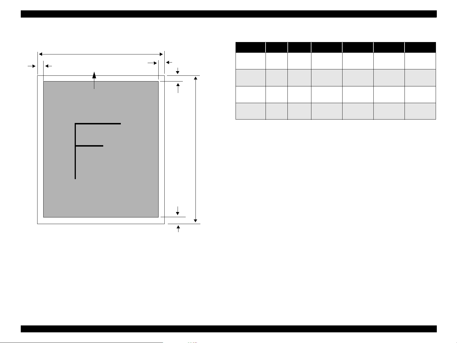
1.2.2 Scan area
LM
PW
Starting scan
position (1st bit)
Scanning Area
RM
TM
Document
edge (scale
edge)
PL
Document
size
A4 210mm 297mm
Letter 216mm 279mm
PW
(width)PL(length)
Table 1-2. Scan Area
LM
(left)
at least
3mm
at least
3mm
RM
(right)
at least
3mm
at least
3mm
TM
(top)
at least
3mm
at least
3mm
BM
(bottom)
at least
3mm
at least
3mm
BM
Figure 1-1. Scan Area
Product Description General Specifications 11
Page 12
EPSON Stylus Scan 2500 Revision A
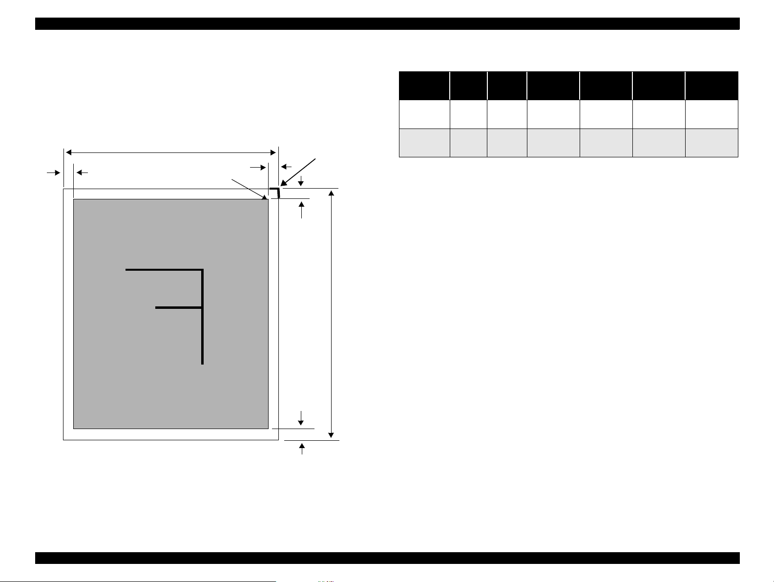
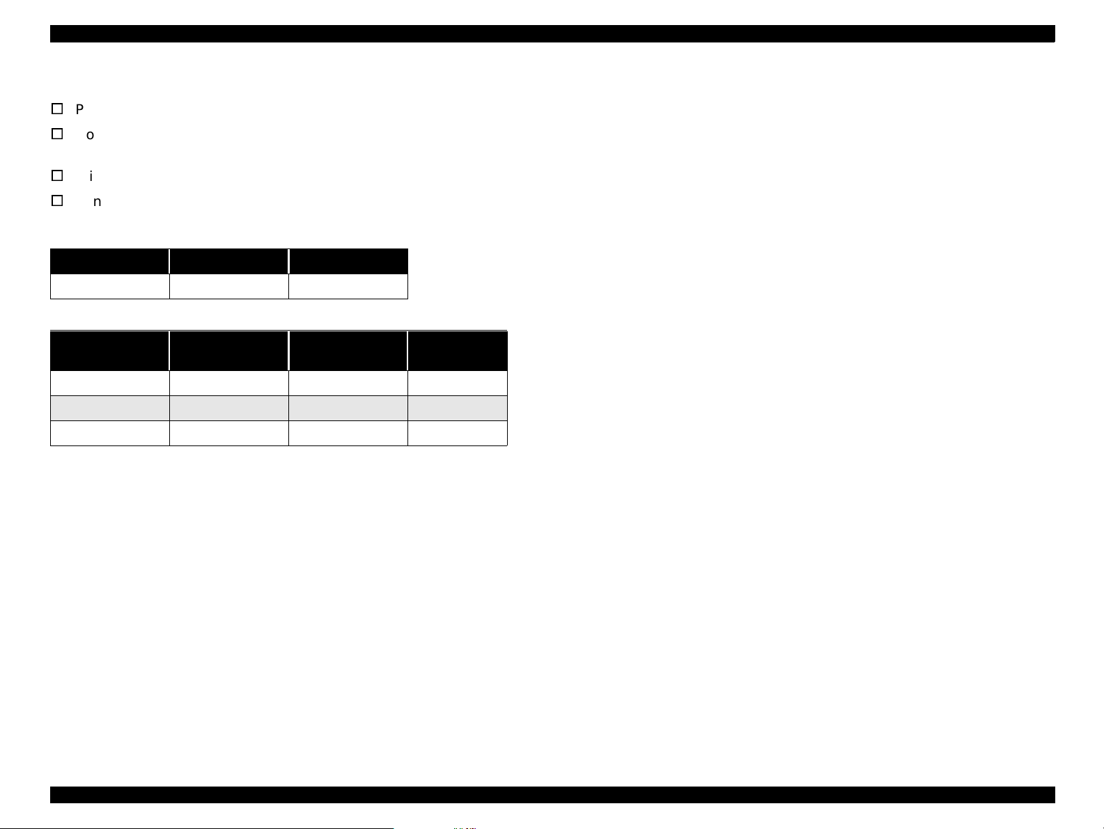
1.2.3 Print area
LM
Paper feed direction
PW
Printable Area
RM
TM
PL
Table 1-3. Print Area
Document PW PL LM RM TM BM
A4 210mm 297mm
Letter 216mm 279mm
B5 182mm 257mm
Legal 216mm 356mm
at least
3mm
at least
3mm
at least
3mm
at least
3mm
at least
3mm
at least
3mm
at least
3mm
at least
3mm
at least
3mm
at least
3mm
at least
3mm
at least
3mm
at least
3mm
at least
3mm
at least
3mm
at least
3mm
BM
Figure 1-2. Print Area
Product Description General Specifications 12
Page 13
EPSON Stylus Scan 2500 Revision A
1.2.4 Printing
V
Print method Drop On Demand ink jet
V
Nozzle configuration monochrome 144 nozzles (48 x 3 staggered)
color 48 nozzles each (cyan, m agenta, yellow)
V
Print direction Bi-direction with lo gi c seeking
V
Print speed & printable columns
Table 1-4. Character code
Character pitch Printable columns LQ speed
10 CPI (Pica) 80 200 CPS
Table 1-5. Raster Graphics mode
Horizontal
resolution
180 dpi 8.26 inch 1488 20 IPS
360 dpi 8.26 inch 2976 20 IPS
720 dpi 8.26 inch 5952 20 IPS
Printable area Available dots CR speed
1.2.5 Input data buffer
1.2.6 Control codes
ESC/P Raster
Epson Remote Command
1.2.7 Paper feed
1. Feeding method Friction feed with ASF
2. Line spacing 1/6 inch or programmable at 1/360
3. Paper path cut-sheet ASF (top enter, front out)
4. Feed speed 2.36 inch/sec. normal/ continuous
4.5 inch/sec. fast/continuous
64Kbytes
Product Description General Specifications 13
Page 14
EPSON Stylus Scan 2500 Revision A
1.2.8 Pape r
V
Cut-sheets
size: A4 210(W) x 297mm (L) (8.3 x 11.7”)
Letter 216 x 279mm (8.5 x 11.0”)
B5 182 x 257mm (7.2 x 10.1”)
Legal 216 x 356mm (8.5 x 14.0”)
Statement 139.7 x 215.9mm (5.5 x 8.5”)
Executive 184.2 x 266.7mm (7.25 x 10.5”)
Photo paper 101.6 x 152.4mm (4 x 6”)
thickness: 0.08~0.11mm (0.003~0.004”)
weight: 64g/m
quality: Exclusive paper, bond paper, PPC
V
OHP sheets, Glossy paper
size: A4 210(W) x 297mm (L) (8.3 x 11.7”)
thickness: 0.075~0.085mm (0.003~0.0033”)
NOTE: Transparency printing is only suppor ted at n ormal
temperature.
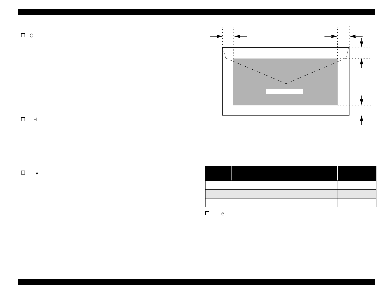
V
Envelopes
siz e: No.10 241(W) x 104.8mm (H) (9.5 x 4.125”)
thickness: 0.16~0.52mm (0.006~0.02”)
2
~90g/m2 (17~24lb.)
Letter 216 x 279mm (8.5 x 11.0”)
DL 220 x 110mm (8.7 x 4.3”)
C6 162 x 114mm (6.4 x 4.5”)
LM
Printable Area
Figure 1-3. Printable Area for Envelopes
Envelope printing is only supported at normal temperature.
Load long edge first.
Table 1-6. Envelope Margin
Size
#10 3 mm (0.12”) 28 mm (1.10”) 3 mm (0.12”) 14 mm (0.55”)
DL 3 mm (0.12”) 7 mm (0.28”) 3 mm (0.12”) 14 mm (0.55”)
C6 3 m m (0.12”) 3 mm (0.12”) 3 mm (0.12”) 14 mm (0.55”)
Left Margin
(min.)
Right Margin
(min.)
Top Margin
(min.)
Bottom Margin
RM
TM
BM
(min.)
weight: 45g/m
2
~75g/m2 (12~20lb.)
quality: Plain paper, bond paper, Air mail
V
Index cards
size: A6 index 105(W) x 148mm (L) (4.1 x 5.8”)
A5 index 148 x 210mm (5.8 x 8.3”)
5x8” index 127 x 203mm (5.0 x 8.0”)
10x8” index 254 x 203mm (10.0 x 8.0”)
thickness: less than 0.23mm (0.0091”)
Product Description General Specifications 14
Page 15
EPSON Stylus Scan 2500 Revision A
38.5
42.9
52.7
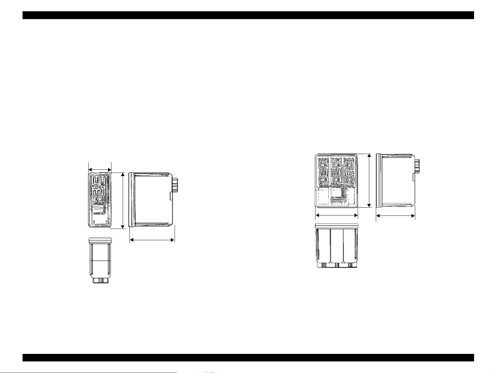
1.2.9 Ink
1. Ink cartridge (black)
Type: Exclusive cartridge
Color: Black
Print capacity: 900 pages/A4 (ISO/IEC 10561 Letter pattern 360dpi
Ink life: Two years from production date
Storage temperature: -20~40°C (storage, less than a month at 40°C)
-30~40°C (packing storage, less than month at 40°C)
-30~60°C (transit, within 120 hours at 60°C and
within a month at 40°)
Dimensions: 27.8 (W) x 52.7 (D) x 38.5mm (H)
27.8
52.7
2. Ink cartridge (color)
Type: Exclusive cartridge
Colors: Magenta, cyan, and yellow
Print capacity: 300 pages/A4 (360 dpi, 5% duty each color)
Ink life: Two years from production date
Storage temperature: -20~40°C (storage, less than a month at 40°C)
-30 ~40°C (packing storage, less than month at 40°C)
-30~60°C (transit, within 120 hours at 60°C and
within a month at 40°)
Dimensions: 42.9 (W) x 52.7 (D) x 38.5mm (H)
38.5
Figure 1-5. Color Ink Cartridge
Figure 1-4. Black Ink Cartridge
NOTE: Ink cartridges are consumable prod ucts and cannot by any
means be refilled.
Do not use cartridges that have passed their expiration d ate.
Ink will freeze at less than -4°C but can be used after thawing
for three hours at room temperature.
Product Description General Specifications 15
Page 16

EPSON Stylus Scan 2500 Revision A
1.3 Scanner
Product type Flat-bed color image scanner
Sub scan method Movement of scan head
Photoelectric device Color CCD line sensor
Max. scan area 8.5 x 11.7” (216 x 297mm)
Max. effective pixels 5100 x 7020 pixels (600dpi)
Scan resolution main = 600dpi
sub = 1200dpi
Output resolution 50~4800 dpi (1dpi increments)
(4800 dpi at 200% reaches the limitation of
maximum 16,368 pixels at 9600 dpi for main scan)
Scan speed (600dpi, Draft mode)
Color = 8.1msec/line
Monochrome (bi-level) = 2.7msec/line
Color separation By the CCD color filter
Command level ESC/I - B7
Zoom 50~200% (1% increments)
Line art Fixed threshold
TET
Digital halftoning AAS
Error diffusion three modes (A,B,C)
(Bi-level, Quad-level) Dither (resident) four modes (A,B,C,D)
Dither (user defined) two modes (A,B)
Interface USB and IEEE1284.4
Light source White cold cathode fluorescent lamp
Option TPU (for GT-7000)
ADF (for GT-7000)
Pixel depth 8 bits/pixel/color (input 12 bits/pixel/color,
output 8 bits/pixel/color)
Gamma correction CRT two levels (A,B)
PRINTER three levels (A,B,C)
User defined = one level
Color correction Impact-dot printer
Thermal printer
Ink-jet printer
CRT display
User defined
Brightness Seven levels
Product Description Scanner 16
Page 17

EPSON Stylus Scan 2500 Revision A
1.4 Common
1.4.1 Electrical specifications
Rated voltage AC 100~120V
AC 220~240V
Input voltage AC 100~120V
AC 220~240V ±10%
Rated current 0.7A (AC 100~120V
0.4A (AC 220~240V ±10% model)
Rated frequency range 50~60 Hz
Input frequency range 49.5~60.5 Hz
Power consumption Approx. 32W during Local-copy printing
Ω
Insulation resistance 10M
Dialectic strength AC 1.5kV, 1min
at 500V DC
(between AC line and chassis)
(between AC line and chassis)
±10%
±10% model)
1.4.2 Safety , EMC
Safety UL1950 (UL)
CSA C22.2 No. 950 (CSA)
EN60950 (VDE)
IEC950 (ROSTEST, PSB)
EMC FCC Part15 Subpart B Class B
CSA C108.8 Class B
AS/NZS3548 Class B
CISPR Pub22 Class B
CNS13438 Class B
CE Marking
Low voltage directive 73/23/EEC EN60950
EMC Directive 89/336/EEC EN55022 Class B
EN61000-3-2
EN61000-3-3
EN50082-1
IEC 801-2/801-3/801-4
Product Description Common 17
Page 18
EPSON Stylus Scan 2500 Revision A
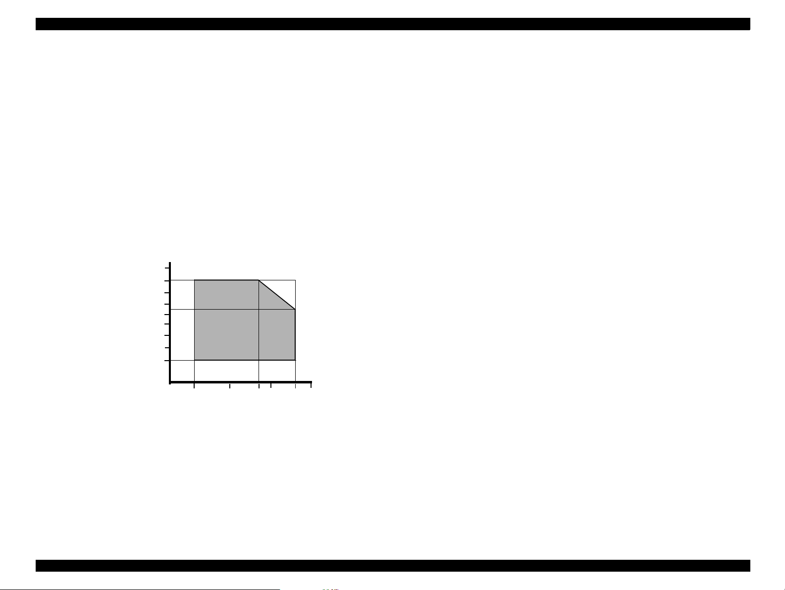
1.4.3 Environmental conditions
Temperature 10~35°C (operating, see figure below)
-20~60°C (non-operatin g, in packaging)
One month at 40°C
120 hours at 60°C
Humidity 20~80% RH (operating, without condensation, see
figure below)
5~85% RH (non-operating, in packaging without
condensation)
Resistance to shock 1 G, within one ms (operating)
2 G, within two ms (non-operating, in packaging)
Resistance to vibration 0.15G (operating)
0.50G (non-operating, in packaging)
90
80
70
60
Humidity (%)
50
40
30
20
10
1.4.4 Resistance to electric noise
Static electricity panel - 10kV
metal - 7kV/150pF, 150
Ω
1.4.5 Reliability
Total print volume 60,000 pages (A4, Letter)
Printhead life 4 billion dots/nozzle
Scan head MCBF 30,000 cycles
1.4.6 Acoustic noise
Level Approx. 46 dB (local copy with no ADF)
Approx. 50 dB (local copy with ADF)
(According to ISO7779)
10 27 30 35 4020
Temperature (°C)
Figure 1-6. Humidity and Temperature
Product Description Common 18
Page 19

EPSON Stylus Scan 2500 Revision A
1.5 Interfaces
This section is divided into printer and scanner interface specifications. See
the following section for printer interface details or see “Scanner interfaces”
on pag e22 for scanner interface details.
1.5.1 Printer Interface
PARALLEL
BUSY signal is set h i g h b e fore setting either -ERROR low or P E hig h , and held
high until all these signals return to th eir inactive state.
BUSY signal is at high level in the following cases:
T
During data entry (see data transmission timing)
T
When input data buffer is full
T
During -INIT signal is at low level or during hardware initialization
T
During printer error (see -ERROR signal)
T
When the parallel interface is not selected
ERROR signal is at low level when the printer is in one of the following states:
T
Printer hardware error (fatal error)
T
Paper-out error
T
Paper-jam error
T
Ink-out error
PE signal is at high level during paper-out error.
1. Specification
Packet Refer to the IEEE-1284 Standard for Data Delivery
and Logical Channels for IEEE Std. 1284.4 Interface
(Draft D1.50)
Refer to the IEEE-1284 specification
Signal level TTL compatible level (IEEE-1284 Level 1 device)
Data trans. timing Refer to the IEEE-1284 specification
2. Connector pin assignment and signals
Refer to the IEEE-1284 specification
3. Data transmission timing
Refer to the IEEE-1284 specification
4. Extensibility Request:
The printer responds affirmatively when the extensibility request values
are 00H or 04H, which mean
T
00H Request nibble mode reverse channel transfer
T
04H Request Device ID;
Return data using nibble mode reverse channel transfer
Device ID:
The printer sends the following device ID string when requested.
IEEE 1284.4 is enabled,
[00H][5EH]
MFG:EPSON;
CMD:ESCPL2,BDC,D4,SPC;
MDL:Stylus[SP]Scan[SP]2500;
CLS:PRINTER
DES:EPSON[SP]Stylus[SP]Scan[SP]2500;
Note: (1)[00H] denotes a hexadecimal value of zero
(2)MDL value depends on the EEPROM setting.
Transmission mode 8 bit parallel, IEEE-1284 compatibility/nibble mode
Synchronization Refer to the IEEE-1284 specification
Handshaking Refer to the IEEE-1284 specification
Product Description Interfaces 19
Page 20
EPSON Stylus Scan 2500 Revision A
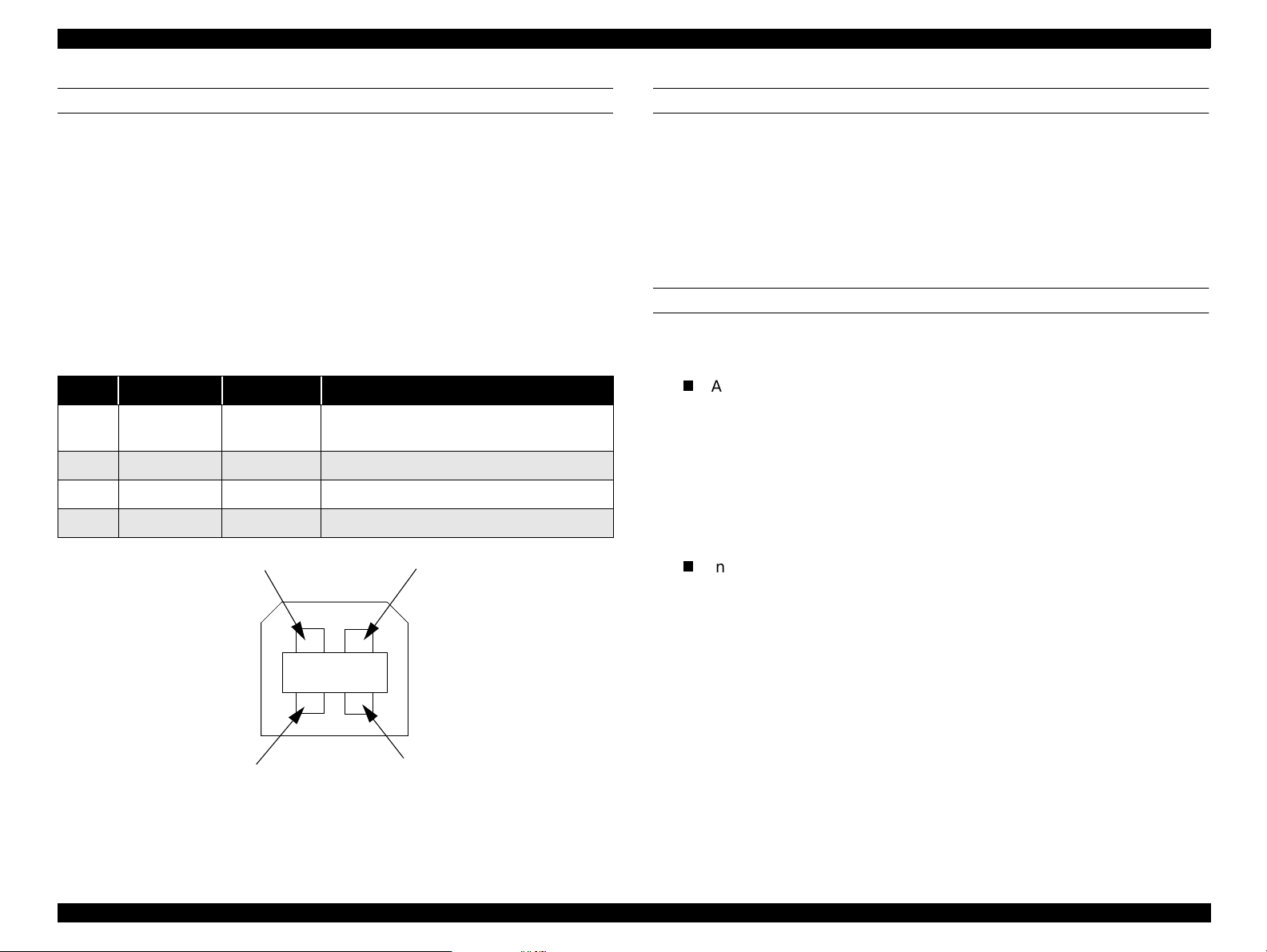
USB
Standard :based on
“Universal Serial Bus Specifications Revision 1.0”
“Universal Serial Bus Device Class Definition for
Printing Devices Version 1.0”
Bit rate :12Mbps (Full speed device)
Data encoding :NRZI
Adaptable connector :USB series B
Suggested cable length :2 meters
Table 1-7. USB Confi guration
Pin no. Signal name In/Out Description
1 VCC -
2 -Data bi-directional data
3 +Data bi-directional data, pull up to +3.3V via 1.5K Ω resistor
4 Ground - Cable ground
Pin #2
Cable power, max. power consumption is
100mA
Pin #1
PREVENTING DATA TRANSFER TIME-OUT OF HOSTS
Generally, hosts abandon data transfer to peripherals when a peripheral is
continuously in the busy state for dozens of seconds. To prevent hosts from
entering this kind of time-out period, the printer slows down the data
reception rate to around several bytes per minute, even if the printer is in the
busy state. This slowdown starts when the remaining open buffer area
decreases to several hundred bytes. The Stylus Scan enters a continuous
busy state if the input buffer becomes full.
INTERFACE SELECTION
The Stylus Scan has two built-in interfaces; the USB and parallel interfaces.
The interface in use is selected automatically.
T
Automatic selection
When the Stylus Scan is turned on, it initializes and then goes into an idle
state. During this idle period the printer scans the interfaces for incoming
data. The interface that receives data first is selected.
When the host stops transferring data and the printer is in the stand-by
state for a certain amount of time, the printer returns to the idle state. As
long as the host sends data or the printer interface is in the busy state, the
interface selection does not change.
T
Interface status and selection
When the parallel interface is not selected, the interface goes into the
busy state. When the printer initializes or returns to the idle state, the
parallel interface goes into the ready state. Be aware that an interrupt
signal such as the -INIT sig nal only takes affect on the parallel interface
when the parallel interface is selected.
Pin #4Pin #3
Figure 1-7. USB Pin Configuration
Product Description Interfaces 20
Page 21

EPSON Stylus Scan 2500 Revision A
IEEE1284.4 PROTOCOL
The packet protocol described by IEEE1284.4 standard allows a device to
carry on multiple exchanges or conversations which contain data and/or
control information with another device at the same time across a single
point-to-point link. The protocol is not, however, a device control language. It
does provide basic transport-level flow control and multiplexing services. The
multiplexed logical channels are independent of each other and blocking of
one has no effect on the others. The protocol operates over IEEE1284.
V
Automatic Selection
An initial state is compatible interface and starts IEEE1284.4
communication when magic strings (1284.4 synchronous commands)
are received.
V
On
An initial state is IEEE1284.4 communi c ation and data that received it
by the time it is able to take synchronization by magic string (1284.4
synchronous comm ands) is d i s carded.
V
Off
An initial state is compatible interface and never starts IEEE1284.4
communication even if magic strin g s (1284.4 synchronous
commands) are received .
1.5.2 Scanner interfaces
PARALLEL
1. Specification
Transmission mode 8 bit parallel, IEEE-1284 compatibility/nibble mode
Synchronization Refer to the IEEE-1284 specification
Handshaking Refer to the IEEE-1284 specification
Packet Refer to the IEEE-1284 Standard for Data Delivery
and Logical Channels for IEEE Std. 1284.4 Interface
(Draft D1.50)
Refer to the IEEE-1284 specification
Signal level TTL compatible level (IEEE-1284 Level 1 device)
Data trans. timing Refer to the IEEE-1284 specification
2. Connector pin assignment and signals
Refer to the IEEE-1284 specification
3. Data transmission timing
Refer to the IEEE-1284 specification
Product Description Interfaces 21
Page 22
EPSON Stylus Scan 2500 Revision A
USB
Requests
The scanner must support almost all standard device requests. The
Any items not included in this manual and/or the user’s guide shall be in
scanner does not support vendor specific requests.
compliance with the Universal Serial Bus Specification Revision 1.0
Configuration - the scanner supports the following configurations
Table 1-8. Scanner Configuration for USB
Element Description
Full Speed Mode (12Mbit/s)
Class: Vendor-specific
Subclass: Vendor-sp ecific
Device
Configuration
Protocol: Vendor-specific
Vendor ID: 0x04B8 (Seiko Epson Corp.)
Product ID: 0x0106
Number of possible configurations: 1
Num ber of int e rfaces supported by th i s c onfiguration: 1
Characteristi cs : Self-powered ( Rem ote w ake- up feature not
supported)
Max. power consumption from VBUS: 2mA (5V)
No alternate setting
Number of endpoints used by this interface (excluding
Interface
Endpoint
String Descriptor
endpoint 0):2
Class: Vendor specif ic
Subclass: Vendor speci fic
Protocol: Vendor specific
Bulk IN transfer
Max. da ta tran sfer size : 6 4 byte s
Bulk OUT transfer
Max. da ta tran sfer size : 6 4 byte s
Language ID: English, US
1: iManufacturer “EPSON”
2: iProduct “Scanner Stylus Scan 2500”
Product Description Interfaces 22
Page 23

EPSON Stylus Scan 2500 Revision A
1.6 Control Panel
Load/
Print out Size
Eject
Cleaner
Scan
button
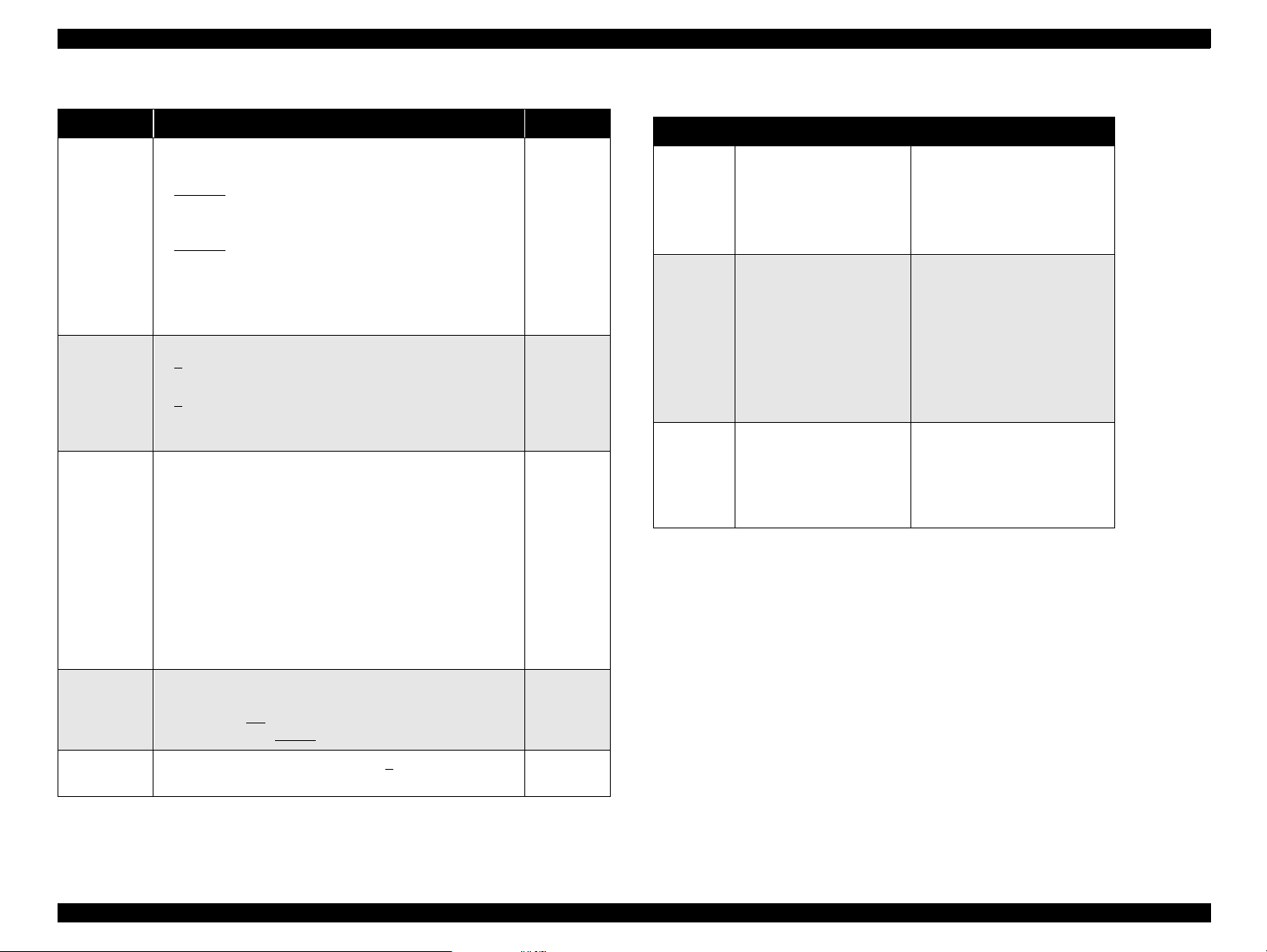
1.6.1 Buttons
Table 1-9. Button functions
Button Function
Load/Eject
(pushed within
two* seconds)
Load/Eject
(pushed for two*
seconds)
Cleaning
(pushed for two*
seconds)
Cleaning
(pushed within
two* seconds)
• Loads or ejects paper
• I f the carriage is at the ink car tridge in stallation p osition,
returns the carriage back to the home position.
• Starts the ink cartridge replacement sequence (not
available during printing.
Shifts the carria ge to the ink cartridg e replacement
position.
• Starts the printhead cleaning cycle.
• If the printer is in the “Ink Low” or “Ink Out” or “No Ink
Cartridge” condition, starts the ink cartridge replacement
sequence.
• If the carriage is at the ink cartridge replacement position,
returns the carriage f ro m the in k cartrid ge re placement
position to the home position.
button
Darker/
Lighter
Reduce/
Enlarge
Quality
button
Copies
LCD Panel
Hold for
menu
Return
Item
B&W/Color
button
Figure 1-8. Control Panel
Button Function
Load/Eject
Load/Eject
Cleaning
Button Function
Load/Eject Resets the real-time counter (power-off time) in EEPROM
Cleaning
(hold for ten
seconds)
Copy
button
Stop/Clear
button
Error
indicator
S
Operate
indicator
Table 1-10. Power-on functions
Prints a sta tus sheet that includes fi rmware ver s ion, ink
counter, and nozzle check patterns.
Enters the special-settings mode (see table below), which
+
remains active for three seconds. If neither the Load/Eject
nor Cleaning button is pushed in that three seconds, normal
initialization begins.
Table 1-11. Special settings mode
Resets the waste ink overflow counter
* The user’s guide states three seconds.
Product Description Control Panel 23
Page 24
EPSON Stylus Scan 2500 Revision A
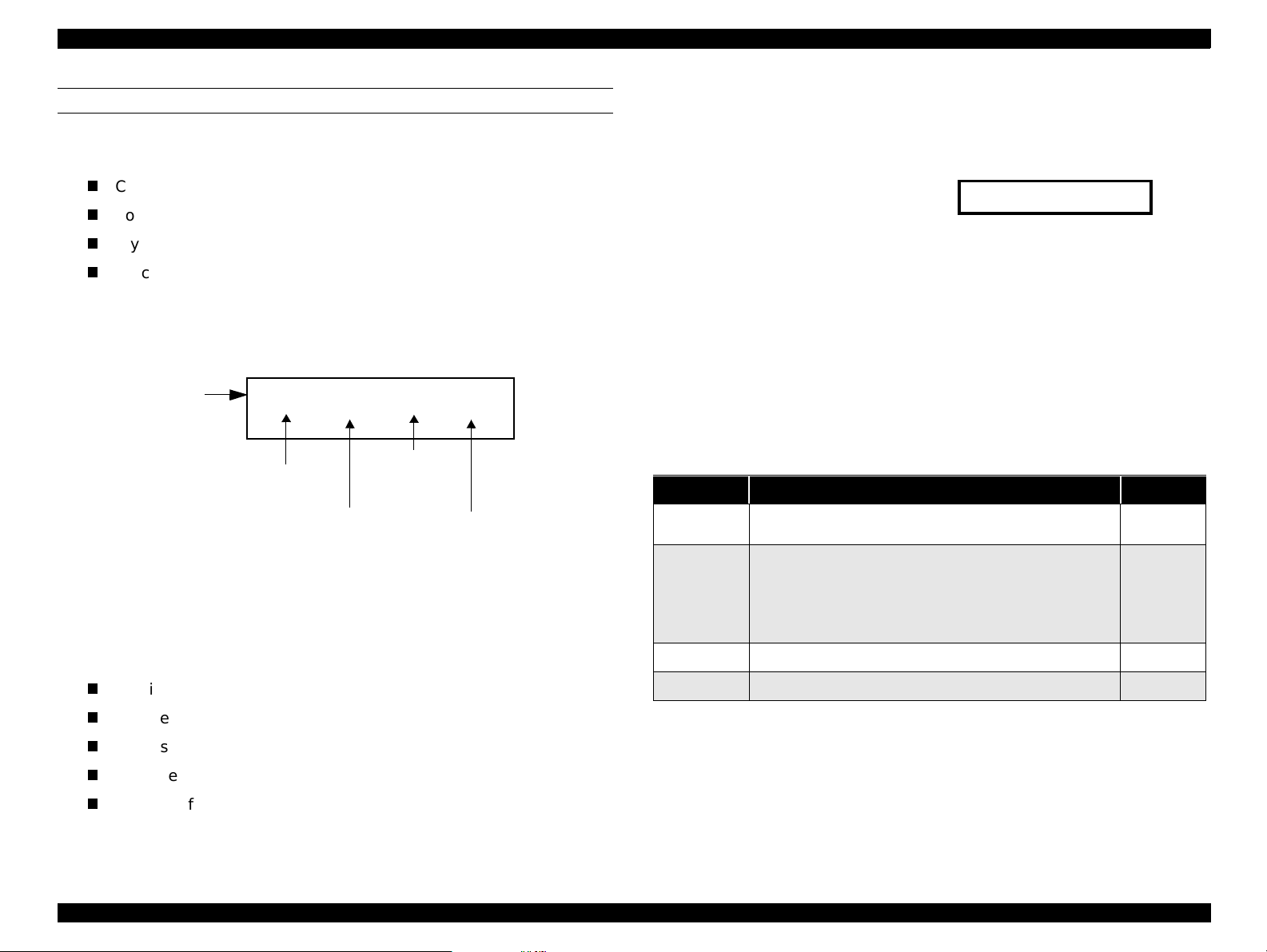
Warm up
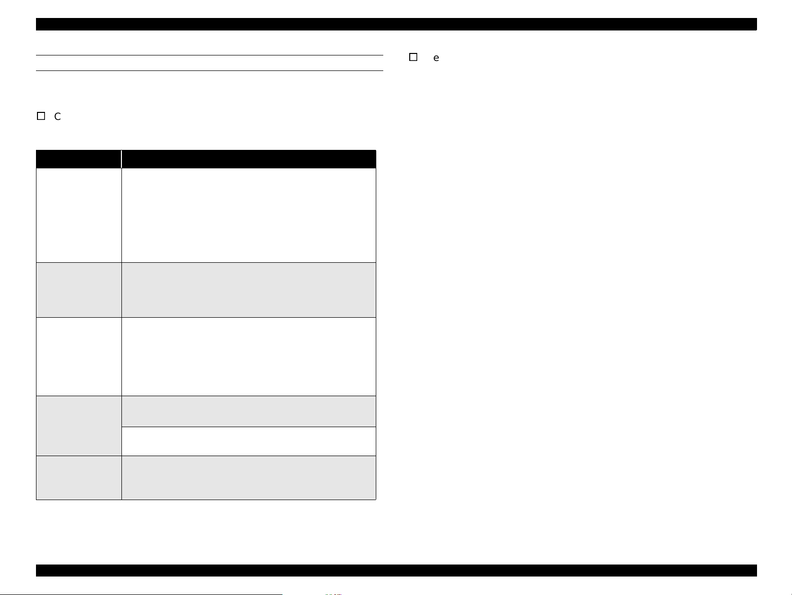
COPY BUTTON
Before performing a local-copy operation, you should understand how the
LCD and control panel buttons work. The LCD displays:
Copy status
Copy settings
Stylus Scan error messages and maintenance status
Miscellaneous settings not directly related to copying
1. Copy status
While waiting for a copy job, the current copy settings are displayed.
Example: (default)
LCD
Button
s
100% B&W Normal 1
Reduce/
Quality
Enlarge
B&W/
Color
Number of
copies
Figure 1-9. LCD and Button Relationship
2. Copy settings
Allows you to make the following copy settings.
Quality
3. Status
Displays the current Stylus Scan condition.
Example:
Scanner lamp is warming up
4. Miscellaneous settings
Allows users to print or change the following
Demo pattern
Status sheet
Bottom margin
Paper size category (metric or US)
Language code
Set factory default
Table 1-12. Copy button functions
Button Function Notes
Operate
Stop/Clear
Copy
B&W/Color
• Sets Local Copy Mode as the default; same as
printer reset.
• Stops the current copy job and ejects the paper
during copying.
• Clears number of copies setting (returns to “1”)
• Clears settings and returns settings to their default
values.
• Starts copying (default =
• Selects Color copy or Black & white copy
B & W 100% Normal 1)
Reduce/Enlarge
Paper size
Brightness
Number of copies
Product Description Control Panel 24
Page 25
EPSON Stylus Scan 2500 Revision A
Table 1-12. Copy button functions (cont.)
Button Function Notes
Sets copy quality
•B&W
Normal
Fine
Quality
Multiple
copies
Enlarge/
Reduce
Printout Size
• Color
Normal
Fine
Photo
Note: When Photo is s electe d, the LCD displ ays “ Load
Photo Paper”.
•B&W
1
-20
• Color
1
-20
Increments by “1”, and increment speed increases if
held for more than one second.
• Selects reduce or enlarge
• Default = 100%
• First press = LED shows current status
• Multiple presses (within 5 sec.s) = moves up one
setting each time
Example
First time = Enlarge/Reduce LED onl y (100%) activated
(default)
Second or more time = cycles through the following.
93% > 80% > 70% > 50%
200% > 141% > 120%
Sets the size of the printed paper during Local Copy
mode;
A size area = A4
Letter size area = Letter
/B5/A6
/Half Letter /5x8”
Resets to 1
if Stop/
Clear
button is
pressed.
Table 1-13. Settings Menu
Button Function LCD
Hold Quality + B&W buttons
Quality
B&W/
Color
Copies
+/-
Copy
Change modes
Copy<-> Settings Menu
Change menu in
Settings Menu mode
Executes menu or
selects item
for three seconds
Menu Mode
After two seconds
BottomMargin:14/3mm
Cycles through the menus
below:
BottomMargin:14/3mm
PaperSize: Metric/US
Lang: Eng Ger Fr Ital Span
Set Factory Default
Status Sheet Print
Lang: Eng Ger Fr Ital Span
Press copy to change to next
Lang: Eng Ger Fr Ital Span
Port
Port
Port
Brightness
Sets the brightness level from -2>0
of “1”.
>+2 in increments
Product Description Control Panel 25
Page 26
EPSON Stylus Scan 2500 Revision A
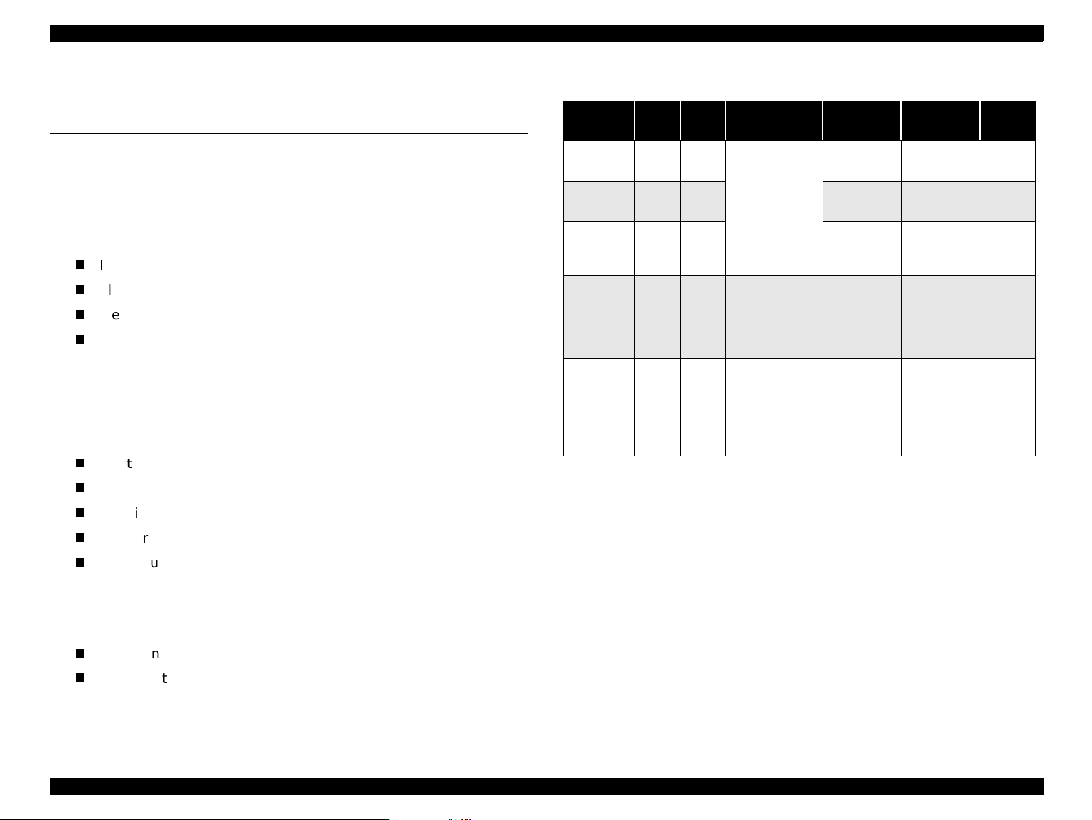
1.6.2 Indicators and LCD Display
Table 1-14. LCD display and LED indicators
Scanner
Status
Scanner fatal
error
Printer fatal
error
Maintenance
reque s t (waste
ink pads full)
ADF paper jam S - On ADF Jam
Printer paper
jam
ADF cover
open
Printer paper
out
Black Ink end/
No ink
cartridge
Color Ink end/
No ink
cartridge
Ink ca r t r idge
change mode
Maintenance
cover open
Black ink level
low
Printer
Copy
S - On Scanner Error
P - On Printer Error
P - On Call Service
P - Flashing Printer Jam
S - Flashing ADF Cover Open
P - Flashing Printer Paper Out
P - Flashing Black Ink Out
P - Flashing Color Ink Out
P Flashing - Replace Cartridge
S Flashing - Maint. Cover Open
P- -
Indicators
Display message
Operate Error
Black Ink Low (displays
alternately with regular
message)
Table 1-14. LCD display and LED indicators (cont.)
Scanner
Status
Color In k level
low
Scanner lamp
warming up
Ink ch arging P Flashing - Warm Up
Scanning S F la s hing -
Printing P Flashing -
Copying C Flashing -
Power on (all) On -
Initialize
EEPROM and
reset timer IC
This order of items in this table is from high to low priority.
“-” = no change/does not matter
Printer
Copy
P- -
S Flashing - Warm Up
P - - EEPROM Reset
Indicators
Display message
Operate Error
Color Ink Low (displays
alternately with regular
message)
Scanning [xxx]
(xxx=I/F)
Printing [xxx]
(xxx=I/F)
Following messages
alternate:
A message = (current
copy settings)
B message = Now
Copying x/y (x=current
document number, y =
total number of copies)
Power on (for two
seconds and then
changes to Copy Mode
(default))
Product Description Control Panel 26
Page 27
EPSON Stylus Scan 2500 Revision A
1.6.3 Initialization
PRINTER INITIALIZATION
There are three initialization methods.
1. Power-on (hardware) initialization
The printer initializes when turned on or when it recognizes the cold-reset
command (remote RS command).
When the printer initializes, the following actions are performed.
Initialize printer mechanism
Clear input data buffer
Clear print buffer
Set default values
2. Operator initialization
The printer initializes when turned on within ten seconds of being turned
off, or when the printer recognizes the -INIT signal (negative pulse) from
the parallel interface.
When the printer initializes, the following actions are performed.
Cap the printhead
Operation
Power on Valid Valid
Panel
Reset
Initialize
by
command
STOP Valid -
CLEAR - Valid
Operat
Valid Valid
Valid Valid
StandbyController
ing
Table 1-15. Initialization
Scanner
process
Set the local
copy setting to
default
• Stop
copying
•Setting
remains as
is
•Setting
mode:
default
• Copy mode:
Multi-copies
volume 1
process
H/W
initialization
Controller
initialization
S/W
initialization
Cancel Eject paper
Printer
process
H/W
initialization
Panel
initialization
S/W
initialization
Restart
-
-
-
Copy
button
Eject paper
Clear input data buffer
Clear print buffer
Set default values
3. Software initialization
The ESC@ command also initializes the printer.
When the printer initializes, the following actions are performed.
Clear print buffer
Set default values
Product Description Control Panel 27
Page 28
EPSON Stylus Scan 2500 Revision A
SCANNER INITIALIZATION
There are three initialization methods.
1. Hardware initialization
The scanner initializes when turned on.
When the scanner initializes, the following actions are performed.
Initialize scanner mechanism
Clear input/output data buffer
Set default values
2. Operator initialization
The scanner initializes when it recognizes the -INIT signal (negative pulse)
from the parallel interface.
When the scanner initializes, the following actions are performed.
Clear input/output data buffer
Set default values
3. Software initialization
The ESC@ command also initializes the scanner.
When the scanner initializes, the following actions are performed.
1.7 Settings Menu
Enter the settings menu mode by holding down the Quality and B&W/Color
buttons. Settings are saved when the power is turned off.
Table 1-16. Settings Menu
Button Function LCD
Hold Quality + B&W buttons for three
Quality
B&W/
Color
Copies
+/-
Copy
Change modes
Copy<-> Settings Menu
Change menu in
Settings Menu mode
Executes menu or
selects item
seconds
Menu Mode
After two seconds
BottomMargin:14/3mm
Cycles through the menus below:
BottomMargin:14/3mm
PaperSize:Metric/US
Lang:Eng Ger Fr Ital Span Port
Set Factory Default
Status Sheet Print
Lang: Eng Ger Fr Ital Span Port
Press copy to change to next
Lang: Ger Fr Ital Span Port Eng
Clear input/output data buffer
Set default values
Product Description Settings Menu 28
Page 29
EPSON Stylus Scan 2500 Revision A
MENUS
1. Bottom Margin
Determines the default bottom margin of 14mm or 3mm.
2. Paper Size category
Determines which paper size category is enabled; metric or US
Metric = A4/B5/A6
US = Letter/Half Letter/5x8”
3. Language
Determines which language is us ed to display LC D mes sa ges;
English/German/French/Italian/Spanish /P o rtuguese
4. Set Factory Default
Determines parameters for factory default settings.
Factory default settings:
Copy mode = Refer to “Buttons” on pag e24
Settings Menu mode = 14mm bottom margin
The Paper Size and Language parameters are saved as defaults when
power is turned off.
5. Status sheet
Prints the following settings:
Bottom margin
Paper size category
Language
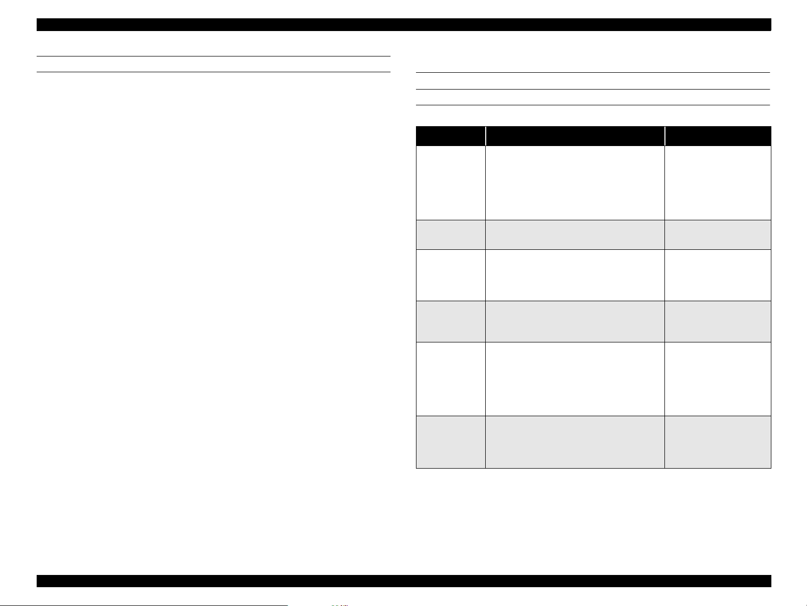
1.8 Stylus Scan Errors
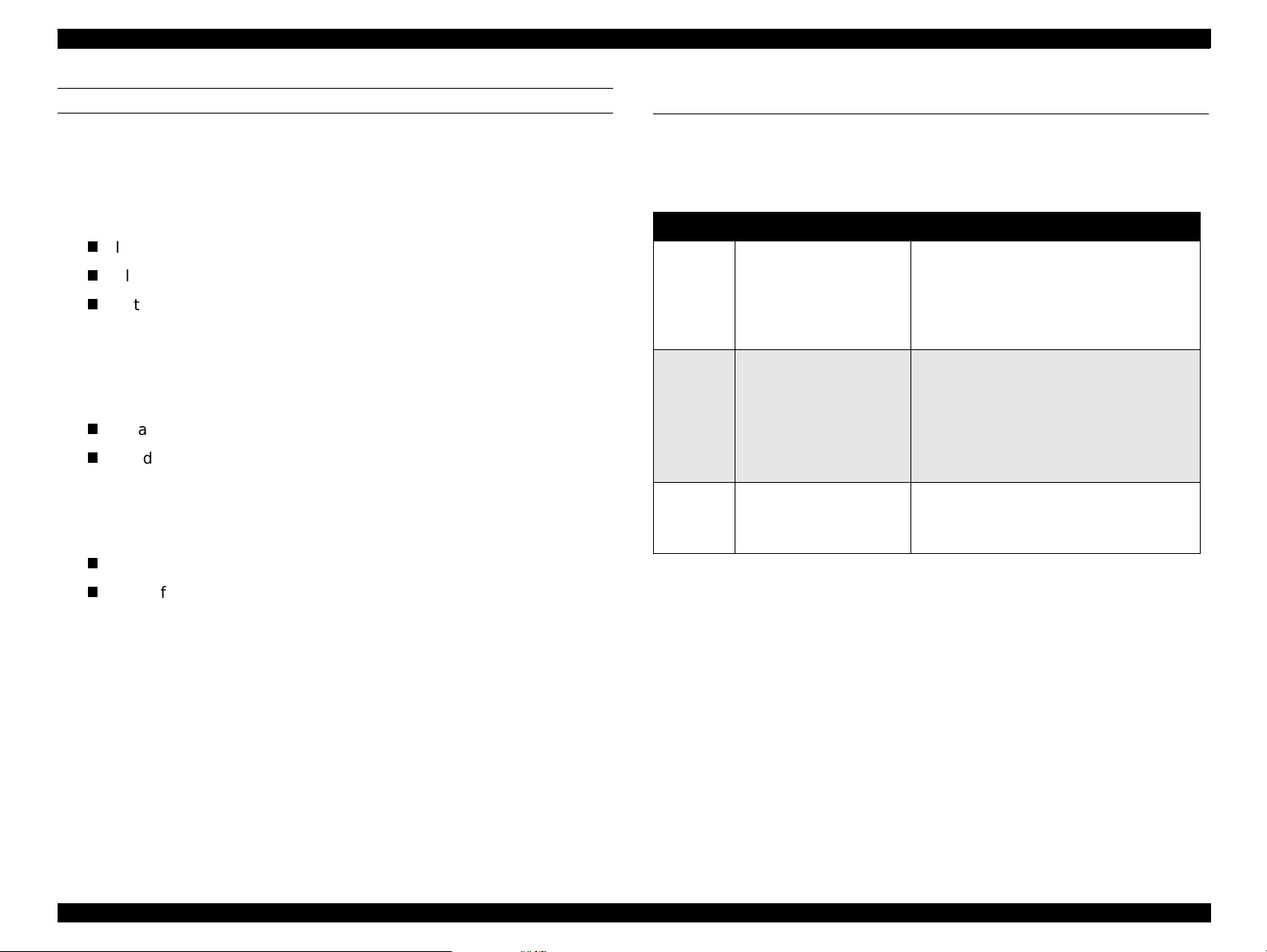
PRINTER-SPECIFIC ERRORS
Table 1-17. Printer-SPECIFIC errors
Error Cause Solution
When one or more ink cartridges are
almost empty, the printer enters the
Ink out
Paper out
Paper jam
No ink
cartridge
Call Service
low-ink state and continues printing.
When the cartridge is completely empty,
the printer indicates an ink-out error and
stops printing.
If the printer f ails t o prop erly l oad paper ,
it indicates a paper-out error.
If the printer fails to prope rly eject pap er,
it indicates a paper jam.
If the printer detects that one of the ink
cartridges i s not installe d, it indicates a
no-ink-cartridge error.
When the total amount of waste ink
reaches the limit, the printer indicates a
maintenance request and stops printing.
Install a new ink
cartridge.
Load paper and press
the Load/Eject button.
Press the Load/Eject
button. If this does not
clear the error, remove
the paper by hand.
Install a new ink
cartridge.
Replace the waste ink
pads and reset the
waste ink counter with
the adjustment
program. See Chapter
5 for details.
Turn off the Stylus
Fatal error
A carriage control or CG access error
has occurred.
Scan and turn it back
on. If the error does not
clear, service.
NOTE: Do not re-install used ink cartridges. Doing so confuses the
ink-level detection function and may cause a serious problem
in the printhead.
Product Description Stylus Scan Errors 29
Page 30
EPSON Stylus Scan 2500 Revision A
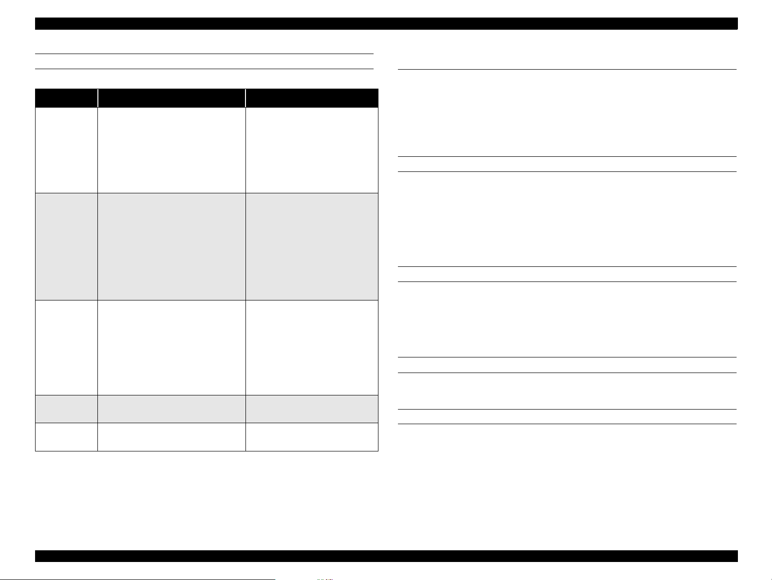
SCANNER-SPECIFIC ERRORS
Table 1-18. Scanner-SPECIFIC errors
Error Cause Solution
Fatal error
ADF paper
jam
Command
error
ADF cover
open
Maintenance
cover open
• The lamp is broken.
• Stylus Scan turned on before
the tran sportation screw w as
removed.
• System breakdown.
ADF fails to eject the document.
Unidentified command detected.
(Disposition)
The scanner sent a NACK signal
and is waiting for the next
command. If an incorrect
command or parameter is
received, it is disregarded and the
previous value is maintained.
ADF cover open Close the cover.
Maintenance cover open Close the cover.
Turn off the Stylus Scan and
turn it back on. If the error does
not clear, service.
(Disposition)
Turn off the lamp and stop
operation. Set bit 7 of the
status byte.
After removing the document,
turn the Stylus Scan off and
back on, or send the ESC @
command.
Parallel I/F init: active pulse
(Disposition)
Turn off the lamp and stop
operation. Set bit 7 of the
status byte.
Send a correct command to
clea r th e e rror.
1.9 Options
The optional Auto Document Feeder and optional Transparency Unit
designed for use with the GT-7000 scanner may also be used with the EPSON
Stylus Scan 2500 under the following restrictions.
1.9.1 Local Copy
ADF
If a document is loaded in the ADF tray, the Stylus Scan loads and scans that
document.
If a document remains on the document glass, a copy is not produced
normally.
Even if multiple copies are selected, the Stylus Scan ignores this setting and
produces only one copy per document sheet.
TPU
The TPU cannot be used in Local Copy mode. The Stylus Scan ignores the
TPU in this mode.
1.9.2 Scanning
ADF
Same as the GT-7000.
TPU
If the Stylus Scan receives transparency scanning commands, it will turn on
the TPU lamp and scan the transparency after the warm-up period. The Stylus
Scan ignores the ADF in this mode. After scanning, the TPU lamp remains on
until the TPU is turned off or until the Stylus Scan receives reflective
document scanning commands.
If the Stylus Scan receives reflective document scanning commands, it will
scan the document normally.
Product Description Options 30
Page 31

EPSON Stylus Scan 2500 Revision A
1.10 Physical Characteristics
1.10.1 Dimensio ns
212 x 517 x 413mm (HWD)
(not including, extended parts, rubber parts, and the ASF projection)
1.10.2 Weigh t
Approximately 12Kg
Product Description Physical Characteristics 31
Page 32

EPSON Stylus Scan 2500 Revision A
Product Description Physical Characteristics 32
Page 33

OPERATING PRINCIPLES
CHAPTER
2
Page 34

EPSON Stylus Scan 2500 Revision A
2.1 General
The main components of the EPSON Stylus Scan 2500 are the printer
mechanism, scanner mechanism, and the following circuit boards
Main: B102 Main Board
Power Supply: B102 PSB/PSE Board
Panel: B102 PNL Board
2.2 Printer Mechanism Operation
Like previous EPSON Ink Jet printers such as the Stylus Color 740, the
printer mechanism of the EPSON Stylus Scan 2500 does not have an
exclusive mechanism to switch from paper feeding to pumping and back.
Ins t e a d , thi s cont r o l is done by th e r otatio n a l direct i o n o f t he paper feed/
pump motor and also depends on the position of the carriage.
The printhead combines the black and CMY heads in on e unit. The
following indicate the nozzle configurations of these 3 models.
Black Nozzles: 144 noz zles (120 dpi x 3 rows in staggered)
CMY Nozzles: 48 nozzles/colors (120 dpi x 1 row)
Motor Types and Corresponding Functions
Motor Type Function
CR Motor Stepping Used to drive the carriage. page 38
• Drives the ASF to feed paper into
paper path
• Drives paper feed rollers at variable
PF Mot or Stepping
speeds
• Drives the CR Lock lever (as
described on page44)
• Drives pump unit to absorb ink
For det a ils
see
page 40
Figure 2-1 in the in the right column shows the outline of the printer
mechanism.
Operating Principles General 34
Page 35

EPSON Stylus Scan 2500 Revision A
PF motor
pinion
Intermittent
gear
PF Motor
Flushing section
Star wheel
Disengage flag
Black I/C sensor
CMY I/C sensor
Carriage unit
Printhead
(one unit)
Timing belt
Cap unit
Pump unit
CR guide shaft
Disengage
flag
PF roller
PG lever
73.6 Gear/Precision Gear
ASF
sensor
Detector
wheel
Loading
shaft
Loading
rollers
PE sensor
Carriage HP
sensor flag
Carriage HP
sensor
CR Motor
2.2.1 Printing Mechanism
The basic principles of the printhead are the same as previous models; DropOn-Demand type MACH head method.
You need to manually input the drive-voltage code (printed on top of the
printhead) for the multi-layer piezo electric element. Input this value every
time you replace the printhead, MAIN board, or printer mechanism.
The main parts of the printh e ad a nd carriage are described below.
PZT
PZT is an abbrevi ation of P iez o Electric Element. The print sign al is
sent from the MAIN board to the PZT via the driver circuit on the
printhead
the ink stored in the cavity out through the nozzle. This process is
described in more detail on the next page.
Ink c avi ty
Ink flows from the ink cartridge, through the filter, and to the ink
cavity where it is stored until one of the PZT units forces it out through
the nozzles.
Nozzle Plate
The bott om surface of the printhead which contains nozzle ho l e s to
direct ejected ink toward the paper below. See the next page.
Filter
When the ink cartridge is installed, if any dirt or dust around the
cartridge needles i s absorb ed into the inside of the printhead, there i s
a large possibility that the nozzles will clog. Clogged nozzles can be
detected by alignment failure and dot-missing problems. To prevent
these k inds of pr oblems, a filter is se t below the cartridge needle and
ink flows through the filter on its way to the ink cavity.
unit. Then, the appropriate PZT squeezes the cavity, forcing
Figure 2-1. Printer Mechanism Block Diagram
Operating Principles Printer Mechanism Operation 35
Page 36

EPSON Stylus Scan 2500 Revision A
Nozzle selector
Board
Ink Out
sensor
actuators
Needle
Ink cartridge
PZT
(Piezo)
unit
Filter
Nozzle
plate
Figure 2-2.
Ink Out sensor actuators (x2)
The Ink Out sensors (x2) detects whether or not an ink cartridge is
installed according to the position of the Ink Out sensor actuator.
When a cartridge is installed, the actuator is pushed down, which
turns the shaft that is connected to the actuator. The flag at the other
end of the shaft activates the Ink Out sensor when the cartridge is fully
in place.
See the next page for more details on the nozzle selector board and the ink
ejecting process.
Printhead
Ink cavity
Sectional Drawing
Operating Principles Printer Mechanism Operation 36
Page 37

EPSON Stylus Scan 2500 Revision A
2.2.2 Printing Process
The following figures show sectional drawings of the printhead in the normal
and ejecting states.
1. Normal State:
When no print signal is output, the PZT is in the normal, standby, state.
Ink course
Piezo unit
Nozzles
Figure 2-3. Printhead Normal State
Cavity
Nozzle plate
surface
2. Ejecting State:
When a print signal is sent from the MAIN board, the IC (Nozzle Selector)
located on the printhead unit receives the data in 1-byte units. The Nozzle
Selector then sends the voltage signal on to the appropriate PZT. Due to
the physical properties of the PZT, electrical signals cause the PZT to
change shape. When the PZT changes shape, it squeezes the ink cavity,
ejecting ink out through the nozzles.
Figure 2-4. Printhead Ejecting State
Operating Principles Printer Mechanism Operation 37
Page 38

EPSON Stylus Scan 2500 Revision A
Rotor
1
2
3
4
A
/A
B
/B
2.2.3 Carriage Mechanism and Motor
The carriage mechani sm moves the carriage back an d forth according to
the drive from the carriage motor. See Figure 2-6 on the next page.
The carriage motor is a 4-phase, 200-pole, stepping motor and is driven
by 2-2 phase, 1-2 phase, Double 1-2 phase, 2-Double 1-2 phase, and 4Double 1-2 phase drives. This stepping motor allows the carriage to move
freely to fixed positions where necessary operations such as ink
absorption can be performed. The following tables show carriage the
motor specifications and motor controls.
Carriage Mo to r Sp ecifications
Items Description
Motor type 4-Phase/200-pole Stepping motor
Drive voltage Range 42VDC ± 5%
Internal coil resistance
Control method Bi-Polar Drive
Phase drive 2-2, 1-2, 2-Double 1-2, and 4-Double 1-2
7.8 Ohms ± 10%(per phase in 25 °C
environment)
Phase drive
CR Motor Control for Each Mode
Printing mode
High Speed Skip 340 4080
Normal Printing 200 2400
Capping 80 960
Wiping 40 480
Cap (Valve
Release)
Withdrawal of cap 5 60
Drive Speed
[CPS]
20 240
Drive frequency
[PPS]
Drive method
Double1-2, 2-2,1-2
phase drive*
Double 1-2, 2-2 phase
drive
2-Double 1-2, 2-2 phase
drive
2-Double 1-2, 2-2 phase
drive
4-Double 1-2, 2-2 phase
drive
4-Double 1-2, 2-2 phase
drive
Phase Drive inch/pulse mm/pulse
2-2 1/120 0.212
1-2 1/240 0.106
Double 1-2 1/480 0.053
2-Double 1-2 1/960 0.026
4-Double 1-2 1/1920 0.013
Figure 2-5. CR Motor Internal Circuit Diagram
Operating Principles Printer Mechanism Operation 38
Page 39

EPSON Stylus Scan 2500 Revision A
PLATEN GAP LEVER
Carriage
motor
Rear (thick
paper) position
Parallelism
adjust
lever
Paper feed
roller
Paper eject
rollers
Timing
belt
Paper guide
(front)
Home position
sensor
Carriage
unit
Forward
(normal)
position
Platen Gap
lever
Figure 2-6. Carriage Mechanism with platen gap lever (Top view)
As shown in Figure 2-6, the Platen Gap lever can be moved forward or
back to adjust for the thickness of the paper. The PG lever is connected to
the carriage guide shaft, which raises or lowers the carriage depending on
the PG lever position. The nozzle surface remains parallel to the p aper in
either position thanks to a tilt adjustment mechanism. Also, the two
parallelism-adjustment levers, one mounted on each side of the carriage
guide shaft, adjust the parallelism between the platen and shaft when the
shaft is installed in the factory. This precise adjustment is necessary to
make sure the gap between the platen surface and the printhead surface
is 1.04 mm in the normal position or 1.74 mm in the thick-paper position.
Operating Principles Printer Mechanism Operation 39
Page 40

EPSON Stylus Scan 2500 Revision A
Rotor
1
2
3
4
A
/A
B
/B
2.2.4 Paper Feeding Mechanism
The pape r fee ding proce s s begin s at the ASF, conti nu es th r ou gh th e PF
roller, and ends at the paper eject roller (and star-wheel gea r).
The ASF unit, which is common with the Stylus C OLOR 740 printers, is
driven by the PF motor (stepping motor). Torque sent from this motor
switches between the ASF unit and pump/PF roller depending on the
position of the disengage lever (described later).
In the EPSON Stylus Scan 2500, a four-phase hybr id typ e pulse motor is
used in the PF motor as a motive pow e r of the paper mechanism. The
torque is sent at 2-Double 1-2, Double 1-2, 1-2, and 2-2 phase drives. This
motor drives the paper-feeding mechanism as well as the pump
mech anis m wh ic h i s ne ce ss ar y f or pr int h ead cle an in g. By usi ng th is pul s e
motor, it becomes possible to use variable drive levels for many
purposes, such as paper feed, slight paper feed, and high or low speed
absorption of pump operations. The following table shows PF motor
specificat ions.
Figure 2-7. PF Motor Internal Circuit Diagram
Motor Control for Each Mode
PF Motor Specifications
Item Description
Motor type 4-phase/200-pole Stepping motor
Drive voltage 42VDC ± 5%
Coil Resistance
Control method Bi-Polar Drive
Phase drive 1-2, 2-2, Double 1-2, 2-Double 1-2
7.8 Ohms ± 10%(per 1 phase under 25°C
environment)
Phase drive
Phase Drive Inch/pulse mm/pulse
2-2 1/720 0.035
Printing mode
High Speed Skip 340 4080
Normal Printing 200 2400
Capping 80 960
Wiping 40 480
Cap (Valve
Release)
Withdrawal of cap 5 60
Drive Speed
[CPS]
20 240
Drive frequency
[PPS]
Drive method
Double 1-2, 2- 2,1-2
phase drive*
Double 1-2, 2-2 phase
drive
2-Double 1-2, 2-2 phase
drive
2-Double1-2, 2-2 phase
drive
4-Double1-2, 2-2 phase
drive
4-Double 1-2, 2-2 phase
drive
Drive from the PF motor is sent to the PF rollers and paper eject rollers a s
1-2 1/1440 0.018
Double 1-2 1/2880 0.0088
2-Double 1-2 1/5760 0. 0044
described below.
To the PF rollers:
PF motor pinion gear (CCW rotation)
→ Gear 73.6 → PF rollers
Operating Principles Printer Mechanism Operation 40
Page 41

EPSON Stylus Scan 2500 Revision A
To the eject rollers:
PF motor pinion gear (CCW rotation)
(13.5, 308)
NOTE: Above CCW rotation is mentioned viewing from the PF motor pinion
gear side.
→ Spur gear (28) → Paper eject rollers
Figure 2-8 sh ow s a paper feeding mechanism block diagram, whi ch
includes the parts along the PF motor drive-transmission paths.
Gear
73.6
→ Gear 73.6 → Combination gear
PF Roller
Combination
Gear13.5,30.8
Paper Eject Roller
PF motor
Gear 28
Star Wheel Assy.
Figure 2-8. Paper Feeding Mechanism (Top View)
The printer feeds paper from the ASF (when the PE sensor located near
the carriage motor detects paper is loaded) through the paper path and
stops feeding when the paper’s leading edge reaches the halfway point of
the front paper guide. To correct for any misfeeding, the paper is fed back
toward the ASF a predetermined number of steps and then it is fed
forward again until it reaches the top-of-form position.
Once the printer starts printing, it advances paper using the PF rollers and
subrollers until it reaches the last 14mm of the paper, when it advances
the paper using the star wheel gear and paper eject rollers.
Torque se nt from th e ASF/Pump mot or to the ASF unit v i a the disengage
mechanism is used for the following operation.
Operating Principles Printer Mechanism Operation 41
Page 42

EPSON Stylus Scan 2500 Revision A
MULTI-FEED PREVENTION MECHANISM
Like the Stylus COLOR 740 ASF, the ASF built in the Stylus Scan has the
multiple-paper-feeding-prevention mechanis m to provide accurate and
consistent paper feeding. This mechanism prevents a sheet of paper from
falling from the paper set position into the paper path. A paper return
lever in the mechanism pushes paper that may have fallen off back onto
the hopper. After this motion is completed, the LD roller starts loading
paper. The multiple-paper-feeding-prevention operation is described in
the following steps.
1. When the printer power is turned on, the ASF/Pump motor rotates
counterclockwise to detect ASF home position. Then the motor rotates
clockwise specified steps to set the LD roller and paper return lever to
their proper positions. (See “Standby State” in Figure 2-9.)
2. When the paper loading signal is sent from the PC or the Load/Eject
button is pressed, the PF motor turns counterclockwise to let the LD roller
load paper. (See “Paper Pick Up State” in Figure 2-9.)
3. Due to the design of the ASF, the LD roller loses friction on the p aper and
stops at the point where the paper is fed by the PF roller. (See “PF Roller
Paper Feed State” in Figure 2-9.)
4. When the next print signal is sent or the Load/Eject button is again
pressed, the PF motor rotates clockwise a specified number of steps to set
the LD roller and the paper return lever in place. (See “Standby State” in
Figure 2-9.)
NOTE: If no print signal is sent for a pred etermined number of seconds in step 4,
the L D r oller and t he pape r return lever automatically return to the
standby state.
Figure 2-9. Multiple Paper Loading Prevention M echanism (right side view)
Operating Principles Printer Mechanism Operation 42
Page 43

EPSON Stylus Scan 2500 Revision A
SMALLER TRAILING-EDGE MARGIN
Like the Stylus COLOR 740, this m odel uses a new design to allow printing up
to the last 3mm by changing the design and position of the star-wheel gear.
The star-wheel gear assembly has been shifted 5 degrees from directly on top
of the eject rollers towards the front paper guide. This change suppresses the
tailing edge of the paper so that the old minimum margin of 14mm has been
reduced to only 3mm.
Old Feeding
Method
Paper
New Feeding
Method (from
COLOR 740)
Star wheel
Assembly
Eject rolle rs
Moved to a 5
degree angle
Printhead Support roller
Platen
3mm bottom margin
may contact printhead
This area remains
stable
PF roller
Figure 2-10. 3mm improved margin (viewed from right side)
Operating Principles Printer Mechanism Operation 43
Page 44

EPSON Stylus Scan 2500 Revision A
CARRIAGE LOCK MECHANISM
The carriage lock mechanism prevents the carriage from being left at an
uncapped position for a long time which can occur due to user mistakes,
physical shock, vibration during transport, and so on. The CR lock mechanism
is driven by the stepping PF motor. See Table, “PF Motor Specifications,” on
page 40 for motor specifications.
The PF motor controls the CR lock mechanism as well as the PF mechanism
depen ding on th e d ir ection of the PF mo tor rot a tion. The CR lock me c hanism
is located at the right end of the paper eject roller.
Top view
Pump Planetary
Right-side view
Lever
Carriage
Bushing 6
CR Lock
Lever
Paper Eject
roller
Middle frame
Pump
Planetary
Lever Guide
Figure 2-11. CR Lock Mechanism
While the PF motor drive is used for paper feeding (PF motor rotation = CCW),
the CR Lock Lever is set under the Paper Eject Frame. But the CR Lock lever
rises up and locks the carriage when th e P F mot or rotates CW.
The PF motor drive is sent to the CR Lock lever via the Paper Eject roller.
PF Motor pinion gear (CW rotation)
Gear 28
→
Paper Eject Roller
→
→
Gear 73.6
CR Lock Lever
→
Combination gear
→
If the carriage is left uncapped for a long time, ink on the printhead surface
gradually thickens and may clog the nozzles. In some cases, the nozzles may
be so thoroughly clogged that they cannot be cleared even after performing
multiple cleaning operations.
To prevent clogged nozzles, the printer caps and locks the carriage in the
following conditions.
V
Power off sequence:
When power is turned off, even during printing, the printer caps and
locks the carriage at the end of the power-off sequence.
V
Power on sequence:
When power is turned on, the printer automatically performs an
automatic (power-on) cleaning cycle and then caps and locks the
carriage.
NOTE: The power-on cleaning cycle is an automatic he ad cleaning
sequence that is performed every time the power is turned on.
The timer IC, which is powered by the lithium battery,
measures the length of time the printer has b een off. The
printer selects and performs the appropriate cleaning
operation according to the length of time it has been off.
V
Paper eject sequence:
When the Load/Eject button is pressed, the printer ejects any paper in
the paper path. If no print data is received at this time, the printer caps
and locks the carriage a nd then e nters the sta ndb y mode.
However, if no paper is in th e paper path when th e Lo ad /Eject is
pressed, the printer loads a sheet and does not lock the carriage.
PF motor torque is always transmitted to the CR lock lever side, but the
operation of the CR lock mechanism varies depending on the rotation
direction of the motor.
Clockwise = sets the carriage lock lever
Counterclockwise= releases the carriage lock lever
Operating Principles Printer Mechanism Operation 44
Page 45

EPSON Stylus Scan 2500 Revision A
PAPER PICK-UP OPERATION
When the Load/Eject switch is pressed or printing order is input, the carriage
unit moves until the left edge and collides with paper pick up trigger lever.
When the carriage collides with this trigger level, a planetary gear located on
the same axis is also pushed at the same time and conveys the motive power
on the platen to the adjoining gear line side for ASF drive.
Gear 34/
ASF roller
drive gear
Spur 23.2/ASF
roller
transmission
gear
Combination
gear 16,40.8
Gear 73.6
Paper pickup
trigger lever
Combination G
16,21.6/Platen roller
transmission gear
Figure 2-12. Paper Pickup Mechanism
Gear 36/
Eject roll e r
drive gear
Combination
G 12.4,28/
Eject roller
transmission
gear
PF motor
pinion gear
Operating Principles Printer Mechanism Operation 45
Page 46

EPSON Stylus Scan 2500 Revision A
2.2.5 Ink System
Ink system mechanism consists of 1) cap mechanism, 2) pump mechanism, 3)
carriage lock mechanism, 4) waste ink absorber and 5) ink sequence. Out of
these mechanisms, 1) to 4) are physical mechanism and parts which are
mounted on the printer mechanism and 5) the ink sequence is performed
automatically by the firmware. The EPSON Stylus Scan 2500 has no engage/
disengage mechanism, mean in g the pump and platen are always at work
when the PF motor operates. T he figu res below show printhead positions
when the ink system and various ink-pumping sequences are performed.
Ejec t ro ller
drive gear
PF roller drive
gear
A
B
Figure 2-14. Major Ink Sequence Positions on Carriage
Printable Area
2976 d o t s ( 360-dpi)
C
DE
A. ASF Pick-up position
B. Flushing position
C. Wiping/rubbing position
D. Flushing position
E. Ink Discharge position
F. Cap cleaning position
F
Eject roller
transmission
gear
Carriage lock
lever
Cleaner blade
PF (pump)
motor pinion
gear
Pump roller
Figure 2-13. Ink System Mechanism
2.2.6 Pump, Carr iage Lock, Head Cleaner Mechanism
In the EPSON Stylus Scan 2500, there is no switch or mechanism to switch
between the ink pump and paper feed operations. Therefore, whenever the
paper feed/pump motor rotates, the pump-drive roller inside the pump unit
rotates. However, the rotational direction of the rollers determines whether or
not the pump sucks ink. Also, even if the pump rotates in the ink-absorption
direction, ink is not absorbed if the carriage is in the false-absorption position.
Figure 2-13 shows process of conveying motive power to the pump drive
roller.
Cap unit
The process of conveying the motive power to the paper eject roller is shown
in Figure 2-15. This motive power is conveyed to Gear C through Gear B. The
lever that drives Gear C, the carriage lock, and the head-cleaner mechanism is
shown separately but it is constructed as one unit. Since the engagement of
these parts depends on the tension of the compression spring, if the lever is
burde n ed , onl y Gear C a nd the pu mp roll er ro ta te and no more motive power
is conveyed to the lever part.
Operating Principles Printer Mechanism Operation 46
Page 47

EPSON Stylus Scan 2500 Revision A
The table below shows PF/Pump motor rotational direction and pump system
Axis of
Paper
eject
roller
Gear C
Gear A
Gear B
Compression
spring
Pump drive
roller
operation.
Pump Motor Rotation and Function
PF motor pinion gear rotation
(looking at gear surface)
Clockwise (CW)
forward rotation
Counterclockwise (CCW)
backward rotation
1) Release the tubes
2) Disengage Head Cleaner
3) Disengage car riage l ock
1) Squeeze tubes to pump ink
2) Engage Head cleaner
3) Engage carriage lock
Refer to Figure 2-16 in the right column which shows the pump operations at
clockwise and counterclockwise rotation.
During ink-absorptive operations such as cleaning and flushing (but not
during normal printing), ink drains from the ink cartridge to the waste-ink
pads through the cap. During printing and flushing, ink is fired out of the
nozzles by the PZT. But during absorption operations the head is capped and
ink is sucked off the nozzle plate by the force of the vacuum created by the
pump drive and t h e PZT doe s not move.
Pump unit operation
Figure 2-15. Pump Mechanism Power Transmission Process
Operating Principles Printer Mechanism Operation 47
Page 48

EPSON Stylus Scan 2500 Revision A
Counter-Clockwise
Revolution
Tube squeezed
Clockwise
Revolution
Tube released
Figure 2-16. Pump Roller Rotation and it’s Operation
Pumping modes
Pump Mode Revolutions Absorption
Low speed
Regular absorp-
tion
High speed 2.6rev/second 0.4ml/second
Super high speed 3.38rev/second 0.54ml/second
0.38rev/second 0.06ml/second
1.3 rev/second 0.2ml/second
Operating Principles Printer Mechanism Operation 48
Page 49

EPSON Stylus Scan 2500 Revision A
2.2.7 Cap Mechanism
The cap mechanism prevents ink from thickening and sticking on the head
surface when the printer is not in operation and it also plays a part in cleaning
the printhead. During the power-off sequence, the printhead moves to the
right where the head surface and cap come into contact, and the head surface
contacts the rubb e r f rame of the cap surface u ntil the power is turned b ack
on.
An absorber pad is spread in the cap and can hold a certain amount of ink
which is absor bed from the he ad without drai ning it to the waste ink pad.
Also, below the absorber pad, there are two valves that control the adhesion
pressure between the head and cap surface. There is also one exit and tube to
drain ink to the waste ink pads.
Position A
When the carriage is out of the HP (for example in the printable area or paper
feed position), the valves on the cap mechanism stay in Position A (closed) as
shown to the right.
Position B
When the carriage returns to the right, it catches the carriage flag on the cap
mechanism. This raises the cap to meet the head surface. This position is
used for head cleaning because the valves are still closed but th e rubber
around the cap traps air, so when the pump sucks air away from the cap, a
vacuum is created and ink is sucked away from the head surface. Ink
absorption and slight ink abs orption are performed in Position B.
Position C
Position A Positions B and C
Carriage flag
Ink Eject Valve
Negative Pressure
Valve
Closed-
valve state
Open-valve
Frame
flag
state
By moving the carriage a little further to the right, the frame flag on the cap
mechanism contacts the frame and the air valve opens. When the carriage is
in this position and the pump sucks air, no ink is absorbed from the head
surface but ink left in the absorber pad in the cap is drained.
Figure 2-17. Cap mechanism and valve operation
Operating Principles Printer Mechanism Operation 49
Page 50

EPSON Stylus Scan 2500 Revision A
2.3 Scanner Principles
This section explains the operating principles of the sc an ner mechanism. The
scanner mechanism can be divided into the Carriage Unit and Carriage
Operation.
2.3.1 Carriage Unit
The Carriage Unit is mainly composed of the CCD sensor board, inverter
board, lamp (li ght source), mirror, and lens. (See Figure 2-18 and Fi g u re 2-19.)
Inverter Board: This board provides voltage to drive the lamp.
Lamp: A white cold fluorescent lamp is used as the light
source.
Mirror and Lens: The light emitted to the document reaches the CCD
sensor after being reflected on some mirrors one after
another. Instead of changing the light source to
create R/G/B light component as many previous
models did, the color CCD itself creates each R/G/B
light component.
Figure 2-19. Mirror, Lens Mechanism
Figure 2-18. Carriage Unit Component
CCD Sensor Board: This board controls the Color CCD line sensor
(independent R,G,B) and drive circuit.When power
is turned on and the LCD display shows "Warm up",
the CCD sensor board is actually performing a
standard white t e st.
Operating Principles Scanner Principles 50
Page 51

EPSON Stylus Scan 2500 Revision A
2.3.2 Carriage Operation
Scanning is performed in the main scan direction (=1 line) by the CCD sensor
and in the sub-scan direction (=several lines) by the carriage movement. (See
Figure 2-20.)
The line-type, color CCD sensor can scan 1 line in main scan direction
(parallel) to the carriage unit) by one time. When scanning next lines after the
second line in sub-scan direction, CR driving moves the carriage unit, which
has CCD sensor inside, and scan the other lines. The scanned data is sent to
the control board. The scanned data for “n” lines and “n-1” line are
processed consecutively.
Figure 2-20. Carriage Movement
The Carriage Unit slides in the sub-scan direction along the guide rail. For this
sliding operation, the carriage motor drives th e timing belt attached to the
carriage unit by conveying the driving force through the driven pulley and
reduction gear. Sca nning start position is determined by C R HP sensor, whi ch
is located on the control board. Since the stepping motor is used for CR
motor, carriage head position is controlled under the open loop system.
Operating Principles Scanner Principles 51
Page 52

EPSON Stylus Scan 2500 Revision A
2.4 Local and PC Copy Principles
This section covers the main differences between Local Copy and PC Copy
operations.
Local C opy = Scan and print t he scanned document using only the
V
Stylus Scan processing power. Can be connected or not connected to
a computer.
PC Copy = Scan, process the scanned document in the open
V
application, and print from the application.
Stylus Scan 2500 Local Copy
Mode Setting
B/W Normal 300 360x360 Normal Plain Paper
B/W Fine 600 720x720 Variable Plain Paper
Color Normal 300 360x360 Normal Plain Paper
Color Fine 600 720x720 Variable Plain Paper
Scan Res.
dpi
Print Res.
dpi
2.4.1 Loc al copy process
Scan > gamma curve > color matching table > print
1. The scanner scans at 300 or 600 dpi.
2. The image data is processed through the gamma curve to remove the
background color of plain paper or photo paper. Unlike the Stylus Scan
2000, this image processing includes MicroWeave, halftones, and so on.
3. The color matching table is consulted to convert RGB to CMYK.
4. The printer prints at 360 x 360 or 720 x 720 dpi, and color is full color.
Dot Size Media
Original Doc.
Type
Text - Business doc.
Photo - Text &
Photo
Text - Business doc.
Photo - Text &
Photo
Background Color
Removal
Newspaper color
EPSON Photo Quality
Inkjet paper color
Plain paper color
EPSON Photo Quality
Inkjet paper color
Color Photo 600 720x720 Variable Photo Paper Photo only No color removal
Operating Principles Local and PC Copy Principles 52
Page 53

EPSON Stylus Scan 2500 Revision A
AutoPhotoFine (similar to PhotoEnhance in the driver) is used to
2.4.2 PC copy process
PC Copy Settings
Mode Setting Scan Res. dpi Print Res. dpi Media
T
improve quality.
4. The color matching table is consulted to convert RGB to CMYK.
5. The print resolution varies according to media type; same as Speed vs
Quality slide bar in the printer driver.
Normal 240 Speed All
Text
Fine 360 Quality All
Normal 240 Speed All
Text & Image
Fine 360 Quality All
Normal 240 Speed All
Photo
Fine 360 Quality All
OriginalColorCopy
Normal 240 Speed All
Fine 360 Quality All
2.4.2.1 Normal PC copy
Scan > gamma curve > image processing > color matching table > print
1. The scanner scans at 300 or 600 dp, but EPSON TWAIN calls for 240 or
360 dpi image data (to match printer resolution).
2. The image data is analyzed to remove the background color of paper and
to remove any image from the reverse side of the paper.
3. The image is improved with the Auto Document Enhancement feature
which:
2.4.2.2 Original color copy
Original color copy does not process or enhance the scanned data. This is
useful in two cases
Scan > OriginalColorCopy > color matching table > print
1. The scanner scans at 300 or 600 dp, but EPSON TWAIN calls for 240 or
360 dpi image data (to match printer resolution).
2. The image data is not analyzed or modified.
3. The color matching table is consulted to convert RGB to CMYK.
4. The print resolution varies according to media type; similar to the Speed
vs Quality slide bar in the printer driver.
Sharpens edges
T
Smoothens characters
T
Removes moire (usually - see original color copy below) from
T
documents that were printed from ink jet printers - this prevents
CMYK color meshes from doubling when the image is printed again
from an ink jet printer
Operating Principles Local and PC Copy Principles 53
Page 54

EPSON Stylus Scan 2500 Revision A
2.5 Electrical Circuit Operating Principles
EPSON Stylus Scan 2500 contains the following three electric circuit boards.
Electronic Boards for Stylus C olor 2500 are;
V
Main: B102 Main Board
Power Supply: B102 PSB/PSE Board
Panel: B102 PNL Board
Refer to Figure 2-21 for the major connection of the 3 boards and their roles.
AC Input
B102 PSB/
PSE Board
+12VDC
CR Motor
PF Motor
(Pump Motor)
+5V/
3.3V
DC
+42V/
24VDC
B/CMY Ink
Out Sensor
B102 MAIN Board
2
/
2
4
+
CR HP
Sensor
PE
Sensor
Thermisto
Printhead
C
D
V
4
D
V
5
+
C
D
C
V
3
.
3
+
B102
PNL
Ink End
and P-off
time
+5VDC
LED &
LCD
Scanner HP
Sensor
Maintenance
Cover Se n s o r
Nozzle selector
Board
Option
+24VDC
Scanner Motor
CCD Sensor
+12VDC
Scanner
Figure 2-21. Electric Circuit of Stylus Color 2500
Operating Principles Electrical Circuit Operating Principles 54
Page 55

EPSON Stylus Scan 2500 Revision A
2.5.1 B102 PSB/PSE Board
The power supply board for the EPSON Stylus Scan 2500 generates +42VDC
to drive the motors, +24VDC to drive the scanner and option, +12VDC to
power the lamp, and +5VDC/+3.3VDC to power the printer logic. The table
below shows application of voltages generated by PSB/PSE board.
1. Even if power is turned off during the middle of a print job, since the
driving power is turned off after the carriage goes back to the carriage
lock position, the possibility of clogged ink nozzles is reduced.
2. If power is turned off while paper is being fed in the printer, the same
operation mentioned above is performed and the driving power is turned
off after the paper is completely ejected. The time allowed is
approximately 30 seconds, meaning voltage is flowing for 30 seconds
after the power is turned off.
Application of DC Voltage
Voltage
+42VDC
+24VDC
+12VDC
+5VDC
Printer Scanner
• CR Motor
• PF/Pump Motor
• Printhead drive
Application
• Scanner Motor
• Option unit drive
Inverter board
CCD sensor board
Common
Control cir cuit
Sensors (CR HP, PE, ASF)
Control panel
Printhead control
Option unit logic
Figure 2-22 shows a block diagram of power supply board. The process from
the input of AC voltage to the output of DC voltage is explained in the
following pages.
+3.3VDC Control circuit
Operating Principles Electrical Circuit Operating Principles 55
Page 56

EPSON Stylus Scan 2500 Revision A
IC53
IC151
+12V
+12V
regulator
+3.3V
+3.3V regulator
+24V
IC52
+24V
regulator
D89D88
SECONDARY SIDE
+42V
IC51
+5V regulator
+42V line constant
control
Smoothing
circuit
C51,C52
D51
+5V
ZD52,87
+42VDC line over
voltage limitation
ZD51,ZD8 1-8 6
ZD42
ZD53
voltage limitation
ZD91
+24V line ov er
voltage lim it a tion
+24V lin e over
ZD91
+12V line ov er
voltage lim it a tion
voltag e limitati on
Power drop
delay circuit
C57,Q82,
Q84
Power signal
from MAIN
board/power
switch
+5V line ov e r
PC1
Photo coupler
Transformer (T1)
C11
Smoothing
circuit
Q1
Main
switch-
Feedback
circuit
Q2,Q3,Q
AC input
Fuse
Filter circuit
F1 L1, R1,
C1-4
Full wave
rectifier circuit
DB1
31,IC1
PRIMARY SIDE
Figure 2-22. B101 PSB/PSE Board Block Diagram
Operating Principles Electrical Circuit Operating Principles 56
Page 57

EPSON Stylus Scan 2500 Revision A
1. As long as the AC power cable is plugged into a power source, voltage
flows through the primary side (bottom in figure above) of the power
supply board.
2. The fuse prevents damage to the power supply board in case the current
is too strong.
3. The filter circuit acts to filter incoming electrical noise and to smoothen
the electrical current.
4. The full wave rectifier circuit converts AC to DC.
5. The smoothing circuit stabilizes out the DC wave.
6. The main switching circuit controls the flow of current to the transformer
(hence to the entire secondary side). The main switching circuit,
transformer, and feedback circuit work in combination like the heart,
lungs, and brain (respectively) of the human body. The main switching
circuit is the variable-flow generator like the heart, the transformer
convert the power to a usable form like lungs adding oxygen to blood,
and the feedback circuit controls the flow like the brain controlling the
heartbeat/pulse.
7. The transformer receives approximate 100V or 220V DC (depen d ing on
the model) and steps the voltage down before sending it to the secondary
side.
8. The current is stabilized as it goes through another smoothing circuit.
ground levels for the primary side (AC as well as DC) and secondary side
(DC only) are different, so they will short if they come into contact. The
photo coupler transmits signals via a photo emitter.
13. The feedback circuit 1) receives over-current information from the photo
coupler by means of a photo receiver 2) monitors the transformer for
over-current and 3) receives power-supply information/commands from
the MAIN board and power switch. The feedback circuit changes the
voltage sent from the main switching circuit to the transformer when
necessary.
14. The power-drop delay circuit is a thirty-second timer that activates
whenever the power is turned off. The thirty-second period is necessary
to guarantee safe completion of the power-down sequence.
2.5.2 B102 MAIN Board
The B102 MAIN Board controls the printer, scanner, copy function, pumping,
paper feeding, and all signals to/from the control panel unit. The following
figure shows the MAIN Board circuit diagram for EPSON Stylus Scan 2500.
9. The 24V, 12V, 5V, and 3.3V regulators control the flow of current so that
only the rated voltage flows through each regulator. The input level
fluctuates but the output is constant.
10. The 42V, 24V, 12V, 5V, and 3.3V line over-voltage limitation protectors
monitor their individual lines for any voltage over the rated amount. If
over-current is detected, a signal is sent to the photo coupler to decrease
current.
11. The +42V line constant control is similar to a regulator in that it is always
working, but instead of fixing the over-current, it reports the over-current
to the photo coupler.
12. The photo coupler is one part of the over-current feedback system. A
photo coupler is necessary because electrical current cannot cross the
from the primary side to the secondary side and vice-versa; the absolute
Operating Principles Electrical Circuit Operating Principles 57
Page 58

EPSON Stylus Scan 2500 Revision A
USB
USB hub
CN3
IC17
Local Copy Block
(See the B101 MAIN
Board schematic in
Chapter 7)
IC9
1284 I/F
1284 Transceiver
System & Scan ner
Block
(See the B101 MAIN
Board schematic in
Chapter 7)
1284
Buttons
Printer Block
(See the B101 MAIN
Board schematic in
Chapter 7)
CN1
CN15
LED/LCD
CN2
Option
Panel
Unit
Scan
Mechani
sm
Print
Mechanis
m
MAIN Board
CN10
PSB/PSE Board
Figure 2-23. B102 Main Board Block Diagram
Operating Principles Electrical Circuit Operating Principles 58
Page 59

EPSON Stylus Scan 2500 Revision A
The System & Scanner Block
V
The System & Scanner Block is all of the ICs that handle image data from
the scanner. Also this block handles all control/communication signals
sent to and from the Control Panel unit as well as any installed options.
The Printer Block
V
The Printer Block is all the ICs that handle print data and communication
data to and from the print mechanism. The print data can come through
the USB or parallel port, and communication can be with the print
mechanism, System & Scanner Block, or host. One example of
communication data from the System & Scanner Block would be a paper
feed signal generated when the user presses the Paper Feed button.
The Local Copy Block
V
The Local Copy Block receives scanned data from the System & Scanner
Block, removes the background color of the paper according to the local
copy setting, performs image processing to improve quality, converts
color from RGB to CMYK using the color matching table, and sends the
modified data to the Printer Block.
The USB hub
V
There are actuall y two USB interfaces (one f or ea ch IC block) on this
model plus the USB hub. The hub receives incoming signals or data and
determines which IC block to send the data to.
Operating Principles Electrical Circuit Operating Principles 59
Page 60

TROUBLESHOOTING
CHAPTER
3
Page 61

EPSON Stylus Scan 2500 Revision A
3.1 Unit Level Troubleshooting
When a problem occurs, you can identify the defective unit according to the
symptoms exhibits. The table below lis ts the symptoms of certain problems.
Once the pro blem is identified, refer to th e f lowchart that corresponds to t h e
problem.
The following flowchart illustrates the main steps of the troubleshooting
process.
NOTE: There is a special section for motors and sensors that starts on
page 73.
Diagnose problem
V
Table 3-1, “Printer Con dition and
Panel Status”
V
Table 3-2, “Symptoms and
Problems”
Unit Level
Repair
Component
Level Repair
Printer Mechanism,
page 65
Service the:
Scanner
Mechanism,
page 69
Table 3-1. Printer Condition and Panel Stat us
Indicators
Error Status
Paper Out --- --- --- On
Paper jam
condition
No Ink
cart ridge or
Ink end
(black)
No Ink
cart ridge or
Ink end
(color)
Maintenanc
e request
Fatal error Flash On On Flash
PowerInk out
(Black)
--- Off Off Flash
--- On --- ---
--- --- On ---
Flash Flash Flash Flash
Ink
Out
(Color)
Paper
Out
Recovery
Load paper by pressing the
load/e je c t b ut to n .
Eliminate a paper then
press the load/eject button.
Install a new black ink
cartridge by pressing the
load/e je ct button for 3
seconds.
Install a new color ink
cartridge by pressing the
load/e je ct button for 3
seconds.
Change the waste ink pads
and reset the EEPROM.
Turn the printer off and on
again. If the printer does
not recover, repair the
appropriate part.
Or go directly to
Motors and Sensors
on page 73
Reassembly = Chapter 4
Adjustment = Chapter 5
Figure 3-1. Troubleshooting Process Flowchart
Troubleshooting Unit Level Troubleshooting 61
Page 62

EPSON Stylus Scan 2500 Revision A
Table 3-2. Symptoms and Problem s
Symptom Problem Flowchart No.
Printer does not
operate at power
on.
Error is detected E rror i s in dicate d by LE D indic ation. Flowchart 3-2
Failure occurs
durin g prin ting.
Printer does not
feed paper
correctly.
Control panel
operation is
abnormal.
LEDs do not light.
Printer mechanism does not operate.
Flowchart 3-1
Printing is not performed.
Abnormal printing (missing dot, etc.)
Flowchart 3-3
Print quality is poor.
No paper is fed.
Paper feed is irregular.
Flowchart 3-4
Paper jam occurs.
No response to button access. Flowchart 3-5
3.1.1 Pr i nter / S canner does no t operate at power on
Start
AC voltage
= OK?
Yes
Is fuse
F1 burned out?
No
Check the output
voltage of CN2 on
the power supply.
Yes
Is the
output
voltage
normal?
Yes
Replace the MAIN
board.
No
Yes
Adjust power
Replac e t he f us e,
disconnect CN10
on MAIN board,
and turn on power
No
Check the motors,
printhead, and
other
components.
supply
No
Replace the
power supply.
Did
the fuse burn
out again?
Yes
End
Flowchart 3-1.
Troubleshooting Unit Level Troubleshooting 62
Page 63

EPSON Stylus Scan 2500 Revision A
3.1.2 Error is detected
Start
Check t he LCD
message and refer
to Table 3-1.
Is the
problem carriage
related?
No
Is it an ink
cartridge error?
No
Maintenance Error
Replace the waste ink
pads and reset the
counter. See Section
4.5.1 on page 92.
Check the ink
cartridge sensor and
replace the printhead
if necessary.
Yes
Turn o ff th e Styl us
Scan and move the
carriage by hand.
Yes
Replace the ink
cartridge.
Yes
move smoothly?
Does it
No
Yes
Does it
move smoothly?
Yes
Replace MAIN
board if the CR
motor operates
properly.
Does it
move smoothly?
No
See Table 3-4.
No
3.1.3 Failure occurs during printing
Start
Print a self
test.
No
Did it print
properly?
Yes
Is
print quality
normal?
Yes
No
Perform cleaning.
Problem
solved?
Yes
Perfor m
adjustment. See
Section 5.2 on page
114.
No
Replace the ink
cartridge and
print self test.
Yes
Problem
solved?
No
Refer to Table 3-4.
MAIN
boar d cables
are OK?
No
Connect them.
Problem
solved?
Yes
Replace th e
MAIN bo ard.
Yes
No
Refer to Table 3-4.
No
Problem
solved?
Yes
No
End
End
End End
End
Yes
Problem
solved?
Flowchart 3-2.
Flowchart 3-3.
Troubleshooting Unit Level Troubleshooting 63
Page 64

EPSON Stylus Scan 2500 Revision A
Control
panel connected
correctly?
START
Connec t the
control panel
correctly.
NO
NO
NO
YES
YES
YES
END
END
Is the
problem
solved?
Replace the
control panel.
Replace the
MAIN Board.
Control
panel connected
correctly?
3.1.4 Printer does not feed paper correctly
START
NO
Set the paper correctly.
NO
Is the
PF motor
running?
YES
No problem = replace
Paper
loaded correctly
in ASF?
PF roller
and platen
rotate?
YES
Remov e an y
obstruction in the paper
path if there is any.
Clean the roller of
paper path.
3.1.5 Control panel operation is abnormal
NO
Check th e PF motor.
the MAIN board.
Is the
problem
solved?
YES
END
NO
Refer to Table 3-4.
Flowchart 3-4.
END
Flowchart 3-5.
Troubleshooting Unit Level Troubleshooting 64
Page 65

EPSON Stylus Scan 2500 Revision A
3.2 Printer Related Troubleshooting
This section provides instruction for repairing the printer mechanism. It
describes various problems, symptom, likely causes, checkpoints, and
solutions. Select appropriate symptom from the table and check each parts
and its function as described in the checkpoint.
Table 3-3. Printer-Specific errors
Error Cause Solution
When one or more ink cartridges are
almost empty, the printer enters the
Ink out
low-ink state and continues printing.
When the car tridge is completely empty,
the printer indicat es an ink- out error and
stops printing.
Install a new ink
cartridge.
Paper out
Paper jam
No ink
cartridge
Maintenance
request
Fatal error
If the printer fail s to proper ly load p aper,
it indicates a paper-out error.
If the printer fails to properly eject pape r,
it indicates a paper jam.
If the printer detects that one of the ink
cartridges is not installed, it indicates a
no-ink-cartridge error.
When the total amount of waste ink
reaches the limit, the printer indicates a
maintenance request and stops printing.
A carriage control or CG access error
has occurred.
Load paper and press
the Lo a d/Eject button.
Press th e L o a d/Ej ect
button . If this d o es not
clear the error, remove
the paper by hand.
Install a new ink
cartridge.
Replace the waste ink
pads.
Turn off the Stylus
Scan and turn it back
on. If the error does not
clear, service.
Troubleshooting Printer Related Troubleshooting 65
Page 66

EPSON Stylus Scan 2500 Revision A
Table 3-4. Repair of the Printer Mechanis m
Symptom Condition Cause Check Point Solution
Abnormal pump
mechanism operation
Ink is not absorbed or
is poorly absorbed.
Abnormal c arriage
operation.
Abnormal PF motor
operation when the
power is turn e d on.
Used ink does not go
throug h the wa ste ink
tube.
Abnormal carriage
operation at power on.
Abnormal carriage
operation during
printing.
Foreign substances are
loaded in the PF gears.
The PF motor is defective.
(Refer to Table5-1)
The pump tube is
crashed.
Capping rubber is
damaged or deformed.
The tube is out of the cap.
Pump bulb is not closed
at absorption.
Foreign substance in the
CR drive gear.
CR motor is defective.
Carriage movement is not
smooth.
Manually drive the platen drive gear and
check it if it rotates normally.
Check the inner coil resistance and see if
there is a ny disconnection of t h e coil.
Check the tube visually. Fix the crashed part by the airgun.
Check the capping rubber visually. Replace the cap mechanism.
Check if the tube is out of the cap
visually.
Check the bulb operation visually. Replace the cap mechanism.
Check visually if there is any substances
or not.
Check the inner coil resistance and see if
there is a ny disconnection of t h e coil.
Check whether the carriage moves
smoothly when moved manually.
Check tension of the timing belt.
Check if there is any foreign substances
in the car riag e path.
Remove any foreign substances.
Replace the PF motor.
Connect the tube properly.
Remove any foreign substances.
Replace the CR motor.
Clean and lubricate the carriage
guide axis.
Adjust tension mechanism or
replace it.
Remove any foreign substances.
Troubleshooting Printer Related Troubleshooting 66
Page 67

EPSON Stylus Scan 2500 Revision A
Table 3-4. Repair of the Printer Mechanism (cont.)
Symptom Condition Cause Check Point Solution
Printing is not
performed.
Abnormal pr inting
The carriage moves,
but no printing is
performed.
Only a particular dot
causes abnormal
printing.
Head FFC is out of
connection.
The FFC is disconnected
inside.
I/C is defective.
Head unit i s defective.
Print head surface is not
clean.
(dot missing)
The h ea d unit is defective.
Capping absorber is
touching the head
surface.
Print head surface is not
clean. (dot -m issing)
The head FFC is
disconnected inside.
Check if the head FFC on the board or
carri ag e is connected surely.
Check the FFC by using a tester. Replace the FFC.
Install a new I/C and perform the selftest.
If the condition does not improve even
after 2or 3 times cleaning operation,
replace the head unit and perform the
self-test.
Perform the cleaning operation several
times and check printing.
Perform the cleaning operation several
times and check printing.
Check the head absorber visually.
Perform the cleaning operation several
times and check printing.
Check the FFC by using a tester. Replace the head FFC.
Connect the FFC properly.
Replace I/C.
Replace the head unit.
Perform the cleaning.
If condition does not improve
even after the cleaning, replace
the head.
Replace the head absorber if it is
deformed.
Perform the cleaning.
A dot is not printed
occasionally.
Black specks or dots.
The head FFC is out of
connection.
The h ea d unit is detective.
I/C is defective. Install the new I/C and perform self-test. Replace I/C.
The head FFC is out of
connection.
The h ea d unit is detective. Check connection with the head FFC.
Check if the head FFC on the board or
carri ag e is connected surely.
Perform the cleaning operation several
times and check printing.
Check if the head FFC on the board or
carri ag e is connected surely.
Connect the FFC properly.
If condition does not improve
even after the cleaning, replace
the head.
Connect the FFC properly.
Replace the head if there is no
connection problem with the FFC.
Troubleshooting Printer Related Troubleshooting 67
Page 68

EPSON Stylus Scan 2500 Revision A
Table 3-4. Repair of the Printer Mechanism (cont.)
Symptom Condition Cause Check Point Solution
Abnormal pr inting
(continued)
Abnormal paper
feeding.
A vertical line is not
aligned.
White line appears in
the image data.
Paper is not fed.
Bi-directional alignment is
not adjusted.
Head angle is not correct. Perform head angle adjustment. Refer to Chapter4.
Platen gap is not correct. Perform platen gap adjustment. Refer to Chapter4.
Dot shooting direction is
tilted because head
surface is not clean
I/C is defective.
Head unit i s defective.
Friction of the PF roller.
Abnormal operation of
the hopper.
Malfunction of ASF drive
change-over.
Friction of the PF roller.
Perform Bi-D adjustment. Refer to Chapter4.
Perform the cleaning operation several
times and check printing.
Install a new I/C and perform the selftest.
Perform the cleaning operation several
times and check printing.
Check if the PF roller rotates when paper
is not fed.
Check movement of the ASF hopper
visually.
Check if the ASF gear rotates visually.
Check if the PF roller slips during paper
feeding.
Perform the cleanin g operation.
Replace I/C.
Replace the head unit.
Clean the PF roller by the cleaning
sheet. Replace the PF roller if it
does not recover.
Replace ASF.
Replace gears of the ASF drive
change-over.
Clean the PF roller by the cleaning
sheet. Replace the PF roller if it
does not recover.
Troubleshooting Printer Related Troubleshooting 68
Page 69

EPSON Stylus Scan 2500 Revision A
Table 3-4. Repair of the Printer Mechanism (cont.)
Symptom Condition Cause Check Point Solution
Printer stops during
initialization.
Fatal error appears.
ASF sensor is defective.
PE sensor is defective.
HP sensor is defective.
Head FFC is disconnected. Check if the head FFC is connected. Connect the head FFC.
CR motor is defective. C heck the CR motor cable is connected.
PF motor is defective. Check if the PF motor cable is connected.
Check the signal level of the ASF sensor.
(Refer to Table 5-2)
Check the signal level of the PE sensor.
(Refer to Table 5-2)
Check the signal level of the HP sensor.
(Refer to Table 5-2.)
Replace ASF sensor.
Replace PE sensor.
Replace the CR motor if there i s no
problem in the cable connection.
Replace the PF motor if there is no
problem in the cable connection.
Troubleshooting Printer Related Troubleshooting 69
Page 70

EPSON Stylus Scan 2500 Revision A
3.3 Scanner Troubleshooting
This section describes troubleshooting from the abnormal phenomenon. You
can isolate the faulty unit based on the abnormal phenomenon. See
Table 3-6, “Service Level Troubleshooting Starts Here,” on page 69 to find the
closest phenomenon and the corresponding table to refer to.
Table 3-5 . User-level S can n e r-Sp ecific errors
Error Cause Solution
Fatal error
ADF paper
jam
Command
error
ADF cover
open
• The lamp is broken.
• Stylus Scan turned on before
the tran sportation screw w as
removed.
• System breakdown.
ADF fails to eject the document.
Unidentified command detected.
(Disposition)
The scanner sent a NACK signal
and is waiting for the next
command. If an incorrect
command or parameter is
received, it is disregarded and the
previous value is maintained.
ADF cover open Close the cover.
Turn off the Stylus Scan and
turn it back on. If the error does
not clear, service.
(Disposition)
Turn off the lamp and stop
operation. Set bit 7 of the
status byte.
After removing the document,
turn the Stylus Scan off and
back on, or send the ESC @
command.
Parallel I/F init: active pulse
(Disposition)
Turn off the lamp and stop
operation. Set bit 7 of the
status byte.
Send a correct command to
clea r th e e rror.
Table 3-6. Service Level Troubleshooting Starts Here
Phenomenon Description Ref, Table
• The Operate light on the control
Scanner does not
operate with power on.
Fatal Error occurs and
is not cle ared after
turning off and back on
the scanner.
Scanned image is
unclear.
“Interface Error” is
indicated.
“Option Error” occurs.
Optional unit(ADF/TPU)
do not operate.
panel does not come on.
• Scanner does not operate the
initialization.
• Carriage unit does not operate.
• Carriage unit crashes into the
frame, and an error is indicated.
• The lamp does not light up.
--- Table 3-12
• SCSI Interface Error
• USB Interface Error
• Optional unit does not operate
correctly.
Table 3-7. Power problems
Cause Step Checkpoint Finding Solution
Connector CN1 on
the power board is
disconnected.
Connector CN1 or
CN2 on the power
board
disconnected.
Fuse on the power
board has blown
out.
Is the connector
CN1 on the power
1
board
disconnected?
Is the connector
CN1 or CN2 on
2
the power board
disconnected?
Has the fuse on
3
the power board
blown out?
Yes
Yes
Yes Replace the fuse.
Connect CN1
properly.
Connect CN1 or 2
properly.
Table 3-7
Table 3-8
Table 3-9
Table 3-10
Table 3-11
Table 3-13
Table 3-14
Table 3-15
Maintenance
cover open
Maintenance cover open Close the cover.
Troubleshooting Scanner Troubleshooting 70
Page 71

EPSON Stylus Scan 2500 Revision A
Table 3-7. Power problems (cont.)
Cause Step Checkpoint Finding Solution
With the scanner
On, check the
voltage output
The power board.is
broken.
Connector CN4 on
the power board is
disconnected.
The control board is
broken.
level between
pins 8/9(+) and
4
pins 6/7(-) on the
power board. Is
the voltage
+5VDC?
Is the connector
CN4 on the
5
control board
disconnected?
6 --- ---
No
Yes
Table 3-8. Scanner does not initialize
Cause Step Checkpoint Finding Solution
Connector CN1 on
the power board is
disconnected.
Is the connector
CN1 on the power
1
board
disconnected?
Yes
Replace the power
board.
Connect CN4
properly.
Replace the
control board.
Connect CN1
properly.
Table 3-9. Carriage Unit does not operate
Cause Step Checkpoint Finding Sol ution
With the scanner power
Power
board is
broken.
Carriage
Unit (or CR
move
mechanism)
is brok en .
on, check the voltage
output level between the
1
Pins 4/5(+) and Pins 6/7 (-)
for CN101 on the power
board. Is it +24VDC?
• With the scanner upper
case removed, does CR
motor move?
• With the CR moto r
2
removed, does the
carriage unit move
smoothly?
No
No
Replace the
power board.
Check the
carriage move
mechanism and
replace the
corresponding
parts or
disassemble and
assemble the
part.
Troubleshooting Scanner Troubleshooting 71
Page 72

EPSON Stylus Scan 2500 Revision A
Table 3-9. Carriage Unit does not operate (cont.)
Cause Step Checkpoint Finding Solution
Disconnect the connector
CN6 on the control board,
then using the tester,
CR Motor is
broken
Control
board is
broken.
check the co il re sistance
between Pin2 and 4 and
between Pin1 and 3. Is the
resistance of 2 points
about 6.2
If any motor co il is
shorted, check the CR
motor drive circuit in the
3
order below.
1.)Set the te ster on O hms.
2.)Place the (-) lead of the
tester on any of Pins 1,2, 3
or 4 for CN1 on the control
hoard.
3.)Place the (+) lead of the
tester on Pin 6/7 for CN4
on the control board.
With the scanner off, does
the meter show “
4 --- ---
Ω?
∞
”?
No
No
Replace the CR
motor.
Replace the
power board.
Replace the
control board.
Table 3-10. Carriage unit crashes into frame
Cause Step Checkpoint Finding Solution
Check the signal
level.
• Check the
signal/status
level between
CR home position
sens or is brok en.
1
C(+) and E(-) for
PC2.
H(about 4.5V)/
when PC1-PC2 is
closed.
L(0.3V)/when PC1
-PC2 is opened.
--
Table 3-11. The lamp does not light up.
Cause Step Checkpoint Finding Solution
Connector CN5 on
the control board is
disconnected.
Connector CN1 or
CN2 on the CCD
board
disconnected.
Lamp is not
connected properly
on the inverter
board.
Is the connector CN5
1
on the control board
disconnected?
Is the connector CN1
or CN2 on the CCD
2
board disconnected?
Is the lamp
connected properly
3
on the inverter
board?
Yes
Yes
No
Replace the CR
home position
sensor(PC1/PC2)
on the control
board.
Connect CN5
properly.
Connect CN1 or
2 properly.
Connect the
lamp properly.
Lamp is broken. 4
Inverter board is
broken.
Control board is
broken.
Does t he lamp li gh t
after it is replaced?
Does it operate
5
properly after
replacing it?
6 --- ---
Yes
Yes
Replace the
lamp.
Replace the
inverter board.
Replace the
control board.
Troubleshooting Scanner Troubleshooting 72
Page 73

EPSON Stylus Scan 2500 Revision A
Table 3-12. Poor image quality
Cause Step Checkpoint Finding Solution
Mirror in the
carriage unit is
dirty.
CCD sensor board
is broken.
Control board is
broken.
Is the image
scanned clearly
1
after cleaning the
mirror?
2 --- --
3--- ---
No
Table 3-13. SCSI Interface Error
Cause Step Checkpoint Finding Solution
Check the user’s
Terminator swit ch
is set wrong.
SCSI setting is
wrong.
SCSI cable is
defective.
Control board is
broken.
guide for the
correct setting. Is
1
the se tting
correct?
Check the user’s
guide for the
correct setting. Is
2
the se tting
correct?
Replace the SCSI
cable. Is the
3
operation
normal?
4 --- ---
No
No
Yes
Clean the lamp
surface.
Replace the CCD
board.
Replace the
control board.
Set the termi nato r
correctly.
Set the SCSI
correctly.
Replace the SCSI
cable.
Replace the
control board.
Table 3-14. Parallel Interface Error
Cause Step Checkpoint Finding Solution
On the Windows,
go to “My
Host and O/S
(Windows95/98)
does not support
the USB.
USB cable is
broken.
Control board is
broken.
Computer”
perty”
1
Manager”, then,
check if
“Universal serial
bus controller” is
effective.
Replace the USB
2
3--- ---
cable. Is the
→
→
”Device
operation
normal?
”Pro
No Replace the host.
Yes
Table 3-15. Option unit malfunction
Cause Step Checkpoint Finding Solution
The cable of the
optional unit is
disconnected.
Control board is
broken.
Optional unit is
broken.
Is the connector
CN1 on the
1
control board
disconnected?
2 --- ---
+24V line:Lamp,
Motor
3
+5V line:Sensor,
logic circuit.
Yes
---
Replace the USB
cable.
Replace the
cont ro l boa rd.
Connect the CN1
properly.
Replace the
cont ro l boa rd.
Replace the
defective part of
the optio nal unit.
Troubleshooting Scanner Troubleshooting 73
Page 74

EPSON Stylus Scan 2500 Revision A
3.4 Troubleshooting Motors and Sensors
Table 3-16. Motor Resistance and Measurement Procedure
Motor Name Location Check Point Resistance
CR Motor CN7 (MAIN board *)
PF (Pump)
Motor
CN8 (MAIN board *)
Pins 1 & 3,
Pins 2 & 4
Pins 1 & 3,
Pins 2 & 4
7.8 Ohms
7.8 Ohms ± 10%
±
Table 3-17. Sensor Check
Sensor Name Location Signal Level Sensor Status
Paper End
Sensor
Carriage Home
Position Sensor
ASF HP Sensor CN6/ Pins 1 & 2 Close: more than 2.4V
Black Cartridge
Sensor
Color Cartridge
Sensor
Thermistor CN9/ Pins
CN5/Pins 1 & 2 Close: more than 2.4V No paper
CN4/ Pins 1 & 2 Close: more than 2.4V
CN9/Pins 1 & 19 Off: more than 2.4V
CN9/Pins
2 & 19
2 & 19
Off: more than 2.4V
Analog data
Out of home
position
Out of home
position
Black cartridge
instal le d
Color cartridge
instal le d
Change the VH
voltage of charge
pulse for common
driver circuit
10%
Troubleshooting Troubleshooting Motors and Sensors 74
Page 75

DISASSEMBLY & ASSEMBLY
CHAPTER
4
Page 76

EPSON Stylus Scan 2500 Revision A
W ARNING
4.1 Overview
This chapter describes procedures for disassembling the main components of
the EPSON Stylus Scan 2500. Unless otherwise specified, disassembly units
or components can be reassembled by reversing the disassembly procedure.
Therefore, no specific assembly procedures are included in this chapter, but
special points regarding re-assembly are given under the heading “CHECK
POINT”. Any adjustments re quired after disas sembling the units are
described under the heading “REQUIRED ADJUSTMENT”.
4.1.1
See the precautions given under the headings “WARNING” and “CAUTION”
below, before disassembling or assembling the EPSON Stylus Scan 2500.
Precautions for Di sassembling th e Printer
Disconnect the power cable before disa ssembling or
assembling the printer.
Wear protective goggles to protect your eyes from
ink. If ink gets in your eye, flush the eye with fresh
water and see a doctor immediately.
If ink comes into contact with your skin, wash it off
with soap and water. If irritation occurs, contact a
physician.
A lithium battery is installed on the MAIN Board of
this printer. Be sure to observe the following
instructions when servicing the battery:
Keep the battery away from any metal or other batteries
so that electrodes of the opposite polarity do not come in
contact with each other.
Do not heat the battery or put it near fire.
Do not solder on any part of the battery. (Doing so may
result in leakage of electrolyte from the battery, burning
or explosion. The leakage may affect other devices close
to the battery.)
Do not charge the battery. (An explosion may be
generated inside the battery, and cause burning or
explosion.)
Do not dismantle the battery. (The gas inside the battery
may hurt your throat. Leakage, burning or explosion may
also be resulted.)
Do not install the battery in the wrong direction. (This
may cause burning or explosion.)
Disassembly & Assembly Overview 75
Page 77

EPSON Stylus Scan 2500 Revision A
CAUTION
W ARNING
CAUTION
Danger of explosion if the battery is incorrectly replaced.
Replace only with the same or equivalent type
recommended by the manufacture. Dispose the used
batter ie s a cc or d in g to go vern m ent ’ s l aw a n d r egu l at i ons .
Risque d’explosion si la pile est remplacée
incorrectment. Ne remplacer que par une pile du même
type ou d’un type équivalent recommandé par le
fabricant. Eliminer les piles déchargées selon les lois et
les règles de sécurité en vigueur.
Never remove the ink cartridge from the carriage
unless this manual specifies to do so.
When transporting the printer after installing the
ink cartridge, be sure to pack the printer for
transportation without removing the ink cartridge.
Use only recommended tools for disassembling,
assembling or adjusting the printer.
Apply lubricants and adhesives as specified. (See
Chapter 6 for details.)
Make the specified adjustments when you
disassemble the printer. (See Chapter 5 for details.)
When assembling, if an ink cartridge is removed and
needs to be installed again, be sure to install a new
ink cartridge because of the following reasons;
Once the ink cartridge mounted on the printer is
removed, air comes into and creates bubbles in the
cartridge. These bubbles clog ink path and cause printing
malfunction.
If an ink cartridge in use is removed and is reinstalled,
ink quantity will not be detected correctly since the
counter to check ink consumption is cleared.
For the above reasons, make sure to return the
printer to the user with a new ink cartridge
installed.
Disassembly & Assembly Overview 76
Page 78

EPSON Stylus Scan 2500 Revision A
4.1.2 Tools
Table 4-1 lists the tools recommended for disassembling, assembling, or
adjusting the printer. Us e only tools that meet these specifications.
Table 4-1. Tool List
Tools
(+) Driver No.2 yes B743800200
(+) Driver No.1 yes B743800400
Tweezers yes B741000100
Hexagon Box Driver
(Opposite side: 5.5mm)
M3 (5.5mm) wrench yes Pliers yes Acetate tape yes -
Commercially
Available
yes B741700100
Code
4.1.3 Specification for Screws
Table 4-2 shows screw specifications. During assembly and disassembly,
make sure that the specified types of screws are used at proper locations,
referring to the table below. Note that the screw numbers described in the
manual correspond to the numbers in the table.
Table 4-2. Screw Characteristics
Name Size
+Bind, S-tight
(CBS)
+Bind, S-tight 3X10
+Bind, P-tight
(CBP)
+Bind, P-tight 3X10
+Bind, P-tight 3X8
+Pan head
(CP)
+Bind, S-tight,
Sem s R 2
(CBS Sems)
3X6
3X6
3X4
3X6
Disassembly & Assembly Overview 77
Page 79

EPSON Stylus Scan 2500 Revision A
Table 4-3. Screw Types and Abbreviations
Top Side
1. Cross-re cessed
head
2. Slotted head
Head
1. Bind
2. Pan
(with Notch)
Body
1. Normal
2. S-tight
3. P-tight
Washer
(assembled)
1. Plain washer
2. Outside
toothed lock
washer
3. Spring washer
3. Cup/fla nge
4. Truss
4. Tapping
Disassembly & Assembly Overview 78
Page 80

EPSON Stylus Scan 2500 Revision A
4.1.4 Service Checks After Repair
Before returning the printer after servicing, use the check list below, which
enables you to keep record of servicing and shipping more efficiently.
Table 4-4. Inspection Checklist for the Stylus Scan
Category Component Item to check Is Check Required?
Printer units
Self-test Is the operation normal?
On-line test Was the on-line test successful?
Print head Is ink ejected normally from all nozzles?
Does the carriage move smoothly?
Any abnormal noise during movement?
Carriage
mechanism
Paper feeding
mechanism
Any dirt or obstacles around the shaft of gear
cover?
Is the CR m o tor at t he co rrect tempe r ature
(not over heating)?
Is paper fed smoothly?
Does paper get jammed?
Does paper get skew during paper feeding?
Are papers multi fed?
Does the PF motor get overheated?
Abnormal noise during paper feeding?
Is the paper path clear of all obstructions?
V
Checked / VNot necessary
V
Checked / VNot necessary
V
Checked / VNot necessary
V
Checked / VNot necessary
V
Checked / VNot necessary
V
Checked / VNot necessary
V
Checked / VNot necessary
V
Checked / VNot necessary
V
Checked / VNot necessary
V
Checked / VNot necessary
V
Checked / VNot necessary
V
Checked / VNot necessary
V
Checked / VNot necessary
V
Checked / VNot necessary
Disassembly & Assembly Overview 79
Page 81

EPSON Stylus Scan 2500 Revision A
Table 4-4. Inspection Checklist for the Stylus Scan
Category Component Item to check Is Check Required?
Is the glass surface clean?
Mechanism
Scanner unit
Adjustment Specified adjustment items Are adjusted conditions all right ?
Lubricant Specified l ubricate d item
Function
Carriage mechanism
Lamp
Printer ROM version Newest version:
Scanner ROM version Newest version:
Ink cartridges Are the ink cartridges installed correctly?
Does paper skew during loading or feeding
Any abnormal noise during movement?
Does the carriage move smoothly?
Any abnormal noise during movement?
Any dirt or obstacles around the shaft of gear
cover?
Is the CR m o tor at t he co rrect tempe r ature
(not over heating)?
Does the lamp turn on and successfully
perform white-reflective test near home
position?
Is lubrication applied to the specified
locations?
Is the quantity of lubrication adequate?
V
Checked / VNot necessary
V
Checked / VNot necessary
V
Checked / VNot necessary
V
Checked / VNot necessary
V
Checked / VNot necessary
V
Checked / VNot necessary
V
Checked / VNot necessary
V
Checked / VNot necessary
V
Checked / VNot necessary
V
Checked / VNot necessary
V
Checked / VNot necessary
V
Checked / VNot necessary
V
Checked / VNot necessary
V
Checked / VNot necessary
Shipping
Others Attached items Are all attached items from users included?
Pads on bottom Are all five pads attached to the bottom?
Protection conditions
during transport
Are all the pointed parts firmly fixed?
V
Checked / VNot necessary
V
Checked / VNot necessary
V
Checked / VNot necessary
Disassembly & Assembly Overview 80
Page 82

EPSON Stylus Scan 2500 Revision A
4.2 Disassembly Procedures
The flowchart below shows procedures for disassembly.
Start
Removal of the
housing
Removal of the
Scanner Mechanism
Removal of the
circuit board tr a y
Removal of printer
consuma bl e s
Before servicing the Stylus Scan, perform these
CR home position
Rear cover
Scanner removal
B102 MAIN Board
B102 PSB/PSE
Board
Frame & paper
eject tray removal
operations as described in the User’s Guide.
Ink cartridge
removal
Top cover
Scanner frame
removal
Waste ink pads
Power off &
unplug
Control panel
Sens or a nd o pti on
I/F removal
Cleaning assembly
Side covers
Disassembly of the
Printer Mechanism
Printhead
removal
PF motor
CR Motor
CR HP sensor
removal
ASF removal
Paper edge
sensor removal
Shaft removal
ASF home
position sensor
Paper feed rollers
Disassembly & Assembly Disassembly Procedures 81
Page 83

EPSON Stylus Scan 2500 Revision A
4.3 Removing the Housing
4.3.1 Removing the rear cover
1. Remove the paper stacker.
2. Remove four (CBS 3x6) screws.
3. Pull out the rear cover from the bottom.
Disassembly & Assembly Removing the Housing 82
Page 84

EPSON Stylus Scan 2500 Revision A
CAUTION
4.3.2 Remov ing the top cover
1. Remove the rear cover as described above.
2. Remove the Document cover, the Maintenance cover, and the optional
interface cover.
3. Move the scanner mechanism towards the middle of the Stylus Scan.
4. Remove three screws
Remove three CBS 3x6
screws.
5. Lift the top cover from the screw-side and slide it away from you so that
the hooks clear the frame on the opposite side.
4.3.3 Removing the control panel assembly
The control panel assembly is replaced as one piece; there is no board-level
repair.
1. Remove the rear cover and top cover as described in the two previous
sections.
2. Remove two screws (CBS 3x10) and slightly pull out the control panel
assembly.
3. Remove the FFC.
When re-inserting the FFC into the control panel board
connector, make sure the FFC is fully inserted but do not
use too much force.
Also, the connector is difficult to see properly so it is easy
to scrape or peel off the connecting strips at the end of
the FFC. You need to check the strips at the end of the
FFC for wear, folds, and tears every time you remove the
FFC.
Disassembly & Assembly Removing the Housing 83
Page 85

EPSON Stylus Scan 2500 Revision A
4.3.4 Removing the side covers
1. Remove the rear and top covers as described in “Removing the rear
cover” on page 82 and “Removing the top cover” on page 83.
2. Remove two screws (CBS 3x6) securing the left-side cover and remove
the cover by pulling out and up from the top.
Remove one screw
in front and one
4.3.5 Removing the scanner support frame
To access the printer mechanism, printer motors, waste ink pads, or the B102
Power Supply board, you need to remove the scanner support frame . You
only need to remove the scanner from the scanner support frame when
servicing the scanner mechanism.
1. Remove the rear cover and top cover as described in “Removing the
Housing” on page 82.
2. Pull out the circuit board tray as described in “Removal of the Circuit
Board Tray” on pag e90, and remove the scanner FFC (CN14). Also
remove the CN11, CN12, and CN15 connectors.
3. Remove the side covers as described in “Removing the side covers” on
page 84.
4. On the left side of the Stylus Scan pull the Scanner HP sensor cable,
Maintenance-cover-open cable, and Option-interface cable through the
clips and hole in the left-side frame.
Pull the cables out of the clips and out
through the other side of this hole.
CAUTION
Be very careful when removing or replacing the side
covers. The hooks at the bottom are precisely positioned,
and forcing them in or out can easily break them.
3. Repeat this process for the right-side cover after removing the paperthickness lever handle (blue).
Disassembly & Assembly Removing the Housing 84
Page 86

EPSON Stylus Scan 2500 Revision A
Remove one screw on the
right side.
5. Remove five screws (CBS 3x6) securing the scanner support frame to the
printer mechanism frame, and remove the scanner support frame.
Remove these five screws from the
scanner support plate.
Scanner HP sensor
4.3.6 Removing the paper eject assembly
scanner mechanism.
1. Remove the rear cover and top cover as described in “Removing the
Housing” on page 82.
2. Remove the side covers as described in “Removing the side covers” on
page 84.
3. Remove the scanner support frame as described in “Removing the
scanner support frame” on pag e84.
4. Remove three screws (CBS 4x6)
Maintenance cover open
sensor
Option interface
Disassembly & Assembly Removing the Housing 85
Page 87

EPSON Stylus Scan 2500 Revision A
4.3.7 Removing the power supply board upper frame
1. Remove the rear cover and top cover as described in “Removing the
Housing” on page 82.
2. Remove the side covers as described in “Removing the side covers” on
page 84.
3. Remove the scanner support frame as described in “Removing the
scanner support frame” on pag e84.
4. Remove one connector for the AC cable, and one screw (CBS 3x6) and
one spacer.
Remove two screws
on the left side.
NOTE: The picture a bove shows th e scanner home-position sensor
and maintena nc e cover ope n sensor cables still attached to
the left side frame. You can either leave them as shown above
or remove them along with the option connector cable as
describe in attached to the side frame
scanner support frame” on pag e84.
in “Removing the
Spacer and
connector
5. Carefully remove the paper eject assembly to avoid scratching the surface
on any of the metal parts.
Disassembly & Assembly Removing the Housing 86
Page 88

EPSON Stylus Scan 2500 Revision A
5. Remove one screw (CBS 3x6) securing the power-button board and one
screw (CBS 4x6) securing the upper frame..
Cable protector
Remove two
screws.
6. Pull the upper frame a little to the center and front of the Stylus Scan.
Remove the cable protector and cables. Remove the power board frame.
4.3.8 Removal of the B102 PSB/PSE Board
1. Remove the rear cover and top cover as described in “Removing the
Housing” on page 82.
2. Remove the side covers as described in “Removing the side covers” on
page 84.
3. Remove the scanner support frame as described in “Removing the
scanner support frame” on pag e84.
4. Remove the paper eject assembly as described in “Removing the paper
eject assembly” on page 85.
5. Remove the power supply board upper frame as described in “Removing
the power supply board upper frame” on page 86.
6. Disconnect the power cable leading to the B 102 MAIN board, and remove
three screws (CBS 3x6).
Remove one
connector and
three screws.
Disassembly & Assembly Removing the Housing 87
Page 89

EPSON Stylus Scan 2500 Revision A
CHECK
PO INT
4.3.9 Removing the printer mechan ism
1. Remove the rear cover and top cover as described in “Removing the
Housing” on pag e82.
2. Remove the side covers as described in “Removing the side covers” on
page 84.
3. Remove one screw (CBS 3x6) from the right-side frame.
4. Remove two screws (CBS 4x6) and two spacers.
NOTE:
T
As shown in th e abov e photos, you do not have to
remove the scanner frame or right-side frame to
remove the printer mechansim.
T
When replacing the printer, you need to be careful
about 1) the printer position on the base and 2) the
spacer edge must be parallel to the printer frame.
Two screw s
and spacers
Disassembly & Assembly Removing the Housing 88
Page 90

EPSON Stylus Scan 2500 Revision A
5. Remove three screws (CBS 4x6) and one screw (CBS 3x6). 6. Remove two screws (CBS 3x6) and lift the side panel from the bottom to
finally see the bare, naked printer mechanism.
Remove three screws.
Remove two screws.
Remove one screw.
Disassembly & Assembly Removing the Housing 89
Page 91

EPSON Stylus Scan 2500 Revision A
CAUTION
CHECK
PO INT
4.4 Removal of the Circuit Board Tray
The plastic cable protectors are h eld i n place when the
Unlike the Stylus Scan 2000, the 2500 contains only the B102 MAIN board in
the circuit board tray. See Section 4.7.1.2 for details on removing the B102
PSB/PSE board.
1. Remove the rear cover as described in “Removing the rear cover” on
page 82.
2. Remove four CBS 3x6 screws securing the circuit board tray.
Remove four screws.
4. Remove ten connectors and three FFCs as follows.
T
T
T
T
tray is shut, but they can easily break or chip when
removing or replacing the tray. Be careful not to twist or
force the protectors.
When replacing the cables in the protectors, keep in
mind that the protectors must be fully inserted so that
the hooks properly attach to the tra y.
Also, t he protectors slide halfway under the printer
mechanism frame. If the protectors are not fully inserted
under the frame, the re will be a gap between the frame
and the top edge of the circuit board tray.
To the scanner: CN14, CN11, CN12, CN13
To the control panel: CN2
To the Power Supply board: CN10
To the printer: CN4, CN5, CN6, CN7, CN8, CN9
3. Pull out the tray slightly, and using a flat-tip screwdriver unhook the
cable-protector clip hooks from the tray. Remove the clips from the tray.
Disassembly & Assembly Removal of the Circuit Board Tray 90
T
To the option interface: CN15
5. To remove the B102 MAIN board, remove
Page 92

EPSON Stylus Scan 2500 Revision A
eight CBS 3x6 screws securing the board to the bottom of the tray
T
T
three CP 3x6 screws securing the connector interfaces.
4.5 Removal of the Printer Consumables
6. Remove the circuit board.
Disassembly & Assembly Removal of the Printer Consumables 91
Page 93

EPSON Stylus Scan 2500 Revision A
CHECK
PO INT
4.5.1 Removing the waste ink pads
1. Remove the rear cover and top cover as described in “Removing the
Housing” on pag e82.
2. Remove the scanner support frame as described in “Removal of the
Circuit Board Tray” on page 90.
3. Remove one screw (CBP 3x8) that secures the waste ink tank and is
located on the right side of the printer mechanism.
(CBP 3x8)
4. Remove the spacer on the left side of the tray and carefully pull the tray
out and downward.
When re-installing the waste ink tank, make sure to
secure the hooks on the left of the tray on top of the
spacer.
5. Remove one screw (C BP 3x10) secu ring the waste ink tank cover, and
then remove the cover.
6. Carefully remove the old waste ink pads so as not to get yourself or
anyone/anything else dirty.
Spacer
Waste ink tank
Figure 4-1. Removing the waste ink tank
Disassembly & Assembly Removal of the Printer Consumables 92
Page 94

EPSON Stylus Scan 2500 Revision A
CAUTION
4.5.2 Removing the cleaning assembly (Pump and Cap)
1. Remove the housing as described in “Removing the Housing” on
page 82.
2. Remove the waste ink tank as described in “Removing the waste ink
pads” on pag e92.
3. Loosen two screws located on the edge of the paper eject frame assembly
and float release the joints for the paper eject assembly and the side
frames, as shown on the next page.
4. Raise the printer mechanism toward ASF side so that you can see the
bottom of the printer mechanism.
5. On the right side of frame, remove the hook holding the cap assembly
and release two protrusions attached to the frame, lifting up the right side
of cap assembly, then take it out towards the bottom of the printer
mechanism. Note that the cap assembly is still connected to the pump
assembly by the ink tube at this point. (Refer to Figure 4-2 on the next
page.)
6. Remove two screws (CBP 3x8) securing the pump assembly to the frame.
(Refer to Figure 4-2 on the next page.)
7. Release a hook s ecuring the pump assembly to the frame and remove the
pump assembly, moving it toward the right. (Refer to Figure 4-2 on the
next page.
T
Do not damage the rubber part (bla ck square ) of the
cap installed in the cap assembly. (If it gets
damaged, it will not be able to adhere closely to the
surface of the print head, and may cause a
malfunction in operation.
T
When replacing the cleaner head built in the pump
assembly, be careful of the following points.
- Do not touch the cleaner head with your bare
hands. Use gloves or tweezers.
- Do not let oil or grease touch the head cleaner.
- When installing the cleaner head, set the rubber
side (black side) toward the right side of the frame.
T
When installing the pump assembly, do not tighten
the screw more than necessary torque.
Disassembly & Assembly Removal of the Printer Consumables 93
Page 95

EPSON Stylus Scan 2500 Revision A
T
CHECK
PO INT
When reassembling the cleaning assembly, refer to the
figu re below.
T
Since the spring is included among the gears in the pump
assembly, b e care ful that the parts do not pop out during
disassembly and assembly.
T
When as sembli ng the pr i nter, be careful not to crush nor
leave any stress on the ink tube connecting the pump
assembly and the cap assembly.
T
After installing the pump assembly, make sure that the
cleaner parts move back and forth by rotating the gear
73.6.
Cleaner, Head
Gear arm
extension
Order of assembling
the pump parts.
)
Disassembly & Assembly Removal of the Printer Consumables 94
Page 96

EPSON Stylus Scan 2500 Revision A
Step 3. Loosen the screws on
the right and left sides of the
paper eject frame assembly.
Step 5. Release the hooks
from the right frame
assembly.
Pump Assembly
Cap Assembly
Step 6. Remove
two CBP 3x8
screws.
Step 7. Release the hook
from the back of the
printer mechanism and
pull out two protrusions
from the subframe.
Figure 4-2. Removing the Cap and Pump Assemblies
Disassembly & Assembly Removal of the Printer Consumables 95
Page 97

EPSON Stylus Scan 2500 Revision A
CAUTION
ADJUSTM ENT
REQUIRED
T
4.6 Disassembling the Printer Mechanism
Since the ink cartridge once taken out can not be
used again, be sure to install a new ink cartridge
This section explains procedures for disassembling the major parts or units of
the printer mechanism.
when you return the printer to the user.
T
When you return the printer to the user, be sure to
pack the printer for transportation with a new ink
4.6.1 Remov ing the Printhead Unit
cartridge installed and the carriage in the home
position when the printer is turned on.
1. Remove the upper cover as described in Section 4.3.
2. Remove the upper frame as described in “Removing the scanner support
frame” on pag e84.
3. Rotate the flat gear 73.6 towards yourself (front) to release the carriage
lock mechanism. Then move the carriage to the left edge.
4. Fully open the blue plastic cover for the black ink cartridge and squeeze
the bottom of the cover to release it from the ink cartridge holder. Turn it
slightly so the knob at the end of the cover releases from the carriage.
5. Move the carriage to the HP and repeat for the color ink cartridge cover.
6. Remove the carriage FFC and FFC guide as shown in Figure 4-3 on the
next page.
7. Remove the tension spring 49.
8. Remove one screw (CBP 3x6) and twist the fastener to pull it out the hole
on the right side.
9. Remove the printhead from the carriage.
See the following pages for the figures below:
Figure 4-3, “Removing the Print Head”
Figure 4-4, “Installing the Printhead”
T
CHECK
PO INT
Make sure that the earth board is installed to the
carriage correctly. (There are 2 pins to determine the
location.)
T
When you install the printhead to the carriage, make
sure that the location pin on the carriage side is
placed in the notch of the printhead.
When you replace the printhead unit, perform the
following adjustmen t s (Refer to Chapter 5 for m ore
details.):
1. Initial ink charge (Refer to Chapter 5/Secti on 5.2.2.3)
2. Head Voltage ID Input (Refer to Chapter 5/Section
5.2.2.7.)
3. Head Angular Adjustme nt ( Re fer t o Cha p ter 5/
Section 5.2.2.8.)
4. Bi-D Adjustm ent (Chapter 5 /Section 5.2.2.9)
Disassembly & Assembly Disassembling the Printer Mechanism 96
Page 98

EPSON Stylus Scan 2500 Revision A
Step 9. Remove
the printhead.
Printhead Unit
Step 6.
Remove
the FFC
and FFC
guide.
FFC
Fastener Head
Step 8.
Remove
one CBP
3x6 screw
and the
fastener.
Make sure that
this protrusion is
in the U ditch of
the print head
side.
This part should
be touching the
CR shaft receiver.
Make sure that
the protrusion of
the carriage fits
in this hole.
Carriage Assembly
Step 7.
Remove the
tension spring
Note: There are no
actuators on the printhead.
located here.
Figure 4-3. Removing the Print Head
Nozzle Selector has been enclosed into head.
Figure 4-4. Installing the Printhead
Disassembly & Assembly Disassembling the Printer Mechanism 97
Page 99

EPSON Stylus Scan 2500 Revision A
CHECK
PO INT
4.6.2 Removing the PF Motor Assembly
1. Remove the housing as described in “Removing the Housing” on
page 82.
2. Remove the waste ink tank. (Refer to Section 4.5.1.)
3. Remove the following gears located on the left side of the printer
mechanism.
T
Combination gear 12.4, 28
T
Gear 36
T
Gear 73.6
CAUTION
Gear 73.6 is a pre cision gear and yet it is difficult to
remove. Do not bend the gear and do not hold the gear
by its edges. Doing so may cause the gea r paper feed
operation to be slightly off.
Remove the c-ring securing the gear with tweezers or a () driver, and gently pull the gear away. Try to only touch
the knobs or edges on the inner or central part of the
gear.ve it while holding the whole gear, slightly pulling it
toward you.
NOTE: It may be a good idea to bring an extra gear with
you when performing on-site service.
Gear 34
Spur gear
23.2
Combination
gear 16,40.8
Spur gear 26.4
Compression Spring 0.9
Gear 73.6
C-Ring
Combination Gear8, 14.4
Hexagon Nuts
Gear 36
Combination Spring 8.8, 21.8B102 MAIN
PRR Motor Assembly
Figure 4-5. Removing the PF Motor Assembly
4. Remove the circuit board tray as described in “Removal of the Circuit
Board Tray” on pag e90, and remove the PF motor cable from connector
CN8.
5. Tilt the Stylus Scan so you can see the bottom and cut the plastic tie band
that secures the PF motor cable.
6. Remove 3 hexagon nuts with the M3 wrench on the left side frame and
slide the PF motor pinion gear toward the front of the Stylus Scan where
you can remove it through the large hole.
T
When di sasse mbling the PF motor assembly, pull
the motor assembly out of the frame a little bit and
remove it, sliding it into a larger hole in the frame.
(See Figure 4-5.)
T
Be careful of the direction of the wires from the PF
motor assembly.
T
Do not damage or mar the grooves in the gears
during the disassembly and assembly.
Disassembly & Assembly Disassembling the Printer Mechanism 98
Page 100

EPSON Stylus Scan 2500 Revision A
4.6.3 Remov ing the CR Motor Assembly
1. Remove the housing. (Refer to Section 4.3)
2. Rotate the gear 73.6 toward you and release the carriage lock mechanism,
then move the carriage to the center.
3. Pull out the circuit board tray as described in “Removal of the Circuit
Board Tray” on pag e90, and disconnect the CR motor cable from CN7.
4. Loosen the timing belt by pushing the driven pulley holder and remove
the timing belt from the pulley on the CR motor.
5. Remove two screws (CBS 3x6) and remove the CR motor assembly.
CHECK
PO INT
After installing the CR motor assembly, make sure that
two protrusions on the motor bracket are aligned with
the location holes in the frame. (Refer to Figure 4-7.)
Compression Spring 19.6
Driven Pulley Assembly
Timing Bell
(No.1)
Make sure that protrusions of CR frame are in the holes of
frame when installing the CR motor assembly.
Figure 4-7. Removing and Installing the CR Motor Assembly
To the Exterior
of Side Frame
Driven Pulley
Holder
To the Interior of
Side Frame
Figure 4-6. Removing the Timing Belt
Disassembly & Assembly Disassembling the Printer Mechanism 99
 Loading...