

Page 1

Rev.4 EM119R2226F
MANIPULATOR MANUAL
EPSON ProSix
S5 series
Page 2

EPSON ProSix S5 series MANIPULATOR MANUAL Rev. 4
Page 3

EPSON ProSix
S5 series Manipulator Manual
Rev. 4
Copyright © 2010-2011 SEIKO EPSON CORPORATION. All rights reserved.
S5 Rev.4 i
Page 4

t
FOREWORD
Thank you for purchasing our robot products.
This manual contains the information necessary for the correct use of the manipulator.
Please carefully read this manual and other related manuals before installing the robot
system.
Keep this manual handy for easy access at all times.
WARRANTY
The robot and its optional parts are shipped to our customers only after being subjected to
the strictest quality controls, tests, and inspections to certify its compliance with our high
performance standards.
Product malfunctions resulting from normal handling or operation will be repaired free of
charge during the normal warranty period. (Please ask your Regional Sales Office for
warranty period information.)
However, customers will be charged for repairs in the following cases (even if they occur
during the warranty period):
1. Damage or malfunction caused by improper use which is not described in the manual,
2. Malfunctions caused by customers’ unauthorized disassembly.
or careless use.
3. Damage due to improper adjustments or unauthorized repair attempts.
4. Damage caused by natural disasters such as earthquake, flood, etc.
Warnings, Cautions, Usage:
1. If the robot or associated equipment is used outside of the usage conditions and produc
specifications described in the manuals, this warranty is void.
2. If you do not follow the WARNINGS and CAUTIONS in this manual, we cannot be
responsible for any malfunction or accident, even if the result is injury or death.
3. We cannot foresee all possible dangers and consequences. Therefore, this manual
cannot warn the user of all possible hazards.
ii S5 Rev.4
Page 5

TRADEMARKS
Microsoft, Windows, and Windows logo are either registered trademarks or trademarks of
Microsoft Corporation in the United States and/or other countries. Other brand and
product names are trademarks or registered trademarks of the respective holders.
NOTICE
No part of this manual may be copied or reproduced without authorization.
The contents of this manual are subject to change without notice.
Please notify us if you should find any errors in this manual or if you have any comments
regarding its contents.
INQUIRIES
Contact the following service center for robot repairs, inspections or adjustments.
If service center information is not indicated below, please contact the supplier office for
your region.
Please prepare the following items before you contact us.
- Your controller model and its serial number
- Your manipulator model and its serial number
- Software and its version in your robot system
- A description of the problem
SERVICE CENTER
S5 Rev.4 iii
Page 6

MANUFACTURER & SUPPLIER
Japan & Others SEIKO EPSON CORPORATION
Suwa Minami Plant
Factory Automation Systems Dept.
1010 Fujimi, Fujimi-machi,
Suwa-gun, Nagano, 399-0295
JAPAN
TEL : +81-(0)266-61-1802
FAX : +81-(0)266-61-1846
SUPPLIERS
Taiwan EPSON Taiwan Technology & Trading Ltd.
North & South
America
TEL : +1-562-290-5900
FAX : +1-562-290-5999
E-MAIL : info@robots.epson.com
Europe EPSON DEUTSCHLAND GmbH
TEL : +49-(0)-2159-538-1391
FAX : +49-(0)-2159-538-3170
E-MAIL : robot.infos@epson.de
China EPSON China Co., Ltd
EPSON AMERICA, INC.
Factory Automation/Robotics
18300 Central Avenue
Carson, CA 90746
USA
Factory Automation Division
Otto-Hahn-Str.4
D-40670 Meerbusch
Germany
Factory Automation Division
7F, Jinbao Building No. 89 Jinbao Street
Dongcheng District, Beijing,
China, 100005
TEL : +86-(0)-10-8522-1199
FAX : +86-(0)-10-8522-1120
Factory Automation Division
14F, No.7, Song Ren Road, Taipei 110
Taiwan, ROC
TEL : +886-(0)-2-8786-6688
FAX : +886-(0)-2-8786-6677
iv S5 Rev.4
Page 7

For Customers in the European Union
The crossed out wheeled bin label that can be found on your product indicates that this
product and incorporated batteries should not be disposed of via the normal household
waste stream. To prevent possible harm to the environment or human health please
separate this product and its batteries from other waste streams to ensure that it can be
recycled in an environmentally sound manner. For more details on available collection
facilities please contact your local government office or the retailer where you purchased
this product. Use of the chemical symbols Pb, Cd or Hg indicates if these metals are used
in the battery.
This information only applies to customers in the European Union, according to
DIRECTIVE 2006/66/EC OF THE EUROPEAN PARLIAMENT AND OF THE
COUNCIL OF 6 September 2006 on batteries and accumulators and waste batteries and
accumulators and repealing Directive 91/157/EEC and legislation transposing and
implementing it into the various national legal systems.
For other countries, please contact your local government to investigate the possibility of
recycling your product.
The battery removal/replacement procedure is described in the following manuals:
Controller manual / Manipulator manual (Maintenance section)
S5 Rev.4 v
Page 8

Before Reading This Manual
This section describes what you should know before reading this manual.
Structure of Control System
S5 series Manipulators can be used with the following combinations of Controllers and
software.
Controller
Type Composition (Hardware)
RC180 Controller EPSON RC+ 5.0
RC620
For details on commands, refer to “EPSON RC+ User’s Guide” or “Online Help”.
Control Unit
Drive Unit
Software
EPSON RC+ 6.0
Turning ON/OFF Controller
When you see the instruction “Turn ON/OFF the Controller” in this manual, be sure to
turn ON/OFF all the hardware components. For the hardware components, see the table
above.
Photos and Illustrations Used in This Manual
The appearance of some parts may differ from those on an actual product depending on
when it was shipped or the specifications. The procedures themselves, however, are
accurate.
vi S5 Rev.4
Page 9

Table of Contents
Before Reading This Manual..............................................................................v
Setup & Operation
1. Safety ···························································································· 3
1.1 Conventions .............................................................................................3
1.2 Design and Installation Safety .................................................................4
1.3 Operation Safety ......................................................................................5
1.4 Emergency Stop ......................................................................................6
1.5 How to Move Arms the Electromagnetic Brake is Applied to ...................7
1.6 Precaution for Operation in Low Power Status ......................................14
1.7 Manipulator Labels ................................................................................15
2. Specifications ············································································ 17
2.1 Features of Manipulators .......................................................................17
2.2 Model Number .......................................................................................18
2.3 Appearance ...........................................................................................19
2.4 Specifications .........................................................................................24
2.5 How to Set the Model ............................................................................26
3. Environment and Installation ····················································27
1.5.1 Moving the Arm Using the Brake Release Unit ...................................8
1.5.2 Moving the Arm Using the Software ..................................................13
2.4.1 Table ..................................................................................................24
2.4.2 Option Table ......................................................................................25
3.1 Environmental Conditions ......................................................................27
3.2 Unpacking, Transportation, and Relocation ...........................................29
3.2.1 Using a Crane ................................................................................... 30
3.2.2 Using a Forklift ..................................................................................31
3.2.3 Removing / Attaching the Shipping Bolts and Jigs ............................31
3.2.4 Relocating .........................................................................................32
3.3 Mounting Dimensions ............................................................................33
3.4 Installation .............................................................................................34
3.4.1 Base Table Mounting .........................................................................35
3.4.2 Floor Mounting .................................................................................. 36
3.4.3 Cleanroom-model .............................................................................37
3.4.4 Protection-model ................................................................................37
3.5 Connecting the Cables ..........................................................................38
3.5.1 Cable Connections ............................................................................39
3.5.2 Grounding ..........................................................................................40
3.6 Setting the Basic Pose for Calibration ...................................................41
3.7 User Wires and Pneumatic Tubes .........................................................43
S5 Rev.4 vii
Page 10

Maintenance
4. End Effectors ············································································· 45
4.1 Attaching an End Effector ...................................................................... 45
4.2 Attaching Valves .................................................................................... 46
4.3 WEIGHT and INERTIA Settings ............................................................ 46
4.3.1 WEIGHT Setting ............................................................................... 49
4.3.2 INERTIA Setting ................................................................................ 53
4.4 Precautions for Auto Acceleration / Deceleration .................................. 57
5. Motion Range ············································································· 58
5.1 Motion Range Setting by Pulse Range (for All Arms) ............................ 59
5.1.1 Max. Pulse Range of Arm #1 ............................................................ 60
5.1.2 Max. Pulse Range of Arm #2 ............................................................ 61
5.1.3 Max. Pulse Range of Arm #3 ............................................................ 62
5.1.4 Max. Pulse Range of Arm #4 ............................................................ 63
5.1.5 Max. Pulse Range of Arm #5 ............................................................ 64
5.1.6 Max. Pulse Range of Arm #6 ............................................................ 65
5.2 Restriction of Manipulator Operation by Joint Angle Combination ........ 66
5.3 Coordinate System ................................................................................ 68
5.4 Setting the Cartesian (Rectangular) Range in
the XY Coordinate System of the Manipulator ........................................ 68
1. Safety Maintenance ··································································· 71
2. Periodic Inspection ··································································· 73
2.1 Schedule for Maintenance Inspections ................................................. 73
2.2 Inspection Tasks .................................................................................... 74
2.3 Grease Replenishment ......................................................................... 76
2.3.1 Joint #1 Reduction Gear Unit ........................................................... 78
2.3.2 Joint #1 Gear .................................................................................... 79
2.3.3 Joint #2 Reduction Gear Unit ........................................................... 80
2.3.4 Joint #3 Reduction Gear Unit ........................................................... 81
2.3.4 Joint #4 Reduction Gear Unit ........................................................... 82
2.3.6 Joint #5 Reduction Gear Unit ........................................................... 83
2.3.7 Joint #6 Reduction Gear Unit ........................................................... 84
2.4 Tightening Hexagon Socket Head Cap Bolts ........................................ 85
2.5 Removing Condensation (Only protection-model) .................................. 86
3. Covers ························································································ 87
3.1 Arm #1 Cover.......................................................................................... 88
3.2 Arm #2 Cover ........................................................................................ 89
3.3 Arm #3 Cover ........................................................................................ 90
3.4 Arm #4 Cover ........................................................................................ 91
viii S5 Rev.4
Page 11

4. Joint #1 ······················································································· 92
4.1 Replacing the Joint #1 Motor .................................................................92
4.2 Replacing the Joint #1 Reduction Gear Unit ..........................................98
4.2.1 Greasing the Reduction Gear Unit ....................................................99
4.2.2 Replacing the Reduction Gear Unit ................................................ 100
5. Joint #2 ····················································································· 106
5.1 Replacing the Joint #2 Motor ...............................................................106
5.2 Replacing the Joint #2 Reduction Gear Unit ........................................ 110
5.2.1 Greasing the Reduction Gear Unit .................................................. 112
5.2.2 Replacing the Reduction Gear Unit ................................................ 113
5.3 Replacing the Joint #2 Timing Belt .......................................................120
6. Joint #3 ····················································································· 122
6.1 Replacing the Joint #3 Motor ...............................................................122
6.2 Replacing the Joint #3 Reduction Gear Unit ........................................126
6.2.1 Greasing the Reduction Gear Unit ..................................................127
6.2.2 Replacing the Reduction Gear Unit ................................................ 129
6.3 Replacing the Joint #3 Timing Belt .......................................................136
7. Joint #4 ····················································································· 138
7.1 Replacing the Joint #4 Motor ...............................................................138
7.2 Replacing the Joint #4 Reduction Gear Unit ........................................141
7.2.1 Greasing the Reduction Gear Unit ..................................................142
7.2.2 Replacing the Reduction Gear Unit ................................................ 143
7.3 Replacing the Joint #4 Timing Belt .......................................................149
8. Joint #5 & Joint #6 ··································································· 151
8.1 Replacing the Joint #5 & Joint #6 Motor ..............................................151
8.2 Replacing the Joint #5 & Joint #6 Timing Belt ......................................156
9. Cable Unit ················································································· 158
9.1 Replacing the Cable Unit .....................................................................158
9.2 Wiring Diagrams ................................................................................170
9.2.1 Signal Cable ....................................................................................170
9.2.2 Power Cable ....................................................................................171
9.2.3 User Cable ......................................................................................172
10. Battery Unit (Lithium Battery) ··············································· 173
10.1 Precautions of the Data .....................................................................173
10.2 Replacing the Battery Unit ...............................................................174
10.3 Data Recovery .................................................................................176
11. Replacing the LED Lamp ······················································· 178
S5 Rev.4 ix
Page 12

12. Calibration ·············································································· 180
12.1 Overview ......................................................................................... 180
12.2 Calibration Procedure ...................................................................... 182
12.3 Calibration Jig ................................................................................... 185
13. Maintenance Parts List ························································· 187
13.1 Standard ............................................................................................ 187
13.2 Option ............................................................................................... 189
x S5 Rev.4
Page 13

Setup & Operation
This volume contains information for setup and operation of the
Manipulators.
Please read this volume thoroughly before setting up and operating
the Manipulators.
Page 14

Page 15

1. Safety
Installation and transportation of robots and robotic equipment shall be performed by
qualified personnel and should conform to all national and local codes.
Please read this manual and other related manuals before installing the robot system or
before connecting cables.
Keep this manual handy for easy access at all times.
1.1 Conventions
Important safety considerations are indicated throughout the manual by the following
symbols. Be sure to read the descriptions shown with each symbol.
WARNING
WARNING
Setup & Operation 1. Safety
This symbol indicates that a danger of possible serious injury
or death exists if the associated instructions are not followed
properly.
This symbol indicates that a danger of possible harm to people
caused by electric shock exists if the associated instructions are
not followed properly.
This symbol indicates that a danger of possible harm to people
CAUTION
or physical damage to equipment and facilities exists if the
associated instructions are not followed properly.
S5 Rev.4 3
Page 16
Setup & Operation 1. Safety
1.2 Design and Installation Safety
Only trained personnel should design and install the robot system. Trained
personnel are defined as those who have taken robot system training and
maintenance training classes held by the manufacturer, dealer, or local
representative company, or those who understand the manuals thoroughly and
have the same knowledge and skill level as those who have completed the training
courses.
To ensure safety, a safeguard must be installed for the robot system. For details
on the safeguard, refer to the Installation and Design Precautions in the Safety
chapter of the EPSON RC+ User’s Guide or the Safety 1.3 Design Precautions in
the SPEL CT User’s Guide.
The following items are safety precautions for design personnel:
■
Personnel who design and/or construct the robot system with this product must
read the Safety chapter in the EPSON RC+ User’s Guide or the Safety part in the
SPEL CT User’s Guide to understand the safety requirements before designing
and/or constructing the robot system.
Designing and/or constructing the robot system without understanding the safety
requirements is extremely hazardous, and may result in serious bodily injury
and/or severe equipment damage to the robot system, and may cause serious
safety problems.
WARNING
■
The Manipulator and the Controller must be used within the environmental
conditions described in their respective manuals. This product has been
designed and manufactured strictly for use in a normal indoor environment.
Using the product in an environment that exceeds the specified environmental
conditions may not only shorten the life cycle of the product but may also cause
serious safety problems.
■
The robot system must be used within the installation requirements described in
the manuals. Using the robot system outside of the installation requirements
may not only shorten the life cycle of the product but also cause serious safety
problems.
Further precautions for installation are mentioned in the chapter Setup & Operation
3. Environment and Installation. Please read this chapter carefully to understand
safe installation procedures before installing the robots and robotic equipment.
4 S5 Rev.4
Page 17
1.3 Operation Safety
The following items are safety precautions for qualified Operator personnel:
■
Please carefully read the Safety-related Requirements in the Safety chapter of
the EPSON RC+ User’s Guide or the Safety 1.1 Safety-related Requirements in
the SPEL CT User’s Guide before operating the robot system. Operating the
robot system without understanding the safety requirements is extremely
hazardous and may result in serious bodily injury and/or severe equipment
damage to the robot system.
■
Do not enter the operating area of the Manipulator while the power to the robot
system is turned ON. Entering the operating area with the power ON is
extremely hazardous and may cause serious safety problems as the Manipulator
may move even if it seems to be stopped.
■
Before operating the robot system, make sure that no one is inside the
WARNING
safeguarded area. The robot system can be operated in the mode for teaching
even when someone is inside the safeguarded area.
The motion of the Manipulator is always in restricted status (low speeds and low
power) to secure the safety of an operator. However, operating the robot
system while someone is inside the safeguarded area is extremely hazardous
and may result in serious safety problems in case that the Manipulator moves
unexpectedly.
Setup & Operation 1. Safety
WARNING
■
Immediately press the Emergency Stop switch whenever the Manipulator moves
abnormally while the robot system is operated. Continuing the operating the
robot system while the Manipulator moves abnormally is extremely hazardous
and may result in serious bodily injury and/or severe equipment change to the
robot system.
■
Be sure to connect the AC power cable to a power receptacle. DO NOT
connect it directly to a factory power source. To shut off power to the robot
system, pull out the power plug from the power source. Performing any work
while connecting the AC power cable to a factory power source is extremely
hazardous and may result in electric shock and/or malfunction of the robot
system.
■
Before performing any replacement procedure, turn OFF the Controller and
related equipment, and then pull out the power plug from the power source.
Performing any replacement procedure with the power ON is extremely
hazardous and may result in electric shock and/or malfunction of the robot
system.
■
Do not insert or pull out the motor connectors while the power to the robot system
is turned ON. Inserting or pulling out the motor connectors with the power ON is
extremely hazardous and may result in serious bodily injury as the Manipulator
may move abnormally, and also may result in electric shock and/or malfunction of
the robot system.
■
Whenever possible, only one person should operate the robot system. If it is
necessary to operate the robot system with more than one person, ensure that all
CAUTION
S5 Rev.4 5
people involved communicate with each other as to what they are doing and take
all necessary safety precautions.
Page 18
Setup & Operation 1. Safety
1.4 Emergency Stop
If the Manipulator moves abnormally during operation, immediately press the Emergency
Stop switch. It stops the power supply to the motor, and the arm stops in the shortest
distance with the dynamic brake and mechanical brake.
However, avoid pressing the Emergency Stop switch unnecessarily while the Manipulator
is running normally. Otherwise, the Manipulator may hit the peripheral equipment since
the operating trajectory while the robot system stops is different from that in normal
operation.
To place the robot system in emergency mode during normal operation, press the
Emergency Stop switch when the Manipulator is not moving.
Refer to the Controller manual for instructions on how to wire the Emergency Stop switch
circuit.
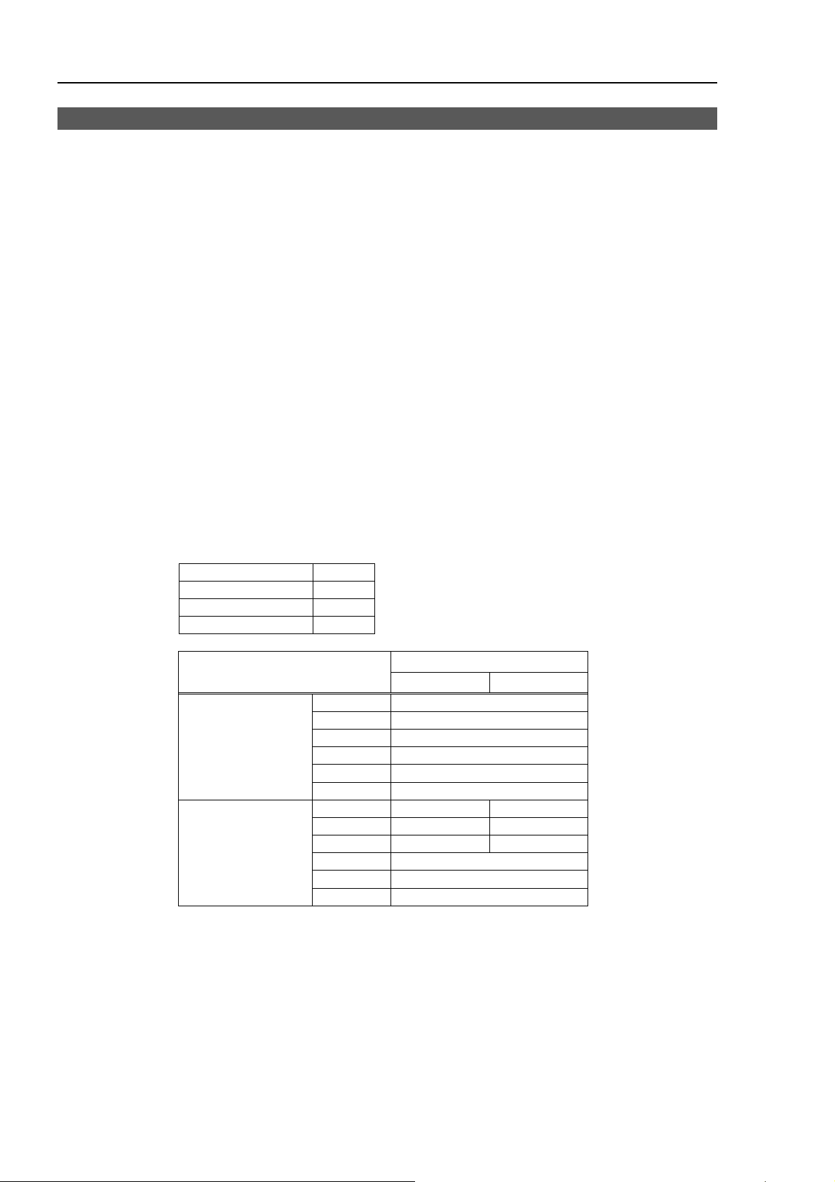
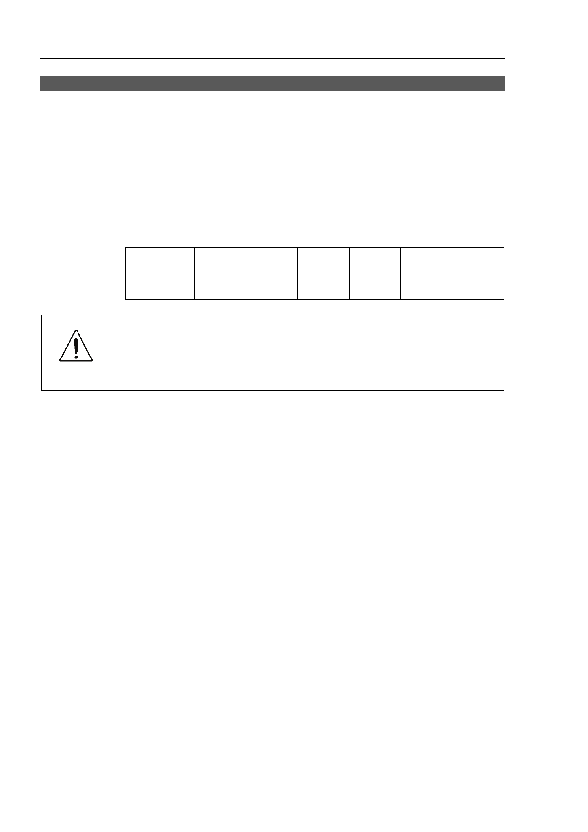
Free running distance in emergency
The operating Manipulator cannot stop immediately after the Emergency Stop switch is
pressed.
However, remember that the values vary depending on conditions such as the weight of
the end effector and work piece, WEIGHT/SPEED/ACCEL settings, operating pose, etc.
The free running time/angle/distance of the Manipulator are shown below.
Conditions of Measurement
ACCEL Setting 100
SPEED Setting 100
Load [kg] 5
WEIGHT Setting 5
Free running time
[second]
Free running angle
[degree]
Arm #1
Arm #2
Arm #3
Arm #4
Arm #5
Arm #6
Arm #1
Arm #2
Arm #3
Arm #4
Arm #5
Arm #6
RC180 / RC620
S5-A701** S5-A901**
0.4
0.4
0.4
0.4
0.4
0.1
55 60
35 40
30 35
40
50
10
6 S5 Rev.4
Page 19
Setup & Operation 1. Safety
−
−J3−
−
+
1.5 How to Move Arms the Electromagnetic Brake is Applied to
When the electromagnetic brake is applied to all arms (such as emergency mode), you
cannot move any arm by pushing it manually.
There are two methods to release the electromagnetic brake. Follow either method to
release the electromagnetic brake and move the arms manually.
1.5.1 Moving the Arm Using the Brake Release Unit
Follow the method when you just unpack the delivered boxes or when the
Controller does not start up yet.
1.5.2 Moving the Arm Using the Software
Follow the method when you can use the software.
Arm Motion
Arm #3
J4+
Joint #5
J5+
Arm #5
J6
Joint #6
Arm #6
J3+
Joint #3
Arm #2 (Lower Arm)
J2+
Arm #1
Joint #1
Bas e
J1
Joint #4
J1+
J2
Joint #2
J4
Arm #4
J5−
J6−
S5 Rev.4 7
Page 20
Setup & Operation 1. Safety
1.5.1 Moving the Arm Using the Brake Release Unit
With the electromagnetic brake is ON (such as in Emergency Stop status), you cannot
move all arms by hand.
You can move Arms by hand using the brake release unit while the controller power is
OFF or right after unpacking.
■
Before connecting/disconnecting the connector of Brake release unit, be sure to
WARNING
CAUTION
check the powers of the controller and break release unit are OFF.
Otherwise, it leads to the electrical shock or breakdown.
■
Release a brake for each joint one by one. If you need to release some brakes
at a time, take a great care. Because when some joints are released at a time,
the arms may fall to unintended directions. This is extremely dangerous and
may break the manipulator or catch your hand, fingers.
■
Take care of the arm downward motion when the brake is released.
While you are pressing the brake release switch, the arm moves downward by its
own weight. This is extremely dangerous and may break the manipulator or
catch your hand, fingers.
Width 180 mm
Depth 150 mm
Height 87 mm
Weight (Cables are not included.) 1.7 kg
Cable to the Manipulator 2 m
Power cable length 2 m
Power cable (US, Japan) 100 V specification
Power cable (EU) 200 V specification
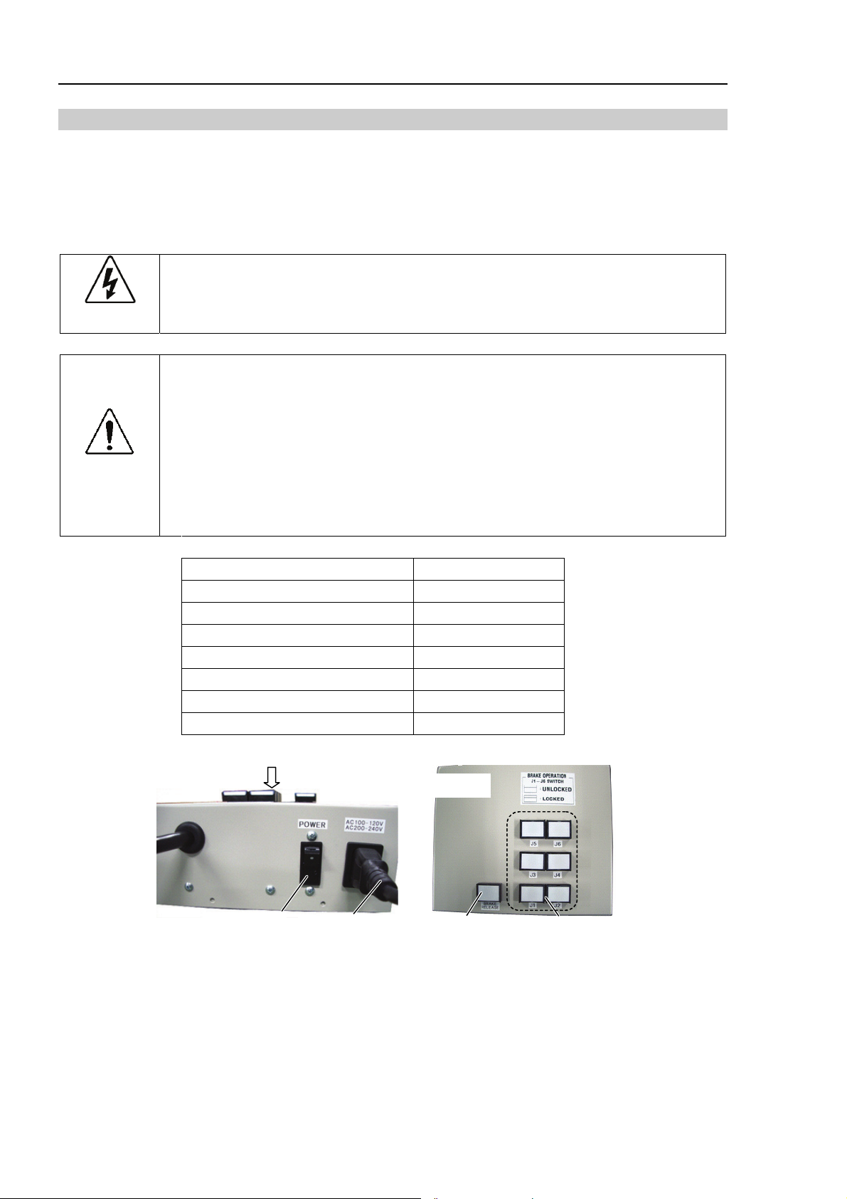
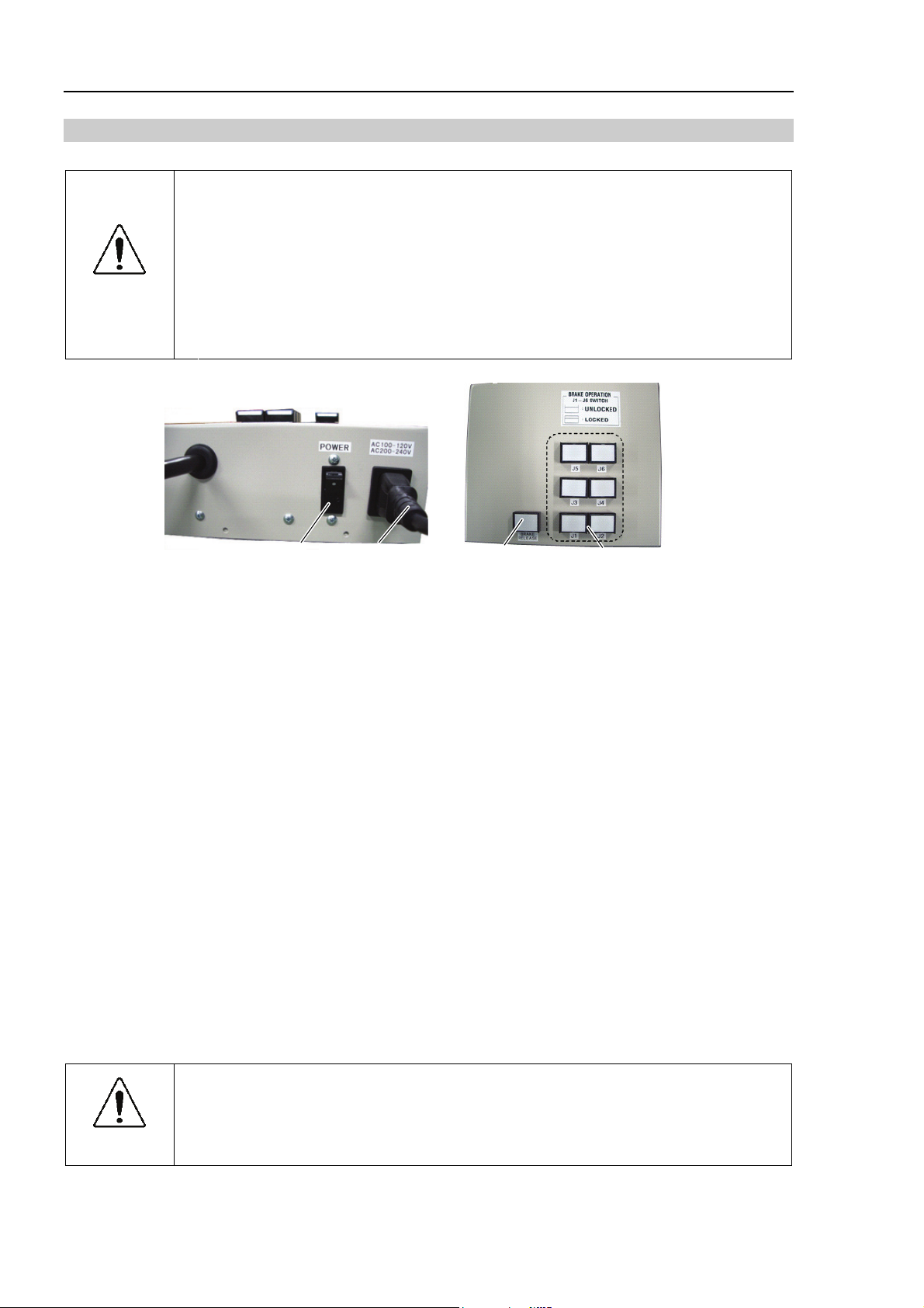
Power switch
A
Power cable
View from A
Power lamp
Arm switches
8 S5 Rev.4
Page 21

Precautions for use
■
After the brake release unit is disconnected, be sure to connect the external short
connector. Otherwise, you cannot release the brakes.
■
Keep the external short connector.
Otherwise you cannot release the brakes.
■
If you turn ON the brake release unit while the brake release switch is being
pressed, an unintended arm may move downward.
Before turning ON the brake release unit, make sure that the brake release
switch is not pressed.
■
If you turn ON the brake release unit without the connector, it may lead to the
short for the male pin used in the connector.
Before turning ON the brake release unit, make sure that the connector is
connected.
■
When you purchased several S5 series Manipulators and use the brake release
unit in the manipulator without the connection cable, you need to change the
connection cable inside the manipulator.
To skip this switching work, purchase the cable set for the brake release unit.
CAUTION
NOTE
)
Setup & Operation 1. Safety
If you purchased the manipulator and connection cable together, the cable has
been installed to the manipulator before shipment.
For additional external short connector or connection cable, please contact us.
S5 Rev.4 9
Page 22
Setup & Operation 1. Safety
(3)
How to connect the connection cable
If you purchased the manipulator and connection cable together, the cable has been
installed to the manipulator before shipment. This procedure is not necessary.
(1) Turn OFF the controller.
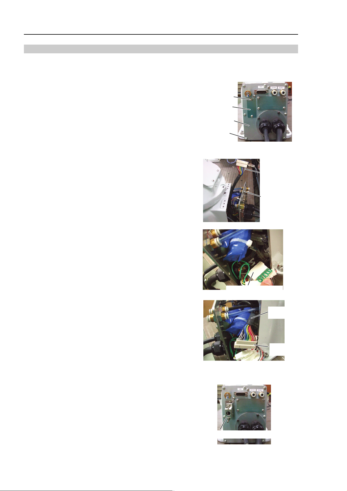
(2) Remove the hiding plate.
2-M4×10
(3) Open the connector plate.
4-M4×10
(4)
Pass the cable through the hole below
the hiding plate from the outside.
Connect the connection cable to the
connector plate.
2-M4×10
(5)
Take out the connector of internal cable
SW1.
(2) 2-M4×8
Hiding plate
Connector plate
4-M4×8
Connection cable
Connector plate
(6)
Disconnect the internal short connector.
Keep the short connector to the inside
of base or somewhere not to lose.
Internal short connector
(7)
Connect the connection cable and
internal cable SW1.
(8) Mount the connector plate. Be careful not to catch the cables.
4-M4×10
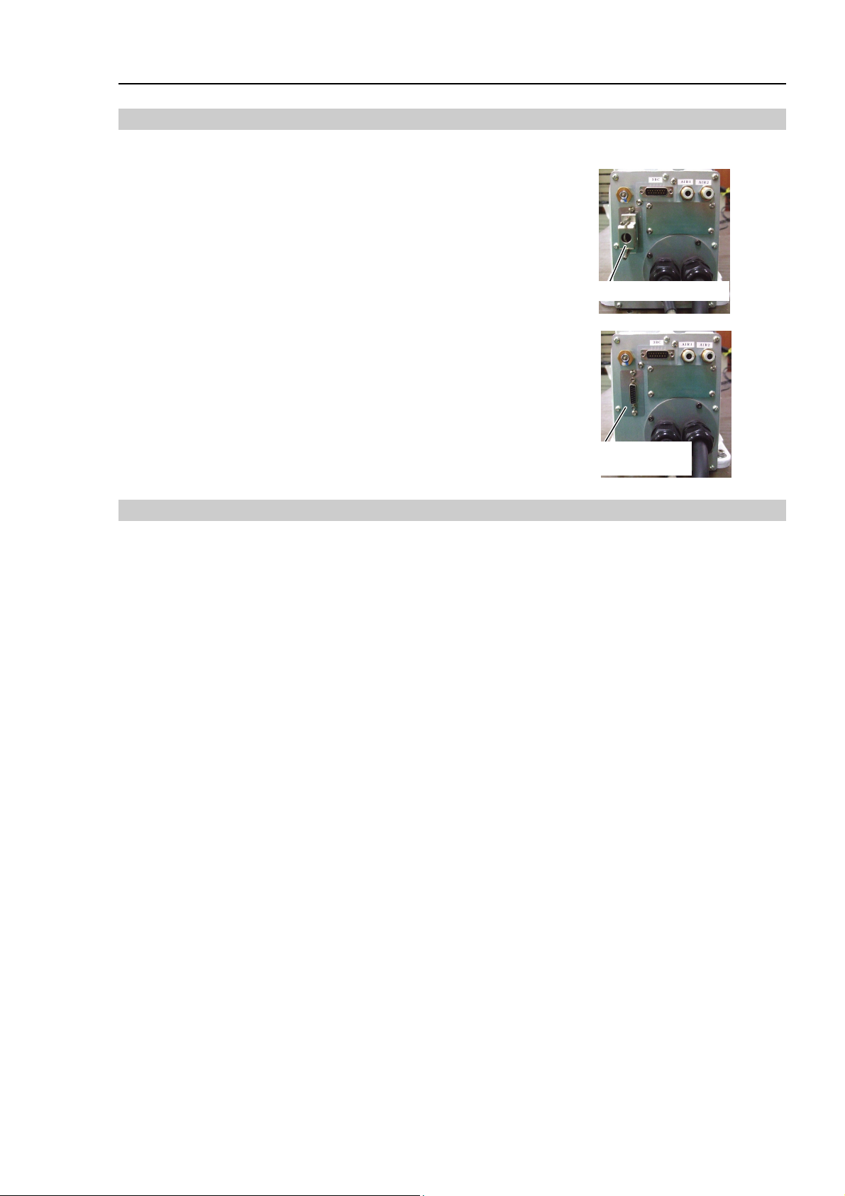
(9)
If the brake release unit is not used,
mount the external short connector.
To prevent the external short connector
from falling off, secure the two screws
included with the connector.
External short connector
Connection
cable
Connector
SW1
10 S5 Rev.4
Page 23
Mount the brake release unit
Setup & Operation 1. Safety
(1)
(2)
(3)
Turn OFF the controller.
Remove the external short connector.
Connect the brake release unit to the
connector of the connection cable.
Remove the brake release unit
(1)
Turn OFF the brake release unit.
External short connector
Connector of the
connection cable
(2)
(3)
(4)
Remove the power cable of the brake release unit.
Disconnect the brake release unit from the connector of connection cable.
Connect the external short connector to the connector of connection cable.
S5 Rev.4 11
Page 24
Setup & Operation 1. Safety
How to use the brake release unit
■
Be careful of the arm downward motion while you release the brakes.
The arm will move downward by its own weight while you are pressing a brake
release switch. This is extremely dangerous and may break the manipulator or
catch your hand, fingers.
■
CAUTION
If the arm you released the brake moves strange or slower than normal, stop the
motion promptly and contact us. The brake release unit is possibly broken and
if you keep operating the manipulator, it may lead to the brake of the
manipulator or you will be caught by the hand or fingers.
Power switch
(1)
(2)
(3)
(4)
(5)
NOTE
)
Mount the brake release unit on the manipulator.
For the mounting procedure, refer to Mount the brake release unit described in the
previous page.
Plug the power cable into the brake release unit.
Plug the power cable into the power supply plug.
Turn ON the brake release unit.
When the brake release unit is enabled, the power lamp lights up.
Press the arm switch J1 ~ J6 you want to move and then move the arm.
Press the switch again, then the brake will be released.
The brake will be enabled by pressing the switch once again.
Move the arm the brake is released by two persons or more (one presses the switch
and one moves the arm). The arm can be very heavy and needs the significant force
to move.
Power cable
Power lamp
Arm switches
When the Manipulator is a Protection-model, be aware of the followings.
■
Do not leave the brake release unit in special environmental conditions (adverse
conditions with dust and oily smoke). The brake release unit does not comply
CAUTION
12 S5 Rev.4
with IP65. Leaving the brake release unit in the special environmental
conditions may cause damage to and/or malfunction of the brake release unit.
Page 25
1.5.2 Moving the Arm Using the Software
■
Normally, release the brake of a single joint at a time. Take extra care to release
the brakes of two or more joints simultaneously from necessity. Releasing the
brakes of two or more joints simultaneously may cause hands and fingers to be
caught and/or equipment damage to or malfunction of the Manipulator as the
arms of the Manipulator may move in unexpected directions.
■
Be careful of the arm falling when releasing the brake.
CAUTION
While the brake is being released, the Manipulator’s arm falls by its own weight.
The arm falling may cause hands and fingers to be caught and/or may cause
equipment damage to or malfunction of the Manipulator.
■
Before releasing the brake, be sure to keep the Emergency Stop switch handy so
that you can immediately press the Emergency Stop switch. If you cannot
immediately press the Emergency Stop switch, you have no means to stop the
arms urgently when a wrong operation causes the arm to fall. The arm falling
may cause equipment damage to and/or malfunction of the Manipulator.
After releasing the Emergency Stop switch, Execute the following commands.
[Command Window]
>Reset
>Brake Off,[the number (from 1 to 6) corresponding to the arm whose brake will be
turned off]
Setup & Operation 1. Safety
Execute the following command to turn on the brake again.
>Brake On,[The number (from 1 to 6) corresponding to the arm whose brake will be
turned on]
S5 Rev.4 13
Page 26
Setup & Operation 1. Safety
1.6 Precaution for Operation in Low Power Status
When the power mode is low, the Manipulator will operate at low speed and low torque.
However, comparatively high torque is generated under some circumstances so that the
Manipulator can support its own weight. The maximum torque of each joint in the low
power status is shown in the following table “Max. Joint Torque in Low Power Status”.
Even though the Manipulator is in the low power status, carefully operate the Manipulator
since a comparatively high joint torque may be generated. Be careful not to get hands or
fingers caught during operations. The Manipulator may also collide with peripheral
equipment and it may cause equipment damage to or malfunction of the Manipulator.
Max. Joint Torque in Low Power Status [Unit: N·m]
Joint #1 #2 #3 #4 #5 #6
CAUTION
S5-A701**
S5-A901**
■
Carefully operate the Manipulator even though it is in the low power status. A
comparatively high joint torque may be generated. The comparatively high joint
torque may cause hands and fingers to be caught and/or may cause equipment
damage to or malfunction of the Manipulator as it may collide with peripheral
equipment.
121.80 135.82 56.59 12.72 19.21 8.01
167.06 169.78 70.74 12.72 19.21 8.01
14 S5 Rev.4
Page 27
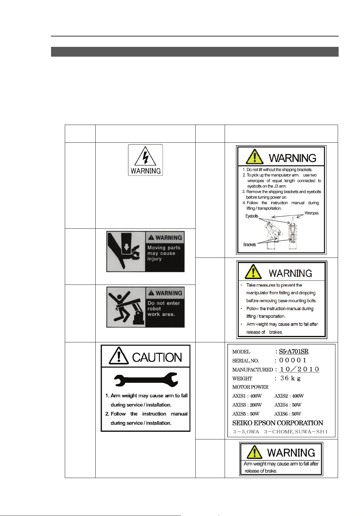
1.7 Manipulator Labels
The following labels are attached around the locations of the Manipulator where specific
dangers exist.
Be sure to comply with descriptions and warnings on the labels to operate and maintain
the Manipulator safely.
Do not tear, damage, or remove the labels. Use meticulous care when handling those
parts or units to which the following labels are attached as well as the nearby areas:
Location
of Labels
(1)
NOTE:
Hazardous voltage exists while
the Manipulator is ON. To avoid
electric shock, do not touch any
internal electric parts.
Labels
Setup & Operation 1. Safety
Location
of Labels
(5)
Labels
(2)
(3)
(6)
(7) (4)
(8)
S5 Rev.4 15
Page 28
Setup & Operation 1. Safety
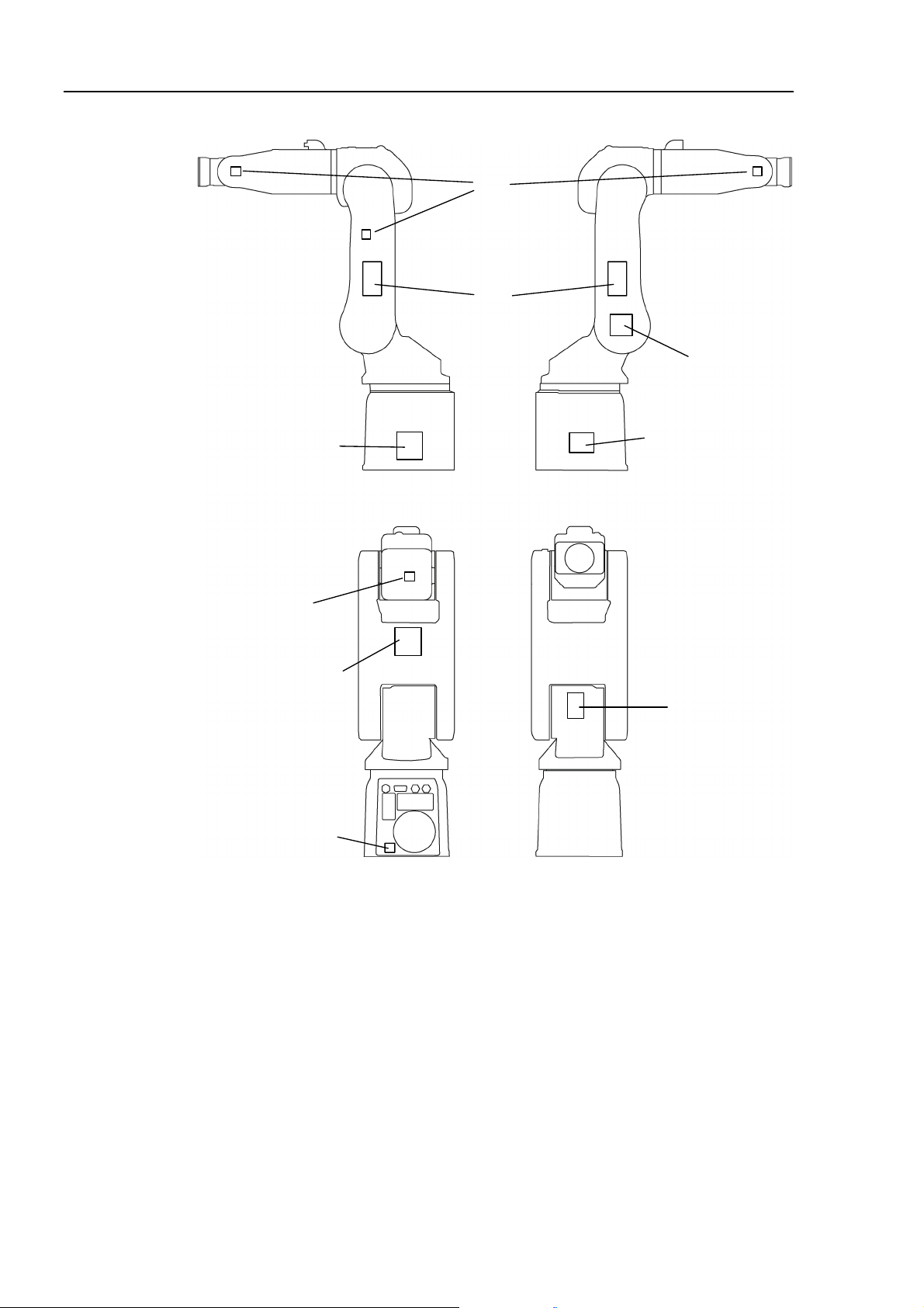
Location of Labels
(1)
(3)
(4)
(7)
Lateral View (Left side) Lateral View (Right side)
(1)
(5)
(1)
Back V ie w
Front View
(6)
(2)
16 S5 Rev.4
Page 29

2. Specifications
2.1 Features of Manipulators
(1) High-speed and high-accuracy control
S5 Manipulator is controlled at high speed and high accuracy by techniques we have
acquired while improving our SCARA robots.
- S5 Manipulator moves at high speed and stops at target points as you desire.
- High-speed and high-accuracy positioning shortens cycle time.
- Maximum operating speed has been improved at the highest level for the small
industrial robot industry.
- Residual vibration has been decreased.
- Improved rigidity of the arms reduces vibration and deflection of the Manipulator.
- S5 Manipulator holds position with great stability.
(2) High-accuracy trajectory control
The accuracy of CP trajectory control has been improved so that you can operate the
Manipulator with more flexibility while taking advantage of six degrees of freedom.
Setup & Operation 2. Specifications
(3) Available for large payloads
Large allowable moment of inertia has made it possible to support relatively large
payloads.
Optimal control for payload by using the WEIGHT and INERTIA commands make
handling large payloads more stable.
UL specification (UL1740 Conformance Type)
UL1740 is the Standard for Industrial Robots and Robotic Equipment established by
Underwriters Laboratories Inc. (UL). The UL1740 conformance product has a safety
mark which shows that Underwriters Laboratories Inc. (UL) has recognized it.
In the United States, the robot system is recommended to be used with the Manipulators
and Controller that conform to UL1740 in accordance with ANSI/RIA R15.06.
S5 Rev.4 17
Page 30
Setup & Operation 2. Specifications
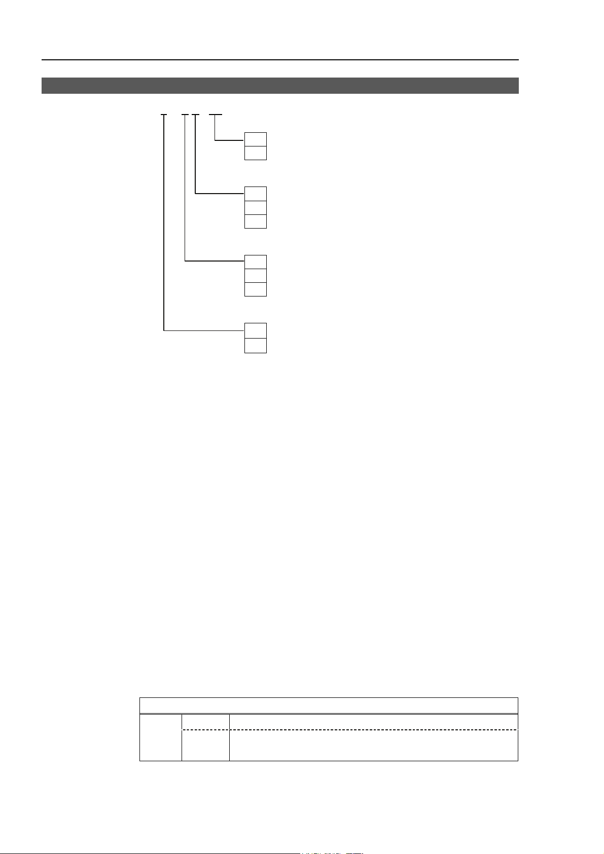
2.2 Model Number
S5 - A 701 S R - UL
Environment
UL specification
UL : UL compliant
□
: Non UL compliant
Type
□
: Table Top mounting
W : Wall mounting
R : Ceiling mounting
Environment
S : Standard model
C : Clean-room model
P : Protection-model
Arm length
7 : 706 mm
9 : 895 mm
Cleanroom-model
Cleanroom-model Manipulator includes additional features that reduce dust emitted by
the Manipulator to enable use in clean room environments.
Cleanliness level : Class ISO 3 (ISO14644-1)
In previous criteria;
Clean Class: 10 or its equivalent. Amount of Dust (0.1 µm
3
diameter or larger) in 28317 cm
(1cft) sample-air around the
center of the motion rang: 10 particles or less.)
Exhaust System : Exhaust port diameter:
Inner diameter: ø12 mm / Outer diameter: ø16 mm
Exhaust tube : Polyurethane tube
Outer diameter: ø12 mm (Inner diameter:ø8 mm)
or Inner diameter ø16mm.
3
Recommended exhaust flow rate : Approx. 1000 cm
/s (Normal)
Protection-model (IP65)
The Protection-model Manipulators operate under adverse conditions with dust and oily
smoke.
IP (International Protection) for the Protection-model Manipulator indicates
International Standard of the protection level against dust and water.(IEC 60529, JIS
C0920)
Degree of protection
Dust : 6 No ingress of dust.
IP65
Water : 5
Water projected by a nozzle against enclosure from any direction
shall have no harmful effects.
For details on the specifications, refer to Setup & Operation: 2.4 Specifications.
18 S5 Rev.4
Page 31

+J1−
−
+
−
A
E
A
EFA
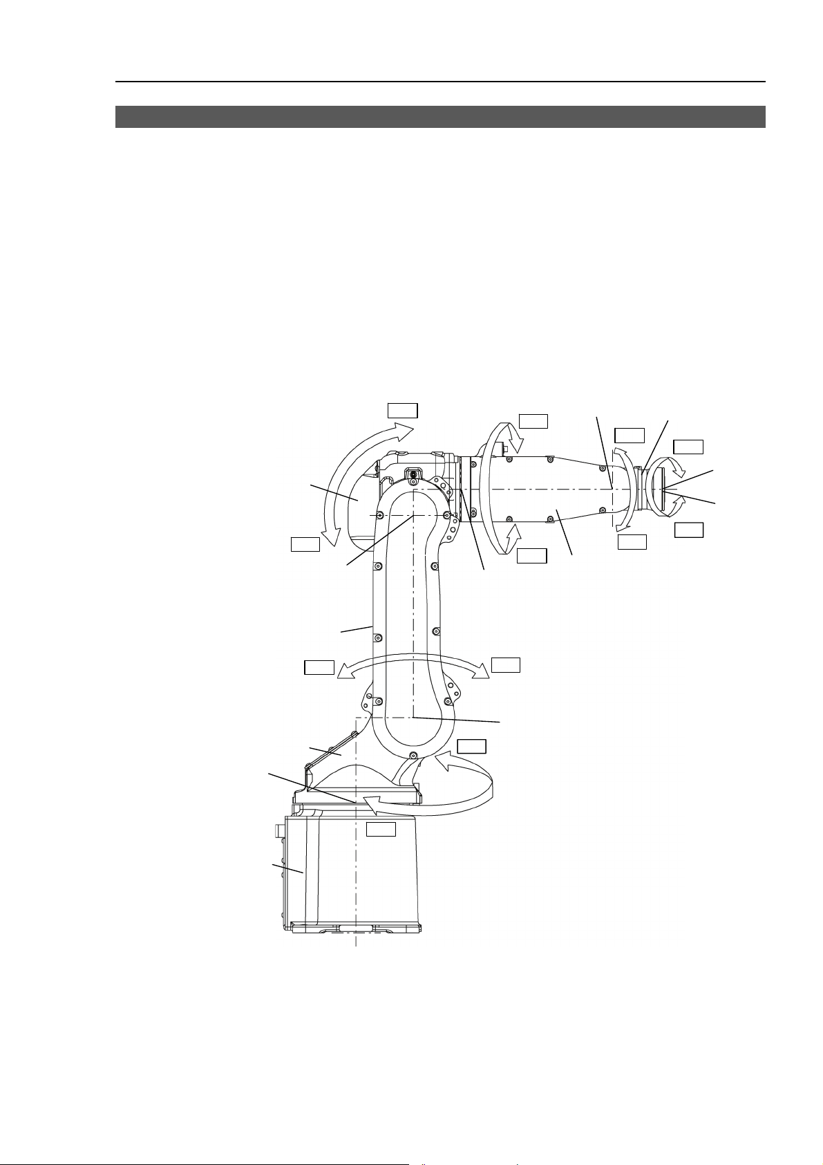
2.3 Appearance
Part Names and Motion Range of Each Arm
LED Lamp
(This lamp lights up
while the motors are ON.)
Arm #3
Setup & Operation 2. Specifications
Upper Arm (Arms #3 to #6)
J3−
J4
Joint #5
J5+
Arm #5
J6+
Joint #6
Arm #6
Arm #2 (Lower Arm)
Arm #1
Joint #1
J3+
Joint #3
J2+
J4
Joint #4
J2
Joint #2
J1
Base
Arm #4
Arm #1 : The whole Manipulator revolves.
Arm #2 : The lower arm swings.
Arm #3 : The upper arm swings.
Arm #4 : The wrist revolves.
Arm #5 : The wrist swings.
Arm #6 : The wrist rotates.
J5−
J6−
Arm Motion
Details of Connector Plate (View A)
A : Grease Supply Opening
B : User Cable Connector
(15 p in D-sub connector)
B C D
F
Standard model
Protection-model
B C D
G
Cleanroom-model
C : Air Supply Opening
D : Air Supply Opening
E : Signal Connector
F : Power Connector
G : Exhaust Port
(Only Cleanroom-mode)
S5 Rev.4 19
Page 32

Setup & Operation 2. Specifications
(
)
9
5
A
Outer Dimensions
S5-A701** [Unit: mm]
ir Supply Opening
M5 Tap
with cover plug
70
423
298
55
Space
for cables
87
90 or more
4-M8 Tap P1.25 Depth: 16mm
40
752
59
2×2 M4 Tap P0.7Depth 8 mm
Front & Back
100 305
88 1 109
80
2
40
114
11 0
2-M4 Tap P0.7 Depth: 8mm
09
66
330 310
19
623.2
473
150.2
20 S5 Rev.4
Page 33

Setup & Operation 2. Specifications
(
S5-A901** [Unit: mm]
Air Supply Opening
M5 Tap
with c over plug
70
55
523
398
Space
for cables
87
90 or more
4-M8 Tap P1.25 Depth: 16mm
40
842
2×2 M4 Tap P0.7Depth 8 mm
Fron t & Back)
100 405
88
25
40
114
11 0
2-M4 Tap P0.7 Depth: 8mm
80
66
109 109
330 400
199
150.2
723.2
573
S5 Rev.4 21
Page 34

Setup & Operation 2. Specifications
−
+
−
Standard Motion Range
S5-A701** [Unit: mm] (° = degree)
Top View
Lateral View
+170° (Arm #1)
R235
R706
−170° (Arm #1)
Joint #2
501
0 pulse po sition
706
Motion range of P point*
P point*
Joint #1
0 pulse position
Front View
305 8088
15
135°
40 310 330
+65°
225°
948
752
156 179
246
51 233
114 277
203
246
136°
135°
150°
* P point: Intersection of the rotation
centers for Joints #4, #5, and #6
P point*
Joints #3, #5
0 pulse position
239
Motion range of P point*
Joints # 4, #6
0 pulse position
−190°
−360° +360°
+190°
22 S5 Rev.4
Page 35

Setup & Operation 2. Specifications
+
+
−
+
+
S5-A901** [Unit: mm] (° = degree)
Top View
+170 ° (Arm #1)
R267
R895
Motion range of P point*
P point*
Joint #1
0 pulse position
113 7
Lateral View
40 400 330
97
255°
−170° (Arm #1 )
681
65°
Joint #2
0 pulse position
9
405
895
−150°
Front View
8088
135°
P point*
135°
Joints #3 , #5
0 pulse position
198
Joints # 4, #6
0 pulse position
−190°
−360°
190°
360°
317 842
423
341
400
14
132
209
251
138°
Motion range of P point*
* P point: Int erse ction of t he r otation
centers for Joints #4, #5, and #6
S5 Rev.4 23
Page 36

Setup & Operation 2. Specifications
2.4 Specifications
2.4.1 Specifications Table
Item Specification
Model Number
S5-A701S S5-A701C S5-A701P S5-A901S S5-A901C S5-9701P
Degree of protection - - IP65 - - IP65
Cleanliness level (ISO class) - Class 3 - - Class 3 -
Weig ht (not including cables, shipping jigs)
Driving method All arms
Arm #1
Arm #2
Max. operating
*1
speed
Arm #3
Arm #4
Arm #5
Arm #6
Repeatability Arm #1 to #6
Arm #1
Arm #2
Max. motion range
Arm #3
Arm #4
Arm #5
Arm #6
Arm #1
Arm #2
Max. pulse range
Arm #3
Arm #4
Arm #5
Arm #6
Arm #1
Arm #2
Resolution
Arm #3
Arm #4
Arm #5
Arm #6
Arm #1
Arm #2
Motor power
consumption
Arm #3
Arm #4
Arm #5
Arm #6
Payload *2
Rated
Max.
Arm #4
Allowable moment
Arm #5
Arm #6
Allowable moment
of inertia (GD
2
/4) *3
Arm #4
Arm #5
Arm #6
(Wall mounting: ±1044777 pulse)
(with conditions) 5 (7) kg
36 kg : 80 lb. 38 kg : 84 lb.
AC servo motor
6.56 rad/s, 376 deg/s 4.71 rad/s, 270 deg/s
6.11 rad/s, 350 deg/s 4.88 rad/s, 280 deg/s
6.98 rad/s, 400 deg/s 5.23 rad/s, 300 deg/s
7.85 rad/s, 450 deg/s
7.85 rad/s, 450 deg/s
12.57 rad/s, 720 deg/s
±0.02 mm ±0.03 mm
±170 deg (Wall mounting: ±30 deg)
−150 deg, +65 deg
−70 deg, +190 deg −72 deg, +190 deg
±190 deg
±135 deg
±360 deg
±5920402 pulse
(Wall mounting: ±1433054 pulse)
+2524350 pulse
−5825423 pulse
+6149057 pulse
−2265442 pulse
±8120639 pulse
+3155438 pulse
−7281778 pulse
+7686321 pulse
−2912712 pulse
±5534152 pulse
±3932160 pulse
±6553600 pulse
0.00002871 deg/pulse 0.00002093deg/pulse
0.00002574 deg/pulse
0.00003089 deg/pulse
0.00002059 deg/pulse
0.00002471 deg/pulse
0.00003433 deg/pulse
0.00003433 deg/pulse
0.00005493 deg/pulse
400 W
400 W
200 W
50 W
50 W
50 W
2 kg
12 N·m (1.22kgf·m)
12 N·m (1.22kgf·m)
7 N·m (0.71kgf·m)
2
0.3 kg·m
0.3 kg·m
0.1 kg·m
2
2
24 S5 Rev.4
Page 37

Setup & Operation 2. Specifications
Item Specification
Installed wire for customer use 15 wires : D-sub 15 pin connector
2 pneumatic tubes (ø6 mm),
Installed pneumatic tube for customer use
Environmental
requirements
*4
Ambient Temperature
Ambient relative
humidity
Equivalent continuous A-weighted sound
pressure level
*5
Allowable pressure: 0.49MPa
(5kgf/cm
2
) (71 psi)
0 deg.C to 45 deg.C
(with minimum temperature variation)
20% to 80% (no condensation)
= 80 dB (A) or under
L
Aeq
Applicable Controller RC180, RC620
SPEED 5 (100)
ACCEL 5, 5 (100, 100)
Default values
(Max. setting values)
SPEEDS 50 (2000)
ACCELS 200 (25000)
FINE
10000, 10000, 10000, 10000, 10000, 10000
(65535, 65535, 65535, 65535, 65535, 65535)
WEIGHT 2, 0
ANSI/RIA R15.06 compliance
Safety standard
CE compliance
EN775, EN60204-1, EN55011,
EN61000-6-2, EN60950
*1 In the case of PTP control
*2 When the setting payload is more than 5 kg and less than or equal to 7 kg, refer to the section “Restrictions
on payload exceeding 5 kg (more than 5 kg and less than or equal to 7 kg)” in the Setup & Operation 4.3.1
WEIGHT Setting.
*3 In the case where the center of gravity is at the center of each arm. If the center of gravity is not at the
center of each arm, set the eccentric quantity using INERTIA command.
*4 For details of the environmental requirements, refer to the Setup & Operation 3.1 Environmental
Conditions.
*5 Conditions of Manipulator at measurement are as follows:
Operating conditions: Under rated load, 6 arms simultaneous motion, maximum speed,
maximum acceleration, and duty 50%.
Measurement point: 1000 mm apart from the rear of Manipulator
2.4.2 Option Table
Brake release unit
Camera plate
PS compatible plate
PS installation compatible plate
Mechanical stops for Arm #1, #2, #3 *
* If manipulator is equipped with the mechanical stop, it conforms to the safety standard “ANSI/RIA
R15.06”and “CE”, but not to “UL1740”.
S5 series has the following options:
Item Specification
Refer to Setup & Operation
1.5.1 Moving the Arm Using the Brake Release Unit.
Call your EPSON Regional Sales Manager for the detail
information.
S5 Rev.4 25
Page 38

Setup & Operation 2. Specifications
2.5 How to Set the Model
The Manipulator model for your system has been set before the shipment from the factory.
It is normally not required to change the model when you receive your system.
■
When you need to change the setting of the Manipulator model, be sure to set the
Manipulator model properly. Improper setting of the Manipulator model may
CAUTION
result in abnormal or no operation of the Manipulator and/or cause safety
problems.
NOTE
)
If an MT label is attached to the rear of a Manipulator, the Manipulator has custom
specifications. If the Manipulator has custom specifications, the methods for setting the
model may differ from those described below. Please contact us with the number on the
MT label.
The method for setting the Manipulator model depends on the software used.
Refer to the chapter Robot Configuration in the EPSON RC+ User’s Guide.
26 S5 Rev.4
Page 39

Setup & Operation 3. Environment and Installation
3. Environment and Installation
Installation and transportation of robots and robotic equipment shall be performed
by qualified personnel and should conform to all national and local codes.
3.1 Environmental Conditions
A suitable environment is necessary for the robot system to function properly and safely.
Be sure to install the robot system in an environment that meets the following conditions:
Item Conditions
Ambient temperature*1 0 deg C to 45 deg C (with minimum temperature variation)
Ambient relative humidity 20% to 80% (no condensation)
First transient burst noise 2 kV or less (Power wire)
1 kV or less (Signal wire)
Electrostatic noise 4 kV or less
Environment · Install indoors.
· Keep away from direct sunlight.
· Keep away from dust, oily smoke, salinity, metal
powder or other contaminants.
· Keep away from flammable or corrosive solvents
and gases.
· Keep away from water.
· Keep away from shock or vibration.
· Keep away from sources of electric noise.
*1 The ambient temperature conditions are for the Manipulators only. For the Controller
the Manipulators are connected to, refer to the Controller manual.
NOTE
)
Manipulators are not suitable for operation in harsh environments such as painting areas,
etc. When using Manipulators in inadequate environments that do not meet the above
conditions, please contact us.
S5 Rev.4 27
Page 40

Setup & Operation 3. Environment and Installation
For the Protection-model Manipulator, be sure to install the robot system in an
environment that also meets the following conditions:
Item Conditions
Environment · Install indoors.
· Keep away from direct sunlight.
· Keep away from salinity or other contaminants.
· Keep away from flammable or corrosive solvents (including
water)*² and gases.
· Keep away from shock or vibration.
· Keep away from sources of electric noise.
· It can be used under conditions with dust, oily smoke, metal
powder or other contaminants.*³
*2 The Manipulator body is mainly made of iron and aluminum. It is not rust-proofed.
Do not use the Manipulator under conditions where the Manipulator can expose to
water or any other corrosive liquid.
*3 Any contaminants that can deteriorate sealing performance of nitrile rubber oil sealing,
O-rings, packing seals and liquid gasket should be avoided.
WARNING
Special Environmental Conditions
The protective seals are attached on the Protection-model Manipulator to prevent dust,
water, etc. from the outside. Follow the precautions in use environment described below:
The surface of the Manipulator has general oil resistance. However, if your requirements
specify that the Manipulator must withstand certain kinds of oil, please consult your
distributor.
Rapid change in temperature and humidity can cause condensation inside the Manipulator.
If your requirements specify that the Manipulator handles food, please consult your
distributor to check whether the Manipulator gives damage to the food or not.
The Manipulator cannot be used in corrosive environments where acid or alkaline is used.
In a salty environment where the rust is likely to gather, the Manipulator is susceptible to
rust.
The controller used with the Protection-model Manipulator does not have protection
features for dusty, wet, or oily environment. The controller must be placed in an
environment that meets the specified conditions.
■
Use an earth leakage breaker on the AC power cable of the Controller to avoid
the electric shock and circuit breakdown caused by an unexpected water leak.
Prepare the earth leakage brake that pertains the controller you are using. For
details, refer to the controller manual.
28 S5 Rev.4
Page 41

Setup & Operation 3. Environment and Installation
3.2 Unpacking, Transportation, and Relocation
Using a cart or similar equipment, transport the Manipulator in the same conditions as it
was delivered. Observe the following when unpacking the Manipulator.
THE INSTALLATION SHALL BE MADE BY QUALIFIED INSTALLATION
PERSONNEL AND SHOULD CONFORM TO ALL NATIONAL AND LOCAL
CODES.
■
Only authorized personnel should perform sling work and operate a crane or
forklift. When these operations are performed by unauthorized personnel, it is
extremely hazardous and may result in serious bodily injury and/or severe
WARNING
equipment damage to the robot system.
■
Stabilize the Manipulator with your hands when hoisting it. Unstable hoisting is
extremely hazardous and may results in serious bodily injury and/or severe
equipment damage to the robot system as the fall of the Manipulator.
■
When removing the anchor bolts, support the Manipulator to prevent falling.
Removing the anchor bolts without supporting the Manipulator may get hands,
fingers, or feet caught as the Manipulator will fall.
CAUTION
■
Do not remove the wire tie securing the arm until you finish the installation.
You may get your hands caught in the Manipulator when the wire tie is removed
before completing the installation.
■
To carry the Manipulator, have at least 3 people to work on it and secure the
Manipulator to the delivery equipment or hold it by hand. Do not hold the bottom
of the base (the screened parts in the figure). Holding these parts by hand is
extremely hazardous and may cause your hands and fingers to be caught or cut
by the grounding electrode.
S5-A701**
Approx. 38 kg (Manipulator weight: 36 kg (80 lb.))
S5-A901**
Approx. 40 kg (Manipulator weight: 38 kg (84 lb.))
Shipping bolts
and jigs
DO NOT hold
the bottom of the
base by hand.
■
Avoid excessive vibration or shock during Manipulator transporting. Excessive
vibration or shock may cause equipment damage to and/or malfunction of the
Manipulator.
S5 Rev.4 29
Page 42

Setup & Operation 3. Environment and Installation
Use a crane for transporting the Manipulator during unpacking and relocation.
When using a lifting device other than a crane or forklift for transportation, avoid
applying external force to the arms and motors of the Manipulator.
Check that the eyebolts are securely fastened.
The weight of the Manipulator S5-A701** (S5-A901**) is approx. 38 (40) kg
including the shipping bolts and jigs (the Manipulator weight: 36 (38) kg (80 (84)
lb.)). Use a cable strong enough to withstand the weight.
The attached eyebolts are designed to support the Manipulator weight. Do not
use them for anything other than transporting the Manipulator.
Mount the shipping bolts and jigs for transporting the Manipulator.
After transporting the Manipulator, remove the eyebolts and keep them for future
use.
When transporting the Manipulator for a long distance, secure it to the delivery
equipment so that the Manipulator cannot fall. If necessary, pack the Manipulator
in the same way as it was delivered.
When condensation occurs on the Manipulator during transport or storage, turn ON
the power only after the condensation dries.
When using the Manipulator for the robot system again after long-term storage,
perform a test run to verify that the Manipulator works properly. Then, operate the
Manipulator thoroughly.
3.2.1 Using a Crane
To hoist the Manipulator with a crane, secure the Manipulator with shipping bolts and jigs
and posture the Manipulator as shown in the figures below (the same posture as shipping).
Using a cable threaded through the eyebolts attached to the Manipulator as shown.
Transporting Posture
° = degree
( ) is for S5-A901**.
29°
(22°)
59°
(52°)
60°
(60°)
30 S5 Rev.4
Page 43

3.2.2 Using a Forklift
Position the Manipulator as shown in the figures below (the same posture as shipping) and
secure it onto a pallet with shipping bolts and jigs. Insert the forklift claws under the
pallet and transport the Manipulator together with the pallet. The pallet must have
enough strength to bear the weight of the Manipulator. Transporting of the Manipulator
must be performed slowly in order to avoid overturning or slippage.
Transporting Posture
Setup & Operation 3. Environment and Installation
Bolt
(4-M10)
Pallet
Inset here the forklift claws.
3.2.3 Removing / Attaching the Shipping Bolts and Jigs
The shipping bolts and jigs are attached to the Manipulator as shown the figure below
(points A, B) for protecting the Manipulator from various external forces during
transportation. The jigs are painted yellow.
Point A : 6-M5×14 hexagon socket head cap bolts with plain washers
and disc spring washers
Point B : 2-M6×10 hexagon socket head cap bolts with plain washers
and disc spring washers
Point A
Controller
Point B
S5 Rev.4 31
Page 44

Setup & Operation 3. Environment and Installation
Removal
(1) Remove the bolts combining the shipping jigs at the point A.
6-M5×14 hexagon socket head cap bolts with plain washers and disc spring washers
NOTE
)
Installation
3.2.4 Relocating
(2) Remove the bolts securing the shipping jigs at the point B. Then, remove the upper
part of the shipping jigs.
2-M6×10 hexagon socket head cap bolts with plain washers and disc spring washers
Before turning on the power, be sure that the shipping bolts and jigs have been removed.
The shipping bolts and jigs must then be stored for future use, in the event that the
Manipulator must be moved again.
(1)
Position the Manipulator as show in the figure above.
(2) Attach the upper part of the shipping jigs to the Manipulator at the point B. Secure
it with the bolts.
2-M6×10 hexagon socket head cap bolts with plain washers and disc spring washers
(3) Secure the shipping jigs at the point A with the bolts.
6-M5×14 hexagon socket head cap bolts with plain washers and disc spring washers
Follow the procedures described below when relocating the Manipulator.
(1) Turn OFF the power for all devices and unplug the cables.
Remove the mechanical stops if using them to limit the motion range.
NOTE
)
For details on the motion range, refer to the Setup & Operation 5.2 Motion Range
Setting of Arm #1 by Mechanical Stops.
(2)
Unscrew the anchor bolts.
Then, remove the Manipulator from the base table.
(3)
Position the Manipulator as shown in the figure. Then, secure the Manipulator to
the delivery equipment or have three or more people to carry the Manipulator.
Do not hold the bottom of the base (the screened parts in the figure). Holding these
parts by hand is extremely hazardous and may cause your hands and fingers to be
caught or cut by the grounding electrode.
S5-A701**
Approx. 38 kg (Manipulator weight: 36 kg (80 lb.))
S5-A901**
Approx. 40 kg (Manipulator weight: 38 kg (84 lb.))
Shipping bolts
and jigs
DO NOT hold
the bottom of the
base by hand.
32 S5 Rev.4
Page 45

3.3 Mounting Dimensions
Mounting Area
Be sure to have the following space available in addition to the space for mounting the
Manipulator, Controller, and peripheral equipment.
Space for teaching points
Space for maintenance and inspections
Space for cables
NOTE
)
The minimum bend radius of the power cable is 90 mm. When installing the cable, be
sure to maintain sufficient distance from obstacles. In addition, leave enough space for
other cables so that they are not bent forcibly.
Mounting Dimensions [Unit: mm]
Setup & Operation 3. Environment and Installation
90
Power Cable
A
194
138
160
194
105
9
12
View A
160
100±0.05
4-ø12(Mounting hole)
100±0.05
S5 Rev.4 33
Page 46

Setup & Operation 3. Environment and Installation
3.4 Installation
THE INSTALLATION SHALL BE MADE BY QUALIFIED INSTALLATION
PERSONNEL AND SHOULD CONFORM TO ALL NATIONAL AND LOCAL
CODES.
■
To ensure safety, a safeguard must be installed for the robot system. For details
on the safeguard, refer to the Installation and Design Precautions in the Safety
chapter of the EPSON RC+ User’s Guide or the Safety 1.3 Design Precautions in
the SPEL CT User’s Guide.
■
Install the Manipulator at a location with sufficient space so that a tool or a work
piece on the end effector does not reach a wall or a safeguard when the
Manipulator extends its arm fully while holding a work piece. Installing the
Manipulator at a location with insufficient space is extremely hazardous and may
result in serious bodily injury and/or severe equipment damage to the robot
system as a tool or a work piece may collide with a wall and a safeguard.
■
Anchor the Manipulator before turning ON the power to or operating the
WARNING
Manipulator. Turning ON the power to or operating the Manipulator that is not
anchored is extremely hazardous and may result in serious bodily injury and/or
severe equipment damage to the robot system as the Manipulator may fall down.
CAUTION
■
Before installing and operating the Manipulator, make sure that all parts of the
Manipulator are in place and have no external defects. Missing or defective
parts may cause improper operation of the Manipulator. Improper operation of
the Manipulator is extremely hazardous and may result in serious bodily injury
and/or severe equipment damage to the robot system.
■
Before first turning ON the power, be sure to remove the shipping bolts and jigs
from the Manipulator. Turning ON the power while the shipping bolts and jigs
are attached may result in equipment damage to the Manipulator.
■
Do not remove the wire tie securing the arm until you finish the installation.
You may get your hands caught in the Manipulator when the wire tie is removed
before completing the installation.
■
The robot system must be installed to avoid interference with buildings,
structures, utilities, other machines and equipment that may create a trapping
hazard or pinch points.
The following sections describe the installation of the Standard Manipulator.
3.4.1 Table Top Mounting
3.4.2 Floor Mounting
For Cleanroom-model / Protection-model Manipulator, refer to each section.
3.4.3 Cleanroom-model
3.4.4 Protection-model
34 S5 Rev.4
Page 47

3.4.1 Base Table Mounting
A base table for anchoring the Manipulator is not supplied. Please make or obtain the
base table for your Manipulator. The shape and size of the base table will differ
depending on the use of the robot system. For your reference, we list some basic
Manipulator table requirements here.
The base table must not only be able to bear the weight of the Manipulator but also be able
to withstand the dynamic movement of the Manipulator when it operates at maximum
acceleration. Ensure that there is enough strength on the base table by attaching
reinforcing materials such as crossbeams.
The torque and reaction force produced by the movement of the Manipulator are as
follows:
S5-A701** S5-A901**
Setup & Operation 3. Environment and Installation
Max. Horizontal rotating torque
Max. Horizontal reaction force
Max. Vertical rotating torque
Max. Vertical reaction force
There are 4 threaded holes for the Manipulator base. Use M10 mounting bolts
conforming to the strength, ISO898-1 property class: 12.9. For the dimensions, refer to
the Setup & Operation 3.3 Mounting Dimensions.
The plate for the Manipulator mounting face should be 30 mm thick or more and made of
steel to reduce vibration. The surface roughness of the steel plate should be 25 μm or
less.
The base table must be secured on the floor to prevent it from moving.
The Manipulator must be installed horizontally.
When using a leveler to adjust the height of the base table, use a screw with M16 diameter
or more.
If you are making holes for the cables and passing the cables through the holes on the base
table, see photos below.
600 N·m 900 N·m
1000 N 1400 N
800 N·m 900 N·m
3000 N 3500 N
[Unit: mm]
47
95
Power C able
Connector
M/C Cable
NOTE
)
S5 Rev.4 35
Do not remove the M/C cables from the Manipulator.
For environmental conditions regarding space when placing the Controller on the base
table, refer to the Controller manual.
26
53
18
Signal Cable
Connector
Page 48

Setup & Operation 3. Environment and Installation
Manipulator Base
Bolt (4-M10)
Spring W asher
Manipulator Base
10
Base Table
30 mm or mo re
Anchor Bolt (M10 or la rger)
Bas e Table
3.4.2 Floor Mounting
The floor should have enough strength to bear the weight of the Manipulator. Construct a
solid foundation with the appropriate thickness to withstand maximum torque and reaction
force of the Manipulator (refer to the table in Setup & Operation 3.4.1 Base Table
Mounting). As a rough standard, when there is a concrete floor with thickness of 150
mm or more, the base of the Manipulator can be secured directly to the floor with M10
anchor bolts. However, before mounting the Manipulator, check that the floor is level
and that all cracks, etc. are repaired. Any thickness less than 150 mm is insufficient for
mounting, even if the floor is concrete.
Anchor bolt (4-M10)
150 mm
or more
Concrete
36 S5 Rev.4
Page 49

3.4.3 Cleanroom-model
For Cleanroom-model Manipulator, the following procedure is necessary before
installation.
(1) Unpack it outside of the clean room.
(2) Secure the Manipulator to delivery equipment such as a pallet with bolts so that the
Manipulator does not fall.
(3) Wipe off the dust on the Manipulator with a little alcohol or distilled water on a
lint-free cloth.
(4) Carry the Manipulator in the clean room.
(5) Refer to the installation procedure of each Manipulator model and install the
Manipulator.
(6) Connect an exhaust tube (ø 8 mm) to the exhaust port.
3.4.4 Protection-model
Setup & Operation 3. Environment and Installation
WARNING
CAUTION
Refer to the installation procedure of each Manipulator model and install the Manipulator.
When the Manipulator is a Protection-model, be aware of the followings.
■
Connect the power cable connection and the signal cable connector to the
Manipulator immediately after the Manipulator installation. The Manipulator
without connecting them may result in electric shock and/or malfunction of the
robot system as it cannot ensure IP65.
■
When operating the Manipulator under special environmental conditions (adverse
conditions with dust and oily smoke), do not place the controller in the same
condition since the controller does not comply with IP65. Doing so may cause
equipment damage to and/or malfunction of the controller.
S5 Rev.4 37
Page 50

Setup & Operation 3. Environment and Installation
3.5 Connecting the Cables
■
Before performing any replacement procedure, turn OFF the Controller and
related equipment, and then pull out the power plug from the power source.
Performing any replacement procedure with the power ON is extremely
hazardous and may result in electric shock and/or malfunction of the robot
system.
■
Be sure to connect the AC power cable to a power receptacle. DO NOT connect
it directly to a factory power source. To shut off power to the robot system, pull
out the power plug from the power source. Performing any work while
connecting the AC power cable to a factory power source is extremely hazardous
and may result in electric shock and/or malfunction of the robot system.
■
WARNING
Be sure to connect the cables properly. Do not allow unnecessary strain on the
cables. (Do not put heavy objects on the cables. Do not bend or pull the
cables forcibly.) The unnecessary strain on the cables may result in damage to
the cables, disconnection, and/or contact failure. Damaged cables,
disconnection, or contact failure is extremely hazardous and may result in electric
shock and/or improper function of the robot system.
CAUTION
■
Before wiring, turn OFF the Controller and related equipment, and then pull up a
warning sign (e.g. DO NOT TURN ON THE POWER.). Wiring with the power
ON is extremely hazardous and may result in electric shock and/or malfunction of
the robot system.
■
When connecting the Manipulator and the Controller, make sure that the serial
numbers on each equipment match. Improper connection between the
Manipulator and Controller may not only cause improper function of the robot
system but also safety problems. The connection method varies with the
Controller used. For details on the connection, refer to the Controller manual.
■
Only authorized or certified personnel should be allowed to perform wiring.
Wiring by unauthorized or uncertified personnel may result in bodily injury and/or
malfunction of the robot system.
38 S5 Rev.4
Page 51

3.5.1 Cable Connections
Cable Connections
Connect the power connector and signal connector of the M/C cables to the Controller.
<Example> Connection of S5 series Manipulator and Robot Controller RC180
Setup & Operation 3. Environment and Installation
M/C po wer cable
WARNING
CAUTION
M/C signal cable
Cleanroom-model
When the Manipulator is Cleanroom-model, be aware that it needs an exhaust system.
Protection-model
When the Manipulator is a Protection-model, be aware of the followings.
■
Connect the power cable connection and the signal cable connector to the
Manipulator immediately after the Manipulator installation. The Manipulator
without connecting them may result in electric shock and/or malfunction of the
robot system as it cannot ensure IP65.
■
When operating the Manipulator under special environmental conditions (adverse
conditions with dust and oily smoke), do not place the controller in the same
condition since the controller does not comply with IP65. Doing so may cause
equipment damage to and/or malfunction of the controller.
S5 Rev.4 39
Page 52

Setup & Operation 3. Environment and Installation
A
3.5.2 Grounding
Ground resistance must be 100 Ω or less. Improper ground resistance may
■
result in fire and/or electric shock.
■
Do not use the ground line for the Manipulator in common with other ground lines
or grounding electrodes for other electric power, motor power, welding devices,
etc. Using the ground line for the Manipulator in common with other ground
WARNING
lines or grounding electrodes may result in electric shock and/or malfunction of
the robot system.
■
When using metal ducts, metallic conduits, or distributing racks for cable, ground
in accordance with national and local electric equipment technical standards.
Grounding that dose not meet the standards may result in electric shock and/or
malfunction of the robot system.
Follow local regulations for grounding. It is recommended that the core size of the
2
grounding wire be 5.5 mm
or more.
Directly connect the ground line to the Manipulator as shown in the figure below.
Grounding Method
A
A
5.5 mm2 or more
M8 bolt for grounding
(Attached at factory)
View
40 S5 Rev.4
Page 53

Setup & Operation 3. Environment and Installation
3.6 Setting the Basic Pose for Calibration
After certain parts have been replaced (motors, reduction gear unit, belts, etc.), a mismatch
exists between the origin stored in each motor and its corresponding origin stored in the
Controller. It is necessary to match these origins after replacing the parts. The process
of aligning the two origins is called “Calibration”.
Before performing the calibration, a specific point must be set as “reference point”, and
also the pose data (point data) on the reference point (hereinafter referred to as the “basic
pose”) must be recorded. This must be carried out as soon as the robot system is installed.
Follow the procedure below to record pulses of the basic pose.
For EPSON RC+, a coordinate point including the arm pose is defined as “point”. The
data is called “point data”.
How to set the reference points for calibration
(1) Decide the reference points.
The reference points should be two or more around the points (poses) where your
Manipulator moves frequently. Also, Arms #2, #3, and #5 should not form a straight
line at these reference points (the Manipulator should not stretch completely). Be
sure that the Manipulator moves to the reference points without problems.
(2) Attach the calibration jigs to the reference points.
Attach your end effector or the calibration jigs described in the section Maintenance
12.3 Calibration Jig to the Manipulator.
(3) Move the Manipulator to the reference points and set the basic pose as the point data.
Refer to the following manual for how to move the Manipulator.
EPSON RC+ 5.0 / EPSON RC+ 6.0
: EPSON RC+ User’s Guide -
5.11.1 Robot Manager Command Tools: Robot Manager:
Jog and Teach Page
(4) Place tram marks on the Manipulator so that you can reproduce each joint position to
create the set basic pose.
You should place tram marks on the Manipulator if the Manipulator cannot move to
the 0 pulse positions.
S5 Rev.4 41
Page 54

Setup & Operation 3. Environment and Installation
(5) Display the origin data that are currently stored in the Controller and record them.
(The origin data are not used in this calibration procedure. However, record the
origin data in case of calibration failure.)
EPSON RC+ 5.0 (RC180)
Select menu-[Setup]-[Controller] to display the [Setup Controller] dialog.
Select [Robot]-[Calibration] and “Hofs” values are indicated.
EPSON RC+ 6.0 (RC620)
Select menu-[Setup]-[System Configuration]-[Robot]-[Robot**]-[Calibration].
To save the “Hofs” value to a file, click the <Save> button.
(6) Remove the calibration jigs.
When using the jigs explained in the Maintenance 12.3 Calibration Jig, remove the
jig attached to the end effector after setting the reference points and basic pose. You
can leave the other jigs attached. If you remove the jigs, attach them to the same
positions for next calibration.
42 S5 Rev.4
Page 55

Setup & Operation 3. Environment and Installation
3.7 User Wires and Pneumatic Tubes
■
Only authorized or certified personnel should be allowed to perform wiring.
CAUTION
Electrical Wires
Wiring by unauthorized or uncertified personnel may result in bodily injury and/or
malfunction of the robot system.
User electrical wires and pneumatic tubes are contained in the cable unit.
Rated Voltage Allowable Current Wires Nominal Sectional Area Note
AC/DC30 V 3.1 A 15 0.2 mm2 Shielded
Suitable
Connector
Manufacture Standard
Wrist
JAZ-15S-3 (D-sub) *JST* (On the Manipulator side)
JST
JAZ-15P-3 (D-sub) *JST* (On the other side)
Base
JAZ-15P-3 (D-sub) *JST* (On the Manipulator side)
JAZ-15S-3 (D-sub) *JST* (On the other side)
Pins with the same number, indicated on the connectors on both ends of the cables, are
connected.
Pneumatic Tubes
Max. Usable Pneumatic Pressure Pneumatic Tubes Outer Diameter × Inner Diameter
0.49 MPa (5 kgf/cm2) (71 psi) 2 ø 6 mm × ø 4 mm
Fittings for ø 6 mm (outer diameter) pneumatic tubes are supplied on the both ends of the
pneumatic tubes.
When the Manipulator is a Protection-model, be aware of the followings.
■
Be sure to use IP65 compliant wires and tubes when using the Manipulator under
special environmental conditions (adverse condition with dust and oily smoke).
Using unprotected wires and tubes may cause equipment damage to and/or
malfunction of the Manipulator as proper operation of the Manipulator under the
conditions is no more guaranteed.
■
CAUTION
Be sure to attach the cap on the user cable connector when not using the
connector. Using the Manipulator without the cap may cause equipment
damage to and/or malfunction of the Manipulator as dust or oily smoke gets into
the connector.
S5 Rev.4 43
Page 56

Setup & Operation 3. Environment and Installation
A
A
A
User Wires and Pneumatic Tubes
B
User Cable Connector:
JAZ-15S-3 (D sub) *JST*
Prepare the connector
JAZ-15P-3 (D sub) *JST*.
A
ir Supply Opening
M5 Tap
with cover plug
Numbers of Pins in Use
Pin
View B
View A
B side A side
User Cable Connector:
JAZ-15P-3 (D sub) *JST*
Prepare the connector
JAZ-15S-3 (D sub) *JST*.
ir Supply Opening
pplicable tube outside diameter: φ 6 mm
CAUTION
JAZ-15S-3
(Female pin)
JAZ-15P-3
(Male pin)
The same pin number (1-15) of two connectors is connected in the lead line of single 0.2
2
.
mm
When the Manipulator is a Protection-model, be aware of the followings.
■
Be sure to attach the cap on the user cable connector when not using the
connector. Using the Manipulator without the cap may cause equipment
damage to and/or malfunction of the Manipulator as dust or oily smoke gets into
the connector.
44 S5 Rev.4
Page 57

k
4. End Effectors
4.1 Attaching an End Effector
Create an end effector for your Manipulator that will attach to Arm #6. Before attaching
the end effector to the end of Arm #6, observe these guidelines.
The wrist flange dimensions are shown in the following figure. In order to see the tram
marks, it is recommended that the attachment be mounted inside the fitting. Fitting depth
of inside and outside fittings must be 5 mm or less.
■
If you use an end effector equipped with a gripper or chuck, connect wires and/or
pneumatic tubes properly so that the gripper does not release the work piece
when the power to the robot system is turned OFF. Improper connection of the
wires and/or pneumatic tubes may damage the robot system and/or work piece
CAUTION
as the work piece is released when the Emergency Stop switch is pressed.
I/O outputs are configured at the factory so that they are automatically shut off (0)
by power disconnection, the Emergency Stop switch, or the safety features of the
robot system.
Setup & Operation 4. End Effectors
Wrist Flange
P.C.D 31.5
Ø12H7
5 (Fitting depth)
NOTE
)
Wash off anti-corrosive paint (solid yellow paint) on the wrist flange surface with thinner
or light oil before mounting the end effector.
Arm #6
4-M5 Tap P0.8 Depth: 9 mm
45°
ø5H7 hole Depth: 7mm
(° = degree)
Attach an end effector to the end of the Arm #6 using an M5 bolt.
Layouts
When you operate the Manipulator with an end effector, the end effector may interfere
with the Manipulator because of the outer diameter of the end effector, the size of the wor
piece, or the position of the arms. When designing your system layout, pay close
attention to the interference area of the end effector.
S5 Rev.4 45
Page 58

Setup & Operation 4. End Effectors
A
×
4.2 Attaching Valves
There are two decks on the upper arm called “upper arm rear deck” and “upper arm center
deck” as shown in the figures below to mount peripheral equipment such as valves.
When the weight on the fore-end of Arm #6 is 5 kg or less, the available weight on the
deck is 6 kg or less including the weight on Arm #6. For example, when the weight on
Arm #6 is 5 kg, the remaining 1 kg is available weight on the deck.
For details of the payload exceeding 5 kg, refer to the section Setup & Operation 4.3.1
WEIGHT Setting - “Restriction on payload exceeding 5 kg (more than 5 kg and less than
or equal to 7 kg)”.
Deck on the Upper Arm [Unit: mm]
Rotation Center
of the Upper Arm
87
View A
298
5570
423
57
55
20
12.5
4-M8×P1.25 Depth 16 mm
4.3 WEIGHT and INERTIA Settings
The WEIGHT and INERTIA commands are for setting the load parameters of the
Manipulator. These settings optimize the Manipulator motion.
WEIGHT Setting
The WEIGHT command is for setting the load weight. The more the load weight
increases, the more the speed and acceleration/deceleration for the Manipulator movement
are reduced.
INERTIA Setting
The INERTIA command is for setting the moment of inertia and the eccentricity of the
load. The more the moment of inertia increases, the more the acceleration and
deceleration of the Arm #6 are reduced. The more the eccentricity increases, the more
the acceleration and deceleration for the Manipulator movement are reduced.
To ensure optimum Manipulator performance, it is important to make sure that the load
(weight of the end effector and work piece) and moment of inertia of the load are within
the maximum rating for the Manipulator, and that Arm #6 does not become eccentric.
2-M4×P0.7 Depth 8 mm
2
(Front & Back )
20
2-M4×P0.7 Depth 8 mm
55
12.5
57
46 S5 Rev.4
Page 59

Setup & Operation 4. End Effectors
A
f
A
If the load or moment of inertia exceed the ratings or if the load becomes eccentric, follow
the steps in the Setup & Operation 4.3.1 WEIGHT Setting and 4.3.2 INERTIA Setting, to
set parameters.
Setting parameters makes the operation of the Manipulator optimal, reduces vibration to
shorten the operating time, and improves the capacity for larger loads. In addition, it
reduces persistent vibration produced when the moment of inertia of the end effector and
work piece is bigger.
The allowable weight for S5 series Manipulators is up to 5 kg (7 kg*). However, the
moment and the moment of inertia should also be considered due to limitations for these
factors.
If force is applied to the Manipulator instead of the weight, force on the Arms #4, #5, and
#6 should be within the values shown in the table “Allowable Moment and Moment of
Inertia for S5 series Manipulators”.
* When the load of the Manipulator is more than 5 kg and less than or equal to 7 kg,
refer to the section Setup & Operation 4.3.1 WEIGHT Setting - “Restriction on
payload exceeding 5 kg (more than 5 kg and less than or equal to 7 kg)”.
Allowable Moment and Moment of Inertia for S5 series Manipulators
Arm Allowable Moment N·m (kgf·m)*1 GD2/4 Allowable Moment of Inertia (kg·m2)
#4 12 (1.22) 0.3
#5 12 (1.22)
*2
0.3
#6 7 (0.71) 0.1
*1 Gravitational unit
*2 The allowable moment and allowable moment of inertia of Arm #5 are calculated by
the distance from the Arm #5 rotation center (a + 80 mm). (Refer to the figure in the
“Critical Location of the Load on S5 series Manipulators”).
The following figure shows the critical location of the load on the S5 series Manipulators.
Critical Location of the Load on S5 series Manipulators
80
rm #5
Rotation Center
Flange
Position o
Load’s Center
a
of Gravity
b
rm #6
Rotation
Center
(mm)
300
258
200
182
b
141
100
0
a: Distance from the Flange
b: Distance from the Arm #6 Rotation Center
W=7 kg
100 200 300 400 500
170
W=3 kg
W=5 kg
244 316
a
*2
W=1.5 kg
(mm)
S5 Rev.4 47
Page 60

Setup & Operation 4. End Effectors
When calculating the critical location of the load on the Arm #5 using the allowable
moment and allowable moment of inertia, the calculated value represents a distance from
the Arm #5 rotation center, not the distance from the flange. Therefore, to get a value of
the critical location of the load on Arm #5, subtract 80 (mm) from the calculated distance
from the Arm #5 rotation center as shown the example below.
Example: Calculate the critical location of the load on the Arm #5 (c) when a 5 kg load is
on the Arm #6 rotation center line (b = 0).
Allowable Moment of the Arm #5 (N·m) / Load (kg)
= Distance from the Arm #5 rotation center (m)
12 (N·m) / 9.8 / 5 (kg) = 0.2448 → 0.295 (round down) (m) = 244 (mm)
c (mm) = Distance from the Arm #5 rotation center (mm) − 80 (mm)
c = 244 (mm) − 80 (mm) = 164 (mm)
Moment
A moment is a necessary torque (holding torque) to counteract the gravity affecting the
load.
Design an end effector so that the eccentric quantity at the position where the load is
attached is within the allowable moment.
A maximum torque (T) is calculated by the following formula.
T = m (kg) × L (m) × g (m/s
2
)
L
m: Weight of load (kg)
L: Eccentric quantity of load (m)
2
g: Gravitational acceleration (m/s
)
T
Joint Rotation Center
Maximum eccentric quantities of load for S5 series Manipulators are shown in the
following table.
Max. Eccentric Quantity of Load for S5 series Manipulators
Max. Eccentric Quantity of Load (mm)
Axis
#5
#6
(Distance between the joint rotation center and the load’s center of gravity)
WEIGHT 1.5 kg WEIGHT 3 kg WEIGHT 5 kg WEIGHT 7 kg
447 mm 316 mm 244 mm 174 mm
258 mm 183 mm 141 mm 101 mm
48 S5 Rev.4
Page 61

4.3.1 WEIGHT Setting
■
Set the total weight of the end effector and the work piece to 5 kg or less.
The S5 series Manipulators can operate without limitations on the condition that
the load of the Manipulator should be 5 kg or less. When the payload of the
Manipulator is more than 5 kg and less than or equal to 7 kg, refer to the section
“Restrictions on payload exceeding 5 kg (more than 5 kg and less than or equal
CAUTION
to 7 kg)” in the later part of this section for details.
Always set the Weight parameters of the WEIGHT command according to the
load. Setting a value that is smaller than the actual load may cause errors,
excessive shock, insufficient function of the Manipulator, and/or shorten the life
cycle of parts/mechanisms.
The acceptable weight capacity (end effector and work piece) for S5 series Manipulators is
2 kg nominal rating and 5 (7*) kg maximum. When the load (weight of the end effector
and work piece) exceeds the rating, change the setting of the Weight parameter.
After the setting of the Weight parameter is changed, the maximum acceleration /
deceleration and speed of the robot system corresponding to the Weight parameter is set
automatically.
* When the payload of the Manipulator is more than 5 kg and less than or equal to 7 kg,
refer to the section “Restrictions on payload exceeding 5 kg (more than 5 kg and less
than or equal to 7 kg)” in the later part of this section for details.
Setting method of Weight parameters
Setup & Operation 4. End Effectors
From EPSON RC+-[Tools]-[Robot Manager], enter into the [Weight:] text box on the
[Weight] panel.
You may also execute the Weight command from [Command Window].
S5 Rev.4 49
Page 62

Setup & Operation 4. End Effectors
Load on the Manipulators
The Manipulator can load valves or any other devices onto the following two points.
A point on the fore-end of the Arm #6
Upper arm deck
A
Upper Arm Deck
View A
Load on the
Fore-end of Arm #6
When you attach the equipment to the deck on the upper arm, convert its weight into
equivalent weight assuming that the equipment is attached to the end of the Arm #6.
Then, this equivalent weight added to the load will be a Weight parameter.
Calculate the Weight parameter by following the formula below and enter the value.
Weight Parameter Formula
Weight parameter = M
Mw
: Load on the fore-end of Arm #6 (kg)
: Equivalent weight of the upper arm deck (kg)
W
a
+ Wa
w
W
ma
= ma (La)²/ (L)²
a
: Weight of the equipment on the upper arm deck
L
: Length of the upper arm (mm)
L
: Distance between the Joint #3 and the center of gravity of
a
the equipment on the upper arm deck (mm)
L
m
a
a
L
M
w
50 S5 Rev.4
Page 63

Setup & Operation 4. End Effectors
A
<Example> The fore-end of Arm #6 is 385 mm (L) away from the Joint #3.
Load on the fore-end of Arm #6 is 1 kg (M
Load on the upper arm deck is 1.5 kg (m
The deck is 60 mm (L
) away from Joint #3.
a
).
w
).
a
W
= 1.5 × 602 / 3852 = 0.036 → 0.04 (round up)
a
+ Wa = 1 + 0.04 = 1.04
M
w
Enter “1.04” for the Weight parameter.
Automatic speed setting by Weight parameter
Speed
cceleration /
Decelerati on
Weight Parameter
* The percentage in the graph is based on the speed at rated weight (2 kg) as 100%.
* When the payload of the Manipulator is more than 5 kg and less than or equal to 7 kg,
refer to the section “Restrictions on payload exceeding 5 kg (more than 5 kg and less
than or equal to 7 kg)” in the later part of this section for details.
S5 Rev.4 51
Page 64

Setup & Operation 4. End Effectors
A
A
A
Restrictions on payload exceeding 5 kg (more than 5 kg and less than or equal to 7 kg)
Although the maximum payload of the S5 series Manipulator is 5 kg, you can increase the
payload up to 7 kg when you restrict the arm pose range of Arm #5 as shown below.
When the payload exceeds 5 kg, the arm pose of Arm #5 should be within the restricted
angle range shown in the following graph.
The graph shows the relation between the load and the Arm #5 restricted angel (A
measured vertically (in the direction of gravitational effect). The more the load on the
fore-end of Arm #6 increases, the more the restricted angle range narrows.
When the Manipulator operating direction is vertical to the working plane, the arm pose
2
restriction of the Arm #5 is equivalent to the tilt restriction of working plane (A
In the case of eccentric load, the restricted angle is an angle (B) forming with a vertical
line and a straight line passing through the center of gravity of load and the rotation center
of Arm #5.
The eccentric quantity of load should be within the allowable moment and the allowable
moment of inertia of Arms #4, #5, and #6.
).
1
)
Relation between load and Arm #5 restricted angle
)
1
(deg.)
No load on the deck)
Arm #5 Restricted Angel (A
Load on the Fore-end of Arm #6 (kg)
rm #4
Rotation Center of Arm #5
rm #5
Arm #6
Rotation Center
of Arm #5
Center of
Gravity
2
A
90 deg.
Load on the
Fore-end of
Arm #6
Vertical Line
Relation between Arm #5 Angle and Working Plane Angle
1
: Arm #5 Angle from
A
Working
Plane
Horizontal Plane
the Vertical Line
: Working Plane
Angle from the
Horizontal Plane
1
(A
= A2)
Vertical Line
Load on the
Fore-end of
rm #6
B
Restricted Angle for Eccentric Angle
52 S5 Rev.4
Page 65

4.3.2 INERTIA Setting
Moment of Inertia and the INERTIA Setting
The moment of inertia is defined as “the ratio of the torque applied to a rigid body and its
resistance to motion”. This value is typically referred to as “the moment of inertia”,
2
“inertia”, or “GD
”. When the Manipulator operates with objects such as an end effector
attached to the Arm #6, the moment of inertia of load must be considered.
■
The moment of inertia of load (weight of the end effector and work piece) must be
0.1 kg·m
2
or less. The S5 series Manipulators are not designed to work with
moment of inertia exceeding 0.1 kg·m
CAUTION
Always set the moment of inertia (INERTIA) parameter according to the moment
of inertia. Setting a value that is smaller than the actual moment of inertia may
cause errors, excessive shock, insufficient function of the Manipulator, and/or
shorten the life cycle of parts/mechanisms.
The acceptable moment of inertia of load in S5 series Manipulator is 0.1 kgxm2 nominal
2
rating and 0.1 kgxm
maximum. When the moment of inertia of load exceeds the rating,
change the setting of the moment of inertia using the INERTIA command. After the
setting has been changed, the maximum acceleration/deceleration speed of Arm #6
responding to “moment of inertia” is set automatically.
Moment of inertia of load on Arm #6
Setup & Operation 4. End Effectors
2
.
The moment of inertia of load (weight of the end effector and work piece) on Arm #6 can
be set by the “moment of inertia (INERTIA)” parameter of the INERTIA command.
From EPSON RC+-[Tools]-[Robot Manager], enter into the [Load inertia:] text box on the
[Inertia] panel.
You may also execute the Inertia command from [Command Window].
S5 Rev.4 53
Page 66

Setup & Operation 4. End Effectors
b
Eccentric Quantity and the INERTIA Setting
The acceptable eccentric quantity of load in S5 series Manipulators is 50 mm nominal
rating. When the eccentric quantity of load exceeds the rating, change the setting of
eccentric quantity parameter using the INERTIA command. After the setting has been
changed, the maximum acceleration/deceleration speed of Manipulator corresponding to
“eccentric quantity” is set automatically.
Rota tio n Center
Flange
Eccentric quantity of load on Arm #6
The eccentric quantity of load (weight of the end effector and work piece) on Arm #6 can
be set by the “eccentric quantity” parameter of the INERTIA command.
Enter the larger value of “a” or “b” in the figure above to the [Eccentricity] text box.
The method for setting the parameter varies with the software used.
From EPSON RC+-[Tools]-[Robot Manager], enter into the [Eccentricity:] text box on the
[Inertia] panel.
You may also execute the Inertia command from [Command Window].
Automatic acceleration/deceleration setting by INERTIA (eccentric quantity)
a
Position of Load’s Center of
Eccentric Quantity
a, b = Eccentric Quan tit y
To set the parameter, enter
the larger value of “a” or “b”.
Eccentric Quantity
* The percentage in t he gr aph is based on the a ccel er ation/ deceleration at rated ecce ntri city
(50 mm) as 100%.
(mm)
54 S5 Rev.4
Page 67

Calculating the Moment of Inertia
Refer to the following examples of formulas to calculate the moment of inertia of load
(end effector with work piece).
The moment of inertia of the entire load is calculated by the sum of each part (a), (b), and
(c).
Setup & Operation 4. End Effectors
Rotation Center
End Effector (a)
Work Piece (b)
Whole Moment
of Inertia
Moment of Inertia
=
of End Effector (a)
Moment of Inertia
+
of Work Piece (b)
Work Piece (c)
Moment of Inertia
+
of Work Piece (c)
The methods for calculating the moment of inertia for (a), (b), and (c) are shown on this
page or the next page. Find the whole moment of inertia using the basic formulas on the
next page.
S5 Rev.4 55
Page 68

Setup & Operation 4. End Effectors
(a) Moment of inertia of a rectangular parallelepiped
Rectangular Parallelepiped’s Center of Gravity Rotation Center
Weight = m
L
h
(b) Moment of inertia of a cylinder
Cylinder’s Center of Gravity
Rotation Center
r
Weight = m
L
(c) Moment of inertia of a sphere
Rotation Center
b
Sphere’s Center of Gravity
m+ m × L
m+ m × L
2
b
r
2
+ h2
12
2
2
2
2
5
2
+ m × L2
Weight = m
L
r
mr
56 S5 Rev.4
Page 69

Setup & Operation 4. End Effectors
4.4 Precautions for Auto Acceleration/Deceleration
The speed and acceleration / deceleration of the Manipulator motion are automatically
optimized according to the values of WEIGHT and INERTIA and the Manipulator’s
postures.
WEIGHT Setting
The speed and acceleration / deceleration of the Manipulator are controlled according to
the load weight set by the WEIGHT command.
The more the load weight increases, the more the speed and acceleration/deceleration are
reduced to prevent residual vibration.
INERTIA Setting
The acceleration / deceleration of Arm #6 are controlled according to the moment of
inertia set by the INERTIA command. The acceleration / deceleration of the whole
Manipulator are controlled according to the eccentricity set by the INERTIA command.
The more the moment of inertia and eccentricity of the load increase, the more the
acceleration / deceleration are reduced.
Auto Acceleration/Deceleration According to Manipulator’s Posture
The acceleration / deceleration are controlled according to the Manipulator’s posture.
When the Manipulator extends its arms or when the movement of the Manipulator
produces vibration frequently, the acceleration / deceleration are reduced.
Set appropriate values for WEIGHT and INERTIA so that the Manipulator operation is
optimized.
S5 Rev.4 57
Page 70

Setup & Operation 5. Motion Range
5. Motion Range
■
When setting up the motion range for safety, both the pulse range and
WARNING
mechanical stops must always be set at the same time. Failure to set both of
them together may cause serious safety problems.
The motion range is preset at the factory as explained in the section “Standard Motion
Range” in the Setup & Operation 2.3 Appearance. This is the maximum motion range of
the Manipulator.
There are three methods for setting the motion range described as follows:
1. Setting by pulse range (for all arms)
2. Setting by mechanical stops
3. Setting the Cartesian (rectangular) range in the X, Y coordinate system of the
Manipulator
Rectangular Range Setting
Mechanical
Stop
Motion Range
Pulse Range
Mechanical
Stop
When the motion range is changed due to layout efficiency or safety, follow the
descriptions in 5.1 to 5.4 to set the range.
58 S5 Rev.4
Page 71

Setup & Operation 5. Motion Range
5.1 Motion Range Setting by Pulse Range (for All Arms)
Pulses are the basic unit of Manipulator motion. The motion range of the Manipulator is
controlled by the pulse range between the pulse lower limit and upper limit of each axis.
Pulse values are read from the encoder output of the servo motor.
For the maximum pulse range, refer to the following sections.
The pulse range must be set inside of the mechanical stop range.
5.1.1 Max. Pulse Range of Arm #1
5.1.2 Max. Pulse Range of Arm #2
5.1.3 Max. Pulse Range of Arm #3
5.1.4 Max. Pulse Range of Arm #4
5.1.5 Max. Pulse Range of Arm #5
5.1.6 Max. Pulse Range of Arm #6
■
Do not set and/or use the Arm #4 with pulse range beyond the maximum value.
The Arm #4 does not have a mechanical stop. The used of Arm #4 in motion
exceeding the maximum pulse range may cause inner wiring damage to and/or
CAUTION
NOTE
)
malfunction of the Manipulator.
Once the Manipulator receives an operating command, it checks whether the target
position specified by the command is within the pulse range before operating. If the
target position is out of the set pulse range, an error occurs and the Manipulator does not
move.
The pulse range can be set from EPSON RC+-[Tools]-[Robot manager]-[Range] panel.
You may also execute the Range command from the [Command Window].
S5 Rev.4 59
Page 72

Setup & Operation 5. Motion Range
+
−
A
+
−
+
A
5.1.1 Max. Pulse Range of Arm #1
The 0 pulse position for Arm #1 is shown in the figure below. Counterclockwise pulse
values are positive (+) and clockwise pulse values are negative (-).
S5-A701** Top View
+5920402 pulse
170°
+1044777 pulse
+30°
rm #1
0 pulse position
−5920402 pulse
S5-A901** Top View
+8120639 pulse
−30°
Arm #1
−1044777 pulse
170°
170°
1433054 pulse
+30°
rm #1
0 pulse position
−8120639 pulse
Arm #1
170°
−30°
−1433054 pulse
60 S5 Rev.4
Page 73

A
A
5.1.2 Max. Pulse Range of Arm #2
The 0 pulse position for Arm #2 is shown in the figure below. Counterclockwise pulse
values are positive (+) and clockwise pulse values are negative (-).
S5-A701** Lateral View
+65 deg.
+2524350 pulse
Setup & Operation 5. Motion Range
rm #2
0 pulse position
−150 deg.
Arm #2
S5-A901** Lateral View
+65 deg.
+3155438 pulse
rm #2
0 pulse position
Arm #2
−5825423 pulse
−150 deg
−7281778 pulse
S5 Rev.4 61
Page 74

Setup & Operation 5. Motion Range
−
A
A
5.1.3 Max. Pulse Range of Arm #3
The 0 pulse position for Arm #3 is shown in the figure below. Counterclockwise pulse
values are positive (+) and clockwise pulse values are negative (-).
S5-A701** Lateral View
+190 deg.
Arm #3
rm #3
0 pulse position
+6149057 pulse
70 deg.
−2265442 pulse
S5-A901** Lateral View
+190 deg .
Arm #3
rm #3
0 pulse position
+7686321 pulse
−72 deg.
−2912712 pulse
62 S5 Rev.4
Page 75

A
A
5.1.4 Max. Pulse Range of Arm #4
The 0 pulse position for Arm #4 is shown in the figure below. Clockwise pulse values
are positive (+) and counterclockwise pulse values are negative (-).
S5-A701** Front View
−190 deg.
rm #4
0 pulse position
Setup & Operation 5. Motion Range
+190 deg.
−5534152 pulse
S5-A901** Front View
−190 deg.
−5534152 pulse
rm #4
0 pulse position
+5534152 pulse
Arm # 4
+190 deg.
+5534152 pulse
Arm # 4
■
Do not set and/or use the Arm #4 with pulse range beyond the maximum value.
The Arm #4 does not have a mechanical stop. The used of Arm #4 in motion
exceeding the maximum pulse range may cause inner wiring damage to and/or
CAUTION
malfunction of the Manipulator.
S5 Rev.4 63
Page 76

Setup & Operation 5. Motion Range
−
−
5.1.5 Max. Pulse Range of Arm #5
The 0 pulse position for Arm #5 is shown in the figure below. Counterclockwise pulse
values are positive (+) and clockwise pulse values are negative (-).
S5-A701** Lateral View
+3932160 pulse
−3932160 pulse
+135 deg.
Arm #5
0 pulse position
Arm # 5
135 deg.
S5-A901** Lateral View
+3932160 pulse
−3932160 pulse
+135 deg.
Arm #5
0 pulse position
Arm #5
135 d eg.
64 S5 Rev.4
Page 77

A
A
5.1.6 Max. Pulse Range of Arm #6
The 0 pulse position for Arm #6 is shown in the figure below. Clockwise pulse values
are positive (+) and counterclockwise pulse values are negative (-).
S5-A701** Front View
−360 deg.
rm #6
0 pulse position
Setup & Operation 5. Motion Range
+360 deg.
−6553600 pulse
S5-A901** Front View
−360 deg.
−655360 0 pulse
rm #6
0 pulse position
+6553600 pulse
Arm #6
+360 deg.
+6553600 pulse
Arm #6
S5 Rev.4 65
Page 78

Setup & Operation 5. Motion Range
5.2 Restriction of Manipulator Operation by Joint Angle Combination
To prevent the arms of the Manipulator from interfering each other, the Manipulator
operation is restricted in the specified motion range according to the joint angle
combination of the Arm #2, #3, and #4.
The Manipulator operation is restricted and the Manipulator stops when the joint angles of
the Arm are within the gray areas in the following figure.
Combination of Joint #2 and #3
S5-A701**
Joint #3 Angle (de gree)
S5-A901**
Joint #3 Angle (degree)
Joint #2 Angle (degree)
Joint #2 Angle (degree)
66 S5 Rev.4
Page 79

Setup & Operation 5. Motion Range
#
Combination of Joint #3 and #4
S5-A701**
Joint #4 Angle (degree)
Joint #3 Angle (degree)
S5-A901**
4 Angle (degree )
Joint
Joint #3 Angle ( degree)
The restriction to Manipulator operation is enabled:
During CP motion command execution
You attempt to execute the motion command for moving the Manipulator to a target point
(or pose) in the specified motion range.
The restriction to the Manipulator operation is disabled:
The Arms of the Manipulator momentarily go through the specified motion range
during the PTP motion command execution even though the joint angles of the Arms
are in the gray areas of the figures above.
S5 Rev.4 67
Page 80

Setup & Operation 5. Motion Range
5.3 Coordinate System
The origin point is located where the Manipulator base intersects with the rotation axis of
Joint #1.
For details on the coordinate system, refer to the software manual.
Table Top mounting Ceiling mounting Wall mounting
+Y
+X
+Z
+Z
+X
+Y
+X
+Y
+Z
5.4 Setting the Cartesian (Rectangular) Range in the XY Coordinate
System of the Manipulator
The Cartesian (rectangular) range in the XY coordinate system of the Manipulator is
specified by the limited Manipulator operation area and the XYLim setting.
The limited Manipulator operation area is defined so that the end effector does not
interfere with the rear side of the Manipulator. The XYLim setting is that you can set the
upper and lower limits of the X and Y coordinates.
The limited Manipulator operation area and XYLim setting apply only to the software.
Therefore, these settings do not change the physical range. The maximum physical range
is based on the position of the mechanical stops.
These settings are disabled during a joint jogging operation. Therefore, be careful not to
allow the end effector to collide with the Manipulator or peripheral equipment.
The method for changing the XYLim setting varies with the software used.
Set the XYLim setting from EPSON RC+-[Tools]-[Robot manager]-[XYZ Limits] panel.
You may also execute the XYLim command from the [Command Window].
68 S5 Rev.4
Page 81

Maintenance
This volume contains maintenance procedures with safety
precautions for Manipulators.
69
Page 82

70
Page 83

1. Safety Maintenance
Please read this manual and other relevant manuals carefully to understand safe
maintenance procedures before performing any maintenance.
Only authorized personnel who have taken the safety training should be allowed
to maintain the robot system. The safety training is the program for the
industrial robot operator that follows the laws and regulations of each nation.
The personnel who have taken the safety training acquire knowledge of industrial
robots (operations, teaching, etc.), knowledge of inspections, and knowledge of
related rules/regulations. Only personnel who have completed the robot
system-training and maintenance-training classes held by the manufacturer,
dealer, or locally-incorporated company should be allowed to maintain the robot
system.
■
Do not remove any parts that are not covered in this manual. Follow the
maintenance procedure strictly as described in this manual. Improper removal
of parts or improper maintenance may not only cause improper function of the
robot system but also serious safety problems.
■
Keep away from the Manipulator while the power is ON if you have not taken the
training courses. Do not enter the operating area while the power is ON.
Entering the operating area with the power ON is extremely hazardous and may
cause serious safety problems as the Manipulator may move even though it
WARNING
WARNING
seems to be stopped.
■
When you check the operation of the Manipulator after replacing parts, be sure to
check it while you are outside of the safeguarded area. Checking the operation
of the Manipulator while you are inside of the safeguarded area may cause
serious safety problems as the Manipulator may move unexpectedly.
■
Before operating the robot system, make sure that both the Emergency Stop
switches and safeguard switches function properly. Operating the robot system
when the switches do not function properly is extremely hazardous and may
result in serious bodily injury and/or serious damage to the robot system as the
switches cannot fulfill their intended functions in an emergency.
■
Be sure to connect the AC power cable to a power receptacle. DO NOT connect
it directly to a factory power source. To shut off power to the robot system, pull
out the power plug from the power source. Performing any work while
connecting the AC power cable to a factory power source is extremely hazardous
and may result in electric shock and/or malfunction of the robot system.
■
Before performing any replacement procedure, turn OFF the Controller and
related equipment, and then pull out the power plug from the power source.
Performing any replacement procedure with the power ON is extremely
hazardous and may result in electric shock and/or malfunction of the robot
system.
■
Be sure to connect the cables properly. Do not allow unnecessary strain on the
cables. (Do not put heavy objects on the cables. Do not bend or pull the
cables forcibly.) The unnecessary strain on the cables may result in damage to
the cables, disconnection, and/or contact failure. Damaged cables,
disconnection, or contact failure is extremely hazardous and may result in electric
shock and/or improper function of the robot system.
Maintenance 1. Safety Maintenance
S5 Rev.4 71
Page 84

Maintenance 1. Safety Maintenance
CAUTION
■
Carefully use alcohol, liquid gasket, and adhesive following respective
instructions and also instructions below. Careless use of alcohol, liquid gasket,
or adhesive may cause a fire and/or safety problems.
- Never put alcohol, liquid gasket, or adhesive close to fire.
- Use alcohol, liquid gasket, or adhesive while ventilating the room.
- Wear protective gear including a mask, protective goggles, and oil-resistant
gloves.
- If alcohol, liquid gasket, or adhesive gets on your skin, wash the area
thoroughly with soap and water.
- If alcohol, liquid gasket, or adhesive gets into your eyes or mouth, flush your
eyes or wash out your mouth with clean water thoroughly, and then see a
doctor immediately.
■
Wear protective gear including a mask, protective goggles, and oil-resistant
gloves during grease up. If grease gets into your eyes, mouth, or on your skin,
follow the instructions below.
If grease gets into your eyes : Flush them thoroughly with clean water, and
then see a doctor immediately.
If grease gets into your mouth : If swallowed, do not induce vomiting. See a
doctor immediately.
If grease just gets into your mouth, wash out
your mouth with water thoroughly.
If grease gets on your skin : Wash the area thoroughly with soap and
water.
72 S5 Rev.4
Page 85

2. Periodic Inspection
Performing the inspection steps properly is essential to preventing trouble and maintaining
safety. This section describes the schedule for maintenance inspections and the
procedures.
Be sure to perform the maintenance inspections in accordance with the schedule.
2.1 Schedule for Maintenance Inspections
Inspection tasks are divided into five stages: daily, 4 months, 24 months, 48 months, and
96 months. Move up the regular checks when the Manipulator has been used for the
following amount of time.
Inspection Interval between Inspections Accumulated Operating Time
Daily Inspect every day.
4-month 4 months 1000 hours
24-month 24 months 6000 hours
48-month 48 months 12000 hours
96-month 96 months 24000 hours
Maintenance 2. Periodic Inspection
S5 Rev.4 73
Page 86

Maintenance 2. Periodic Inspection
2.2 Inspection Tasks
Inspection Tasks Inspection Method Inspection and Maintenance
Related
Details
Tram mark Daily Visual
Motion range
and Manipulator
Base plate mounting
bolts
Cover mounting
screws
Daily Visual
4-month
4-month
Spanner,
Wrench
Screw-driver,
Wrench
Check for tram mark misalignment or damage
at the home position.
Clean the area of motion range for each joint if
dust or spatter is present.
Check for damage and outside cracks.
Tighten loose bolts. Replace if necessary. -
Tighten loose screws. Replace if necessary. -
-
-
Base connectors 4-month Manual Check for loose connectors. Joint #5, Joint #6
timing belts
Cable unit *1 48-month
48-month Manual Check for proper belt tension and wear.
Visual,
Multimeter
Check for conduction between the main
connector of base and intermediate connector.
Check for wear of protective spring.
*2
*2
8.2
9
Replace the battery unit when an error warning
Battery unit - -
that low battery status is occurring at startup of
10
the software or every three years.
Joint #1
reduction gear unit
Joint #2
reduction gear unit
Joint #3
reduction gear unit
Joint #4
reduction gear unit
Joint #5
reduction gear unit
Joint #6
reduction gear unit
24-month Grease gun
24-month Grease gun
24-month Grease gun
24-month Grease gun
24-month Grease gun
24-month Grease gun
Check for malfunction (Replace if necessary).
Perform grease replenishment
*3
Check for malfunction (Replace if necessary).
Perform grease replenishment
*3
Check for malfunction (Replace if necessary).
Perform grease replenishment
*3
Check for malfunction (Replace if necessary).
Perform grease replenishment
*3
Check for malfunction (Replace if necessary).
Perform grease replenishment
*3
Check for malfunction (Replace if necessary).
Perform grease replenishment
*3
2.3.1
2.3.2
2.3.3
2.3.4
2.3.5
2.3.6
*1 Replace the cable unit every 24000 hours. Refer to the Maintenance: 9. Cable Unit for details.
*2 When checking for conduction with a multimeter, connect the battery (for backing up motor encoder) to
the BAT and OBT connectors, which are encoder connectors for maintenance, on the motor side. Then,
disconnect the encoder connector on the cable unit side from the motor. If you disconnect the encoder
connector on the cable unit side from the motor before connecting the battery to the BAT and OBT
connectors, the arm position data will be lost and the arm will need to be calibrated again.
*3 Replenish grease every 6000 hours. Refer to the Maintenance 2.3 Grease Replenishment for details.
74 S5 Rev.4
Page 87

Maintenance 2. Periodic Inspection
When the Manipulator is a Protection-model, be check of the followings.
Inspection Tasks Inspection Method Inspection and Maintenance
Arm #1 - #4
Oil Seals
Drain plug
Drain cover
Daily Visual
4-month
Screw-driver,
Wrench
Keep the oil seals clean removing any
dust such as metal powders.
Remove the condensation if it
presents in manipulator
*4
.
Related Details
-
2.5
*4 When the manipulator is used in the environment where rapid changes in temperature and humidity occur,
perform the inspection more often than specified above.
S5 Rev.4 75
Page 88

Maintenance 2. Periodic Inspection
2.3 Grease Replenishment
The reduction gear units need greasing at intervals of 6000 hours of operation time. Use
only the grease specified.
■
Move out of the safeguarded area before operating the Manipulator for run-in
during grease replenishment. Operating the Manipulator while someone is
WARNING
WARNING
inside of the safeguarded area is extremely hazardous and may cause serious
safety problems.
■
After the run-in, be sure to turn OFF the controller and related equipment, and
then pull out the power plug from the power source. Then, continue the grease
replenishment. Performing any grease procedure with the power ON is
extremely hazardous and may result in electric shock and/or malfunction of the
robot system.
■
Ensure that there is sufficient grease in the Manipulator. Operating the
Manipulator with insufficient grease will damage sliding parts and/or result in
insufficient function of the Manipulator. Once the parts are damaged, a lot of
time and money will be required for the repairs.
CAUTION
■
Wear protective gear including a mask, protective goggles, and oil-resistant
gloves during grease up. If grease gets into your eyes, mouth, or on your skin,
follow the instructions below.
If grease gets into your eyes : Flush them thoroughly with clean water, and
then see a doctor immediately.
If grease gets into your mouth : If swallowed, do not induce vomiting. See a
doctor immediately.
If grease just gets into your mouth, wash out
your mouth with water thoroughly.
If grease gets on your skin : Wash the area thoroughly with soap and
water.
76 S5 Rev.4
Page 89

Grease Gun Lubrication Nozzle Shape
Use a commercially available grease gun.
We recommend the use of a grease gun with a nozzle shaped like that shown in the figure
below and an outer diameter (øD) 13 mm or less.
øD øD øD
Straight
Chuck
Maintenance 2. Periodic Inspection
Hose
S5 Rev.4 77
Page 90

Maintenance 2. Periodic Inspection
2.3.1 Joint #1 Reduction Gear Unit
Air Vent
(Hexagon Socket Head
Cap Plug PT1/8)
Maintenance
Parts
Name Quantity Note
Grease for reduction gear 25 g SK-1A R13ZA00330100
Liquid gasket Proper quantity 1206C R13B031201
Reduction
Gear Unit
(1) Remove the bolt from the grease inlet.
Hexagon socket head cap bolt: M6
(2) Attach a grease nipple to the grease inlet.
(The grease nipple is supplied with the Manipulator.)
Grease nipple: A-MT6×1
(3) Remove the plug from the air vent.
Grease Inlet
(Hexagon Socket
Head Cap Bolt : M6)
Hexagon socket head cap plug: PT1/8
NOTE
)
Be sure to remove the plug from the air vent. When grease is being added while the
plug is in the air vent, the internal pressure increases. Increasing internal pressure
may cause malfunction of the robot system.
(4) Pump grease into the reduction gear unit from the grease inlet using a grease gun.
Grease : Grease for reduction gear (SK-1A)
Quantity : 25 g
(5) Operate the Manipulator at low power mode speed for one hour to run-in the grease.
(6) Wipe off excess grease exhausted from the air vent with wiping cloth.
(7) Attach the plug to the air vent.
Hexagon socket head cap plug: PT1/8 (Apply liquid gasket.)
(8) Remove the grease nipple from the grease inlet.
Grease nipple: A-MT6×1
(9) Attach the bolt to the grease inlet.
Hexagon socket head cap bolt: M6 (Apply liquid gasket.)
78 S5 Rev.4
Page 91

A
2.3.2 Joint #1 Gear
Maintenance 2. Periodic Inspection
Grease Inlet
(Hexagon Socket
Head Ca p Plug
: PT1/8)
Maintenance
Parts
Name Quantity Note
Grease for reduction gear 25 g SK-1A R13ZA00330100
Liquid gasket Proper quantity 1206C R13B031201
Gear of
Joint #1 Motor
(1) Remove the plug from the grease inlet.
Hexagon socket head cap plug: PT1/8
(2) Attach a grease nipple to the grease inlet.
(The grease nipple is supplied with the Manipulator.)
Grease nipple: A-MT6×1
(3) Remove the plug from the air vent.
ir Vent
(Hexagon Socket
Head Cap Plug
: PT1/8)
Hexagon socket head cap plug: PT1/8
NOTE
)
Be sure to remove the plug from the air vent. When grease is being added while the
plug is in the air vent, the internal pressure increases. Increasing internal pressure
may cause malfunction of the robot system.
(4) Pump grease into the reduction gear unit from the grease inlet using a grease gun.
Grease : Grease for reduction gear (SK-1A)
Quantity : 25 g
(5) Operate the Manipulator at low power mode speed for one hour to run-in the grease.
(6) Wipe off excess grease exhausted from the air vent with wiping cloth.
(7) Attach the plug to the air vent.
Hexagon socket head cap plug: PT1/8 (Apply liquid gasket.)
(8) Remove the grease nipple from the grease inlet.
Grease nipple: A-MT6×1
(9) Attach the bolt to the grease inlet.
Hexagon socket head cap bolt: M6 (Apply liquid gasket.)
S5 Rev.4 79
Page 92

Maintenance 2. Periodic Inspection
A
f
2.3.3 Joint #2 Reduction Gear Unit
Grease Inlet
(Hexagon Socket
Head Cap Bolt: M6)
Joi nt #2 Moto r
ir Vent
(Plug M5)
Joint #2
Reduction
Gear Unit
Maintenance
Parts
Grease for reduction gear 30 g SK-1A R13ZA00330100
Liquid gasket Proper quantity 1206C R13B031201
Name Quantity Note
(1) Remove the bolt from the grease inlet.
Hexagon socket head cap bolt: M6
(2) Attach a grease nipple to the grease inlet.
(The grease nipple is supplied with the Manipulator.)
Grease nipple: A-MT6×1
(3) Remove the plug from the air vent.
Plug: LP-M5
NOTE
)
Be sure to remove the plug from the air vent. When grease is being added while the
plug is in the air vent, grease will go inside the motor and may cause malfunction o
the robot system.
(4) Pump grease into the reduction gear unit from the grease inlet using a grease gun.
Grease : Grease for reduction gear (SK-1A)
Quantity : 30 g
(5) Operate the Manipulator at low power mode speed for one hour to run-in the grease.
(6) Wipe off excess grease exhausted from the air vent with wiping cloth.
(7) Attach the plug to the air vent.
Plug: LP-M5 (Apply liquid gasket.)
(8) Remove the grease nipple from the grease inlet.
Grease nipple: A-MT6×1
(9) Attach the bolt to the grease inlet.
Hexagon socket head cap bolt: M6 (Apply liquid gasket.)
80 S5 Rev.4
Page 93

f
2.3.4 Joint #3 Reduction Gear Unit
Maintenance 2. Periodic Inspection
Maintenance
Parts
Cover
Grease Inlet
(Hexagon Socket
Head Cap Bolt : M6)
Name Quantity Note
Grease for reduction gear 20 g SK-1A R13ZA00330100
Liquid gasket Proper quantity 1206C R13B031201
Air Vent (Plug M5)
Joint #3
Reduction Gear Unit
(1) Remove the bolt from the grease inlet.
Joint #3 Motor
Hexagon socket head cap bolt: M6
(2) Attach a grease nipple to the grease inlet.
(The grease nipple is supplied with the Manipulator.)
Grease nipple: A-MT6×1
(3) Remove the plug from the air vent.
Plug: LP-M5
NOTE
)
Be sure to remove the plug from the air vent. When grease is being added while the
plug is in the air vent, grease will go inside the motor and may cause malfunction o
the robot system.
(4) Pump grease into the reduction gear unit from the grease inlet using a grease gun.
Grease : Grease for reduction gear (SK-1A)
Quantity : 20 g
(5) Operate the Manipulator at low power mode speed for one hour to run-in the grease.
(6) Wipe off excess grease exhausted from the air vent with wiping cloth.
(7) Attach the plug to the air vent.
Plug: LP-M5 (Apply liquid gasket.)
(8) Remove the grease nipple from the grease inlet.
Grease nipple: A-MT6×1
(9) Attach the bolt to the grease inlet.
Hexagon socket head cap bolt: M6 (Apply liquid gasket.)
S5 Rev.4 81
Page 94

Maintenance 2. Periodic Inspection
A
A
A
2.3.5 Joint #4 Reduction Gear Unit
Maintenance
Parts
(1) Remove the bolts and then remove the Arm #4 Cover.
(2) Remove the plug from the air vent.
Grease for reduction gear 7 g SK-1A R13ZA00330100
Liquid gasket Proper quantity 1206C R13B031201
Name Quantity Note
For details, refer to Maintenance: 3.4 Arm #4 Cover.
B
Grease Inlet (Plug M5)
B
ir Vent (Plug M5)
Plug: LP-M5
NOTE
)
(3) Remove the plug from the grease inlet.
(4) Attach a grease nipple to the grease inlet.
Be sure to remove the plug from the air vent. When grease is being added while
the plug is in the air vent, the internal pressure increases. Increasing internal
pressure may cause malfunction of the robot system.
Plug: LP-M5
(The grease nipple is supplied with the Manipulator.)
Grease nipple: M5
(5) Pump grease into the reduction gear unit from the grease inlet using a grease gun.
Grease : Grease for reduction gear (SK-1A)
Quantity : 7 g
(6) Operate the Manipulator at low power mode speed for one hour to run-in the grease.
(7) Wipe off excess grease exhausted from the air vent with wiping cloth.
(8) Attach the plug to the air vent.
Plug: LP-M5 (Apply liquid gasket.)
82 S5 Rev.4
(9) Mount the Arm #4 Cover. For details, refer to Maintenance: 3.4 Arm #4 Cover.
NOTE
)
When mounting the cover, apply liquid grease on the contact surface with the arm.
Liquid gasket: 1206C
Page 95

ABA
A
2.3.6 Joint #5 Reduction Gear Unit
Maintenance 2. Periodic Inspection
ir Vent (Plug M5)
Grease Inlet (Plug M5)
Maintenance
Parts
B
Name Quantity Note
Grease for reduction gear 5 g SK-1A R13ZA00330100
Liquid gasket Proper quantity 1206C R13B031201
(1) Remove the plug from the air vent.
Plug: LP-M5
NOTE
)
Be sure to remove the plug from the air vent. When grease is being added while
the plug is in the air vent, the internal pressure increases. Increasing internal
pressure may cause malfunction of the robot system.
(2) Remove the plug from the grease inlet.
Plug: LP-M5
(3) Attach a grease nipple to the grease inlet.
(The grease nipple is supplied with the Manipulator.)
Grease nipple: M5
(4) Pump grease into the reduction gear unit from the grease inlet using a grease gun.
Grease : Grease for reduction gear (SK-1A)
Quantity : 5 g
(5) Operate the Manipulator at low power mode speed for one hour to run-in the grease.
(6) Wipe off excess grease exhausted from the air vent with wiping cloth.
(7) Attach the plug to the air vent.
Plug: LP-M5 (Apply liquid gasket.)
(8) Remove the grease nipple from the grease inlet.
Grease nipple: M5
(9) Attach the bolt to the grease inlet.
Plug: LP-M5 (Apply liquid gasket.)
S5 Rev.4 83
Page 96

Maintenance 2. Periodic Inspection
A
A
A
A
2.3.7 Joint #6 Reduction Gear Unit
B
ir Vent: Gear part (Plug M5)
ir Vent: Reduction Gear Unit (Plug M5)
B
Grease Inlet: Gear part (Plug M5)
Grease Inlet: Reduction Gear Unit (Plug M5)
Name Quantity Note
Maintenance
Parts
Grease for reduction gear 5 g SK-1A R13ZA00330100
Liquid gasket Proper quantity 1206C R13B031201
(1) Remove the plug from the grease inlet.
Plug: LP-M5
(2) Attach a grease nipple to the grease inlet.
(The grease nipple is supplied with the Manipulator.)
Grease nipple: M5
(3) Remove the plug from the air vent.
Plug: LP-M5
NOTE
)
Be sure to remove the plug from the air vent. When grease is being added while
the plug is in the air vent, the internal pressure increases. Increasing internal
pressure may cause malfunction of the robot system.
(4) Pump grease into the reduction gear unit from the grease inlet using a grease gun.
Grease : Grease for reduction gear (SK-1A)
Quantity : 5 g
(5) Operate the Manipulator at low power mode speed for one hour to run-in the grease.
(6) Wipe off excess grease exhausted from the air vent with wiping cloth.
(7) Attach the plug to the air vent.
Plug: LP-M5 (Apply liquid gasket.)
(8) Remove the grease nipple from the grease inlet.
Grease nipple: M5
(9) Attach the bolt to the grease inlet.
Plug: LP-M5 (Apply liquid gasket.)
84 S5 Rev.4
Page 97

Maintenance 2. Periodic Inspection
n
2.4 Tightening Hexagon Socket Head Cap Bolts
Hexagon socket head cap bolts are used where mechanical strength is required. These
bolts are fastened with the tightening torques shown in the following table.
When it is necessary to refasten these bolts during procedures in this manual (except
special cases as noted), use a torque wrench so that the bolts are fastened with the
appropriate tightening torques as shown below.
Bolt Tightening Torque
M3 245 N⋅cm (25 kgf⋅cm)
M4 490 N⋅cm (50 kgf⋅cm)
M5 980 N⋅cm (100 kgf⋅cm)
M6 1,760 N⋅cm (180 kgf⋅cm)
M8 3,720 N⋅cm (380 kgf⋅cm)
M10 7,350 N⋅cm (750 kgf⋅cm)
M12 12,740 N⋅cm (1,300 kgf⋅cm)
We recommend that the bolts aligned on circumference should be fastened in a crisscross
pattern as shown in the figure below.
5
Bolt hole
1
8
3
7
2
4
6
Do not fasten all bolts securely at one time. Divide the number of times that the bolts are
fastened into two or three times and fasten the bolts securely with a hexagonal wrench.
Then, use a torque wrench so that the bolts are fastened with the tightening torques show
the table above.
S5 Rev.4 85
Page 98

Maintenance 2. Periodic Inspection
2.5 Removing Condensation (Only protection-model)
For protection-model manipulators, condensation water should be drained.
Maintenance
Parts
Liquid gasket (1206C)
Gasket
(1) Remove the bolt. Detach the drain cover and the
gasket of the No.1 drain vent.
Name Quantity Note
Proper quantity
R13B031201
1
R13B031275
For replacement
NOTE
)
Replace the gasket with a new one if it is
damaged.
(2) Remove the drain plug of the No.2 drain vent.
Drain plug: PT1/8
(3) Incline the Arm #3 slightly toward the No.2 drain
vent side.
(4) Drain the condensation water.
86 S5 Rev.4
(5) Put the gasket between the drain cover and arm, and then secure the cover of the No.1
drain vent with the bolt.
Bolt: Apply liquid gasket.
(6) Attach the plug to the No.2 drain vent.
Drain plug: PT1/8 (Apply liquid gasket.)
Page 99

3. Covers
■
■
■
WARNING
Maintenance 3. Covers
The common procedure for removing the covers for maintenance are described in this
chapter.
Before performing any replacement procedure, turn OFF the Controller and
related equipment, and then pull out the power plug from the power source.
Performing any replacement procedure with the power ON is extremely
hazardous and may result in electric shock and/or malfunction of the robot
system.
Be sure to connect the AC power cable to a power receptacle. DO NOT connect
it directly to a factory power source. To shut off power to the robot system, pull
out the power plug from the power source. Performing any work while
connecting the AC power cable to a factory power source is extremely hazardous
and may result in electric shock and/or malfunction of the robot system.
Be careful not to get any foreign substances in the Manipulator, connectors, and
pins during maintenance. Turning ON the power to the robot system when any
foreign substances exist in them is extremely hazardous and may result in
electric shock and/or malfunction of the robot system.
CAUTION
■
When installing the cover, be careful not to allow the cables to interfere with the
cover mounting and do not bend these cables forcibly to push them into the
cover. Unnecessary strain on cables may result in damage to the cables,
disconnection, and/or contact failure. Damaged cables, disconnection, or
contact failure is extremely hazardous and may result in electric shock and/or
improper function of the robot system.
When routing the cables, observe the cable locations after removing the cover.
Be sure to place the cables back to their original locations.
■
Carefully use alcohol, liquid gasket, and adhesive following respective
instructions and also instructions below. Careless use of alcohol, liquid gasket,
or adhesive may cause a fire and/or safety problems.
- Never put alcohol, liquid gasket, or adhesive close to fire.
- Use alcohol, liquid gasket, or adhesive while ventilating the room.
- Wear protective gear including a mask, protective goggles, and oil-resistant
gloves.
- If alcohol, liquid gasket, or adhesive gets on your skin, wash the area
thoroughly with soap and water.
- If alcohol, liquid gasket, or adhesive gets into your eyes or mouth, flush your
eyes or wash out your mouth with clean water thoroughly, and then see a
doctor immediately.
S5 Rev.4 87
Page 100

Maintenance 3. Covers
a
3.1 Arm #1 Cover
Remove the bolts and then remove the Arm #1 Cover.
Tool : Hexagonal wrench (width across flats: 3 mm)
Button bolt : 6-M4×10
Tightening torque : 1.4 N·m (0.14 kg·m)
For cleanroom-model:
A gasket (R13B031270) is attached.
Removal
Remove the gasket with the cover.
Installation
Attach the gasket between the cover and
manipulator.
NOTE
You can’t reuse the gasket. Be sure to use a new gasket.
)
For protection-model:
Liquid gasket (R13B031201) is applied.
NOTE
Removal
Remove caked-on liquid gasket residue with
scraper or similar tool.
Installation
Apply liquid gasket on the contact surfaces of the cover and manipulator.
Wipe off any excess liquid gasket with a wiping cloth treated with alcohol.
)
88 S5 Rev.4
 Loading...