

Page 1

Epson® SureColor®
S30675
S50675
.
S70675
User’s Guide
Page 2

Copyrights and Trademarks
All rights reserved. No part of this publication may be reproduced, stored in a retrieval syst em, or transmitted in any
form or by any means, electronic, mechanical, p hotocopying, recording, or otherwise, without the prior written
permission of Seiko Epson Corporation. T he information co ntained herein is designed on ly for use with this Epson
printer. Epson is not responsible for any use of this information as applied to other printers.
Neither Seiko Epson Corporation nor its affiliates shall be liable to the purchaser of this product or third parties for
damages, losses, costs, or expenses incurred by the purchaser or third parties as a result of accident, misuse, or
abuse of this product or unauthorized modifications, repairs, or alterations to this product, or (excluding the U.S.)
failure to strictly comply with Seiko Epson Corporation’s operating and maintenance instructions.
Seiko Epson Corporation shall not be liable for any damages or problems arising from the use of any options or
any consumable products other than those designated as Original Epson Products or Epson Approved Products
by Seiko Epson Corporation.
Seiko Epson Corporation shall not be held lia ble for any damage resulting from electromagnetic interference that
occurs from the use of any interface cables other than those designated as Epson Approved Products by Seiko
Epson Corporation.
EPSON and SureColor are registered trademarks, and EPSON Exceed Your Vision is a registered logomark of
Seiko Epson Corporation. Epson Preferred is a service mark of Epson America, Inc.
General Notice: Other product names used herein are for identification purposes only and may be trademarks of
their respective owners. Epson disclaims any and all rights in those marks.
This information is subject to change without notice.
© 2015 Epson America, Inc., 4/15
CPD-42714
Copyrights and Trademarks 2
Page 3

Contents
Chapter 1 Introduction
Important Safety Instructions. . . . . . . . . . . . . . . . . . . . . . . . . . . . . . . . . . . . . . . . . . . . . . . . . . 7
Printer Parts. . . . . . . . . . . . . . . . . . . . . . . . . . . . . . . . . . . . . . . . . . . . . . . . . . . . . . . . . . . . . . 10
Front Section - S50675 and S70675 . . . . . . . . . . . . . . . . . . . . . . . . . . . . . . . . . . . . . . . 10
Front Section - S30675 . . . . . . . . . . . . . . . . . . . . . . . . . . . . . . . . . . . . . . . . . . . . . . . . . 13
Inside - S70675 and S50675 . . . . . . . . . . . . . . . . . . . . . . . . . . . . . . . . . . . . . . . . . . . . . 15
Inside - S30675 . . . . . . . . . . . . . . . . . . . . . . . . . . . . . . . . . . . . . . . . . . . . . . . . . . . . . . . 17
Back. . . . . . . . . . . . . . . . . . . . . . . . . . . . . . . . . . . . . . . . . . . . . . . . . . . . . . . . . . . . . . . . 18
LAN Port . . . . . . . . . . . . . . . . . . . . . . . . . . . . . . . . . . . . . . . . . . . . . . . . . . . . . . . . . . . . 19
Control Panel. . . . . . . . . . . . . . . . . . . . . . . . . . . . . . . . . . . . . . . . . . . . . . . . . . . . . . . . . 20
Understanding the Display. . . . . . . . . . . . . . . . . . . . . . . . . . . . . . . . . . . . . . . . . . . . . . . 22
Features. . . . . . . . . . . . . . . . . . . . . . . . . . . . . . . . . . . . . . . . . . . . . . . . . . . . . . . . . . . . . . . . . 26
Realizing High Productivity . . . . . . . . . . . . . . . . . . . . . . . . . . . . . . . . . . . . . . . . . . . . . . 26
High Print Quality. . . . . . . . . . . . . . . . . . . . . . . . . . . . . . . . . . . . . . . . . . . . . . . . . . . . . . 27
Superior Ease of Use. . . . . . . . . . . . . . . . . . . . . . . . . . . . . . . . . . . . . . . . . . . . . . . . . . . 27
Notes on Usage and Storage . . . . . . . . . . . . . . . . . . . . . . . . . . . . . . . . . . . . . . . . . . . . . . . . 29
Installation Space. . . . . . . . . . . . . . . . . . . . . . . . . . . . . . . . . . . . . . . . . . . . . . . . . . . . . . 29
Notes When Using the Printer . . . . . . . . . . . . . . . . . . . . . . . . . . . . . . . . . . . . . . . . . . . . 29
Notes When Not Using the Printer . . . . . . . . . . . . . . . . . . . . . . . . . . . . . . . . . . . . . . . . . 31
Handling ink cartridges . . . . . . . . . . . . . . . . . . . . . . . . . . . . . . . . . . . . . . . . . . . . . . . . . 32
Handling Media . . . . . . . . . . . . . . . . . . . . . . . . . . . . . . . . . . . . . . . . . . . . . . . . . . . . . . . 33
Spot Color Inks . . . . . . . . . . . . . . . . . . . . . . . . . . . . . . . . . . . . . . . . . . . . . . . . . . . . . . . . . . . 35
Using the Supplied Software . . . . . . . . . . . . . . . . . . . . . . . . . . . . . . . . . . . . . . . . . . . . . . . . . 36
Contents of the Software CD. . . . . . . . . . . . . . . . . . . . . . . . . . . . . . . . . . . . . . . . . . . . . 36
Starting Epson LFP Remote Panel 2. . . . . . . . . . . . . . . . . . . . . . . . . . . . . . . . . . . . . . . 36
Exiting Epson LFP Remote Panel 2. . . . . . . . . . . . . . . . . . . . . . . . . . . . . . . . . . . . . . . . 37
Uninstalling Software. . . . . . . . . . . . . . . . . . . . . . . . . . . . . . . . . . . . . . . . . . . . . . . . . . . 37
Chapter 2 Basic Operations
Loading and Exchanging Media . . . . . . . . . . . . . . . . . . . . . . . . . . . . . . . . . . . . . . . . . . . . . . 38
Notes on Loading Media . . . . . . . . . . . . . . . . . . . . . . . . . . . . . . . . . . . . . . . . . . . . . . . . 38
Positioning the Pressure Rollers and Media (S70675, S50675) . . . . . . . . . . . . . . . . . . 40
Loading Media - S70675/S50675 . . . . . . . . . . . . . . . . . . . . . . . . . . . . . . . . . . . . . . . . . 41
Loading Media - S30675 . . . . . . . . . . . . . . . . . . . . . . . . . . . . . . . . . . . . . . . . . . . . . . . . 65
Viewing and Changing Media Settings . . . . . . . . . . . . . . . . . . . . . . . . . . . . . . . . . . . . . 85
Replacing and Removing Media . . . . . . . . . . . . . . . . . . . . . . . . . . . . . . . . . . . . . . . . . . 87
3
Page 4

Using the Auto Take-up Reel Unit. . . . . . . . . . . . . . . . . . . . . . . . . . . . . . . . . . . . . . . . . . . . . 92
Removing the Take-up Roll (Using the Standard Take-up Reel). . . . . . . . . . . . . . . . . 107
Removing the Take-up Roll (Using the Optional Heavy Roll Auto Take-up Reel). . . . 108
Before Printing. . . . . . . . . . . . . . . . . . . . . . . . . . . . . . . . . . . . . . . . . . . . . . . . . . . . . . . . . . . 110
Media Settings. . . . . . . . . . . . . . . . . . . . . . . . . . . . . . . . . . . . . . . . . . . . . . . . . . . . . . . . . . . 111
Basic Setting Flow . . . . . . . . . . . . . . . . . . . . . . . . . . . . . . . . . . . . . . . . . . . . . . . . . . . . 111
Precautions regarding settings . . . . . . . . . . . . . . . . . . . . . . . . . . . . . . . . . . . . . . . . . . 111
Saving Media Settings. . . . . . . . . . . . . . . . . . . . . . . . . . . . . . . . . . . . . . . . . . . . . . . . . 112
Auto Media Adjust . . . . . . . . . . . . . . . . . . . . . . . . . . . . . . . . . . . . . . . . . . . . . . . . . . . . 113
Media Adjust . . . . . . . . . . . . . . . . . . . . . . . . . . . . . . . . . . . . . . . . . . . . . . . . . . . . . . . . 116
Changing Settings During Printing. . . . . . . . . . . . . . . . . . . . . . . . . . . . . . . . . . . . . . . . 121
Printable area - S70675/S50675 . . . . . . . . . . . . . . . . . . . . . . . . . . . . . . . . . . . . . . . . . . . . . 123
Printable Area - S30675 . . . . . . . . . . . . . . . . . . . . . . . . . . . . . . . . . . . . . . . . . . . . . . . . . . . 126
Chapter 3 Maintenance
Cleaning Frequency. . . . . . . . . . . . . . . . . . . . . . . . . . . . . . . . . . . . . . . . . . . . . . . . . . . 129
Replacing Consumables Frequency . . . . . . . . . . . . . . . . . . . . . . . . . . . . . . . . . . . . . . 130
Other Maintenance Frequency . . . . . . . . . . . . . . . . . . . . . . . . . . . . . . . . . . . . . . . . . . 131
Preparing for Cleaning. . . . . . . . . . . . . . . . . . . . . . . . . . . . . . . . . . . . . . . . . . . . . . . . . . . . . 132
What You’ll Need. . . . . . . . . . . . . . . . . . . . . . . . . . . . . . . . . . . . . . . . . . . . . . . . . . . . . 132
Maintenance Precautions . . . . . . . . . . . . . . . . . . . . . . . . . . . . . . . . . . . . . . . . . . . . . . 134
Moving the Print Head . . . . . . . . . . . . . . . . . . . . . . . . . . . . . . . . . . . . . . . . . . . . . . . . . 135
Using Ink Cleaner . . . . . . . . . . . . . . . . . . . . . . . . . . . . . . . . . . . . . . . . . . . . . . . . . . . . 136
Regular Cleaning. . . . . . . . . . . . . . . . . . . . . . . . . . . . . . . . . . . . . . . . . . . . . . . . . . . . . . . . . 137
Cleaning Around the Print Head (Daily). . . . . . . . . . . . . . . . . . . . . . . . . . . . . . . . . . . . 137
Cleaning Around the Caps (Daily) . . . . . . . . . . . . . . . . . . . . . . . . . . . . . . . . . . . . . . . . 142
Cleaning the Entire Wiper and Attachment Point (Daily). . . . . . . . . . . . . . . . . . . . . . . 152
Cleaning Inside the Printer (Daily). . . . . . . . . . . . . . . . . . . . . . . . . . . . . . . . . . . . . . . . 155
Cleaning the Flushing Pad (Daily) . . . . . . . . . . . . . . . . . . . . . . . . . . . . . . . . . . . . . . . . 159
Cleaning the Sides of the Auto Take-up Reel Unit (Daily). . . . . . . . . . . . . . . . . . . . . . 161
Regular Cleaning Check Sheet . . . . . . . . . . . . . . . . . . . . . . . . . . . . . . . . . . . . . . . . . . 162
Replacing Consumables . . . . . . . . . . . . . . . . . . . . . . . . . . . . . . . . . . . . . . . . . . . . . . . . . . . 163
Replacing and Shaking Ink Cartridges. . . . . . . . . . . . . . . . . . . . . . . . . . . . . . . . . . . . . 163
Disposing of Waste Ink . . . . . . . . . . . . . . . . . . . . . . . . . . . . . . . . . . . . . . . . . . . . . . . . 166
Replacing the Wiper and Wiper Cleaner . . . . . . . . . . . . . . . . . . . . . . . . . . . . . . . . . . . 168
Replacing the Flushing Pad. . . . . . . . . . . . . . . . . . . . . . . . . . . . . . . . . . . . . . . . . . . . . 172
Replacing the Media Holding Plates . . . . . . . . . . . . . . . . . . . . . . . . . . . . . . . . . . . . . . 174
Disposal of Used Consumables. . . . . . . . . . . . . . . . . . . . . . . . . . . . . . . . . . . . . . . . . . 179
Consumable Replacement Check Sheet. . . . . . . . . . . . . . . . . . . . . . . . . . . . . . . . . . . 180
Other Maintenance . . . . . . . . . . . . . . . . . . . . . . . . . . . . . . . . . . . . . . . . . . . . . . . . . . . . . . . 181
Checking for Clogged Nozzles. . . . . . . . . . . . . . . . . . . . . . . . . . . . . . . . . . . . . . . . . . . 181
Head Cleaning. . . . . . . . . . . . . . . . . . . . . . . . . . . . . . . . . . . . . . . . . . . . . . . . . . . . . . . 183
Head Washing . . . . . . . . . . . . . . . . . . . . . . . . . . . . . . . . . . . . . . . . . . . . . . . . . . . . . . . 186
4
Page 5

Ink Refresh. . . . . . . . . . . . . . . . . . . . . . . . . . . . . . . . . . . . . . . . . . . . . . . . . . . . . . . . . . 188
Long-Term Storage (Pre-Storage Maintenance) . . . . . . . . . . . . . . . . . . . . . . . . . . . . . 189
Changing Color Mode (S70675 only) . . . . . . . . . . . . . . . . . . . . . . . . . . . . . . . . . . . . . . . . . 191
Applying Secondary Carriage Rod Grease . . . . . . . . . . . . . . . . . . . . . . . . . . . . . . . . . . . . . 194
Parts That Are Periodically Replaced . . . . . . . . . . . . . . . . . . . . . . . . . . . . . . . . . . . . . . . . . 197
Chapter 4 Using the Control Panel Menu
Menu Operations. . . . . . . . . . . . . . . . . . . . . . . . . . . . . . . . . . . . . . . . . . . . . . . . . . . . . . . . . 198
Menu List. . . . . . . . . . . . . . . . . . . . . . . . . . . . . . . . . . . . . . . . . . . . . . . . . . . . . . . . . . . . . . . 198
Details of the Menu . . . . . . . . . . . . . . . . . . . . . . . . . . . . . . . . . . . . . . . . . . . . . . . . . . . . . . . 203
The Media Setup Menu . . . . . . . . . . . . . . . . . . . . . . . . . . . . . . . . . . . . . . . . . . . . . . . . 203
The Printer Setup Menu. . . . . . . . . . . . . . . . . . . . . . . . . . . . . . . . . . . . . . . . . . . . . . . . 208
The Maintenance Menu. . . . . . . . . . . . . . . . . . . . . . . . . . . . . . . . . . . . . . . . . . . . . . . . 211
The Ink Level Menu . . . . . . . . . . . . . . . . . . . . . . . . . . . . . . . . . . . . . . . . . . . . . . . . . . . 212
The Print Logs Menu . . . . . . . . . . . . . . . . . . . . . . . . . . . . . . . . . . . . . . . . . . . . . . . . . . 212
The Printer Status Menu . . . . . . . . . . . . . . . . . . . . . . . . . . . . . . . . . . . . . . . . . . . . . . . 213
The Network Setup Menu . . . . . . . . . . . . . . . . . . . . . . . . . . . . . . . . . . . . . . . . . . . . . . 213
The Preference Menu . . . . . . . . . . . . . . . . . . . . . . . . . . . . . . . . . . . . . . . . . . . . . . . . . 214
The Reset All Settings Menu . . . . . . . . . . . . . . . . . . . . . . . . . . . . . . . . . . . . . . . . . . . . 214
Chapter 5 Problem Solver
When a Message Is Displayed . . . . . . . . . . . . . . . . . . . . . . . . . . . . . . . . . . . . . . . . . . . . . . 215
When a Maintenance Call/Service Call Occurs. . . . . . . . . . . . . . . . . . . . . . . . . . . . . . . . . . 217
Troubleshooting. . . . . . . . . . . . . . . . . . . . . . . . . . . . . . . . . . . . . . . . . . . . . . . . . . . . . . . . . . 218
You Cannot Print (Because the Printer Does Not Work). . . . . . . . . . . . . . . . . . . . . . . 218
The Printer Sounds Like It Is Printing, But Nothing Prints . . . . . . . . . . . . . . . . . . . . . . 219
Prints Are Not What You Expected . . . . . . . . . . . . . . . . . . . . . . . . . . . . . . . . . . . . . . . 220
Media Problems. . . . . . . . . . . . . . . . . . . . . . . . . . . . . . . . . . . . . . . . . . . . . . . . . . . . . . 229
Other Problems . . . . . . . . . . . . . . . . . . . . . . . . . . . . . . . . . . . . . . . . . . . . . . . . . . . . . . 232
Chapter 6 Appendix
Options and Consumable Products. . . . . . . . . . . . . . . . . . . . . . . . . . . . . . . . . . . . . . . . . . . 234
Supported Media . . . . . . . . . . . . . . . . . . . . . . . . . . . . . . . . . . . . . . . . . . . . . . . . . . . . . . . . . 235
Moving and Transporting the Printer . . . . . . . . . . . . . . . . . . . . . . . . . . . . . . . . . . . . . . . . . . 236
Moving the Printer . . . . . . . . . . . . . . . . . . . . . . . . . . . . . . . . . . . . . . . . . . . . . . . . . . . . 236
Transportation . . . . . . . . . . . . . . . . . . . . . . . . . . . . . . . . . . . . . . . . . . . . . . . . . . . . . . . 238
Recommended Media Settings . . . . . . . . . . . . . . . . . . . . . . . . . . . . . . . . . . . . . . . . . . . . . . 238
Microweave (M/W) Setting and Banding Association Tables . . . . . . . . . . . . . . . . . . . . . . . 239
System Requirements . . . . . . . . . . . . . . . . . . . . . . . . . . . . . . . . . . . . . . . . . . . . . . . . . . . . . 241
5
Page 6

Specifications. . . . . . . . . . . . . . . . . . . . . . . . . . . . . . . . . . . . . . . . . . . . . . . . . . . . . . . . . . . . 242
Standards and Approvals. . . . . . . . . . . . . . . . . . . . . . . . . . . . . . . . . . . . . . . . . . . . . . . 244
FCC Compliance Statement . . . . . . . . . . . . . . . . . . . . . . . . . . . . . . . . . . . . . . . . . . . . 244
Appendix A Where To Get Help
Contacting Epson Support. . . . . . . . . . . . . . . . . . . . . . . . . . . . . . . . . . . . . . . . . . . . . . . . . . 246
Appendix B Software License Terms
Open Source Software Licenses. . . . . . . . . . . . . . . . . . . . . . . . . . . . . . . . . . . . . . . . . . . . . 247
Bonjour. . . . . . . . . . . . . . . . . . . . . . . . . . . . . . . . . . . . . . . . . . . . . . . . . . . . . . . . . . . . . 247
Other Software Licenses . . . . . . . . . . . . . . . . . . . . . . . . . . . . . . . . . . . . . . . . . . . . . . . . . . . 254
Info-ZIP copyright and license . . . . . . . . . . . . . . . . . . . . . . . . . . . . . . . . . . . . . . . . . . . 254
6
Page 7

Chapter 1
Introduction
Important Safety Instructions
Read all of these instructions before using the printer. Also be sure to follow all warnings
and instructions marked on the printer.
When choosing a place for this product
❏ Place this product on a flat, stable surface that is larger than this product. This product
will not operate properly if it is tilted or at an angle.
❏ Avoid places subject to rapid changes in temperature and humidity. Also keep it away
from direct sunlight, strong light, or heat sources.
❏ Avoid places subject to shocks and vibrations.
❏ Keep this product away from dusty areas.
❏ Place this product near a wall outlet where the plug can be easily unplugged.
When setting up this product
❏ This product’s power cord is for use with this product only. Use with other equipment
may result in fire or electric shock.
❏ Connect all equipment to properly grounded power outlets. Avoid using outlets on the
same circuit as copiers or air control systems that regularly switch on and off.
❏ Avoid electrical outlets controlled by wall switches or automatic timers.
❏ Keep the entire computer system away from potential sources of electromagnetic
interference, such as loudspeakers or the base units of cordless telephones.
❏ Use only the type of power source indicated on the product’s label.
❏ Use only the power cord that comes with this product. Use of another cord may result
in fire or electric shock.
❏ Do not use a damaged or frayed power cord.
Introduction 7
Page 8

❏ If you use an extension cord with this product, make sure the total ampere rating of the
devices plugged into the extension cord does not exceed the cord’s ampere rating.
Also, make sure the total ampere rating of all devices plugged into the wall outlet does
not exceed the wall outlet’s ampere rating.
❏ If you plan to use the printer in Germany, observe the following:
To provide adequate short-circuit protection and over-current protection for this printer,
the building installation must be protected by a 10 or 16 amp circuit breaker.
❏ If damage occurs to the plug, replace the cord set or consult a qualified electrician. If
there are fuses in the plug, make sure you replace them with fuses of the correct size
and rating.
When using this product
❏ Do not block or cover the openings in this product’s cabinet.
❏ Do not insert objects through the slots. Take care not to spill liquid on this product.
❏ Do not attempt to service this product yourself.
❏ Unplug this product and refer servicing to qualified service personnel under the
following conditions: The power cord or plug is damaged; liquid has entered the
product; the product has been dropped or the cabinet damaged; the product does not
operate normally or exhibits a distinct change in performance.
❏ Do not move the print heads by hand; otherwise you may damage this product.
❏ Always turn the product off using the Power button on the control panel. When this
button is pressed, the Power light flashes briefly then goes off. Do not unplug the power
cord or turn off the product until the Power light stops flashing.
❏ This device has two power systems. There is a risk of electric shock unless the two
power cables are unplugged during maintenance.
❏ The lithium batteries in the product contain Perchlorate Material - special handling may
apply. See www.dtsc.ca.gov/hazardouswaste/perchlorate.
When handling the ink cartridges
❏ Keep ink cartridges out of the reach of children and do not drink.
❏ Do not touch the green IC chip on the side of the cartridge. This may affect normal
operation and printing.
Introduction 8
Page 9

❏ The IC chip on this ink cartridge retains a variety of cartridge-related information, such
as the ink cartridge status, so that the cartridge may be removed and reinserted freely.
❏ If you remove an ink cartridge for later use, protect the ink supply area from dirt and
dust, and store it in the same environment as this product. Note that there is a valve in
the ink supply port, making covers or plugs unnecessary, but care is needed to prevent
the ink from staining items that the cartridge touches. Do not touch the ink supply port
or surrounding area.
Warnings, Cautions, Important and Notes
Warning:
Warnings must be followed to avoid serious bodily injury.
w
Caution:
Cautions must be followed to avoid bodily injury.
c
Important:
Note:
Illustrations
Unless otherwise noted, the illustrations show the S30675, but the instructions in this
manual apply to all three models.
Important must be followed to avoid damage to this product.
Notes contain useful or additional information on the operation of this
product.
Introduction 9
Page 10
Printer Parts
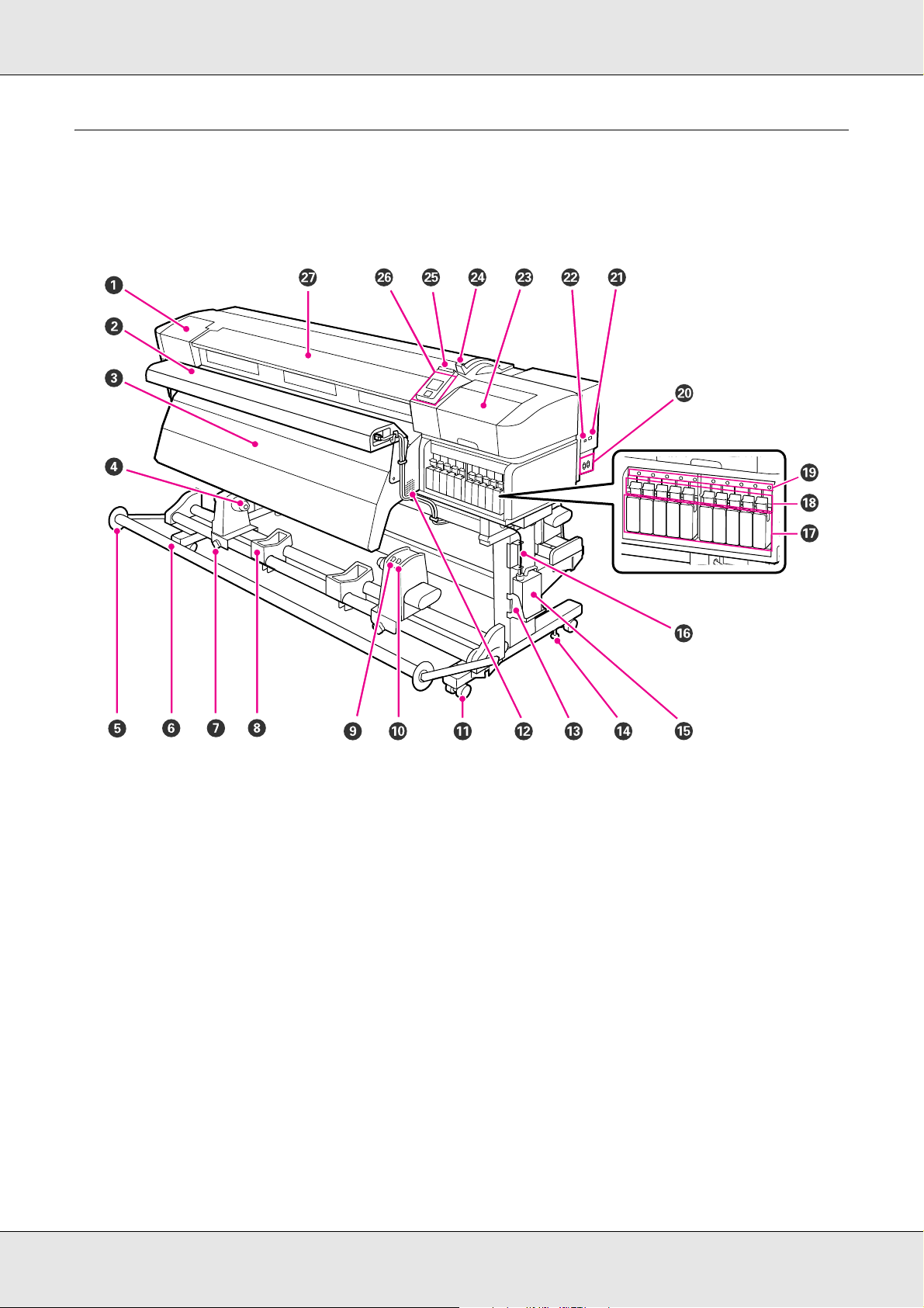
Front Section - S50675 and S70675
1 Maintenance cover (left)
Open this cover to clean the area around the print head. Normally closed when using the printer.
See “Cleaning Around the Print Head (Daily)” on page 137.
2 Additional print drying system
The additional print drying system can be used to rapidly dry ink after printing. Available separately for the S70675.
See the Additional Print Drying System Setup Guide.
3 After heater
The heater can be used to rapidly dry ink after printing.
See “Heating & Drying” on page 114.
4 Roll core holder
Place the roll core for media take-up on these holders. There are two holders: one on the left and one on the right.
See “Loading and Exchanging Media” on page 38.
5 Tensioner media guide
The tensioner media guide prevents the take-up roll from skewing when using the auto take-up reel unit. When not using the
auto take-up reel unit, move the guide out of the way toward both edges of the tensioner.
See “Using the Auto Take-up Reel Unit” on page 92.
Introduction 10
Page 11

6 Tensioner
The tensioner maintains tension to prevent the media sagging as it is taken up.
7 Roll core holder locking screw
The locking screws keep the roll core holders in place once they have been attached to the roll core. There are two locking
screws: one on the left and one on the right.
8 Roll support
Rest media temporarily on these supports when removing the take-up roll. There are two supports: one on the left and one on
the right.
9Auto switch
Use this switch to select the auto take-up direction. Choose Off to disable auto take-up.
10 Manual switch
Use this switch to select the manual take-up direction.AutoThe selected option takes effect when the Auto switch is in the Off
position.
11 Casters
There are two casters on each leg. Once installation is complete, the front casters should be kept locked while the printer is in
use.
12 Airflow vents
These vents allow air to flow into the printer. Do not obstruct these vents.
13 Waste ink bottle holder
Place the waste ink bottle in this holder.
14 Adjuster
The adjusters keep the printer in place. After installing the printer, keep it securely in place during use.
15 Waste ink bottle
Waste ink collects in this bottle.
Replace with a new waste ink bottle when the level approaches the line.
16 Waste ink tube
Waste ink is discharged from this tube. Be sure the end of this tube is in the waste ink bottle while the printer is in use.
17 Ink cartridges
Install all ink cartridges into each slot. Depending on the selected ColorMode, install the replacement cartridge or cleaning
cartridge.
18 Lock levers
Raise the levers to unlock the ink cartridges prior to removal. Lower the levers to lock the cartridges in place after insertion.
19 Cartridge check lamp
This lamp lights when an ink cartridge error occurs.
On An error occurred. Check the contents of the error on the control panel's screen.
Off No error.
20 AC inlet #1/AC inlet #2
Connects the power cable. Be sure to connect both cables.
21 LAN port
See “LAN Port” on page 19.
Introduction 11
Page 12

22 USB port
Connects the USB cable.
23 Maintenance cover (right)
Open this cover when performing regular maintenance. Normally closed when using the printer.
See “Cleaning Frequency” on page 129.
24 Media loading lever
After loading media, lower the media loading lever to keep the media in place. Raise the lever to release the media prior to
removal.
25 Alert lamp
This lamp lights or flashes when an error occurs.
On/Flashing An error occurred; the type of error is indicated by how the lamp lights or flashes. Check the contents of the
error on the control panel's screen.
Off No error.
26 Control panel
See “Control Panel” on page 20.
27 Front cover
Open when loading media, cleaning the inside of the printer, or removing jammed media. Normally closed when using the
printer.
Introduction 12
Page 13
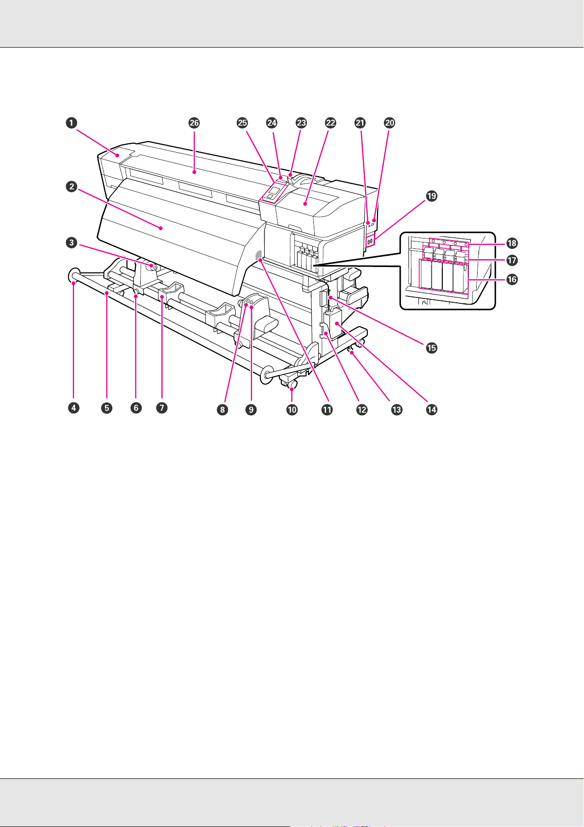
Front Section - S30675
1 Maintenance cover (left)
Open this cover to clean the area around the print head. Normally closed when using the printer.
See “Cleaning Around the Print Head (Daily)” on page 137.
2 After heater
The heater can be used to rapidly dry ink after printing.
See “Heating & Drying” on page 114.
3 Roll core holder
Place the roll core for media take-up on these holders. There are two holders: one on the left and one on the right.
See“Loading and Exchanging Media” on page 38.
4 Tensioner media guide
The tensioner media guide prevents the take-up roll from skewing when using the auto take-up reel unit. When not using the
auto take-up reel unit, move the guide out of the way toward both edges of the tensioner.
5Tensioner
The tensioner maintains tension to prevent the media sagging as it is taken up. See “Using the Auto Take-up Reel Unit” on
page 92.
6 Roll core holder locking screw
The locking screws keep the roll core holders in place once they have been attached to the roll core. There are two locking
screws: one on the left and one on the right.
Introduction 13
Page 14

7 Roll support
Rest media temporarily on these supports when removing the take-up roll. There are two supports: one on the left and one
on the right.
8Auto switch
Use this switch to select the auto take-up direction. Choose Off to disable auto take-up.
9Manual switch
Use this switch to select the manual take-up direction. The selected option takes effect when the Auto switch is in the Off
position.
10 Casters
There are two casters on each leg. Once installation is complete, the front casters should be kept locked while the printer is
in use.
11 Airflow vents
These vents allow air to flow into the printer. Do not obstruct these vents.
12 Waste ink bottle (tank) holder
Place the waste ink bottle in this holder.
13 Adjuster
The adjusters keep the printer in place. After installing the printer, keep it securely in place during use.
14 Waste ink bottle (tank)
Waste ink collects in this bottle.
Replace with a new waste ink bottle when the level approaches the line.
15 Waste ink tube
Waste ink is discharged from this tube. Be sure the end of this tube is in the waste ink bottle while the printer is in use.
16 Ink cartridges
Install all ink cartridges into each slot.
17 Lock levers
Raise the levers to unlock the ink cartridges prior to removal. Lower the levers to lock the cartridges in place after insertion.
18 Cartridge check lamp
This lamp lights when an ink cartridge error occurs.
On : An error occurred. Check the message on the control panel’s screen.
Off : No error.
19 AC inlet #1/AC inlet #2
Connects the power cable. Be sure to connect both cables.
20 LAN port
Connects the LAN cable.
21 USB port
Connects the USB cable.
22 Maintenance cover (right)
Open this cover when performing regular maintenance. Normally closed when using the printer.
See “Cleaning Frequency” on page 129.
Introduction 14
Page 15
23 Media loading lever
After loading media, lower the media loading lever to keep the media in place. Raise the lever to release the media prior to
removal.
24 Alert lamp
This lamp lights or flashes when an error occurs.
On/flashing : An error has occurred; the type of error is indicated by how the lamp lights or flashes. Check the message on
the control panel’s screen.
Off : No error.
25 Control panel
See “Control Panel” on page 20.
26 Front cover
Open when loading media, cleaning the inside of the printer, or removing jammed media. Normally closed when using the
printer.
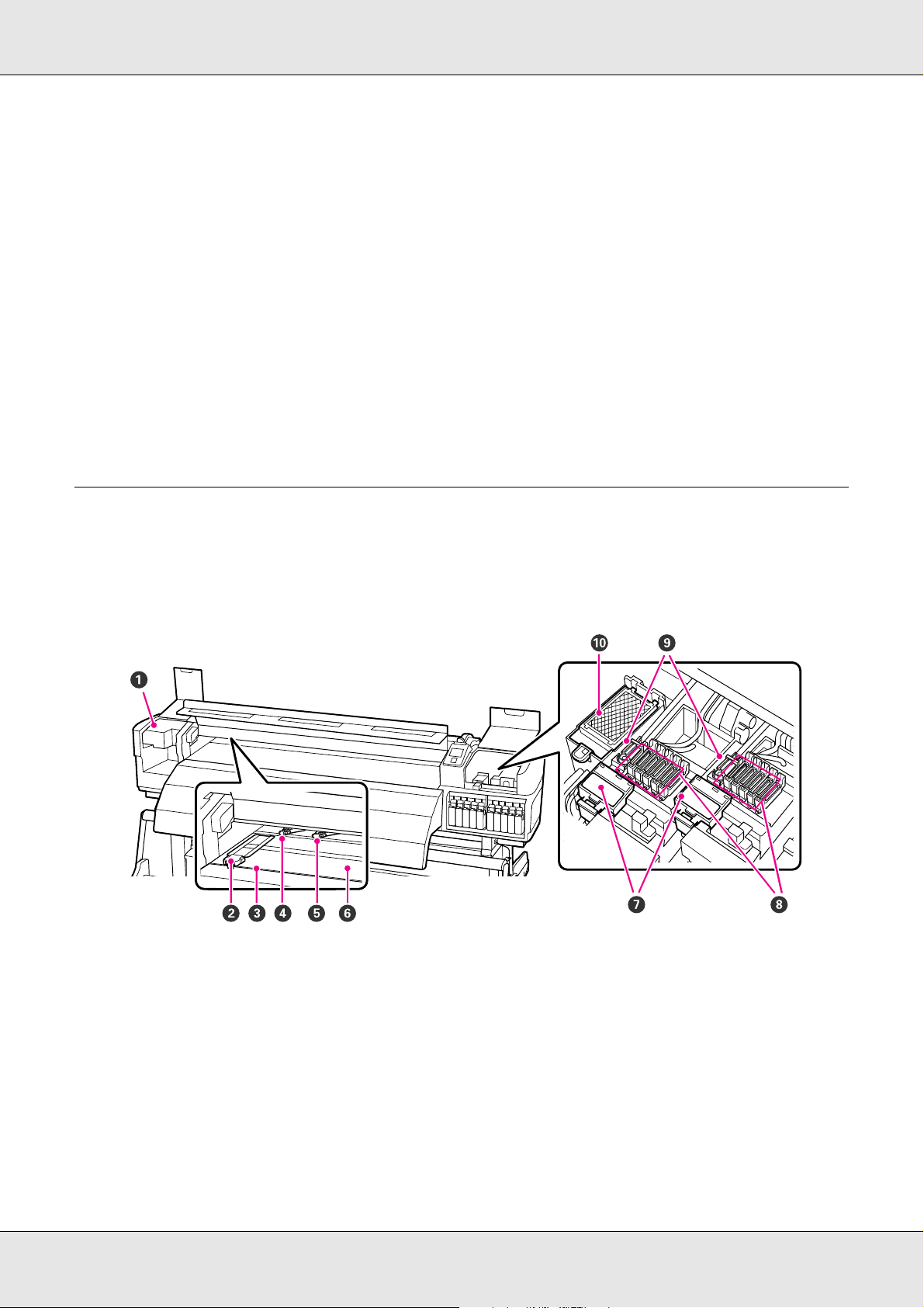
Inside - S70675 and S50675
Dirt on any of the following parts may reduce print quality. Regularly clean or exchange
these parts as described in the chapters listed in the reference sections below. The
illustration shows the S70675.
1 Print head
The print head prints by moving left and right while emitting ink. The print head on the left is Head 1, the print head on the
right Head 2. We recommend that you clean the area around this unit at the end of each workday.
See “Cleaning Around the Print Head (Daily)” on page 137.
2 Media holding plate (edge guide)
The media holding plates prevent the media riding up and keep fibers on the cut edge of the media from touching the print
head. Position the plates at either side of the media before printing.
See “Loading Media - S70675/S50675” on page 41 and “Loading Media - S30675” on page 65.
Introduction 15
Page 16

3 Cutter groove
Pass the blade of a cutter (not included) down this groove to cut media.
4 Pressure rollers (high)
There are ten rollers in total; the high pressure rollers are the two on the outside edges. They press down on the edges of the
media when transparent or white film is used and during ink layering.
See “Positioning the Pressure Rollers and Media (S70675, S50675)” on page 40.
See “Cleaning Inside the Printer (Daily)” on page 155.
5 Pressure rollers (low)
There are ten rollers in total; all of which are low pressure rollers apart from the two on the outside edges. They press down
on the media during normal printing (excluding transparent or white film and ink layering). The number used varies with the
width of the media.
See “Positioning the Pressure Rollers and Media (S70675, S50675)” on page 40.
See “Cleaning Inside the Printer (Daily)” on page 155.
6 Platen heater
The platen heater ensures that the ink adheres evenly.
See “Heating & Drying” on page 114.
See “Cleaning Inside the Printer (Daily)” on page 155.
7 Wiper cleaner
The wiper cleaner removes ink from the wiper. It is included in the maintenance kit and needs to be replaced about once
every three months.
See “Replacing the Wiper and Wiper Cleaner” on page 168.
8Caps
Except during printing, these caps cover the print head nozzles to prevent them drying out. We recommend that this unit be
cleaned at the end of each workday.
See “Regular Cleaning” on page 137.
9Wiper
The wiper removes ink from the print head nozzles. We recommend that this unit be cleaned once a week. It is included in the
maintenance kit and needs to be replaced about once every three months.
See “Regular Cleaning” on page 137.
See “Replacing the Wiper and Wiper Cleaner” on page 168.
10 Flushing pad
Ink is discharged onto this pad during flushing. It is It is included in the maintenance kit and needs to be replaced about once
every three months.
See “Replacing the Flushing Pad” on page 172.
Introduction 16
Page 17
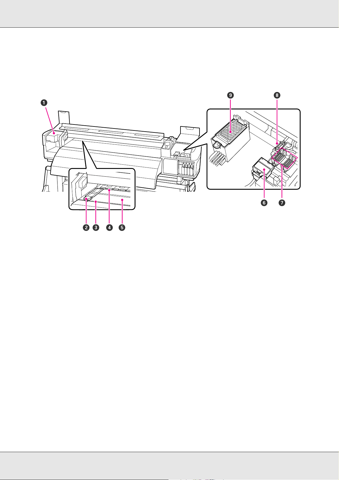
Inside - S30675
Dirt on any of the following parts may reduce print quality. Regularly clean or exchange
these parts as described in the chapters listed in the reference sections below.
1 Print head
The print head prints by moving left and right while emitting ink. We recommend that you clean the area around this unit at
the end of each workday. Make sure the print head is at the far left side of the printer before cleaning.
See “Cleaning Around the Print Head (Daily)” on page 137.
2 Media holding plate (edge guide)
The media holding plates prevent the media riding up and keeps fibers on the cut edge of the media from touching the print
head. Position the plates at either side of the media before printing.
See “Loading Media - S30675” on page 65.
3Cutter groove
Pass the blade of a cutter (not included) down this groove to cut media.
4 Pressure rollers
These rollers press down on the media during printing.
See “Cleaning Inside the Printer (Daily)” on page 155.
5 Platen heater
The platen heater ensures that the ink adheres evenly.
See “Heating & Drying” on page 114.
See “Cleaning Inside the Printer (Daily)” on page 155.
6 Wiper cleaner
The wiper cleaner removes ink from the wiper. It is included in the maintenance kit and needs to be replaced about once every
three months (or more often, depending on usage).
See “Cleaning the wiper cleaner and wiper rail (daily)” on page 148.
Introduction 17
Page 18
7Caps
Except during printing, these caps cover the print head nozzles to prevent them from drying out. We recommend that the caps
be cleaned at the end of each workday.
See “Regular Cleaning” on page 137.
8Wiper
The wiper removes ink from the print head nozzles. We recommend that this unit be cleaned at the end of each workday. It is
included in the maintenance kit and needs to be replaced about once every three months (or more often, depending on
usage).
See “Regular Cleaning” on page 137.
See “Cleaning the wiper cleaner and wiper rail (daily)” on page 148.
9Flushing pad
Ink is discharged onto this pad during flushing. It is included in the maintenance kit and needs to be replaced about once every
three months (or more often, depending on usage).
See “Replacing the Flushing Pad” on page 172.
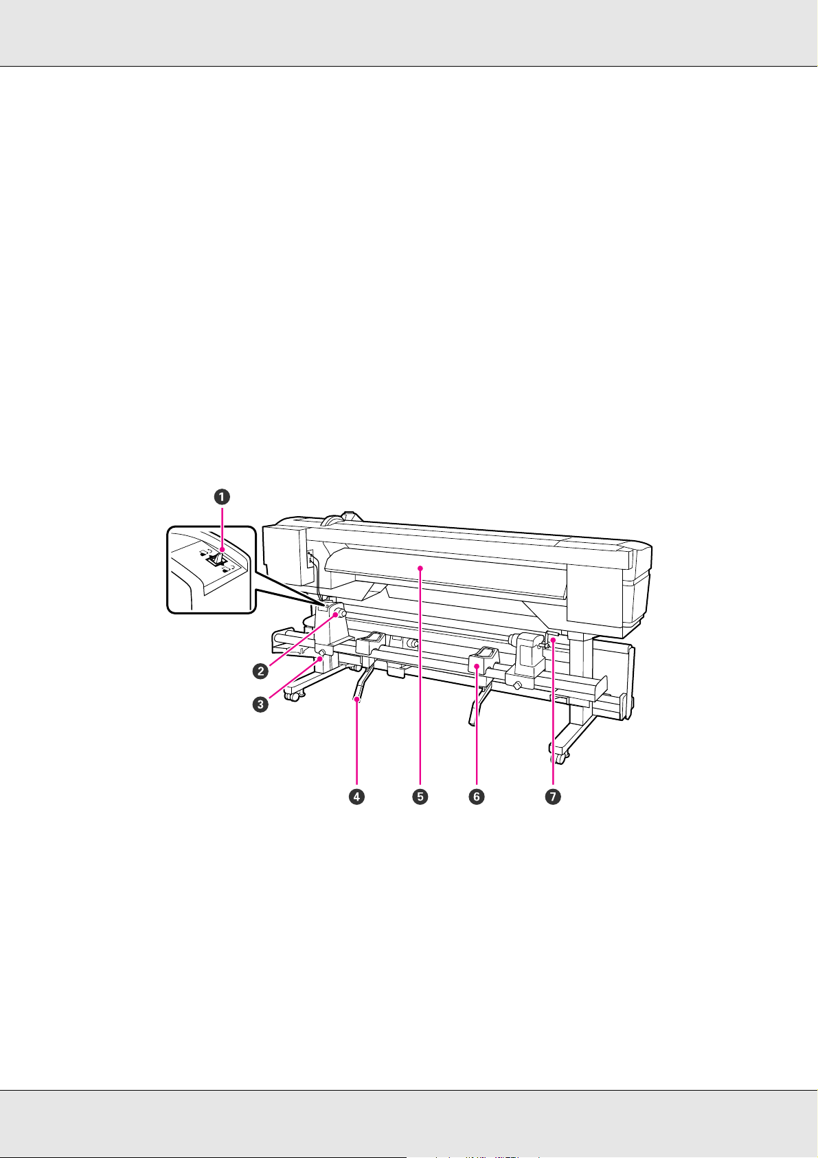
Back
1Drive switch
The drive switch is used to feed the media during loading and to rewind the media for replacement.
2 Roll holder
Place media on these holders. There are two holders: one on the left and one on the right.
3 Roll holder fixing screw
These screws fix the roll holders in place once the media has been installed. There are two screws: one on the left and one on
the right.
Introduction 18
Page 19
4 Epson LiftAssist lever
If the media to be mounted on the roll holders seems heavy, use these levers to raise the media effortlessly to the level of the
roll holders. There are two LiftAssist levers: one on the left and one on the right.
5Pre-heater
Heats the media before printing so that the print area is not subject to sudden changes in temperature.
6 Roll support
Rest media on these supports before placing it on the roll holders. There are two supports: one on the left and one on the right.
7Handle
After placing media on the right roll holder, rotate the handle to press the holder and apply pressure to the roll core.
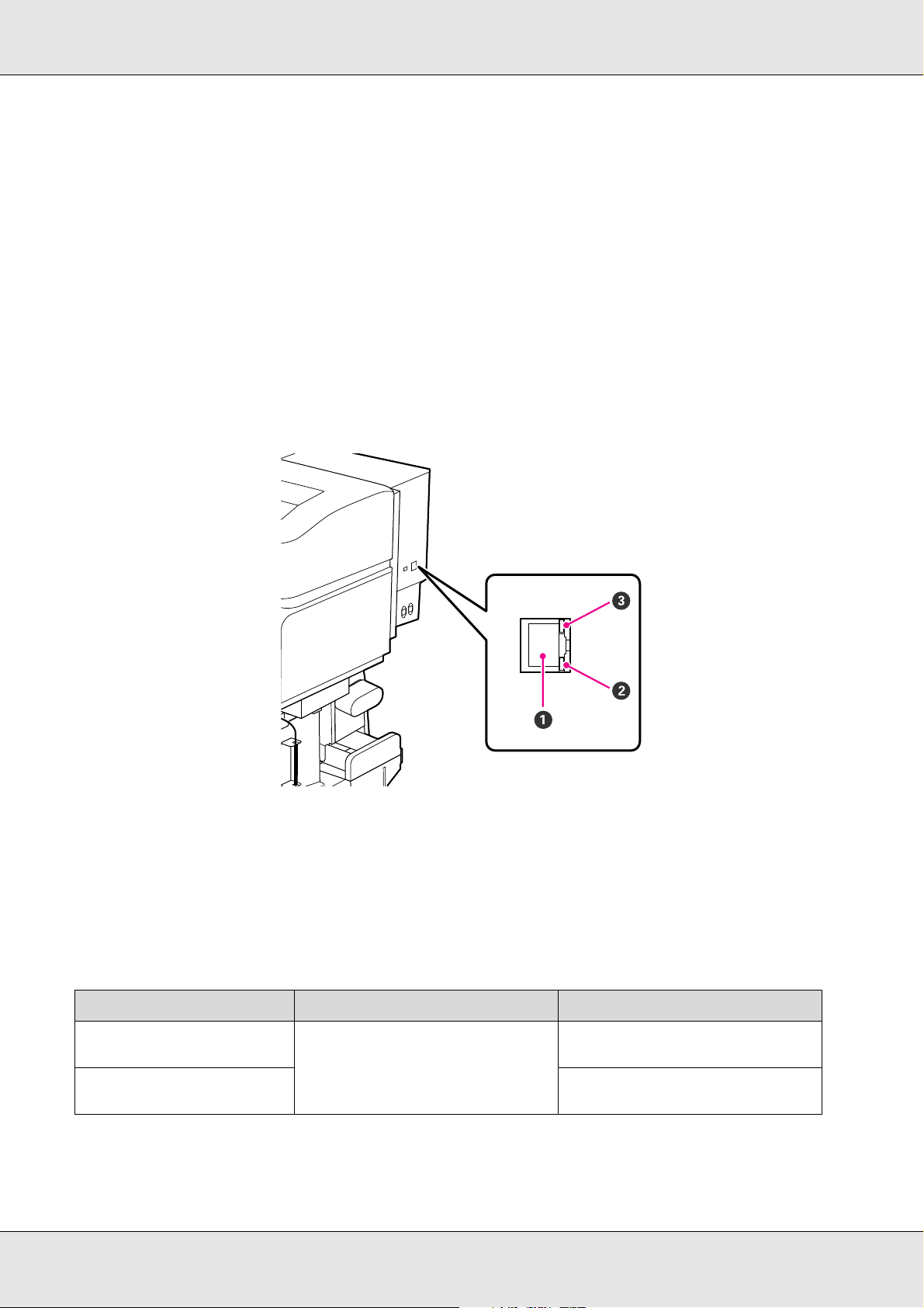
LAN Port
1RJ-45 connector
Connects the LAN cable. Use a shielded twisted pair cable (category 5 or higher).
2 Data lamp
The data lamp shows connection status and indicates whether the printer is receiving data.
3 Status lamp (green/red)
The status lamp indicates network connection speed.
Data lamp Status lamp (green/red) Status
On On (green) The printer is connected using a
1000base-T connection.
Flashing The printer is receiving data over a
1000base-T connection.
Introduction 19
Page 20
Data lamp Status lamp (green/red) Status
On On (red) The printer is connected using a
100base-TX connection.
Flashing The printer is receiving data over a
100base-TX connection.
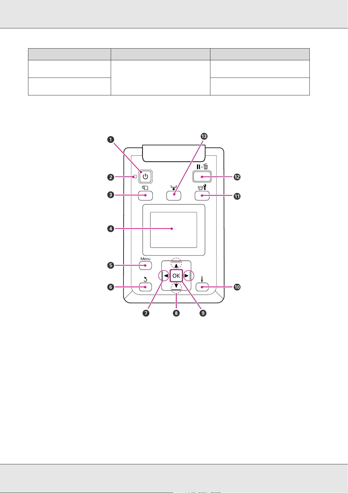
Control Panel
1 P button (power button)
Turns the power on and off.
2 P light (power light)
The printer's operational status is indicated by a lit or flashing light.
On : The power is on.
Flashing : The printer is receiving data or performing head cleaning or other operations during shut-down.
Off : The power is off.
Introduction 20
Page 21

3 M button (media setup button)
Press this button to display the Media Setup menu, which contains such items as Media Remaining, Select Media,
Customize Settings, and Print Media List. This button is disabled during printing.
See “The Media Setup Menu” on page 203.
4 Display
Displays the printer's status, menus, error messages, and so on. See “Understanding the Display” on page 22.
5 Menu button
Press this button to display menus. See “Using the Control Panel Menu” on page 198.
6 y button (back button)
Press this button to exit to the previous menu when options are displayed. See “Menu Operations” on page 198.
7 l/r buttons (left and right arrow buttons)
Use to position the cursor when performing such tasks as entering a Setting Name or IP Address in the setup menu.
8 u/d buttons (media feed buttons)
When the media loading lever is in a lowered position and the d button is pressed, media is fed. If the u button is pressed,
media is rewound. This occurs regardless of the way the loaded media is rolled. Press and hold the d button while at an
adjustment, check pattern, or media feed screen to feed the media the maximum length (103 cm [40.6 in]) into the printer.
Keep the u button pressed to rewind the media up to 25 cm (9.8 in.).
Note that when the u button is used to rewind, the media will stop when its edge reaches the starting print position. Rewind
can be resumed by releasing the button and then pressing it again.
When the media loading lever in a raised position, the button to rewind media depends on how the loaded media is rolled.
Printable Side Out: Press the u button.
Printable Side In: Press the d button.
Keep the button pressed to rewind the media up to 25 cm (9.8 in.).
When the menus are displayed, these buttons can be used to select menu items and options. See “Menu Operations” on page
198.
9OK button
Pressing this button when a menu item is highlighted displays options for the selected item.
Pressing this button when an option is highlighted selects the highlighted item or performs the selected operation.
When an alarm sounds, press the button to turn off the alarm.
Introduction 21
Page 22
10 button (heating and drying button)
Pressing this button displays the Heating & Drying menu, where you can adjust the Heater Temperature. If the optional
additional print drying system is attached, you can also adjust Additional Dryer settings. These options can be adjusted
during printing.
See “Heating & Drying” on page 114.
11 # button (maintenance button)
Pressing this button displays the Maintenance menu, which contains such items as Nozzle Check, Cleaning, Head Washing,
Head Maintenance, and Waste Ink Counter. This button is disabled during printing.
See “The Maintenance Menu” on page 211.
12 W button (pause/cancel button)
The printer enters pause status if this is pressed while printing. To release the pause status, press the W button again, or
select Pause Cancel on the screen and then press the Z button. To cancel print jobs being processed, select Job Cancel on
the screen and then press the Z button.
Pressing this button when menus are displayed closes the menus and returns the printer to ready status.
13 button (media feed button)
When the printer is in the ready state, you can feed the media to the cut position by pressing this button and then Z.
See “Cutting media” on page 88.
When printing is in progress, you can use this button to adjust media feed.
See “Feed Adjustment” on page 117.
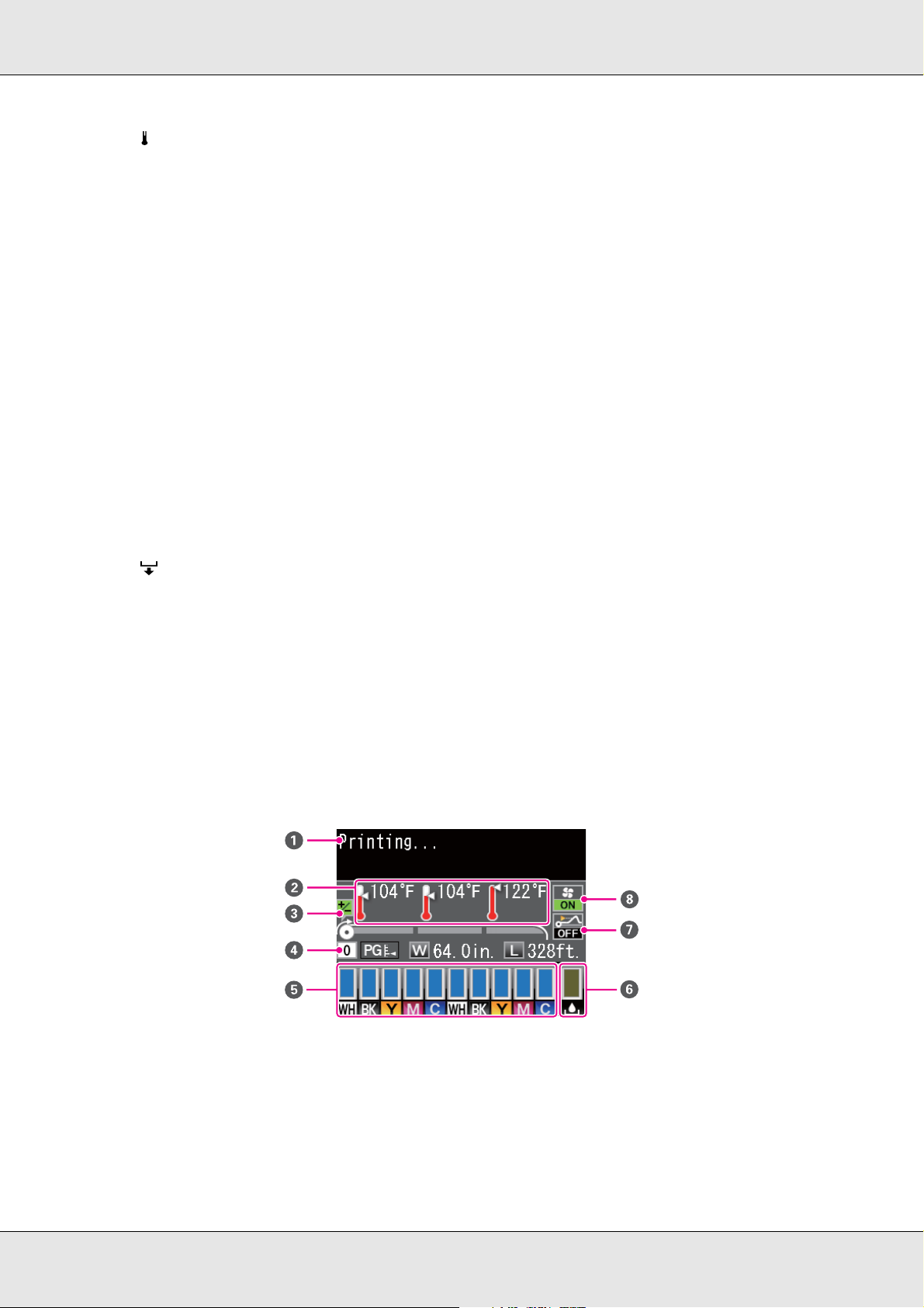
Understanding the Display
The following illustration shows the display for the S50675.
1Messages
Displays the printer's status, operation, and error messages.
See “When a Message Is Displayed” on page 215.
Introduction 22
Page 23
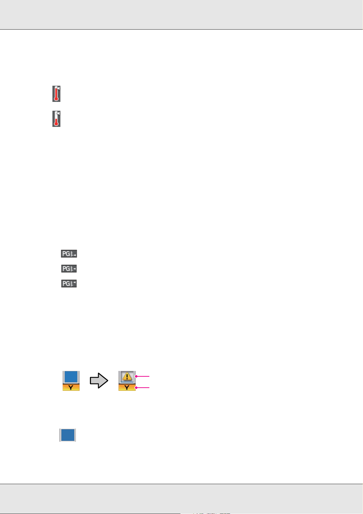
2 Heater temperature
1
2
From left to right, this display shows the temperature settings for the pre-heater, platen heater, and after heater. The
thermometer icons give a rough indication of the current temperatures of the heaters.
: The heater has reached the selected temperature.
: The heater has not reached the selected temperature.
3 Feed adjustment information during printing
This information is displayed when the adjustment value is specified during printing.
See “Feed Adjustment” on page 117.
4Media info
From left to right, this display shows the selected media, platen gap, media width, and media remaining.
If a media setting bank number created with this printer is selected as the print media, the number (from 1 to 30) will be
displayed. When RIP Settings is selected, 0 will be displayed.
The selected platen gap is shown as follows:
:1.5
:2.0
:2.5
The media remaining is not displayed if Off is selected for Remaining Setup in the Media Remaining menu.
See “The Media Setup Menu” on page 203.
5Ink cartridge status
Displays the approximate level of remaining ink and the current status. When ink runs low or an error occurs, the display
changes as shown below:
Normal Warning or error
1 Status indicators
The ink cartridge status is indicated as follows:
Ready to print. The height of the indicator changes with the level of ink remaining.
:
Introduction 23
Page 24
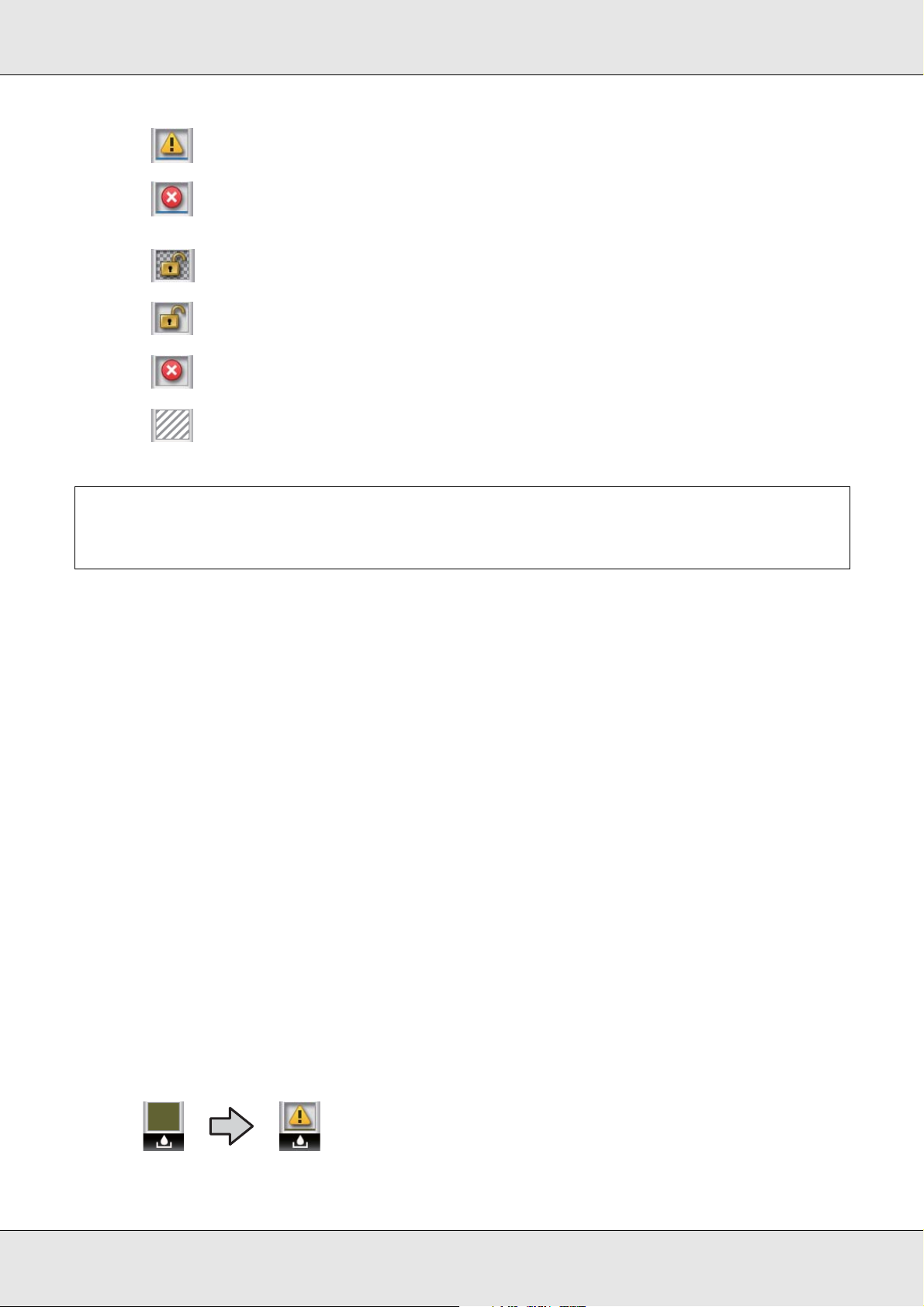
Ink is low. You need to prepare a new ink cartridge.
:
The level of ink remaining has reached the limit; replace with a new cartridge. When using spot
:
color inks, replace the ink cartridge promptly. If the old cartridge is not replaced, the print head
or other parts may be damaged.
The ink cartridge is not locked. Lower the lock lever to engage the lock.
:
No ink cartridge is inserted. Insert the ink cartridge and lower the lock lever to engage the lock.
:
An error occurred. Check the message on the screen, and clear the error.
:
A cleaning cartridge is installed. The height of the indicator shows the amount of cleaning liquid
:
remaining in the cartridge in three levels.
Note:
You can also check the level of ink remaining using the Ink Level option in the menus. See “The
Ink Level Menu” on page 212.
2 Ink color codes
BK : Black
Y : Yellow
M : Magenta
C : Cyan
MS Metallic Silver
LK Light Black
OR+ Orange Plus
LC Light Cyan
LM Light Magenta
WH White
6 Waste ink bottle status
Displays the approximate amount of space available in the waste ink bottle. The display changes as shown below when the
waste ink bottle is nearly full or an error occurs .
Normal Warning or error
Introduction 24
Page 25
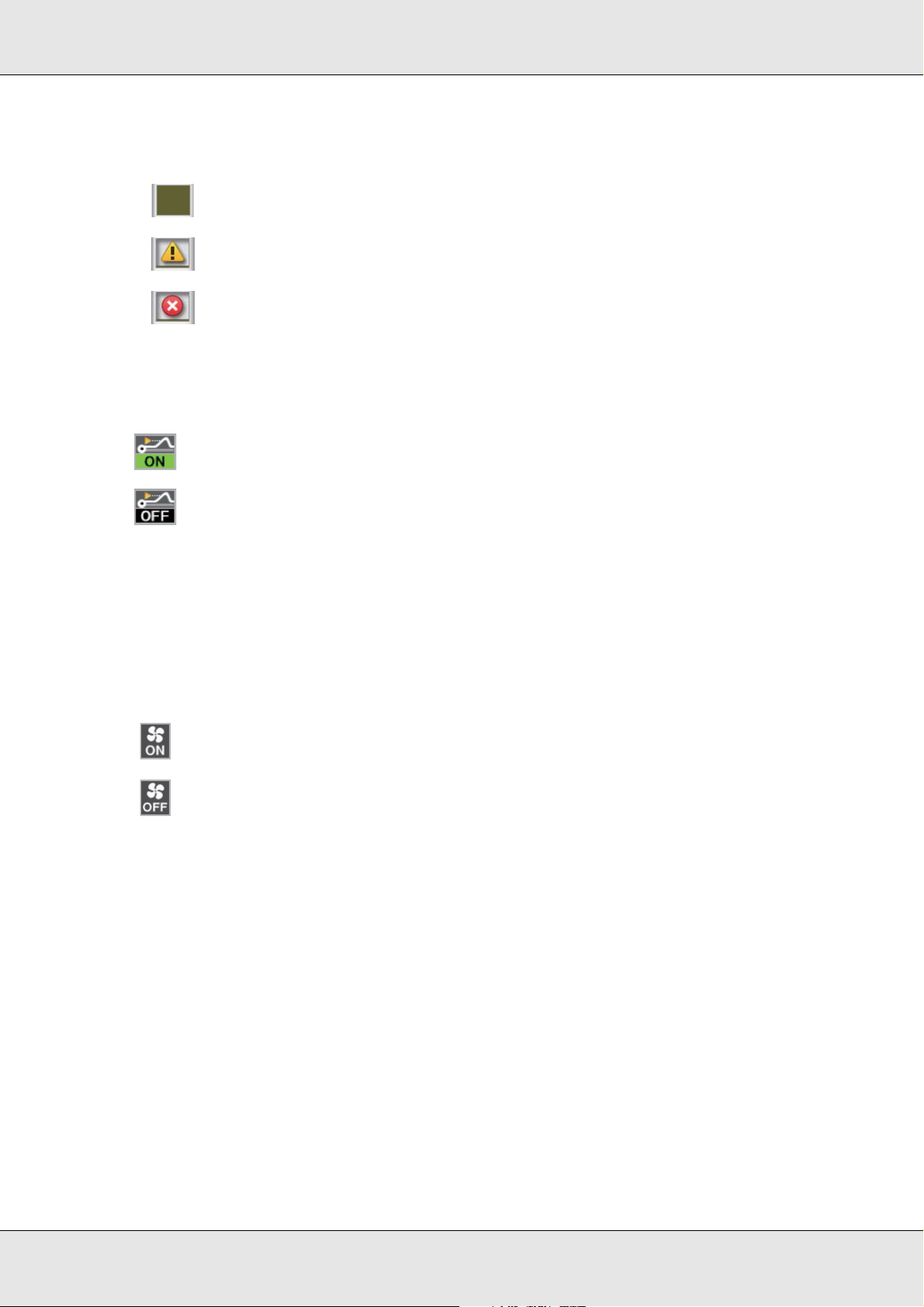
Status indicators
The status of the waste ink bottle is shown as follows:
No error. The indicator changes to show the amount of space available.
:
The waste ink bottle is almost full. Ready a new waste ink bottle.
:
The waste ink bottle is full. Replace with a new waste ink bottle.
:
7 Media rise detection status
This is displayed by the S50675 only.
: The printer checks whether the media rises during printing.
: The printer does not check whether the media rises during printing.
See the “The Maintenance Menu” on page 211.
8 Additional print drying system status (system included with the S50675 and optional for other
models)
This display shows settings for the optional additional print drying system.
No icon : Not installed, or it is not installed correctly.
The drying fan is enabled.
:
The drying fan is not enabled. To start the fan, select Additional Dryer for On in the setup menu.
:
See “Heating & Drying” on page 114.
Introduction 25
Page 26

Features
This wide-format color ink jet printer supports roll media up to 1626 mm (64 inches) in
width. The main features of this printer are described below.
Realizing High Productivity
Triple heaters
The three heaters listed below support improved productivity and print quality.
The pre-heater: Warms media before printing to protect the print area from sudden
changes in temperature.
The platen heater: Ensures that the ink adheres evenly.
The after heater: Can be used to rapidly dry ink after printing.
Media feeding unit accommodates high-capacity rolls
The standard media feeding unit can handle high-capacity rolls with external diameters of
up to 250 mm (9.8 inches) and weights of up to 40 kg (88.2 lb), ensuring that media require
less frequent replacement.
With the optional heavy roll media system, the printer can handle even larger 80 kg (176.4
lb) rolls with external diameters of 300 mm (11.8 inches).
Auto take-up reel unit comes standard
The auto take-up reel unit automatically takes up printed media cleanly, with no wrinkles.
You’ll find it comes in handy for banner printing, high-volume print jobs, and continuous
overnight printing.
High-capacity ink cartridges
The printer uses high-capacity, 700 ml ink cartridges (white cartridges 600 ml, metallic
silver cartridges 350 ml) to ensure productivity, reducing the need for frequent ink cartridge
replacement.
High-speed printing
The S50675 is equipped with two heads for faster printing. High speeds are supported by
using two cartridges for each color of ink.
Introduction 26
Page 27

High speed dryer available
The high speed dryer (included with the S50675; optional with other models) can be used
for increased drying performance and improved productivity. It is recommended when
using the S70675 in 10 color mode, as the white and metallic silver inks are slow to dry.
High Print Quality
Smooth tone gradations, high-fidelity color reproduction
The S70675 is equipped for light-colored inks (light black, light cyan and light magenta),
reducing grain for continuous tone gradation, while the use of orange ink increases the
color gamut for high-fidelity color reproduction. It is capable of print quality of a level
sufficient for car wraps and indoor display advertising that can be inspected at close range.
Support for white and metallic silver inks
A variety of print effects are available when using the S70675 with white and metallic silver
inks or the S50675 with white ink. The white ink is high opacity, making it suitable for
masking on transparent media (window graphics). Other inks can be printed over white or
metallic silver inks (ink layering), preventing color inks showing through and allowing for a
variety of metallic colors.
When using spot color inks, see “Spot Color Inks” on page 35.
Superior Ease of Use
Easy media installation and take up
The roll and roll core holders require no spindles, eliminating the need to attach spindles
before installing media. Just bring the media to the printer and install it directly. Never
having to juggle long spindles makes installing media a snap even where space is limited.
In addition to roll supports that give you a place to rest media during installation, the printer
offers lift levers that allow heavy media to be effortlessly raised to the level of the roll
holders.
Virtually odorless solvent ink
The distinctive odor of solvent-based inks has been reduced with our solvent inks. This not
only improves the work environment during printing but ensures that items intended for
indoor display can be exhibited in any venue.
Introduction 27
Page 28

Media rise detection
The S50675 is equipped with a system for detecting media rise during printing. If the media
rises during printing, printing will stop to prevent the media coming into contact with the
print head. Stopping printing avoids printing errors and prevents waste of ink and media.
Ease of maintenance
Print quality can only be ensured through daily maintenance, and the design of this printer
leaves plenty of space for maintenance.
E-Mail error/warning notification
The EpsonNet Config with Web Browser system built into the printer’s network interface
offers e-mail notification. Once configured for e-mail notification, the printer will send errors
and warnings to selected e-mail addresses, ensuring peace of mind when the printer is left
unmanned during overnight operation and in other similar situations.
Lamp and alarm error alerts
When an error occurs, a alarm will sound and the alert lamp will light. The large alert lamp
is highly visible, even at a distance.
A alarm sounds simultaneously to prevent time wasted while stoppages due to errors go
unnoticed.
High-speed USB/Gigabit Ethernet
The printer comes equipped with high-speed USB and 100 Base-TX/1000 Base-T network
interfaces.
Introduction 28
Page 29
Notes on Usage and Storage
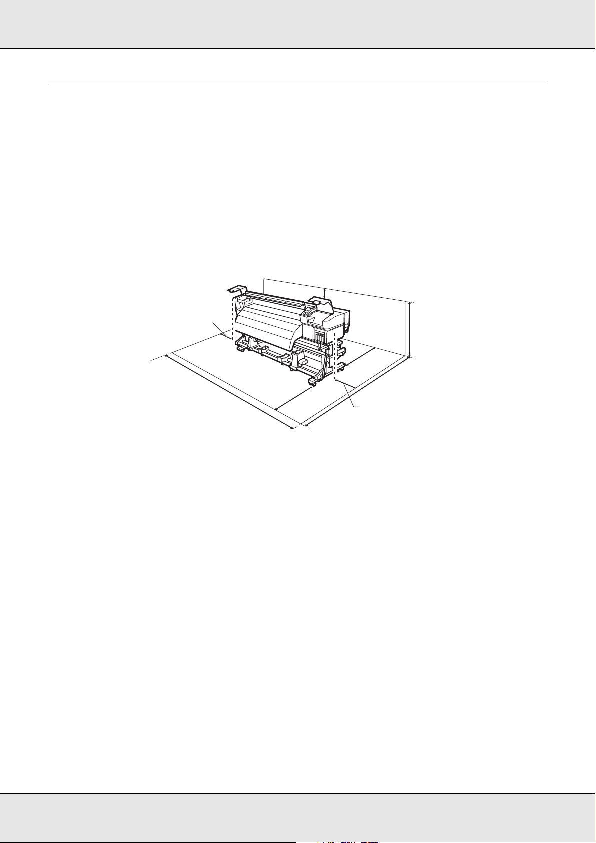
100 mm (3.9 in.)
500 mm (19.7 in.)
3620 mm (142.5 in.)
500 mm (19.7 in.)
2903 mm
(114.3 in.)
1750 mm
(68.9 in.)
1000 mm
(39.4 in.)
1
0
0
0
m
m
(3
9
.
4
i
n
.
)
In this document, white and metallic silver ink are called “spot color ink.”
Installation Space
Make sure that you secure the following space, clear of any other objects, so that paper
ejection and consumable replacement are not obstructed.
For the external dimensions of the printer, see “Specifications” on page 242.
Notes When Using the Printer
Note the following points when using this printer to avoid breakdowns, malfunctions, and
print quality decline.
Additional precautions are required for white and metallic silver inks. See “Spot Color Inks”
on page 35.
❏ When using the printer, observe the operating temperature and humidity range
described in the “Specifications” on page 242.
Note, however, that the desired results may not be achieved if the temperature and
humidity are within the limits for the printer but not within those for the media. Be sure
the operating conditions suit the media. For more information, see the documentation
supplied with the media.
Also, when operating in dry areas, air conditioned environment, or under direct sunlight,
maintain the appropriate humidity.
Introduction 29
Page 30

❏ Avoid using the printer in locations with heat sources or locations that are exposed to
direct drafts from ventilators or air conditioners. The print head nozzles could dry out
and clog.
❏ Do not bend or tug the waste ink tube. Ink could spill inside or around the printer.
❏ Maintenance such as cleaning and replacement must be performed according to usage
frequency or at recommended intervals. Failure to perform regular maintenance could
result in loss of print quality. In the absence of the appropriate maintenance, continued
use could damage the print head.
See “Cleaning Frequency” on page 129.
❏ The print head may not be capped (the print head may not return to the right side) if the
printer is turned off when the media is jammed or an error has occurred. Capping is a
function for automatically covering the print head with a cap (lid) to prevent the print
head from drying out. In this case, turn on the power and wait until capping is performed
automatically.
❏ When the power is on, do not remove the power plug or cut the power at the breaker.
The print head may not be capped properly. In this case, turn on the power and wait
until capping is performed automatically.
❏ The print head is automatically cleaned at a fixed interval after printing to keep the
nozzle from clogging.
Be sure that the waste ink bottle is installed whenever the printer is on.
❏ As well as being expended during printing, ink is used during head cleaning and other
maintenance required to keep the print head in working order.
Introduction 30
Page 31

Notes When Not Using the Printer
If you are not using it, note the following points when storing the printer. If it is not stored
correctly, you may not be able to print properly the next time it is used.
Additional precautions are required for white and metallic silver inks. See “Spot Color Inks”
on page 35.
❏ If the printer will not be used for an extended period (and switched off), use cleaning
cartridges (available separately) and perform Pre-Storage Maintenance. Leaving the
heads unwashed causes permanent clogs. See “Long-Term Storage (Pre-Storage
Maintenance)” on page 189 for more information.
❏ If you do not print for a long time and do not perform pre-storage maintenance, turn the
printer on at least once every seven days.
If you do not print for a long time, the print head nozzles may become clogged. Head
cleaning will be performed automatically after the printer is turned on and started. Head
cleaning prevents clogged print heads and maintains print quality. Do not turn the
printer off until cleaning is complete.
❏ If you have not used the printer for a long time, check the print head for clogging before
you start printing. Perform head cleaning if the print head is clogged. See “Checking for
Clogged Nozzles” on page 181.
❏ The pressure rollers may crease media left in the printer. The media may also become
wavy or curled, causing jams or resulting in the media coming into contact with the print
head. Remove the media before putting the printer in storage.
❏ Store the printer after confirming that the print head has been capped (the print head is
positioned at the far right). If the print head is left uncapped for a long time, the print
quality may decline.
Note:
If the print head is not capped, turn the printer on, and then turn it off.
❏ Close all covers before placing the printer in storage. If you are not using the printer for
a long time, put an anti-static cloth or cover on the printer to prevent dust build-up. The
print head nozzles are very small, and they can become clogged easily if fine dust gets
on the print head, and you may not be able to print properly.
❏ When storing the printer, be sure that it is level; do not store it on an angle, on end, or
upside down.
Introduction 31
Page 32

Handling ink cartridges
Note the following points when handling ink cartridges to maintain good print quality.
Additional precautions are required for white and metallic silver inks. See “Spot Color Inks”
on page 35.
❏ Extra ink is required to fully charge the print head nozzles the first time the printer is
used; replacement cartridges will be needed earlier than usual.
❏ Store ink cartridges at room temperature in a location that is not exposed to direct
sunlight.
❏ Store ink cleaner at room temperature out of direct sunlight.
❏ To ensure print quality, use all the ink in the cartridge before the earlier of the following
dates:
❏ The expiration date shown on the ink cartridge packaging
❏ Six months after opening the ink cartridge package
❏ If you move ink cartridges from a cold place to a warm place, leave it at room
temperature for more than four hours before using the ink cartridge.
❏ Do not touch the ink cartridge IC chip. You may not be able to print properly.
❏ In 8 Color (Fixed) mode or 4C Mode, use replacement cartridges to fill all slots with
cartridges. In 8 Color (Unfixed) mode or 9 Color mode, use cleaning cartridges to fill all
slots with cartridges. You cannot print if any of the slots are empty.
❏ Do not leave the printer without ink cartridges installed. The ink in the printer will dry out
and the printer will not function as expected. Leave ink cartridges or replacement
cartridges in all slots even while you are not using the printer.
❏ Because the green IC chip contains the cartridge’s own information such as the
remaining ink level, you can still reinstall and use the ink cartridge after removing it from
the printer.
Introduction 32
Page 33

❏ Use a cleaning stick from the supplied maintenance kit to wipe ink from the ink supply
port of cartridges that have been removed from the printer before all the ink is used.
Dried ink on the supply port may cause ink leaks when the cartridge is reinserted and
used.
While cartridges are in storage, keep the ink supply ports free of dust. The ink supply
port has a valve in it so it does not need to be capped.
❏ Removed ink cartridges may have ink around the ink supply port, so be careful not to
get any ink on the surrounding area when removing the cartridges.
❏ To maintain the quality of the print head, this printer stops printing before ink cartridges
are completely expended.
❏ Although the ink cartridges may contain recycled materials, this does not affect printer
function or performance.
❏ Do not dismantle or remodel ink cartridges. You may not be able to print properly.
❏ Do not drop or knock cartridges against hard objects; otherwise, the ink may leak.
❏ With the exception of spot color inks, ink cartridges must be removed and shaken
thoroughly once every three weeks.
See “Replacing and Shaking Ink Cartridges” on page 163.
❏ Do not insert or remove replacement cartridges during printing.
Handling Media
Note the following when handling or storing media. Media that is in poor condition will not
produce good quality prints.
Be sure to read the documentation provided with each type of media.
Introduction 33
Page 34

Notes on handling media
❏ Do not fold the media or damage the printable surface.
❏ Do not touch the printable surface. Moisture and oils from your hands can affect print
quality.
❏ When handling media, hold it by both edges. We recommend wearing cotton gloves.
❏ Keep the media dry.
❏ Packaging materials can be used to store media and should not be thrown away.
❏ Avoid locations that are subject to direct sunlight, excessive heat, or humidity.
❏ When not in use, media should be removed from the printer, rewound, and inserted in
its original packaging for storage. Leaving media in the printer for extended periods
may cause it to deteriorate.
Handling media after printing
To maintain long lasting, high quality print results, note the following points.
❏ Do not rub or scratch the printed surface. If it is rubbed or scratched, the ink may peel
off.
❏ Do not touch the printed surface, as this may remove the ink.
❏ Make sure printouts are completely dry before folding or stacking, as otherwise
discoloration or other marks may appear where the prints touch. These marks will
disappear if the prints are immediately separated and dried but will become permanent
if the surfaces are not separated.
❏ Avoid direct sunlight.
❏ To prevent discoloration, display and store prints as instructed in the documentation
supplied with the media.
Introduction 34
Page 35

Spot Color Inks
Spot color inks may be sedimented (components settling to the bottom of the liquid) due to
ink characteristics. Sedimentation triggers tint unevenness in printing results or clogged
nozzles.
Before using spot color inks, take note of the following cautions.
❏ The printer provides a function (auto ink circulation) that automatically circulates inks in
the print head or tube at periodic intervals to prevent inks from being sedimented.
❏ When using this function, we recommend that you do not turn the printer off. If the
power is turned off, auto ink circulation is not performed at the appropriate times.
This causes irresolvable sedimentation, which results in damage. When not using
the printer for a long period of time, see “Long-Term Storage (Pre-Storage
Maintenance)” on page 189.
❏ To cancel auto ink circulation, press the W button while Circulating ink... is being
displayed on the control panel screen. However, it cannot be canceled while ink
circulation is required. If auto ink circulation is canceled to make prints using spot
color inks, tint unevenness may occur in printing results. To avoid cancellation of the
auto ink circulation process, we recommend that you perform Ink Circulation
before starting printing. See “The Maintenance Menu” on page 211.
❏ Spot color ink cartridges must be removed and thoroughly shaken once every 24 hours.
See “Shaking cartridges” on page 163.
❏ Spot color ink cartridges must be stored flat (laid on their sides). If the cartridges are
stored vertically, even shaking the cartridges before use may fail to dissolve the
materials that have sedimented in the ink during storage.
❏ When tint unevenness is detected in printing results, perform Ink Refresh from the
menu on the control panel. See “Ink Refresh” on page 188.
❏ Note the following when using ink layering.
❏ Use media at least 2% longer than specified in document size settings.
❏ Note that the auto take-up reel unit may not function as expected, causing a decline
in print quality.
❏ Some media do not support ink layering. For details, refer to the documentation
supplied with the media or contact the manufacturer.
Introduction 35
Page 36

Using the Supplied Software
Contents of the Software CD
The following applications are available on the supplied software CD. Install as required.
For information about these applications, see the on-line help for the application in
question.
Note:
❏ The supplied disk does not contain printer drivers. A software RIP is required for printing.
❏ The latest applications can be downloaded from the Epson website.
Software Name Summary
Epson LFP Remote Panel 2 Epson LFP Remote Panel 2 is used to update firmware from a computer and copy the media
settings bank created in the printer’s setup menu to a computer.
See “Starting Epson LFP Remote Panel 2” on page 36 and “Exiting Epson LFP Remote Panel 2” on
page 37.
Epson Drivers and utilities Install the Epson communications driver.
The Epson communications driver is required if the Epson LFP Remote Panel 2 is to be used to copy
media settings. It is not a printer driver. In addition, the software RIP may not display printer status
if the Epson communications driver is not installed when the printer is connected to a computer via
USB. See the software RIP documentation for more information on the status display.
Epson Network utility Install and launch a wizard that will help you enter IP addresses for a simple network connection.
EpsonNet Config With this software, you can configure various network settings for the printer from your computer.
This is useful as it allows you to enter addresses and names using the keyboard.
Starting Epson LFP Remote Panel 2
Launch Epson LFP Remote Panel 2 after confirming that the printer displays Ready.
1. The application can be launched using either of the following two methods.
❏ Double-click the Epson LFP Remote Panel 2 icon on the desktop. The Epson LFP Remote
Panel 2 icon is created when the application is installed.
❏ Click Start > All Programs (or Programs) > Epson LFP Remote Panel 2 > Epson LFP Remote
Panel 2.
2. Click the desired item in the Epson LFP Remote Panel 2 main window.
See Epson LFP Remote Panel 2 help for more information.
Introduction 36
Page 37

Exiting Epson LFP Remote Panel 2
Click Finish in the Epson LFP Remote Panel 2 main window.
Uninstalling Software
Important:
❏ Log in to an “Computer administrator” account (an account with Administrators group
privileges).
❏ Enter the administrator password when prompted and then proceed with the remainder of the
operation.
❏ Exit any other applications that may be running.
This section describes how to uninstall Epson LFP Remote Panel 2 and the Epson
communications driver.
1. Turn off the printer, and unplug the interface cable.
2. Go to the Control Panel and click Uninstall a program from the Programs category.
In Windows XP, go to the Control Panel and click Add or Remove Programs.
3. Select the software you want to remove and then click Uninstall/Change (or
Change/Remove).
Selecting the following deletes the Epson communications drivers:
❏ Epson SC-S70675 Series Comm Driver Printer Uninstall
❏ Epson SC-S50675 Series Comm Driver Printer Uninstall
❏ Epson SC-S30675 Series Comm Driver Printer Uninstall
To uninstall Epson LFP Remote Panel 2, select Epson LFP Remote Panel 2.
4. Select the target printer icon, and then click OK.
5. Follow the on-screen instructions to continue. When the delete confirmation message
appears, click Yes.
If you are reinstalling the Epson communications driver, restart the computer.
Introduction 37
Page 38

Chapter 2
Basic Operations
Loading and Exchanging Media
The process for loading media varies with the model of printer or type of media feeding unit
used. Choose the method suited to your particular setup.
Using the S70675 or S50675
Positioning of the pressure rollers depends on the printing type or media width. The media
loading process varies based on the positioning of the pressure rollers. Therefore, check
the positioning of the pressure rollers in advance.
See “Positioning the Pressure Rollers and Media (S70675, S50675)” on page 40 and
“Loading Media - S70675/S50675” on page 41.
Using the S30675
See “Loading Media - S30675” on page 65.
Notes on Loading Media
Whenever you attempt to load the media, check the following cautions beforehand.
For information on the media that can be used in the printer, see “Supported Media” on
page 235.
Caution:
❏ The heaters and media holding plates may be hot; observe all necessary precautions.
c
Failure to observe the necessary precautions could result in burns.
❏ Be careful not to trap your hands or fingers when opening or closing the front cover.
Failure to observe this precaution could result in injury.
❏ Do not rub your hands along the edges of the media. The edges of the media are sharp
and can cause injury.
❏ Because the media is heavy it should not be carried by one person.
Basic Operations 38
Page 39

Load media just before printing.
The pressure rollers may crease media left in the printer. The media may also become
wavy or curled, causing jams or resulting in the media coming into contact with the print
head.
Observe the following points when handling media:
If the following points are not observed when handling media, small amounts of dust and
lint may stick to the media surface and cause in ink drops in the print results.
❏ Do not place exposed media directly on the floor.
Media should be rewound and inserted in its original packaging for storage.
❏ Do not carry media with the media surface pressed against clothing.
Handle media in its individual packaging until just before loading the media in the
printer.
Do not load media if its right and left edges are uneven.
If the right and left edges of the roll are uneven, media feeding problems may cause the
media to move around during printing. Either rewind to align the edges or use a roll without
any issues.
Basic Operations 39
Page 40

Positioning the Pressure Rollers and Media (S70675, S50675)
Pressure rollers must be set in the correct position to obtain good print results.
Positioning of media
There are square holes to indicate the pressure roller positions on the rear side of the
printer.
Observe the following cautions when positioning media to ensure that the positioning of
pressure rollers is appropriate for the media width.
❏ Ensure that the left edge of the media always passes within the range of 1.
❏ The right edge of the media must pass within the squares of 2 through 8 according to
the media width.
* Transparent film, white film, and ink layering are not supported for these widths.
Basic Operations 40
Page 41

Pressure roller types
There are two types of pressure rollers. As shown below, the pressure roller to use
depends on the type of printing.
❏ For normal printing, use low pressure rollers . Note that the quantity of rollers to use
depends on the media width.
❏ When transparent or white film is loaded or during ink layering, use high pressure
rollers .
Note:
❏ When loading transparent or white film, low pressure rollers may leave traces in the print
area.
❏ During ink layering, the use of low pressure rollers will interfere with the ink la yering process.
Loading Media - S70675/S50675
Follow the steps below when using the supplied media feeding unit.
When the Heavy Roll Media Feeding Unit is installed, see “Using the optional heavy roll
media feeding unit” on page 53.
Using the standard media feeding unit
This section uses the S70675 to illustrate the process of loading media when the supplied
media feeding unit is installed.
Before loading media, be sure to read “Notes on Loading Media” on page 38.
Basic Operations 41
Page 42

1. Turn on the printer and wait until Load media appears on the screen.
Important:
When spot color inks are installed, circulation will be performed automatically to prevent ink
accumulating in the printer and causing clogs when the printer is not in use. Because
turning the printer off prevents automatic circulation from being performed, leading to
printer malfunction, we recommend that the printer not be turned off.
2. Open the front cover and move the media holding plates out of the way.
Important:
If the media holding plates are not moved out of the way, media insertion may fail or
damage may occur to the edge of the media.
Hold the tabs on the media holding plates and move the plates to the right and left sides
of the platen.
3. Loosen the roll holder fixing screws sufficiently and adjust the roll holders so that the
gap between the two is wider than the media.
Center the roll supports between the roll holders.
Basic Operations 42
Page 43

Important:
Printable side out
Printable side in
If the right holder handle shaft is not visible, rotate the holder forward until it stops. The
media can not be properly loaded if the handle shaft is not visible.
4. Place media on the roll support oriented according to how it is rolled (see below).
5. Align the left and right edges of the media with the set positions according to the media
width.
Basic Operations 43
Page 44

See “Positioning the Pressure Rollers and Media (S70675, S50675)” on page 40.
Note:
If the label with black squares is not in place, affix the label as described in the Setup
Guide.
6. Raise the lift lever on the left side of the printer to lift the media into position, then firmly
insert the roll holder.
If the roll has an outer diameter of less than 140 mm (5.5 inches), lift it manually and
place it on the roll holder. The roll core will not reach the holder when raised using the
lift lever.
Basic Operations 44
Page 45

7. Tighten the roll holder screw until the screw no longer turns to fix the roll holder in place.
8. Raise the lift lever on the right side of the printer to lift the media into position, then firmly
insert the roll holder.
If the roll has an outer diameter of less than 140 mm (5.5 inches), lift it manually and
place it on the roll holder.
Basic Operations 45
Page 46

9. To ensure the roll holder is inserted into the roll core sufficiently, push the center section
on the side of the roll holder toward the roll end twice.
Important:
If the roll holder is inserted into the roll core insufficiently, media will not be fed correctly
during printing because of slippage between the roll holder and roll core. This may cause
banding in the print results.
10.Tighten the roll holder screw until it no longer turns to fix the roll holder in place.
Basic Operations 46
Page 47

Important:
If the roll holder screw is loose, the roll holder may move during printing. This could cause
stripes and unevenness in the print results.
11.Rotate the handle until part A in the illustration below is fully inserted.
Important:
Once part A is hidden, do not turn the handle any further. Failure to observe this precaution
could damage the roll holder.
If part A is still visible even after the handle has been turned fully, rewind the handle.
Loosen the roll holder screw on the right side, and then restart from Step 9.
12.Raise the media loading lever.
Basic Operations 47
Page 48

13.Insert the media approximately 30 cm (12 inches) into the opening, then lower the
media loading lever.
I
14.Check that the edges of the media pass within the dimensions of the square that was
adjusted in step 5.
Example of media with a width of 64 inches:
Important:
Perform steps 13 to 5 in reverse order and repeat the loading process if the edges of the
media are not within the square holes. Do not attempt to reposition the roll holders while
they are inserted in the media.
Basic Operations 48
Page 49

15.Hold the center of the media and raise the media loading lever.
16.Pull the media straight to the center of the after heater.
❏ Do not pull the media with both hands. This could cause the media to skew or move
around.
❏ The labels on the after heater are not used when media is loaded. If it is adjusted
too forcefully, the media may move around or become loose.
17.Hold both sides of the pressure roller and move it while pressing it down.
Basic Operations 49
Page 50

Note:
To avoid getting grease on your skin, do not touch the shaft (gray part in the f igure) at the
top of the roller.
Normal printing
❏ Use low pressure rollers. Move the high pressure rollers right or left until they
contact the ends.
❏ We recommend setting the low pressure rollers within 5 mm (0.20 inch) of the
edges.
❏ Position the remaining low pressure rollers within the black square labels. There
may be extra low pressure rollers depending on the media width. Position the extra
low pressure rollers away from the black square labels.
When transparent or white film is loaded or during ink layering
❏ Use high pressure rollers only.
❏ We recommend positioning the rollers within 10 mm (0.39 inch) from the left and
right edges of the media.
❏ Position the low pressure rollers away from the black square labels.
Basic Operations 50
Page 51

18.When the media loading lever is lowered, the pressure rollers set at the black square
labels secure the media.
19.Position the media holding plates at both sides of the media.
Basic Operations 51
Page 52

While holding the tabs on both sides, move the plates to the edges of the media. Adjust
so that both edges of the media are aligned to the center of the row of round holes in
the plates.
Important:
❏ Do not use the media holding plates with media that is more than 0.4 mm (0.02 inch)
thick. The media holding plates could touch and damage the print head.
❏ Always position the plates so that the edges of the media are at the centers of the round
holes. Incorrect positioning causes banding (horizontal lines, tint unevenness, or
stripes).
❏ Move the media holding plates to the left and right edges of the platen when they are
not in use.
❏ Do not use the media holding plates if the sides of the printed media are smudged or
torn.
Basic Operations 52
Page 53

20.Close the front cover.
When using the auto take-up reel, see “Using the Auto Take-up Reel Unit” on page 92.
When not using the auto take-up reel, proceed to check the media and change settings.
See “Viewing and Changing Media Settings” on page 85.
Using the optional heavy roll media feeding unit
This section uses the S70675 to illustrate how to load media when the optional heavy roll
media feeding unit is installed.
Caution:
Because the media is heavy, it should not be carried by one person. When loading or
c
removing the media, use at least two persons. Using a lifter is recommended when
handling a media that is 40 kg (88.3 lb) or heavier.
The explanation that follows assumes that a lifter is used.
The following types of lifter can be used:
❏ Fork or platform thickness: 28 mm (1.10 inches) or less
❏ The fork or platform can be lowered to approximately 190 mm (7.5 inches) from the
floor.
Before loading, be sure to read “Notes on Loading Media” on page 38.
1. Turn on the printer and wait until Load media appears on the screen.
Important:
When spot color inks are installed, circulation will be performed automatically to prevent ink
accumulating in the printer and causing clogs when the printer is not in use. Because
turning the printer off prevents automatic circulation from being performed, leading to
printer malfunction, we recommend that the printer not be turned off.
2. Open the front cover and move the media holding plates out of the way.
Basic Operations 53
Page 54

Important:
If the media holding plates are not moved out of the way, media insertion may fail or
damage may occur to the edge of the media.
Hold the tabs on the media holding plates and move the plates to the right and left sides
of the platen.
3. Loosen the left and right roll holder fixing screws sufficiently and separate the roll
holders so that the gap between the two is wider than the media.
Important:
If the right holder handle shaft is not visible, rotate the holder forward until it stops. The
media can not be properly loaded if the handle shaft is not visible.
Basic Operations 54
Page 55

4. Temporarily place media on the lifter oriented according to how it is rolled (see below)
Printable side out
Printable side in
5. Align the left and right edges of the media with the set positions according to the media.
See “Positioning the Pressure Rollers and Media (S70675, S50675)” on page 40.
6. Align the media and the roll holders.
Note:
If the label with black squares is not in place, affix the label as described in the Setup
Guide.
Basic Operations 55
Page 56

Raise or lower the lifter until the media roll core is level with the roll holders.
7. Fully insert the left roll holder. Next, tighten the roll holder screw until the screw no
longer turns to fix the roll holder in place.
Basic Operations 56
Page 57

8. Fully insert the right roll holder.
9. To ensure the roll holder is inserted into the roll core sufficiently, push the center section
on the side of the roll holder towards the roll end twice.
Important:
If the roll holder is inserted into the roll core insufficiently, media is not fed correctly during
printing because of slippage between the roll holder and roll core. This may cause banding
in the print results.
Basic Operations 57
Page 58

10.Tighten the roll holder screw until the screw no longer turns to fix the roll holder in place.
Important:
If the roll holder screw is loose, the roll holder may move during printing. This could cause
stripes and unevenness in the print results.
11.Remove the lifter.
Basic Operations 58
Page 59

12.Rotate the handle until part A in the illustration below is fully inserted.
Important:
Once part A is hidden, do not turn the handle any further. Failure to observe this precaution
could damage the roll holder.
If part A is still visible even after the handle has been fully turned, rewind the handle.
Loosen the roll holder screw on the right side, and then restart from step 8.
13.Raise the media loading lever.
Basic Operations 59
Page 60

14.Insert the media approximately 30 cm (12 inches) into the opening, then lower the
media loading lever.
15.Check that the edges of the media pass within the dimensions of the square that was
adjusted in step 5.
Example of setting media with a width of 64 inches:
Important:
Perform Steps 14 to 5 in reverse order and repeat the loading process if the edges of the
media are not within the square holes. Do not attempt to reposition the roll holders while
they are inserted in the media.
Basic Operations 60
Page 61

16.Hold the center of the media and raise the media loading lever.
17.Pull the media straight to the center of the after heater.
❏ Do not pull the media with both hands. This could cause the media to skew or move
around.
❏ The labels on the after heater are not used when media is loaded. If it is adjusted
too forcefully, the media may move around or become loose.
18.Hold both sides of the pressure roller and move it while pressing it down.
Basic Operations 61
Page 62

Note:
To avoid getting grease on your skin, do not touch the shaft (gray part in the figure) at the
top of the roller.
Normal printing
❏ Use low pressure rollers. Move the high pressure rollers to the right or left until
they contact the ends.
❏ We recommend setting the low pressure rollers within 5 mm (0.20 inch) of the
edges.
❏ Position the remaining low pressure rollers within the black square labels. There
may be extra low pressure rollers depending on the media width. Position the
extra low pressure rollers away from the black square labels.
Basic Operations 62
Page 63

When transparent or white film is loaded or during ink layering
❏ Use high pressure rollers only.
❏ We recommend positioning the rollers within 10 mm (0.39 inch) from the left
and right edges of the media.
❏ Position the low pressure rollers away from the black square labels.
19.When the media loading lever is lowered, the pressure rollers on the black square
labels secure the media.
20.Position the media holding plates at both sides of the media.
Basic Operations 63
Page 64

While holding the tabs on both sides, move the plates to the edges of the media. Adjust
so that both edges of the media are aligned to the center of the round holes in the
plates.
Important:
❏ Do not use the media holding plates with media that is more than 0.4 mm (0.02 inch)
thick. The media holding plates could touch and damage the print head.
❏ Always position the plates so that the edges of the media are at the centers of the round
holes. Incorrect positioning causes banding (horizontal lines, tint unevenness, or
stripes).
❏ Move the media holding plates to the left and right edges of the platen when they are
not in use.
❏ Do not use the media holding plates if the sides of the printed media are smudged or
torn.
Basic Operations 64
Page 65

21.Close the front cover.
When using the auto take-up reel, see “Using the Auto Take-up Reel Unit” on page 92.
When not using the auto take-up reel, proceed to check the media and change settings.
See “Viewing and Changing Media Settings” on page 85.
Loading Media - S30675
Follow the steps below when using the supplied media feeding unit.
When the Heavy Roll Media Feeding Unit is installed, see “Using the optional heavy roll
media feeding unit” on page 75.
Using the standard media feeding unit
This section describes how to load media when the standard media feeding unit is
installed.
Before loading media, be sure to read “Notes on Loading Media” on page 38.
1. Press the P button, and wait until Load media appears on the screen.
2. Open the front cover, and move the media holding plates out of the way.
Important:
If the media holding plates are not moved out of the way, media insertion may fail or
damage may occur to the edge of the media.
Basic Operations 65
Page 66

Hold the tabs on the media holding plates and move the plates to the right and left sides
Printable side out
Printable side in
of the platen.
3. Loosen the roll holder fixing screws sufficiently and adjust the roll holders so that the
gap between the two is wider than the media.
Center the roll supports between the roll holders.
Important:
If the right holder handle shaft is not visible, rotate the holder forward until it stops. The
media can not be properly loaded if the handle shaft is not visible.
4. Place media on the roll support oriented according to how it is rolled (see below).
Basic Operations 66
Page 67

5. Align the left edge of the media with the position on the label.
If the label does not have the loading position, mark it on the label as instructed in the
Setup Guide.
6. Raise the lift lever on the left side of the printer to lift the media into position, then firmly
insert the roll holder.
If the roll has an outer diameter of less than 140 mm (5.5 inches), lift it manually and
place it on the roll holder. The roll core will not reach the holder when raised using the
lift lever.
Basic Operations 67
Page 68

7. Tighten the roll holder screw until the screw no longer turns to fix the roll holder in place.
8. Raise the lift lever on the right side of the printer to lift the media into position, then firmly
insert the roll holder.
If the roll has an outer diameter of less than 140 mm (5.5 inches), lift it manually and
place it on the roll holder.
Basic Operations 68
Page 69

9. To ensure the roll holder is inserted into the roll core sufficiently, push the center section
on the side of the roll holder towards the roll end twice.
Important:
If the roll holder is inserted into the roll core insufficiently, media will not feed correctly
during printing because of slippage between the roll holder and roll core. This may cause
banding in the print results.
10.Tighten the roll holder screw until the screw no longer turns to fix the roll holder in place.
Basic Operations 69
Page 70

Important:
If the roll holder screw is loose, the roll holder may move during printing. This could cause
stripes and unevenness in the print results.
11.Rotate the handle until part A in the illustration below is fully inserted.
Important:
Once part A is hidden, do not turn the handle any further. Failure to observe this precaution
could damage the roll holder.
If part A is still visible even after the handle has been turned fully, rewind the handle.
Loosen the roll holder screw on the right side, and then restart from Step 8.
12.Raise the media loading lever.
Basic Operations 70
Page 71

13.Insert the media approximately 30 cm (12 inches) into the opening, then lower the
media loading lever.
14.Confirm that the left edge of the media passes over the center of the square in the label
on the pre-heater.
Basic Operations 71
Page 72

Important:
Perform Steps 13 to 5 in reverse order and repeat the loading process if the left edge of the
media is not within the guides. Do not attempt to reposition the roll holders while they are
inserted in the media.
15.Hold the center of the media and raise the media loading lever.
16.Pull the media straight to the center of the after heater.
❏ Do not pull the media with both hands. This could cause the media to skew or move
around.
Basic Operations 72
Page 73

❏ The labels on the after heater are not used when media is loaded. If it is adjusted
too forcefully, the media may move around or become loose.
17.Lower the media loading lever to hold the media in place.
18.Position the media holding plates at both sides of the media.
Basic Operations 73
Page 74

While holding the tabs on both sides, move the plates to the edges of the media. Adjust
so that the edges of the media are aligned to the center of the round holes in the plates.
Important:
❏ Do not use the media holding plates with media that is more than 0.4 mm (0.02 inch)
thick. The media holding plates could touch and damage the print head.
❏ Always position the plates so that the edges of the media are at the centers of the
round holes. Incorrect positioning causes banding (horizontal lines, tint unevenness, or
stripes).
❏ Move the media holding plates to the left and right edges of the platen when they are
not in use.
❏ Do not use the media holding plates if the sides of the printed media are smudged or
torn.
Basic Operations 74
Page 75

19.Close the front cover.
When using the auto take-up reel, see “Using the Auto Take-up Reel Unit” on page 92.
When not using the auto take-up reel, proceed to check the media and change settings.
See “Viewing and Changing Media Settings” on page 85.
Using the optional heavy roll media feeding unit
This section describes how to load media when the optional heavy roll media feeding unit
is installed.
Caution:
Because the media is heavy, it should not be carried by one person. When loading or
c
removing the media, use at least two persons. Using a lifter is recommended when
handling a media that is 40 kg (88.2 lb) or heavier.
The explanation that follows assumes that a lifter is used.
The following types of lifter can be used:
❏ Fork or platform thickness: 28 mm (1.10 inches) or less.
❏ Fork or platform can be lowered to approx.190 mm (7.5 inches) from the floor.
Before loading media, be sure to read “Notes on Loading Media” on page 38.
1. Press the P button, and wait until Load media. appears on the screen.
2. Open the front cover, and move the media holding plates out of the way.
Important:
If the media holding plates are not moved out of the way, media insertion may fail or
damage may occur to the edge of the media.
Basic Operations 75
Page 76

Hold the tabs on the media holding plates and move the plates to the right and left sides
Printable side out
Printable side in
of the platen.
3. Loosen the left and right roll holder fixing screws and adjust the roll holders so that the
gap between the two is wider than the media.
Important:
If the right holder handle shaft is not visible, rotate the holder forward until it stops. The
media can not be properly loaded if the handle shaft is not visible.
4. Place the media on the lifter oriented according to how it is rolled (see below).
Basic Operations 76
Page 77

Move the lifter so that the left edge of the media matches the set position on the label.
If the label does not have the loading position, mark it on the label as instructed in the
Setup Guide.
5. Align the media and the roll holders.
Raise or lower the lifter until the media roll core is level with the roll holders.
Basic Operations 77
Page 78

6. Fully insert the left roll holder. Next, tighten the roll holder screw until the screw no
longer turns to fix the roll holder in place.
7. Fully insert the right roll holder.
Basic Operations 78
Page 79

8. To ensure the roll holder is inserted into the roll core sufficiently, push the center section
on the side of the roll holder towards the roll end twice.
Important:
If the roll holder is inserted into the roll core insufficiently, media will not feed correctly
during printing because of slippage between the roll holder and roll core. This may cause
banding in the print results.
Basic Operations 79
Page 80

9. Tighten the roll holder screw until the screw no longer turns to fix the roll holder in place.
Important:
If the roll holder screw is loose, the roll holder may move during printing. This could cause
stripes and unevenness in the print results.
10.Remove the lifter.
Basic Operations 80
Page 81

11.Rotate the handle until part A in the illustration below is fully inserted.
Important:
Once part A is hidden, do not turn the handle any further. Failure to observe this precaution
could damage the roll holder.
If part A is still visible even after the handle has been turned fully, rewind the handle.
Loosen the roll holder screw on the right side, and then restart from Step 7.
12.Raise the media loading lever.
P
Basic Operations 81
Page 82

13.Insert the media approximately 30 cm (12 inches) into the opening, then lower the
media loading lever.
14.Confirm that the left edge of the media passes within the square in the label on the
pre-heater.
Important:
Perform Steps 13 to 4 in reverse order and repeat the loading process if the left edge of the
media is not within the guides. Do not attempt to reposition the roll holders while they are
inserted in the media.
Basic Operations 82
Page 83

15.Hold the center of the media and raise the media loading lever.
16.Pull the media straight to the center of the after heater.
❏ Do not pull the media with both hands. This could cause the media to skew or move
around.
❏ The labels on the after heater are not used when media is loaded. If it is adjusted
too forcefully, the media may move around or become loose.
Basic Operations 83
Page 84

17.Lower the media loading lever to hold the media in place.
18.Position the media holding plates at both sides of the media.
While holding the tabs on both sides, move the plates to the edges of the media. Adjust
so that both edges of the media are aligned with the center of the round holes in the
plates.
Basic Operations 84
Page 85

Important:
❏ Do not use the media holding plates with media that is more than 0.4 mm (0.02 inch)
thick. The media holding plates could touch and damage the print head.
❏ Always position the plates so that the edges of the media are at the centers of the
round holes. Incorrect positioning causes banding (horizontal lines, tint unevenness, or
stripes).
❏ Move the media holding plates to the left and right edges of the platen when they are
not in use.
❏ Do not use the media holding plates if the sides of the printed media are smudged or
torn.
19.Close the front cover.
When using the auto take-up reel, see “Using the Auto Take-up Reel Unit” on page 92.
When not using the auto take-up reel, proceed to check the media and change settings.
See “Viewing and Changing Media Settings” on page 85.
Viewing and Changing Media Settings
The control panel displays the following information once the media is loaded.
This display can be used to view or change the following two options:
❏ Remaining Setup
Basic Operations 85
Page 86

On: The printer displays the amount of media remaining.
Off: The printer does not display the amount of media remaining.
When Remaining Setup is On, the printer will calculate the approximate amount of
media remaining based on the length of the roll and the amount used for printing and
display this information in the control panel. The display gives a rough idea of the
amount of media available before printing, making it easier to know when media
requires replacement.
In addition, a warning will be displayed when the amount of media remaining reaches a
specified level.
❏ Selected Media
Displays the parameters on which media settings are based as shown below.
RIP Settings: Media settings are based on those in the RIP.
XXXXXXXXXXXXXXXXXX: Media settings are based on those stored in the printer
in media settings bank No. 1.
Media settings banks can store a variety of settings for different media based on the
options selected in the Heater Temperature, Media Suction, Head Alignment, and other
menus. Up to 30 combinations of settings can be stored by assigning them to banks No.
1 to 30.
See “Saving Media Settings” on page 112.
1. Select an option.
To print at current settings, use the d/u buttons to select Keep Settings Above and
press the Z button. Proceed to Step 6.
To change settings, use the d/u buttons to select Change Settings and press the Z
button.
2. Select the items you want to change and press the Z button.
3. Select the desired option and press the Z button.
Basic Operations 86
Page 87

4. Press the y button to display the dialog shown in Step 2 and then press the y button
again.
5. After confirming that the settings are correct, use the d/u buttons to select Keep
Settings Above and press the Z button.
6. When the roll type selection screen appears, use the d/u buttons to select the roll type
that matches the loaded roll and press the Z button.
7. If On is selected for Remaining Setup, you will be prompted to enter the length of the
current media. Use the d/u buttons to choose a length between 1.0 and 999.5 m (3 and
3,300 feet) and press the Z button. You can set the length in 0.5 m increments. If the
display is in feet, lengths are given in increments of 1 foot.
The printer will display Ready after a brief pause, showing that it is ready to print. Transmit
the data to be printed from the computer.
Replacing and Removing Media
To replace or remove the media after printing, print the amount of media remaining, cut the
media, and remove the roll.
Printing the amount of media remaining
The printer displays the amount of media remaining and any media low warnings in the
control panel. This makes it possible to determine whether the media requires replacement
before printing.
The amount of media remaining can only be displayed if the correct length is entered when
the media is loaded.
You can print the amount of media remaining on the leading edge of the roll before it is
removed from the printer and then enter this number the next time the media is loaded for
accurate information on the amount remaining.
Note:
The printer does not calculate or display the amount of media remaining when Off is selected for
Remaining Setup in the setup menu. See “Viewing and Changing Media Settings” on page 85.
Basic Operations 87
Page 88

The following section describes how to print the amount of media remaining.
1. Confirm that the printer is ready to print.
2. Press the M button, select Media Remaining in the menu, and press the Z button.
3. Select Print Remaining Length and press the Z button.
4. Press the Z button to print the amount of media remaining.
Cutting media
Use a cutter (not included) to cut the media when printing is complete.
Basic Operations 88
Page 89

Caution:
The heaters and media holding plate may be hot; observe all necessary precautions.
c
Failure to observe the necessary precautions could result in burns.
When cutting media, be careful not to cut your fingers or hands with the cutter or other
blades.
1. After checking that the printer is ready, press the button and the Z button.
2. Check that the trailing edge of the printed media is fed to a position over the cutter
groove, and open the front cover.
If you have printed the amount of media remaining, press the u button to rewind the
media so that this information will remain on the roll after the media is cut.
Basic Operations 89
Page 90

When the auto take-up reel unit is used, raise the tensioner.
3. Open the front cover, and move the media holding plates out of the way. Hold the tabs
and move the plates to the right and left sides of the platen.
4. Cut the media with the cutter.
Pass the blade of the cutter down the cutting groove.
Basic Operations 90
Page 91

When the auto take-up reel unit is used, proceed to Step 5. Otherwise, proceed to Step
7.
5. Set the Auto switch to off. Take up the cut media completely by operating the Manual
switch according to how the media is rolled.
6. Remove the take-up roll. See “Removing the Take-up Roll (Using the Standard
Take-up Reel)” on page 107.
7. To remove the media, reverse the steps you followed to load it. See “Loading Media S70675/S50675” on page 41or “Loading Media - S30675” on page 65.
Important:
To finish the procedure on the S70675 or S50675, raise the media loading lever.
Otherwise, the pressure rollers will be deformed.
Basic Operations 91
Page 92

Using the Auto Take-up Reel Unit
The auto take-up reel unit automatically takes up media as it is printed, improving the
efficiency of unmanned operation.
The auto take-up reel unit for this printer can take up media in either of the following
directions.
Printed side out Printed side in
Taking-up with printed side out places the printed surface on the outside of the roll.
Taking-up with printed side in places the printed surface on the inside of the roll.
Follow the procedures below to attach the roll core to the auto take-up reel unit, and then
attach the media to the roll core depending on how the media is rolled.
The explanation that follows uses the supplied auto take-up reel unit for illustrative
purposes, but the same procedure can be followed when using the optional auto take-up
reel unit for heavy media (unless otherwise noted).
See “Attaching the Roll Core” on page 93, “Take up with the printed side facing out” on
page 97, or “Take up with the printed side facing in” on page 102.
Caution:
❏ Follow the instructions in the manual when loading media or roll cores or removing the
c
take-up roll.
Dropping media, roll cores, or take-up rolls could result in injury.
❏ Be sure that your hands or hair do not get caught in the auto take-up reel unit while it
is in operation.
Failure to observe this precaution could result in injury.
❏ Use a roll core that is longer than the width of the media. This allows the media to be
taken up without protruding from the core.
Basic Operations 92
Page 93

❏ Attach media to the roll core using the paper tape supplied. Using the paper tape
reduces take-up roll misalignment errors. When the tape has been completely used,
purchase commercially available paper tape (that is not easily stretched or cut) with a
width of 20 to 25 mm (about one inch).
❏ For ink layering, the auto take-up reel unit is not recommended (S70675 and S50675
only). Take-up may not be possible, or print quality may decline.
Attaching the Roll Core
Important:
When using the optional heavy roll media system and before starting this procedure, check
that the handle shaft of the unit on the left is visible. If the shaft is not visible, turn the
handle in the direction shown below unit it does not turn any more.
1. After confirming that the media is loaded correctly, press the d button until the leading
edge of the media reaches the roll core holder.
Important:
Always press the d button to feed the media as far as the roll core holder. If the media is
pulled by hand, the media may twist during take-up.
2. Loosen the roll core holder fixing screws at both sides and adjust the left roll core
holder.
Basic Operations 93
Page 94

Center the roll supports between the roll holders.
3. Align the right roll core holder with the right edge of the media and tighten the fixing
screw.
4. Cut the left and right corners of the media edges as shown below.
Basic Operations 94
Page 95

Cutting the media prevents feeding problems, such as the left and right corners of
media being folded and caught at the start of take-up. This process also allows the
media to stay centered on the core.
5. Insert the roll core onto the right holder.
6. Insert the left holder into the roll core.
Basic Operations 95
Page 96

❏ When using the standard roll media system, push the holder until part A shown in
the illustration below is fully inserted, and tighten the screw.
Important:
Stop when part A is no longer visible. The take-up reel unit may not function as
expected if the holder is inserted too far.
❏ When using the optional heavy roll media system, securely push the roll core holder
into the roll core using both hands, and then tighten the fixing screws. Rotate the
handle until part A in the illustration below is fully inserted.
Basic Operations 96
Page 97

Important:
Once part A is hidden, do not turn the handle any further. Failure to observe this
precaution could damage the roll core holder. If part A is still visible even after the
handle has been turned fully, rewind the handle. Then loosen the left roll core holder
fixing screw and reattach the roll core.
For the subsequent steps, see the next section or “Take up with the printed side facing in”
on page 102.
Take up with the printed side facing out
1. Cut the paper tape approximately 60 cm (24 inches) in length, and paste it
approximately in the center of the media using adhesive tape.
2. Hold down the u button until the tip of the tape reaches the center of the pipe.
Basic Operations 97
Page 98

3. Turn the paper tape over from the front of the roll core, and stick using adhesive tape.
Important
Attach the media to the take up roll core with the media in a taut state. If media is loose, it
may move around during take-up.
4. Flip the Auto switch to .
Basic Operations 98
Page 99

5. Lower the tensioner until it slightly touches the paper tape.
6. Continue holding down the d button until both edges of the media reach the paper core
and wrap around once or twice.
Basic Operations 99
Page 100

7. Position the right and left tensioner media guides until they slightly touch the media.
8. When loading banner media, attach three counter weights to both ends of the
tensioners.
Basic Operations 100
 Loading...