

Page 1
Setup Guide
Guía de instalación
Guia de instalação
EPSON® SureColor® S-Series
Page 2
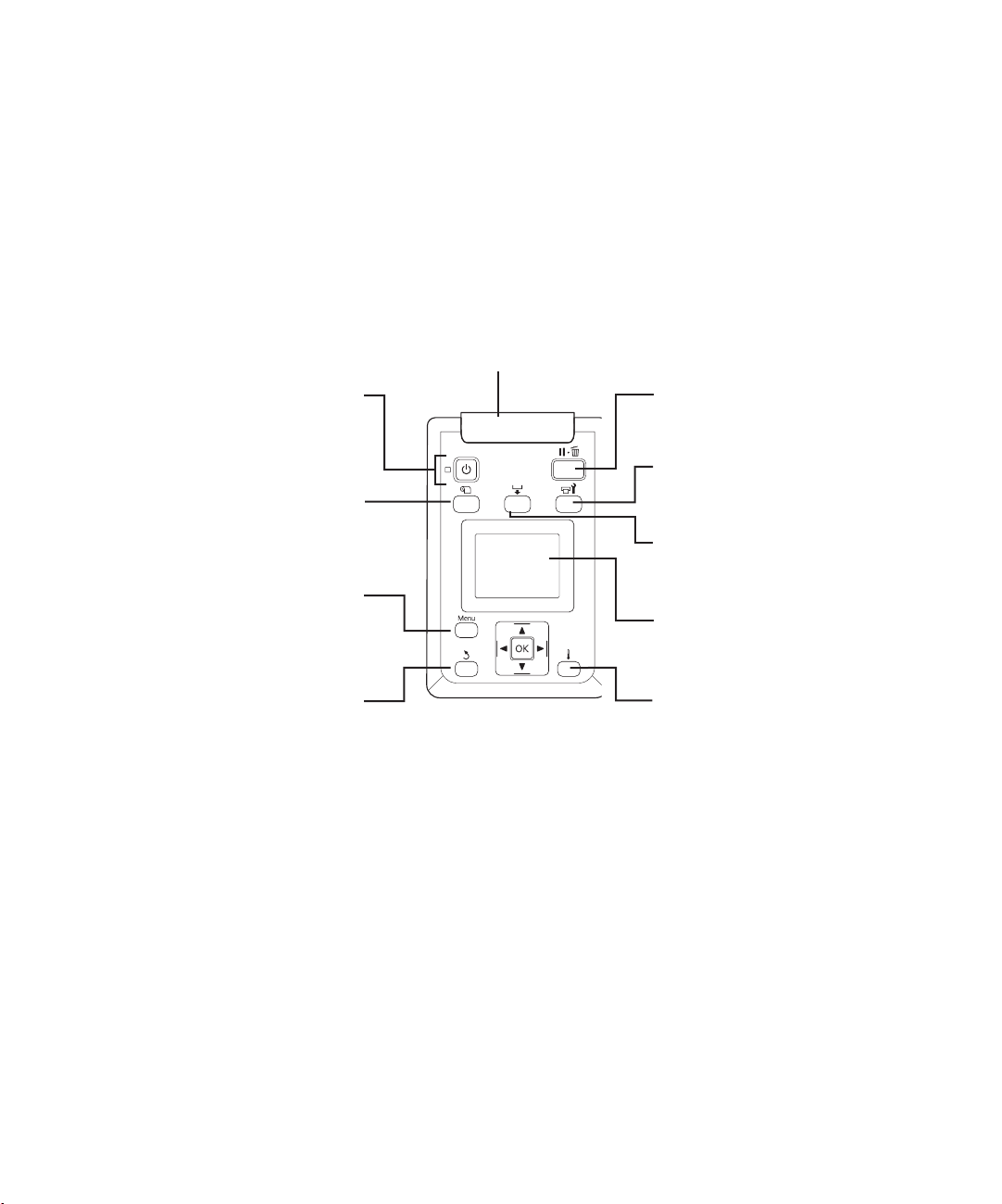
Control Panel
Panel de control
Painel de controle
Alert light
Indicador de alerta
Luz de alerta
Power button and light
Botón e indicador de encendido
Botão e luz de energia
Media setup button
Botón de configuración del papel
Botão de configuração de mídia
Menu button
Botón Menu
Botão menu
Back button
Botón de volver
Botão voltar
Pause/cancel button
Botón de pausa/cancelar
Botão Pausar/Cancelar
Maintenance button
Botón de mantenimiento
Botão de manutenção
Media feed button
Botón de alimentación del papel
Botão de alimentação de mídia
LCD display
Pantalla LCD
Visor LCD
Heating and drying button
Botón de calentamiento y secado
Botão de aquecimento e secagem
Page 3

Contents
Unpacking and Assembling the Printer ............................................................................................. 2
Assembling the Stand .................................................................................................................5
Installing the Printer ..................................................................................................................7
Installing the Take-in Reel System ........................................................................................... 11
Installing the Take-up Reel System .......................................................................................... 14
Adjusting the Media System ...........................................................................................................17
Adjusting the Take-in Reel .......................................................................................................17
Adjusting the Take-up Reel ...................................................................................................... 21
Marking the Media Loading Position .............................................................................................25
Choosing a Color Mode (S50670 and S70670 only) ......................................................................27
Installing Ink Cartridges ................................................................................................................. 27
Installing Software .......................................................................................................................... 30
Connecting to Your System ......................................................................................................30
Updating Your Printer Firmware .................................................................................................... 30
Checking the Current Firmware Version .................................................................................. 31
Updating the Firmware ............................................................................................................ 31
Configuring the Printer for Your Network ...............................................................................32
English
Page 4
2 | Unpacking and Assembling the Printer
Unpacking and Assembling the Printer
Note: Unless otherwise indicated, the illustrations in this manual show the S30670, but the instructions apply to
all three models.
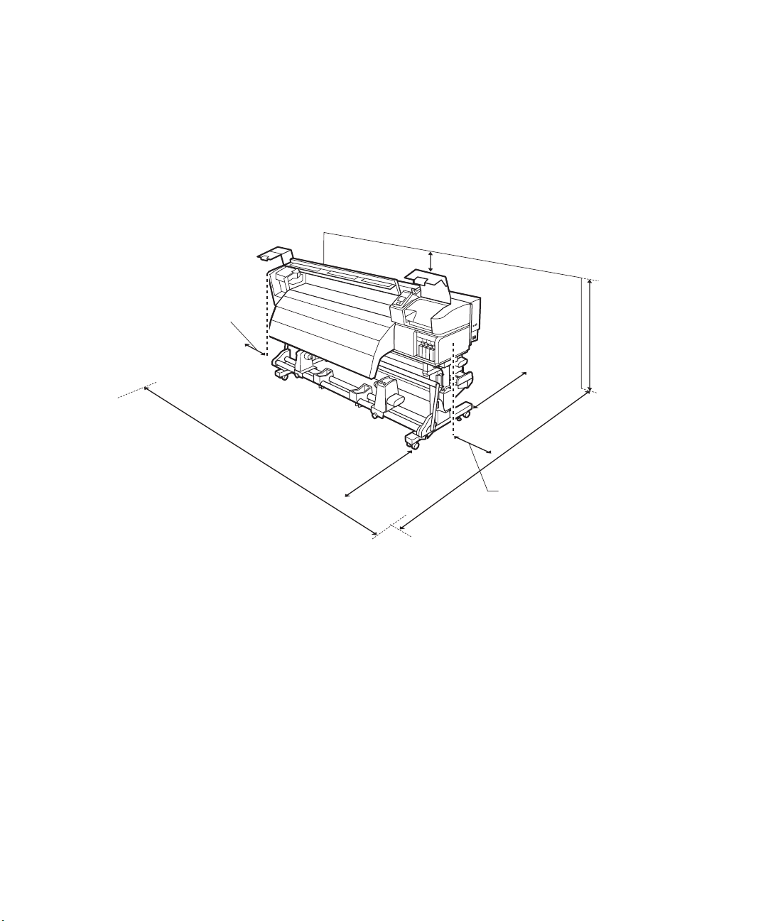
Before beginning assembly, make sure you have sufficient space to set up and use the printer. The
following illustration shows the minimum space required for using the printer:
3.9 in (100 mm)
19.7 in (500 mm)
142.5 in (3620 mm)
39.4 in (1000 mm)
39.4 in
(1000 mm)
114.3 in (2903 mm)
19.7 in (500 mm)
68.9 in
(1750 mm)
When choosing a place for the printer, leave adequate room for easy access and ventilation. Avoid locations
subject to direct sunlight, excessive heat, humidity, or dust. Be sure the printer is placed on a flat, stable
location that can support the following weight for each printer:
• S30670 - 483 lb (219 kg)
• S50670 - 524 lb (238 kg)
• S70670 - 504 lb (229 kg)
WARNING: Six people are required to unpack and install the printer.
You need an even larger floor space to assemble the printer and stand, so be sure to prepare a large, clear
area before unpacking them. Also make sure you save the box and packaging in case you need to ship the
printer later.
Page 5
Unpacking and Assembling the Printer | 3
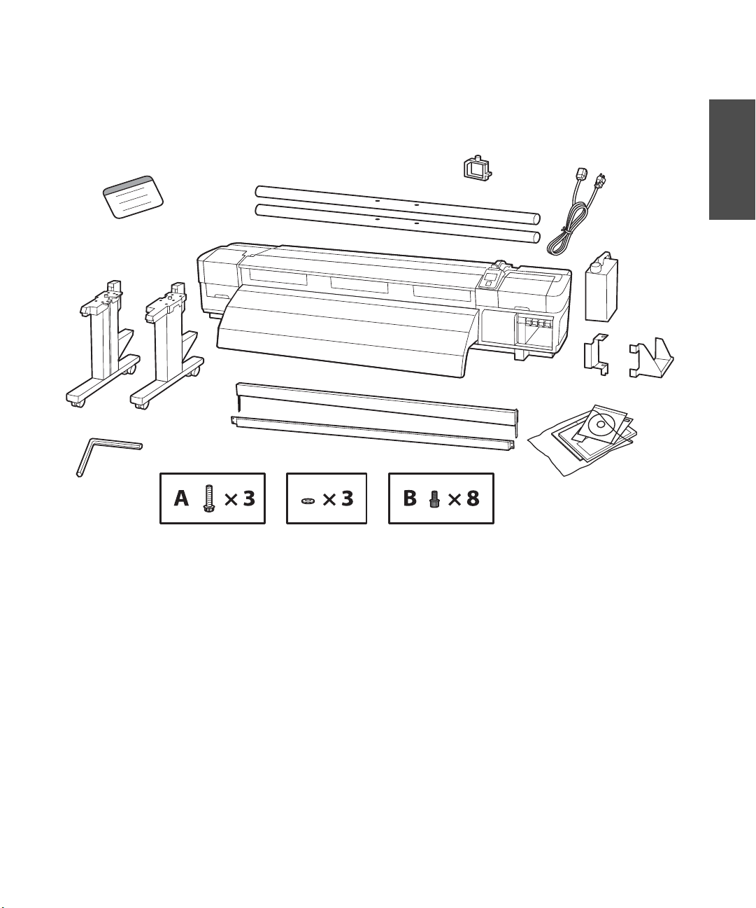
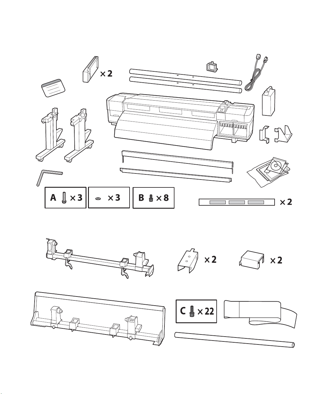
The following items should be included with your printer:
Printer and Stand Assembly (S30670):
:
English
Cable supports
Translated warning labels
Legs
Hex wrench
Carry bars
Printer
Horizontal struts
Power cable (× 2)
Waste ink
tank
Waste ink tank brackets
Software and documentation
Page 6
4 | Unpacking and Assembling the Printer
Printer and Stand Assembly (S50670 and S70670):
Replacement cartridges
Translated warning labels
Legs
Hex wrench
Media System Assembly:
Horizontal struts
Printer
Cable supports
Power cable (× 2)
Carry bars
Waste ink tank
Waste ink tank brackets
Software and documentation
Media alignment label
Take-in reel
Take-up reel
Take-in/take-up brackets
Adjustment paper
Roll core
Page 7
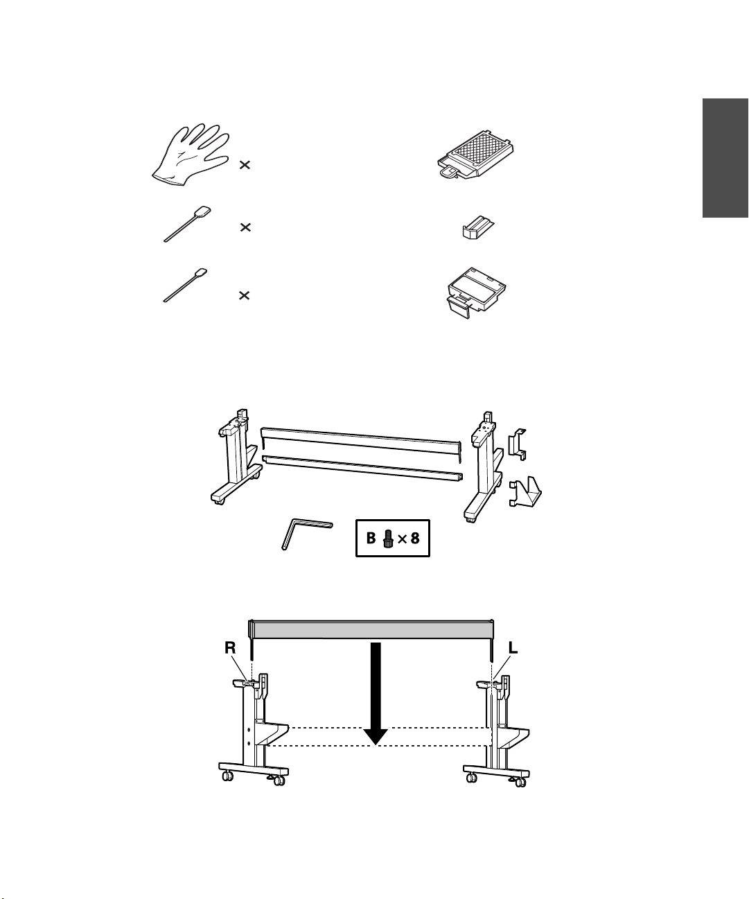
Maintenance Kit:
Assembling the Stand | 5
English
Gloves
2
Large cleaning swabs
25
Small cleaning swabs
25
Assembling the Stand
1. Unpack the stand and make sure you have all of these items.
Flushing pad
Wiper
Wiper cleaner
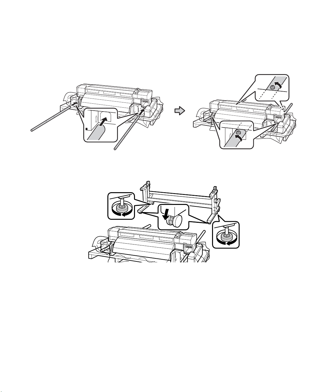
2. Slide the larger horizontal strut into both of the legs as shown.
back of stand
Page 8
6 | Assembling the Stand
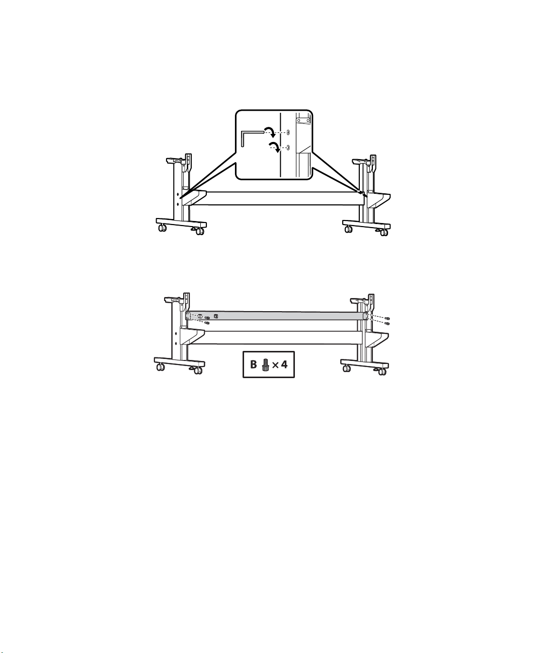
3. Use the long end of the hex wrench to tighten the pre-placed screws on each side of the horizontal
strut.
4. Attach the smaller horizontal strut by placing two B screws (four total) in the back of the right and left
legs as shown.
Page 9
Installing the Printer | 7
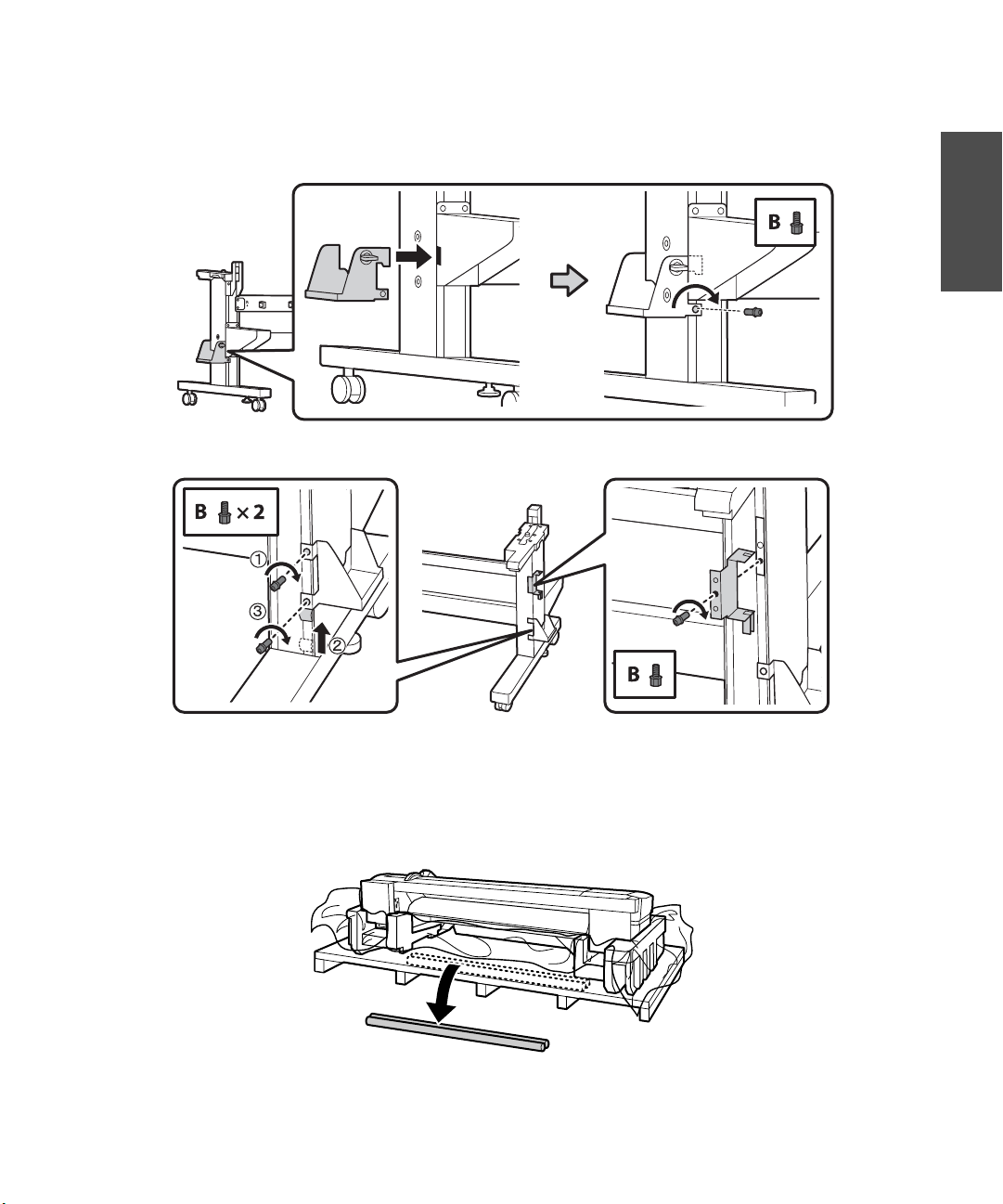
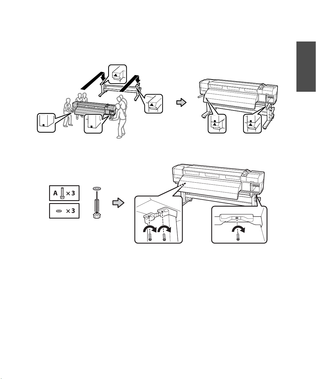
5. Attach the waste ink tank brackets as shown and secure using four B screws.
English
Installing the Printer
You need six people to install the printer; four people to carry it and two people to position it on the stand.
Use the carry bars that come with the printer to lift and move the printer.
Page 10
8 | Installing the Printer
1. From the front of the printer, insert the carry bars into both sides with the locking bolts toward the
ground as shown. Once they are inserted, rotate the bars counterclockwise 180° to lock them into
place. This keeps the printer from sliding when lifted.
Caution: Before installing the printer, make sure the stand is fixed in place. To fix the stand, rotate the feet
to the right, until they’re firmly placed on the ground and lock the casters.
Page 11
Installing the Printer | 9
2. Lift the printer onto the stand. Line up the marks on the bottom of the printer with the arrows on the
top of the stand legs before setting the printer down and removing the carry bars.
3. Attach the printer to the stand using three A screws and washers.
English
Page 12
10 | Installing the Printer
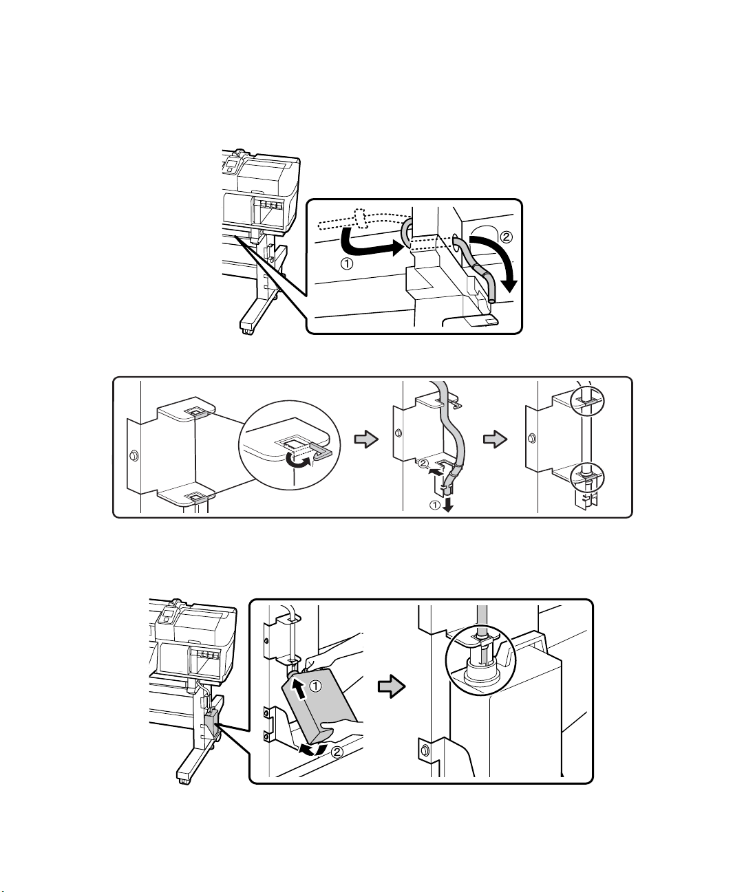
4. Feed the waste ink tube through the hole in the frame and secure in place. Make sure to pull the waste
ink tube down far enough so that the attached zip ties rest under the bottom bracket clip as shown.
5. Remove the lid from the waste ink tank and install the tank into the brackets. Make sure the waste ink
tube is inserted in the opening.
Note: Keep the lid for the waste ink tank. The tank must be sealed properly for disposal.
Page 13
Installing the Take-in Reel System | 11
Installing the Take-in Reel System
You need the following parts to assemble and attach the take-in reel system:
Caution: The take-in reel system is heavy and requires two people to install. To avoid damaging the take-in reel,
lift it by holding the two bars on the bottom as shown.
English
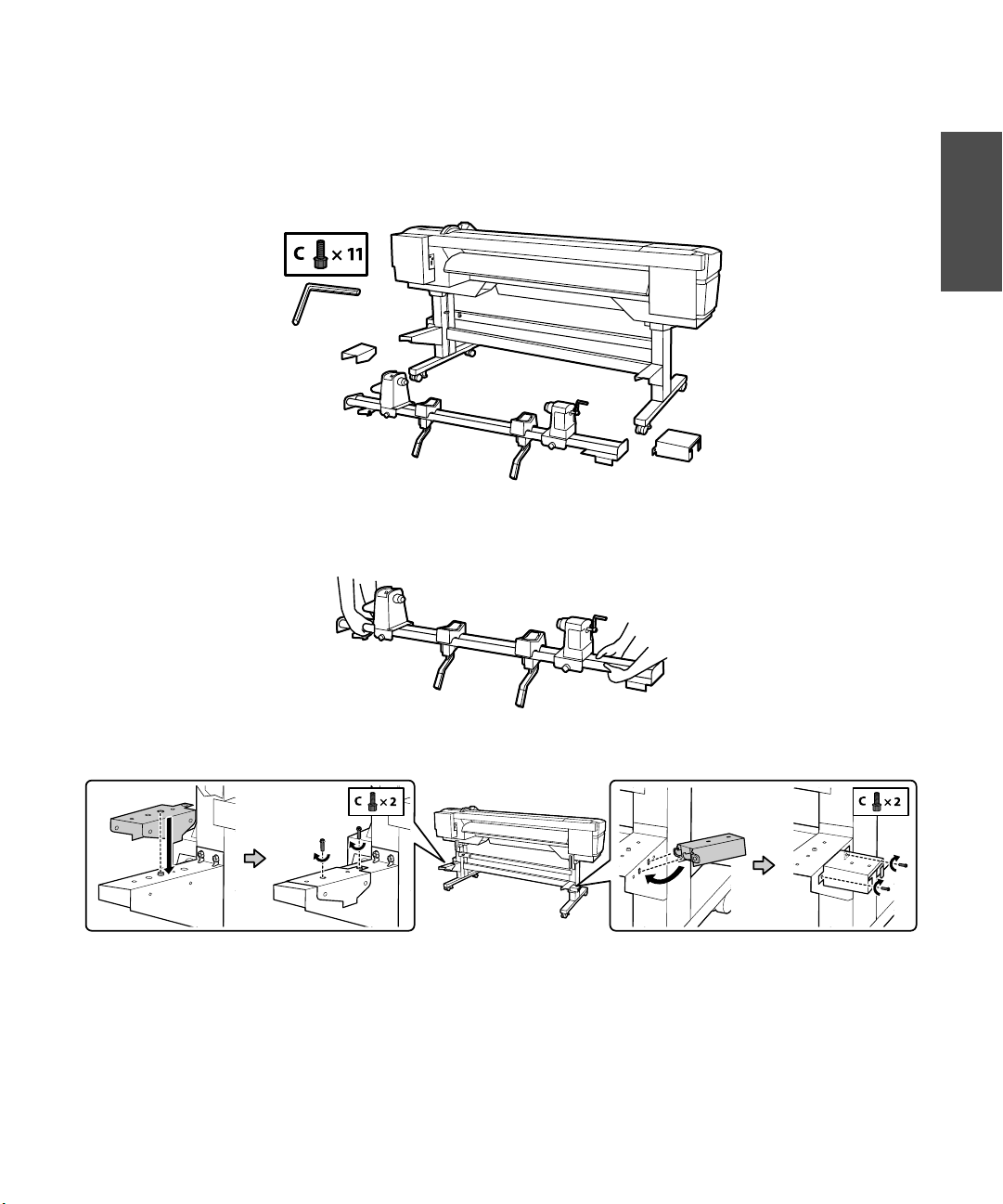
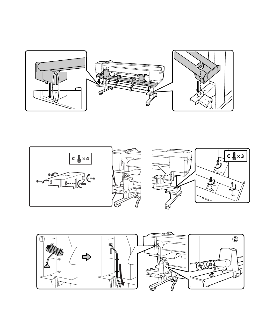
Attach the brackets to the back side of the printer with two C screws on each side as shown.
1.
Page 14
12 | Installing the Take-in Reel System
2. Lower the take-in reel onto the brackets you just installed and use size C screws to hold it in place.
Note: Only temporarily tighten the screws in the brackets on the left side until you’ve finished adjusting the
media system as described on page 17.
3. Run the communication cable that is attached to the printer through the cable supports as shown.
Page 15
Installing the Take-in Reel System | 13
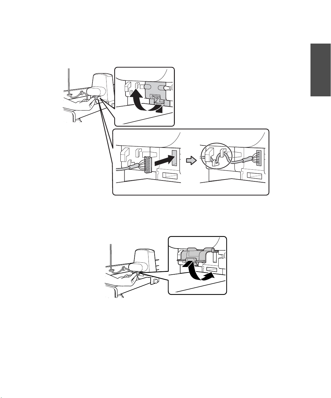
4. Lift the port cover as shown and connect the communication cable. Be sure to run the cable through
the cable supports after connecting it.
English
Note: Remove the roll core and move the left roll holder to the right to make accessing the port cover easier.
5.
Make sure the cable is fully seated in the port and close the port cover when finished.
Page 16
14 | Installing the Take-up Reel System
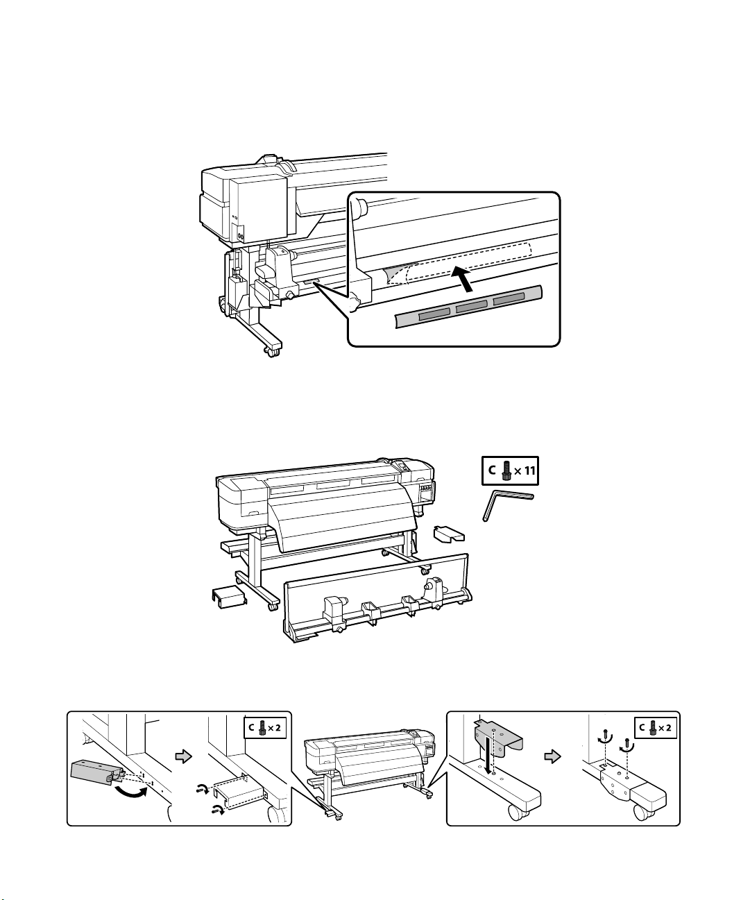
6. For the S50670/S70670, attach the media alignment label to the front bar, aligning the left end with
the left end of the guide label on the bar.
Installing the Take-up Reel System
You need the following parts to assemble and attach the take-up reel system:
1. Attach the brackets to the front of the printer as shown.
Page 17
Installing the Take-up Reel System | 15
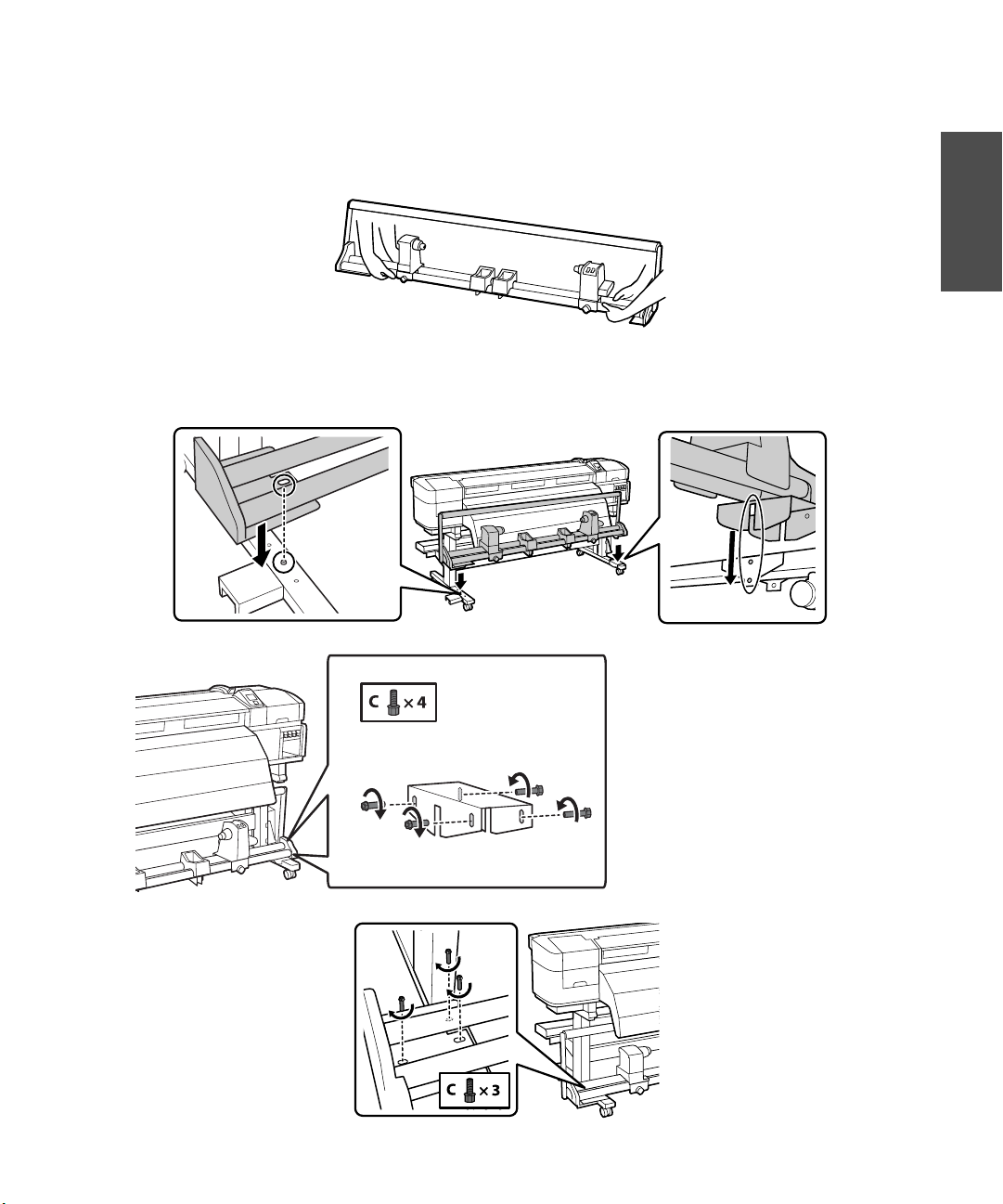
Note: The take-up reel system is heavy (47.4 lb/ 21.5 kg), so you need two people to carry it. To avoid
damaging the take-up reel, lift it by holding the two bars on the bottom as shown.
2. Lower the take-up reel system onto the brackets you just installed and use size C screws to temporarily
hold it in place.
English
Note: Only temporarily tighten the
screws in the bracket on the right side
until you’ve finished adjusting the media
system as described on page 17.
Page 18
16 | Installing the Take-up Reel System
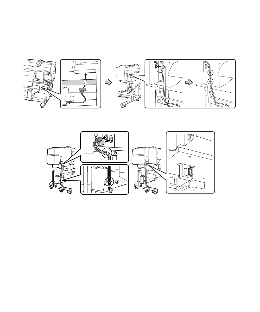
3. Connect the communication cord that is attached to the take-up reel system by running it through the
horizontal struts to the back of the printer. Place the cable in the cable supports and plug it in, making
sure to tighten the screws on the plug to secure it in place.
4. Connect the power cords to the printer and use the cable supports to restrain the cords as shown.
5. Plug the printer into outlets that are easily accessible. Note that two outlets are required, for a total of
20 amps. It is recommended that the outlets be powered by a dedicated 30-amp circuit.
Page 19
Adjusting the Media System | 17
Adjusting the Media System
After completing printer assembly, use the included roll core and adjustment paper to perform parallel
adjustment of the take-in and take-up reel. This ensures that the media will be fed straight and helps
reduce printing errors. The operation requires two people to perform any necessary adjustments in tandem
from the front and the back of the printer. Make sure the printer is leveled and on a level surface.
Adjusting the Take-in Reel
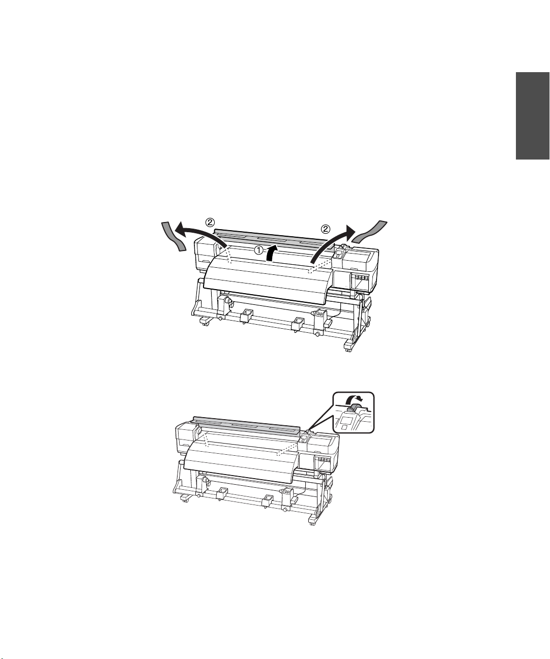
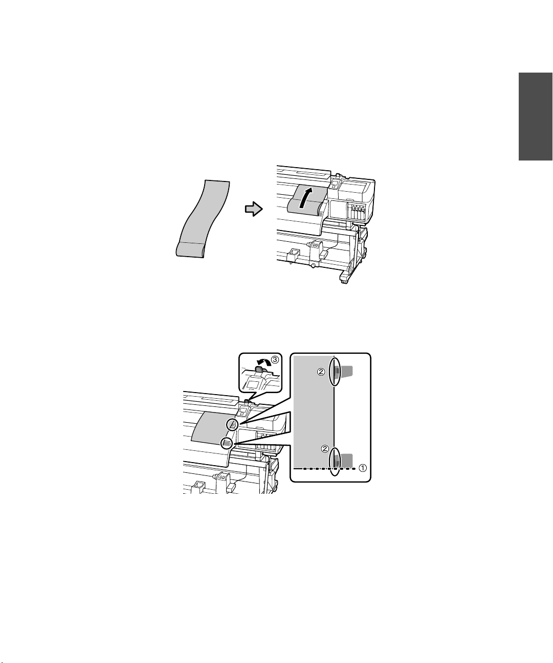
1. Open the front cover of the printer and remove the tape from the inside.
English
2. Push the media loading lever back as shown.
Page 20
18 | Adjusting the Take-in Reel
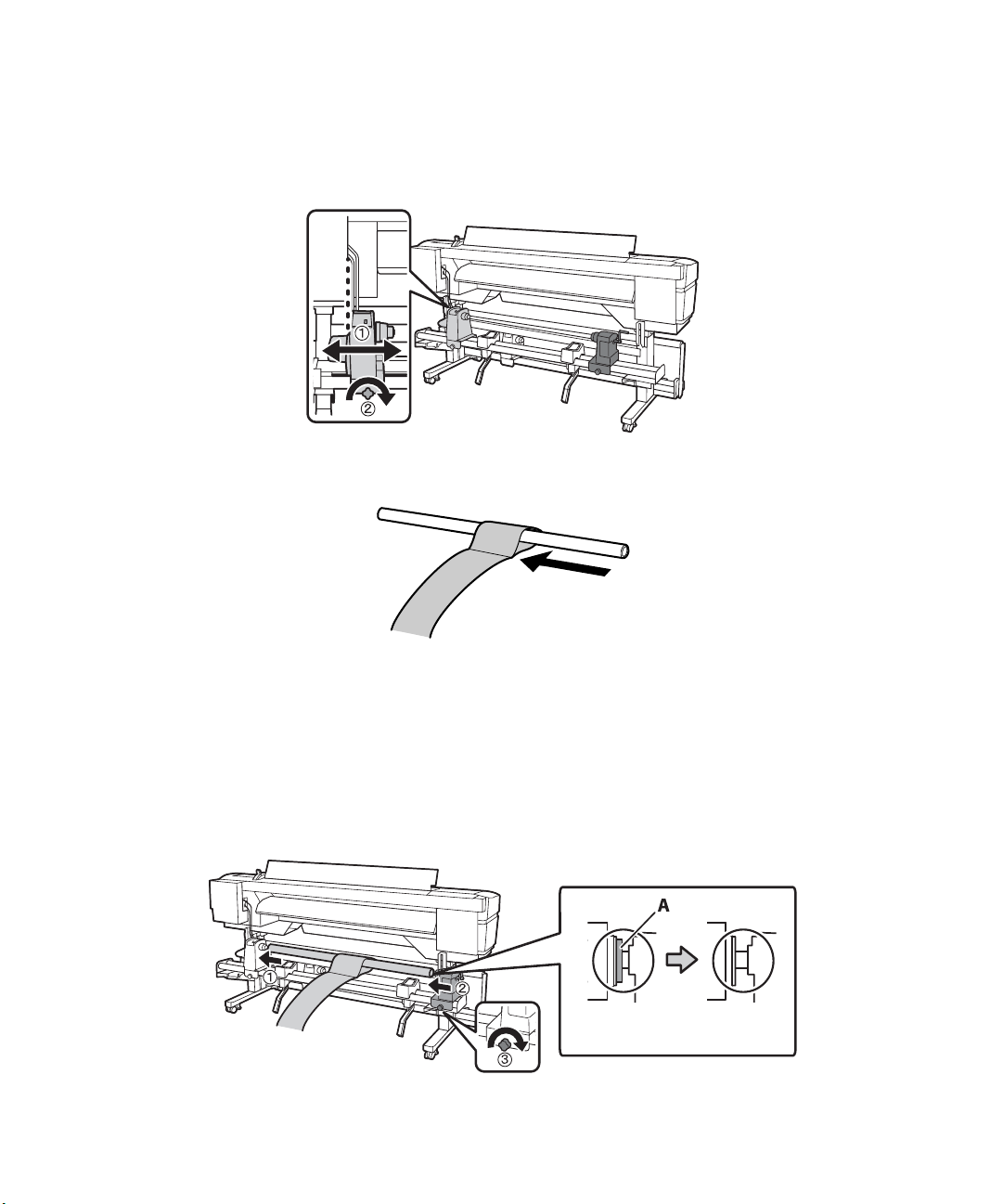
3. Align the left side of the roll holder with the left side of the opening of the printer as shown, then
tighten the roll holder fixing screw to secure it in place.
4. Slide the included roll core into the loop at the end of the adjustment paper.
5. Load the roll core with the adjustment paper into the roll holder:
• Place the core on the left roll holder.
• Move the right roll holder over to hold the roll core in place, then turn the roll holder screw on
the right to lock it into place.
• Turn the crank until part A is hidden as shown below.
Page 21
Adjusting the Take-in Reel | 19
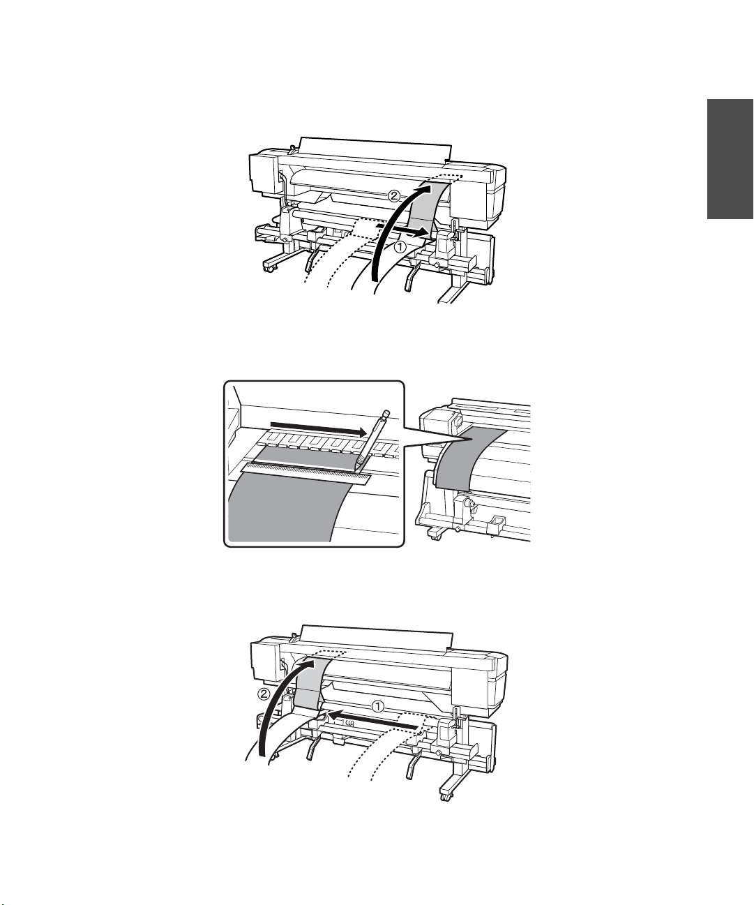
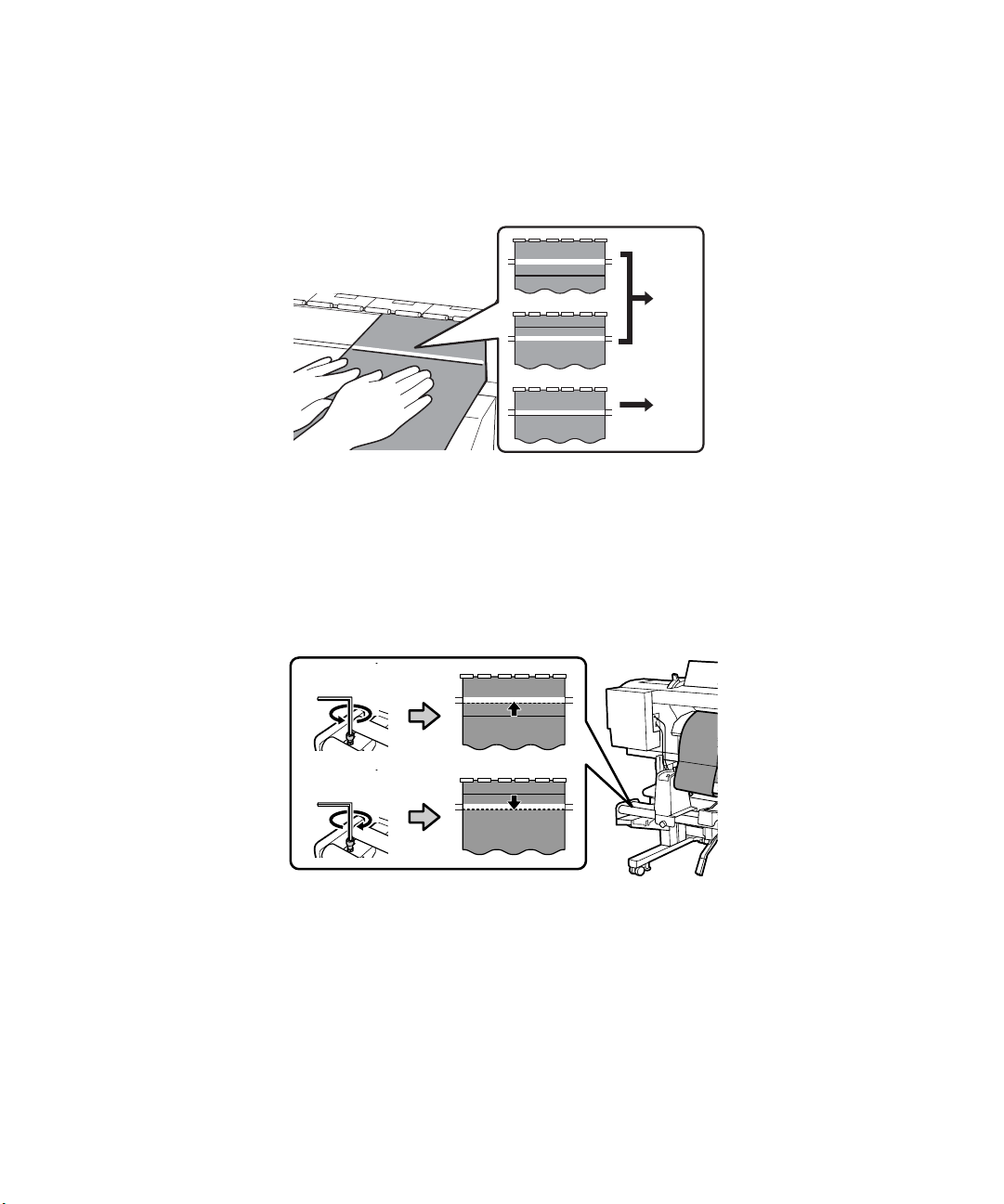
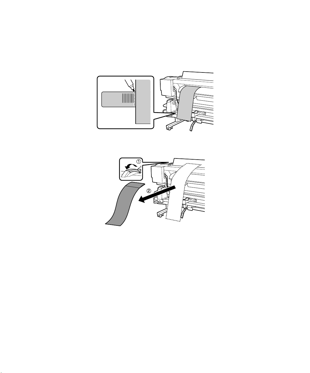
6. Slide the adjustment paper to the right side of the roll core and feed it into the printer.
7. From the front of the printer, pull the adjustment paper taut over the platen, align a ruler with the side
closest to you (front) of the white line and mark the adjustment paper with a pen.
English
8. From the back of the printer, pull out the adjustment paper, move it to the left end of the roll core and
insert it into the printer. Be sure to pull it taut with the same amount of force as before.
Page 22
20 | Adjusting the Take-in Reel
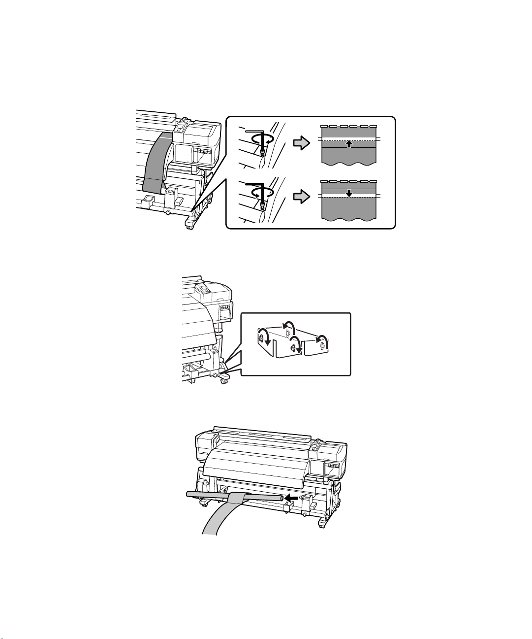
9. From the front of the printer, pull the adjustment paper taut over the platen, and check the position of
the line you drew in step 7. If the line you drew is not aligned with the white line, go to step 10. If the
lines are aligned, go to step 11.
10
11
10. From the front of the printer, have one person compare the line you drew in step 7 to the white line
on the platen. To make adjustments, have another person at the back of the printer turn the silver
adjustment screw. Turn the screw counterclockwise to move the drawn line back, and turn it
clockwise to move the drawn line forward. The line will move approximately 1 mm with each turn of
the screw. Continue to turn the silver adjustment screw until the drawn line reaches the front of the
white line as shown.
Page 23
Adjusting the Take-up Reel | 21
11. Fully tighten all four of the screws on the left bracket to secure it in place.
12. Remove the roll core and adjustment paper.
Adjusting the Take-up Reel
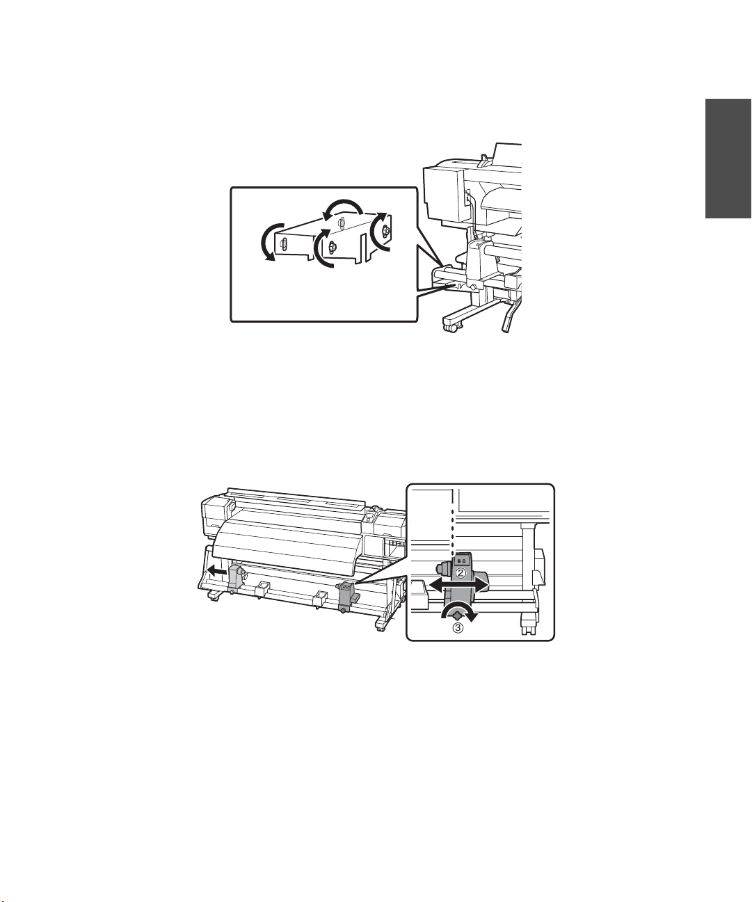
1. Align the inside edge of the right roll holder with the outside edge of the after heater as shown, then
tighten the roll holder fixing screw to secure it in place.
English
Page 24
22 | Adjusting the Take-up Reel
2. Load the roll core with the adjustment paper into the roll holder:
• Place the core on the right roll holder.
• Move the left roll holder over to hold the roll core in place.
• Press the roll holder until part A is hidden as shown below, then turn the roll holder screw on the
left to lock it into place.
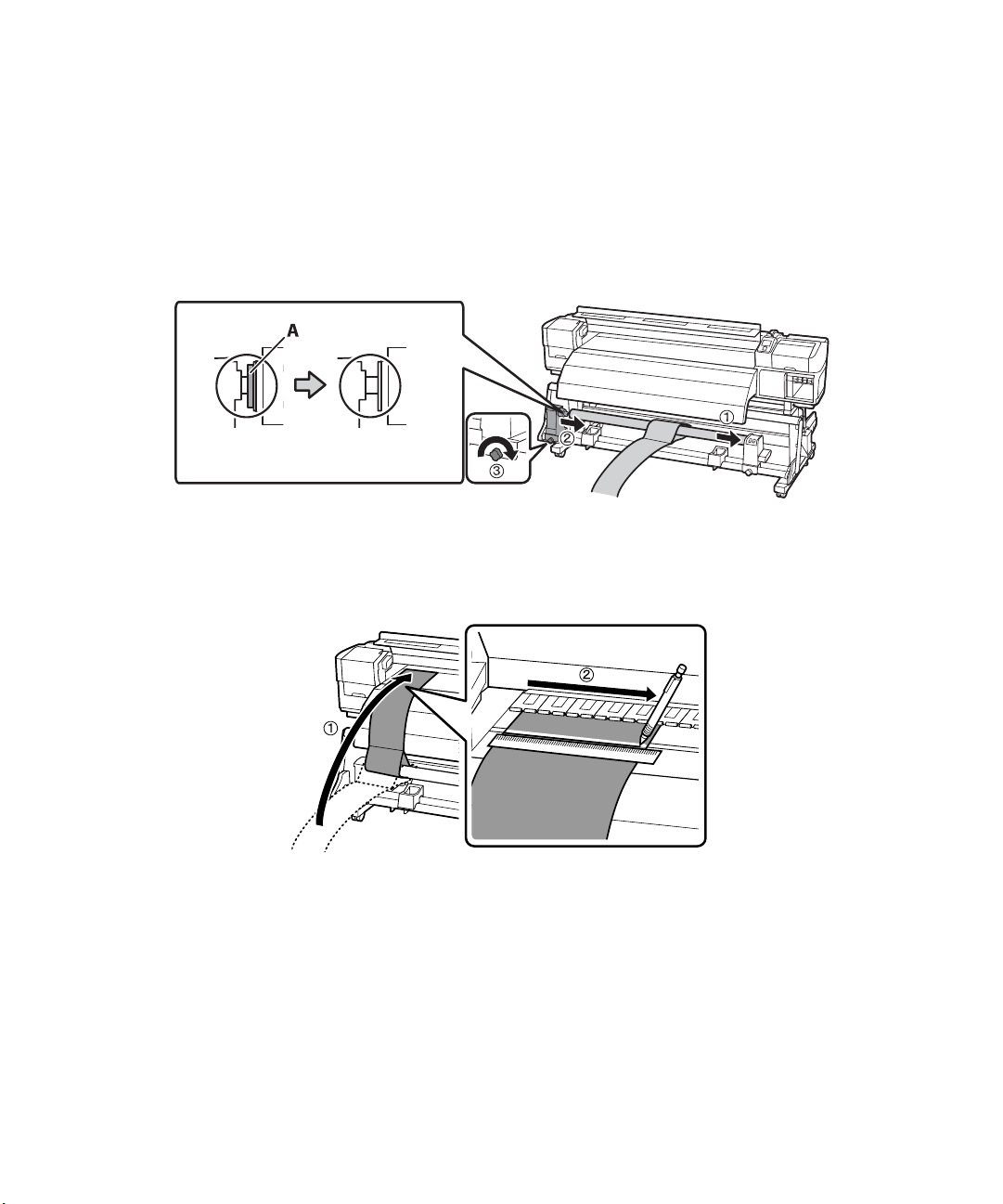
3. Slide the adjustment paper to the left side of the roll core and feed it into the printer. Pull the
adjustment paper taut over the platen, align a ruler with the front side (closest to you) of the white line
and mark the adjustment paper with a pen.
Page 25
Adjusting the Take-up Reel | 23
4. Pull out the adjustment paper, move it to the left end of the roll core and insert it into the printer. Be
sure to pull it taut with the same amount of force as before.
5. Check the positions of the white line on the platen and the line you drew in step 3 while the
adjustment paper is taut. If the line you drew is not aligned with the white line as shown, go to step 6.
If the lines are aligned, go to step 7.
English
6. From the front of the printer, have one person compare the line you drew in step 3 to the white line
on the platen. To make adjustments, have another person at the back of the printer turn the
adjustment screw. Turn the screw clockwise to move the drawn line back, and turn it
counterclockwise to move the drawn line forward. The line will move approximately 1 mm with each
turn of the screw.
Page 26
24 | Adjusting the Take-up Reel
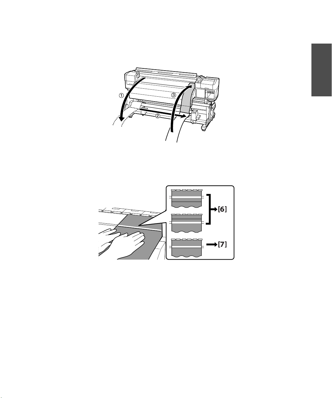
Continue to turn the adjustment screw until the drawn line reaches the front of the white line as
shown.
7. Fully tighten all four of the screws on the right bracket to secure it in place.
8. Loosen the roll holder screw and remove the roll core with the adjustment paper when finished.
Page 27
Marking the Media Loading Position | 25
Marking the Media Loading Position
Before loading the media, you need to mark the loading position on the printer using the procedure below.
This procedure helps ensure that your media feeds into the printer straight.
1. Insert the adjustment paper into the front of the printer as shown.
2. Align the bottom of the adjustment paper with the bottom of the lower label on the after heater. Make
sure the right side of the adjustment paper is aligned with the longest scale marks on both of the labels
as shown. After aligning the adjustment paper, lower the media loading lever.
English
Page 28
26 | Marking the Media Loading Position
3. From the back of the printer, pull the adjustment paper straight down until it is past the bottom of the
label on the front bar of the take-up reel. Then use an oil-based pen to mark the left side of the
adjustment paper on the label.
4. Raise the media loading lever and remove the adjustment paper from the printer.
Page 29

Choosing a Color Mode (S50670 and S70670 only) | 27
Choosing a Color Mode (S50670 and S70670 only)
Turn the printer on and configure the initial settings such as language and date using the control panel (for
more information, see your User’s Guide). Before loading the ink cartridges, you must first choose a color
mode. By selecting a mode with more colors, you can install white ink cartridges (S50670) or both white
and metallic silver ink cartridges (S70670). You can choose from the following color modes:
• 4-color or 5-color (S50670)
• 8-color or 10-color (S70670)
Caution: The color mode cannot be changed once a selection has been made.
No matter which color mode you choose, note that you must purchase an ink starter pack that contains 10
cleaning cartridges as well as the ink cartridges for your configuration.
Installing Ink Cartridges
Before loading the ink cartridges, you will first need to wash the print head.
Note: If you selected the 4-color (S50670) or 8-color (S70670) Color Mode, you need to use the Replacement
Cartridges to fill in the empty cartridge slots.These cartridges do not have ink in them and will not need to be
replaced with the other ink cartridges.
English
1.
Unpack the cleaning cartridges and, when prompted, install each one by sliding the cartridge into the
slot and pushing the lever down to lock it in place, as shown on page 28.
Note: You do not need to shake the cleaning cartridges.
2.
Follow the instructions on the control panel to charge and discharge the cleaning liquid.
3. Remove the cleaning cartridges by lifting the lever and sliding the cartridge out.
Page 30
28 | Installing Ink Cartridges
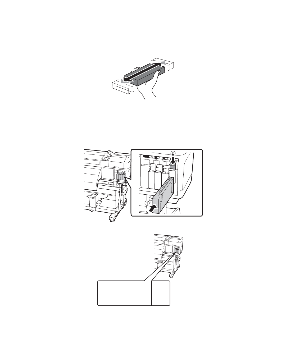
4. Unpack the ink cartridges and shake each 15 times (about 5 seconds). If you are using the white,
metallic silver, or orange cartridges, shake them 50 times (about 15 seconds).
Note: Do not touch the IC chip on the cartridge.
5.
Insert the ink cartridges as shown below and follow the instructions on the control panel to complete
ink charging.
S30670:
B
(Black)
Y
(Yellow)
M
(Magenta)
C
(Cyan)
Page 31

S50670 or S70670:
Installing Ink Cartridges | 29
English
S50670
S70670
WH
(White)
MS
(Metallic
Silver)
BK
(Black)
LK/GY
(Light Black)
Y
(Yellow)
BK
(Black)
M
(Magenta)
C
(Cyan)
C
(Cyan)
M
(Magenta)
S50670
S70670
WH
(White)
Y
(Yellow)
BK
BK
(Black)
(Black)
O
(Orange)
Y
(Yellow)
LC
(Light Cyan)
M
(Magenta)
LM
(Light
Magenta)
C
(Cyan)
WH
(White)
Caution: Do not turn off the printer or open any covers when it is charging or you may waste ink. When the ink
charging is completed, Load Media will be displayed on the control panel.
Page 32

30 | Installing Software
Installing Software
Insert the software CD that came with your printer into your computer and follow the on-screen
instructions.
Connecting to Your System
You can use USB and/or Ethernet® network connections.
For USB connection, make sure your system has the appropriate port and that you have a standard,
shielded cable, 10 feet (3 m) long or less.
Note: Do not connect the printer until a software installation screen prompts you to.
To connect to a network hub, or directly to your computer’s network interface, you need a standard RJ-45
CAT-6 network cable.
1. Plug the interface cable into the appropriate port on the printer.
2. Plug the other end of the cable into the appropriate port on your computer or network switch or hub.
3. Route the interface cable through the cable support on the printer stand along with the power cords, as
shown on page 16.
Updating Your Printer Firmware
To keep your printer features and functionality up to date, you should check for a new version of firmware
on the Epson support site and update your printer, if necessary.
Page 33

Checking the Current Firmware Version | 31
Checking the Current Firmware Version
1. Press the Menu button.
2. Press the d button until Printer Status is highlighted, then press OK.
3. Press the d button again until Firmware Version is displayed, then press OK. Note the firmware
version displayed. When finished, press the
y back button.
Updating the Firmware
Before updating your printer’s firmware, make sure your printer is turned on and connected to your
computer or network.
1. Click the EPSON LFP Remote Panel 2 icon on your desktop. You see the EPSON LFP Remote
Panel 2. Make sure your printer is selected from the drop-down menu.
2. Click the Firmware Updater button. You see the Firmware Updater window.
3. Click Acquire Latest Information to automatically download the latest firmware version for your
printer from the internet. If there is a firmware update, the message “Found the latest firmware
information. Do you want to download the firmware file?” appears. Click
Yes to download the file.
English
Note: If the Acquire Latest Information button fails to download the latest firmware, you can also find it by
visiting Epson’s support site epson.com/support (US) or epson.ca/support (Canada). You will need to
download the latest version and upload it by clicking Browse and locating the file, then continue from step 5.
4.
When the message “File download complete” appears, click OK. The file you just downloaded should
automatically be selected and appear in the File Name window.
5. Click Update and follow the on-screen instructions.
6. If the firmware version of the file is newer than what is currently installed, click Update to start the
firmware updating process.
Caution: Don’t turn off the printer while the firmware is updating.
7.
When the update is complete, close the Firmware Updater window and EPSON LFP Remote Panel 2
window.
If you connected to your printer through a network, follow the instructions in the next section to
configure the printer for your network.
Page 34

32 | Configuring the Printer for Your Network
Configuring the Printer for Your Network
Once the printer is connected to your network, follow these steps to configure it:
1. Turn on the printer.
2. Start EpsonNet Config.
The EpsonNet Config program you installed from the CD that came with your printer searches for all
EPSON printers on the network and displays the MAC address for each printer that it finds.
3. Highlight the printer you want to configure and click Configuration to access the TCP/IP selection
screen.
4. If necessary, contact your network administrator for instructions on assigning an appropriate IP
address. A static IP address is recommended.
EPSON and SureColor are registered trademarks, and EPSON Exceed Your Vision is a registered logomark of Seiko Epson
Corporation.
General Notice: Other product names used herein are for identification purposes only and may be trademarks of their respective
owners. Epson disclaims any and all rights in those marks.
This information is subject to change without notice.
Page 35

Contenido
Desembalaje y montaje de la impresora ........................................................................................... 34
Montaje del soporte ................................................................................................................. 37
Instalación de la impresora ....................................................................................................... 39
Instalación del sistema de rodillo de alimentación .................................................................... 43
Instalación del sistema de rodillo de recogida ........................................................................... 46
Ajuste del sistema de materiales ....................................................................................................... 50
Ajuste del rodillo de alimentación ............................................................................................ 50
Ajuste del rodillo de recogida .................................................................................................... 54
Marcado de la posición de carga de papel ........................................................................................ 58
Selección de un modo de color (S50670 y S70670 solamente) ........................................................ 60
Instalación de los cartuchos de tinta ................................................................................................ 60
Instalación del software ...................................................................................................................63
Conexión a su sistema .............................................................................................................. 63
Actualización del firmware de la impresora .....................................................................................64
Comprobación de la versión del firmware actual ......................................................................64
Actualización del firmware ....................................................................................................... 64
Configuración de la impresora para la red ................................................................................ 65
Marcas registradas .................................................................................................................... 66
| 33
Español
Page 36

34 | Desembalaje y montaje de la impresora
.
Desembalaje y montaje de la impresora
Nota: Las ilustraciones incluidas en el presente muestran la impresora S30670, a no ser indicado lo contrario,
pero las instrucciones aplican a los tres modelos.
En el presente, la palabra “papel” se utiliza para referirse a todos los materiales de impresión compatibles con
esta impresora.
Antes de comenzar el montaje, asegúrese de tener espacio suficiente para instalar y usar la impresora. En la
siguiente ilustración se muestra el espacio mínimo que se requiere para usar la impresora:
3,9 pulg.
(10 cm)
19,7 pulg.
(50 cm)
142,5 pulg.
(362 cm)
39,4 pulg.
(100 cm)
39,4 pulg.
(100 cm)
114,3 pulg.
(290,3 cm)
19,7 pulg.
(50 cm)
68,9 pulg
(175 cm)
Al elegir un lugar para la impresora, deje suficiente espacio adecuado para facilitar el acceso y la ventilación.
Evite lugares que estén sometidos a luz solar directa, calor excesivo, humedad o polvo. Coloque la
impresora sobre un lugar plano y estable que pueda soportar el peso de la impresora:
• S30670 - 483 lb (219 kg)
• S50670 - 524 lb (238 kg)
• S70670 - 504 lb (229 kg)
ADVERTENCIA: Se requieren seis personas para desembalar e instalar la impresora.
Se necesita un espacio de mayor tamaño aún para montar la impresora y el soporte. Prepare un área
despejada y amplia antes de desembalarlos. Además guarde la caja y el envoltorio en caso de que necesite
transportar la impresora posteriormente.
Page 37

Desembalaje y montaje de la impresora | 35
La impresora debería incluir los siguientes elementos:
Montaje de la impresora y del soporte (S30670):
:
Soporte para cables
Etiquetas de
avisos traducidas
Patas
Llave
hexagonal
Barras de transporte
Impresora
Montantes horizontales
Cable de
alimentación (× 2)
Español
Depósito
de tinta de
desecho
Soportes para el depósito
de tinta de desecho
Software y
documentación
Page 38

36 | Desembalaje y montaje de la impresora
Montaje de la impresora y del soporte (S50670 y S70670):
Cartuchos de
reemplazo
Etiquetas de
avisos traducidas
Impresora
Patas
Llave hexagonal
Montantes horizontales
Montaje del sistema de material de impresión:
Soporte para
cables
Barras de transporte
Cable de
alimentación (× 2)
Depósito
de tinta de
desecho
Soportes para el depósito
de tinta de desecho
Software y documentación
Etiqueta para alinear el papel
Rodillo de
alimentación
Rodillo de recogida
Soportes de alimentación
y de recogida
Papel de ajuste
Portarrollos
Page 39

Kit de mantenimiento:
Montaje del soporte | 37
Guantes
2
Bastoncillos grandes
25
de limpieza
Bastoncillos pequeños
25
de limpieza
Almohadilla
de aclarado
Limpiacabezales
Dispositivo de
limpieza del
limpiacabezales
Montaje del soporte
1. Desembale el soporte y asegúrese de que se hayan incluido todos los elementos que se muestran
a continuación.
Español
2. Coloque el montante horizontal más grande en ambas patas, tal como se muestra a continuación.
Parte posterior del soporte
Page 40

38 | Montaje del soporte
3. Utilice el brazo largo de la llave hexagonal para apretar los tornillos pre-instalados en cada costado del
montante horizontal.
4. Fije las el montante horizontal más pequeño a la parte posterior de las patas con cuatro tornillos B (2
para cada lado), tal como se muestra a continuación.
Page 41

Instalación de la impresora | 39
5. Instale los soportes del depósito de tinta de desecho, tal como se muestra a continuación, y fíjelos con
cuatro tornillos
B.
Español
Instalación de la impresora
Se necesitan seis personas para instalar la impresora, cuatro para transportarla y dos para colocarla en el
soporte. Utilice las barras de transporte que vienen con la impresora para levantarla y desplazarla.
Page 42

40 | Instalación de la impresora
1. Inserte las barras de transporte en ambos lados de la parte delantera de la impresora con los pernos
de sujeción orientado hacia el suelo, tal como se muestra a continuación. Después de insertarlas, gire
las barras 180° hacia la izquierda para fijarlas en su lugar. De esta forma, la impresora no se desplazará
al levantarla.
Precaución: Antes de instalar la impresora, confirme que el soporte esté fijo en su lugar. Para fijar el soporte,
gire las patas hacia la derecha hasta que estén firmemente ubicadas en el suelo y bloquee las ruedas.
Page 43

Instalación de la impresora | 41
2. Coloque la impresora sobre el soporte. Alinee las marcas que hay en la parte inferior de la impresora
con las flechas de la parte superior de las patas del soporte antes de colocar la impresora y quitar las
barras de transporte.
3. Fije la impresora al soporte con tres tornillos A y tres arandelas.
Español
Page 44

42 | Instalación de la impresora
4. Introduzca el tubo de tinta de desecho por el orificio que hay en el marco y fíjelo en su lugar. Tire el
tubo de tinta de desecho hacia abajo lo suficiente como para que las bridas sujetacables adjuntas
queden debajo de la abrazadera del soporte inferior, tal como se muestra a continuación.
5. Quite la tapa del depósito de tinta de desecho e instale el depósito en los soportes. Asegúrese de que el
tubo de tinta de desecho se inserte en la abertura.
Nota: Guarde la tapa del depósito de tinta de desecho. Selle el depósito adecuadamente antes
de descartarlo.
Page 45

Instalación del sistema de rodillo de alimentación | 43
Instalación del sistema de rodillo de alimentación
Necesitará las siguientes piezas para montar y conectar el sistema de rodillo de alimentación:
Precaución: El sistema de rodillo de alimentación es pesado, por lo que se requieren dos personas para
instalarlo. Para no dañar el rodillo de recogida, sujételo por debajo de las dos barras y levántelo, tal como se
muestra a continuación.
Español
Fije los soportes a la parte posterior de la impresora con dos tornillos C en cada lado, tal como se
1.
muestra a continuación.
Page 46

44 | Instalación del sistema de rodillo de alimentación
2. Coloque el rodillo de alimentación en los soportes que instaló y utilice tornillos tamaño C para fijarlo
en su lugar.
Nota: Apriete temporalmente los tornillos del soporte del lado izquierdo hasta que haya terminado de ajustar
el sistema de material de impresión, según se describe en la página 50.
Pase el cable de comunicación conectado a la impresora a través de los soportes para cables, tal como se
3.
muestra a continuación.
Page 47

Instalación del sistema de rodillo de alimentación | 45
4. Levante la tapa del puerto, tal como se muestra a continuación, y conecte el cable de comunicación.
Asegúrese de pasar el cable a través de los soportes para cables después de conectarlo.
Español
Nota: Quite el portarrollos y mueva el tope izquierdo del rollo hacia la derecha para facilitar el acceso a
la cubierta del puerto.
5.
Asegúrese de que el cable esté bien conectado al puerto y cierre la tapa del puerto al terminar.
Page 48

46 | Instalación del sistema de rodillo de recogida
6. Para las impresoras S50670 y S70670 solamente: Pegue la etiqueta para alinear el papel a la barra
delantera; tenga cuidado de alinear la orilla izquierda de la etiqueta con la orilla izquierda del espacio
para la etiqueta localizado en la barra.
Instalación del sistema de rodillo de recogida
Necesitará las siguientes piezas para montar y conectar el sistema de rodillo de recogida:
Page 49

Instalación del sistema de rodillo de recogida | 47
1. Fije los soportes a la parte delantera de la impresora, tal como se muestra a continuación:
Nota: El sistema de rodillo de recogida es pesado (47,4 lb; 21,5 kg), por lo que se necesitarán dos personas
para transportarlo. Para evitar dañar el rodillo de recogida, sujételo por la parte inferior de las dos barras y
levántelo, tal como se muestra a continuación.
Español
Page 50

48 | Instalación del sistema de rodillo de recogida
2. Coloque el rodillo de recogida en los soportes que instaló y utilice tornillos tamaño C para fijarlo
temporalmente en su lugar.
Nota: Apriete los tornillos del soporte
derecho, temporalmente, hasta que
haya terminado de ajustar el sistema
de material, tal como se describe en
la página 50.
Page 51

Instalación del sistema de rodillo de recogida | 49
3. Conecte el cable de comunicación adjunto al sistema de rodillo de recogida. Para esto, tiéndalo a través
de los montantes horizontales hasta la parte posterior de la impresora. Coloque el cable en los soportes
para cables y conéctelo. Asegúrese de apretar los tornillos en el enchufe para fijarlo en su lugar.
4. Conecte los cables de alimentación a la impresora y utilice los soportes para cables para sujetar los
cables, tal como se muestra a continuación.
Español
5. Conecte la impresora a tomas de corriente de fácil acceso. Tenga en cuenta que se requiren dos tomas
de corriente, para un total de 20 amperios. Se recomienda que las tomas de corriente sean
suministradas por un circuito dedicado de 30 amperios.
Page 52

50 | Ajuste del sistema de materiales
Ajuste del sistema de materiales
Después de completar el montaje de la impresora, utilice el portarrollos y el papel de ajuste que se incluyen
con la impresora para realizar ajustes paralelos del rodillo de alimentación y de recogida. Esto garantiza que
el material avance por un recorrido recto y ayuda a reducir los errores de impresión. Esta operación
requiere que dos personas realicen todos los ajustes necesarios conjuntamente desde la parte delantera y
posterior de la impresora. La impresora debe estar nivelada y en una superficie pareja.
Ajuste del rodillo de alimentación
1. Abra la tapa frontal de la impresora y retire la cinta del interior.
2. Empuje la palanca de carga del papel, tal como se muestra a continuación.
Page 53

Ajuste del rodillo de alimentación | 51
3. Alinee el lado izquierdo del tope del rollo con el lado izquierdo de la abertura de la impresora, tal como
se muestra a continuación, luego, apriete el seguro del tope del rollo para fijarlo en su lugar.
4. Deslice el portarrollos incluido con la impresora en el acoplamiento del extremo del papel de ajuste.
Español
5. Cargue el portarrollos con el papel de ajuste en el tope del rollo:
• Coloque el eje en el lado izquierdo del tope del rollo.
• Desplace el tope derecho del rollo de modo que el portarrollos quede fijo y luego gire el seguro del
tope del rollo hacia la derecha para bloquearlo en su lugar.
• Gire la manivela hasta que la pieza A quede oculta, tal como se muestra a continuación.
Page 54

52 | Ajuste del rodillo de alimentación
6. Deslice el papel de ajuste hacia el lado derecho del portarrollos e introdúzcalo en la impresora.
7. Desde la parte delantera de la impresora, tense el papel de ajuste sobre el cabezal, alinee una regla con
el lado más cercano a usted (delante) de la línea blanca y marque el papel de ajuste con un bolígrafo.
8. Desde la parte posterior de la impresora, saque el papel de ajuste, muévalo al extremo izquierdo del
portarrollos e introdúzcalo en la impresora. Asegúrese de tensarlo con la misma fuerza que antes.
Page 55

Ajuste del rodillo de alimentación | 53
9. Desde la parte delantera de la impresora, tense el papel de ajuste sobre el cabezal y revise la posición de
la línea que dibujó en el paso 7. Si la línea que dibujó no está alineada con la línea blanca, como se
muestra a continuación, siga con el paso 10. Si las líneas están alineadas, vaya al paso 11.
10
11
10. Desde la parte delantera de la impresora, pídale a una persona que compare la línea que usted dibujó
en el paso 7 con la línea blanca del cabezal. Para realizar ajustes, pídale a otra persona que desde la
parte posterior de la impresora gire el tornillo de ajuste (de color plateado). Gire el tornillo hacia la
izquierda para mover la línea dibujada hacia atrás y gírelo hacia la derecha para mover la línea hacia
adelante. La línea se moverá aproximadamente 1 mm con cada giro del tornillo. Continúe girando
el tornillo de ajuste plateado hasta que la línea dibujada llegue frente a la línea blanca, tal como se
muestra a continuación.
Español
Page 56

54 | Ajuste del rodillo de recogida
11. Apriete completamente los cuatro tornillos del soporte izquierdo para fijarlo en su lugar.
12. Retire el portarrollos y el papel de ajuste.
Ajuste del rodillo de recogida
1. Alinee el borde interior del tope derecho del rollo con el borde exterior del post-calentador, tal como se
muestra a continuación, luego apriete el seguro del tope del rollo para fijarlo en su lugar.
Page 57

Ajuste del rodillo de recogida | 55
2. Cargue el portarrollos con el papel de ajuste en el tope del rollo:
• Coloque el eje en el lado derecho del tope del rollo.
• Desplace el tope izquierdo del rollo para sostener el portarrollos en su lugar.
• Presione el tope del rollo hasta que la pieza A quede oculta, tal como se muestra a continuación,
luego apriete el seguro del tope del rollo en el lado izquierdo para fijarlo en su lugar.
3. Deslice el papel de ajuste hacia el lado izquierdo del portarrollos e introdúzcalo en la impresora. Tense
el papel de ajuste sobre el cabezal, alinee una regla con la parte delantera (el más cercano a usted) de la
línea blanca y marque el papel de ajuste con un lápiz.
Español
4. Saque el papel de ajuste, muévalo hacia el extremo izquierdo del portarrollos e introdúzcalo en la
impresora. Asegúrese de tensarlo con la misma fuerza que antes.
Page 58

56 | Ajuste del rodillo de recogida
5. Compruebe las posiciones de la línea blanca en el cabezal y de la línea que dibujó en el paso 3 mientras
el papel de ajuste está tensado. Si la línea que dibujó no está alineada con la línea blanca, tal como se
muestra a continuación, siga con el paso 6. Si las líneas están alineadas, vaya al paso 7.
6. Desde la parte delantera de la impresora, pídale a una persona que compare la línea que usted dibujó
en el paso 3 con la línea blanca del cabezal. Para realizar ajustes, pídale a otra persona en la parte
posterior de la impresora que gire el tornillo de ajuste. Gire el tornillo hacia la derecha para mover la
línea dibujada hacia atrás y gírelo hacia la izquierda para mover la línea hacia adelante. La línea se
moverá aproximadamente 1 mm con cada giro del tornillo.
Siga girando el tornillo de ajuste hasta que la línea dibujada llegue delante de la línea blanca, tal como
se muestra a continuación.
Page 59

Ajuste del rodillo de recogida | 57
7. Apriete completamente los cuatro seguros del soporte derecho para fijarlo en su lugar.
8. Afloje el seguro del tope del rollo y retire el tope del portarrollos con el papel de ajuste cuando termine.
Español
Page 60

58 | Marcado de la posición de carga de papel
Marcado de la posición de carga de papel
Antes de cargar el papel, debe marcar la posición de carga en la impresora con el procedimiento anterior.
Este procedimiento ayuda a garantizar que el papel avance en la impresora de manera recta.
1. Inserte el papel de ajuste en la parte delantera de la impresora, tal como se muestra a continuación.
2. Alinee la parte inferior del papel de ajuste con la parte inferior de la etiqueta inferior del
post-calentador. Asegúrese de que el lado derecho del papel de ajuste esté alineado con las marcas de
escala más largas en ambas etiquetas, como se muestra a continuación. Después de alinear el papel de
ajuste, baje la palanca de carga del papel.
Page 61

Marcado de la posición de carga de papel | 59
3. Desde la parte posterior de la impresora, tire del papel de ajuste hacia abajo hasta que pase la parte
posterior de la etiqueta en la barra delantera del rodillo de recogida. Luego, use un bolígrafo a base de
aceite para marcar el lado izquierdo del papel de ajuste en la etiqueta.
4. Suba la palanca de carga del papel y retire el papel de ajuste de la impresora.
Español
Page 62

60 | Selección de un modo de color (S50670 y S70670 solamente)
Selección de un modo de color (S50670 y S70670 solamente)
Encienda la impresora y configure los ajustes iniciales, tales como el idioma y la fecha, utilizando el panel
de control (para obtener más información, consulte el Manual del usuario). Antes de instalar los cartuchos
de tinta, debe seleccionar un modo de color. Si selecciona un modo con más colores, puede instalar
cartuchos de tinta blanca (S50670) o cartuchos de tinta blanca y plateada metálica (S70670). Puede elegir
uno de los siguientes modos de color:
• 4 colores o 5 colores (S50670)
• 8 colores o 10 colores (S70670)
Precaución: Una vez que haya seleccionado un modo de color, no podrá modificarlo.
Tenga en cuenta que independientemente de cuál modo de color seleccionó, debe comprar un set de
cartuchos iniciales que consiste de 10 cartuchos de limpieza al igual que los cartuchos de tinta requeridos
para su configuración.
Instalación de los cartuchos de tinta
Antes de cargar los cartuchos de tinta, deberá primero lavar el cabezal de impresión.
Nota: Si seleccionó el modo de cuatro colores (S50670) o de ocho colores (S70670), tendrá que utilizar los
cartuchos de reemplazo para llenar las ranuras vacías del compartimento de cartuchos. Estos cartuchos no tienen
tinta y no tendrá que reemplazarlos como los cartuchos normales.
1. Desembale los cartuchos de limpieza y, cuando la impresora se lo indique, instale cada uno en la
ranura correspondiente y presione la palanca hacia abajo para fijarlos en su lugar, tal como se indica
en la página 61.
Nota: No es necesario agitar los cartuchos de limpieza.
2.
Siga las instrucciones del panel de control para cargar y descargar el líquido de limpieza.
3. Para retirar los cartuchos de limpieza, levante la palanca y deslice el cartucho hacia afuera.
Page 63

Instalación de los cartuchos de tinta | 61
4. Desembale los cartuchos de tinta y agite cada uno 15 veces (aproximadamente 5 segundos). Si va
a instalar un cartucho de tinta blanca, de tinta plateada metálica, o de tinta naranja, agítelo unas
50 veces (unos 15 segundos).
Nota: No toque el chip CI del cartucho.
5.
Introduzca cada cartucho como se muestra a continuación y siga las instrucciones que aparecen en la
pantalla LCD del panel de control para completar la carga de la tinta.
S30670:
Español
Page 64

62 | Instalación de los cartuchos de tinta
S50670 o S70670:
S50670
S70670
Precaución: No apague la impresora o abra ninguna de las cubiertas mientras la tinta se esté cargando o, de lo
contrario, podría gastar tinta. Cuando la carga de tinta haya finalizado, aparecerá un mensaje en el panel de control
indicándole que cargue papel.
Page 65

Instalación del software | 63
Instalación del software
Introduzca en la computadora el CD del software incluido con la impresora y siga las instrucciones
en pantalla.
Conexión a su sistema
Puede usar conexiones USB o de red Ethernet®.
Para una conexión USB, asegúrese de que su sistema tenga el puerto correcto y cuente con un cable
blindado estándar de 3 m (10 pies) de longitud o menos.
Nota: No conecte la impresora hasta que la pantalla de instalación del software se lo indique.
Para conectar la impresora a un concentrador de red, o directamente a la interface de red de su
computadora, necesita un cable de red estándar de CAT-6 con conectores RJ-45.
1. Conecte el cable de interface en el puerto de la impresora correcto.
2. Conecte el otro extremo del cable al puerto correcto de su computadora o del conmutador o
concentrador de red.
Español
3. Dirija el cable de interface por el soporte para cables del soporte de la impresora junto con los cables de
alimentación, tal como se muestra en la página 49.
Page 66

64 | Actualización del firmware de la impresora
Actualización del firmware de la impresora
Para mantener las funciones y la funcionalidad de la impresora actualizadas, debe revisar si existe una
versión más reciente del firmware en la página de soporte técnico de Epson y actualizar la impresora, si es
necesario.
Comprobación de la versión del firmware actual
1. Pulse el botón Menu.
2. Pulse el botón d hasta que se resalte Estado De Impresora y luego pulse el botón OK.
3. Pulse el botón d otra vez hasta que se resalte Versión Firmware y luego pulse el botón OK. Anote la
versión del firmware que aparece en la pantalla LCD. Cuando haya terminado, pulse el botón
Actualización del firmware
Antes de actualizar el firmware de la impresora, compruebe que la impresora esté encendida y conectada a
su computadora o red.
y.
1. Haga clic en el ícono EPSON LFP Remote Panel 2 que se encuentra en el escritorio. Aparece la
ventana EPSON LFP Remote Panel 2. Asegúrese de que la impresora esté seleccionada en el menú
desplegable.
2. Haga clic en el botón Firmware Updater. Verá la ventana Firmware Updater.
3. Haga clic en Adquirir últimos datos para descargar automáticamente la última versión del firmware
para su impresora por medio de Internet. Si hay una actualización del firmware disponible, verá el
mensaje “Se han encontrado los últimos datos de firmware. ¿Desea descargar el archivo de firmware?”.
Haga clic en
Nota: Si el botón Adquirir últimos datos no descarga el firmware más reciente, puede encontrarlo en la
página de soporte técnico de Epson en global.latin.epson.com/Soporte. Para descargar la última versión y
cargarla, haga clic en Examinar y localice el archivo, luego continué desde el paso 5.
4.
Cuando aparezca el mensaje “Descarga de archivo terminada”, haga clic en Aceptar. El archivo que
Sí para descargar el archivo.
acaba de descargar se debería seleccionar automáticamente y aparecer en la ventana Nombre archivo.
5. Haga clic en Actualizar y siga las instrucciones en pantalla.
Page 67

Configuración de la impresora para la red | 65
6. Si la versión del firmware del archivo es más reciente que la actual, haga clic en Actualizar para iniciar
el proceso de actualización del firmware.
Precaución: No apague la impresora mientras se esté actualizando el firmware.
7.
Una vez que se haya completado la actualización, cierre la ventana Firmware Updater y la ventana
EPSON LFP Remote Panel 2.
Si se conectó a la impresora a través de una red, siga las instrucciones de la siguiente sección para configurar
la impresora para la red.
Configuración de la impresora para la red
Una vez que la impresora esté conectada a la red, siga estos pasos para configurarla:
1. Encienda la impresora.
2. Inicie el programa EpsonNet Config.
Español
El programa EpsonNet Config que instaló desde el CD incluido con la impresora busca todas las
impresoras EPSON en la red y muestra la dirección MAC de cada impresora que encuentra.
3. Seleccione la impresora que desee configurar y haga clic en Configuración para acceder a la pantalla
de selección de TCP/IP.
Page 68

66 | Marcas registradas
4. Si es necesario, comuníquese con su administrador de red para recibir instrucciones para asignar una
dirección IP adecuada. Se recomienda una dirección IP fija.
Marcas registradas
EPSON y SureColor son marcas registradas y EPSON Exceed Your Vision es un logotipo registrado de Seiko Epson Corporation.
Aviso general: El resto de productos que se mencionan en esta publicación aparecen únicamente con fines de identificación y
pueden ser marcas comerciales de sus respectivos propietarios. Epson renuncia a cualquier derecho sobre dichas marcas.
La información contenida en la presente está sujeta a cambios sin previo aviso.
Page 69

Conteúdo
Remoção da embalagem e montagem da impressora ....................................................................... 68
Montagem da base de suporte .................................................................................................. 71
Instalação da impressora ........................................................................................................... 74
Instalação da bobina de alimentação ......................................................................................... 77
Instalação do sistema de enrolamento ....................................................................................... 81
Ajuste do sistema de alimentação de papel ......................................................................................84
Ajuste do sistema de alimentação .............................................................................................. 84
Ajuste do enrolador de papel .................................................................................................... 88
Marcação da posição de alimentação de papel ................................................................................. 92
Seleção de um modo de cor (S50670 e S70670 somente) ................................................................ 94
Instalação de cartuchos de tinta ....................................................................................................... 94
Instalação do software ..................................................................................................................... 97
Conexão ao sistema .................................................................................................................. 97
Atualização do firmware da impressora ........................................................................................... 97
Verificação da versão atual do firmware .................................................................................... 98
Atualização do firmware ...........................................................................................................98
Configuração da impressora para rede ...................................................................................... 99
Marcas comerciais .................................................................................................................. 100
| 67
Português
Page 70

68 | Remoção da embalagem e montagem da impressora
Remoção da embalagem e montagem da impressora
Observação: A não ser que seja indicado do contrário, as ilustrações neste manual mostram a S30670, mas as
instruções se aplicam a todos os três modelos.
Antes de iniciar a montagem, certifique-se de que tem espaço suficiente para configurar e utilizar a
impressora. As ilustrações a seguir mostram o espaço mínimo necessário para usar a impressora:
3,9 pol. (100 mm)
19,7 pol. (500 mm)
142,5 pol. (3620 mm)
39,4 pol. (1000 mm)
39,4 pol.
(1000 mm)
114,3 pol. (2903 mm)
19,7 pol. (500 mm)
68,9 pol.
(1750 mm)
Ao escolher um lugar para a impressora, deixe espaço suficiente para fácil acesso e ventilação. Evite
locais sujeitos a luz solar direta, calor excessivo, umidade ou poeira. Certifique-se de que a impressora
está localizada em uma superfície plana e estável capaz de suportar o peso de cada impressora:
• S30670 - 219 kg (483 lb)
• S50670 - 238 kg (524 lb)
• S70670 - 229 kg (504 lb)
ATENÇÃO: São necessárias seis pessoas para desembalar e instalar a impressora.
Você precisa de um espaço ainda maior para montar a impressora e a base de suporte, portanto
certifique-se de preparar uma área grande e clara antes de desembalá-la. Certifique-se também de
guardar a caixa e a embalagem para o caso precisar transportar a impressora futuramente.
Page 71

Remoção da embalagem e montagem da impressora | 69
Os seguintes itens devem estar incluídos com a sua impressora:
Montagem da impressora e da base de suporte (S30670):
:
Suporte de cabo
Etiquetas de
aviso traduzidas
Pernas
Chave
sextavada
Barras para transporte
Impressora
Hastes de suporte horizontais
Cabo de
alimentação (2)
Reservatório
de resíduos
de tinta
Suporte de reservatório
de resíduos de tinta
Português
Software e documentação
Page 72

70 | Remoção da embalagem e montagem da impressora
a
Montagem da impressora e da base de suporte (S50670 e S70670):
Cartuchos de
substituição
Etiquetas de
aviso traduzidas
Pernas
Chave
sextavada
Barras de transporte
Impressora
Hastes de suporte horizontais
Montagem do sistema de alimentação de papel:
Suportes
de cabo
Etiquetas de alinhamento do papel
Cabo de
alimentação (2)
Software e documentação
Reservatório de
resíduos de tint
Suporte de reservatório
de resíduos de tinta
Bobina de
alimentação
Enrolador
de papel
Suporte do enrolador
de papel/alimentador
Papel de ajuste
Núcleo do rolo
Page 73

Kit de manutenção:
Montagem da base de suporte | 71
Luvas
2
Espátula de limpeza grande
25
Espátula de limpeza pequena
25
Almofada de
descarga
Limpador
Dispositivo de
limpeza do
limpador.
Montagem da base de suporte
1. Tire a base de suporte da embalagem e certifique-se de que tem todos estes itens.
Português
2. Deslize a haste de suporte horizontal maior dentro de ambas as pernas, conforme mostrado.
Parte de trás da base de suporte
Page 74

72 | Montagem da base de suporte
3. Utilize a extremidade longa da chave sextavada para apertar os parafusos pré-colocados em cada
extremidade da haste de suporte horizontal.
4. Prenda a haste de suporte horizontal menor com dois parafusos B (quatro no total) atrás das pernas
direita e esquerda, conforme mostrado.
Page 75

Montagem da base de suporte | 73
5. Prenda o suporte de reservatório de resíduo de tinta, conforme mostrado, e fixe usando quatro
parafusos
B.
Português
Page 76

74 | Instalação da impressora
Instalação da impressora
São necessárias seis pessoas para instalar a impressora; quatro pessoas para carregá-la e duas para
posicioná-la na base de suporte. Utilize as barras para transporte que vêm com a impressora para
levantá-la e movê-la.
1. Na frente da impressora, insira as barras para transporte em ambos os lados, com os parafusos de
bloqueio voltados para o chão, conforme exibido. Após inseri-las, gire as barras 180° no sentido
anti-horário para travá-las na posição correta. Isso evita que a impressora deslize quando for levantada.
Page 77

Instalação da impressora | 75
Advertência: Antes de instalar a impressora, certifique-se de que a base de suporte está fixada na posição
correta. Para fixar a base de suporte, gire os pés para a direita, até que estejam firmemente colocados no
chão, e trave os rodízios.
Levante a impressora e coloque-a na base de suporte. Alinhe as marcas na parte de baixo da impressora
2.
com as setas na parte superior das pernas da base de suporte antes de colocar a impressora e remover as
barras para transporte.
Português
Page 78

76 | Instalação da impressora
3. Prenda a impressora na base de suporte usando três parafusos A e arruelas.
4. Passe o tubo de resíduos de tinta pelo buraco no quadro e prenda-o no lugar. Certifique-se de puxar o
tubo de resíduos de tinta para baixo o suficiente para que a abraçadeira anexada permaneça sob o clipe
inferior do suporte, como mostrado.
Page 79

Instalação da bobina de alimentação | 77
5. Remova a tampa do reservatório de resíduos de tinta e instale o reservatório no suporte. Certifique-se
de que o tubo de resíduos de tinta foi inserido na abertura.
Observação: Guarde a tampa do reservatório de resíduos de tinta. O reservatório deve ser vedado de
maneira adequada para o descarte.
Instalação da bobina de alimentação
São necessárias as seguintes peças para montar e fixar a bobina de alimentação:
Português
Page 80

78 | Instalação da bobina de alimentação
Advertência: A bobina de alimentação é pesada e precisa de duas pessoas para ser instalada. Para não danificar
a bobina, levante-a segurando as duas barras por baixo, conforme exibido.
1. Prenda o suporte na parte de trás da impressora com dois parafusos C de cada lado, conforme
mostrado.
2. Abaixe a bobina de alimentação sobre o suporte que acabou de instalar e utilize parafusos de
tamanho
C para fixá-lo no lugar.
Page 81

Instalação da bobina de alimentação | 79
Observação: Aperte apenas provisoriamente os parafusos no suporte do lado esquerdo até que termine de
ajustar a bobina de alimentação de papel, conforme descrito em página 84.
Passe o cabo de comunicação que está conectado à impressora pelo suporte de cabo, como mostrado.
3.
Português
Page 82

80 | Instalação da bobina de alimentação
4. Levante a tampa da porta, conforme exibido, e conecte o cabo de comunicação. Certifique-se de passar
o cabo pelo suporte de cabo após conectá-lo.
Observação: Remova o núcleo do rolo e mova o apoio do rolo esquerdo para a direita para facilitar o acesso
à tampa da porta.
5.
Certifique-se de que o cabo está completamente encaixado na porta e feche a tampa da porta
quando terminar.
Page 83

Instalação do sistema de enrolamento | 81
6. Para a S50670/S70670, prenda a etiqueta de alinhamento do papel na barra frontal, alinhando a
extremidade esquerda com a extremidade esquerda da etiqueta guia na barra.
Instalação do sistema de enrolamento
São necessárias as seguintes peças para montar e fixar o sistema de enrolamento:
1. Prenda o suporte na frente da impressora, como mostrado.
Português
Page 84

82 | Instalação do sistema de enrolamento
Observação: O sistema de enrolamento é pesado (21,5 kg), portanto são necessárias duas pessoas para
carregá-lo. Para não danificar o enrolador de papel, levante-o segurando nas duas barras na parte de baixo,
como mostrado.
Coloque o sistema de enrolamento sobre o suporte que acabou de instalar e utilize parafusos de
2.
tamanho
C para fixá-lo no lugar temporariamente.
Observação: Aperte apenas
provisoriamente os parafusos no
suporte do lado direito até que
termine de ajustar a bobina de
alimentação de papel, conforme
descrito em página 84.
Page 85

Instalação do sistema de enrolamento | 83
3. Conecte o cabo de comunicação que está ligado ao sistema de enrolamento passando-o pela haste de
suporte horizontal para a parte de trás da impressora. Coloque o cabo no suporte de cabo e conecte-o,
certificando-se de que apertou os parafusos do plugue para fixá-los no lugar.
4. Conecte os cabos de alimentação na impressora e use os suportes de cabo para contê-los, conforme
mostrado.
Português
5. Ligue a impressora em uma tomada de fácil acesso. Observe que duas tomadas não necessárias, para
um total de 20 amps. Recomenda-se que as tomadas sejam alimentadas por um circuito dedicado de
30 amps.
Page 86

84 | Ajuste do sistema de alimentação de papel
Ajuste do sistema de alimentação de papel
Após a montagem da impressora, utilize o núcleo do rolo incluído e o papel de ajuste para realizar um
ajuste paralelo do enrolador e do sistema de alimentação. Isso garante que o papel seja alimentado
corretamente e ajuda a reduzir erros de impressão. A operação requer duas pessoas para realizar os ajustes
necessários simultaneamente, na parte da frente e na parte de trás da impressora. Certifique-se de que a
impressora está nivelada e em uma superfície plana.
Ajuste do sistema de alimentação
1. Abra a tampa frontal da impressora e remova a fita de dentro.
2. Empurre a alavanca de colocação de papel para trás, como mostrado.
Page 87

Ajuste do sistema de alimentação | 85
3. Alinhe o lado esquerdo do apoio do rolo com o lado esquerdo da abertura da impressora, como
mostrado, e então aperte o parafuso de fixação do apoio do rolo para prendê-lo no lugar.
4. Deslize o núcleo do rolo incluído para dentro da alça na extremidade do papel de ajuste.
Português
5. Coloque o núcleo do rolo com o papel de ajuste no apoio do rolo:
• Coloque o núcleo no apoio do rolo esquerdo.
• Mova o apoio do rolo direito por cima para manter o núcleo do rolo no lugar e depois gire o
parafuso do apoio do rolo para a direita para travá-lo no lugar.
• Gire a manivela até que a parte A esteja escondida, como mostrado abaixo.
Page 88

86 | Ajuste do sistema de alimentação
6. Deslize o papel de ajuste para o lado direito do núcleo do rolo e alimente-o para dentro da impressora.
7. Na frente da impressora, puxe o papel de ajuste esticado sobre o rolo, alinhe uma régua com o lado
mais perto de você (frente) da linha branca e marque o papel de ajuste com uma caneta.
8. Na parte de trás da impressora, puxe o papel de ajuste para fora, mova-o para a extremidade esquerda
do núcleo do rolo e insira-o na impressora. Certifique-se de puxá-lo, deixando-o esticado, com a
mesma força usada antes.
Page 89

Ajuste do sistema de alimentação | 87
9. Na frente da impressora, puxe o papel de ajuste de modo que fique esticado sobre o rolo, e então
verifique a posição da linha que você marcou em passo 7. Se a linha marcada não estiver alinhada com
a linha branca, vá para passo 10. Se as linhas estiverem alinhadas, vá para passo 11.
10
11
10. Na frente da impressora, peça para uma pessoa comparar a linha que você marcou em passo 7 com a
linha branca no rolo. Para fazer ajustes, peça para que outra pessoa, na parte de trás da impressora, vire
o parafuso prateado de ajuste. Vire o parafuso no sentido anti-horário para mover a linha marcada para
trás e vire-o no sentido horário para movê-la para frente. A linha moverá aproximadamente 1 mm em
cada giro do parafuso. Continue girando o parafuso de ajuste prata até que a linha marcada alcance a
frente da linha branca, como mostrado.
Português
Page 90

88 | Ajuste do enrolador de papel
11. Aperte totalmente os quatro parafusos do suporte esquerdo para fixá-lo no lugar.
12. Remova o núcleo do rolo e o papel de ajuste.
Ajuste do enrolador de papel
1. Alinhe a borda interna do apoio do rolo direito com a borda externa do pós-aquecedor, como
mostrado, e então aperte o parafuso de fixação do apoio do rolo para prendê-lo no lugar.
2. Coloque o núcleo do rolo com o papel de ajuste no apoio do rolo:
• Coloque o núcleo no apoio do rolo direito.
• Mova o apoio do rolo esquerdo por cima para prender o núcleo do rolo no local.
Page 91

Ajuste do enrolador de papel | 89
• Pressione o apoio do rolo até que a parte A esteja escondida, como mostrado abaixo, e então vire o
parafuso do apoio do rolo para a esquerda para travá-lo no lugar.
3. Deslize o papel de ajuste para o lado esquerdo do núcleo do rolo e alimente-o para dentro da
impressora. Puxe o papel de ajuste esticado sobre o rolo, alinhe uma régua com a frente (mais perto
de você) da linha branca e marque o papel de ajuste com uma caneta.
Português
4. Puxe o papel de ajuste para fora, mova-o para a extremidade esquerda do núcleo do rolo e insira-o na
impressora. Certifique-se de puxá-lo, deixando-o esticado, com a mesma força usada antes.
Page 92

90 | Ajuste do enrolador de papel
5. Verifique as posições da linha branca no rolo e da linha que você marcou no passo 3 enquanto o papel
de ajuste está esticado. Se a linha marcada não estiver alinhada com a linha branca, como mostrado
abaixo, vá para passo 6. Se as linhas estiverem alinhadas, vá para passo 7.
6. Na frente da impressora, peça para uma pessoa comparar a linha que você marcou em passo 3 com a
linha branca no rolo. Para fazer ajustes, peça para que outra pessoa, na parte de trás da impressora, vire
o parafuso de ajuste. Vire o parafuso no sentido anti-horário para mover a linha marcada para trás, e
vire no sentido horário para movê-la para frente. A linha moverá aproximadamente 1 mm em cada
giro do parafuso. Continue girando o parafuso de ajuste até que a linha marcada alcance a frente da
linha branca, como mostrado.
Page 93

Ajuste do enrolador de papel | 91
7. Aperte totalmente os quatro parafusos do suporte direito para fixá-lo no lugar.
8. Solte o parafuso do apoio do rolo e remova o núcleo do rolo com o papel de ajuste quando terminar,
Português
Page 94

92 | Marcação da posição de alimentação de papel
Marcação da posição de alimentação de papel
Antes de colocar o papel, você precisa marcar a posição da alimentação na impressora usando o
procedimento abaixo. Esse procedimento ajuda a garantir que o papel seja alimentado corretamente
na impressora.
1. Insira o papel de ajuste na frente da impressora, como mostrado.
2. Alinhe a parte de baixo do papel de ajuste com a parte de baixo da etiqueta mais baixa do
pós-aquecedor. Certifique-se de que o lado direito do papel de ajuste está alinhado às maiores
marcas da escala em ambas as etiquetas, como mostrado. Após alinhar o papel de ajuste, abaixe a
alavanca de colocação de papel.
Page 95

Marcação da posição de alimentação de papel | 93
3. Na parte de trás da impressora, puxe o papel de ajuste para baixo até que passe a parte de baixo da
etiqueta na barra da frente do enrolador. Em seguida, use uma caneta à base de óleo para marcar o lado
esquerdo do papel de ajuste na etiqueta.
4. Levante a alavanca de colocação de papel e remova o papel de ajuste da impressora.
Português
Page 96

94 | Seleção de um modo de cor (S50670 e S70670 somente)
Seleção de um modo de cor (S50670 e S70670 somente)
Ligue a impressora e faça as configurações iniciais, como idioma e data, usando o painel de controle (para
mais informações, consulte o Manual do usuário). Antes de carregar cartuchos de tinta, você precisa
primeiro escolher um modo de cor. Se selecionar um modo com mais cores, você pode instalar cartuchos
de tinta branca (S50670) ou cartuchos de tinta branca e prata metálico (S70670). Você pode escolher entre
estes modos de cor:
• 4 cores ou 5 cores (S50670)
• 8 cores ou 10 cores (S70670)
Advertência: Depois de ter sido selecionado, o modo de cor não pode ser mudado.
Independente do modo de cor que escolher, você precisa comprar um pacote de tinta de inicialização que
contém 10 cartuchos de limpeza, assim como os cartuchos de tinta para a sua configuração.
Instalação de cartuchos de tinta
Antes de colocar os cartuchos de tinta, você precisará lavar o cabeçote de impressão.
Observação: Se você selecionou um modo de 4 cores (S50670) ou um modo de 8 cores (S70670), você precisa
usar os cartuchos de substituição para preencher os encaixes para cartucho que estejam vazio. Esses cartuchos
não têm tinta e não precisarão ser substituídos por outros.
1. Tire os cartuchos de limpeza da embalagem e, quando lhe for pedido, instale cada um deslizando-o
para dentro da ranhura, e então empurrando a alavanca para baixo para travá-lo no lugar, conforme
mostrado na página 95.
Observação: Não é necessário agitar os cartuchos de limpeza.
2.
Siga as instruções no painel de controle para carregar e descarregar o líquido de limpeza.
3. Remova os cartuchos de limpeza levantando a alavanca e deslizando o cartucho para fora.
Page 97

Instalação de cartuchos de tinta | 95
4. Tire os cartuchos de tinta da embalagem e agite-os 15 vezes (aproximadamente 5 segundos)
conforme mostrado. Se estiver usando o cartucho de tinta branca, prata metálico ou laranja, balance-o
50 vezes (aproximadamente 15 segundos).
Observação: Não toque na placa de circuitos integrados do cartucho.
5.
Insira os cartuchos de tinta da mesma maneira que fez com os cartuchos de limpeza e siga as instruções
do painel de controle para concluir o carregamento de tinta.
S30670:
Português
Page 98

96 | Instalação de cartuchos de tinta
S50670 ou S70670:
Observação: Não desligue a impressora ou abra tampas quando ela estiver carregando a tinta ou poderá
desperdiçar tinta. Quando o carregamento da tinta terminar, uma mensagem aparecerá no painel de controle
pedindo que carregue papel.
Page 99

Instalação do software | 97
Instalação do software
Insira o CD do software que veio com a impressora em seu computador e siga as instruções na tela.
Conexão ao sistema
Pode-se utilizar redes de conexão USB e/ou Ethernet.
Para a conexão USB, certifique-se de que seu sistema tem a porta apropriada e que você possui um cabo
blindado padrão com 6 m de comprimento ou menos.
Observação: Não conecte a impressora até que uma tela de instalação do software apareça para você.
Para se conectar a um concentrador de rede, ou diretamente à interface de rede de seu computador,
é necessário um cabo de rede padrão RJ-45 CAT-6.
1. Ligue o cabo de interface na porta apropriada da impressora.
Português
2. Ligue a outra extremidade do cabo na porta apropriado no seu computador, ou comutador ou
concentrador de rede.
3. Passe o cabo de interface pelo suporte de cabo na base de suporte da impressora, junto aos cabos de
alimentação, como mostrado em página 83.
Atualização do firmware da impressora
Para manter os recursos e a funcionalidade da impressora atualizados, é necessário verificar as novas versões
do firmware no site de suporte da Epson e atualizar a impressora, se necessário.
Page 100

98 | Verificação da versão atual do firmware
Verificação da versão atual do firmware
1. Pressione o botão Menu.
2. Pressione o botão d até que o Estado Da Impressora esteja destacado, e então pressione OK.
3. Pressione o botão d até que a Versão Do Firmware seja exibida e então pressione OK. Observe a
versão do firmware exibida. Ao concluir, pressione o botão voltar
y.
Atualização do firmware
Antes de atualizar o firmware de sua impressora, certifique-se de que a impressora está ligada e que está
conectada a seu computador ou rede.
1. Clique no ícone
EPSON LFP Remote Panel 2 em sua área de trabalho. O EPSON LFP Remote
Panel 2 será exibido. Certifique-se de que sua impressora foi selecionada no menu suspenso.
2. Clique no botão Firmware Updater. A janela do atualizador do firmware é exibida.
3. Clique em Obter Inf. Mais Recentes para baixar automaticamente a versão mais recente do firmware
para a impressora pela internet. Se houver uma atualização de firmware, a mensagem “Foram
encontradas informações mais recentes de firmware. Deseja baixar o arquivo do firmware?” aparece.
Clique
Observação: Se o botão Obter Inf. Mais Recentes não baixar o firmware mais recente, você também pode
encontrá-lo acessando o site de suporte da Epson global.latin.epson.com/Suporte. Será necessário baixar
a versão mais recente e carregá-la clicando em Procurar e localizando o arquivo, e então continuar com o
passo 5.
4. Quando aparecer a mensagem avisando que o download do arquivo foi concluído, clique em OK.
Sim para baixar o arquivo.
O arquivo baixado deve ser selecionado automaticamente e aparecerá na janela Nome do Ficheiro.
5. Clique em Actualizar e siga as instruções na tela.
6. Se a versão do firmware do arquivo é mais nova que aquela atualmente instalada, clique em Actualizar
para iniciar o processo de atualização do firmware.
Advertência: Não desligue a impressora enquanto o firmware está atualizando.
7.
Quando a atualização for concluída, feche a janela Atualizador do Firmware e a janela EPSON LFP
Remote Panel 2.
Se você conectou a impressora a uma rede, siga as instruções na próxima seção para configurar a impressora
para sua rede.
 Loading...