

Page 1

RS3-55 series
Rev.2 EM110R2082F
SCARA ROBOT
MANIPULATOR MANUAL
Page 2

MANIPULATOR MANUAL RS3-55 series Rev.2
Page 3

SCARA ROBOT
RS3-55 series Manipulator Manual
Rev.2
Copyright © 2010 SEIKO EPSON CORPORATION. All rights reserved.
RS3-55 Rev.2 i
Page 4

d
FOREWORD
Thank you for purchasing our robot products.
This is the attachment manual for RS3-551* series manipulator and contains the
information necessary for the correct use of RS3-55 series. For other information, refer
to RS series manipulator manual. Chapter number in this manual is the same as in RS
series manipulator manual.
Please carefully read this manual and other related manuals before installing the robot
system.
Keep this manual handy for easy access at all times.
WARRANTY
The Manipulator and its optional parts are shipped to our customers only after being
subjected to the strictest quality controls, tests, and inspections to certify its compliance
with our high performance standards.
Product malfunctions resulting from normal handling or operation will be repaired free of
charge during the normal warranty period. (Please ask your Regional Sales Office for
warranty period information.)
However, customers will be charged for repairs in the following cases (even if they occur
during the warranty period):
1. Damage or malfunction caused by improper use which is not described in the manual,
or careless use.
2. Malfunctions caused by customers’ unauthorized disassembly.
3. Damage due to improper adjustments or unauthorized repair attempts.
4. Damage caused by natural disasters such as earthquake, flood, etc.
Warnings, Cautions, Usage:
1. If the Manipulator or associated equipment is used outside of the usage conditions an
product specifications described in the manuals, this warranty is void.
2. If you do not follow the WARNINGS and CAUTIONS in this manual, we cannot be
responsible for any malfunction or accident, even if the result is injury or death.
3. We cannot foresee all possible dangers and consequences. Therefore, this manual
cannot warn the user of all possible hazards.
ii RS3-55 Rev.2
Page 5

TRADEMARKS
Microsoft, Windows, and Windows logo are either registered trademarks or trademarks of
Microsoft Corporation in the United States and/or other countries. Other brand and
product names are trademarks or registered trademarks of the respective holders.
NOTICE
No part of this manual may be copied or reproduced without authorization.
The contents of this manual are subject to change without notice.
Please notify us if you should find any errors in this manual or if you have any comments
regarding its contents.
INQUIRIES
Contact the following service center for robot repairs, inspections or adjustments.
If service center information is not indicated below, please contact the supplier office for
your region.
Please prepare the following items before you contact us.
- Your controller model and its serial number
- Your manipulator model and its serial number
- Software and its version in your robot system
- A description of the problem
SERVICE CENTER
RS3-55 Rev.2 iii
Page 6

MANUFACTURER & SUPPLIER
TEL : +81-(0)266-61-1802
FAX : +81-(0)266-61-1846
Japan & Others
SEIKO EPSON CORPORATION
Suwa Minami Plant
Factory Automation Systems Dept.
1010 Fujimi, Fujimi-machi,
Suwa-gun, Nagano, 399-0295
JAPAN
SUPPLIERS
Factory Automation/Robotics
TEL : +1-562-290-5900
FAX : +1-562-290-5999
E-MAIL : info@robots.epson.com
Factory Automation Division
TEL : +49-(0)-2159-538-1391
FAX : +49-(0)-2159-538-3170
E-MAIL : robot.infos@epson.de
North & South America
Europe
EPSON AMERICA, INC.
18300 Central Avenue
Carson, CA 90746
USA
EPSON DEUTSCHLAND GmbH
Otto-Hahn-Str.4
D-40670 Meerbusch
Germany
iv RS3-55 Rev.2
Page 7

For Customers in the European Union
The crossed out wheeled bin label that can be found on your product indicates that this
product and incorporated batteries should not be disposed of via the normal household
waste stream. To prevent possible harm to the environment or human health please
separate this product and its batteries from other waste streams to ensure that it can be
recycled in an environmentally sound manner. For more details on available collection
facilities please contact your local government office or the retailer where you purchased
this product. Use of the chemical symbols Pb, Cd or Hg indicates if these metals are used
in the battery.
This information only applies to customers in the European Union, according to
DIRECTIVE 2006/66/EC OF THE EUROPEAN PARLIAMENT AND OF THE
COUNCIL OF 6 September 2006 on batteries and accumulators and waste batteries and
accumulators and repealing Directive 91/157/EEC and legislation transposing and
implementing it into the various national legal systems.
For other countries, please contact your local government to investigate the possibility of
recycling your product.
The battery removal/replacement procedure is described in the following manuals:
Controller manual / Manipulator manual (Maintenance section)
RS3-55 Rev.2 v
Page 8

Before Reading This Manual
This section describes what you should know before reading this manual.
Structure of Control System
The RS series Manipulators can be used with the following combinations of Controllers and
software.
The operating methods and descriptions are different depending on which software you are
using. The following icons are put beside appropriate text as necessary. Use the
descriptions that pertain to the software you are using.
Controller Software
RC180 EPSON RC+ 5.0
RC620 EPSON RC+ 6.0
For details on commands, refer to User’s Guide or “On-line help”.
Turning ON/OFF Controller
When you see the instruction “Turn ON/OFF the Controller” in this manual, be sure to
turn ON/OFF all the hardware components. For the Controller composition, refer to the
table above.
Shape of Motors
The shape of the motors used for the Manipulator that you are using may be different from
the shape of the motors described in this manual because of the specifications.
Setting by Using Software
This manual contains setting procedures by using software. They are marked with the
following icon.
EPSON
RC+
Figures in this Manual
The figures of manipulators indicated in this manual are basically Standard-model
Manipulator. Unless special instruction is provided, the specifications of Standard-model
and Cleanroom-model are the same.
vi RS3-55 Rev.2
Page 9

TABLE OF CONTENTS
Before Reading This Manual........................................................................... vi
Setup & Operation
1. Safety 1
1.4 Emergency Stop ......................................................................................1
1.5 Emergency Movement Without Drive Power ...........................................2
1.6 Manipulator Labels ..................................................................................3
2. Specifications 6
2.2 Model Number and Model Differences ....................................................6
2.3 Part Names and Outer Dimensions .........................................................7
2.4 Specifications.........................................................................................11
3. Environments and Installation 14
3.2 Base Table.............................................................................................14
3.3 Mounting Dimensions ............................................................................15
3.4 Unpacking and Transportation...............................................................16
3.7 User Wires and Pneumatic Tubes .........................................................17
4. Setting of End Effectors 18
TABLE OF CONTENTS
Maintenance
4.2 Attaching Cameras and Air valves.........................................................18
4.3 Weight and Inertia Settings....................................................................19
4.4 Precautions for Auto Acceleration/Deceleration of Joint #3 ..................20
5. Motion Range 21
5.1 Motion Range Setting by Pulse Range ..................................................21
5.1.1 Max. Pulse Range of Joint #1 ....................................................21
5.4 Standard Motion Range .........................................................................22
14. Maintenance Parts List 23
14.1 Common Parts ...................................................................................23
14.2 Parts by Environment Model ..............................................................24
14.2.1 S: Standard-model .................................................................24
14.2.2 C: Cleanroom-model ..............................................................24
RS3-55 Rev.2 vii
Page 10

TABLE OF CONTENTS
viii RS3-55 Rev.2
Page 11

Setup & Operation 1. Safety
1.4 Emergency Stop
If the Manipulator moves abnormally during operation, immediately press the Emergency
Stop switch. Stops the power supply to the motor, and the arm stops in the shortest
distance with the dynamic brake and mechanical brake.
However, avoid pressing the Emergency Stop switch unnecessarily while the Manipulator
is running normally. Otherwise, the Manipulator may hit the peripheral equipment since
the operating trajectory while the robot system stops is different from that in normal
operation.
To place the system in emergency mode during normal operation, press the Emergency
Stop switch when the Manipulator is not moving.
Refer to the Controller manual for instructions on how to wire the Emergency Stop switch
circuit.
Setup & Operation 1. Safety
Free running distance in emergency
The operating Manipulator cannot stop immediately after the Emergency Stop switch is
pressed.
The free running time/angle/distance of the Manipulator are shown below. However,
remember that the values vary depending on following conditions.
Weight of the end effector Weight of work piece Operating pose
Weight Speed Accel etc.
RS3-55 Rev.2 1
Page 12

Setup & Operation 1. Safety
Conditions for Measurement
Accel Setting 100
Speed Setting 100
Load [kg] 4
Weight Setting 4
Start point of
operation
Point where the
emergency stop
signal is input
Joint #1
Stop point
Joi nt #2
Target point
Controller RC180 / RC620
Manipulator RS3-551*
Free running time
Free running angle
Free running distance Joint #3 [mm] 75
Joint #1 + Joint #2 [sec.] 0.7
Joint #3 [sec.] 0.4
Joint #1 [deg.] 30
Joint #2 [deg.] 50
Joint #1 + Joint #2 [deg.] 80
2 RS3-55 Rev.2
Page 13

e
1.5 Emergency Movement Without Drive Power
When the system is placed in emergency mode, push the arm or joint of the
Manipulator by hand as shown below:
Arm #1 ...........Push the arm by hand.
Arm #2 ...........Push the arm by hand.
Joint #3 The joint cannot be moved up/down by hand until the
electromagnetic brake applied to the joint has been released.
Move the joint up/down while pressing the brake release
button.
Joint #4 ..........Rotate the shaft by hand.
Joi nt #1
(rotating)
−
+
Setup & Operation 1. Safety
Joint #2
Base
Arm #1
Arm #2
Joint #3
(up and down)
+
−
−
Joint #4
(rotating)
+
Shaft
(rot ati ng)
−
+
Joint #3
brake release
button
Bas
Arm #1
Arm #2
NOTE
Be careful of the shaft while the brake release button is pressed,
)
because the shaft may be lowered by the weight of an end effector.
RS3-55 Rev.2 3
Page 14

Setup & Operation 1. Safety
1.6 Manipulator Labels
The following labels are attached near the locations of the Manipulator where specific
dangers exist.
Be sure to comply with descriptions and warnings on the labels to operate and maintain
the Manipulator safely.
Do not tear, damage, or remove the labels. Use meticulous care when handling those
parts or units to which the following labels are attached as well as the nearby areas:
Label NOTE
A
B
C
D
Before loosening the base mounting screws,
hold the arm and secure it tightly with a band
to prevent hands or fingers from being caught
in the Manipulator.
Hazardous voltage exists while the
Manipulator is ON. To avoid electric shock,
do not touch any internal electric parts.
You can catch your hand or fingers between
the shaft and Arm #1 when bringing your
hand close to moving parts.
Only authorized personnel should perform
sling work and operate a crane and a forklift.
When these operations are performed by
E
F
unauthorized personnel, it is extremely
hazardous and may result in serious bodily
injury and/or severe equipment damage to
the robot system.
Be careful of the hand falling and rotation
while the brake release button is being
pressed.
4 RS3-55 Rev.2
Page 15

Setup & Operation 1. Safety
A
Label NOTE
G
H
Location of Labels
H
Top
C
C
Side
D
Front
C
F(Back side)
E
B (Both sides)
C
G
Bottom
RS3-55 Rev.2 5
Page 16

Setup & Operation 2. Specifications
Setup & Operation 2. Specifications
2.2 Model Number
RS3-55 1 S
Environment
S : Standard
C : Cleanroom & ESD (Anti-Static)
Joint #3 stroke
: 130 mm
1
: 100 mm (with bellows)
Arm length
Environment
Cleanroom-model
This model has additional features that reduce dust emitted by the Manipulator to enable
use in clean room environments.
For details of the specifications, refer to Setup & Operation: 2.4 Specifications.
55 : 550 mm
6 RS3-55 Rev.2
Page 17

2.3 Part Names and Outer Dimensions
Standard-model RS3-551S
Power Cable
Setup & Operation 2. Specifications
Signal Cable
Base
Arm #1
Arm #2
Joint #1
(rotating)
−
+
User Connector
(15-pin D-sub Connector)
Fitting (white)
for ø4 mm pneumatic tube
for ø 6 mm pneum atic tube
Joint #2
(rotating)
−
+
Fitting (black)
Fitting (white)
Fitting (black)
Signal Cable
for ø4 mm
pneumatic tube
for ø 6 mm
pneumatic tube
Fitting (white)
for ø 6 mm
pneumatic tube
Power Cable
Base
Arm #1
Arm #2
Joint #3
(up and down)
+
−
−
(rotating)
Joint #4
+
Shaft
User Connector
(15-pin D-sub Connector)
LED lamp
Fitting (white)
for ø 6 mm
pneumatic tube
Joint #3 and #4
brake release button
CE label
Signature label
(Serial No. of Manipulator)
RS3-55 Rev.2 7
Page 18

Setup & Operation 2. Specifications Setup & Operation 2. Specifications
90 or more
90 or more
Space f or cab les
Space f or cab les
← Manipu l ator
← Manipu l ator
ins tallation pos ition
ins tallation pos ition
(*) indicates th e strok e margin by mech anical stop.
(*) indicates th e strok e margin by mech anical stop.
3-M6 t hrough hole
3-M6 t hrough hole
1 mm flat cu t
1 mm flat cu t
Ø3,90° Conical h ol e
Ø3,90° Conical h ol e
(Original orientation of Joint #3, #4)
(Original orientation of Joint #3, #4)
Enlarged view from A
Enlarged view from A
Max.ø11 thro ugh hole
Max.ø11 thro ugh hole
h7 sh aft d iameter
h7 sh aft d iameter
Mechan ical stop diameter
Mechan ical stop diameter
Reference through hole
Reference through hole
(View from the top of the base)
(View from the top of the base)
For manipulator mounting
For manipulator mounting
6-6.5 t hrough hole
6-6.5 t hrough hole
ø11 spot f acing dept h 6.5
ø11 spot f acing dept h 6.5
(from back side)
(from back side)
8 RS3-55 Rev.2
8 RS3-55 Rev.2
Page 19
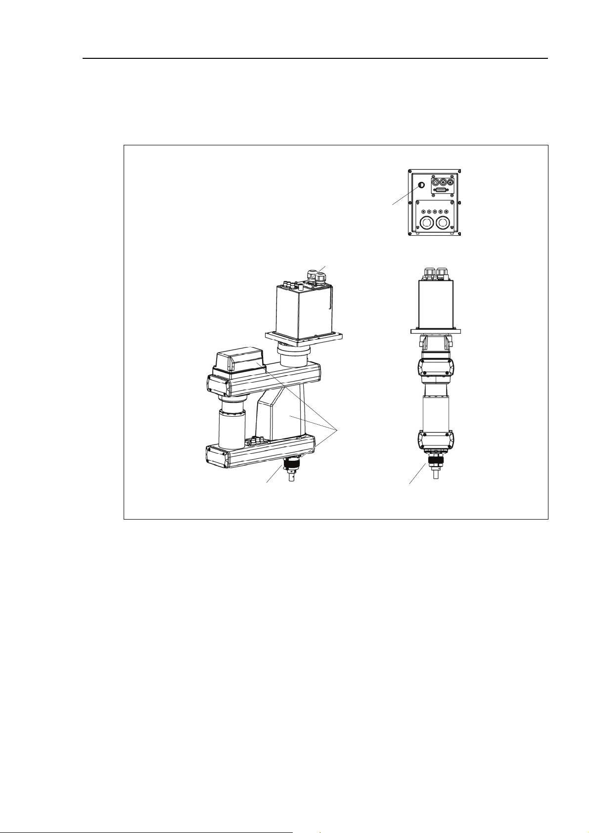
Cleanroom-model RS3-551C
The following figures show the special parts for Cleanroom-model.
These parts are different in appearance from Standard-model.
Setup & Operation 2. Specifications
Exhaust port
Exhaust port
Plate cover
(For Anti-static)
Bellows
Bellows
RS3-55 Rev.2 9
Page 20

Setup & Operation 2. Specifications Setup & Operation 2. Specifications
←
←
90 or more
90 or more
Spac e f or cab les
Spac e f or cab les
Mani pul ator
Mani pul ator
i nst allation posit ion
i nst allation posit ion
(*) indicates the stroke m argin by mecha nic al stop.
(*) indicates the stroke m argin by mecha nic al stop.
3-M 6 thr ough hole
3-M 6 thr ough hole
1 mm flat cut
1 mm flat cut
Ø3,90°
Ø3,90°
Conic al h ole
Conic al h ole
Max.ø11 thro ugh hole
Max.ø11 thro ugh hole
h7 Sh aft diameter
h7 Sh aft diameter
Mechanical stop diam eter
Mechanical stop diam eter
Enlarged view from A
Enlarged view from A
(Orig inal orientation of Joint #3, #4)
(Orig inal orientation of Joint #3, #4)
Referenc e through hole
Referenc e through hole
(View from the top of the base)
(View from the top of the base)
F or Mani pulat or mou ntin g
F or Mani pulat or mou ntin g
6-6. 5 thr ough hol e
6-6. 5 thr ough hol e
Ø11 spot faci ng d epth 6.5
Ø11 spot faci ng d epth 6.5
(from back side)
(from back side)
10 RS3-55 Rev.2 10 RS3-55 Rev.2
Page 21

2.4 Specifications
Item RS3-55 series
Setup & Operation 2. Specifications
Arm length
Max.
operating speed *1
Repeatability
Payload (Load)
Joint #4 allowable
moment of inertia *2
Max.
motion range
Arm #1, #2
Arm #1
Arm #2
Joints #1, #2
550 mm
275 mm
275 mm
7400 mm/s
Joints # 3 1100 mm/s
Joint #4 2600 deg/s
Joints #1, #2
Joints # 3
Joint #4
± 0.015 mm
± 0.01 mm
± 0.01 deg
Rated 1 kg
Max.
Rated
Max.
Joint #1
Joint #2
4 kg
0.005 kg⋅m2
0.05 kg⋅m
2
± 225 deg
± 225 deg
Joint #3 130 mm
Joint #4
Joint #1
± 720 deg
−4096000 ~ + 9557334 pulse
Max.
Joint #2
± 4177920 pulse
pulse range
(pulse)
Joint #3
Joint #4
Joint #1
− 1479112 pulse to 0 pulse
± 3145728 pulse
0.0000330deg/pulse
Joint #2 0.0000538 deg/pulse
Resolution
Joint #3 0.0000879 mm/pulse
Joint #4 0.000229 deg/pulse
Mounting ø 16 mm
Hand diameter
Hollow ø 11 mm
Mounting hole 6-M6
Weight (cables not included)
19 kg : 42 lb
Driving method AC servo motor
Joint #1 400 W
Motor power
Joint #2
400 W
consumption
Joint #3 150 W
Joint #4 100 W
RS3-55 Rev.2 11
Page 22

Setup & Operation 2. Specifications
Item RS3-55 series
Option Environment Cleanroom *3 & ESD
Joint #3 down force 150 N
Installed wire for customer use 15 wires: D-sub / 15 pin connectors
Installed pneumatic tube for customer use
2 pneumatic tubes (ø 6 mm): 0.59 Mpa (6 kgf/cm2 : 86 psi)
1 pneumatic tube (ø 4 mm): 0.59 Mpa (6 kgf/cm2 : 86 psi)
Ambient temperature
5 to 40°C (with minimum temperature variation)
Environmental
Ambient relative
requirements
10 to 80% RH (no condensation)
humidity
Noise level *4
LAeq = 70 dB(A) or less
Applicable Controller RC180, RC620
Assignable Value
( ) Default values
MTBF
SPEED
ACCEL *5
SPEEDS
ACCELS
FINE
WEIGHT
1 to (5) to100
1 to (10) to 120
1 to (50) to 2000
1 to (200) to 25000
0 to (10000) to 65000
0,130 to (1,130) to
3 years
ANSI/RIA R15.06-1999
NFPA 79 (2007 Edition)
4,130
Safety standard
CSA/CAN Z434-03 (February 2003)
CE Marking −
Machinery Directive, Low Voltage Directive, EMC
Directive
*1: In the case of PTP command. Maximum operating speed for CP command is 2000 mm/s on horizontal
plane.
*2: In the case where the center of gravity is at the center of Joint #4.
If the center of gravity is not at the center of Joint #4, set the parameter using Inertia command.
12 RS3-55 Rev.2
Page 23

Setup & Operation 2. Specifications
*3: The exhaust system in the Cleanroom-model Manipulator draws air from the base interior and arm cover
interior together.
A crack or other opening in the base unit can cause loss of negative air pressure in the outer part of the
arm, which can cause increased dust emission.
Do not remove the maintenance cover on the front of the base.
Seal the exhaust port and the exhaust tube with vinyl tape so that the joint is airtight.
If the exhaust flow is not sufficient, dust particle emission may exceed the specified maximum level.
Cleanliness level: Class ISO 3 (ISO14644-1)
In previous criteria; Clean Class: 10 or its equivalent
Amount of Dust (0.1 µm diameter or larger) in 28317 cm
3
(1cft)
sample-air around the center of the motion rang: 10 particles or
less.)
Exhaust System: Exhaust port diameter: Inner diameter: ø12 mm / Outer diameter: ø16 mm
Exhaust tube : Polyurethane tube
Outer diameter: ø12 mm (Inner diameter: ø8 mm)
or Inner diameter ø16mm or larger
Recommended exhaust flow rate: approx. 1000 cm
3
/s (Normal)
*4: Conditions of Manipulator during measurement as follows:
Operating conditions : Under rated load, 4-joints simultaneous motion, maximum speed, maximum
acceleration, and duty 50%.
Measurement point : In front of the Manipulator, 1000 mm apart from the motion range, 50 mm above
the base-installed surface.
*5: In general use, Accel setting 100 is the optimum setting that maintains the balance of acceleration and
vibration when positioning.
However, you may require an operation with high acceleration to shorten the cycle time by decreasing the
vibration at positioning. In this case, set Accel to larger than 100.
If you specify a larger Accel value, the frequency of the overload error and over heat may rise during
continuous operation. The use of large Accel setting is recommended only for necessary motions.
RS3-55 Rev.2 13
Page 24

Setup & Operation 3. Environments and Installation
Setup & Operation 3. Environments and Installation
3.2 Base Table
A base table for anchoring the Manipulator is not supplied. Please make or obtain the
base table for your Manipulator. The shape and size of the base table differs depending
on the use of the robot system. For your reference, we list some Manipulator table
requirements here.
The base table must not only be able to bear the weight of the Manipulator but also be able
to withstand the dynamic movement of the Manipulator when the Manipulator operates at
maximum acceleration. Ensure that there is enough strength on the base table by
attaching reinforcing materials such as crossbeams.
The torque and reaction force produced by the movement of the Manipulator are as
follows:
Max. Reaction torque on the horizontal plate : 500 Nm
Max. Horizontal reaction force : 1400 N
Max. Vertical reaction force : 1100 N
The threaded holes required for mounting the Manipulator base are M6. Use mounting
bolts with specifications conforming to ISO898-1 property class: 10.9 or 12.9.
For dimensions, refer to Setup & Operation: 3.3 Mounting Dimensions.
14 RS3-55 Rev.2
Page 25

3.3 Mounting Dimensions
The maximum space described in figures shows that the radius of the end effector is 50
mm or less. If the radius of the end effector exceeds 50 mm, define the radius as the
distance to the outer edge of maximum space.
If a camera or electromagnetic valve extends outside of the arm, set the maximum range
including the space that they may reach.
Be sure to allow for the following extra spaces in addition to the space required for
mounting the Manipulator, Controller, and peripheral equipment.
space for teaching
space for maintenance and inspection
Ensure a space to open the arm #1 cover, rear side cover and the maintenance
cover for maintenance.
space for cables
The minimum bend radius of the power cable is 90 mm. When installing the
Setup & Operation 3. Environments and Installation
cable, be sure to maintain sufficient distance from obstacles. In addition, leave
enough space for other cables so that they are not bent forcibly.
Ensure distance to the safeguard from the maximum motion range is more than 50 mm.
Center of Joint #3
275 mm
Maximum range
Y
X
± 225 degree
± 225 degree
Arm #1 Length
Arm #2 Length
275 mm
275 mm
RS3-551*
Joint #1 Motion range
Joint #2 Motion range
RS3-55 Rev.2 15
Page 26

Setup & Operation 3. Environments and Installation
3.4 Unpacking and Transportation
THE INSTALLATION SHALL BE PREFORMED BY QUALIFIED INSTALLATION
PERSONNEL AND SHOULD CONFORM TO ALL NATIONAL AND LOCAL
CODES.
■
Only authorized personnel should perform sling work and operate a crane
and a forklift. When these operations are performed by unauthorized
WARNING
personnel, it is extremely hazardous and may result in serious bodily injury
and/or severe equipment damage to the robot system.
■ Using a cart or similar equipment, transport the Manipulator in the same
manner as it was delivered.
■ After removing the bolts securing the Manipulator to the delivery equipment,
the Manipulator can fall. Be careful not to get hands or fingers caught.
CAUTION
■ The arm is secured with a wire tie. Leave the wire tie secured until you
finish the installation so as not to get hands or fingers caught.
■ To carry the Manipulator, have two or more people to work on it and secure
the Manipulator to the delivery equipment or hold the areas indicated in gray
in the figure (bottom of Arm #1 and bottom of the base) by hand.
When holding the bottom of the base by hand, be very careful not to get
your hands or fingers caught.
RS3-551* : approx. 19 kg : 42 lb.
■ Stabilize the Manipulator with your hands when hoisting it.
■ When transporting the Manipulator for a long distance, secure it to the
delivery equipment directly so that the Manipulator never falls.
If necessary, pack the Manipulator in the same style as it was delivered.
16 RS3-55 Rev.2
Page 27

Setup & Operation 3. Environments and Installation
3.7 User Wires and Pneumatic Tubes
■
Only authorized or certified personnel should be allowed to perform wiring.
CAUTION
Wiring by unauthorized or uncertified personnel may result in bodily injury and/or
malfunction of the robot system.
User electrical wires and pneumatic tubes are contained in the cable unit.
Electrical Wires
Rated Voltage
Allowable
Current
Wires Nominal Sectional Area Outer Diameter Note
AC/DC30 V 1 A 15 0.211 mm2 ø8.3±0.3 mm Shielded
Maker Standard
15 pin
Suitable Connector JAE DA-15PF-N (Solder type)
Clamp Hood JAE
DA-C8-J10-F2-1R (Connector setscrew: #4-40 NC)
Pins with the same number, indicated on the connectors on both ends of the cables, are
connected.
Pneumatic Tubes
Max. Usable Pneumatic Pressure Pneumatic Tubes Outer Diameter × Inner Diameter
0.59 MPa (6 kgf/cm2 : 86 psi)
2 ø6 mm × ø4 mm
1 ø4 mm × ø2.5 mm
Fittings for ø6 mm and ø4 mm (outer diameter) pneumatic tubes are supplied on both ends
of the pneumatic tubes.
User connector
(15-pin D-sub connector)
Fitting (white)
Fitting (white)
for ø4 mm
pneumatic tube
User connector
(15-pin D-sub connector)
Fitting (black)
for ø6 mm
pneumatic tube
Fitting (white)
for ø4 mm pneumatic tube
Fitting (blac k)
for ø6 mm pneumatic tube
Fitting (white)
for ø6 mm pneumatic tub e
Joint #3
break release switch
for ø4 mm
pneumatic tube
NOTE
The Joint #4 (rotating) motion range is ±720 degrees. Be careful not to let the
wires/tubes caught in the end effector.
RS3-55 Rev.2 17
Page 28

Setup & Operation 4. Setting of End Effectors
Setup & Operation 4. Setting of End Effectors
4.2 Attaching Cameras and Air valves
Arm #2 has threaded holes as shown in the figure below. Use these holes for attaching
cameras, air valves, and other equipment.
[Unit: mm]
4-M4 depth5
4-M4 depth5
NOTE
- When cameras and air valves are attached, it can limit the motion range by wires and
pneumatic tubes. Take extra care when designing and attaching.
- The Joint #4 (rotating) motion range is ±720 degrees. Be careful not to let the
wires/tubes caught in the end effector.
18 RS3-55 Rev.2
Page 29

4.3 Weight and Inertia Settings
4.3.1 Weight Setting
■
The total weight of the end effector and the work piece must not exceed 3 kg.
The RS series Manipulators are not designed to work with loads exceeding 3 kg.
Setup & Operation 4. Setting of End Effectors
CAUTION
(%)
Always set the Weight parameters according to the load. Setting a value that is
smaller than the actual load may cause errors, excessive shock, insufficient
function of the Manipulator, and/or shorten the life cycle of parts/mechanisms.
The acceptable weight capacity (end effector and work piece) in RS series is 1 kg at the
default rating and 3 kg at the maximum. When the load (weight of the end effector and
work piece) exceeds the rating, change the setting of Weight parameter.
After the setting is changed, the maximum acceleration/deceleration speed of the robot
system at PTP motion corresponding to the “Weight Parameter” is set automatically.
Automatic speed setting by Weight
140
120
100 100 100 100
100
80
60
40
* The percentage in
100
the graph is based
on the speed at rated
weight (1 kg) as
100%.
(%)140
120
100
80
60
40
20
20
0 0.5 1 1.5 2 2.5 3 3.5 4 (kg)
Wei g h t sett ing
Automatic acceleration/deceleration setting by Weight
120
120
100
0
40
0.5 1 1.5 2 2.5 3 3.5 4 (kg) Weight sett in g
* The per centage in the
graph is based on the
acceleration /
deceleration at rated
weight (1 kg) as 100%.
30
RS3-55 Rev.2 19
Page 30

Setup & Operation 4. Setting of End Effectors
4.3.2 Inertia Setting
Automatic acceleration/deceleration setting by Inertia (eccentric quantity)
120
(%)
100
80
60
40
20
100
80
40
* The percentage in the graph is based
on the acceleration/deceleration at
rated eccentricity (0 mm) as 100%.
20
0 25 5 0 75 100 (mm) Eccentricity setting
4.4 Precautions for Auto Acceleration/Deceleration of Joint #3
When you move the Manipulator in horizontal PTP motion with Joint #3 (Z) at a high
position, the motion time will be faster.
When Joint #3 gets below a certain point, then auto acceleration/deceleration is used to
reduce acceleration/deceleration. (Refer to the figure below.) The higher the position of
the shaft is, the faster the motion acceleration/deceleration is. However, it takes more
time to move Joint #3 up and down. Adjust the position of Joint #3 for the Manipulator
motion after considering the relation between the current position and the destination
position.
The upper limit of Joint #3 during horizontal motion using Jump command can be set by
the LimZ command.
Automatic acceleration/deceleration vs. Joint #3 position
120
(%)
100
80
60
40
100
100
50
* The percentage in the gr aph is
based on the acceleration /
deceleration at the upper-limited
position of Joint #3
20
Height of the shaft
NOTE
0 -20 -60 -100 -140 (mm)
When moving the Manipulator horizontally while the shaft is being lowered, it may cause
over-shoot at the time of final positioning.
20 RS3-55 Rev.2
Page 31

Setup & Operation 5. Motion Range
5.1 Motion Range Setting by Pulse Range
5.1.1 Max. Pulse Range of Joint #1
The 0 (zero) pulse position of Joint #1 is the position where Arm #1 faces toward the
positive (+) direction on the X-coordinate axis.
When the 0 pulse is a starting point, the counterclockwise pulse value is defined as the
positive (+) and the clockwise pulse value is defined as the negative (-).
View from
this point
Setup & Operation 5. Motion Range
0 pulse
A : Max. motion range : ± 225 °
B : Max. pulse range : −4096000 to + 9557334 pulse
RS3-55 Rev.2 21
Page 32

Setup & Operation 5. Motion Range
5.4 Standard Motion Range
The following “motion range” diagrams show the standard (maximum) specification.
When each Joint motor is under servo control, the center of Joint #3’s (shaft’s) lowest
point moves in the areas shown in the figure.
“Area limited by mechanical stop” is the area where the center of Joint #3’s lowest point
can be moved when each joint motor is not under servo control.
“Mechanical stop” sets the limited motion range so that the center of Joint #3 cannot move
beyond the area mechanically.
Motion range
Center of Joint #3
Type
(unit: mm)
n : Joint #3 range to hit upper mechanical stop
m : Joint #3 strok e
p : Joint #3 range to hit lower mechanical stop
22 RS3-55 Rev.2
Page 33

Setup & Operation 5. Motion Range
Maintenance 14. Maintenance Parts List
14.1 Common Parts
Part Name Code Note
Joint #1
AC
Servo Motor
Reduction Gear
Unit
Solenoid Brake Joint #3
Timing Belt
Battery Board
Battery Unit
O-ring
Joint #2
Joint #3
Joint #4
Joint #1
Joint #2
Joint #3
Joint #1
Joint #2
Joint #3
Joint #4
Joint #1
Joint #2
Joint #1
Joint #2
R13B000616
R13B000616
R13B000615
R13B000617
R13B010029
R13B010019
R13B010020
R13B030503
R13B030216
R13B030217
R13B030218
R13B030219
R13B041203
R13ZA00600300
R13B031206 O-ring S90A
R13B031236
R13B031237 O-ring S30A
R13A031200700 O-ring S71A
400 W
400 W
150 W
100 W
Width 15 mm Length 270 mm
Width
Width
Width
No lithium battery
Installed in Base
Spare lithium battery
ER17330V (TOSHIBA)
O-ring S65A
10 mm
9 mm
12 mm
Length
Length
Length
246 mm
246 mm
339 mm
Joint #2
Ball Screw Spline
Grease
Oil seal unit (Arm #2)
M/C cable
LED Lamp
Brake Release Switch
Ball Screw Spline
Cable Unit
Arm#2 Cover
RS3-55 Rev.2 23
Reduction Gear Unit
Cable
Cable Length 3 m
Cable Length 5 m
Cable Length 10 m
R13B031238
R13ZA00330200
R13ZA00330100
R13B030304
R13B031239
R12B020434
R12B020435
R12B020436
R13B030004
R13Z702640100
R13B010222
R13B020054
R13B030425
O-ring S53A
AFB grease (400 g)
SK-1A (500 g)
GPL-224 (227g)
Page 34

Maintenance 14. Maintenance Parts List
14.2 Parts by Environment Model
14.2.1 S: Standard-model
Part Name Code Note
Ball Screw Spline
Cable Unit R13B020054
Arm#2 Cover R13B030425
14.2.2 C: Cleanroom-model
Part Name Code Note
Ball Screw Spline R13B010222
Cable Unit R13B020054
Arm#2 Cover R13B030425
Bellows R13B010222
Gasket Unit R13B020054
Liquid gasket R13B030425
R13B010222
24 RS3-55 Rev.2
 Loading...