

Page 1
Rev.26 EM208C4443F
ROBOT CONTROLLER
RC90 / RC90-B
(EPSON RC+ 7.0)
Page 2

ROBOT CONTROLLER RC90 / RC90-B (EPSON RC+ 7.0) Rev.26
Page 3

ROBOT CONTROLLER
RC90 / RC90-B
(EPSON RC+ 7.0)
Rev.26
Copyright © 2013-2020 SEIKO EPSON CORPORATION. All rights reserved.
RC90 / RC90-B (EPSON RC+ 7.0) Rev.26 i
Page 4

FOREWORD
1. Damage or malfunction caused by improper use which is not described in the manual, or
careless use.
2. Malfunctions caused by customers’ unauthorized disassembly.
3. Damage due to improper adjustments or unauthorized repair attempts.
4. Damage caused by natural
1. If the robot system associated equipment is used outside of the usage conditions and
product specifications described in the manuals, this warranty is void.
2. If you do not follow the WARNINGS and CAUTIONS in this manual, we cannot be
responsible for any malfunction or accident, even if the result is injury or death.
3. We cannot foresee all possible dangers and consequences. Therefore, this manual cannot
warn the user of al
Thank you for purchasing our robot products.
This manual contains the information necessary for the correct use of the robot controller.
Please carefully read this manual and other related manuals before installing the robot
system.
Keep this manual handy for easy access at all times.
WARRANTY
The robot system and its optional parts are shipped to our customers only after being
subjected to the strictest quality controls, tests, and inspections to certify its compliance with
our high performance standards.
Product malfunctions resulting from normal handling or operation will be repaired free of
charge during the normal warranty period. (Please contact the supplier of your region for
warranty period information.)
However, customers will be charged for repairs in the following cases (even if they occur
during the warranty period):
disasters such as earthquake, flood, etc.
Warnings, Cautions, Usage:
l possible hazards.
ii RC90 / RC90-B (EPSON RC+ 7.0) Rev.26
Page 5

TRADEMARKS
Microsoft, Windows, and Windows logo are either registered trademarks or trademarks of
Microsoft Corporation in the United States and/or other countries. Other brand and
product names are trademarks or registered trademarks of the respective holders.
TRADEMARK NOTATION IN THIS MANUAL
Microsoft® Windows® 8 Operating system
Microsoft® Windows® 10 Operating system
Throughout this manual, Windows 8, and Windows 10 refer to above respective
operating systems. In some cases, Windows refers generically to Windows 8, and
Windows 10.
NOTICE
No part of this manual may be copied or reproduced without authorization.
The contents of this manual are subject to change without notice.
Please notify us if you should find any errors in this manual or if you have any comments
regarding its contents.
MANUFACTURER
CONTACT INFORMATION
Contact information is described in “SUPPLIERS” in the first pages of the following
manual:
Robot System Safety and Installation Read this manual first
RC90 / RC90-B (EPSON RC+ 7.0) Rev.26 iii
Page 6

Before Reading This Manual
NOTE
NOTE
NOTE
NOTE
Do not connect the followings to the TP/OP port of RC90 / RC90-B. Connecting to the
followings may result in malfunction of the device since the pin assignments are different.
OPTIONAL DEVICE dummy plug
Operation Pendant OP500
Operator Pendant OP500RC
Jog Pad JP500
Teaching Pendant TP-3**
Operator Panel OP1
For RC90 / RC90-B, be sure to install the EPSON RC+ 7.0 to the development PC first,
then connect the development PC and RC90 / RC90-B with the USB cable.
If RC90 / RC90-B and the development PC are connected without installing the EPSON
RC+ 7.0 to the development PC, [Add New Hardware Wizard] appears. If this wizard
appears, click the <Cancel> button.
Concerning the security support for the network connection:
The network connecting function (Ethernet) on our products assumes the use in the local
network such as the factory LAN network. Do not connect to the external network such as
Internet.
In addition, please take security measure such as for the virus from the network connection
by installing the antivirus software.
Security support for the USB memory:
Make sure the USB memory is not infected with virus when connecting to the Controller.
iv RC90 / RC90-B (EPSON RC+ 7.0) Rev.26
Page 7
Label
Controller
Software
RC90 controller firmware
Ver.7.0.2.0 or later
Before Ver.7.0.1
!!!
Ver.7.0.2 or later
OK
RC90-B controller firmware
Ver.7.4.2.0 or later
Before Ver.7.4.1
!!!
Ver.7.4.2 or later
OK
NOTE
NOTE
NOTE
Control System Configuration
This manual explains with the following combinations of Controllers and software.
Robot Controller RC90 with the following label attached:
RC90
EPSON RC+ 7.0
EPSON RC+ 7.0
OK: Compatible All functions of the EPSON RC+ 7.0 and the Controller are available.
!!!: Compatible Connection is OK. We recommend using EPSON RC+7.0 Ver. 7.0.2 or later.
Robot Controller RC90-B:
EPSON RC+ 7.0
OK: Compatible All functions of the EPSON RC+ 7.0 and the Controller are available.
!!!: Compatible Connection is OK. We recommend using EPSON RC+7.0 Ver. 7.4.2 or later.
There is no label on RC90-B.
Manual PDF for this robot system is available from EPSON RC+ 7.0 Ver. 7.0.2
This option is not available for Robot Controller RC90 (EPSON RC+ 5.0) without the label.
RC90 / RC90-B (EPSON RC+ 7.0) Rev.26 v
Page 8

vi RC90 / RC90-B (EPSON RC+ 7.0) Rev.26
Page 9

Safety
1. Safety 3
2. Conventions 3
3. Safety Precautions 4
Setup & Operation
1. Specifications 9
1.1 System Example ......................................................................................9
1.2 Standard Specifications .........................................................................10
1.3 Outer Dimensions ..................................................................................12
2. Part Names and Functions 13
Table of Contents
2.1 Part Names ............................................................................................13
2.2 Functions ...............................................................................................13
2.3 LED ........................................................................................................15
2.4 Safety Features......................................................................................16
3. Installation 18
3.1 Unpacking ..............................................................................................18
3.2 Environmental Requirements ................................................................18
3.2.1 Environment ...............................................................................18
3.2.2 Installation ..................................................................................19
3.3 Power Supply .........................................................................................20
3.3.1 Specifications .............................................................................20
3.3.2 AC Power Cable .........................................................................21
3.3.3 M/C Power Cable .......................................................................22
3.4 Cable Connection ..................................................................................23
3.4.1 Typical Cable Connection ..........................................................24
3.4.2 Connecting Manipulator to Controller ........................................26
3.5 Noise Countermeasures ........................................................................28
4. Operation Mode (TEACH/AUTO/TEST) 29
4.1 Overview ................................................................................................29
4.2 Switch Operation Mode .........................................................................29
4.3 Program Mode (AUTO) ..........................................................................30
4.3.1 What is Program Mode (AUTO)? ...............................................30
RC90 / RC90-B (EPSON RC+ 7.0) Rev.26 vii
Page 10

Table of Contents
4.3.2 Setup from EPSON RC+ 7.0 ..................................................... 30
4.4 Auto Mode (AUTO) ................................................................................ 31
4.4.1 What is Auto mode (AUTO)? ..................................................... 31
4.4.2 Setup from EPSON RC+ 7.0 ..................................................... 31
4.4.3 Setup from Control Device ......................................................... 32
5. Development PC Connection Port 33
5.1 About Development PC Connection Port .............................................. 33
5.2 Precaution .............................................................................................. 34
5.3 Software Setup and Connection Check ................................................ 34
5.4 Disconnection of Development PC and Controller ................................ 35
6. Memory Port 36
6.1 What is Controller Status Storage Function? ........................................ 36
6.2 Before Using Controller Status Storage Function ................................. 36
6.2.1 Precautions ................................................................................ 36
6.2.2 Adoptable USB Memory ............................................................ 36
6.3 Controller Status Storage Function ....................................................... 37
6.3.1 Controller Status Storage with Trigger Button ........................... 37
6.3.2 Load Data with EPSON RC+ 7.0 ............................................... 37
6.3.3 Transfer with E-mail ................................................................... 39
6.4 Details of Data ....................................................................................... 39
7. LAN (Ethernet Communication) Port 40
7.1 About the LAN (Ethernet Communication) Port .................................... 40
7.2 IP Address ............................................................................................. 40
7.3 Changing Controller IP Address ............................................................ 41
7.4 Connection of Development PC and Controller with Ethernet .............. 42
7.5 Disconnection of Development PC and Controller with Ethernet ......... 43
8. TP Port 44
8.1 What is the TP Port? ............................................................................. 44
8.2 Teach Pendant Connection ................................................................... 44
9. EMERGENCY 45
9.1 Safety Door Switch and Latch Release Switch ..................................... 45
9.1.1 Safety Door Switch .................................................................... 46
9.1.2 Latch Release Switch ................................................................ 46
9.1.3 Checking Latch Release Switch Operation ............................... 47
viii RC90 / RC90-B (EPSON RC+ 7.0) Rev.26
Page 11

Table of Contents
9.2 Emergency Stop Switch Connection .....................................................48
9.2.1 Emergency Stop Switch .............................................................48
9.2.2 Checking Emergency Stop Switch Operation ............................48
9.2.3 Recovery from Emergency Stop ................................................48
9.3 Pin Assignments ....................................................................................49
9.4 Circuit Diagrams ....................................................................................50
9.4.1 Example 1: External emergency stop switch typical application50
9.4.2 Example 2: External safety relay typical application..................51
10. Standard RS-232C Port 52
10.1 About the RS-232C Port ......................................................................52
10.2 Confirmation with EPSON RC+ 7.0 (RS-232C) ..................................52
10.3 RS-232C Software Communication Setup (RS-232C) .......................53
10.4 Communication Cable (RS-232C) .......................................................53
11. I/O Connector 54
11.1 RC90 (I/O Connector) ..........................................................................55
11.1.1 Input Circuit (RC90) .................................................................55
11.1.2 Output Circuit (RC90)...............................................................57
11.2 RC90-B (I/O Connector) ......................................................................60
11.2.1 Input Circuit (RC90-B) ..............................................................60
11.2.2 Output Circuit (RC90-B) ...........................................................62
11.3 Pin Assignments ..................................................................................64
12. I/O Remote Settings 65
12.1 I/O Signal Description ..........................................................................66
12.1.1 Remote Input Signals ...............................................................66
12.1.2 Remote Output Signals ............................................................70
12.2 Timing Specifications ...........................................................................73
12.2.1 Design Notes for Remote Input Signals...................................73
12.2.2 Timing Diagram for Operation Execution Sequence ...............73
12.2.3 Timing Diagram for Program Execution Sequence .................73
12.2.4 Timing Diagram for Safety Door Input Sequence ....................74
12.2.5 Timing Diagram for Emergency Stop Sequence .....................74
13. Option Slots 75
13.1 About Option Slots ...............................................................................75
13.2 Expansion I/O Board ............................................................................75
13.2.1 About Expansion I/O Board .....................................................75
RC90 / RC90-B (EPSON RC+ 7.0) Rev.26 ix
Page 12

Table of Contents
13.2.2 Board Configuration (Expansion I/O)....................................... 75
13.2.3 Confirmation with EPSON RC+ 7.0 ......................................... 76
13.2.4 Input Circuit .............................................................................. 76
13.2.5 Output Circuit ........................................................................... 78
13.2.6 Pin Assignments ...................................................................... 81
13.3 Fieldbus I/O Board ............................................................................... 82
13.4 RS-232C Board ................................................................................... 82
13.4.1 RS-232C Board ........................................................................ 82
13.4.2 Board Setup (RS-232C) ........................................................... 82
13.4.3 Confirmation with EPSON RC+ 7.0 (RS-232C) ...................... 83
13.4.4 RS-232C Software Communication Setup (RS-232C) ............ 83
13.4.5 Communication Cable (RS-232C) ........................................... 84
13.5 Analog I/O Board ................................................................................. 85
13.5.1 About Analog I/O Board ........................................................... 85
13.5.2 Board Configuration (Analog I/O Board) ................................. 86
13.5.3 Confirmation with EPSON RC+ (Analog I/O Board) ................ 89
13.5.4 Input Circuit (Analog I/O Board) .............................................. 90
13.5.5 Output Circuit (Analog I/O Board) ............................................ 90
13.5.6 Pin Assignments (Analog I/O Board) ....................................... 91
13.6 EUROMAP67 Board ............................................................................ 92
13.6.1 Notes on the EUROMAP67 Board .......................................... 93
13.6.2 Board Settings (EUROMAP67 Board) ..................................... 95
13.6.3 Installation (EUROMAP67 Board) ........................................... 95
13.6.4 Confirming with EPSON RC+ 7.0 (EUROMAP67 Board) ....... 97
13.6.5 Sample Project (EUROMAP67 Board) .................................... 97
13.6.6 Circuit Overview (EUROMAP67 Board) .................................. 98
13.6.7 Input Circuit (EUROMAP67 Board) ......................................... 99
13.6.8 Output Circuit (EUROMAP67 Board) ...................................... 99
13.6.9 Emergency Stop, Safeguard (EUROMAP67 Board) ............. 100
13.6.10 I/O Pin Assignments (EUROMAP67 Board) ........................ 101
13.6.11 Emergency stop connecter Pin Assignments
(EUROMAP67 Board) ......................................................... 102
x RC90 / RC90-B (EPSON RC+ 7.0) Rev.26
Page 13

Maintenance
Table of Contents
1. Safety Precautions on Maintenance 107
1.1 Safety Precautions .............................................................................. 107
1.2 Lockout / Tagout ................................................................................. 108
2. Regular Maintenance Inspection 110
3. Controller Structure 111
3.1 Location of Parts ................................................................................. 111
3.1.1 RC90 (for LS3, LS6) ................................................................ 111
3.1.2 RC90 (for LS20) ...................................................................... 111
3.1.3 RC90-B (for LS3-B, LS6-B) ..................................................... 112
3.1.4 RC90-B (for LS10-B, LS20-B) ................................................. 112
3.2 Diagram of Cable Connections ........................................................... 113
3.2.1 RC90 (for LS3, LS6), RC90-B( for LS3-B, LS6-B) .................. 113
3.2.2 RC90 (for LS20), RC90-B (for LS10-B, LS20-B) .................... 114
4. Backup and Restore 115
4.1 What is the Backup Controller Function? ........................................... 115
4.2 Backup Data Types ............................................................................ 115
4.3 Backup ................................................................................................ 116
4.4 Restore ............................................................................................... 117
5. Firmware Update 120
5.1 Updating Firmware ............................................................................. 120
5.2 Firmware Upgrade Procedure ............................................................ 120
5.3 Controller Recovery ............................................................................ 123
5.4 Firmware Initialization Procedure ....................................................... 124
5.5 Adding Confirmation Steps by Strengthening Security of EtherNet
Connection .......................................................................................... 126
RC90 / RC90-B (EPSON RC+ 7.0) Rev.26 xi
Page 14

Table of Contents
6. Alarm 130
6.1 Before Controller Firmware Ver.7.1.8.x ............................................... 131
6.1.1 Alarm Configuration ................................................................. 131
6.1.2 How to View the Alarm Information ......................................... 132
6.1.3 How to Edit the Alarm Information ........................................... 133
6.1.4 Alarm Notifying Method ........................................................... 133
6.1.5 How to Cancel the Alarm ......................................................... 134
6.2 Controller Firmware Ver.7.2.0.x or later .............................................. 135
6.2.1 Maintenance Information ......................................................... 135
6.2.2 How to View the Maintenance Information .............................. 136
6.2.3 How to Edit the Maintenance Information ............................... 138
6.2.4 Alarm Notifying Method ........................................................... 139
6.2.5 How to Cancel the Alarm ......................................................... 139
7. Maintenance Parts Replacement Procedures 140
7.1 Fan Filter .............................................................................................. 141
7.2 Fan ....................................................................................................... 142
7.3 Battery ................................................................................................. 143
7.4 CF (Compact Flash) ............................................................................ 145
7.5 MDB ..................................................................................................... 146
7.6 DMB ..................................................................................................... 148
7.7 DMB Sub Board ................................................................................... 152
7.8 DPB...................................................................................................... 153
7.9 Option Board........................................................................................ 155
8. Verifying Robot System Operation 157
9. Troubleshooting 158
9.1 Error Code Table ................................................................................. 158
9.2 Cannot Connect the Development PC and the Controller using the USB
cable .................................................................................................... 291
9.2.1 Confirmation Using Windows Device Manager ....................... 292
9.2.2 When recognized under “Other devices”
in Windows Device Manager ................................................... 294
10. Maintenance Parts List 295
xii RC90 / RC90-B (EPSON RC+ 7.0) Rev.26
Page 15

Safety
This section contains information for safety of the Robot System.
Page 16

Page 17
1. Safety
Installation and transportation of robots and robotic equipment shall be performed by
qualified personnel and should conform to all national and local codes.
Please read this manual and other related manuals before installing the robot system or
before connecting cables. Keep this manual in a handy location for easy access at all times.
2. Conventions
Important safety considerations are indicated throughout the manual by the following
symbols. Be sure to read the descriptions shown with each symbol.
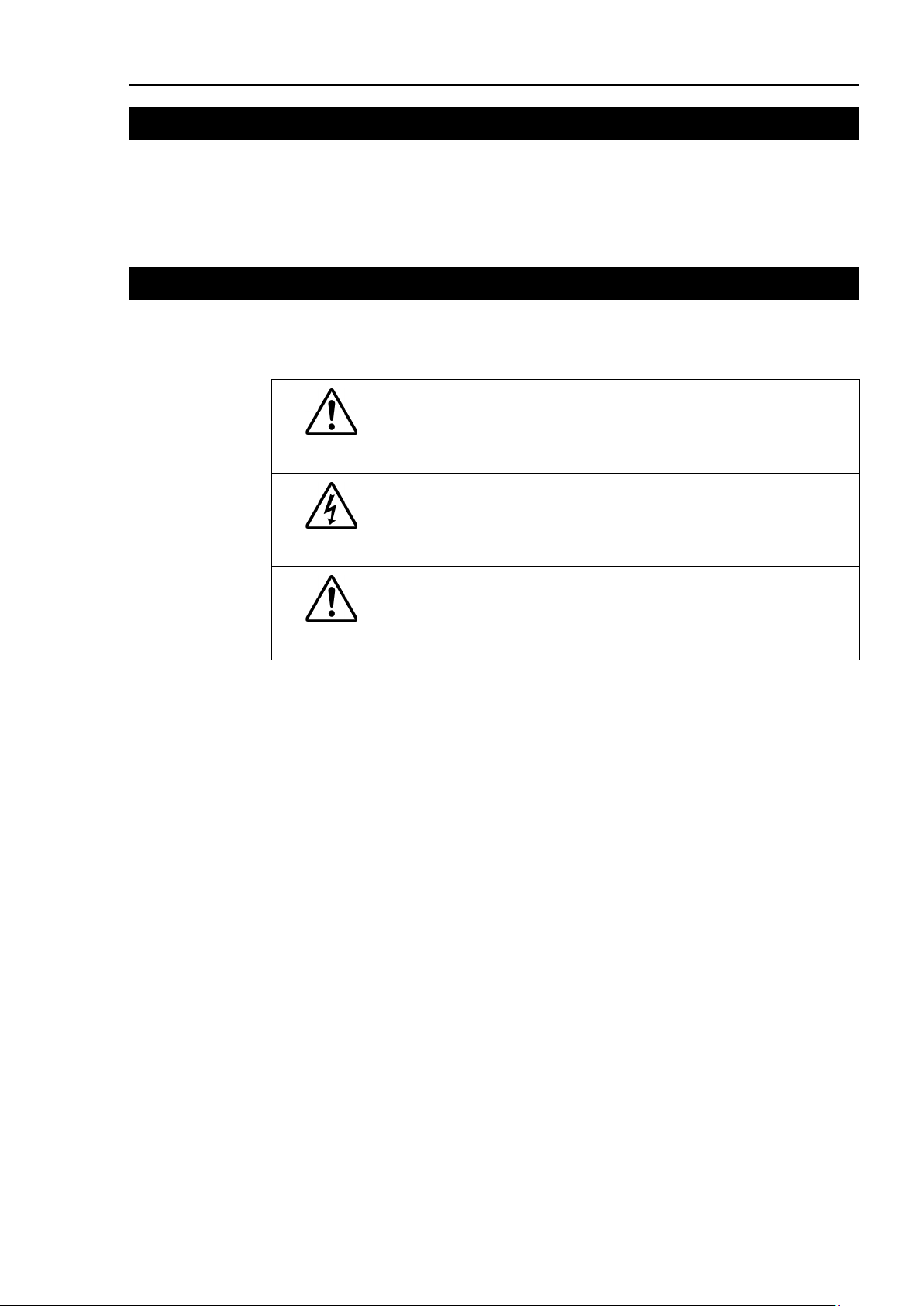
WARNING
WARNING
Safety 1. Safety
This symbol indicates that a danger of possible serious injury or death
exists if the associated instructions are not followed properly.
This symbol indicates that a danger of possible harm to people caused
by electric shock exists if the associated instructions are not followed
properly.
CAUTION
This symbol indicates that a danger of possible harm to people or
physical damage to equipment and facilities exists if the associated
instructions are not followed properly.
RC90 / RC90-B (EPSON RC+ 7.0) Rev.26 3
Page 18
Safety 3. Safety Precautions
Personnel
read the Safety chapter in User
before designing and/or constructing the robot system. Designing and/or
constructing the robot system withou
extremely hazardous, may result in serious bodily injury and/or severe equipment
damage to the robot system, and may cause serious safety problems.
The Manipulator and the Controller must be used within the environmental
conditions described in their respective manuals. This product has been
designed and manufactured strictly for use in a normal indoor environment.
Using the product in an environmen
conditions may not only shorten the life cycle of the
serious safety problems.
The
the manuals.
may
problem
The interlock of the Safety Door must be functioning when the
operated.
be turned ON/OFF. (I.E. the condition where the switch is disabled)
(Example: Tape is put around the switch to hold it closed.) Operating the robot
system when the s
may
s as the Safety Door input cannot fulfill its
intended function
Connect input signal wires for Emergency Stop and Safety Door to the
EMERGENCY connector so that the Emergency Stop switch in the Teach
Pendant connected to the TP port always functions. (Refer to the typical
application diagram in Setup & Operation 9.4
3. Safety Precautions
Only trained personnel should design and install the robot system.
Trained personnel are defined as those who have taken robot system training class held by
the manufacturer, dealer, or local representative company, or those who understand the
manuals thoroughly and have the same knowledge and skill level as those who have
completed the training courses.
The following items are safety precautions for qualified design or installation
personnel:
WARNING
who design and/or construct the robot system with this product must
’s Guide to understand the safety requirements
t understanding the safety requirements is
t that exceeds the specified environmental
product but may also cause
robot system must be used within the installation requirements described in
Using the robot system outside of the installation requirements
not only shorten the life cycle of the product but also cause serious safety
s.
robot system is
Do not operate the system under the condition that the switch cannot
witch is not functioning properly is extremely hazardous and
cause serious safety problem
.
Circuit Diagrams.)
4 RC90 / RC90-B (EPSON RC+ 7.0) Rev.26
Page 19
Do not open the cover(s) of the Controller except while maintaining it. Opening
the cover(s) of the Controller is extremely hazardous and may result in electric
shock even when its main power is OFF because of t
the Controller.
Make sure that the power to the Controller is turned OFF before connecting or
disconnecting any cables. Connecting or disconnecting any cables with the
power ON is extremely hazardous and may result in electric shock and/or
malfunction of the Controller.
Be sure to connect the cables properly. Do not allow unnecessary strain on the
cables. (Do not put heavy objects on the cables. Do not bend or pull the cables
forcibly.) The unnecessary strain on the cables may result in damage to the
cables, disconnection, and/or contact failure. Damaged cables, disconnection,
or a contact failure is extremely hazardous and may result in electric shock and/or
improper function of the system.
When connecting the plug to fit the outlet in your factory, make sure that it is done
by qualified personnel. When connecting the plug, be sure to connect the earth
wire of the AC power cable colored green/yellow on the Controller to the earth
termin
at all times to avoid the risk of electric shock. Always use a power plug and
receptacle. Never connect the Controller directly to the factory power supply.
(Field wiring)
The serial number of the Manipulator that should be connected is indicated on the
Connection Check Label on the Controller. Connect the Controller and the
Manipulator correctly. Improper connection between the Controller and the
Manipulator may
problems.
When using remote I/O, always make sure of the following. Using the robot
system under
conditions may cause malfunction of the system
and/or safety problems.
-
-
- When verifying the robot system operation, prepare for failures with initial
WARNING
Safety 3. Safety Precautions
The following items are safety precautions for qualified design or installation
personnel: (cont.)
he high voltage charge inside
CAUTION
al of the factory power supply. The equipment must be grounded properly
cause improper function of the robot system and also safety
unsatisfactory
Assign remote functions to inputs/outputs correctly and wire correctly when
setting up remote I/O signals.
Make sure that the functions correspond to the correct input/output signals
before turning ON the system.
RC90 / RC90-B (EPSON RC+ 7.0) Rev.26 5
settings or wiring. If the Manipulator functions unusually by the failures with
initial settings or wiring, press the Emergency Stop switch immediately to stop
the Manipulator.
Page 20
Safety 3. Safety Precautions
The interlock of the Safety Door must be functioning when the
operated.
be turned ON/OFF. (I.E. the condition where the switch is disabled)
(Example: Tape is put around the switch to hold it closed.) Operating the robot
system when the switch is not
is extremely hazardous and
may
s as the Safety Door input cannot fulfill its
intended function
Do not open the cover(s) of the Control
the cover(s) of the Controller is
and may result in electric
shock
the Control
The following items are safety precautions for qualified operator personnel:
WARNING
WARNING
robot system is
Do not operate the system under the condition that the switch cannot
functioning properly
cause serious safety problem
.
ler except while maintaining it. Opening
extremely hazardous
even when its main power is OFF because of the high voltage charge inside
ler.
6 RC90 / RC90-B (EPSON RC+ 7.0) Rev.26
Page 21

Setup & Operation
This section contains information for setup and operation of the Robot Controller.
Page 22

Page 23
Setup & Operation 1. Specifications
*1 EPSON RC+ 7.0 supports the following OS
Wi
ndows 8.1 Pro
(EPSON RC+7.0 Ver.7.1.0
or later
)
Windows 10 Pro
(EPSON RC+7.0 Ver.7.2.0 or later)
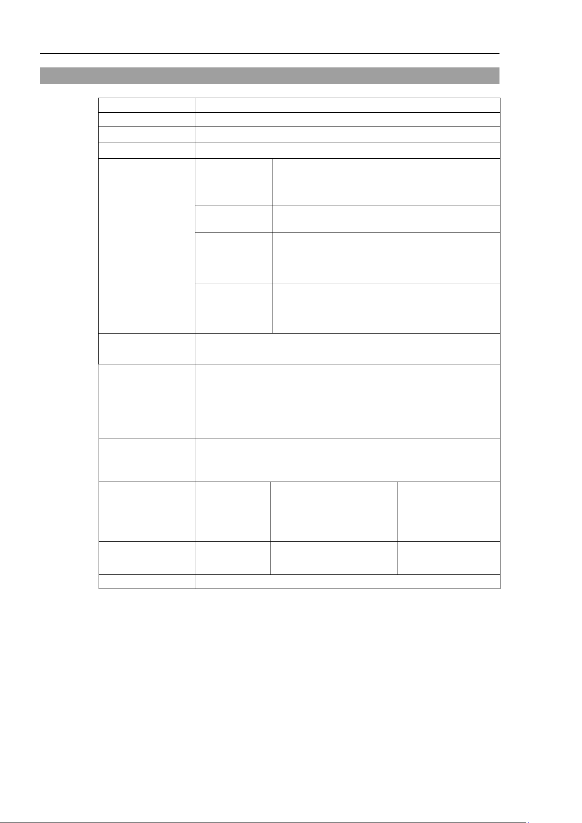
Operation panel
Motion Controller
RC90 / RC90-B
Expansion I/O Board
Fieldbus
PROFIBUS-DP
DeviceNet
CC-Link
EtherNet/IP
PROFINET
EtherCAT
RS-232C Board
Windows *1
PC
EPSON RC+ 7.0
Software
Option
USB 2.0
or
Ethernet
TP2
(Option)
Standard I/O
Remote I/O
Ethernet
RS-232C
Requires preparation
by users
LS / LS-B series
PLC (Sequencer)
Option
Standard
PG Board
TP1
(Option)
AnalogI/O Board
EUROMAP67 Board
1. Specifications
1.1 System Example
RC90 / RC90-B (EPSON RC+ 7.0) Rev.26 9
Page 24
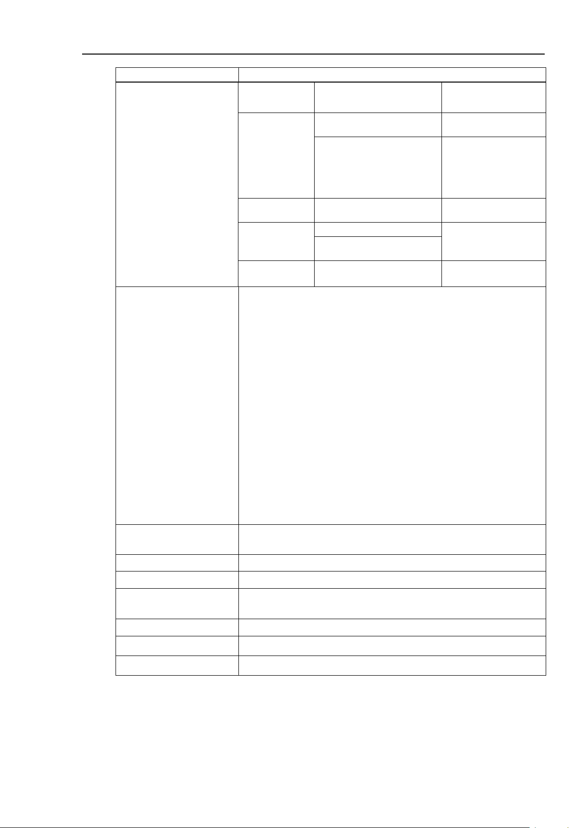
Setup & Operation 1. Specifications
Item
Specification
Model
Robot Controller RC90 / RC90-B
Controllable axes
4 AC servo motors
Programming
software
Up to 4 joints simultaneous control
Software AC servo control
PTP motion : Programmable in the range of
to be manually entered.)
PTP motion : Programmable in the range of
to be manually entered.)
Maximum Object Size : 4 MB
of array variables.)
Including 8 inputs,
allowed
RS-232C port
1 port
1.2 Standard Specifications
CPU 32 bits Micro Processor
Robot manipulator
control
Positioning control
Memory capacity
Teaching method
language and
Robot control
Joint Control
Speed Control
Acceleration/
deceleration
control
PTP (Point-To-Point control)
CP (Continuous Path control)
Point data area : 1000 points (per file)
Backup variable area : Max. 100 KB (Includes the memory area for
Remote
Direct
MDI (Manual Data Input)
EPSON RC+ 7.0 (multi-tasking robot language)
Ver.7.0.2 or later is recommended.
1 to 100%
CP motion : Programmable (Actual value
1 to 100%; Automatic
CP motion : Programmable (Actual value
the management table.)
Approx. 1000 variables (Depends on the size
External
input/output
signals (standard)
Communication
interface (standard)
10 RC90 / RC90-B (EPSON RC+ 7.0) Rev.26
Standard I/O
Ethernet 1 channel
Input : 24
Output : 16
8 outputs with remote
function assigned
Assignment change
Page 25
Setup & Operation 1. Specifications
Item
Specification
Addition of
2 boards allowed
EtherCAT
1 board from the left
Controllable joints
4 joints/board
Addition of
2 board allowed
SKU1
Output: 1ch
Addition of
2 board from the left
Output: 2ch
Input: 2ch
Input : 15
Output : 16
Addition of
1 board allowed
Rated Ambient
Options
(Max. 2 slots)
Safety features
Expansion I/O
Input : 24 per board
Output : 16 per board
Addition of
2 boards allowed
RS-232C : 2ch per board
Communication
interface
Fieldbus I/O : 1ch per board
PROFIBUS-DP,
DeviceNet, CC-Link,
EtherNet/IP, PROFINET,
Addition of
allowed
PG
Analog I/O
SKU2
allowed
EUROMAP67
- Emergency stop switch
- Safety door input
- Low power mode
- Dynamic brake
- Motor overload detection
- Irregular motor torque (out-of-control Manipulator) detection
- Motor speed error detection
- Positioning overflow - servo error - detection
- Speed overflow - servo error - detection
- CPU irregularity detection
- Memory check-sum error detection
- Overheat detection at the Motor Driver Module
- Relay welding detection
- Over-voltage detection
- AC power supply voltage reduction detection
- Temperature error detection
- Fan error detection
Power Source
Maximum Rated Capacity 2.5 kVA (Depending on the Manipulator model)
Insulation Resistance 100 MΩ or more
Temperature
Rated Relative Humidity 20% to 80% (with no condensation)
Weight *1 7.5 kg or 10 kg (Depending on the Manipulator model)
Degree of protection IP20
*1 Weight of the unit is indicated on the Controller itself.
Make sure to check the weight before units transfer or relocation and prevent throwing out your back
at holding the unit.
Also, make sure to keep your hands, fingers, and feet safe from being caught or serious injury.
RC90 / RC90-B (EPSON RC+ 7.0) Rev.26 11
200 VAC to 240 VAC
Single phase 50/60 Hz
5 to 40
°C
Page 26
Setup & Operation 1. Specifications
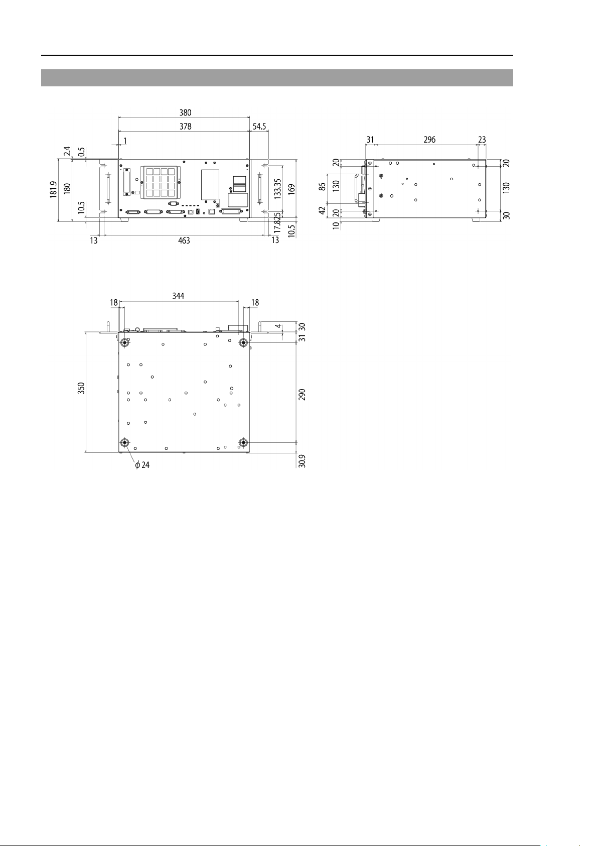
1.3 Outer Dimensions
[Unit : mm]
12 RC90 / RC90-B (EPSON RC+ 7.0) Rev.26
Page 27
Setup & Operation 2. Part Names and Functions
(3)
(18)
(11) (12) (13) (14) (15) (16) (6)
(4)
(1)
(10) (9)
(8)
(19)
(19)
(17)
(5)
(Left side)
(2)
(7)
The details of the Manipulator to be connected are recorded on
label indicates the
Manipulator model and Manipulator serial number.
MANIPULATOR
00002
LS3-401S
NOTE
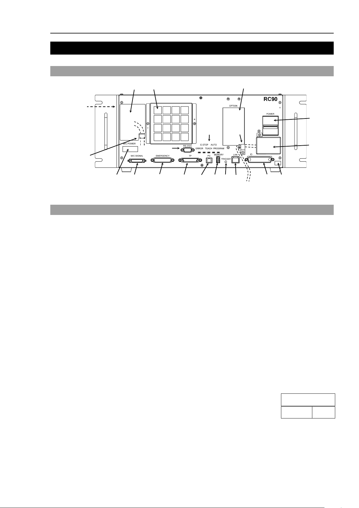
2. Part Names and Functions
2.1 Part Names
Illustration is RC90. Part names and functions of RC90 and RC90-B are the same.
2.2 Functions
(1) POWER switch
(2) AC IN
(3) LED
(4) Fan Filter
(5) Signature label
(6) Controller Number label
(7) Connection Check label
Turns ON or OFF the Controller.
The terminal block for 200VAC power input.
For details, refer to Setup & Operation 3.3.2 AC Power Cable.
The LED indicates current operation mode (ERROR, E-STOP, TEACH, AUTO, or
PROGRAM mode). For details, refer to Setup & Operation 2.3 LED.
A protective filter is installed in front of the fan to filter out dust.
Check the condition of the filter regularly and clean it when necessary. A dirty filter
may result in malfunction of the robot system due to temperature rise of the Controller.
The serial number of the Controller and other information are shown.
The serial number of the Controller is indicated.
the label as shown in the right. The
RC90 / RC90-B (EPSON RC+ 7.0) Rev.26 13
Page 28

Setup & Operation 2. Part Names and Functions
NOTE
(8) M/C POWER connector
A connector for the Manipulator power source.
Connect the dedicated power cable attached to the Manipulator.
(9) M/C SIGNAL connector
This connector is used for signals such as the manipulator’s motor position detector,
etc. Connect the Manipulator’s dedicated signal cable.
(10) EMERGENCY connector
This connector is used for input/output from/to Emergency Stop and Safety Door
switches. For details, refer to the Setup & Operation 9. EMERGENCY.
(11) TP port
Connects Teach Pendant TP1 (Option), TP2 (Option) and TP bypass plug. For details,
refer to Setup & Operation 8. TP Port.
Do not connect the following to the TP port of RC90 / RC90-B. Connecting to the
followings may result in malfunction of the device since the pin assignments are
different.
OPTIONAL DEVICE dummy plug
Operation Pendant OP500
Operator Pendant OP500RC
Jog Pad JP500
Teaching Pendant TP-3**
Operator Panel OP1
(12) Development PC connection port
This port connects the Controller and the Development PC using a USB cable.
Do not connect other devices except the Development PC.
For details, refer to Setup & Operation 5. Development PC Connection Port.
(13) Memory port
This port connects the common USB memory for Controller status storage function.
Do not connect other USB devices except the USB memory.
For details, refer to Setup & Operation 6. Memory Port.
(14) Trigger Switch
This switch is for Controller status storage function using the USB memory.
For details, refer to Setup & Operation 6. Memory Port.
(15) LAN (Ethernet communication) port
This port connects the Controller and the Development PC using an Ethernet cable.
100BASE-TX / 10BASE-T communication are available.
For details, refer to Setup & Operation 7. LAN (Ethernet communication) Port.
(16) I/O connector
This connector is used for input/output device. There are 24 inputs and 16 outputs.
For details, refer to Setup & Operation 11. I/O Connector.
(17) Standard RS-232C port
This port is used for the RS-232C communication with external devices.
For details, refer to
Setup & Operation 10. Standard RS-232C Port.
14 RC90 / RC90-B (EPSON RC+ 7.0) Rev.26
Page 29

Controller status
LED display
Execute Controller status
USB memory
TEACH, AUTO, PROGRAM turn ON
ERROR turns OFF even if an error occurs.
2.3 LED
Setup & Operation 2. Part Names and Functions
(18) Option slot
Option boards such as expansion I/O board, Fieldbus I/O board, RS-232C board, PG
board, Analog I/O board can be installed. Two slots are available.
For details, refer to Setup & Operation 13.Option Slots.
(19) Cable Clamp
This can be used to secure the M/C Power Cable and the AC Power cable.
(20) Battery (Mounted inside the controller)
This is a lithium battery for data backup.
Five LEDs are located on the front panel of the Controller.
LEDs (ERROR, E-S TO P, TEACH, AUTO, PROGRAM) turn ON according to the
controller status (error, Emergency Stop, TEACH mode, Auto mode, Program mode).
From turning ON the Controller to completing startup
Three LEDs (TEACH, AUTO, PROGRAM) blink.
After Controller Startup
storage function to the
Complete Controller status
storage to USB memory
Failure of Controller status
storage to USB memory
Error ERROR turns ON.
Warning ERROR blinks.
Emergency Stop E-STOP turns ON.
TEACH mode TEACH blinks.
Auto mode (AUTO mode) AUTO blinks.
Program mode (AUTO mode) PROGRAM blinks.
Recovery mode ERROR, TEACH, PROGRAM turn ON.
TEACH, AUTO, PROGRAM blink.
(for 2 seconds).
ERROR, TEACH, AUTO, PROGRAM turn ON
(for 2 seconds).
AC power supply drop TEACH, AUTO turn ON.
RC90 / RC90-B (EPSON RC+ 7.0) Rev.26 15
Test mode TEACH turns ON.
Page 30

Setup & Operation 2. Part Names and Functions
2.4 Safety Features
The robot control system supports safety features described below. However, it is
recommended to strictly follow the proper usage of the robot system by thoroughly reading
the attached manuals before using the system. Failure to read and understand the proper
usage of the safety functions is highly dangerous.
Among the following safety features, the Emergency Stop Switch and Safety Door Input are
particularly important. Make sure that these and other features function properly before
operating the robot system.
For details, refer to the Setup & Operation 9. EMERGENCY.
Emergency Stop Switch
The EMERGENCY connector on the Controller has expansion Emergency Stop input
terminals used for connecting the Emergency Stop switches.
Pressing any Emergency Stop switch can shut off the motor power immediately and the
robot system will enter the Emergency Stop condition.
Safety Door Input
In order to activate this feature, make sure that the Safety Door Input switch is connected to
the EMERGENCY connector at the Controller.
When the safety door is opened, normally the Manipulator immediately stops the current
operation, and the status of Manipulator power is operation-prohibited until the safety door
is closed and the latched condition is released. In order to execute the Manipulator
operation while the safety door is open, you must change the mode selector key switch on
the Teach Pendant to the “Teach” mode. Manipulator operation is available only when the
enable switch is on. In this case, the Manipulator is operated in low power status.
Low Power Mode
The motor power is reduced in this mode.
Executing a power status change instruction will change to the restricted (low power) status
regardless of conditions of the safety door or operation mode. The restricted (low power)
status ensures the safety of the operator and reduces the possibility of peripheral equipment
destruction or damage caused by careless operation.
Dynamic Brake
The dynamic brake circuit includes relays that short the motor armatures. The dynamic
brake circuit is activated when there is an Emergency Stop input or when any of the
following errors is detected: encoder cable disconnection, motor overload, irregular motor
torque, motor speed error, servo error (positioning or speed overflow), irregular CPU,
memory check-sum error and overheat condition inside the Motor Driver Module.
Motor Overload Detection
The dynamic brake circuit is activated when the system detects that the load on the motor
has exceeded its capacity.
Irregular Motor Torque (out-of-control manipulator) Detection
The dynamic brake circuit is activated when irregularity with motor torque (motor output)
is detected (in which case the Manipulator is out of control).
16 RC90 / RC90-B (EPSON RC+ 7.0) Rev.26
Page 31

Setup & Operation 2. Part Names and Functions
Motor Speed Error Detection
The dynamic brake circuit is activated when the system detects that the motor is running at
incorrect speed.
Positioning Overflow –Servo Error- Detection
The dynamic brake circuit is activated when the system detects that the difference between
the Manipulator’s actual position and commanded position exceeds the margin of error
allowed.
Speed Overflow –Servo Error- Detection
The dynamic brake circuit is activated when the Manipulator’s actual speed is detected to
mark an overflow (the actual speed is outside the nominal range) error.
CPU Irregularity Detection
Irregularity of CPU that controls the motor is detected by the watchdog timer. The system
CPU and the motor controlling CPU inside the Controller are also designed to constantly
check each other for any discrepancies. If a discrepancy is detected, the dynamic brake
circuit is activated.
Memory Check-sum Error Detection
The dynamic brake circuit is activated when a memory check-sum error is detected.
Overheat Detection at the Motor Driver Module
The dynamic brake circuit is activated when the temperature of the power device inside the
Motor Driver module is above the nominal limit.
Relay Deposition Detection
The dynamic brake circuit is activated when relay deposition, junction error, or open fault
is detected.
Over-Voltage Detection
The dynamic brake circuit is activated when the voltage of the Controller is above the
normal limit.
AC Power Supply Voltage Drop Detection
The dynamic brake circuit is activated when the drop of the power supply voltage is detected.
Temperature Anomaly Detection
The temperature anomaly is detected.
Fan Malfunction Detection
Malfunction of the fan rotation speed is detected.
RC90 / RC90-B (EPSON RC+ 7.0) Rev.26 17
Page 32

Setup & Operation 3. Installation
The Manipulator and the Controller must be used within the environmental
conditions described in their manuals. This product has been designed and
manufactured strictly for use in a normal indoor environment
in the environment that exc
of the
Item
Condition
Use a base table that is at least 100 mm off the floor.
3. Installation
3.1 Unpacking
TP/OP Bypass Plug 1 unit
EMERGENCY Port Connector 1 set
I/O Connector 1 set
Rack-Mount Plate 1 set
3.2 Environmental Requirements
■
WARNING
eeds the conditions may not only shorten the life cycle
product but also cause serious safety problems.
. Using the product
3.2.1 Environment
In order to optimize the robot system’s performance for safety, the Controller must be placed
in an environment that satisfies the following conditions:
- The Controller is not designed for clean-room specification. If it must be installed in a
clean room, be sure to install it in a proper enclosure with adequate ventilation and cooling.
- Install Controller in a location that allows easy connection / disconnection of cables.
Ambient temperature
Ambient relative humidity 20% to 80% (with no condensation)
Fast transient burst noise 2 kV or less (Power supply wire)
Electrostatic noise 4 kV or less
Base table
5 to 40 °C (with minimal variation)
1 kV or less (Signal wire)
Placing the Controller directly on the floor could allow
dust penetration leading to malfunction.
If the Controller must be used in an environment that does not fulfill the conditions
mentioned above, take adequate countermeasures. For example, the Controller may be
enclosed in a cabinet with adequate ventilation and cooling.
- Install indoors only.
- Place in a well-ventilated area.
- Keep away from direct sunlight and radiation heat.
- Keep away from dust, oily mist, oil, salinity, metal powder or other contaminants.
- Keep away from water.
- Keep away from shocks or vibrations.
- Keep away from sources of electronic noise
- Keep away from strong electric or magnetic fields.
18 RC90 / RC90-B (EPSON RC+ 7.0) Rev.26
Page 33

Setup & Operation 3. Installation
* The rubber foot needs to be replaced.
* Rack-mount plate is required.
133.35 mm
463 mm
50 mm
50 mm
100 mm
Excluding the installation
side such as base table
Air flow of the Controller Fan
100 mm
200 mm
NOTE
3.2.2 Installation
Install the controller on a flat surface such as wall, floor, and controller box in the direction
shown from (A) to (C).
(A) Flat Mounting
(B) Upright Mounting (C) Rack Mounting
For installing the Controller to the Controller box or the base table, process screw holes as
follows.
Ensure the draft around the in/out and prevent the other equipment, walls and install the
Controller by keeping the distance as follows for maintenance.
RC90 / RC90-B (EPSON RC+ 7.0) Rev.26 19
- Hot air with higher temperature than the ambient temperature (about 10 °C) comes out
from the Controller. Make sure that heat sensitive devices are not placed near the outlet.
- Arrange the cables in front of the Controller so that you can pull the Controller forward.
Page 34

Setup & Operation 3. Installation
Phase
Single phase
For approximate power consumption of each model, refer to
LS3 : 1.0 kVA
LS6 : 1.1 kVA
LS20 : 2.4 kVA
LS3-B: 1.0 kVA
LS6-B : 1.1 kVA
LS20-B : 2.4 kVA
LS10-B : 1.8 kVA
3.3 Power Supply
3.3.1 Specifications
Ensure that the available power meets following specifications.
Item Specification
Voltage 200 to 240 VAC
Frequency 50/60 Hz
Momentary Power
Interrupt
Rated Capacity Max. 2.5 kVA
Input voltage should be with in ±10 % of the rated voltage.
10 ms or less
Actual power consumption depends on the model, motion, and
load of the Manipulator.
the following values
Peak Current When power is turned ON : approximately 70 A (2 ms.)
Leakage Current Max. 10 mA
Ground Resistance
Install an earth leakage circuit breaker or a circuit breaker in the AC power cable line at 15
A or less rated electric current. Both should be a two-pole disconnect type. If you install
an earth leakage circuit breaker, make sure to use an inverter type that does not operate by
induction of a 10 kHz or more leakage current. If you install a circuit breaker, please select
one that will handle the above mentioned “peak current”.
The power receptacle shall be installed near the equipment and shall be easily accessible.
Refer to the Manipulator manual for rated capacity of the
Manipulator motor.
When motor is ON : approximately 50 A (2 ms.)
100 Ω or less
20 RC90 / RC90-B (EPSON RC+ 7.0) Rev.26
Page 35

Setup & Operation 3. Installation
Make sure that
B
terminal of the factory power supply.
at all times to avoid the risk of electric shock.
Always use a power plug
for power connecting cable.
Never connect the Controller directly to the factory power supply.
Select the plug
which conform safety standards for
nations.
Ground wire
Green / Yellow
3.3.2 AC Power Cable
■
■
e sure to connect the earth wire (green/yellow) of the AC power cable to the earth
WARNING
■
■
AC power wire (2 cables)
Cable length 3 m
Terminal M4 round solderless terminal
operations are done by a qualified personal.
The equipment must be grounded properly
or a disconnecting device
or a disconnecting device
Item Specification
Black, Black
or Black, White
RC90 / RC90-B (EPSON RC+ 7.0) Rev.26 21
Page 36

Setup & Operation 3. Installation
(1)
Mount the M/C Power Cable as shown
e picture and
form the cables.
(2)
Set the M/C Power Cable in the clamp for the M/C Power
Cable.
(3)
Mount the cover for the M/C Power
(4)
Secure the cover with the screw.
3.3.3 M/C Power Cable
in th
Connector.
22 RC90 / RC90-B (EPSON RC+ 7.0) Rev.26
Page 37

Make sure that the power to the Control
disconnected
Connecting or
disconnecting
result in electric shock and malfunction of the Controller.
Be sure to connect the cables properly. Do not
cables. (Do not put heavy objects on the cables. Do not bend or pull the cables
forcibly.) The unnecessary strain on the cables may result in damage to the
cables, disconnection, and/or contact failure. Damaged cables, d
contact failure is extremely hazardous and may result in electric shock and/or
improper function of the system.
The serial number of the Manipulator that should be connected is indicated on the
Connection Check Label on the Controller. Connect the Controller and the
Manipulator correctly. Improper connection between the Controller and the
Manipulator may cause not only improper function of the robot system but also
safety problems.
Before connecting the connector, make sure
the pins are not bent.
Connecting with
of the robot system.
3.4 Cable Connection
Setup & Operation 3. Installation
■
■
WARNING
■
CAUTION
■
ler is turned OFF and the power plug is
before connecting or disconnecting any cables.
any cables with the power ON is extremely hazardous and may
allow unnecessary strain on the
isconnection, or
that
the pins bent may damage the connector and result in malfunction
RC90 / RC90-B (EPSON RC+ 7.0) Rev.26 23
Page 38

Setup & Operation 3. Installation
Manipulator
(6) USB Memory
PC for Development
Input/Output Device
Connect by (5) or (7)
*1
*1
Controller
(1) AC Power Terminal Block
(2) M/C Power Connector
(3) M/C Signal Connector
(4) EMERGENCY Connector
(5) Development PC Connection Port
200VAC-240VAC
(7) LAN (Ethernet Communication)
(8) I/O Connector
(9) TP Connector
(10) Standard RS-232C Connector
Emergency Stop
Safety Door, etc.
Teach
Pendant
Option
FieldBus I/O
Expansion I/O
RS-232C
PG board
Analog I/O
EUROMAP67
Detachable connector
Cable attached at shipping
Cable prepared by users
(1)
AC Power terminal block
(2)
M/C Power cable
.
(3)
M/C Signal cable
(4)
EMERGENCY
3.4.1 Typical Cable Connection
*1: Only LS-B series is detachable.
Terminal block for 200VAC power input to the Controller.
The cable with 20-pin connector on the Controller side.
Connect the Manipulator and the M/C POWER connector on the Controller
Insert the connectors until you hear a “click”.
The cable with 36-pin connector on the Controller side.
Connect the Manipulator and the M/C SIGNAL connector on the Controller.
The EMERGENCY connector has inputs to connect the Emergency Stop switch
and the Safety Door switch. For safety reasons, connect proper switches for these
input devices.
For details, refer to the Setup & Operation 9. EMERGENCY.
24 RC90 / RC90-B (EPSON RC+ 7.0) Rev.26
Page 39

Setup & Operation 3. Installation
(5)
PC for development
(6)
USB memory
(7)
LAN (EtherNet Communication)
(8)
I/O connector
(9)
TP cable
(10)
Standard RS-232C port
Connect the PC for development.
For details, refer to the Setup & Operation 5. Development PC Port.
Connect the USB memory.
For details, refer to the Setup & Operation 6. Memory Port.
Connect the EtherNet cable.
For details, refer to the Setup & Operation 7. LAN (Ethernet Communication) Port.
This connector is used for input/output devices of the user.
When there are input/output devices, use this connector.
There are I/O cable (option) and terminal block (option) for the I/O connector.
For details, refer to the Setup & Operation 11. I/O Connector.
Connect the option Teach Pendant.
For details, refer to the Setup & Operation 8.TP Port.
This port is used for the RS-232C communication with external devices.
For details, refer to Setup & Operation 10. Standard RS-232C Port.
RC90 / RC90-B (EPSON RC+ 7.0) Rev.26 25
Page 40

Setup & Operation 3. Installation
Make sure that the power to the Control
turned OFF before connecting or
disconnecting any cables.
any cables with the
power ON
of
Be sure to connect the cables
cables. (Do not put heavy objects on the cables. Do not bend or pull the cables
forcibly.) The unnecessary strain on the cables may result in damage to the
cables, disconnection, and/or contact failure.
contact failure is extremely hazardous and may result in electric shock and/or
improper function of the system.
on the Controller. Connect the Controller and the
Improper connection between the Controller and the
When connecting the Manipulator to the Controller, make sure that the serial
numbers on each equipment match. Improper connection between the
Manipulator and Controller may not only cause improper function of the robot
3.4.2 Connecting Manipulator to Controller
Connect the Manipulator to the Controller by using the Power cable and the Signal cable.
■
is extremely hazardous and may result in electric shock and malfunction
the Controller.
■
WARNING
■ The serial number of the Manipulator that should be connected is indicated on the
Connection Check Label
Manipulator correctly.
Manipulator may cause not only improper function of the robot system but also
safety problems.
CAUTION
■
system but also serious safety problems. The connection method varies with the
Controller used. For details on the connection, refer to the Controller manual.
ler is
Connecting or disconnecting
properly. Do not allow unnecessary strain on the
Damaged cables, disconnection, or
26 RC90 / RC90-B (EPSON RC+ 7.0) Rev.26
Page 41

Setup & Operation 3. Installation
LS3 series Manipulator
(Figure: LS3-401S)
RC90 Controller
M/C Power Cable
M/C Signal Cable
NOTE
The configuration data for the Manipulator and Manipulator model are stored in the
Controller. Therefore the Controller should be connected to the Manipulator whose serial
number is specified in the Connection Check label attached on the front of the Controller.
The Manipulator’s serial number is indicated on the signature label of the Manipulator.
RC90 / RC90-B (EPSON RC+ 7.0) Rev.26 27
Page 42

Setup & Operation 3. Installation
preferable example is shown in the right figure.
AC Line duct
DC line duct
As far as
possible
3.5 Noise Countermeasures
To minimize electrical noise conditions, the following items must be observed in the
system’s cable wiring:
To minimize electrical noise condition, be sure of followings for wiring.
- The earth wire of the power supply should be grounded. (Ground resistance: 100 Ω or
less) It is important to ground the frame of Controller not only for prevention from
electric shock, but also for reducing the influence of electric noise around the Controller.
Therefore, be sure to connect the earth wire (yellow/green) of the Controller’s power
cable to the ground terminal of the factory power supply. For details about the plug
and AC power cable, refer to the Setup & Operation 3.3 Power Supply.
- Do not tap power from a power line that connects to any equipment which may cause
noise.
- When you tap power for the Controller and the single-phase AC motor from the same
power line, change the phase of one or the other. Ensure that they will not be the same
phase.
- Use a twisted pair motor power line.
- Do not run AC power lines and DC power lines in
the same wiring duct, and separate them as far as
possible. For example, separate the AC motor
power line and the Controller power line as far as
possible from the sensor or valve I/O lines; and do
not bundle both sets of wiring with the same cable
tie. If more than one duct/cable must cross each
other, they should cross perpendicularly. The
- Wire as short as possible to the I/O connector and EMERGENCY connector. Use a
shielded cable and clamp the shield to the attached connector interior. Make sure to
keep away from the peripheral noise source as far as possible.
- Make sure that the induction elements used to connect to the Controller’s I/O (such as
relays and solenoid valves) are noise suppression parts. If an induction element without
protection against noise is used, make sure to connect a noise suppression part such as a
diode located at the induction element in parallel with it. In selecting noise suppression
parts, make sure that they can handle the voltage and current incurred by the induction
load.
- To start and change revolutions of the conveyer’s (or the like’s) AC motor (ex: an
induction motor or three-phase induction motor) regularly or abruptly, make sure to
install a spark suppressor between the wires. The spark suppressor is more effective
when placed closer to the motor.
- As they are easily influenced by noise, keep cable such as USB, Ethernet, RS-232C, or
fieldbus away from peripheral noise sources.
28 RC90 / RC90-B (EPSON RC+ 7.0) Rev.26
Page 43

Setup & Operation 4. Operation Mode (TEACH/AUTO/TEST)
In this mode the Robot operates in Low power status.
This mode enables automatic operation (program execution) of the
This mode cannot operate the Robots or run programs with the Safety
Door open.
This is a low speed program verification function (T1: manual
task, multi-manipulator / single-manipulator at low speed.
The operating Robot stops by Quick Pause.
and turn on the latch
release input signal for AUTO mode.
mode.
[Test Mode] in [Jog & Teach] dialog of TEACH mode.
The mode will be changed to TEST
4. Operation Mode (TEACH/AUTO/TEST)
4.1 Overview
The Robot system has three operation modes.
TEACH mode This mode enables point data teaching and checking close to the Robot
using the Teach Pendant.
AUTO mode
Robot system for the manufacturing operation, and also programming,
debug, adjustment, and maintenance of the Robot system.
TEST mode
4.2 Switch Operation Mode
Change the operation mode using the mode selector key switch on the Teach Pendant.
TEACH mode Turn the mode selector key switch to “Teach” for TEACH mode.
AUTO mode Turn the mode selector key switch to “Auto”
TEST mode Turn the mode selector key switch to “Teach” for “TEACH”
This mode enables program verification while the Enable Switch is
held down and the safeguard is open.
deceleration mode) which is defined in Safety Standards.
This mode can operate the specified Function with multi-task / single-
Switching to TEACH mode pauses the program if it was running.
Push <F1> key-
RC90 / RC90-B (EPSON RC+ 7.0) Rev.26 29
Page 44

Setup & Operation 4. Operation Mode (TEACH/AUTO/TEST)
(2)
(5)
(3)
(4)
4.3 Program Mode (AUTO)
4.3.1 What is Program Mode (AUTO)?
Program mode is for programming, debug, adjustment, and maintenance of the Robot
system.
Follow the procedures below to switch to the Program mode.
4.3.2 Setup from EPSON RC+ 7.0
Switch the mode to Program mode from the EPSON RC+ 7.0.
(1) Select EPSON RC+ 7.0 menu-[Setup]-[System Configuration] to display the [System
Configuration] dialog.
(2) Select [Startup].
(3) Select [Start mode]-<Program> button.
(4) Click the <Apply> button.
(5) Click the <Close> button.
30 RC90 / RC90-B (EPSON RC+ 7.0) Rev.26
Page 45

(2)
(5)
(3)
(4)
NOTE
4.4 Auto Mode (AUTO)
4.4.1 What is Auto mode (AUTO)?
Auto mode (AUTO) is for automatic operation of the Robot system.
Procedures for switching to the Auto mode (AUTO) are the followings.
A : Set the start mode of the EPSON RC+ 7.0 to “Auto” and start the EPSON RC+ 7.0.
(Refer to Setup & Operation 4.4.2 Setup from EPSON RC+ 7.0.)
B : Offline the EPSON RC+ 7.0.
Execute and stop the program from the control device specified by the EPSON RC+ 7.0.
(Refer to Setup & Operation 4.4.3 Setup Control Device.)
4.4.2 Setup from EPSON RC+ 7.0
Switch the mode to Auto mode (AUTO) from the EPSON RC+ 7.0.
(1) Select EPSON RC+ 7.0 menu-[Setup]-[System Configuration] to display the [System
Configuration] dialog.
Setup & Operation 4. Operation Mode (TEACH/AUTO/TEST)
(2) Select [Startup].
(3) Select [Start Mode]-<Auto> button.
(4) Click the <Apply> button.
(5) Click the <Close> button.
RC90 / RC90-B (EPSON RC+ 7.0) Rev.26 31
Page 46

Setup & Operation 4. Operation Mode (TEACH/AUTO/TEST)
(2)
(5)
(3)
(4)
4.4.3 Setup from Control Device
Set the control device from EPSON RC+ 7.0.
(1) Select EPSON RC+ 7.0 menu-[Setup]-[System Configuration] to display the [System
Configuration] dialog.
(2) Select [Controller]-[Configuration].
(3) Select [Control Device] to select the control device from the following two types.
- PC
- Remote (I/O)
(4) Click the <Apply> button.
(5) Click the <Close> button.
32 RC90 / RC90-B (EPSON RC+ 7.0) Rev.26
Page 47

Setup & Operation 5. Development PC Connection Port
Development PC connection Port
NOTE
5. Development PC Connection Port
Development PC connection USB port (USB B series connector)
For other details of development PC and Controller connection, refer to EPSON RC+ 7.0
User’s Guide 5.12.1 PC to Controller Communications Command.
For RC90/RC90-B, be sure to install the EPSON RC+ 7.0 to the development PC first, then
connect the development PC and RC90/RC90-B with the USB cable.
If RC90/RC90-B and the development PC are connected without installing the EPSON RC+
7.0 to the development PC, [Add New Hardware Wizard] appears. If this wizard appears,
click the <Cancel> button.
5.1 About Development PC Connection Port
The development PC connection port supports the following USB types.
- USB2.0 HighSpeed/FullSpeed (Speed auto selection, or FullSpeed mode)
- USB1.1 FullSpeed
Interface Standard : USB specification Ver.2.0 compliant
Connect the Controller and development PC by a USB cable to develop the robot system or
set the Controller configuration with the EPSON RC+ 7.0 software installed in the
development PC.
Development PC connection port supports hot plug feature. Cables insert and remove
from the development PC and the Controller is available when the power is ON.
However, stop occurs when USB cable is removed from the Controller or the development
PC during connection.
(USB Ver.1.1 upward compatible)
RC90 / RC90-B (EPSON RC+ 7.0) Rev.26 33
Page 48

Setup & Operation 5. Development PC Connection Port
5.2 Precaution
When connecting the development PC and the Controller, make sure of the following:
- Connect the development PC and the Controller with a 5 m or less USB cable.
Do not use the USB hub or extension cable.
- Make sure that no other devices except the development PC are used for development
PC connection port.
- Use a PC and USB cable that supports USB2.0 HighSpeed mode to operate in USB2.0
HighSpeed mode.
- Do not pull or bend the cable strongly.
- Do not allow unnecessary strain on the cable.
- When the development PC and the Controller are connected, do not insert or remove
other USB devices from the development PC. Connection with the Controller may be
lost.
5.3 Software Setup and Connection Check
Connection of the development PC and the Controller is indicated.
(1) Make sure that software EPSON RC+ 7.0 (Ver.7.0.2 or later is recommended) is
installed to the Controller connected to the development PC.
(Install the software when it is not installed.
Installation or EPSON RC+ 7.0 User’s Guide.
Refer to Robot System Safety and
(2) Connect the development PC and the Controller using a USB cable.
(3) Turn ON the Controller.
(4) Start EPSON RC+ 7.0.
(5) Select the EPSON RC+ 7.0 menu-[Setup]-[PC to Controller Communications] to
display the [PC to Controller Communications] dialog.
(6) Select “No.1 USB” and click the <Connect> button.
34 RC90 / RC90-B (EPSON RC+ 7.0) Rev.26
Page 49

Setup & Operation 5. Development PC Connection Port
NOTE
(7) After the development PC and the Controller connection has completed, “Connected”
is displayed at [Connection status]. Make sure that “Connected” is displayed and
click the <Close> button to close the [PC to Controller Communications] dialog.
The connection between the development PC and the Controller is completed. Now the
robot system can be used from EPSON RC+ 7.0.
5.4 Disconnection of Development PC and Controller
Disconnection of the development PC and the Controller communication.
(1) Select the EPSON RC+ 7.0 menu-[Setup]-[PC to Controller Communications] to
display the [PC to Controller Communications] dialog.
(2) Click the <Disconnect> button.
Communication between the Controller and the development PC is disconnected and
the USB cable can be removed.
If the USB cable is removed when the Controller and the development PC are connected,
the Robot will stop. Be sure to click the <Disconnect> button in the [PC to Controller
Communications] dialog before USB cable is removed.
RC90 / RC90-B (EPSON RC+ 7.0) Rev.26 35
Page 50

Setup & Operation 6. Memory Port
■
Controller status storage function is available at any time and in any Controller
status after starting the Controller.
However, operations form the console including stop and pause are not
while executing this function.
Also,
EPSON
function when operating the robot.
6. Memory Port
Connect a commercial USB memory to the Controller memory port to use the Controller
status storage function to the USB memory.
6.1 What is Controller Status Storage Function?
This function saves various kinds of Controller data with one push to the USB memory.
Data saved in USB memory is loaded to EPSON RC+ 7.0 to get the status of the Controller
and the program simply and accurately.
The saved data can also be used for restoring the Controller.
6.2 Before Using Controller Status Storage Function
6.2.1 Precautions
CAUTION
this function influences the robot cycle time and the communication with
RC+ 7.0. Other than only when it is necessary, do not execute this
available
- Make sure that the USB port is used only for USB memory even though the port on the
Controller is a universal USB port.
- Insert the USB memory directly into the Controller memory port. Connection with
cables or hubs between the Controller and the USB memory is not assured.
- Make sure that the USB memory is inserted or removed slowly.
- Do not edit the saved files with an editor. Operation of the robot system after data
restoration to the Controller is not assured.
6.2.2 Adoptable USB Memory
Use USB memory that meets following conditions.
- USB2.0 supported
- Without security function
USB memory with password input function cannot be used.
- No installation of a driver or software is necessary for Windows 8, or Windows 10.
(For supported operating systems for the EPSON RC+ 7.0, refer to Setup & Operation
1.1 System Example.)
36 RC90 / RC90-B (EPSON RC+ 7.0) Rev.26
Page 51

6.3 Controller Status Storage Function
■
Controller status storage function is available at any time and in any Controller
status after starting the Controller.
However, operations form the console including stop and pause are not
while executing this function.
Also, this function
EPSON
function when operating the robot.
NOTE
6.3.1 Controller Status Storage with Trigger Button
CAUTION
influences the robot cycle time and the communication with
RC+ 7.0. Other than only when it is necessary, do not execute this
Use this procedure to save the status of the Controller to USB memory.
(1) Insert the USB memory into the memory port.
(2) Wait approximately 10 seconds for USB memory recognition.
(3) Press the trigger button on the Controller.
When the data transfer starts, the LED of
Wait until the LED status changes.
(The data transfer time varies according to the data size such as of the projects.)
Setup & Operation 6. Memory Port
available
TEACH, AUTO, and PROGRAM starts blinking.
(4) When the controller status storage is completed successfully, the LED of TEACH, AUTO,
and PROGRAM are turned ON for two seconds. Note that the LED of ERROR turns OFF
even in the error status.
If it ends in failure, the LED of ERROR, TEACH, AUTO, and PROGRAM are turned ON
for two seconds.
(5) Remove the USB memory from the Controller.
- USB memory with LED is recommended to check the status changes in procedure (2).
- When storage is executed during Motor ON status, it may fail to store the status.
Use another USB memory or execute the storage during Motor OFF status.
6.3.2 Load Data with EPSON RC+ 7.0
The following shows the procedure to read the data stored in the USB memory by EPSON
RC+ 7.0 and display the Controller status.
(1) Insert the USB memory into the PC with EPSON RC+ 7.0.
(2) Make sure that the following folder is indicated in the USB memory.
B_controller model_serial number_data status was saved
→ Example RC90 : B_RC90_12345_2013-10-29_092951
→ Example RC90-B : B_RC90-B_12345_2013-10-29_092951
(3) Copy the folder confirmed in procedure (2) to the “\EpsonRC70\Backup” folder.
RC90 / RC90-B (EPSON RC+ 7.0) Rev.26 37
Page 52

Setup & Operation 6. Memory Port
(4) Select the EPSON RC+ 7.0 menu-[Tools]-[Controller] to display the [Controller Tools]
dialog.
(5) Click the <View Controller Status…> button.
(6) [Browse For Folder] dialog appears. Select the folder copied in procedure (3) and click
the <OK> button.
(7) [Controller Status Viewer] dialog appears to confirm the Controller status.
For details, refer to View Controller Status in EPSON RC+ 7.0 User’s Guide 5.11.8
Controller Command (Tools Menu).
38 RC90 / RC90-B (EPSON RC+ 7.0) Rev.26
Page 53

6.3.3 Transfer with E-mail
File Name
Outline
for restore
parameter
CurrentStatus.txt
Save status
Saves program and I/O status.
ErrorHistory.csv
Error history
InitFileSrc.txt
Initial setting
Saves various settings of the Controller.
MCSys01.MCD
Robot setting
Saves information of connected robot.
information
Prg file is not included.
variables
information
VXDWORK.bin
When [Include project files when status exported] check box
the project file is stored. Includes program files.
NOTE
Follow this procedure to transfer the data by e-mail that was saved to the USB memory.
(1) Insert the USB memory to a PC that supports sending of e-mail.
(2) Make sure that the USB memory has following folders.
B_controller model_serial number_data status was saved
→ Example RC90 : B_RC90_12345_2013-10-29_092951
→ Example RC90-B : B_RC90-B_12345_2013-10-29_092951
(3) Send all the folders by e-mail.
- Delete files that do not relate to the project before transfer.
- This function is used to send the data to the system director and EPSON from the end
users for problem analysis.
6.4 Details of Data
The following data files are created by the Controller status storage function.
Setup & Operation 6. Memory Port
Backup.txt Information file
CurrentMnp01.PRM Robot
SrcmcStat.txt Hardware
File with information for Controller restore.
Saves information such as ToolSet.
Saves installation information of hardware.
ProjectName.obj OBJ file Result of project build.
GlobalPreserves.dat *1 Global Preserve
WorkQueues.dat WorkQue
MCSRAM.bin
MCSYSTEMIO.bin
MCTABLE.bin
MDATA.bin
Inner
information
of Robot
operation
Saves values of Global Preserve variables.
Saves information of Queues information of the WorkQue.
SERVOSRAM.bin
All files related to
Project
project except
ProjectName.obj *2
*1 When the Controller firmware version is Ver.1.0.*.*, GlobalPreserves.dat is not stored.
*2 Storage of “All files related to project except ProjectName.obj” can be specified by a setting.
RC90 / RC90-B (EPSON RC+ 7.0) Rev.26 39
is checked in EPSON RC+ 7.0 menu-[Setup]-
[System Configuration]-[Controller]-[Preference],
Page 54

Setup & Operation 7. LAN (Ethernet Communication) Port
Private Address List
NOTE
7. LAN (Ethernet Communication) Port
- Refer to EPSON RC+ 7.0 User’s Guide 5.12.1 [PC to Controller Communications]
Command (Setup Menu)
connection.
- For Ethernet (TCP/IP) communication with robot application software, refer to EPSON
RC+ 7.0 Online Help or User’s Guide 14. TCP/IP Communications.
7.1 About the LAN (Ethernet Communication) Port
Ethernet communication port supports 100BASE-TX / 10 BASE-T.
This port is used for two different purposes.
Connection with development PC
LAN (Ethernet communication) port is used for connection of the Controller and the
development PC.
Equivalent operation is available to connect between the Controller and the development
PC with the development PC connection port.
(Refer to Setup & Operation 5. Development PC Connection Port)
for other details for the development PC and Controller
Connection with other Controller or PC
7.2 IP Address
From the following firmware version password authentication is required when connecting
Controllers and PCs to a global accessible network.
F/W : Ver.7.4.8.x
Our robot system is provided on the assumption that customers use it in the closed local area
networks. We considered the setting of the global IP address is access to the Internet and
changed the specification to perform password authentication in order to secure the
connections.
Password authentication is not performed in case of USB connections.
Be sure to use the following private IP addresses.
The LAN (Ethernet communication) port can be used as an Ethernet (TCP/IP)
communication port to communicate between multiple controllers from robot application
software.
10.0.0.1 to 10.255.255.254
172.16.0.1 to 172.31.255.254
192.168.0.1 to 192.168.255.254
The following is the configuration of the controller at delivery.
IP Address : 192.168.0.1
IP Mask : 255.255.255.0
IP Gateway : 0.0.0.0
40 RC90 / RC90-B (EPSON RC+ 7.0) Rev.26
Page 55

Setup & Operation 7. LAN (Ethernet Communication) Port
NOTE
7.3 Changing Controller IP Address
In this section, the procedure to change the Controller IP address when connecting
Controller development PC connection port and the development PC by the USB cable is
indicated.
(1) For connection between the development PC and the Controller, refer to Setup &
Operation
(2) Select the EPSON RC+ 7.0 menu-[Setup]-[Controller] to display the following dialog.
5. Development PC Connection Port.
(3) Select [Controller]-[Configuration].
(4) Enter the proper IP address and subnet mask and click the <Apply> button.
(5) Click the <Close> button. The Controller reboots automatically.
IP address configuration is completed and the Controller reboot dialog disappears.
When the Controller and the development PC are connected via the Ethernet, the Controller
IP address can also be changed. However, Controller and the development PC do not
connect automatically after rebooting the Controller at Ethernet connection.
RC90 / RC90-B (EPSON RC+ 7.0) Rev.26 41
Page 56

Setup & Operation 7. LAN (Ethernet Communication) Port
7.4 Connection of Development PC and Controller with Ethernet
Connection between the development PC and the Controller is shown below.
(1) Connect the development PC and the Controller using the Ethernet cable.
(2) Turn on the Controller.
(3) Start EPSON RC+ 7.0.
(4) Display the [PC to Controller Communication] dialog from [Setup] in EPSON RC+ 7.0
menu.
(5) Click the <Add> button.
(6) Connection “No.2” is added. Set the following and click the <Apply> button.
Name : Valid value to identify the controller to connect
IP Address : IP address for Controller to connect
(7) [Name] and [IP Address] specified in procedure (6) is displayed.
42 RC90 / RC90-B (EPSON RC+ 7.0) Rev.26
Page 57

Setup & Operation 7. LAN (Ethernet Communication) Port
NOTE
(8) Make sure that “No.2” is selected, and click the <Connect> button.
(9) After the development PC and Controller connection is completed, “Connected” is
displayed in the [Connection status:]. Make sure that “Connected” is displayed and
click the <Close> button to close the [PC to Controller Communications] dialog.
Connection between the development PC and the Controller is complete. Now the robot
system can be used via an Ethernet connection from EPSON RC+ 7.0.
7.5 Disconnection of Development PC and Controller with Ethernet
Disconnection of the development PC and the Controller is shown below.
(1) Display [PC-Controller Connection] dialog from [Setup] in EPSON RC+ 7.0 menu.
(2) Click the <Disconnect> button.
Communication between the Controller and the development PC is disconnected and
the Ethernet cable can be removed.
If the Ethernet cable is removed when the Controller and the development PC is connected,
Emergency Stop occurs and the Robot stops. Be sure to click the <Disconnect> button in
the [PC to Controller Communications] dialog before the Ethernet cable is removed.
RC90 / RC90-B (EPSON RC+ 7.0) Rev.26 43
Page 58

Setup & Operation 8. TP Port
NOTE
NOTE
8. TP Port
8.1 What is the TP Port?
The TP port connects the Teach Pendant to the Controller. You can connect the Teach
Pendant.
When nothing is connected to the TP port, Emergency Stop status occurs in the Controller.
When the Teach Pendant is not connected, connect the TP bypass plug.
Do not connect the following devices to the TP port of RC90/RC90-B. Connecting these
devices may result in malfunction of the device since the pin assignments are different.
OPTIONAL DEVICE dummy plug
Operation Pendant OP500
Operator Pendant OP500RC
Jog Pad JP500
Teaching Pendant TP-3**
Operator Panel OP1
8.2 Teach Pendant Connection
A cable for connection to the RC90/RC90-B Controller is attached to the Teach Pendant.
Connect this cable connector to the TP port.
Communication is set automatically. Enable the Teach Pendant by one of the following
procedures.
- Insert the Teach Pendant connector to the Controller and turn ON the Controller.
- Insert the Teach Pendant connector while the Controller is turned ON.
- Teach Pendant connection and disconnection from the Controller are allowed when the
Controller power is ON.
- When the Teach Pendant connector is removed from the Controller with the mode
selector key switch of the Teach Pendant in the “Teach” position, the operation mode
will remain in the TEACH mode. The operation mode cannot be switched to AUTO
mode. Be sure to remove the Teach Pendant after switching the operation mode to
“Auto” mode.
For details, refer to manual
Robot Contoroller RC700/RC90 Option Teach Pendant TP1.
Robot Contoroller RC700/RC90 Option Teach Pendant TP2.
44 RC90 / RC90-B (EPSON RC+ 7.0) Rev.26
Page 59

9. EMERGENCY
■
Before connecting the connector, make sure that the pins are not bent.
Connecting with
of
EMERGENCY Connector
Connector
Standard
NOTE
The details of safety requirements for this section are described in EPSON RC+ 7.0 2. Safety.
Please refer to them to keep the robot system safe.
Connect a safeguard switch or Emergency Stop switch to the Controller EMERGENCY
connector for safety.
When nothing is connected to the EMERGENCY connector, the robot system does not
operate normally.
Setup & Operation 9. EMERGENCY
the pins bent may damage the connector and result in malfunction
WARNING
the robot system.
9.1 Safety Door Switch and Latch Release Switch
The EMERGENCY connector has input terminals for the Safety Door switch and the
Emergency Stop switch. Be sure to use these input terminals to keep the system safe.
EMERGENCY connector
(Controller side)
* The E-STOP BOX, EMERGENCY connector cable, terminal block, and EMERGENCY
connector kit are offered as options.
D-sub 25 male pin
Screwlock #4 - 40
RC90 / RC90-B (EPSON RC+ 7.0) Rev.26 45
Page 60

Setup & Operation 9. EMERGENCY
■
The interlock of the Safety Door must be functioning when the
operated.
be turned ON/OFF (e.g. The tape is put around the switch.). Operating the robot
system when the s
cause
function
NOTE
9.1.1 Safety Door Switch
Do not operate the system under the condition that the switch cannot
robot system is
WARNING
witch is not functioning properly is extremely hazardous and may
serious safety problems as the Safety Door input cannot fulfill its intended
.
In order to maintain a safe working zone, a safeguard must be erected around the
Manipulator. The safeguard must have an interlock switch at the entrance to the working
zone. The Safety Door that is described in this manual is one of the safeguards and an
interlock of the Safety Door is called a Safety Door switch. Connect the Safety Door
switch to the Safety Door input terminal on the EMERGENCY connector.
The Safety Door switch has safety features such as temporary hold-up of the program or the
operation-prohibited status that are activated whenever the Safety Door is opened.
Observe the followings in designing the Safety Door switch and the Safety Door.
- For the Safety Door switch, select a switch that opens as the Safety Door opens, and not
by the spring of the switch itself.
- The signal from the Safety Door (Safety Door input) is designed to input to two
redundant signals. If the signals at the two inputs differ by two seconds or more, the
system recognizes it to be a critical error. Therefore, make sure that the Safety Door
switch has two separate redundant circuits and that each connects to the specified pins
at the EMERGENCY connector on the Controller.
- The Safety Door must be designed and installed so that it does not close accidentally.
9.1.2 Latch Release Switch
The controller software latches these conditions:
- The safety door is open.
- The operation mode is set to “TEACH”.
The EMERGENCY connector has an input terminal for a latch release switch that cancels
the latched conditions.
Open : The latch release switch latches conditions that the safety door is open or the
operation mode is “TEACH”.
Closed : The latch release switch releases the latched conditions.
When the latched TEACH mode is released while the safety door is open, the status of
Manipulator power is operation-prohibited because the safety door is open at that time.
To execute a Manipulator operation, close the safety door again, and then close the latch
release input.
46 RC90 / RC90-B (EPSON RC+ 7.0) Rev.26
Page 61

9.1.3 Checking Latch Release Switch Operation
NOTE
After connecting the safety door switch and latch release switch to the EMERGENCY
connector, be sure to check the switch operation for safety by following the procedures
described below before operating the Manipulator.
(1) Turn ON the Controller while the safety door is open in order to boot the controller
software.
(2) Make sure that “Safety” is displayed on the main window status bar.
(3) Close the safety door, and turn ON the switch connecting to the latch release input.
Make sure that the “Safety” is dimmed on the status bar.
The information that the safety door is open can be latched by software based on the latch
release input condition. To cancel the condition, close the safety door, and then close the
safety door latch release input.
Open : The latch release switch latches the condition that the safety door is open.
Closed : The latch release switch does not latch the condition that the safety door is open.
The latch release input also functions to acknowledge the change of to TEACH mode.
In order to change the latched condition of TEACH mode, turn the mode selector key switch
on the Teach Pendant to “Auto”. Then, close the latch release input.
Setup & Operation 9. EMERGENCY
RC90 / RC90-B (EPSON RC+ 7.0) Rev.26 47
Page 62

Setup & Operation 9. EMERGENCY
NOTE
9.2 Emergency Stop Switch Connection
9.2.1 Emergency Stop Switch
If it is desired to add an external Emergency Stop switch(es) in addition to the Emergency
Stop on the Teach Pendant and Operator Panel, be sure to connect such Emergency Stop
switch(es) to the Emergency Stop input terminal on the EMERGENCY connector.
The Emergency Stop switch connected must comply with the following:
- It must be a push button switch that is “normally closed”.
- A button that does not automatically return or resume.
- The button must be mushroom-shaped and red.
- The button must have a double contact that is “normally closed”.
The signal from the Emergency Stop switch is designed to use two redundant circuits.
If the signals at the two circuits differ by two seconds or more, the system recognizes it as
a critical error. Therefore, make sure that the Emergency Stop switch has double
contacts and that each circuit connects to the specified pins on the EMERGENCY
connector at the Controller. Refer to the Setup & Operation 9.4 Circuit Diagrams.
9.2.2 Checking Emergency Stop Switch Operation
Once the Emergency Stop switch is connected to the EMERGENCY connector, continue
the following procedure to make sure that the switch functions properly. For the safety
of the operator, the Manipulator must not be powered ON until the following test is
completed.
(1) Turn ON the Controller to boot the controller software while pressing the Emergency
Stop switch.
(2) Make sure that E-STOP LED of the controller is lighting.
(3) Make sure that “EStop” is displayed on the status bar on the main window.
(4) Release the Emergency Stop Switch.
(5) Execute the RESET command.
(6) Make sure that E-STOP LED is turned OFF and that “EStop” is dimmed on the main
window status bar.
9.2.3 Recovery from Emergency Stop
To recover from the emergency stop condition, follow the procedure of safety check as
required by the system.
After safety check, the operations below are required to recover from the emergency stop
condition.
- Release the Emergency Stop Switch
- Execute the RESET command
48 RC90 / RC90-B (EPSON RC+ 7.0) Rev.26
Page 63

Setup & Operation 9. EMERGENCY
-
Emergency Stop switch output rated load
+30 V 0.3 A or under
1-2, 14-15 pin
■
The 24 V output is for emergency stop. Do not use it for other purposes. Doing
so may result in system malfunction.
■
Do not apply reverse voltage to the Emergency Stop circuit. Doing so may result
in system malfunction.
NOTE
9.3 Pin Assignments
The EMERGENCY connector pin assignments are as follows:
Pin No. Signal Function Pin No. Signal Function
1 ESW11 Emergency Stop switch contact (1) *3 14 ESW21 Emergency Stop switch contact (2) *3
2 ESW12 Emergency Stop switch contact (1) *3 15 ESW22 Emergency Stop switch contact (2) *3
3 ESTOP1+ Emergency Stop circuit 1 (+) *4 16 ESTOP2+ Emergency Stop circuit 2 (+) *4
4
ESTOP1−
5 Not Used *1 18 SDLATCH1 Safety Door Latch Release
6 Not Used *1 19 SDLATCH2 Safety Door Latch Release
7 SD11 Safety Door input (1) *2 20 SD21 Safety Door input (2) *2
8 SD12 Safety Door input (1) *2 21 SD22 Safety Door input (2) *2
9 24V +24V output 22 24V +24V output
10 24V +24V output 23 24V +24V output
11 24VGND +24V GND output 24 24VGND +24V GND output
12 24VGND +24V GND output 25 24VGND +24V GND output
13 Not Used
Emergency Stop circuit 1 (
) *4
17
ESTOP2−
Emergency Stop circuit 2 (-) *4
*1 Do not connect anything to these pins.
*2 A critical error occurs if the input values from the Safety Door 1 and Safety Door 2 are
different for two or more seconds. They must be connected to the same switch with
two sets of contacts.
*3 A critical error occurs if the input values from the Emergency Stop switch contact 1
and Emergency Stop switch contact 2 are different for two or more seconds. They
must be connected the same switch with two sets of contacts.
*4 Do not apply reverse voltage to the Emergency Stop circuit.
Emergency Stop rated input voltage range
Emergency Stop rated input current
Safety Door rated input voltage range
Safety Door rated input current
Latch Release rated input voltage range
Latch Release rated input current
The total electrical resistance of the Emergency Stop switches and their circuit should be
1 Ω or less.
+24 V ±10%
37.5 mA ±10% /+24 V input
+24 V ±10%
10 mA/+24 V input
+24 V ±10%
10 mA/+24 V input
3-4, 16-17 pin
7-8, 20-21 pin
18-19 pin
CAUTION
RC90 / RC90-B (EPSON RC+ 7.0) Rev.26 49
Page 64

+24V
+5V
Safety Door input 1
External
+24V
Safety Door input 2
Latch release input
Latch release input Close :Latch off
Open :Latch on
Main Circuit
Control
AC Input
Emergency
Stop switch of
an Operation
Unit (TP)
External +24V
GND
External Emergency
Stop switches
Motor Driver
+
−
Controller
9
10
22
23
1
2
14
15
3
16
4
17
11
12
24
25
7
8
20
21
18
19
+
Emergency
Stop detection
NOTE:+24V GND
+ 5V GND
ESTOP1+
ESTOP2+
ESTOP1−
ESTOP2−
Be careful of
the direction
of voltage
application
Setup & Operation 9. EMERGENCY
9.4 Circuit Diagrams
9.4.1 Example 1: External emergency stop switch typical application
50 RC90 / RC90-B (EPSON RC+ 7.0) Rev.26
Page 65

Setup & Operation 9. EMERGENCY
+24V
+5V
Safety Door input 1
External
+24V
Safety Door input 2
Latch Release input
Latch release input Close :Latch off
Open :Latch on
AC Input
Emergency
Stop switch of
an Operation
Unit (TP)
External
+24V
GND
9
10
22
23
1
2
14
15
3
16
4
17
11
12
24
25
7
8
20
21
18
19
External +24V
Motor Drive
+
−
Controller
+
NOTE:+24V GND
+ 5V GND
External
+24V GND
External
+24V
Fuse
External
+24V GND
* For the protection of the
emergency stop circuit,
the fuse’s capacity
should be as follows:
- Meets the capacity of
the external safety
relay
- 0.4A or less
External safety relay
(The above diagram
is simplified for
representation.)
Emergency
Stop detection
Main Circuit
Control
9.4.2 Example 2: External safety relay typical application
RC90 / RC90-B (EPSON RC+ 7.0) Rev.26 51
Page 66

Setup & Operation 10. Standard RS-232C Port
Port No.
Supported hardware
#1
Standard RS-232C connector
#2
First expansion RS-232C board CH1
#3
First expansion RS-232C board CH2
#4
Second expansion RS-232C board CH1
10. Standard RS-232C Port
10.1 About the RS-232C Port
A standard RS-232C port is available with the Controller.
Mount the RS-232C board(s) in the option slot to communicate with external equipment
with two or more RS-232C ports.
For the details of the expansion port, refer to Setup & Operation 13.4 RS-232C Board.
Port numbers are assigned as follows.
#5 Second expansion RS-232C board CH2
10.2 Confirmation with EPSON RC+ 7.0 (RS-232C)
When an RS-232C board is mounted in as option unit, the Controller software automatically
identifies the RS-232C board. Therefore, no software configuration is needed. Correct
identification can be confirmed from EPSON RC+ 7.0.
(1) Select the EPSON RC+ 7.0 menu-[Setup]-[System Configuration] to display the
[System Configuration] dialog.
(2) Select the [RS232]-[CU].
52 RC90 / RC90-B (EPSON RC+ 7.0) Rev.26
Page 67

Setup & Operation 10. Standard RS-232C Port
Item
Specification
Baud Rates
110, 300, 600, 1200, 2400, 4800, 9600,
14400, 19200, 38400, 57600, 115200
Data bit length
7, 8
Stop bit length
1, 2
Parity
Odd, even, NA
Terminator
CR, LF, CRLF
Connector
Standard
Pin No
Signal
Function
Signal Direction
1
DCD
Data carrier detect
Input 2 RXD
Receive data
Input 3 TXD
Send data
Output 4 DTR
Terminal ready
Output 5 GND
Signal ground
- 6 DSR
Data set ready
Input 7 RTS
Request to send
Output 8 CTS
Clear to send
Input 9 RI
Ring indicator
Input
NOTE
10.3 RS-232C Software Communication Setup (RS-232C)
Available communication settings are as follows.
Refer to EPSON RC+ 7.0 Online Help or Users Guide – 13. RS-232C Communications for
RS-232C communication from the Robot application.
10.4 Communication Cable (RS-232C)
Prepare a communication cable as described in this section.
Use twisted pair cable for shielded wire.
Clamp the shield to the hood for noise prevention.
Pin assign of the RS-232C connector is as follows.
RS-232C Connector
(Controller side)
D-sub 9 male pin
Screwlock #4 - 40
RC90 / RC90-B (EPSON RC+ 7.0) Rev.26 53
Page 68

Setup & Operation 11. I/O Connector
Pins
Bit number
Input
24
0 to 23
Output
16
0 to 15
11. I/O Connector
The I/O connector is for connecting your input/output equipment to the system.
Specification of I/O connector differs between RC90 and RC90-B.
RC90 : The output circuit has two types: Sink type and Source type. The either type
has been configured in the controller before shipment.
RC90-B : Non-polar PhotoMOS relay is used. Two types of connection are available.
Refer to Setup & Operation 13.2. Expansion I/O board.
For cable wiring, refer to the Setup & Operation 3.5 Noise Countermeasures in order to
prevent noise.
Remote function is initially assigned to both input and output from 0 to 7. For further
details, refer to Setup & Operation 11. I/O Remote Settings.
54 RC90 / RC90-B (EPSON RC+ 7.0) Rev.26
Page 69

I/O-1
(Same)
Omit
GND +DC
34 Input No.16~23 common
Omit
26 Input No.15
42 Input No.23
35 Input No.16
36 Input No.17
1 Input No.0 to 7 common
2 Input No.0
3 Input No.1
4 Input No.2
5 Input No.3
6 Input No.4
7 Input No.5
8 Input No.6
9 Input No.7
18 Input No.8 to 15 common
19 Input No.8
20 Input No.9
(Same)
(Same)
(Same)
(Same)
(Same)
(Same)
(Same)
(Same)
(Same)
(Same)
(Same)
(Same)
11.1 RC90 (I/O Connector)
11.1.1 Input Circuit (RC90)
Input Voltage Range : +12 to 24 V ±10%
ON Voltage : +10.8 V (min.)
OFF Voltage : +5 V (max.)
Input Current : 10 mA (TYP) at +24 V input
Two types of wiring are available for use with the two-way photo coupler in the input circuit.
Typical Input Circuit Application 1 (RC90)
Setup & Operation 11. I/O Connector
RC90 / RC90-B (EPSON RC+ 7.0) Rev.26 55
Page 70

Setup & Operation 11. I/O Connector
I/O-1
(Same
)
Omit
GND +DC
34 Input No.16~23 common
Omit
26 Input No.15
42 Input No.23
35 Input No.16
36 Input No.17
1 Input No.0 to 7 common
2 Input No.0
3 Input No.1
4 Input No.2
5 Input No.3
6 Input No.4
7 Input No.5
8 Input No.6
9 Input No.7
18 Input No.8 to 15 common
19 Input No.8
20
Input No.9
(Same)
(Same)
(Same
)
(Same)
(Same)
(Same)
(Same
)
(Same)
(Same)
(Same)
(Same)
(Same)
Typical Input Circuit Application 2 (RC90)
56 RC90 / RC90-B (EPSON RC+ 7.0) Rev.26
Page 71

■
The output circuit has two types: Sink type and Source type. The either type has
been configured in the controller before the shipment. Before routing the cables,
make
connection d
If you route the cables with wrong output type, the parts on the board will be
broken and the robot system won
■
Use the wiring diagram of
correctly. Improper wiring may cause
Manipulator
■
Be
for
of the parts on the board and then
CAUTION
Setup & Operation 11. I/O Connector
11.1.2 Output Circuit (RC90)
Rated Output Voltage : +12 V to +24 V ±10%
Maximum Output Current : TYP 100 mA/1 output
Output Driver : Photo coupler
sure that the I/O output type of your controller conforms to the external
evices.
’t operate normally.
move unusually.
sure to wire the output circuit properly because it has no protection circuitry
short-circuit and reverse-connection. Improper wiring may cause malfunction
2: Source Type for CE conformance. Be sure to wire
safety problems as it may make the
improper function of the robot system.
RC90 / RC90-B (EPSON RC+ 7.0) Rev.26 57
Page 72

Setup & Operation 11. I/O Connector
10 Output No.0
12 Output No.2
11 Output No.1
13 Output No.3
29 Output No.8
17 Output No.0 to 7 Common (GND)
30 Output No.9
L
L
GND +DC
L
Omit
~
~
~
~
14 Output No.4
15 Output No.5
27 Output No.6
28 Output No.7
(Same)
(Same)
(Same)
(Same)
(Same)
(Same)
(Same)
Typical Output Circuit Application 1: Sink Type (NPN) (RC90)
58 RC90 / RC90-B (EPSON RC+ 7.0) Rev.26
Page 73

■
Be
for
of the parts on the board and then
17 Output No.0 to 7 Common
11 Output No.1
10 Output No.0
12 Output No.2
13 Output No.3
L
L
GND +DC
33 Output No.8 to 15 Common
L
Omit
~
~
~
~
29 Output No.8
14 Output No.4
15 Output No.5
27 Output No.6
30 Output No.9
(Same)
(Same)
(Same)
(Same)
(Same)
(Same)
(Same)
28 Output No.7
CAUTION
Setup & Operation 11. I/O Connector
Typical Output Circuit Application 2: Source Type (PNP) (RC90)
sure to wire the output circuit properly because it has no protection circuitry
short-circuit and reverse-connection. Improper wiring may cause malfunction
improper function of the robot system.
RC90 / RC90-B (EPSON RC+ 7.0) Rev.26 59
Page 74

Setup & Operation 11. I/O Connector
I/O-1
(Same)
Omit
GND +DC
34 Input No.16~23 common
Omit
26 Input No.15
42 Input No.23
35 Input No.16
36 Input No.17
1 Input No.0 to 7 common
2 Input No.0
3
Input No.1
4 Input No.2
5
Input No.3
6 Input No.4
7 Input No.5
8 Input No.6
9 Input No.7
18 Input No.8 to 15 common
19 Input No.8
20 Input No.9
(Same)
(Same)
(Same)
(Same)
(Same)
(Same)
(Same)
(Same)
(Same)
(Same)
(Same)
(Same)
11.2 RC90-B (I/O Connector)
11.2.1 Input Circuit (RC90-B)
Input Voltage Range : + 12∼24 V±10%
ON Voltage : + 10.8 V(MIN.)
OFF Voltage : + 5 V(MAX.)
Input Current : 3mA TYP/+ 24 V input
Two types of wiring are available for use with the two-way photo coupler in the input circuit.
Typical Input Circuit Application 1 (RC90-B)
60 RC90 / RC90-B (EPSON RC+ 7.0) Rev.26
Page 75

Setup & Operation 11. I/O Connector
I/O-1
(Same)
Omit
GND +DC
34 Input No.16~23 common
Omit
26 Input No.15
42 Input No.23
35 Input No.16
36 Input No.17
1 Input No.0 to 7 common
2 Input No.0
3 Input No.1
4 Input No.2
5 Input No.3
6 Input No.4
7 Input No.5
8 Input No.6
9 Input No.7
18 Input No.8 to 15 common
19 Input No.8
20 Input No.9
(Same)
(Same)
(Same)
(Same)
(Same)
(Same)
(Same)
(Same)
(Same)
(Same)
(Same)
(Same)
Typical Input Circuit Application 2 (RC90-B)
RC90 / RC90-B (EPSON RC+ 7.0) Rev.26 61
Page 76

Setup & Operation 11. I/O Connector
10 Output No.0
I/O-1
Omit
+DC
29 Output No.8
30 Output No.9
11 Output No.1
12
Output
No.2
13 Output No.3
14 Output No.4
15 Output No.5
27 Output No.6
28 Output No.7
17 Output No.0 to 7 Common (GND)
Load
L
GND
L
33
Output
No.8 to 15 Common (GND)
(Same)
(Same)
(Same)
(Same)
(Same)
(Same)
(Same)
(Same)
(Same)
11.2.2 Output Circuit (RC90-B)
Rated Output Voltage : +12V∼24V±10%
Maximum Output Current : TYP 100mA/1 output
Output Driver : PhotoMOS relay
On-resistance (average) :0.13Ω or less
Two types of wiring are available for use with the non-polar PhotoMOS relay in the output
circuit.
Typical Output Circuit Application 1: Sink Type (NPN) (RC90-B)
62 RC90 / RC90-B (EPSON RC+ 7.0) Rev.26
Page 77

Setup & Operation 11. I/O Connector
10 Output No.0
I/O-1
Omit
+DC
29 Output No.8
30 Output No.9
11 Output No.1
12 Output No.2
13 Output No.3
14 Output No.4
15 Output No.5
27 Output No.6
28 Output No.7
17 Output No.0 to 7 Common (+DC)
Load
L
GND
L
33 Output No.8 to 15 Common (+DC)
(Same)
(Same)
(Same)
(Same)
(Same)
(Same)
(Same)
(Same)
(Same)
Typical Output Circuit Application 2: Source Type (PNP) (RC90-B)
RC90 / RC90-B (EPSON RC+ 7.0) Rev.26 63
Page 78

Setup & Operation 11. I/O Connector
Pin
No.
Pin
No.
Pin
No.
11.3 Pin Assignments
Signal Name
1 Input common No. 0 to 7 18 Input common No. 8 to 15 34 Input common No. 16 to 23
2 Input No. 0 (Start) 19 Input No. 8 35 Input No. 16
3 Input No. 1 (SelProg1) 20 Input No. 9 36 Input No. 17
4 Input No. 2 (SelProg2) 21 Input No. 10 37 Input No. 18
5 Input No. 3 (SelProg4) 22 Input No. 11 38 Input No. 19
6 Input No. 4 (Stop) 23 Input No. 12 39 Input No. 20
7 Input No. 5 (Pause) 24 Input No. 13 40 Input No. 21
8 Input No. 6 (Continue) 25 Input No. 14 41 Input No. 22
9 Input No. 7 (Reset) 26 Input No. 15 42 Input No. 23
10 Output No. 0 (Ready) 27 Output No. 6 (SError) 43 Output No.11
11 Output No. 1 (Running) 28 Output No. 7 (Warning) 44 Output No.12
12 Output No. 2 (Paused) 29 Output No. 8 45 Output No.13
13 Output No. 3 (Error) 30 Output No. 9 46 Output No.14
14 Output No. 4 (EstopOn) 31 Output No.10 47 Output No.15
15 Output No. 5 (SafeguardOn) 32 Not Used 48 Not Used
16 Not Used 33 Output common No. 8 to 15 49 Not Used
17 Output common No. 0 to 7 50 Not Used
Signal Name
Signal Name
Remote function inside ( ) in the table above is initially assigned to both input and output from 0 to 7. For
further details, refer to 12. I/O Remote Settings.
Connector Standard
I/O Connector (Controller side)
D-sub 50 male pin
Screwlock #4 - 40
* The I/O connector, I/O cable, and terminal block are offered as options.
* I/O connector is included with shipment.
64 RC90 / RC90-B (EPSON RC+ 7.0) Rev.26
Page 79

When using remote I/O, always make sure of the following. Using the robot
system under
and/or safety problems.
NOTE
12. I/O Remote Settings
This section describes the functions and timings of input and output signals.
The remote functions may be assigned to your standard I/O board(s), expansion I/O board(s),
or fieldbus I/O board(s) to enhance robot system control - either from an operational unit of
your choice or a sequencer.
Remote function is initially assigned to both input and output from 0 to 7.
To accept external remote inputs, assign the remote function and the control device is remote.
For further details, refer to the section, Remote Control Software Configuration in EPSON
RC+ 7.0 User’s Guide - Remote Control.
The user defines the I/O number that a remote function is assigned to using software
configuration. For further details, refer to the section, Remote Control Software
Configuration in EPSON RC+ 7.0 User’s Guide - Remote Control.
For details about I/O cable connection, refer to sections on Setup & Operation 11. I/O
Connector and 13.2. Expansion I/O Board and 13.3 Fieldbus I/O Board.
For details about communication with external equipment, refer to EPSON RC+ 7.0 U s e r ’s
Guide -12. Remote Control.
Setup & Operation 12. I/O Remote Settings
■
- Assign remote functions to inputs/outputs correctly and wire correctly when
setting up remote I/O signals.
CAUTION
- Make sure that the functions correspond to the correct input/output signals
before turning ON the system.
- When verifying the robot system operation, prepare for failures with initial
settings or wiring. If the Manipulator functions unusually by the failures with
initial settings or wiring, press the Emergency Stop switch immediately to stop
the Manipulator.
Remote function is available when virtual I/O is enabled.
When you set up a remote I/O signal, please either keep a written record of the settings or
store the data in a file for later reference.
When you set up a fieldbus I/O signal to the remote function, response depends on the baud
rate of the fieldbus. For details of fieldbus response, refer to Robot Controller RC700 /
RC90 Option Fieldbus I/O.
unsatisfactory conditions may cause malfunction of the system
RC90 / RC90-B (EPSON RC+ 7.0) Rev.26 65
Page 80

Setup & Operation 12. I/O Remote Settings
Ready output ON
Stop input OFF
Running output ON
Paused output ON
Stop input OFF
Ready output ON
Shutdown
Not set
Terminates the system
Operates as the forced low power
Power High control from the
Executes the following according to
tasks and commands. (*12)
Any time
NOTE
12.1 I/O Signal Description
Remote function is initially assigned to both input and output from 0 to 7.
To change the function assignment from the initial setting, use EPSON RC+ 7.0.
To use all signals, you will need to add Expansion I/O or Fieldbus I/O board(s).
12.1.1 Remote Input Signals
Remote inputs are used to control the Manipulators and start programs. Certain conditions
must be met before inputs are enabled, as shown in the table below.
To accept external remote inputs, assign the remote function and set remote to the control
device. When external remote input is available, “AutoMode output” turns ON.
Except “SelProg”, the signals execute each function when the signal starts in input
acceptance condition. The function executes automatically. Therefore, no special
programming is needed.
When an error occurs, you must execute a “Reset” to clear the error condition before any
other remote input commands can be executed. Use the “Error output” and “Reset input”
to monitor the error status and clear error conditions from the remote device.
Name Initial Description
Input Acceptance Condition (*1)
Start 0
SelProg1
SelProg2
SelProg4
SelProg8
SelProg16
SelProg32
1
2
3
Not Set
Not Set
Not Set
Stop 4 All tasks and commands are stopped.
Pause 5 All tasks are paused. (*3)
Continue 6
Reset 7
ForcePowerLow
(*6)
Not Set
Execute function selected at SelProg.
(*2)
Specify the executing Main function
number. (*2)
Continue the paused task.
Reset emergency stop and error. (*4)
function.
The robot is operated in the low power
mode.
command is not accepted.
Error output OFF
EStopOn output OFF
SafeguardOn output OFF
Pause input OFF
Pause input OFF
This input is acceptable even
AutoMode output is OFF.
66 RC90 / RC90-B (EPSON RC+ 7.0) Rev.26
the controller preferences.
Stops or temporarily stops all the
Page 81

Setup & Operation 12. I/O Remote Settings
Changes the output condition of
MCalReqd. (*9)
SelRobot1
SelRobot16
robot which
Ready output ON
SetMotorOff input OFF
Ready output ON
Ready output ON
SetPowerLow input OFF
Ready output ON
Move the Robot Arm to the home
Ready output ON
Stop input OFF
Ready output ON
Stop input OFF
Paused output ON
Stop input OFF
ResetAlarm
Not Set
Cancel the alarm (*11)
SelAlarm1
SelAlarm8
Input signal for alive monitoring of the
master equipment can perform alive
monitoring of the controller by
switching the input periodically and
checking the output signal.
Name Initial
Description
Input Acceptance Condition (*1)
SelRobot
SelRobot2
SelRobot4
SelRobot8
SetMotorsOn
SetMotorsOff
SetPowerHigh
SetPowerLow
Home
Not Set
Not set
Not set
Not set
MotorsOn, AtHome, PowerHigh, and
Specify the number of
executes a command. (*5)
Turn ON robot motors. (*5)
Turn OFF robot motors.
Not set Set the robot power mode to High (*5)
Not set Set the robot power mode to Low. (*5)
Not set
position defined by the user.
EStopOn output OFF
SafeguardOn output OFF
EStopOn output OFF
SafeguardOn output OFF
Error output OFF
EStopOn output OFF
SafeguardOn output OFF
MotorsOn output ON
Pause input OFF
MCal
Recover
SelAlarm2
SelAlarm4
Not set Execute MCal (*5) (*7)
Not set
Not Set
ALIVE Not Set
After the safeguard is closed, recover
to the position where the safeguard is
open.
Specify the alarm number to cancel
(*10)
controller. Same signal as the input
will be output to ALIVE output. The
Error output OFF
EStopOn output OFF
SafeguardOn output OFF
MotorsOn output ON
Pause input OFF
Error output OFF
EStopOn output OFF
SafeguardOn output OFF
RecoverReqd output ON
Pause input OFF
RC90 / RC90-B (EPSON RC+ 7.0) Rev.26 67
Page 82

Setup & Operation 12. I/O Remote Settings
Function name
SelProg1
SelProg2
SelProg4
SelProg8
SelProg16
SelProg32
Main
0 0 0 0 0 0 Main1
1 0 0 0 0 0 Main2
0 1 0 0 0 0 Main3
1 1 0 0 0
0
.
.
.
Main60
0 0 1 1 1 1 Main61
1 0 1 1 1 1 Main62
0 1 1 1 1 1 Main63
1 1 1 1 1
1
Robot number
SelRobot1
SelRobot2
SelRobot4
SelRobot8
SelRobot16
0 (All)
0 0 0 0 0
1 1 0 0 0 0 2 0 1 0 0
0
3 1 1 0 0
0
.
.
.
13 1 0 1 1
0
14 0 1 1 1 0 15 1 1 1 1
0
16 0 0 0 0
1
(*1) “AutoMode output” ON is omitted from the table. This is an input acceptance condition for all functions.
“Start input” executes Function specified by the following six bits: SelProg 1, 2, 4, 8, 16, and 32.
(*2)
0=OFF, 1=ON
(*3) “NoPause task” and “NoEmgAbort task” do not pause.
+
For details, refer to EPSON RC+ 7.0 Online Help or Pause in SPEL
Language Reference.
(*4) Turns OFF the I/O output and initializes the robot parameter.
For details, refer to EPSON RC+ 7.0 Online Help or Reset in SPEL
+
Language Reference.
(*5) The values specified by “SelRobot1, 2, 4, 8, and 16” correspond to the robot numbers.
0=OFF, 1=ON
(*6) Initializes the robot parameter.
+
For details, refer to EPSON RC+ 7.0 Online Help or Motor in SPEL
(*7) For details, refer to EPSON RC+ 7.0 Online Help or MCal in SPEL
Language Reference.
+
Language Reference.
(*8) This is for experienced users only. Make sure that you fully understand the input specification before
using.
CmdRunning output and CmdError output will not change for this input.
“NoEmgAbort task” will not stop by this input.
When the input changes from ON to OFF, all tasks and commands will stop.
(*9) This function changes the output condition of MotorsOn, AtHome, PowerHigh, and MCalReqd.
68 RC90 / RC90-B (EPSON RC+ 7.0) Rev.26
By setting this signal with the condition selected using SelRobot1 - SelRobot16, you can switch the output
condition.
Once you select the condition, it will be kept until you change it or turn off / restart the Controller. All
manipulators are selected as default.
Page 83

Setup & Operation 12. I/O Remote Settings
Alarm #
Target
SelAlarm1
SelAlarm2
SelAlarm4
SelAlarm8
1
Controller battery
1 0 0
0
2
0 1 0
0
3
1 1 0
0
4
Battery of the robot connected to DU1
0 0 1 0 5
Grease of the robot connected to DU1
1 0 1
0
6
Battery of the robot connected to DU2
0 1 1
0
7
Grease of the robot connected to DU2
1 1 1 0 8
Battery of the robot connected to DU3
0 0 0
1
9
Grease of the robot connected to DU3
1 0 0
1
commands
0 0 1→0
Stop
Low only
Accept
0 1 1→0
Continue
High/Low
Accept
0 1 0→1
Temp. stop
Low only
Not accept 1 0
1→0
Stop
Low only
Not accept
1 0 0→1
Stop
Low only
Accept
1 1 1→0
Temp. stop
Low only
Not accept
1 1 0→1
Continue
High/Low
Accept
(*10) The values specified by “SelAlarm1, 2, 4, and 8” correspond to the alarm numbers.
Battery of the robot connected to CU
Grease of the robot connected to CU
0=OFF, 1=ON
The following parts are subject to grease up.
Ball screw spline unit on the Joint # 3
(*11) The specified alarm can be canceled by selecting the conditions using SelAlarm1-SelAlarm8 and setting
this signal.
(*12) Operation of all tasks and commands, power mode of the robot, and PowerHigh command are executed
by the setting value of the controller preferences.
Preferences (1): “Motor power low when ForcePowerLow signal OFF”
Preferences (2): “ForcePowerLow signal change pauses all tasks”
For details of the controller preferences, refer to EPSON RC+ 7.0 User’s Guide
[Setup]-[System Configuration]-[Controller]-[Preferences] in 5.12.2 [System Configuration] Command
(Setup Menu).
Preferences (1) Preferences (2) ForcePowerLow
All tasks and
Power mode PowerHigh
0 0 0→1 Stop Low only
Not accept
RC90 / RC90-B (EPSON RC+ 7.0) Rev.26 69
Page 84

Setup & Operation 12. I/O Remote Settings
Name
Initial
Description
Turns ON when the controller startup completes and no
task is running.
Turns ON when task is running.
However, turns OFF when “Paused output” is ON.
Paused
2
Turns ON when pause task exists.
Turns ON when an error occurs.
Use “Reset input” to recover from the error.
EStopOn
4
Turns ON at Emergency Stop.
SafeguardOn
5
Turns ON when the safeguard is open.
Turns ON when critical error occurs.
does not
function. Reboot the controller to recover.
Turns ON when warning occurs.
sure to eliminate the cause of the warning as soon as
possible.
MotorsOn
Not set
Turns ON when the motor is ON. (*5)
AtHome
Not set
Turns ON when the robot is in the home position. (*5)
PowerHigh
Not set
Turns ON when the robot’s power mode is High. (*5)
MCalReqd
Not set
Turns ON when the robot hasn’t executed MCal. (*5)
Turns ON when at least one robot is waiting for Recover
RecoverInCycle
Not set
Turns ON when at least one robot is executing Recover.
CmdRunning
Not set
Turns ON when an input command is executing.
CmdError
Not set
Turns ON when an input command cannot be accepted.
AutoMode
Not set
Turns ON in remote input acceptable status. (*2)
TeachMode
Not set
Turns ON in TEACH mode.
ErrorCode1
ErrorCode8192
InsideBox1
InsideBox15
12.1.2 Remote Output Signals
Remote outputs provide status for the Manipulator and Controller.
Remote outputs provide the assigned function using with any control device The outputs
execute automatically. Therefore, no special programming is needed.
Ready 0
Running 1
Error 3
SError 6
Warning 7
RecoverReqd
CurrProg1
CurrProg2
CurrProg4
CurrProg8
CurrProg16
CurrProg32
Not set
Not set
When a critical error occurs, “Reset input”
The task runs as normal with the warning. However, be
after the safeguard is closed.
Indicates the running or the last main function number
(*1)
.
.
.
.
.
.
70 RC90 / RC90-B (EPSON RC+ 7.0) Rev.26
Not set
Not set
Indicates the error number.
Turns ON when the robot is in the approach check area.
(*3)
Page 85

Setup & Operation 12. I/O Remote Settings
Name
Initial
Description
InsidePlane1
InsidePlane15
Alarm
Not set
Turns ON when any of the alarms is occurring. (*9)
Alarm1
Not set
Turns ON when a battery alarm of the controller is occurring.
Turns ON when a battery alarm of the robot connected to CU
is occurring.
Turns ON when a grease alarm of the robot connected to CU
Turns ON when a battery alarm of the robot connected to DU1
Turns ON when a grease alarm of the robot connected to DU1
(*10)
Turns ON when a battery alarm of the robot connected to DU2
is occurring.
Turns ON when a grease alarm of the robot connected to DU2
Turns ON when a battery alarm of the robot connected to DU3
Turns ON when a grease alarm of the robot connected to DU3
(*10)
Outputs current X coordinate in the World coordinate system
(*6) (*7)
Outputs current Y coordinate in the World coordinate system
Outputs current Z coordinate in the World coordinate system
Outputs current U coordinate in the World coordinate system
Outputs current V coordinate in the World coordinate system
(*6) (*7)
Outputs current W coordinate in the World coordinate
Torque1
Not set
Outputs the current torque value of Joint #1 (*6) (*7)
Torque2
Not set
Outputs the current torque value of Joint #2 (*6) (*7)
Torque3
Not set
Outputs the current torque value of Joint #3 (*6) (*7)
Torque4
Not set
Outputs the current torque value of Joint #4 (*6) (*7)
Torque5
Not set
Outputs the current torque value of Joint #5 (*6) (*7)
Torque6
Not set
Outputs the current torque value of Joint #6 (*6) (*7)
CPU
Not set
Outputs the CPU load factor of the user program (*8)
Outputs how many times emergency stops have been
Output signal for alive monitoring of the controller. The
signal.
.
.
.
Not set
Turns ON when the robot is in the approach check plane.
(*4)
Alarm2
Alarm3
Alarm4
Alarm5
Alarm6
Alarm7
Alarm8
Alarm9
Not set
Not set
Not set
Not set
Not set
Not set
Not set
Not set
PositionX Not set
PositionY Not set
PositionZ Not set
PositionU Not set
is occurring. (*10)
is occurring.
is occurring.
is occurring. (*10)
is occurring.
is occurring.
(*6) (*7)
(*6) (*7)
(*6) (*7)
PositionV Not set
PositionW Not set
ESTOP Not set
ALIVE Not set
system (*6) (*7)
executed.
signal input by ALIVE input will be output. The master
equipment can perform alive monitoring of the controller
by switching the input periodically and checking the output
RC90 / RC90-B (EPSON RC+ 7.0) Rev.26 71
Page 86

Setup & Operation 12. I/O Remote Settings
Function name
CurrProg1
CurrProg2
CurrProg4
CurrProg8
CurrProg16
CurrProg32
Main
0 0 0 0 0
0
Main1
1 0 0 0 0
0
Main2
0 1 0 0 0 0 Main3
1 1 0 0 0
0
.
.
.
Main60
0 0 1 1 1 1 Main61
1 0 1 1 1 1 Main62
0 1 1 1 1 1 Main63
1 1 1 1 1
1
(SelRobot1- SelRobot16) condition when inputting SelRobot
0: All robots are selected
1 - 16: Particular robot number is selected
Turns ON when at least one motor is ON.
Turns ON when the motor of the selected robot
is ON.
Turns ON when all robots are in the
home position.
Turns ON when the selected robot is in the home
position.
Turns ON when at least one robot’s
power mode is High.
Turns ON when the selected robot’s power
mode is High.
Turns ON when at least one robot hasn’t
executed MCal.
Turns ON when the selected robot hasn’t
executed MCal.
(*1) Outputs the current or the last function number of CurrProg1, 2, 4, 8, 16, or 32.
0=OFF, 1=ON
(*2) Remote function is available in the followings conditions.
- The setting is Auto mode and the control device is remote.
- The setting is Program mode and Remote I/O is enabled.
+
(*3) For details, refer to EPSON RC+ 7.0 Online Help or Box in SPEL
(*4) For details, refer to EPSON RC+ 7.0 Online Help or Plane in SPEL
Language Reference.
+
Language Reference.
(*5) Manipulator status is output as follows, according to the condition selected in SelRobot.
Wait at least 40 ms before inputting the signal after changing the condition in SelRobot.
Name
MotorsOn
AtHome
PowerHigh
MCalReqd
(*6) Outputs information of the selected robot when SelRobot1, SelRobot2, SelRobot4, SelRobot8, and
SelRobot16 are set. If not, information of Robot 1 will be output.
(*7) Outputs information in Real format.
(*8) Outputs the total load factor of the user created tasks. For details on the CPU load factor, refer to the task
manager.
(*9) The signal turns on when the alarm occurs either in the controller alarm information or the robot alarm
information.
(*10) The following parts are subject to grease up.
Ball screw spline unit on the Joint # 3
72 RC90 / RC90-B (EPSON RC+ 7.0) Rev.26
Page 87

940
924
Depending on
HOME motion
MotorsOn
Output
AtHome
Output
SetMotorsOn
Input
SetMotorsOff
Input
Home
Input
17
17
13
107
107
16
15
162
Ready
Output
CurrProg1
Output
Running
Output
* Paused
Output
SelProg1
Input
Start
Input
Pause
Input
Continue
Input
Stop
Input
162
12.2 Timing Specifications
12.2.1 Design Notes for Remote Input Signals
The following charts indicate the timing sequences for the primary operations of the
Controller.
The indicated time lapses (time durations) should be referred to only as reference values
since the actual timing values vary depending on the number of tasks running, as well as
CPU speed of the Controller. Check carefully and refer to the following charts for the
timing interrelation when you enter an input signal.
During system design, make sure that you actuate only one remote input operation at a time,
otherwise an error will occur.
The pulse width of an input signal must be 25 or more milliseconds to be detected.
12.2.2 Timing Diagram for Operation Execution Sequence
Setup & Operation 12. I/O Remote Settings
[Unit: msec]
12.2.3 Timing Diagram for Program Execution Sequence
* The duration varies depending on the Quick Pause (QP) setting and the program’s
operating status at the time of Pause input
RC90 / RC90-B (EPSON RC+ 7.0) Rev.26 73
Page 88

Setup & Operation 12. I/O Remote Settings
8
1052
1052
500
9
11
11
928
Running
Output
Paused
Output
SafeguardOn
Output
MotorsOn
Output
Safety Input
Latch Input
Continue
Input
920
7
5
Running
Output
MotorsOn
Output
EStopOn
Output
Emergency Input
Reset
Input
7
12.2.4 Timing Diagram for Safety Door Input Sequence
12.2.5 Timing Diagram for Emergency Stop Sequence
74 RC90 / RC90-B (EPSON RC+ 7.0) Rev.26
Page 89

Input Bit #
Output Bit #
Applicable Hardware
0 to 23
0 to 15
STANDARD I/O
64 to 87
64 to 79
The 1st Expansion I/O board
96 to 119
96 to 111
The 2nd Expansion I/O board
DSW2
DSW1
CN3
Setup the DSW1 and DSW2. CN3 is all open.
1st board
2nd board
SW1
SW2
SW3
SW4
DSW1
SW1
SW2
SW3
SW4
SW5
SW6
SW7
SW8
DSW2
CN3
1
2
9
10
SW1
SW2
SW3
SW4
DSW2
SW1
SW2
SW3
SW4
SW5
SW6
SW7
SW8
DSW1
CN3
1
2
9
10
13. Option Slots
13.1 About Option Slots
Use the Option Slot to install the optional boards of RC90 / RC90-B Controller.
Up to two option boards can be installed in the controller. The types of the option boards
are as follows:
13.2 Expansion I/O Board
13.3 Fieldbus I/O Board
13.4 RS-232C Board
13.5 Analog I/O Board
13.6 EUROMAP67 Board
13.2 Expansion I/O Board
13.2.1 About Expansion I/O Board
Each additional expansion I/O board provides 24 inputs and 16 outputs.
You can install up to two expansion I/O boards in the controller.
Setup & Operation 13. Option Slots
The input and output bit numbers are assigned as follows. (Bit number is assigned from
CN1.)
13.2.2 Board Configuration (Expansion I/O)
Board Appearance Switch and Jumper Configuration
RC90 / RC90-B (EPSON RC+ 7.0) Rev.26 75
Page 90

Setup & Operation 13. Option Slots
13.2.3 Confirmation with EPSON RC+ 7.0
When an expansion I/O board is mounted to the option unit, the Controller software
automatically identifies the expansion I/O board. Therefore, no software configuration is
needed.
Correct identification can be confirmed from EPSON RC+ 7.0.
(1) Select the EPSON RC+ 7.0 menu-[Setup]-[System Configuration] to display the
[System Configuration] dialog.
(2) Select [Controller]-[Inputs / Outputs].
(3) Make sure that “Yes” is displayed in the Installed column.
The expansion I/O board is identified by the Controller software. Corresponding Input
and Output is available.
13.2.4 Input Circuit
Input Voltage Range : + 12 V to 24 V ±10%
ON Voltage : + 10.8 V (Min.)
OFF Voltage : + 5 V (Max.)
Input Current : 10 mA (TYP) at + 24 V input
Two types of wiring are available for use with the two-way photo coupler in the input circuit.
76 RC90 / RC90-B (EPSON RC+ 7.0) Rev.26
Page 91

Setup & Operation 13. Option Slots
1 Input No.64 to 71 common
2 Input No.64
3 Input No.65
4 Input No.66
5 Input No.67
6 Input No.68
7 Input No.69
8 Input No.70
9 Input No.71
Expansion I/O board-1
(Same)
Omit
GND +DC
18 Input No.72 to 79 common
19 Input No.72
20 Input No.73
(Same)
(Same)
(Same)
(Same)
(Same)
(Same)
(Same)
1 Input No.64 to 71 common
2 Input No.64
3 Input No.65
4 Input No.66
5 Input No.67
6 Input No.68
7 Input No.69
8 Input No.70
9 Input No.71
Expansion I/O board -1
(Same)
Omit
GND +DC
18 Input No.72 to 79 common
19 Input No.72
20 Input No.73
(Same)
(Same)
(Same)
(Same)
(Same)
(Same)
(Same)
Typical Input Circuit Application 1
Typical Input Circuit Application 2
RC90 / RC90-B (EPSON RC+ 7.0) Rev.26 77
Page 92

Setup & Operation 13. Option Slots
■
The output circuit has two types: Sink type and Source type. The either type has
been configured in the controller before the shipment. Before routing the cables,
make sure that the I/O output type of your controller co
connection devices.
If you route the cables with wrong output type, the parts on the board will be
broken and the robot system won
■
Use the wiring diagram of
correctly. Improper wiring may cause
Manipulator
■
Be
for
of the parts on the board and then
13.2.5 Output Circuit
Rated Output Voltage : +12 V to 24 V ±10%
Maximum Output Current : TYP 100 mA/1 output
Output Driver : Photo coupler
CAUTION
move unusually.
sure to wire the output circuit properly because it has no protection circuitry
short-circuit and reverse-connection. Improper wiring may cause malfunction
nforms to the external
’t operate normally.
2: Source Type for CE conformance. Be sure to wire
safety problems as it may make the
improper function of the robot system.
78 RC90 / RC90-B (EPSON RC+ 7.0) Rev.26
Page 93

Setup & Operation 13. Option Slots
10 Output No.64
12 Output No.66
11 Output No.65
13 Output No.67
29 Output No.72
17 Output No.64 to 71 Common (GND)
30 Output No.73
L
L
GND +DC
L
Omit
~
~
~
~
14 Output No.68
15 Output No.69
27 Output No.70
28 Output No.71
(Same)
(Same)
(Same)
(Same)
(Same)
(Same)
(Same)
Typical Output Circuit Application 1: Sink Type (NPN)
RC90 / RC90-B (EPSON RC+ 7.0) Rev.26 79
Page 94

Setup & Operation 13. Option Slots
17 Output No.64 to 71 Common
11 Output No.65
10 Output No.64
12 Output No.66
13 Output No.67
L
L
GND +DC
33 Output No.72 to 79 Common
L
Omit
~
~
~
~
29 Output No.72
14 Output No.68
15 Output No.69
27 Output No.70
30 Output No.73
(Same)
(Same)
(Same)
(Same)
(Same)
(Same)
(Same)
28 Output No.71
Typical Output Circuit Application 2: Source Type (PNP)
80 RC90 / RC90-B (EPSON RC+ 7.0) Rev.26
Page 95

Pin
Pin
Pin
1
Input common No.64 to 71
18
Input common No.72 to 79
34
Input common No.80 to 87
7
24
40
10
27
43
Output No.65
Output No.71
Output No.76
Output No.68
Output No.74
Output No.79
Output common No.64 to 71
D-sub 50 male pin
13.2.6 Pin Assignments
Pin Assignment table of the 1st Expansion I/O board.
Connector 1 Pin Assignments
Setup & Operation 13. Option Slots
No.
Signal Name
No.
Signal Name
No.
2 Input No.64 19 Input No.72 35 Input No.80
3 Input No.65 20 Input No.73 36 Input No.81
4 Input No.66 21 Input No.74 37 Input No.82
5
6
8
9
11
12
13
14
15
16
17
Input No.67
Input No.68
Input No.69
Input No.70
Input No.71
Output No.64
Output No.66
Output No.67
Output No.69
Not Used
Input No.75
22
Input No.76
23
Input No.77
Input No.78
25
Input No.79
26
Output No.70
28
Output No.72
29
Output No.73
30
31
Not Used
32
Output common No.72 to 79
33
Input No.83
38
Input No.84
39
Input No.85
Input No.86
41
Input No.87
42
Output No.75
44
Output No.77
45
Output No.78
46
47
Not Used
48
Not Used
49
Not Used
50
Connector Standard
Signal Name
I/O Connector (Controller side)
Screwlock #4 - 40
* The I/O connector, I/O connector cable, terminal block, and I/O connector kit are offered as options.
RC90 / RC90-B (EPSON RC+ 7.0) Rev.26 81
Page 96

Setup & Operation 13. Option Slots
Port No.
Supported hardware
#2, #3
First RS-232C board
#4, #5
Second RS-232C board
Board Appearance
Switch and Jumper Configuration
CN1
CN5
(#2 or #4)
CN4
(#3 or #5)
JMP1
DSW2
DSW1
CN3
1st board
2nd board
SW1
SW2
SW3
SW4
DSW1
SW1
SW2
SW3
SW4
SW5
SW6
SW7
SW8
DSW2
IRQ5
IRQ7
IRQ10
IRQ 11
IRQ15
JMP1
JP1
JP2
JP3
JP4
JP5
CN3
1
2
9
10
CN3
1
2
9
10
SW1
SW2
SW3
SW4
DSW2
SW1
SW2
SW3
SW4
SW5
SW6
SW7
SW8
DSW1
IRQ5
IRQ7
IRQ10
IRQ 11
IRQ15
JMP1
JP1
JP2
JP3
JP4
JP5
13.3 Fieldbus I/O Board
Fieldbus I/O supports the following models.
- DeviceNet
™
- PROFIBUS-DP
- PROFINET
- CC-LINK
- EtherNet/IP
- EtherCAT
™
®
- Modbus (This is not optional but a standard feature.)
Refer to the following manuals.
Robot Controller RC700/RC90 option Fieldbus I/O
EPSON RC+ 7.0 User’s Guide 11.7 Fieldbus Slave I/O
13.4 RS-232C Board
13.4.1 RS-232C Board
One standard RS-232C port is not available with the Controller.
You need to mount the RS-232C board in the Option Slot to communicate with external
equipment using two or more port RS-232C.
The RS-232C board accepts two ports expansion per board. A maximum of two boards,
four ports expansion is available for RS-232C board.
Port numbers are assigned as follows.
13.4.2 Board Setup (RS-232C)
82 RC90 / RC90-B (EPSON RC+ 7.0) Rev.26
Set DSW1, DSW2 and JMP1.
CN3 is all open.
Page 97

Setup & Operation 13. Option Slots
Item
Specification
Baud Rates
110, 300, 600, 1200, 2400, 4800, 9600,
14400, 19200, 38400, 57600, 115200
Data bit length
7, 8
Stop bit length
1, 2
Parity
Odd, even, NA
Terminator
CR, LF, CRLF
13.4.3 Confirmation with EPSON RC+ 7.0 (RS-232C)
When an RS-232C board is mounted in as option unit, the Controller software automatically
identifies the RS-232C board. Therefore, no software configuration is needed. Correct
identification can be confirmed from EPSON RC+ 7.0.
(1) Select the EPSON RC+ 7.0 menu-[Setup]-[System Configuration] to display the
[System Configuration] dialog.
(2) Select the [RS232]-[CU].
13.4.4 RS-232C Software Communication Setup (RS-232C)
Available communication settings are as follows.
Refer to EPSON RC+ 7.0 Online Help or Users Guide – 13. RS-232C Communications for
RS-232C communication from the Robot application.
RC90 / RC90-B (EPSON RC+ 7.0) Rev.26 83
Page 98

Setup & Operation 13. Option Slots
Connector
Standard
(Controller side)
D-sub 9 male pin
Screwlock #4 - 40
Pin No
Signal
Function
Signal Direction
1
DCD
Data carrier detect
Input
2
RXD
Receive data
Input
3
TXD
Send data
Output 4 DTR
Terminal ready
Output
5
GND
Signal ground
-
6
DSR
Data set ready
Input 7 RTS
Request to send
Output
8
CTS
Clear to send
Input
9
RI
Ring indicator
Input
NOTE
13.4.5 Communication Cable (RS-232C)
Prepare a communication cable as described in this section.
RS-232C Connector
Use twisted pair cable for shielded wire.
Clamp the shield to the hood for noise prevention.
Pin assign of the RS-232C connector is as follows.
84 RC90 / RC90-B (EPSON RC+ 7.0) Rev.26
Page 99

External
equipment 1 *
External
equipment 2 *
External
equipment 3 *
External
equipment 4 *
Robot Controller
Analog I/O Board 4CH
(Optional Board)
PC for
Development
MC Signal
MC Power
Manipulator
ADC CH2 DAC CH2 ADC CH1 DAC CH1
*: Voltage/Current Input
13.5 Analog I/O Board
13.5.1 About Analog I/O Board
Analog input/output function is available when mounting analog I/O board to the option slot.
You can install a maximum of four analog I/O boards in the option slot.
Analog I/O Board (1CH): “DAC: 1ch” is available for one board.
Analog I/O Board (4CH): “DAC: 2ch, ADC: 2ch” is available for one board.
DAC: Analog signal output (voltage/current)
ADC: Analog signal input (voltage/current)
Connection Example of Analog I/O Board (4CH)
Setup & Operation 13. Option Slots
RC90 / RC90-B (EPSON RC+ 7.0) Rev.26 85
Page 100

Setup & Operation 13. Option Slots
Overview of Analog I/O Board Circuit
Rv: Voltage Input Terminating Resistance (100kΩ),
Rc: Current Input Terminating Resistance
13.5.2 Board Configuration (Analog I/O Board)
86 RC90 / RC90-B (EPSON RC+ 7.0) Rev.26
 Loading...