

Page 1

Rev.11 EM208C4461F
ROBOT CONTROLLER / Drive Unit
RC700DU /
RC700DU-A
Page 2

ROBOT CONTROLLER / Drive Unit RC700DU / RC700DU-A Rev.11
ii
Page 3

ROBOT CONTROLLER / DRIVE UNIT
RC700DU / RC700DU-A
Rev.11
Copyright © 2014-2020 SEIKO EPSON CORPORATION. All rights reserved.
RC700DU / RC700DU-A Rev.11 i
Page 4

FOREWORD
Thank you for purchasing our robot products.
This manual contains the information necessary for the correct use of the Robot Controller
and the Drive Unit.
Please carefully read this manual and other related manuals before installing the robot
system.
Keep this manual handy for easy access at all times.
RC700 / RC700-A robot Controller consists of the following:
This manual contains the information for the RC700 DU / RC700DU-A (Drive Unit).
For RC700 CU / RC700CU-A (Control Unit), refer to the RC700 / RC700-A Robot
Controller manual.
The information for the Robot Controller is describes as below, indicating both RC700 CU
/ RC700CU-A and RC700 DU / RC700DU-A:
The information for the either unit (CU or DU) is described as below:
RC700 CU / RC700CU-A (Control Unit)
RC700 DU / RC700DU-A (Drive Unit)
Robot Controller
Controller
RC700
RC700CU / RC700CU-A Control Unit
RC700DU / RC700DU-A Drive Unit
ii RC700DU / RC700DU-A Rev.11
Page 5

WARRANTY
1. Damage or malfunction caused by improper use which is not described in the manual,
or careless use.
2. Malfunctions caused by customers’ unauthorized disassembly.
3. Damage due to improper adjustments or unauthorized repair attempts.
4.
Damage caused by natural disasters such as earthquake, flood, etc.
1. If the
associated equipment is used outside of the usage conditions and
product
2. If you do not follow the WARNINGS and CAUTIONS in this manual, we cannot be
responsible for any malfunction or accident, even if the result is injury or death.
3. We cannot foresee all possible dangers and consequences.
Therefore, this manual
cannot warn the user of all possible hazards.
The robot system and its optional parts are shipped to our customers only after being
subjected to the strictest quality controls, tests, and inspections to certify its compliance with
our high performance standards.
Product malfunctions resulting from normal handling or operation will be repaired free of
charge during the normal warranty period. (Please contact the supplier of your region for
warranty period information.)
However, customers will be charged for repairs in the following cases (even if they occur
during the warranty period):
Warnings, Cautions, Usage:
robot system
specifications described in the manuals, this warranty is void.
RC700DU / RC700DU-A Rev.11 iii
Page 6
TRADEMARKS
Microsoft, Windows, and Windows logo are either registered trademarks or trademarks of
Microsoft Corporation in the United States and/or other countries. Other brand and
product names are trademarks or registered trademarks of the respective holders.
TRADEMARK NOTATION IN THIS MANUAL
Microsoft® Windows® 8 Operating system
Microsoft® Windows® 10 Operating system
Throughout this manual, Windows 8 and Windows 10 refer to above respective operating
systems. In some cases, Windows refers generically to Windows 8 and Windows 10.
NOTICE
No part of this manual may be copied or reproduced without authorization.
The contents of this manual are subject to change without notice.
Please notify us if you should find any errors in this manual or if you have any comments
regarding its contents.
MANUFACTURER
CONTACT INFORMATION
Contact information is described in “SUPPLIERS” in the first pages of the following
manual:
Robot System Safety and Installation Read this manual first
iv RC700DU / RC700DU-A Rev.11
Page 7

Safety
1. Safety 3
2. Conventions 3
3. Safety Precautions 4
Setup & Operation
1. Specifications 9
1.1 System Example ....................................................................................... 9
1.2 Drive Unit Standard Specifications ......................................................... 11
1.3 Outer Dimensions ................................................................................... 12
Table of Contents
2. Part Names and Functions 13
2.1 LED ......................................................................................................... 15
2.2 Safety Features ....................................................................................... 16
3. Installation 18
3.1 Unpacking .................................................................................................. 18
3.2 Environmental Requirements ................................................................. 18
3.2.1 Environment ................................................................................ 18
3.2.2 Installation ................................................................................... 19
3.2.3 Wall Mounting Option .................................................................. 20
3.3 Power Supply .......................................................................................... 21
3.3.1 Specifications .............................................................................. 21
3.3.2 AC Power Cable .......................................................................... 22
3.4 Cable Connection ................................................................................... 23
3.4.1 Typical Cable Connection ........................................................... 24
3.4.2 Connecting Manipulator to Drive Unit ......................................... 26
3.5 Noise Countermeasures ......................................................................... 27
4. Drive Unit Connection 28
5. Drive Unit Setup 29
RC700DU / RC700DU-A Rev.11 v
Page 8

Table of Contents
6. EMERGENCY 32
6.1 Safety Door Switch and Latch Release Switch ...................................... 32
6.1.1 Safety Door Switch ..................................................................... 32
6.1.2 Latch Release Switch ................................................................. 33
6.1.3 Checking Latch Release Switch Operation ................................ 33
6.2 Emergency Stop Switch Connection ...................................................... 34
6.2.1 Emergency Stop Switch .............................................................. 34
6.2.2 Checking Emergency Stop Switch Operation ............................ 34
6.2.3 Recovery from Emergency Stop ................................................. 34
6.3 Pin Assignments ..................................................................................... 35
6.4 Circuit and Wiring ................................................................................... 36
6.4.1 Circuit Diagram ........................................................................... 36
6.4.2 Wiring Example for Emergency Stop .......................................... 37
6.4.3 Wiring Example for Safety Door Input / Latch Release Input ..... 39
Maintenance
7. I/O Connector 40
7.1 Input Circuit ............................................................................................. 40
7.2 Output Circuit .......................................................................................... 43
7.3 Pin Assignments ..................................................................................... 45
8. R-I/O Connector 46
8.1 Input Circuit ............................................................................................... 46
8.2 Pin Assignments ..................................................................................... 47
1. Safety Precautions on Maintenance 51
2. Regular Maintenance Inspection 53
3. Drive Unit Structure 54
3.1 Location of Parts ..................................................................................... 54
3.1.1 RC700DU .................................................................................... 54
3.1.2 RC700DU-A ................................................................................ 54
3.2 Diagram of Cable Connections .............................................................. 55
3.2.1 RC700DU .................................................................................... 55
3.2.2 RC700DU-A ................................................................................ 56
vi RC700DU / RC700DU-A Rev.11
Page 9

Table of Contents
4. Maintenance Parts Replacement Procedures 57
4.1 Fan Filter ................................................................................................. 57
4.2 Fan .......................................................................................................... 58
4.2.1 Front Fan ..................................................................................... 58
4.2.2 Fan 2 (RC700DU-A only) ............................................................ 59
4.3 MDB ........................................................................................................ 61
4.4 DMB ........................................................................................................ 65
4.5 DMB-SUB Board ..................................................................................... 67
4.6 DMB-LED Board ..................................................................................... 68
4.6.1 DMB-LED Board (RC700DU) ..................................................... 68
4.6.2 DMB-LED Board (RC700DU-A) .................................................. 69
4.7 DPB ......................................................................................................... 70
5. Verifying Robot System Operation 72
6. Troubleshooting 73
6.1 Error Code Table .................................................................................... 73
7. Maintenance Parts List 74
RC700DU / RC700DU-A Rev.11 vii
Page 10

Table of Contents
viii RC700DU / RC700DU-A Rev.11
Page 11

Safety
This section contains information for safety of the Robot System.
Page 12

Page 13
WARNING
properly.
WARNING
This symbol indicates that a danger of possible harm to people
not followed properly.
CAUTION
instructions are not followed properly.
1. Safety
Installation and transportation of Manipulators and robotic equipment shall be performed
by qualified personnel and should conform to all national and local codes.
Please read this manual and other related manuals before installing the robot system or
before connecting cables. Keep this manual in a handy location for easy access at all times.
2. Conventions
Important safety considerations are indicated throughout the manual by the following
symbols. Be sure to read the descriptions shown with each symbol.
Safety 1. Safety
This symbol indicates that a danger of possible serious injury or
death exists if the associated instructions are not followed
caused by electric shock exists if the associated instructions are
This symbol indicates that a danger of possible harm to people or
physical damage to equipment and facilities exists if the associated
RC700DU / RC700DU-A Rev.11 3
Page 14
Safety 3. Safety Precautions
Personnel
read the Safety chapter in User
before designing and/or constructing the robot system. Designing and/or
constructing the robot system withou
extremely hazardous, may result in serious bodily injury and/or severe equipment
damage to the robot system, and may cause serious safety problems.
The Manipulator and the
must be used within the environmental
conditions described in their respective manuals. This product has been
designed and manufactured strictly for use in a normal indoor environment.
Using the product in an environment that exceeds the specified enviro
conditions may not only shorten the life cycle of the
serious safety problems.
The
the manuals.
may
problem
The interlock of the Safety Door must be functioning when the
operated.
be turned ON/OFF. (I.E. the condition where the switch is disabled)
(Example: Tape is put around the switch to hold it closed.) Operating the robot
system when the switch is not
may
s as the Safety Door input cannot fulfill its
intended function
Connect input signal wires for Emergency Stop and Safety Door to the
EMERGENCY connector so that the Emergency Stop switch in the
always functions. (Refer to the typical application diagram in
6
3. Safety Precautions
Only trained personnel should design and install the robot system.
Trained personnel are defined as those who have taken robot system training class held by
the manufacturer, dealer, or local representative company, or those who understand the
manuals thoroughly and have the same knowledge and skill level as those who have
completed the training courses.
The following items are safety precautions for qualified design or installation
personnel:
WARNING
who design and/or construct the robot system with this product must
’s Guide to understand the safety requirements
t understanding the safety requirements is
Drive Unit
product but may also cause
robot system must be used within the installation requirements described in
Using the robot system outside of the installation requirements
not only shorten the life cycle of the product but also cause serious safety
s.
robot system is
Do not operate the system under the condition that the switch cannot
nmental
functioning properly is extremely hazardous and
cause serious safety problem
.
.4 Circuit and Wiring.)
4 RC700DU / RC700DU-A Rev.11
whole system
Setup & Operation
Page 15
Safety 3. Safety Precautions
Do not open the cover(s) of the
the cover(s) of the
shock
the
Make sure that the power to the
disconnecting any cables.
any cables with the
power ON
ma
Be sure to connect the cables properly. Do not allow unnecessary strain on the
cables. (Do not put heavy objects on the cables. Do not bend or pull the cables
forcibly.) The unnecessary strain on the cables may
cables, disconnection, and/or contact failure. Damaged cables, disconnection,
or a contact failure is extremely hazardous and may result in electric shock and/or
improper function of the system.
When
by qualified personnel. When connecting the plug,
wire of the AC power cable colored green/yellow
terminal of the factory power supply.
at all times to avoid the risk of electric shock.
receptacle
(Field wiring)
The serial number of the
Connection Check Label
nit and the
Manipulator correctly.
nit and the
Manipulator may cause improper function of the rob
problems.
When using remote I/O, always make sure of the following. Using the robot
system under
conditions may cause malfunction of the system
and/or safety problems.
-
-
input/output signals
- When verifying the robot system operation, prepare for failures with initial
WARNING
even when its main power is OFF because of the high voltage charge inside
Drive Unit.
is extremely hazardous and may result in electric shock and/or
lfunction of the Drive Unit.
connecting the plug to fit the outlet in your factory, make sure that it is done
. Never connect the Drive Unit directly to the factory power supply.
Drive Unit except while maintaining it. Opening
Drive Unit is extremely hazardous and may result in electric
Drive Unit is turned OFF before connecting or
Connecting or disconnecting
result in damage to the
be sure to connect the earth
on the Drive Unit to the earth
The equipment must be grounded properly
Always use a power plug and
Manipulator that should be connected is indicated on the
on the Drive Unit. Connect the Drive U
Improper connection between the Drive U
unsatisfactory
CAUTION
Assign remote functions to inputs/outputs correctly and wire correctly when
setting up remote I/O signals.
Make sure that the functions correspond to the correct
before turning ON the system.
settings or wiring. If the Manipulator functions unusually by the failures with
initial settings or wiring, press the Emergency Stop switch immediately to stop
the Manipulator.
ot system and also safety
RC700DU / RC700DU-A Rev.11 5
Page 16
Safety 3. Safety Precautions
The interlock of the Safety Door must be functioning when the
operated.
be turned ON/OFF. (I.E. the condition where the switch is disabled)
(Example: Tape is put around
system when the switch is not
may
s as the Safety Door input cannot fulfill its
intended function
Do not open the
the cover(s) of the
shock
the
The following items are safety precautions for qualified operator personnel:
WARNING
WARNING
robot system is
Do not operate the system under the condition that the switch cannot
the switch to hold it closed.) Operating the robot
functioning properly is extremely hazardous and
cause serious safety problem
.
cover(s) of the Drive Unit except while maintaining it. Opening
Drive Unit is extremely hazardous and may result in electric
even when its main power is OFF because of the high voltage charge inside
Drive Unit.
6 RC700DU / RC700DU-A Rev.11
Page 17

Setup & Operation
This section contains information for setup and operation of the Drive Unit.
Page 18

Page 19
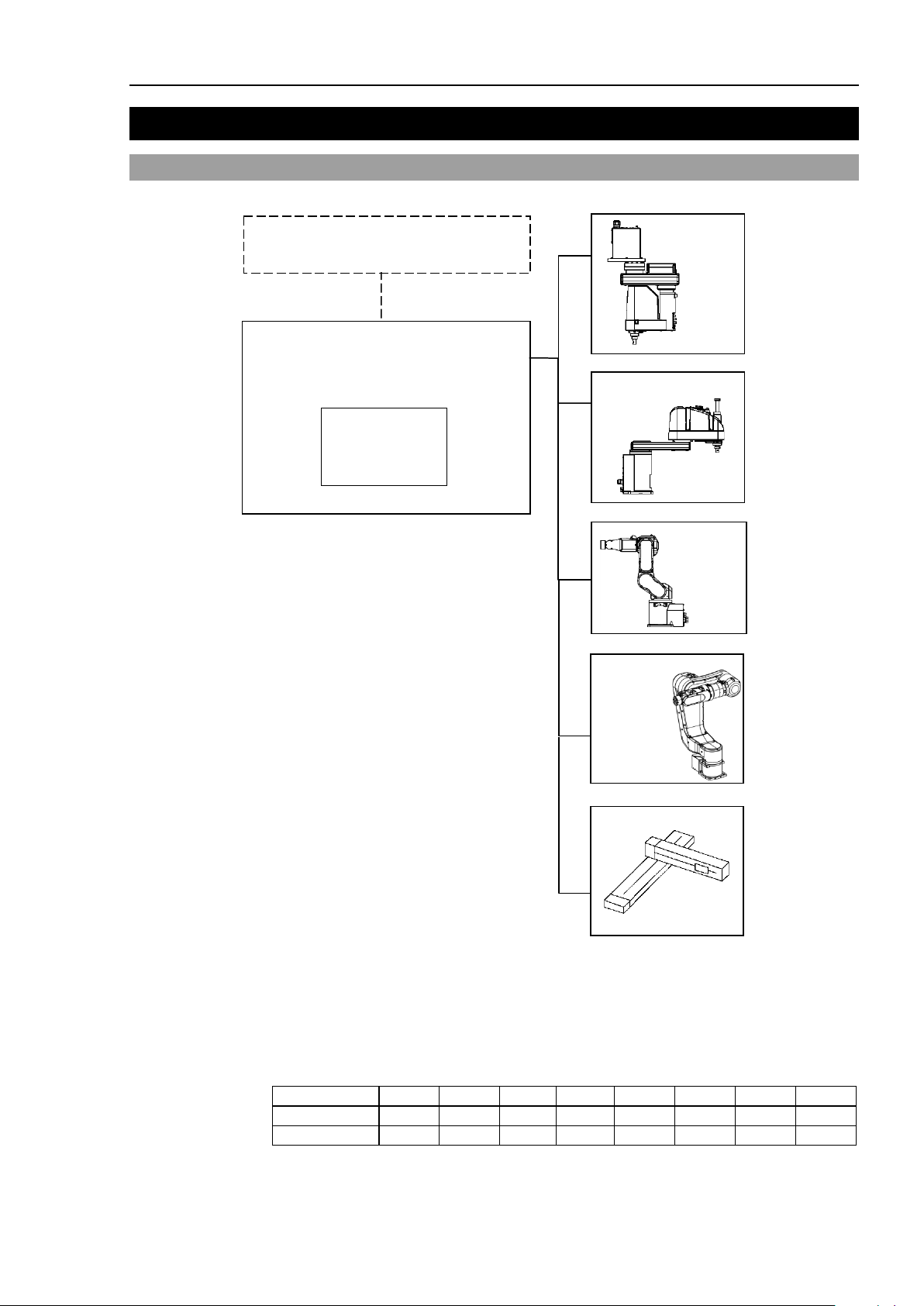
RC700 / RC700-A
RC700DU / RC700DU-A
・EMERGENCY
・Standard I/O
・Remote I/O
・R-I/O
Standard Installation
C4 series
C8 series
G series
RS series
* 2
* 1
X5
N6 series
C4
C8
C12 G RS
N2
N6
X5
RC700DU
- - - - - - - RC700DU-A
-
-
1. Specifications
1.1 System Example
Setup & Operation 1. Specifications
*1 Control Unit
For details, refer to the following manual.
*2 Any one of the Manipulators can be controlled.
Available combinations are as follows. (: connectable)
Robot Controller RC700 / RC700-A
RC700DU / RC700DU-A Rev.11 9
Page 20
Setup & Operation 1. Specifications
DU2
B
A
DU IN
DU1 CU
DU IN
DU OUT
DU OUT
DU3
C
DU IN
DU OUT
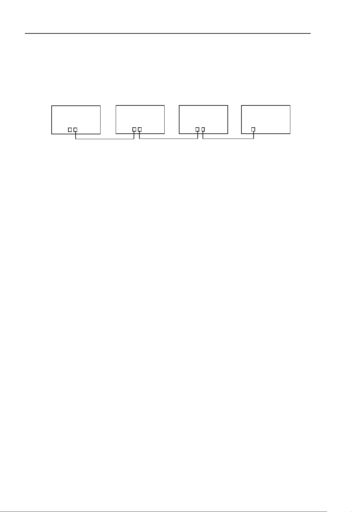
NOTE
Drive Unit is the auxiliary unit connected with the control unit using the special cable.
Drive Unit cannot operate alone.
Up to three Drive Units can be used per robot system.
A: Control Unit and 1st Drive Unit (CU-DU1)
st
B: 1
Drive Unit and 2nd Drive Unit (DU1-DU2)
nd
C: 2
Drive Unit and 3rd Drive Unit (DU2-DU3)
10 RC700DU / RC700DU-A Rev.11
Page 21
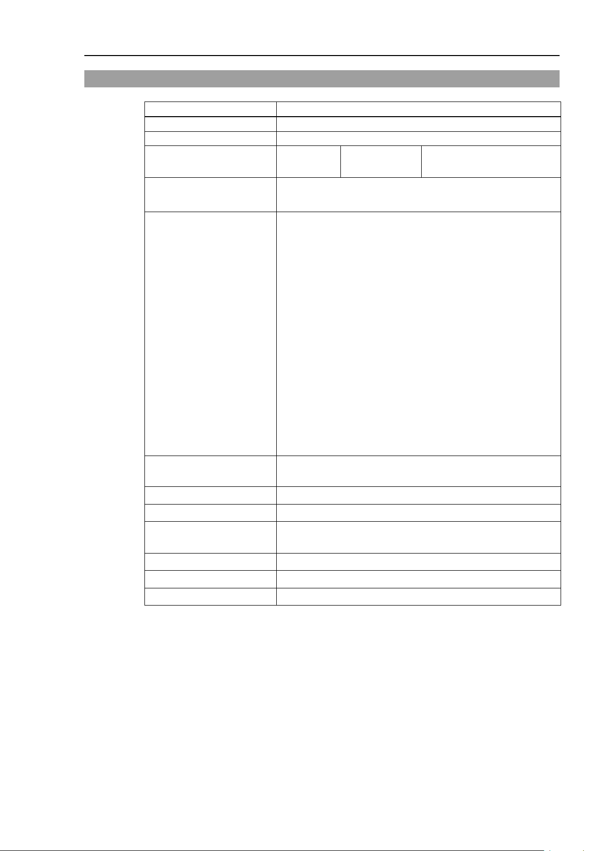
Item
Specification
Model
Drive Unit RC700DU / RC700DU-A
Controllable axes
Up to six (6) connectable AC servo motors
1.2 Drive Unit Standard Specifications
Setup & Operation 1. Specifications
External input/output
signals (standard)
Drive Unit connect interface
(standard)
Safety features
Standard I/O
2 channel
- Emergency stop switch
- Safety door input
- Low power mode
- Dynamic brake
- Motor overload detection
- Irregular motor torque (out-of-control Manipulator) detection
- Motor speed error detection
- Positioning overflow - servo error - detection
- Speed overflow - servo error - detection
- CPU irregularity detection
- Memory check-sum error detection
- Overheat detection at the Motor Driver Module
- Relay welding detection
- Over-voltage detection
- AC power supply voltage reduction detection
- Temperature error detection
- Fan error detection
Input : 24
Output : 16
per Drive Unit
Power Source
Maximum Rated Capacity 2.5 kVA (Depending on the Manipulator model)
Insulation Resistance 100 MΩ or more
Rated Ambient
Temperature
Rated Relative Humidity 20 to 80% (with no condensation)
Weight *1 9 kg
Degree of protection IP20
*1 Weight of the unit is indicated on the Drive Unit itself.
Make sure to check the weight before units transfer or relocation and prevent throwing out your back
at holding the unit.
Also, make sure to keep your hands, fingers, and feet safe from being caught or serious injury.
200 to 240 VAC
Single phase 50/60 Hz
5 to 40 deg.
RC700DU / RC700DU-A Rev.11 11
Page 22
Setup & Operation 1. Specifications
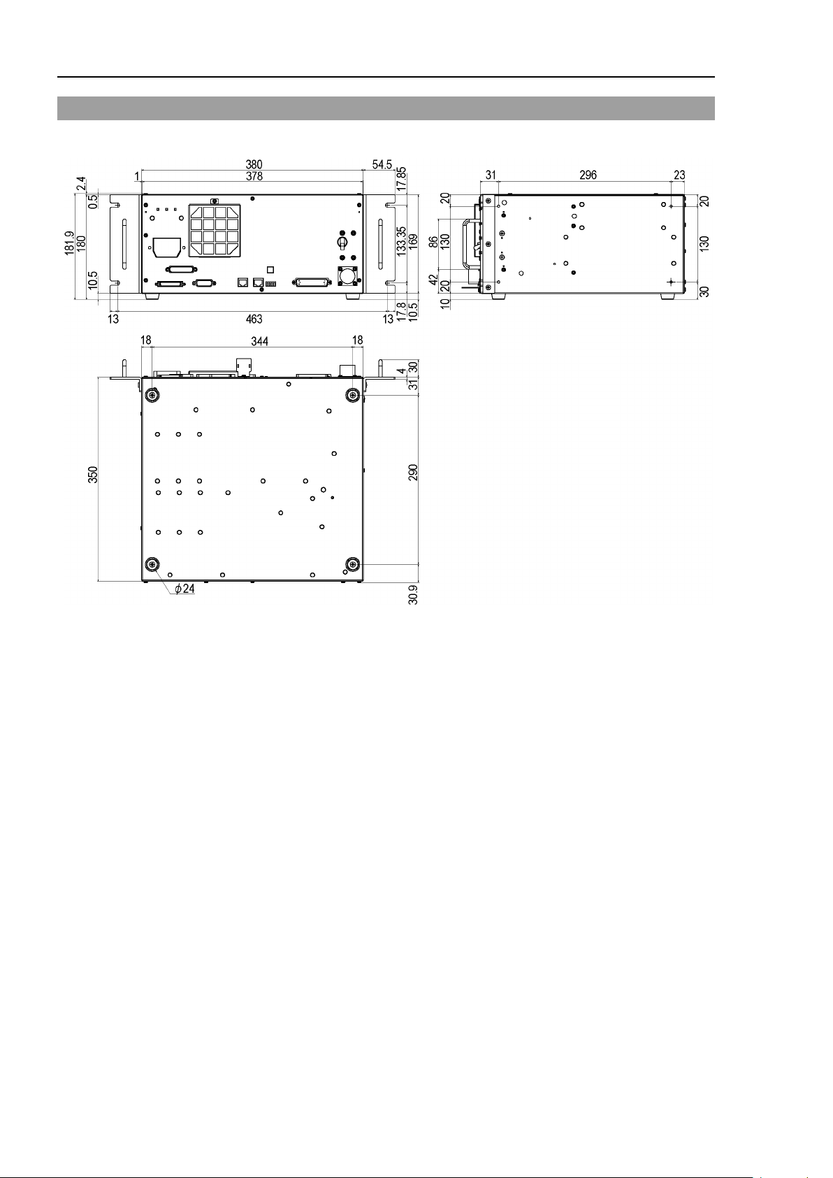
1.3 Outer Dimensions
[Unit : mm]
12 RC700DU / RC700DU-A Rev.11
Page 23
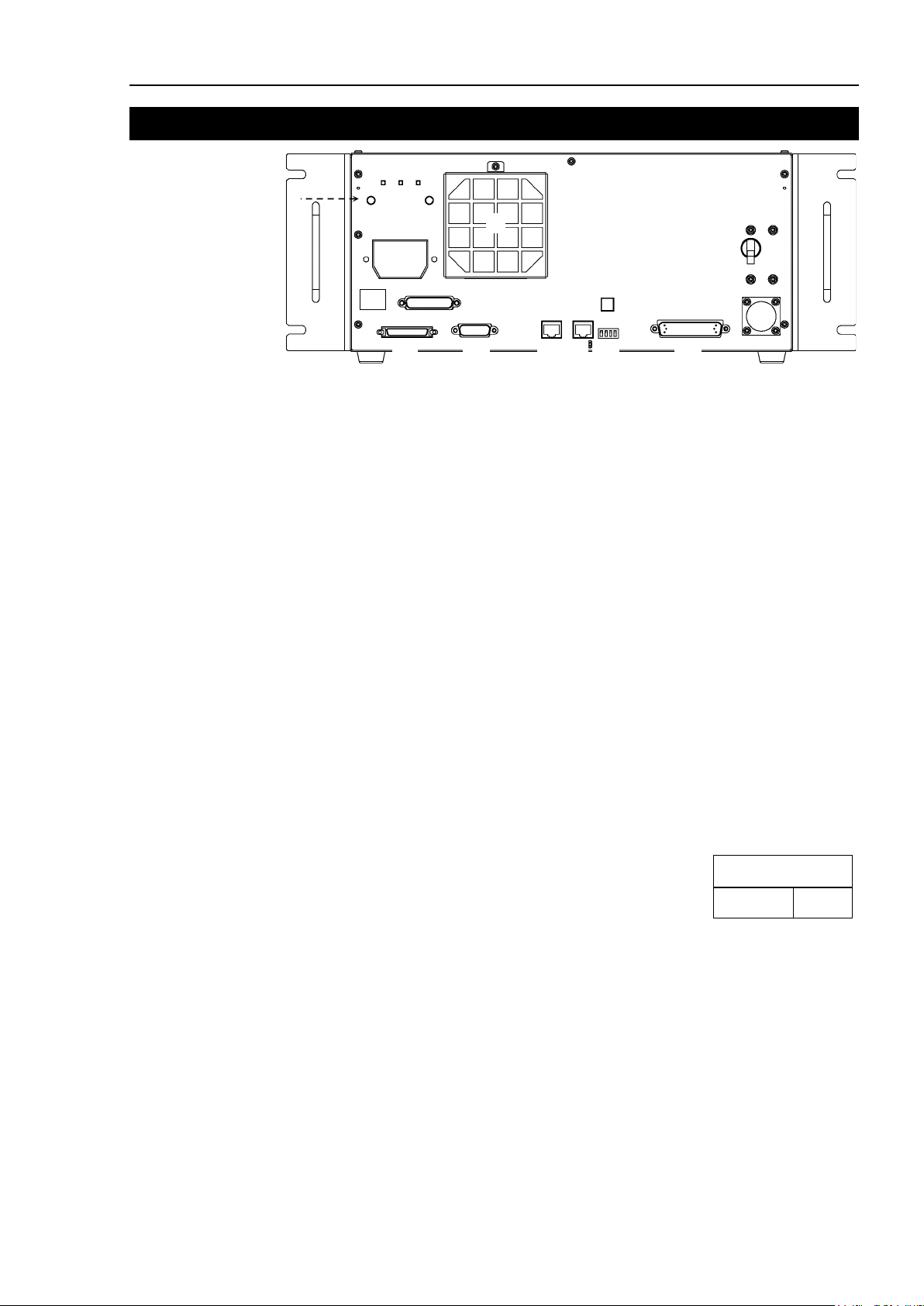
Setup & Operation 2. Part Names and Functions
(2)
(3)
(1)
(Left side)
(4)
(5)
(7) (8)
(6)
(10)
(13)
(14)
(15)
(16)
(11)(12)
(9)
The details of the Manipulator to be connected are recorded
Manipulator model and Manipulator serial number.
MANIPULATOR
00001 C4-A600S
2. Part Names and Functions
(1) Signature label (top panel)
The serial number of the Drive Unit and other information are shown.
(2) LED
The LED indicates current operation mode (RUN, AUTO, ERROR/E-STOP).
For details, refer to Setup & Operation 2.1 LED.
(3) M/C POWER connector
A connector for the Manipulator power source.
Connect the dedicated power cable attached to the Manipulator.
(4) Fan Filter
A protective filter is installed in front of the fan to filter out dust.
Check the condition of the filter regularly and clean it when necessary. A dirty filter
may result in malfunction of the robot system due to temperature rise of the Drive Unit.
For inspection, cleaning, and replacement, refer to the Maintenance 4.1 Fan Filter, 4.2
Fan.
(5) POWER switch
Turns ON or OFF the Drive Unit.
(6) Connection Check label
on the label as shown in the right. The label indicates the
(7) EMERGENCY connector
This connector is used for input/output from/to Emergency Stop and Safety Door
switches. For details, refer to the Setup & Operation 6. EMERGENCY.
RC700DU / RC700DU-A Rev.11 13
Page 24

Setup & Operation 2. Part Names and Functions
Switch
M/C Cable Length
1
3 m 2 5 m
3
10 m
4
15, 20 m
(8) Encoder Voltage Adjustment Switch
Use this switch to adjust voltage according to length of M/C cable. (adjusted as a
factory default)
Wrong setting may result in Robot system malfunction. Do not change the switch.
(9) M/C SIGNAL connector
This connector is used for signals such as the Manipulator’s motor encoders, etc.
Connect the Manipulator’s dedicated signal cable.
(10) R-I/O connector
This connector is for the input signals used for the real time I/O function.
(11) RC700DU: DU OUT Connector / RC700DU-A: OUT Connector
To connect the 2
nd
Drive Unit:
Use the cable attached for Drive Unit and connect with the DU IN connector of the
nd
Drive Unit.
2
To connect the 3
rd
Drive Unit:
Use the cable attached for Drive Unit and connect with the DU IN connector of the
rd
Drive Unit.
3
(12) RC700DU: DU IN Connector / RC700DU-A: IN Connector
st
For the 1
Drive Unit:
Use the cable attached for Drive Unit and connect with the DU OUT connector of
the Control Unit.
nd
For the 2
Drive Unit:
Use the cable attached for Drive Unit and connect with the DU OUT connector of
st
Control Unit.
the 1
rd
For the 3
Drive Unit:
Use the cable attached for Drive Unit and connect with the DU OUT connector of
nd
Control Unit.
the 2
(13) RC700DU / RC700DU-A No. Setting Switch
This switch indicated the Drive Unit number.
For details, refer to the Setup & Operation
(14) I/O connector
This connector is used for input/output device. There are 24 inputs and 16 outputs.
For details, refer to Setup & Operation 7. I/O Connector.
(15) AC IN
The cable for 200VAC power input.
For details, refer to Setup & Operation 3.3.2 AC Power Cable.
(16) Drive Unit Number label
The serial number of the Drive Unit is indicated.
5. Drive Unit Setup.
14 RC700DU / RC700DU-A Rev.11
Page 25
LED
Color
Status
RUN
Green
ON / Flashing / OFF
AUTO
Green
ON / OFF
ERR/E-STOP
Red
ON / Flashing / OFF
DU IN
connector
RUN
AUTO
ERR/E-STOP
LINK (Green)
Power OFF
OFF
OFF
OFF
OFF
Power ON
Flashing
OFF
OFF
OFF
Establishing
the connection
Normally operating
ON
OFF
OFF
Flashing rapidly
LED
Status
Auto mode
ON
ON
-
Flashing rapidly
Program mode
Teach mode
Robot error
ON
-
Flashing
Flashing rapidly
Emergency stop
ON - ON
Flashing rapidly
NOTE
2.1 LED
Setup & Operation 2. Part Names and Functions
Three LEDs are mounted on Drive Unit. They have the following status patterns.
From applying current to Drive Unit to completing startup
Drive Unit LED
Flashing OFF OFF Flashing rapidly
After the connection to Drive Unit is completed
The error information is displayed on the seven-segment display of the Control Unit.
For details, refer to the RC700 / RC700-A Robot Controller manual: Setup & Operation 2.1
LED and Seven-segment LED .
ON OFF - Flashing rapidly
RC700DU / RC700DU-A Rev.11 15
Page 26

Setup & Operation 2. Part Names and Functions
2.2 Safety Features
The robot control system supports safety features described below. However, the user is
recommended to strictly follow the proper usage of the robot system by thoroughly reading
the attached manuals before using the system. Failure to read and understand the proper
usage of the safety functions is highly dangerous.
Among the following safety features, the Emergency Stop Switch and Safety Door Input are
particularly important. Make sure that these and other features function properly before
operating the robot system.
For details, refer to the Setup & Operation 6. EMERGENCY.
Emergency Stop Switch
The EMERGENCY connector on the Drive Unit has expansion Emergency Stop input
terminals used for connecting the Emergency Stop switches.
Pressing any Emergency Stop switch can shut off the motor power immediately and the
robot system will enter the Emergency Stop condition.
Stop category of Emergency Stop input: Category 0 (refer to Safety Standard IEC60204-1)
Safety Door Input
Low Power Mode
Dynamic Brake
In order to activate this feature, make sure that the Safety Door Input switch is connected to
the EMERGENCY connector at the Drive Unit.
When the safety door is opened, normally the Manipulator immediately stops the current
operation, and the status of Manipulator power is operation-prohibited until the safety door
is closed and the latched condition is released. In order to execute the Manipulator
operation while the safety door is open, you must change the mode selector key switch on
the Teach Pendant to the “Teach” mode. Manipulator operation is available only when the
enable switch is on. In this case, the Manipulator is operated in low power status.
Stop category of Safety door input: Category 1 (refer to Safety Standard IEC60204-1)
The motor power is reduced in this mode.
Executing a power status change instruction will change to the restricted (low power) status
regardless of conditions of the safety door or operation mode. The restricted (low power)
status ensures the safety of the operator and reduces the possibility of peripheral equipment
destruction or damage caused by careless operation.
The dynamic brake circuit includes relays that short the motor armatures. The dynamic
brake circuit is activated when there is an Emergency Stop input or when any of the
following errors is detected: encoder cable disconnection, motor overload, irregular motor
torque, motor speed error, servo error (positioning or speed overflow), irregular CPU,
memory check-sum error and overheat condition inside the Motor Driver Module.
Motor Overload Detection
The dynamic brake circuit is activated when the system detects the overload status of the
motor.
Irregular Motor Torque (out-of-control Manipulator) Detection
The dynamic brake circuit is activated when irregular motor torque (motor output) is
detected.
16 RC700DU / RC700DU-A Rev.11
Page 27

Motor Speed Error Detection
The dynamic brake circuit is activated when the system detects that the motor is running at
incorrect speed.
Positioning Overflow –Servo Error- Detection
The dynamic brake circuit is activated when the system detects that the difference between
the Manipulator’s actual position and commanded position exceeds the margin of error
allowed.
Speed Overflow –Servo Error- Detection
The dynamic brake circuit is activated when the Manipulator’s actual speed is detected to
mark an overflow (the actual speed is outside the nominal range) error.
CPU Irregularity Detection
Irregularity of CPU that controls the motor is detected by the watchdog timer. The system
CPU and the motor controlling CPU inside the Drive Unit are also designed to constantly
check each other for any discrepancies. If a discrepancy is detected, the dynamic brake
circuit is activated.
Setup & Operation 2. Part Names and Functions
Memory Check-sum Error Detection
The dynamic brake circuit is activated when a memory check-sum error is detected.
Overheat Detection at the Motor Driver Module
The dynamic brake circuit is activated when the temperature of the power device inside the
Motor Driver module is above the nominal limit.
Relay Deposition Detection
The dynamic brake circuit is activated when relay deposition, junction error, or open fault
is detected.
Over-Voltage Detection
The dynamic brake circuit is activated when the voltage of the Drive Unit is above the
normal limit.
AC Power Supply Voltage Drop Detection
The dynamic brake circuit is activated when the drop of the power supply voltage is detected.
Temperature Anomaly Detection
The temperature anomaly is detected.
Fan Malfunction Detection
Malfunction of the fan rotation speed is detected.
RC700DU / RC700DU-A Rev.11 17
Page 28

Setup & Operation 3. Installation
■
The Manipulator and the
must be used within the environmental
conditions described in their manuals. This product has been designed and
manufactured strictly for use in a normal indoor environment
in the environment that exc
of the
Item
Condition
Use a base table that is at least 100 mm off the floor.
NOTE
3. Installation
3.1 Unpacking
I/O Connector 1 set
Rack-Mount Plate 1 set
Power Cable 1 cable
EMERGENCY port connector 1 set
Connecting cable for RC700DU 1 cable
3.2 Environmental Requirements
Drive Unit
WARNING
. Using the product
eeds the conditions may not only shorten the life cycle
product but also cause serious safety problems.
3.2.1 Environment
In order to optimize the robot system’s performance for safety, the Drive Unit must be placed
in an environment that satisfies the following conditions:
- The Drive Unit is not designed for clean-room specification. If it must be installed in a
clean room, be sure to install it in a proper enclosure with adequate ventilation and cooling.
- Install Drive Unit in a location that allows easy connection / disconnection of cables.
Ambient temperature 5 to 40 deg. (with minimal variation)
Ambient relative humidity 20 to 80% (with no condensation)
Fast transient burst noise 2 kV or less (Power supply wire)
1 kV or less (Signal wire)
Electrostatic noise 4 kV or less
Base table
Placing the Drive Unit directly on the floor could allow
dust penetration leading to malfunction.
If the Drive Unit must be used in an environment that does not fulfill the conditions
mentioned above, take adequate countermeasures. For example, the Drive Unit may be
enclosed in a cabinet with adequate ventilation and cooling.
- Install indoors only.
- Place in a well-ventilated area.
- Keep away from direct sunlight and radiation heat.
- Keep away from dust, oily mist, oil, salinity, metal powder or other contaminants.
- Keep away from water.
- Keep away from shocks or vibrations.
- Keep away from sources of electronic noise
18 RC700DU / RC700DU-A Rev.11
- Do not apply strong electric or magnetic field.
Page 29

Setup & Operation 3. Installation
(A) Flat Mounting
* The rubber foot needs to be replaced.
* A plate for rack mounting is required.
100 mm
200 mm
Excluding the installation side such as base table
Air Flow of
the Drive Unit Fan
50 mm
50 mm
200 mm
NOTE
3.2.2 Installation
Install the Drive Unit on a flat surface such as wall, floor, and Controller box in the direction
shown from (A) to (C).
(B) Upright Mounting (C) Rack Mounting
For Drive Unit installation to the Controller box or the base table, process screw holes as
follows.
- Ensure the draft around the in/out and prevent the other equipment, walls and install the
Drive Unit by keeping the distance as follows for maintenance.
- Hot air with higher temperature than the ambient temperature (about 10 deg.C) comes out
from the Drive Unit. Make sure that heat sensitive devices are not placed near the outlet.
- Arrange the cables in front of the Drive Unit so that you can pull the Drive Unit forward.
RC700DU / RC700DU-A Rev.11 19
Page 30

Setup & Operation 3. Installation
3.2.3 Wall Mounting Option
The Drive Unit has a wall mounting option.
Wall mounting with the front side down Wall mounting with the front side up
Included items of the wall mounting option
WALL FIXING BRACKET 2 brackets
LED DISPLAY FIXING PLATE 1 plate
LED DISPLAY PLATE 1 plate
Screw (M3 × 6 mm) 4 screws
Screw (M4 × 8 mm) 4 screws
Refer to one of the following for the Installation Procedure.
Installation Procedure sheet attached to the Wall Mounting option.
Manual: ROBOT CONTROLLER RC700 / RC700-A
Setup & Operation 3.2.3 Wall Mounting Option
20 RC700DU / RC700DU-A Rev.11
Page 31

Item
Specification
Momentary Power
For approximate power consumption of each model, refer to
model. For details, please contact the supplier of your region.
3.3 Power Supply
3.3.1 Specifications
Ensure that the available power meets following specifications.
Voltage 200 to 240 VAC
Phase Single phase
Frequency 50/60 Hz
Setup & Operation 3. Installation
(
Input voltage should be with in ±10 % of the rated voltage.)
Interrupt
Rated Capacity Maximum : 2.5 kVA
Peak Current When power is turned ON : approximately 85 A (2 ms.)
Leakage Current Max. 10 mA
Ground Resistance
10 msec. or less
Actual power consumption depends on the model, motion, and
load of the Manipulator.
the followings.
C4 : 1.7 kVA
C8 : 2.5 kVA
N6 : 2.2 kVA
G1 : 0.5 kVA
G3 : 1.1 kVA
G6 : 1.5 kVA
G10 : 2.4 kVA
G20 : 2.4 kVA
RS3 : 1.2 kVA
RS4 : 1.4 kVA
Refer to the Manipulator manual for Manipulator rated
capacity.
Rated capacity of X5 varies depending on the Manipulator
When motor is ON : approximately 75 A (2 ms.)
100 Ω or less
Install an earth leakage circuit breaker or a circuit breaker in the AC power cable line at 15
A or less rated electric current. Both should be a two-pole disconnect type. If you install
RC700DU / RC700DU-A Rev.11 21
an earth leakage circuit breaker, make sure to use an inverter type that does not operate by
induction of a 10 kHz or more leakage current. If you install a circuit breaker, please select
one that will handle the above mentioned “peak current”.
The power receptacle shall be installed near the equipment and shall be easily accessible.
Page 32

Setup & Operation 3. Installation
■
Make sure that
■
Be
terminal of the factory power supply. The
at all times to avoid the risk of electric shock.
■
Always use a power plug
for power connecting cable.
Never connect the
■
Select the plug or a disconnecting device which conform safety standards for
nations.
Item
Specification
Black, Black
or Black, White
Ground wire
Green / Yellow
Cable length
3 m
Terminal
M4 round solderless terminal
3.3.2 AC Power Cable
sure to connect the earth wire (green/yellow) of the AC power cable to the earth
WARNING
Make sure to insert the plug of the AC power cable firmly when connecting to the Drive
Unit.
AC power wire (2 cables)
operations are done by a qualified personal.
equipment must be grounded properly
or a disconnecting device
Drive Unit directly to the factory power supply.
22 RC700DU / RC700DU-A Rev.11
Page 33

■
Make sure that the power to the
disconnected
Connecting or
disconnecting
result in
■
Be sure to connect the cables properly. Do not allow un
cables. (Do not put heavy objects on the cables. Do not bend or pull the cables
forcibly.) The unnecessary strain on the cables may result in damage to the
cables, disconnection, and/or contact failure. Damaged cables, disconnec
contact failure is extremely hazardous and may result in electric shock and/or
improper function of the system.
■
The serial number of the Manipulator that should be connected is indicated on the
Connection Check Label on the Drive Unit. Connect the Drive Unit and the
Manipulator correctly. Improper connection between the Drive Unit and the
Manipulator may cause not only improper function of the robot system but also
safety problems.
■
Before connecting the connector, make sure
the pins are not bent.
Connecting with
of
3.4 Cable Connection
electric shock and malfunction of the Drive Unit.
Setup & Operation 3. Installation
Drive Unit is turned OFF and the power plug is
before connecting or disconnecting any cables.
any cables with the power ON is extremely hazardous and may
WARNING
CAUTION
the robot system.
necessary strain on the
tion, or
that
the pins bent may damage the connector and result in malfunction
RC700DU / RC700DU-A Rev.11 23
Page 34

Setup & Operation 3. Installation
Manipulator
1st Drive Unit
(1) AC Power Terminal Block
(2) M/C Power Cable
(3) M/C Signal Cable
(4) EMERGENCY
AC200V-240V
(5) I/O connector
(6) R-I/O connector
(7) DU IN connector
(8) DU OUT connector
Emergency Stop
Safety Door, etc.
Input/Output Device
Disconnectable connector
Cable attached at delivery
Cable prepared by users
2rd Drive Unit
Control Unit
Input/Output Device
Manipulator
2nd Drive Unit
(1) AC Power Terminal Block
(2) M/C Power Cable
(3) M/C Signal Cable
(4) EMERGENCY
AC200V-240V
(5) I/O connector
(6) R-I/O connector
(7) DU IN connector
(8) DU OUT connector
Emergency
Stop
Safety Door, etc.
Input/Output
1st Drive Unit
Input/Output
Manipulator
3rd Drive Unit
(1) AC Power Terminal Block
(2) M/C Power Cable
(3) M/C Signal Cable
(4) EMERGENCY
AC200V-
240V
(5) I/O connector
(6) R-I/O connector
(7) DU IN connector
(8) DU OUT connector
(D
o not connect anything.)
Emergency Stop
Safety Door, etc.
Input/Output
2nd Drive Unit
Input/Output
3rd Drive Unit
3.4.1 Typical Cable Connection
24 RC700DU / RC700DU-A Rev.11
Page 35

Setup & Operation 3. Installation
(1)
AC Power terminal block
(2)
M/C Power cable
the Manipulator and the M/C POWER
(3)
M/C Signal cable
(4)
EMERGENCY
(5)
I/O connector
(6)
R-I/O Connector
(7)
DU IN connector
(8)
DU OUT connector
connector on the 2nd Drive Unit.
Terminal block for 200VAC power input to the Drive Unit.
The cable with 50-pin connector on the Drive Unit side.
Connect the POWER connector on
connector on the Drive Unit. Insert the connectors until you hear a “click”.
The cable with 50-pin connector on the Drive Unit side.
Connect the signal cable to the SIGNAL connector on the Manipulator and the M/C
SIGNAL connector on the Drive Unit.
The EMERGENCY connector has inputs to connect the Emergency Stop switch
and the Safety Door switch. For safety reasons, connect proper switches for these
input devices.
For details, refer to the Setup & Operation 6. EMERGENCY.
This connector is used for input/output devices of the user.
When there are input/output devices, use this connector.
There are I/O cable (option) and terminal block (option) for the I/O connector.
For details, refer to the Setup & Operation 7. I/O Connector.
This connector is used for connecting with input signals necessary for real time I/O
function.
For details, refer to the Setup & Operation 13. R-I/O Connector.
For the 1st Drive Unit:
Use the cable attached for Drive Unit and connect with the DU OUT connector of
the Control Unit.
For the 2
nd
Drive Unit:
Use the cable attached for Drive Unit and connect with the DU OUT connector
of the 1
For the 3
st
Control Unit.
rd
Drive Unit:
Use the cable attached for Drive Unit and connect with the DU OUT connector
of the 2
nd
Control Unit.
RC700DU / RC700DU-A Rev.11 25
To connect the 2nd Drive Unit:
Use the cable attached for Drive Unit and connect with the DU IN connector of the
nd
2
Drive Unit.
To connect the 3
rd
Drive Unit:
Use the cable attached for Drive Unit and connect with the DU IN connector of
rd
the 3
Drive Unit.
* Be sure not to connect anything to this connector when using only one Drive
rd
Unit. Also, when using the 3
Drive Unit, do not connect anything to this
Page 36

Setup & Operation 3. Installation
■
Make sure that the power to the
turned OFF before connecting or
disconnecting any cables.
ON
Drive Unit
■
Be sure to connect the cables properly. Do not allow unnecessary strain on the
cables. (Do not put heavy objects on the cables. Do not bend or pull the
forcibly.) The unnecessary strain on the cables may result in damage to the cables,
disconnection, and/or contact failure. Damaged cables, disconnection, or contact
failure is extremely hazardous and may result in electric shock and/or improper
fu
■
The serial number of the Manipulator that should be connected is indicated on the
Improper
Manipulator may cause not only improper
NOTE
3.4.2 Connecting Manipulator to Drive Unit
Connect the Manipulator to the Drive Unit by using the Power cable and the Signal cable.
is extremely hazardous and may result in electric shock and malfunction of the
.
Drive Unit is
Connecting or disconnecting any cables with the power
WARNING
nction of the system.
CAUTION
Drive Unit. Connect the Drive Unit and the Manipulator correctly.
connection between the Drive Unit and the
function of the robot system but also serious safety problems.
The configuration data for the Manipulator and Manipulator model are stored in the Drive
Unit. Therefore the Drive Unit should be connected to the Manipulator whose serial
number is specified in the Connection Check label attached on the front of the Drive Unit.
The Manipulator’s serial number is indicated on the signature label on the back of the
Manipulator.
cables
26 RC700DU / RC700DU-A Rev.11
Page 37

AC Line duct
DC line duct
As far as possible
3.5 Noise Countermeasures
To minimize electrical noise conditions, the following items must be observed in the
system’s cable wiring:
To minimize electrical noise condition, be sure of followings for wiring.
- The earth wire of the power supply should be grounded. (Ground resistance: 100 Ω or
less) It is important to ground the frame of Drive Unit not only for prevention from
electric shock, but also for reducing the influence of electric noise around the Drive Unit.
Therefore, be sure to connect the earth wire (yellow/green) of the Drive Unit’s power
cable to the ground terminal of the factory power supply. For details about the plug
and AC power cable, refer to the Setup & Operation 3.3 Power Supply.
- Do not tap power from a power line that connects to any equipment which may cause
noise.
- When you tap power for the Drive Unit and the single-phase AC motor from the same
power line, change the phase of one or the other. Ensure that they will not be the same
phase.
- Use a twisted pair motor power line.
Setup & Operation 3. Installation
- Do not run AC power lines and DC power lines in the same wiring duct, and separate
them as far as possible. For example, separate the AC motor power line and the Drive
Unit power line as far as possible from the sensor or valve I/O lines; and do not bundle
both sets of wiring with the same cable tie. If more than one duct/cable must cross each
other, they should cross perpendicularly. The preferable example is shown in the right
figure.
- Wire as short as possible to the I/O connector and EMERGENCY connector. Use a
shielded cable and clamp the shield to the attached connector interior. Make sure to
keep away from the peripheral noise source as far as possible.
- Make sure that the induction elements used to connect to the Drive Unit’s I/O (such as
relays and solenoid valves) have surge suppressors. If an induction element without a
surge suppressor is used, make sure to connect a rectifying diode located at the induction
element in parallel with it. In selecting a rectifying diode, make sure that it can handle
the voltage and current incurred by the induction load.
- To start and change revolutions of the conveyer’s (or the like’s) AC motor (ex: an
induction motor or three-phase induction motor) regularly or abruptly, make sure to
install a spark suppressor between the wires. The spark suppressor is more effective
when placed closer to the motor.
- As they are easily influenced by noise, keep cable such as USB, Ethernet, RS-232C, or
fieldbus away from peripheral noise sources.
RC700DU / RC700DU-A Rev.11 27
Page 38

Setup & Operation 4. Drive Unit Connection
DU IN*
DU OUT
*
DU OUT*
Drive Unit (DU): RC700DU / RC700DU-A
Control Unit (CU): RC700CU / RC700CU-A
DU2
B
A
DU IN
DU1 CU
DU IN
DU OUT
DU OUT
DU3
C
DU IN
DU OUT
NOTE
NOTE
4. Drive Unit Connection
Drive Unit is connected to the Control Unit using the attached connection cable.
Up to three Drive Units can be connected to the Control Unit.
A: Control Unit and 1st Drive Unit (CU-DU1)
st
B: 1
Drive Unit and 2nd Drive Unit (DU1-DU2)
nd
C: 2
Drive Unit and 3rd Drive Unit (DU2-DU3)
(Figure: RC700DU , RC700)
* Name: RC700-A, RC700DU-A: OUT, IN
When you use one Drive Unit
:
Connect nothing to DU OUT of the 1st Drive Unit (DU1). Otherwise, it results in the Robot
Controller malfunction.
When you use two Drive Units
:
Connect nothing to DU OUT of the 2nd Drive Unit (DU2). Otherwise, it results in the
Robot Controller malfunction.
When you use three Drive Units
:
Connect nothing to DU OUT of the 3rd Drive Unit (DU3). Otherwise, it results in the Robot
Controller malfunction.
When connecting the connection cable, make sure to connect to DU IN and DU OUT
properly. Improper connection may cause malfunction.
Do not use any LAN cables on the market. Otherwise, it results in the Robot Controller
malfunction.
How to turn on the power switch:
Check the connection first. Then, make sure to turn on the power switch of Drive Unit
before turning on the power switch of Control Unit.
28 RC700DU / RC700DU-A Rev.11
Page 39

5. Drive Unit Setup
(1) Turn OFF the Drive Unit.
(2) Change the DIP
DIP switch
1 2 3 4
ON
OFF
ALL OFF
1 2 3 4
ON
OFF
ON : 1
OFF : 2, 3, 4
1 2 3 4
ON
OFF
ON : 2
OFF : 1, 3, 4
(3) A
(4) Plug in
The DIP switch is equipped on the front side to configure 1st, 2nd ,and 3rd Drive Unit.
Follow the steps below to set up the Drive Unit.
Setup & Operation 5. Drive Unit Setup
switch.
1st Drive Unit
2nd Drive Unit
3rd Drive Unit
ttach the DU number label on Drive Unit.
DU1 : 1
DU2 : 2
DU3 : 3rd Drive Unit
the power connector. Turn ON the Drive Unit.
st
Drive Unit
nd
Drive Unit
RC700DU / RC700DU-A Rev.11 29
Page 40

Setup & Operation 5. Drive Unit Setup
(1) Select t
[System Configuration] dialog box will appear.
(2)
(3)
(2) Click
(3) Click <
[Add New Robot] dialog box will appear.
(4)
Adding of information of the new system is required only for customers who purchased the
Drive Unit singly.
Set up the Control Unit and Drive Unit and turn on the robot system. If information of the new
system was not added, follow the steps below to add information.
he EPSON RC+ 7.0-[Setup]-[System Configuration].
[Controller]-[Robots] in the tree on the left.
Add> button.
30 RC700DU / RC700DU-A Rev.11
Page 41

Setup & Operation 5. Drive Unit Setup
(4) Enter the following items by referring to the
Sheet
Item
Description
Robot Name :
Type in a name for the new Manipulator. (Example: RB1
Robot1)
Robot Serial # :
Type in “Serial No.” on the Hofs sheet.
number described above.
Motion System :
Select “Standard”.
be already selected.
Drive Unit :
Select a Drive Unit for your Manipulator. (DU1, DU2, DU3)
and indicated by the indication labels.
Robot Type :
Select a Manipulator type.
Robot Joints :
This item cannot be changed.
Series :
Select a Manipulator series.
Model :
Select a Manipulator model.
in the Drive Unit will be displayed.
(5) Click <
(6) Click
Following dialog box will appear.
(6)
(7)
(8)
(9)
(7) Type in the values on the Hofs sheet to [CalPls] and [Hofs].
(8) Click
(9) Click
RC700DU Robot System Hofs Data
(hereinafter referred to as Hofs sheet) which is included with shipment.
(or the serial number on the Manipulator’s nameplate)
Any serial number can be used, but it is recommended to use the
If there are no other motion systems installed, “Standard” should
DU numbers are configured by the dip switch on the front side
All Manipulators available for the motor driver currently installed
OK> button. The EPSON RC+ will restart.
[Controller]-[Robots]-[Robot **]-[Calibration] in the tree on the left.
<Apply> button.
<Close> button.
RC700DU / RC700DU-A Rev.11 31
Page 42

Setup & Operation 6. EMERGENCY
WARNING
■
Not only when turning on the device, but also changing use environment such as
add options or replace
or safety door work properly.
WARNING
■
Before connecting the connector, make sure
the pins are not bent.
Connecting with
of
EMERGENCY Connector
D-sub 25 male pin
■
The interlock of the Safety Door must be functioning when the
operated.
be turned ON/OFF (e.g. The tape is put around the switch.). Operating the robot
system when the switch is not
may
intended function
NOTE
6. EMERGENCY
The details of safety requirements for this section are described in User’s Guide 2. Safety.
Please refer to them to keep the robot system safe.
Connect a safeguard switch or Emergency Stop switch to the Drive Unit EMERGENCY
connector for safety.
When nothing is connected to the EMERGENCY connector, the Drive Unit does not operate
normally.
the robot system.
the pins bent may damage the connector and result in malfunction
parts for maintenance, make sure that the emergency stop
that
6.1 Safety Door Switch and Latch Release Switch
The EMERGENCY connector has input terminals for the Safety Door switch and the
Emergency Stop switch. Be sure to use these input terminals to keep the system safe.
Connector Standard
EMERGENCY connector
(Drive Unit side)
* The connector cable, terminal block, and connector kit are offered as options.
Mounting style #4 - 40
6.1.1 Safety Door Switch
Do not operate the system under the condition that the switch cannot
WARNING
32 RC700DU / RC700DU-A Rev.11
cause serious safety problems as the Safety Door input cannot fulfill its
.
In order to maintain a safe working zone, a safeguard must be erected around the
Manipulator. The safeguard must have an interlock switch at the entrance to the working
zone. The Safety Door that is described in this manual is one of the safeguards and an
interlock of the Safety Door is called a Safety Door switch. Connect the Safety Door
switch to the Safety Door input terminal on the EMERGENCY connector.
The Safety Door switch has safety features such as temporary hold-up of the program or the
operation-prohibited status that are activated whenever the Safety Door is opened.
functioning properly is extremely hazardous and
robot system is
Page 43

Setup & Operation 6. EMERGENCY
NOTE
NOTE
Observe the followings in designing the Safety Door switch and the Safety Door.
- For the Safety Door switch, select a switch that opens as the Safety Door opens, and not
by the spring of the switch itself.
- The signal from the Safety Door (Safety Door input) is designed to input to two
redundant signals. If the signals at the two inputs differ by two seconds or more, the
system recognizes it to be a critical error. Therefore, make sure that the Safety Door
switch has two separate redundant circuits and that each connects to the specified pins at
the EMERGENCY connector on the
Drive Unit.
- The Safety Door must be designed and installed so that it does not close accidentally.
6.1.2 Latch Release Switch
The software latches these conditions:
- The safety door is open.
- The operation mode is set to “TEACH”.
The EMERGENCY connector has an input terminal for a latch release switch that cancels
the latched conditions.
Open : The latch release switch latches conditions that the safety door is open or the
operation mode is “TEACH”.
Closed : The latch release switch releases the latched conditions.
When the latched TEACH mode is released while the safety door is open, the status of
Manipulator power is operation-prohibited because the safety door is open at that time.
To execute a Manipulator operation, close the safety door again, and then close the latch
release input.
6.1.3 Checking Latch Release Switch Operation
After connecting the safety door switch and latch release switch to the EMERGENCY
connector, be sure to check the switch operation for safety by following the procedures
described below before operating the Manipulator.
(1) Turn ON the Controller while the safety door is open in order to boot the software.
(2) Make sure that “Safety” is displayed on the main window status bar.
(3) Close the safety door, and turn ON the switch connecting to the latch release input.
Make sure that the “Safety” is dimmed on the status bar.
The information that the safety door is open can be latched by software based on the
latch release input condition.
Open : The latch release switch latches the condition that the safety door is open.
To cancel the condition, close the safety door, and then close the safety door latch
release input.
Closed : The latch release switch does not latch the condition that the safety door is open.
The latch release input also functions to acknowledge the change of to TEACH mode.
In order to change the latched condition of TEACH mode, turn the mode selector key switch
on the Teach Pendant to “Auto”. Then, close the latch release input.
RC700DU / RC700DU-A Rev.11 33
Page 44

Setup & Operation 6. EMERGENCY
NOTE
6.2 Emergency Stop Switch Connection
6.2.1 Emergency Stop Switch
If it is desired to add an external Emergency Stop switch(es) in addition to the Emergency
Stop on the Teach Pendant, be sure to connect such Emergency Stop switch(es) to the
Emergency Stop input terminal on the EMERGENCY connector.
The Emergency Stop switch connected must comply with the related safety standards (such
as
IEC60947-5-5) and the following:
- It must be a push button switch that is “normally closed”.
- A button that does not automatically return or resume.
- The button must be mushroom-shaped and red.
- The button must have a double contact that is “normally closed”.
The signal from the Emergency Stop switch is designed to use two redundant circuits.
If the signals at the two circuits differ by two seconds or more, the system recognizes it as
a critical error. Therefore, make sure that the Emergency Stop switch has double
contacts and that each circuit connects to the specified pins on the EMERGENCY
connector at the
6.2.2 Checking Emergency Stop Switch Operation
Drive Unit. Refer to the Setup & Operation 6.4 Circuit and Wiring.
Once the Emergency Stop switch is connected to the EMERGENCY connector, continue
the following procedure to make sure that the switch functions properly. For the safety
of the operator, the Manipulator must not be powered ON until the following test is
completed.
(1) Turn ON the Controller to boot the software while pressing the Emergency Stop switch.
(2) Make sure that “ERROR/E-STOP” LED on Drive Unit has been turned ON.
(3) Make sure that “E.Stop” is displayed on the status bar on the EPSON RC+ main
window.
(4) Release the Emergency Stop Switch.
(5) Execute the RESET command.
(6) Make sure that
“ERROR/E-STOP” LED turns OFF and “E-Stop” display fades on the
main window status bar.
6.2.3 Recovery from Emergency Stop
To recover from the emergency stop condition, follow the procedure of safety check as
required by the system.
After safety check, the operations below are required to recover from the emergency stop
condition.
- Release the Emergency Stop Switch
- Execute the RESET command
34 RC700DU / RC700DU-A Rev.11
Page 45

Setup & Operation 6. EMERGENCY
1
ESW11
Emergency Stop switch contact (1) *3
14
ESW21
Emergency Stop switch contact (2) *3
2
ESW12
Emergency Stop switch contact (1) *3
15
ESW22
Emergency Stop switch contact (2) *3
3
ESTOP1+
Emergency Stop circuit 1 (+) *4
16
ESTOP2+
Emergency Stop circuit 2 (+) *4
4
ESTOP1−
Emergency Stop circuit 1 (-) *4
17
ESTOP2−
Emergency Stop circuit 2 (-) *4
5
Not Used
18
SDLATCH1
Safety Door Latch Release
6
Not Used
19
SDLATCH2
Safety Door Latch Release
7
SD11
Safety Door input (1) *2
20
SD21
Safety Door input (2) *2
8
SD12
Safety Door input (1) *2
21
SD22
Safety Door input (2) *2
9
24V
+24V output
22
24V
+24V output
10
24V
+24V output
23
24V
+24V output
11
24VGND
+24V GND output
24
24VGND
+24V GND output
12
24VGND
+24V GND output
25
24VGND
+24V GND output
13
Not Used
■
The 24 V output is for emergency stop. Do not use it for other purposes. Doing
so may result in system
■
The 24 V output is for emergency stop. Do not use it for other purposes. Doing
so may result in system
NOTE
6.3 Pin Assignments
The EMERGENCY connector (D-sub25 male) pin assignments are as follows:
Pin No. Signal Function Pin No. Signal Function
*1
*1
*1 Do not connect anything to these pins.
*2 A critical error occurs if the input values from the Safety Door 1 and Safety Door 2 are
different for two or more seconds. They must be connected to the same switch with
two sets of contacts.
*3 A critical error occurs if the input values from the Emergency Stop switch contact 1
and Emergency Stop switch contact 2 are different for two or more seconds. They
must be connected the same switch with two sets of contacts.
*4 Do not apply reverse voltage to the Emergency Stop circuit.
Emergency Stop switch output rated load +30 V 0.3 A or under 1-2, 14-15 pin
Emergency Stop rated input voltage range
Emergency Stop rated input current
Safety Door rated input voltage range
Safety Door rated input current
Latch Release rated input voltage range
Latch Release rated input current
+24 V ±10%
47.5 mA/+24 V input
+24 V ±10%
10 mA/+24 V input
+24 V ±10%
10 mA/+24 V input
3-4, 16-17 pin
7-8, 20-21 pin
18-19 pin
The total electrical resistance of the Emergency Stop switches and their circuit should be 1
Ω or less.
malfunction.
CAUTION
malfunction.
RC700DU / RC700DU-A Rev.11 35
Page 46

Setup & Operation 6. EMERGENCY
Drive Unit
Safety Door input 1
Safety Door input 2
Latch release input
Main Circuit
Control
Emergency
Stop detection
ESTOP1+
ESTOP2+
ESTOP1−
ESTOP2−
Be careful of
the direction
of voltage
application
6.4 Circuit and Wiring
6.4.1 Circuit Diagram
36 RC700DU / RC700DU-A Rev.11
Page 47

Setup & Operation 6. EMERGENCY
Emergency stop switch
Terminal block
Emergency
Stop switch of
an Operation
Unit (TP)
NOTE
6.4.2 Wiring Example for Emergency Stop
6.4.2.1 External emergency stop switch typical application
The Emergency cable, Emergency cable kit, and Terminal block are offered as options.
Design the cables connecting the units within 20 m long.
RC700DU / RC700DU-A Rev.11 37
Page 48

Setup & Operation 6. EMERGENCY
External
safety relay
External +24V
GND
External +24V
Fuse *
External
+24V
Emergency
Stop switch
Terminal block
External
+24V
GND
External
+24V
GND
External
+24V
GND
6.4.2.2 External safety relay typical application
* Fuse
For the protection of the emergency stop circuit, the fuse’s capacity should be as follows:
- Meets the capacity of the external
- 0.4A or less
38 RC700DU / RC700DU-A Rev.11
Page 49

Setup & Operation 6. EMERGENCY
Safety Door input 1
Safety Door input 2
Latch release input
Latch release input
Close :Latch off
Open :Latch on
External
External
Safety Door input 1
Safety Door input 2
Latch release input
Safety Door input 1
Safety Door input 2
Latch release input
Safety Door input 1
Safety Door input 2
Latch release input
NOTE
6.4.3 Wiring Example for Safety Door Input / Latch Release Input
Design the cables connecting the units within 20 m long.
RC700DU / RC700DU-A Rev.11 39
Page 50

Setup & Operation 7. I/O Connector
Pins
Bit number
Input
24
0 to 23
Output
16
0 to 15
Input
24
32 to 55
Output
16
32 to 47
Input
24
256 to 279
Output
16
256 to 271
Input
24
288 to 311
Output
16
288 to 303
7. I/O Connector
The I/O connector is for connecting your input/output equipment to the system.
Control Unit
Drive Unit 1
Drive Unit 2
Drive Unit 3
For cable wiring, refer to the Setup & Operation 3.5 Noise Countermeasures in order to
prevent noise.
7.1 Input Circuit
Input Voltage Range : +12 to 24 V ±10%
ON Voltage : +10.8 V (min.)
OFF Voltage : +5 V (max.)
Input Current : 10 mA (TYP) at +24 V input
Two types of wiring are available for use with the two-way photo coupler in the input circuit.
40 RC700DU / RC700DU-A Rev.11
Page 51

Typical Input Circuit Application 1
I/O-1
(Same)
Omit
GND +DC
34 Input No.16~23 common
Omit
26 Input No.15
42 Input No.23
35 Input No.16
36 Input No.17
1 Input No.0 to 7 common
2 Input No.0
3 Input No.1
4 Input No.2
5 Input No.3
6 Input No.4
7 Input No.5
8 Input No.6
9 Input No.7
18 Input No.8 to 15 common
19 Input No.8
20 Input No.9
(Same)
(Same)
(Same)
(Same)
(Same)
(Same)
(Same)
(Same)
(Same)
(Same)
(Same)
(Same)
Setup & Operation 7. I/O Connector
RC700DU / RC700DU-A Rev.11 41
Page 52

Setup & Operation 7. I/O Connector
I/O-1
(
Same
)
Omit
GND +DC
34 Input No.16~23 common
Omit
26 Input No.15
42 Input No.23
35
Input No.16
36 Input No.17
1 Input No.0 to 7 common
2 Input No.0
3 Input No.1
4 Input No.2
5 Input No.3
6 Input No.4
7 Input No.5
8 Input No.6
9 Input No.7
18 Input No.8 to 15 common
19 Input No.8
20 Input No.9
(Same)
(Same)
(
Same
)
(Same)
(Same)
(Same)
(
Same
)
(Same)
(Same)
(Same)
(Same)
(Same)
Typical Input Circuit Application 2
42 RC700DU / RC700DU-A Rev.11
Page 53

7.2 Output Circuit
10 Output No.0
I/O-1
(Same)
Omit
+DC
29 Output No.8
30 Output No.9
11 Output No.1
12 Output No.2
13 Output No.3
14 Output No.4
15 Output No.5
27 Output No.6
28 Output No.7
17 Output No.0 to 7 common (GND)
Load
L
GND
L
33 Output No.8 to 15 common (GND)
(Same)
(Same)
(Same)
(Same)
(Same)
(Same)
(Same)
(Same)
Rated Output Voltage : +12 V to 24 V ±10%
Maximum Output Current : TYP 100 mA/1 output
Output Driver : PhotoMOS Relay
On-State Resistance (average) : 23.5 Ω or less
Two types of wiring are available for use with the nonpolar PhotoMOS relay in the output
circuit.
Typical Output Circuit Application 1: Sink Type (NPN)
Setup & Operation 7. I/O Connector
RC700DU / RC700DU-A Rev.11 43
Page 54

Setup & Operation 7. I/O Connector
10 Output No.0
I/O-1
(Same)
Omit
+DC
29 Output No.8
30 Output No.9
11 Output No.1
12 Output No.2
13 Output No.3
14 Output No.4
15 Output No.5
27 Output No.6
28 Output No.7
17 Output No.0 to 7 common (+DC)
Load
L
GND
L
33 Output No.8 to 15 common (+DC)
(Same)
(Same)
(Same)
(Same)
(Same)
(Same)
(Same)
(Same)
Typical Output Circuit Application 2: Source Type (PNP)
44 RC700DU / RC700DU-A Rev.11
Page 55

7.3 Pin Assignments
Pin
No.
Pin
No.
Pin
No.
1
Input common No. 0 to 7
18
Input common No. 8 to 15
34
Input common No. 16 to 23
2
Input No. 0
19
Input No. 8
35
Input No. 16
3
Input No. 1
20
Input No. 9
36
Input No. 17
4
Input No. 2
21
Input No. 10
37
Input No. 18
5
Input No. 3
22
Input No. 11
38
Input No. 19
6
Input No. 4
23
Input No. 12
39
Input No. 20
7
Input No. 5
24
Input No. 13
40
Input No. 21
8
Input No. 6
25
Input No. 14
41
Input No. 22
9
Input No. 7
26
Input No. 15
42
Input No. 23
10
Output No. 0
27
Output No. 6
43
Output No.11
11
Output No. 1
28
Output No. 7
44
Output No.12
12
Output No. 2
29
Output No. 8
45
Output No.13
13
Output No. 3
30
Output No. 9
46
Output No.14
14
Output No. 4
31
Output No.10
47
Output No.15
15
Output No. 5
32
Not Used
48
Not Used
16
Not Used
33
Output common No. 8 to 15
49
Not Used
17
Output common No. 0 to 7
50
Not Used
Setup & Operation 7. I/O Connector
Signal Name
Signal Name
Signal Name
Remote function is not initially assigned to both input and output. To assign the remote function, refer to
RC700
/ RC700-A Robot Controller: Setup & Operation 12. I/O Remote Settings.
Connector Standard
I/O Connector (Drive Unit side)
D-sub 50 male pin
Mounting style #4 - 40
* The I/O connector, I/O connector cable, terminal block, and I/O connector kit are offered as options.
RC700DU / RC700DU-A Rev.11 45
Page 56

Setup & Operation 8. R-I/O Connector
Pins
Bit number
Drive Unit 1
Input 2 56, 57
Drive Unit 2
Input 2 280, 281
Drive Unit 3
Input 2 312,313
R-I/O
Input No.56-1
Input No.56-2
Input No.57-1
Input No.57-2
GND +24V
8. R-I/O Connector
The I/O connector is for connecting the input signals of the real time I/O function.
By inputting trigger signals to R-I/O, you can keep and get the operating robot position when
trigger is detected. If you use this function with Vision, you can create an application of
parts pickup, alignment, and assembly by robots without stopping.
For details, refer to EPSON RC+7.0 User’s Guide 18. Real time I/O.
8.1 Input Circuit
Input Voltage Range : +24 V ±10%
Input Current : 10 mA (TYP) at +24 V input
The following two types of wiring are available in the input circuit.
Typical Input Circuit Application 1
46 RC700DU / RC700DU-A Rev.11
Page 57

Typical Input Circuit Application 2
R-I/O
Input No.56-1
Input No.56-2
Input No.57-1
Input No.57-2
GND +24V
3
Input No57-1
Input No.281-1
Input No313-1
Connector
Standard
■
When using R
I/O connector without meeting
conditions, it may cause the system
failure and/or safety problems.
8.2 Pin Assignments
Setup & Operation 8. R-I/O Connector
Pin No.
Signal Name
(Drive Unit 1)
Signal Name
(Drive Unit 2)
Signal Name
(Drive Unit 3)
1 Input No.56-1 Input No.280-1 Input No312-1
2 Input No56-2 Input No.280-2 Input No312-2
4 Input No57-2 Input No.281-2 Input No313-2
5 to 15* Not Used
* For the pins 5 to 15, do not connect anything.
I/O Connector (Drive Unit side)
D-sub 50 male pin
Mounting style #4 - 40
-I/O connector, be careful of the following points. If you use the Rthe necessary
CAUTION
- Use a shielded cable and route the cables as far from the surrounding noise
sources as possible.
For details, refer to Setup & Operation: 3.5
- Make sure to check the cable routing before turning on the power supply.
Noise Countermeasures.
RC700DU / RC700DU-A Rev.11 47
Page 58

Setup & Operation 8. R-I/O Connector
48 RC700DU / RC700DU-A Rev.11
Page 59

Maintenance
This section contains maintenance procedures for the Drive Unit.
Page 60

Page 61

Maintenance 1. Safety Precautions on Maintenance
■
Only authorized personnel who have taken the safety training should be allowed
to
The safety training is the program for industrial robot operator that follows the laws
and regulations of each nation. T
acquire knowledge of industrial robots (operations, teaching, etc.).
The personnel who have completed the robot system
manufacturer, dealer, or locally
robot system.
■
Only authorized personnel who have taken the safety training should be allowed
to maintain the robot system.
The safety training is the program for industrial robot operator that follows the laws
and regulations of each nation.
The personnel who have t
robots (operations, teaching, etc.), knowledge of inspections, and knowledge of
related rules/regulations.
The personnel who have completed the robot
training classe
are allowed to maintain the robot system.
■
Make sure to use only dedicated/specified maintenance parts especially for the
optional boards or any other
to be replaced.
Using non
serious safety
■
Do not
maintenance procedure strictly as described in this manual.
using
part or maintain the equipment.
moval of parts or improper
maintenance may cause not only improper function of the robot system but also
serious safety problems.
■
Before performing any maintenance procedure, always make sure that the main
power
voltage charged area is completely discharged.
procedure while the main power is ON or the high voltage charged area
discharged
and/or cause serious safety problems.
■
Do not touch the Motor Driver modules
Drive Unit
a burn
protective gloves if necessary
■
Do not shock, shake
related with data
cause data loss during data loading/saving
1. Safety Precautions on Maintenance
execute teaching or calibration of the robot system.
he personnel who have taken the safety training
-incorporated company are allowed to maintain the
aken the safety training acquire knowledge of industrial
-training class held by the
WARNING
WARNING
system-training and maintenance
s held by the manufacturer, dealer, or locally-incorporated company
parts in the Control Unit / Drive Unit
-specified parts may cause serious damage to the robot system and/or
problems.
remove any parts that are not covered in this manual. Follow the
Do not proceed
any methods other than described in this manual when you do replace a
Improper re
of the Drive Unit is turned OFF, unplug the power supply, and that the high
Performing any maintenance
isn’t
completely is extremely hazardous and may result in electric shock
and Switching Power Supply directly in the
. The metal resistance of these can become very hot and may result in
. If you maintain them, examine the surface temperatures and wear
CAUTION
RC700DU / RC700DU-A Rev.11 51
, or drop any parts during maintenance. When the parts
are shocked physically, they may be damaged and may also
.
.
Page 62

Maintenance 1. Safety Precautions on Maintenance
■
Do not lose the screws removed at maintenance. When the screw is dropped
into the
cause short circuit and may result in equipment damage to the parts and/or robot
system.
■
Make sure that the power rating (wattage) of a new Motor Driver module is correct.
Using a Motor Driver module with improper power rating (
Unit
■
The serial number of the Manipulator that should be connected is indicated on the
Connection Check Label
Manipulator correctly.
Manipulator may cause not only improper functi
serious safety problems.
NOTE
Drive Unit, be sure to take it out. Leaving the screw in the Drive Unit may
may cause improper function of the robot system and errors.
CAUTION
on the Drive Unit. Connect the Drive Unit and the
Improper connection between the Drive Unit and the
Before performing maintenance on the Drive Unit, all the data must be copied as a backup.
The details of data backup/restore are described in Robot Controller RC700 / RC700-A
Maintenance 4. Backup and Restore.
wattage) in the Drive
on of the robot system but also
52 RC700DU / RC700DU-A Rev.11
Page 63

Maintenance 2. Regular Maintenance Inspection
Part
Fan filter
Fan (Front)
Fan (Rear)
Content
Cleaning
Replacement
Replacement
Replacement
Code
-
2195106
2157260
2157260
Quantity
- 1 1
1
More than once a
When the filter gets
When the error *
occurs
When the error *
occurs
maintenance
The temperature
rotation.
The robot system
One of the errors *
One of the errors *
Duration
(reference)
4.1
4.1
4.2.1
4.2.2
(RC700DU-A only)
Expected
product life
-
-
2. Regular Maintenance Inspection
Performing regular maintenance inspection properly is essential for preventing trouble and
maintaining safety. This chapter describes the schedules for maintenance inspection and
procedures.
Be sure to perform the maintenance inspections in accordance with the schedules.
Maintenance
interval
month is
recommended
inside the Drive
Possible
malfunction
if
may get too
Unit
high and the robot
system may not
operate properly.
is not
performed
The error may
occur due to
reduction of the fun
5 minutes 5 minutes 20 minutes 15 minutes
Reference:
Maintenance
Fan Filter
deteriorated
may not operate
properly due to dust
or the like.
Fan Filter
525, 535, 545
occurs, or when the
abnormal noise
9025, 9035, or 9045
occurs and the
robot system may
stop.
Front Fan
526, 536, 546
occurs, or when the
abnormal noise
9026, 9036, or 9046
occurs and the
robot system may
stop.
Fan 2
30,000 hours 30,000 hours
* The error number depends on the number of Drive Units.
RC700DU / RC700DU-A Rev.11 53
Page 64

Maintenance 3. Drive Unit Structure
MDB2
DPB
15V Switching Power Supply Module
MDB1
DMB-SUB Board
DMB
5V Switching Power Supply Module
24V Switching Power Supply Module
MDB3
DMB-LED Board
Fan
MDB2
DPB
15V Switching Power Supply Module
MDB1
Fan 2
DMB-SUB Board
DMB
5V Switching Power Supply Module
24V Switching Power Supply Module
MDB3
DMB-LED Board
Fan 1
(Front fan)
3. Drive Unit Structure
3.1 Location of Parts
3.1.1 RC700DU
3.1.2 RC700DU-A
54 RC700DU / RC700DU-A Rev.11
(MDB3 is not supplied for G1, G3, G6, G10, G20, RS and X5.)
Page 65

3.2 Diagram of Cable Connections
3.2.1 RC700DU
Maintenance 3. Drive Unit Structure
(Connecters in the red dotted line work properly in any order.)
RC700DU / RC700DU-A Rev.11 55
Page 66

Maintenance 3. Drive Unit Structure
(Motor Driver (5, 6 axis) is not supplied for G1, G3, G6, G10, G20, RS and X5.)
(Combinations of axes for motor drivers differ from other manipulators.)
3.2.2 RC700DU-A
C4, C8, G1, G3, G6, G10, G20, RS, X5
N6
(Connecters in the red dotted line work properly in any order.)
(Connecters in the red dotted line work properly in any order.)
56 RC700DU / RC700DU-A Rev.11
Page 67

Maintenance 4. Maintenance Parts Replacement Procedures
■
B
power
completely discharged.
power is ON or the high voltage charged area is not
completely is
extremely hazardous and may result in electric shock and/or
problems.
■
When opening or closing the front side, make sure that the 200 V power supply
for the
is OFF. Performing procedure to the power supply terminal
block inside the
and may result in electric shock and/or cause serious safety problems.
Fan Filter
Remov
(1) Turn OFF the Drive Unit
(2) Remove
(3) Remove
(4) Detach
Clean the fan filter as needed.
Fan Filter
Installation
(1) Set the fan filter to the fan filter cover.
(2) Mount
(3) Plug in
Drive Unit
starts properly without any vibration or abnormal noise.
NOTE
4. Maintenance Parts Replacement Procedures
efore performing any maintenance procedure, always make sure that the main
of the Drive Unit is turned OFF and that the high voltage charged area is
Performing any maintenance procedure while the main
discharged
cause serious safety
WARNING
- Be careful not to damage cables. Be sure not to drop any screws into the Drive Unit.
- Installing the front cover using the wrong screws may result in a cable being damaged
and/or malfunction of the Drive Unit.
4.1 Fan Filter
Inspect the fan filter periodically and clean it when needed. The temperature inside the
Drive Unit may get too high and the Drive Unit may not operate properly if the filter is not
kept clean.
Drive Unit
Drive Unit while the power supply is ON is extremely hazardous
al
the fan filter cover with the screw.
.
one screw of the fan filter.
the fan filter cover.
the fan filter.
the power plug. Turn ON the Drive Unit and make sure that the
RC700DU / RC700DU-A Rev.11 57
Page 68

Maintenance 4. Maintenance Parts Replacement Procedures
Front Fan
Removal
(1) Turn OFF the Drive Unit.
(2) Unplug the power
(3) Remove the Top Cover. (Mounting screw
(4) Remove the fan cable from the DMB
(5) Remove the screws of the fan (
(6) Remove the fan.
Front
Installation
(1) Mount a new fan with two screws.
At this point, tighten the screws diagonally.
(2) Connect the fan cables to the DMB
(3) Mount
(4) Plug in
starts properly without any vibration or abnormal noise.
4.2 Fan
4.2.1 Front Fan
Connector: CN22
supply.
×6)
-SUB.
×2).
Fan
Connector: CN22
the Top Panel. (Mounting screw ×6)
the power plug. Turn ON the Drive Unit and make sure that the Drive Unit
* Pay attention to the right and wrong sides of the fan when installing it.
Be careful of the mounting direction.
-SUB.
58 RC700DU / RC700DU-A Rev.11
Page 69

Maintenance 4. Maintenance Parts Replacement Procedures
Fan 2
R
(RC700
only
(1) Turn OFF the
(2) Unplug the power supply.
(3) Remove the Top Cover. (Mounting screw
(4) Remove the cable tie binding the 15 V power supply cable and fan cable.
(5) Remove the fan extension
(6) Remove the regenerative module connector from the DMB.
(7) Remove the regenerative module connector from the DPB.
(8) Remove the rear plate from the body.
(Mounting screw
(9) Remove the regenerative resistance from the rear
plate.
(Mounting screw
(10)
Remove the fan from the fan fixing plate.
(Mounting screw
4.2.2 Fan 2 (RC700DU-A only)
The Fan 2 is installed only in RC700DU-A.
emoval
DU-A
)
Drive Unit.
×6)
connector.
RC700DU / RC700DU-A Rev.11 59
×5)
×4)
×2)
Page 70

Maintenance 4. Maintenance Parts Replacement Procedures
Fan 2
(RC700
only
(1) Fix the new fan to the fan fixing plate.
(2) Mount the
(3) Mount the rear plate to the body.
(4) Connect the regenerative module connector to the DMB.
(5) Connect the
(6) Connect the fan extension connector.
(7) Bind the 15 V power supply cable and fan cable. by the
cable tie (AB150).
Leave 110 mm from the end of the cable tie in order not
to tighten the cables too
Cut the excess part of the tie.
110 mm
(8) Mount the Top Panel. (Mounting screw
(9) Plug in
starts properly without any vibration or abnormal noise.
Installation
(Mounting screw ×2)
DU-A
)
At this point, tighten the screws diagonally. Be careful of the mounting
direction.
regenerative resistance to the rear plate. (Mounting screw ×2)
Be careful of the mounting direction.
(Mounting screw ×5)
regenerative module connector to the DPB.
much.
×6)
the power plug. Turn ON the Drive Unit and make sure that the Drive Unit
* Pay attention to the right and wrong sides of the fan when installing it.
60 RC700DU / RC700DU-A Rev.11
Page 71

MDB
method
There are types of the
printed
on the board.
Assy.No.
MDB type
Drive Unit
Manipulator
Joint #1, #2
Joint #3, #4
Joint #5, #6
Remarks
15A/15A
10A/10A
MDB type
2145517**
2172039**
15A/15A-2
10A/10A
MDB type
2166640**
2194709**
2145517**
2195537**
50A/30A
15A/15A-2
10A/10A
MDB type
2166640**
2194709**
2145517**
2195537**
30A/5A
15A/5A
30A/5A
MDB type
2186906**
2188814**
2186907**
2188815**
2186906**
2188814**
4.3 MDB
identification
Maintenance 4. Maintenance Parts Replacement Procedures
MDB and it can be identified by “Assy. No.” or “MDB type”
RC700DU C4
RC700DU-A C4
C8
RC700DU-A
N6
2149935**
2171247**
2171936**
2172974**
2175538**
2194708**
2168582**
2169285**
2205667**
2205668**
2171936**
2194708**
2157372**
2157372**
2172973**
2175537**
2195535**
2172039**
2157372**
2195535**
Assy. No.
Assy. No.
Assy. No.
Assy. No.
RC700DU / RC700DU-A Rev.11 61
Page 72

Maintenance 4. Maintenance Parts Replacement Procedures
Drive Unit
Manipulator
Joint #1, #2
Joint #3, #4
Remarks
10A/10A
MDB type
2145517**
2172039**
15A/15A-2
10A/10A
MDB type
2166640**
2168582**
2145517**
2172039**
30A/30A
15A/15A-2
MDB type
2146123**
2171456**
2166640**
2168582**
G1
G3
G6
RC700DU-A
RS
X5
G10
G20
2171936**
2153723**
2157372**
2157372**
2171936**
Assy. No.
Assy. No.
Assy. No.
62 RC700DU / RC700DU-A Rev.11
Page 73

Maintenance 4. Maintenance Parts Replacement Procedures
MDB
Removal
(1) Turn OFF the
(2) Remove
(3) Remove
(4) Remove the output cable
Before removing the cables, check positions of the
board
o the same
positions after the replacement.
(5) Remove the MDB clamp 1.
(6) Remove the MDB clamp 2.
(7) Remove the MDB clamp 3.
(
Pull out the MDBs in the direction shown in the
picture.
When removing the MDBs, make sure
the position of
same positions after replacement.
NOTE
NOTE
Drive Unit.
the power plug.
the Top Panel. (Mounting screw × 6)
s of each axis of the MDB.
s and the cables. Install them t
(Mounting screw × 5)
(Mounting screw × 2)
(Mounting screw × 2)
8)
to remember
each board. Install the boards to the
RC700DU / RC700DU-A Rev.11 63
Page 74

Maintenance 4. Maintenance Parts Replacement Procedures
MDB
Installation
(1) Install the MDB clamp 3.
(2) Insert the MDBs in the direction shown in
picture.
Be careful not to misplace the
(3) Install the MDB clamp 2.
Set the MDB clamp so that the
grooves fit
(4) Mount the MDB clamp 1.
(Mounting screw
(5) Mount the output cable of each axis of
When mounting the output cables, make sure that
the number
connector
(6) Mount
(7) Plug in
Drive Unit
starts properly without any vibration or abnormal noise.
NOTE
NOTE
(Mounting screw × 2)
boards.
(Mounting screw × 2)
to MDBs.
the
× 5)
the MDBs.
s on the MDB clamp 1 and on the
s are the same.
the Top Panel. (Mounting screw ×6)
the power plug. Turn ON the Drive Unit and make sure that the
64 RC700DU / RC700DU-A Rev.11
Page 75

DMB
R
(1) Turn OFF the
(2) Remove the power plug
(3) Remove
(4) Remove the
(5) Remove the
(6) Remove
(7) R
(8) Remove the
(9) Remove the DMB from the chassis.
At this point, be careful not to touch the chassis and other parts.
(10)
Remove the plate fixing the connectors on the front side from the DMB and the DMB-
SUB boards.
(11)
Remove the DMB
4.4 DMB
emoval
Maintenance 4. Maintenance Parts Replacement Procedures
Drive Unit.
.
the Top Panel. (Mounting screw ×6)
cables connected to the following connectors.
M/C Signal Connector EMERGENCY Connector
R-I/O Connector DU OUT Connector
DU IN Connector I/O Connector
MDBs.
Refer to Maintenance: 4.3 MDB.
the five connectors from the DMB.
emove the DMB mounting screws (×15).
fan.
Refer to Maintenance: 4.2 Fan.
-SUB board from the DMB.
(Mounting screw × 3)
RC700DU / RC700DU-A Rev.11 65
Page 76

Maintenance 4. Maintenance Parts Replacement Procedures
DMB
Installation
(1) Install the DMB
(2) Install the plate
DMB
(3) Insert the DMB into the chassis.
At this point, be careful not to touch the
(4) Mount the fan.
(5) Tighten the DMB mounting screw (
(6) Mount the five connectors to the DMB.
(7) Mount the MDB.
Refer to
(8) Install the cables to
(9) Mount the Top Panel. (Mounting screw
(10)
Plug in
Drive Unit
starts properly without any vibration or abnormal noise.
-SUB board to the new DMB. (Mounting screw × 3)
that secures the connectors on the front side to the DMB and the
-SUB boards.
chassis and other parts.
Refer to Maintenance: 4.2 Fan.
×15).
M/C Signal Connector EMERGENCY Connector
R-I/O Connector DU OUT Connector
DU IN Connector I/O Connector
Maintenance: 4.3 MDB.
the following connectors.
×6)
the power plug. Turn ON the Drive Unit and make sure that the
66 RC700DU / RC700DU-A Rev.11
Page 77

DMB
Removal
Turn OFF the
Remove the power plug
Remove
Remove the cables from the DMB
Remove the screws
Remove the DMB
DMB
Installation
Mount the plate
SUB board.
Mount the DMB
Connect the cables to the DMB
Mount the Top Panel. (Mounting screw
Set
Set the Encoder Voltage Adjustment Switch according to the length of the M/C cable.
Plug in
starts properly without any vibration or abnormal noise.
4.5 DMB-SUB Board
-Sub Board
(1)
(2)
Maintenance 4. Maintenance Parts Replacement Procedures
Drive Unit.
.
-Sub Board
(3)
the Top Panel. (Mounting screw ×6)
(4)
(5)
(6)
fixing the DMB-SUB board to the front side plate.
-SUB Board from the DMB.
-SUB board.
(Mounting screws ×3)
(1)
(2)
that secures the connectors on the front side to the DMB-
-SUB Board to the DMB. (Mounting screws ×3)
(3)
(4)
(5)
the Encoder Voltage Adjustment Switch.
Refer to: Setup & Operation 2. Part Names and Functions
(6)
the power plug. Turn ON the Drive Unit and make sure that the Drive Unit
-SUB Board.
×6)
(9) Encoder Voltage Adjustment Switch
RC700DU / RC700DU-A Rev.11 67
Page 78

Maintenance 4. Maintenance Parts Replacement Procedures
DMB
Removal
(
Turn
Unplug the power plug.
Remove
Disconnect the cables connected to the DMB
Remove the DMB
DMB
Installation
(
Mount the DMB
Connect the cables to the DMB
Mount the Top Panel. (Mounting screw
After connecting the power plug
Drive
Unit starts properly without a
4.6 DMB-LED Board
4.6.1 DMB-LED Board (RC700DU)
-LED Board
RC700DU)
(1)
(2)
OFF the Drive Unit.
(3)
(4)
(5)
-LED Board
RC700DU)
(1)
(2)
(3)
(4)
the Top Panel. (Mounting screw ×6)
-LED board.
-LED board. (Mounting screw ×2)
-LED board. (Mounting screw ×2)
-LED board.
×6)
, turn ON the Drive Unit and make sure that the
ny vibration or abnormal noise.
68 RC700DU / RC700DU-A Rev.11
Page 79

Maintenance 4. Maintenance Parts Replacement Procedures
DMB
Removal
(RC700DU-A)
(1) Turn
(2) Unplug the power plug.
(3) Remove
(4) Remove the
(Mounting screw
(5) Remove the ferrite core from the Support plate.
(Mounting screw
(5)
(7)
(7)
(6) Disconnect the cables connected to the DMB
board.
(7) Remove the
(
(8) Remove the
(S
DMB
Installation
(
(1) Mount the
(2) Mount the DMB
(3) Connect the cable to the DMB
(4) Mount the
(5) Mount the DMB
(6) Mount the Top Panel. (Mounting screw
(7) After connecting the power plug, turn
normally without
4.6.2 DMB-LED Board (RC700DU-A)
-LED Board
OFF the Drive Unit.
the Top Panel. (Mounting screw ×6)
DMB-LED board from the front panel.
×2)
×1)
-LED
DMB-LED board from the support plate.
Nut ×2)
stud bolt from the DMB-LED board.
tud bolt × 4)
-LED Board
RC700DU-A)
RC700DU / RC700DU-A Rev.11 69
stud bolt to the DMB-LED board. (Stud bolt × 4)
-LED board to the support plate. (Nut ×2)
-LED board.
ferrite core to the support plate. (Mounting screw × 1)
-LED board to the front panel. (Mounting screw ×4)
×6)
ON the Drive Unit and check it works
vibration and abnormal sound.
Page 80

Maintenance 4. Maintenance Parts Replacement Procedures
DPB
Removal
(1) Turn OFF the
(2) Unplug the power plug.
(3) Remove
(4) Remove the
Refer to: Maintenance
(
Remove eight connectors from the DPB.
(6) RC700
(7) RC700
(8) Remove the DPB mounting screws.
(9) Remove the DPB from the chassis.
4.7 DPB
Drive Unit.
the Top Panel. (Mounting screw ×6)
MDB.
4.3 MDB
5)
DU-A only:
Remove the Fan 2 extension
connector.
DU-A only:
Remove the rear plate from the body.
(Mounting screw × 5)
(Mounting screw × 12)
70 RC700DU / RC700DU-A Rev.11
Page 81

DPB
Installation
(1) Insert the
(2)
Fix the DPB with screws. (Mounting screw × 12)
(3) RC700
(4) RC700
(5) Connect the eight connectors to the DPB.
(6) Mount the DMB.
Refer to: Maintenance
(7) Mount the top plate. (Mounting screw
(8) After connecting the power plug, turn
normally without
DU-A only: Mount the rear plate. (Mounting screw × 5)
DU-A only: Connect the Fan 2 extension connector.
Maintenance 4. Maintenance Parts Replacement Procedures
DPB to the chassis.
4.4 DMB
× 6)
ON the Drive Unit and check it works
vibration and abnormal sound.
RC700DU / RC700DU-A Rev.11 71
Page 82

Maintenance 5. Verifying Robot System Operation
When verifying the robot system operation, prepare for failures with initial settings
or wiring. If the Manipulator operates abnormally because of
settings or wiring, press the Emergency Stop switch immediately to stop the
Manipulator.
Verify the robot system operation in the restricted mode (low speeds and low
power) status. Verifying the robot system operation at high speeds may
the robot system and/or cause serious safety problems as the Manipulator cannot
stop operating immediately in case of
The serial number of the Manipulator that should be connected is
the
the C
between the C
improper
From power-on to boot
While running
LED for current operation mode
turns ON.
Four digits
Error
RC+ 7.0 SPEL+ Language Reference.
5. Verifying Robot System Operation
When maintenance has been performed for the Manipulator, the Control Unit, or the Drive
Unit including replacing any parts in those units, items must be checked according to the
procedures in this section to ensure proper operation.
Check the LED status of the Control Unit by following the steps below.
(1) Connect all the necessary cables for the system.
■
WARNING
abnormal operation of the Manipulator.
incorrect initial
damage
CAUTION
■
Connection Check Label on the Control Unit and the Drive Unit. Connect
ontrol Unit / Drive Unit and the Manipulator correctly. Improper connection
ontrol Unit / Drive Unit and the Manipulator may cause not only
function of the robot system but also serious safety problems.
(2) Check the LED status during the time from the Control Unit and the Drive Unit are
turned ON until the Control Unit boots up by referring to the list below.
LED All blink
7 segment All lights out
For details of the display, refer to Robot Controller RC700 / RC700-A Setup &
Operation 2.1 LED and Seven-segment LED.
For error numbers, refer to Robot Controller RC700/ RC700-A manual or EPSON
(TEST, TEACH, AUTO, PROGRAM)
READY (Normal)
Emergency Stop
Safeguard
indicated on
(3) Execute MOTOR ON and check the following:
- No error is displayed.
- There is servo excitation and the Manipulator operates normally.
(4) Execute various motion commands (such as JUMP, etc.). The Manipulator must
operate accordingly and normally without vibration or unusual sounds.
72 RC700DU / RC700DU-A Rev.11
Page 83

6. Troubleshooting
6.1 Error Code Table
For error numbers, refer to the Robot Controller RC700 / RC700-A manual or the EPSON
RC+ 7.0 SPEL+ Language Reference.
Maintenance 6. Troubleshooting
RC700DU / RC700DU-A Rev.11 73
Page 84

Maintenance 7. Maintenance Parts List
Part Name
Code
Old Code
Note
Fan
2157260
R13B060510
(While stock lasts)
2195106
White
2195537
15A/5A
2188815
15A/15A
2171247
R13N874021
2194709
30A/5A
2188814
30A/30A
2171456
R13NZ90002
50 A/30 A
2205668
For RC700DU
2157193
R13NZ90003
For RC700DU-A
2204998
2157195
R13NZ90004
For C4, C8 series
2171817
For G, RS, X5 series
DMB-LED
2157209
R13NZ90005
For RC700DU
2171246
R13N844011
Common: RC700
For RC700DU-A
2171263
Common: RC700-A
Drive Unit
Manipulator
Joint #1, #2
Joint #3, #4
Joint #5, #6
Remarks
15A/15A
10A/10A
MDB type
2171247
2172039
Code
R13N874021
R13N874011
Old Code
15A/15A-2
10A/10A
MDB type
2194709
2195537
Code
50A/30A
15A/15A-2
10A/10A
MDB type
2205668
2194709
2195537
Code
30A/5A
15A/5A
30A/5A
MDB type
2188814
2188815
2188814
Code Drive Unit
Manipulator
Joint #1, #2
Joint #3, #4
Remarks
10A/10A
MDB type
2172039
Code
R13N874011
Old Code
G6
X5
15A/15A-2
10A/10A
MDB type
2168582
2172039
Code
R13N874011
Old Code
30A/30A
15A/15A-2
MDB type
2171456
2168582
Code
R13NZ90002
Old Code
7. Maintenance Parts List
Fan Filter
10A/10A
Motor Driver
DMB-MAIN
DMB-SUB
DPB
Motor driver (** A / ** A)
15A/15A-2
1596688 R13N865021
−
2172039
2168582
R13N874011
-
-
-
-
-
-
-
-
-
Black
See the table below
for motor selection
Common:
RC700 / RC700-A
RC700DU C4
RC700DU-A
RC700DU-A
C4
C8
N6
G1
G3
RS
G10
G20
-
-
74 RC700DU / RC700DU-A Rev.11
 Loading...