

Page 1

Seiko Epson Corporation
Factory Automation / Robotics
EPSON RC+ 3.5.0 Release Notes
September 6, 2002
Thank you for using EPSON RC+ 3.5.0. This document contains the latest information
for this release. Please read before using this software.
DOCUMENTATION........................................................................................................ 1
GETTING STARTED...................................................................................................... 1
UPGRADING FROM PREVIOUS VERSIONS OF EPSON RC+.............................. 2
VISION GUIDE NOTES.................................................................................................. 3
METEOR2 FRAME GRABBER DOES NOT SUPPORT PROGRESSIVE SCAN............................... 3
ASYNCHRONOUS RESET MODE IS NOT SUPPORT FOR HIGH RESOLUTION CAMERA .............3
CONFIGURING XC55 CAMERA FOR ASYNCHRONOUS RESET MODE ................................... 3
CONFIGURING XC55 SHUTTER SPEED FOR CONTINUOUS MODE........................................3
CONVEYOR TRACKING NOTES................................................................................ 4
CNV_ABORTTRACK AND CNV_FINE NOT SUPPORTED IN THIS RELEASE........................... 4
ASYNCHRONOUS RESET CAMERAS SHOULD BE USED WITH HIGH SPEED CONVEYORS ....... 4
VERIFYING NEW ENCODER OPERATION ............................................................................ 4
VISION CONVEYOR CALIBRATION..................................................................................... 5
KNOWN PROBLEMS..................................................................................................... 7
SETTING BLOB NUMBERTOFIND TO 0 CAUSES WRONG CAMERA AND ROBOT
COORDINATES
FMTSTR INCORRECTLY ADDS CR TO END OF DESTINATION STRING ................................. 7
HELP FOR CNV_POINT DOES NOT WORK WITH F1 KEY..................................................... 7
.................................................................................................................. 7
Documentation
All RC+ manuals are in PDF format and are installed on the PC hard disk. These
manuals are accessible from the RC+ environment Help menu. Robot manuals are
available on the CD in the Manuals directory.
Getting St arted
Read the Getting Started chapter in the EPSON RC+ User's Guide. This chapter will
refer you to the RC520 Controller manual Installation chapter. This contains information
for initial connections and start up.
EPSON RC+ 3.5.0 Release Notes Page 1 of 7 9/6/2002
Page 2

Seiko Epson Corporation
Factory Automation / Robotics
Upgrading from Previous Versions of EPSON RC+
You may install EPSON RC+ 3.5.0 without uninstalling the previous version. This is
recommended because the upgrade software will know which options were previously
installed and your system configuration will be preserved.
1. You must first upgrade Windows NT 4.0 to Windows 2000 Professional before
upgrading to EPSON RC+ 3.5.0.
a. Execute MKVER before upgrading to save your system configuration.
Select Tools | Maintenance, then click MKVER. Enter a name and save it to
floppy.
b. Upgrade Windows NT 4.0 to Windows 2000.
1) Boot Windows NT.
2) Insert the Windows 2000 CD.
3) When asked if you want to upgrade the current version of Windows, say
Yes.
4) The Windows 2000 installation will preserve the registry and previous
applications.
c. Install Windows 2000 Service Pack 2. This service pack must be installed
before you can install EPSON RC+ 3.5.0.
2. Install EPSON RC+ 3.5.0. During installation, the options that were installed
previously should be checked. The previous robot and drive unit configurations
will be restored.
EPSON RC+ 3.5.0 Release Notes Page 2 of 7 9/6/2002
Page 3
Seiko Epson Corporation
Factory Automation / Robotics
Vision Guide Notes
Meteor2 frame grabber does not support progressive scan
To use a progressive scan camera (non-interlaced video), you must use a Meteor2/MC
frame grabber.
Asynchronous reset mode is not support for high resolution
camera
Asynchronous reset mode is supported for XC55 and STC-1100 cameras only.
Configuring XC55 camera for asynchronous reset mode
The Vision Guide 3.0 manual shows the switch settings for the XC55 camera to use
asynchronous reset mode. The diagram below shows the locations of the switches.
Remove the camera cover to gain access to the switches.
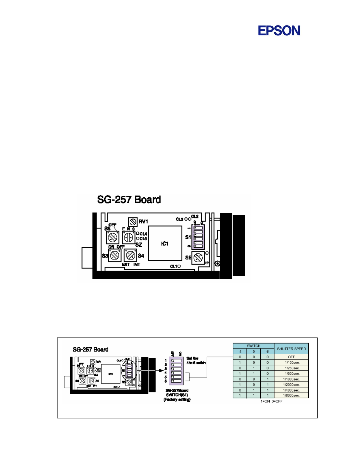
Configuring XC55 shutter speed for continuous mode
When using the XC55 in continuous mode, you can adjust the shutter speed using DIP
switch S1 as shown below.
EPSON RC+ 3.5.0 Release Notes Page 3 of 7 9/6/2002
Page 4

Seiko Epson Corporation
Factory Automation / Robotics
Conveyor Tracking Notes
The following notes are in addition to the information found in the Conveyor Tracking
chapter of the EPSON RC+ User's Guide.
Cnv_AbortTrack and Cnv_Fine not supported in this release
The Cnv_AbortTrack and Cnv_Fine commands are not supported. An error will occur at
compile time. These commands will be supported in a future release.
Asynchronous reset cameras should be used with high speed
conveyors
When using high-speed conveyors with vision, it is recommended that you use
asynchronous reset cameras and strobe the encoder board and vision trigger. If using
multiple asynchronous reset cameras, you must use ZeroFlg to lock the vision system
until the picture is acquired.
For example:
AccessVision ' This routine uses ZeroFlg to lock vision resource
VRun FindPart
On strobe, .2
Do
VGet FindPart.AcquireState, state
Loop Until state = 3
ReleaseVision
Verifying new encoder operation
After wiring one or more new encoders, follow these steps to verify operation.
1. Start RC+.
2. From the Setup | System Configuration | Encoders tab, add an encoder for each
encoder that was wired and click OK.
3. Create a new project called TestCnv.
4. From Tools | Conveyor Tracking, add a new sensor conveyor for each encoder.
Make sure that conveyor 1 uses encoder 1, conveyor 2 uses encoder 2, etc.
5. Now you can use the Cnv_Pulse function to read pulses from each encoder from a
program or from the monitor window.
EPSON RC+ 3.5.0 Release Notes Page 4 of 7 9/6/2002
Page 5

Seiko Epson Corporation
Factory Automation / Robotics
For example, execute this print statement from the monitor window to read the pulses
from encoder 1.
>? cnv_pulse(1)
Or you can write a program:
Function main
Do
Print Cnv_Pulse(1)
Wait .5
Loop
Fend
Vision conveyor calibration
When calibrating a vision conveyor, it is important that the vision sequence steps
correlate with the parts you are teaching in the correct order. This allows the system to
determine the conveyor camera orientation.
The calibration sequence must find two of the parts used for calibration. When using a
simple sequence that uses one object for each part, the first object of the sequence must
be taught by the robot as part 1. The second object of the sequence must be taught by the
robot as part 2.
The two parts can be anywhere in the field of view. However, to make it as easy as
possible for operators to calibrate the conveyor, the parts that will be found in the vision
sequence should be located such that part 2 is after part 1 in the direction of part flow. In
the figure below, object 1 in the vision sequence is Corr01, which locates Part 1. Object
2 is Corr02, which locates Part 2.
Vision Search Area
Part 2
Part Flow
Conveyor
Part 1
EPSON RC+ 3.5.0 Release Notes Page 5 of 7 9/6/2002
Page 6

Seiko Epson Corporation
Factory Automation / Robotics
If the vision sequence used to locate the parts is more complex, then the last two objects
of the sequence must have the location for parts 1 and 2. The object that finds part 1
must be the second to last object. The object that finds part 2 must be the last object. For
example, the following sequence uses two Point objects for the locations of part 1 and
part 2. Step 5 locates part 1 and step 6 locates part 2.
Step Object Type Description
1 Corr01 Correlation Locates feature on part 1
2 Frame01 Frame Single point frame using Corr01 as origin
3 Corr02 Correlation Locates feature on part 2
4 Frame02 Frame Single point frame using Corr02 as origin
5 Point01 Point Point in Frame01 that locates part 1.
6 Point02 Point Point in Frame02 that locates part 2.
EPSON RC+ 3.5.0 Release Notes Page 6 of 7 9/6/2002
Page 7

Seiko Epson Corporation
Factory Automation / Robotics
Known Problems
Setting Blob NumberToFind to 0 causes wrong Camera and
Robot coordinates
If NumberToFind is set to 0 for a Blob object (to find all occurrences), then Camera X, Y,
U and Robot X, Y, U values will be zero if the object is used in a sequence with
calibration. To workaround, set NumberToFind to a value greater than 0.
FmtStr incorrectly adds CR to end of destination string
When a string is formatted using FmtStr, a CR is appended to the end of the destination
string. To workaround, you can remove the CR using the Left$ function.
FmtStr "1.234", "0.0", a$
a$ = Left$(a$, Len(a$) - 1)
Help for Cnv_Point does not work with F1 key
If the program editor caret is in the Cnv_Point keyword, pressing F1 will display a "topic
not found" error. To view help for Cnv_Point, use the Index tab from Help, as shown
below.
EPSON RC+ 3.5.0 Release Notes Page 7 of 7 9/6/2002
 Loading...