

Page 1
Download Service Manual And Resetter Printer at http://printer1.blogspot.com
SERVICE MANUAL
Color Inkjet Printer
EPSON Stylus Photo R1800/R2400
SEIJ04015
Page 2

Notice:
All rights reserved. No part of this manual may be reproduced, stored in a retrieval system, or transmitted in any form or by any means, electronic,
mechanical, photocopying, recording, or otherwise, without the prior written permission of SEIKO EPSON CORPORATION.
The contents of this manual are subject to change without notice.
All effort have been made to ensure the accuracy of the contents of this manual. However, should any errors be detected, SEIKO EPSON would greatly
appreciate being informed of them.
The above not withstanding SEIKO EPSON CORPORATION can assume no responsibility for any errors in this manual or the consequences thereof.
EPSON is a registered trademark of SEIKO EPSON CORPORATION.
General Notice: Other product names used herein are for identification purpose only and may be trademarks or registered trademarks of their
respective owners. EPSON disclaims any and all rights in those marks.
Copyright © 2005 SEIKO EPSON CORPORATION.
I&I CS/Quality Management & PL Department
Page 3

PRECAUTIONS
Precautionary notations throughout the text are categorized relative to 1)Personal injury and 2) damage to equipment.
DANGER Signals a precaution which, if ignored, could result in serious or fatal personal injury. Great caution should be exercised in performing
procedures preceded by DANGER Headings.
WARNING Signals a precaution which, if ignored, could result in damage to equipment.
The precautionary measures itemized below should always be observed when performing repair/maintenance procedures.
DANGER
1. ALWAYS DISCONNECT THE PRODUCT FROM THE POWER SOURCE AND PERIPHERAL DEVICES PERFORMING ANY MAINTENANCE OR REPAIR
PROCEDURES.
2. NO WORK SHOULD BE PERFORMED ON THE UNIT BY PERSONS UNFAMILIAR WITH BASIC SAFETY MEASURES AS DICTATED FOR ALL
ELECTRONICS TECHNICIANS IN THEIR LINE OF WORK.
3. WHEN PERFORMING TESTING AS DICTATED WITHIN THIS MANUAL, DO NOT CONNECT THE UNIT TO A POWER SOURCE UNTIL INSTRUCTED TO
DO SO. WHEN THE POWER SUPPLY CABLE MUST BE CONNECTED, USE EXTREME CAUTION IN WORKING ON POWER SUPPLY AND OTHER
ELECTRONIC COMPONENTS.
WARNING
1. REPAIRS ON EPSON PRODUCT SHOULD BE PERFORMED ONLY BY AN EPSON CERTIFIED REPAIR TECHNICIAN.
2. MAKE CERTAIN THAT THE SOURCE VOLTAGES IS THE SAME AS THE RATED VOLTAGE, LISTED ON THE SERIAL NUMBER/RATING PLATE. IF THE
EPSON PRODUCT HAS A PRIMARY AC RATING DIFFERENT FROM AVAILABLE POWER SOURCE, DO NOT CONNECT IT TO THE POWER SOURCE.
3. ALWAYS VERIFY THAT THE EPSON PRODUCT HAS BEEN DISCONNECTED FROM THE POWER SOURCE BEFORE REMOVING OR REPLACING
PRINTED CIRCUIT BOARDS AND/OR INDIVIDUAL CHIPS.
4. IN ORDER TO PROTECT SENSITIVE MICROPROCESSORS AND CIRCUITRY, USE STATIC DISCHARGE EQUIPMENT, SUCH AS ANTI-STATIC WRIST
STRAPS, WHEN ACCESSING INTERNAL COMPONENTS.
5. REPLACE MALFUNCTIONING COMPONENTS ONLY WITH THOSE COMPONENTS BY THE MANUFAC TURE; INTRODUCTION OF SECOND-SOURCE
ICs OR OTHER NON-APPROVED COMPONENTS MAY DAMAGE THE PRODUCT AND VOID ANY APPLICABLE EPSON WARRANTY.
Page 4
About This Manual
This manual describes basic functions, theory of electrical and mechanical operations, maintenance and repair procedures of the printer. The instructions and
procedures included herein are intended for the experienced repair technicians, and attention should be given to the precautions on the preceding page.
Manual Configuration
This manual consists of six chapters and Appendix.
CHAPTER 1.PRODUCT DESCRIPTIONS
Provides a general overview and specifications of the product.
CHAPTER 2.OPERATING PRINCIPLES
Describes the theory of electrical and mechanical operations of
the product.
CHAPTER 3.TROUBLESHOOTING
Describes the step-by-step procedures for the troubleshooting.
CHAPTER 4.DISASSEMBLY / ASSEMBLY
Describes the step-by-step procedures for disassembling and
assembling the product.
CHAPTER 5.ADJUSTMENT
Provides Epson-approved methods for adjustment.
CHAPTER 6.MAINTENANCE
Provides preventive maintenance procedures and the lists of
Epson-approved lubricants and adhesives required for servicing
the product.
APPENDIX Provides the following additional information for reference:
• Connector pin assignments
• Exploded diagram & Parts List
• Electric circuit boards components layout
• Electrical circuit boards schematics
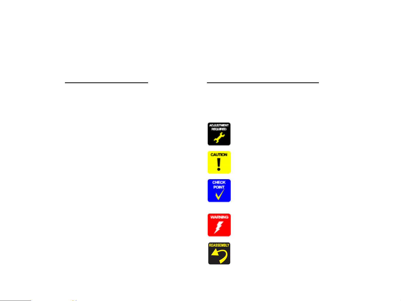
Symbols Used in this Manual
Various symbols are used throughout this manual either to provide additional
information on a specific topic or to warn of possible danger present during a
procedure or an action. Be aware of all symbols when they are used, and
always read NOTE, CAUTION, or WARNING messages.
Indicates an operating or maintenance procedure, practice or
condition that is necessary to keep the product’s quality.
Indicates an operating or maintenance procedure, practice, or
condition that, if not strictly observed, could result in damage to,
or destruction of, equipment.
May indicate an operating or maintenance procedure, practice or
condition th at is necess ary t o acco mplis h a t ask eff icie ntly . It may
also provide additional information that is related to a specific
subject, or comment on the results achieved through a previous
action.
Indicates an operating or maintenance procedure, practice or
condition that, if not strictly observed, could result in injury or loss
of life.
Indicates that a particular task must be carried out according to a
certain standard after disassembly and before re-assembly,
otherwise the quality of the components in question may be
adversely affected.
Page 5

Revision Status
Revision Date of Issue Description
A January 21, 2005 First Release
B March 31, 2005 Revised Contents
8. Stylus Photo R2400 (p198)
• Stylus Photo specific information is added.
5.2.5.1 Printing Calibration Chart by Users (p165)
• Descriptions of the procedure are added.
5.2.5.2 Writing of Color ID by Users (p169)
• A caution is deleted.
Color Correction Value Entry Procedure (p170)
• Supported OS and ports are added.
Calibration Chart Print Procedure for Users (p166)
• Descriptions of the procedure are added.
Page 6

EPSON Stylus Photo R1800/R2400 Revision B
CONTENTS
Chapter 1 Product Description
1.1 Overview.................................................................................................. 9
1.2 PG Setting ............................................................................................. 10
1.3 Functions .............................................................................................. 11
1.3.1 Control Panel ................................................................................ 11
1.3.2 Switches .................... ....... ...... ....... ...... ....... ...... ....... ...... ....... ......... 11
1.3.3 Indicators ................... ....... ...... ....... ...... ....... ...... ....... ...... ....... ...... ... 11
1.3.4 Switch Functions ........................................................... ....... ......... 11
1.3.5 Indicator Display in Normal Mode ................................................. 12
1.3.6 Error Status ................................................................................... 13
1.4 Casing Specifications .......................................................................... 14
1.5 Accessories .......................................................................................... 14
Chapter 2 Operating Principles
2.1 Overview................................................................................................ 16
2.2 Printer Mechanism ............................................................................... 16
2.2.1 Carriage Mechanism ..................................................... ....... ...... ... 17
2.2.2 Printhead Specificatio ns ... ...... ....... ...... ....... ...... ............................. 20
2.2.3 Paper Feeding Mechanism ................. ....... ...... ....... ...... ....... ...... ... 20
2.2.4 Paper Feeding Mechanism ................. ....... ...... ....... ...... ....... ...... ... 25
2.2.5 Ink System Mechanism ................................................................. 26
2.2.6 Ink Sequence ................................................................................ 28
2.2.7 Power-On Sequence ..................................................................... 30
2.3 Electrical Circuit Operating Principles............................................... 31
2.3.1 Power Supply Circuit Operating Principle ..................................... 32
2.3.2 C589 MAIN Circuit Operating Principle ......................................... 33
Chapter 4 Disassembly And Assembly
4.1 Overview ............................................................................................... 69
4.1.1 Precautions ................................................................................... 69
4.1.2 Tools ............................................................................................. 70
4.1.3 Screws .......................................................................................... 71
4.1.4 Work Completion Checklist ........................................................... 72
4.2 Disassembly ......................................................................................... 73
4.2.1 Removing the Housings ................................................................ 74
4.2.2 Waste Ink Pad ............................................................................... 80
4.2.3 Front Paper Guide Pad ................................................................. 82
4.2.4 ASF Assy ...................................................................................... 83
4.2.5 Removing the Boards ................................................................... 87
4.2.6 Disassembling the Printer Mechanism .......................................... 89
4.2.7 Removing the Motors .................................................................. 122
4.2.8 Removing the Sensors ................................................................ 124
Chapter 5 Adjustment
5.1 Adjustment Items and Overview....................................................... 129
5.1.1 Servicing Adjustment Item List .................................................... 129
5.1.2 Replacement Part-Based Adjustment Priorities .......................... 133
5.1.3 Required Adjustment Tools ......................................................... 136
5.2 Adjustment.......................................................................................... 137
5.2.1 PF Belt Tension Adjustment ....................................................... 137
5.2.2 PG Adjustment ............................................................................ 139
5.2.3 PF Roller Shaft Center Support Position Adjustment ................. 143
5.2.4 Colorimetric Calibration ............................................................... 147
5.2.5 Colorimetric Calibration by Users ............................................... 165
Chapter 3 Troubleshooting
3.1 Overview................................................................................................ 36
3.1.1 Troubleshooting according to Panel Messages ............................ 36
3.1.2 Troubleshooting based on Observed Faul ts ........................ ...... ... 59
Chapter 6 Maintenance
6.1 Overview ............................................................................................. 173
6.1.1 ROM Replacement ..................................................................... 173
6.1.2 Cleaning ...................................................................................... 173
6.1.3 Service Maintenance .................................................................. 174
6
Page 7

EPSON Stylus Photo R1800/R2400 Revision B
6.1.4 Lubrication ................................................................................... 175
Chapter 7 Appendix
7.1 Connector Summary .......................................................................... 182
7.1.1 Connectors and Pin Layouts ....................................................... 182
7.2 Exploded Diagram.............................................................................. 183
7.3 Parts List for EPSON Stylus Photo R1800 ....................................... 190
7.4 Circuit Diagram................................................................................... 192
Chapter 8 Stylus Photo R2400
8.1 Overview.............................................................................................. 199
8.1.1 Overview ............. ....................................... ...... ....... ...... ....... ...... . 199
8.1.2 Indicator Display in Normal Mode ............................................... 200
8.1.3 Error Status ................................................................................. 201
8.2 Casing Specifications ........................................................................ 202
8.3 Accessories ........................................................................................ 202
8.3.1 Printhead Specificatio ns ... ...... ....... ...... ....... ...... ........................... 203
8.3.2 Ink Sequence .............................................................................. 203
8.4 Overview.............................................................................................. 204
8.4.1 Troubleshooting according to Panel Messages .......................... 204
8.5 Parts List for EPSON Stylus Photo R2400 ....................................... 227
7
Page 8

PRODUCT DESCRIPTION
CHAPTER
1
Page 9
EPSON Stylus Photo R1800/R2400 Revision B
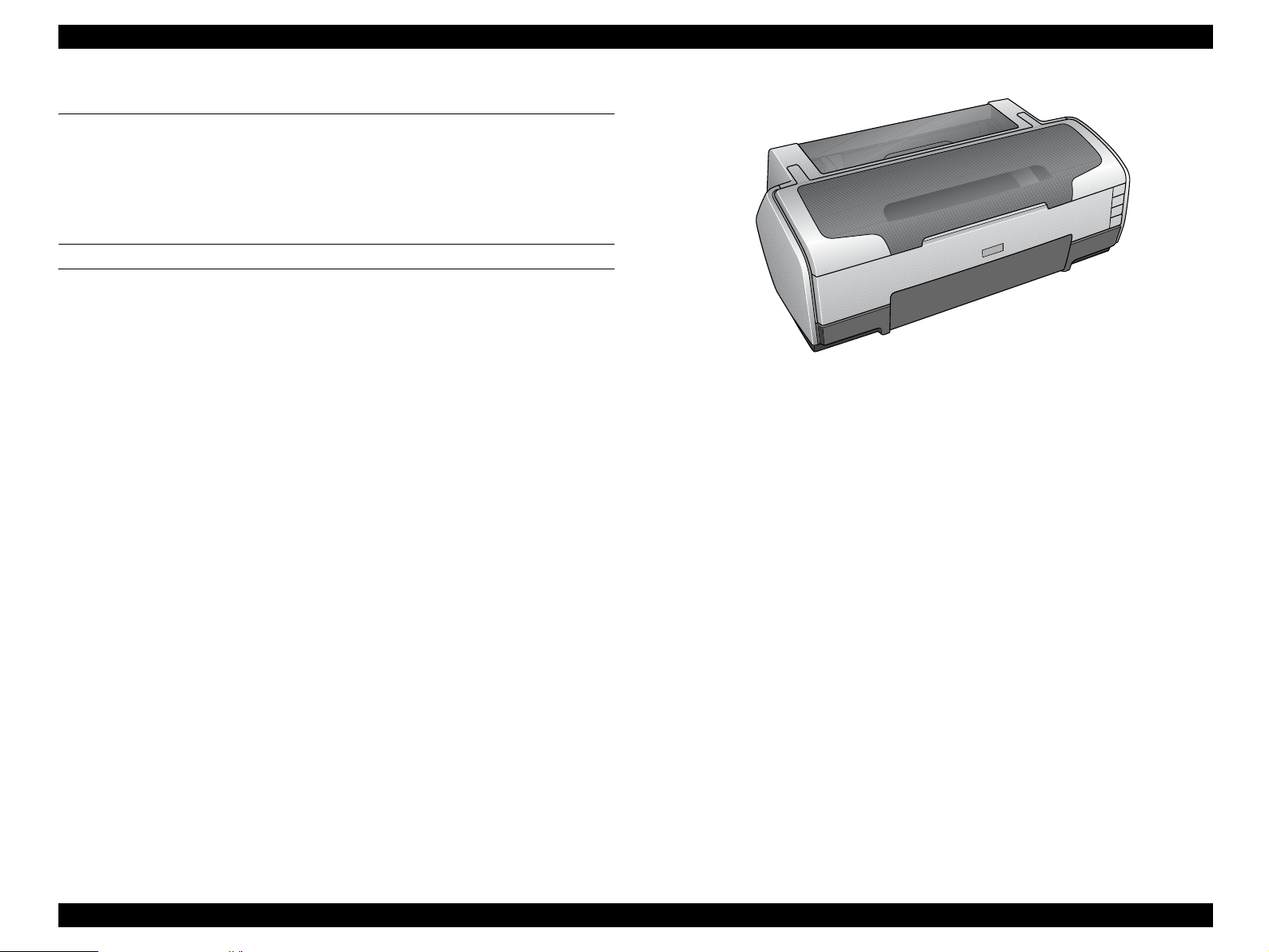
1.1 Overview
The Stylus Photo R1800 is a photo printer designed for a wide range of users
from individual users to commercial users. As a successor to the Stylus Photo
2100/2200, this consumer middle high model is capable of CD-R/DVD-R
printing and roll paper cutter functions.
This product has the following features.
FEATURES
High color print quality
5760 (H) x 1440 (V) dpi printing (Max resolution)
8 color printing
(PPI Black, Photo Black, Cyan, Magenta, Yellow, Red, Violet, Clear)
Pigment Ink supported
Separate Ink Cartridge for each color
Built-in 2 I/F
USB 2.0 (HS compatibility)
IEEE 1394
Figure 1-1. Product Appearance
Windows/Macintosh exclusive
Roll Paper Support
Printable area expand (Bottom margin reduce)
Card printing support
CD-R printing support
Product Description Overview 9
Page 10

EPSON Stylus Photo R1800/R2400 Revision B
1.2 PG Setting
As this printer uses an Auto PG (APG), an appropriate PG position is set according to the used paper type.
The following table indicates the PG positions, the main applications of each position, and the relationships between the two sensors used with the APG.
Table 1-1.
Application
Printing • PGPP
•A3
•A4
Non-printing
PG value 1.15mm 1.3mm 1.7mm 2.1mm 4.5mm –
Sensor PG (– –) PG (–) PG (Typ) PG (+) PG (++) Release
APG Sensor 1 OFF OFF OFF OFF OFF OFF
APG Sensor 2 ON ON ON ON OFF OFF
PG (– –) PG (–) PG (Typ) PG (+) PG (++) Release
• Exclusive paper • Plain paper
• Photo Album paper
• Photo Matte paper A3
fine
• PG (-) rub avoidance
• Standby position after
power-on (For bottom
stacker)
– –
• At power-off
• The Ink Mark Sensor
operates. (Auto Bi-D,
Detection of dot
missing)
PG Position
• Envelope
• PG (Typ) rub
avoidance
• CD-R
• Photo stand paper
–
• Initialization at power-
on
• Cleaning (wiping)
–
• Replace the Ink
Cartridge
• Waiting for CD-R/
Board paper to be fed
• Paper jam removal
Product Description PG Setting 10
Page 11
EPSON Stylus Photo R1800/R2400 Revision B
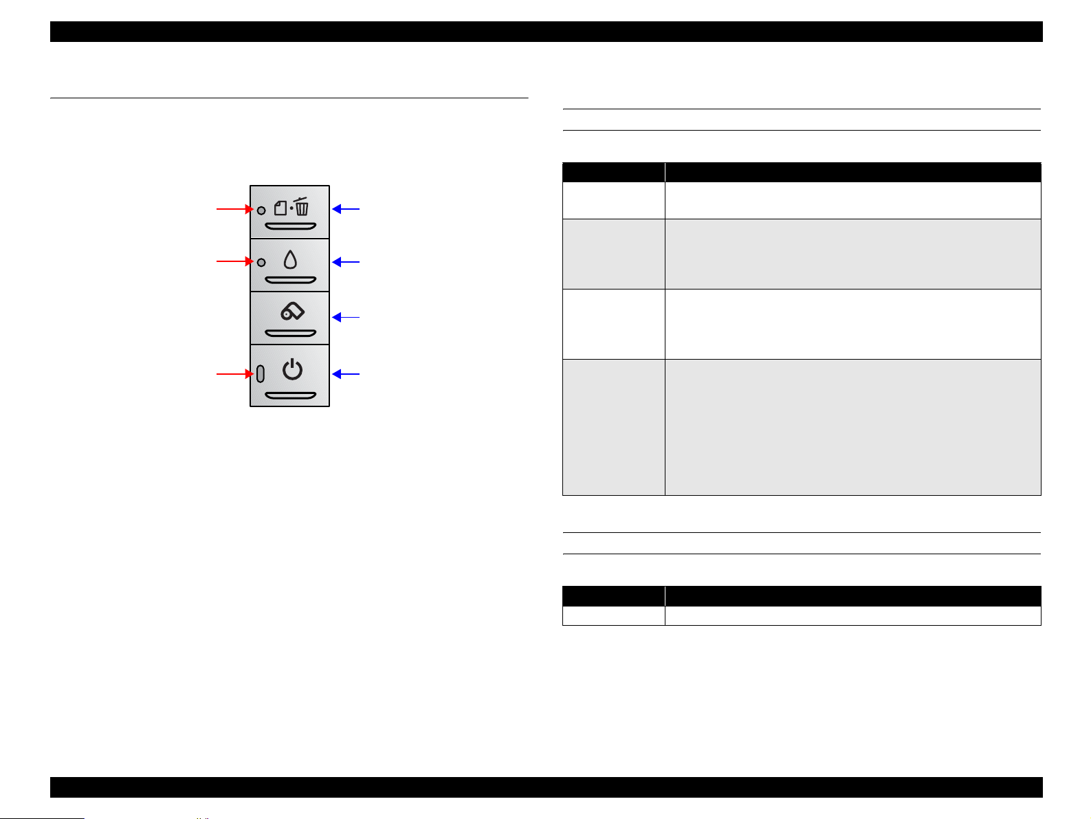
1.3 Functions
1.3.1 Control Panel
The appearance of the control panel is shown below.
Paper LED
Ink LED
Power LED
Figure 1-2. Control Panel Appearance
1.3.2 Switches
Power switch
Paper switch
Ink switch
Roll paper switch
Power switch
1.3.4 Switch Functions
FUNCTIONS IN NORMAL STATUS
Table 1-2. Normal-status Functions
Switch Function
Power switch
Paper switch
Ink switch
Roll paper
switch
• Power On / Off.
• Panel reset (off and on within 10 seconds).
• Loads or Ejects the P aper.
• When carriage is on the Ink Cartridge change position, return
carriage from Ink Cartridge change position.
• In the condition of printing, cancel the print job.
• Starts the Cleaning of head with 3 second pushing.
• Moves the carriage to cartridge change position.
• When carriage is on the ink c hange p ositio n, return c arriage from
Ink Cartridge change position.
• Loads the Roll paper.
• Back out the roll paper with 3 second pushing.
• Move to tear off position / Return from tear off position.
• When cartridge is on the Ink Cartridge change position, return
carriage from Ink Cartridge change position.
• When the photo album is used, ejects the paper forwards only.
(At this mode, the printer can’t move backwards without Top of
Form.)
Paper switch
Ink switch
Roll paper switch
1.3.3 Indicators
Power LED : Green
FUNCTION AT POWER-ON
Table 1-3. Power-on Function
Switch Function
Paper switch Starts stat us printings.
Note "*1": Status printings prints firmware version, ink counter and nozzle check
patterns.
*1
Paper LED : Red
Ink LED : Red
Product Description Functions 11
Page 12

EPSON Stylus Photo R1800/R2400 Revision B
1.3.5 Indicator Display in Normal Mode
Table 1-4. Printer Condition and LED Status
Printer status Error status
Idle – On – – 20
Data processing – Blink – – 19
*1
Pause
Ink sequence processing – Blink – – 17
Ink cartridge change mode – Blink – – 16
Ink low (warning) – – – Blink 15
Tear off status 11h – – – 14
Paper mismatch Error 0Ch – Fast Blink – 12
Paper Out 06h – On – 11
Ink end 05h – – On 10
No Ink cartridge or
Ink cartridge error
Paper Jam Error 04h – Blink – 8
Card loading error 2Ah – Blink 2 – 7
Cover Open Tray Error 2Bh – Fast Blink Blink 2 13
Reset input – On On On –
Fatal error 00h Off Fast Blink Fast Blink 4
Maintenance request 10h Off
Power off – Fast Blink Off Off 1
Note: • "–" : Don't care
• Blink : 0.5sec on + 0.5sec off repetition
• Blink 2 : 0.2sec on + 0.2sec + 0.2sec on + 0.4sec off repetition
• Fast Blink : 0.1sec on + 0.1sec off repetit ion
• Blink alternately 1 : 0.5sec on + 0.5sec off repetition
• Blink alternately 2 : 0.5sec off + 0.5sec on repetition
Status 05h – – – 18
05h
Power Paper Ink Priority
––On9
Indicators
Blink
alternately 1
Blink
alternately 2
2
Note"*1": When the Photo album paper is end, the printer goes to this status.
Product Description Functions 12
Page 13

EPSON Stylus Photo R1800/R2400 Revision B
1.3.6 Error Status
If any of the following states is detected, this printer is put in an error status and
turns the interface signal -ERROR "Low" and BUSY "High" to inhibit data input.
At this time, the printer is automatically disabled from printing. However, when
communication is being made using the IEEE1284.4 protocol, communication
with the printer is enabled.
General error
After the cause of this type of error is removed, the printer can resume its
operation from where it stopped due to the error
Table 1-5. General error
Error Status Occurring Condition Resuming Condition
Cover open (tray)
error
Paper mismatch
error
Paper out When printer fails to load a sheet, it
Ink out When the printer runs out the most
No ink-cartridge When printer detects that ink-
When the front cover is opened at
ASF, roll paper or photo album
printing mode, the printer goes this
error.
If the paper path specified by the
print data is different from the
printer’s real paper path, the printer
goes to this error.
goes paper out error.
part of the ink of any one color, it
warns ink-low and keeps printing.
When the printer runs out the whole
ink of any one color, it stops printing
and indicates ink-out error.
cartridge comes off, it goes this error
mode.
Close the front cover.
Change the printer’s
paper path to the one
specified by the data.
Set the paper to the ASF
and push the Paper
switch.
Install the new Ink
Cartridge.
Install the new Ink
Cartridge.
Table 1-5. General error
Error Status Occurring Condition Resuming Condition
Paper jam • Failure of ejecting a sheet
• Failure of loading a sheet to the
loading position
Card loading error When the card was loaded to the
wrong position, the printer goes this
error.
Remove the jammed
paper.
Set an A4 paper to the
ASF, and press the
paper switch.
If the card couldn’t eject
at your first try, repeat
again the same method.
Fatal error
After the cause of this type of error is removed, the printer cannot return to
normal unless it is powered off and then on again
Table 1-6. Fatal error
Error Status Occurring Condition Resuming Condition
Maintenance
request
Fatal errors • CR motor control error
When the total quantity of ink wast ed
through the cleanings and flushing is
reaches to the limit, printer indicates
this error and stops.
• PF motor control error
• ASF motor control error
• Auto Platen Gap control error
• Head temperature error
• PW sensor error
Replace the absorber in
the printer enclosure by a
service person.
Turn off and turn on.
Product Description Functions 13
Page 14
EPSON Stylus Photo R1800/R2400 Revision B
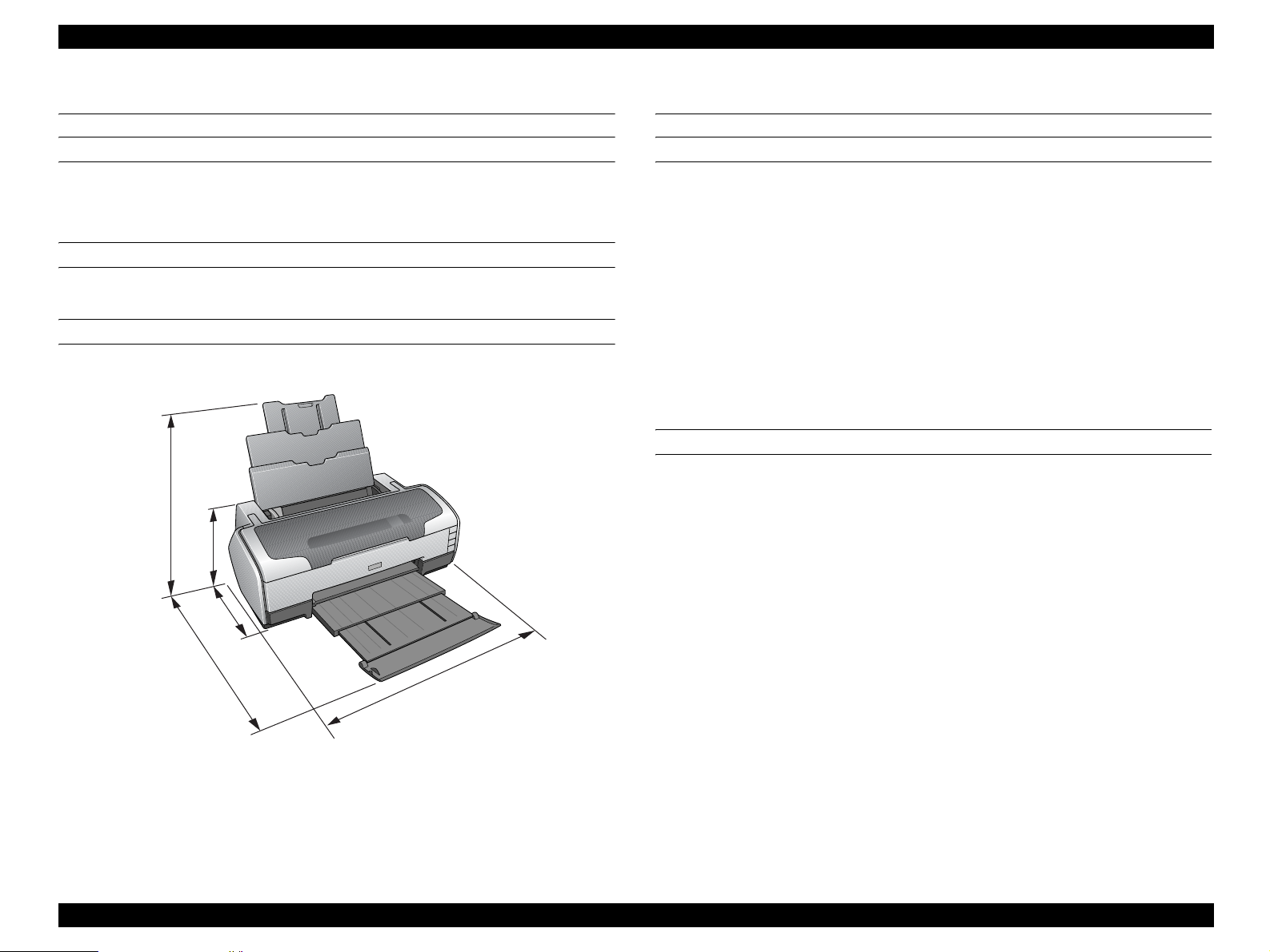
1.4 Casing Specifications
EXTERNAL DIMENSIONS
When tucked : 615 (width) x 314 (depth) x 219 mm (height)
When used : 615 (width) x 453 (depth) x 737 mm (height)
WEIGHT
11.7 kg (without the Ink Cartridges, Roll paper holder and CD-Tray)
EXTERNAL DIMENSION DIAGRAM
737
219
314
453
615
1.5 Accessories
STANDARD ACCESSORIES
User’s guide
Ink Cartridge (one for each of 8 colors)
Setup Sheet
Power Cord
Software CD-ROM
CD-R Print Position Check sheet
Roll Paper Holder
8-cm CD/DVD adapter
CD/DVD tray
CONSUMABLES AND OPTIONS
Ink Cartridges
Gloss Optimizer : T0540
Black : T0541
Cyan : T0542
Magenta : T0543
Yellow : T0544
Red : T0547
Matte Black : T0548
Blue : T0549
802.11g Radio printing adapter : PA-W11G
Figure 1-3. External Dimension Diagram
Product Description Casing Specifications 14
Page 15

OPERATING PRINCIPLES
CHAPTER
2
Page 16
EPSON Stylus Photo R1800/R2400 Revision B
2.1 Overview
This chapter explains the operating principles of the mechanical sections and
electrical circuits in this product. The main components of this product are as
follows.
Control circuit board : C589 MAIN
Power supply circuit board : C589 PSB
Control panel board : C589 PNL
Control panel B board : C589 PNL-B
2.2 Printer Mechanism
Like the conventional model, this product uses DC motors and stepping motors
as power sources. The following table describes the motor types and their
applications.
Table 2-1. Motors
Motor Name Type Applications/Functions
Used for carriage driving. Makes little noise
during driving. The CR linear scale and CR
encoder sensor are used to control the motor.
Drives the Paper loading rollers at the time of
fixed-value paper loading or paper feed/eject
operation. To grasp the paper feed pitch, the
precision gear surface is fitt ed with th e PF sc ale
and the PF encoder sensor is used to control
the motor.
Drives the Carriage Unit at the time of PG
setting. The two APG Sensors and Carriage
Shaft are driven vertically to control the motor.
Drives the paper feed operation of the ASF.
Since this is a stepping motor, any scales or
photo sensors to know the driv ing conditions are
not required.
Drives the pump, wiper, etc. of the Ink System.
Since this is a stepping motor, any scales or
photo sensors to know the driv ing conditions are
not required.
CR Motor
PF Motor
APG Motor
ASF Motor
Pump Motor
DC motor with
brushes
DC motor with
brushes
DC motor with
brushes
4-phase, 48-pole
PM type
stepping motor
4-phase, 48-pole
PM type
stepping motor
The basic mechanism is almost same as the Stylus Photo R800.
The most major difference is that this Stylus Photo R1800 is equipped with a
dedicated sensor to detect a open or close status of the Front Cover.
This prevents the Print Head from damaging by mistake.
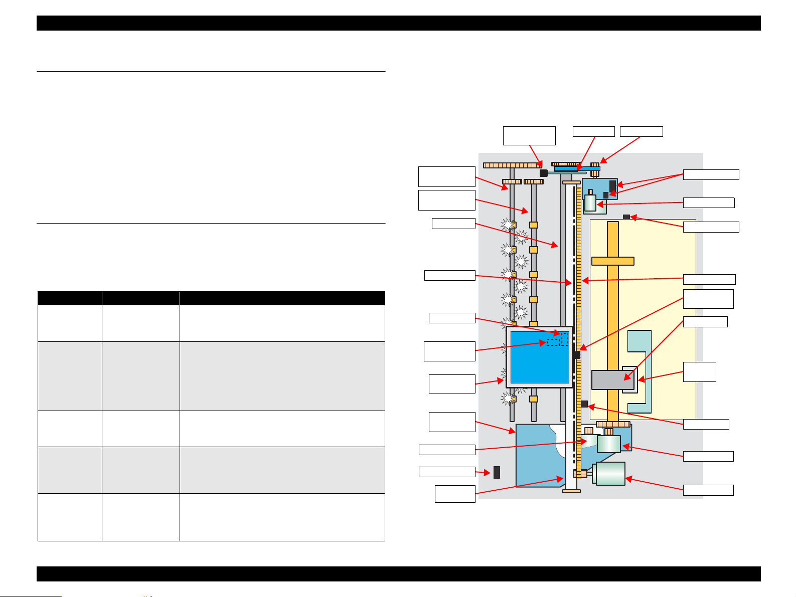
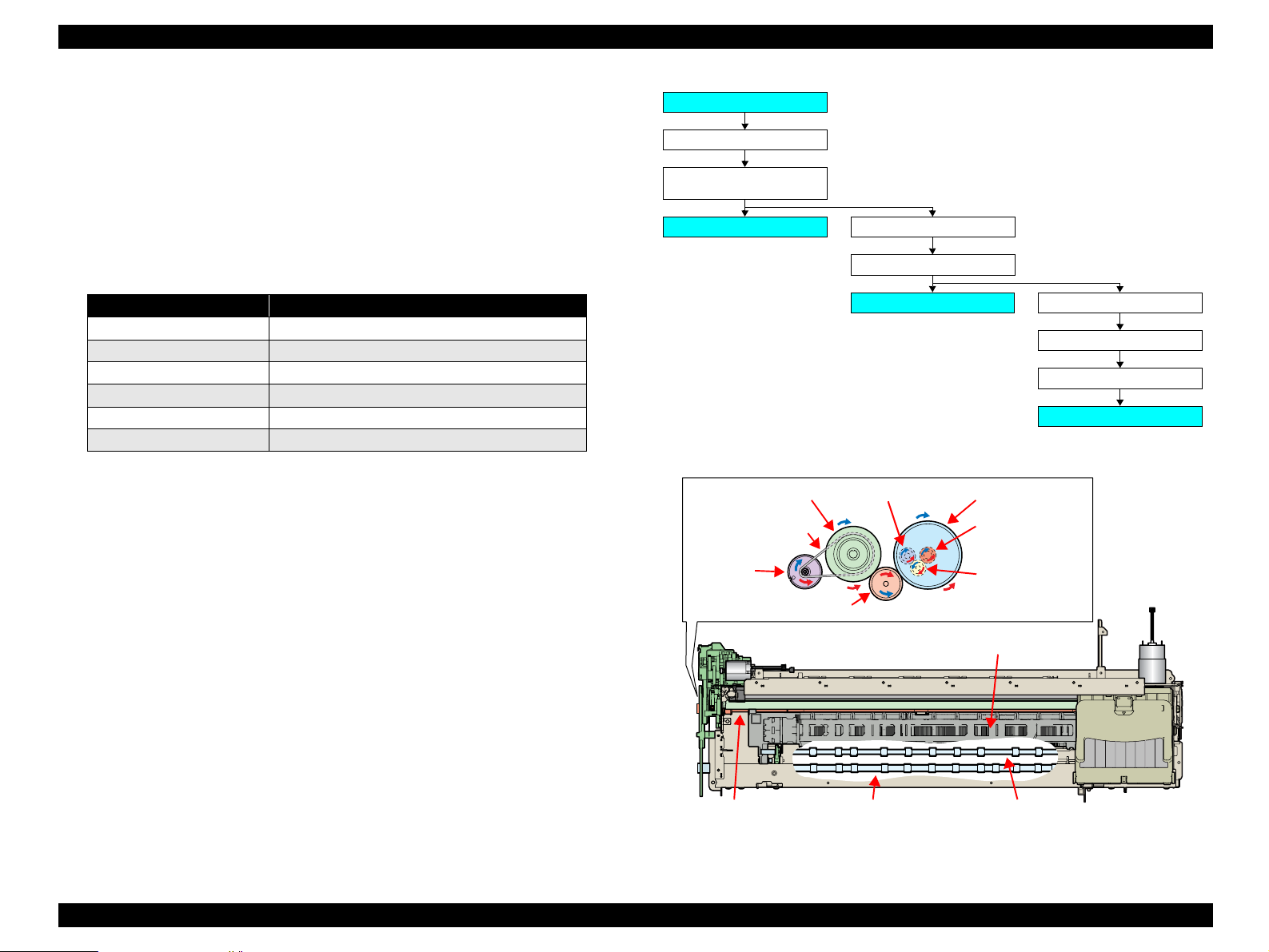
The schematic diagram below sho ws the pri nte r mecha nis m.
PF Encoder
Sensor
Front Paper
Eject Roller
Rear Paper
Eject Roller
PF Roller
CR Scale
PW Sensor
Ink Mark
Sensor
Carriage
Unit
Ink System
Unit
Pump Motor
CD-R Sensor
Carriage
Shaft
PF Scale
PF Motor
APG Sensors
APG Motor
APF Sensor
Timing Belt
CR Encoder
Sensor
LD Roller
Retard
Roller
PE Sensor
ASF Motor
CR Motor
Figure 2-1. Printer Mechanism Outline
Operating Principles Overview 16
Page 17

EPSON Stylus Photo R1800/R2400 Revision B
2.2.1 Carriage Mechanism
The Carriage mechanism consists of the Carriage Motor (CR Motor), Carriage
Shafts, Platen Gap Adjustment Mechanism, Carriage Lock Mechanism, and
others.
2.2.1.1 Carriage Mechanism
The following indicates the specifications of the CR motor (DC motor) that
drives the Carriage.
Table 2-2. CR Motor Specifications
Item Specifications
Type DC motor with brushes
Drive voltage +42V ± 5% (voltage applied to driver)
Armature resistance 29.2Ω ± 10%
Inductance 30.0mH ± 25%
Drive method PWM, constant-current chopping
Drive IC A6628
Closed loop control based on the CR Motor (DC Motor) and CR Encoder
Sensor has advantages in stabilized print quality and silent operation.
Heat Generation Control
The printer has a machanism to reduce the variations in the torque
constant and coil resistance of the DC motors, and variations in output
voltage of the Power Supply Board to obtain a designated heating value.
CR Variation Measurement Sequence
The variations mentioned above are measured in a CR variation
measurement sequence when the CR mechanical load is in the initial
status and saved into the EEPROM (A6<H>). According to the saved
information, the printer controls the drive voltage to obtain a designated
driving current. This minimizes the unit-to-unit variation.
CR Measurement Sequence
To set the appropriate drive current value according to the CR mechanical
load, the mechanical load is measured in a CR measurement sequence
and saved into the EEPROM A4<H>, A5<H> at power-on or after
replacement of the Ink Cartridge (s). However, if 6E is saved at the
EEPROM A4<H> and 05 at A5<H>, Fatal error will occur since too large
load is applied to the CR drive system.
The above control and sequences correct the drive current value of the CR
Motor according to not only the mechanical load but also the variations of the
motor and like. In addition, the resultant CR drive current value is used to
calculate a heating value, and when the specified heating value is reached,
wait time is provided per CR path for printing.
Operating Principles Printer Mechanism 17
Page 18

EPSON Stylus Photo R1800/R2400 Revision B
2.2.1.2 Carriage Home Position Detection
As in the conventional model, the Carriage Home Position is detected using the
drive current of the CR Motor and the speed/position signal of the CR Linear
Encoder.
The basic home position detection sequence is as described below.
1. The CR linear encoder pulse counter in the CPU is reset by the
initialization operation performed at power-on.
2. When the CR Motor rotates counterclockwise, the Carriage Unit moves
from left to right. When the following conditions are satisfied, the CPU
assumes that the Carriage Unit made contact with the right frame.
The ASIC detects 1158/1500 counts or more in the PWM output under
CR Motor load positioning control.
P1 (number of output pulses from when power is switched on until the
Carriage Unit makes contact with the right frame) is 19 steps or less.
3. When the CR Motor rotates clockwise, the Carriage Unit moves from right
to left. When the following conditions are satisfied, the CPU assumes that
the Carriage Unit reached the CR lock confirmation position.
The ASIC detects 575/1500 counts or more in the PWM output under
CR Motor load positioning control.
A difference between P1 and P2 (number of output pulses from when
the Carriage Unit made contact with the right frame until it reaches the
Carriage lo ck confirmation position) is 19 steps or less.
4. When the CR Motor rotates counterclockwise to move the Carriage from
left to right and the CPU detects 1158/1500 counts or more in the PWM
output under CR Motor load positioning control, the printer judges that the
Carriage moved to the far right position (is in contact with the right frame ).
5. When a difference between P1 and P3 (number of output pulses from
when the Carriage Unit reached the Carriage lock confirmation position
until it makes contact with the right frame) is 4 steps or less, the printer
judges that the Carriage Unit is in the home position.
The IC14 (ASIC) sets the drive current value adequate for the Carriage Unit
motion and outputs it to the motor driver.
Based on the signal output from the IC14 (ASIC), the IC5 (Motor Driver)
outputs the CR Motor drive current to the CR Motor.
2.2.1.3 Sequen ce Used for PW Detection
The PW (paper width detection) Sensor installed on the Carriage Unit bottom is
used to control the printer according to various sequences.
The following briefly describes the PW Sensor operating principle.
A dark voltage is measured by the PW Sensor in three places at the right flat
area (area without the absorber) on the Front Paper Guide every time the
printer is turned on, and the measurement values are saved into the EEPROM
as threshold values.
Threshold value detection voltage: Paper present
Threshold value detection voltage: Paper absent
The following sequences are performed.
Detection of Left and Right Edges of Paper and Control
Before Printing
The printer detects that paper has been loaded. And it sets the print
range according to the paper-size information from the Driver and the
actual paper-size detected by the PW sensor.
During Printing
When executing a borderless printing, the printer sets the off-range
margins by detecting the paper edges with the PW Sensor. And when
the resolution is 1440 x 1440 (VSD3) or 2880 x 1440 (VSD3) dpi, the
printer performs the Off-Range Thinning Out Control to make a further
correction to the off-range margins.
Detection of Top Edge of Paper and Control
Before starting a print job, the printer detects the top edge of a loaded
single sheet of paper, roll paper, or board paper to set the off-range top
margin. (Only when not detecting the top edge of paper with the PW
Sensor.)
Detection of Bottom Edge of Paper and Control
After starting a borderless printing, the printer sets the off-range bottom
margin.
Detection of Edges of CD-R and Control
Before starting to print, the PW Sensor detects top, bottom, left and right
edges of the CD-R. See Section 2.2.3.4 CD-R Printing Mechanism on
page 24.
Operating Principles Printer Mechanism 18
Page 19
EPSON Stylus Photo R1800/R2400 Revision B
PW sensor dark voltage (VH) measurement
PW sensor dark voltage (VH) measurement is performed at the following
timings and locations and used to calculate the threshold value of whether
paper is present or not.
Cut sheets, Roll paper
The dark voltage is measured and updated at every power-on, and the
threshold value (VS) is calculated and saved in the EPROM area as a
PW detection level.
• Threshold value detection voltage: Paper present
• Threshold value detection voltage: Paper absent
CD-R Tray
When printing on a CD-R, the dark voltage is measured on the CD-R
tray, and the threshold value (VS) is then calculated and saved in the
EPROM area as a PW detection level.
• Threshold value detection voltage: CD-R present
(tray home position detected)
The measurement voltage in the presence of the CD-R is saved into
the EEPROM as a white level. The white level value is used to check
the sensor deterioration condition during servicing or like.
• If the measurement value of the white level is close to that of the PW
detection level, it means that the sensor is dirty or deteriorated.
2.2.1.4 APG (Auto PG) Mechanism
The following indicates the specification of the DC motor that drives the APG.
Table 2-3. APG Motor Specifications
Item Specifications
Type DC motor with brushes
Drive voltage +42V ± 5% (voltage applied to driver)
Armature resistance 64.7Ω ± 15%
Inductance 37.6mH ± 25%
Drive method PWM, constant-current chopping
Drive IC A6628
The APG Motor (DC Motor) and two APG Sensors drive the PG Cam to
automatically adjust the PG amount according to the paper.
APG
Sensor
Carriage Shaft Carriage Unit
PG CamAPG Sensor
APG Motor
Figure 2-2. APG Mechanism
Operating Principles Printer Mechanism 19
Page 20
EPSON Stylus Photo R1800/R2400 Revision B
2.2.2 Printhead Specifications
The Printhead of this product is a F-Mach head.
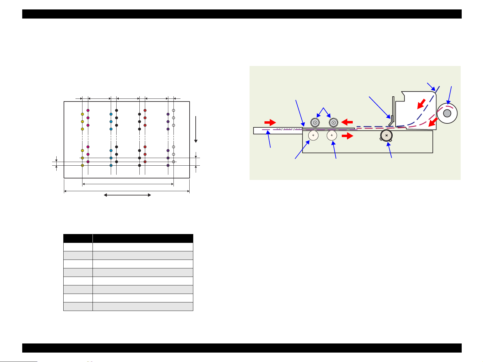
The following shows the arrangement of the nozzles and the color
arrangement of each nozzle line when viewed the Print Head from behind.
0.071mm
(1/360inch)
7.620mm
(216/720inch)
2.258mm
(64/720inch)
Line A
(64/720inch)
Line C
Line B
Carriage moving direction
Figure 2-3. Nozzle Arrangement
7.620mm
(216/720inch)
2.258mm
Line D
31.89mm
41.66mm
2.258mm
(64/720inch)
Line E
7.620mm
(216/720inch)
Line F
2.258mm
(64/720inch)
LineG
Paper feeding
direction
Line H
0.141mm
(1/180inch)
2.2.3 Paper Feeding Mechanism
The paper feeding mechanism is a mechanism that feeds paper or CD-R Tray
to the PF Roller Shaft.
CD-R Tray
Star Wheel Rollers
Board paper
Front Paper Eject Roller
Figure 2-4. Paper Feeding Mechanism
PE Sensor
Rear Paper Eject Roller
Cut sheet
PF Roller
Roll paper
Table 2-4. Nozzle Lines and the Corresponding Ink Color
Line Ink
AYellow
B Magenta
CCyan
D Matte-black
E Photo-black
F Red
GBlue
H Gloss Optimize r
Operating Principles Printer Mechanism 20
Page 21
EPSON Stylus Photo R1800/R2400 Revision B
2.2.3.1 ASF Paper Feeding Mechanism
The following shows the specifications of the stepping motor that drives the
ASF Assy.
Table 2-5. ASF Motor Specifications
Item Specifications
Type 4-phase, 48-pole PM type stepping motor
Drive voltage +42V ± 5% (voltage applied to driver)
Winding resistance 7.0Ω ± 10% (per phase at 25°C)
Inductance 10.2mH ± 20% (1kH, 1Vrms, 25Åé)
Drive method Bipolar drive/constant-current drive
Drive IC A6628
Driven by the ASF Motor, the ASF Assy performs the following feeding
operation.
1. When a paper feeding command is issued from the PC or the Paper Switch
of the panel is pressed after power-on, the driving force of the ASF Motor
begins to be transmitted to the LD Roller following the route shown below.
ASF Motor
Combination Gear 29, 11
4. When the next sheet of paper is fed by the LD Roller and the Retard Roller,
the Hopper is pressed against the Frame again by the Hopper Cams. And
the Paper Holder of the Paper Back Lever rises by the Cams at the left and
right ends of the LD Roller to prevent the next sheet from being fed with the
previous sheet.
5. The LD Roller stops to rotate when it makes one revolution and the Flag of
the ASF Sensor Wheel returns to the ASF Sensor.
LD Shaft Spur Gear
LD Roller
2. When the LD Roller starts rotating, the Flag of the ASF Sensor Wheel
comes free from the notch on the ASF Sensor. And at the same time, the
Paper Back Lever becomes free from the Cams located at the left and right
ends of the LD Roller, then the Paper Holder on the Paper Back Lever
inclines downward by tensile force of the Paper Back Lever Torsion Spring.
3. By the LD Roller's rotation, the Hopper is released from the Hopper Cams
located at the left and right ends of the LD Roller, and the Hopper pops up
by tensile force of the Hopper Compression Spring.
Operating Principles Printer Mechanism 21
Page 22
EPSON Stylus Photo R1800/R2400 Revision B
2.2.3.2 Roll Paper Feeding
Relay Board
Sensor
LD
Roller
Cam
ASF
ASF Sensor
Wheel
Hopper
LD Roller
Paper
Hopper
Compression
Spring
ASF Motor
LD Shaft
Spur Gear
Combination
Gear 29.11
When selecting the Roll Paper Mode, the contol Panel switches function in
different ways from when printing other than roll paper. This section describes
the deifference.
1. The roll peper is fed into the printer after a lapse of three seconds from
when the PE sensor detects the paper.
2. The roll paper is fed backward to be set at the print position.
While the printer is performing the above operation, the switches are disabled.
After the roll peper is set to the print position, the switches operation becomes
defferent from when printing other than roll paper.
The details of the difference are described below.
When Loading Roll Paper.
Pressing the Roll Paper Switch for more than 3 seconds feeds the leading
edge of the roll paper backward to the PE Sensor (the Paper LED flashes).
In this state, draw the roll paper and press the Paper Switch to return the
panel operation to the normal mode that enables paper feeding from the
ASF.
When Received a Print Job for Roll Paper
1. After finished the print job, press the Roll Paper Switch.
2. A cutoff line is printed, and the roll paper is fed to the roll paper cut
position.
3. After cutting the roll paper with a pair of scissors or like, press the
Roll Paper Switch again. This returns the leading edge of the
paper to the print starting position.
Retard
Roller
Standby State Feeding Paper
Paper Back Lever
Torsion Spring
Paper Back Lever
Figure 2-5. ASF Paper Feeding Mechanism
Operating Principles Printer Mechanism 22
Page 23
EPSON Stylus Photo R1800/R2400 Revision B
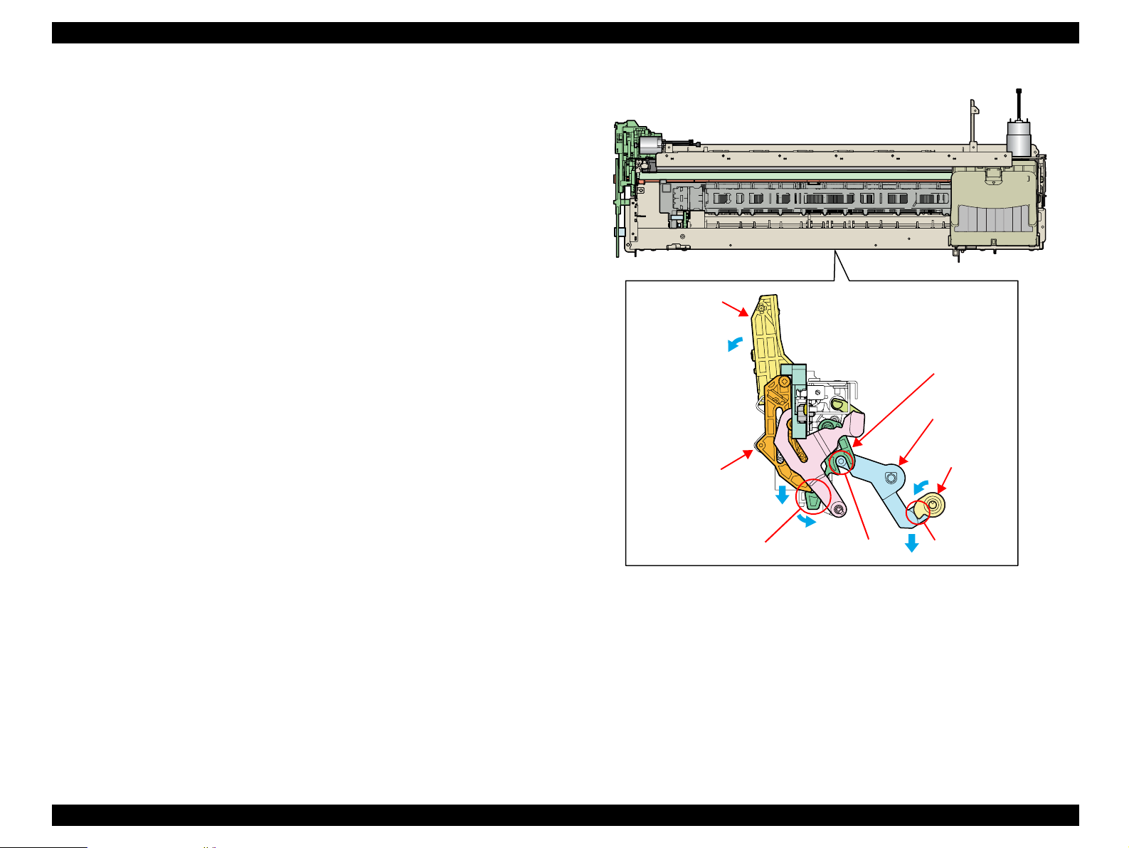
2.2.3.3 CD-R Tray Base Lock Mechanism
To prevent the Print Head from being damaged by mistake, the printer is
designed to lock the CD-R Tray Base when the Carriage Unit is out of its home
position.
The following explains the lock mechanism of the CD-R Tray Base.
Lock Release Sequence
1. When the Carriage Unit returns to its home position, the Pump
Motor drive is transmitted to the Paper EJ Lock Release Cam.
2. The salient of the Cam presses down the Paper EJ Transmission
Lock Lever to release the tab of the Paper EJ Lock Lever from the
Paper EJ Transmission Lock Lever.
3. The CD-R Release Lever comes free from the Paper EJ Lock
Lever and comes down to enable the CD-R Tray Base to open.
When the Carriage Unit is out of its home position, the salient of the Paper EJ
Lock Release Cam does not press down the Paper EJ Transmission Lock
Lever, and the tab of the Paper EJ Lock Lever is not released. Therefore, the
CD-R Tray Base cannot be opened.
CD-R Tray Base
Paper EJ
Lock Lever
Paper EJ
Transmission
Lock Lever
Paper EJ
Lock Release
Cam
CD-R Release Lever
Jointed positionTab
Salient
Figure 2-6. CD-R Tray Base Lock Mechanism
Operating Principles Printer Mechanism 23
Page 24
EPSON Stylus Photo R1800/R2400 Revision B
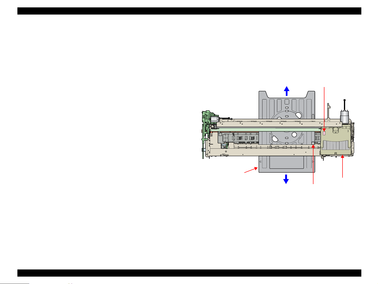
2.2.3.4 CD-R Printing Mechanism
CD-R Tray Home Position Detection Sequence
The following sequence is performed after opening the Front Cover (CD-R
Sensor closing), inserting the CD-R Tray to the specified position, and
pressing the Paper SW.
When the close signal of the CD-R Sensor is detected, no paper is fed
from the ASF if the Paper Switch is pressed. In this case, the Paper Switch
executes a CD-R Tray home position detection sequence.
1. When the APG Assy is driven, the PG position is set to "++" and
the Driven Roller of the Upper Paper Guide presses the CD-R
Tray.
2. When the Carriage Unit moves leftward and the PW Sensor
detects the CD-R, the Carriage Unit returns to its home position
(HP).
3. After waiting for about 5 seconds at the HP, the Carriage Unit
moves to the CD-R Tray HP detectable position (right end of the
CD-R Tray).
4. The CD-R Tray is pulled in the ASF direction, the PW Sensor
detects the CD-R Tray HP, and then the Carriage Unit moves to
the center of the CD-R Tray.
5. When the PW Sensor detects the white marking in the center of
the CD-R Tray, the CD-R Tray is fed in the paper ejection
direction.
6. The Carriage Unit moves leftward, the PW Sensor detects the left
side white marking, then the Carriage Unit moves rightward, and
the PW Sensor detects the right side white marking.
7. The Carriage Unit moves to the center of the CD-R Tray, and the
PW Sensor starts detection in the back-and-forth direction of the
CD-R. After the leading edge of the CD-R is detected, the CD-R
Tray is fed in the paper ejection direction, and the trailing edge of
the CD-R is detected. After that, the CD-R Tray is fed to the center
of the CD-R in the paper ejection direction.
8. The Carriage Unit moves leftward, and the PW Sensor starts
detection in the horizontal direction of the CD-R. After the left end
of the CD-R is detected, the Carriage Unit moves rightward, and
the right end of the CD-R is detected.
9. The Carriage Unit moves to the CD-R Tray HP detectable position
and stops there, and then the CD-R Tray is fed in the ASF
direction.
10. When the CD-R Tray stops operating, the Carriage Unit moves to
the carriage HP and stands by.
If the CD-R Tray HP, white marking or CD-R cannot be detected within the
steps predetermined for the CD-R Tray HP detection sequence, the CD-R Tray
is ejected and Paper Out Error is displayed.
PW Sensor
CD-R Tray
Carriage Unit
CD-R home position
Figure 2-7. CD-R Printing Mechanism
Operating Principles Printer Mechanism 24
Page 25
EPSON Stylus Photo R1800/R2400 Revision B
2.2.4 Paper Feeding Mechanism
The Paper Feeding Mechanism is designed to transfer the paper fed from the
ASF, Roll Paper Guide or Board Paper Guide or the CD-R fed from the CD-R
Tray according to the print data.
2.2.4.1 Paper Feeding Mechanism
The following shows the specifications of the DC motor that drives the Paper
Feeding Mechanism.
Table 2-6. PF Motor Specifications
Item Specifications
Type DC motor with brushes
Drive voltage +42V ± 5% (voltage applied to driver)
Armature resistance 21.2Ω ± 10%
Inductance 17.2mH (1kHz)
Drive method PWM
Drive IC A6628
Like the CR Motor, a DC motor is used as the PF Motor in this product.
Closed loop control based on the DC Motor and Rotary Encoder has the
following advantages.
Improved paper feed accuracy
Paper feed amount control
PF Motor
PF Timing Belt
Combination Gear
36.294, 45.5
PF Roller
Spur Gear 31.5
Spur Gear 68
Front Paper Ejec t Roller
Spur Gear 16; B (front)
Spur Gear 15.5
Spur Gear 16; B (rear)
Rear Paper Eject Roller
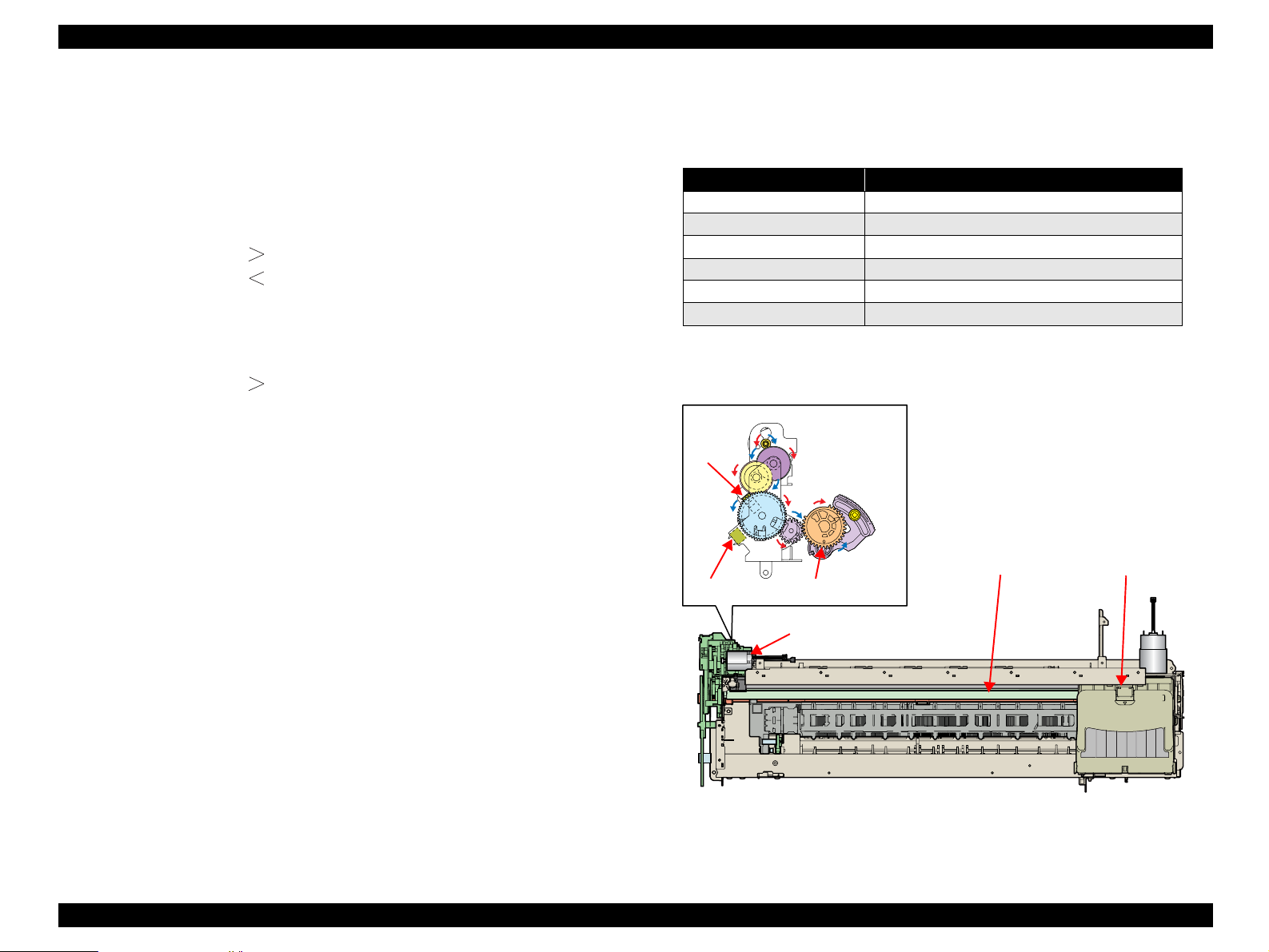
The following shows the part names and outline of the drive transmission path.
Combination Gear
36.294, 45.5
PF Timing Belt
PF Motor
Spur Gear 16; B (rear)
Spur Gear 68
Front Paper
Eject Roller
Spur Gear 15.5
Spur Gear 31.5
The PF Motor drive is transmitted to the PF Roller and the Paper EJ Roller
following the route shown below. The route is also followed by the paper.
PF Roller
Front Paper Eject Roller
Front Paper Guide
Rear Paper Eject Roller
Figure 2-8. Paper Feeding Mechanism
Operating Principles Printer Mechanism 25
Page 26
EPSON Stylus Photo R1800/R2400 Revision B
The fed paper is detected by the PE Sensor, and its leading edge is then
transferred to the front of the Front Paper Guide.
To eliminate the deflection of the paper, the paper is then returned toward the
ASF Assy by the specified number of steps according to the paper feed mode.
The paper is transferred again to the specified paper locating position of the
Front Paper Guide.
2.2.4.2 PF Measurement Sequence
The mechanical load in the paper feeding path is measured in the following
cases to perform control so that an adequate current value is set according
to the mechanical load.
When power is switched on
When the Ink Cartridge is replaced
When the mechanical load in the paper feeding path reaches the specified
value, a Fatal Error is displayed.
2.2.5 Ink System Mechanism
The Ink System Mechanism consists of the following units.
Pump Unit (including the CR Lock Lever)
Cap Unit
2.2.5.1 Pump Unit
The Pump Unit is designed to suck ink from the Print Head or Cap Unit. The
Cap Unit has a built-in Head Cleaning Wiper.
The following shows the specifications of the stepping motor that drives Pump
Unit.
Table 2-7. Pump Motor Specifications
Item Specifications
Type 4-phase, 48-pole PM type stepping motor
Drive voltage +42V ± 5% (voltage applied to driver)
Winding resistance 10.3Ω ± 10% (per phase at 25°C)
Inductance 13.4mH ± 20% (1kH,1Vrms)
Drive method Bipolar drive/constant-current drive
Drive IC A6628
The following operations are performed when the drive of the Pump Motor is
transmitted to the Pump Unit.
Table 2-8. Pump Motor Rotation Directions and Functions
Pump Motor Rotation Direction* Functions
•Cap closing
CW direction
CCW direction
Note "*": The direction (CW or CCW) was determined viewing the motor from the
output shaft of the motor mounting plate.
• Ink suction
• Wiper resetting
• CR Lock setting
• Cap opening
• Pump release
• Wiper setting
• CR Lock resetting
Operating Principles Printer Mechanism 26
Page 27
EPSON Stylus Photo R1800/R2400 Revision B
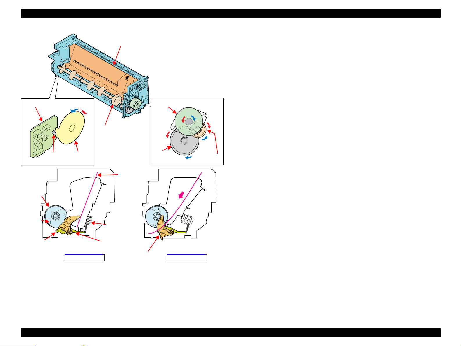
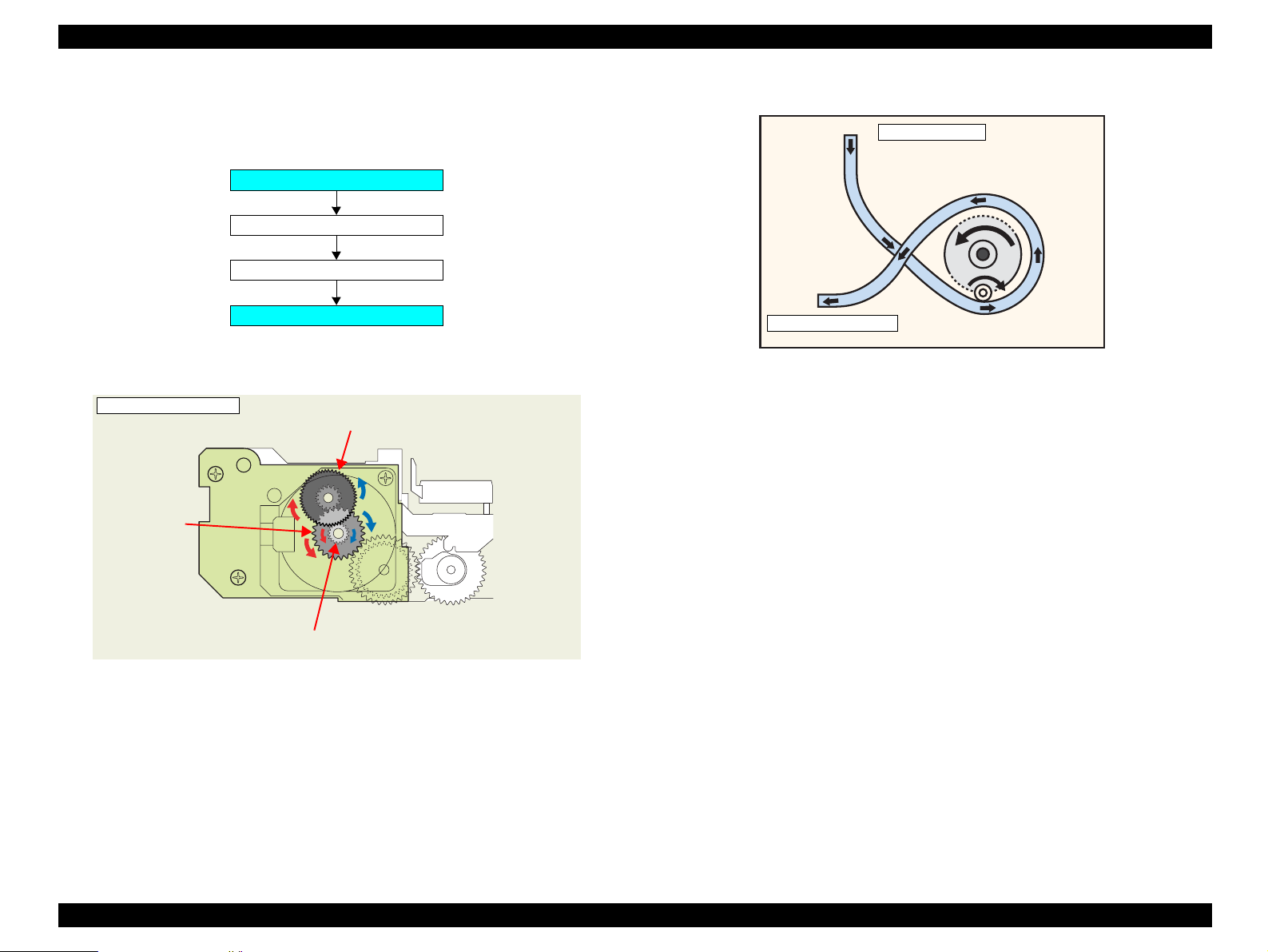
2.2.5.2 Drive Transmission Path to Pump Unit
The drive of the Pump Motor is transmitted to the Pump Unit in the following
path.
Pump Motor
Combination Gear 10.2, 21.2 IS
Spur Gear 20.4 IS
Pump Unit
The following shows the internal part names and operation outline of the Pump
Unit.
<Pump Unit in s ide>
Combination Gear 10.2, 21.2 IS
Spur Gear
20.4 IS
The following shows the Pump Unit operating principle.
Cap Unit Side
To Waste ink pad
Figure 2-10. Pump Unit Operating Principle
Ink Suction
1. The Pinion Gear of the Pump Motor rotates in the CW direction.
2. The Roller turn s and si mult an eou sl y pres se s the tube.
3. Ink is fed from the Cap Unit toward the Waste Ink Pad.
Pu mp Rel ease
1. The Pinion Gear of the Pump Motor rotates in the CCW direction.
2. The Roller moves away from the tube and releases the tube.
Pump Motor and Motor Pini on Ge ar
3. Ink is not sucked.
Figure 2-9. Outline of Pump Unit Inside
Operating Principles Printer Mechanism 27
Page 28
EPSON Stylus Photo R1800/R2400 Revision B
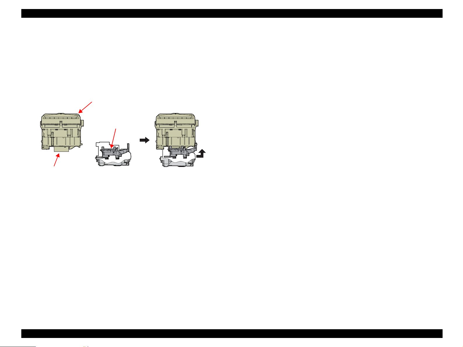
2.2.5.3 Cap Unit
The Cap Unit is designed to make airtight in the Cap sticking fast to the Print
Head surface so that ink suction can be performed by the driving force of the
Pump Unit.
When the printer is in a standby status or its power is OFF, the Cap Unit
prevents the ink from thickening.
The following figures shows the Cap Unit operation.
Carriage Unit
Cap
Print Head
Figure 2-11. Capping M echanism
Slider cap rises to perform
capping.
2.2.6 Ink Sequence
The following ink sequence is executed according to various timer, counter,
flag and other information saved on the EEPROM.
CSIC-related sequence
The ink type code stored in the CSIC Memory Chip is saved in the Main
Board EEPROM. At power-on, data is read from each color CSIC and the
CSIC data status becomes valid. If the data read from each CSIC has any
problem, No Ink Cartridge, CSIC Error or Ink Out will be displayed.
After CSIC operation is checked, the ink consumption of the I/C currently
installed per color is compared with the ink consumption saved in the
printer EEPROM, and control is performed under the following conditions.
When the current ink consumption data differs between the Ink
Cartridge and the EEPROM
1. The printer judges that the Ink Cartridge was replaced while the
printer was turned off. Then it resets the 1st I/C flag in the
EEPROM.
2. The printer updates the number of times the CSIC is installed.
3. After incrementing the counter of I/C replacement, the printer
reads the ink consumption data from the CSIC to write it over the
existing data in the EEPROM following the CSIC data replacement
sequence.
4. The printer model name data on the CSIC is rewritten.
Note:The reason why the model name data is rewritten from the printer
to the CSIC is to know for which model was the I/C used at the
time of collecting used I/Cs.
5. The replacement flag 2 (flag that indicates CL after Replacement)
is set and the CL is executed.
Operating Principles Printer Mechanism 28
Page 29

EPSON Stylus Photo R1800/R2400 Revision B
When the current ink consumption data in the Ink Cartridge and that in
the EEPROM is same
1. When the initial filling flag is set and the CSIC ink consumption is 0,
the printer judges that initial filling is not yet performed.
(The printer before initial filling judges that the I/C is fitted in a
power-off status.)
2. Installation count updating, CSIC information rewriting, and initial
filling are executed in that order.
3. If the initial filling flag is not set, the printer judges that I/C(s) has
not been replaced during power-off and regards the current CSIC
data as valid.
Data is written to the CSIC at the following timings.
At powe r-of f
When starting the power saving mode
When replaced an Ink Cartridge(s)
At the tim e of clean in g
1. Reads the data from the CSIC.
2. Compare the date with the ink consumption data in the EEPROM.
3. If the EEPROM data is same as the CSIC data, ends the
sequence. If they differ, the difference is added to write the sum in
the CSIC.
Initial Ink Filling
When the printer is powered on for the first time after purchase, the printer
executes the initial ink filling operation to fill the ink cavities of the Head
with ink. When the initial ink filling operation is performed properly, the
printer clears the flag in the EEPROM so that initial ink filling operation will
not be performed when it is powered on the next time. The Stylus Photo
R1800 requires about 160 seconds to perform the initial ink filling
operation.
If the sequence does not end normally during initial filling, the initial filling
flag is not cleared and the CL operating flag is set. Because of these flags,
when powered on the next time, the printer assumes that it was powered
off for some reason during initial filling and executes CL3 instead of the
initial filling sequence. (On the conventional mode, initial filling was
executed again. However, when this operation was performed, ink was
wasted and therefore CL3 is executed to cover the ink filling performance.)
When the initial filling flag is set and the CL operating flag is not set, the
printer judges that the initial filling was not executed at all (power was
switched on but the cartridges were not installed), and when the printer is
powered on the next time, it executes initial filling.
Replacement Cleaning
Replacement CL1 is executed when replaced an Ink Cartridge(s).
Amount of Ink Suction
Replacement CL1: 3.09g (0.386g per color)
Operating Principles Printer Mechanism 29
Page 30

EPSON Stylus Photo R1800/R2400 Revision B
Manual Cleaning
This printer provides three different manual cleanings to remove ink
coagulated by air bubbles, viscous material or foreign matter. Perform the
following manual CL operations by operating the panel or using the utility
included in the printer driver.
Independently of the printing path after the previous CL, perform manual
CL from CL1 to CL3 in order if the cumulative printing timer counter is less
than 7min. Only when the cumulative printing timer counter is more than
7min, execute only CL1.
Amount of Ink Suction
• CL1: 1.55g (0.194g per color)
• CL2: 4.08g (0.510g per color)
• CL3: 6.47g (0.809g per color)
Wiping Operation
Clean the nozzle surface with the right-half rubber part of the wiper.
Flushing Operation
Prevent color mixture. Stabilize the ink surface inside the nozzles.
In addition, the printer determines which CL to perform according to the
remaining amount of ink in the Cartridge. When the printer detects the
amount is low, it automatically choose the CL that uses ink less than the
other CLs. If the remaining amount of ink is extremely low (Ink Low or Ink
Out status), the printer disables the all manual Cleanings and indicates the
status on the EPW3.
Timer Cleaning
Ink is consumed depending on the combination of the cumulative printing
timer, cumulative cleaning count and cleaning timer.
Flushing
There are two types of flushing.
Flushing before printing
This is performed to reduce the viscosity of ink in the Print Head
nozzles before starting to print.
Scheduled Flushing
This is performed to prevent ink in the Print Head nozzles from
increasing its viscosity during printing.
2.2.7 Power-On Sequence
The following describes the printer operation after it is powered on.
When the Carriage Unit is in the Home Position wit h the CR Locked
1. After power-on, the drive of the APG Motor is transmitted to the Carriage
Shaft, and the PG position changes from PG Typ. to PG++.
2. The drive of the CR Motor is transmitted to the Carriage Unit, and the
Carriage Unit performs HP detection operation in the following path.
Home position ⇒ Right frame ⇒ CR Lock confirmation position
⇒ Right frame ⇒ Home position
3. The drive of the Pump Motor is transmitted to the Cap Unit, the Cap opens
(lowers), and the CR Lock is released.
4. After the Carriage Unit has moved leftward by the specified number of
steps, the Wiper, driven by the Pump Motor, performs the following.
W ipe r set tin g ⇒ Wiper resetting
5. The Carriage Unit returns to the home position, and the PG position
returns from PG++ to PG Typ.
6. The drive of the PF Motor is transmitted to the PF Roller and Paper Eject
Rollers (front and rear), which then rotate for about 2 seconds.
7. After moving between the left and right frames twice, the Carriage Unit
moves to the right end of the Front Paper Guide.
8. The PF Roller and Paper Eject Rollers (front and rear) rotate.
Rotation for about 4 seconds (slow speed) ⇒ Rotation for about 2
seconds
9. The Carriage Unit returns to the home position and is secured by the CR
Lock.
Operating Principles Printer Mechanism 30
Page 31

EPSON Stylus Photo R1800/R2400 Revision B
When the Carriage Unit is Out of the Home Position
1. When the PG position is other than PG++ after power-on, the drive of the
APG Motor is transmitted to the Carriage Shaft, and the PG position
changes to PG++.
2. The drive of the CR Motor is transmitted to the Carriage Unit, and the
Carriage Unit returns to the home position at slow speed.
3. The drive of the PF Motor is transmitted to the PF Roller and Paper Eject
Rollers (front and rear), which then rotate for about 2 seconds.
4. After the Carriage Unit has moved leftward by the specified number of
steps, the Wiper is set, driven by the Pump.
5. After the Carriage Unit has returned to the home position, it moves leftward
again by the specified number of steps. And, driven by the Pump Motor, ink
is sucked for about 4 seconds and then the Wiper is set, and the CR Lock
is placed.
6. The Carriage Unit performs HP detection operation in the following path.
Home position ⇒ Right frame ⇒ CR Lock confirmation position
⇒ Right frame ⇒ Home position
7. The drive of the Pump Motor is transmitted to the Cap Unit, the Cap opens
(lowers), and the CR Lock is released.
8. The Carriage Unit returns to the home position, and the PG position
returns from PG++ to PG Type.
9. The PF Motor drive is transmitted to the PF Roller and the Paper EJ
Rollers (front and rear) to rotate them for about 2 seconds.
10. The Step 7 to 9 of "When the Carriage Unit is in the Home Position with the
CR Locked (p30)" are performed, and the Carriage Unit is locked.
2.3 Electrical Circuit Operating Principles
The electrical circuit of Stylus Photo R1800 consists of the following circuits.
Control circuit board : C589 MAIN
Power supply circuit board : C589 PSB
Control panel board : C589 PNL
Control panel B board : C589 PNL-B
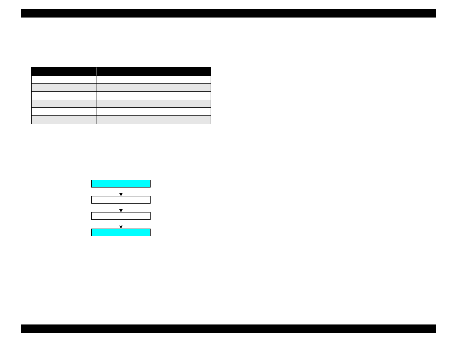
The following shows how the four circuit boards are connected.
PNL Board
MAIN Board
Power OFF +3.3VDC +42VDC
PSB/PSE Power
Supply Board
Printer
Mechanism
CR Motor
PF Motor
APG Motor
ASF Motor
Pump Motor
Head drive circuit
Sensors
Figure 2-12. Electrical Circuit Block Diagram
Operating Principles Electrical Circuit Operating Principles 31
Page 32

EPSON Stylus Photo R1800/R2400 Revision B
2.3.1 Power Supply Circuit Operating Principle
The power supply circuit board of this product is the C589 PSB.
Ba si c ci rc ui t str uc tur e
Flyback switching system
+42VDC and +3.3VDC are supplied to the Printer Mechanism and
Control Board
The following indicates the applications of the voltages generated in this power
supply circuit.
Table 2-9. Supplied Power
Voltage Applications
+42VDC
Rated output current:
0.45A
+3.3VDC
Rated output current:
0.5A
• CR Motor
•PF Motor
•PG Motor
• ASF Motor
• Pump Motor
• Head drive voltage
• Logic sensor circuit
• Sensor circuit
• Nozzle selection circuit (on the Print Head)
• Interfa ce control cir cuit
The following is the block diagram of the power supply circuit.
Separate-excited
Simulated Resonance
Flyback Converter
Over Current Limitation
F51
Fuse for LPS
Over Voltage Limitation
Secondary Power
Supply SW function
Low Power mode
C51, C52
Smoothing
Circuit
D51
IC51
+3.3V Chopper
Circuit
TRANS: T1
+42VDC
+3.3VDC
+5VDC
PSC Signal
ESAVE
QF1
Main Switching
Circuit
AC Input
Over Current
Protection
Filter Circuit
C1, FL1F1, TH1
Full Wave
Rectifier
Circuit
D11, D12,
D13, D14
Smoothing
Circuit
C11
Figure 2-13. Power Supply Circuit Block Diagram
Operating Principles Electrical Circuit Operating Principles 32
Page 33

EPSON Stylus Photo R1800/R2400 Revision B
2.3.2 C589 MAIN Circuit Operating Principle
The C589 MAIN Board consists of the following circuits and sensors.
Logic Circuits (CPU-ASIC 2 in 1, PROM, SDRAM)
Circuits for controlling and driving Motors
(CR Motor, PF Motor, APG Motor, ASF Motor, Pump Motor)
Circuits for controlling and driving the Head
Interface Circuits
USB 2.0, IEEE1394
Sensor Circuits
RTC Circuit
DAC Converter Circuit
Low-power Circuit
Logic Circuit Element for 3.3V/1.5V
The +3.3VDC generated on the C589 PSB Board is transformed to +1.5V
by the Regulator IC on the C589 Main Board to use it to drive multiple
components.
This transformation is performed to reduce power consumption of the Logic
Circuit.
The following components operate with the 3.3V/1.5V.
CR Encoder Sensor
PF Encoder Sensor
PW Sensor
Ink Mark Sensor
APG Sensor
PE Sensor
AS F Se ns or
Com plex Circuit (IC18)
The Complex Circuit (IC18) that consists of EEPROM, RTC, and Reset
circuit is installed on the printer. Employing a large-capacity condenser for
the Timer allows to backup the time recorded at power-off for about a week
after the power-off.
Operating Principles Electrical Circuit Operating Principles 33
Page 34

EPSON Stylus Photo R1800/R2400 Revision B
The following is the block diagram of the C589 MAIN control board.
IEEE 1394
CN3
CR Encoder Sensor
PW Sensor
Ink Mark Sensor
IEEE 1394
(IC1)
PROM
(IC4)
SDRAM
(IC12)
USB2.0
CN2
RTC
(IC18)
CN9
Data
Address
CPU-ASIC
2 in 1
(IC14)
DAC
(IC2)
CN5
Regulator
(IC8)
Motor
Driver
(IC5)
Motor
Driver
(IC6)
Relay Board
CN15
CN16
CN17
CN18
CN19
PF Encoder Sensor
PE Sensor
ASF Sensor
APG Sensor 1
APG Sensor 2
CR Motor
PF Motor
Pump Motor
APG Motor
ASF Motor
CD-R Sensor
C589 PSB Board
C589 Panel Board
CSIC Board
C589 LED Board
CN7
CN10
CN8
Head
Driver
(IC7)
Q13, Q14
CN11
CN12
CN13
CN14
Print Head
Figure 2-14. C589 MAIN Control Board Block Diagram
Operating Principles Electrical Circuit Operating Principles 34
Page 35

TROUBLESHOOTING
CHAPTER
3
Page 36

EPSON Stylus Photo R1800/R2400 Revision B
3.1 Overview
This chapter describes unit-level troubleshooting.
3.1.1 Troubleshooting according to Panel Messages
After checking the printer LED and EPW3 error indications, you can grasp the fault location using the check list in this section. When you find the fault location, refer
to Chapter 4 "Disassembly and Reassembly" and change the corresponding part and/or unit. The following table indicates the check point reference tables
corresponding to the error states (LED and EPW3).
Table 3-1. Reference Tables of Error States
Error State Reference Table
Communication Error Refer to Table 3-2 "Troubleshooting of Communication Error" on page 37
Model Difference Refer to Table 3-2 "Troubleshooting of Communication Error" on page 37
Cover Open (Tray) Error Refer to Table 3-3 "Troubleshooting of Cover Open Error" on page 40
Paper Out Error Refer to Table 3-4 "Troubleshooting of Paper Out Error" on page 40
Paper Jam Error Refer to Table 3-5 "Troubleshooting of Paper Jam Error" on page 44
Card Loading Error Refer to Table 3-6 "Troubleshooting of Card Loading Error" on page 45
Paper Mismatch Error Refer to Table 3-7 "Troubleshooting of Paper Mismatch Error" on page 46
Ink Low Refer to Table 3-8 "Troubleshooting of Ink Low" on page 46
Ink Out Error Refer to Table 3-9 "Troubleshooting of Ink Out Error" on page 46
No Ink Cartridge/CSIC Error Refer to Table 3-10 "Troubleshooting of No Ink Cartridge/Ink Cartridge Error" on page 47
Maintenance Request Error Refer to Table 3-11 "Troubleshooting of Maintenance Request" on page 49
Fatal Error Refer to Table 3-12 "Troubleshooting of Fatal Error" on page 50
Troubleshooting Overview 36
Page 37

EPSON Stylus Photo R1800/R2400 Revision B
Table 3-2. Troubleshooting of Communication Error
Occurrence
Timing
Phenomenon Detail
At power-on The printer does not operate at
all.
Faulty Part/
Part Name
Panel FFC 1. Check that the Panel FFC is connected to the Panel Board
Connector and LED Board Connector.
Panel FFC
Panel Board
connector
Check Point Remedy
1. Connect the Panel FFC to the Panel Board
and LED Board connectors.
Panel FFC
LED Board
Connector
2. Check the Panel FFC for damages. 2. Replace the Panel FFC with a new one.
Panel Board 1. Check the Panel Board for damages. 1. Replace the Panel Board with a new one.
LED FFC 1. Check that the LED FFC is connected to the LED Board
Connector and Main Board Connector CN8.
1. Connect the LED FFC to the LED Board
Connector and Main Board Connector
CN8.
LED FFC
LED Board
Connector
CN8
2. Check the LED FFC for damages. 2. Replace the LED FFC with a new one.
Troubleshooting Overview 37
Page 38

EPSON Stylus Photo R1800/R2400 Revision B
Table 3-2. Troubleshooting of Communication Error
Occurrence
Timing
Phenomenon Detail
At power-on The printer does not operate at
all.
Faulty Part/
Part Name
Power Supply
Board
Check Point Remedy
1. Check that the Connector Cable of the Power Supply
Board is connected to the Main Board Connector CN7.
Connector cable of the
Power Supply Board
CN7
Blue line
1Pin side
2. Check that the blue colored pin of th e Pow er Sup ply Board
Connector cable is inserted into the 1 Pin of the Main
Board Connector CN7 as shown in the above picture.
3. Check that the Fuse F1 on the Power Supply Board has
not blown.
Fuse F1
1. Connect the Connector Cable of the Power
Supply Board to the Main Boar d Connector
CN7.
2. Reconnect the Power Supply Board
Connector cable so that the blue colored
pin is inserted into the 1 Pin.
3. Replace the Power Supply Board with a
new one.
4. Check the components on the Power Supply Board for
damage.
4. Replace the Power Supply Board with a
new one.
Troubleshooting Overview 38
Page 39

EPSON Stylus Photo R1800/R2400 Revision B
Table 3-2. Troubleshooting of Communication Error
Occurrence
Timing
At power-on After the power-on sequence
At operation Operation at power-on is
Phenomenon Detail
has started, the LED turns off
and the printer does not
operate.
normal, but the error appears
when the print job is sent to
the printer.
Faulty Part/
Part Name
Main Board 1. Check that the Relay connector of the ASF Motor and the
Relay connector of the Pump Motor are not connected to
the wrong connector causing a short circuit.
Relay Connector of
the Pump Motor
Interface cable 1. Check that the I nterface cable is conne c ted between the
PC and printer.
2. Check the Interface cable for breaking. 2. Replace the Interface cable with a new
EPSON
USB driver
USB 1. Check that the PC and printer are connected via the USB
1. When using USB, check that the EPSON USB driver has
been installed on the PC.
hub.
Check Point Remedy
Relay Connector of
the ASF Motor
1. Connect the Relay Connector of the ASF
Motor and the Relay C onnector of the
Pump Motor correctly, and replace the
Main Board with a new one.
1. Connect the Interface cable to the PC and
printer.
one.
1. Install the EPSON USB driver.
1. Enter the USB serial No. indicated on the
product nameplate.
Refer to Chapter 5 "Adjustment".
IEEE1394 1. Check that the same code as the IEEE1394 QR la bel code
is saved in the EEPROM address (from BA-H to BE-H).
Printer Driver 1. Check that the printer driver for Stylus Photo R1800 has
already been installed.
2. Check that the connected printer is Stylus Photo R1800. 2. Connect the Stylus Photo R1800 printer.
Main Board 1. Check that a wron g mo del nam e has not been input to the
EEPROM address (E0<H<) on the Main Board.
1. Input the code given as the IEEE1394 QR
label code.
Refer to Chapter 5 "Adjustment".
1. Install the printer driver for Stylus Photo
R1800.
1. Using the Adj ustment Prog ram, enter the
correct model name (save 01 into E0<H>).
Refer to Chapter 5"Adjustment".
Troubleshooting Overview 39
Page 40

EPSON Stylus Photo R1800/R2400 Revision B
Table 3-3. Troubleshooting of Cover Open Error
Occurrence
Timing
Phenomenon Detail
During printing A Cover Open (Tray) Error is
indicated during printin g.
Occurrence
Timing
Phenomenon Detail
At operation When the Paper Switch is
pressed, the LD Roller attempt
to feed paper but the paper is
not fed.
Faulty Part/
Part Name
Check Point Remedy
Printer Cover 1. Check that the CD-R Unit is not open. 1. Close the CD-R Unit.
Table 3-4. Troubleshooting of Paper Out Error
Faulty Part/
Part Name
ASF Assy. 1. Check the LD Roller or Retard Roller of the ASF Assy for
paper dust and foreign matter.
Check Point Remedy
1. Using a cleaning sheet (part
code:1262115), clean the LD Roller and
Retard Roller. The procedure is as follows.
(1) Place the cleaning sheet upside down
and put it into the ASF Assy.
(2) Press the Paper Switch to start paper
feed.
(3) R epeat the above steps several times.
* To remove persistent contamination,
staple an alcohol-dampe ned cloth to a
postcard and clean the rollers in the
following method.
Cleaning sheet Postcard used
Non-adhesive part
as mount
Adhesive part
This side down
Stapling
Cloth damped
with alcohol
(1) Place the alcohol-dampened cloth
toward the LD Roller surface of the
ASF Assy.
(2) Hold the mount top end securely and
press the Paper Switch.
(3) Repeat the paper feed sequence
several times to clean the LD Roller
surface of the ASF Assy.
Troubleshooting Overview 40
Page 41

EPSON Stylus Photo R1800/R2400 Revision B
Table 3-4. Troubleshooting of Paper Out Error
Occurrence
Timing
Phenomenon Detail
At operation Though paper is fed from the
ASF Assy, it stops near the PE
Sensor Lever.
Faulty Part/
Part Name
Check Point Remedy
PE Sensor 1. Check that the Connector cable of the PE Sensor is
securely connected to the PE Sensor and Relay Board
Connector CN2.
PW Sensor Connector
CN2
2. Check that the Sensor Holder is mounted to the
Mechanical frame correctly.
Sensor Holder
Detection Lever
Torsion Spring
1. Connect the Connector cable of the PE
Sensor to the PE Sensor and Rel ay Boa rd
Connector CN2.
2. Install the Sensor Holder correctly.
3. Move the Detection Lever manually as when the paper
passes, and check that the Detection Lever returns to the
3. Replace the PE Sensor Holder Unit with a
new one.
original position automatically by the Torsion Spring when
released. Refer to the above photo.
4. Using a tester, check that the PE Sensor is normal.
⋅ Paper absent : 2.4V or more
4. Replace the PE Sensor Holder Unit with a
new one.
⋅ Paper present : 0.4V or less
Troubleshooting Overview 41
Page 42

EPSON Stylus Photo R1800/R2400 Revision B
Table 3-4. Troubleshooting of Paper Out Error
Occurrence
Timing
The Paper Switch
was pressed at the
setting of the CD-R
Tray.
The Paper Switch
was pressed at the
setting of the CD-R
Tray or board
paper
Phenomenon Detail
The CD-R Tray HP detection
sequence stops and the Tray
is ejected.
Though the CD-R Tray or the
Board Paper is fed toward the
ASF Assy, but is ejected
immediately.
Faulty Part/
Part Name
CD-R Tray 1. Check the HP detection position or white markings of the
CD-R Tray for paper dust and foreign matter.
White Markings
2. Check the Driven Rolle r s urf ace for contaminati on s uc h as
paper dust and CD-R coating material.
Check Point Remedy
1. Remove paper dust and/or foreign matter
from the detection position.
HP detection
position
2. Feed A4-size sheets of plain paper from
the ASF Assy several times to remove the
contamination.
3. Check that the HP detection position or white markings of
3. Replace the CD-R Tray with a new one.
the CD-R Tray are not chipped.
PW sensor 1. Check the PW Sensor for paper dust, ink, etc. 1. Clean the PW Sensor surface.
PW sensor
Carriage Unit Bottom
2. Compare the EEPROM values in two places (50<H> and
2. Replace the PW Sensor with a new one.
51<H>) and check that they are not approximate to each
other.
Troubleshooting Overview 42
Page 43

EPSON Stylus Photo R1800/R2400 Revision B
Table 3-4. Troubleshooting of Paper Out Error
Occurrence
Timing
The Paper Switch
was pressed at the
setting of the CD-R
Tray or board
paper
Phenomenon Detail
The CD-R Tray moves toward
the ASF and the posterior
edge of it reaches to the
Driven Roller on the Upper
Paper Guide.Then the CD-R
Tray tries to go farth er, but i t is
ejected.
Faulty Part/
Part Name
Check Point Remedy
PW sensor 1. Check that the PW Sensor FFC is placed in the specified
routing positions and does not make contact with any
parts.
CR Encoder Board
Connector
FFC
PW Sensor
Connector
2. Check that the PW Sensor FFC is connected to the CR
Encoder Board and PW Sensor Connectors. Refer to the
above photo.
3. Check the PW Sensor or PW Sensor FFC for damages. 3. Replace the PW Sensor with a new one.
1. Place the PW Sensor FFC in the specified
routing p ositions.
2. Connect the FFC to the CR Enco der Board
and PW Sensor Connectors.
Troubleshooting Overview 43
Page 44

EPSON Stylus Photo R1800/R2400 Revision B
Table 3-5. Troubleshooting of Paper Jam Error
Occurrence
Timing
At operation At the time of paper ejection,
Phenomenon Detail
the PF Roller advances the
paper but cannot eject it
completely.
Paper is not ejected
completely and causes a jam
near the Paper Eject Frame.
Faulty Part/
Part Name
– 1. Check that the size of the fed paper is not larger than that
of the paper specified by the driver.
ASF Assy. 1. Check that the paper is fed along the Right Edge Guide. 1. Feed the paper along the Right Edge
Paper EJ Frame
Assy.
Spur Gear 68
Spur Gear 16; B
Paper EJ Roller
Assy.(front/rear)
1. Check that the Star Wheel Units have not come off the
Paper EJ Frame Assy.
Paper EJ Frame Assy.
2. Check the Paper EJ Frame Assy for deformation or
damages.
1. Check the Spur Gear 68 or Spur Gear 16; B for damages. 1. Replace the Front (or Rear) Paper EJ
Spur Gear 16; B
Check Point Remedy
1. Tell the user that the paper size specified
by the driver is not available for the printer.
Guide.
1. Securely install the Star Wheel Units to the
Paper EJ Frame Assy.
Star Wheel Units
2. Replace the Paper EJ Frame Assy with a
new one.
Roller Assy with a new one.
Spur Gear 68
Troubleshooting Overview 44
Page 45

EPSON Stylus Photo R1800/R2400 Revision B
Table 3-6. Troubleshooting of Card Loading Error
Occurrence
Timing
Phenomenon Detail
During printing Printing starts but paper is not
fed.
The card size paper is loaded
correctly, but Card Loading
Error is displayed.
Faulty Part/
Part Name
– 1. Check that the card size paper is loaded in the portrait
PW sensor
Check Point Remedy
1. Load the cards of the same size correctly,
orientation.
and press t he Paper Switch to eject the
jammed paper.
1. Check that the PW Sensor FFC is connected to the CR
Encoder Board and PW Sensor Connectors.
CR Encoder Board
Connector
FFC
PW Sensor
Connector
1. Connect the FFC to the CR Enco der Board
or PW Sensor.
2. Check the PW Sensor or PW Sensor FFC for damages. 2. Replace the PW Sensor with a new one.
Troubleshooting Overview 45
Page 46

EPSON Stylus Photo R1800/R2400 Revision B
Table 3-7. Troubleshooting of Paper Mismatch Error
Occurrence
Timing
At operation When feeding a CD-R (Board
Occurrence
Timing
At operation or
during printing
Phenomenon Detail
Paper), an error is displayed
on the LED and EPW3.
Phenomenon Detail
A message is displayed on
the LED and EPW3 during
printing.
Faulty Part/Part
Name
Paper EJ Frame
Assy
(CD-R Tray Base)
CD-R Sensor 1. Check that the Connector cable of the CD-R Sensor is
1. Check if the CD-R Tray Base is closed or not. 1. Open the CD-R Tray Base.
securely connected to the connectors of the CD-R Sensor
and Panel Board.
CD-R Sensor
Connector cable of
the CD-R Sensor
2. Check the CD-R Sensor or Connector cable for damages. 2. Replace the CD-R Sensor with a new one.
Check Point Remedy
Panel Boa r d c o nnector
Table 3-8. Troubleshooting of Ink Low
Faulty Part/Part
Name
Ink Cartridge 1. Look at the remaining ink indication of the EPW3 to check
the amount of the ink remaining in the Ink Cartridge.
Check Point Remedy
1. Connect the Connector cable of the CD-R
Sensor to the CD-R Sensor and Panel
Board Connectors.
1. Prepare a new Ink Cartri dge.
Table 3-9. Troubleshooting of Ink Out Error
Occurrence
Timing
During printing After the Carriage has
Phenomenon Detail
detected the HP, an error is
displayed on the LED and
EPW3.
Faulty Part/Part
Name
Ink Cartridge 1. Look at the remaining ink indication of the EPW3 to check
whether the ink remains in the Ink Cartridge.
Check Point Remedy
1. Replace the Ink Cartridge with a new one.
Troubleshooting Overview 46
Page 47

EPSON Stylus Photo R1800/R2400 Revision B
Table 3-10. Troubleshooting of No Ink Cartridge/Ink Cartridge Error
Occurrence
Timing
At power-on After the Carriage has
Phenomenon Detail
detected the HP, an error is
displayed on the LED and
EPW3.
Faulty Part/
Part Name
Ink Cartridge 1. Check that the Ink Cartridge is installed correctly. 1. Install the Ink Cartridge correctly.
2. Check that the tab of the Ink Cartridge is not broken. 2. Replace the Ink Cartridge with a new one.
3. Check that the Memory Chip is not disconnected or not
damaged.
Check Point Remedy
Tab
3. Replace the Ink Cartridge with a new one.
Memory Chip
Troubleshooting Overview 47
Page 48

EPSON Stylus Photo R1800/R2400 Revision B
Table 3-10. Troubleshooting of No Ink Cartridge/Ink Cartridge Error
Occurrence
Timing
Phenomenon Detail
At power-on After the Carriage has
detected the HP, an error is
displayed on the LED and
EPW3.
Faulty Part/
Part Name
CSIC FFC 1. Check that the CSIC FFC is connected to the CSIC Board
Connector and Main Board Connector CN10.
Check Point Remedy
1. Connect the CSIC FFC to the CSIC Board
Connector and Main Board Connector
CN10.
CSIC Board
Connector
CSIC FFC
CN10
2. Check the CSIC FFC for damage. 2. Replace the CSIC FFC with a new one.
CSIC Board 1. Check the CSIC Board for damage. 1. Replace the CSIC Board with a new one.
CSIC Board
Carriage Unit 1. Check that the electrodes in the Carriage, which make
1. Replace the Carriage Unit with a new one.
contact with the CSIC Board, are not bent.
Electrode
Troubleshooting Overview 48
Page 49

EPSON Stylus Photo R1800/R2400 Revision B
Table 3-11. Troubleshooting of Maintenance Request
Occurrence
Timing
At power-on At power-on, the printer does
Phenomenon Detail
not operate at all.
Faulty Part/
Part Name
Waste Ink Pads 1. Using the Adjustment Program, check if the Protection
Counter A+B value has exceeded 17772.
Check Point Remedy
1. Replace the Waste Ink Pads an d re set the
Protection Counter A and B value with the
Adjustment Program.
• Home side: 24<H>, 25<H>
• Opposite-to-home side: 26<H>, 27<H>
Troubleshooting Overview 49
Page 50

EPSON Stylus Photo R1800/R2400 Revision B
Table 3-12. Troubleshooting of Fatal Error
Occurrence
Timing
At power-on At power-on, the CR Motor
Phenomenon Detail
does not operate at all.
Faulty Part/
Part Name
CR Motor 1. Check that the CR Motor connector cable is connected to
the Relay Connector.
CR Motor
Relay Connector
2. Check the CR Motor connector cable for damages. 2. Replace the CR Motor with a new one.
3. Check if the CR Motor operates normally. 3. Replace the CR Motor with a new one.
Relay
Connector
Cables
(for the CR
Motor)
1. Check that the Relay Connec tor Ca ble is c onn ec ted to the
Main Board Connector CN15.
Check Point Remedy
1. Connect the CR Motor connector to the
Relay Connector.
1. Connect the Relay Connector Cabl e to t he
Main Board Connector CN15.
CN15
2. Check the Relay Connector Cable for damages. 2. Replace the Relay Connector Cable with a
new one.
Troubleshooting Overview 50
Page 51

EPSON Stylus Photo R1800/R2400 Revision B
Table 3-12. Troubleshooting of Fatal Error
Occurrence
Timing
At power-on The power-on sequence is
Phenomenon Detail
executed but Fatal error is
displayed.
At power-on, the PF Motor
does not operate at all.
Faulty Part/
Part Name
CR drive
mechanism
PF Motor 1. Check that the Connector Cable of the PF Motor is
1. Check that the Carriage Shaft is lubricated with grease. 1. Wipe the surface of the Carriage Shaft with
Carriage Shaft
connected to the Main Board Connector CN16.
Check Point Remedy
a dry, soft cloth, and lubricate the Carriage
Shaft with grease G-71.
Refer to Chapter 6 "Maintenance".
1. Connect the PF Motor connector cable to
the Main Board Connector CN16.
CN16 PF Motor
2. Check the PF Motor connector cable for damages. 2. Replace the PF Motor with a new one.
3. Check if the PF Motor operates normally. 3. Replace the PF Motor with a new one.
Troubleshooting Overview 51
Page 52

EPSON Stylus Photo R1800/R2400 Revision B
Table 3-12. Troubleshooting of Fatal Error
Occurrence
Timing
At power-on At power-on, the APG Motor
Phenomenon Detail
does not operate at all.
At power-on, the Pump Motor
does not operate at all.
Faulty Part/
Part Name
APG Motor 1. Check that the Connector Cable of the APG Motor is
connected to the Main Board Connector CN18.
2. Check the APG Motor connector cable for damage. 2. Replace the APG Motor with a new one.
3. Check if the APG Motor operates normally. 3. Replace the APG Motor with a new one.
Pump Motor 1. Check that the Pump Motor connector cable is connected
to the Relay Connector.
Check Point Remedy
APG Motor
CN18
1. Connect the APG Motor connector cable to
the Main Board Connector CN18.
1. Connect the Pump Motor connector cable
to the Relay Connector.
Relay Connector
2. Using a tester, check the resistance value of the Pump
Motor.
Value of resistance : 10.3Ω ± 10%
3. Check the Pump Motor connector cable for damages. 3. Replace the Ink System Unit with a new
2. If the resistance value is abnormal, replace
the Ink System Unit with a new one.
one.
Troubleshooting Overview 52
Page 53

EPSON Stylus Photo R1800/R2400 Revision B
Table 3-12. Troubleshooting of Fatal Error
Occurrence
Timing
At power-on At power-on, the Pump Motor
Phenomenon Detail
does not operate at all.
While the power-on sequence
is being executed, Fatal error
is displayed.
Faulty Part/
Part Name
Relay
Connector
Cables (for
Pump Motor)
APG Sensor 1. Check that the APG Sensor Connector cables are
1. Check that the Relay Connec tor Ca ble is c onn ec ted to the
Main Board Connector CN17.
2. Check the Relay Connector Cable for damages. 2. Replace the Relay Connector Cable with a
connected to the APG Sensors and Relay Board
Connector CN4 and CN5.
Check Point Remedy
CN17
APG Sensors
1. Connect the Relay Connector Cabl e to t he
Main Board Connector CN17.
new one.
1. Connect the APG Sensor Connector
cables to the APG Sensors and Relay
Board Connector CN4 and CN5.
CN4
CN5
2. Check the APG Sensors for damages. 2. Replace the APG Sensors with new ones.
Troubleshooting Overview 53
Page 54

EPSON Stylus Photo R1800/R2400 Revision B
Table 3-12. Troubleshooting of Fatal Error
Occurrence
Timing
At power-on While the power-on sequence
Phenomenon Detail
is being executed, Fatal error
is displayed.
Faulty Part/
Part Name
ASF Motor 1. Check that the Connector cable of the ASF Motor is
connected to the Relay Connector.
2. Using a tester, check the resistance value of the ASF
Motor.
Value of resistance : 7.0Ω ± 10%
3. Check the ASF Motor connector cable for damages. 3. Replace the ASF Motor with a new one.
Relay
Connector
Cable
(for the ASF
Motor)
1. Check that the Relay Connec tor Ca ble is c onn ec ted to the
Main Board Connector CN19.
Check Point Remedy
ASF Motor
Relay Connector
1. Connect the Connector cable of the ASF
Motor to the Relay Connector.
2. If the resistance value is abnormal, replace
the ASF Motor with a new one.
1. Connect the Relay Connector Cabl e to t he
Main Board Connector CN19.
CN19
2. Check the Relay Connector Cable for damages. 2. Replace the Relay Connector Cable with a
new one.
Troubleshooting Overview 54
Page 55

EPSON Stylus Photo R1800/R2400 Revision B
Table 3-12. Troubleshooting of Fatal Error
Occurrence
Timing
Phenomenon Detail
At power-on While the power-on sequence
is being executed, Fatal error
is displayed.
At power-on, the Carria ge U nit
moves away from the home
position and bumps against
the right of the Frame, then
hits the left of the Frame.
Faulty Part/
Part Name
Check Point Remedy
Relay FFC 1. Check that the Relay FFC is connected to the Rela y Board
Connector CN1 and Main Board Connector CN5.
CN1
CN5
2. Check the Relay FFC for damages. 2. Replace the Relay FFC Cable with a new
CR Scale 1 . Check that the CR Scale is inserted in the slit of the CR
Encoder Sensor.
CR Scale
1. Connect the Relay FFC to the Relay Board
Connector CN1 and Main Board
Connector CN5.
one.
1. Insert the CR Scale into the slit of the CR
Encoder Sensor.
CR Encoder
Sensor Board
2. Check the CR Scale for damages and dirt. 2. Wipe off the dirt completely or replace the
CR Scale with a new one.
CR Encoder
Sensor Board
1. Check the CR Encoder Sensor for paper dust, etc. 1. Remove the paper dust, etc. from the CR
Encoder Sensor.
2. Check the CR Encoder Sensor Board for damages. 2. Replace the CR Encoder Sensor Board
with a new one.
Troubleshooting Overview 55
Page 56

EPSON Stylus Photo R1800/R2400 Revision B
Table 3-12. Troubleshooting of Fatal Error
Occurrence
Timing
Phenomenon Detail
At power-on At power-on, the Carria ge U nit
moves away from the home
position and bumps against
the right of the Frame, then
hits the left of the Frame.
At power-on, the PF Roller
rotates fast about a half turn.
Faulty Part/
Part Name
Check Point Remedy
Sensor FFC 1. Check that the Sensor FFC is connected to the CR
Encoder Sensor Board Connector and Main Board
Connector CN9.
CR Encoder Sensor
Board Connector
CN9
2. Check the Sensor FFC for damages. 2. Replace the Sensor FFC with a new one.
PF Encoder
Sensor Holder
1. Check that the PF Encoder Sensor Holder is mounted
correctly.
2. Check that the FFC of the PF Encoder Sensor is securely
connected to the PF Encoder Sensor Board Connector
and Relay Board Connector CN6.
CN6
1. Connect the Sensor FFC to the CR
Encoder Sensor Board Connector and
Main Board Connector CN9.
1. Install the PF Encoder Sensor Holder
correctly.
2. Connect the PF Encoder Sensor FFC to
the PF Encoder Sensor Board and Relay
Board Connector CN6.
PF Encoder Sensor
Board Connector
3. Check the PF Encoder Sensor for paper dust, etc. 3. Remove the paper dust, etc. from the PF
Encoder Sensor.
4. Check if the PF Encoder or the FFC is damaged. 4. Replace the PF Encoder with a new one.
Troubleshooting Overview 56
Page 57

EPSON Stylus Photo R1800/R2400 Revision B
Table 3-12. Troubleshooting of Fatal Error
Occurrence
Timing
At power-on At power-on, the PF Roller
During printing After receiving a print data, or
Phenomenon Detail
rotates fast about a half turn.
while performing the CD-R
Tray home position detection
sequence (Board Paper
detection), an error is
displayed on the LED and
EPW3.
Faulty Part/
Part Name
PF Scale 1. Check that the PF Scale is inserted in the slit of the PF
Encoder Sensor.
2. Check the PF Scale for damages and dirt. 2. Replace the PF Scale with a new one.
Head FFC
Sensor FFC
1. Check that the Head FFC and the Sensor FFC are
securely connected to the Main Board Connectors CN9
through CN14.
Check Point Remedy
PF Scale
Slit
1. Install the PF Scale in the slit of the PF
Encoder Sensor correctly.
1. Connect the Head FFC and the Sensor
FFC to the Main Board Connectors CN9
through CN14.
CN9 through CN14
Troubleshooting Overview 57
Page 58

EPSON Stylus Photo R1800/R2400 Revision B
Table 3-12. Troubleshooting of Fatal Error
Occurrence
Timing
During printing After starting to print, ink is not
Phenomenon Detail
ejected and paper stops
midway.
Ink is not ejected from most
nozzles.
Faulty Part/
Part Name
Head FFC 1. Check that the Head FFC is securely connected to the
Print Head Connector a nd Main Board Connectors CN10,
CN12, CN13, and CN14.
2. Check the Head FFC for damages. 2. Replace the Head FFC with a new one.
Print Head 1. Check for occurrence of Head Hot. 1. Replace the Print Head with a new one.
Check Point Remedy
1. Connect the Head FFC to the Print Head
Connector and Main Board Connectors
CN10, CN12, CN13, and CN14.
Head FFC
Print Head
Connector
Troubleshooting Overview 58
Page 59

EPSON Stylus Photo R1800/R2400 Revision B
3.1.2 Troubleshooting based on Observed Faults
This section provides troubleshooting procedures based on observed faults such as print quality troubles and abnormal noise.
Table 3-13. Print Quality Troubles
Observed Faults Details of the Fault
Dot missing and
mixed colors
Inks are not ejected from the
Print Head to the Cap.
Faulty Part/
Part Name
Ink System
Unit(Cap)
Check Point Remedy
1. Check for foreign matter around the Seal Rubber on the
Cap Unit.
Seal Rubbers
Extension Spring, 1.19 IS
2. Check that the Ink Tube is connected to the Pump Tube. 2. Connect the Ink Tube to the Pump Tube
Ink Tubes Pump Tube
1. Remove the foreign matter aroun d the Seal
Rubber completely.
securely.
Connectio n point
3. Check that the Extension Spring 1.19 IS is correctly
installed to the Cap Unit.
3. Replace the Ink System Unit with a new
one.
Troubleshooting Overview 59
Page 60

EPSON Stylus Photo R1800/R2400 Revision B
Table 3-13. Print Quality Troubles
Observed Faults Details of the Fault
Dot missing and
mixed colors
Although inks are ejected
from the Print Head to the
Cap, the trouble still occurs
after executing a cleaning
cycle or replacing the Ink
Cartridges.
Faulty Part/
Part Name
Print Head 1. Run a Nozz le Check , and chec k the prin ted patt ern if it has
broken lines or missing segments.
2. Check that the Head FFC is securely connected to the
Print Head Connector and Main Board Connectors CN11,
CN12, CN13, and CN14.
3. Check if the Head FFC is not damaged. 3. Replace the Head FFC with a new o ne.
Check Point Remedy
Head FFC
Print Head
Connector
1. After running a Head Cleaning, check the
Nozzle Check Pattern again.
2. Connect the Head FFC to the Print Head
Connector and Main Board Connectors
CN11, CN12, CN13, and CN14.
If the trouble still occurs after replacing it,
replace the Print Head with a new one.
Ink System Unit
Cleaner Blade
Main Board 1. Check the Main Board for damages. 1. Replace the Mai n Board with a new one.
1. Check if the Cleaner Bla de is covered wit h pape r dust or is
bent.
Cleaner Blade
1. Replace the Ink System Unit with a new
one.
Troubleshooting Overview 60
Page 61

EPSON Stylus Photo R1800/R2400 Revision B
Table 3-13. Print Quality Troubles
Observed Faults Details of the Fault
Horizontal or
vertical banding /
Getting smeared
Although inks are ejected
from the Print Head to the
Cap, almost nothing is printed
or the print gets sme ared with
excessive ink after executing
a cleaning cycle or replacing
the Ink Cartridges.
Faulty Part/
Part Name
Head FFC 1. Check that the Head FFC is securely connected to the
Print Head Connector and Main Board Connectors CN10,
CN12, CN13, and CN14.
Print Head 1. Check if the print quality recovers after running a cleaning
or replacing the Ink Cartridges.
Main Board 2. Check the Main Board for damages. 2. Replace the Mai n Board with a new one.
Check Point Remedy
1. Connect the Head FFC to the Print Head
Connector and Main Board Connectors
CN10, CN12, CN13, and CN14.
Head FFC
Print Head
Connector
1. Run the cleaning and replace the Ink
Cartridges several times. If the trouble still
occurs, replace the Print Head wi th a new
one.
Troubleshooting Overview 61
Page 62

EPSON Stylus Photo R1800/R2400 Revision B
Table 3-13. Print Quality Troubles
Observed Faults Details of the Fault
Vertical or
horizontal banding /
Color shading
The printout has banding
vertical to the CR moving
direction and is not evenly
colored.
Direction of
CR movement
* If the trouble still occurs
after doing all measures
described in the right-hand
columns, replace the CR
Motor with a new one.
Narrow stripes of the same
width appear horizontally to
the CR moving direction.
Direction of
CR movement
Faulty Part/
Part Name
Adjustment 1. For printing in the Bi-D mode, check that the Bi-D
Adjustment has been performed properly.
Print Head 1. Run a Nozzle Check, and check t he printed pattern i f it has
broken lines or missing segments.
Carriage Shaft 1. Check the surfaces of the Carriage Shaft for foreign
matter.
2. Check that the Carriage Shaft is fully lubricated with
grease.
3. Check that the Carriage Shaft is mounted horizontally. 3. Reassemble the Carriage Shaft correctly.
4. Check the Carriage Shaft for damages. 4. Replace the Carriage Shaft with a new one.
Printer Driver
and the Paper
Print Head 1. Run a Nozzle Check, and check t he printed pattern i f it has
1. Check if appropriate paper is used in accordance with the
Printer Driver settings.
broken lines or missing segments.
Check Point Remedy
1. Perform Bi-D Adjustment to eliminate
displacements between the upper and
lower lines.
Refer to Chapter 5 "Adjustment".
1. Perform the Head Cleaning, then check the
Nozzle Check Pattern.
Refer to Chapter 5
If the trouble still occurs, replace the Print
Head with a new one.
1. Remove foreign matter from the Carriage
Shaft.
2. Wipe the grease applied to the Carriage
Shaft with a dry, soft cloth, and then apply
G-71 grease.
Refer to Chapter 6 "Maintenance".
1. Use the appropriate type of paper in
accordance with the Printer Driver.
1. Perform the Head Cleaning, then check the
Nozzle Check Pattern.
Refer to Chapter 5
If the trouble still occurs, replace the Print
Head with a new one.
"Adjustment"
"Adjustment"
.
.
PF Roller Shaft 1. Check the surface of the PF Roller Shaft for foreign matter. 1. Clean the PF Roller surface carefully.
2. Check the PF Roller Shaft for damages. 2. Replace the PF Roller with a new one.
* If the trouble still occurs
after doing all measures
described in the right-hand
columns, replace the PF
Motor with a new one.
Troubleshooting Overview 62
Page 63

EPSON Stylus Photo R1800/R2400 Revision B
Table 3-13. Print Quality Troubles
Observed Faults Details of the Fault
Vertical or
horizontal banding /
Color shading
When printing at 360 dpi,
horizontal banding and color
unevenness appears at a
constant frequency.
Star Wheel Rollers traces
appear in the CR moving
direction.
Printout is faint or blurry. Printer Driver
Faulty Part/
Part Name
Adjustment 1. Check that PF Adjustment has executed properly. 1. Perform PF Adjustment properly.
2. Check for Dot missing. 2. Replace the Ink System Unit with a new
Paper EJ Frame
Assy.
and the Paper
Print Head 1. Using the Adjustment Program, check that the correct Head
1. Check that the Star Wheel Units have not come off or the
Star Wheel Rollers turns normally.
Star Wheel Rollers
1. Check that adequate paper is used accord ing to the se tting
of the Printer Driver.
ID has been written to the EEPROM.
Check Point Remedy
Refer to Chapter 5 "Adjustment".
one.
1. Install the Star Wheel U nits to t he Paper EJ
Frame Assy correctly.
Star Wheel Units
1. Use the appropriate type of paper in
accordance with the Printer Driver.
1. Using the Adjustment Program, enter the
31- digit code of the Head ID to the
EEPROM.
Refer to Chapter 5 "Adjustment".
Paper EJ Roller
traces appear on
the printout.
The bottom of the printout is
not evenly colored.
Traces of the Paper EJ Roller
appear on the printed paper
or CD-R.
Adjustment 1. Check if the Positioning Adjustment of PF Roller Shaft
Retainer has been performed properly .
Printer Driver
and the Paper
Front and Rear
Paper EJ Roller
Assys.
1. Check if appropriate paper is used in accordance with the
Printer Driver settings.
1. Check if the Paper EJ Roller is clean or not. 1. Clean the Pape r EJ Roller using the Roller
1. Make adjustments according to the
specified adjustment priority.
Refer to Chapter 5 "Adjustment".
1. Use the appropriate type of paper in
accordance with the Printer Driver.
Cleaning Mode.
Troubleshooting Overview 63
Page 64

EPSON Stylus Photo R1800/R2400 Revision B
Table 3-13. Print Quality Troubles
Observed Faults Details of the Fault
The printout is
stained with ink.
The non-printed side or the
bottom of the printout is dirty
with ink.
When the paper size in the
sent print data is lar ger than
the size of the fed paper, data
are printed on the Front
Paper Guide, extending off
the paper.
Ink smudges appear on the
blank area of the printout.
Faulty Part/
Part Name
Front Paper
Guide Pad
PW sensor 1. Check that the PW Sensor FFC is connected. 1. Connect the PW Sensor FFC.
Paper EJ Frame
Assy.
1. Check that heaps of ink are not formed on the Front Paper
Guide Pad and tha t the Front Paper Gui de Pad is i ns tal led
securely and evenly in the setting position.
Front Paper Guide Pad Front Paper Guide
2. Check that the PW Sensor is not faulty. 2. Replace the PW Sensor with a new one.
1. Check the Star Wheel Rollers for ink stain. 1. Clean the Star Wheel Rollers with a soft
Check Point Remedy
1. If heaps of ink are formed, replace the
Front Paper Guide . If it has been co nfirmed
that the Ink pads have risen, reinstall the
Front Paper Guide Pad correctly.
cloth.
Front Paper
Guide
Front Paper
Guide Pad
1. Check the Front Paper Guide for ink stain. 1. Clean the Front Paper Guide with a soft
cloth.
1. Check if ink heaps are formed on the Front Paper Guide
Pad.
1. Replace the Front Paper Guide with a new
one.
Troubleshooting Overview 64
Page 65

EPSON Stylus Photo R1800/R2400 Revision B
Table 3-13. Print Quality Troubles
Observed Faults Details of the Fault
The printout is
stained with ink.
Ink smudges appear on the
blank area of the printout.
Faulty Part/
Part Name
Front and Rear
Paper EJ Roller
Assys
Driven Roller
Shaft
Ink System Unit 1. Check that wiping operation was performed properly. 1. Install the Cleaner blade correctly or
1. Check the Front and Rear Paper EJ Roller Assys for ink
stain.
1. Check the Driven Roller Shaft for ink stain. 1. Clean the Driven Roller Shaft with a soft
Check Point Remedy
1. Clean the Front and Rear Paper EJ Roller
Assys with a soft cloth.
Driven Roller Shaft
Rear Paper EJ Roller AssyFront Paper EJ Roller Assy
cloth.
replace it with a new one.
Cleaner Blade
Troubleshooting Overview 65
Page 66

EPSON Stylus Photo R1800/R2400 Revision B
Table 3-13. Print Quality Troubles
Observed Faults Details of the Fault
The printout is
stained with ink.
The printout is
grainy.
Ink smudges appear on the
blank area of the printout.
Images are printed grainy in
all print modes. Or the image
looks rough.
When printed at 5760 dpi, the
printed images are poor or
grainy.
Faulty Part/
Part Name
PF Roller Shaft 1. Check the PF Roller Shaft for ink stain. 1. Clean the PF Roller Shaft with a soft cloth.
PF Roller Shaft
Adjustment
Main Board
Print Head
Adjustment
Main Board
Print Head
1. Check that PG, Bi-D and Head Angular Adjustments have
been made properly.
2. Print the adjustment check patterns and check if they are
grainy.
1. After making sure that PG, Bi-D and Head Angular
Adjustments have been made correctly, check whether
PW Sensor has been adjusted properly.
2. Print the adjustment check patterns and check if the
printed ima ges are still poor or gra iny.
Check Point Remedy
1. Make the adjustments according to the
specified adjustment priority.
Refer to Chapter 5 "Adjustment".
2. If the images look still grainy after
adjustment, replace the Main Board with a
new one.
1. Make the adjustment according to the
specified adjustment priority.
Refer to Chapter 5 "Adjustment".
2. If the image quality does not improve after
the adjustment, repla ce the Pri nt Head a nd
Main Board in this order, and check the
image graininess.
Regarding hue of
images
The whole image is reddish. Adjustment
Print Head
1. Check if the PG has been adjusted properly. 1. Make the adjustment according to the
specified adjustment priority.
Refer to Chapter 5 "Adjustment".
2. Check that Bi-D and Head Angula r Adjustments ha ve been
made properl y.
3. Print the adjustment check patterns and check the image
color.
2. Make the adjustments according to the
specified adjustment priority.
Refer to Chapter 5 "Adjustment".
3. If the image color does not change after
adjustment, replace the Print Head with a
new one.
Troubleshooting Overview 66
Page 67

EPSON Stylus Photo R1800/R2400 Revision B
Table 3-13. Print Quality Troubles
Observed Faults Details of the Fault
Borderless Printing Cannot make a borderless
printing (The printer prints
with margins despite the
borderless setting).
Occurrence
Timing
– Printing operation is
Details of the Fault
performed normally but
abnormal noise is produced
at power-on or during
operations.
Faulty Part/
Part Name
PW sensor 1. Check if the pape r dus t or s crap of the pape r is attach ed to
the Front Paper Guide.
2. Check that the PW Sensor is operating normally.
Print the adjustment check patterns with the Adjustment
Program, and check that the clip function is executed
normally.
(The clip function is executed normally if an about 5mm
margin is provided on the left of the first gray band pattern
in the patterns.)
Check Point Remedy
Table 3-14. Abnormal Noise
Faulty Part/
Part Name
Adjustment 1. Check that PF Belt Tension Adjustment has been
executed properly.
Carriage Shaft 1. Check that the Carriage Shaft is fully lubricated with
grease.
Check Point Remedy
1. Remove the paper dust or scrap of the
paper.
2. If it is judged that the clip function is not
executed normally, replace the PW sensor
with a new one.
Refer to Chapter 5 "Adjustment".
1. Make the adjustment according to the
specified adjustment priority.
Refer to Chapter 5 "Adjustment".
1. Wipe the grease applied to the Carriage
Shaft with a dry, soft cloth, and then apply
grease (G-71).
Refer to Chapter 6 "Maintenance".
Troubleshooting Overview 67
Page 68

DISASSEMBLY AND ASSEMBLY
CHAPTER
4
Page 69

EPSON Stylus Photo R1800/R2400 Revision B
4.1 Overview
This chapter describes procedures for disassembling and assembling this
product. Unless otherwise specified, the disassembled units or main
components can be reassembled by reversing the disassembling procedure.
WARNINGs must be followed to avoid personal injury or death.
CAUTIONs must be followed to avoid damaging the printer or test
equipment.
ADJUSTMENT REQUIRED indicates that specific mandatory adjustments
must be carried out to complete the repair.
CHECK POINTs emphasize a particularly important process or procedure.
REASSEMBLY notes provide helpful tips on reassembly procedures,
especially when correct reassembly differs from simple reverse-assembly.
When you need to disassemble any units or parts that are not described in this
chapter, refer to the exploded diagrams in the Appendix.
Before starting your work, always read the precautions described in the next
section.
4.1.1 Precautions
Before starting the disassembling/reassembling work of this product, always
read the following "WARNING" and "CAUTION" carefully.
W A R N I N G
Before starting the disassembling/reassembling work of
this product, always disconnect the power cable.
When the power supply cable must be connected for
voltage measurement or like, be extremely careful not to
get an electric shock and follow the procedures in this
manual to do your work.
Wear protective goggles to protect your eyes from ink. If
ink gets in your eyes, wash your eyes with clean water
and see a doctor.
To prevent injury from sharp metal edges, always wear
gloves for disassembly and reassembly.
If ink has adhered to your skin, wash it with soap and
water. If it has caused skin irritation, see a doctor.
To protect the microprocessors and circuitry, use static
discharge equipment, such as anti-static wrist straps
when accessing the internal components.
Disassembly And Assembly Overview 69
Page 70

EPSON Stylus Photo R1800/R2400 Revision B
C A U T I O N
When transporting a printer that uses HAV Ink
Cartridges, remove all the cartridges beforehand.
Especially for air transportation, make sure to remove
cartridges because ink will flow into the Cap Unit via the
Print Head due to the reduction of the atmospheric
pressure, which may cause ink leakage.
Use only the recommended tools for disassembly,
reassembly and adjustment.
Refer to Table 4-1 Tool List on page 74.
Tighten screws to the specified torques.
Use the specified lubricants and adhesives.
Refer to Capter 6 "Maintenance".
Make the necessary adjustments under the instructions
given for disassembling.
Refer to Capter 5 "Adjustment".
4.1.2 Tools
The following table indicates the tools recommended for use for disassembly,
reassembly and adjustment.
Table 4-1. List of Tools
Tool Name Code
Phillips Screw Driver, No.1 1080530
Phillips Screw Driver, No.2 1080532
Flat-blade Screwdriver 1080527
Tweezers 1080561
Needle nose pliers 1080564
Acetate Tape 1003963
PF Tension Measuring Tool 1231678
Penlight –
The above tools are all available in the market
Disassembly And Assembly Overview 70
Page 71

EPSON Stylus Photo R1800/R2400 Revision B
4.1.3 Screws
The following table lists the screws used in this product. When disassembling
and reassembling the printer, refer to the following table and use the specified
screws in the specified positions.
Table 4-2. List of Screw Types
Image Description Image Description
1) C.B.P. 3x10 2) C.B.S. 3x6
3) C.B.S. (P2) 3x10 4) C.B.P. 3x8
5) C.B.S. 3x8 6) C.B.S. (P4) 3x8
Table 4-2. List of Screw Types
Image Description Image Description
11) C.C. 3x4 12) C.P.B. (P1) 1.7x5
13) C.B.P. 2.6x5
7) C.B.P. 2.6x8 8) C.B.S. (P4) 3x6
9) C.B.P. 3x6 10) C.B.S. 3x4
Disassembly And Assembly Overview 71
Page 72

EPSON Stylus Photo R1800/R2400 Revision B
4.1.4 Work Completion Checklist
Whenever the printer is serviced, use the checklist shown below to confirm all work is completed properly and the printer is ready to be returned to the user.
Table 4-3. Work Completion Check
Classification Item Check Point Check Field
Main Unit Self-test Is the operation normal?
On-line Test Is the printing attempt successful? Checked / Not necessary
Print Head Is ink discharged normally from all the nozzles?
Carriage Mechanism Does it move smoothly? Checked / Not necessary
Are there any abnormal noises during its operation?
Are there any dirt or foreign objects on the CR Shaft? Checked / Not necessary
Is the CR Motor at the correct temperature? (Not too hot to
touch?)
Paper Feeding
Mechanism
Adjustment Specified Adjustment Are all the adjustments correctly completed? Checked / Not necessary
Lubrication Specified Lubrication Has lubrication been applied at the specified points?
Function ROM Version Version: Checked / Not necessary
Packing Ink Cartridge Have the ink cartridges been removed?
Protective Materials Have all relevant protective materials been attached to the
Others CD-R Tray Is the operation normal? Checked / Not necessary
Cutter Unit Is the operation normal? Checked / Not necessary
Accessories Have all the accessories sent by the user been included in the
Is paper advanced smoothly? Checked / Not necessary
No paper jamming?
No paper skew? Checked / Not necessary
No multiple-sheet feeding?
Is the PF Motor at correct temperature? (Not too hot to touch?) Checked / Not necessary
No abnormal noises?
Is the paper path free of obstructions? Checked / Not necessary
Is the amount of lubrication correct? Checked / Not necessary
printer?
package?
Checked / Not necessary
Checked / Not necessary
Checked / Not necessary
Checked / Not necessary
Checked / Not necessary
Checked / Not necessary
Checked / Not necessary
Checked / Not necessary
Checked / Not necessary
Checked / Not necessary
Checked / Not necessary
Disassembly And Assembly Overview 72
Page 73

EPSON Stylus Photo R1800/R2400 Revision B
4.2 Disassembly
The flowchart below lists the step-by-step disassembly procedures. When disassembling each unit, refer to the page number shown in the figure.
START
"Rear Housing"
4.2.1.1 page 74.
"Side Housing"
4.2.1.2 page 74.
"Upper Housing"
4.2.1.4 page 76.
"Lower Housi ng and
Printer Mechanism"
4.2.1.5 page 78.
"Paper EJ Frame
Assy."
4.2.6.6 page 105.
"CD-R Release
Lever Sub Assy"
4.2.6.7 page 106.
"Ink System Unit"
4.2.6.8 page 109.
"Board Assy "
4.2.5.1 page 87.
"LED Board"
4.2.5.2 page 89.
"Waste Ink Pad"
4.2.2 page 80.
"Front Paper Guide
and Paper eject roller"
4.2.6.12 page 116.
"PF Encoder
Sensor Holder"
4.2.8.4 page 126.
"Upper Paper
Guide Assys."
4.2.6.11 page 114.
"PF Roller Shaft"
4.2.6.13 page 119.
"CR Scale"
4.2.6.2 page 91.
"Front Paper
Guide Pad"
4.2.3 page 82.
"APG Assy"
4.2.6.3 page 93.
"PF Motor"
4.2.7.2 page 123.
"ASF Assy"
4.2.4 page 83.
"APG Assy"
4.2.6.3 page 93.
"Release Holder
Assy"
4.2.6.9 page 112.
"FLAG Release
Assy."
4.2.6.10 page 113.
"PE Sensor
Holder"
4.2.8.1 page 124.
"Upper Paper
Guide Assys."
4.2.6.11 page 114.
"CSIC Board"
4.2.6.5 page 103.
"PE Sensor
Holder"
4.2.8.1 page 124.
"Print Head"
4.2.6.1 page 89.
"CR Scale"
4.2.6.2 page 91.
"LED Board"
4.2.5.2 page 89.
"APG Assy"
4.2.6.3 page 93.
"Carriage Shaft
and Carriage Unit"
4.2.6.4 page 95.
"Ink Mark Sensor
and PW sensor"
4.2.8.2 page 125.
The step for the unit or discrete part within the broken line
is not the shortest removal step but is the step necessary
for removing the next unit or discrete part.
"Paper EJ Frame
Assy."
4.2.6.6 page 105.
"CR Encoder
Sensor Board"
4.2.8.3 page 126.
"CR Motor"
4.2.7.1 page 122.
"PF Encoder
Sensor Holder"
4.2.8.4 page 126.
Figure 4-1. Disassembly Flowchart
Disassembly And Assembly Disassembly 73
Page 74

EPSON Stylus Photo R1800/R2400 Revision B
4.2.1 Removing the Housings
4.2.1.1 Rear Housing
1. Remove the four C.B.P. M3 x 10 screws and the C.B.S. M3 x 6 screw that
secure the Rear Housing, and remove it from the printer.
1) C.B.P. 3x10
(6±1 kgf.cm)
2) C.B.S. 3x6
Rear Housing
Figure 4-2. Removing the Rear Housing
(6±1 kgf.cm)
4.2.1.2 Side Housing
1. Remove the Rear Housing. See Section 4.2.1.1 on page 74.
2. Insert a flat-blade screwdriver into the notch on the side of the Lower
Housing, and lift it in the direction of the arrow to remove the Left Side
Housing releasing the two tabs.
Remove the Right Side Housing in the same way.
Side Housing
Figure 4-3. Removing the Side Housings
Disassembly And Assembly Disassembly 74
Page 75

EPSON Stylus Photo R1800/R2400 Revision B
Match the positioning holes of the Upper Housing with the
guide pins of the Side Housing.
Guide Pins
Tabs
Notches
Positioning
Holes
Figure 4-4. Reinsta lling the Side Housing
4.2.1.3 Locking/Releasing the Ca rriage and Opening/Closing
the CD-R Unit
Locking/releasing the Carriage and opening/closing the CD-R Unit are mutually
related. The CD-R Unit cannot be opened when the Carriage Lock is released.
1. Remove the Right Side Housing. S ee Sec ti on 4.2.1 .2 on page 74.
2. Insert the flat-blade screwdriver into the hole on the right side of the frame,
and rotate the white shaft of the Ink System Unit.
Table 4-4. Relationship between Carriage Lock and CD-R Unit
Direction of
Rotation
Clockwise (CW) Locked Can be
Counterclockwise
(CCW)
Carriage CD-R Unit
opened/closed.
Released Locked
CCW
CW
White Shaft
Figure 4-5. Locking/Releasing the Carriage and
Opening/Closing the CD-R Unit
Disassembly And Assembly Disassembly 75
Page 76

EPSON Stylus Photo R1800/R2400 Revision B
C A U T I O N
When moving the Carriage Unit with the CD-R Unit opened,
turn the PG CAM (Right) beforehand so that PG++ points
downwards to release the PG in order to pre vent interference
between the Paper EJ Frame and Carriage Unit.
Carriage
Unit
Point of
Interference
PG Cam (Right)
Paper EJ Frame
PG++ position
Figure 4-6. Interference between the Frame and Carriage Unit
4.2.1.4 Upper Housing
1. Remove the Side Housing. See Section 4.2.1.2 on page 74.
2. Open the Printer Cover and Paper Support.
3. Open the CD-R Unit. See Section 4.2.1.3 on page 75.
4. Remove the six C.B.P. M3 x 10 screws and three C.B.S. M3 x 6 screws
that secure the Upper Housing.
1
Guide Pin
Printer Cover
Upper
Housing
7
8
Guide Pin
Paper
Support
1) C.B.P. 3x10
(6±1 kgf.cm)
2) C.B.S. 3x6
(6±1 kgf.cm)
3
CD-RUnit
6
2
Tab
5
4
Tab
9
Figure 4-7. Screws that Secure the Upper Housing
Disassembly And Assembly Disassembly 76
Page 77

EPSON Stylus Photo R1800/R2400 Revision B
5. Disconnect the Panel FFC and CD-R Sensor Cable from connectors CN1
and CN2 on the Switch Board, and release the CD-R Sensor Cable from
the tabs of the Upper Housing.
CN2
CN1
Guide Pin
CD-R Sensor Cable
Panel FFC
Tabs
Figure 4-8. Disconnecting the CD-R Sensor Cable and Panel FFC
6. Remove the Guide Pins from the two Tabs shown in Figure 4-7., and
remove the Upper Housing upwards.
Align the Guide Pins with the positioning holes on the
Upper Housing. See Figure 4-7.
When inserting the CD-R Sensor Cable into the Switch
Board, press the Connector CN2 to make sure that it is
firmly installed on the Switch Board.
Referring to Figure 4-7., correctly route the Panel FFC
and CD-R Sensor Cable.
Tighten the screws in the order shown in Figure 4-7.
PRINTER COVER
7. Remove the two C.B.P. M3 x 10 screws that secure the Left Printer Cover
Holder, and draw it out in the direction of the arrows.
Remove the Right Printer Cover Holder in the same way.
Right Printer Cover Holder
1) C.B.P. 3x10
(6±1 kgf.cm)
Left Printer Cover Holder
Figure 4-9. Disconnecting the Printer Cover Holder
Disassembly And Assembly Disassembly 77
Page 78

EPSON Stylus Photo R1800/R2400 Revision B
8. Lift the Upper Housing in the direction of the arrows, pull the Guide Pin on
the Upper Housing away from the notch on the printer cover, and remove
the Printer Cover.
Upper Housing
Guide Pin on the Upper Housing
Printer Cover
Notch on the Printer Cover
4.2.1.5 Lowe r Housing and Pri nter Mechanism
1. Remove the Upper Housing. See Section 4.2.1.4 on page 76.
2. Grip both ends of the two Ink Tube Fasteners with your fingers, slide them
in the direction of the arrows, and draw out the Waste Ink Tubes from the
two Ink Tubes.
3. Remove the four C.B.P. M3 x 10 screws and two C.B.S. (P2) M3 x 10
screws that secure the Printer Mechan ism.
C A U T I O N
If you hold the Printer Mechanism at locations other than the
handling positions when performing the following
procedure, the frame might become deformed. Be sure to
hold the Printer Mechanism by the positions.
Handling Positions
Figure 4-11. Handling the Printer Mechanism
4. Hold the Printer Mechanism by its handling positions with both hands, and
Figure 4-10. Removing the Printer Cover
remove it from the Lower Housing.
Disassembly And Assembly Disassembly 78
Page 79

EPSON Stylus Photo R1800/R2400 Revision B
1) C.B.P. 3x10
(6±1 kgf.cm)
Printer Mechanism
4
1
2
Insert the Waste Ink Tube with the red line into the lower
Ink Tube.
130 Digit Side Waste Ink Tube
0 Digit Side Waste Ink Tu be
130 Digit Side In k Tube
0 Digit Side Ink Tube
Figure 4-13. Installing the Ink Tubes
Make sure that the Waste Ink Tubes are not nipped by
the Printer Mechanism.
Tighten the screws in the order shown in Figure 4-12.
Ink Tubes
Fastener
3
1) C.B.P. 3x10
(6±1 kgf.cm)
Step 2
Waste Ink Tubes
Fastener
A D J U S T M E N T
R E Q U I R E D
After replacing the Printer M ech anism, b e sure to m ake the
following adjustments.
1. Platen Gap (PG) Adjustment
2. Ink Mark Sensor Adjustment
3. Head Angular Adjustment
4. Auto Bi-D Adjustment
5. Ink Mark Sensor Adjustment
6. First dot position
3) C.B.S. (P2)
3x10
7. PW Sensor Adjustment
8. PF Deteriorat ion Compensa tio n Counter Reset
9. PF Adjustment
10. PF Adjustment (Bottom Margin)
11. CR Motor Drive Dispersion Measurement Sequence
Refer to Chapter 5 "Adjustment" for details of the
5
6
adjustments.
Lower Housing
Figure 4-12. Screws that Secure the Printer Mechanism
Disassembly And Assembly Disassembly 79
Page 80

EPSON Stylus Photo R1800/R2400 Revision B
4.2.2 Waste Ink Pad
1. Remove the Lower Housing. See Section 4.2.1.5 on page 78.
2. Remove the C.B.P. M3 x 8 screw that secures the Waste Ink Tube.
3. Remove the 15 Waste Ink Pads from the Lower Housing.
Waste Ink Pads
Referring to Figure 4-15., correct ly inst all the Was te Ink
Pads.
Installation
4
3
2
1
Order
Installation
Order
2
1
4
3
2
1
Figure 4-15. Reinstalling the Waste Ink Pads
4) C.B.P. 3x8
(6±1 kgf.cm)
Figure 4-14. Removing the Waste Ink Pads
Disassembly And Assembly Disassembly 80
Page 81

EPSON Stylus Photo R1800/R2400 Revision B
Check the positions and the routing of the Upper and
Lower Waste Ink Tubes.
0 digit side : Lower side
130 digit side : Upper side
Waste Ink Tubes
0 Digit Side130 Digit Side
Figure 4-16. Positions of Waste Ink Tubes
A D J U S T M E N T
R E Q U I R E D
After replacing or removin g t he Wast e Ink Pads, a lways m ake
the following adjustment.
Waste Ink Protection Counter Clear
Refer to Chapter 5 "Adjustment" for details of the
adjustment.
Disassembly And Assembly Disassembly 81
Page 82

EPSON Stylus Photo R1800/R2400 Revision B
4.2.3 Front Paper Guide Pad
1. Remove the Printer Mechanism. See Section 4.2.1.5 on page 78.
2. Remove the Front Paper Guide Pads and Front Paper Guide Pad
Protection from the Front Paper Guide with tweezers.
Front Paper GuideFront Paper Guide Pads
Front Paper Guide
Pad Protection
After installing the Front Paper Guide Pads and Front Paper
Guide Pad Protection, lift the Printer Mechanism, and check
the following points.
1. Make sure that the Tabs on the Pads are not cut midway.
2. Make sure that all Tabs are in place on the Front Paper
Guide, and that they are facing down (towards the Waste
Ink Pads) without any folds.
3. Make sure that the Tab foldbacks are protruding
completely from the Front Paper Guide.
Tabs
Tabs
Figure 4-18. Reinstalling the Front Paper Guide Pad (1)
4. Make sure that the Pad is placed under a tab of the Front
Paper Guide.
OK
NG
Figure 4-17. Removing the Front Paper Guide Pads and
the Front Paper Guide Pad Protection
C A U T I O N
Take care to prevent the grease contained on the Front
Figure 4-19. Reinstalling the Front Paper Guide Pad (2)
Paper Guide Pads and Front Paper Guide Pad Protection
from sticking to other parts.
5. Make sure that all the Tabs on the Pads are fitted into the
securing section under the Front Paper Guide.
Disassembly And Assembly Disassembly 82
Page 83

EPSON Stylus Photo R1800/R2400 Revision B
4.2.4 ASF Assy
1. Remove the Upper Housing. See Section 4.2.1.4 on page 76.
2. Remove the C.B.S. M3 x 8 screw that secures the Earth Cables on the
right rear side of the printer, and remove the Earth Cables.
3. Disconnect the ASF Motor Connector from the Relay Connector.
4. Disconnect the Relay Connector Cable from the ASF Assy.
ASF Assy
ASF Motor
Relay
Connector
Relay
Connector
Cable
Ferrite Core
5) C.B.S. 3x8
(8±1 kgf.cm)
Earth Cables
5. Disconnect all Cables and the FFC from the connectors on the Relay
Board.
CN1 : Relay FFC
CN2 : PE Sensor Cable
CN4 : APG Sensor Cable (downside)
CN5 : APG Sensor Cable (the upper side)
CN6 : PF Encoder Sensor FFC
6. Disconnect the FFC bundled by the Acetate Tape from the CN8 to CN14
on the Main Board, and release it from the groove on the ASF Assy.
7. Disconnect the APG Motor Cable and PE Sensor Cable from the ASF
Assy.
8. Peel off the PF Encoder FFC secured by two pieces of double-sided
adhesive tape from the ASF Assy.
PF Encoder Sensor FFC
Two-sided
Tapes
APG Motor Cable
Groove
PE Sensor Cable
Figure 4-20. Releasing the Cables (1)
Secure the two Earth Cables together with the screw.
Referring to Figure 4-20., correctly route the Relay
Acetate Tape
Relay Board
Connector Cable.
CN8 to CN14
Main Board
Figure 4-21. Releasing the Cables (2)
Disassembly And Assembly Disassembly 83
Page 84

EPSON Stylus Photo R1800/R2400 Revision B
Referring to Figure 4-21., correctly route each of the Cables
and FFC.
9. Remove the two C.B.S. M3 x 6 screws that secure the two Guide Roller
LDs.
10. Gently pull the LD Roller Shaft to the rear of the printer, and remove the
Guide Roller LDs.
Tab
2) C.B.S. 3x6
(8±1 kgf.cm)
Guide Pin
Front
Face
Guide Roller LD
11. Remove the three C.B.S. (P4) M3 x 8 screws that secure the ASF Assy,
and remove the ASF Assy from the Printer Mechanism.
ASF Assy
1
6) C.B.S. (P4) 3x8
(6±1 kgf.cm)
2
6) C.B.S. (P4) 3x8
(6±1 kgf.cm)
3
Figure 4-23. Removing the ASF Assy
LD Roller Shaft
Guide Roller LD
Figure 4-22. Removing the Guide Roller LD
Align the Guide Pins and Tabs on the Guide Roller LDs with
the positioning holes on the Main Frame. Refer to Figure
4-22.
Disassembly And Assembly Disassembly 84
Page 85

EPSON Stylus Photo R1800/R2400 Revision B
Align the Guide Pin and four Tabs on the ASF Assy with
the positioning holes on the Main Frame so that there is
no gap between the ASF Assy and the Main Frame.
Tab
Tab
Tab
Guide Pin
Tab
Adjusting the Position of the ASF Guide Roller LDs
When installing the Guide Roller LDs, the position of the
Guide Roller LDs must be adjusted so that the positions
of the LD Roller Shaft and Retard Roller are optimized in
order to maintain the paper feed accuracy.
1. After installing the ASF Assy, loosen the two C.B.S.
M3 x 6 screws that secure the Guide Roller LD. Refer
to Figure 4-22.
2. Turn Combination Gear 29.11 on the right side of the
ASF Assy CCW to raise the Hopper to the upper limit
position (until the Hopper Pad contacts the LD
Roller).
Combination Gear 29.11
LD Roller
Hopper Pad
Figure 4-24. Reinstalling the ASF Assy.
Figure 4-25. Raising the Hopper
Tighten the screws in the order shown in Figure 4-23.
Disassembly And Assembly Disassembly 85
Page 86

EPSON Stylus Photo R1800/R2400 Revision B
3. Look the printer's inside through a gap between the
Roll Paper Frame and the ASF Assy with a penlight.
You can see the Tab on the Retard Roller Holder at
the back of the two Reference Tabs on the ASF Assy.
After making sure that the two Reference Tabs are
aligned when viewed edge-on, adjust the position of
the Retard Roller Holder Tab by pressing the Guide
Roller LD (0 digit side) so that it is placed within the
range as shown in the simplified diagram below.
Roll Paper Frame
Reference
Tabs
4. Align the Guide Pin and Tab on the 0 Digit Side Guide
Roller LD with the positioning holes on the Main
Frame, and tighten the Guide Roller LD (0 Digit Side)
with the screws. See Figure 4-27.
5. Check the position of the Retard Roller Holder Tab
again through the gap. If it is not inside the range,
remove the screws on the Guide Roller LD (0 Digit
Side), and repeat steps 2 to 4 to set the Tab within
the range.
6. Check the clearance in both ends of the positioning
hole that the Guide Roller LD Tab is inserted. And
align Guide Roller LD (130 Digit Side) to the same
height, and tighten with the screws.
Gap
Guide Pin
Tab
Figure 4-27. Checking the Position of Tab on the Guide Roller LD
Table 4-5. Trouble Caused by Setting Mistakes
Retard Roller
Notch
Holder Tab
The Range of the Retard Roller Holder Tab
Reference Tabs
Retard Roller Holder Tab
A D J U S T M E N T
R E Q U I R E D
Tab Position Trouble
Above
upper limit
Below
lower limit
• Paper fee d mistakes caused by no n-feed
• Skewing of business cards
• Multiple-sheet feeding
The following adjustment must be performed when the ASF
Assy is replaced or remov ed:
First dot position
Lower Limit Upper Limit
Figure 4-26. Aligning the Position of the Guide Roller LD (0 Digit Side)
Refer to Chapter 5 "Adjustment" for details of the
adjustments.
Disassembly And Assembly Disassembly 86
Page 87

EPSON Stylus Photo R1800/R2400 Revision B
4.2.5 Removing the Boards
4.2.5.1 Board Assy
1. Remove the Rear Housing. See Section 4.2.1.1 on page 74.
2. Remove the four C.B.S. M3 x 6 screws and two C.B.S. (P2) M3 x 10
screws that secure the Board Assy.
2) C.B.S. 3x6
(8±1 kgf.cm)
1
6
2
3
3) C.B.S. (P2) 3x10
(6±1 kgf.cm)
4
Board Assy
5
3. Disconnect all the FFCs and Connector Cables connected to the Board
Assy in order from the front, and draw out the Board Assy from the Printer
taking care to avoid interference between the Manual Paper Guide and the
Ground Plates on the Board Assy.
CN5 : Relay FFC
CN8 : LED FFC
CN9 : Sensor FFC
CN10 : Sensor FFC
CN11 : Head FFC
CN12 : Head FFC
CN13 : Head FFC
CN14 : Head FFC
CN16 : PF Motor Connector Cable
CN17 : Relay Connector Cable (for Pump Motor)
CN18 : APG Motor Connector Cable
CN19 : Relay Connector Cable (for CR Motor)
Manual Pap er
Guide
Board Assy
Point of
Grounding Plate
Interference
Figure 4-28. Screws that Secure the Board Assy
Tighten the screws in the order shown in Figure 4-28.
FFCs and Connectors
C A U T I O N
When performing the following procedure, prevent the FFC
and Connector Cables from being scratched.
Figure 4-29. Removing the Board Assy
Disassembly And Assembly Disassembly 87
Page 88

EPSON Stylus Photo R1800/R2400 Revision B
Make sure that the FFCs are not crossing each others,
and connect each of the FFCs and Connector Cables to
the Main Board while paying attention to the edge of the
Shield Plate.
Take care not to put the Board Assy onto the three
Ground Plates.
Grounding Plates
Figure 4-30. Reinstalling the Board Assy
A D J U S T M E N T
R E Q U I R E D
The following adjustment must be performed after replacing
the Main Board.
When possible to read data from the old board
1.Main Board Data Read/Write
2.Colorimetric Calibration
When impossible to read data from the old board
1.Market & Initial Settings
2.USB ID Input
3.IEEE-1394 ID Input
4.Head ID Input
5.Ink Mark Sensor Adjustment
6.Head Angular Adjustment
7.Auto Bi-D Adjustment
8.Ink Mark Sensor Adjustment
9.First dot position
10.PW Sensor Adjustment
11.Reset PF Deterioration counter (write the maximum
value)
12.PF Adjustment
13.PF Adjustment (Bottom Margin)
14.Colorimetric Calibration
15.CR Motor Drive Dispersion
Refer to Chapter 5 "Adjustment" for details of the
adjustments.
A D J U S T M E N T
R E Q U I R E D
The following adjustment must be performed after replacing
the Power Supply Board.
CR Motor Drive Dispersion
Refer to Chapter 5 "Adjustment" for details of the
adjustments.
Disassembly And Assembly Disassembly 88
Page 89

EPSON Stylus Photo R1800/R2400 Revision B
4.2.5.2 LED Board
1. Remove the Upper Housing. See Section 4.2.1.4 on page 76.
2. Peel off a piece of acetate tape from the LED Sheet.
3. Release the three Tabs from the LED sheet, and open the LED sheet.
4. Peel off a piece of acetate tape from the Panel FFC, and remove the Panel
FFC from the LED Board.
5. Remove the LED FFC from the LED Board.
6. Remove the C.B.S. (P4) M3 x 8 screw that secures the LED Board, and
remove the LED Board.
LED Sheet
LED
FFC
6) C.B.S. (P4) 3x8
(6±1 kgf.cm)
Acetate Tape (Step 2)
Panel FFC
Acetate Tape
Tab
(Step 4)
4.2.6 Disassembling the Printer Mechanism
4.2.6.1 Print Head
1. Remove the Upper Housing. See Section 4.2.1.4 on page 76.
2. Release the Carriage lock, and move the Carriage Unit to the center.
See Section 4.2.1.3 on page 75.
3. Open the Ink Cartridge Cover.
C A U T I O N
4. Release the FFC Guide from the three Tabs to remove the FFC Guide
from the Carriage Unit.
When performing the following procedure, take care to
prevent the Tab receptacle on the FFC Guide from being
damaged.
FFC Guide
LED Board
Guide Pins
Figure 4-31. Removing the LED Board
Ink Cartridge Cover
Align the two Tabs on the Upper Housing with the
positioning holes on the LED Board. See Figure 4-31.
Figure 4-32. Removing the FFC Guide
Tabs
Disassembly And Assembly Disassembly 89
Page 90

EPSON Stylus Photo R1800/R2400 Revision B
5. Remove the three C.B.P. M2.6 x 8 screws that secure the Print Head using
No.1 Phillips Screw Driver, and vertically lift the Print Head to remove.
Head
1
3
7) C.B.P. 2.6x8
(3±0.5 kgf.cm)
2
Figure 4-33. Removing the Print Head
6. Remove the two Head FFCs from the Print Head.
Make sure that the Pad is attached at the position in
Figure 4-35..
Pad
Figure 4-35. Attaching the Pad
The Print Head must be installed with the Guide Pins of
the Carriage Unit aligned with the positioning holes on
the Print Head.
Guide Pins
Positioning Holes
Head FFC
Figure 4-34. Removing the Head FFC
Figure 4-36. Reinstalling the Print Head (1)
Disassembly And Assembly Disassembly 90
Page 91

EPSON Stylus Photo R1800/R2400 Revision B
A D J U S T M E N T
R E Q U I R E D
The screws must be tightened in the order shown in
Figure 4-33. while the Print Head is held down in the
direction of the arrow.
Figure 4-37. Reinstalling the Print Head (2)
After replacing or removing the Print Head, always make the
following adjustm ents.
1. PG Adjustment
2. Head ID Input (only after replacing)
3. Ink Mark Sensor Adjustment
4. Head Angular Adjustment
5. Auto Bi-D Adjustment
6. First dot position
7. PW Sensor Adjustment
8. Colorimetric Calibration (only after replacing)
Refer to Chapter 5 "Adjustment" for details of the
adjustments.
4.2.6.2 CR Scale
1. Remove the Upper Housing. See Section 4.2.1.4 on page 76.
2. Release the Carriage lock, and move the Carriage Unit to the center.
See Section 4.2.1.3 on page 75.
C A U T I O N
3. Pull the right end of the CR Scale in the direction of the arrow, and remove
the CR Scale from the Tab on the Right CR Shaft Mounting Plate.
4. Draw out the right end of the CR Scale towards the left direction from the
rear of the Carriage Unit.
Step 4
When performing the following procedure, take care to
prevent both ends of the CR Scale from being broken.
Right CR Shaft
Mounting Plate
Step 3
CR Scale
Tab
Figure 4-38. Drawing Out the CR Scale
Disassembly And Assembly Disassembly 91
Page 92

EPSON Stylus Photo R1800/R2400 Revision B
5. Remove the coil section of Torsion Spring 24.7 from the Tab on the Left
CR Shaft Mounting Plate with tweezers.
Left CR Shaft
Mounting Plate
Torsion Spring 24. 7
Tab
Figure 4-39. Removing the Torsion Spring 24.7 (1)
6. Remove Torsion Spring 24.7 from the CR Scale by the following
procedure:
6-1. Stand the coil section.
6-2. Lower the coil section downwards to remove Foot 1 from the notch
on the Left CR Shaft Mounting Plate.
6-3. Turn the coil section counterclockw ise .
6-4. Remove Torsion Spring 24.7 from the hole on the CR Scale.
7. Turn the CR Scale 90º, and remove it from the Tab on the Left CR Shaft
Mounting Plate.
Tab
Figure 4-41. Removing the CR Scale
Step 6-1
Step 6-3
Step 6-2
Foot 1
Notch
Figure 4-40. Removing the Torsion Spring 24.7 (2)
Disassembly And Assembly Disassembly 92
Page 93

EPSON Stylus Photo R1800/R2400 Revision B
Pass the CR Scale through the slot on the CR Encoder.
CR Encoder
CR Scale
Figure 4-42. Re installing the CR Scale (1)
Set the left end of the CR Scale with the chamfered edge
facing upwards.
Chamfered edge
CR Scale
Figure 4-43. Re installing the CR Scale (2)
4.2.6.3 APG Assy
1. Remove the Upper Housing. See Section 4.2.1.4 on page 76.
2. Disconnect the APG Motor Connector Cable from Connector CN18 (red)
on the Main Board, and Remove the Cable from the ASF Assy.
3. Disconnect the Connector Cables from the two APG Sensor Connectors.
APG Motor
APG Assy
APG Sensor Connectors
CN18
Figure 4-45. Disconnecting the Connector Cables
Referring to Figure 4-45., correctly route the APG Connector
Cable.
Place the right end of the CR Scale correctly so that it is
not hooked onto the Right CR Shaft Mounting Plate.
CR Scale
OK
NG
Hooked Portion
Figure 4-44. Re installing the CR Scale (3)
Disassembly And Assembly Disassembly 93
Page 94

EPSON Stylus Photo R1800/R2400 Revision B
4. Remove the three C.B.S. M3 x 6 screws that secure the APG Assy, and
remove the APG Assy from the Main Frame.
2) C.B.S. 3x6
(8±1 kgf.cm)
1
3
2
Figure 4-46. Removing the APG Assy
When installing the APG Assy, make sure that the FLAG
Release Assy is not in a released state (Upper Paper
Guide down).
Match the phase of the APG Assy in the following
procedure.
1.Match the delta marks of Spur Gear 16 and
Combination Gear 22, 28.8, 32.4.
Combination Gear,
22, 28.8, 32.4
Delta Marks
Spur Gear 16
2.At the position where the Tab can be identified through
the notch of the PG Frame, match the delta marks of
Spur Gear 16 and PG Cam (Left).
Spur Gear 16 PG Cam (L eft)
Tab
FLAG Release Assy.
Upper Paper Guide
Delta Marks
Figure 4-48. Phase Matching
Tighten the screws in the order shown in Figure 4-46.
Released
Not Released
Figure 4-47. Reinstalling the APG Assy
Disassembly And Assembly Disassembly 94
Page 95

EPSON Stylus Photo R1800/R2400 Revision B
4.2.6.4 Carriage Shaft and Carriage Unit
1. Remove the LED Board. See Section 4.2.5.2 on page 89.
2. Remove the Print Head. See Section 4.2.6.1 on page 89.
3. Remove the CR Scale. See Section 4.2.6.2 on page 91.
4. Remove the APG Assy. See Section 4.2.6.3 on page 93.
5. Point any position other than PG++ on the PG Cam (Right) to face down.
PG Cam (Right)
Figure 4-49. Setting the PG Cam
6. Remove the two C.B.S. M3 x 6 screws that secure the Frame Support
Plate (Left), and remove it.
Notch
Left Frame Support Plate
Tab
1
2) C.B.S. 3x6
(8±1 kgf.cm)
Paper EJ Frame Assy.
2
Tabs
Figure 4-50. Removing the Left Frame Support Plate
Insert the Left Frame Support Plate into the notch on the
Main Frame. See Figure 4-50.
Align the two Tabs on the Main Frame and the Tab on the
Paper EJ Frame Assy with the three position ing holes on
the Frame Support Plate (Left). See Figur e 4 -5 0 .
Align the Tab (rear side) of the Left Frame Support Plate
with the outside of the Left CR Shaft Mounting Plate. See
Figure 4-50.
Tighten the screws in the order shown in Figure 4-50.
Disassembly And Assembly Disassembly 95
Page 96

EPSON Stylus Photo R1800/R2400 Revision B
7. Remove the foot of Left PG Torsion Spring from Tab A, and remove the
coil section from Tab B to remove Left PG Torsion Spring from the Main
Frame.
Tab A
Left PG Torsion Spring
Tab B
Figure 4-51. Removing Left PG Torsion Spring
8. Remove the foot of Right PG Torsion Spring from Tab A, and remove the
coil section from Tab B to remove Right PG Torsion Spring from the Main
Frame.
Place the feet of Left PG Torsion Spring and Right PG
Torsion Spring on the Carriage Shaft.
Left Side
Foot
Right Side
Foot
Figure 4-53. Reinstalling PG Torsion Springs
9. Remove CR Shaft Mounting Plate Fixed Spring from the Tab and Notch on
the Main Frame, and draw out the spring in the direction of the arrow.
CR Shaft Mounting P lat e Fi xed S pri ng
Tab
Tab A
Right PG Torsion Spring
Tab B
Notch (rear side)
Notch
Figure 4-54. Removing CR Shaft Mounting Plate Fixed Spring
Insert the foot of CR Shaft Mounting Plate Fixed Spring into
Figure 4-52. Removing Right PG Torsion Spring
the notch on the Main Frame (rear side). See Figure 4-54.
Disassembly And Assembly Disassembly 96
Page 97

EPSON Stylus Photo R1800/R2400 Revision B
10. Remove the Extension Spring for the Driven Pulley Holder from the Main
Frame and the Tab on the Drive Pulley Holder with needle-nose pliers.
Driven Pulley Holder
Extension Spri ng for the
Driven Pulley Holder
Tabs
Figure 4-55. Removing the Extension Spring for the Driven Pulley Holder
11. Remove the Driven Pulley Holder toward you after sliding it to the right end
of the notch on the Main Frame.
12. Remove the CR Drive Belt from the CR Motor Pinion Gear.
CR Drive Belt
CR Motor Pinion Gear
Figure 4-57. Removing the CR Drive Belt
13. Remove the four C.B.S. (P4) M3 x 6 screws that secure the CR Guide
Plate, and remove it from the Main Frame.
8) C.B.S. (P4) 3x6
(8±1 kgf.cm)
4
CR Guide Plate
3
8) C.B.S. (P4) 3x6
(8±1 kgf.cm)
2
1
Driven Pulley
Driven Pulley Holder
Tabs
Figure 4-58. Removing the CR Guide Plate
Figure 4-56. Removing the Driven Pulley Holder
Align the positioning holes on the CR Guide Plate with
the seven Tabs on the Main Frame. See Figure 4-58.
Tighten the screws in the order shown in Figure 4-58.
Disassembly And Assembly Disassembly 97
Page 98

EPSON Stylus Photo R1800/R2400 Revision B
14. Loosen the C.B.S. (P4) M3 x 8 screw that secures the Left Parallelism
Adjust Bushing, and rotate the Bushing toward the front of the Printer
Mechanism to prevent interference between the Flag of the Parallelism
Adjust Bushing and the Left PG Cam.
Flag of the Parallelism Adjust Bushing (Left)
Left PG Cam
6) C.B.S. (P4) 3x8
(5±1 kgf.cm)
Figure 4-59. Rotating the Left Parallelism Adjust Bushing
15. Slide the Left CR Shaft Mounting Plate upwards, and release the Tab on
the Left CR Shaft Mounting Plate from the notch on the Main Frame to
rotate the Mounting Plate toward you.
16. Lift the Carriage Shaft upwards, and remove the Carriage Shaft Spacer
from the Carriage Shaft with tweezers.
Carriage Shaft Spacer
Carriage
Shaft
Figure 4-61. Removing the Carriage Shaft Spacer
17. Rotate the Left CR Shaft Mounting Plate toward you to remove the
Bushing on the Left CR Shaft Mounting Plate from the Carriage Shaft.
Left CR Shaft
Mounting Pl a te
Tab
Left CR Shaft
Mounting Plate
Bushing
Figure 4-62. Removing the Left CR Shaft Mounting Plate
Figure 4-60. Rotating the Left CR Shaft Mounting Plate
Disassembly And Assembly Disassembly 98
Page 99

EPSON Stylus Photo R1800/R2400 Revision B
18. Lift the Carriage Shaft within the hole on the Main Frame, and remove the
Spacer and Left PG Cam from the Carriage Shaft.
PG Cam (Left)
Hole on Main
Frame
Spacer
Figure 4-63. Removing Left PG Cam
19. Remove the Spacer and Right PG Cam from the Carriage Shaft.
Right PG Cam
Install the Right PG Cam so that one of these positions
marked "0", "+" or "++" faces downward.
Figure 4-65. Right PG Cam Installation Direction
20. Pull the Right CR Shaft Mounting Plate away from the Tab on the Main
Frame and rotate toward you.
Right CR Shaft
Mounting Pl a te
Ribs
Spacer
Figure 4-66. Rotating the Right CR Shaft Mounting Plate
Figure 4-64. Removing Right PG Cam
Disassembly And Assembly Disassembly 99
Page 100

EPSON Stylus Photo R1800/R2400 Revision B
Point of
C A U T I O N
When performing the following procedure, take care not to
scratch the Carriage Shaft.
21. Slide the Carriage Unit to the left side to prevent the CR Scale Cover from
interfering with the rear of the Carriage Unit, slide the Carriage Shaft to the
left side and draw out its right end from the Main Frame, and draw out the
Carriage Shaft from the Main Frame and Carriage Unit.
Interference
Carriage
Unit
2
CR Scale Cover
1
Carria ge Shaft
3
Set the longer end of the Carriage Shaft to the left side.
When the Carriage Shaft is removed, the Plain Spring
and Leaf Spring that are attached to the right end of the
Carriage Shaft may drop off. In such case, be sure to
attach them in the order as shown in the figure below.
Carriage Shaft
Left Side Right
Longer
Leaf Spring
Figure 4-68. Reinstalling the Carriage Shaft
22. Remove the CR Drive Belt from the Carriage Unit.
CR Drive Belt
Plain Spring
Side
Shorter
Carriage Unit
Figure 4-69. Removing the CR Drive Belt
Referring to the figure below, install the CR Drive Belt so that
its top and rear sides face the correct way.
Figure 4-67. Removing the Carriage Shaft
With Tooth Surface
Without Tooth Surfac e
Both Surfaces have Tooth
Figure 4-70. Reinstalling the CR Drive Belt
Disassembly And Assembly Disassembly 100
 Loading...