

Page 1
EPSON Progression 4
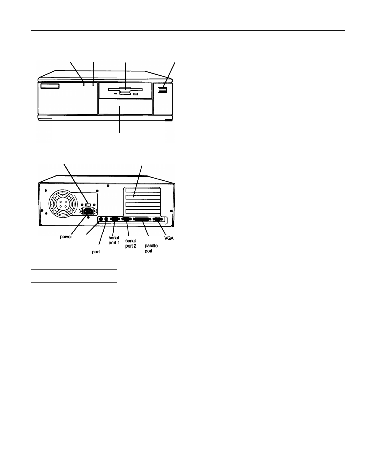
power (SPEED) hard disk
light
115/230 VAC switch
.
inlet port
access light
bay for hard disk, diskette, tape,
CD-ROM, or other drive
keyboard
mouse
diskette
drive
option card slots
Computer Specifications
CPU and Memory
32-bit CPU
System speed
4SX/33: Intel® i486SX, 33 MHz
microprocessor; can be replaced with
optional 487SX/33 or ODP486-33
OverDrive™ processor
4DX2/50: Intel i486DX2, 50 MHz
microprocessor; supports future Intel
OverDrive processor
4DX2/66: Intel i486DX2, 66 MHz
microprocessor; supports future Intel
OverDrive processor
High, low, and automatic speeds available;
high speed is CPU-dependent (33, 50, or
66 MHz), low speed is simulated 8 MHz,
automatic speed switches from high to low
only for diskette drive access; speed
selection through SETUP, keyboard
command, or ESPEED program; 0 wait
state memory access at high speed
power
button
Memory
4MB RAM standard soldered on main
system board; expandable using 1MB,
4MB, 16MB, or 64MB SIMMs to 128MB
(maximum); SIMMs must be 36bit,
fast-page mode type with 70 ns (or faster)
access speed
ROM
128KB ROM containing system BIOS and
video BIOS; 64KB ROM containing SETUP
code
Video RAM
Shadow RAM
1MB video RAM on main system board
Automatic shadowing of system and VGA
BIOS ROM into RAM; shadow RAM
address control selectable through SETUP
Cache
8KB of internal cache (built into the
microprocessor); cache testing and address
control selectable through SETUP
Virtual Cache
Epson proprietary VirtualCache™ feature
automatically creates a “virtual cache”
buffer the size of maximum system
memory
Math
coprocessor
Clock/calendar
On 4DX2/50 and 4DX2/66 systems, math
coprocessor built into the microprocessor
Real-time clock, calendar, and CMOS
RAM on main system board; separate
battery backup
\
monitor
port
Controllers
Video
Chips and Technologies Wingine™ P64200
VGA controller on main system board;
provides resolutions of 800 x 600 x 64K
colors and up to 1024 x 768 x 256 colors
Diskette
Controller on main system board supports
up to two diskette drives or one diskette
drive and one tape drive
Hard disk
Interface on main system board supports
up to two IDE hard disk drives with
built-in controllers
Interfaces
Monitor
VGA interface built into main system
board for analog or multifrequency VGA
monitor; 15-pin, D-shell connector
Parallel
One standard 8-bit parallel, bidirectional
interface built into main system board;
port assignment and I/O address
selectable through SETUP; 25-pin, D-shell
connector
7/27/93
EPSON Progression 4-1
Page 2

EPSON Progression 4
Serial
Keyboard
Mouse
Option slots
Speaker
Alternate VGA
Mass Storage
Two RS-232C, programmable,
asynchronous interfaces built into main
system board; port assignment and I/O
addresses selectable through SETUP;
9-pin, D-shell connectors
PS/2 compatible keyboard interface built
into main system board; keyboard speed,
delay, and num lock settings selectable
through SETUP; 6-pin, mini DIN connector
PS/2 compatible mouse interface built into
main system board; 6-pin, mini DIN
connector
Four standard 16-bit (or 8-bit) I/O
expansion slots; ISA compatible; 8 MHz
bus speed
Internal; operation controllable through
SETUP and volume selectable by software
IBM compatible VGA pass-through
interface built into main system board;
26-pin connector
Three drives maximum (two horizontal
mounts and one vertical mount),
configurable using the following:
Keyboard
Detachable; two-position height;
101 sculpted keys; numeric/cursor control
keypad; four-key cursor control keypad;
12 function keys
Power Supply
Type
Input ranges
145 Watt, fan-cooled
90 to 132 VAC and 180 to 264 VAC, switch
selectable voltage
Maximum
+5 VDC at 18 Amps, +12 VDC at 4.0
outputs Amps, -5 VDC at 0.3 Amps, -12 VDC at
0.3 Amps
Frequency 47 to 63Hz
Cables Two to main system board; four to mass
storage devices
Option Slot Power Limits
Maximum current
For each slot
For all four
slots
+5 volts
7 Amps 1.5 Amps 0.3 Amps
16 Amps
+12 volts -5 Volts and -12 Volts
3 Amps 0.3 Amps
Environmental Requirements
Condition Operatlng range
Horizontal
mounts
Vertical
mount
Diskette drives
Hard disk
drives
Other devices
Up to two externally-accessible,
half-height horizontal mounts; each
horizontal bay can accommodate one
form factor diskette, tape,
CD-ROM, or other drive, or one 3M-inch
form factor hard disk, diskette, tape,
CD-ROM, or other drive with
mounting frames attached
One internal third- or half-height vertical
mount; vertical bay can accommodate one
form factor hard disk or other
drive
5.25-inch, 1.2MB (high-density)
3.5 inch, 1.44MB (high-density)
form factor hard disk drive(s), up
to half-height size; the first mounted
vertically, second mounted horizontally
Half-height tape drive, CD-ROM drive, or
other storage device;
or
form factor with
form factor
mounting frames attached
to
Temperature
Humidity 20% to 60%
condensing)
Maximum
wet bulb
Acoustical
noise
(-100 to 3,000 m)
37.4 dB(A)
F
to
Physical Characteristics
Width 14.8 inches (370 mm)
Depth
16.5 inches (412 mm)
Height 4.8 inches (120 mm)
weight
16.7 lb (7.6 kg),
without keyboard
EPSON Progression 4-2
7/27/93
Page 3
EPSON Progression 4
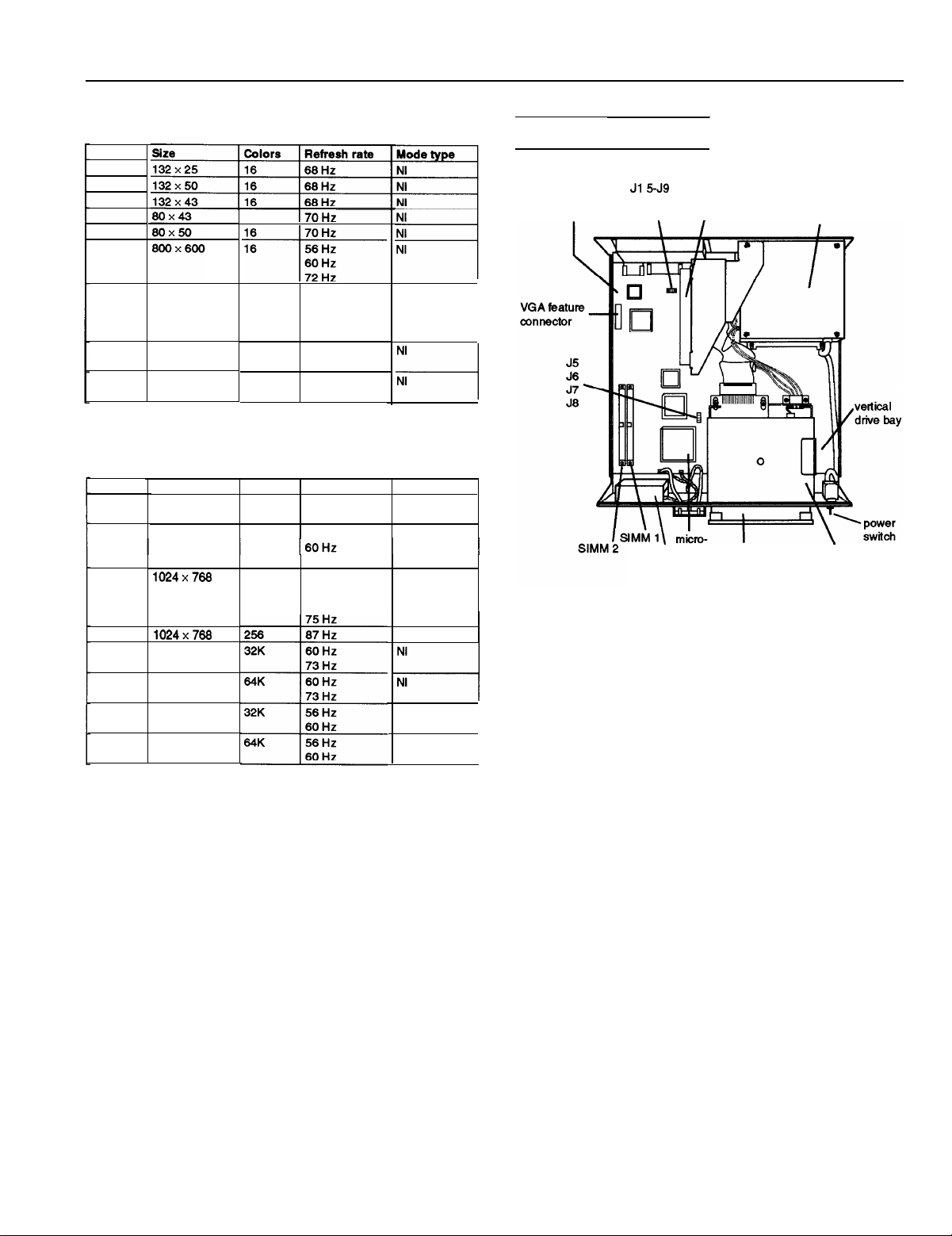
Extended VGA Modes
Mode
60
61
62
64
65
6A/70
72
79
7c 800x600
1024x766
640 x 480
NI = Non-interlaced
I = Interlaced
Wingine Modes
Mode
30
32
34
Size
640x480
800x600
16
16
256 60
256 56
Colors
256
256
256
60
70
72
75
73
60
Refresh rate Mode type
60 Hz
73 Hz
56 Hz
72 Hz
60 Hz
70 Hz
72 Hz
Hz
Hz
Hz
Hz
Hz
Hz
Hz
Hz
NI
NI
NI
NI
NI
Major Subassemblies
main system
board
option board
riser card
\
I
processor diskette
\
speaker
drive
power supply
horizontal
drive bays
36
40 640 x 480
41
42
43 800x600
640 x 480
800x600
NI = Non-interlaced
I = Interlaced
NI
NI
I
NI
I
5/3/93
EPSON Progression 4-3
Page 4

EPSON Progression 4
Main System Board Diagram
alternate
VGA feature
connector
VGA video
108
1
131
PI
parallel
u97
103
El
n
In
102
El
100
El
r-l
serial 2
In
serial 1
u12
cl
keyboard
, ,
option board
riser card
FDD
connector
HDD
connector
SIMM2
u75
u77
an
u79
L13
u53
u54
u57
u59
u37
q
0
EPSON Progression 4-4
5/3/93
Page 5

EPSON Progression 4
Connector Pin Assignments
Parallel Port Connector (CN5)
pin 13
I
pin 25
Parallel Port Connector Pin Assignments
Pin
Signal
Strobe
1
Data 0
2
Data
3
4
5
6
7
9
*Active bw
1
Data
2
Data
3 14
Data
4 15 Error* 24
Data
5 16
Data
6 17 Select in’
Data
7
Serial Port Connectors
Pin
10
11
12 PE
13
18
pin 1
Signal
Busy 20
Auto’
Signal ground
and
pin 1
I
14
pin 5
Pin
19
21
22
23
25
Signal
Signal ground
Signal ground
Signal ground
Signal ground
Signal ground
Signal ground
Signal ground
VGA Port Connector (CN2)
pin 5
pin 10
pin 15
VGA Port Connector Pin Assignments
VGA Feature Connector
pin 1
pin 2
VGA Feature Connector Pin Assignments
pin 1
pin 6
pin 11
pin 25
pin 26
pin9
Serial Port Connector Pin Assignments
Pin
1
Data carrier deted
2
Receive data
3 Transmif
4
5
data
Data terminal ready
Not used
Keyboard Connector
Pin
Signal
6
Data set ready
7
Request to send
Clear to send
9
Ring indicator
and
Mouse Connector
pin 6 pin 5
Pin
5
6
pin 1
Signal
VDC (fused)
Reserved
pin 2
Caution
Although the keyboard and mouse connectors are
physically identical, they cannot be used interchangeably.
Keyboard and Mouse Connector Pin Assignments
Pin
Signal
Data
1
2 I Reserved
3
Ground
‘Active bw
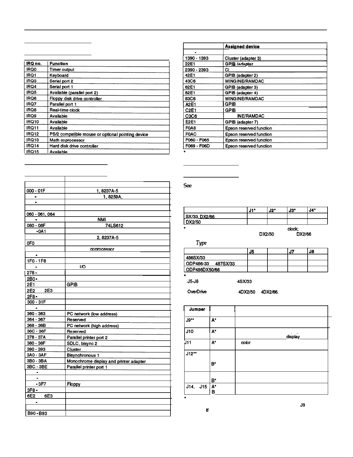
DMA Assignments
5/3/93
EPSON Progression 4-5
Page 6
EPSON Progression 4
Hardware Interrupts
System I/O Address Map
Hex address*
020
021
022
024
040-043
070
071 (CMOS)
OAO
OAl
OCO-ODF
OF1
OF8
OFF
200
207
27A
2DF Alternate enhanced
and
2FF
348
357
3C0
3CF
3D0
3DF
3F0
3F7
3FF
and
793
790
AE2 and AE3
Assigned device
DMA
controller
Interrupt controller
Epson resewed function
Timer, 8254-2
8042 (Keyboard and mouse)
Real-time clock
DMA page register, 74LS812
Interrupt controller 2, 8259A
DMA controller
Clear math coprocessor busy
Reset math coorocessor
Math coprocessor
Hard disk drive
Game
Parallel printer port 3
(adapter 0)
Data acquisition (adapter 0)
Serial port 2
Prototype card
DCA 3278
Enhanced graphics adapter
Color/graphics monitor adapter
Serial
port
Data acquisition (adapter 1)
Cluster (adapter
Data acquisition (adapter 2)
Cluster (adapter 2)
8237A-5
(non-maskable interrupt
graphics
1
1)
master
adapter
mask)
Hex address*
EE2
EE3
A2El
Recommended addresses for installing devices
Data acquisition (adapter 3)
.
luster (adapter 4)
WING
1)
(adapter 5)
(adapter 8)
Jumper Settings
the illustration on page 3 for the location of the jumpers
on the main system board.
CPU Speed Jumper Settings
CPU speed
(25 MHz)
Factory setting according to processor external speed
these jumpers unless you replace the
CPU
CPU type*
Factory-set according to system type. You need to change jumpers
microprocessor chip and install a new one, or if you install a future
Jumper Settings
processor in the
A A
B B
B
A A
A
B
A
system and you remove the original
or
B
A
chip with a
B
A
B
Other Jumper Settings
JumDer
number
J13
Factory setting
“To use a mouse connected to a port on an option card, set
J12 to A.
stick) to the option card port, set both jumpers to A.
Jumper
setting
B
B
B
A
A
you connect another type of pointing device (such as a joy
Function
Enables the built-in mouse connector
Disables the built-in mouse connector
Enables the built-in VGA display adapter
Disables the built-in VGA display adapter
A color monitor is installed
A monochrome monitor is installed
Enables a mouse or other pointing device
connected to an option card
Disables a mouse or other pointing device
connected to an option card
Disables the password
Enables the password
Reserved
A
A
do not change
chip.
B
A
B
to B and
,
EPSON Progression 4-6
5/3/93
Page 7

EPSON Progression 4
Processor Chips
If you have the 4SX/33 system, you can install an Intel
OverDrive processor
or a
microprocessor (with built-in math coprocessor) on the main
system board. Installing an OverDrive processor effectively
doubles the internal clock speed of the computer’s
microprocessor; future OverDrive processors may be
available for the 4DX2 /50 and 4DX2 /66 systems.
SIMM Installation
There are two SIMM sockets on the main system board. To
increase the amount of memory in the computer up to
128MB, you can install 36-bit, fast-page mode SIMMs that
operate at an access speed of 70 ns or faster, with a capacity
of 1MB, 4MB, 16MB, or 64MB.
The following table shows the possible SIMM configurations;
do not install memory in any other configuration. Make sure
that both SIMMs operate at the same speed. There is 4MB of
memory soldered onto the main system board.
SIMM Configurations
SIMM 1
Total memory
4MB *
5MB
Hard Disk Drive Types
The table below lists types of hard disk drives you can use in
the computer. Check this table and your hard disk manual to
find the correct type number(s) for the hard disk drive(s)
installed in the computer. You need to enter the type
number(s) when you set the hard disk drive configuration in
the SETUP program.
Hard Disk Drive Types
Type
no. ( )
1
2
3
4
5
6
7
a
9
la20
615
940 8
615
462
733
Landing Sectors Size’
6
6
4
a
5
512
512
256
me (SEC) (In
615
17
940
17
940
17
615
17
511
17
17
la20
46
20
1112
ST-325A
I
I
l *
128MB
Standard soldered memory
‘*When SIMM is available
This memory configuration disables the 4MB of soldered memory
I
5/3/93
977
547 38
760
979
1022
1022
33
17
39
17
34
36
34
17
40
40
al
115
al
137
42
40
26
27
29
30
a
7 300
5 466
36 548 a
761
40
Qao IO
41
1022
42 1022
43
1024
44 828
45 1024
46 615
l
Actual size when formatted may be slightly different than the size listed
a
none
5
5
a
512
none
5 512 1023 17
a 128
on the drive label.
Hard disk drive supported in translate mode
Epson drives
EPSON Progression 4-7
Page 8

EPSON Progression 4
If the computer has an Epson 120MB or 240MB hard disk
drive, select the appropriate type number from the table
below.
Epson Hard Disk Drive Types
Type number Epson hard disk drive
39
34 240MB
120MB
Installation/Support Tips
Power
The computer has an input voltage selection switch on the
back panel to select between 115V, for USA and Canadian
use, and 230V, for use in other countries.
Mouse and Keyboard
When connecting the mouse and keyboard to the computer,
be careful to plug them into the proper ports. Although the
ports are physically identical, they are not interchangeable,
and you can damage the main system board if you plug the
connectors into the wrong ports.
Installing Diskette Drives
Make sure that the drive type has been correctly selected in
the SETUP program.
Installing Hard Disk Drives
It is recommended that a 16-bit, AT-type hard disk
controller be used if you are installing a drive that cannot
use the embedded IDE interface. If you install a non-IDE
hard disk drive and controller card, you need to use the
SETUP program to disable the built-in IDE hard disk drive
interface.
See the hard disk drive type tables on page 7 and use the
SETUP program to enter the correct type number(s) for
the hard disk drive(s) installed in the computer. (Also be
sure to use the SETUP program to set the hard disk drive
configuration if you install or remove a hard disk drive.)
You can select a type number that matches the parameters
for the drive or a type number with parameters having
lesser values, as long as they do not exceed the maximum
capacity (in MB) of the drive. If there is no match for the
drive, you can press Enter and then F2 at the Hard disk 1
or 2 option and enter the drive’s exact parameters.
If you are using a copy-protected program that does not
require a key disk but requires a special procedure to
install it on a hard disk, set the speed to low while you
install the program. Then set the speed to high while you
load and run the program. If this does not work, try
installing and loading the program at low speed and then
change to high speed to run it.
You can change the processor speed using the SETUP
program, the ESPEED program, or keyboard commands.
See the User’s Guide and Setup
Guide
for more information.
Password
Make sure that you do not forget the password you set. If you
do, you must disable it by setting jumper J13 on the main
system board to position A.
Information Reference List
Engineering Change Notices
None.
Technical Information Bulletins
None.
Product Support Bulletins
None.
Related Documentation
TM-PROGRSS4
PL-PROGRSS4
SPKPROGRSS4
400192900
400193000
400193100
EPSON Progression 4 Service Manual
EPSON Progression 4 Parts Price List
EPSON Progression 4 Self Paced Kit
EPSON Progression 4 Setup Guide
EPSON Progression 4 User’s Guide
EPSON VGA Utilities Guide for Wingine
based products
Software Problems
If you are using a copy-protected program that can run
only on a diskette or that requires a key disk, try to load
the program at high speed. If you can’t load the program
at high speed, set the processor speed to automatic.
EPSON Progression 4-8
5/3/93
 Loading...