

Page 1

®
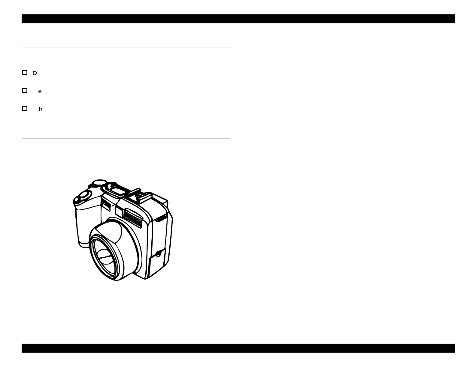
Digital Still Camera
EPSON PhotoPC 850Z
Page 2

Notice:
All rights reserved. No part of this manual may be reproduced, stored in a retrieval system, or transmitted in any form or by any means,
electronic, mechanical, photocopying, recording, or otherwise, without the prior written permission of SEIKO EPSON CORPORATION.
The contents of this manual are subject to change without notice.
All effort have been made to ensure the accuracy of the contents of this manual. However , shoul d any errors be detected, SEIKO EPSON
would greatly appreciate being informed of them.
The above not withstanding SEIKO EPSON CORPORATION can assume no responsibility for any errors in this manual or the consequences
thereof.
EPSON is a registered trademark of SEIKO EPSON CORPORATION.
General Notice: Other product names used herein are for identification purpose only and may be trademarks or registered trademar ks of their
respective owners. EPSON disclaims any and all rights in those marks.
Copyright © 1999 SEIKO EPSON CORPORATION. Printed in Japan.
Page 3

PRECAUTIONS
Precautionary notations throughout the text are categorized relative to 1) Personal injury and 2) damage to equipment.
W ARNING
The precautionary measures itemized below should a lways be observed when performing repair/maintenance procedures.
Signals a precaution which, if ignored, could result in
serious or fatal personal injury. Great caution should be
exercised in performing procedures preceded by a
WARNING heading.
CAUTION
Signals a precaution which, if ignored, could result
in damage to equipment.
DANGER
1. ALWAYS DISCONNECT THE PRODUCT FROM THE POWER SOURCE AND PERIPHERAL DEVICES PERFORMING ANY MAINTENANCE
OR REPAIR PROCEDURES.
2. NOWORK SHOULD BE PERFORMED ON THE UNIT BY PERSONS UNFAMILIAR WITH BASIC SAFETY MEASURES AS DICTATED FOR
ALL ELECTRONICS TECHNICIANS IN THEIR LINE OF WORK.
3. WHEN PERFORMING TESTING AS DICTATED WITHIN THIS MANUAL, DO NOT CONNECT THE UNIT TO A POWER SOURCE UNTIL
INSTRUCTED TO DO SO. WHEN THE POWER SUPPLY CABLE MUST BE CONNECTED, USE EXTREME CAUTION IN WORKING ON
POWER SUPPLY AND OTHER ELECTRONIC COMPONENTS.
WARNING
1. REPAIRS ON EPSON PRODUCT SHOULD BE PERFORMED ONLY BY AN EPSON CERTIFIED REPAIR TECHNICIAN.
2. MAKE CERTAIN THAT THE SOURCE VOLTAGES IS THE SAME AS THE RATED VOLTAGE, LISTED ON THE SERIAL NUMBER/RATING
PLATE. IF THE EPSON PRODUCT HAS A PRIMARY AC RATING DIFFERENT FROM AVAILABLE POWER SOURCE, DO NOT CONNECT IT
TO THE POWER SOURCE.
3. ALWAYS VERIFY THAT THE EPSON PRODUCT HAS BEEN DISCONNECTED FROM THE POWER SOURCE BEFORE REMOVING OR
REPLACING PRINTED CIRCUIT BOARDS AND/OR INDIVIDUAL CHIPS.
4. IN ORDER TO PROTECT SENSITIVE MICROPROCESSORS AND CIRCUITRY, USE STATIC DISCHARGE EQUIPMENT, SUCH AS ANTISTATIC WRIST STRAPS, WHEN ACCESSING INTERNAL COMPONENTS.
5. REPLACE MALFUNCTIONING COMPONENTS ONLY WITH THOSE COMPONENTS BY THE MANUFACTURE; INTRODUCTION OF
SECOND-SOURCE ICs OR OTHER NONAPPROVED COMPONENTS MAY DAMAGE THE PRODUCT AND VOID ANY APPLICABLE EPSON
WARRANTY.
Page 4

PREFACE
This manual describes basic functions, theory of el ectrical and mechanical operations, maintenance and repair procedures of PhotoPC 850Z. The
instructions and procedures included herein are intended for the experienced repair technicians, and close attention should be given to the
precautions on the preceding page. Chapters are organized as follows:
CHAPTER 1. PRODUCT DESCRIPTIONS
Provides a general overview and specifications of the product.
CHAPTER 2. OPERATING PRINCIPLES
Describes the theory of electrical and mechanical operations of the product.
CHAPTER 3. TROUBLESHOOTING
Provides the step-by-step procedures for troubleshooting.
CHAPTER 4. DISASSEMBLY AND ASSEMBLY
Describes the step-by-step procedures for disassembling and assembling the
product.
CHAPTER 5. ADJUSTMENT
Provides adjusting procedures.
CHAPTER 6. MAINTENANCE
Provides preventive maintenance procedures.
APPENDIX
Provides the following addition information for reference:
- Circuit Boards Component Layout
- Exploded Diagrams
- Circuit Schematics
Page 5

Revision Status
Revision Date of Issue
A September 16, 1999 First Release
Description
Page 6

Table of Contents
Product Description
Features ....................................................................................................... 10
Product Features..................................................................................... 10
Exterior......................................................................................................... 12
Weight and Dimension ............................................................................ 12
Functional Specifications.............................................................................. 13
Images..................................................................................................... 13
Optics..................................................................................................13
Others .................................................................................................14
Shooting Mode ........................................................................................ 15
Memory ................................................................................................... 16
Users Guide Function and Others........................................................... 16
GUI Menu Operation (Summary) ............................................................ 18
SETUP Mode ........................ ...... ....... ...... ....... ...... ....... ...... ....... ...... ....18
VF Mode (LCD Monitor Off) ................................................................19
Monitor Shooting Mode......................................... ....... ...... ....... ...... .... 1 9
Confirmation Image.............................................................................21
Special Shooting Mode.......................................................................21
Playback Mode....................................................................................21
Time Required for Disposing Images...................................................... 22
File Size and the Number of Pictures...................................................... 22
File Size ..............................................................................................22
Average Number of Pictures Saved into the
External Memory...................................................................22
Interface Connectors and Others............................................................ 23
Serial Interface....................................................................................23
Power...................................................................................................... 24
Battery Life .............................................................................................. 24
Automatic Shutting Down Mode.............................................................. 25
Visual Guidance and Switch Function.......................................................... 26
Information Indicated on the Control LCD............................................... 26
Switch Function...................................................................................26
LED Condition.....................................................................................27
Control LCD ........................................................................................27
LCD Monitor.......................................................... ..............................28
Setting Items ........................................................................................... 29
Full Auto Shooting Mode.....................................................................29
Program Mode ....................................................................................30
Manual Mode ......................................................................................31
Attach Products............................................................................................ 32
Attach Cable............................................................................................ 32
DOS/V Connector Cable.....................................................................32
Macintosh Connector Cable....................... ...... ....... ............................32
USB Interface Cable ...........................................................................33
Interface Cable for Video and Audio...................................................33
Other Attached Products......................................................................... 33
Option........................................................................................................... 34
Standard Option...................................................................................... 34
Environmental Conditions ............................................................................ 35
Safety and Others ........................................................................................ 36
Inhibitions and Cautions ............................................................................... 37
Operating Principles
Overview ...................................................................................................... 39
Operating Principles of Circuit Boards ......................................................... 40
CA1 Circuit Description ........................................................................... 41
IC903 (CCD) .......................................................................................41
IC902 (H Driver) and IC904 (V Driver)................................................43
Lens Drive Block................................. ....... ...... ...................................44
CA2 Circuit Description ........................................................................... 45
Circuit Description...............................................................................45
Operation Outline................................................................................47
LCD Block........................................... ....... ...... ....... ...... ....... ...... .........47
PW1 Power Circuit Description............................................................... 48
Outline.................................................................................................48
Switching Controller (IC501)...............................................................49
Shot-Circuit Protection Circuit.............................................................49
Digital 5V and Analog System Power Output .....................................49
Digital 3.25V System Power Output....................................................49
Page 7

LCD System Power Output................................................ ....... ...... ....49
Backlight Power Supply Output...........................................................49
PW1 Strobe Circuit Description............................................................... 50
Charging Circuit ..................................................................................50
Light Emission Circuit ..... ....... ...... ....... ............................................. ....51
SY1 Circuit Description ........................................................................... 52
Configuration and Functions...............................................................52
Internal Communication Bus...............................................................54
Key Operation .....................................................................................55
Power Supply Control .........................................................................55
Troubleshooting
Overview....................................................................................................... 58
Error Indications ...................................................................................... 58
Trouble Shooting .......................................................................................... 58
Camera Has No Power ........................................................................... 58
No Shooting............................................................................................. 59
Image Cannot be Taken.......................................................................... 59
Disassembly and Assembly
Overview....................................................................................................... 61
Precautions ............................................................................................. 61
Equipment and Tools .............................................................................. 62
Diassembly and Assembly ........................................................................... 64
Removal of Cabinet Parts ....................................................................... 65
Discharging Electricity from Capacitor ................................................66
Removal of SY1 Board and Holder Battery............................................. 67
Removal of SY2 Board, LCD, and CA2 Board........................................ 68
Removal of PW1 Board and CA1 Board ................................................. 69
Assembly Procedure .................................................................................... 70
Assembly of Lens Assy........................................................................... 70
Assembly of Lens VF .............................................................................. 71
Installation of Lens Assy.......................................................................... 72
Installation of CA2 Board......................................................................... 73
Installation of LCD................................................................................... 74
Installation of Spacer Monitor..............................................................74
Installation of LCD...............................................................................75
Installation of Door Monitor.................................................................76
Installation of Microphone and SY2 Board.............................................. 77
Installation of Speaker............................................................................. 78
Installation of Holder Chassis B .............................................................. 79
Installation of Holder Battery................................................................... 80
Assembly of Cover Top........................................................................... 81
Installation of SY1 Board......................................................................... 81
Installation of Unit Dial and Cover Top.................................................... 82
Assembly of Cabinet Front...................................................................... 83
Assembly of Lens Barrier....................................................................83
Installation of Cabinet Back..................................................................... 86
Installation of Cabinet Front .................................................................... 87
Installation of Door Card ......................................................................... 88
Adjustment
Overview ...................................................................................................... 90
Adjustment Items and Order ................................................................... 90
Getting Ready for Adjustment................................................................. 90
System Requirements.........................................................................90
Installation of Calibration Software .....................................................90
Color Viewer .......................................................................................90
Connecting Camera to Computer ........................................................... 91
Adjustment ................................................................................................... 92
Initialization Operation............................................................................. 92
Positions for Measuring and Adjusting on
PW1 Board.................................................................................... 93
Preparation .........................................................................................93
IC501 Oscillation Frequency Adjustment............................................93
5.1V (A) Voltage Adjustment...............................................................93
3.25V (D) Voltage Adjustment ............................................................93
12.4V (L) Voltage Adjustment.............................................................94
7.7V (L) Voltage Adjustment...............................................................94
AWB Adjustment ..................................................................................... 95
Color Matrix Adjustment.......................................................................... 96
CCD Defect Detection Adjustment.......................................................... 96
Lens Adjustment ...... ....... ...... ...... ....... ...... ....... ...... ....... ...... ....... .............. 97
LCD Panel Adjustment [CA2 Board (Side A)] ......................................... 98
LCD H AFC Adjustment ......................................................................98
LCD RGB Offset Adjustment ..............................................................99
Page 8

LCD Gain Adjustment ........................ ...... ....... ...... ....... .......................99
LCD Blue Brightness Adjustment......................................................100
LCD Red Brightness Adjustment ......................................................100
Uploading Firmware .............................................................................. 101
Maintenance
Overview..................................................................................................... 103
Check Points ......................................................................................... 103
Appendix
Connection Among Boards......................................................................... 106
Circuit Boards Component Layout.............................................................. 108
Exploded Diagram...................................................................................... 113
Circuit Schematics...................................................................................... 116
Siemens Star Chart .................................................................................... 124
Page 9

PRODUCT DESCRIPTION
Page 10

EPSON PhotoPC 850Z Revision A
Power Saving Function:
1.1 Features
1.1.1 Product Features
HyPict Mode:
1984 x 1488 (HyPict)
1984 x 744 (Panorama HyPict)
Quick Taking Mode:
Intervals are less than 1.5 seconds.
External Memory:
Compact Flash memory card (CF card) available.
Automatic shut-down mode
(Setting time: 10 sec., 30 sec., 1 min., 3 min., and 5 min.)
Power Source:
Four Ni-MH batteries
Interface:
USB, DOS/V serial, and Mac serial
Video Output:
NTSC and PAL (different model)
Image and Sound File Format:
Exif 2.1 compatible
NOTE:
Cannot use internal ROM for image data.
Shooting Modes:
Continuous Shooting Mode, Interval Shooting Mode,
VF Shooting Mode (using the optical view finder, rear LCD-monitor off),
Monitor Shooting Mode (using the LCD-monitor), and Panorama, Macro,
and Monochrome Modes
Manual Exposure Mode:
Shutter speed setting: 4 - 1/800 (66 steps)
Aperture setting: F2.0 - and F11 (Wide), F2.8 and F11 (Tele)
Program Exposure Mode:
Sports Program: High speed shutter mode
Portrait Program:
Wide: Aperture F2.0 and shutter speed AE
Tele: Aperture F2.8 and shutter speed AE
Landscape Program: Aperture F11 and shutter speed AE
Normal Program: AE
White Balance:
User custom mode, fixed mode (5200K), and auto
Voice Annotation:
Capable of recording a voice (3 sec., 5 sec., and 10 sec.)
Playback Mode:
Slide show, play back mode, after recording, and playing voice
Recording Rule:
DCF (Design rule for camera file system)
HARDWARE FEATURES
High Resolution CCD:
2.0 Mega pixels CCD (Interline Transfer)
High Image Quality:
2.5 x VGA (1600 x 1200 pixels, 24bit color)
Full Specifications Built-in:
2-inch dual lighting source color TFT LCD monitor
(Low-temperature poly-silicon TFT-LCD)
View Finder, microphone, speaker, and hot synch flash shoe
Image Quality:
1600 x 1200 pixels (Super-Fine) low compression
1600 x 1200 pixels (Fine) high compression
640 x 480 pixels (Standard)
1600 x 600 pixels (Panorama, Super-Fine)
1600 x 600 pixels (Panorama, Fine)
640 x 240 pixels (Panorama, Standard)
Product Description Features 10
Page 11

EPSON PhotoPC 850Z Revision A
SOFTWARE FEATURES (TWAIN DRIVER, STANDALONE UTILITY)
Function Summary:
Standalone Utility / TWAIN Driver / OLE2 Server
Supported OS:
Win95 and later, WinNT 4.0 and later, and Macintosh System 7.5 and later
are supported.
NOTE:
68K Mac is not supported.
Function Details:
- Downloading pictures and voices from camera to PC
- Uploading pictures and voices from PC to camera
- Rotating images
- Auto photo fine function
- Showing thumbnail images
SOFTWARE FEATURES (DIRECT PRINTING)
Function Summary:
Image print, index print, album print, sticker print
Information (on the image) print function, auto photo fine function
(automatically applies to all images).
Printer:
EPSON STYLUS PHOTO, STYLUS PHOTO 700, STYLUS PHOTO EX,
STYLUS PHOTO 750, STYLUS COLOR 740, STYLUS PHOTO 1200
OPTIONS
AC Adapter:
EU-40 (Input: 100-240V, Output: DC7.0V, 2.0A)
Ni-MH Battery Charger:
EU-38 (Input: 100-240V)
Ni-MH Battery:
EU-24 (1500mAh)
Paper Size (T.B.D):
A3 (Glossy Film, Photo Paper, Glossy Paper, Glossy Sticker)
A4 (Glossy Film, Photo Paper, Glossy Paper, Glossy Sticker)
Post Card (Photo Paper, Glossy Paper)
A6 (Photo Paper)
Printing Functions:
Color, monochrome, sepia, and blue print
Product Description Features 11
Page 12
EPSON PhotoPC 850Z Revision A
1.2 Exterior
1.2.1 Weight and Dimension
Dimension:
126 x 82 x 72 (mm)
Weight:
400g: (without batteries, strap and CF card)
Others:
Tripod mountable
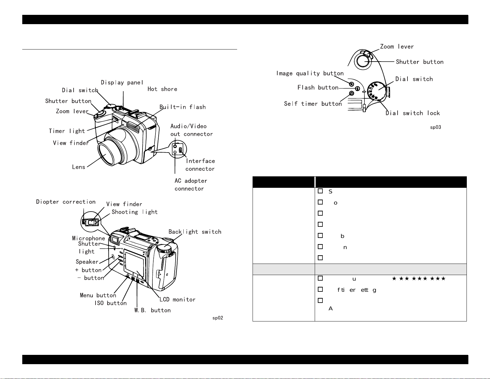
EXTERNAL VIEW
Figure 1-1. External View
Product Description Exterior 12
Page 13
EPSON PhotoPC 850Z Revision A
1.3 Functional Specifications
1.3.1 Images
RECORDING RULE
DCF (Design rule for camera file system)
THUMBNAIL RESOLUTION
160 x 120 pixels
IMAGE RESOLUTION
1984 x 1488 pixels (
1984 x 744 pixels (
1600 x 1200 pixels (
1600 x 1200 pixels ( Fine)
1600 x 600 pixels (
1600 x 600 pixels ( Panorama Fine)
H
Hypict)
H
Panorama Hypict)
Super Fine)
Panorama Super Fine)
LENS
f = 6.5 -19.5mm (equivalent to 35-105mm on a camera using 35mm films)
8 elements in 6 groups construction
APERTURE
F2.0-F11 (Wide), F2.8-F11 (Tele) 1/3EV STEP
VIEW FINDER
Real image optical finder
Visual field covers more than 90% of a capturing image field
Markers indicating a target area for foreclosing
Markers indicating the picture plane of 80cm subject distance
Diopter collecting
FOCUS
Auto Focus / Manual Focus
640 x 480 pixels ( Standard)
COLOR
24 bit color or monochrome
FOCUSING RANGE
0.2 - 0.5 (m) (Macro mode)
0.5m - ∞ (Normal)
1.3.1.1 Optics
CCD
1/2” color area CCD (2.0 Mega pixels) with complementary filters.
Total pixels: 1688 x 1248 (Effective pixels: 1636 x 1236)
(Real use pixels: 1620 x 1220)
Product Description Functional Specifications 13
Page 14
EPSON PhotoPC 850Z Revision A
SHUTTER
Electronic Iris control shutter with mechanical shutter
1/30 -1/1800 sec (when Flash mode is auto or compulsion is On.)
4 - 1/800 sec (when Flash mode is Off or slow sync. is On.)
NOTE:
Automatic focusing function may not work correctly when taking
photos under bad contrast conditions or low illuminated conditions
(particularly when flash is necessary).
The automatic focusing function is programmed to set the distance
at 1.5m when it cannot measure the correct distance.
1.3.1.2 Others
METERING SYSTEM
Divided brightness measuring programmed AE
(Aperture and shutter speed are variable)
Spot metering programmed AE
(Aperture and shutter speed are variable)
EXPOSURE ADJUSTMENT
WHITE BALANCE
Through the taking lens automatic white balancing
Fixed mode (color temperature: 5200K)
Customizing mode (users’ setting available)
FLASH
Auto, prohibition, compulsion, red-eye reduction, external
Slow synchro mode (night view mode, user select trailing or leading)
FLASH EFFECTIVE RANGE
Macro mode: 0.2 m - 0.8 m
Normal mode: 0.8 m - 3.7 m
NOTE:
It causes over -exp osur e to take ph otos wi th stro be at 0.2 m subjec t
distance on macro-photographic mode.
Manual adjustment possible (-2EV ~ +2EV, 0.5EV / 0.2EV step)
AE temporary lock function
SENSITIVITY
Equivalent to ISO 100 (normal mode)
Equivalent to ISO 200 (high sensitivity mode)
Equivalent to ISO 400 (super high sensitivity mode)
Product Description Functional Specifications 14
Page 15
EPSON PhotoPC 850Z Revision A
1.3.2 Shooting Mode
LCD DISPLAY
Live picture shown on the LCD monitor (refresh rate 1/30 sec)
Visual field covers more than 98% of a capturing image field.
SELF TIMER
10 sec timer (fixed)
(Slow blinking for the first 8 sec, and fast blinking for the last 2 sec.)
MACRO
Working Range: 0.2m- 0.5m
QUICK TAKING MODE
Pictures taken are temporally saved into the DRAM in order to provide the
shortest intervals between shooting. After capturing photos, photo files are
transferred from DRAM to the Compact Flash Memory Card.
Interval time is approximately 1.5 sec.
(When taking pictures in (
) Super Fine mode without flash charge.)
DIGITAL ZOOM
Digital x2 zoom function
Available at any picture size; however, taking pictures in HyPict mode
needs longer time for processing than the others
(simple complement).
PANORAMA
Size: 1600 x 600 pixels (
/
Super Fine / Fine)
MONOCHROME
Size: 1600 x 600 pixels (
/
Super Fine / Fine)
INTERVAL SHOOTING
Minimum Interval: 10 sec. (except HyPict or voice recording setting)
Maximum Interval: 24 hours
Interval Step: 1 sec.
PROGRAM SHOOTING FUNCTION
Writing speed to the CF card is approximately 130KB/sec.
The quick taking function is available until the 8M DRAM becomes full of
photo files. (The number of image files is limited to 10.)
Sports mode, portrait mode, landscape mode, and normal mode
CONTINUOUS SHOOTING
VGA (640 x 480): Approx. 2 images/sec.
Full-pixels (/
A capacity of DRAM for continuous shooting is 4.0 MB.
Flash: Forcibly change to no flash mode.
1600 x 1200): Approx. 1 image/ sec.
Product Description Functional Specifications 15
Page 16

EPSON PhotoPC 850Z Revision A
1.3.3 Memory
INTERNAL RAM
8 MB
INTERNAL ROM
4 MB (only for program 2MB)
EXTERNAL MEMORY
Compact Flash Memory Card
PC-DOS format: 512B/Sector
12bit FAT (up to 15MB)/ 16bit FAT
1.3.4 Users Guide Function and Others
LCD MONITOR
2.0” low-temperature poly-silicon TFT color LCD
(110 thousands pixels: 512 x 218 pixels
A visual field covers more than 100% of a capturing image field.
Displaying taken pictures at playback mode, 100% of an image field will be
guaranteed.
BEEP SOUND
Always / shutter / never mode available
SELF TIMER INDICATION
First 8 seconds: slow blinking
Last 2 seconds: high speed blinking
CONTROL LCD PANEL (MONOCHROME DISPLAY)
Indicates the remaining number of images to be taken (in 3 digits).
With the Quick Taking mode ON, the panel indicates the number of images
in the internal RAM (up to 9 images).
Aperture is indicated by half-shutter.
(Only with Program or Manual mode)
Shutter speed is indicat ed by half- shu tter .
(Only with Program or Manual mode)
Indicatde exposure adjustment.
Indicated quality of image (including Monochrome and Hypict)
Product Description Functional Specifications 16
Page 17

EPSON PhotoPC 850Z Revision A
Others
White Balance
Sensitivity
Self Timer Mark
Flash Mode
Battery Warming Mark
LED LOCATED NEXT TO THE VIEW FINDER
Green (On / Blinking / Off)
Red (On / Blinking / Off)
REAR LED (CAMERA CONDITION LED)
Green (On / Blinking / Off)
BUILT-IN CLOCK
Date and time are recorded into the picture files.
Super capacitor keeps track of date and time even during the battery
replacement.
When USB connection is used, the camera does not shut down until its
battery level becomes low.
*Operation on any button is impossible once the above setting time has
passed.
When the AC adapter is connected, the camera shuts down after 15
minutes (Interval shooti ng is OK).
POWER SAVING
Automatic Shut-down Mode
(Setting Time: 10sec, 30sec, 1min, 3min, and 5min)
*Operation on any button is impossible once the above setting has passed.
(Only at shooting mode or playback mode)
In the case of Slide Show, the camera shuts down after replaying a cycle.
With Power Saving Mode Off, the camera does not shut down until its
battery level becomes low.
When connected to PC, the camera shuts down after 1 minutes.
Product Description Functional Specifications 17
Page 18
EPSON PhotoPC 850Z Revision A
1.3.5 GUI Menu Operation (Summary)
DIAL-SWITCH (D-SW)
Dial Switch has the following six functions:
SETUP Mode
VF Mode (LCD off)
Monitor Shooting Mode
Special Shooting Mode
Playback Mode
Option Mode
COMMUNICATION POSSIBLE MODE
This is an optional function mode. Communication is possible even if you forgot
to set the date.
1.3.5.1 SETUP Mode
GENERAL SETTING
CAMERA SETTING
Power Saving Function
10 sec. / 30 sec. / 1 min. / 3 min. / 5 min.
Brightness of the LCD Monitor
-3 / -2 / -1 / 0 / 1 / 2 / 3
Beep Sound
Always / Shutter / None
Voice Annotation
Off / 3 sec. / 5 sec. / 10 sec.
SHOOTING SETTING
Slow Synchro (Trailling / Leading)
Flash Setting (INT / EXT)
White Balance Setting
Color Setting (B/W)
MEMORY SETTING
Selecting a directory
Adding options
Date setting
01/01/1999, 00:00 (Y.M.D. for Japan and China; M.D.Y for others)
Select a shooting mode (Full Auto / Program / Manual)
Setting a shooting function (Normal Mode / Quick Taking Mode)
Formatting the Compact Flash Memory Card
LANGUAGE SETTING
Japanese / English / Italian / Portuguese / German / Spanish / French /
Chinese
Product Description Functional Specifications 18
Page 19
EPSON PhotoPC 850Z Revision A
1.3.5.2 VF Mode (LCD Monitor Off)
This is the shooting mode with LCD monitor off.
FULL AUTO
Flash Setting
Auto / Compulsion / Prohibition / Red-eye reduction
Image Quality Setting
Normal Shooting
//
Quick Shooting
//
Self Timer Function
PROGRAM
Flash Setting
Auto / Comp u ls io n / Pr oh ib i ti o n / Slow Synchro n iza t i on / R e d- ey e r edu ct i on
Image Quality Setting
Normal Shooting
//
Quick Shooting
//
Self Timer Function
Sensitivit y Setting
Standard / High / Super High
White Balance
AUTO / FIX / CUSTOM
Exposure Adjustment
From -2 to +2 (9 steps by 0.5 degree)
H
/
H
/
MANUAL
Flash Setting
Auto / Compulsion / Prohibition / Slow Synchronization / Red-eye reduction
Image Quality Setting
Normal Shooting
//
Quick Shooting
//
Self Timer Fu n c t io n
Sensitivity Setting
Standard / High / Super High
White Balance
AUTO / FIX / CUSTOM
Exposure Adjustment
From -2 to +2 (21 steps by 0.2 step)
H
/
1.3.5.3 Monitor Shooting Mode
This is the shotting mode with the LCD monitor on.
FULL AUTO
Flash Setting
Auto / Compulsion / Prohibition / Slow Synchronization / Red-eye reduction
Image Quality Setting
Normal Shooting
//
Quick Shooting
//
Self Timer Fu n c t io n
H
/
Digital Zoom (x2)
Macro / Panorama
Product Description Functional Specifications 19
Page 20
EPSON PhotoPC 850Z Revision A
Self Timer Fu n c t io n
PROGRAM
Flash Setting
Auto / Comp u ls io n / Pr oh ib i ti o n / Slow Synchro n iza t i on / R e d- ey e r edu ct i on
Image Quality Setting
Normal Shooting
//
Quick Shooting
//
Self Timer Function
Digital Zoom (x2)
Macro / Panorama
Sensitivit y Setting
Standard / High / Super High
White Balance
AUTO / FIX / CUSTOM
Exposure Adjustment
From -2 to +2 (9 steps by 0.5 degree)
Exposure Program
Sports / Portrait / Landscape / Normal
Simple PLAY BACK Mode
Enlargement / Delete / Multi / Sound Play
H
/
Digital Zoom (x2)
Macro / Panorama
Sensitivity Setting
Standard / High / Super High
White Balance
AUTO / FIX / CUSTOM
Exposure Adjustment
From -2 to +2 (21 steps by 0.2 degree)
Manual Exposure
Shutter Speed Settin g
64 steps
Aperture Select
F 2.0 / 2.8 / 4.0 / 5.6 / 8 / 11
Exposure Program
Shutter Priority
Shutter Speed = AE, Aperture
Aperture Priority
Shutter Speed, Aperture = AE
Focus Setting
Except Macro Mode
3 steps + AF
Macro Mode
MANUAL
Flash Setting
Auto / Comp u ls io n / Pr oh ib i ti o n / Slow Synchro n iza t i on / R e d- ey e r edu ct i on
Image Quality Setting
Normal Shooting
//
Quick Shooting
//
H
/
2 steps / AF
Metering System
Divided brightness metering / Spot metering
Product Description Functional Specifications 20
Page 21
EPSON PhotoPC 850Z Revision A
1.3.5.4 Confirmation Image
CONFIRMATION IMAGE
Immediately after shooting, users can delete an image while transferring the
image to the Compact Flash Memory Card, except for the images that are
already recorded.
1.3.5.5 Special Shooting Mode
Use the LCD setting mode to enter the special shooting mode.
“Confirmation image” and “Quick Taking” functions are not operated.
CONTINUOUS SHOOTING
Flash Setting: Prohib iti on
Image Quality Setting (/
Two different image processing speeds
/
(640 x 480 pixels): 2 images / sec.
(1600 x 1200 pixels): 1 image/ sec.
INTERVAL SHOOTING
Interval Time Setting
Except in HyPict or Voice Annotation Mode
10 sec - 24 hour: 1 sec step
HyPict or Voice Annotation Mode
20 sec - 24 hour: 1 sec step
With Micro Drive inserted
20 sec - 24 hour: 1 sec step
Others
10sec - 24 hour: 1 sec step
/
)
1.3.5.6 Playback Mode
NORMAL REPLAY
Image Information
Date
Shutter Speed
Aperture
Flash Mode: Flashing or Non-flashing
W/B Mode
Multi-screen Function
4 images / 9 images are indicated at a stretch.
Lock images
Delete images and sounds
Display the enlarged image (double in size)
After Recording
3 sec. / 5 sec. / 10 sec.
SLIDE SHOW
Slide Interval Time Setting
3 sec. / 5 sec. / 10 sec. / Manual
Pause during the Slide Show
Delete an image from Slide Show
Select / Delete slide images
Rotate images ± 90
Multi-screen Function
4 images / 9 images are indicated at a stretch.
°
Product Description Functional Specifications 21
Page 22
EPSON PhotoPC 850Z Revision A
1.3.6 Time Required for Disposing Images
Table 1-1. Time Required After Shooting (T.B.D)
Image Quality
Standard
Fine
Super Fine
HyPict
NOTE:
Approximate file size:
Shooting Interval
(Normal Shooting)
Less than 2 sec About 1.0 sec Less than 0.5 sec
About 2.6 sec About 1.5 sec About 1.0 se c
About 3.2 sec About 1.5 sec About 1.5 sec
H
About 12 sec. - About 2.0 sec.
Shooting Interval
(Quick Taking
Mode)
(680KB), (340KB), (67KB)
Image Changing
Interval
(Playback Mode)
1.3.7 File Size and the Number of Pictures
1.3.7.1 File Size
A captured image file will be compressed by the JPEG method. The number of
pictures to be taken may vary depending on the complexity of the captured file.
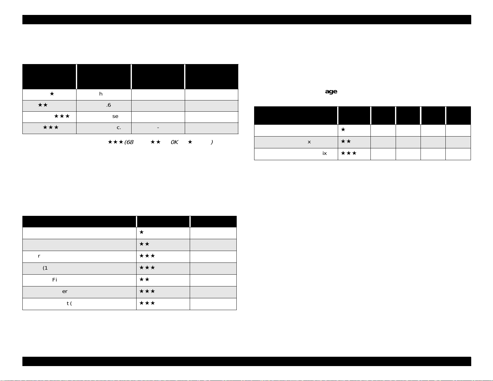
Table 1-2. File Size (TBD)
Image Quality Indicated Marks File Size
1.3.7.2 Average Number of Pictures Saved into the
External Memory
A captured image file will be compressed by the JPEG method. The number of
pictures to be taken may vary depending on the complexity of the captured
image.
Table 1-3. Average Number of Pictures Saved into the
External Memory (Reference Value) T.B.D.
Image Quality
Standard (640 x 480 pixels)
Fine (1600 x 1200 pixels)
Super Fine (1600 x 1 200 p ix els )
Note 1: The number of images that can be taken depends on our measurement
conditions on the assumption that no other files is in an external
memory.
Note 2: A maximum number of images that can be stored in one flash memory
is 999.
Indicated
Marks
8MB 15MB 26MB 24MB
120 250 333 400
24 49 65 78
12 24 32 39
Standard (640 x 480 pixels)
Fine (1600 x 1200 pixels)
Super Fine (1600 x 1200 pixels)
HyPict (1984 x 1488 pixels)
Panorama Fine (1600 x 600 pixels)
Panorama Super Fine (1600 x 600 pixels)
Panorama HyPict (1984 x744 pixels)
H
H
About 60 KB
About 306 KB
About 612 KB
About 700 KB
About 153 KB
About 306 KB
About 350 KB
Product Description Functional Specifications 22
Page 23
EPSON PhotoPC 850Z Revision A
1.3.8 Interface Connectors and Others
VIDEO OUTPUT
NTSC, PAL
INLET FOR DC POWER SUPPLY
DC power is supplied from AC adapter (7.0V), EIAJ Type2 ø4.4
SERIAL INTERFACE
14-pin dual line terminal
Recognition of connection by detecting GND
TCX3080 made by Hoshiden Corporation
COMPACT FLASH CARD SLOT
Compact flash card interface
EXTERNAL FLASH
Hot Sync Flash Shoe
SPECIFICATIONS
Table 1-4. Specifications (should not be disclosed)
RS-232C
1) Asynchronous Mode
2) Synchronous Mode
8 bit data, non parity
19.2 / 38.4 / 57.6 / 115.2 / 230.4 kbps
RS-422, 42 3
8 bit data, non parity
230 kbps / 1.8 mbps
USING CIRCUITS
14-pin dual line terminal
Plug-in detection
Table 1-5. Using Circuits (should not be disclosed)
Pin
Assign.
1 VDD VDD
2 D+ I/O D+
Camera To DOS/V
Circuits I/O Circuits I/O Circuits I/O Circuits
shell
To printer and
Mac
To MODEM
1.3.8.1 Serial Interface
OUTLINE
The serial interface is EPSON original for connecting PC/MAC, printer, or
modem, and other specifications are not open to the public.
When connected to a PC/MAC (RS422), the interface is compatible with RS232C. In this case, PC/MAC is required to support at least 19.2kbps
transmitting rates.
3 GND GND S.G
4 HSKI I SCLK
5 RXD+ I TXD+
6TXD+ ORXD+
7DIN C.
8 DIN C2
9 D- I/O D10 GND GND
11 GPI
Product Description Functional Specifications 23
Page 24
EPSON PhotoPC 850Z Revision A
Table 1-5. Using Circuits (should not be disclosed)
Pin
Assign.
12 HSKO CTS
13 RXD- I host SD I TXD14 TXD- O host RD O RXD-
Camera To DOS/V
Circuits I/O Circuits I/O Circuits I/O Circuits
To printer and
VIDEO OUTPUT
NTSC, PAL a standard
AC ADAPTER INPUT
Exclusive AC adapter (DC7.0V)
COMPACT FLASH CARD
Compact Flash Interface
Mac
To MODEM
1.3.9 Power
BATTERIES
Four Ni-MH batteries
NOTE:
Do not use Mn batteries.
CONVERTER
AC-DC (7.0V) converter, EU-40 (7.0V, 2.0A)
1.3.10 Battery Life
Table 1-6. Battery Life
Ni-MH Batteries
Power Saving Mode 30 sec.
Shooting in LCD ON Mode -
(Back light ON / OFF)
Shooting in LCD OFF Mode More than 1000 images
Playback Mo de
(Back light ON / OFF)
130 / 155 [T.B.D]
230 / 310 [T.B.D]
NOTE:
Measurement conditions: saving mode on, strobe once in two
shots, one minute interval.
Product Description Functional Specifications 24
Page 25
EPSON PhotoPC 850Z Revision A
1.3.11 Automatic Shutting Down Mode
This mode does not apply to the 8-bit CPU.
APPLIED CASE
Effective only when performing by batteries.
Not effective when performing by AC adapter.
TAKING WITH LCD ON/OFF
Power Saving Mode = “10 sec”
Shut down after 10 sec of not pressing any button.
Power Saving Mode = “30 sec”
Shut down after 30 sec of not pressing any button.
Power Saving Mode = “1 min”
Shut down after 1 min of not pressing any button.
Power Saving Mode = “3 min”
Shut down after 3 min of not pressing any button.
Power Saving Mode = “5 min”
Shut down after 5 min of not pressing any button.
SLIDE SHOW
In the Slide Show, the camera shuts down after replaying a cycle;
however, in the Power Saving Off Mode, the camera does not shut down
until battery level becomes low.
When connected with PC, only camera shuts down after 1 min.
When connected with USB, the camera does not shut down until battery
level becomes low.
When connected with AC adapter, the camera shuts down after 15 min.
RECOVERY FROM THE SHUTTING DOWN MODE
When taking photos;
Use half stroke shutter or turn the switch on again in a shooting mode.
When not taking photos;
Press the rear function button or turn the switch on again in a different
mode.
PLAYBACK MODE
Power Saving Mode = “10 sec”
Shut down after 10 sec of not pressing any button.
Power Saving Mode = “30 sec”
Shut down after 30 sec of not pressing any button.
Power Saving Mode = “1 min”
Shut down after 3 min of not pressing any button.
Power Saving Mode = “5 min”
Shut down after 5 min of not pressing any button.
Product Description Functional Specifications 25
Page 26
EPSON PhotoPC 850Z Revision A
1.4 Visual Guidance and Switch Function
1.4.1 Information Indicated on the Control LCD
Figure 1-3. Top
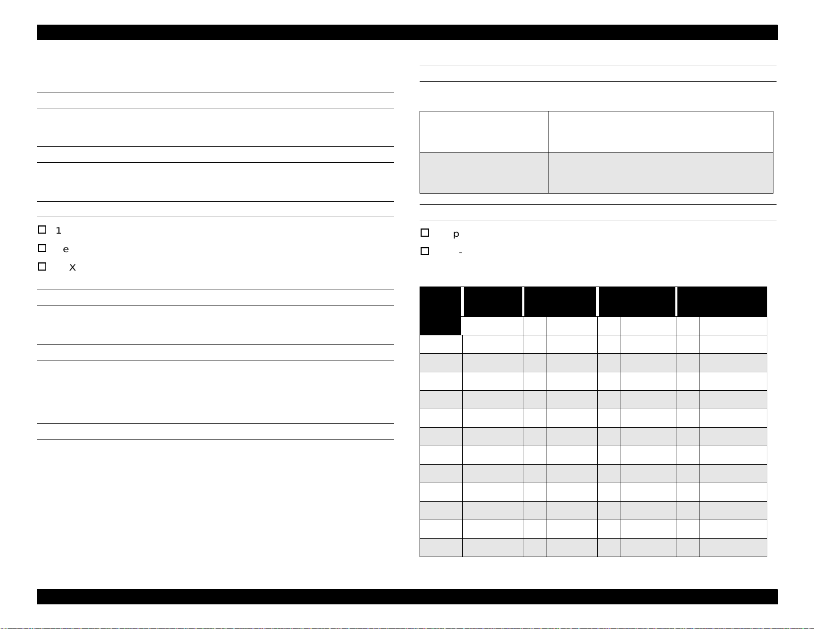
1.4.1.1 Switch Function
Table 1-7. Switch Function
Name Function
Special Shooting Mode with LCD monitor on.
Monitor Shooting Mode
VF Shooting Mode (LCD monitor off)
Dial Switch
(Rotary-type)
Shutter 2 strokes shutter button (half / full stroke)
Top Buttons
OFF (Power off)
Playback Mode
Option Mode
Set-up Mode
Image Quality Setting (//
Self-timer Setting (on / off)
Flash Mode Setting
AUTO / Red Eyes Flat / Compulsion / Prohibition /
Slow Synchronization)
/
H
)
Figure 1-2. Front and Rear View
Product Description Visual Guidance and Switch Function 26
Page 27
EPSON PhotoPC 850Z Revision A
Table 1-7. Switch Function
Name Function
Zoom Lever Optical Zoom Lever (W/T)
Rear-function Button
Diopter Switch VF (View Finder) Diopter collecting Switch
Operate by 7 buttons independ entl y
(Rear to 8. GUI explanation)
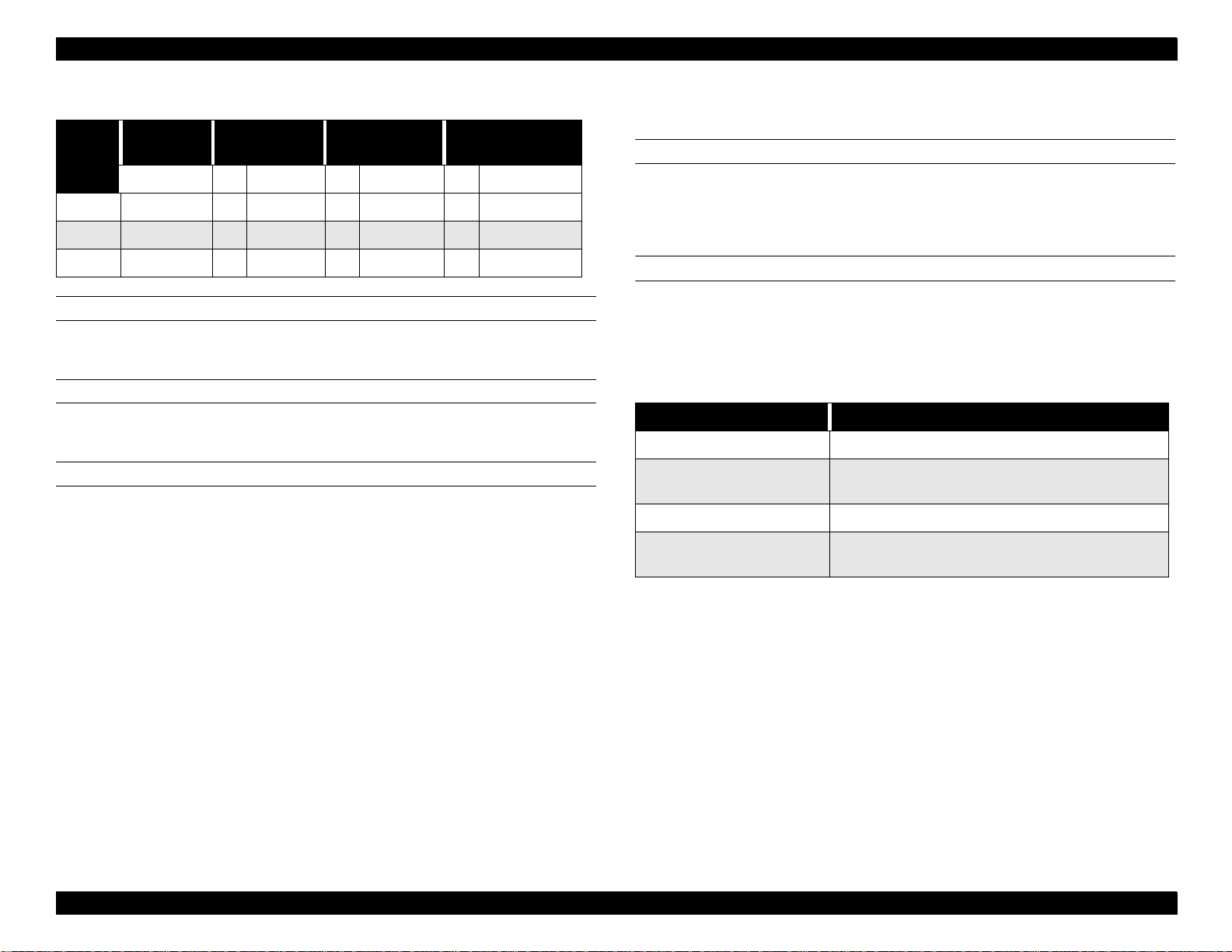
1.4.1.2 LED Condition
Table 1-8. LED
Camera
Condition
Green-LED
Ready to Shoot Turn on Turn on
Focusing Turn on
Focus Lock Turn on Turn on
Moving the taken
photo file to compact
flash memory card.
Full External Memory
Low Battery Warning
Error Turn on
Self-timer Start Turn on
Blink
(0.8 sec step)
Shooting
Condition
Red-LED
Blink
(0.8 sec step)
Blink
(1.0 sec step)
Shooting
Condition
Green-LED
Blink
(0.2 sec step)
Self-timer
Condition
Red-LED
Accelerating
blink
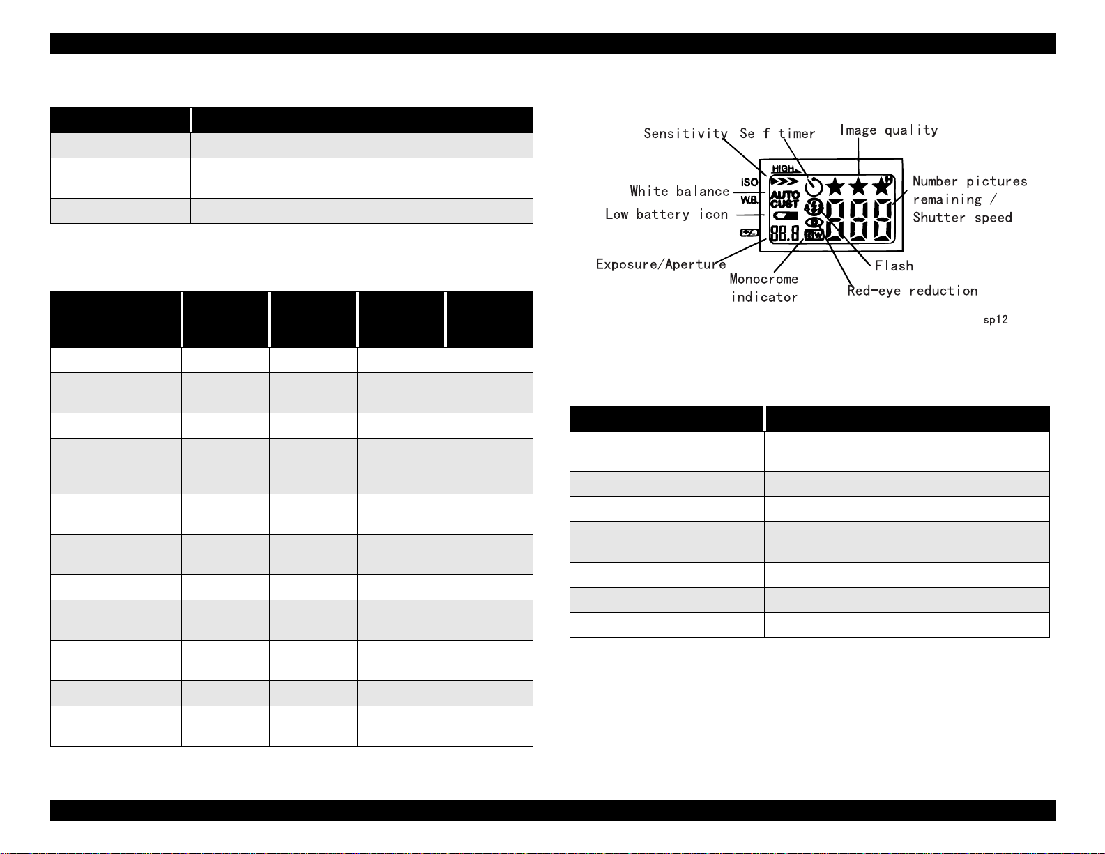
1.4.1.3 Control LCD
Figure 1-4. Control LCD Panel
Table 1-9. Control LCD Functions
Name Function
ISO Sensitivity Setting
White Balance Setting Indicates white balance setting.
Low-battery Warning Indicates when the battery is low.
Exposure Adjustment Value
Image Quality Setting Indicates image quality setting.
HyPict Indicates HyPict mode.
Monochrome Indicates on monochrome mode.
Indicates ISO sensitivity setting (Standard
ISO100 / Fine 200 / Super Fine 400).
Indicates exposure adjustment value
(when using half shutter).
Turn the switch on
(Only shooting mode)
Charging Flash Turn on Blink
Playback Mo de
Setup Mode
Turn on
Turn on
Blink
(0.2 sec step)
Product Description Visual Guidance and Switch Function 27
Page 28
EPSON PhotoPC 850Z Revision A
Table 1-9. Control LCD Functions
Name Function
Self Timer Indicates when self-timer is set.
Flash Indicates flash setting.
Available remaining pictures
Available remaining pictures in buffer in
Available Remaining Pictures
quick taking mode
Shutter speed by half-shutter
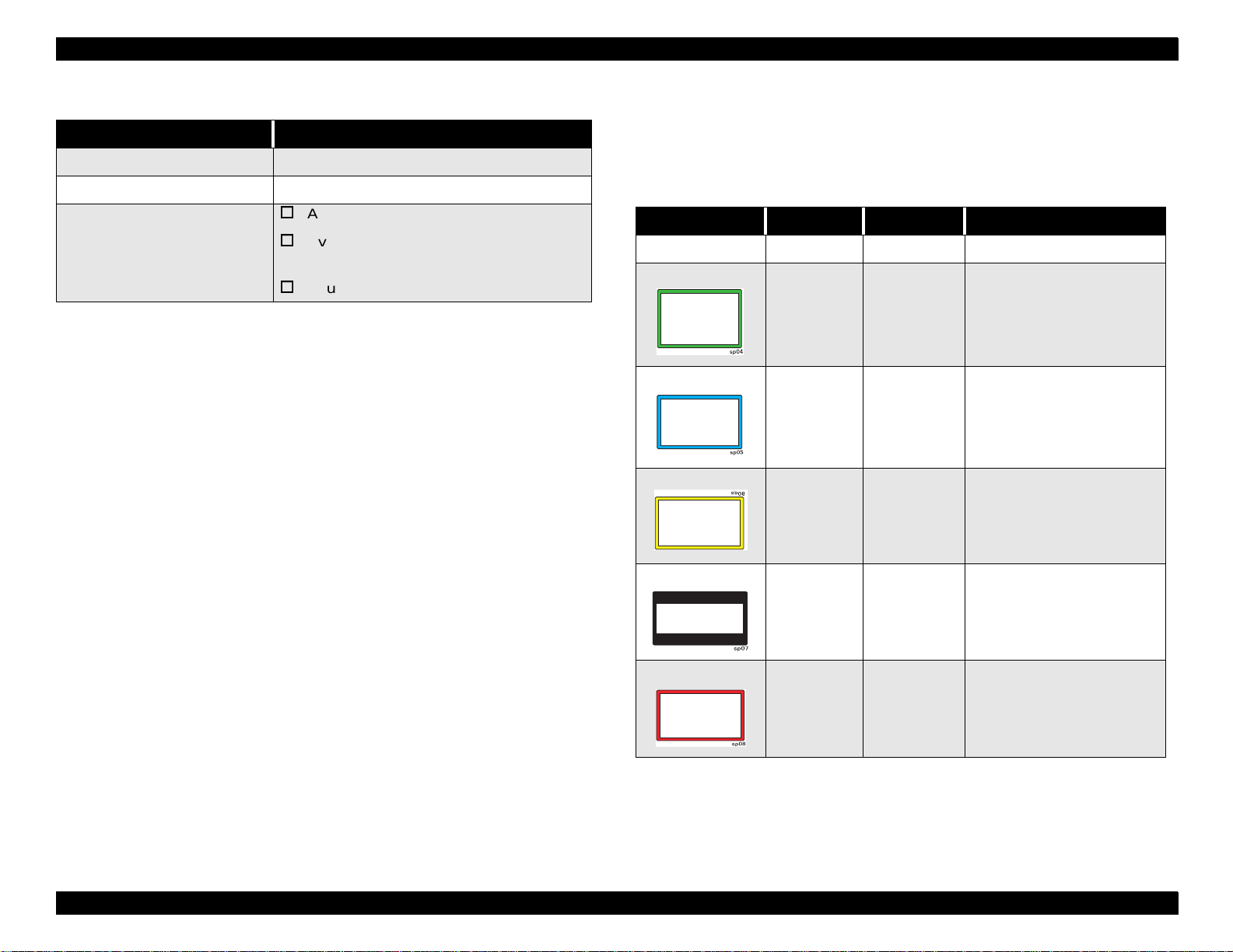
1.4.1.4 LCD Monitor
LCD monitor displays a different color frame for each function only when
shooting in LCD mode and continuous shooting mode are on.
Table 1-10. Color Frames
LCD Frame Color Mode Note
Nothing displayed - Preparing -
Green Macro Indicates “Macro” for seconds.
Blue
Yellow
MONOCHROMEIndicates “MONOCHROME”
for seconds.
x2 Digital
Zoom
Indicates “ZOOM” for
seconds.
NOTE:
Black margin
on the top
and bottom
Red
Priority of Color Frame:
Panorama
Continuous
Shooting
Indicates “Panorama” for
seconds.
indicates “Continuous
shooting” for seconds.
Continuous Shooting > Digital Zoom > Macro > Monochrome
(T.B.D)
Product Description Visual Guidance and Switch Function 28
Page 29
EPSON PhotoPC 850Z Revision A
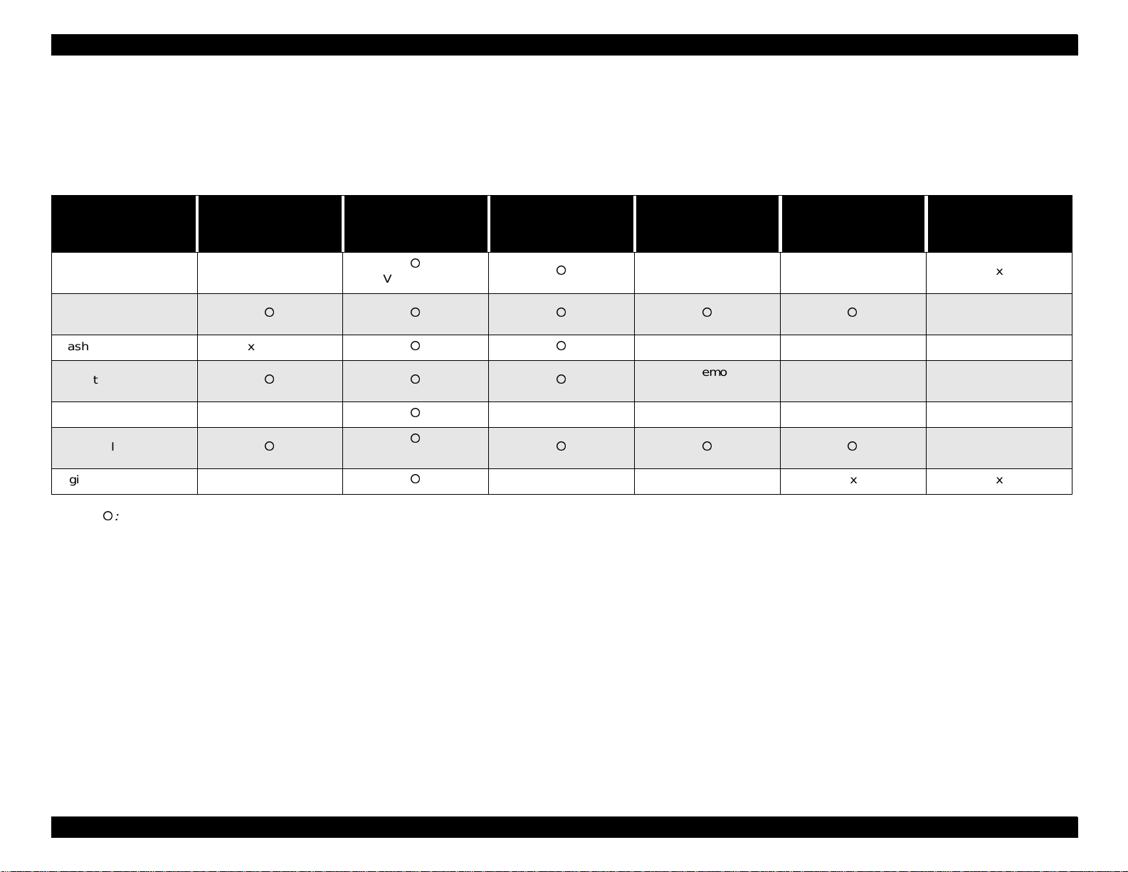
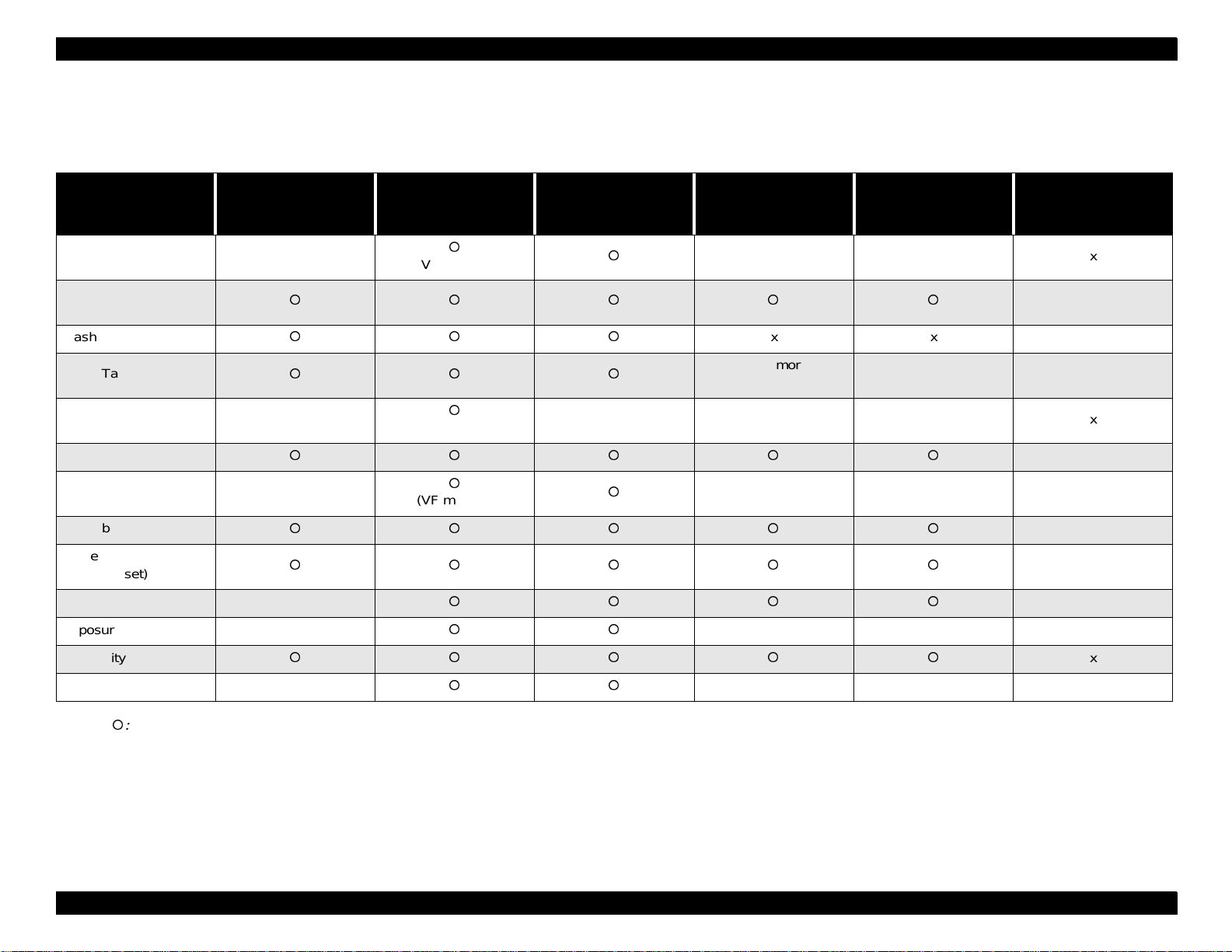
1.4.2 Setting Items
1.4.2.1 Full Auto Shooting Mode
The following items are sustained in VF mode and Monitor Shooting mode.
Table 1-11. Full Auto Shooting Mode (in VF mode and Monitor Shooting mode)
When Rotary Switch
point or pass OFF
Panorama / Macro x
Change image
resolution
Flash x (Auto)
Quick taking mode
Interval value x
Set up value
Digital zoom x
NOTE:
: Encode x: Disable
Rotary Switch
change-over between
shooting modes
(VF mode: x)
(VF mode:x)
Shut down by power
saving mode
xxxx
xxxx
Shut down by low
battery
xxx
xxx
Transfer memories in
buffer to the CF card
Replace battery
(Super Capa effective)
To the normal mode x
Replace battery
(Super Capa
ineffective)
x
x
Product Description Visual Guidance and Switch Function 29
Page 30
EPSON PhotoPC 850Z Revision A
1.4.2.2 Program Mode
The following items are sustained in VF mode and Monitor shooting mode.
Table 1-12. Program Mode (in VF mode and Monitor Shooting mode)
When Rotary Switch
point or pass OFF
Panorama / Macro x
Change image
resolution
Flash
Quick Taking mode
Interval value x
Set up value
Priority mode x
White balance
White balance
(Program set)
Metering system select x
Exposure Adjustment x
Rotary Switch
change-over between
shooting modes
(VF mode:x)
(VF mode:x)
(VF mode:x)
Shut down by power
saving mode
xxxx
Shut down by
low battery
xxx
xxx
Transfer memories in
buffer to the CF card
xxx
xxx
Replace battery
(Super Capa effective)
To the normal mode x
Replace battery
(Super Capa
ineffective)
x
x
x
x
x
Sensitivity
Digital zoom x
NOTE:
: Encode x: Disable
xxx
x
Product Description Visual Guidance and Switch Function 30
Page 31

EPSON PhotoPC 850Z Revision A
1.4.2.3 Manual Mode
The following items are sustained in VF mode and Monitor shooting mode.
Table 1-13. Manual Mode (in VF mode and Monitor Shooting mode)
When Rotary Switch
point or pass OFF
Panorama / Macro x
change image resolution
Flash
Quick taking mode
Interval value x
Set up value
Priority mode
Manual exposure shooting
mode
White balance
White balance
(Program set)
Metering system select
Rotary Switch
change-over
between shooting
modes
(VF mode:x)
(VF mode:x)
Shut down by power
saving mode
xxxx
Shut down by
low battery
xxx
xxx
Transfer memories in
buffer to the CF card
Replace battery
(Super Capa
effective)
To the normal mode x
Replace battery
(Super Capa
ineffective)
x
x
x
x
x
x
x
Exposure Adjustment
Sensitivity
MF Shooting set x
Shutter speed adjusted x
Digital zoom
NOTE:
: Encode x: Disable
x x x
xxx
x
x
x
Product Description Visual Guidance and Switch Function 31
Page 32

EPSON PhotoPC 850Z Revision A
1.5 Attach Products
1.5.1 Attach Cable
1.5.1.1 DOS/V Connector Cable
Length: 1.5m
Connector:
Camera side: 14-pin connector (female)
PC side: 9-pin D-SUB connector (female)
Camera
PC
1.5.1.2 Macintosh Connector Cable
Length: 1.5m
Connector:
Camera side: 14-pin connector (female)
PC or Printer Connector: 8-pin mini-DIN (male)
)
Camera
Printer / MAC
(exluding iMac)
Figure 1-6. Macintosh Connector Cable
Figure 1-5. DOS/V Connector Cable
Product Description Attach Products 32
Page 33

EPSON PhotoPC 850Z Revision A
1.5.1.3 USB Interf ace Cable
Length: 1.5m
Connector:
Camera side: 14-pin connector (female)
PC side: USB
Camera
USB(iMac)
1.5.1.4 Interface Cable for Video and Audio
Length: 1.5m
Connector:
Camera side: Mini pin
Video side: RCA (yellow)
Audio: RCA (white)
1.5.2 Other Attached Products
Camera case (T.B.D)
Strap
Shoulder belt
Lens accessories adapter
Figure 1-7. USB Interface Cable
Product Description Attach Products 33
Page 34

EPSON PhotoPC 850Z Revision A
1.6 Option
1.6.1 Standard Option
AC ADAPTER
Model Name: EU-40
Input Voltage: AC 100-240V, 50-60 Hz, 30VA (T.B.D)
Output Voltage: DC 7.0V, 2.0A
NI-MH BATTERY
Model Name: EU-24
Output Voltage: 1.2V / one battery
Capacity : 1500 mAH/battery
NI-MH BATTERY CHARGER
Model Name: EU-38
Input Voltage: AC 100-240V, 50-60 Hz 10 VA (T.B.D)
Output Voltage: DC 1.2V 490 mA x 4 (T.B.D)
Charging Time: 2.5H (T.B.D)
Product Description Option 34
Page 35

EPSON PhotoPC 850Z Revision A
1.7 Environmental Conditions
OPERATIONAL CONDITION AND KEEPING CONDITION
Temperature
Operating: 5-35
Keeping: -20-60
Humidity
Operating: 30-90% without condensation
Keeping: 10-90% without condensation
Shock-resistance
Keeping: 70G
POWER SUPPLY
DC input voltage (AC adapter)
Min.: DC 2.96V (T.B.D)
Max.: DC 3.85V (T.B.D)
ASSUMED SITUATION
Place
Home, Office, Outdoor
Water Resistance
Not supported
°C
°C
Product Description Environmental Conditions 35
Page 36

EPSON PhotoPC 850Z Revision A
1.8 Safety and Others
EMI AND SAFETY STANDARD
USA
FCC part 15 subpart B class B
Canada
CSA C108.8 class B
Europe
EMC Directive 89/ 336/ EEC
(CE-marking)
EN55022 Class B
EN61000-3-2 (using AC adapter)
EN61000-3-3 (using AC adapter)
EN50082-1
IEC801-2
IEC801-3
IEC801-4
Europe
EN 55022 (CISPR Pub.22)
Class B
Australia
AS/ NZS 3548 class B
Taiwan
EMI: CNS 13438-C6357
Japan
VCCI Class B
Korea
The rule of Electromagnetic wave in Korea
Product Description Safety and Others 36
Page 37

EPSON PhotoPC 850Z Revision A
1.9 Inhibitions and Cautions
Never see the sun through view finder
W ARNING
CAUTION
Keep young children away from the camera, especially
watch that the long strap does not cause choking
accidents.
Never use any AC adapters and batteries other than the
approved ones.
If the camera will not be in use for a long time, remove
batteries.
Be sure to insert batteries with correct polarity.
Product Description Inhibitions and Cautions 37
Page 38

OPERATING PRINCIPLES
Page 39

EPSON PhotoPC 850Z Revision A
Electric Circuit
2.1 Overview
Major component of PhotoPC 850Z consists of electric circuit and the Lens
Assy. The figure below shows layout of the major electric boards.
The electric circuit consists of CA1, CA2, SY1, SY2, ST1, TB1, TB2, and
PW1 Boards. The table below shows functions of each board.
Table 2-1. Board Function
Board Function
CCD image sensor interline type
• CCD clock drive
CA1
CA2
SY1
• A/D conversion of image data
• Drives the Lens Assy.
(shutter, aperture, focus, and zoom)
Consists of RISC-CPU, ASIC, 8Mbit Flash-ROM, 32Mbit
SDRAM.
• Digital clamp
•γ correction, color generation, matrix, horiz ontal and
vertical aperture
• SDRAM controller
• USB control
8 bit microprocessor
• Operatio n key input
• Controls LCD panel display
• Controls the power circuits
• Controls the flash charging
SY2 LED in the Viewfinder
ST1 Controls the external flash.
Figure 2-1. Major Component
Lens Assy.
Includes the Optical Zoom Mechanism, Shutter Mechanism, Aperture
Mechanism, and Focus Mechanism.
Lens Focus Distance: 6.5 - 19.5mm
Lens Construction: 8 elements in 6 groups
TB1 Battery circuit
TB2
PW1
Barrier switch board
• Monitors opening/closing of the barrier
Power Circuit
• Switch controller, short-circuit protection circuit
• Digital 5V and analog system power output
• Digital 3.25V system pow er output
• LCD system power supply
• Backlight power supply output
Operating Principles Overview 39
Page 40

EPSON PhotoPC 850Z Revision A
2.2 Operating Principles of Circuit Boards
The figure below shows the block diagram of all boards in PhotoPC 850Z.
64Mbit
Compact Flash
Compact Flash
Card
Card
Driver
Driver
LENS
74AC273
74AC273
8Mbit
8Mbit
Frash
Frash
Memory
Memory
1600~1200
RISC
RISC
CPU
CPU
10bitA/D
10bitA/D
@
AGC
CDS
@
AGC
CDS
1600~1200
IS-CCD
IS-CCD
Address2
SDRAM
SDRAM
Controller
Controller
SRAM
SRAM
Controller
Controller
SG/TG
SG/TG
CLK
CLK
GEN
GEN
64Mbit
SDRAM
SDRAM
Data2
Controller
Controller
Signal
Signal
Processor
Processor
USB
USB
JPEG
JPEG
AF/AE.AWB
AF/AE.AWB
Integrator
Integrator
Encoder
Encoder
YC
8bit
8bit
8bit
8bit
D/A
D/A
D/A
D/A
8bit
8bit
D/A
D/A
JPEG
JPEG
SYSTEM
ASIC
Data1
Address1
UART
UART
PIO
PIO
CA2_BLOCK
Driver
Driver
RS232C
CA1
BLOCK
AV JACK
DC JACK
Battery
~
4
1.5V
@
Electoronic
Electoronic
Flash
Flash
2
1
3
+
|
DC-DC
DC-DC
Converter
Converter
PW1_BLOCK
72MHz
48MHz
Y
Driver
Driver
Display
Display
2 inch
2 inch
C
kbc
kbc
kbc
kbc
Y-C
MIX
MIX
Y-C
Video
Video
Driver
Driver
Audio
Audio
AMP
AMP
SY1
BLOCK
SPEAKER
8bit
8bit
CPU
CPU
1MHz
CLK
@
32.768Hz
CLK
Figure 2-2. Block Diagram
Operating Principles Operating Principles of Circuit Boards 40
Page 41

EPSON PhotoPC 850Z Revision A
Pin 1
2
10
48
4
H
V
Pin 11
2.2.1 CA1 Circuit Description
CA1 Board consists of the f ollowing ICs.
IC Configuration
IC903 (ICX224AK): CCD Imager
IC902 (74ACTO4MTC): H Driver
IC904 (CXD3400N): V Driver
The figure below shows the block diagram of the CA1 Board.
2.2.1.1 IC903 (CCD)
Specification of the CCD is shown below.
Structure
Interline Type CCD Image Sensor
Optical Size: 1/2 inch format
Effective Pixels: 636 (H) x 1236 (V)
Total Pixels: 688 (H) x 1248 (V)
Optical Black Sensing:
Horizontal (H) Direction: Front 4 pixels, Rear 48 pixels
Vertical (V) Direction: Front 10 pixels, Rear 2 pixels
Figure 2-4. Optical Black Layout
Number of Dummy Bit:
Horizontal: 28
Vertial: 1
Figure 2-3. CA1 Circuit Block Diagram
Operating Principles Operating Principles of Circuit Boards 41
Page 42

EPSON PhotoPC 850Z Revision A
4
3B
2
1A
1B
D
3A
D
T
CCD block diagram and terminals are shown below. For your reference, Ye is
the Yellow detection cell, Mg is the Magenta detection cell, CY is the Cyan
detection cell, and G is the Green detection cell.
10
11
VOU
VDD
9
12
GN
RG
8
13
NC
H 2
V
GN
7
6
Ye
G
Ye
G
Ye
Vertical register
G
Horizontal register
15
14
GND
H 1
5
16
V
Cy
Mg
Cy
Mg
Cy
Mg
SUB
4
17
V
Ye
Ye
Ye
SUB
C
V
3
2
Cy
G
Mg
Cy
G
Mg
Cy
G
Mg
18
19
VL
V
H 1
V
1
(Note)
20
2
H
Table 2-2. CCD Pin Description
Pin No. Symbol Pin Description Waveform Voltage
1V
2, 3
4V
5, 6
7, 9 GND GND GND 0V
10 VOUT Signal Output Approx. 10V
11 VDD Circuit Power DC 15V
Vφ3A,
Vφ3B
Vφ1A,
Vφ1B
Vertical Register
4
φ
Vertical Register
Vertical Register
2
φ
Vertical Register
Transfer Clock
Transfer Clock
Transfer Clock
Transfer Clock
-7.5V, 0V
-7.5V, 0V,
15V
-7.5V, 0V
-7.5V, 0V,
15V
(Note) :
Photo sensor
12
φ
RG
Reset Gate
Clock
12.5V, 17.5V
Figure 2-5. CCD Block Diagram
Horizontal
13, 20 Hφ2
14, 19 Hφ1
Register Transfer
Clock
Horizontal
Register Transfer
Clock
0V, 5V
0V, 5V
Operating Principles Operating Principles of Circuit Boards 42
Page 43

EPSON PhotoPC 850Z Revision A
1A
1
1Y
2
2A
3
2Y
4
3A
5
3Y
6
GND
7
4Y
8
4A
9
5Y
10
5A
11
6Y
12
6A
13
V
CC
14
Table 2-2. CCD Pin Description (Continued)
Pin No. Symbol Pin Description Waveform Voltage
16
17 CSUB Substrate Bias DC
18 VL
NOTE:
SUB Substrate Clock DC Approx. 8V
φ
Protection
Transistor Bias
DC
----: When the sensor reads-out.
Approx. 8V
(Different
from every
CCD)
2.2.1.2 IC902 (H Driver) and IC904 (V Driver)
H Driver (IC902) and V Driver (IC904) are necessary to generate the clocks
(vertical transfer clock, horizontal transfer clock, and electronic shutter clock)
which drive the CCD.
IC902 is an inverter IC which drives the horizontal CCDs (H1 and H2). In
addition, the XV1-XV4 signals which are output from IC102 are the vertical
transfer clocks, and the XSG1 and XSG signals output from IC102 are
superimposed onto XV1 and XV3 at IC904 in order to generate a ternary pulse.
Furthermore, the XSUB signal which is output from IC102 is used as the sweep
pulse for the electronic shutter, and the RG signal which is output from IC102 is
the reset gate clock.
Figure 2-6. IC902 Block Diagram
Operating Principles Operating Principles of Circuit Boards 43
Page 44

EPSON PhotoPC 850Z Revision A
8
4
5
6
7
0
9
1
2
3
2.2.1.3 Lens Drive Block
DD
1
2
3
4
5
6
7
8
9
10
V
XSHT
XV3
XSG3B
XSG3A
XV1
XSG1B
XSG1A
XV4
XV2
Input
Buffer
SHT
V3B
V
V3A
V1B
V
V1A
V4
V2
GND
2
1
L
1
1
1
H
1
1
1
1
1
Shutter Drive
The shutter drive signal (PCTRL) which is output from the ASIC expansion
port (IC108) is moved regular current drive for shutter, and the shutter
plunger is opened and closed.
The iris stepping motor drive signals (ACTRL1, ACTRL2, ACTRL3,
ACTRL4) which are output from the ASIC expansion port (IC108) are
driven by the motor driver (IC957), and the iris is moved six times.
Detection of the standard iris positions is carried out by means of the
photointerrupter (P12) inside the lens block.
Focus Drive
The focus stepping motor drive signals (LDIN1, LDIN2, LDIN3, LDIN4)
which are output from the ASIC expansion port (IC107) are driven by the
motor driver (IC954). Detection of the standard focusing positions is carried
out by means of the photo interrupter (PI) inside the lens block.
Zoom Drive
The zoom stepping motor drive signals (ZIN1, ZIN2, ZIN3, ZIN4) which are
output from the ASIC expansion port (IC107) are driven by the motor driver
(IC953). Detection of the standard zooming positions is carried out by
means of the photoreflectors (PR1, PR2 ) insid e the lens block.
Figure 2-7. IC904 Block Diagram
Operating Principles Operating Principles of Circuit Boards 44
Page 45

EPSON PhotoPC 850Z Revision A
2.2.2 CA2 Circuit Description
2.2.2.1 Circuit Description
DIGITAL CLAMP
The optical black section of the CCD extracts the average values from the
subsequent data to make the black level of the CCD output data uniform for
each line.
@
The optical black section of the CCD averaged value for each line is taken as
the sum of the value for the previous line multiplied by the coefficient k and the
value for the current line multiplied by the coefficient 1-k.
@
@
@
@
@
@
Figure 2-8. CA2 Circuit Block Diagram
Operating Principles Operating Principles of Circuit Boards 45
Page 46

EPSON PhotoPC 850Z Revision A
SIGNAL PROCESSOR
Correction Circuit
γ
This circuit performs (gamma) correction in order to maintain a linear
relationship between the light input to the camera and the light output from
the picture screen.
Color Generation Circuit
This circuit converts the CCD data into RGB signals.
Matrix Circuit
This circuit generates Y signals, R-Y signals and B-Y signals from the RGB
signals.
Horizontal and Vertical Aperture Circuit
This circuit is used to generate the aperture signal.
AE/AWB AND AF COMPUTING CIRCUIT
The AE/AWB carries out computations based on a 64-segment screen, and the
AF carries out computations based on a 6-segment screen.
SDRAM CONTROLLER
This circuit outputs address, RAS, CAS, and AS data for controlling the
SDRAM. It also refreshes the SDRAM.
TG/SG
Timing generated for 2 million pixel CCD control.
DIGITAL ENCODER
It generates chroma signal from color difference signal.
COMMUNICATION CONTROL
USART
The RS-232C can be sued for both synchronous and asynchronous
transmission.
SIO
This is the interface for the 4-bit microprocessor.
PIO/PWM/SIO for LCD
8-bit parallel input and output makes it possible to switch between
individual input/output and PW M inpu t/ou tput .
Operating Principles Operating Principles of Circuit Boards 46
Page 47

EPSON PhotoPC 850Z Revision A
2.2.2.2 Operation Outline
When the shutter opens, the reset signals (ASIC and CPU) and the serial
signals (“Take a picture” commands) from the 4-bit microprocessor are input
and operation starts. When the TG/SG drives the CCD, picture data passes
through the A/D and CDS, and is then input to the ASIC as 10-bit data. The AF,
AE, AWB, shutter, and AGC value are computed from this data, and three
exposures are made to obtain the optimum picture.
The data which has already been stored in the SDRAM is read by the CPU and
color generation is carried out. Each pixel is interpolated from the surrounding
data as being either Ye, Cy, Mg, or B primary color data to produce R, G, and B
data. At this time, correction of the lens distortion which is a characteristic of
wide-angle lenses is carried out. After AWB and γ processing are carried out, a
matrix is generated and aperture correction is carried out for the Y signal, and
the data is then compressed by JPEG and is then written to card memory
(smart media).
When data is to be output to an external device, the data is taken from the
memory and output via the USART. When played back on the LCD and
monitor, data is transferred from memory to the SDRAM, and the image is then
elongated so that it is displayed over the SDRAM display area.
2.2.2.3 LCD Block
While monitoring, YUV conversion is carried out for the 10-bit CCD data which
is input from the A/D conversion block to the ASIC and is then transferred to
the DRAM so that the CCD data can be displayed on the LCD.
The data which has accumulated in the DRAM is passed through the NTSC
encoder, and after D/A conversion is carried out to change the data into a Y/C
signal, the data is sent to the LCD panel and displayed.
If the shutter button is pressed in this condition, the 10-bit data which is output
from the A/D conversion block of the CCD is sent to the DRAM (DMA transfer),
and after processor, it is displayed on the LCD as a freeze-frame image.
During playback, the JPEG image data which has accumulated in the flash
memory is converted to YUV signals, and then in the same way as during the
monitoring, it is passed through the NTSC encoder, and after D/A conversion is
carried out to change the data into a Y/C signal, the data is sent to the LCD
panel and displayed.
The two analog signal (Y/C signals) from the ASIC are converted into RGB
signals by the LCD driver, and these RGB signals and the control signal which
is output by the LCD driver are used to drive the LCD panel. The RGB signals
are 1H transposed so that no DC component is present in the LCD element,
and the two horizontal shift register clocks drive the horizontal shift registers
inside the LCD panel so that the 1H transposed RGB signals are applied to the
LCD panel. Since the LCD closes more as the difference in potential between
the COM (common polar voltage: fixed at DC) and the R, G, and B signals
becomes greater the display becomes darker; if the difference in potential is
smaller, the element opens and the LCD becomes brighter.
Operating Principles Operating Principles of Circuit Boards 47
Page 48

EPSON PhotoPC 850Z Revision A
2.2.3 PW1 Power Circuit Description
2.2.3.1 Outline
This is the main power circuit comprising of the following blocks:
Switching controller (IC501)
Digital 5V and analog system power output (T5001, Q5001)
Digital 3.25V system power supply (Q5007)
LCD system power supply (Q5008, T5002)
Backlight power supply output (Q5011, T5003)
Figure 2-9. PW Power Circuit Block Diagram
Operating Principles Operating Principles of Circuit Boards 48
Page 49

EPSON PhotoPC 850Z Revision A
2.2.3.2 Switching Controller (IC501)
This is the basic circuit which is necessary for controlling the power supply for a
PWM-type switching regulator, and it is provided with four built-in channels.
Only CH1 (digital 5V, analog system), CH3 (LCD system), CH2 (digital 3.25V),
and CH4 (backlight) are used. Feedback from 5.1V (D) (CH1), 3.0V (D) (CH2),
5.3V (L) (CH3), and 6.3-8.9V (L) (CH4) power supply outputs is received, and
the PWM duty is varied so that each one is maintained at the correct voltage
setting level.
2.2.3.3 Shot-Circuit Protection Circuit
If output is short-circulated for the length of time determined by the condenser
which is connected to Pin (17) of IC501, all output is turned off. The control
signal (P ON, P(A) ON, and LCD ON) are re-controlled to restore output.
2.2.3.4 Digital 5V and Analog System Power Output
5.1V (D), 15.2V (A), -7.7V (A), and 5.1V (A) are output. Feedback for the 5.1V
(D) is provided to the switching controller (Pins (29) of IC501) so that PWM
control can be carried out.
2.2.3.5 Digital 3.25V System Power Output
3.25V (D) is output. Feedback is provided to the switching controller (Pin (26)
of IC501) so that PWM control can be carried out.
2.2.3.6 LCD System Power Output
5.3V (L), 12.4V (L), and 15V (L) are output. Feedback for the 5.3V (L) is
provided to the switching controller (Pin (11) of IC501) so that PWM control can
be carri ed out.
2.2.3.7 Backlight Power Supply Output
The power which is input to the inverter transformer (T5003) is controlled by
means of Q5011, and 7.7V or 8.9V is output depending on the luminance
mode of the LCD panel.
Operating Principles Operating Principles of Circuit Boards 49
Page 50

EPSON PhotoPC 850Z Revision A
2.2.4 PW1 Strobe Circuit Description
2.2.4.1 Charging Circuit
When UNREG power is supplied to the charge circuit and the CHG signal
becomes High (3.3V), the charging circuit starts operating and the main
electrolytic capacitor is charged with high-voltage direct current.
However, when the CHG signal is Low (0V), the charging circuit does not
operate.
Figure 2-10. PW1 Strobe Circuit Block Diagram
Operating Principles Operating Principles of Circuit Boards 50
Page 51

EPSON PhotoPC 850Z Revision A
W ARNING
POWER SWITCH
When the CHG signal switches to High, Q5406 turns ON and the charging
circuit starts operating.
POWER SUPPLY FILTER
L5401 and C5401 constitute the power supply filter. They smooth out ripples in
the current which accompany the switching of the oscillation transformer.
OSCILLATION CIRCUIT
This circuit generates an AC voltage (pulse) in order to increase the UNREG
power supply voltage when drops in current occur. This circuit generates a
drive pulse with a frequency of approximately 50-100 kHz. Since self-excited
light omission is used, the oscillation frequency changes according to the drive
conditions.
RECTIFIER CIRCUIT
The high-voltage alternating current which is generated at the secondary side
of T5401 is rectified to produce a high-voltage direct current and is
accumulated at electrolytic capacitor C5412 on the main circuit board.
VOLTAGE MONITORING CIRCUIT
This circuit is used to maintain the voltage accumulated at C5412 at a
constance level. After the charging voltage is divided and converted to a lower
voltage by R5417 and R5419, it is output to the SY1 circuit board as the
monitoring voltage VMONIT. When this VMONIT voltage reaches a specified
level at the SY1 circuit board, the CHG signal is switched to Low and charging
is interrupted.
2.2.4.2 Light Emission Circuit
When RDY and TRIG signals are input from the ASIC expansion port, the
stroboscope emits light.
EMISSION CONTROL CIRCUIT
When the RDY signal is input to the emission control ci r cuit, Q5 409 swi tches
on and preparation is made to let current flow to the light emitting element.
When a STOP signal is input, the stroboscope stops emitting light.
TRIGGER CIRCUIT
When a TRIG signal is input to the trigger circuit, D5405 switches on, a highvoltage pulse of several kilovolts is generated inside the trigger circuit, and this
pulse is applied to the light emitting part.
LIGHT EMITTING ELEMENT
When the high-voltage pulse from the trigger circuit is applied to the light
emitting part, current flows to the light emitting element and light is emitted.
There is a danger of getting electric shock from the PW1
board because of C5412. When handling this board, make
sure to hold the edges of the board and never touch the
board surface. For your safety, discharge the charged
energy of C5412 before handling the board. (See Chapter 4
“Disassembly and Assembly” for more details.)
Operating Principles Operating Principles of Circuit Boards 51
Page 52

EPSON PhotoPC 850Z Revision A
2.2.5 SY1 Circuit Description
2.2.5.1 Configuration and Functions
Refer to the block diagram for the overall configuration of the SY1 circuit board.
The configuration of the SY1 circuit board centers around a 8-bit
microprocessor (IC301).
The 8-bit microprocessor handles the following functions:
Operation key input
Mode LCD display
Clock control
Power ON/OFF
Strobe charge control
Figure 2-11. SY1/SY2 Circuit Block Diagram
Operating Principles Operating Principles of Circuit Boards 52
Page 53

EPSON PhotoPC 850Z Revision A
Table 2-3. 8-bit Microprocessor Port Specification
Pin Signal Name I/O Outline
1 CHG VOL I Strobe charge c oltage input (analog in put)
2, 3 NOT USED - Connected to GND
4-7 SCAN IN 0-3 I Key matrix input
8 AVDD - Analog power input terminal
9 AVREF I Analog standard voltage input terminal
10 /STBY (R) LED O Standby LED (Red) drive, L: LED light
11 /STBY (G) LED O Standby LED (Green) drive, L: LED light
12 VSS - GND
13 /SELF LED O Self-timer LED drive, L: LED light
14 /STATUS LED O Viewfinder LED drive, L: LED light
15-19 NOT USED - Connected to GND
20 /AVREF ON O Analog standard voltage ON/OFF signal, L: ON
21 NOT USED - 22 CHG ON O Strobe charge ON/OFF signal
23-25 COM1-COM3 O Mode LCD common output
26 NOT USED - 27 BIAS - Mode LCD drive power supply (VLCO)
28-30 VLC0-VLC2 - Mode LCD power input terminal
31 VSS - GND
32-51 S1-S20 O LCD segment output 1-20
52-55 NOT USED - -
56 Ver. DET O Pull up
57-59 /SCAN IN 4-6 I Key matrix input
64 WAKE UP O SPARC Wake up terminal
Table 2-3. 8-bit Microprocessor Port Specification (Continued)
Pin Signal Name I/O Outline
65 BARRIER M - O Barrier motor drive signal, H: ON
66 BARRIER M + O Barrier motor drive signal, H: ON
67 BARRIER SW O Barrier motor regulator control signal, H: ON
68 NTZ PAL O NTSC/PAL system switch signal, H: ON
69 NOT USED - 70 PA ON O DC/DC converter (analog) On/Off signal, H: ON
71 P ON O DC/DC converter (digital) On/Off signal, H:ON
72 /DIN CONNECT I PC cable connection detectio n, H: Connection
73 /CARD I Memory card detection, L: Attachment
74 /AV JACK I Video cable connec tio n de tec t io n, L: C on nec ti on
75 SI I Serial data input (←ASIC)
76 SO O Serial data input (→ASIC)
77 SCK O Serial clock output (→ASIC)
78 IC - Internal connection (to VSS terminal directly)
79 XOUT O Main clock oscill ati on term ina l
80 XI N I Main clock oscillation terminal (4MHz)
81 VDD - VDD
82 XCIN I Clock oscillation terminal (32.768kHz)
83 XCOUT O Clock oscillation terminal
84 /RESET I Reset input
85 /BAT OFF I Battery OFF detection signal
86 RXD I Host wake up input terminal, L: ON
87 /SREQ I Serial communication request sig., L: Serial Req.
88 USB I USB cable connection detection, L : C on nec ti on
89 BARRIER SW0 I Barrier position detection signal
Operating Principles Operating Principles of Circuit Boards 53
Page 54

EPSON PhotoPC 850Z Revision A
Table 2-3. 8-bit Microprocessor Port Specification (Continued)
Pin Signal Name I/O Outline
90 BARRIER SW1 I Barrier position detection signal
91-94 SCAN OUT 0-3 O Key ma trix output
95 LCD ON O DC/DC converter (LCD system) On/Off sig., H:On
96 /ASIC TEST O ASIC control signal
97 /ASIC RESET O ASIC reset signal
98 /MAIN RESET O SPARC reset signal, L: Reset Output
99 AVSS - Analog GND input te rminal
100 BATTERY I Battery voltage input (analog input)
2.2.5.2 Internal Communi cation Bus
The SY1 circuit board carries out overall control of camera operation by
detecting the input from the keyboard and the condition of the camera circuits.
The 8-bit microprocessor reads the signals from each sensor element as input
data and outputs this data to the camera circuits (ASIC) or to the LCD display
device as operation mode setting data. The figure below shows the internal
communication between the 8-bit microprocessor, ASIC, and SPARC lite
circuits.
8-bit
Microprocessor
Figure 2-12. Internal Bus Communication System
Operating Principles Operating Principles of Circuit Boards 54
Page 55

EPSON PhotoPC 850Z Revision A
2.2.5.3 Key Operation
For details of the key operation, refer to the instruction manual.
Table 2-4. Key Operation
SCAN
OUT
0123456
0-ISO C + - 1 4 Menu WB 1 Test - -
Shutter
2
3 Set Up LCD CAM OFF PLAY
1st
* Self Strobe Zoom W
SCAN IN
Shutter
2nd
Sequent
IAL Shot
Zoom T
D. Print
2.2.5.4 Power Supply Control
The 8-bit microprocessor controls the power supply for the overall system. The
following is a description of how the power supply is turned on and off.
When the battery is attached, a regulated 3.2V voltage is normally input to the
8-bit microprocessor (IC301) by IC302 to carry out clock counting and power
switch checking even when the power switch is turned off, so that the camera
can start up again. When the battery is removed, the 8-bit microprocessor
operates in sleep mode using the backup super capacitor. At this time, the 8-bit
microprocessor only carries out clock counting, and waits in standby for the
battery to be attached again. When a switch is operated, the 4-bit
microprocessor supplies power to the system as required.
The 8-bit microprocessor first sets both the P (A) ON signal at pin (71) and the
P (A) ON signal at pin (70) to High, and then turns on the DC/DC converter.
After this, High signals are output from pins (97) and (88) so that the ASIC and
the SPARC lite are set to the active condition. If the LCD monitor is on, the pin
(95) is set to LCD ON signal, and the DC/DC converter for the LCD monitor is
turned on. Once SPARC lite processing is completed, the ASIC and the
SPARC lite return to the reset condition, all DC/DC converters are turned off,
and the power supply to the whole system is halted.
Table 2-5. Power Supply Control
Sparc
Supply Voltage 3.3V 3.3V 3.4V 5.0V
Lite
ASIC Memory
Drive/
Receiver
CCD
5V(A)
+15V
-7V
8bit
CPU
3.2V
(Always)
Mode
LCD
3.2V
(Always)
LCD
Monitor
5V(L)
+12V
etc.
OFF OFF OFF OFF OFF OFF 32KHz OFF OFF
Operating Principles Operating Principles of Circuit Boards 55
Page 56

EPSON PhotoPC 850Z Revision A
Table 2-5. Power Supply Control (Continued)
Sparc
Power
Switch ON
- Auto
Power
Down
C
Shutter
A
Switch ON
M
Resolution,
Flash, Self
Timer
Switch ON
LCD Special ON ON ON ON ON 4MHz ON ON
Play ON ON ON ON OFF 4MHz ON ON
Direct Print ON ON ON ON OFF 4MHz ON OFF
Set Up ON ON ON ON OFF 4MHz ON ON
ASIC Memory
Lite
OFF OFF OFF OFF OFF 4MHz ON OFF
ON ON ON ON
OFF OFF OFF OFF OFF 4MHz ON OFF
Drive/
Receiver
CCD
ON
→
OFF
8bit
CPU
4MHz ON OFF
Mode
LCD
LCD
Monitor
Operating Principles Operating Principles of Circuit Boards 56
Page 57

TROUBLESHOOTING
Page 58

EPSON PhotoPC 850Z Revision A
CAUTION
3.1 Overview
3.1.1 Error Indications
PhotoPC 850Z has a function to indicate an error with LED as shown in the
table below, but it does not indicate the detailed cause of the error.
Table 3-1. Error Indications
Camera
Condition
(Green)
Battery Out
Error On
Several different malfunctions can be found from the same symptom.
Therefore, follow the check points in the order shown in this chapter, and
perform proper repair service.
Before disassembling the camera, make sure that
W ARNING
batteries are removed or the AC adapter is disconnected
from the plug.
Electrolytic capacitor (C5412) mounted on the PW1 Board
is for flash emission. This capacitor is charged
automatically every time the power is turned on. Since
there is a possibility of getting electric shock during the
service operation, discharge the electricity by using the
cement resistance if you need to touch the capacitor for
repair service (see Chapter 4 "Disassembly and
Assembly" for details).
Shooting
Condition
(Red)
Blinks with an
interval of 0.1 sec.
Shooting
Condition
(Green)
Self-Timer
Condition
(Red)
3.2 Trouble Shooting
This section shows the procedure for checking malfunctioning unit or parts by
each abnormal symptom.
3.2.1 Camera Has No Power
Nothing is indicated on the LCD or red LED keeps blinking, and the camera
does not go into the stand-by state even if the dial switch is turned on after
installing batteries or connecting the AC adapter. In this case, refer to
Table 3-2 ~ 3-4.
If the 8-bit micro processor, which controls User I/F,
located on the SY1 Board has a problem, the signal
necessary to generate the various digital and analog
power source will not be generated. As a result, the
camera goes into "No Power" state.
Also, since this 8-bit micro processor performs serial
communication with the main CPU on the CA2 Board, if
trouble occurs on the CA2 Board, the same symptom as
above will appear.
Table 3-2. Check points when the camera has no power
Checking
Order
1
2
Check 91-pin (SCAN IN 0)
pulse input of IC301.
Check 7-pin (UNREG) pulse
input of IC302.
Check Point Judgement Solution
Check CN301, R3021,
NO
LOW Check PW1 and CA2.
and the harness
including the power
switch.
3
4
5
Check 81-pin (VDD) pulse
input of IC301.
Check 84-pin (/RESET) pulse
input of IC301.
Check 80-pin (/BAT OFF)
pulse input of IC301.
LOW Check IC302.
LOW Check IC302 and R3051.
LOW Check R3052.
Troubleshooting Overview 58
Page 59

EPSON PhotoPC 850Z Revision A
Table 3-2. Check points when the camera has no power
Checking
Order
6
7
8 Check IC301. -- --
Check 80-pin (XIN) osc illation
of IC301.
Check 82-pin (XCIN)
oscillation of IC301.
Check Point Judgement Solution
NO Check X3001.
NO
Check X3002, R3004,
C3001, and C3002.
3.2.2 No Shooting
Table 3-3. No Shooting
Checking
Order
1 Press the shutter button. -- --
2
3
Check 7-pin (SCAN IN 3)
pulse input of IC301.
Check 7-pin or 8-pin (/PON,
/P(A) ON) pulse input of
CN301.
Check Point Judgement Solution
Check POWER
NO
LOW
SWITCH, CN301,
Q3005, Q3006, R3024.
Check IC301, Q3005,
Q3006, and PW1.
3.2.3 Image Cannot be Taken
Table 3-4. Image Cannot be Taken
Checking
Order
Is the system drive clock
1
2
3 Check 61-pin (ZAS) of IC101. NG
4
5
6
7
(72MHz) input to 280-pin
(CLK IN1) of IC102?
Is CLK (36MHz) input to 132pin (CLK IN) of IC101?
Check 52-pin (ZBREQ) of
IC101.
Check 56-pin (ZBGRNT) of
IC101.
Check the signal of 118-pin
and 119-pin (IRL1, 2) of
IC101.
Check CPU and soldering for
the memory, etc.
Check Point Judgeme nt Solution
YES Check X1101 and IC111.
NO Check 278-pin of IC102.
Check the address with
IC121 and data bus.
NG Check ASIC
NG Check ASIC.
8-bit microprocessor and
NG
-- --
HAND SHAKE of RS232C are defective.
4
5
6 Check CA2. -- --
Is 6-pin, 12-pin, or 13-pin of
CN301 HIGH?
Is the serial communication
normal?
NO
NG Check IC301 and CA2.
Check IC301, PW1, and
CA2.
Troubleshooting Trouble Shooting 59
Page 60

DISASSEMBLY AND ASSEMBLY
Page 61

EPSON PhotoPC 850Z Revision A
4.1 Overview
This section describes disassembly and assembly procedures for the major
components of PhotoPC 850Z. Since assembly of this camera is relatively
complicated, procedures for disassembly and assembly are explained
individually.
4.1.1 Precautions
See the precautions below before disassembling and assembling the camera.
Disconnect the AC adaptor or remove batteries before
W ARNING
CAUTION
disassembling the camera.
Discharge electricity in the electrolytic capacitor by using
the cement resistance if you need to touch the PW1 Board
for repair service. The electrolytic capacitor (C5412)
mounted on the PW1 Board is for light emission, and is
designed to be charged automatically every time the
camera is turned on, and therefore there is a danger of
getting electric shock (see 4.2.1.1 “Discharging Electricity
from Capacitor”).
There are two repair levels for this product: first and
second maintenance.
Performance of the second maintenance is allowed only
by the service center which is equipped with special
instrument for adjustment. We do not guarantee repair
results by the others.
Refer to Table 4-1 for distinction between the first and
second maintenance.
Use the exclusive package material when transporting the
camera.
Table 4-1. Criterion for First and Second Maintenance
No. Replaced Part Required Adjustment Maintenance
1. Initialization
2. AWB adjustment
1 CA1 Board
2 CA2 Board
3 Lens
3. Color matrix adjustment
4. CCD defect detection adjustment
5. Lens adjustment
1. Initialization
2. AWB adjustment
3. Color matrix adjustment
4. CCD defect detection adjustment
5. Lens adjustment
6. LCD panel adjustment
Note: Always follow the order
described above except the lens
adjustment.
1. Initialization
2. AWB adjustment
3. Color matrix adjustment
4. CCD defect detection adjustment
5. Lens adjustment
Note: Always follow the order
described above except the lens
adjustment.
2nd Maintenance
2nd Maintenance
2nd Maintenance
Disassembly and Assembly Overview 61
Page 62

EPSON PhotoPC 850Z Revision A
Table 4-1. Criterion for First and Second Maintenance
No. Replaced Part Required Adjustment Maintenance
4 CCD Ditto 2nd Maintenance
5 LCD Monitor LCD panel adjustment 1st Maintenance
Note:
Perform the following adjustment if
you replaced the elements on the
SY1 Board (2nd maintenance).
Make sure to follow the adjustment
order except the lens adjustment.
1. IC501 Oscillation frequency
adjustment
2. 5.1V (D) voltage adjustment
6 PW1 Board
3. 3.25V (D) A voltage adjustment
4. 12.4V (L) voltage adjustment
5. 7.7V (L) voltage adjustment
6. Initialization
7. AWB adjustment
8. Color matrix adjustment
9. CCD defect detection adjustment
10.Lens adjustment
11.LCD panel adjustment
1st Maintenance
4.1.2 Equipment and Tools
The tables below show the recommended tools for repair service.
Table 4-2. Equipment
Name Note
Oscilloscope Higher than 100MHz
Digital Voltmeter --
Windows 95 or 98, and must have the following:
• CD-ROM drive
• 3.5-inch floppy disk ette drive
Host Computer
DC Regulated
Power Supply
Frequency Counter -AC Adaptor --
• Standard RS-232C interface (serial transfer rate of 19200
bps or higher)
•8MB RAM
• Hard disk drive with at least 15MB available
• VGA or SVGA monitor with at least 256 color display
--
Table 4-3. Tools
No. Name Availability Code
1 Color Viewer 5100K X 103058400
Adjustment Program
2
DSC_CAL_Ver.1.22
3 Precision Driver (+) O
4 Siemens Star Chart X
5 Color Matrix X 104268100
X Attached to this manual
Included at the end this
manual.
Disassembly and Assembly Overview 62
Page 63

EPSON PhotoPC 850Z Revision A
Table 4-3. Tools
No. Name Availability Code
6 S oldering Iron O B740200100
7 Tweezers O B741000100
Note: O: Commercially available. X: Not commercially available.
CAUTION
The host computer used for adjustment must meet the
following specifications:
PC/AT compatible with 80486 or higher processor
Windows 95 or 98
CD-ROM drive
3.5 inch high-density floppy disk drive
Standard RS-232C serial interface connected with serial
port
8MB RAM
Hard disk drive with at least 15MB available
VGA or SVGA monitor with at least 256 color display
Disassembly and Assembly Overview 63
Page 64

EPSON PhotoPC 850Z Revision A
CAUTION
4.2 Diassembly and Assembly
Flow chart below shows disassembly procedure.
START
Cabinet front
Condenser
Discharge
Cabinet
back
Motor
Barrior
Cover battery
Cabinet top,
SY1 Board
Unit
Dial
Read 4.1.1 “Precautions” before starting disassembly.
When disassembling the camera, follow the number
shown in each figure. Assembly of the camera can be
achieved by simply following the reverse order of
disassembly procedure; however, some complex parts are
explained in this manual.
Refer to 7.3 Exploded Diagram for the disassembly and
assembly procedures which are not mentioned in this
section.
LCD
Holder battery
SY2 BoardSpeaker
CA2 Board
LENS Assy.
PW1 Board
Lens VF
END
Figure 4-1. Disassembly Flow Chart
Disassembly and Assembly Diassembly and Assembly 64
Page 65

EPSON PhotoPC 850Z Revision A
4.2.1 Removal of Cabinet Parts
This section shows disassembly of Cabinet Assembly (Front, Rear, and Top)
and Holder Terminal. When removing the parts, be sure to follow the number
shown in the figure.
W ARNING
Since there is a danger of getting electric shock from the
electrolytic capacitor (C5412) mounted on the PW1 Board,
discharge the electricity by using the cement resistance
(see the next section).
10. Two screws
1.7 x 4 (B)
9. Open the
door card.
12. Two screws
1.7 x 4 (B)
15. Cabinet
front
4. Four screws
1.7 x 5 (B)
28. Screw 1.7 x 4
29. Unit dial
22. Screw
2- 1.7 x 4
20. Screw
1.7 x 4
19. Screw
1.7 x 4
30-2. Cover top
27. FPC
13. Pull.
14. Two
connectors
6. Two screws
1.7 x 5 (B)
8. Two
screws
1.7 x 3 (Zn)
1. Four screws
1.7 x 5 (Zn)
11-2. Two screws 1.7 x 4 (B)
7. Screw 1.7 x 3.5 (B)
18. Holder
terminal
3. Open the cover battery.
21. Connector
17. Screw
1.7 x 5 (B)
16. Open the
cover jack.
11. Cabinet back
5. Three screws
1.7 x 5 (Zn)
26. Terminal
flash T
25. ST1
board
24. Remove
the solder.
23. Screw
2 x 5 (B)
30. Four
screws
1.7 x 5 (B)
2. Four screws
1.7 x 5 (Zn)
32. Three screws
1.4 x 2.5 (B)
33. TB2 board
SR922/JEP-1
Figure 4-2. Removal of Cabinet Parts
Disassembly and Assembly Diassembly and Assembly 65
Page 66

EPSON PhotoPC 850Z Revision A
4.2.1.1 Discharging Electricity from Capacitor
The following shows how to discharge the electricity from the electrolytic
capacitor (C5412) on the PW1 Board. Failure to perform this will lead to a high
chance of getting electric shock. Follow the steps below.
1. Prepare a cement resistance which has a standard higher than 560Ω/10W.
2. After removing the front cabinet of the camera, connect 2 lead wires to the
soldering wires of the electrolytic capacitor (poles are not determined) or
the lead wires on the capacitor.
Avoid getting electric shock
by using insulating tape.
No Fixed Direction
Use the resistance with at
least 560Ω/10W.
Figure 4-3. Releasing Electricity from Capacitor
Disassembly and Assembly Diassembly and Assembly 66
Page 67

EPSON PhotoPC 850Z Revision A
CHECK
POINT
4.2.2 Removal of SY1 Board and Holder Battery
This section describes how to remove the SY1 Board and Holder Battery. Be
sure to follow the number shown in the figure below.
3. Connector
If you removed the Lens VF, make sure to adjust the
position of gears when assembling the camera (see 4.3.2
“Installing Lens VF”).
10. Holder
grip
7. Two
screw 1.7 x 5 (B)
16. Connector
8. Two screws
1.7 x 5 (B)
6. Two screws
1.7 x 4
9. Two
screw 1.7 x 5 (B)
2. FPC
1. Two screws 1.7 x 4
4. SY1 board
5. Connector
13. Two screws
1.7 x 4 (B)
14. Lens VF
12. Holder chassis B
9. Holder battery
11. Five screws
1.7 x 4
Figure 4-4. Removal of SY1 Board and Holder Battery
Disassembly and Assembly Diassembly and Assembly 67
Page 68

EPSON PhotoPC 850Z Revision A
CAUTION
4.2.3 Removal of SY2 Board, LCD, and CA2 Board
Removal of the SY2 Board, LCD, and CA2 Board is described here. Follow the
number shown in the figure below.
If you removed the Spacer Monitor, use a brand-new Spacer
Monitor for assembly (see 4.3.5 “Installation of LCD”).
Figure 4-5. Removal of SY1 Board, LCD, and CA2 Board
Disassembly and Assembly Diassembly and Assembly 68
Page 69

EPSON PhotoPC 850Z Revision A
4.2.4 Removal of PW1 Board and CA1 Board
This section describes removal of the PW1 Board and the CA1 Board. Follow
the number shown in the figure below.
Figure 4-6. Removal of PW1 Board and CA1 Board
Disassembly and Assembly Diassembly and Assembly 69
Page 70

EPSON PhotoPC 850Z Revision A
CAUTION
Lens side
CCD side
2 components
1 component
4.3 Assembly Procedure
4.3.1 Assembly of Lens Assy.
1. Make sure that there is no dust or scar on the filter surface. If necessary,
wipe the surface with a cloth damped with diluted alcohol, and install the
filter into the holder of the Lens Assy. (1).
2. Insert a spacer (2).
3. Remove the protection sheet of the CCD (4), wipe it with a cloth damped
with diluted alcohol if necessary, and install the CCD along the guide rib of
the holder.
4. Install the mounting lens (5) along the guide rib of the holder.
5. Install the insulator (6) along the boss guide of the holder.
6. After installing the CA1 Board along the guide boss of the holder and the
CCD terminal, fix the holder with 2 screws (2x6) (9).
(Tightening torque: 2.0 ~ 2.5kgf-cm)
7. Fix the mounting lens with one screw (2x3) (8).
(Tightening torque: 1.5 ~ 2.0kgf-cm)
8. Solder the CCD to the CA1 Board.
9. Insert the FPC into the connector of the CA1 Board.
Disassembly and Assembly Assembly Procedure 70
Figure 4-7. Assembly of Lens Assy.
There is a certain direction for installing the filter. Be
careful not to install it in the wrong direction.
When handling the filter, use of plastic tweezer is
recommended to prevent the filter from getting dust or
scars.
Page 71

EPSON PhotoPC 850Z Revision A
4.3.2 Assembly of Lens VF
1. Affix Spacer VF (3) on the Lens VF (1).
2. Insert a pin 1.1mm in diameter into holes of the Gear and the Holder
Chassis.
3. Turn the gray Gear of the Lens VF clockwise (when seen from the back of
the camera) till it stops, and install the Lens VF on the Chassis.
4. Fix the Lens VF to the Holder Chassis with 2 screws (1.7x4) (2).
(Tightening torque: 1.0 ~ 1.4kgf-cm)
5. Remove the pin.
Gray Gear
Turn the Gear
clockwise (when
seen from the back
of the camera).
Chassis
Insert a pin into
holes of the
Chassis and the
Gear.
Figure 4-8. Assembly of Lens VF
Disassembly and Assembly Assembly Procedure 71
Page 72

EPSON PhotoPC 850Z Revision A
4.3.3 Installation of Lens Assy.
1. Affix the DEC Lens (2) on the Lens Assy. (1).
NOTE:
2. Install the Shield Tape (3) on the Lens Assy. (1).
Align the mark (groove) on the DEC Lens with that of the Lens
Assy.
Chassis
Hole of the
Chassis
Hole of
the Gear
NOTE:
3. Attach the Spacer (6) on the part where the Shield Tape (3) and the FPC
4. Attach the Shield Tape (4) on the CA1 Board.
5. Insert a pin 1.1mm in diameter into holes of the Gear and Holder Chassis
6. Remove the pin from the Gear and Holder Chassis.
Attach the Shield Tape along the right edge of the Lens Assy. (the
side where there is a protrusion).
cross at the bottom of the Lens Assy.
(see 4.3.2 “Assembly of Lens VF”, Step 4), and fix the Lens Assy. on the
Holder Chassis with 4 screws (1.7x4.0).
(Tightening torque: 1.0 ~ 1.4kgf-cm)
DEC Lens
Positioning
Mark (Groove)
Protrusion
Chips
Figure 4-9. Installation of Lens Assy.
Disassembly and Assembly Assembly Procedure 72
Page 73

EPSON PhotoPC 850Z Revision A
4.3.4 Installation of CA2 Board
1. Install the Lens Assy. (see 4.3.1 “Assembly of Lens Assy.”).
2. Connect the FPC (1) to Connectors CN101 of the CA1 Board and CN901
of the CA2 Board (2) (see Figure 4-11).
3. Fix the CA2 Board on the Holder Chassis with 2 screws (17x4.0) (3).
(Tightening torque: 1.0 ~ 1.4kgf-cm)
NOTE:
Secure the CA2 Board on the Holder Chassis with a fixing hook
without fail.
4. Insert the FPC of the Lens Assy. into CN952 of the CA2 Board.
5. Insert the FPC of the Lens Assy. into CN951 of the CA2 Board.
NOTE:
Arrange the FPC as shown in the following figure.
Note:
Be careful not to
damage the FPC with
Connector, Pin.
Fixing Hook for CA2
VF Harness
To CN101
FPC of the Lens Assy.
To CN901 of CA1
Press down both
edges of the lock
Push the FPC
inside.
cover to fix CN101.
Figure 4-10. Arrangement of FPC
Figure 4-11. Installation of CA2 Board
Disassembly and Assembly Assembly Procedure 73
Page 74

EPSON PhotoPC 850Z Revision A
4.3.5 Installation of LCD
4.3.5.1 Installation of Spacer Monitor
1. Attach 3 Spacer Monitors S (1) on both sides of the LCD Monitor.
2. Attach a Spacer Monitor L (2) on the LCD Monitor.
Spacer Monitor should not cover
Align here.
Align here.
any part of the LCD surface.
1. Fold the Spacer Monitor along
the cut on the peeling-off paper.
Peeling-off Paper (Small)
2. Remove the large
peeling-off paer.
3. Attach the Spacer Monitor
on the LCD.
Do not attach this part.
4. Remove the small peeling-off
paper and attach on the LCD.
Attach
Attach
Figure 4-12. Installation of Spacer Monitor
Disassembly and Assembly Assembly Procedure 74
Page 75

EPSON PhotoPC 850Z Revision A
4.3.5.2 Installation of LCD
1. Install the CA2 Board (see 4.3.4 “Installation of CA2 Board”).
2. Affix the Pad (3) on the shield plate the center of the Holder Monitor.
Note:
Top edge of the Spacer
Monitor should not be
tucked into the inside of
the Holder Monitor.
3. Connect the FPC of the LCD (1) to CN171 of the PW1 Board.
4. Install the LCD on the Holder Monitor.
5. Attach the Spacer Monitor L (2) to the Holder Monitor.
Lead the LCD harness under the
Holder Monitor.
Note:
Keep top edge of
the Spacer Monitor
out of the Holder
Monitor.
Attach both edges of
the Spacer Monitor
on the LCD.
Attach the Spacer Monitor to the Holder Monitor.
To CN171
Figure 4-13. Installation of LCD
Disassembly and Assembly Assembly Procedure 75
Page 76

EPSON PhotoPC 850Z Revision A
6. Connect the harness of the LCD to CN503 of the PW1 Board, and arrange
the harness as shown in Figure 4-14.
7. Connect the harness of the TB1 Board to CN504 of the PW1 Board.
Twist the harness of the
LCD and press it down on
the FPC.
Harness of the TB1 Board
CN503
CN504
4.3.5.3 Installation of Door Monitor
1. Attach the Spacer Monitor (1) to the Holder Monitor.
2. Attach the Door Monitor (2) to the Holder Monitor.
3. Install the Spring Door on the Holder Monitor and the Door Monitor.
Approx. 1mm
Approx. 1mm
Note: Should not be
an acute angle.
Figure 4-14. Arrangement of Harness
Figure 4-15. Installation of Door Monitor
Disassembly and Assembly Assembly Procedure 76
Page 77

EPSON PhotoPC 850Z Revision A
4.3.6 Installation of Microphone and SY2 Board
1. Install the LCD Monitor (see 4.3.5 “Installation of LCD”).
2. Install the Microphone (2) on the SY2 Board.
3. Connect the Assy. Wire (3) to the SY2 Board.
4. Fix the SY2 Board with 3 screws (1.7x4.0) (4).
(Tightening torque: 1.0 ~ 1.4kgf-cm)
5. Connect the harness of the Microphone to CN182 of the CA2 Board, and
place the harness between the SY2 and CA2 Boards.
6. Connect the FPC to CN321 of the SY2 Board.
Twist the harness of the
Microphone and push it in
between the SY2 and CA2.
CN182
To CN321
To CN182
CN321
Figure 4-16. Installation of Microphone and SY2 Board
Disassembly and Assembly Assembly Procedure 77
Page 78

EPSON PhotoPC 850Z Revision A
4.3.7 Installation of Speaker
1. Install the SY2 Board (see 4.3.6 “Installation of Microphone and SY2
Board).
2. Attach the Spacer Speaker B (2) and the Speaker (3) to the Holder
Speaker (1).
3. Attach the Spacer Speaker F (4) to the Holder Speaker.
4. Fix the Speaker on the Holder Chassis with 2 screws (1.7x4.0) (5).
(Tightening torque: 1.0 ~ 1.4kgf-cm)
5. Connect the harness of the Speaker to CN181 of the CA2 Board, and
place the harness under the CA2 Board.
CN181
Twist the
harness of the
Speaker and
place it under
the CA2 Board.
To CN181
Figure 4-17. Installation of Speaker
Disassembly and Assembly Assembly Procedure 78
Page 79

EPSON PhotoPC 850Z Revision A
4.3.8 Installation of Holder Chassis B
1. Install the SY2 Board (see 4.3.6 “Installation of Microphone and SY2
Board).
2. Install the Earth Terminal (1) on the right side of the Holder Chassis.
3. Lead the Assy. Wire of the SY2 Board through a hole of the Holder
Chassis B (2).
4. Fix the Holder Chassis B on the Holder Chassis with 5 screws (1.7x4.0)
(3).
(Tightening torque: 1.0 ~ 1.4kgf-cm)
Note: Be careful not to pinch
the FPC of the Lens Assy.
with this part.
Harness of
TB1 Board
Assy. Wire
Figure 4-18. Installation of Holder Chassis B
Disassembly and Assembly Assembly Procedure 79
Page 80

EPSON PhotoPC 850Z Revision A
4.3.9 Installation of Holder Battery
1. Install the Holder Chassis B (see 4.3.8 “Installation of Holder Chassis B).
2. Insert the Spacer CF (3) between the CA2 Board and the Socket CF.
NOTE:
3. Fix the Holder Battery (1) on the Holder Chassis with 3 screws (1.7x4.0)
There is a certain direction for inserting the Spacer CF. Refer to
Figure 4-19 for the correct direction.
(2).
(Tightening torque: 1.0 ~ 1.4kgf-cm)
PW1
Note: Turns of lead wire
should look like this.
Crease
PW1
Side View
Harness of TB1
Socket CF
CA2
Spacer CF
Figure 4-19. Installation of Holder Battery
Disassembly and Assembly Assembly Procedure 80
Page 81

EPSON PhotoPC 850Z Revision A
4.3.10 Assembly of Cover Top
1. Install the ST1 Board (1) on the back of the Cover Top, and fix it with one
screw (2x5) (2).
(Tightening torque: 1.8 ~ 2.2kgf-cm)
2. Solder the Terminal Flash on the ST1 Board.
Cover Top (Back)
Solder the
Terminal Flash
up to its height.
Solder the Terminal
Flash on ST1 Board.
4.3.11 Installation of SY1 Board
1. Install the Holder Chassis B (see 4.3.8 “Installation of Holder Chassis B”).
2. Connect the harness of the VF to CN305 of the SY1 Board.
3. Connect the FPC of the SY2 Board to CN304 of the SY1 Board.
4. Connect the FPC of the Unit Dial (2) to CN303 of the SY1 Board.
5. Connect CN301 of the SY1 Board to CN106 of the CA2 Board.
6. Fix the SY1 Board with 2 screws (1.7x4.0) (3).
(Tightening torque: 1.0 ~ 1.4kgf-cm)
VF Harness
Figure 4-20. Assembly of Top Cover
NOTE:
When soldering, support the Terminal Flash from the underneath
as it can fall off easily.
Figure 4-21. Installation of SY1 Board
Disassembly and Assembly Assembly Procedure 81
Page 82

EPSON PhotoPC 850Z Revision A
4.3.12 Installation of Unit Dial and Cover Top
1. Install the Holder Battery (see 4.3.9 “Installation of Holder Battery”).
2. Install the SY1 Board (see 4.3.11 “Installation of SY1 Board”).
3. Set the Cover Top on the Holder Monitor using a hook on the Cover Top,
and secure the Cover Top with one screw (1.7x4.0) (2).
(Tightening torque: 1.0 ~ 1.4kgf-cm)
4. Fix the Earth on the Unit Dial with one screw (1.7x4.0) (4).
(Tightening torque: 1.0 ~ 1.4kgf-cm)
5. Fix the Unit Dial with 2 screws (1.7x4.0) (5).
(Tightening torque: 1.0 ~ 1.4kgf-cm)
Note:
Match the protrusion on
the Unit Dial with the
groove on the Cover Top.
Earth
Note:
Keep the
glossy
side up.
HOLDER BRKT GRIP
Note:
Insert the rib on the Unit
Dial into the groove on
the Cover Top.
Hook
FPC of SY1 Board
Note:
Place this part under
the Holder Chassis B.
Note:
Place this part under
the Earth Terminal.
Figure 4-22. Installation of Unit Dial and Cover Top
Disassembly and Assembly Assembly Procedure 82
Page 83

EPSON PhotoPC 850Z Revision A
4.3.13 Assembly of Cabinet Front
LubricationLubrication
4.3.13.1 Assembly of Lens Barrier
1. Apply grease to holes of the Cover Lens A (1) and Cover Lens B (2) (see
Chapter 6).
2. Install the Spring Cover Lens (3) on the Cover Lens A.
3. Install the Cover Lens A and B on the Holder Barrier (4).
4. Hang the Spring Cover Lens on the pin of the Cover Lens.
Make sure that the spring is not pinched by the Cover
CHECK
POINT
Lens A.
After assembling the Cover Lens A and B, make sure that
the Cover Lens A closes normally when you open it
slightly and then release it.
Hang the tip of Spring
on the pin.
Figure 4-23. Assembly of Lens Barrier
5. Fix the TB2 Board (2) on the Holder Gear Cam (1) with one screw (1.7x5.0)
(3).
(Tightening torque: 1.3 ~ 1.7kgf-cm)
Disassembly and Assembly Assembly Procedure 83
Page 84

EPSON PhotoPC 850Z Revision A
6. Apply grease on the Gear Cam Barrier (3) (see Chapter 6).
7. Install the Gear Cam Barrier on the Holder Gear Cam using the hooks of
the Holder Gear Cam.
CHECK
POINT
After installation, turn the Gear Cam Barrier clockwise to
make it easier to install the Compl Motor Barrier later on.
Back
Front
8. Install the Compl Holder Barrier on the Cover Front Barrier (1) aligning their
screw holes.
9. Install the Ring Lens (2) on the Compl Holder Barrier matching the
positioning hole of the Ring Lens with the protrusion of the Compl Holder
Barrier, and secure them with 3 screws (1.4x2.5) (3).
(Tightening torque: 0.8 ~ 1.2kgf-cm)
Positioning Hole
Figure 4-24. Installation of Gear Cam Barrier
Figure 4-25. Installation of Compl Holder Barrier
Disassembly and Assembly Assembly Procedure 84
Page 85

EPSON PhotoPC 850Z Revision A
10. Fix the Compl Holder Gear on the Compl Holder Barrier with 2 special
screws (1.7x2.5) (1).
(Tightening torque: 0.6 ~ 1.0kgf-cm)
Figure 4-26. Installation of Compl Holder Gear
Figure 4-27. Installation of Compl Holder Barrier and
11. Fix the Compl Cabinet Front on the Compl Holder Barrier with 4 screws
(1.7x5.0 ) (1).
(Tightening torque: 1.3 ~ 1.7kgf-cm)
12. Fix the Compl Motor Barrier (2) on the Compl Cabinet Front with 2 screws
(1.7x4.0 ) (3).
(Tightening torque: 1.0 ~ 1.4kgf-cm)
Compl Motor Barrier
Disassembly and Assembly Assembly Procedure 85
Page 86

EPSON PhotoPC 850Z Revision A
4.3.14 Installation of Cabinet Back
1. Connect the harness of the ST1 Board to CN104 of the CA2 Board. Twist
the harness slightly and place it inside of the camera.
2. Affix the Pad (5) on the shield plate of the CA2 Board.
3. Install the Cabinet Back and fix it with 2 screws (1.7x5.0) (1).
(Tightening torque: 1.3 ~ 1.7kgf-cm)
4. Secure the Cabinet Back with one screw (1.7x3.5) (2).
(Tightening torque: 1.3 ~ 1.7kgf-cm)
5. Install the Cabinet Back and fix it with one screw (1.7x5.0) (3).
(Tightening torque: 1.3 ~ 1.7kgf-cm)
6. Install the Cabinet Back and fix it with one screw (1.7 x 3.0) (4).
(Tightening torque: 1.3 ~ 1.7kgf-cm)
Harness of
SY1 Board
Figure 4-28. Installation of Cabinet Back
Disassembly and Assembly Assembly Procedure 86
Page 87

EPSON PhotoPC 850Z Revision A
CAUTION
4.3.15 Installation of Cabinet Front
1. Connect the harness of the Holder Motor Barrier to CN981 of the PW1
Board.
2. Connect the harness of the SY2 Board to CN351 of the TB2 Board.
3. Install the Cabinet Front, and make sure that 2 hooks are properly secured
(see Figure 4-29).
4. Fix the Cabinet Front with one screw (1.7x5) (1).
(Tightening torque: 1.3 ~ 1.7kgf-cm)
Hooks
5. Fix the left side of the Cabinet Front with 2 screws (1.7x4.0) (2).
(Tightening torque: 1.0 ~ 1.4kgf-cm)
Be sure to use screws (2) with a designated length to fix the
Cabinet Front (see Figure 4-29). Use of any other screws
may cause distortion of the Cover Battery, and may
eventually make it impossible to insert batteries.
6. Fix the bottom of the Cabinet Front and Back with 8 screws (1.7x5.0) (1) at
the left side of the Cabinet Front.
(Tightening torque: 1.3 ~ 1.7kgf-cm)
7. Fix the Holder Battery and the Cabinet Back with 5 screws (1.7x5.0) (2).
(Tightening torque: 1.3 ~ 1.7kgf-cm)
To CN351 of
TB2 Board
Figure 4-29. Installation of Cabinet Front
Figure 4-30. Fixing the Bottom of Cabinet with Screws
Disassembly and Assembly Assembly Procedure 87
Page 88

EPSON PhotoPC 850Z Revision A
CAUTION
4.3.16 Installation of Door Card
1. Install the Cabinet Back (see 4.3.14 “Installation of Cabinet Back”).
2. Install the Cabinet Front (see 4.3.15 “Installation of Cabinet Front”).
3. Install the Door Card (1) on the Holder Door Card (2), and fix them on the
Holder Grip with 2 screws (1.7x4.0) (3).
(Tightening torque: 1.0 ~ 1.4kgf-cm)
Be sure to use screws (3) with a designated length to fix the
Door Card. Use of 1.7x5 screws may cause distortion of the
Cover Battery, and may eventually make it impossible to
insert batteries.
Figure 4-31. Installation of Door Card
Disassembly and Assembly Assembly Procedure 88
Page 89

ADJUSTMENT
Page 90

EPSON PhotoPC 850Z Revision A
5.1 Overview
This section explains various adjustments required for PhotoPC 850Z. Refer to
the following items, and perform appropriate adjustment if the corresponding
parts have been replaced during the disassembly and assembly procedures, or
if you find the adjustment is beneficial to the product’s quality.
5.1.1 Adjustment Items and Order
1. Initialization
2. IC501 Oscillation Frequency Adjustment
3. 5.1V (A) Voltage Adjustment
4. 3.25V (D) Voltage Adjustment
5. 12.4V (L) Voltage Adjust men t
6. 7.7V (L) Voltage Adjustment
7. AWB Adjustment
8. Color Matrix Adjustment
9. CCD Defect Detection Adjustment
10. Lens Adjustment
11. LCD Panel Adjustment
11-1. LCD H AFC Adjustment
11-2. LCD RGB Offset Adjustment
5.1.2 Getting Ready for Adjustment
5.1.2.1 System Requirements
Windows 95 or 98
IBM R-compatible PC with 486 or higher processor
CD-ROM drive
3.5-inch high-density diskette drive
Serial port with standard RS-232C interface
8MB RAM
Hard disk drive with at least 15MB available
VGA or SVGA monitor with at least 256-color display
5.1.2.2 Installation of Calibration Software
1. Insert the calibration software installation diskette into your diskette drive.
2. Open the explorer.
3. Copy the DSC Cal folder on the floppy disk in the FD drive to a folder on
the hard disk.
5.1.2.3 Color Viewer
Turn on the switch and wait for 30 minutes for aging to take place before using
Color Viewer.
11-3. LCD Gain Adjustment
11-4. LCD Blue Brightness Adjustment
11-5. LCD Red Brightness Adjustment
NOTE:
If the lens, CCD, and board are replaced while performing items
6 - 9, it is necessary to perform adjustment again. Steps 6 - 9
should be carried out in sequence.
Adjustment Overview 90
Page 91

EPSON PhotoPC 850Z Revision A
5.1.3 Connecting Camera to Computer
1. Turn off both camera and computer.
2. Locate the port cover on the camera. Press down the arrows and slide the
cover down to open it.
To COM1 or COM2 serial port
3. Line up the arrow on the cable connector with the notch on the camera’s
serial port. Insert the connector.
4. Line up the serial connector on the cable with one of the serial ports on the
computer, and insert the connector.
5. Turn on the camera and the computer system.
Serial cable
AC adaptor
SR922/JEP-6
Figure 5-1. Connecting Camera to Computer
Adjustment Overview 91
Page 92

EPSON PhotoPC 850Z Revision A
5.2 Adjustment
5.2.1 Initialization Operation
This section explains the initialization operation, which must be done before
starting the adjustment procedure. Unlike the previous models, even after the
initialization is performed, various adjustment values are not cleared in
PhotoPC 850Z. Only the image storage area is cleared.
CAUTION
1. Complete the setting-up for adjustment (see 5.1.2 “Getting Ready for
Adjustment”).
2. Press “Initialize” button on the program (indication for confirmation
appears).
Make sure to perform initialization. An error may occur if
uploading such as firmware is performed with the image
area full of shooting data.
3. Select
seconds later.
and perform initialization. The screen below will appear a few
Yes
Figure 5-3. Completing “Initialization”
4. Mark which indicates resolution of the camera moves about for 20
seconds (time varies depending on the image data size saved at that time).
Although the mark on the camera body moves slower than the program
indicates the end of initialization, you can remove the AC adapter or the
serial communication cable once the program indicates the end of
initialization.
button on the screen.
OK
Yes
5. Press
No
Figure 5-2. Selecting “Initialization”
Adjustment Adjustment 92
Page 93

EPSON PhotoPC 850Z Revision A
5.2.2 Positions for Measuring and Adjusting on
PW1 Board
It is not necessary to perform this adjustment when replacing the entire PW1
Board. However, the adjustment is required if individual parts of the PW1
Board are replaced.
VR502
VR504
VR505
VR503
CL554
CL535
VR501
CL530
CL534
CL520
CL563
pw1
5.2.2.1 Preparation
1. Remove the shield case of Side A on the PW1 Board.
2. If adjustment is performed without barrier switch, short Pins 1, 2 and 3 of
CN322 on the SY2 Board.
5.2.2.2 IC501 Oscillation Frequency Adjustment
Measuring Point: CL520
Measuring Equipment: Frequency Counter
ADJ. Location: VR501
ADJ. Value: 200 ± 0.50 kHz
Adjusting Method: Adjust with VR501 to 200 ± 0.50 kHz.
5.2.2.3 5.1V (A) Voltage Adjustment
Measuring Point: CL530
Measuring Equipment: Digital Voltmeter
ADJ. Location: VR502
ADJ. Value: 5.10V ± 0.05V
Adjusting Method: Adjust with VR502 to 5.10 ± 0.05V.
Figure 5-4. Positions for Measuring and Adjustment
It is necessary to adjust the voltage when the adjustment
CAUTION
value is out of rule.
Voltage adjustment can be carried out in VIEW mode and
backlight ON.
5.2.2.4 3.25V (D) Voltage Adjustment
Measuring Point: CL535
Measuring Equipment: Digital Voltmeter
ADJ. Location: VR503
ADJ. Value: 3.25 ± 0.05V
Adjusting Method: Adjust with VR503 to 3.25 ± 0.05V.
Adjustment Adjustment 93
Page 94

EPSON PhotoPC 850Z Revision A
5.2.2.5 12.4V (L) Voltage Adjustment
Measuring Point: CL534
Measuring Equipment: Digital Voltmeter
ADJ. Location: VR504
ADJ. Value: 12.40 ± 0.05V
Adjusting Method: Adjust with VR504 to 12.40 ± 0.05V.
5.2.2.6 7.7V (L) Voltage Adjustment
Measuring Point: CL563
Measuring Equipment: Digital Voltmeter
ADJ. Location: VR505
ADJ. Value: 7.70 ± 0.05V
Adjusting Method:
1. Use CL554 to check that the pulse width of the inverter clock is
approximately 8.8 msec.
2. Note that the inverter clock will be at “L” for 1 second after backlight
illumination starts.
3. Adjust with VR505 to 7.70 ± 0.05V.
Adjustment Adjustment 94
Page 95

EPSON PhotoPC 850Z Revision A
CHECK
POINT
5.2.3 AWB Adjustment
If “a0=65535, 65535, 65535, 1203” is displayed on the
PREPARATION
Power Switch: ON
Serial cable
screen, an error has occurred.
Camera
0 - 18 cm
All white pattern
Color viewer (5,100K)
Figure 5-5. AWB Adjustment
ADJUSTING METHOD
1. When setting the camera in place, set it to an angle so that nothing
appears in any part of the color viewer except the white section (do not
enter any light).
2. Double-click
3. Click
4. AWB adjustment value will appear on the screen.
5. Click OK.
Adjustment Adjustment 95
AWB
DscCalV122
, and click
Yes
.
.
Page 96

EPSON PhotoPC 850Z Revision A
CHECK
POINT
5.2.4 Color Matrix Adjustment
PREPARATION
Power Switch: ON
Serial cable
Camera
15 cm – 1 cm
color matrix adjustment chart
All white pattern color
viewer (5,100K) and
In case of error, UVMATO-3 shows all “1”.
By performing this adjustment, it is also possible to check
operations of the Lens Assy.
1. u3 = “0”: Normal
2. u3 = “2”: Aperture Error
3. u3 = “3”: Shutter Error
4. u3 = “4”: Zoom Position Error
5.2.5 CCD Defect Detection Adjustment
ADJUSTING METHOD
1. Double-click
2. Click
3. After the adjustment, adjustment value will appear on the screen.
A maximum of 16 defects will be displayed in x, y coordinates.
CCD Defect
DscCalV122
, and click
.
Yes
.
Figure 5-6. Color Matrix Adjustment
ADJUSTING METHOD
1. Set the color adjustment chart to the color viewer (do not enter any light).
2. Set the Siemens Star Chart so that it comes in the center of the screen.
3. Double-click
4. Click
5. Color matrix adjustment value will appear on the screen.
6. Click OK.
Adjustment Adjustment 96
UV Matrix
DscCalV122
, and click
.
Yes
.
Page 97

EPSON PhotoPC 850Z Revision A
CHECK
POINT
5.2.6 Lens Adjustment
PREPARATION
Power Switch: ON
Serial cable
Camera
Approx.
150 cm
}
3 cm
Siemens
star chart
ADJUSTING METHOD
1. Set the Siemens Start Chart 150cm ± 3cm away so that it comes in the
center of the screen.
2. Double-click
3. Click
4. Lens adjustment value will appear on the screen.
5. Click OK.
Focus
DscCalV122
, and click
Values measured by the Auto Focus Sensor against the
setting values C0-9 are displayed first, and then
STD_AFPOS value is displayed.
SDT_AFPOS = “0” means that an error has occurred.
Yes
.
.
Figure 5-7. Lens Adjustment
CONDITIONS FOR ADJUSTMENT
More than A3 size Siemens Star Chart
Fluorescent light illumination with no flicker (incandescent light cannot be
used).
Illumination above the subject should be 400 lux ± 10%.
Adjustment Adjustment 97
Page 98

EPSON PhotoPC 850Z Revision A
5.2.7 LCD Panel Adjustment [CA2 Board (Side A)]
5.2.7.1 LCD H AFC Adjustment
PREPARATION
Power Switch: ON
CL403
CL404
CL405
Figure 5-8. Measuring Points
Figure 5-9. Adjustment Frame
ADJUSTING METHOD
1. Double-click
2. Select
3. While watching the LCD monitor, adjust
edges of the LCD adjustment frame have the same distance from the left
and right edges of the LCD screen (A=B).
DscCalV122
“0”
on the LCD
.
“H AFC”
.
“H AFC”
so that the left and right
Adjustment Adjustment 98
Page 99

EPSON PhotoPC 850Z Revision A
5.2.7.2 LCD RGB Offset Adjustment
ADJUSTING METHOD
Adjust LCD
reaches 7.5 Vp-p ± 0.3V.
“RGB Offset”
so that the amplitude of the CL403 waveform
Figure 5-10. LCD RGB Offset Adjustment
5.2.7.3 LCD Gain Adjustment
ADJUSTING METHOD
Adjust LCD
Vp-p ± 0.2V.
NOTE:
“Gain”
LCD RBG Offset adjustment should always be carried out first.
so that the amplitude of the CL403 waveform reaches 4.0
Figure 5-11. LCD Gain Adjustment
Adjustment Adjustment 99
Page 100

EPSON PhotoPC 850Z Revision A
5.2.7.4 LCD Blue Brightness Adjustment
ADJUSTING METHOD
Adjust LCD
± 0.2V with respect to the CL403 (VG) waveform.
NOTE:
“B Bright”
LCD RGB Offset adjustment and LCD Gain adjustment should
always be carried out first.
so that the amplitude of the CL405 waveform becomes
5.2.7.5 LCD Red Brightness Adjustment
ADJUSTING METHOD
Adjust LCD “R Bright” so that the amplitude of the CL404 waveform becomes ±
0.2V with respect to the CL403 (VG) waveform.
NOTE:
LCD RGB Offset adjustment and LCD Gain adjustment must have
been done.
Figure 5-12. LCD Blue Brightness Adjustment
Figure 5-13. LCD Red Brightness Adjustment
Adjustment Adjustment 100
 Loading...