

Page 1

®
6(59,&( 0$18$/
6(59,&( 0$18$/
6(59,&( 0$18$/6(59,&( 0$18$/
Digital Still Camera
EPSON PhotoPC 800
SEDC99002
Page 2

Notice:
„
All rights reserved. No part of this manual may be reproduced, stored in a retrieval system, or transmitted in any form or by any means,
electronic, mechanical, photocopying, recording, or otherwise, without the prior written permission of SEIKO EPSON CORPORATION.
„
The contents of this manual are subject to change without notice.
„
All effort have been made to ensure the accuracy of the contents of this manual. However , shoul d any errors be detected, SEIKO EPSON
would greatly appreciate being informed of them.
„
The above not withstanding SEIKO EPSON CORPORATION can assume no responsibility for any errors in this manual or the consequences
thereof.
EPSON is a registered trademark of SEIKO EPSON CORPORATION.
General Notice: Other product names used herein are for identification purpose only and may be trademarks or registered trademar ks of their
respective owners. EPSON disclaims any and all rights in those marks.
Copyright © 1996 SEIKO EPSON CORPORATION. Printed in Japan.
Page 3

PRECAUTIONS
Precautionary notations through out the text are categorized relative to 1)Personal inj u ry and 2) damage to equipment.
DANGER
WARNING
The precautionary measures itemized below should a lways be observed when performing repair/maintenance procedures.
Signals a precaution which, if ignored, could result in serious or fatal personal injury. Great caution should be exercised in
performing procedures preceded by DANGER Headings.
Signals a precaution which, if ignored, could result in damage to equipment.
DANGER
1. ALWAYS DISCONNECT THE PRODUCT FROM THE POWER SOURCE AND PERIPHERAL DEVICES PERFORMING ANY MAINTENANCE
OR REPAIR PROCEDURES.
2. NOWORK SHOULD BE PERFORMED ON THE UNIT BY PERSONS UNFAMILIAR WITH BASIC SAFETY MEASURES AS DICTATED FOR
ALL ELECTRONICS TECHNICIANS IN THEIR LINE OF WORK.
3. WHEN PERFORMING TESTING AS DICTATED WITHIN THIS MANUAL, DO NOT CONNECT THE UNIT TO A POWER SOURCE UNTIL
INSTRUCTED TO DO SO. WHEN THE POWER SUPPLY CABLE MUST BE CONNECTED, USE EXTREME CAUTION IN WORKING ON
POWER SUPPLY AND OTHER ELECTRONIC COMPONENTS.
WARNING
1. REPAIRS ON EPSON PRODUCT SHOULD BE PERFORMED ONLY BY AN EPSON CERTIFIED REPAIR TECHNICIAN.
2. MAKE CERTAIN THAT THE SOURCE VOLTAGES IS THE SAME AS THE RATED VOLTAGE, LISTED ON THE SERIAL NUMBER/RATING
PLATE. IF THE EPSON PRODUCT HAS A PRIMARY AC RATING DIFFERENT FROM AVAILABLE POWER SOURCE, DO NOT CONNECT IT
TO THE POWER SOURCE.
3. ALWAYS VERIFY THAT THE EPSON PRODUCT HAS BEEN DISCONNECTED FROM THE POWER SOURCE BEFORE REMOVING OR
REPLACING PRINTED CIRCUIT BOARDS AND/OR INDIVIDUAL CHIPS.
4. IN ORDER TO PROTECT SENSITIVE MICROPROCESSORS AND CIRCUITRY, USE STATIC DISCHARGE EQUIPMENT, SUCH AS ANTISTATIC WRIST STRAPS, WHEN ACCESSING INTERNAL COMPONENTS.
5. REPLACE MALFUNCTIONING COMPONENTS ONLY WITH THOSE COMPONENTS BY THE MANUFACTURE; INTRODUCTION OF
SECOND-SOURCE ICs OR OTHER NONAPPROVED COMPONENTS MAY DAMAGE THE PRODUCT AND VOID ANY APPLICABLE EPSON
WARRANTY.
Page 4

PREFACE
This manual describes basic functions, theory of electrical and mechanical operations, maintenance and repair procedures of PhotoPC800. The
instructions and procedures included herein are intended for the experienced repair technicians, and attention should be given to the precautions on
the preceding page. The chapters are organized as follows :
CHAPTER 1. PRODUCT DESCRIPTIONS
Provides a general overview and specifications of the product.
CHAPTER 2. OPERATING PRINCIPLES
Describes the theory of electrical and mechanical operations of the product.
CHAPTER 3. TROUBLESHOOTING
Provides the step-by-step procedures for troubleshooting.
CHAPTER 4. DISASSEMBLY AND ASSEMBLY
Describes the step-by-step procedures for disassembling and assembling the
product.
CHAPTER 5. ADJUSTMENTS
Provides Epson-approved methods for adjustment..
CHAPTER 6. MAINTENANCE
Provides preventive maintenance procedures.
APPENDIX
Provides Circuit Boards and Shematics.
Page 5

Revision Status
Revision Issued Date Description
A June 10, 1999 First Release
Page 6

EPSON PhotoPC 800 Revision A
Table of Contents
Product Description
Features ................................... ....... ...... ....... ...... ....... ..................................... 9
Exterior View ................................................................................................ 11
Functions Specification................................................................................. 12
Image Data.............................................................................................. 12
Shooting Mode ........................................................................................ 13
Memory ................................................................................................... 13
Function Display and Other.............. ....... ...... .......................................... 14
GUI Menu Operation ............................................................................... 15
Processing Time...................................................................................... 18
File Size/Storage Capacity...................................................................... 18
External Interface .................................................................................... 19
Power Supply .......................................................................................... 20
Indication and Switch Function..................................................................... 21
Indication and Switch .............................................................................. 21
List of Setting Items.................... ............................................................. 24
Accessories .................................................................................................. 28
Included Cables....................................................................................... 28
Other accessories ................................................................................... 29
Specification for Options............................................................................... 30
Standard Options .................................................................................... 30
Environmental Condition .............................................................................. 30
Safety Standard and Reliability .................................................................... 31
Trouble Shooting
Overview ...................................................................................................... 53
Troubleshooting............................................................................................ 53
Camera has no power............................................................................. 53
No Shooting ............................................................................................ 54
Image can not be taken........................................................................... 54
Disassembly and Assembly
Overview ...................................................................................................... 56
Precautions ............................................................................................. 56
Equipment and Tools .............................................................................. 57
Disassembly and Assembly ......................................................................... 58
Assembly Procedure .................................................................................... 63
Assembling the Lens Assembly .............................................................. 63
Earth Terminal installation between CA2-PW1 Boards........................... 64
Installing the Holder Monitor and Microphone......................................... 65
Installing the CA1 Board ......................................................................... 66
Installing the LCD Monitor....................................................................... 67
Installing the Holder CF........................................................................... 68
Installing the Shield Tape........................................................................ 69
Installing Cover Battery ........................................................................... 70
Installing Unit Control Panel.................................................................... 70
Installing Cabinet..................................................................................... 71
Operating Principle
Board Component ........................................................................................ 33
Operating principles of the Circuit Boards.................................................... 34
CA1 Circuit Operation ............................................................................. 35
CA2 Circuit Description ........................................................................... 41
SY1 Circuit Description ........................................................................... 43
PW1 Power Circuit Description............................................................... 48
Adjustment
Overview ...................................................................................................... 75
Getting Ready for Adjustment................................................................. 76
Adjustment ................................................................................................... 78
Initialization Operation............................................................................. 78
Positions for measuring and adjusting on the PW1 Board...................... 79
Lens Adjustment ...... ....... ...... ...... .............................................. .............. 82
AWB Adjustment ..................................................................................... 83
Color Matrix Adjustment.......................................................................... 84
6
Page 7

EPSON PhotoPC 800 Revision A
CCD Defect Detect Adjustment............................................................... 85
LCD Panel Adjustment.................................. .......................................... 85
LCD H AFC Adjustment ................................ ....... ...... ............................. 86
Uploading the Firmware .......................................................................... 88
Maintenance
Preventive Maintenance............................................................................... 91
Check Points ........................................................................................... 91
Appendix
Connections among Boards......................................................................... 93
Component Layoust of Circuit Boards.......................................................... 94
Circuit Shematics.......................................................................................... 99
Exploded Diagram...................................................................................... 106
Simens Star Chart ........ .............................................................................. 109
7
Page 8

PRODUCT DESCRIPTION
&+$37(5
4
Page 9

EPSON PhotoPC 800 Revision A
1.1 Features
EPSON PhotoPC800 is a compact high-performance digital still camera with
2.1 Mega pixel color CCD. Major features of this camera are as follows.
INTENDED USER
†
Professional Users
† Intended Users (Beginner, Advanced or Intermediate Users)
RECOMMENDED USAGE
†
For making Home Pages for Web
† For making proceedings, flyers and brochures with pictures
† For making post cards with pictures
† For making calendar with pictures
OVERVIEW OF PRODUCT
†
HyPict Mode
„ 1984 x 1488 (Hypict mode)
† Built-in color LCD monitor for previewing and playing back pictures
† Built-in flash with automatic, forced flash, flash off, and Slow Synchro
Flash (for taking pictures at night or in dark places)
† Energy Saving Function works when;
„ Power is turned off after the image processing (Able to select off/3
sec./ 5 sec./10 sec.)
„ LCD Off, Back Light Off at AF, Shuts down at Playback
† Power Supply: 2 Ni-MH batteries (included)
† Interface: USB, DOS/V Serial, RS-422 (Mac. Serial)
† Video Output: NTSC/PAL
† Image File Format: DCF (Digital rule of Camera File system)
„ 1984 x 744 (Panorama-Hypict)
† Quick Shooting Mode: Taking photos at intervals of under 1.5 seconds
† Image Memory: Compact Flash memory card comes with as standard
(No internal image memory)
† Shooting Modes:Continuous shooting, Interval shooting, VF (View Finder)
shooting mode, LCD shooting mode (Auto, Manual),
Digital Zoom, Panorama, Macro, Monochrome. Good for
sports, portrait and landscape shooting.
Able to change the Shutter Speed, Focus value.
† Shooting function:Automatic, predefined, and adjustable exposure settings
(-2.0 to +2.0EV, in increments of 0.5), White balance
(custom/fixed/auto)
† Built-in microphone for audio recordings
Product Description Features 9
Page 10

EPSON PhotoPC 800 Revision A
HARDWARE
†
High resolution CCD: 2.1 Mega pixel CCD
† High Image Quality: 1600 x 1200 pixel or 1984 x 1488 pixels with
HyPict, 24 bit color image capture
† Mounting
„ 1.8 inch TFT color LCD monitor
„ Optical finder
„ Microphone
„ Flash
† Image Quality:
„ 3 modes (Super Fine, Fine, Standard)
„ 1600 x 1200 (Super Fine, Fine)
„ 640 x 480 (Standard)
„ 1600 x 600 (Panorama-Super Fine, Fine)
SOFTWARE
†
Function: Standard/TWAIN/OLE2
„ Supported Printer: EPSON Stylus Photo, EPSON Stylus Phot o EX,
EPSON Stylus Photo700, EP SON Sty lus Phot o
750, EPSON Stylus Photo 1200, EPSON Stylus
Color 740.
„ Paper Type (EPSON products);
Photo Quality Ink Jet Paper (A3, A4, Letter)
Photo Quality Ink Jet Card (A6)
Photo Paper (A3, A4, A6, Letter)
High Quality Glossy Film (A4, A6, Letter)
Photo Stickers (A6)
Photo Stickers 4 (A6)
„ Print function: Color, monochrome, blue and sepia printing
NOTE:
The availability of special media varies by country.
† OS: Windows 95 or later / WindowsNT3.5 [TBD]/ WindowsNT 4.0
or later/Macintosh System 7. x later
† Functions Take images from camera/Download the audio recording/
Uploading and copying photos/Turning image function/Thumb
nail indication, Auto photo fine function, Uploading the audio
recordings/ Direct printing software
† Optional Software (for Direct Printing):
The program “Direct Print Ver.3.0”
for direct printing comes with Photo PC800.
„ Function:Image printing, Album printing, Index printing, Sticker
printing, Image information printing, Auto photo fine printing
Product Description Features 10
Page 11
EPSON PhotoPC 800 Revision A
OPTIONS
See below for the optional products.
† Cables for connecting with PC
Table 1-1. Options
Product Name Code No.
Macintosh (with printer
board or modem board)
Connection Cable
(for Mac./ direct
printing)
Cable (for DOS/V) CPCB2 DOS/V
CPCB1
EPSON Stylus color
series printer; Stylus
Photo EX, Stylus Photo,
Stylus Photo 1200, 700,
and 750, Stylus Color
740.
Computer
(printer)
Specification
• Camera Side
*Exclusive connector
• Computer side
*MiniDin 8-pin
• Camera Side
*Exclusive connector
• Computer side
*MiniDin 8-pin
• Camera Side
*Exclusive connector
• Computer side
*D-SUB 9- pin
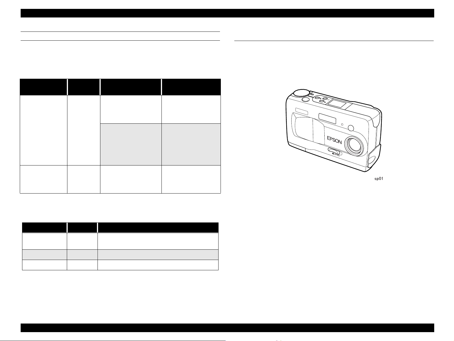
1.2 Exterior View
† Dimension: 113mm x 67.5 x 36mm
† Weight: 235g (Batteries and strap are not included)
† Others: Tripod socket is available for installing the tripod.
Figure 1-1. Exterior View
†
Battery and Adapter
Table 1-2. Battery and Adapter
Product Name Code No. Specification
Power Pack B81817*
Battery B81811* Ni-MH Rechargeable batteries
AC adapter B86706* AC adapter power cable
NOTE:
The asterisk is a substitute for the last digit of the product number,
Includes the Ni-MH battery charger and Ni-MH
Rechargeable batteries
which varies by country.
Product Description Exterior View 11
Page 12

EPSON PhotoPC 800 Revision A
1.3 Functions Specification
Basic specifications of PhotoPC 800 is as follows.
1.3.1 Image Data
† Data Type: DCF (Design rule for camera file system)
(16 million colors, 24 bit)
† Thumb nail Image: 160 x 120 pixels
† Color: Full color (24bit full color)/Monochrome
H
† Image Size: 1984 x 1488 pixels (HyPict
1984 x 744 pixels (Panorama HyPict
1600 x 1200 pixels (Super Fine
1600 x 600 pixels (Panorama Super Fine
1600 x 600 pixels (Panorama Fine
640 x 480 pixels (Standard
OPTICAL
†
CCD: 1/2 inch color area CCD (2.1M pixels)
† Total pixels:1688 x 1248 (Effective pixel 1636 x 1236)
1600 x 1200 (actually used)
Inter-line read out
•••
•
)
•••
)
•••
/Fine••)
••
)
H
)
•••
† Shutter: Electric iris with mechanical shutter 1/30 second to
1/750 second (auto flash and forced flash modes),
1/2 second to 1/750 second (flash off mode)
† Exposure control: Divided brightness metering Program Auto,
Spot metering Program Auto,
Exposure Manual Adjustment
(-2EV to +2EV, 9 or 21-step)
† White balance: TTL automatic white b alance
Fixed mode (sunlight)
User defined mode
† Viewfinder: Real-image optical (view range over 90%)
AF target mark available
Frame for short distance shooting (80cm from the
)
object) is available
† Self-timer: 10 seconds
† Flash: Automatic luminance control flash
† Flash modes: Automatic, forced flash, flash off, slow flash
† Flash Range: 0.5 ∼ 3.4 m
∼ 0.5 m (Macro)
0.15
NOTE:
When using the Macro mode, over exposure occurs if the picture is
taken within 0.2m.
† Lens: f=7mm
(equivalent to a 38mm lens on a 35 mm camera)
Brightness: F2.4 5 elements in 5 groups
† Range: 0.5m to infinity
0.15m to 0.5m (Macro mode)
† Aperture: f2.4, f8.0
† Focus: Auto focus/Manual focus
NOTE:
When shooting the object with bad contrast or low light, autofocus may not work correctly. Especially, when the shooting needs
a flash, set the distance 1.5 cm forcefully.
† Sensitivity: Equivalent to ISO 100/200/400
Product Description Functions Specification 12
Page 13

EPSON PhotoPC 800 Revision A
1.3.2 Shooting Mode
† LCD Shooting mode
„ TTL image play (Play back rate 1/30 sec)
„ Through image rate: 100%
† Self-Timer: 10 seconds (fixed)
„ First 8 seconds: Self-timer lamp blinks slowly
„ Last 2 seconds: Self-timer lamp blinks fast
† Macro Mode: Shooting mode 0.15m ∼ 0.5m
† Quick shooting
„ In this mode, processing time from one shooting to the second
shooting is shortened by saving the taken images in the built-in DRAM.
After the image is taken in this mode, it is stored in the compact flash
memory card. (1.5 seconds if there is no flash charge for full size
image)
„ After this mode is canceled, image data is stored in the compact flash
card. (writing time is approximately 130KB/second)
„ At each mode, DRAM is available up to 4MB. (Up to 10 pictures)
† Continuous shooting:
† Interval shooting
„ Shooting minimum interval; 10 seconds (except Hypict and recording
setting)
„ Shooting minimum interval ; 20 seconds (except Hypict and recording
setting)
„ Shooting maximum interval; 24 hours
„ Shooting setting interval; Setting available by seconds unit
† Shooting Function: Sports shooting, Portrait shooting, Landscape
shooting, Manual exposure.
1.3.3 Memory
† Internal RAM Memory: 8MB
† Internal ROM memory: 2MB
† Expansion Memory:
„ Complies with Compact Flash Memory Card
„ PC-DOS format : 512B/Sector
„ 12bit FAT (Up to 15 MB)/16bit FAT
„ Full-size: 1 image/second
„ VGA: 2 images/second
„ Continuous shooting is available up to 4MB in the RAM.
„ Flash is set Off forcibly
„ Beeping sound available pe r shoot ing
† Digital zoom:
„ 2 x digital zoom
„ Image size of the each recording mode is available
† Panorama: 1600 x 600 (Super fine/Fine)
† Monochrome:1600 x 1200 (Super fine/Fine)
Product Description Functions Specification 13
Page 14

EPSON PhotoPC 800 Revision A
1.3.4 Function Display and Other
† LCD Monitor: 1.8 inch TFT color LCD monitor (110K pixels: 5142 x 218
pixels)
„ View rate at shooting:100%
„ Playback view range:100%
† Beep Sound: Available (On/Off setting)
† Self-Timer Indication:
„ Red lamp
„ Slow blink/fast blink
† Control LCD Panel indicates;
„ the number of available pictures (3 digit)
„ the number of available pictures at quick shooting (Writing or shooting
up to 10 pictures)
„ Current exposure value
„ The setting of Image Quality mode
„ White balance mode
„ High Sensitivity mode
NOTE:
However, Timer IC operates when the battery is installed. When
the batteries are exchanged, the time will be kept counted for 30minutes until the the electricity in the capacitor runs out.
† Power Saving Function:Available to select the power save off time
between 10 sec, 30 sec, 1 min or 3 min.
10 seconds: Shuts down in 10 seconds
30 seconds: Shuts down in 30 seconds
1 minute: Shuts down in 1 minute
3 minutes: S huts down in 3 minutes
† When using the slide show, it shuts down in one round.
† Shuts down in 5 minutes when the camera is connected to PC, but the
camera does not shut down when using the USB connection.
† No power saving function when using AC adapter.
† Recover: escapes from the power saving function by half-shutter or turning
the power On again.
NOTE:
No power saving when using the AC adapter.
This function works in 5 minutes when the camera is connected to
the PC.
„ Flash mode
„ Low battery mark
„ Self-Timer mode
† Lamp next to the VF (view finder)
„ Green light on/Green light blink/Off
† Lamp in the rear
„ Red light on/Red light blink/Green light on/Green light blink/Orange
light blink/Off
† Built-in clock: Year/Month/Date, Time/Minute/Second
Product Description Functions Specification 14
Page 15

EPSON PhotoPC 800 Revision A
1.3.5 GUI Menu Operation
1.3.5.1 Shooting
Following shooting modes are available by using the dial switch.
1. SETUP Mode
2. VF (ViewFinder) shooting mode
3. LCD shooting mode
4. Special shooting mode
5. Playback mode
6. Expansion function
SETUP (BASIC SETTINGS)
†
General Setting
„ Date/Time setting
„ Shooting mode selection (Full Auto/Program/Manual)
„ Color setting (Color/Black&White)
„ Shooting function (Normal shooting/Quick shooting)
„ Language setting (English/Japanese/French/German/Italian/
Portuguese/Spanish)
† Camera Setting
„ Power saving function (10 seconds/30 seconds/1 min./3 minutes/none)
„ Camera brightness adjustment (-3 ∼ +3, 7 levels)
„ Beep sound (On/Off)
„ Audio recording setting (None/3 seconds/5 seconds/10 seconds)
„ White balance setting
† Memory setting
„ Directory selection
„ Adding the expansion function
„ Initializing the memory card
V/F SHOOTING MODE
Using the viewfinder when taking helps save battery power, and can make it
easier for the user to hold the camera steady when pressing the shutter button.
† Full Auto
„ Flash (Auto/Forced/Off)
„ Image quality
•••/•••
(••/
•••/•
(••/
H
/•) Normal
) Quick shooting
„ Self-Time Mode
† Program
Flash (Auto/Force/Off/Slow Synchro)
† Manual
„ Flash (Auto/Forced/Off)
„ Image quality
•••/•••
(••/
•••/•
(••/
H
/•) Normal
) Quick shooting
„ Self-Timer Mode
„ Sensitivity (Standard/High/Super High)
„ White Balance (Auto/Fixed (sun light/User defined)
„ Exposure correction
„ Program (-2 ∼+2, at intervals of 0.5, 9-step)
„ Manual (-2 ∼+2, at interval of 0.2, 21-step)
Product Description Functions Specification 15
Page 16

EPSON PhotoPC 800 Revision A
LCD SHOOTING MODE
Using the LCD monitor allows the user to verify the whole image before
shooting, and confirm the image right after shooting. It is recommended to use
the LCD monitor when taking the pictures using the panorama or digital zoom
features, or close-ups.
† Full Auto: Allows you to take basic photos without having to make complex
settings. Available setting are;
„ Flash modes (Automatic/forced flash/flash off)
„ Image quality
„ Self-timer mode
„ Digital zoom (x2)
„ Macro/Panorama
„ Audio recordings
† Program: For users who want a moderate amount of control over the
camera’s functions. Available settings are;
„ Flash (Auto/Forced/Off/Slow Synchro flash)
„ Image quality
•••/•••
(••/
•••/•
(••/
H
/•) Normal
) Quick shooting
„ Self-timer mode
„ Digital zoom (x2)
„ Audio recording
† Manual; For experienced users who want complete control over the
camera’s wide array of settings and features. Available settings are;
„ Flash (Auto/Forced/Off/slow)
„ Image Quality
•••/•••
(••/
•••/•
(••/
H
/•) Normal
) Quick shooting
„ Self-timer mode
„ Digital zoom (x2)
„ Macro/Panorama
„ Sensitivity (Standard/High sensitivity/Super High)
„ White balance (Auto/Fixed/User defined)
„ Exposure adjustment (-2 ∼+2, at intervals of 0.5, 9-step)
„ Program exposure available
„ Focus setting (3 steps/AF) for Stamdard (normal) shooting
(10 steps/AF) for Macro shooting
„ Spot and divided brightness metering systems
„ Exposure control: Manual exposure (Shutter speed, aperture (F2.4
/F8))
„ Audio recording
„ Macro/Panorama
„ Sensitivity (Standard/High sensitivity/Super High)
„ Auto, fixed or custom white balance
„ Exposure correction (-2 ∼+2, at intervals of 0.5, 9-step)
„ Various program shooting (sports, portrait/landscape/normal)
„ Aperture priority shooting (F2.4/F8)
„ Exposure control (Divided brightness metering Program Auto, Spot
metering Program Auto)
Product Description Functions Specification 16
Page 17

EPSON PhotoPC 800 Revision A
1.3.5.2 Process after shooting (common with LCD shooting
mode)
† Image check
Writing to the memory card/Erasing previous picture (Only at normal
shooting)
† Audio recording after shooting
Auto recording after shooting (only at normal shooting and when audio
recording setting is set)
SPECIAL SHOOTING MODE
Camera goes to the special shooting mode, keeping the condition of LCD
shooting mode. Image check and quick shooting are not performed.
† Continuous shooting
„ Image quality (
„ 2 levels of shooting speed for continuous shooting
„ No flash
„ Audio recording is available only for the last photo when using the
continuous shooting feature
† Time lapse feature (interval shooting)
„ Shooting interval time setting: 10 seconds (Min. interval) ∼ 24 hours
„ When using the audio recording or HyPict features, the shortest time
interval available is 20 seconds instead of 10.
••/•••/•
)
(Max. interval) Setting is available every
1 second.
PLAYBACK MODE
†
Normal playback
„ Displayed information
Image No.
Date and Time
Shutter speed
Aperture
Flash mode
W/B mode
Others
„ Multiple photos
Thumbnail images (4 or 9 images)
Lock
Erasing
Magnifying
Audio recording (Overwrites 3, 5, or 10 seconds)
† Slide Show
„ Slide show speed; Automatically changes every 3, 5 or 10 seconds/ or
manual change available)
„ Pause during slide
„ Image erase during slide
„ Exclude or add photos
„ Rotating photos 90 degrees to the right or left)
„ Multi display; 4 or 9 images
„ Except for using the audio recording and HyPict features, 10 seconds
∼ 24 hours time interval setting is available by every 1 second.
Product Description Functions Specification 17
Page 18
EPSON PhotoPC 800 Revision A
1.3.6 Processing Time
Table 1-3. Photo processing time (approximate)
Interval time for
quick shooting
Replay time
Standard
Fine
Super fine
•••
HyPict
••
•••
•
Time (seconds)
H
Less than 2 1.0 Less than 0.5
2.1 1.2 1.0
2.5 1.2 1.5
12 -- 2.0
1.3.7 File Size/Storage Capacity
1.3.7.1 File size
Image data is compressed and stored by JPEG. The number of pictures you
can take varies, since file size changes according to the complexity of each
photos.
Table 1-4. File Size
Image setting Setting indication
File size
(approximate)
1.3.7.2 Storage capacity of Compact Flash card
Table 1-5. Storage capacity of each Compact Flash Card (Use as
reference value)
Setting
indication
•
••
•••
8MB
123
23
12
NOTE:
NOTE:
Image setting
Standard
Fine
Super fine
The number of photos you can save on a memory card may differ
slightly from the chart above, depending on the complexity of each
photo.
If you attach an audio recording to a photo saved in your memory
card, the number of photos you can save on that card may
decrease.
Figures in the table represent storage capacity when there is no
image data in the internal memory. If other file is stored in the
memory, available storage capacity decreases according to the file
volume.
Standard (640 x 480)
Fine (1600 x 1200)
Super fine (1600x1200)
HyPict (1984 x 1488)
Fine panorama (1600 x 600)
Super fine panorama
(1600 x 600)
Hypict panorama (1984 x 744)
•
••
•••
•••
••
•••
•••
65KB
340KB
680KB
H
H
770KB
170KB
340KB
385KB
Product Description Functions Specification 18
Page 19
EPSON PhotoPC 800 Revision A
1.3.8 External Interface
† Video output
NTSC/PAL video output
† Inlet for DC power supply:DC input terminal for AC adapter
(3.4V) EIAJ Type 2
φ 4.4mm
† Serial communication connector
„ Connection is acknowledged by GND detection
„ 14-pin dual line terminal
„ TCX3080
† Compact flash interface
Compact Flash Card Type 1
1.3.8.1 Serial communication interface
The serial interface of PhotoPC800 is exclusive interface. The interface is
compatible with RS-232C and RS-42 2/42 3 for connec ti ng with the host
computer, printer and modem. 19.2 Kbps or higher is required for connecting
with the host computer.
Table 1-6. Interface specification
Standard Synchronism
RS-232C Asynchronous
RS-422, RS-423 Synchronous
Communication
speed
Asynchronous ,
8bit, Non Parity
Synchronous, 8bit,
Non Parity
Transmission
speed
19200, 38400,
115200, 57600,
230400 bps
230Kbps-1.8 Mbps
Table 1-7. Signal Name for Serial Communication Interface
PhotoPC-800 DOS/V side to Printer/Mac. to Modem
Pin
assign.
1 VDD -- -- -- -- -- VDD
2 D+ -- -- -- -- I/O D+
3 GND -- GND -- S.G. -- -4 HSKI -- -- I SCLK -- -5 RXD+ -- -- I TXD+ -- -6 TXD+ -- -- O RXD+ -- -7 DIN C. -- -- -- -- -- -8 DIN C2 -- -- -- -- -- --
9 D- -- -- -- -- I/O D10 GND -- -- -- -- -- GND
11GPI-----------12 HSKO -- -- -- CTS -- -13 RXD- I host SD I TXD- -- -14 TXD- O host RD O RXD- -- --
signal
name
shell -- -- -- -- -- --
I/O
Signal
name
I/O
Signal
name
I/O
Signal
name
†
Connector
„ 14-pin dual line terminal
„ Detection function for the plug insertion
Product Description Functions Specification 19
Page 20

EPSON PhotoPC 800 Revision A
1.3.9 Power Supply
† Battery
Ni-MH rechargeable battery (x2)
Output voltage: 1.2V x 2 (2.4V)
Volume: 1450mA/per one battery
NOTE:
Manganese battery can not be used.Although Alkaline battery can
be used, it is not recommended.
† AC adapter
DC3.4V
† Input power supply: 3.4V, 2.5V
† Battery Life: (when using two of the included Ni-MH batteries)
Table 1-8. Battery Life
Mode
Taking photos with View Finder More than 850 pictures
Taking photos with LCD monitor
(Automatic shut-off is set to 10
seconds)
Playing back photos 55 min.
Power Save Mode 10 sec.
Available pictures
(Approximate)
100 pictures
Product Description Functions Specification 20
Page 21
EPSON PhotoPC 800 Revision A
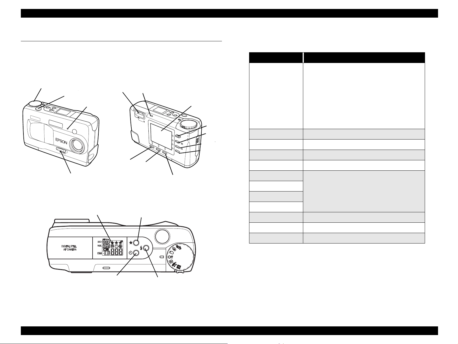
1.4 Indication and Switch Function
1.4.1 Indication and Switch
Figure below shows switches and indications.
Dial switch
Shutter
switch
Self-timer
Lens cover
switch
Figure 1-2. Front and Rear
VF&shooting
lamp
Button “A”
lamp
Status Lamp
Button “B”
Button “C”
LCD Monitor
Button1
Button2
Button3
Button4
1.4.1.1 Switches
Table 1-9. Switches
Name Functions
• Power and setting switch
• 7-mode rotary switch
*Special shooting mode (Continuous/interval
shooting)
Dial switch
Shutter switch 2-step shutter/ Release button
Resolution switch Image quality (•/••/
Flash switch Flash setting (Auto/Forced/Off/Slow Synchro)
Self-timer switch Self-timer setting (ON/OFF)
Button 1
Button 2 (+)
Button 3 (-)
*LCD shooting mode
*VF shooting mode
*OFF
*Playback mode
*Expansion function mode/PC connection mode
*SETUP mode
•••/•••
MENU selection
H
)
Display Panel
Self-timer
switch
Resolution
switch
Flash switch
Button 4
Button A Menu selection/ON/OFF/Going to the next screen
Button B Selection of expansio n functions and connection
Button C Various setting mode
NOTE:
VF: View Finder
Figure 1-3. Top
Product Description Indication and Switch Function 21
Page 22
EPSON PhotoPC 800 Revision A
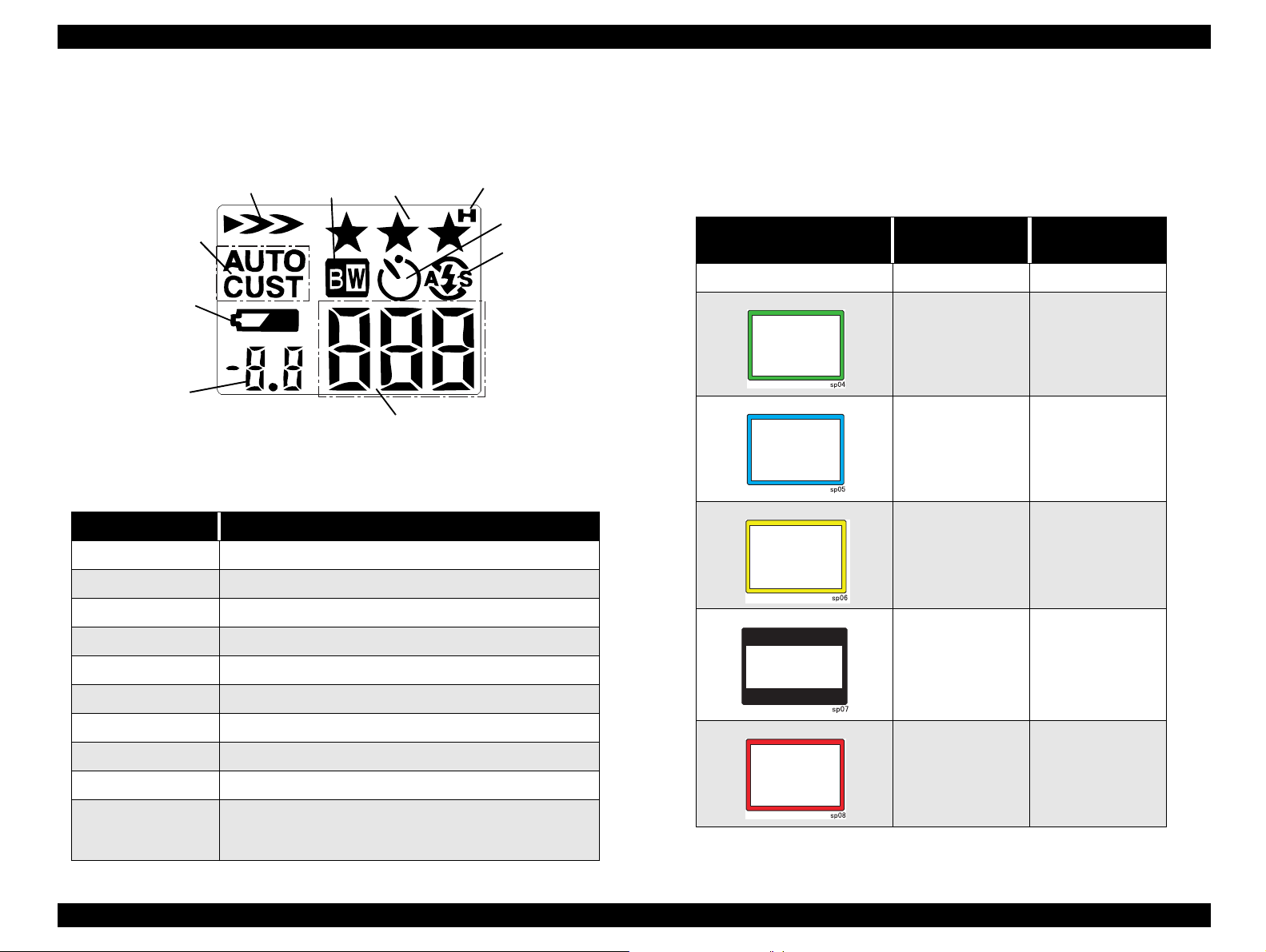
1.4.1.2 Display Panel
Picture below shows the display panel.
Sensitivity
White
Balance
Low Battery
icon
Exposure
Name Function
ISO sensitivity Displays ISO sensitivity
W. B White balance status
Monochrome
mode
Figure 1-4. Display Panel
Table 1-10. LCD Panel
Image
quality
Hypict mode
Timer
Flash
Number of pictures
remaining
Self-
1.4.1.3 Displays for Shooting Condition
There are several color frame indicators showing current capturing mode on
the LCD monitor in the LCD shooting mode and special and continuous
shooting modes.
Table 1-11. Frame Indication
LCD indication Mode
Nothing Standard ---
Macro
Monochrome
Digital 2 x zooming
Characters and
indication period
MACRO
a few seconds
MONOCHROME
a few seconds
ZOOM
a few seconds
Low Battery Icon When the battery power is almost out.
Exposure correction Displays exposure correction value and apertu re value
Image Quality Displays image quality
Hyper Displays Hypict mode
Monochrome Monochrome shooting
Self-timer Indicates when the self-timer is set
Flash Indicates flash status
Number of pictures
remaining
• When shooting: No. of pictures remaining and No. of
pictures stored in the buffer.
• Half-shutter; Shutter speed
Panorama
Continuous
shooting
PANORAMA
a few seconds
CONTINUOUS
a few seconds
Product Description Indication and Switch Function 22
Page 23

EPSON PhotoPC 800 Revision A
1.4.1.4 Lamp Indications
Table 1-12. Lamp
Condition Status Lamp (Red) Status Lamp (green) Status Lamp (orange) Shooting Lamp (green) Timer Lamp (red)
Ready ON
Focus Blink (0.2s)
Flocus lock ON
VF shooting when the lens
cover is closed
LCD/Special shooting when
the lens cover is closed
During CF transmission Blink (0.8s) X X
Unable to write CF (Full) Blink (0.8s) XX
Connecting the AC adapter ON
Battery warning Blink (1.0s)
Err ON X X
Self-timer on ON
When the po wer is turned on
(only for shooting)
VF/LCD/Special shooting
Dial switch Off = Power Off X X X X
Charging the flash Blink (0.2s)
Playback/Setup ON X X
NOTE:
“X” means that light goes off in the corresponding condition, no
Blink (0.8s) Shuts down a fter
the lamp blinks 9 times
X X
Fast blinking → On right
before shooting
Blink (0.2s)
matter what condition the camer is in.
Example; During setting the self-timer, the lens cover is closed
→
the Self timer goes off even if it is On/blinking.
Product Description Indication and Switch Function 23
Page 24

EPSON PhotoPC 800 Revision A
1.4.2 List of Setting Items
The table below shows the available settings for VF shooting mode and LCD
shooting mode.
Table 1-13. VF, LCD shooting at full auto mode
NOTE:
Dial switch
Dial switch OFF
Panorama, Macro O O (VF:X) O O O X
Image quality setting
(include Hypict)
Flash X (Auto) O O X
Quick shooting O O O
Interval setting O O (VF:X) O X X X
SET UP setting O O O O O X
Digital zoom XOOXXX
Self-timer X X X X X X
O O O O O X
operation
(during shooting
mode)
Power saving
function
Shut down when
the battery power
is low
X (transmits the
buffer to CF)
Replacing
batteries
(Effective Super
capacitor )
X (to normal
shooting)
X X
Replacing
batteries
(invalid super
capacitor)
X
O: Available
X: Not available
CF: Compact Flash Card
Product Description Indication and Switch Function 24
Page 25

EPSON PhotoPC 800 Revision A
Table 1-14. VF, LCD shooting at program mode
Dial switch
Dial switch OFF
Panorama, Macro O O (VF:X) O O O X
Image quality setting
(include Hypict)
Flash OOOXXX
Quick shooting O O O
Interval setting O O (VF:X) O X X X
SET UP setting O O O O O X
Priority mode X O (VF:X) O X X X
W.B. O O O O O X
W.B. CUSTOM settingOOOOOX
Divided brightness
metering , Spot
metering
Exposure correction O O O X X X
O O O O O X
O O O O O X
operation
(during shooting
mode)
Power saving
function
Shut down when
the battery power
is low
X (transmits the
buffer to CF)
Replacing
batteries
(Effective Super
capacitor )
X (to normal
shooting)
Replacing
batteries
(invalid super
capacitor)
X
Sensitivity O O O O O X
MF shooting X O (VF:X) O X X X
Digital zoom X X X X X X
Self-timer XXXXXX
NOTE:
O: Available
X: Not available
CF: Compact Flash Card
Product Description Indication and Switch Function 25
Page 26

EPSON PhotoPC 800 Revision A
Table 1-15. VF, LCD shooting at manual mode
Dial switch
Dial switch OFF
Panorama, Macro O O (VF: none) O O O X
Image quality setting
(include Hypict)
Flash OOOOOX
Quick shooting O O O
Interval setting O O (VF:X) O O O X
SET UP setting O O O O O X
Priority mode OOOOOX
ME shooting O O O O O X
W.B. OOOOOX
W.B. CUSTOM setting O O O O O X
Divided brightness
metering , Spot
metering
O O O O O X
OOOOOX
operation
(during shooting
mode)
Power saving
function
Shut down when
the battery power
is low
X (transmits the
buffer to CF)
Replacing
batteries
(Effective Super
capacitor )
X (to normal
shooting)
Replacing
batteries
(invalid super
capacitor)
X
Exposure correction O O O O O X
Sensitivity O O O O O X
MF shooting O O O O O X
NOTE:
Shutter speed
correction
Digital zoom O O O O O X
O: Available
OOOOOX
X: Not available
CF: Compact Flash Card
Product Description Indication and Switch Function 26
Page 27

EPSON PhotoPC 800 Revision A
Table 1-16. Playback
NOTE:
NOTE:
Dial switch
Dial switch OFF
Slide setting O O O O O X
operation
(during shooting
mode)
Power saving
function
Shut down when
the battery power
is low
Replacing
batteries
(Effective Super
capacitor )
O: Available
X: Not available
Table 1-17. All modes
Dial switch
Dial switch OFF
Slide setting O O O O O X
operation
(during shooting
mode)
Power saving
function
Shut down when
the battery power
is low
O: Available
X: Not available
Replacing
batteries
(Effective Super
capacitor )
Replacing
batteries
(invalid super
capacitor)
Replacing
batteries
(invalid super
capacitor)
Product Description Indication and Switch Function 27
Page 28
EPSON PhotoPC 800 Revision A
1.5 Accessories
1.5.1 Included Cables
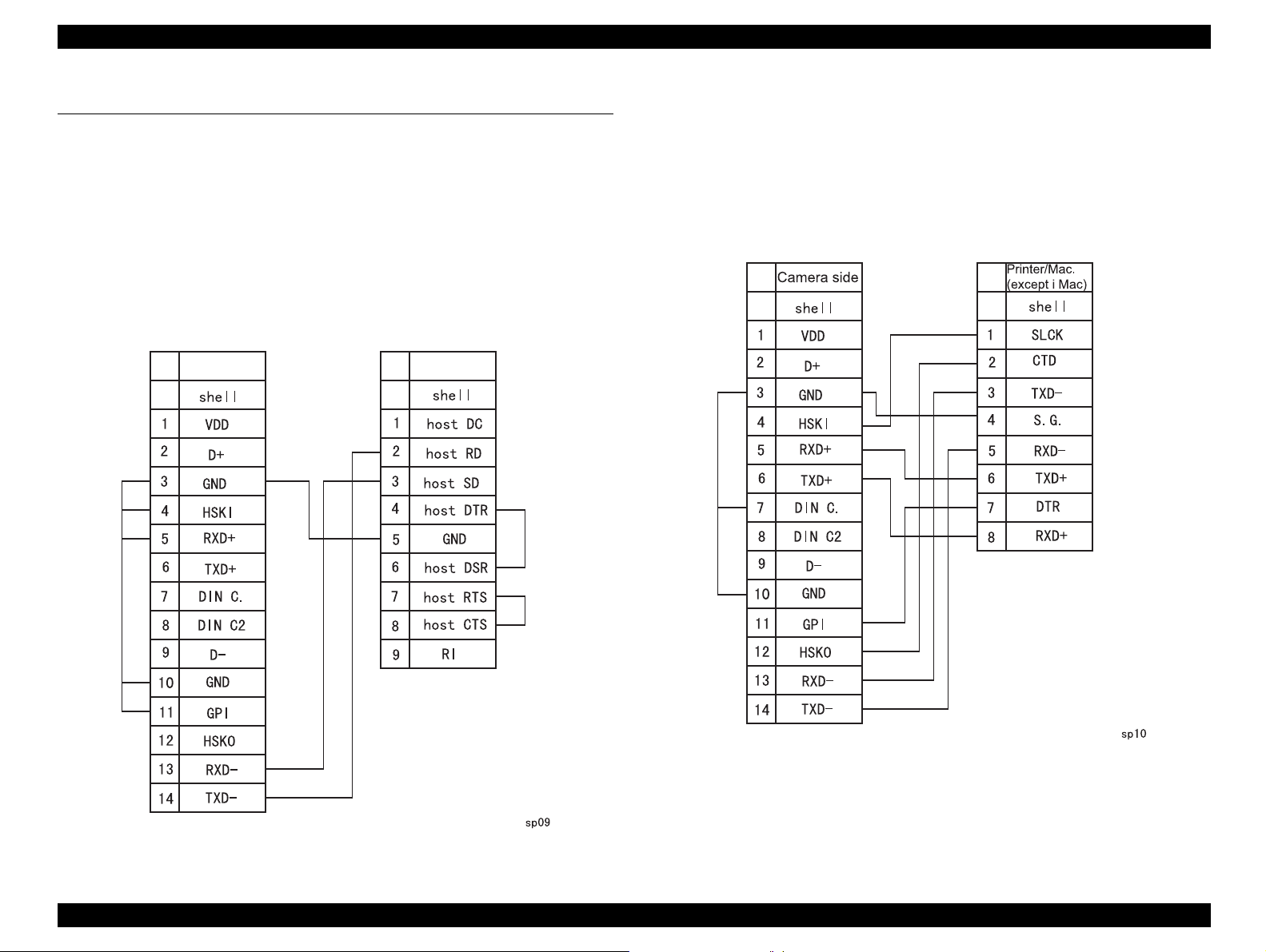
1.5.1.1 Connection Cable for DOS/V
† Length: 1.5m
† Connector:
„ Camera side: 14-pin dual line terminal (female)
„ PC side: 9-pi n D-SUB (fe mal e)
Camera side PC side
1.5.1.2 Connection Cable for Macintosh
† Length: 1.5m
† Connector
„ Camera side: 14-pin dual line terminal (female)
„ PC side: 8-pin, mini-DIN (male)
Figure 1-6. Macintosh Cable
Figure 1-5. DOS/V Cable
Product Description Accessories 28
Page 29
EPSON PhotoPC 800 Revision A
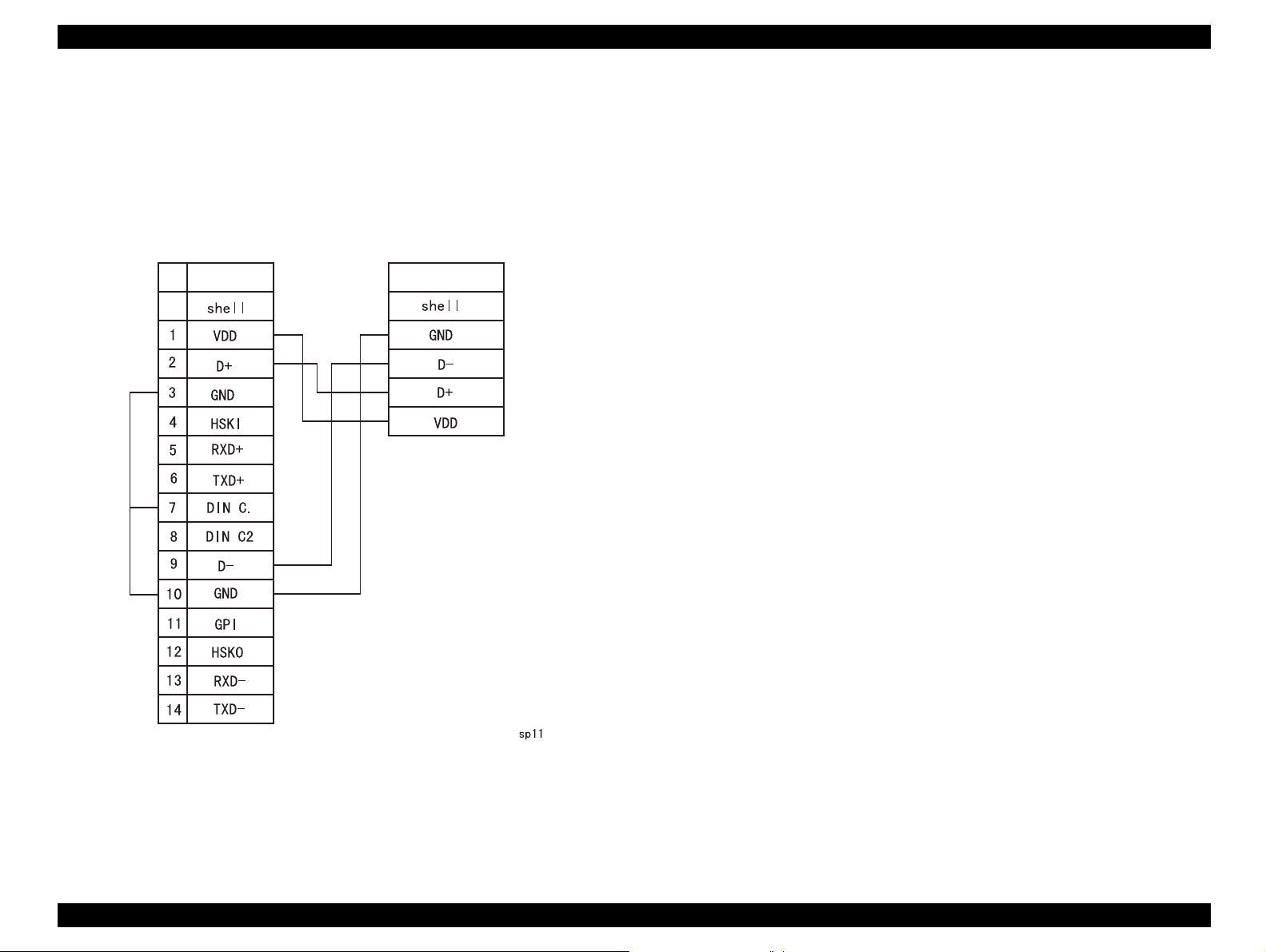
1.5.1.3 USB Interf ace Cable
† Length: 1.5m
† Connector:
„ Camera side: 14-pin dual line terminal
„ PC side: USB
Camera side USB (iMac.)
1.5.1.4 Video Cable
† Length: 1.5m
† Connector: mini-pin, RCA
1.5.2 Other accessories
† Soft camera case (TBD)
† Strap
Figure 1-7. USB interface cable
Product Description Accessories 29
Page 30

EPSON PhotoPC 800 Revision A
1.6 Specification for Options
1.6.1 Standard Options
AC ADAPTER
†
Model name: E-37
† Input voltage: AC100-240V, 50-60Hz, 30VA
† Output voltage: DC3.4V, 2.5A
NI-MH BATTERY
†
Model name: EU-24
† Type name: Cylindrical sealed Nickel-Metal
Hydride rechargeable battery
† Rating: DC1.2V
† Size: AA/IEC LR6 compatible
† Volume: 1450mAH/per battery
NI-MH BATTERY CHARGER
1.7 Environmental Condition
OPERATING/STORAGE ENVIRONMENT
†
Temperature:
„ Operating: 5 to 35 °C
„ Storage: -20 to 60 °C
† Humidity:
„ Operating: 30 to 90 % without condensation
„ Storage: 10 to 90% without condensation
† Shock resistance
„ Storage: 70G
POWER SOURCE SPECIFICATION
†
DC input voltage (AC adapter)
„ Min. DC2.96V (TBD)
„ Max. DC3.85V (TBD)
† Maximum DC input voltage: DC3.85V (TBD)
†
Model name: EU-38
† Input: AC100-240V, 50-60Hz
† Output: DC1.2V, 490mA x 4
† Compatible batteries:EPSON Ni-MH Batteries (Model EU-24)
† Charging time: 4 batteries: Approx. 3.5H
USAGE PLACE
†
Environment: Home, Office, Outside
† Water proof:Not available
Product Description Specification for Options 30
Page 31

EPSON PhotoPC 800 Revision A
1.8 Safety Standard and Reliability
EMI AND SAFETY STANDARDS
†
USA: FCC part15 subpart B class B
† Canada:CSA C108.8 class B
† Europe: EMC Directive 89/336/EEC (CE-marking)
EN5502 Class B
EN61000-3-2 (when using the AC adapter)
EN61000-3-3 (when using the AC adapter) EN5
0082-1
IEC801-2
IEC801-3
IEC801-4
† Europe: EN 55022 (CISPR Pub.22) class B
† Australia: AS/NZS 348 class B
† Taiwan: EMI: CNS13438-C6357
RELIABILITY
†
Flash Memory Life
10K cycles write for Flash Memory
Product Description Safety Standard and Reliability 31
Page 32

OPERATING PRINCIPLE
&+$37(5
5
Page 33

EPSON PhotoPC 800 Revision A
W ARNING
2.1 Board Component
Major component of PhotoPC800 consists of electric circuit and lens ASSY.
Figure below shows major electric boards and explains their functions.
SY1 Board
Lens Assy.
CA1 Board
PW1 Board
op01
CA2 Board
Figure 2-1. Major Component
Lens ASSY. (Lens Block) has the shutter mechanism and focus mechanism.
Lens focus distance is 7
gourps.
The electric circuit consists of SY1 board, CA1 board, CA2 board and PW1
board. Table2-1 shows the function of each board.
±0.35mm and lens construction is 5 elements in 5
Table 2-1. Functions of each board
Board Function
8 bit microprocessor (driven at 4MHz)
• Operation key input
SY1
CA1
CA2
PW1
PW1 board has a danger of getting electric shock because
of C5412. Hold the edges of this board and never touch the
board surface when you handle this board. Discharge the
charged energy of C5412 for safety before handling this
board. (See Chapter 4 for more details)
• Control LCD panel display
• Manages and back up the clock
• Manages power circuits
• Controls the charging for flash
CCD image sensor interline type
• CCD clock drive
• A/D conversion of image data
• Drives Lens ASSY.
32 bit RISC-CPU (driven at 72 MHz), ASIC,
Flash ROM, SDRAM
•γ correction
• Color signal generation
• SDRAM control
• USB control
• A/D conversion of 10 bit audio data
• Color LCD monitor control
Power supply circuit
• Switch regulator control
• Digital/analog line, 5V power output in LCD
line
• Digital 3.3V power supply output
• Digital 3.4V power supply output
• Analog/LCD line power supply output
• Back-light power supply output
• Flash power supply
Operating Principle Board Component 33
Page 34

EPSON PhotoPC 800 Revision A
2.2 Operating principles of the Circuit Boards
The figure below shows the block diagram of all boards in PhotoPC-800.
Subject
Figure 2-2. Block Diagram
Operating Principle Operating principles of the Circuit Boards 34
Page 35

EPSON PhotoPC 800 Revision A
pin
pin
2.2.1 CA1 Circuit Operation
2.2.1.1 Overview
CA1 board consists of the following ICs.
„ IC903 (LZ21N3): CCD imager
„ IC902 (74ACT04MTC): H driver
„ IC904 (LR366854): V driver
The figure below shows the block diagram of CA1 board.
2.2.1.2 IC903
Specification of the CCD(charged-Coupler Device) is shown below.
† Structure
„ CCD Image Sensor Interline type
„ Optical size: 1/2 inch format
„ Cell pitch: 3.95 µm
„ Effective pixel: 1650 (H) x 1250 (V)
„ Total pixel: 1704 (H) x 1255 (V)
„ Optical Black:
Horizontal (H) direction: Front: 2 pixel Rear: 52 pixel
Vertical (V) direction: Front: 3 pixel Rear: 2 pixel
Figure 2-4. Optical Black
Number of the dummy bit::Horizon: 28 Vertical: 2
„
Figure 2-3. CA1 Circuit Block Diagram
Operating Principle Operating principles of the Circuit Boards 35
Page 36

EPSON PhotoPC 800 Revision A
CCD block diagram and terminals are shown below. Ye is yellow detection cell,
Mg is Magenta detection cell, CY is Cyan detetion cell and G is green detection
cell.
20
15
19
1
16
Vertical Register
Horizontal Register
5
2
Note)
14
3
12
4
Photosensor
13
11
Note
10
8
Figure 2-5. CCD Block Diagram
Table 2-2. CCD Pin Description
Terminal
10D
2,19 GND GND GND 0V
3 0FD Board Clock DC
4 PW
5 RS Rest gate clock 7V, 13V
8 H1
10 H2
11 V4
Terminal
symbol
Terminal
function
Circuit power
supply
Protection
transistor bias
Horizontal registe r
transfer clock
Horizontal registe r
transfer clock
Vertical register
transfer clock
Waveform Voltage
DC 13V
Approx. 6.9V
DC -7V
(Different
from every
CCD)
0V, 5V
0V, 5V
-7V, 0V
12, 13 V3A, V3B
14 V2
15, 16 V1A, V1B
20 OS Signal output Approx.6.5V
NOTE:
---- When sensor read-out
Vertical register
transfer clock
Vertical register
transfer clock
Vertical register
transfer clock
-7V, 0V, 13V
-7V, 0V
-7V, 0V, 13V
Operating Principle Operating principles of the Circuit Boards 36
Page 37

EPSON PhotoPC 800 Revision A
2.2.1.3 IC902 (H Driver) and IC904 (V Driver)
An H driver (IC902) and V driver (IC904) are necessary in order to generate the
clocks (vertical transfer clock, horizontal transfer clock and electronic shutter
clock) which driver the CCD. IC902 is an inverter IC which drives the horizontal
CCDs (H1 and H2). In addition the XV1-XV4 signals which are output from
IC102 are the vertical transfer clocks, and the XSG1 and XSG signal which is
output from IC102 is superimposed onto XV1 and XV3 at IC904 in order to
generate a ternary pulse. In addition, the XSUB signal which is output from
IC102 is used as the sweep pulse for the electronic shutter, and the RG signal
which is output from IC102 is the reset gate clock.
Figure 2-6. IC902 Block Diagram
2.2.1.4 IC905 (CDS, AGC Circuit, A/D Converter)
The video signal which is output from the CCD is input to Pins (26) and (27) of
IC905. There are S/H blocks inside IC905 generated from the XSHP and
XSHD pulse, and it is here that CDS (correlated double sampling) is carried
out. After passing through the CDS circuit, the signal passes through the AGC
amplifier. It is A/C converted internally into a 10-bit signal, and is then input to
IC102 of the CA2 circuit board. The gain of the AGC amplifier is controlled by
the serial communication from IC102 of the CA2 circuit board.
Figure 2-8. IC905 Block Diagram
24
1
21
23
22
20
19
18
16
17
2
3
4
7
5
6
9
8
13
14
15
11
12
10
Figure 2-7. IC904 Block Diagram
Operating Principle Operating principles of the Circuit Boards 37
Page 38

EPSON PhotoPC 800 Revision A
e
a
Reset gate pulse
13V Pre-charge drain bia
Direction of transfer
H Register
Electric charge
Voltage output
Floating diffusion gate is
floated at a high impedance.
C is charged
equivalently
2.2.1.5 Transfer of Electric Charge by the Horizontal CCD
The transfer system for the horizontal CCD emplays a 2-phase drive method.
The electric charges sent to the final stage of the horizontal CCD are
transferred to the floating diffusion, as shown in the figure below. RG is turned
on by the timing in (1), and the floating diffusion is charged to the potential of
PD. The RG is turned off by the timing in (2). In this condition, the floating
diffusion is floated at high impedance. The H1 potential becomes shallow by
the timing in (3), and the electric charges now moves to the floating diffusion.
Here, the electric charges are converted into voltage at the rate of V=Q/C by
the equivalent capacitance C of the floating diffusion. RG is then turned on
again by the timing in (1) when the H1 potential becomes deep. Thus, the
potential of the floating diffusion charges in proportion to the quality of
transferred electric charge, and becomes CCD output after being received by
the source follower. The equivalent circuit for the output circuit is shown in
figure2-10.
Figure 2-10. Theory of Signal Extraction Operation
Floating diffusion
Figure 2-9. Horizontal Transfer if CCD Imager and Extraction of
Operating Principle Operating principles of the Circuit Boards 38
Signal Voltage
RG pulse peak si
Black lev
Signal volt
Page 39

EPSON PhotoPC 800 Revision A
2.2.1.6 Lens Drive Clock
† Shutter drive:
The two control signals (SIN1, SIN2) which are output from the ASIC
expansion port (IC106) are converted into drive pulses (SOUT1, SOUT2)
by the motor drive (IC951), and the shutter is opened and closed by regular
current drive.
Table 2-3. Shutter specification
Item Contents
Method 2-spring shutter
Current for motor driving Maximum 200mA
Motor coil resistance 12 ±1Ω (at normal temperature)
Iris drive
†
The two control signals (IIN1, IIN2) which are output from the ASIC
expansion port (IC106) are converted into drive pulses (IOUT1, IOUT2) by
the motor drive (IC952), and the iris is opened and closed. Resistance
R9505, which is connected to IOUT2 of IC952 in series, is the current
control resistance for the minimum drive voltage of the iris motor.
Table 2-4. Iris specification
Item Contents
Table 2-5. Focus Motor specification
Item Contents
Method Stepping Motor
Driving volt age 3.4 ±1V
Driving frequency 480bps
Motor coil resi stance 40
7% (at normal temperature)
Ω ±
Table 2-6. Detection of Focus position
Item Contents
Method Photo interrupter type
Driving volt age 5V
Judgement
• High: higher than 3.5V
• Low: less than 1.5V
Focus step 2 steps (when F2.8 opens, F8)
Minimum drive voltage 1.4VDC
Motor coil re sistance 12 ±1Ω (at normal temperature)
Focus drive
†
The four control signals (FIN1, FIN2, FIN3 and FIN4) with different phases
which are output from the ASIC are converted into drive pulses (FOUT1,
FOUT2, FOUT3 and FOUT4) by the motor driver (IC953), and are then
used to drive the stepping motor for focusing operation. Detection of the
standard focusing positions is carried out by means of the photointerruptor
(FOCUS PI) inside the lens block.
Operating Principle Operating principles of the Circuit Boards 39
Page 40

EPSON PhotoPC 800 Revision A
Shutter Motor
Iris Motor
Focus Motor
Figure 2-11. Lens Drive Circuit Block Diagram
Operating Principle Operating principles of the Circuit Boards 40
Page 41

EPSON PhotoPC 800 Revision A
2.2.2 CA2 Circuit Description
2.2.2.1 Outline of Operation
When the shutter opens, the reset signals (ASIC and CPU) and the serial
signals (“take a picture” commands) from the 4-bit microprocessor are input
and operation starts. When the TG/SG drives the CCD, picture data passes
through the A/D and CDS, and is then input to the ASIC as 10-bit data. The AF,
AE, AWB, shutter, and AGC value are computed from this data, and three
exposures are made to obtain the optimum picture. The data which has already
been stored in the SDRAM is read by the CPU and color generation is carried
out. Each pixel is interpolated from the surrounding data as being either Ye,
Cy, Mg or B primary color data to produce R, G and B data. At this time,
correction of the lens distortion which is a characteristic of wide-angle lenses is
carried out. After AWB and γ processing are carried out, a matrix is generated
and aperture correction is carried out for the Y signal, and the data is then
compressed by the JPEG method by JPEG IC and is then written to the
memory. When the data is to be output to an external device, it is taken data
from the memory and output via the USART. When played back on the LCD
and monitor, data is transferred from memory to the SDRAM, and the image is
then elongated so that it is displayed over the SDRAM display area.
Figure 2-12. CA2 Circuit Board Block Diagram
Operating Principle Operating principles of the Circuit Boards 41
Page 42

EPSON PhotoPC 800 Revision A
2.2.2.2 Circuit Description
† Digital Clamp
The optical black section of the CCD extracts averaged values from the
subsequent data to make the black level of the CCD output data uniform
for each line. The optical black section of the CCD averaged value for
each line is taken as the sum of the value for the previous line multiplied by
the coefficient k and the value for the current line multiplied by the
coefficient 1-k.
† Signal Processor
„
correction circuit
γ
This circuit performs (gamma) correction in order to maintain a liner
relationship between the light input to the camera and the light output
from the picture screen.
„ Color generation circuit
This circuit converts the CCD data into RGB signals.
„ Matrix circuit
This circuit generates the Y signals, R-Y signals and B-Y signals from
the RGB signals.
„ Matrix circuit
This circuit generates the Y signals, R-Y signals and B-Y signals from
the RGB signals.
„ SIO
This is the interface for the 8-bit microprocessor.
„ PIO/PWM/SIO for LCD
8-bit parallel input and output makes it possible to switch between
individual input/output and PWM input/output.
„ USB control
This is communicated PC with 12Mbps.
„ TG/SG
Timing generated for 2 million pixel CCD control.
„ Digital encorder
It generates chroma signal from color difference signal.
„ JPEG control
Controls the interface for the externally-connected JPEG IC.
„ 10-bit A/D circuit (Audio)
This circuit converts the audio signals (analog signals) from the
microphone to 10-bit digital signals.
„ Horizontal and vertical aperture circuit
This circuit is used generate the aperture signal.
† AE/AWB and AF computing circuit
The AE/AWB carries out computation based on a 64-segment screen, and
the AF carries out computations based on a 6-segment screen.
† SDRAM controller
This circuit outputs address, RAS, CAS and AS data for controlling the
SDRAM. It also refreshes the SDRAM.
† Communication Control
„ USART
The RS-232C can be sued for both synchronous and asynchronous
transmission.
Operating Principle Operating principles of the Circuit Boards 42
Page 43

EPSON PhotoPC 800 Revision A
2.2.2.3 LCD Block
During monitoring, YUV conversion is carried out for the 10-bit CCD data which
is input from the A/D conversion block to the ASIC and is then transferred to
the DRAM so that the CCD data can be displayed on the LCD.
The data which has accumulated in the DRAM is passed through the NTSC
encoder, and after D/A conversion is carried out to change the data into a Y/C
signal, the data is sent to the LCD panel and displayed.
If the shutter button is pressed in this condition, the 10-bit data which is output
from the A/D conversion block of the CCD is sent to the DRAM (DMA transfer),
and after processor, it is displayed on the LCD as a freeze-frame image.
During playback, the JPEG image data which has accumulated in the flash
memory is converted to YUV signals, and then in the same way as during
monitoring, it is passed through the NTSC encoder, and after D/A conversion is
carried out to change the data into a Y/C signal, the data is sent to the LCD
panel and displayed. The two analog signal (Y/C signals) from the ASIC are
converted into RGB signals by the LCD driver, and these RGB signals and the
control signal which is output by the LCD driver are used to drive the LCD
panel. The RGB signals are 1H transposed so that no DC component is
present in the LCD element, and the two horizontal shift register clocks drive
the horizontal shift registers inside the LCD panel so that the 1H transposed
RGB signals are applied to the LCD panel. Because the LCD closes more as
the difference in potential between the COM (common polar voltage: fixed at
DC) and the R, G and B signals becomes greater, the display becomes darker;
if the difference in potential is smaller, the element opens and the LCD become
brighter.
2.2.3 SY1 Circuit Description
2.2.3.1 Configuration and Functions
For the overall configuration of the SY1 circuit board, refer to the block
diagram. The configuration of the SY1 circuit board centers around a 8-bit
microprocessor (IC301).
Figure 2-13. SY1 Circuit Block Diagram
The 8-bit microprocessor handles the following functions;
1. Operation Key
2. Mode LCD display
3. Clock control
4. Power ON/OFF
5. Strobe charge control
Operating Principle Operating principles of the Circuit Boards 43
Page 44

EPSON PhotoPC 800 Revision A
Table 2-7. 8-bit Microprocessor Port Specification Table 2-8. 8-bit Microprocessor Port Specification
Pin Signal Name I/O Outline
1 CHG VOL I Strobe charge voltage input (analog input)
2,3 NOT USED -- Connect to GND
4-7 SCAN IN 0-3 I Key matrix input
8 AVDD -- Analog power input terminal
9 AVREF I Analog standard voltage input terminal
10 /STBY (R) LED O Standby LED (red) drive L:LED light
11 /STBY (G) LED O Standby LED (green) drive L:LED light
12 VSS -- GND87
13 /SELF LED O Self-timer LED drive L:LED light
14 VF LED O Viewfinder LED drive L:LED light
15-19 NOT USED -- Connect to GND
20 /AVREF ON O
21 BUZZER O Buzzer output
22 CHG ON O Strobe charge ON/OFF signal H:ON
23-25 COM1- COM3 O Mode LCD common output
Analog standard voltage ON/OFF signal
L:ON
Pin Signal Name I/O Outline
57-59 SCAN IN4-6 I Keymatrix input
64 WAKE UP O SPARC Wake up terminal
65-69 NOT USED O Connect to GND
70 PA ON O DC/DC converter (analog) ON/OFF signal H:ON
71 P ON O DC/DC converter (digital) O/OFF signal H:ON
72 /DIN CONNECT I PC cable connecti on dete ction H:C onnec tion
73 CARD I Memory card detection L:Attachment
74 V J ACK I Video c abl e c on nec ti on dete ct ion H:Connection
75 SI I Serial data input (⇐ASIC)
76 SO O Serial data output (⇒ASIC)
77 SCK O Serial clock output (⇒ASIC)
78 IC --
79 XOUT O Main clock oscillation terminal
80 XIN I Main clock oscillation terminal (4MHz)
81 VDD -- VDD
Internal connection (Connec t to VSS terminal
directly)
26 NOT USED O --
27 BIAS --
28-30 VLC0 - VLC2 --
31 VSS -- GND
32-49 S1-S18 O LCD segment output 1-19
50-55 NOT USED O -56 NOT USED O Connect to GND
Mode LCD drive power supply (connect to
VLCO)
Mode LCD power input terminal (external
register connection)
82 XCIN I Clock oscillation terminal (32. 768 kHz)
83 XOUT O Clock oscillation terminal
84 /RESET I Reset input
85 /BAT OFF I Battery OFF detection signal
86 RXD I Host wake up input terminal L:ON
87 /SREQ I
88 USB I USB cable connection detection L:Con nectio n
89,90 NOT USED -- Connect to GND
Serial communication request signal
L:Serial request
Operating Principle Operating principles of the Circuit Boards 44
Page 45

EPSON PhotoPC 800 Revision A
2.2.3.2 Internal Communi cation Bus
Table 2-9. 8-bit Microprocessor Port Specification
Pin Signal Name I/O Outline
91~94 SCAN OUT 0 3 O Key matrix output
95 LCD ON O
96 /ASIC TEST O ASIC control signal
97 /ASIC RESET O ASIC reset signal L:Reset output
98 /MAIN RESET O SPARC reset signal L: Reset output
99 AVSS -- Analog GND input terminal
100 BATTERY I Battery voltage input (analog input)
DC/DC converter (LCD system) ON/OFF
signal H:ON
The SY1 circuit board carries out overall control of camera operation by
detecting the input from the keyboard and the condition of the camera circuits.
The 8-bit microprocessor reads the signals from each sensor element as input
data and outputs this data to the camera circuits (ASIC) or to the LCD display
device as operation mode setting data. The figure below shows the internal
communication between the 8-bit microprocessor, ASIC and SPARC lite
circuits.
Microprocessor
Figure 2-14. Internal Bus Communication System
Operating Principle Operating principles of the Circuit Boards 45
Page 46

EPSON PhotoPC 800 Revision A
2.2.3.3 Key Operation (Key Matrix)
For details of the key operation, refer to the instruction manual.
Table 2-10. Key Operation
Scan
OUT
0 123456
SHUTTE
0
1 (TEST2)
2 SW1 SW2 SW3 SW4 SWC SWB SWA
3 SPECIAL LCD CAM OFF PLAY
R 2nd
SHUTT
ER 1sr
(LCD)
TEST
RES0
FLASH
Scan IN
SELF
TIMER
LENS
COVER
OPEN
-- -- --
-- -- --
DIRECT
PRINT
SET UP
2.2.3.4 Power Supply Control
The 8-bit microprocessor controls the power supply for the overall system. The
following is a description of how the power supply is turned on and off. When
the battery is attached, risen up to 5 V voltage is input to the IC304 by IC303,
and regulated 3.2V voltage is normally input to the 8-bit microprocessor
(IC301) by IC304. That allows the clock to run to the camera to continue
checking the power even when the power switch is turned off, so that the
camera can start up again. When the battery is removed, the 8-bit
microprocessor operates in sleep mode using the backup super capacitor. At
this time, the 8-bit microprocessor only carries out clock counting, and waits in
standby for the battery to be attached again. When a switch is operated, the 4bit microprocessor supplies power to the system as required.
The 8-bit microprocessor first sets both the /P (A) ON signal at pin (71) and the
/P (A) ON signal at pin (70) to high, and then turns on the DC/DC converter.
After this, High signals are output from pins (97) and (88) so that the ASIC and
the SPARC lite are set to the active condition. If the LCD monitor is on, the pin
(95) set to LCD ON signal, and the DC/DC converter for the LCD monitor is
turned on. Once SPARC lite processing is completed, the ASIC and the
SPARC lite return to the reset condition, all DC/DC converters are turned off
and the power supply to the whole system is halted.
Table 2-11. Power Supply Control
SPARC
LITE
ASIC
MEMO
RY
Driver/
Receiv
er
CCD
8bit
CPU
MODE
LCD
LCD
MONIT
OR
Supply
voltage
OFF OFF OFF OFF OFF OFF 32KHz OFF OFF
3.3V 3.3V 3.4V 5.0V
5V (A)
+15V-
7V
3.2V
(ALWA
YS)
3.2V
(ALWA
YS)
5V (A)
+12V
etc.
Operating Principle Operating principles of the Circuit Boards 46
Page 47

EPSON PhotoPC 800 Revision A
Table 2-12. Power Supply Control
SPARC
LITE
Power
switch
ONAuto
power
down
Shutter
C
switch
A
ON
M
Resoluti
on,
Flash,
Self
timer
switch
ON
LCD
SPECIAL
PLAY ON ON ON ON OFF 4MHz ON ON
DIRECT
PRINT
OFF OFF OFF OFF OFF 4MHz ON OFF
ON ON OFF OFF
OFF OFF OFF OFF OFF 4MHz ON OFF
ON ON ON ON ON 4MHz ON ON
ON ON ON ON OFF 4MHz ON OFF
ASIC
MEMO
RY
Driver/
Recei
ver
CCD
ON
OFF
8bit
CPU
→
4MHz OFF OFF
MODE
LCD
LCD
MONIT
OR
SET UP ON ON ON ON OFF 4MHz ON ON
Operating Principle Operating principles of the Circuit Boards 47
Page 48

EPSON PhotoPC 800 Revision A
2.2.4 PW1 Power Circuit Description
2.2.4.1 Outline
This is the main power circuit and is comprised of the following blocks.
„ Switching controller( IC501, IC502)
„ Digital and analog system and LCD 5.0 V system power output (L5010,
Q5002, D5013, C5061)
„ Digital 3.3V system power supply (L5017, Q5006, D5004, C5062)
„ Digital 3.4V system power supply (L5001, Q5006, D5004, C5060)
„ Analog and LCD system power supply (Q5007, T5001)
„ Back-light power supply output (L5005, Q5008, D5014, C5005)
Figure shows PW1 circuit block diagram.
Figure 2-15. PW1 Circuit Block Diagram
Operating Principle Operating principles of the Circuit Boards 48
Page 49

EPSON PhotoPC 800 Revision A
2.2.4.2 Description of each block on the PW1 circuit
† Switching Controller (IC501)
This is the basic circuit which is necessary for controlling the power supply
for a PWM-type switching regulator, and is provided with four built-in
channels, only CH1 (digital 3.3V), CH3 (5V system), CH2 (digital 3.4V) and
CH4 (analog and LCD system) are used. Feedback from 3.3V (D) (CH1),
3.4V (D) (CH2), 5.0V (D) (CH3) and +13V (A) or +12.4V (L) (CH4) power
supply outputs are received, and the PWM duty is varied so that each one
is maintained at the correct voltage setting level.
† Short-circuit protection circuit
If output is short-circuited for the length of time determined by the capacitor
which is connected to Pin(17) of IC501, all output is turned off. The control
signal (P ON, P (A) ON and LCD ON) are recontrolled to restore output.
† Switching Controller (IC502)
This is the basic circuit which is necessary for controlling the power supply
for a PWM-type switching regulator, and is provided with one built-in
channel, 5.5V (L) power supply outputs are received, and the PWM duty is
varied so that each one is maintained at the correct voltage setting level.
„ Short-circuit protection circuit
If output is short-circuited for the length of time determined by the
condenser which is connected to Pin (2) if IC502, all output is turned
off. The control signal (P ON, P(A) ON and LCD ON) are controlled to
restore output.
† Analog and LCD System Power Output
13.0V (A), -7.0V (A), 12.4 V (L) and 15V (L) are output. Feedback for the
13.0V (A) with view mode and 12.4V (L) with play mode is provided to the
switching controller (Pin (36) of IC501) so that PWM control can be carried
out.
† Back-light Power Supply output
5.8V (L) is output. Feedback is sent to pins (1) of the switching controller
(IC502) for PWM control to be carried out.
† Digital 3.3V Power Output
3.3V (D) is output. Feedback for the 3.3V (D) is provided to the switching
controller (Pins (1) of IC501) so that PWM control can be carried out.
† Digital 3.4V System Power Output
3.4V (D) is output. Feedback is provided to the switching controller (Pin
(12) of IC501) so that PWM control can be carried out.
† 5V System Power Output
5V (D), 5.1 (A) and 5V (L) are output. Feedback for the 5V (D) is provided
to the switching controller (Pin (25) of IC501) so that PWM control can be
carried out.
Operating Principle Operating principles of the Circuit Boards 49
Page 50

EPSON PhotoPC 800 Revision A
2.2.4.3 PW1 Strobe Circuit Description
Figure below shows the block diagram of Strobe circuit.
Figure 2-16. Strobe Circuit Block Diagram
Charging Circuit
†
When UNREG power supplied to the charge circuit and the CHG signal
becomes High (3.3V), the charging circuit starts operating and the main
electrolytic capacitor is charged with high-voltage direct current. However,
when the CHG signal is Low (0V), the charging circuit does not operate.
„ Power switch:
When the CHG signal switches to Hi, Q5406 turns ON and the
charging circuit starts operating.
„ Power supply filter
L5401 and C5401 constitute the power supply filter. They smooth out
ripples in the current which accompany the switching of the oscillation
transformer.
„ Oscillation circuit
This circuit generates an AC voltage (pulse) in order to increase the
UNREG power supply voltage when drops in current occur. This circuit
generates a drive pulse with a frequency of approximately 50-100 kHz.
Because self-excited light omission is used, the oscillation frequency
changes according to the drive conditions.
„ Oscillation transformer
The low-voltage alternating current which is generated by the
oscillation control circuit is converted to a high-voltage alternating
current by the oscillation transformer.
„ Rectifier circuit
The high-voltage alternating current which is generated at the
secondary side of T5401 is rectified to produce a high-voltage direct
current and is accumulated at electrolytic capacitor C5412 on the main
circuit board.
„ Voltage monitoring circuit
This circuit is used to maintain the voltage accumulated at C5412 at a
constance level. After the charging voltage is divided and converted to
a lower voltage by R5417 and R5419, it is output to the SY1 circuit
board as the monitoring voltage VMONIT. When this VMONIT voltage
reaches a specified level at the SY1 circuit board, the CHG signal is
switched to Low and charging is interrupted.
† Light Emission Circuit
When RDY and TRIG signals are input from the ASIC expansion port, the
stroboscope emits light.
† Emission control circuit
When the RDY signal is input to the emission control ci r cuit, Q5 409
switches on and preparation is made to let current flow to the light emitting
element. Moreover, when a STOP signal is input, the stroboscope stops
emitting light.
† Trig ger circuit
when a TRIG signal is input to the trigger circuit, D5405 switches on, a
high-voltage pulse of several kilovolts is generated inside the trigger circuit,
and this pulse is then applied to the light emitting part.
† Light emitting element
When the high-voltage pulse from the trigger circuit is applied to the light
emitting part, current flows to the light emitting element and light is emitted.
Operating Principle Operating principles of the Circuit Boards 50
Page 51

EPSON PhotoPC 800 Revision A
W ARNING
PW1 board has a danger of getting electric shock because
of C5412. Hold the edges of this board and never touch the
board surface when you handle this board. Discharge the
charged energy of C5412 for safety before handling this
board. (See Chatper 4 for more details)
Operating Principle Operating principles of the Circuit Boards 51
Page 52

TROUBLE SHOOTING
&+$37(5
6
Page 53

EPSON PhotoPC 800 Revision A
CAUTION
3.1 Overview
There is no function to indicate an error on this camera. Code indications,
which sometimes are indicated on the LCD when the camera is in abnormal
situation, are not reliable since they are still in the developing stage of ASIC,
and it is difficult to find the specific malfunction. Also, sometimes several
different malfunctions can be found from the same symptom. Therefore, check
each checkpoints according to the procedure in this chapter and perform
proper repair service.
Before disassembling the camera, make sure that
W ARNING
„
batteries are removed or AC adapter is disconnected from
the plug.
Electrolytic capacitor (C5412) mounted on the PW1 board
„
is for flash emission. This capacitor is charged
automatically every time the power is turned on.
Therefore, since there is a possibility to get electric shock
during the service operation, release the electricity by
using the cement resistance, if you need to touch the
capacitor for repair service. (See Chapter 4 for more
details)
3.2 Troubleshooting
Here shows the checking procedure for the malfunction unit or parts from the
abnormal symptom.
3.2.1 Camera has no power
The LCD is not indicated or red LED keeps blinking and does not go to the
stand-by state when the dial switch is turned on after installing the batteries or
using the AC adapter. In this case, refer to Table 3-2
If 8-bit micro processor, which controls User I/F, located
„
on the SY1 board becomes abnormal, the signal
necessary to generate the various digital and analog
power source will not be generated. As the result, the
camera goes to “No Power” state.
Also, since this 8-bit micro processor performs serial
„
communication with the main CPU on the CA2 board, if a
trouble happens on the CA2 board, same symptom will
appear.
Table 3-1. Check points when the camera has no power
Procedure
order
Check-point Judgement Solution
∼ 3-4.
Check the CN302, R302 4
1 4-pin (SCAN IN 3) of IC301 NO
Check the 7-pin (UP
2
3
4
5
UNREG) pulse input of
IC302.
Check the 81-pin (UP
UNREG) pulse input of
IC301.
Check the 84-pin(/RESET)
pulse input of IC301.
Check the 85-pin (BAT
OFF) pulse input of IC301.
LOW
LOW Check IC302.
LOW Check IC302 and R3051.
LOW Check R3052.
and harness including the
power switch.
Check CA2, IC303 and
PW1.
Trouble Shooting Overview 53
Page 54

EPSON PhotoPC 800 Revision A
Table 3-2. Check points when the camera has no power
Procedure
order
6
7
8 Check IC301. --- --
Check-point Judgement Solution
Check 80-pin (XIN)
oscillation of IC301.
Check 82-pin (XCIN)
oscillation of IC301.
NO Check X3001.
NO
Check X3002, R3004,
C3001, C3002.
3.2.2 No Shooting
Table 3-3. No shooting
Procedure
order
1 Press the shutter button. -- --
2
3
Check-point Judgement Solution
Check 4 or 5-pin of IC301
pulse input (SCAN IN 0, 1)
Check 7 or 8-pin (PON, P
(A) ON) pulse input.
NO
LOW Check IC301 and PW1.
Check S3029, R3021,
R3022 and shutter switch.
3.2.3 Image can not be taken
Table 3-4. Image can not be taken
Procedure
order
1
2
3
4
5
6
7
Check-point Judgement Solution
Is the system drive clock
(72MHz) input to 280-pin
(CLK IN1) of IC102?
Is CLK(36MHz) input to
132-pin (CLK IN) of IC101?
Check 61-pin (ZAS) of
IC101.
Check 52-pin (ZBREQ) of
IC101.
Check 56-pin (ZBGRNT) of
IC101.
Check the signal of 11 8 and
119-pin(IRL1, 2) of IC101.
Check CPU and soldering
for memory, etc.
YES Check X1101, IC111.
NO Check 278 pin of IC102.
NG
NG Check ASIC.
NG Check ASIC.
NG
-- --
Check the address with
IC121 and data bus.
8-bit microcomputer and
HANDSHAKE of RS232C are defective.
4
5
6 Check CA2 -- --
Is all 6, 17 or 8 pin (PON,
P(A) ON) of CN301 high?
Is the serial comm unica tio n
normal?
NO
NG Check IC301 and CA2.
Check IC301, PW1 and
CA2.
Trouble Shooting Troubleshooting 54
Page 55

DISASSEMBLY AND ASSEMBLY
&+$37(5
7
Page 56

EPSON PhotoPC 800 Revision A
4.1 Overview
This section describes disassembly and assembly for major components of
PhotoPC 800. Since the assembly process is relatively complicated, procedure
for disassembly and assembly are explained individually.
4.1.1 Precautions
See the precautions below before disassembling and assembling the camera.
„
W ARNING
CAUTION
Disconnect the AC adapter or batteries before
disassembling the camera.
„
Discharge the electricity in the electrolytic capacitor
by using cement resistance when you need to touch
the PW1 board for repair service. The electrolytic
capacitor (C5412), which is mounted on the PW1
board is for light emission and designed to be
charged automatically every time the power is turn ed
on. Therefore, there is a danger of getting electric
shock. (See “Releasing the electricity from the
Capacitor” on page -59)
„
In this products, there are two repair levels; first
maintenance and second maintenance. The
performance of the second maintenance is allowed
to be done only by the service center equipped with
special instrument for adjustment. We do not
guarantee the repair result by the othe rs. Refer to the
table 4-1 for distinction between first and second
maintenance.
„
Refer to Table4-1 and 4-2.
„
Use the exclusive package material when
transporting a camera.
Table 4-1. Criterion of First and Second Maintenance
No. Service Performed Required Adjustment Maintenance
1. Initialization
2. AWB 5100K adjustment
3. Color Matrix adjustment
1 Replacing CA1 Board
2 Replacing CA2 Board Same as above. 2nd Maintenance
3 Lens
4 CCD Same as above. 2nd Maintenance
5 LCD monitor Same as above. 1st Maintenance
6 SY1 board
4. CCD Defect Detect Adjustment
5. LCD panel adjustment
6. Lens adjustment
Note) Follow the order above,
except the lens adjustme nt.
1. Lens Adjustment
2. AWB Adjustment
3. Color Matrix Adjustment
4. CCD Defect Detect Adjustment
Note) Follow the order above
except lens adjustmen t .
Note) If you replace the elements
on the SY1 board, perform the
following adjustment. (these
adjustment will be 2nd
maintenance) Also, follow the
order, except the lens adjustment.
1. Lens adjustment
2. AWB adjustment
3. Color Matrix adjustment
4. CCD Defect Detect adjustment
2nd Maintenance
2nd Maintenance
1st Maintenance
Disassembly and Assembly Overview 56
Page 57

EPSON PhotoPC 800 Revision A
Table 4-2. Criterion of First and Second Maintenance
No. Service Performed Required Adjustment Maintenance
Note) If you replace the elements on
the PW1 board, perform the following
adjustment.(these will be 2nd
maintenance) Follow the order below
except the lens adjustment.
1. IC501 Oscillation frequency
adjustment
2. IC502 Oscillation frequency
adjustment
7 PW1 Board
3. 5.0 V (D) Voltage Adjustment
4. 3.3V 8D) A voltage adjustment
5. 3.4V (D) B voltage adjustment
6. 12.4V (L) voltage adjustment 1
7. 12.4V (L) voltage adjustment 2
8. 5.8V (L) voltage adjustment
9. Lens Adjustment
10. AWB adjustment
11. Color Matrix adjustment
12. CCD Defect Detect adjustment
1st
Maintenance
4.1.2 Equipment and Tools
The table below shows the recommended tools for repair service.
Table 4-3. Equipment
Name Note
Oscilloscope Higher than 100MHz
Digital voltmeter --
Windows 95 or 98 and following conditions should
meet.
• CD-ROM drive
IBM-compatible PC
DC regulated power supply -AC adaptor -Frequency counter --
• 3.5 inch high-density diskette drive
• Serial port with standard RS-232C interface
•8MB RAM
• Hard disk drive with at least 15 MB available
• VGA or SVGA monitor with at last 256 color display
Table 4-4. Tools
No. Name Purchasable Code
1 Color Viewer 5100 K X 103058400
DscCalV122
2
adjustment program
3 Precision Driver (+) O --4 Simens Star Chart X Included in the end of this m anual .
5 Color Matrix X 104268100
6 Soldering Iron O B740200100
8 Tweezers O B741000100
“O” means commercially available and “X “means not.
Note)
X Attached with this manual book.
Disassembly and Assembly Overview 57
Page 58

EPSON PhotoPC 800 Revision A
CAUTION
4.2 Disassembly and Assembly
CAUTION
Although adjustment operation can be done by PC/AT
compatible PC with 80486 or higher processor, Mac. PC
can not be used for adjustment.
Flow chart below shows disassembly procedure.
START
C abinet R em oval
C A 1 Board R em oval M icrophone rem oval
L C D (m o n ito r) re m o v a l
Lens A ssy. R em oval
C o n tr o l P a n e l R e m o v a l
C A 2 Board R em oval
PW 1 Board R em oval
dis01
Figure 4-1. Flow chart
„
Read “Precautions” on page -56 before starting
disassembly.
„
When disassembling the camera, follow the order in
the figure.
„
Remove the cables (total 4 cables) for prevention of
radiation, according to your necessity.
Disassembly and Assembly Disassembly and Assembly 58
Page 59

EPSON PhotoPC 800 Revision A
4.2.0.1 Cabinet Parts Removal
The figure 4-2 shows disassembling of Cabinet Assembly (Rear, Front and
Top), Cover Battery and Cover CF. When removing the parts, follow the
number in the figure as procedure order.
W ARNING
4.Cabinet front
1.Screw 1.7x4
There is a danger of getting electric shock from the
electrolytic capacitor (C5412) mounted on the PW1
board. Discharge the electricity by using the cement
resistance when you need to touch PW1 board for
repair service. (See the next section)
2.Cabinet Back
5.Cabinet top
11.Remove the tape
on the rear side.
12.Shield
3.Connector
9.Cover
battery
8.Screw1.7x4
tape
1.Screw1.7x4
10.Remove the
solder
6.Screw1.7x4
7.Holder Terminal
JEP-1
4.2.0.2 Releasing the electricity from the Capacitor
Following shows how to release the electricity from the electrolytic capacitor
(C5412) on the PW1 board. If you don’t perform this, you will get a high chance
of getting electric shock. Follow the procedures below.
1. Have a cement resistance, which has a standard higher than 560
2. After removing the front cabinet of the camera, connect 2 lead wires to the
soldering wires of the electrolytic capacitor. (There is no determined poles)
Avoid getting electric
shock by using insulating
No fixed
direction
Use the resistance at
least 560ohm/10W.
Figure 4-3. Releasing electricity of the capacitor
Ω /10 W.
dis02
Figure 4-2. Cabinets Parts Removal
Disassembly and Assembly Disassembly and Assembly 59
Page 60

EPSON PhotoPC 800 Revision A
4.2.0.3 CA1 Board and Lens Assembly Removal
Here explains disassembly of CA1 board and Lens Assembly. Follow the order
shown in the figure.
CAUTION
When assembling the optical filter, be careful of its
direction, since it has a determined direction to be installed.
(See “Assembling the Lens Assembly” on page -63)
1.Screw 1.7 x4
JEP-2
2.Control Panel
5.Screw
1.7x4
A
13.Connector
12.FPC
3. Open the
10.FPC
cover CF.
9.Remove
the solder
4.Screw
1.7x4
Optical filter
Figure 4-4. SY1 board and Lens Assy. Removal
6.Heat sink
rubber A
8.Screw
A
2x6
7.Screw
11.CA1 board
2x2.5
Disassembly and Assembly Disassembly and Assembly 60
Page 61

EPSON PhotoPC 800 Revision A
4.2.0.4 SY1 Board and LCD Monitor Removal
Here shows SY1 board and LCD monitor removal. Since the numbers in the
figure show the disassembly order, follow that order.
1.Screw 1.7x4
6.SY1 Board
4.Connector
5.Connector
ADJUSTMENT
REQUIRED
When replacing the CA1 board, refer to Chapter 5
“Adjustment” and perform the necessary adjustment.
3.Remove the solder.
2.Connector
7.Screw
1.7x4
JEP-3
12.LCD
10.FPC
11.Connector
9.Holder
Monitor
8.Remove
the solder.
B
13.Heat sink A
14.Heat sink
rubber B
B
Microphone
jet-3
Figure 4-5. SY1 board and LCD Removal
Disassembly and Assembly Disassembly and Assembly 61
Page 62

EPSON PhotoPC 800 Revision A
4.2.0.5 CA2 Board and PW1 Board Removal
Here shows the removal of CA2 board, PW1 board, the holder battery and
holder lens. Follow the order in the figure.
ADJUSTMENT
REQUIRED
If you replace the CA2 board or CCD, refer to Chapter 5 and
perform necessary adjustment.
13.Holder Battery
11.Remove
the solder.
C
NOTE:
If only PW1 board is replaced or removed, it it not necessary to
remove the solder of earth terminal on the CA2 side.
7.Screw1.7x4
10.CA2 board
9.Connector
6.Screw
1.7x4
8.Screw 1.7x4
12.PW1 board
JEP-4
C
5.Screw
1.7x4
3.Remove the
solder.
14.Holder lens
3.Remove the solder.
4.Earth
Terminal
2.Stand
1.Screw 1.7x4
Figure 4-6. PW1 and CA2 boards, Holder Battery and Holder Lens Removal
Disassembly and Assembly Disassembly and Assembly 62
Page 63

EPSON PhotoPC 800 Revision A
CAUTION
Hold
CCD side
Lens side
2 components
1 component
dis04
4.3 Assembly Procedure
4.3.1 Assembling the Lens Assembly
1. Make sure that there is no dust or scar on the surface of the filter. If
necessary, sweep with a cloth damped with diluted alcohol and install the
filter into the holder of ASSY lens.
2. Put the spacer.
3. Remove the protection sheet of the CCD and sweep with a cloth damped
with diluted alcohol and install the CCD along with the guide rib of the
holder.
4. Install the mounting lens matching with the guide rib of the holder.
5. Install the insulator matching with the boss guide of the holder.
6. After installing the CA1 (7) to the guide boss of the holder and the terminal
of CCD, fix the holder with 2 screws (2x6). (Tightening torque; 2.0
2.5kgf-cm)
7. Fix the mounting lens with 1 screw. (Tightening torque; 1.5
8. Solder the CCD to the CA1 board.
9. Insert the FPC of lens into the connector of CA1 board.
10. Solder the lead wire JW905 to the CA1 board.
∼ 2.0kgf-cm)
er of
ASSY Lens
FPC
Top
Holder
1 pin
Connector
Filter
Spacer
CCD
Mounting
Lens
∼
dis06
Insulator
Solder the lead
wire JW905
CA1 Board
Screw(8)
Screw(9)
Figure 4-7. Assembling the Lens Assembly
Since the direction of the filter to install is determined, be
„
careful not to install in the wrong direction.
Disassembly and Assembly Assembly Procedure 63
When handling the filter, it is recommended to use the
„
plastic tweezer in order to prevent the filter from getting
dust or scar.
Page 64

EPSON PhotoPC 800 Revision A
4.3.2 Earth Terminal installation between CA2-PW1
Boards
1. Fix the Earth Terminal with Stand to the Holder Lens by one screw (1.7x4).
2. Solder the Earth Terminal to the board.
Solder with Shield Tape
older to the land of PW1/CA2 board
dis05
Earth
Terminal
Figure 4-8. Soldering the Earth Terminal
CA2
LCD
PW1
Stand
Screw
Disassembly and Assembly Assembly Procedure 64
Page 65

EPSON PhotoPC 800 Revision A
4.3.3 Installing the Holder Monitor and Microphone
Put the microphone
between the holder lens
and SY1 and store the
harness under the SY1.
Sound collecting
part should be seen.
Microphone
dis07
VF
(2x5, black)
Heat sink A
Holder Lens
CA2
PA
IC
Lead wire
Screw
(1.7x4)
Flexible PWB
PB
PA
PB
Soldering on
the back
Screw
Heat Sink
Rubber B
Holder
Monitor
Screw
(1.7x4)
3. Stick “Heat Sink A” on the Heat Sink Rubber.
NOTE:
When sticking the “Heat Sink Rubber A” to “Heat Sink Rubber B”,
Stick them so that the “PB” of rubber B can match the “PB” of the
rubber A.
4. Solder the lead wire to the corner on the back side of “Holder Monitor”.
5. Fix “Holder Monitor” with 3 screws (2x5, black). (Tightening torque: 1.3
±
0.2 kgf-cm)
6. Fix VF (view finder) with 2 screws (2x5, black). (Tightening torque: 2.0
±
0.2 kgf-cm)
7. Connect the harness of “Microphone” to the connector of SY1 board, then,
put it between the lens assembly and SY1. Store the harness under the
SY1 so that it does not come out.
Figure 4-9. Installing the Holder Monitor and Microphone
NOTE:
1. Install the “Flexible PWB” to CA2 board.
2. Install “Heat Sink Rubber B” on the IC101 of CA2 board.
NOTE:
“PA” means Positionin g A
“PB” means Positionin g B
When sticking “Heat Sink Rubber B” to IC101, stick them so that
“PA” of IC and “PA” of rubber can match each other.
Disassembly and Assembly Assembly Procedure 65
Page 66

EPSON PhotoPC 800 Revision A
Lock
dis08
Screw
(1.7x4)
CA1Board
Holder Lens
dis09
4.3.4 Installing the CA1 Board
1. Form the lead wires.
2. Connect the FPC from the CA2 board to the connector on the CA1 board.
NOTE:
3. Fix the lens assembly on the CA1 board with 3 screws (1.7 x 4).
(Tightening torque: 1.3
Open the lock of the connector upward completely and insert FPC
straight unti l it st ops. When yo u lock it , pr ess th e both sides o f lock
and close it.
Figure 4-10. Lock
± 0.2 kgf-cm)
Figure 4-11. Installing the CA1 Board
Disassembly and Assembly Assembly Procedure 66
Page 67

EPSON PhotoPC 800 Revision A
4.3.5 Installing the LCD Monitor
1. Solder the lead wire coming from the CA2 board to the CA1 board.
Lead the lead
wire under FPC
Heat Sink
Rubber A
Solder the
lead wire of
JW106 from
CA2
Rubber A should be
sticked along with the
shape of the connector
and basing on the its
To PW1 board
connector
Heat sink A
LCD
edges.
3. Stick “Heat Sink A” to “Heat Sink Rubber A”.
4. Connect the FPC of LCD to the connector on the CA2 board. Install the
LCD to “Holder Monitor “.
5. Connect the back light harness of LCD to the connector on the PW1 board
and lead the harness to the arrowed direction in the figure.
These wires should not be located higher than the
connector.Pull them to the arrowed direction and
take in the slack of wires.
Slack off on a wire around the
Harness should not
hang down the board.
corner. This wire should be
lower than the Holder CF.
PW1 Board
To CA2 board
connector
dis10
Figure 4-12. Installing the lead wire and Heat Sink Rubber
FPC
LCD
CA1 Board
dis11
Figure 4-13. Back Light Harness
2. Stick “Heat Sink Rubber A” to CA1 board.
NOTE:
When sticking the Rubber A, stick it along with the exterior frame
NOTE:
The purpose of forming the harness is not to pinch the harness
with the Holder CF.
and edges of the connector.
6. Form the harness of buzzer under the SY1 board.
Disassembly and Assembly Assembly Procedure 67
Page 68

EPSON PhotoPC 800 Revision A
4.3.6 Installing the Holder CF
Fix the “Holder CF” to the “Holder Lens, Holder Batt” with 3 screws (1.7 x 4,
Form the buzzer harness
under the SY1 board.
dis12
black). (Tightening torque: 1.2
Holder Lens
± 0.2 kgf-cm)
Holder
Battery
Figure 4-14. Forming the Buzzer Harness
dis13
Holder CF
Screw(1.7x4, black)
Figure 4-15. Installing Holder CF
Disassembly and Assembly Assembly Procedure 68
Page 69

EPSON PhotoPC 800 Revision A
4.3.7 Installing the Shield Tape
1. Stick the Adhesive tape to the Holder LCD on the SY1 board.
2. Stick the “Shield Tape” to the top side of SY1 board from the side of the
“Holder Lens” b adhesive tape, then, fold it at the corner of SY1 board.
3. Stick 2 “Spacer Blind”s to the Shield Tape.
NOTE:
Refer to the figure below for how to attach the “Spacer Blind”.
*Stick Spacer Blind
along with connector
edge
Spacer Blinds
Fold the
shield tape to
SY1 side
Shield Tape
Adhesive Tape
Shield Tape
SY1 board
Shield
Tape
Same as *
dis14
Solder to the
Earth Terminal
Figure 4-16. Installing the Spacer Blink
4. Solder the “Shield Tape” to the “Earth Terminal”.
Shield
Tape
dis15
Figure 4-17. Attaching the Shield Tape
Disassembly and Assembly Assembly Procedure 69
Page 70

EPSON PhotoPC 800 Revision A
4.3.8 Installing Cover Battery
Fix the “Cover Battery” to the “Holder CF” by 4 screws (1.7 x 4, black).
(Tightening torque: 1.3
dis16
± 0.2 kgf-cm)
Holder CF
Cover
Battery
Screw(1.7x4, black)
Figure 4-18. Installing Cover Battery
4.3.9 Installing Unit Control Panel
1. Put the FPC of “Unit Control Panel” to the LCD below.
2. Install the “Unit Control Panel” and fix it with 2 screws(1.7x4) (See 2 and 3
in the figure) (Tightening torque: 1.0
3. Install the dial switch and insert FPC. Then, fix it with one screw (1.7x4)
(See 4 in the figure). (Tightening torque: 1.0
NOTE:
Tighten the screws 2, 3, and 4 in that order.
Put the blue
part to corner
of LCD first
± 0.2 kgf-cm)
± 0.2 kgf-cm)
Unit Control
Panel
dis17
Figure 4-19. Installing Unit Control Panel
Disassembly and Assembly Assembly Procedure 70
Page 71

EPSON PhotoPC 800 Revision A
4.3.10 Installing Cabinet
1. Install the “Cabinet Top” on the SY1 board. (Positioning points; 4 )
Cabinet Top
SY1 Board
Figure 4-20. Installing Cabinet Top
2. Install “Shaft Strap” to “DEC RIGHT”.
Pad
dis18
Shaft Strap
3. Fix the “DEC Right” to the “Holder Batt” by one screw (1.7x4). (Tightening
torque: 1.3
4. Hang the hook of “Holder Terminal” on the power supply jack connector of
PW board, and fix it to the “Holder Lens” with one screw (1.7x4, black).
(Tightening torque: 1.3
5. Attach the Pad to the “Holder battery”. (See Figure 4-21)
± 0.2 kgf-cm)
Jack
connector
± 0.2 kgf-cm)
dis20
Holder Lens
Screw
(1.7x4,black)
Hook of Holder
Terminal
Holder
Terminal
dis19
Holder Battery
Screw
(1.7x4)
Positions
for pad
Figure 4-22. Installing the Holder Terminal
DEC Right
Figure 4-21. Installing the Shaft Strap
Disassembly and Assembly Assembly Procedure 71
Page 72

EPSON PhotoPC 800 Revision A
6. Attach the Pad to the back side of Cabinet Front. (2 positions)
**
Mark
**
Pad
Mark
**
Note) **Attaching
guide line
**
dis21
Figure 4-23. Attaching the PAD
7. Connect the harness of “Cabinet Front” to the connector of SY1 board,
then form the harness so that the harness does not hang over the flash.
dis22
Figure 4-24. Forming for Harness of Cabinet Front
8. Install the “Cabinet Front”.
9. Install the block of the camera board to “Cabinet Back”.
10. Fix the bottom of “Cabinet Back” with 2 screws (1.7x4). (Tightening torque:
1.6
± 0.2 kgf-cm)
Disassembly and Assembly Assembly Procedure 72
Page 73

EPSON PhotoPC 800 Revision A
Screw
(1.7x4)
Screw
(1.7x4)
Cover
Battery
dis23
Screw
(1.7x4)
Screw
(1.7x4)
11. Fix “Stand” with 2 screws (1.7 x 4). (Tightening torque: 1.6 ± 0.2 kgf-cm)
12. Fix “Cabinet Front” and “Cabinet Back” with 4 screws (1.7 x 4) (Tightening
torque: 1.6
CAUTION
± 0.2 kgf-cm)
When installing the Cabinet Front and Back, leave the
“Cover Battery” open.
Disassembly and Assembly Assembly Procedure 73
Page 74

ADJUSTMENT
&+$37(5
8
Page 75

EPSON PhotoPC 800 Revision A
5.1 Overview
Here explains various required adjustments of PhotoPC-800. Refer to the
Table5-1 and perform appropriate adjustment, if corresponding parts are
replaced in Chapter 4.
„
CAUTION
Table5-1 shows required adjustments after replacing the corresponding parts
in Chapter4.
In this product, there are two repair levels; first
maintenance and 2nd maintenance. The service for
second maintenance is allowed to be done only by
the service center equipped with special instrument
for adjustment. We do not guarantee the repair result
performed by the others. Refer to Chapter 4 for
assembling after adjustment is done.
Table 5-1. Criterion of First/Second Maintenance
No. Service Performed Required Adjustment Maintenance
1.Initialization
2. AWB 5100K adjustment
3.Color Matrix adjustment
1 Replacing CA1 Board
2 Replacing CA2 Board Same as above. 2nd Maintenance
3 Lens
4 CCD Same as above. 2nd Maintenance
5 LCD monitor LCD panel adjustment 1st Maintenance
6 SY1 Board
4.CCD Defect Detect Adjustment
5.LCD panel adjustment
6.Lens adjustment
Note) Follow the order above
except the lens adjustme nt.
1. Lens Adjustment
2. AWB Adjustment
3. Color Matrix Adjustment
4. CCD Defect Detect Adjustment
Note) Follow the order above
except the lens adjustme nt.
Note) If you replace the elements
on the SY1 board, perform the
following adjustment . (In this case,
following adjustments will be 2nd
Maintenance) Follow the order
below except the lens adjustment.
1. Lens Adjustment
2. AWB Adjustment
3. Color Matrix Adjustment
4. CCD Defect Detect
2nd Maintenance
2nd Maintenance
1 st Maintenance
Adjustment Overview 75
Page 76

EPSON PhotoPC 800 Revision A
W ARNING
CAUTION
5.1.1 Getting Ready for Adjustment
Table 5-2. Criterion of First/Second Maintenance
No. Service Performed Required Adjustment Maintenance
Note) If you replace the elements on
the PW1 board (In this case, following
adjustments will be 2nd Maintenance)
perform the following adjustment.
Follow the order below except the lens
adjustment.
1. IC501 Oscillation frequency
adjustment
2. IC502 Oscillation frequency
7 PW1 Board
adjustment
3. 5.0 V (D) Voltage Adjustment
4. 3.3V 8D) A voltage adjustment
5. 3.4V (D) B voltage adjustment
6. 12.4V (L) voltage adjustment 1
7. 12.4V (L) voltage adjustment 2
8. 5.8V (L) voltage adjustment
9. Lens Adjustment
10. AWB adjustment
11. Color Matrix adjustm ent
12. CCD Defect Detect adjustment
1st
Maintenance
This section explains the setting-up of camera and PC for adjustment. Follow
the procedure below and complete the setting-up before you start the
adjustment.
„
Disconnect the AC adapter or remove batteries
before disassembling the camera.
„
Discharge the electricity in the electrolytic capacitor
(C5412) by using the cement resistance. The
electrolytic capacitor, which is mounted on the PW1
board, is for light emission and is charged
automatically every time the power is turned on.
Therefore, if you need to touch the PW1 board for
repair service, you must release the electricity in the
capacitor. (See Chapter 4 for more details)
Use PC with Windows 95. (See below)
„
„
„
„
„
„
„
-compatible PC with 486 or higher processor.
IBM
3.5-inch high-density diskette driv e
Serial port with standard RS-232C interface
8 MB RAM
Hard disk drive with at least 15 MB available
VGA or SVGA monitor with at lea st 256-color display.
Error indication “Camera is not connected” will be
displayed, when you try to activate the program
without turning the power of the camera On.
Adjustment Overview 76
Page 77
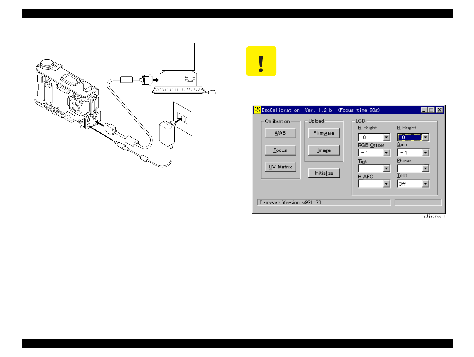
EPSON PhotoPC 800 Revision A
CAUTION
Error message “Camera is not connected” will be
„
displayed, when you try to activate the program without
To COM1 or COM2
serial port
Serial Cable
AC adapter
JEP-6
turning the power of the camera On.
When using the Color Viewer, turn on the switch and wait
„
for 30 minutes for aging to take place before using Color
Pure.
Figure 5-1. Setting-Up before adjustment
1. Turn off both Camera and PC.
2. Locate the port cover on the side of the camera. Press on the arrows and
slide the cover down to open it.
3. Line up the arrow on the cable connector with the notch on the camera’s
serial port. Insert the connector.
4. Locate a serial port on the back of your computer. You may have two serial
ports labeled COM1 and COM2, or the ports may be labeled with icons. If
you have two serial port available, use port1 to connect your camera.
5. Line up the serial connector on the cable with one of serial ports on your
computer, and insert the connector.
6. Turn on the camera and your computer system.
7. Insert the calibration software into the disc drive.
8. Double-click “DSCCalDi.EXE” in the disc and activate the program.
Adjustment Overview 77
Figure 5-2. Initial Screen of Adjustment Program
Page 78

EPSON PhotoPC 800 Revision A
5.2 Adjustment
5.2.1 Initialization Operation
This section explains initialization, which must be done before adjustment.
Unlike the previous models, even after initialization is performed, various
adjustment values are not cleared in PhotoPC-800. Only the image storage
area is cleared.
CAUTION
1. Complete the setting-up for adjustment. (See “Getting Ready for
Adjustment” on page -76)
2. Press “Initialize” button on the program. (Indication for confirmation
appears)
Perform initialization since an error may appear, if
uploading such as firmware is performed with full of
shooting data in the image area.
3. Select “Yes” and perform initialization. A few seconds later, the screen
below will appear.
Figure 5-4. Screen when completing the initialization
4. Mark • to indicate the camera resolution moves about for 20 seconds.
(Time varies according to the image data size at that time) Although mark
•
on the camera body moves slower than the timing of the ending
indication on the program, you can remove the AC adapter or serial
communication cable when you find the ending indication on the program.
5. Press “O.K” button on the screen.
Yes (Y)
No (N)
Figure 5-3. Screen when selecting initialization
Adjustment Adjustment 78
Page 79

EPSON PhotoPC 800 Revision A
5.2.2 Positions for measuring and adjusting on the
PW1 Board
When replacing the PW1 board, it is not necessary to perform this adjustment.
However, it is required to perform this if you replace any parts of PW1 board.
CL532
CL530
CL534
CL537
CL523
CL533
VR502
VR508
VR503
CL518
VR501
Q5008 (C)
VR506
Q5033-4
Q5029-3
VR507
CL512
PREPARATION
1. Connect CN104 on the CA2 board and CN502 on the PW1 board with
extension cord.
2. Open the barrier switch.
3. Set the view mode, and turn on the LCD.
4. Carry out initialization and display the through image on the LCD screen.
5.2.2.1 IC501 Oscillation Frequency Adjustment
SETTING
†
Measuring Point: CL512
† Measuring Equipment: Frequency counter
† ADJ.Location: VR501
† ADJ. Value: 200 ±1 kHz
† Dial switch: LCD shooting mode
ADJUSTMENT METHOD
1. Adjust with VR501 to 200 ±1 kHz
CL536
VR504
VR505
Figure 5-5. Positions for measuring and adjustment
Voltage adjustment is necessary to repair in the PW1
CAUTION
„
board and replace the parts.
Power voltage is set about +3.0 V.
„
Adjustment Adjustment 79
Page 80

EPSON PhotoPC 800 Revision A
5.2.2.2 IC502 Oscillation Frequency Adjustment
SETTING
†
Measuring Point: CL532 or Q5008 collector
† Measuring Equipment: Frequency counter
† ADJ.Location: VR502
† ADJ. Value: 400 ±1 kHz
† Dial switch: LCD shooting mode
ADJUSTMENT METHOD
1. Adjust with VR502 to 400 ±1 kHz
5.2.2.3 5.0V (D) Voltage Adjustment
SETTING
†
Measuring Point: CL518
† Measuring Equipment: Digital voltmeter
† ADJ.Location: VR505
† ADJ. Value: 5.10 ±0.05V
† Dial switch: LCD shooting mode
5.2.2.4 3.3V (D) A Voltage Adjustment
SETTING
†
Measuring Point: CL533 or CL534
† Measuring Equipment: Digital voltmeter
† ADJ.Location: VR503
† ADJ. Value: 3.30 ± 0.03 V
† Dial switch: LCD shooting mode
ADJUSTMENT METHOD
1. Adjust with VR503 to 3.30 ± 0.03 V
5.2.2.5 3.4V (D) B Voltage Adjustment
SETTING
†
Measuring Point: CL536 or CL537
† Measuring Equipment: Digital voltmeter
† ADJ.Location: VR504
† ADJ. Value: 3.41 ± 0.03 V
ADJUSTMENT METHOD
† Dial switch: LCD shooting mode
1. Adjust with VR505 to 5.10 ± 0.05 V
ADJUSTMENT METHOD
1. Adjust with VR504 to 3.41 ± 0.03 V
Adjustment Adjustment 80
Page 81

EPSON PhotoPC 800 Revision A
5.2.2.6 12.4V (L) Voltage Adjustment 1
SETTING
†
Measuring Point: CL523 or pin 3 of IC5029
† Measuring Equipment: Digital voltmeter
† ADJ.Location: VR507
† ADJ. Value: 12.40 ± 0.05 V
† Dial switch: Play mode
ADJUSTMENT METHOD
1. Adjust with VR507 to 12.4 ± 0.05 V
5.2.2.7 12.4V (L) Voltage Adjustment 2
SETTING
†
Measuring Point: CL523 or pin 3 of Q5029
† Measuring Equipment: Digital voltmeter
5.2.2.8 5.8V (L) Voltage Adjustment
SETTING
†
Measuring Point: CL530 or pin 4 of Q5033
† Measuring Equipment: Digital voltmeter
† ADJ.Location: VR508
† ADJ. Value: 5.80 ± 0.05 V
† Dial switch: LCD shooting mode
ADJUSTMENT METHOD
1. Adjust with VR507 to 5.80 ± 0.05 V
† ADJ.Location: VR506
† ADJ. Value: 12.40 ± 0.05 V
† Dial switch: LCD shooting mode
ADJUSTMENT METHOD
1. Set the view mode, and turn on the LCD
2. Adjust with VR506 to 12.4
± 0.05 V
Adjustment Adjustment 81
Page 82

EPSON PhotoPC 800 Revision A
5.2.3 Lens Adjustment
PREPARATION
Power switch: ON
Serial
cable
Camera
adj01
95
3cm
±
Simens Star
ADJUSTMENT METHOD
1. Set the siemens star chart 95cm ± 3cm so that it becomes center of the
screen.
2. Double-click on the DscCalDi122.
3. Click the Focus, and click the Yes.
Button for lens adjustment
Chart
Figure 5-6. Lens Adjustment
Figure 5-7. Button Location of Lens Adjustment Button
ADJUSTMENT CONDITION
†
More than A3 size siemens star chart
† Fluorescent light illumination with no flicker (incandescent light can not be
used)
4. Lens adjustment value will appear on the screen. Appropriate adjustment
value is
5. Click the OK.
±100.
† Illumination above the subject should be 400 lux ± 10%.
Adjustment Adjustment 82
Page 83

EPSON PhotoPC 800 Revision A
5.2.4 AWB Adjustment
Button for AWB adjustment
PREPARATION
†
Power switch: ON
Serial Cable
Figure 5-9. Button Location of AWB Adjustment Button
4. AWB adjustment values will appear on the screen.
† Appropriate Value Level
„ R: Around 213
adj02
Camera
0
18cm
±
Color Viewer
(5100K)
Figure 5-8. AWB Adjustment
„ G: 128 (fixed value)
ADJUSTMENT
„ B: Around 266 (Correction of difference of mechanism shutter)
† Error Condition
1. When setting the camera in place, set it to an angles so that nothing
appears in any part of the color viewer except the white section. (Do not
enter any light)
2. Double-click on the DscCalDi122.
3. Click the AWB, and click the Yes.
a0=65535, 65535, 65535, 1023 are indicated, when the sampling error
occurs.
5. Click the OK.
Adjustment Adjustment 83
Page 84

EPSON PhotoPC 800 Revision A
5.2.5 Color Matrix Adjustment
Button for Color Matrix Adjustment
PREPARATION
†
Power switch: ON
Serial Cable
15 ± 1cm
Camera
Color
Color Viewer
adj03
(5100K) and
Color Matrix
Figure 5-10. Color Matrix Adjustment
Figure 5-11. Button Location of Color Matrix Adjustment
5. Color matrix adjustment values will appear on the screen.
† Appropriate value level
„ UVMAT0-4: 0 - 255
† Error Condition
„ UVMAT0-4: All 1
ADJUSTMENT
† Iris failure
„ UVMAT0-4: All 2
1. Set the color adjustment chart to the color viewer. (Do not enter any light)
2. Set the siemens star chart so that it becomes center of the screen.
3. Double-click on the DscCalDi122.
4. Click the UV Matrix, and Click the Yes.
6. Click the OK.
Adjustment Adjustment 84
Page 85

EPSON PhotoPC 800 Revision A
CL158
CL161
CL157
CL159
5.2.6 CCD Defect Detect Adjustment
PREPARATION
†
Power switch: ON
† Lens Cover Switch:Leave it closed
ADJUSTMENT METHOD
1. Double-click on the DscCalDi122.
2. Click the “CCD Defect” from the pull down menu of Test, and the click the
“Yes”.
Test button
5.2.7 LCD Panel Adjustment
This adjustment should be performed when the CA2 board or is replaced or
IC171 on the CA2 board is replaced. Figure below shows measuring and
adjusting points on the A side of CA2 board.
Figure 5-13. Positions for measuring and adjusting
PREPARATION
†
Dial switch: PC connection mode
† LCD Type: LCD1 (default)
Figure 5-12. CCD Defect Detect Adjustment
3. After adjustment is done, if any failures are found, maximum 16 failures are
indicated by x and y coordinates.
Adjustment Adjustment 85
Page 86

EPSON PhotoPC 800 Revision A
5.2.8 LCD H AFC Adjustment
PREPARATION
†
Power switch: ON
ADJUSTING METHOD
1. Double-click on the DscCalDi122.
2. Select to “0” on the LCD “H AFC”
3. Apply the trigger at CL159, and adjust H AFC so that the time A from the
point where the pulse at CL161 rises until the position where the video
signal at CL159 starts in 2.9
CL161
CL159
± 0.2 µsec.
A
5.2.8.1 LCD RGB Offset Adjustment
ADJUSTMENT METHOD
Adjust LCD “RGB offset” so that the amplitude of the CL159 waveform is 6.8 V
± 0.3Vp-p.
0.3Vp-p
6.8
±
CL159 waveform
Figure 5-15. RGB Offset Adjustment
adj05
enlargement
A
CL161
CL159
adj04
Figure 5-14. LCD H AFC Adjustment
Adjustment Adjustment 86
Page 87

EPSON PhotoPC 800 Revision A
CAUTION
CL159 waveform
VG
VG
±
0.2V
CL157 waveform
adj07
5.2.8.2 LCD Gain Adjustment
ADJUSTING METHOD
Adjust LCD “Gain” so that the amplitude of the CL159 waveform is 4.2 ± 0.2Vpp.
CAUTION
LCD Gain Adjustment should be performed after LCD RGB
Offset adjustment is carried out. (“LCD RGB Offset
Adjustment” on page -86)
4.2±0.2Vp-p
5.2.8.3 LCD Blue Brightness Adjustment
ADJUSTING METHOD
Adjust LCD “B Bright” so that the amplitude of the CL157 waveform is ± 0.2V
with respect to the CL159 (VG) waveform(green).
LCD RGB Offset adjustment (“LCD RGB Offset Adjustment”
on page -86) and LCD Gain adjustment (“LCD Gain
Adjustment” on page -87) should always be carried out
before LCD Blue adjustment is performed.
Adjustment Adjustment 87
CL159 waveform
Figure 5-16. Gain Adjustment
adj06
Figure 5-17. Blue Brightness Adjustment
Page 88

EPSON PhotoPC 800 Revision A
5.2.8.4 LCD Red Brightness Adjustment
ADJUSTING METHOD
Adjust LCD “R Bright” so that the amplitude of the CL158 waveform is ± 0.2V
with respect to the CL159 (VG) waveform.
CAUTION
LCD RGB Offset adjustment (“LCD RGB Offset Adjustment”
on page -86) and LCD Gain adjustment (“LCD Gain
Adjustment” on page -87) should always be carried out
before LCD Red Brightness Adjustment is performed.
VG
CL159 waveform
5.2.9 Uploading the Firmware
1. Complete the setting-up for adjustment. (“Getting Ready for Adjustment”
on page -76)
2. Store the Firmware which is provided from SEIKO EPSON to the
appropriate hard disk. (Firmware is usually bin. file and compressed)
3. Select “Firmware” on the program.
4. File Open Dialog will open, since the location were the file is stored is
appointed.
Open
Look in:
VG
0.2V
±
File Name (N):
Files of Type (T):
Open
Cancel
Figure 5-19. Program screen for Firmware Upload
CL158 waveform
adj08
5. Select the new Firmware and press “Open”.
Figure 5-18. Red Brightness Adjustment
Adjustment Adjustment 88
Page 89

EPSON PhotoPC 800 Revision A
6. LED located on the front side of the camera blinks for 20 seconds to
indicate that the uploading is being performed correctly. (If SY1 board is
removed, LED does not blink)
If the power supply stops or the serial communication
CAUTION
7. When the uploading gets close to the end, the camera beeps one time and
lets you know that the operation moved from reading to writing to Flash
Memory.
„
cable comes off during the uploading of Firmware, this
may lead to destroy the Flash Memory. Therefore, do not
perform other operation until “Complete” is indicated.
In the firmware, there are 2 types of specification; NTSC or
„
PAL. Do not upload the firmware for PAL to NTSC, or its
opposite. (However, there is a protection function on the
program)
When the uploading of Firmware is performed, Hyper
„
function, Direct Print function and Print mark function are
erased at the same time. Therefore, after completing the
upload, these 3 functions have to re-install by using the
Uploader, which should be included in the same package.
CAUTION
8. After one or two seconds later, when writing operation is completed,
beeping sound is emitted again. Then, a message “Update Firmware:
Complete” is indicated on the screen.
9. Press OK button.
Be careful not to take the first beep sound (indication of the
operational change from reading to writing to the Flash
Memory) as the ending sound of operation.
When the operation is completed, the second beep sound is
emitted and a message “Complete” is indicated on the
screen. Make sure that a message “Complete” is indicated
on the screen before getting off the program.
Adjustment Adjustment 89
Page 90

MAINTENANCE
&+$37(5
9
Page 91

EPSON PhotoPC 800 Revision A
6.1 Preventive Maintenance
PhotoPC-800 does not require specific maintenance such as lubrication or
cleaning on a regular basis. However, it is necessary to perform cleaning
according to its necessity if any dirt or fingerprints are found attached on the
parts during the repair service. The table below lists check items and cleaning
points when the repair service is completed.
6.1.1 Check Points
Refer to the table6-1 and perform proper service referring to Chapter 4
Disassembly and Assembly, if you find any stain or defective parts. Dust or
finger prints can be removed by touching it several times with Scotch tape.
Table 6-1. Items to check
No. Check Points Check
Is in and out of lens viewfinder free from the finger
1
prints or dirt? Also, Aren’t any power supply cable
seen out of viewfinder?
Does the di al(rotary) switch move smoothly and
2
feeling to click ?
Do you see any dirt or dust in and out sides of flash
3
window?
Are the glass surface of the LCD panel on the SY1
4
board and in and out sides of protection board of the
rear cabinet free from the finger prints or dirt?
5 Is the lens surface free from the fingerprints or dust? † OK † NG
Is the glass surface of LCD monitor free from the
6
finger prints or dust?
7 Does the battery cover close or open normally? † OK † NG
Can the compact flash memory card be inserted
8
correctly?
Is the rubber cover, which covers variou s conn ectors
9
and serial connector installed at the rear cabinet
correctly?
† OK † NG
† OK † NG
† OK † NG
† OK † NG
† OK † NG
† OK † NG
† OK † NG
10 Does the each panel switch work normally? † OK † NG
11 Is the exterior clean? † OK † NG
Maintenance Preventive Maintenance 91
Page 92

APPENDIX
&+$37(5
:
Page 93

EPSON PhotoPC 800 Revision A
7.1 Connections among Boards
Following pages show the connections among boards.
Appendix Connections among Boards 93
Page 94

Page 95

EPSON PhotoPC 800 Revision A
7.2 Component Layoust of Circuit Boards
Following pages show the component layout of each circuit board.
† CA1 Circuit Board
† CA2 Circuit Board
† SY 1 Circuit Board
† PW1 Circuit Board
Appendix Component Layoust of Circuit Boards 94
Page 96

ca1_pcb
Page 97

ca2_pcb
Page 98

sy1_pcb
Page 99

pw1_pcb
Page 100

EPSON PhotoPC 800 Revision A
7.3 Circuit Shematics
† CA1 Circuit
† CA2 Circuit
„ NTSC
„ PAL
† SY1 Circuit
† PW1 Circuit
Appendix Circuit Shematics 99
 Loading...