

Page 1

®
6HUYLFH 0DQXDO
6HUYLFH 0DQXDO
6HUYLFH 0DQXDO6HUYLFH 0DQXDO
Color Digital Camera
EPSON PhotoPC-750Z
SEDC98002
Page 2

EPSON PhotoPC-750Z Revision A
CAUTION
PRECAUTIONS
There are cautionary notes throughout the text to help you avoid personal injury or equipment damage.
W ARNING
Signals a precaution which, if ignored, could result
in serious or fatal personal injury. Great caution
should be exercised in performing procedures
preceded by a WARNING heading.
Always observe the measures listed below when performing repair or maintenance procedures.
Signals a precaution which, if ignored, could result
in damage to equipment.
WARNING
1. Always disconnect the product from both the power source and host computer before performing any maintenance or repair procedure.
2. No work should be performed on the unit by persons unfamiliar with basic safety measures dictated for all electronics technicians in their line of
work.
3. In performing testing described in this manual, do not connect the unit to a power source until instructed to do so. When the power supply cable
must be connected, use extreme caution in working on the power supply and other electronic components.
CAUTION
1. Repairs on EPSON products should be performed only by an EPSON-certified repair technician.
2. Make certain that the source voltage is the same as the rated voltage liste d on the seri al number/rati ng plate. If the EPSON product has a pr imary
AC rating different from the available power source, do not connect it to the power source.
3. Always verify that the EPSON product has been disconnected from the power source before removing or replacing printed circuit boards and/or
individual chips.
4. To protect sensitive microprocessors and circuitry, use static discharge equipment, such as anti-static wrist straps, when accessing inter nal
components.
5. Replace malfunctioning components only with those components recommended by the manufacturer; i ntroduction of second-source I Cs or other
nonapproved components may damage the product and void any applicable EPSON warranty.
2
Page 3

EPSON PhotoPC-750Z Revision A
Revision Status
Revision Issued Date Description
Rev.A February 16, 1999 First Release
3
Page 4

EPSON PhotoPC-750Z Revision A
Table of Contents
Product Description
Features ... ....... ...... ....... ...... ...... ....... ............................................. ....... ...... ..... 7
Product Description................................................................................... 9
Control Panel........................................................................................... 16
Control Buttons........................................................................................ 18
Capturing Mode Indication ...................................................................... 19
Operation Specification . ...... ....... ...... ....... ...... ....... ...... ............................. 19
Cable Specification.................................................................................. 21
Options.................................................................................................... 22
Environmental Conditions ....................................................................... 22
Power...................................................................................................... 22
Safety and others .................................................................................... 22
Operating principles
Board Component ........................................................................................ 24
Out line of Operating Principles............................................................... 25
CA1 Board............................................................................................... 25
CA2 board............................................................................................... 26
ST1 Board............................................................................................... 26
SY1 Board............................................................................................... 27
TB1 Board............................................................................................... 28
TB2 Board............................................................................................... 28
Picture is blurry or out of focus................................................................ 36
Disassembly and Assembly
Overview ...................................................................................................... 38
Precautions ............................................................................................. 38
Tools ....................................................................................................... 39
Screws .................................................................................................... 39
Disassembly and Assembly .................................................................... 40
Cabinet Parts Removal ........................................................................... 41
SY1 Board, TB1 Board and FPC Unit Removal...................................... 42
CA1 Board Removal ............................................................................... 43
DEC Lens, PW1, CA2 Board, Cover Connector, Lens Unit and Holder Lens Removal
43
Assembly................................................................................................. 45
Installing parts to the (front) Cabinet....................................................... 45
Installing parts to the CA1 Board ............................................................ 46
Setting-Up the CA2 Board..................................... ....... ...... ..................... 48
ST1 Board Setting-Up............................................................................. 49
ST1 Board Setting-Up (2)........................................................................ 50
CA2 Board Setting-Up (2) ....................................................................... 50
Installing Parts to the CA1 Board (2)....................................................... 51
Connecting Boards.................................................................................. 51
Installing the Cabinets............................................................................. 56
Troubleshooting
Overview....................................................................................................... 30
The Camera has no power...................................................................... 31
LED red light blinks / No green light........................................................ 33
Shutter does not work ............................................................................. 33
Image is taken out of cross mark in the viewfinder (Not using LCD monitor)
34
Nothing appears on the Camera and Computer screen (All black)......... 34
Unable to transfer the image data to PC................................................. 35
No Images on the LCD (All black)........................................................... 35
Unable to use the Optional Compact Flash............................................. 36
Adjustment
Overview ...................................................................................................... 60
Getting Ready for Adjustment................................................................. 61
Initialization ............................................................................................. 63
Flange-back Adjustment ........................................................................ 64
AWB5100K Adjustment...................... ...... ....... ...... ....... ...... ..................... 65
Color Matrix Adjustment.......................................................................... 66
CCD Defect Detect Adjustment............................................................... 67
Uploading the Firmware.......................................................................... 67
4
Page 5

EPSON PhotoPC-750Z Revision A
Maintenance
Preventive Maintenance............................................................................... 71
Check Points ........................................................................................... 71
Appendix
Circuit Shematics.......................................................................................... 73
5
Page 6

PRODUCT DESCRIPTION
&+$37(5
4
Page 7

EPSON PhotoPC-750Z Revision A
1.1 Features
PhotoPC-750Z is a compact and high performance digital still camera
equipped with 1.3 million pixels high resolution color CCD and built-in
Color LCD view monitor. Following shows overview and characterist ics
of this product.
[Intended User]
† Professional Users
† Individual Users (Advanced or Intermediate Users)
† For Business Users (For making reports with pictures)
[Recommended Usage]
† For making Home Pages for Web
† For making proceedings with pictures
† For making post cards with pictures
† For making calendar with pictures
[Overview of product]
† 2-way lighting source LCD monitor
2 inches low temperature poly-silicon LCD monit or lit up by sunlight
or a fluorenscent back light. Using sunlight, it leads the power
saving.
† Available selection either skylight feature in bright sunlight /
Backlight in the indoor
† Energy Saving type LCD monitor. (unlike the surface type in the
previous models, 1 line fluorenscent type is applied)
† HyPicT mode
Providing a high quality image based on an EPSON original picture
enhancement technology. Super high quality image by high image
correction skill, equivalent to 2000K pixels CCD.
† Quick Shooti ng Mode:
Taking photos at intervals of under 2 seconds
† Variet y of Shooting Mode:
More available shooting modes than previous models.
† Direct Printing:
A4 direct printing just by connecting the camera and print e r without
using PC.
† High resolution color CCD applied
† 1.3 million pixels CCD sensor. 1/2.7 inches hig hly sensitive CCD
with complementary color filters.
† Optical 3x powered zooming
† Equivalent to 35 mm
(Wide angle lens
<Actual range: 34mm
∼105mm focal length on a 35mm camera.
∼ Telephoto lens: 35 mm film camera equivalent)
∼ 102 mm>
Product Description Features 7
Page 8

EPSON PhotoPC-750Z Revision A
[Product Characteristics]
† High resolution:
4 x VGA (1280 x 960 pixels, 24-bit Color)
† CCD Sensor:
1/2.7 inch color area CCD sensor (1.3M pixels)
† Optical Lens:
Equivalent to 35mm
(Wide angle lens
<Actual range, 34mm
∼ 105mm lens, Optical 3 x powered zooming
∼ Telephoto lens: 35 mm film camera equivalent)
∼ 102 mm>
† Color LCD Monitor:
2-inch 2-way lighting source color TFT LCD monitor.
(Low -temperature Polycrystlline Silicon TFT active matrix)
† Focus Adjustment:
Automatic Focus (TTL type AI Auto Focus)
† Exposure Control:
Program auto exposure (Auto measure by CCD, but manual
adjustment is also available)
† White Balance:
Auto white balance/ Fixed mode(sun light) / User defined mode
(customize)
† Built-in RAM:
2 D-RAMs (4M) for temporal storage of the image data, and inpu t or
output of the image data at View mode.
† Buil t- in Memory (I nternal Memory):
4MB(for recording images, firm ware and optional programs), but
more than 2 M with program area will be consumed when installing
the optional direct print function.
† Image file format:
Based on JPEG (3 modes; Super fine, Fine, Standard)
† Image size:
1280 x 960 (Super fine/Fine), 640 x 480(Standard), 1280 x 480
(Panorama), 1600 x 1200 (HyPict)
† Built-in Flash:
Auto, Flash Off, Forced Flash
† Optical Viewfinder:
Optical real image view finder interlocked with zooming
† Visual effect:
Digital 2x zoom, Panorama, Continuous shooting, Black&White
† Power source:
Four AA-size (Alkaline, Ni-Cd, Lithium, Ni-MH)
† PC I/F:
High speed serial interface (Auto/19200/38400/57600/115200/
230400 bps)
† Video Output:
NTSC video output function (Japan, US)
PAL video output function (EU)
† Direct Printing: Available with following printers;
Stylus Photo, Stylus Photo 700, Stylus Pho to 750, St ylus Phot o EX,
Stylus Photo 1200.
† Options:
See the table on next page.
† External Memory:
Compact Flash memory cards are available.
Product Description Features 8
Page 9

EPSON PhotoPC-750Z Revision A
Table below shows the optional items of PhotoPC-750Z.
Table 1-1. Options
No. Name Code No.
1
2
3 NI-MH Rechargeable Batteries (4) B81811*
4 Compact Flash Cards
5 PCMCIA adapter B867041
EPSON AC Adapter
(input:100V, output:DC7V-2A)
Power Pack
(Ni-MH Charger + Ni-MH
rechargeable batteries)
B86703*
B81812*
4MB: B808311
15MB:B808301
NOTE:The asterisk in the code No. is a substitute for the last di git,
which varies by country.
1.1.1 Product Description
† Data Type: JEPG (Based on JFIF)
† Thumb nail Image: 160 x 120 pixel
† Image size: 1600 x 1200 pixel (HyPict)
1600 x 600 pixel (HyPict Panorama)
1280 x 960 pixel (Super fine, Fine)
1280 x 480 pixel (Panorama Super Fine, Panorama
Fine)
640 x 480 pixel (Standard)
† Color: 24-bit Full Color/Monochrome
NOTE: In case of HyPict, it is necessary to upload the included
program.
[Optical]
† CCD: 1/2.7 color area CCD (1300K pixels)
Complementary Filter
† Total Pixel: 1343 x 972
† Effective pixel: 1290 x 966
† Actually used pixel:1280 x 960
NOTE: Effective pixel - Actually used pixel = Opti cal black on the
CCD.
† Lens: f=5.2 ∼ 15.6 mm (equivalent to 35mm to
105mm lens on a 35 mm camera)
† Brightness: F2.8 (at f=5.2mm)
∼ F4.7 (at f=15.6 mm)
† Lens Construction: 7 elements in 7 groups
† Focus: F2.8 (opening) / F8
Product Description Features 9
Page 10

EPSON PhotoPC-750Z Revision A
† Viewfinder: Optical real image view finder interlocked with
zooming (View range over 80%)
Correction frame for 80 cm distance from an object
with AF target mark is available.
Cross (+) mark in the finder.
† Sensitivity: Equivalent to ISO 90 (at Standard)
ISO 180/360 high sensitivity is availabl e
† White Balance: TTL type Auto White Balance (rely on AWB
adjustment circuit) Fixed mode or User defined
(customize) mode is available.
† Flash: Aut omatic luminance control flash;
Forced flush, Flash off, Slow Synchro Flash (for
taking pictures at night or in dark place) mode.
Full Auto TTL
† Exposure Time: Program auto exposure by CCD
† Flash Range: 0.2m
∼2.4m for all modes except for wide angle and
zoom (Auto
→Forced on →Forced Off by operation
button)
NOTE:When shooting at macro mode, exposure over will occur if
flash is emitted in 0.2 m (maximum range). In order to avoid
this, use tripod without using flash, avoiding hand vibration.
[Shooting Mode]
† LED Indication:TTL Image Playback (Playback rate 1/30 second)
† Self-Timer: 10-second timer (Slow blinking for 8 seconds,
fast blinking for 2 seconds)
† Macro Mode: Shooting range 20cm
∼ 80cm
† Quick Shooting Mode: In this mode, processing time from one
shooting to the second shooting is shortened by saving the taken
images in the built-in D-RAM. Usually, the image data i n the D-RAM
is processed by
γ correction and in the AWB correction circuit, then
stored in the built-in or external memory. However, in this mode,
these process are not performed but uses the available area of DRM(2M out of 4M) and save the processing time.
*220 KB (Super fine Panorama): 2 seconds
*640 KB (HyPict): 5.6 seconds
Table 1-2. Flash Range
Sensitivity setting Wide angle Zoom
Std. (ISO 90) 0.8
Med. (ISO 180) 0.8 ∼ 3.9m 0.8 ∼ 2.2m
High (ISO 360) 0.8 ∼ 5.6m 0.8 ∼ 3.2m
2.8m 0.8 ∼ 1.6m
∼
NOTE:Maximum available shooting in this mode is up to 20
pictures.
† Continuous Shooting Mode: 2 pictures per second
NOTE:1.Need to press the shutter continuously when using this
function.
NOTE:When shooting a object with bad contrast or with low
illuminance, auto focus may not work correctly. Auto focus
does not work for the object which require the flash emiss ion
forcefully. In this ca se, take about 1.5 m between the camera
and the object forcefully for shooting.
2.Single push results only one picture .
3.Beep sound will be heard every shooting.
4.Flash is forced to be Off, since the necessary charging
time can not keep up with the shooting speed.
5.Available up to 16 pictures at VGA image.
Product Description Features 10
Page 11

EPSON PhotoPC-750Z Revision A
† Digital Zoom: 2 x digital zoom without relying on the optical zoom.
Therefore, digital zoom + optical zoom = 6 x zoom is
available.
[Memory]
† Buil t- in RAM: D-RAM 2MB x 2 (Total 4M)
† Built-inROM: 4 MB (Recorded image + program + included
utility)
† External Memory: Compact Flash Card
† PC-DOS for m at : 512B/Sect
[Indication Function and others]
† LCD Monit or: 2 inch TFT color LCD monitor with dual lightin g
system, electric backlight and skyli ght
(110K pixels: 512 x 218 pixels)
† View rate at shooting:More than 90%
† Playback view range: 100%
5)Indicates fixed white balance mode
6)Indicates High sensitivity mode
7)Indicates continuous shooting mode
8)Indicates self-timer mode
9)Indicates Flash mode
10)Indicates Low battery
† LED next to VF: Green/Orange/Red-blinking/Red
† Timer: Built-in Timer IC (Year/Month/Date, Time/Minute/
Second)
NOTE:However, Timer IC operates when the battery is installed.
When the batteries are exchanged, about 30 minu tes wi ll be
keep counting the time until the electricity in the capacitor
located under SY1 board goes out completely.
† Power saving function: Effective only at battery mode. Save or
Norm.
*Save: Power off right after shooting.
*Norm: Power off 30 seconds after shooting.
NOTE:No power saving function when using the AC adapter.
† Beep soun d: Available (On/Off setting: However, beeping
sound is forced to be ON at continuous shooting,
everytime the picture is taken.)
† Self- Timer Indication: Timer for 10 seconds
† Control LCD Panel:
1)Indicates the number of available pictures (3 digits)
2)Indicates current exposure value when the
Function button is pressed.
3)Indicates the setting of image quality mode
(includes black and white, HyPict mode)
4)Indicates installation of Memory Card
Product Description Features 11
Page 12

EPSON PhotoPC-750Z Revision A
[UI Menu (View Mode Menu)]
† Conditions: Continuous / quick shooting mode
White balance (Auto/Fixed/ Customize)
Exposure value (Auto/ Adjust <9-step>)
Sensitivity (St d ./Med./High)
Flash (Standard, Slow-synchroniz ation strobe)
† Settings: Date and time setting (year/month/day/time),
indicating order of year, month and day setting.
Beep sound condition (On/Off)
Brightness of color LCD display (7 levels)
Power saving mode (Save/ Norm)
† Information: Super imposing information on an image (On/Off)
[UI Menu (Playback Mode Menu)]
† Settings: Date and time setting (year/month/day/time),
indicating order of year, month and day setting.
Beep sound condition (On/Off)
Brightness of color LCD display (7 levels)
Power saving mode (Save/ Norm)
† Slide Show: Automatic playback / Pausing function
† Software: Optional software addition / erasing /execution
Direct printing
† Language: English, Japanese, French, German, Spanish,
Italian, Portuguese (PAL model)
English, Japanese (NTSC model)
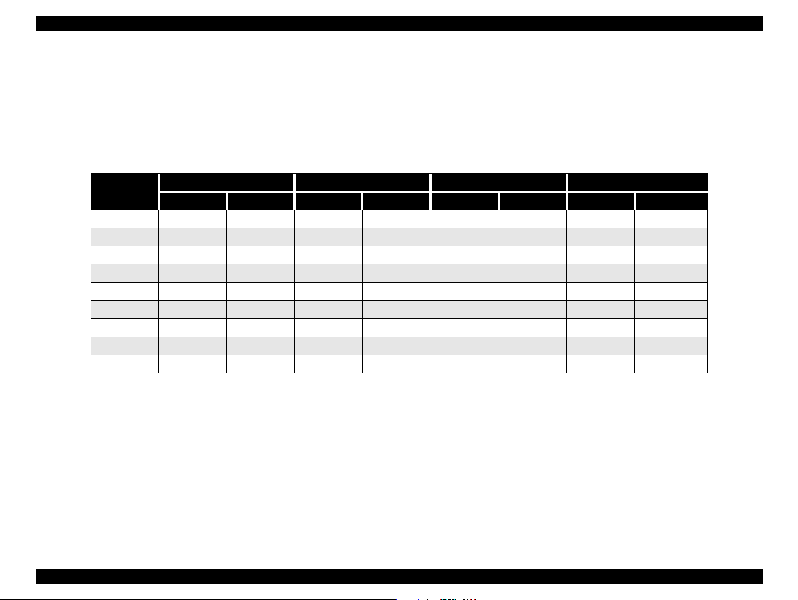
[Processing Time]
Table 1-3. Processing Time
Quality and
indications
Standard
Fine
Super-fine
•
••
•••
Capturing a
picture
(normal)
about 2 sec about 1 sec.) about 2.5 sec.
about 4.5 sec about 1.5 sec. about 5 sec.
about 6.5 sec about 2 sec. about 6 sec.
Interval time for the
next shot (quick
shooting)
Playback
NOTE:Use the values above as reference. Values above may vary
more or less because of the slight dispersion of internal
memory or circuit.
† In formation: Information about numbers of taken pictures,
remaining shots and date and time of capturing.
Indication of information (On/Off)
† Playback mode: Single picture display / 9 multiple pictures display
† Magnification: 2 x expansion and scroll functions are available.
† Photo Co ntrol: Erase: Single/All
Lock: Select/ All/Unlock
Image: Indicate Information
Copy: from internal memory to CF card/ Vice versa
Formatting CF card
Product Description Features 12
Page 13

EPSON PhotoPC-750Z Revision A
CAUTION
Table 1-4. Average storage capacity
NTSC model PAL model
Standard
(continuous shooting)
Fine
Super fine
HyPict
••
•
•••
H 3 2
•••
35 32
10 9
54
NOTE:1:Figures shown above represent storage capacity when
optional program are not installed in the camera’s internal
memory. If you remove the Direct Print program from the
camera, the storage capacity will increase and you can take
more pictures.
2:The number of pictures you can take depends on the
complexity of each photo, even if the image quality is the
same for all the photos.
[Reference for storage capacity wit h comp act flash card]
Table 1-5. Storage Capacity with Compact Flash Card
2: Figures shown above represent stroage capacity when there is no
image data in the internal memory and no opti onal sof tware is instal le d.
If other file is stored in the memory, available storage capacity
decreases according to the file volume.
[Power]
† Batter ies: 4 AA alkaline (lithium, Ni-Cd, Ni-MH batteries)
† Converter:AC-DC(7V) converter
Table 1-6. Battery Life
Alkaline Batteries
Shooting Mode Power Save Mode Normal Mode
View Mode (LCD on) 80 pictures available 40 pictures available
Finder mode (LCD off) more than 800 pictures available
Playback (LCD on) about 90 min.
NOTE:Measurement conditions: Save mode on. Strobe once in two
shots. 1 min. taking interval.
Selected
Mode
Standard
Fine
Super fine
Indicated
Marks
•
••
•••
4MB 10MB 15MB 20MB 48MB
60 158 227 304 365
19 20 72 97 116
9 25364959
NOTE:1: The maximum amount of pictures stored in the memory
card is 999.
Product Description Features 13
Although AA size MN (manganese) batteries can work
first for a while, it is not admitted in the specification
because its battery life allows only to take a few
pictures.
Page 14

EPSON PhotoPC-750Z Revision A
[Physical Dimensions]
† Width: 137.5mm
† Height: 76.4mm
† Depth: 61.8mm
† Weight: 310g (without batteries and strap)
† Tripod socket is available for installing the tripod
[Interface connectors and others]
† Video output: NTSC (NTSC model) or PAL (PAL model) video
output
W ARNING
Use only the AC adapter designed for the PhotoPC-
750Z. Since using any other adapter could keep
charging the batteries without pr oper operation of AC
Jack, it is prohibited to use other adapter.
† Inlet for DC power supply: DC power is supplied from AC adapter
(7V).
† Serial Interface: RS-422, 423 serial port (mini DIN 8 pins
terminals).
(Max. 230 k bps is available only on a PC
supporting this speed. In case of direct
printing, 900kbps or 1.8Mbps
synchronous transmission is available)
† Compact fl ash card slot: Compact flash type 1 card interface.
Product Description Features 14
Page 15
EPSON PhotoPC-750Z Revision A
[Serial Interfa c e ]
The serial interface should be announced as EPSON original
specifications for connecting to a PC/MAC, a pri n ter or a modem, and
the specifications are not open t o the public. Connect ing a PC/MAC. the
interface is compatible with RS-232C. A PC/MAC is required to support
19.2 kbps transmission rates at the minimum.
Table 1-7. Signal Name for Serial Communication Interface
Camera to PC to printer to modem
Pin assign. Circuits I/O Circuits I/O Circuits I/O Circuits I/O
1 HSKo O prCTS O HSKo O
2 HSKi I -- prSCK I HSKi I
3 TXD- O host RD O TXD- O TXD- O
4 GND GND GND GND
5 RXD- I host SD I RXD- I RXD- I
6 TXD+ O TXD+ O TXD+ O
7 GPi I prDTR I GPi I
8 RXD+ I -- RXD+ I RXD+ I
SHELL shell
Product Description Features 15
Page 16
EPSON PhotoPC-750Z Revision A
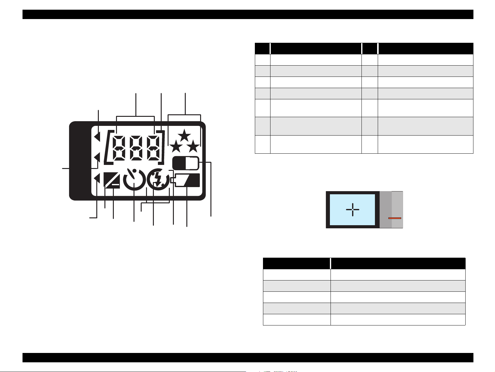
1.1.2 Control Panel
The figure below shows all indications on the LCD panel and table1-8
shows meaning of each mark.
1
2 3
14
WB
H
IS O
13
H
Cnt
12
+
11
10
9
8
7
B
W
A
4
6
5
Table 1-8. LCD panel
No. Display Meaning No. Display Meaning
1 Remaining shots number 8 Strobe off mode indicator
2 CF card insertion marker 9 Self-timer conditions indicator
3 Image quality indica tors 10 Exposure value decreasing indic at or
4 Monochrome mode indicator 11 Exposure value increasing indicator
5 Caution mark for batteries’ level 12
Automatic strobe (flash) mode
6
indicator
Coercive strobe (Forced flash)
7
mode indicator
Figure and table below show the indicati on of LED (st atus light ) besid es
Viewfinder.
Continuous or quick shooting mode
indicator
13 High sensitivity mode indicator
14 Manual white balance
Figure 1-1. LCD Panel Indication
LED (Status Light) Indication meaning
Off No power supply for camera (Power switch is off)
Green light On Power is On, Ready for shooting.
Orange light On Half-stroke shutter condition (AF locked)
Red light blink Image processing or preparing for shooting ready.
Red light On Memory is full (unable to shoot), Camera is broken.
Product Description Features 16
Table 1-9. LED (Status light)
Page 17

EPSON PhotoPC-750Z Revision A
CAUTION
When the camera is broken, sometimes error code is
indicated on the LCD. Table below shows the meaning
of the error code. However, since these error codes
are used in the developing stage and not reliable to
find out specific malfunction parts correctly.
Therefore, use this table as reference but find out
malfunction parts correctly by referring to Chapter 3.
Table 1-10. Error Code List
Error Code Indication Meaning
30s (such as 31, 32,..) Read/Write Error to CF card (includes downloading to PC)
80s (such as 81, 82,83..) Read/Write Error to CF card (except above)
60s Read/Write Error to internal Flash
90s Data write error to the external memory
100s Data write error to internal Flash
254s Access error to the incorrect address
Corresponding Ch circuit does not get activated, even
0
after 4-bit CPU on the SY1 board ouputs Wake-up signal
to the PW1.
Product Description Features 17
Page 18
EPSON PhotoPC-750Z Revision A
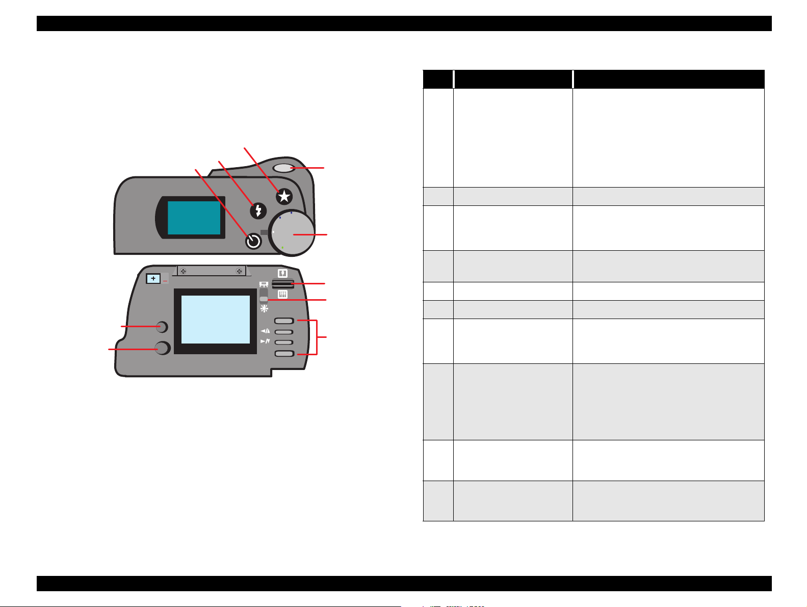
1.1.3 Control Buttons
Figure below shows layout of buttons and switches ,and table shows
function of each button.
3
4
10
5
WB
IS O
H
Cnt
Mode
9
Function
EPSO N
Figure 1-2. Switch Location
ESC
SEL.
Off
On
View
Play
2
1
6
7
8
Table 1-11. Meaning of buttons
No. Name of button Meanings and functions
• Off: Power off state.
• On: Mode for taking pictures with a view
finder. (pushing out the lens cylinder)
1 Rotary Switch
2 Shutter 2 stoke shutter button (half/full stroke)
3 Image Quality (Resolution)
4 Strobe (flash)
5 Self-timer Self-timer setting button
6 Zoom Zooming switch.
7 Back Light
8 Menu Buttons
9MODE
• View: Mode for taking pictures with a color
LCD monitor.
• Play: Playback mode of captured pictures
and the last picture will be shown first. (the
lens cylinder is still collapsed)
Image quality selection button
• Color: Standard, Fine, Superfine, HyPict
• Monochrome: Fine, Super fine, HyPict
Strobe mode selection button
(Auto
Forced On→Forced Off)
→
Save energy by;
Setting top: for shooting indoor, or
Setting down: for shooting outside
• ESC.:Exit from menu.
• Selecting function button (1): Move toward
left of upper side.
• Selecting function button (2): Move toward
right or lower side.
• SEL.:Execution function button.
Mode selection button.
(Standard
zooming
Panorama→Digital
→
Macro-photography mode)
→
Providing additional functions with pressing
10 FUNC.
other buttons. (for quick shooting, setting
exposure)
Product Description Features 18
Page 19
EPSON PhotoPC-750Z Revision A
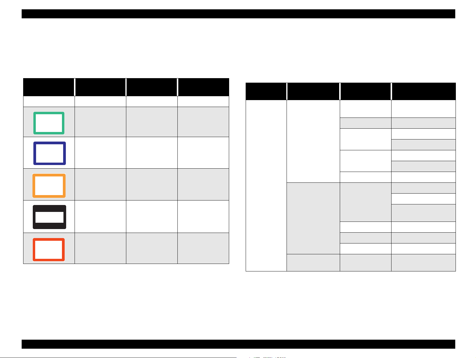
1.1.4 Capturing Mode Indication
There are several color frame indicators showing a current capturing
mode on the LCD monitor in the VIEW mode.
Table 1-12. Frame indication
Frame Indicator Frame Color Mode
Nothing Nothing Standard ---
Green Macro
Blue Monochrome
Orange Digital 2 x zooming
Upper and lower
fields are veiled by
black bands
Panorama
Characters and
indication period
MACRO
a few seconds
MONOCHROME
a few seconds
ZOOM
a few seconds
PANORAMA
a few seconds
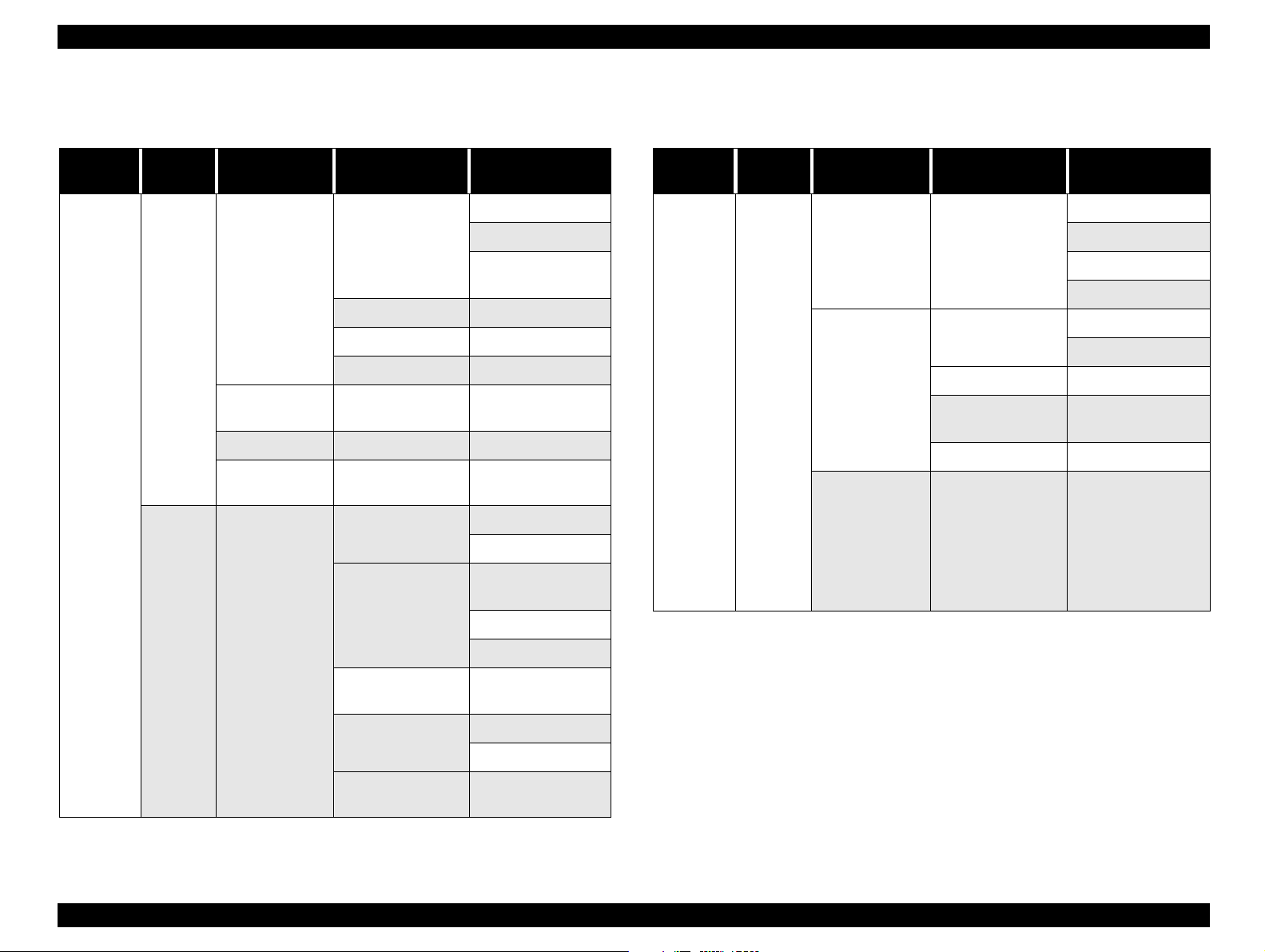
1.1.5 Operation Specification
Table below shows each operation menu.
† View Mode
Table 1-13. Operation Menu at View Mode
Camera Mode
View Mode
Menu Items in
View Mode
Capturing(shooting)
mode setting
Configuration
Setting
Item Name Function
Continuous/Quick
shooting
Auto/Manual Auto/Manual
White Balance
Exposure
Adjustment
Sensitivity Standard/Medium/High
Date and Time
Beep On/Off
Off/Continuous/Quick
Auto/Fixed/Custom
Customizing
Auto/Adjust.
Adjustment
Year/Month/date
Hours/ Minutes
Y.M.D / M.D.Y /D.M.Y
order
Power saving Save/Normal
Red
Continuous
shooting
CONTINUOUS
a few seconds
Information
indication
Luminance of LCD 5 levels
Display / Non
display
---
Product Description Features 19
Page 20
EPSON PhotoPC-750Z Revision A
† Playback Mode
Table 1-14. Operation Menu at Playback Table 1-15. Operation Menu at Playback
Camera
Mode
Playback
Screen
First
screen
Menu Items in
View Mode
Configuration
Setting
Information
indication
Playback mo de Single / Multiple --2 x
magnification
Item Name Function
Year/Month/date
Date and Time
Beep On/Off
Power saving Save/Normal
Luminance of LCD 5 levels
display / Non
display
9 areas can be
selected.
Erase
Lock
Hours/ Minutes
Y.M.D / M.D.Y /
D.M.Y order
---
---
Select and Erase
Erase All
Select and Lock/
Unlock
Lock All
Camera
Mode
Playback
Screen
Second
screen
Menu Items in
View Mode
Slide show Select
Optional
software
Language
Item Name Function
Addition /Delete
HyPict ---
Direct printing
Others
English/Japanese/
French/German/
Spanish/Italian/
Portuguese (PAL
mode)
English/Japanese
(NTSC)
Pause/ Continue
Forward
Backward
Stop
Addition
Delete
Go to an optional
menu
---
Second
Screen
Editing
Memory
information
Copy
Format
Unlock All
---
Camera to CF card
CF card to camera
Erase data in the
external memory
Product Description Features 20
Page 21
EPSON PhotoPC-750Z Revision A
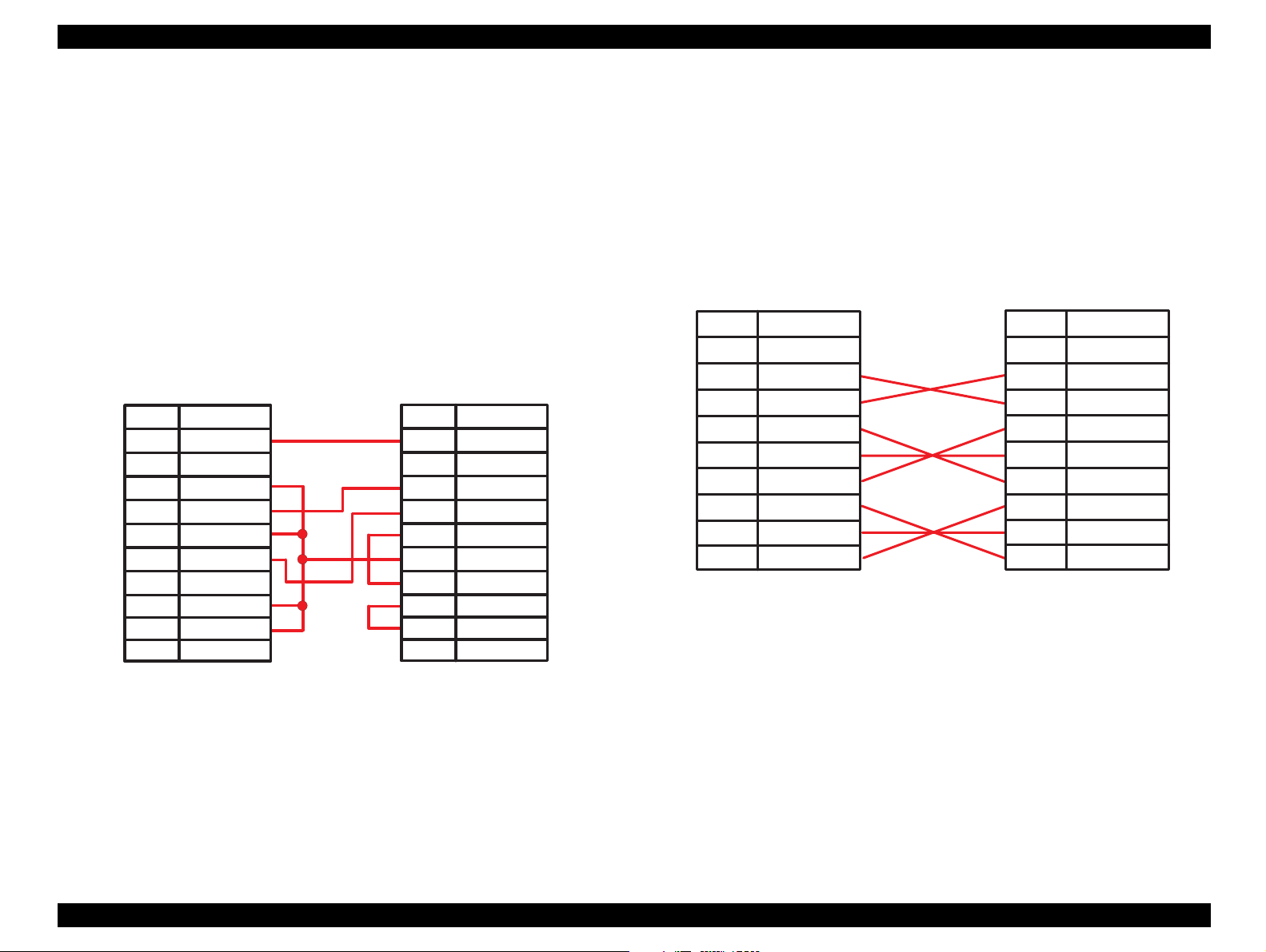
1.1.6 Cable Specification
Figure1-4 and 1-5 show cable connection diagram for DOS. V and
MAC. individually.
[DOS/V Cable]
† Cable Length: 1.5m
† Connector Type:
„ Camera side: 8 pins mini-DIN (male)
„ PC side: 9 pins DSUB (female)
Cam era PC
Pin No.
1
2
3
4
5
6
7
8
S ignal
shell
GND
----
host R D
GND
host SD
GND
GND
----
Pin No.
1
2
3
4
5
6
7
8
9
S ignal
shell
host C D
host R D
host SD
host D TR
GND
host D S R
host R TS
host C TS
RI
[MAC. Cable/Direct printing cable]
† Cable Length: 1.5m
† Connector Type:
„ Camera side: 8 pins mini-DIN (male)
„ PC side: 8 pins mini-DIN (male)
Cam era
Pin No.
S ignal
shell
1
2
3
4
5
6
7
8
HSKo
HSKi
TxD -
GND
RxD-
TxD +
GPi
RxD+
Figure 1-4. Cable Connection for MAC/Direct Print
Pin No.
1
2
3
4
5
6
7
8
Printer
S ignal
shell
SCLK
CTS
TXD -
S.G .
RXD-
TXD +
DTE
RXD+
Figure 1-3. Cable Connection for DOS/V Cable
Product Description Features 21
Page 22

EPSON PhotoPC-750Z Revision A
1.1.7 Options
† AC adapter
„ Model:EU-18
„ Input Voltage:AC110V for Taiwan
„ Output voltage:DC7V 2.0A
„ Model:EU-19
„ Input Voltage:AC120V for North America
„ Output voltage:DC7V 2.0A
„ Model:EU-20
„ Input Voltage:AC220V - AC240V for Europe and others
„ Output voltage:DC7V 2.0A
† Ni-MH Batteries
„ Model:EU-24
„ Output voltage: 1.2V / piece
„ Capacity: 1400 mAH / piece
† Ni-MH Batteries Charger
„ Model:EU-26
„ Input Voltage: AC100V
„ Output Voltage: 1.2V 650 mA x 4
„ Charging time: 2.5H (for 4 pieces)
1.1.8 Environmental Conditions
† Temperature:
„ Operating: 5 to 35
„ Storage: -20 to 60
† Humidity:
„ Operating: 30 to 90%, no condensation
„ Storage: 10 to 90%, no condensation
„ Shock-resistance: 70G (storage)
°C
°C
1.1.9 Power
† DC input volt age (AC adapter): Min. DC 6.3V. Max.:DC 8V
1.1.10 Safety and others
† EMI and safety standards
„ USA: FCC part 15 subpart B class
„ Canada: CSA C108.8 class B
„ Europe: EMC Directive 89 / 336/ EEC EN EN55022 Class B
(CE-marking) EN610000-3-2 (using AC adapter)
EN610000-3-3 (using AC adapter)
EN50082-1
IEC801-2, IEC801-3, IEC801-4
„ Europe: EN55022 (CISPR Pub.22) class B
„ Australia: AS/NZS 13438-C6357
„ Japan: VCCI Class B
NOTE:Flash memory life: 10,000 times writing is guaran teed.
Product Description Features 22
Page 23

OPERATING PRINCIPLES
&+$37(5
5
Page 24

EPSON PhotoPC-750Z Revision A
W ARNING
2.1 Board Component
Majority of the EPSON PhotoPC-750Z consists of the electric circuit
boards. The figure below shows those boards and explains their
functions.
TB 1 Board
TB 2 Board
SY 1 B oard
PW 1 Board
C A1 B oard
Table 2-1. Functions of each board
Name Function
4-bit micro processor as the central system is mounted on
the back of this board . Power supp ly/Stop cont rol, STROBE
SY1
CA1
TB1
ST1
CA2
TB1
charge/discharge control, Clock control and back up for
setting and internal communication bus control are handled
by this board.
CCD is directly soldered on this board. Lens with zoom is
fixed on the CCD. H/V Driver to drive th e CCD, CDS/AGC to
correct the image and A/D converter circuit to transfer the
data to the internal ASIC are mounted on this board.
This board takes po we r fro m the bat teri es . Shu tter switch is
mounted on this board.
This board generates power supply for digital and analog.
Also, electrolytic condenser for flash, connectors for AC
adapter and for video output are mounted on this board.
This board has LCD monitor control, optional memory flash
card control, and also works as the internal control system
for the photographic p rocessing.
Small board mounted on the LED for Self-Timer. It is all
right if this board is no t connected during adjustment and
operation check.
C A2 B oard
Figure 2-1. Board Location
ST1 board has a danger of getting electric shock
because of C5412. Hold the edges of this board and
never touch the board surface when you handle this
board. DIscharge the charged energy of C5412 for
safety before handling this board. (See Chapter 4 for
more details)
Operating principles Board Component 24
Page 25

EPSON PhotoPC-750Z Revision A
2.1.1 Out line of Operating Principles
The figure below shows the block diagram of all boards in PhotoPC750Z. Operation of each board is explained from the next section.
Subject
Lens(X 3 O ptical Zoom + Auto Focus)
Optical
F ilte r
CCD
CDS/AGC
RISK
CPU
Flash
C ontrol
Circuit
S T1 B oard
DC/DC
C onv.
A/D
10bit
CA1Board
DRAM
Address Bus
Data Bus
Scan
C onvertor
ST SG
O utput C ircuit
DMA Control
Circuit
PC
Signal arithmetic Circuit
4M Flash
(x 4 )
O ption Flash
Memory Card
UART
Driver
NTSC
Encoder
af/ae/aw b
Integrator
PIO
4bit
CPU
LC D
Driver
CA2 Board
SY1 Board
Y-C
MIX
Video
O u t
3 .3 V
regutrater
T V
M onitor
LCD Moitor
2.1.1.1 CA1 Board
Major ICs on the CA1 board are listed in the figure below. Starting from
driving the CCD, they perform processing and A/D conversion until
image data is transferred to the internal system.
Table 2-2. Major ICs on the CA1 board
No. IC No. IC Name Function
1 IC903 ICX081AK CCD imager
2 IC902 TC74VHC04
3 IC904 CXD1267AN
4 IC905 CXA2006Q CDS, AGC circuit
5 IC907 CXD2311AR Same function as IC903
H-Driver, Clock for horizontal data
transfer in order to drive CCD.
V-Driver, Clock for horizontal data
transfer in order to driver CCD.
B uzzer
AC Adapter
TB 2 Bo ard
S e lf- T im e r
Power SW
Shutter SW
Function SW
TB 1 B oard
S h u tte r
Through
LC D P anel
AA-size Batteries
Figure 2-2. Block Diagram for Overall Operation
Operating principles Board Component 25
Page 26

EPSON PhotoPC-750Z Revision A
2.1.1.2 CA2 board
Major circuits on the CA2 board are following.
Table 2-3. Major Circuits on the CA2 board
No. Name Function
The optical black section of the CCD extracts
averaged values from the subsequent data to
make the the black level of the CCD output data
1 Digital Clamp
2 Signal Processor Generic name of No.3 to 6 circuits below.
3γ correction circuit
4 Color generation circuit This circuit converts the CCD data to RGB signals.
5 Matrix circuit
Horizon/Perpendicular
6
Aperture
AE/AWB, AF arithmetic
7
(computing) circuit
8 SDRAM Controller
uniform for each line. The optical black section of
the CCD averaged value for each line is taken as
the sum of the value for the p reviou s line multi plied
by the coefficient k and the value o f for the cu rrent
line multiplied by the coefficient 1-k.
This circuit perfor ms (gamma) correction in order to
maintain a linear relationship between the light
input to the camera and the light output from the
picture screen.
This circuit generates Y, R-Y, and B-Y signals from
the RGB signal.
This circuit generates aperture signal.
The AE/AWB carries out computation ba sed on 64segment screen, and the AF carries out
computations based on a 6-segment screen.
This circuit outputs address, RAS, CAS and AS
data for controlling the SDRAM. It also refreshes
the SDRAM.
No. Name Function
8-bit paral lel input and output makes it possible to
12 PIO/PWM/LCD
13 Digital encorder
14 JPEG control circuit
switch between individual input/output and PWM
input/output.
It generates chroma signal from color difference
signal.
Controls the interface for the externally-connected
JPEG IC.
2.1.1.3 ST1 Boar d
ST1 board has mainly 2 blocks; power supply circuit part and
STROBE(flash) control circuit part.
Table 2-4. ST1 Board
No. IC No. Function
This IC has PWM type 4-ch switching regulator circuit;
CH1: Digital 5V, analog system (5V, 15V, -7.5V, 5V (A))
CH2: Digital 3.3V
1IC501
2 T3101 Pressure rise/fall transformer for Analog output voltage
3 T3103 Pressure rise transformer for LCD drive voltage output
CH3: Analog voltage LCD system, (5V, 12V, 15.5V)
CH4: Back light
This regulator has short-circuit protection circuit and
Mis-operation prevention circuit for low input voltage as
safety circuits.
9 Communication circuit Generic name of No.10- to 12 circuits below.
10 USTART circuit
11 SIO circuit Interface for the 4-bit mic roprocessor.
The RS-232C can be used for both synchronous
and asynchronous trans m is sio n.
There are 2 blocks in the strobe(flash) control circuit part; Charging
circuit part and Discharging (Light emission) circuit. Each block is
explained on the next page.
Operating principles Board Component 26
Page 27

EPSON PhotoPC-750Z Revision A
2.1.1.4 SY1 Board
Table 2-5. ST1 Board (Strobe Control Block)
No. Circuit Name Function
When the flash is emitt ed dur ing th e Forc ed or Auto fla sh,
CHQ signal is output high from the SY1 board and
charges the main electrolytic condenser into high voltage
direct current. Charging circuit consists of mainly
following 5 circuits.
1) Power supply filter: It smooth out ripples in the current
which accompany the switching of the oscillation
transformer and LC circuit composition.
1 Charging Circuit
Discharging
2
(Light Emission)
Circuit
2) Oscillation control: Outputs a drive pulse with a
frequency of 15 K Hz to increase DC voltage.
3) Oscillation Transformer: Converts the low voltage
alternating current to a high-voltage alternating current by
this transformer.
4) Rectifier: Converts the high-voltage alternating current
to a high voltage direct current.
5) Voltage monitoring: Monitors the voltage level of
C5412. Detects full charge by 2.7VDC.
Strobe emits light when RDY and TRIG signals are input
from ASIC. Emission circuit consists of mainly the
following 3 circuits.
1) Emission control circuit: When the RDY signal is input
to this circuit, Q5409 which is the main source of the
emission current, is turned on. STOP s ignal turns off
Q5409.
2) Trigger Circuit: D5405 is turned on with input of TRIG
signal.
3) Light emitting element: Light is emitted when the highvoltage pulse is applied to the light emitting part.
4-bit microprocessor is mounted on the SY1 board, and following
operations are handled.
Table 2-6. Various Circuits of the SY1 Board
No. Function Details
This board outputs the /CHG On signal to the ST1
board. Also, it monitors the value of partial pressure of
C5412 and controls to stop charging.
1 Charging
2 LCD light ON
3 Cable Detection
4 CPU communication
5 Power supply control
6 Battery life monitor Monitors the AA-size battery life at the voltage level.
7 Video terminal monitor Monitors if the cable for video output is installed or not.
Card installation
8
monitor
Also, it judges if the power supply is AC adapter or
battery and changes the ending time of the battery
charge subtly. This prevents the AC adapter from
being heat up.
Controls On/Off of LCD back light. However,
characters for explanation on the LCD are transferred
by interna l ASIC.
When RS-232C cable i s install ed, t his circu it mak es all
button functions on the camera invalid.
Performs serial communication with internal main
CPU(SPARC).
Outputs 2 Wake-up signals in order to ge nera te power
supply for digital and analog individually.
When the power is ON, this circuit reads empty raster
and calculates how many pictures can be taken after
detecting the existence of the compact flash card.
Also, after the card is detected, internal memory (4M)
becomes inval id.
9 Buzzer control On/Off control of buzzer drive.
10 LCD panel control
11 LED control Controls all 3 LED drives.
Controls the present various settings and indication of
available photos to take by the key matrix.
Operating principles Board Component 27
Page 28

EPSON PhotoPC-750Z Revision A
2.1.1.5 TB1 Board
TB1 board supplies the power source from the batteries to the ST1
board. Also, the condition when the shutter button is pressed is
monitored by 4-bit CPU on the SY1 board.
2.1.1.6 TB2 Board
LED emission signal is input to this board when the self-timer is set.
Operating principles Board Component 28
Page 29

TROUBLESHOOTING
&+$37(5
6
Page 30

PhotoPC-750Z Revision A
3.1 Overview
There is no function to indicate an error on this camera. Code
indications, which sometimes are indicat ed on the LCD when the
camera is in abnormal situation, are not reli able since they are still in the
developing stage of ASIC, and it is difficult to find the specific
malfunction. Also, sometimes several different malfunctions can be
found from the same symptom. Therefore, check each checkpoints
according to the procedures in this chapter and perform proper repair
service.
W ARNING
Before disassembling the camera, make sure that
batteries are removed or AC adapter is disconnected.
Electrolytic condenser(C5412) mounted on the ST1
board is for flash emission. This condenser is charged
automatically everytime the power is turned on.
Therefore, since there is a possibility to get electric
shock during the service operation, release the
electricity by using the cement resis tance, if you need
to touch the condenser for repair service. (See
Chapter 4 for more details)
Table 3-1. First/Second Maintenance
No. Replaced parts Adjustment Items Maintenance
*Initialization
*AWB 5100K Adjustment
1 CA1 Board
2 CA2 Board Same as above Second Maintenance
3 Lens Unit Same as above Second Maintenance
4 CCD Same as above Second Maintenance
5 LCD Monitor None First Maintenance
6 SY1 Board None First Maintenance
7 ST1 Board None First Maintenance
8 TB1 Board None First Maintenance
9 TB2 Board None First Maintenance
*CCD Defect Detect
Adjustment
*Color Matrix Adjustment
*Flange back Adjustment
Second Maintenance
CAUTIO N
In this products, there are 2 repair levels; first
maintenance and second maintenance. The
performance of the second maintenance is allowed to
be done only by EPSON Co., Ltd. We do not guarantee
the repair result by the others. Refer to the table 3-1
for distinction between first and second maintenance.
Troubleshooting Overview 30
Page 31

PhotoPC-750Z Revision A
3.1.1 The Camera has no power
Refer to the Table 3-2, 3-3, and 3-4, if the LCD is not indicated or red
LED keeps blinking and does not go to the stand-by state when the
rotary switch is turned on after installing the battery or AC adapter.
CAUTIO N
If 4-bit CPU, which controls User I/F, located under
SY1 board becomes abnormal, the signal necessary t o
generate the various digital and analog power source
will not be generated. As the result, the camera goes
to “No Power” state. Also, since this 4-bit CPU
performs serial communication with the main CPU on
the CA2 board, if trouble happens on the CA2 board,
same symptom will appear.
Table 3-2. Check points when the camera has no power
No. Check-Point Solution
Use only recomm en ded a dap ter
Is the user using recommend ed
1
AC-adapter?
Is SY1 board connected firmly
2
to the connectors on the CA1
and CA2 boards?
When the rotary switch turns
3
ON or OFF, does the switch on
the SY1 board also rotate?
Is connector between ST1 and
4
CA2 board (CN501-CN104)
frimly connected?
Is the connector connection
between CA1 and CA2 board
5
(CN101, 102 and CN902 and
901) firmly connected?
Is there electric continuity
between 2 fuses(PR501 and
6
PR502) on the reverse face of
ST 1 board.
(B86703*). Using other kind of
adapter may charge back the
battery.
Re-install the SY1 board.
Re-install the switch.
Push the bottom of ST1 (4-pin
connector, brown) from the top.
Push in the edge of the flash on
the ST1 board and back side of
CA2 board.
Replace either one of fuses.
7 Is SY1 board defective? Replace SY1 board.
8 Is ST1 board defective? Replace ST1 board.
9 Is CA2 board defective? Replace CA2 board.
10 Is CA1 board defective? Replace CA1 board.
Troubleshooting Overview 31
Page 32

PhotoPC-750Z Revision A
Table 3-4. No power only when the batteries are used (2)
Table 3-3. No power only when the batteries are used (1)
No. Check-Point Solution
Are 4 poles for battery located TB1
1
board below bent? or any foreign
objects?
No foreign objects on the poles of
2
the battery cover?
Are 2 protrusions for installing the
3
battery cover damaged?
Is the insulting film around the
4
battery blocking electric poles,
because of defective battery?
Are there any of foreign objects
around electric poles, such as
5
remaining of plastic package of
battery?
Is 2-pin connector (brown) on the
6
ST1 board connected firmly?
Replace or clean TB1 board. If
poles are bent, correct the angle.
Clean the battery cover and pole
area.
Replace the battery cover.
Replace the battery.
Remove the foreign objects.
Re-install CN502.
No. Check-Point Solution
Is the recommended AC-adapter
1
(B86703*) used?
Is SY1 board connected firmly to
the connectors on th e CA1 and CA2
2
boards?
When the rotary switch is turned on
or off, does the switch on the SY1
3
board also rotate along with the
rotary switch’s rotation?
Are the connector connections
4
between ST1 and CA2 boards
(CN501 and CN104) all right?
Are the connector connections
between CA1 and CA2 boards
5
(CN101, 102 and CN902 and 901)
all right?
Is there continuity in 2 fuses
6
(PR501, PR502) on the reverse
face of ST1 board?
7 Is SY1 board defective? Replace SY1 board.
Use the recommended AC-adapter
(B86703*). Using other kind of
adapter may charge bac k the battery.
Re-install SY1 board.
If not, re-install the switch.
Push the bottom of ST1 (4-pin
connector, brown) from the top.
Push in the edge of the flash on the
ST1 board and back side of CA2
board for each other.
Replace either one of fuses (PR501
or PR502).
8 Is ST1 board defective? Replace ST1 board.
9 Is CA2 board defective? Replace CA2 board.
10 Is CA1 board defective? Replace CA1 board.
Table 3-5. Batteries heat up abnormally only when using the AC adapter
No. Check-Point Sol ution
Is a user using the recommended
1
AC adapter?
Is DC Jack in the DC Inlet on the
2
ST1 board broken?
If not, advice the user to use the
recommended adapter.
If yes, replace the ST1 board.
Troubleshooting Overview 32
Page 33

PhotoPC-750Z Revision A
3.1.2 LED red light blinks / No green light
This section explains troubleshooting when the LED (red) located next
to the lens viewfinder blinks or st ays On(red) and never i ndica tes green
light (Stand-by). See the table below.
CAUTIO N
Table 3-6. LED red lights blinks or on and never recovers
When the LED red lights blinks or stays on and never
returns to the green light, it means that 4-bit CPU on
the SY1 board is not communicating well with the
main CPU on the CA2 board.
No. Checkpoints Solution
Is CN301 on the SY1
1
2 Is SY1 board defective? Replace the SY1 board.
3 Is CA2 board defective? Replace the CA2 board.
board firmly connected to
CN106 on the CA2
board?
Push in the SY1 to the
CA2 side.
3.1.3 Shutter does not work
This section explains the checkpoints and solut ion when the data image
can not be taken even when the shutter button is pressed with or
without beep sound. See the table below.
Table 3-7. Shutter does not work
No. Check-Point Solution
Is CN601 on the TB1 board off from the
1
connector?
Is CN304 on the SY1 board off from the
2
connector?
Is cross shaped (+) rib lo ca ted at the rear
3
side of the shutter button worn out?
Is SY1 board connected firmly to the
4
connectors on the CA1 and CA2 boards?
When the rotary switch is turned on or off,
does the switch on the SY1 board also
5
rotate along with the rotary switch’s
rotation?
Are the connector connections between
ST1 and CA2 boards (CN501 and
6
CN104) all right?
Re-connect the connector.
Re-connect the connector.
Replace the shutter button.
Re-install SY1 board.
If not, re-install the switch.
Push the bottom of ST1 (4-pin
connector, brown) from the top.
Are the connector connections between
7
CA1 and CA2 boards (CN101, 102 and
CN902 and 901) all right?
Is there continuity in 2 fuses (PR501,
PR502) on the reverse face of ST1
8
board?
9 Is SY1 board defective? Replace SY1 board.
10 Is ST1 board defective? Replace ST1 board.
11 Is CA2 board defective? Replace CA2 board.
12 Is CA1 board defective? Replace CA1 board.
Push in the edge of the flash on
the ST1 board and back side of
CA2 board for each other.
Replace either one of fuses
(PR501 or PR502).
Troubleshooting Overview 33
Page 34

PhotoPC-750Z Revision A
CAUTIO N
3.1.4 Image is taken out of cross mark in the
viewfinder (Not using LCD monitor)
Here shows checkpoints and solut ion when the images are taken out of
central cross mark when usi ng the lens viewfinder. See the table below.
Table 3-8. Image is taken out of cross mark in the viewfinder
No. Checkpoints Solution
Is the user trying to take a picture
1
within 80cm to the subject without
using Macro mode?
Are 3 fixing screws for lens viewfinder
unit and lens unit removed?
2
(Removing these 3 screws is
prohibited)
Is the CCD soldering on the CA1 board
performed correctly? Especially, the
lens unit determi nes th e p os iti on w h en
3
soldering, perform soldering by
covering the lens uni t without sol dering
only the CCD.
Advise the user to use Macro
mode.
Replace the whole lens unit.
Re-solder the CCD correctly.
3.1.5 Nothing appears on the Camera a nd Computer
screen (All black)
This section shows check points and solution when no images appears
on the LCD even in the playback mode, or the PC monitor is all black
after transferring the image data to th e PC. When this sympt om occurs ,
it will be no images even after changing the LCD switch to View mode.
Camera may work fine even when the CCD is broken
and unable to read images. From the repairing
experiences of PhotoPC 500, main control board
(corresponding to CA2 board in case of PhotoPC750Z) is found defective from the abnormal symptoms
related to CCD. Even when the LCD monitor is not all
black but if red or green are strong, there is a high
possibility that AWB adjustment values are abnormal.
Table 3-9. Nothing appears on the Camera and PC screen
No. Checkpoints Solution
1 Is CA2 board defective? Replace the CA2 board.
2 Is CA1 board defective? Replace the CA1 board.
3 Is CCD defective? Replace the CCD.
If color is obviously abnormal, perform 5100K AWB adjustment again. At
this time, follow the cautions below when using the Color Viewer.
*Avoid entering any lights. *Keep the distance between the Color Viewer
4
and lens within 1cm. (It is OK to let them attach each other) *Set the
volume of Color Viewer to the maximum, and wait about 10 minutes after
turning the Color Viewer On in order to settle the brightness.
Troubleshooting Overview 34
Page 35

PhotoPC-750Z Revision A
3.1.6 Unable to transfer the image data to PC
This section shows checkpoints and solutions when the image data is
unable to be transferred to PC due to the communication failure.
Table 3-10. Unable to transfer the image data to PC
No. Checkpoints Solution
Is the user using PC w ith M ax.9600 -bps
communication speed? Only WIN95/98
1
and Power Mac can be used for
PhotoPC-750Z.
See if the cable terminal on the camera
side is damag ed or not, and check if
2
there is any broken pin or iron piece in
the connector hole or not.
Refer to the cable connection in the
3
Chapter 1 and check if there is
continuity in the serial cable.
4 Is CA2 board defective? Replace the CA2 board.
Following the advice on the
left, use high-speed serial I/F
board and make the
communication speed higher
than 19200-bps.
Replace the serial connector
or CA2 board.
Replace the cable.
3.1.7 No Images on the LCD (All black)
This section shows check points and solution when images do not
appear only on the LCD screen even when images can be transferred
to PC all right.
Table 3-11. No images on the LCD
No. Checkpoints Solution
Camera may have shut off
1
automatically.(Saving energy mode of
the back light)
Is the white connector for LC D back light
2
power supply firmly inserted into CN503
(3-pin, brown) on the ST1 board?
Is FPC of the LCD monitor firmly
3
inserted into CN171(brow n) on the CA1
board?
4 Is ST1 board defective? Replace the ST1 board.
5 Is LCD monitor broken? Replace the LCD monitor.
Explain the dial switch.
Re-insert the white connector
to CN503.
Re-insert the FPC to CN171.
Troubleshooting Overview 35
Page 36

PhotoPC-750Z Revision A
3.1.8 Unable to use the Optional Compact Flash
This section shows checkpoints and solution when the number of
pictures you can take does not change aft er installi ng optional Compact
Flash Card, or image data ca n not be red even a fter removi ng the Flash
card and connecting to PC or another camera.
Table 3-12. Unable to use the flash card
No. Checkpoints Solution
Is all the 50-pin of CN141 on the CA1
1
board damaged or broken?
Is the user insert or remove the flash
2
card when the power is still ON?
Is the user using the recommended
compact flash card?
3
*4MB (B808311)
*15MB (B808301)
Replace the CA1 board.
Provide right instruction.
Replace the memory card.
3.1.9 Picture is blurry or out of focus
This section shows checkpoints and solution when the taken images to
the PC is blurry or out of focus. See the table below.
Table 3-13. Picture is out of focus
No. Checkpoints Solution
The focus adjustment value stored in
1
the memory is not correct.
2 Is the lens unit defective? Replace the lens unit.
3 Is CA2 board defective? Replace the CA2 board.
Refer to Chapter 5 and
perform “Flange-back
Adjustment”.
Troubleshooting Overview 36
Page 37

DISASSEMBLY AND ASSEMBLY
&+$37(5
7
Page 38

EPSON PhotoPC-750Z Revision A
4.1 Overview
This section describes disassembly and assembly for major
components of PhotoPC-750Z. Since the assembl y process is relati vely
complicated, procedures for disassembly and assembly are explained
individually.
4.1.1 Precautions
See the precautions below before disassembling and assembling
PhotoPC-750Z.
„
W ARNING
CAUTIO N
Disconnect the AC adapter or batteries before
disassembling the camera.
„
Discharge the electricity in the electrolytic
condenser by using cement resistance when you
need to touch the ST1 board for repair service. The
electrolytic condenser (C5412), which is mounted on
the ST1 board is for light emission and designed to
be charged automatically everytime the power is
turned on. Therefore, there is a danger of getting
electric shock. (See “Cabinet Parts Removal” on
page -41)
„
In this products, there are 2 repair levels; first
maintenance and second maintenance. The
performance of the second maintenance is allowed
to be done only by EPSON Co., Ltd. We do not
guarantee the repair result by the othe rs. Refer to the
table 4-1 for distinction between first and second
maintenance.
„
Refer to “Assembly” on page -45 for assembly.
„
Use the exclusive package material when
transporting camera.
No. Service Performed Required Adjustment Maintenance
Table 4-1. Criterion of First and 2nd Maintenance
1.Initialization
2. AWB 5100K adjustment
3.CCD Defect Detect
1 Replacing CA1 Board
2 Replacing CA2 Board Same as above. 2nd Maintenance
3 Lens Same as above. 2nd Maintenance
4 CCD Same as above. 1st Maintenance
5 LCD monitor Same as above. 1st Maintenance
6 SY1 Board Same as above. 1st Maintenance
7 ST1 Board Not required 1st Maintenance
8 TB1 Board Not required 1st Maintenanc e
9 TB2 Board Not required 1st Maintenance
Adjustment
4.Color Matrix adjustment
5.Flange-back adjustment
Note) Follow the order
above.
2nd Maintenance
Disassembly and Assembly Overview 38
Page 39

EPSON PhotoPC-750Z Revision A
CAUTIO N
4.1.2 Tools
The table below shows the recommended tools for repair service.
Table 4-2. Tools
No. Name Purchasable Code
1 5100 Kelvin Color Viewer X 103058400
DscCalDl_121a
2
adjustment program
3 Simens Chart X
4 Precision Driver (+) O --5 Simens Star Chart X 10428B100
6 Color Matrix O B740200100
7 Soldering Iron O B641000100
8 Tweezers O ---
Windows95 or 98 (require
9
19200 bps or higher for
serial)
“O” means commercially available and “X “means not.
Note)
CAUTIO N
Mac. PC can not be used for adjustment.
X
O ---
Attached with this
manual book.
Included in the end
of this book.
4.1.3 Screws
Table below shows the specification of screws.
Since each type of screw has its own usage purpose,
make sure to use the specified screws to the correct
appointed positions.
Table 4-3. Screw Identification
N0. Configuration Dimension(mm) Position
100
101
102
103
104
M1.7 x 5
Black
M1.7 x 5
White
M1.7 x 4
Yellow
M 2 x 2.5
Yellow
M2 x 6
Yellow
Most of PhotoPC-750Z parts
are fixed by this screw.
Half of the screws securing
the cabinet are this screw.
Most of the screws securing
the board are this screw.
One screw to secure the
Spacer for the lens unit.
2 screws for securing the
lens unit.
105
106
M1.7 x 3.5
Black
M1.7 x 3
White
One screw for fixing the fro nt
cabinet below.
2 screws to secure the lens
cover.
Disassembly and Assembly Overview 39
Page 40

EPSON PhotoPC-750Z Revision A
START
Cabinet Assembly(Front/Rear), Holder CF,
Cover Battery, Cover Top Removal
SY1 Board, TB1 Board and FPC Unit
Removal
CA1 Board, DEC Lens, PW1, CA2 Board,
Cover Connector, Lens Unit and Holder Lens
Removal
Total
Disassembly
4.1.4 Disassembly and Assembly
Refer to the flow c hart for disassemb ly .
„
CAUTIO N
Read “Precautions” on page -38 before starting
disassembly.
„
When disassembling the camera, follow the order in
the figure.
„
Remove the cables (total 4 cables) for prevention of
radiation, according to your necessi ty . Also, r efer to
“Assembly” on page -45 for the details about
soldering positions when assembling.
Disassembly and Assembly Overview 40
Figure 4-1. Flowchart of Disassembly Procedure
Page 41

EPSON PhotoPC-750Z Revision A
4.1.4.1 Cabinet Parts Removal
The figure 4-2 shows disassembling of Cabinet Assembly (Rear and
Front), Cover Battery and Cover CF. When removing the parts, foll ow
the number in the figure as procedure order.
W ARNING
There is a danger of getting electric shock from the
electrolytic condenser (C5412) mounted on the ST1
board. Discharge the electricity by using the cement
resistance when you need to touch ST1 board for
repair service. (See the next section)
2)O pen the
cover b attery
9)C over B attery
13)TB 2 B oard
10)C abinet
(F ro n t)
11) C onnector
4) 1 screw (105)
12)1 screw (102)
3) 4 screw s(100)
7)Cover CF
8) C abinet (R ear)
1) O pen the
cover jack.
5) 1 screw (100)
6)1 screw (100)
Figure 4-2. Cabinet parts removal
Disassembly and Assembly Overview 41
Page 42

EPSON PhotoPC-750Z Revision A
A
CAUTIO N
Following shows how to release the electricity from the electrolytic
condenser (C5412) on the ST1 board. If y ou don’t perform this, you will
get a high chance of getting electric shock. Follow the procedures
below.
1. Have a cement resistance, which is higher than 560
Ω /10 W.
2. After removing the front cabinet of the camera, connect 2 lead wires
to the soldering wires of the electrolyti c condenser. (There is no
determined poles)
v o id g e ttin g e le c tric s h o c k
by using insulating tape.
N o fixed direction
U se the resistance at
least 560 ohm s/10W .
4.1.4.2 SY1 Board, TB1 Board and FPC Unit Removal
Here explains disassembly of SY1 Board, TB1 Board and FPC Unit.
Follow the order shown in the figure.
The procedure for removing the cables for prevention
of radiation (electric noise) is not explained her e.
Refer to “Assembly” on page -45 when assembling
and perform soldering of cable parts accurately. The
cable for prevention of radiation f or between boards i s
the black cable between SY1 board and CA1 board.
1) 2 screw s(102)
2) C onnector
5) 5 screw s
(101)
7) TB 1 B oard
3) C onnector
6) C onnector
4) SY1 B oard
*T his cable is from the shield
of back side of the C A 1board.
9) 3 screw s(101)
10)FP C
Figure 4-3. Releasing electricity from the condense r
8) C over G rip
Figure 4-4. SY1, TB1 boards and FPC unit removal
Disassembly and Assembly Overview 42
Page 43

EPSON PhotoPC-750Z Revision A
CAUTIO N
ADJUSTMENT
REQUIRED
4.1.4.3 CA1 Board Removal
Here explains disassembly of CA1 Board, LCD Monitor and Holder
LCD. Follow the order shown in the figure.
ADJUSTMENT
REQUIRED
8) 2 screw s(102)
If the CA1 board is replaced, refer to Chapter 5, and
perform the following adjustments.
1)Initialization, 2)AWB5100 Adjustment, 3)CCD Defect
Detect Adjustment, 4)Color Matrix Adjustment and
5)Flange-Back Adjustment.
2) LC D
3) FP C
1)C onnector
9) C A 1 Board
4) 3 screw s(102)
7)C onnector
4.1.4.4 DEC Lens, PW1, CA2 Board, Cover Connector, Lens
Unit and Holder Lens Removal
Here explains disassembly of DEC lens, PW1, CA2 Board, Cover
Connector, Lens Unit and Holder Lens. Follow the order shown in the
figure.
When assembling the optical filter, refer to
“Assembly” on page -45 since it has a determined
direction to be installed.
If the CA2 board or CCD is replaced, refer to Chapter 5 ,
and perform the following adjustments.
1)Initialization, 2)AWB5100 Adjustment, 3)CCD Defect
Detect Adjustment, 4)Color Matrix Adjustment and
5)Flange-Back Adjustment.
Disassembly and Assembly Overview 43
5) Shield(soldering)
6) 1 screw (102)
Figure 4-5. CA1 board, LCD Monitor and Holder LCD Removal
Page 44

EPSON PhotoPC-750Z Revision A
2
8) C A 2 Board3) Shaft cover
b a tte ry
5) 1 screw (102)
1 0 ) 1 s c re w
D
(1 0 3 )
6)C onnector
)D E C Lens
B
B
C
E
7) 1 screw (102)
A
E
1) 1 screw (102)
11) FP C
C aution:O ptical Filter
D
C
9) 2 screw s(104)
Figure 4-6. DEC Lens, PW1, CA2 Boards, Cover Connector, Lens Unit and Holder Lens Removal
Disassembly and Assembly Overview 44
Page 45

EPSON PhotoPC-750Z Revision A
)
4.1.5 Assembly
Here explains the assembly of PhotoPC-750Z. Since the assembly
process is relatively complicated , procedures for disassembly and
assembly are explained individually.
ADJUSTMENT
REQUIRED
Refer to Table4-1 and perform the proper adjustments
after replacing and assembling the corresponding
units or parts. Also, the performance of the second
maintenance is allowed to be done only by
EPSON.Co.,Ltd.
4.1.5.1 Installing parts to the (front) Cabinet
1. Set the Grip to the front cabinet, and fix them by 2 screws from the
inside of the cabinet.
2. Set the tripod holder from the inside of the cabinet, and fix it by one
screw (102).
Grip
C over Lens
T r ip o d H o ld e r
Figure 4-7. Parts Installation to the Cabinet (front)
1) 2 screw s(102)
3) 2 screw s(102)
2) 2 screw s(102
C abinet(front)
3. Install the cover lens from the front cabine t, and fix it by 2 screws
from the inside of the cabinet.
Disassembly and Assembly Overview 45
Page 46

EPSON PhotoPC-750Z Revision A
4.1.5.2 Installing parts to the CA1 Board
1. Put the insulating film on the board.
2. Leave the mounting lens on the insulating film.
3. Insert the feet of CCD to the notch of the mounting lens, paying
attention to the direction of 1-pin of CCD. (See the figure4-8)
4. Leave the rubber damper on the CCD.
5. Put the optical filter on the rubber damper, paying attention to the
direction of the optical filter. (See the fi gure4-8)
6. Put the lens unit over the installed parts from Step 1 to 5.
7. Fix the lens unit from the back of CA1 board by 2 screws (104).
8. Fix the mounting lens from the back of CA1 board by 1 screw (103).
9. Solder 16 legs of CCD from the back of CA1 Board. (Since the
soldering areas of 1-pin and 16-pin are relatively big, be careful not
to solder the neighboring legs.
CAUTIO N
Soldering CCD must be done before fixing the lens
unit. Fixing position of CCD is determined by the
screw position of lens unit. Optical filter has a
determined position to be installed. (See Figure 4-8)
8) 1 screw (103)
2) M ounting Lens
4) R ubber D am per
6) Lens Unit
1-pin position
3) CCD
5) O ptical Filter
N arrow er w hite area: Lens side
Larger w hite area: C C D side
1 ) In s u la tin g F ilm
7) 2 screw s(104)
CA1
Figure 4-8. Parts Installation to the CA1 Board (1)
Disassembly and Assembly Overview 46
Page 47

EPSON PhotoPC-750Z Revision A
g
10. Solder the shield case from the back of the CA1 board. (Total 6
soldering positions)
11. Solder the one side o f t he black cable (about 5.5 cm) f or prevention
of radiation (electric noise) to the solderi ng point, which is located
below the Viewfinder.
12. Insert FPC cable coming out of the lens unit to CN9511 and fi x it .
CAUTIO N
The destination of the cable soldered on the shield
case is the soldering point around the (-) side of the
power capacity (for backing-up) on the SY1 board.
2) A cable for prevention of
radiation (5.5 cm )
C N 9511
S h ie ld C a s e
Solderin
P o s itio n s
Figure 4-9. Parts Installation to the CA1 Board (2)
Disassembly and Assembly Overview 47
Page 48

EPSON PhotoPC-750Z Revision A
CA2
S h ie ld C a s e
3) A cable for prevention
of radiation (3.5 cm )
1) Soldering position
2) A cable for prevention
of radiation (2.5 cm )
Front face
R everse face
4.1.5.3 Setting-Up the CA2 Board
1. If there are no soldering points on the shield case loc a ted at the
front face of CA2 board, drop one soldering to the position as it is
shown in the Figure 4-10. (Soldering position)
2. Solder the black cable for prevention of radiation (about 2.5 cm) to
the dropped soldering point made at Step 1 above.
3. Solder the black cable (about 3.5 cm) for prevention of radiation to
the soldering point, which is located at the under the ser ial I/F
connector on the reverse face of the CA2 board by using the
soldering iron.
CAUTIO N
The destination of the cable at the Step2 ends at the
soldering point on the shield case of the front face of
ST1 board. (See “Connecting Boards” on page -51)
The destination of the cable at the Step 3 ends at the
nearest soldering point to the video terminal on the
front face of the ST1 board. (See “ST1 Board SettingUp” on page -49)
Figure 4-10. CA2 Board Setting-up
Disassembly and Assembly Overview 48
Page 49

EPSON PhotoPC-750Z Revision A
4.1.5.4 ST1 Board Setting-Up
1. Drop one spare soldering to the indicated red spot in the Figure
4-11, which is on the shield case of the front face of ST1 board.
2. Solder the cable for prevention of radiation (black cable; about 4
cm) to the soldering point nearest to the video terminal on the
reverse face of ST1 board.
3. Solder the black cable (about 3.5 cm) for prevention of radiation to
the soldering point, which is located at the under the ser ial I/F
connector on the reverse face of the CA2 board by using the
soldering iron.
„
CAUTIO N
The spare soldering point dropped at the Step 1 is to
fix the cable for prevention of radiation (about
2.5cm), which comes out of the shield case of the
CA2 board, after connecting the ST1 board and CA2
board.
„
The end of the cable for prevention of radiation at the
Step 2 should be fixed at one of the 6 soldering
points, which are to fix the shield case located at the
reverse face of CA1 board. This particular soldering
point is explained later.
Front face
A cable for prevention of
radiation (4.0 cm )
Position of
spare soldering
R everse face
Figure 4-11. ST1 Board Setting-up
Disassembly and Assembly Overview 49
Page 50

EPSON PhotoPC-750Z Revision A
)
k
D
H older Lens
1) 1 screw (102)
4.1.5.5 ST1 Board Setting-Up (2)
1. Install the holder jack t o the ST1 board and fi x it by one screw (102) .
1) H older jac
2) 1 screw(102
Figure 4-12. ST1 Board Setting-up (2)
4.1.5.6 CA2 Board Setting-Up (2)
1. Install the holder lens to the CA2 board by one screw (102).
Figure 4-13. CA2 Board Setting-up (2)
Disassembly and Assembly Overview 50
Page 51

EPSON PhotoPC-750Z Revision A
4.1.5.7 Install ing Parts to the CA1 Board (2)
1. Put the holder LCD on the back side of CA1 board and fix t hem by 2
screws (102) from the front side of CA1 board.
2 screw s (102)
4.1.5.8 Connecting Boards
CONNECTING THE CA2 AND ST1 BOARDS
1. Put the holder LCD on the back side of CA1 board and fix t hem by 2
screws (102) from the front side of CA1 board.
2. Connect CN501 on the ST1 board and CN104 on the CA2 board
firmly, matching the CA2 board and ST1 boar d with the notched part
for the lens.
C A2 B oard
1 screw (102)
Figure 4-14. Parts Installation to the CA1 Board (2)
ST1 Board
Figure 4-15. Connecting the CA2 and ST1 Boards (1)
Disassembly and Assembly Overview 51
Page 52

EPSON PhotoPC-750Z Revision A
3. Fix the CA2 board and ST1 board by inserting one screw to the
notch of the holder lens, which is located at the back side of CA2
board.
ST1 front face
O n e s c re w (1 0 2 )
5)This cable com es from the shield
case on the C A2 board.
4) This cable com es out of under the
I/F connector on the C A2 board.
Figure 4-16. Connecting CA2 and ST1 Boards (2)
Figure 4-17. Fixing cables for prevention of radiation
4. Solder the edge of the cable for prevention of radiation, which
comes out of under the serial I/F connector, to the soldering point
located next to the video jack of ST1 board.
5. Solder the edge of the cable for prevention of radiation, which
comes out of the shield case located on the front side of the CA2
board, to the soldering point on the shield case of the ST1 board.
Disassembly and Assembly Overview 52
Page 53

EPSON PhotoPC-750Z Revision A
C onnector
1 screw (102)
6. Install the shaft battery cover between CA2 board and ST1 board.
Shaft C over Battery
Figure 4-18. Fixing Shaft Cover Battery
CONNECTING CA1 AND (ST1 + CA2) BOARDS
7. Attach 2 connectors as they are shown in the figure, matching the
front side of CA1 board with the back side of CA2 board.
8. Fix them by inserting one screw(102) to the hole of the holder lens
from the back side of the CA1 board.
Figure 4-19. Connecting CA1 Board
Disassembly and Assembly Overview 53
Page 54

EPSON PhotoPC-750Z Revision A
CAUTIO N
9. Tighten 2 screws (102) to 2 notches located back side of the hol der
LCD and one screw (102) to 1 notch at the left below on the same
holder LCD.
10. Solder the cable for prevention of radi ation, which comes out of the
next to the video jack of ST1 board, to the red point shown in the
figure below.
CAUTIO N
If you can not find the gasket on t he shield case of t he
back side of CA1 board while the holder LCD is
installed, be sure to go to the next step (installation of
LCD monitor) after installing the new gasket.
M ake sure that there is gasket.
11. Install the LCD monitor by sliding it from the below to the hol der
LCD.
When installing the LCD monitor to the holder LCD, it
can not be installed by pushing it from the top
forcefully. Follow the Step 11, referring to the figure
below.
Figure 4-21. Installing the LCD Monitor
3 screw s (102)
10) S older the one edge of a cable for
p re v e n tio n o f ra d ia tio n to th e n e x t to th e v id e o
jack of the reverse face of ST1 board.
Figure 4-20. Fixing the Holder LCD
Disassembly and Assembly Overview 54
Page 55

EPSON PhotoPC-750Z Revision A
TB2 Board
Cover Grip
12. Connect the FPC cable from the LCD monitor to the connector
CN171 at the back side of CA1 board.
13. Connect 2 pink power supply cables for backing light from the LCD
monitor to CN502 at the front side of ST1 board.
14. Locate the FPC cables, as they are shown in the figure below.
Step2
Step3
Step1
Figure 4-22. Locating the LCD Monitor Power Supply Cables
CONNECTING TB1 AND (CA1+ST1+CA2) BOARDS
15. Attach the TB1 board with the cover grip to the left side of the TB1
board. At this time, there is no screws for attaching TB1 board and
cover grip.
Figure 4-23. Installing TB1 Board
Disassembly and Assembly Overview 55
Page 56

EPSON PhotoPC-750Z Revision A
3 screw s(101)
FPC Unit
C onnector
CONNECTING SY1 AND (TB1+CA1+ST1+CA2) BOARDS
16. Connect 2 connectors located under the SY1 board to the
connectors on the CA1 and CA2 boards i ndividually, and fix them by
2 screws (102) from the top of the SY1 board.
17. Solder the cable for the prevention of radiation, which comes from
the top of the CA1 board shield case, to the exclusive soldering
point located under the (+) and (-) poles of the super
capacitor(C3057) on the SY1 board.
18. Connect the connector (CN601) on the TB1 board and the
connector (CN303) on the SY1 board. At this time, bent the extra
cable and put it between SY1 and TB1 boards.
2 screw s(102)
This cable com es from
the shield case of C A 1 board.
(under C 3057 super capacitor)
4.1.5.9 Installing the Cabinets
INSTALLING FPC UNIT
1. Perform procedures up to Step 18 and complete connections
between boards.
2. Fix the FPC unit from the back of the camera body by 3 screws
(101).
3. Connect the cable from the FPC unit to the brown connector located
at the front side of CA1 board.
Figure 4-25. Installing FPC Unit
Figure 4-24. Fixing SY1 Board
Disassembly and Assembly Overview 56
Page 57

EPSON PhotoPC-750Z Revision A
Cover CF
1 screw (100)
INSTALLING THE COVER TOP
4. Match 3 dimples of the Cover Top with the each notch on the SY1
board and fix them. At this time, since the shape of the rotary switch
on the SY1 board is “D”-cut shape, push in the Cover Top,
matching with the shape of the switch on the Cover Top.
Cover Top
TEMPORAL TACKING THE COVER CF
5.Tack the “Cover CF” to the camera body by one screw (100)
temporarily. 5 screw holes can be found in the actual condition, but
2 of them are for tightening the front and rear cabinet together.
Figure 4-26. Installing the Cover Top
Figure 4-27. Tacking the Cover CF temporarily
Disassembly and Assembly Overview 57
Page 58

EPSON PhotoPC-750Z Revision A
SETTING THE LCD MODE SELECTION SWITCH
6. Locate the screw protrusi on (“A” part in the figure) located under the
left below of the rear cabinet to the “Cover CF” insi de. At this time,
leave the another screw protrusion (“B” part in the figure) out of the
“Cover CF”. (When the front cabinet is installed, it will be tightened
together)
7. Tighten 2 screws (100) to the 2 holes on the rear cabinet.
8. Tighten a screw (100) to the hole located on the connector for the
serial I/F.
2) Tw o screw s(100)
"A " p a rt
3) O ne screw (100)
"B " p a rt
9. Insert the shaft into the hole on the rear cabinet and attach the cover
battery. Although the shaft is press fitted, it can be assembled
without problem by this procedure, even if the shaft is detached.
Shaft
C o v e r B a tte ry
N ote) B y the previous step,
the body is fixed to the rear cabinet
in the actual condition.
Figure 4-29. Installing the Cover Battery
10. Connect the connector (2-pin/ w hite) on the SY1 board to the
connector on the TB2 board. Then, co nnect the f ront cas e and rea r
case. At this time, insert the shaft, which i s attached at the previo us
step, to the hole of the cabinet(front) correctly. Also, since each
screw is used according to the color of the surroundi ng parts, follow
the surrounding color.
N ote) C over C F should have been
fixed at the previous step, but it is
shown here for screw position.
1) O ne screw (100)
Figure 4-28. Installing the Rear Cabinet
Disassembly and Assembly Overview 58
Page 59

ADJUSTMENT
&+$37(5
8
Page 60

EPSON PhotoPC-750Z Revision A
5.1 Overview
This section explains var ious adjustment f or PhtoPC-750 Z. Ref er to the
Table5-1 and perform appropriate adjustment, if corresponding parts
are replaced in Chapter 4.
„
CAUTIO N
Table5-1 shows required adjustm ents after replacing t he correspondi ng
parts in Chapter 4. Refer to Table5-2 for required tools.
In this product, there are 2 repair levels; first
maintenance and 2nd maintenance. The service for
second maintenance is allowed to be done only by
EPSON.Co. We do not guarantee the repair result
performed by the others. Refer to “Assembly” on
page -45 for assembling after adjustment is done.
Table 5-1. Criterion of First/Second Maintenance
No. Replaced parts Adjustment Items Maintenance
1. Initialization
2. AWB 5100K Adjustment
3. CCD Defect Detect
1 CA1 Board
2 CA2 Board Same as above Second Maintenance
3 Lens Unit Same as above Second Maintenance
4 CCD Same as above Second Maintena nce
5 LCD Monitor None First Maintenance
6 SY1 Board None First Maintenance
7 ST1 Board None First Maintenance
8 TB1 Board None First Maintenance
9 TB2 Board None First Maintenance
Adjustment
4. Color Matrix Adjustment
5. Flange back Adjustment
Note) Follow the procedure
order.
Second Maintenance
Adjustment Overview 60
Page 61

EPSON PhotoPC-750Z Revision A
W ARNING
CAUTIO N
5.1.1 Getting Ready for Adjustment
Table 5-2. Required Instruments
No. Name Purchasable Code
1 5100 Kelvin Color Viewer X 103058400
DscCalDl_121a
2
adjustment program
3 Simens Chart X
4 Precision Driver (+) O ---5 Simens Star Chart X 10428B100
6 Color Marix O B740200100
7 Soldering Iron O B641000100
8 Tweezers O ---
Windows95 or 98 (require
9
19200 bps or higher for
serial)
O means commercially available and X means not.
Note)
X
O ---
Attached with this
manual book.
Included in the end
of this book.
This section explains camera and PC setting up for adjustment. Follow
the procedures below and complete the setting-up.
„
Disconnect the AC adapter or remove batteries
before disassembling the camera.
„
Discharge the electricity in the electrolytic
condenser(C5412) by using the cement resistance.
The electrolytic condenser, which is mounted on the
ST1 board, is for light emission and is charged
automatically every time the power is turned on.
Therefore, if you need to touch the ST1 board for
repair service, you must release the electricity in the
condenser. (See Chapter 4 for more details)
1. Use PC with Windows
IBM-compatible PC with 486 or higher processor.
„
3.5-inch high-density diskette drive
„
Serial port with standard RS-232C interface
„
8 MB RAM
„
Hard disk drive with at least 15 MB available
„
VGA or SVGA monitor with at least 256-color display.
„
„
Error indication “Camera is not connected” will be
95. (See the details below)
displayed, when you try to activate the program
without turning the power of the camera On.
Adjustment Overview 61
Page 62

EPSON PhotoPC-750Z Revision A
r
CAUTIO N
2. Remove all the cabinet parts from the camera body and use the AC
adapter for power supply. Also, connect the PC and camera by the
serial cable. It is all right to leave the connect or, which is to be
connected to TB2 board of the camera body, disconnected.
C o n n e c t to C O M 1 o r C O M 2
Serial C able
AC adapte
5. By double-clicking on “Setup.EXE” in the disk, the program is
automatically activated.
„
Error message “Camera is not connected” will be
displayed, when you try to activate the program
without turning the power of the camera On.
Figure 5-1. Setting-Up before Adjustment
3. Turn on the camera. (Rotate the rotary switch to ON)
4. Insert the calibration software diskette into your diskette drive.
Adjustment Overview 62
Figure 5-2. Adjustment Program for PhotoPC-750Z
Page 63

EPSON PhotoPC-750Z Revision A
5.1.2 Initialization
This section explains initialization, which must be done before
adjustment. Unlike the previous models, even after initialization is
performed, various adjustment values are not cleared in PhotoPC750Z. Only the image storage area is cleared.
CAUTIO N
1. Complete the setting-up for adjustment. (See “Getting Ready for
Adjustment” on page -61)
2. Press “Initialize” button on the program. (Indication for confirmation
appears)
Perform initialization since an error may appear, if
uploading such as firmware is performed with full of
shooting data in the image area.
B u tto n fo r in itia liz a tio n
3. Select “Yes” and perform initialization. A few seconds later, the
screen below will appear.
B u tto n fo r in itia liz a tio n
Yes(Y) No(N)
Figure 5-4. Screen after initialization is completed
4. Mark • to indicate the camera resolution moves about for 20
seconds. (Time varies according t o the image data si ze at that ti me)
Although mark • on the camera bo dy moves sl ower t han the ti ming
of the ending indication on the program, you can remove the AC
adapter or serial communication cable when you find the ending
indication on the program.
Yes(Y) No(N)
5. Press “O.K” button on the screen.
Figure 5-3. Screen when selecting initialization
Adjustment Overview 63
Page 64

EPSON PhotoPC-750Z Revision A
CAUTIO N
5.1.3 Flange-back Adjustment
1. Complete the setting-up for adjustment. (See “Getting Ready for
Adjustment” on page -61)
2. Set the simens star chart 150 cm
the screen. (Use A3 or bigger simens star chart)
3. Set the rotary switch “View” and connect the camera and TV by the
video cable. Then, make sure that simen s star chart is lo cated in the
TV screen. If you can not use the TV, check it on the LCD monitor.
4. Press “Focus” button on the program and press “Yes”.
Button for Flange-back Adjustm ent
± 3cm so that it becomes center of
5. Automatically shooting (2 times: Zoom shooting and Standard
shooting) and adjustment are performed by the program. After
adjustment is completed, adjustment value will appear on the
screen.
If an error is made in adjustment, the following value
will result.
0: Incorrect adjustment precision (large difference
when adjusting and checking)
1:Iris NG
If the same error appears even after re-adjustment,
there might be malfunction around the focus
mechanism on the les unit or the circuit around the
CCD. In case of error “0”, replace CCD and CA1 board.
Replace lens unit, in case of error “1”.
6. Click “O.K” button on the screen.
Figure 5-5. Location of the Button for Flange-back Adjustment
Adjustment Overview 64
Page 65

EPSON PhotoPC-750Z Revision A
CAUTIO N
5.1.4 AWB5100K Adjustment
„
Adjustment value 249 - 255 indicate an error.
1. Complete the setting-up for adjustment. (See “Getting Ready for
Adjustment” on page -61)
2. Turn on the color viewer, and set the volume of the color viewer to
the maximum.
3. Leave the color viewer for 10 minutes until brightness settles.
4. Locate the camera within 18 cm from the color viewer and emit the
light to the lens.
5. Press AWB button on the program and select “Yes” on the
confirmation screen. The camera shoots 3 times and RGB data for
each shooting appears on the screen. Also, their average values a re
indicated.
6. Press “O.K” button on the screen.
*249: Have the screen corners or object changed or move
during the adjustment? (Perform adjustment again)
*250, 251: Is there an open circuit in the AGC line?
(Replace CA1 board)
*252:Is there a defect around the mechanical shutter?
(Replace the lens unit)
*253, 254:Is there a part missing around the CCD output level
High CCD, or a short-circuit or open circuit in CCD
OUT? (Replace CA1 board)
*255:Is there a part missing around the CCD output level short
CCD, or a short-circuit or open circuit in CCDOUT?
(Replace CA1 board)
Button for AW B5100K Adjustm ent
„
CAUTIO N
Since this adjustment tends to receive bad influence
from the light from outside or room, avoid any light
as much as you can. It is all right to perform this
adjustment by letting the light from the color viewer
surface touch the camera lens.
Figure 5-6. Location of Button for AWB5100K Adjustment
Adjustment Overview 65
Page 66

EPSON PhotoPC-750Z Revision A
5.1.5 Color Matrix Adjustment
1. Complete the setting-up for adjustment. (See “Getting Ready for
Adjustment” on page -61)
2. Turn on the cooler viewer, and set the volume of the color viewer to
the maximum.
„
CAUTIO N
Perform this “Color Matrix adjustment” after
performing “AWB5100K” adjustment.
„
Leave the color viewer for 10 minutes until
brightness settles, after turning on the color viewer.
„
As it is instructed in the AWB5100 adjustment, avoid
entering any light as much as you can.
3. After turning the color viewer On, leave it for 10 minutes until the
brightness settles.
4. Set the color chart for adjustment to the color viewer.
Figure 5-7. Location of Button for Color Matrix Adjustment
7. Shooting is done automatically and 4 color matrix (UC MAT0, UV
MAT1, UV MAT2 and UV MAT3) adjustment values will appear on
the screen.
B u tto n fo r C o lo r M a trix A d ju s tm e n t
5. Locate the camera within 18 cm from the color viewer and emit the
light to the lens.
8. Press “O.K” button.
6. Press “UV Matrix” button on the program.
Adjustment Overview 66
Page 67

EPSON PhotoPC-750Z Revision A
5.1.6 CCD Defect Detect Adjustment
1. Complete the setting-up for adjustment. (See “Getting Ready for
Adjustment” on page -61)
2. Press “Test” button and select CCD Defective(lowest). Then, select
“Yes”.
Button for CCD Defect Detect Adjustm ent
3. Program checks CCD and perform adjustment automatically. After
adjustment, the result and “OK” button are indicated.
4. If “OK” button does not app ear, perform the adjustm ent again. Then,
complete the adjustment by pressing “OK button after “OK” button
appears.
5.1.7 Uploading the Firmware
1. Complete the setting-up for adjustment. (See “Get ting Ready for
Adjustment” on page -61)
2. Store the Firmware, which is distributed from EPSON.Co. according
to the necessity, to the appropriate hard disk. (Firmware is usually
bin file and compressed)
3. Select “Firmware” on the program.
4. File Open Dialog will open, since the locat ion where the file is stored
is appointed.
<Go on to the next page>
Figure 5-8. Screen at CCD Defect Detect Adjustment
Adjustment Overview 67
Page 68

EPSON PhotoPC-750Z Revision A
CAUTIO N
Button for Firm w are U ploading
Open
Look in:
C aution Indication Indication of process of uploading
Figure 5-10. Screen when uploading Firmware
„
If the power supply is stopped or the serial
communication cable comes off during the
F ile N a m e ( N ) :
F ile s o f T yp e (T ):
Figure 5-9. Screen when uploading Firmware
Open
C ancel
uploading of Firmware , this may lead to destroy the
Flash Memory. Therefore, do not perform other
operation until “Complete” is indicated.
„
In the firmware, there are 2 types of specification;
NTSC or PAL. Do not upload the firmware for PAL to
NTSC, or its opposite. (However, there is a protect ion
5. Select the new Firmware and press “Open”.
function on the program)
6. LED located on the front side of the camera (if TB2 board is
removed, LED can not be seen) blinks for about 20 seconds to
indicate that the uploading is being performed correctly.
Adjustment Overview 68
Page 69

EPSON PhotoPC-750Z Revision A
7. When the uploading gets closer to its end, the camera beeps one
time and let you know that the operation moved from reading to
writing to Flash Memory.
CAUTIO N
Be careful not to take the first beep sound (indication
of the operational change from reading to writing to
the Flash Memory) as the ending sound of operation.
When the operation is completed, the second beep
sound is emitted and a message “Complete” is
indicated on the screen. Make sure that a message
“Complete” is indicated on the screen before getting
off the program.
8. After one or two seconds later , when writing op eratio n is completed,
beeping sound is emitted again. Then, a message “Update
Firmware: Complete” is indicated on the screen.
Figure 5-11. Screen when uploading is completed
9. Press “OK” button.
Adjustment Overview 69
Page 70

MAINTENANCE
&+$37(5
9
Page 71

PhotoPC-750Z Revision A
6.1 Preventive Maintenance
PhotoPC-750Z does not require specific maintenance such as
lubrication or cleaning on a regular basis. However, it is necessary to
perform cleaning according to its necessity if any dirt or fingerprints are
found attached on the parts during the repair service. The table below
lists check items and cleaning points when the repair service is
completed.
6.1.1 Check Points
Refer to the table 6-1 and perform proper servi ce referring to Chapter 4,
if you find any stain or defective parts.
Table 6-1. Items to Check
No. Check Points Check
When the power is turned on, does the lens come
1
out?
Is in and out of lens viewfinder free from the finger
2
prints or dirt? Also, Aren’t any power supply cable
seen out of viewfinder?
3 D oes the rotary switch move smoothl y? † OK † NG
4 Do you see any dirt in and out sides of fl ash wind ow ? † OK † NG
Does the LCD skylight cover operate along with the
5
operation of the rotary switch?
Are the glass surface of the LCD panel on the SY1
6
board and in and out sides of protection board of the
rear cabinet free from the finger prints or dirt?
Is the lens surface mounted on the CA1 board free
7
from the fingerprints or dust?
Is the glass surface of LCD monitor free from the
8
finger prints or dust?
9 Does the battery cover close or open normally? † OK † NG
10 Is the optional memory inserted correctly? † OK † NG
† OK † NG
† OK † NG
† OK † NG
† OK † NG
† OK † NG
† OK † NG
Is the rubber cover, which covers each jack and
11
serial connector installed at the rear cabinet
correctly?
12 Does the each panel switch work normally? † OK † NG
13 Is the exterior clean? † OK † NG
† OK † NG
Maintenance Preventive Maintenance 71
Page 72

APPENDIX
&+$37(5
:
Page 73

PhotoPC-750Z Revision A
7.1 Circuit Shematics
Following pages show circuit diagram mounted on the PhotoPC-750Z.
Appendix Circuit Shematics 73
Page 74

CABINET 1
106
107
104
103
20
19
18
17
106
16
15
14
106
21
22
23
101
9
8
7
10
104
104
6
3
SR86/JEP-1
105
5
4
2
1
105
106
102
11
12
105
13
CP-700Z / Photo Pc 750
No.1 Rev.01 10051
Page 75

CABINET 2
104
8
104
105
105
6
5
2
1
3
104
7
4
104
9
17
104
19
109
20
108
21
18
104
22
104
SR86/JEP-2
104
10
104
11
104
12
13
24
15 16
14
23
CP-700Z / Photo Pc 750
No.2 Rev.01 10051
105
105
Page 76
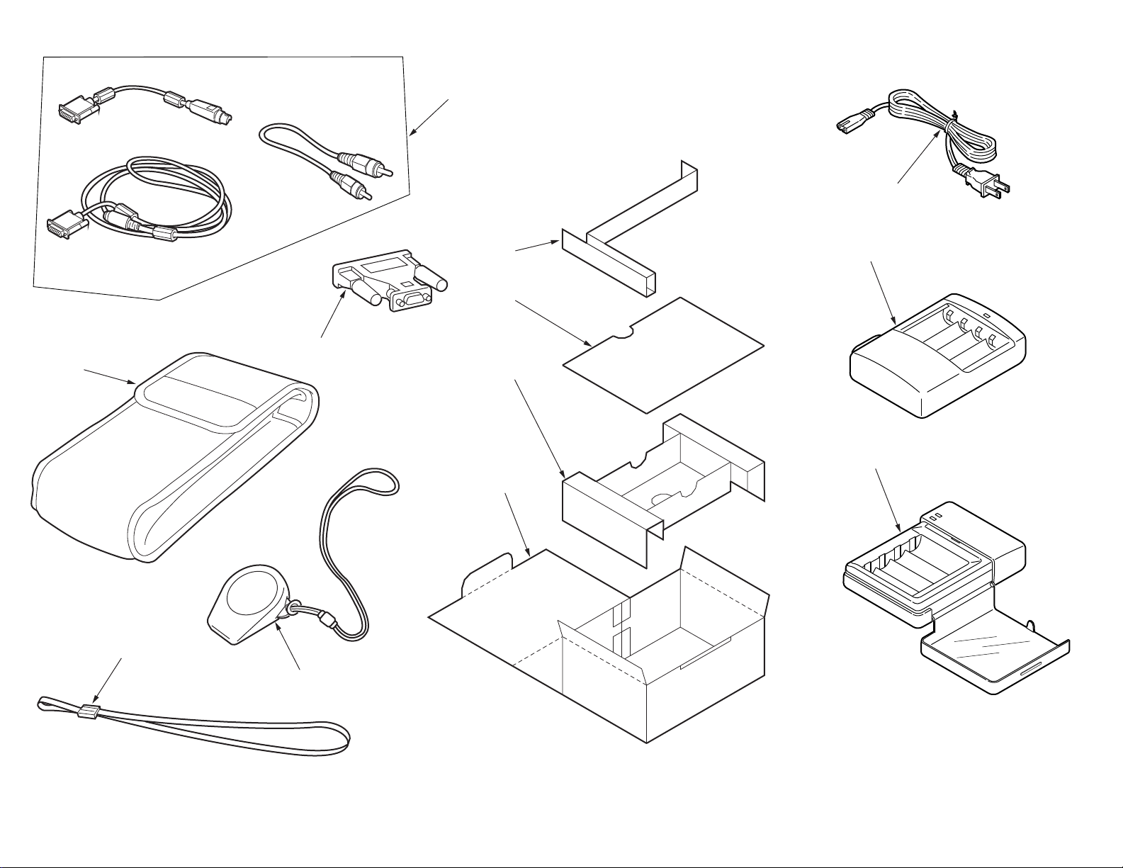
400
406
( FOR 200V )
405
( EXCPT EAI )
402
EPSON
202
for japan only.
04
03
02
01
404
( FOR 200V )
403
( FOR 100V )
EPSON
EPSON
401
PACKING MATERIALS FOR CP-700Z/PHOTO PC 750Z
 Loading...