

Page 1
6(59,&(0$18$/
&RORU6WLOO'LJLWDO&DPHUD
EPSON
PhotoPC 700
EPSON PhotoPC700
®
4009250
Page 2

NOTICE
All rights reserved. No part of this manual may be reproduced, stored in a retrieval system, or
transmitted in any form or by any means, electronic, mechanical, photocopying, recording, or
otherwise, without the prior written permission of SEIKO EPSON CORPORATION.
The contents of this manual are subject to change without notice.
All effort have been made to ensure the accuracy of the contents of this manual. However,
should any errors be detected, SEIKO EPSON would greatly appreciate being informed of
them.
The above not withstanding SEIKO EPSON CORPORATION can assume no responsibility for
any errors in this manual or the consequences thereof.
EPSON is a registered trademark of SEIKO EPSON CORPORATION.
General Notice: Other product names used herein are for identification purpose only and may
be trademarks or registered trademarks of their respective owners. EPSON
disclaims any and all rights in those marks.
Copyright © 1996 SEIKO EPSON CORPORATION. Printed in Japan.
Page 3

PRECAUTIONS
Precautionary notations throughout the text are categorized relative to 1)Personal injury and 2)
damage to equipment.
DANGER
WARNING
The precautionary measures itemized below should always be observed when performing
repair/maintenance procedures.
Signals a precaution which, if ignored, could result in serious or fatal personal
injury. Great caution should be exercised in performing procedures preceded by
DANGER Headings.
Signals a precaution which, if ignored, could result in damage to equipment.
DANGER
1. ALWAYS DISCO NNECT T HE PRODUCT FROM THE POWER SOURCE AND PERIPHERAL
DEVICES PERFORMING ANY MAINTENANCE OR REPAIR PROCEDURES.
2. NOWORK SHOULD BE PERFORMED ON THE UNIT BY PERSONS UNFAMILIER WITH
BASIC SAFETY MEASURES AS DICTATED FOR ALL ELECTRONICS TECHNICIANS IN
THEIR LINE OF WORK.
3. WHEN PERFORMING TESTING AS DICTATED WITHIN THIS MANUAL, DO NOT
CONNECT THE UNIT TO A POWER SOURCE UNTIL INSTRUCTED TO DO SO. WHEN
THE POWER SUPPLY CABLE MUST BE CONNECTED, USE EXTREME CAUTION IN
WORKING ON POWER SUPPLY AND OTHER ELECTRONIC COMPONENTS.
WARNING
1. REPAIRS ON EPSON PRODUCT SHOULD BE PERFORMED ONLY BY AN EPSON
CERTIFIED REPAIR TECHNICIAN.
2. MAKE CERTAIN THAT THE SOURCE VOLTAGES IS THE SAME AS THE RATED
VOLTAGE, LIST ED ON THE SERIAL NUMBER/RAT ING PLATE. IF T HE EPSON PRODUCT
HAS A PRIMARY AC RATING DIFFERENT FROM AVAILABLE PO W ER SOURCE, DO NOT
CONNECT IT TO THE POWER SOURCE.
3. ALWAYS VERIFY THAT T HE EPSON PRODUCT HAS BEEN DISCONNECT ED FROM THE
POWER SOURCE BEFORE REMOVING OR REPLACING PRINTED CIRCUIT BOARDS
AND/OR INDIVIDUAL CHIPS.
4. IN ORDER TO PROTECT SENSITIVE MICROPROCESSORS AND CIRCUITRY, USE
STATIC DISCHARGE EQUIPMENT, SUCH AS ANTI-STATIC WRIST STRAPS, WHEN
ACCESSING INTERNAL COMPONENTS.
5. REPLACE MALFUNCTIONING COMPONENTS ONLY WITH THOSE COMPONENTS BY
THE MANUFACTURE; INTRODUCTION OF SECOND-SOURCE ICs OR OTHER
NONAPPROVED COMPONENTS MAY DAMAGE THE PRODUCT AND VOID ANY
APPLICABLE EPSON WARRANTY.
Page 4

PREFACE
This manual describes basic functions, theory of electrical and mechanical operations,
maintenance and repair procedures of PhotoPC700. The instructions and procedures included
herein are intended for the experienced repair t echnicians, and attention should be given to the
precautions on the preceding page. The chapters are organized as follows:
CHAPTER 1. PRODUCT DESCRIPTIONS
Provides a general overview and specifications of the product.
CHAPTER 2. OPERATING PRINCIPLES
Describes the theory of electrical and mechanical operations of the product.
CHAPTER 3. TROUBLESHOOTING
Provides the step-by-step procedures for troubleshooting.
CHAPTER 4. DISASSEMBLY AND ASSEMBLY
Describes the step-by-step procedures for disassembling and assembling the product.
CHAPTER 5. ADJUSTMENTS
Provides Epson-approved methods for adjustment.
CHAPTER 6. MAINTENANCE
Provides preventive maintenance procedures and the lists of Epson-approved lubricants and
adhesives
required for servicing the product.
APPENDIX
Provides the following additional information for reference:
• Connector pin assignments
• Electric circuit boards components layout
• Exploded diagram
• Electrical circuit boards schematics
Page 5

REVISION STATUS
Rev. Date Page(s) Contents
A 1998/05/12 All First release
Page 6

TABLE OF CONTENTS
PRODUCT DESCRIPTION
1.1 FEATURES ..........................................................................................1-1
1.2 PRODUCT SPECIFICATION................................................................1-2
1.2.1 Control Panel Specification......................................................................... 1-9
1.2.2 Specification of operation switches.........................................................1-13
1.2.3 LED Specification.......................................................................................1-14
1.2.4 Operation Specification.............................................................................1-14
1.2.4.1 Basic Setting..................................................................................... 1-14
OPERATING PRINCIPLES
2.1 OVERVIEW..........................................................................................2-1
TROUBLESHOOTING
3.1 OVERVIEW..........................................................................................3-1
DISASSEMBLY AND ASSEMBLY
4.1 OVERVIEW..........................................................................................4-1
4.1.1 Tools.............................................................................................................. 4-2
ADJUSTMENT
5.1 OVERVIEW..........................................................................................5-1
5.1.1 Preparation for Adjustment.........................................................................5-2
5.1.2 Initialization...................................................................................................5-3
5.1.3 Downloading Firmware................................................................................5-4
5.1.4 5100K AWB. AGC Adjustment..................................................................... 5-5
5.1.5 Flange-Back Adjustment .............................................................................5-7
5.1.6 Color Matrix Adjustment.............................................................................. 5-9
Page 7

MAINTENANCE
APPENDIX
7.1.1 Circuit Diagrams...........................................................................................7-1
7.1.2 Location Diagrams.......................................................................................7-2
Page 8

&+$37(5
PRODUCT DESCRIPTION
Page 9
PhotoPC 700
Chapter1 Product Description
1.1 FEATURES
PhotoPC700 is a compact and high performance digital camera equipped with total 1300K
pixels(available pixels 1200K) and built in Color LCD view monitor. Most of the parts are same as
those of PhotoPC600. Therefore, since this manual mentions only newly added parts and
functions and different points from PhotoPC600, refer to the Service Manual of PhotoPC600 for
other details.
High resolution color CCD applied
Optical size: 1/2.7 inch color area
Total Pixels: 1343(H) x972(V)
Available Pixels: 1290(H) x 966(V), 24 bit output
Unlike PhotoPC and PhotoPC500, since JPEG compression is performed on the circuit,
processing time after shooting is quite shortened.
Back-up function by capacitor for Date and Time setting is added.
In the PhotoPC600, the date and time setting is cleared when the battery energy runs out without
connecting AC adapter, since the back-up battery is not built in. However, in the PhotoPC700, the
setting data can be maintained more than 30 minutes since the capacitor with large capacity is
built on the SY1 board.
High serial interface is built in.
Data transmission speed is maximum 230Kbps. (However, serial communication speed at PC
side requires more than 19200bps)
White Balance: Auto white balance +Fixed white balance
Exposure Control: Program auto exposure + Manual adjustment
4MB Flash Memory Standard is built.(Compact flash memory cards are available)
Picture Size: 1280 x 960, 640 x 480, 1280 x 480(Panorama)
Viewfinder: Optical real image view finder
Shooting Mode: Digital two-times zoom, Panorama, Continuous shooting, Black and
White.
Direct print function: Direct printing is available just by connecting the camera and
printer(EPSON Stylus Photo, EPSON Stylus Photo700,
ESPSON Stylus Photo EX, EPSON Stylus Color 800, EPSON Stylus
Color600) and downloading exclusive utility to the camera without
using PC.
Following shows optional products for PhotoPC700.
Table 1-1. Options for PhotoPC700
Item Prescription Code
AC Adapter Universal B86703*
Compact Flash Card
Power Pack This pack includes the Ni-
MH battery charger and Ni-
MH rechargeable batteries.
PCMC2A Adapter B867041
Ni-MH batteries B81811*
4MB:B808311
15MB:B808301
B86703*
Note*)
Rev. A
The number represented by an asterisk varies, depending on the country.
1-1
Page 10
Chapter1 Product Description
2
1.2 PRODUCT SPECIFICATION
IMAGE DATA
CCD: ICX202AK(SONY)
Size: 1/27 inch color area
Total pixel: 1343(H) x 972(V) Approx. 1300K pixels
Available pixels: 1290(H) x 966(V) Approx. 1200K pixels
Image Quality: Super fine mode (4xVGA high quality image mode)
Fine mode (4xVGA high quality image mode)
Standard mode (VGA Standard quality mode)
OPTICAL
Focus: Auto focus
PhotoPC 700
CAUTION
When shooting the poor contrast or dark subject, there are some cases
that auto focus does not work well. Especially, the auto focus can not
operate normally for the subject that requires flash light. In this case,
focus the subject 1.5m forcibly and shoot it.
Shooting Range: Macro mode 0.1m - 0.5m
Normal mode 0.5m - infinity
Shutter: Mechanical shutter with electric iris control shutter
Auto flash/Forced flash: 1/30 - 1/500 sec.
Auto Off/: 1/4 - 1/5000 sec.
Sensitivity: Equivalent to ISO60(ISO110 at high sensitivity selected)
White Balance: Full Auto TTL(Color temperature 5100K at fixed mode)
Exposure Time: Program auto exposure
Manual exposure adjustment is available(±2)
Viewfinder: Optical real image view finder (View range80%)
Flash Range: 0.2m - 2.4m
CAUTION
Shooting within 0.2m at macro mode with flash light will be overexposure. Therefore, take enough light from outside when shooting.
Flash Mode: Auto
Flash Off
Forced Flash
LCD Shooting: Playback rate: 1/30 sec.
View range: more than 90%
Rev. A
1-
Page 11
Chapter1 Product Description
3
INTERNAL IMAGES
Internal Memory: 4MB(recording taken images, program area, focus value, white
balance adjustment value)
Expansion Memory: Compact flash memory cards are available (DOS format).
The number of Available images: See Table1-2 below.
Table 1-2. The number of Available Images only with internal memory
Mode Setting Display Available number of images
Standard
Fine
Super Fine
Fine Panorama
Super Fine Panorama
Zoom/Continuous
★
★★
★★★
★★
★★★
★
Average 45
Average 13
Average 6
More than 27
More than 13
More than 45
PhotoPC 700
CAUTION
Available number above is measured by EPSON.co., and the number
varies more or less depending on the subject.
If extension function such as direct printing is downloaded to the
camera body, the available number decreases according to that
program.
When the available number becomes 0, stand-by light(red) turns on
and becomes impossible to shoot. Although this is not malfunction,
some users misunderstand this phenomenon as malfunction.
The number of available images with various memories: See Table below.
Table 1-3. The Number of Available Images with Optional Memories
Setting Setting Display 4MB 10MB 15MB 20MB 24MB
Standard(640x480)
Fine (1280 x 960)
Super Fine
(1280x960)
CAUTION
Available number above is measured by EPSON.co, the number
★
★★
★★★
60 158 227 304 368
19 50 72 97 116
9 25 36 49 59
varies more or less depending on the subject. Also, the number in
the table above is just average number, therefore, actual number
does not reach to that average number in some cases, depending on
the result of JPEG compression.
If extension function such as direct printing is downloaded to the
camera body, the available number decreases according to that
program.
When the available number becomes 0, stand-by light(red) turns on
and becomes impossible to shoot. Although this is not malfunction,
some users misunderstand this phenomenon as malfunction.
Rev. A
1-
Page 12
Chapter1 Product Description
4
SHOOTING MODES
Normal Shooting: Color image(1280 x 960 super fine/1280x960 Fine/640x480
Standard)
Macro Mode: Shooting range: 0.1m - 0.5m
Continuous: 2 pictures per second
Up to 10 pictures available
Fixed VGA Class size(640 x 480 : Standard quality)
PhotoPC 700
CAUTION
Zoom: Digital two times zoom mode(only one mode) is available
Panorama: Panorama Size(1280x480: Super fine/Fine)
Monochrome mode: Monochrome(1280x960: Super fine/Fine)
White balance: Auto/Fix
Exposure adjustment: Auto/Manual(±2 levels)
Sensitivity: STD/High
Each setting mode range:See Table below.
Macro Off Off Off Off Off Off
Self timer Off Off Off Off Off Off
Panorama, Zoom Off Off Off Off On Off
Multi Frame Off Off On On On Off
White Balance Off Off On On On Off
Exposure
adjustment
available
High Sensitivity Off Off On On On Off
Note) “
Off” means the current setting will be invalid automatically, and “On” means that the
current setting is maintained.
When shooting at Continuous mode, flash is turned off forcibly.
Table 1-4. Valid range at various setting modes
Button
off
Off Off On On On Off
Main
power
operation
off
LCD Off Change
to
Playback
Auto-
Power
Off
Off due
to the
end of
battery
life
Rev. A
1-
Page 13
PhotoPC 700
5
Chapter1 Product Description
INDICATION/MONITOR
Monitor: 2 inch TFT color LCD
Clock: No back-up battery
Indications on the LCD monitor: The number of available image,
Exposure adjustment value is indicated by pressing Function
button.
Image quality setting mode: Condition of Continuous
mode/Fixed white balance is displayed.
Flash light mode
Macro mode
Self-timer mode
Indication of Memory card installed.
Battery low indication.
LED: Green: Ready
Orange: Half-shutter condition(focus lock operation)
Red light blinks: Processing(Performing JPEG compression)
Red light on: Memory is full, otherwise, camera is abnormal.
Built-in Clock: Date/Time setting data can be maintained by super capacitor.
(By the combination of capacitor and oscillator on the SY1
board, the setting data can be retained more than 30-minute.
However, 3 hours are required to charge the capacitor full)
Menu Setting/Other: Panorama, Zoom, Continuous, white balance setting,
Exposure setting, Date/Time setting, Alert beep setting,
LCD brightness setting, Energy-saving setting, image
Information display mode, Image play-back mode(normal or
multi), Magnification, Erase all photos, Copy photos, Get
Memory information, Format memory cards, Slide-show,
Extension function setting and Language setting.
DATA PROCESSING(COMPRESSION / DEFREEZING)
Data Processing: See Table below.
Table 1-5. Image Processing Time
Shooting Mode Display
Indication
Standard Mode
Fine Mode
Super Fine
CAUTION
The result above is based on using 4MB compact flash memory made
★
★★
★★★
Playback JPEG Compression
8 to 11 seconds Approx. 2 seconds
Approx. 6 seconds Approx.4 seconds
Approx.3 seconds Approx. 6 seconds
by San Disk and LCD On(View). Processing time varies depending on
each access time of Memory Card. Also, Processing time is influenced
by the file size of the taken image data.
after shooting
Rev. A
1-
Page 14
Chapter1 Product Description
6
SWITCHES
Shooting mode button: Quality setting
Image re-play mode: →: goes to next image.
←: goes to previous image.
→: Keep pressing: High speed scroll to next images, and
release the button to stop.
←: Keep pressing : High speed scroll to previous images, and
release the button to stop.
Function button: Exposure adjustment, support button to erase one image.
PhotoPC 700
CAUTION
During high speed scroll, images are indicated at low resolution.
When high speed scroll stops, standard resolution image is written
over the low resolution image.
PHYSICAL DIMENSION AND WEIGHT
Dimension: 142.5mm(W) x 69.8mm(H) x 48.8mm (D)
Weight: 280g(without batteries and band)
ELECTRICITY
DC input voltage(AC): Min.: DC 6.3V, Max.: DC 8V
OPERATION ENVIRONMENT (TBD)
Temperature: Operating 5 to 35 °C
Storage −20 to 60°C
Humidity: Operating 30 to 80%(without condensation)
Storage 10 to 80%
SAFTY STANDARD (TBD)
Temperature: VCCI Class B
EXPANSION CONNECTOR
Video signal output: NTSC
DC Input Terminal: 7V
Serial Terminal: RS-422/423
Transmission speed 19820 bps/38400 bps/ 57600/115200/
230400 bps.
Synchronous 900 K bps is possible for direct printing.
CAUTION
User’s PC requires serial port rate 19200 bps or higher for all EPSON
made digital cameras. If PC supports serial port rate Max. 9600 bps,
high speed serial I/F board must be installed.
Rev. A
1-
Page 15
7
BATTERY LIFE
Battery Life: Refer to Table1-6.
Table 1-6. Battery Life(Alkaline battery)
Camera Mode Alkaline Battery Life
VF mode shooting(LCD off) More than 800 pictures
View mode shooting(LCD on) Approximately, 80 minutes
Playback mode(LCD on re-play) Approximately, 90 minutes
AUTO-ENERGY SAVING FUNCTION
Auto shut-down: Refer to Table1-7.
Table 1-7. Auto Energy Saving
Camera Condition Timing of Shut down
Shooting(LCD off) No operation is done for 1 minute.
Shooting at LCD on
(View mode)
Playback mode Automatically power off after consecutive
PhotoPC 700
Chapter1 Product Description
• Save energy mode(SAVE):Power off right
after shooting.
• Save energy mode(NORM):Power off 30
sec. after shooting.
electric continuity for 5 minutes.
CAUTION
Auto energy saving mode is invalid when using AC adapter.
After auto energy saving is operated, the camera resumes continuity
by half-shutter operation(ordinary focus lock).
VIEW MODE MENU
Panorama/Zoom: Standard/Panorama/Zoom
Shooting setting: Continuous/White balance/Exposure/Sensitivity
Information Display: On/Off
PLAYBACK MENU
Setting: Clock setting(Year, Month, Date/Time)
Beep sound(On/Off)
Color brightness(7 levels)
Energy saving mode(SAVE/NORM)
Information Indication: On/Off(The number of available images, the number of taken
images, Shooting date and time)
Playback mode: Normal playback(single image)/Multi-photo playback(9 images)
Magnification: Two times magnification, scroll is available.
Other menu: Erasing images: Select Erase/All Erase
Lock: Select Lock/All Lock/ All Unlock
Memory information: The number of the pictures remaining, the
number of pictures you can take, Card
indication.
Copy: From camera to the card, From card to
camera.
Card format.
Rev. A
1-
Page 16

PhotoPC 700
8
Chapter1 Product Description
Slide Show: Auto playback, Pause is available.
Expansion Function: To install, use, and delete optional programs.
Language: English, Japanese, French, German, Italian, Portuguese or Spanish.
DIRECT PRINTING UTILITY
Function Overview: Image printing, Album printing, Index printing, Sicker printing, Date
printing, Auto-fine printing.
Support Printer: EPSON Stylus Photo, EPSON Stylus Photo700, EPSON Stylus
Color 800, EPSON Stylus Color 600 and EPSON Stylus Photo EX.
All models mentioned above fixed at 720 dpi.
Recommended Paper: A4(Photo Quality Glossy Film, Photo Quality Glossy Paper, Photo
Quality Ink Jet paper, Photo Quality Ink Jet Card), A6 Photo Quality
Paper.
Printing Function: Color Printing, Black and white printing, Sepia tone printing, Blue
tone printing.
Rev. A
1-
Page 17

PhotoPC 700
9
Chapter1 Product Description
1.2.1 Control Panel Specification
Refer to the Service Manual of PhotoPC600, since the specification and function of the control
panel is basically same as the ones of PhotoPC600. Following shows different indications or
meaning from PhotoPC600.
Table 1-8. Control LCD
Category Indication LCD light Explanation
View
Image quality
Monochrome
mode
Macro mode Indicates at the macro mode.
Timer Indicates during the self timer is on.
★
★★
★★★
★
★★
★★★
★★
B
W
★★★
B
W
★★
B
W
Standard(640x480)
Fine(1280 x960)
Super Fine(1280x960)
Blinks Standard(640x480)/Fixed white
balance
Blinks Fine(1280 x960) Fixed white balance
Blinks Super Fine(1280x960) Fixed white
balance
Fine(1280x960)/Monochrome
Super fine(1280x960)/Monochrome
Blinks
alternatively
Lights blinks alternatively at
continuous shooting.
Monochrome
Blinks when the self-timer is
operating.
Internal Memory The number of pictures that internal
memory can shoot.
Exposure adjustment values: (P2,
P1, 00, -1, -2) Current exposure
adjustment value is indicated by
pressing Function button at the
exposure adjustment available
mode.
Rev. A
1-
Page 18

0
Table 1-9. Control LCD(Cont.)
PhotoPC 700
Chapter1 Product Description
Category Indication Indication
Action
External Memory This brackets [ ] is indicated when
the external memory(compact flash
card) is installed.
The number indicates the number
of pictures in the external memory
(compact flash card).
Indicates current exposure
adjustment value(P2, P1, 00, -1, or
-2).
External memory error.
This error is indicated when
installing or removing the external
memory during image compression
processing or LCD On at power on.
This error may destroy memory or
image data.
Flash
AUTO
Auto flash mode(Same as
PhotoPC600)
Explanation
Forced flash mode (Same as
PhotoPC600)
Forced flash off mode(Same as
PhotoPC600)
Blinks Charging.
(Charging to the capacitor for
flash)
Battery life No indication Useable(Full energy)
Warning sign to indicate low
battery energy.
Blinks Indicates to change the batteries.
Rev. A
1-1
Page 19

Table 1-10. Shooting Mode
PhotoPC 700
Chapter1 Product Description
LCD Indication Resolution/
Mode
★★★
★★
★
★★★
B
W
★★
B
W
Table 1-11.Indication in shooting(LCD indication at View Mode)
LCD Indication Frame Color Mode Other LCD
1280x960
(Super fine)
1280x960
(Fine)
640x480
(standard)
1280x960(B/W)
(Super fine)
1280x960(B/W)
(Fine)
No indication Standard
Zoom Panorama Continuous
No support 1280x960 No support
No support 2380x960 No support
640x480 No support 640x480
(Blinks alternatively)
No support No support No support
No support No support No support
Green Macro
(Same as
PhotoPC600)
Indicates “MACRO”
for a few seconds.
shooting
★ ★
indication
Blue Monochrome(Same
Orange Digital two times
Black Belts at top and
bottom of the frame.
Red Continuous
as PhotoPC600)
Zoom(Same as
PhotoPC600)
Panorama (Same
as PhotoPC600)
shooting
(Same as
PhotoPC600)
Indicates
“MONOCHROME”
for a few seconds.
Indicates “ZOOM”
for a few sends.
Indicates
“PANORAMA”
for a few sends.
Indicates
“CAUTION” for a
few second.
Rev. A
1-11
Page 20

Chapter1 Product Description
2
Table 1-12. Indication in shooting(LCD indication at View Mode)(Cont.)
Mode LCD Indication Note
AF Lock
White Balance This is indicated at left top of LCD
“Ο” indication (Green)
This is indicated at right top of LCD
screen.
screen.
PhotoPC 700
Exposure Adjustment
[-2,-1,+1,+2]
Battery Energy This is indicated at the center of the
Setting image quality
à
B
W
Icon of exposure adjustment and value
are indicated at left top of the LCD
screen.
screen.
Image quality is indicated at left bottom
of the screen.
Shooting mode(Monochrome: This icon
is indicated next to image quality incon)
Shooting mode(Panorama:This icon is
indicated next to image quality icon)
Í
Shooting mode(Zoom:This icon is
indicated next to image quality icon)
CAUTION
Rev. A
Shooting mode(Continuous:This icon is
indicated next to image quality icon)
Available shooting number is indicated
at the center of screen bottom.
Â
Æ
Same LCD indications as they are shown in the table above are also
used at playback mode, except Macro mode.
The number of picture already taken.
(External memory card: This icon is
indicated at right bottom of the screen)
The number of picture already
taken.(Internal memory card: This icon
is indicated at right bottom of the
screen)
1-1
Page 21

PhotoPC 700
3
Chapter1 Product Description
1.2.2 Specification of operation switches
Figure below shows locations of operation switches and lists different points from PhotoPC600 in
the Table below.
A
B
C
D
K
Function
E
F
SELECT
Exposure
J
G
H
I
Table 1-13. Switch Function changed from PhotoPC600
No. VF mode View mode Playback mode During menu
display
K Not operate. Not operate. Not operate. Not operate.
K+H Exposure+1
Exposure +1 Not operate. Not operate.
(Note1)
K+I
Exposure−1
Exposure −1
Not operate. Not operate.
(Note2)
K+J Not operate. Erase images.
(Only while
Erase currently
indicated image.
Not operate.
processing image)
Note1):
It is necessary to set “MANUAL” in advance at the exposure adjustment
setting in the View mode menu for this exposure adjustment function.
Note2):
When K+J function(erase image) is performed at View mode, image can be erased
only when the image is processing right after shooting. If you miss this timing,
change the (LCD) monitor mode switch(“F” in the figure above) to Playback, then,
currently indicated image can be erased by pressing K+J switch again. Also, an
image(s) can be erased by the same procedure as PhotoPC600(selecting “Erase”
or “Erase Photo Menu” at playback mode).
Rev. A
1-1
Page 22

PhotoPC 700
4
Chapter1 Product Description
1.2.3 LED Specification
Refer to Service Manual of PhotoPC600 for the figure of indicator locations and operation
specification. Explanation of functions, which are already mounted at the PhotoPC600 are omitted
here.
1.2.4 Operation Specification
Each operation method for PhotoPC700 is explained below. However, since the same operations
or setting method as PhotoPC600 are omitted here, refer to Service Manual for PhotoPC600.
1.2.4.1 Basic Setting
SETTING THE DATE AND TIME
This setting request appears automatically from the LCD monitor when the camera is turned on for
the first time or the camera is left more than 30 minutes after removing batteries. Setting method
is same as the one of PhotoPC600.
CAUTION
PANORAMA SHOOTING(REFER TO TABLE BELOW)
Procedure Operation Switch Camera Mode Note
1 Set the LCD monitor mode switch
2 Press SELECT switch.
3 Everytime pressing SELCET
4 Press BACK switch at “Zoom”.
CONTINUOUS SHOOTING
Although the back-up battery is not mounted on the PhotoPC700,
instead, electrolytic capacitor can retain date and time setting
temporarily(up to 30 minutes). However, these data is erased 30
minutes after the battery energy runs out. When this happens, it is
necessary to set date and time again.
Table 1-14. Setting for Panorama Shooting
Panorama/Zoom mode
to “View”.
switch,
Standard→Panorama→Zoom.
Table 1-15. Setting for Continuous Shooting
Procedure Operation switch Camera Mode Note
1 Set the LCD monitor mode switch to
“View”.
2 Press SELECT switch.
3 Press navigation switches and select
continuous shooting.
4 Press SELECT switch. mode)
5 On/Off of Continuous shooting is
changed over by pressing SELECT
switch.
CAUTION
Rev. A
In case of continuous shooting, 2 pictures per second(up to 10
pictures) are available when pressing shutter button.
Panorama/Zoom mode
Conditions mode
(selecting continuos
1-1
Page 23

5
MACRO MODE
Operation method: Same as PhotoPC600
Shooting range: 10cm∼15cm
NORMAL PLAYBACK MODE
Table 1-16. Setting for Normal Playback Mode
PhotoPC 700
Chapter1 Product Description
Procedure
Order
1 Set LCD monitor mode switch to “Playback”. Playback mode
2
MULTI-PHOTO PLAYBACK MODE
Procedure
Order
1 Set LCD monitor mode switch to “Playback”. Playback mode
2 Press SELECT switch. Setting mode
3 Press navigation switches several times and
4 Everytime SELECT switch is pressed, it
5 Press “BACK” switch, selecting “Multi-photo”. Multi-photo playback
Navigation button(
previous image.
Navigation button(/) to go to the next
image.
Table 1-17. Setting for Multi-Photo Playback Mode
indicate “Playback mode” on the screen.
switches over Normal→Multi.
Operation switch Camera mode
Operation switch Camera mode
"/
) to go back to the
Note
(LCD monitor
menu)
Note
(LCD monitor menu)
Playback mode
mode.
MAGNIFICATION INDICATION
Table 1-18. Setting for Magnification Indication
Procedu
re order
1 Set LCD monitor mode SW to “Playback”. Normal playback
2 Indicate the image to enlarge by using
navigation switches. In case of multi-photo
playback, selected image is indicated with
white frame.
3 Press SELECT switch. Setting mode.
4 Select “Magnification display” by using
navigation switches.
5 Press SELECT switch. Magnification
6 Select the area you want to magnify by
navigation switches.
Currently selected area can be seen at left
top of the screen.
7 Press BACK switch to go back to Normal
Playback mode or Multi-photo playback.
Operation switch Camera mode Note
mode or
Multi-photo
playback
Magnification
mode.
mode.
Selection of
magnification part
mode.
Selection of
magnification part
mode.
Only central image
is magnified.
Rev. A
1-1
Page 24

6
ERASING IMAGES(RIGHT AFTER SHOOTING)
PhotoPC 700
Chapter1 Product Description
CAUTION
This method is valid only for a short time that the taken image is
compressed in the circuit, after the shutter-button is pressed. (Only
while the red LED located on the lens viewfinder blinks) If you miss this
timing and still want to erase the image, refer to Table 1-20.
Table 1-19.Erasing Images right after shooting
Procedure
order
1 Set the LCD monitor mode
2 Shoot by pressing the shutter
3 Press BACK switch, pressing
4 Erase only the selected image
CAUTION
Operation switch LCD monitor menu Note
SW to “View”.
button.
Function switch, while the still
image is displayed on the
LCD.
by pressing SELECT switch.
If you wish to erase a particular image or all images at once, perform
same procedure as that of PhotoPC600.
View mode
From focus lock to till
image.
Erase Photo(displayed
image)mode.
View mode. Press BACK switch to
Perform next
step(procedure 4) within
10 seconds, otherwise, it
escapes from Erase
photo mode.
cancel erasing photo.
Table 1-20.Operation to erase image(s)
Procedure
order
1 Set the LCD monitor mode
switch to “Playback”.
2 In the normal playback mode,
display the image you want to
erase by using navigation
switches. In the multi-photo
playback mode, select the
image with white frame by
navigation switches.
3 Press BACK switch, pressing
Function switch.
4 Erase the selected image by
pressing SELECT switch.
Operation switch LCD monitor menu Note
Playback mode
Normal playback
mode or
Multi-photo playback
Photo control (erase
photos)mode.
It goes back to
playback mode after
the image is erased.
Unlike the table above, it
does not escape from
the Erase Photo mode
even after 10 seconds.
Press BACK switch to
escape from the mode.
Rev. A
1-1
Page 25

7
WHITE BALANCE
PhotoPC 700
Chapter1 Product Description
Table 1-21. White Balance
Procedure
order
1 Set the LCD monitor mode SW to “View”. View mode.
2 Press SELECT switch. Panorama/Zoom mode.
3 Display “Conditions” mode by navigation
switches.
4 Press SELECT switch. Conditions mode.
5 Match the mark with an icon of white
balance by using navigation switches.
6 Everytime SELECT switch is pressed, it
changes over AUTO and FIX. Be sure
that FIX is selected.
7 Press BACK switch twice and go back to
View mode.
EXPOSURE ADJUSTMENT
Table 1-22. Setting for Exposure Adjustment
Procedure
order
1 Set the LCD monitor mode switch
to “View”.
2 Press SELECT switch. Panorama/Zoom
3 Display “Conditions” mode by
navigation switches.
4 Press SELECT switch.
5 Match the mark with an icon of
exposure adjustment by using
navigation switches.
6 Everytime SELECT switch is
pressed, it changes over AUTO
and MANUAL Make sure that
MANUAL is selected.
7 Press BACK switch twice and go
back to View mode.
8 Pressing Function button and
navigation switches, display the
value from −2 to +2 on the LCD
and control panel.
9 Select an appropriate exposure
adjustment value, checking the
subject condition on the LCD
screen.
10 Take a picture.
Operation Switch LCD monitor menu Note
Operation Switch LCD monitor menu Note
Conditions mode.
Conditions mode
(selecting white balance)
Conditions mode.
(white balance)
Shooting available at
View mode.
View mode.
mode.
Conditions mode.
Conditions mode.
(selecting exposure)
Conditions mode
(exposure)
Shooting available at
View mode.
Conditions mode
(Selecting exposure
adjustment value)
If the value is
00(center value), it is
displayed only on the
control panel and
does not display on
the LCD screen.
Rev. A
1-1
Page 26

8
HIGH SENSITIVITY SHOOTING
Table 1-23. Setting High Sensitivity shooting
PhotoPC 700
Chapter1 Product Description
Procedure
order
1 Set the LCD monitor mode switch
to “View”.
2 Press SELECT switch. Panorama/Zoom
3 Display “Conditions” mode by
navigation switches.
4 Press SELECT switch. Conditions mode
5 Match the mark with an icon of
sensitivity by using navigation
switch.
6 Everytime SELECT switch is
pressed, it changes over Standard
(STD) and High sensitivity. Make
sure that High sensitivity is
selected.
7 Press BACK switch twice and go
back to View mode.
Operation switch Camera mode Note
View mode
mode
Conditions mode
Conditions mode
(selecting Sensitivity)
Conditions mode
(Sensitivity)
Shooting available at
View mode.
Table 1-24. Setting for Energy Saving Mode
This setting is valid
even the image on
the LCD is turned off.
Procedure
order
1 Set the LCD monitor mode switch
to “Playback”.
2 Press SELECT switch. Settings mode
3 Press SELECT switch. Settings mode
4 Match the mark with an icon of
save power by using navigation
switch.
5 Everytime SELECT switch is
pressed, it changes over SAVE or
NORM. Select either one.
6 Press BACK switch twice and go
back to View mode.
Operation switch Camera mode Note
Playback mode
Settings mode
(selecting energy
saving)
Settings mode
(energy saving)
From function setting
mode to playback
mode.
Rev. A
1-1
Page 27

&+$37(5
OPERATING PRINCIPLES
Operating principles of PhotoPC700 is same as those of PhotoPC600. Therefore, refer to Chapter
2 on the Service Manual of PhotoPC600 for more details. Although there is no changes about
operating principles, since each board is used exclusively for PhotoPC700, be careful not to order
the parts of PhotoPC600.
Page 28

2.1 OVERVIEW
Here lists only changed or different parts from PhotoPC600.
Back-up system for date and time setting is applied.
It is possible to retain date and time setting data for 30 minutes (30 minute on the
specification, but actually approx. 60 minutes) by the super capacitor on the SY1 board.
Battery life is extended, since the channel of power controller(IC311) on the ST1 board is
divided fine according to each elements.
2 out of 4 flash memories on the CA2 board are completely determined as exclusive area
for up-loading data program.
Although AGC/CDS are controlled by independent ICs respectively on the CA1 board in
case of PhotoPC600, those ICs became one-chip in PhotoPC700.
PhotoPC700
Chapter2 Operating Principles
Rev. A
2-1
Page 29

&+$37(5
TROUBLESHOOTING
Since basic component and its functions are same as those of PhotoPC600, refer to Chapter3 on
the Service Manual of PhotoPC600. However, since the adjustment items for PhotoPC700 are
different from those of PhotoPC600, refer to Tabale3-1 and perform proper adjustments after
repairing or replacing parts or boards.
Page 30

PhotoPC700
Chapter3 Troubleshooting
3.1 OVERVIEW
Since board components and its functions are same as those of PhotoPC600, refer to Chapter3
on the Service Manual of PhotoPC600.
CAUTION
Adjustment items for PhotoPC700 are different from those of
PhotoPC600. Therefore, refer to the table below and perform proper
adjustments after changing or replacing parts.
In this product, there are 2 repair levels; first maintenance and
second maintenance. The service for second maintenance is allowed
to be done only by EPSON.Co. We do not guarantee the repair result
by the others. Refer to table below for distinction between first and
second maintenance.
Table 3-1. Criterion of First/Second Adjustment
No. Service Performed Required Adjustment Maintenance
1 Replacing CA1 board 1)Initialization
2)AWB AGC Adjustment
3)Color Matrix Adjustment
2 Replacing or re-assembling
Lens Unit, Optical filter, or
CCD.
3 Replacing CA2 board. 1)Initialization.
4 Replacing SY1 board. Not required. First maintenance.
5 Replacing ST1 board. Not required. First maintenance.
6 Replacing TB1 board. Not required. First maintenance.
1)Initialization.
2)AWB AGC Adjustment.
3)Flange-back Adjustment
4)Color Matrix Adjustment.
2)AWB AGC Adjustment.
3)Flange-back Adjustment
4)Color Matrix Adjustment
Second maintenance.
(Should be performed only
by EPSON.Co.)
Second maintenance.
(Should be performed only
by EPSON.Co.)
Second maintenance.
(Should be performed only
by EPSON.Co.)
(Repair is possible by
others)
(Repair is possible by
others)
(Repair is possible by
others)
Rev. A
3-1
Page 31

&+$37(5
DISASSEMBLY AND ASSEMBLY
Since the board component of PhotoPC700 is same as that of PhotoPC600, procedures for
disassembly and assembly are also same. However, since the soldering locations of lead wires
between boards are changed more or less, be sure to solder those wires correctly as they were
connected before.
Also, since adjustment items for PhotoPC700 are different from those of PhotoPC600, make sure
to perform corresponding adjustments by referring to Table4-1 and Chapter5. Only different
points, compared with PhotoPC600 are listed in this chapter.
Page 32

PhotoPC700
Chapter4 Disassembly and Assembly
4.1 OVERVIEW
Refer to Chater4 on the Service Manual of PhotoPC600 for disassembly and assembly.
CAUTION
In case of PhotoPC600, there are only 3 items as supply unit of electric
parts on the board; 1)2 fuses(F3102, F3103) on the ST1 board, 2)Flash
unit, 3)Main electrolytic condenser(C5412). Do not repair or replace
other electric parts except for these 3 items. Even if other electric parts
are replaced, the other adjustment procedures are not mentioned on the
Service Manual.
CAUTION
Adjustment items for PhotoPC700 are different from those of
PhotoPC600. Refer to the table below and check the required
adjustments for the repairs you are about to perform. Then, perform
necessary adjustments, referring to Chapter5 after the repair service
is done.
In this product, there are 2 repair levels; first maintenance and
second maintenance. The service for second maintenance is allowed
to be done only by EPSON.Co. We do not guarantee the repair result
by the others. Refer to table below for distinction between first and
second maintenance.
Table 4-1. Criterion of First/Second Adjustment
No. Service Performed Required Adjustment Maintenance
1 Replacing CA1 board 1)Initialization
2)AWB AGC Adjustment
3)Flange-back Adjustment
4)Color Matrix Adjustment
2 Replacing or re-assembling
Lens Unit, Optical filter, or
CCD.
3 Replacing CA2 board. 1)Initialization.
4 Replacing SY1 board. Not required. First maintenance.
5 Replacing ST1 board. Not required. First maintenance.
6 Replacing TB1 board. Not required. First maintenance.
1)Initialization.
2)AWB AGC Adjustment.
3)Flange-back Adjustment
4)Color Matrix Adjustment.
2)AWB AGC Adjustment.
3)Flange-back Adjustment
4)Color Matrix Adjustment
Second maintenance.
(Should be performed only
by EPSON.Co.)
Second maintenance.
(Should be performed only
by EPSON.Co.)
Second maintenance.
(Should be performed only
by EPSON.Co.)
(Repair service is possible
by others)
(Repair service is possible
by others)
(Repair service is possible
by others)
Rev. A
4-1
Page 33

PhotoPC700
2
Chapter4 Disassembly and Assembly
4.1.1 Tools
The table below shows the tools recommended for repair service of PhotoPC700.
Table 4-2. Recommended Tools
No. Name Purchasable Code
1 5100 Kelvin Color Viewer X 103058400
2 DscCal_12 Adjustment Program X Attached with this manual book
3 Simens star chart X Included in the end of this book.
4 Precision Driver (+) O --5 Soldering iron O B740200100
6 A pair of tweezers O B641000100
7 Oscilloscope O --8
9 Color adjustment chart X 104268100
Note)
Windows95 environment(require
19200bps or higher for serial)
O means commercially available and X means not.
O ---
Rev. A
4-
Page 34

ADJUSTMENT
&+$37(5
CAUTION
Adjustment items of PhotoPC700 are different from those of
PhotoPC600. Here explains adjustment procedures only for
PhotoPC700. So, do not refer to Chapter5 Adjustment on the
PhotoPC600’s Service Manual.
Page 35

PhotoPC700
Chapter5 Adjustment
5.1 OVERVIEW
Here explains various adjustment for PhotoPC700. Refer to table below and perform appropriate
adjustment, if corresponding parts are exchanged in Chapter4.
CAUTION
In this product, there are 2 repair levels; first maintenance and
second maintenance. The service for second maintenance is allowed
to be done only by EPSON.Co. We do not guarantee the repair result
by the others. Refer to table below for distinction between first and
second maintenance.
We do not guarantee the repaired quality, if any second maintenance
is done by non-EPSON. Co..
Refer to section 4.1.5 “Procedure for Assembly” in the Service
Manual of PhotoPC600 for assembling after adjustment is done.
Table 5-1. Criterion of First/2nd Maintenance
No. Service Performed Required Adjustment Maintenance
1 Replacing CA1 board 1)Initialization
2)AWB AGC Adjustment
3)Flange-back Adjustment
4)Color Matrix Adjustment
2 Replacing or re-assembling
Lens Unit, Optical filter, or
CCD.
3 Replacing CA2 board. 1)Initialization.
4 Replacing SY1 board. Not required. First maintenance.
5 Replacing ST1 board. Not required. First maintenance.
6 Replacing TB1 board. Not required. First maintenance.
1)Initialization.
2)AWB AGC Adjustment.
3)Flange-back Adjustment
4)Color Matrix Adjustment.
2)AWB AGC Adjustment.
3)Flange-back Adjustment
4)Color Matrix Adjustment
Second maintenance.
(Should be performed only
by EPSON.Co.)
Second maintenance.
(Should be performed only
by EPSON.Co.)
Second maintenance.
(Should be performed only
by EPSON.Co.)
(Repair service is possible
by non-EPSON. Co.)
(Repair service is possible
by non-EPSON. Co.)
(Repair service is possible
by non-EPSON. Co.)
Rev. A
5-1
Page 36

PhotoPC700
2
Chapter5 Adjustment
Following table lists necessary tools for adjustment.
Table 5-2.Tools for Adjustment
No. Name Purchasable Code
1 5100 Kelvin Color Viewer X 103058400
2 DscCal_12 Adjustment Program X Attached with this manual book.
3 Simens star chart X Included I the end of this book.
4 Precision Driver (+) O --5 Soldering iron O B740200100
6 A pair of tweezers O B641000100
7 Oscilloscope O --8 Windows95 environment(require
19200bps or higher for serial)
9 Color adjustment chart X 104268100
Note)
O means commercially available and X means not.
O ---
CAUTION
In case of PhotoPC600, there are only 3 items except for lens unit on
the CA1 board as supply unit of electric parts on the board; 1)2
fuses(F3102, F3103) on the ST1 board, 2)Flash unit, 3)Main electrolytic
condenser(C5412). Do not repair or replace other electric parts except
for these 3 items. Even if other electric parts are replaced, the other
adjustment procedure are not mentioned on the Service Manual.
5.1.1 Preparation for Adjustment
This section explains setting up of camera and PC before starting adjustment. Follow the
procedures below and complete the setting-up before starting actual adjustment.
SETTING-UP PC
1. Use PC with Windows95.(Refer to caution below for details)
CAUTION
PC/AT compatible with 486 or higher CPU.
3.5-inch high-density diskette drive.
Serial port with standard RS-232C interface.
PC with 8M or higher available memory.
Hard disk drive with at least 15MB available.
VGA or SVGA monitor with at least 256-color display.
2. Insert the calibration software diskette into your diskette drive.
3. By double-clicking on “Setup.EXE” in the disk, a directory c:\DscCal52\ is automatically made,
and program is installed and completed.
Rev. A
5-
Page 37

PhotoPC700
3
Chapter5 Adjustment
5.1.2 Initialization
Initialization of PhotoPC700 clears following values and area. This adjustment should be done to
increase credibility in order to input new adjustment values when replacing CA2, CA1 boards, or
removing or exchanging Lens Unit, CCD or Optical filter.
1)5100K AWB. AGC Adjustment Values
2)Flange back Adjustment Values
3)Color Adjustment values
4)Available area for storing image data
Therefore, it is necessary to input all adjustment values except 4) mentioned above after
initialization is done.
1. Perform 1 to 3 procedures in section 5.1.1, and execute the adjustment program.
2. Following screen should be indicated.
Button for Initialization
Figure 5-1.Button Location for Initialization
3. Press Initialize button.
4. Since the screen to confirm the selection appears, press Y(Yes).
5. Initialization starts. After approximately 14 seconds of communication, although the screen
shows “Complete”, communication between PC and camera still lasts another 5 seconds.
Therefore, do not pull out the communication cables and also do not turn off the camera and
adjustment program until the communication display(★moves during processing) on the LCD
screen completely stops.
CAUTION
In order to acknowledge that initialization is completely done, do not
follow the indication on the screen but check that communication
display on the LCD screen(★★ movement) of the camera completely
stops, then go to the next procedure. If other operation is done in the
middle of communication, various adjustment values will remain
defective and give bad influence on the camera function.
Rev. A
5-
Page 38
PhotoPC700
4
Chapter5 Adjustment
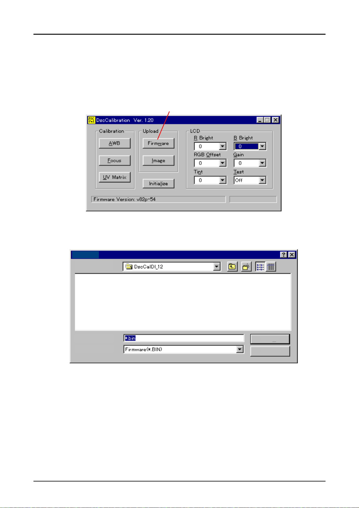
5.1.3 Downloading Firmware
Here explains downloading firmware. This section shows how to download bin file(∗.bin), which is
distributed from EPSON Co. according to the necessity, to the camera.
1. Perform 1 to 3 procedures in section 5.1.1, and execute the adjustment program.
2. Following screen is indicated.
Button for Downloading
Figure 5-2. Button Location for Downloading
3. Press Firmware button(for downloading).
4. Following screen appears.
Open
Look in:
§§§§§«ßæë
§§§§§«ßæë
File Name(N):
Files of Type(T):
Figure 5-3.Selecting Firmware File
Open
Cancel
5. Input directory on the hard disk or FD, which currently maintained Firmware is stored, into Drive
A, and select Firmware and press Open(O) button.
6. Since the screen to confirm the selection appears, press Y(Yes).
Rev. A
5-
Page 39

PhotoPC700
5
Chapter5 Adjustment
7. Downloading starts. After approximately 20 seconds of communication, although the screen
shows “Complete”, communication between PC and camera still lasts another 5 seconds.
Therefore, do not pull out the communication cables and also do not turn off the camera and
adjustment program until the communication display(★moves during processing) on the LCD
screen completely stops.
CAUTION
In order to acknowledge that initialization is completely done, do not
follow the indication on the screen but check that communication
display on the LCD screen(★★ movement) of the camera completely
stops, then go to the next procedure. If other operation is done in the
middle of communication, firmware is not written in the flash memory
completely, as a result, it won’t be able to recover again unless
exchanging CA2 board.
5.1.4 5100K AWB. AGC Adjustment
Here explains procedures how to input the values of auto white balance and auto gain controller.
This adjustment enables camera to automatically memorize color temperature, which is input
when the user emits light for flash. Since these adjustment values to input in this section are
stored with image data in the flash memory of the CA2 board, it is necessary to perform this
adjustment after performing initialization.
CAUTION
1. Turn on color viewer and leave it for 10 minutes until brightness settles. At this time, set the
volume of the color viewer to the maximum toward right direction.
2. Perform 1 to 3 procedures in section 5.1.1, and execute the adjustment program.
Perform section5.1.2 “Initialization” before performing this adjustment.
CAUTION
3. Following screen appears.
Locate the color viewer where there is as less fluorescent light or
light from widow as possible.
Use the color viewer 10 minutes after it is turned on, because
brightness is not stable right after the color viewer is turned on, and
correct values can not be input.
Button for AWB. AGC Adjustment
Figure 5-4. Button Location for AWB.AGC Adjustment
Rev. A
5-
Page 40

PhotoPC700
6
Chapter5 Adjustment
4. Locate the camera 18 cm away from the color viewer.
Note
)At this time, angle the camera lens to the color viewer surface correctly without capturing
the frame of color viewer or other objects
.
5. Press AWB button.
6. Since the screen to confirm the selection appears, press Y(Yes).
Note)
At this time, since the camera shoots 2 times, do not move your hand or camera until
adjustment values are indicated on the PC screen(about 10 seconds)
7. Following screen appears to indicate that adjustment is completed.(Numbers in the figure are
just examples)
Fixed value"128"
AWB Resu lts
1:
Rg=36 4
Gg=1 28
Bg=19 5
AGC= 15642880 20
2:
Rg=37 0
Gg=1 28
Bg=18 6
AveR g=367
AveGg =128
If either one of AGC
values indicates " 24 1",
AveB g=190
AGC= 15642880 20
it is error. If so, adjust
again.
Figure 5-5. Screen After AWB and AGC Adjustment
CAUTION
If AGC=241 is indicated, it is error. In this case, it is necessary to
perform adjustment again. If 241 is indicated again after the readjustment, it is necessary to replace CA1, CA2 boards, or CCD.
Values for Rg and Bg should be within from 200 to 400 respectively.
If their values are out of this range, same as above, it is necessary to
replace CA1, CA2 boards or CCD.
8. Press OK on the screen.
9. Adjustment result of AGC is changed from decimal number to hexadecimal number by using a
functional calculator.
In case of example in the figure above, 1 5 6 4 2 8 8 0 2 0(decimal number)
↓
5 D 3 D 2 4 1 4
10. The value which is changed to hexadecimal number becomes 4-byte(8 digits). From left, each
one byte(each 2 digits) is; AGC +2, AGC+1, AGC±0 and AGC−1. Therefore, in case of the
example in the figure above means;
AGC+2: 5D
AGC+1: 3D
AGC±0: 24
AGC−1: 14
Rev. A
5-
Page 41

PhotoPC700
7
Chapter5 Adjustment
11. Each hexadecimal number which is divided to one byte is again changed to decimal number
respectively. Example numbers will be;
AGC+2 (5D): 93
AGC+1 (3D): 61
AGC±0 (24): 36
AGC−1 (14): 20
12. Be sure that the value of AGC ±0 value is within 15 to 100. (36 in the example above)
The value of AGC = 15∼100
13. Input 4 numbers, which are changed to decimal number in procedure 11 above, into the
following 3 formulas, and be sure that each calculated value is within the following range.
Formula 1: (AGC+2) / (AGC+1)= Approximately 1.5(from the example above)
Formula 2: (AGC+1) / (AGC±0)= Approximately 1.7(from the example above)
Formula 3: (AGC±0) / (AGC−1)= 1.8(from the example above)
(AGC+2)/(AGC+1) = 1.1∼2.8
(AGC+1)/(AGC±0) = 1.1∼2.8
(AGC±0)/(AGC−1) = 1.1∼2.8
CAUTION
If each calculated value is not within the range above, adjust them
again. Also, if re-adjusted values are not within the rage again,
exchange CA1, CA2 boards or CCD.
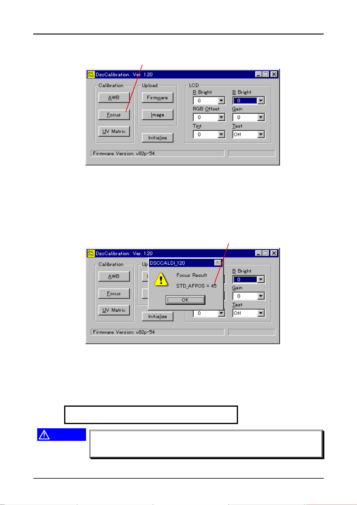
5.1.5 Flange-Back Adjustment
Here explains adjustment procedure to input a flange-back value. This adjustment adjusts focus to
the subject (Siemens star chart), which is located a certain distance away from the camera, and
stores that value as standard value. This adjustment should be done when replacing the lens unit,
CCD and CA2 board. Also, even when the lens unit, CCD or optical unit is disassembled and
assembled, this adjustment should be performed.
CAUTION
1. Perform 1 to 3 procedures in section 5.1.1, and execute the adjustment program.
Be sure to perform section 5.1.2 “Initialization” before starting this
adjustment. Also, make sure to perform section 5.1.4 “5100K AWB
Adjustment” after performing “Initialization”.
Rev. A
5-
Page 42
PhotoPC700
8
Chapter5 Adjustment
2. Following screen appears.
Button for Flange-back Adjustment
Figure 5-6. Button Location for Flange-Back Adjustment
3. Project a Siemens star chart, which is attached in the end of the manual book, at a distance of
69cm ± 3cm in front of the camera lens.
4. Press “Focus” button on the screen.
5. Since the screen to confirm the selection appears, press Y(Yes).
Be sure that adjustment
value is within 34 to 60.
Figure 5-7.Screen to confirm the Result After Adjustment
6. The camera shoots one time automatically and Flange-back adjustment value appears on the
screen.
7. Be sure that adjustment value appeared on the screen(45 in the example above) is within the
range 34 to 60.
Flange-back (Focus) adjustment value = 34∼60
CAUTION
If the value is not within the range above, adjust it again. Also, if readjusted value is not within the rage again, exchange CA1, CA2 boards
or CCD.
Rev. A
5-
Page 43

PhotoPC700
9
Chapter5 Adjustment
5.1.6 Color Matrix Adjustment
This adjustment is newly added adjustment to PhotoPC700. Performing this adjustment makes it
possible to realize more vivid color image.
CAUTION
1. Perform 1 to 3 procedures in section 5.1.1, and execute the adjustment program.
2. Following screen appears.
Be sure to perform section 5.1.2“Initialization” before starting this
adjustment.
Button for Color Matrix
Figure 5-8. Button Location for Color Matrix Adjustment
3. Turn on color viewer and leave it for 10 minutes until brightness settles. At this time, set the
volume of the color viewer to the maximum toward right direction.
4. Locate the Color adjustment chart in front of the color viewer. (Locate the Color adjustment
chart as if it covers the surface of the color viewer)
CAUTION
5. Locate the camera so that the distance between the camera lens and color viewer becomes
15cm.
Locate the color viewer where there is as less fluorescent light or
light from widow as possible.
Use the color viewer 10 minutes after it is turned on, because
brightness is not stable right after the color viewer is turned on, and
correct values can not be input.
Rev. A
5-
Page 44
PhotoPC700
0
Chapter5 Adjustment
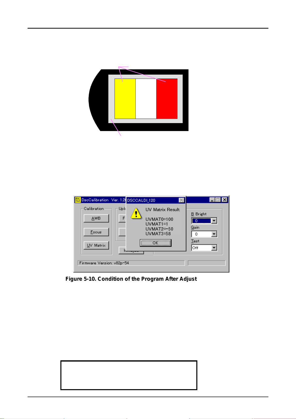
6. By selecting “Monitor” in the test buttons on the program, make sure that the camera lens is
capturing the color adjustment chart as it is shown below.
Be sure that 3 colors for color adjustment chart
appears on the screen correctly.
EPSON
Be sure that gray out-frame of
Figure 5-9. Camera Angle Before Adjustment
7. After checking the camera angle as it is shown above, turn Off “Monitor” setting on the
adjustment program so that the image is not received on the LCD.
8. Press UV Matrix button.
9. Since the screen to confirm the selection appears, press Y(Yes).
10. The camera automatically shoots, and adjustment values appears on the screen.
color adjustment chart appears.
ÒÓ ÊÞñïæõ Ïâðòéñ
ÒÓʾѺ®
ÒÓʾѮº®
ÒÓʾѯºª²
ÒÓʾѰº²µ
Figure 5-10. Condition of the Program After Adjustment is done
11. Check each adjustment value by following instructions. Each value range is listed below.
UVMAT0: Check if the value is within the range or not.
UVMAT1: If this adjustment value is below 128, check if that value is within the range
or not. If this adjustment value is more than 129, check if the value, which
this adjustment value minus 256 (this adj.value − 256), is within the range or
not.
UVMAT2: If this adjustment value is below 128, check if that value is within the range
or not. If this adjustment value is more than 129, check if the value which
this adjustment value minus 256 (this adj.value − 256), is within the range or
not.
UVMAT3: Check if the value is within the range or not.
UVMAT0 = 57 ∼ 157
UVMAT1 = −30 ∼ 30
UVMAT2 = −70 ∼ −19
UVMAT3 = 5 ∼ 105
Rev. A
5-1
Page 45

&+$37(5
MAINTENANCE
Maintenance for PhotoPC700 is same as that of PhotoPC600. Refer to Chapter6 in the Service
Manual of PhotoPC600.
Page 46

APPENDIX
&+$37(5
CAUTION
The connections among boards and function of connector pins of
PhotoPC700 are not different from those of PhotoPC600. Therefore,
refer to Chapter7 of the PhotoPC600 Service Manual. However, since
the circuit diagrams used for PhotoPC700 are only for PhotoPC700,
refer to the diagrams in this chapter.
Page 47

PhotoPC700
Chapter7 Appendix
7.1.1 Circuit Diagrams
Following pages show circuit diagrams mounted in the PhotoPC700; 1)SY1 board, 2)CA2 board,
3)CA1 board and 4)ST1 board.
Rev. A
7-1
Page 48

PhotoPC700
2
Chapter7 Appendix
7.1.2 Location Diagram
Following pages show the locations of electric parts mounted on the each board (CA2, CA1, SY1,
TB1 and ST1 boards).
Rev. A
7-
Page 49

2
100
29
100
25
100
100
11
17
16
12
13
14
100
101
1
101
100
101
9
18
101
8
22
21
102
10
20
4
3
5
6
7
102
100
102
19
24
102
23
100
Page 50

23
9
100
100
24
100
1
101
6
3
105
7
105
8
4
2
10
103
104
101
101
11
105
105
15
105
13
5
18
17
100
22
21
20
19
100
16
105
12
100
14
Page 51

04
200
150
151
203
03
02
01
PACKING MATERIALS FOR CP-600/PHOTO PC 700
 Loading...