

Page 1

SERVICE MANUAL
Color Still Digital Camera
EPSON PhotoPC600
®
4008224
Page 2

NOTICE
n All rights reserved. No part of this manual may be reproduced, stored in a retrieval system, or
transmitted in any form or by any means, electronic, mechanical, photocopying, recording, or
otherwise, without the prior written permission of SEIKO EPSON CORPORATION.
n The contents of this manual are subject to change without notice.
n All effort have been made to ensure the accuracy of the contents of this manual. However,
should any errors be detected, SEIKO EPSON would greatly appreciate being informed of
them.
n The above not withstanding SEIKO EPSON CORPORATION can assume no responsibility for
any errors in this manual or the consequences thereof.
EPSON is a registered trademark of SEIKO EPSON CORPORATION.
General Notice: Other product names used herein are for identification purpose only and may
be trademarks or registered trademarks of their respective owners. EPSON
disclaims any and all rights in those marks.
Copyright © 1996 SEIKO EPSON CORPORATION. Printed in Japan.
Page 3

PRECAUTIONS
Precautionary notations throughout the text are categorized relative to 1)Personal injury and 2)
damage to equipment.
DANGER
WARNING
The precautionary measures itemized below should always be observed when performing
repair/maintenance procedures.
Signals a precaution which, if ignored, could r esult in serious or fatal personal injury.
Great caution should be exercised in performing procedures preceded by DANGER
Headings.
Signals a precaution which, if ignored, could result in damage to equipment.
DANGER
1. ALWAYS DISCONNECT THE PRODUCT FROM THE POW ER SOURCE AND PERIPHERAL
DEVICES PERFORMING ANY MAINTENANCE OR REPAIR PROCEDURES.
2. NOWORK SHOULD BE PERFORMED ON THE UNIT BY PERSONS UNFAMILIER WITH
BASIC SAFETY MEASURES AS DICTATED FOR ALL ELECTRONICS TECHNICIANS IN
THEIR LINE OF WORK.
3. WHEN PERFORMING TESTING AS DICTATED WITHIN THIS MANUAL, DO NOT
CONNECT THE UNIT TO A POWER SOURCE UNTIL INSTRUCTED TO DO SO. WHEN
THE POWER SUPPLY CABLE MUST BE CONNECTED, USE EXTREME CAUTION IN
WORKING ON POWER SUPPLY AND OTHER ELECTRONIC COMPONENTS.
WARNING
1. REPAIRS ON EPSON PRODUCT SHOULD BE PERFORMED ONLY BY AN EPSON
CERTIFIED REPAIR TECHNICIAN.
2. MAKE CERTAIN THAT THE SOURCE VOLTAGES IS THE SAME AS THE RATED
VOLTAGE, LISTED ON T HE SERIAL NUMBER/RATING PLATE. I F THE EPSON PRODUCT
HAS A PRIMARY AC RATING DIFFERENT FROM AVAI LABLE POW ER SOURCE, DO NOT
CONNECT IT TO THE POWER SOURCE.
3. ALWAYS VERIFY THAT THE EPSON PRODUCT HAS BEEN DISCONNECTED FROM THE
POWER SOURCE BEFORE REMOVING OR REPLACING PRINTED CIRCUIT BOARDS
AND/OR INDIVIDUAL CHIPS.
4. IN ORDER TO PROTECT SENSITIVE MICROPROCESSORS AND CIRCUITRY, USE
STATIC DISCHARGE EQUIPMENT, SUCH AS ANTI-STATIC WRIST STRAPS, WHEN
ACCESSING INTERNAL COMPONENTS.
5. REPLACE MALFUNCTIONING COMPONENTS ONLY WITH THOSE COMPONENTS BY
THE MANUFACTURE; INTRODUCTION OF SECOND-SOURCE ICs OR OTHER
NONAPPROVED COMPONENTS MAY DAMAGE THE PRODUCT AND VOID ANY
APPLICABLE EPSON WARRANTY.
Page 4

PREFACE
This manual describes basic functions, theory of electrical and mechanical operations,
maintenance and repair procedures of PhotoPC600. The instructions and procedures included
herein are intended for the experienced repair t echnicians, and attention should be given to the
precautions on the preceding page. The chapters are organized as follows:
CHAPTER 1. PRODUCT DESCRIPTIONS
Provides a general overview and specifications of the product.
CHAPTER 2. OPERATING PRINCIPLES
Describes the theory of electrical and mechanical operations of the product.
CHAPTER 3. TROUBLESHOOTING
Provides the step-by-step procedures for troubleshooting.
CHAPTER 4. DISASSEMBLY AND ASSEMBLY
Describes the step-by-step procedures for disassembling and assembling the product.
CHAPTER 5. ADJUSTMENTS
Provides Epson-approved methods for adjustment.
CHAPTER 6. MAINTENANCE
Provides preventive maintenance procedures and the lists of Epson-approved lubricants and
adhesives required for servicing the product.
APPENDIX
Provides the following additional information for reference:
• Connector pin assignments
• Electric circuit boards components layout
• Exploded diagram
• Electrical circuit boards schematics
Page 5

REVISION STATUS
Rev. Date Page(s) Contents
A 1997/08/12 All First release
Page 6

TABLE OF CONTENTS
PRODUCT DESCRIPTION
1.1 FEATURES...........................................................................................1-1
1.2 SPECIFICATION .................................................................................. 1-2
1.2.1 Environmental Conditions........................................................................... 1-6
1.2.2 Electrical Specification ................................................................................ 1-6
1.2.3 EMI and Safety Standard.............................................................................. 1-6
1.2.4 Reliability....................................................................................................... 1-6
1.2.5 Operating Conditions................................................................................... 1-6
1.3 INTERFACE .........................................................................................1-7
1.3.1 Specification................................................................................................. 1-7
1.3.2 Control Panel (Display Panel)...................................................................... 1-8
1.4 CAMERA OPERATION........................................................................1-9
1.4.1 Control Buttons ............................................................................................ 1-9
1.4.2 LED Specification....................................................................................... 1-11
1.4.3 Operation Specification ............................................................................. 1-12
1.4.3.1 Basic Operation................................................................................. 1-12
1.4.3.2 Photo Format Setting........................................................................ 1-14
1.4.3.3 Macro Mode (Close Range Shooting)...............................................1-15
1.4.3.4 Basic LCD Settings........................................................................... 1-18
1.4.3.5 Setting the Playback Mode ............................................................... 1-21
1.4.3.6 Other Settings................................................................................... 1-22
OPERATING PRINCIPLES
2.1 OPERATING PRINCIPLES .................................................................. 2-1
2.1.1 Out line of Operating Principles.................................................................. 2-2
Page 7

TROUBLESHOOTING
3.1 OVERVIEW ..........................................................................................3-1
3.1.1 The camera has no power ........................................................................... 3-2
3.1.2 Red LED Light Blinking................................................................................ 3-3
3.1.3 Shutter does not work.................................................................................. 3-3
3.1.4 Image is taken out of cross mark in the viewfinder (Not using LCD
monitor).................................................................................................................. 3-3
3.1.5 Nothing appears on the Camera and Computer screens (All black)........ 3-4
3.1.6 Unable to transfer image data to PC........................................................... 3-4
3.1.7 No images on the LCD screen..................................................................... 3-5
3.1.8 Unable to use optional Compact Flash Card ............................................. 3-5
3.1.9 Picture is blurry or out of focus .................................................................. 3-5
DISASSEMBLY AND ASSEMBLY
4.1 OVERVIEW ..........................................................................................4-1
4.1.1 Precautions................................................................................................... 4-1
4.1.2 Tools.............................................................................................................. 4-2
4.1.3 Specification for Screws.............................................................................. 4-2
4.1.4 Procedure for Disassembly......................................................................... 4-3
4.1.4.1 Removing the Cabinet Parts............................................................... 4-4
4.1.4.2 Removing SY1 Board and ST1 Board ................................................ 4-5
4.1.4.3 Removing CA1 Board, CA2 Board, LCD and CCD............................. 4-6
4.1.5 Procedure for Assembly .............................................................................. 4-7
4.1.5.1 Installing the parts to the Front Cabinet.............................................. 4-8
4.1.5.2 Installing the parts to the Rear Cabinet............................................. 4-14
4.1.5.3 Connecting Holder Chassis and Lens Viewfinder............................. 4-18
4.1.5.4 Installing CCD and Lens Unit to the CA1 Board................................ 4-18
4.1.5.5 Connecting CA1 Board and CA2 Board............................................ 4-20
4.1.5.6 Connecting Holder Chassis and CA1 Board..................................... 4-26
4.1.5.7 Connecting LCD Monitor and LCD Holder........................................ 4-26
4.1.5.8 Connecting LCD Holder and CA2 Board........................................... 4-28
4.1.5.9 Connecting ST1 Board and CA2 Board............................................ 4-30
4.1.5.10 Connecting SY1 Board and CA2 Board.......................................... 4-34
4.1.5.11 Installing the Top Cover and Front Cabinet .................................... 4-38
4.1.5.12 Installing the Rear Cabinet and Battery Cover................................ 4-42
Page 8

ADJUSTMENT
5.1 ADJSUTMENT OVERVIEW ................................................................. 5-1
5.1.1 Preparation for Adjustment ......................................................................... 5-2
5.1.2 Initialization................................................................................................... 5-4
5.1.3 Downloading Firmware................................................................................ 5-6
5.1.4 5100K AWB Adjustment............................................................................... 5-7
5.1.5 Flange-Back Adjustment.............................................................................. 5-8
5.1.6 LCD H AFC Adjustment................................................................................ 5-9
5.1.7 LCD RGB Offset Adjustment ..................................................................... 5-11
5.1.8 LCD Gain Adjustment................................................................................. 5-12
5.1.9 LCD Blue Brightness Adjustment............................................................. 5-13
5.1.10 LCD Red Brightness Adjustment............................................................ 5-14
MAINTENANCE
6.1 PREVENTIVE MAINTENANCE............................................................ 6-1
6.1.1 Check Point................................................................................................... 6-1
APPENDIX
7.1 OVERVIEW ..........................................................................................7-1
7.1.1 Connection Between Boards....................................................................... 7-1
7.1.2 Connector Signals........................................................................................ 7-2
7.1.2.1 Major connector signals on the SY1 board ......................................... 7-2
7.1.2.2 Major connector signals on the ST1 board ......................................... 7-3
7.1.2.3 Major connector signals on the CA2 board......................................... 7-4
7.1.2.4 Major connector signals on the TB1 board ......................................... 7-4
7.1.3 Cable Connection Diagram.......................................................................... 7-5
Page 9

CHAPTER
PRODUCT DESCRIPTION
1
Page 10

PhotoPC600
Chapter 1 Product Description
1.1 FEATURES
PhotoPC 600 is high performance still digital camera equipped with 810K pixels and built in
Color LCD view monitor. Major features are following;
q High resolution color CCD applied
n Optical size: 1/3 inch format
n Total Pixels: 1016(H) x 774(V)
n Available Pixels: 962(H) x 774(V), 24 bit output
q Built in 2 inches color TFT LCD view monitor
q Built in High speed serial interface
Maximum data transfer speed is 115.2K bps, but PC requires serial port rate 19200 bps or
higher.
q Video output
n NTSC/PAL video output function
n Images can be displayed on the home TV by connecting the cable for the video to TV.
q Power supply
n 4 AA batteries(single-use alkaline, single-use lithium, rechargeable Ni-Cd, or rechargeable
Ni-MH)
*AA manganese can not be used.
n AC adapter available
q Automatic Focus: Automatic Exposure by CCD
q Internal memory: 4MB(for image and firmware and optional programs)
q External memory: Compact Flash memory available (4MB, 10MB, 15MB)
q Available photo modes
n Superfine mode (XGA)
n Fine mode (XGA)
n Standard mode (VGA)
q Direct print function
By using optional direct print adapter, direct printing from Stylus Photo is available.
Following shows optional products for PhotoPC600.
Table 1-1. Options for PhotoPC600
Item Name Code
Compact Flash Memory 4MB Compact Flash Card B808311
10MB Compact Flash Card ---
15MB Compact Flash Card B808301
AC Adapter 100-120 V/220-240 V B86703*
Stylus Photo Direct Print
Adapter
Communication kit Exclusive PhotoPC500 Software T.B.D
Exclusive Stylus Photo Software T.B.D
Note*)
Rev. A
The number represented by an asterisk varies, depending on the country.
1-1
Page 11

Chapter 1 Product Description
2
1.2 SPECIFICATION
IMAGE DATA
q CCD: ICX081AK (SONY)
q Size: 1/3 inch format, square pixel
q Total pixel: 1016(H) x 794(V) Approx.810K pixels
q Available pixels: 962(H) x 774(V) Approx.740K pixels
q Color: 16700K colors, 24 bits
q Resolution: Super fine mode (1024x768 pixels)
Fine mode (1024x768 pixels)
Monochrome super fine (1024x768 pixels)
Monochrome fine mode (1024x768 pixels)
Standard mode (640x480 pixels)
q Compression: JPEG
OPTICAL
PhotoPC600
q Lens: F2.8 (equivalent to 36mm lens on a 35mm camera)
q Aperture: F2.8, F5.6, F11 automatic change
q Focus: Auto Focus
q Range: 0.2m-0.5m (Macro mode)
0.5m-infinity (Normal mode)
q Shutter: Electronic shutter (1/8-1/500 sec.)
q Exposure: Equivalent to ISO100
q White Balance: Auto white balance (Rely on AWB adjustment circuit)
Full auto TTL
q Exposure Control: Program auto exposure by CCD detection
q Optical: Optical real image view finder, View range 80%,
Viewfinder Indication in the finder is marked by the cross mark
q Flash Range 0.2~2.4m(Flash control button; Auto®Forced flash On®Forced flash
Off)
Rev. A
1-
Page 12
Chapter 1 Product Description
3
INTERNAL IMAGES
q Internal compression: JPG format
q Internal Memory: 4MB
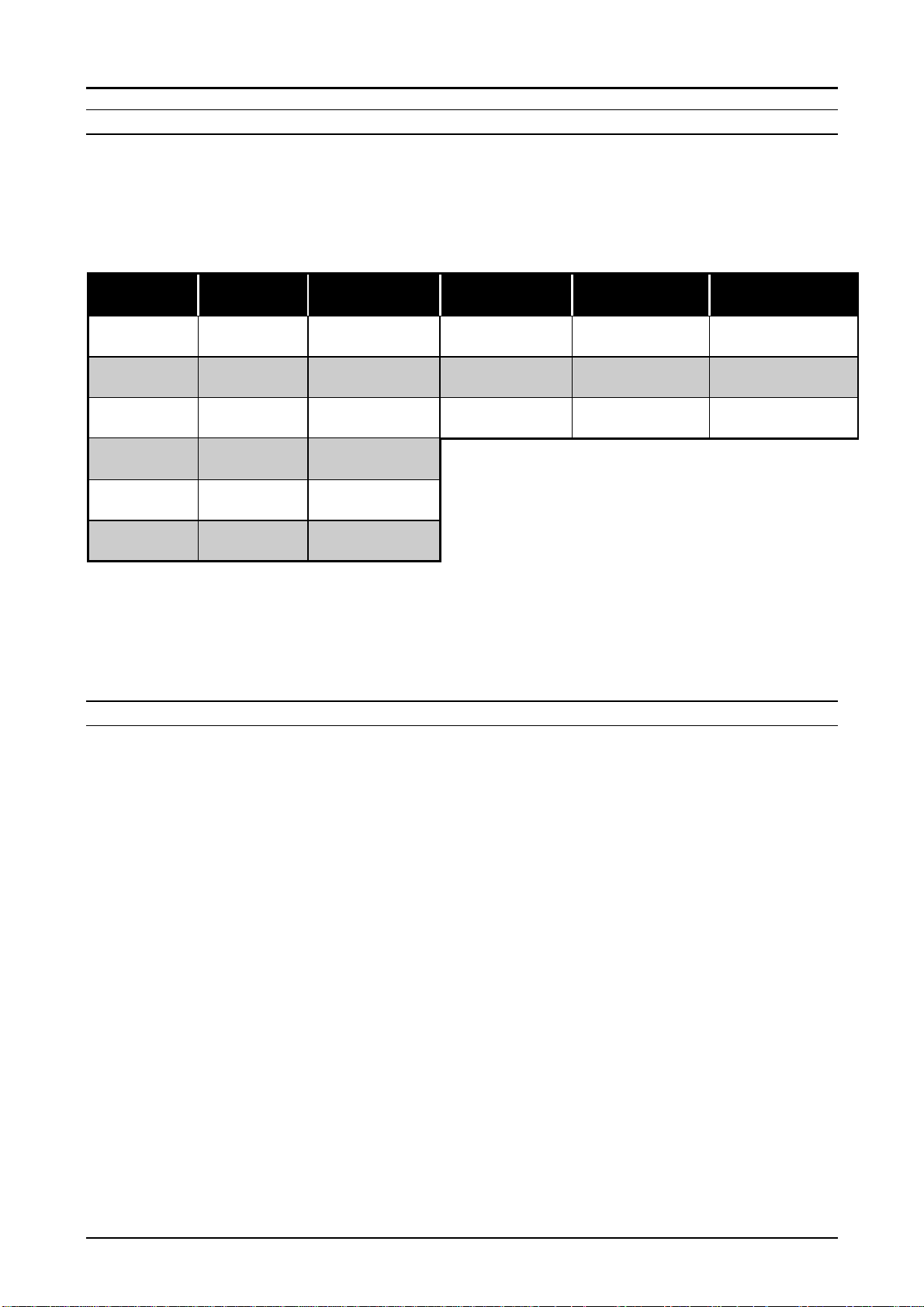
q Available number of images(photos) with memories.(See the Table below)
Table 1-2. Number of Available Images with Optional Memories
PhotoPC600
Mode Setting
Display
Super fine
Fine
Standard
Super fine
Panorama
Fine
Panorama
Zoom/Multiframe
Note1)
Note2)
SHOOTING MODES
In case the optional flash card is installed, internal memory(4MB) becomes invalid.
Therefore, the available number of images does not simply equal to the total number
of internal memory + compact flash memory. Using optional flash memory make it possible
to share the image data with PhotoPC500 or portable type of PC.
If the flash memory card is removed or installed while the camera is On, all the data will be
reset.
★★★
★★★
★★
★
★★
★
4M Internal
Memory
7 pictures
(Average:8)
16 pictures
(Average:18)
50 pictures
(Average:56)
14 pictures
(Average:16)
32 pictures
(Average:37)
50 pictures
(Average:56)
4M Compact
Flash Memory
Average 9 Average 25 Average 35
Average 21 Average 55 Average 79
Average 63 Average165 Average 238
10M Compact
Flash Memory
15M Compact
Flash Memory
q Normal shooting: Color image Super fine mode 1024x768 pixels
Fine mode 1024 x768 pixels
Standard mode 640x480 pixels
Note1)
q Self-timer mode: Picture will be taken 10 seconds by the clock counter.
q Macro mode range: 0.2m~0.5m
q Multi-frame mode: Continuous taking 9 images in a same picture at four intervals
Note2)
q Zoom mode: Digital step zoom (x1, x1.3, x1.6, x2.0, x2.5, x3.0)
Note3)
q Panorama mode: Panorama size image (1024x384)
Note4)
In the super fine and fine mode, quantity of information (File size) that image data
has varies even their resolution is the same.(Refer to the Table on the next page for
details.) Therefore, as a result, some differences are seen on the images even with the
same resolution.
(total time : 0.5, 1.0, 2.0, 3.0 seconds)
At the multi-frame mode, the shooting data is fixed at 640x480 pixels(VGA class).
At the zoom image mode, the shooting data is fixed at 640x480 pixels(VGA class).
Change the shooting size from 1024x768 to the rectangular
1024x384
In the panorama mode, since unused area appears on the top and bottom, the
available number of images increases.
Rev. A
1-
Page 13

PhotoPC600
4
Chapter 1 Product Description
q Monochrome mode: For taking black and white pictures (Monochrome fine and
Monochrome super fine)
Table 1-3. File Size and Resolution with Various Modes
Shooting Mode Resolution File Size
Super fine 1024x768 320KB
Fine 1024x768 160KB
Standard 640x480 60KB
Super fine (Panorama) 1024x384 160KB
Fine (Panorama) 1024x384 80KB
Zoom/Multi image 640x480 120KB
Super fine (Monochrome) 1024x768 160KB
Fine (Monochrome) 1024x768 80KB
INDICATOR/MONITOR
q LCD Monitor: 2 inches TFT color LCD
q Indications on the LCD monitor: 1)The number of pictures remaining
2)Image quality information
3)Flash mode
4)Macro mode
5)Self-timer mode
q Beep: On/Off
q Self-timer: Shooting in 10 seconds: blink slow(8 seconds) + blink
fast (last 2 seconds) = total 10 seconds
q Clock: No battery back up
Note)
Date and Time will be cleared when the batteries are removed from the camera.
(same as PhotoPC and PhotoPC500)
DATA PROCESSING
q Recording period: Standard mode About 11 sec.
Fine mode About 11 sec.
Super fine mode About 14~15 sec.
q Playback: Standard mode About 3 sec.
Fine mode About 6 sec.
Super fine mode About 8~11 sec.
Note)
SWITCHES
q Main power SW: Rotary switch with lens cover
q Monitor mode SW: 1)LCD view
q Control buttons: Macro mode (on/off)
q Select SW: Select, Back, Navigation buttons(4/5and
This processing time is only for internal memory. In case of using the optional flash
memory, these values varies, depending on the ability of access time by the memory.
2)Off
3)Image playback mode
Image quality (Standard/ Fine/Super fine)
Self-timer button(on/off)
Flash mode (on/off/Auto)
Shutter (half shutter: AF lock)
3/6buttons)
Rev. A
1-
Page 14
PhotoPC600
5
Chapter 1 Product Description
PHYSICAL DIMENSIONS AND WEIGHT
q Dimensions: 142.5mm(W) x 69.8mm(H) x 48.8mm(D)
q Weight: Under 250g (without batteries)
POWER SUPPLY
q Power supply: Require 4 batteries(single-use alkaline, single-use lithium,
rechargeable Ni-Cd, or rechargeable Ni-MH)
*AA manganese can not be used.
AC adapter available
CAUTION
Even AA size manganese batteries can be initially used, it is not
acknowledged as specification here since the battery life ends after
taking just a few images.
WARNING
Use only the AC adapter designed for PhotoPC600. Use of any other
adapter enables AC jack in the camera to operate abnormally and may
cause constant charging to the batteries.
EXPANSION CONNECTOR
q Video out: NTSC/PAL (NTSC model/PAL mode)
q DC input terminal: AC adapter(7V)
q Serial communication: Data input/output terminal (RS-422/423)
BATTERY LIFE
q Continuous shooting(without Flash operation): More than 400 pictures
q Shooting in View mode: Approximately 30 minutes
q Shooting in Playback mode: Approximately 90 minutes
Rev. A
1-
Page 15

Chapter 1 Product Description
6
1.2.1 Environmental Conditions
q Temperature: Operating 0 to 40 °C
Storage -20 to 60 °C
q Humidity: Operating 30 to 90% (no condensation)
Storage 10 to 90% (no condensation)
1.2.2 Electrical Specification
q Requirement of supply voltage for DC input (AC adapter)
Min. :DC 6.3 V
Max.:DC 8 V
q Absolute maximum supply voltage for DC input
Max. :DC 10 V
1.2.3 EMI and Safety Standard
PhotoPC600
q USA: FCC part15 subpart B class B
q Canada: CSA C108.8 class B
q Europe: EMC Directive 89/336/EEC EN55022 Class B
(CE-marking) EN61000-3-2
EN61000-3-3
EN50082-1
IEC801-2
IEC801-3
IEC801-4
Europe(NEMKO): EN55022(CISPR pub.22) class B
q Australia: AS/NZS 3548 class B
q Taiwan: EMI: CNS13438-C6357
1.2.4 Reliability
q FLASH memory life: 10K cycle write for FLASH memory
1.2.5 Operating Conditions
q Place: Ordinary home, office or outside
Rev. A
1-
Page 16

PhotoPC600
7
Chapter 1 Product Description
1.3 INTERFACE
PhotoPC600 can be connected to PC only by the serial interface (RS-232C compatible).
The minimum speed requirement of serial interface for PC is 19200 bps.
1.3.1 Specification
ASYNCHRONOUS
q Standard: RS-232C
q Communication Method: Asynchronous, 8bit, Non parity
q Communication speed: 19200, 38400, 57600,115200 bps
SYNCHRONOUS
q Standard: RS-422,423
q Communication Method: Synchronous, 8 bit, Non parity
q Communication speed: 230k bps - 900k bps
Rev. A
1-
Page 17
PhotoPC600
8
Chapter 1 Product Description
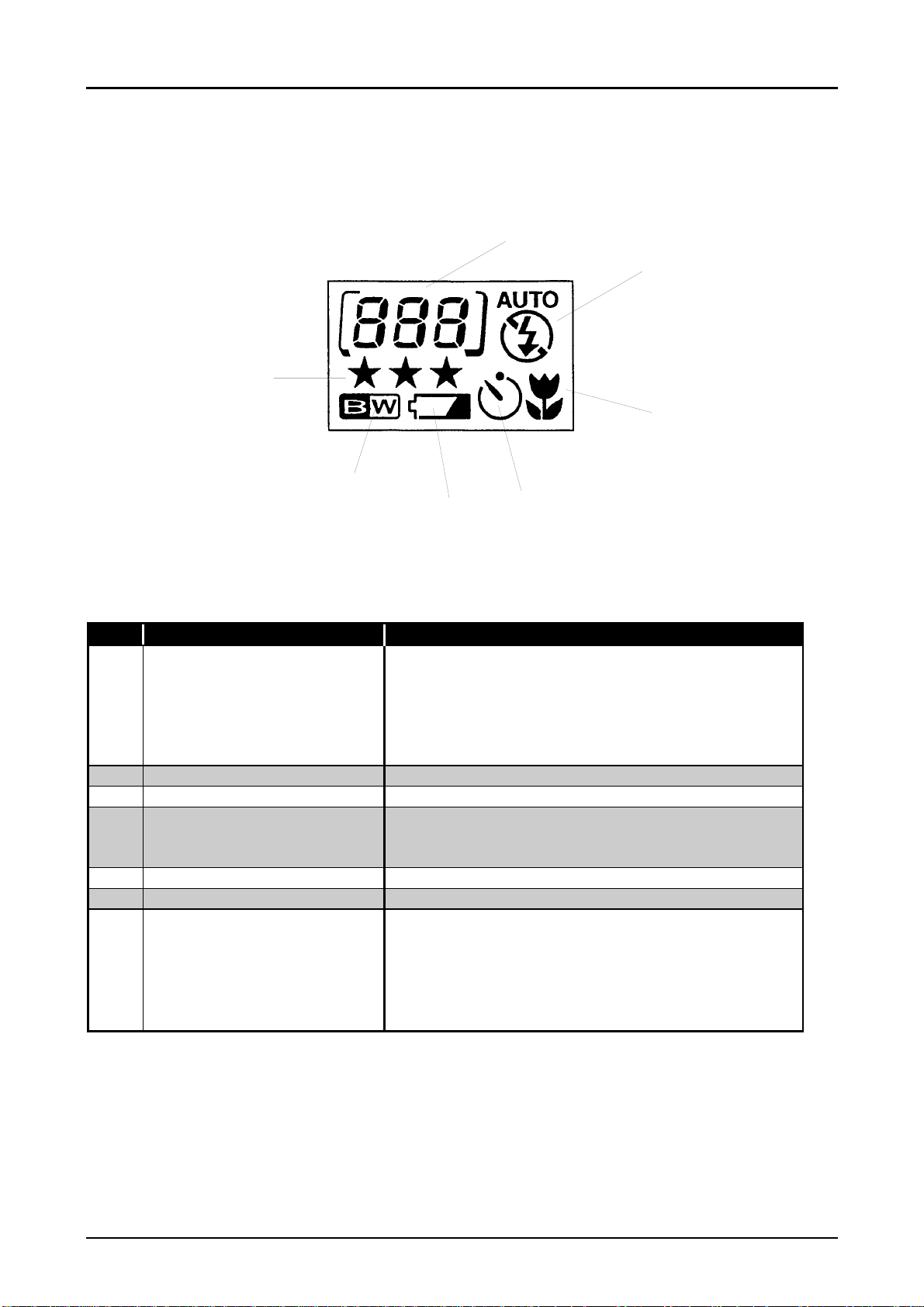
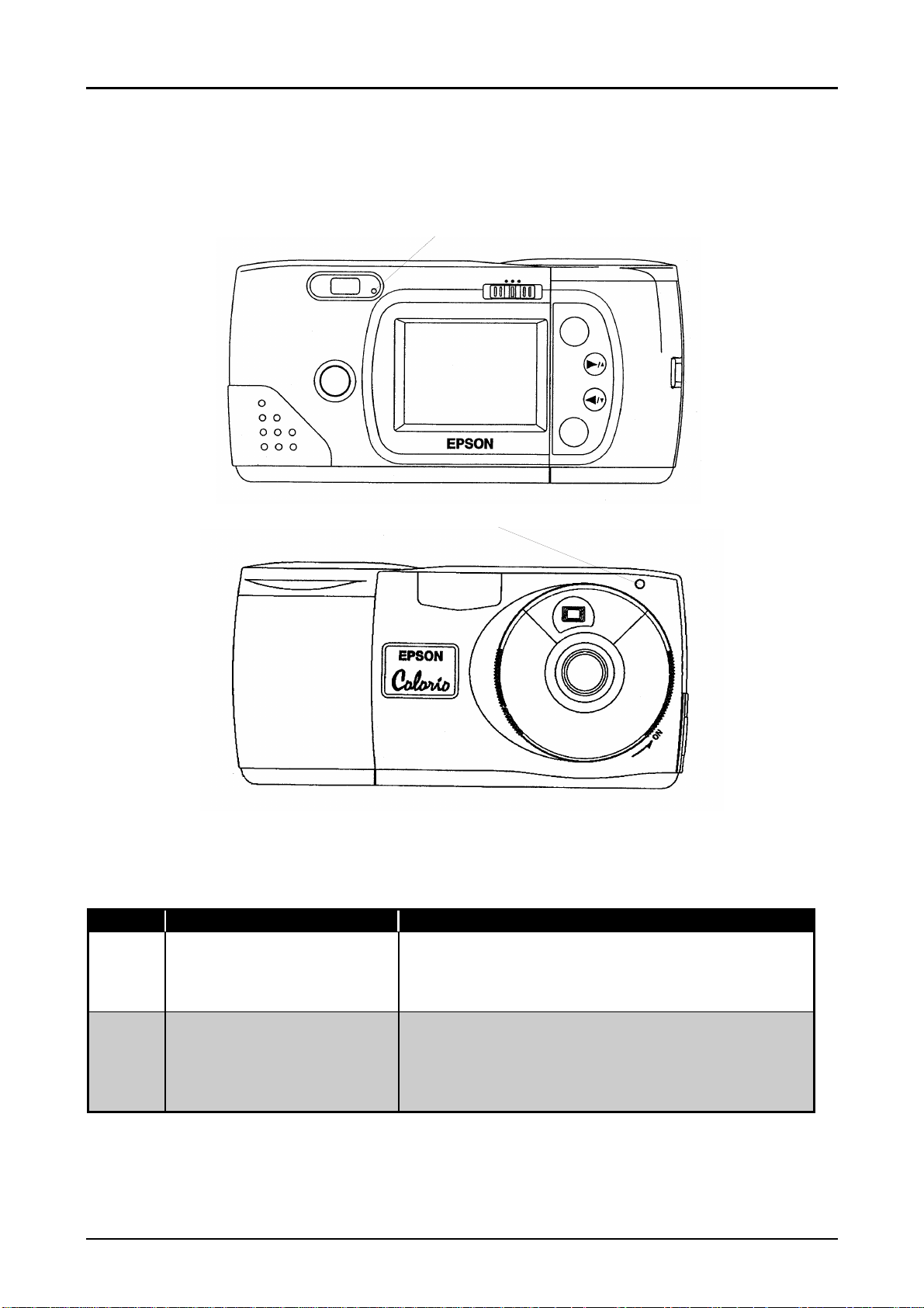
1.3.2 Control Panel (Display Panel)
The camera operation modes are displayed on the LCD. The following figure shows their
exteriors and 7 displays. Refer to the table below for the list of display meaning.
A
B
G
C
F
E
D
Figure 1-1. Display Panel
Table 1-4. Control Panel Indications
No. Display Meaning Additional Information
A The number of the
pictures remaining
B Flash mode 3 flash settings; Auto/Forced flash/Forced flash off
C Macro mode Indicates On/Off. (Range:0.2~0.5m)
D Self timer Shooting 10 seconds after pressing the shutter
E Battery life Indicate 3 battery conditions; Full/Half/End
F Monochrome mode Indicates On/Off
G Resolution (image quality) Indicates Standard/Fine/Super fine. However, the
Although the number of pictures you can take
increases or decreases depending on information
quantity (file size) that image data has, the minimum
number that you can take is guaranteed.
(The brackets
compact flash cards.)
button. (Timer light blinks 8 seconds slowly and 2
seconds fast.)
image quality for the following modes are
determined and Super fine resolution can not be
used.
·Zoom mode: Standard resolution(640x480)
·Multi-image mode: Standard resolution(640x480)
[ ]
appears when using an optional
Rev. A
1-
Page 18

9
1.4 CAMERA OPERATION
This section describes various buttons.
1.4.1 Control Buttons
DIGITAL AF CAMERA
1028x768 pixels
PhotoPC600
Chapter 1 Product Description
A
B
C
Figure 1-2. Control Buttons on the Top
Table 1-5. Button Functions on the Top
No. Button Name Function and Additional Information
A Shutter Shooting shutter (half shutter: AF lock)
B Image quality Pressing this button cycles the image quality
from one setting to another;
Standard/Fine/Super fine/Monochrome fine/
Monochrome super fine.
C Flash 3 modes; Auto/Forced flash/Forced flash off
D Self-timer Self timer On/Off
E Macro mode Macro mode On/Off
D
E
Rev. A
1-
Page 19
0
VIEW
OFF
PhotoPC600
Chapter 1 Product Description
F
G
PLAYBACK
K
Zoom.
Panorama
Multi.
SELECT
BACK
J
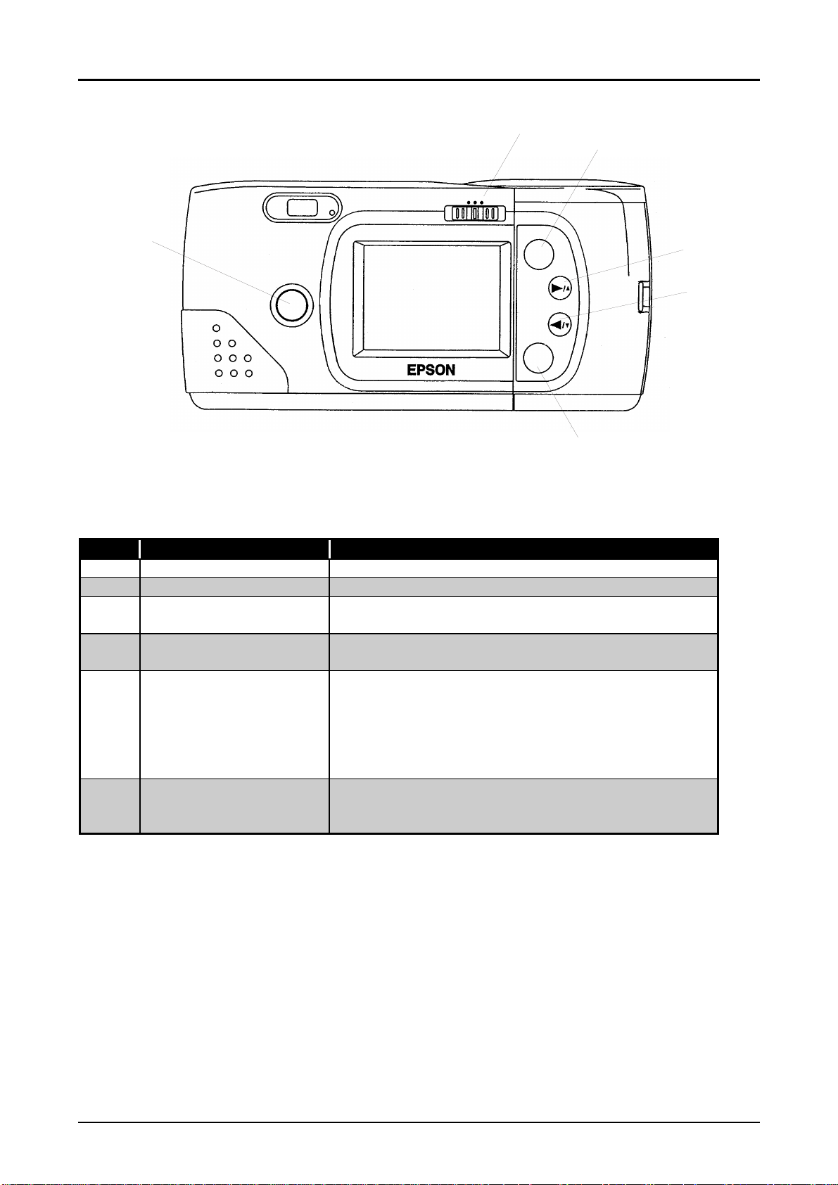
Figure 1-3. Buttons on the Back
Table 1-6. Button Functions on the Back
No. Button Name Function and Additional Information
F (LCD)Monitor mode SW 3LCD modes ; View/Off/Playback
G Select Select items during function settings
H Navigation button(1) Forward pictures or increase numbers during
the function settings.
I Navigation button(2) Backward pictures or decrease numbers
during the function settings.
J Back Back or exit from the present mode; Go back
to the image or screen before the function
setting, or go back to the previous number
during the date and time setting. Holding
down this button eventually leads to the
playback or view mode.
K Photo format button After entering to zoom mode by this button,
Panorama, Multi-frame can be set by the
navigation buttons.
H
I
Rev. A
1-1
Page 20
Chapter 1 Product Description
1.4.2 LED Specification
The following figure and table show the locations of the (LED) indicator lights and their
functions.
A
OFF
PLAYBACK
VIEW
PhotoPC600
Zoom.
Panorama
Multi.
SELECT
BACK
B
Figure 1-4. Locations of LED Lights
Table 1-7. LED Lights Indications
No. Name of light Function and Additional information
A Status Light During the image processing, red light
blinks. Green light is on when the camera is
ready for taking photo. Red light is on when the
shutter is half pushed.
B Timer Light After the self timer is set and the shutter
button is pressed, this light blinks slowly for
8 seconds and blinks fast for 2 seconds
(total 10 seconds) and then the picture is
taken.
Rev. A
1-11
Page 21
PhotoPC600
2
Chapter 1 Product Description
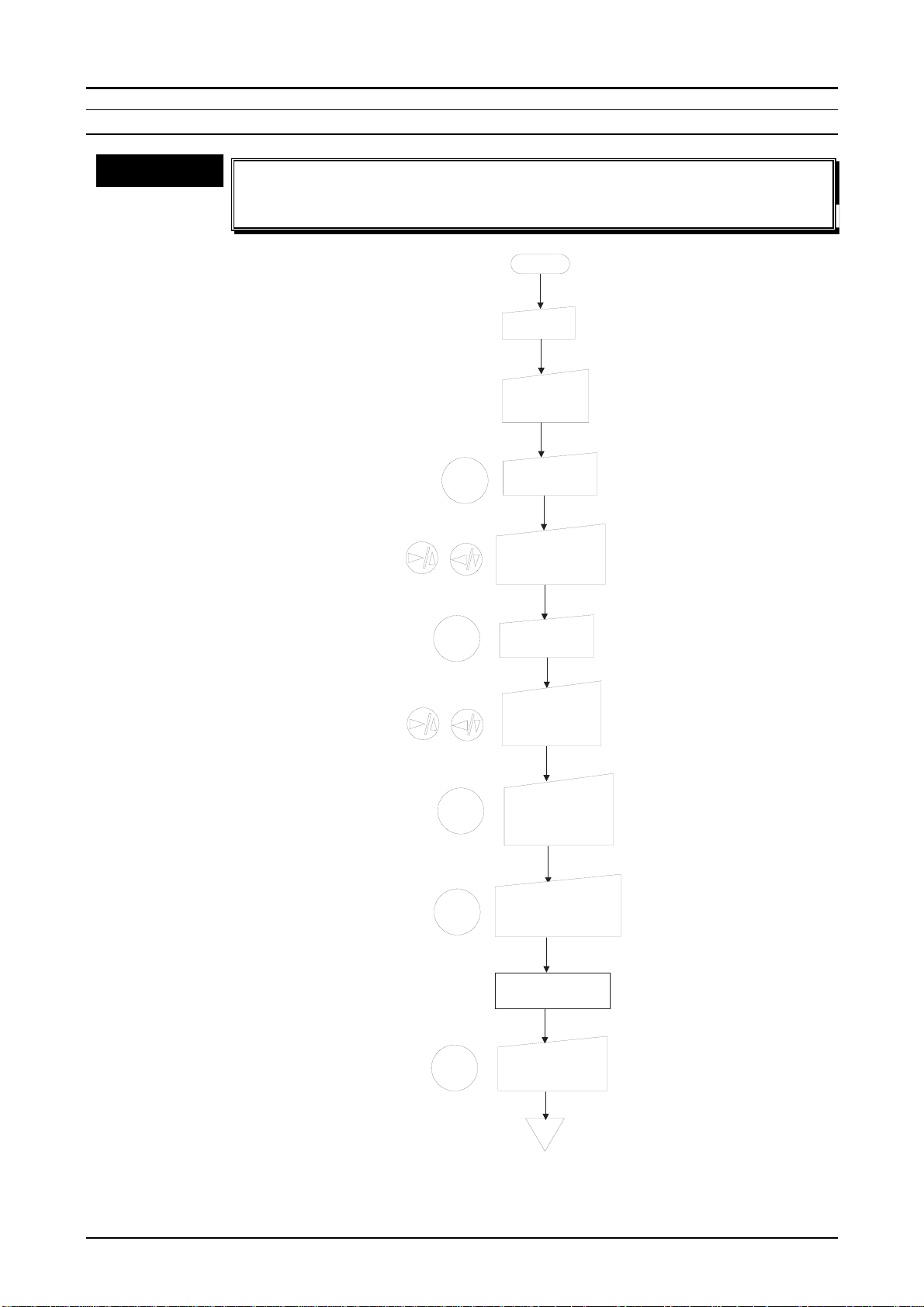
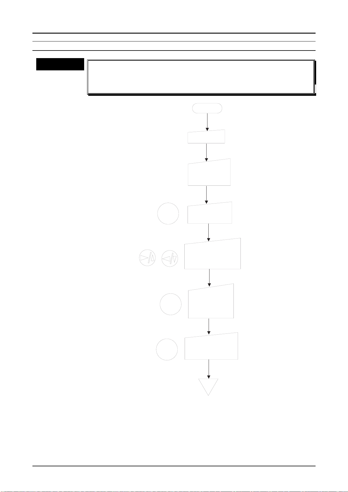
1.4.3 Operation Specification
Following flow charts show each operation methods.
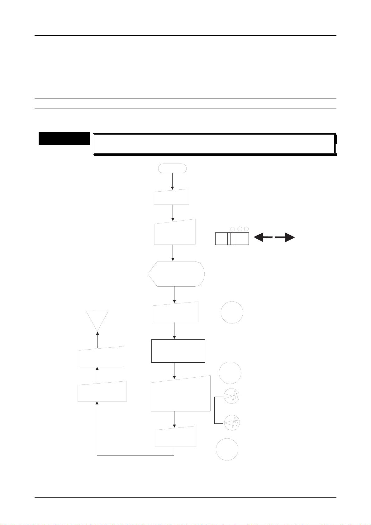
1.4.3.1 Basic Operation
SETTING THE DATE AND TIME(1)
The camera requests this setting automatically on the LCD monitor when the batteries are
installed for the first time or replaced.
CHECK POINT
üüüü
n
n
Since the PhotoPC 600 does not have back-up batteries, the date and
n n
time need to be set when the battery energy runs out.
START
Power O N
View O FF P layback
SELECT
END
Either V iew
m ode or
Playback O N .
Screen to reset
the date and tim e
appears.
Press the
SELECT button.
Screen for the
Trun off the
Power
T u rn o ff th e
M onitor m odeSW
selection for date
and tim e appears.
C onfirm by the
SE LEC T button and
change the num bers
by navigation buttons.
S e t to ta l
5 item s.
SELECT
BACK
G o to the next
item after
cinfirm ing
selection.
Increase or
decrease the
num ber.
Press this button
to g o b a c k to th e
previous item .
Figure 1-5. Setting the Date and Time (1)
Rev. A
1-1
Page 22
PhotoPC600
3
Chapter 1 Product Description
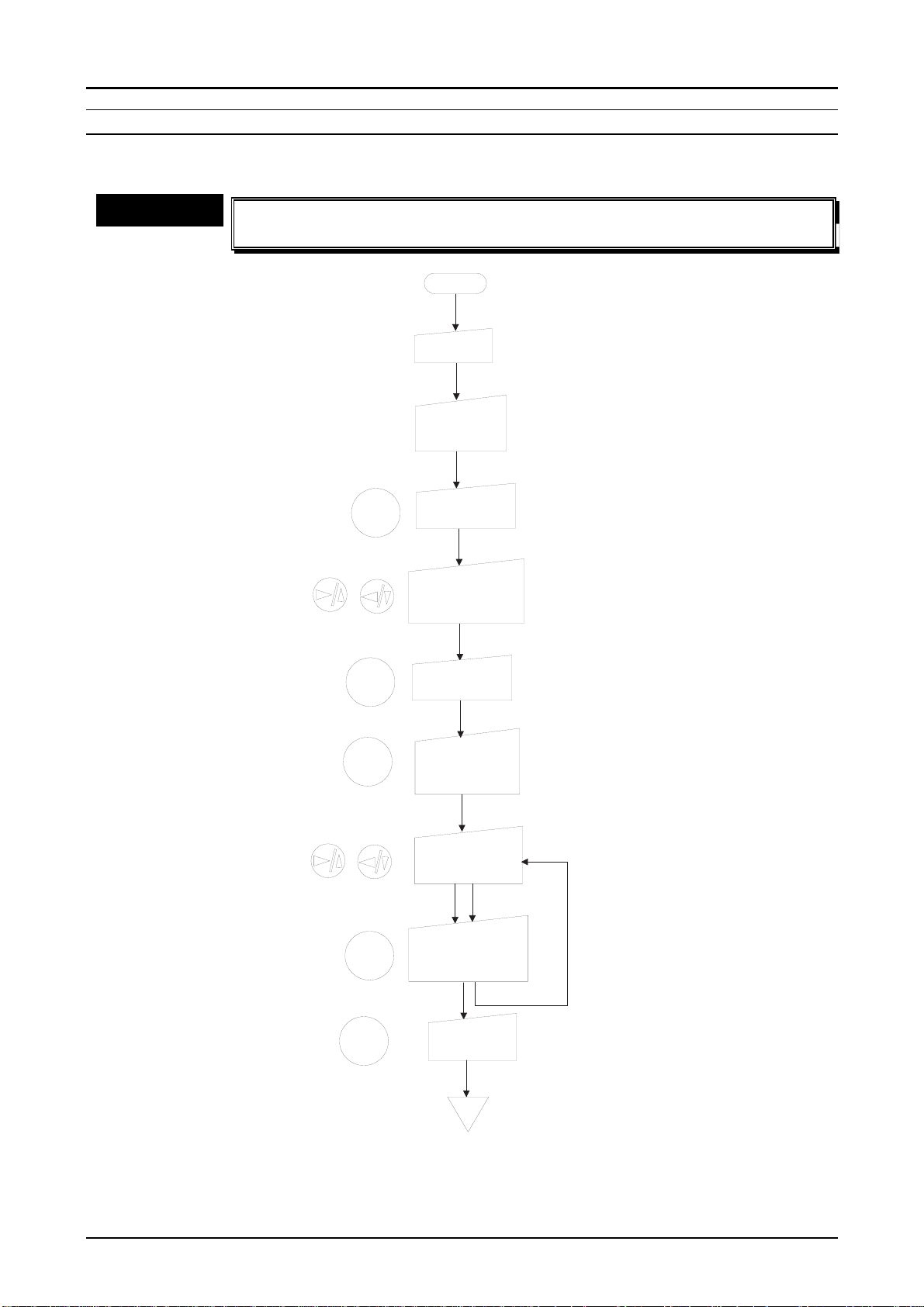
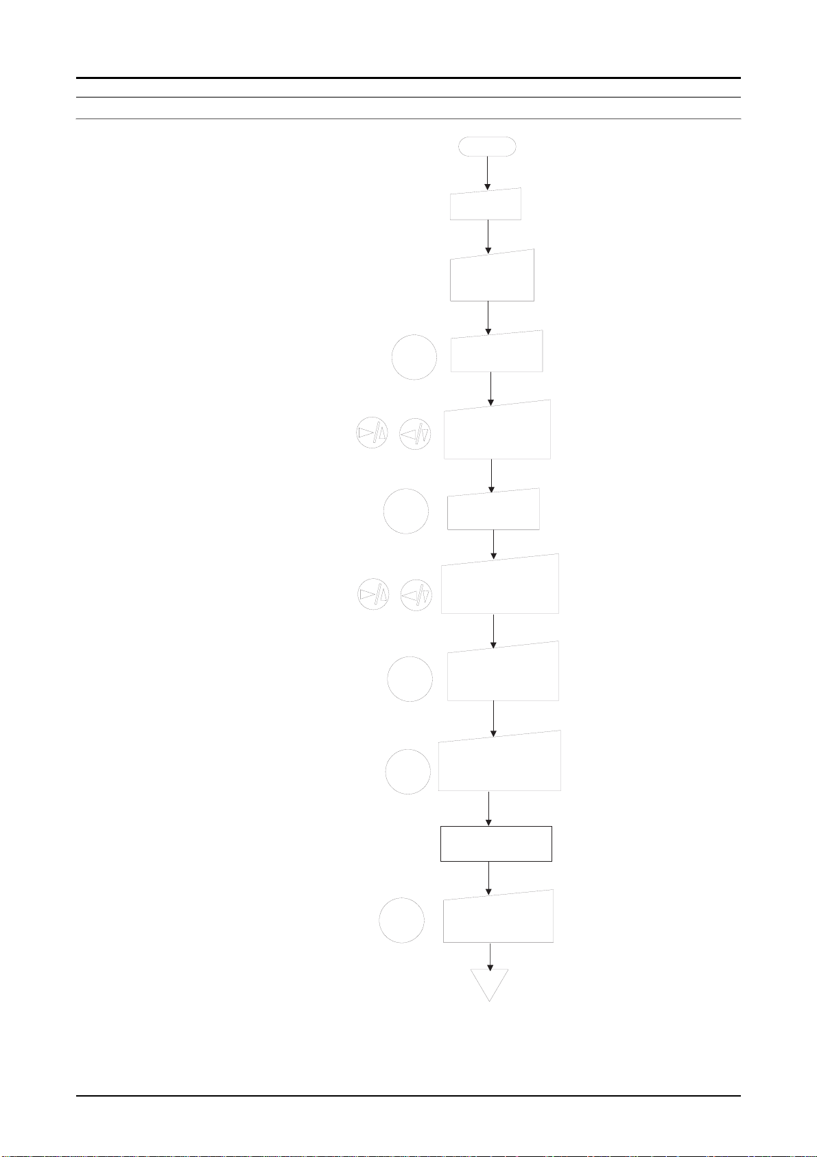
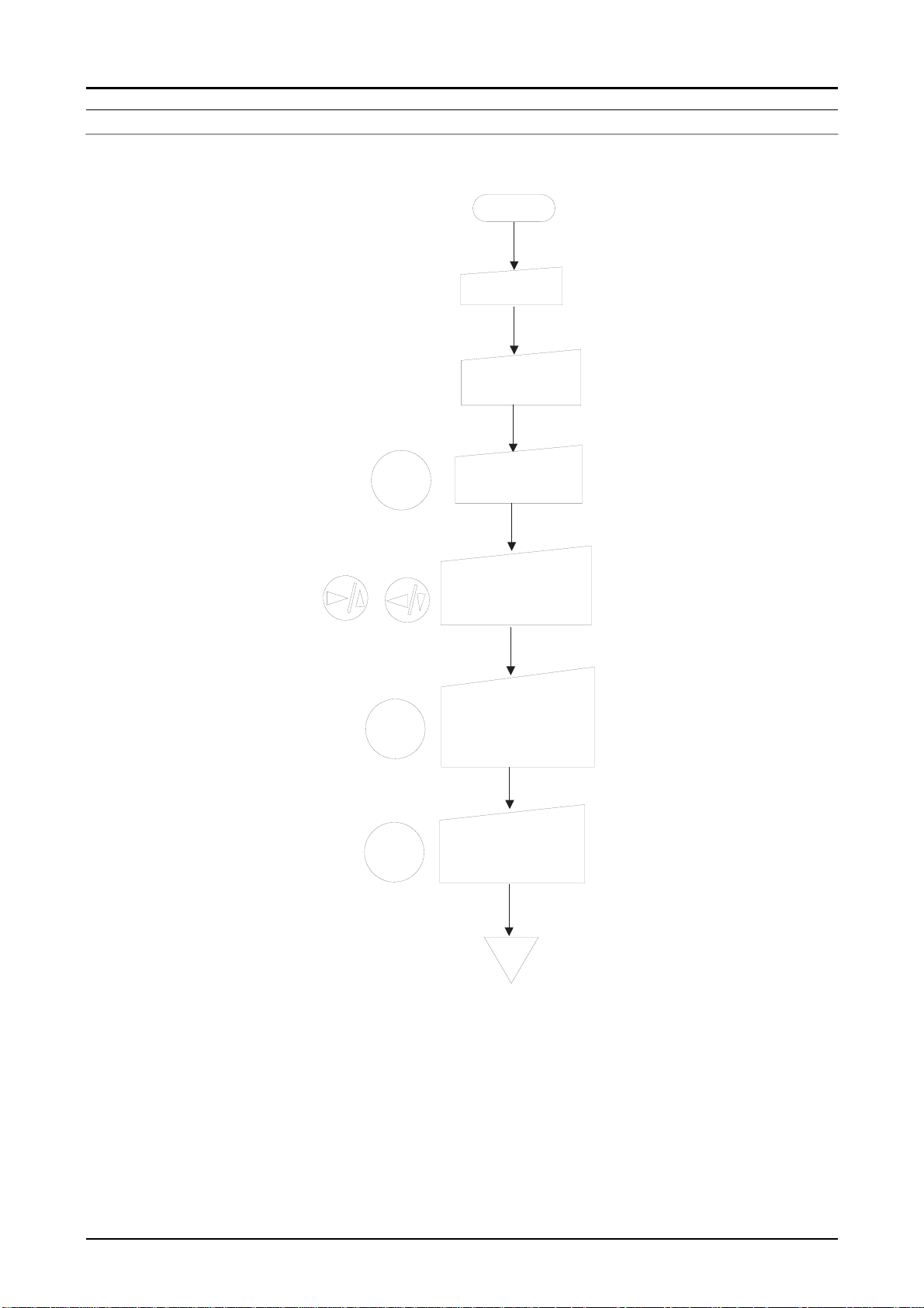
SETTING THE DATE AND TIME(2)
This setting is performed when you want to change the date or time even though they are
already set.
CHECK POINT
üüüü
n
n
Since the PhotoPC 600 does not have back-up batteries, the date and
n n
time need to be set when the battery energy runs out.
START
Power ON
Either View
mode or
Playback ON.
Press the
SELECT button.
Select "Settings"
menu by using
navigation buttons.
Press the
SELECT button.
At this time,
it enters the
clock setting
mode.
SELECT
SELECT
There is a red cursor
on the year.
At this time, the red
cursor moves to next
number.
Figure 1-6. Setting the Date and Time (2)
SELECT
SELECT
BACK
Press the
SELECT button
one more time.
Change the year
by the navigation
buttons.
Press SELECT
button after
changing numbers.
Press BACK
button twice.
END
Repeat this steps
for adjusting the rest
of month/date/hour/
minute.
Rev. A
1-1
Page 23
4
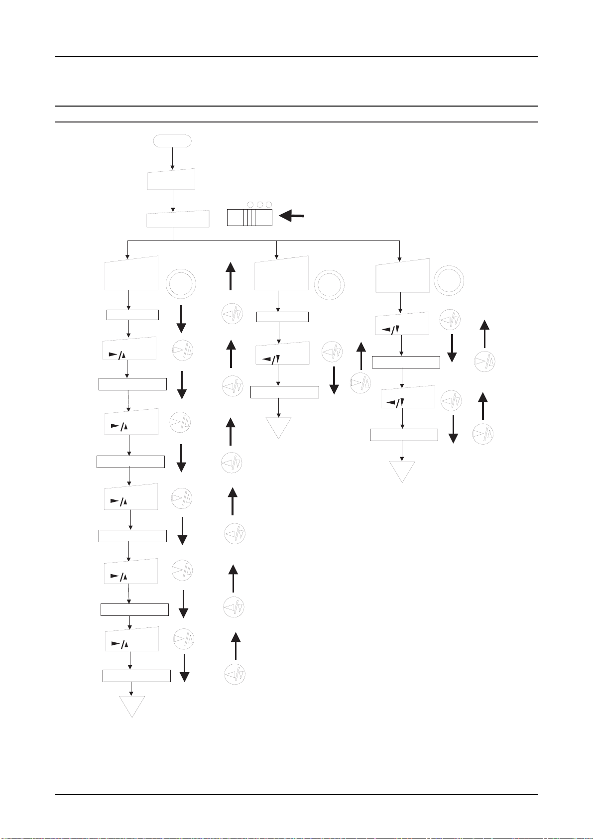
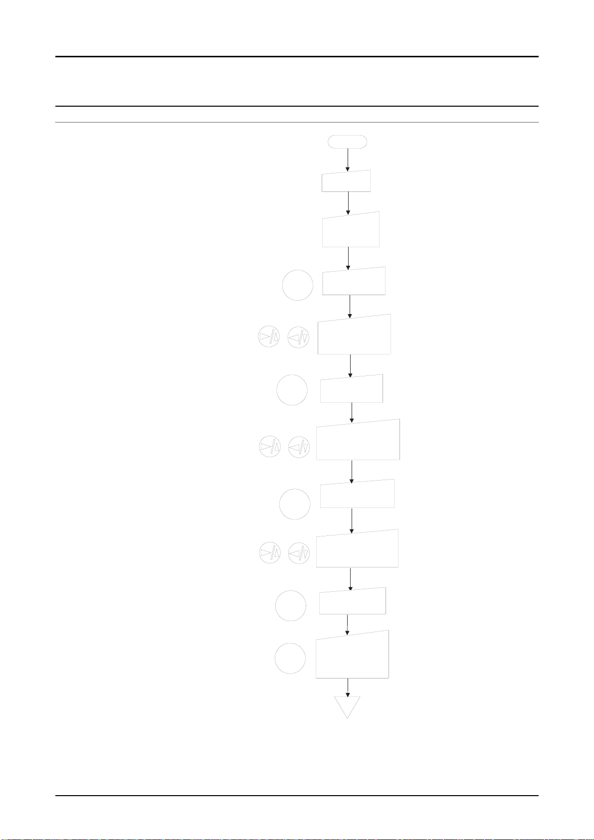
1.4.3.2 Photo Format Setting
ZOOM / PANORAMA / MULTI-FRAME
START
Pow er O N
View O FF P layback
View m ode O N .
Zoom
Zoom
Press the
photo form at
button.
Panoram a
M u lti.
P anoram a
P anoram a
Press the
photo form at
button.
Zoom
Panoram a
M u lti.
PhotoPC600
Chapter 1 Product Description
M u lti- fr a m e
Press the
photo form at
button.
Zoom
Panoram a
M u lti.
Zoom x1
Press
b u tto n
Zoom x 1.3 tim es
Press
b u tto n
Zoom x 1.6 tim es
Press
b u tto n
Zoom x 2.0 tim es
Press
b u tto n
Zoom x1
Press
b u tto n
Panoram a m ode
END
Zoom
Panoram a m ode
M ulti fram e m ode
Press
Zoom
b u tto n
Press
b u tto n
END
Zoom x 2.5 tim es
Press
b u tto n
Zoom x 3.0 tim es
END
Figure 1-7. Photo Format Shooting
Rev. A
1-1
Page 24
5
1.4.3.3 Macro Mode (Close Range Shooting)
PhotoPC600
Chapter 1 Product Description
CHECK POINT
üüüü
1. Turn the camera on and slide the monitor mode switch to View mode.
2. Press the macro button to enter the macro mode.
Note1)
3. Focus on the subject and check it on the LCD monitor. Then push the shutter button half
Note2)
4. Push the Shutter button until it stops completely.
At this time, a green frame appears around the previewed image on the LCD monitor
and Macro mark, which is represented by a flower mark, appears on the control panel.
in order to lock the auto focus.
Check that a green "O" mark appears on the right top of the monitor when checking
the subject by the LCD monitor, and the red status light turns into green when trying
to take a photo only by the viewfinder.
n
n
In the macro mode, the camera can approach to the subject up to
n n
maximum 20 cm. Release the macro mode, in case of taking a photo
further than 50 cm.
n
n
It is recommended to use the LCD monitor in the view mode rather
n n
than the viewfinder when taking a photo in macro mode. Otherwise,
the image you are seeing may not fit to the frame when you get
closer to the subject, looking at viewfinder.
n
n
Unlike the previous models; PhotoPC and PhotoPC500, taking a
n n
photo with wearing a close up lens is impossible
MONOCHROME MODE
CHECK POINT
üüüü
1. Turn the camera on and slide the monitor switch to View mode.
2. Press the image quality button two or three times until it sets monochrome mode(BW).
Note)
You can choose either Monochrome fine mode or Monochrome super-fine mode by
pressing the image quality button.
n
n
It is recommended to use the LCD monitor when taking a photo of
n n
documents at Monochrome modes.
Rev. A
1-1
Page 25
6
MULTI-FRAME SHOOTING TIME
PhotoPC600
Chapter 1 Product Description
CHECK POINT
üüüü
n
n
The shooting times; 0.5, 1, 2 or 3 which are displayed on the LCD
n n
monitor, are the seconds as the total shooting time and the nine
frames are taken in that seconds. The initial setting is set at 0.5 sec.
START
Power ON
Either View
mode or
Playback ON.
SELECT
Press the
SELECT button.
Select "Settings"
menu by using
navigation buttons.
This saves the setting
and returns to the
Setting menu.
At this time, the current
selection is highlighted.
SELECT
SELECT
BACK
BACK
Press the
SELECT button.
Select "Multiframe shooting
time" by the navigation buttons.
Press the SELECT
button to select the
shooting time.
(0.5,1.2, or 3 sec.)
Press the BACK
button after choosing
the shooting time.
Screen returns to
the Setting menu.
Press the BACK
button to go back
to the normal mode.
END
Figure 1-8. Multi-Frame Shooting Time
Rev. A
1-1
Page 26
7
SETTING THE ALERT BEEP; ON/OFF
PhotoPC600
Chapter 1 Product Description
START
Power ON
Either View
mode or
Playback ON.
SELECT
SELECT
SELECT
Press the
SELECT button.
Select "Settings"
menu by using
navigation buttons.
Press the
SELECT button.
Select the beep
setting icon by the
naviagation buttons.
Press the SELECT
button to select
ON or OFF.
This saves the setting
and returns to the
Setting menu.
At this time, the current
selection is highlighted.
BACK
BACK
Press the BACK
button after choosing
ON or OFF.
Screen returns to
the Setting menu.
Press the BACK
button to go back
to the normal mode.
END
Figure 1-9. Setting the Alert Beep
Rev. A
1-1
Page 27
8
1.4.3.4 Basic LCD Settings
SETTING LCD BRIGHTNESS
PhotoPC600
Chapter 1 Product Description
START
Power ON
Either View
mode or
Playback ON.
The mark on the
brightness setting
slide bar turns orange.
SELECT
SELECT
SELECT
Press the
SELECT button.
Select "Settings"
menu by using
navigation buttons.
Press the
SELECT button.
Select the brightness
icon by the
naviagation buttons.
Press the SELECT
button again.
Adjust the screen
brightness by the
navigations buttons.
This saves the setting
and returns to the
Setting menu.
BACK
BACK
Press the BACK
button.
Press the BACK
button twice to go
back to the normal
mode.
END
Figure 1-10. Setting the LCD Brightness
Rev. A
1-1
Page 28
9
SETTING THE INFORMATION DISPLAY
PhotoPC600
Chapter 1 Product Description
CHECK POINT
üüüü
n
n
During multi-photo play back mode, the information that are
n n
indicated on the normal play back mode, such as the image quality
setting, the number of photos you can take, and the number of
photos taken are not indicated
START
Power ON
Either View
mode or
Playback ON.
SELECT
Press the
SELECT button.
Select "information"
menu by using
navigation buttons.
Press the
Choosing ON is
for displaying
photo information
SELECT
SELECT button
to select ON or
OFF.
on the LCD screen.
Press the BACK
BACK
button to save the
setting.
END
Figure 1-11. Setting Information Display
Rev. A
1-1
Page 29
Chapter 1 Product Description
0
SETTING THE LANGUAGE
English, Japanese, French, German, Italian, Portuguese or Spanish is available.
START
Power O N
Turn the Playb a c k O N .
PhotoPC600
SELECT
SELECT
BACK
Press the
SE LEC T button.
Select "Language"
m enu by using
navigation buttons.
Press the
S E L E C T b u tto n
to s e le c t th e
language you w ant.
Press the BACK
b u tto n to s a v e th e
setting.
END
Figure 1-12. Setting the Language
Rev. A
1-2
Page 30
1.4.3.5 Setting the Playback Mode
NORMAL PLAYBACK MODE
PhotoPC600
Chapter 1 Product Description
CHECK POINT
üüüü
1. After turning the camera ON, Slide the monitor switch to Playback.
2. The last photo you took is displayed in the full size. Pressing the navigation buttons
allows you to see the next photo or the previous one.
MULTI-PHOTO PLAYBACK MODE
CHECK POINT
üüüü
1. After turning the camera ON, Slide the monitor switch to Playback.
2. The last photo you took is displayed in the full size.
3. Press the SELECT button. ("Setting" menu appears on the initial monitor)
4. Indicate the "Playback Mode Menu" by using the navigation buttons.
5. Every time you press the SELECT button, it switches between Normal and Multi-photo
Playback modes.
6. Press the BACK button to save your setting.
Note)
After selecting the photo to check by using the navigation buttons, the selected photo
can be full size by pressing the SELECT button twice. Also, at this time, you can
remove other unnecessary indications by pressing the BACK button.
n
n
Since the data is red from the internal memory of the camera during
n n
the playback mode, it is not influenced by ON and OFF of the main
power.
n
n
Once the multi-photo playback mode is confirmed, that mode is
n n
stored and it is not lost even after the power is turned off.
n
n
This setting need to be reset when batteries are replaced without
n n
using the AC adapter.
SLIDE SHOW MENU
CHECK POINT
üüüü
1. After turning the camera ON, Slide the monitor switch to Playback.
2. The last photo you took is displayed in the full size. (If the Multi-photo playback mode is
already set, 9-frame images appear)
3. Press the SELECT button. ("Setting" menu appears on the initial monitor)
4. Indicate the "Slide Show Menu" by using the navigation buttons.
5. Press the SELECT button. ("Slide show" is indicated on the top of the monitor for 3
seconds, and automatic playback starts)
6. Press the BACK button to stop the slide show and return to the normal Playback mode.
n
n
This mode automatically keeps playing back all the photos in the
n n
camera by one by until external operation is done.
n
n
During this mode, press the 3333/6666button to move back through the
n n
photos manually.
n
n
During this mode, press the 8888/5555button to move forward through the
n n
photos manually.
n
n
During this mode, pressing the SELECT button pauses the screen.
n n
(At this time, the pause icon and current picture count appear on the
bottom of the screen)Pressing the SELECT button again during this
pause, the rest of photos are played.
Rev. A
1-21
Page 31

PhotoPC600
2
Chapter 1 Product Description
1.4.3.6 Other Settings
LOCK / UNLOCK ALL PHOTOS
1. After turning the camera ON, Slide the monitor switch to Playback.
2. Press the SELECT button. ("Setting" menu appears on the initial monitor)
3. Indicate the "Photo Control Menu" by using the navigation buttons.
4. Press the SELECT button. (5 items for photo control menu are displayed)
5. Press the navigation buttons until "Lock" is highlighted in orange, and press the SELECT
button to enter the Lock mode.
6. 3 Lock menu items appear. Choose an item you want to perform by using the navigation
buttons. Then, press the SELECT button again.
[Select Lock/Unlock]
7. Select the photo you want to lock or unlock by using the navigation buttons. Press the
SELECT button, then a lock icon appears at the bottom of the screen, or disappear if it
was locked originally. If you want to lock or unlock other photos at the same time, use the
navigation buttons to display them, then press the SELECT button.
8. Press the BACK button after you have selected all the photos you want to lock or unlock.
A message appears asking you to confirm your selections.
9. *Press the SELECT button to lock or unlock the images and return to the "Photo Control
Menu". Press the BACK button to lock or unlock again, or cancel for locking or unlocking the
photos.
CAUTION
n
n
When the monitor is on the multi-photo mode, the operation method
n n
is the same except for operating 9 images at the same time.
n
n
*Among the lock items, if you select "Lock All" or "Unlock All" by the
n n
SELECT button, the rest of operation is the same as procedure 9
written above.
Rev. A
1-2
Page 32

3
ERASING PHOTOS
Erasing a selected
picture
START
Power ON
Playback
mode ON.
View OFF Playback
Erasing selected pictures
PhotoPC600
Chapter 1 Product Description
Erase All
Select a image to
erase by the
navigation buttons.
Press SELECT
button
Select "Erase Photo
Menu" by the navigation buttons.
Press SELECT
button
A message appears
to confirm the image
to erase.
SELECT: Erase
BACK :Cancel
Press BACK
button to return
to the Playback
mode.
END
SELECT
SELECT
SELECT
BACK
Repeat these steps
to select several
images.
Press SELECT
button
Select the "Photo
Control Menu" by
the navigation buttons.
Press SELECT
button
Photo Control Menu is
displayed.
Select "Erase" by
the navigation
buttons.
Press SELECT
button
Erase Menu is indicated
Choose "Select
Photo" by the
navigation buttons.
Press SELECT
button
The last Playback
screen is indicated
Select images to
erase by the navigation
buttons.
Press SELECT
button
An orange frame appears
around the image
SELECT
SELECT
SELECT
SELECT
SELECT
Press SELECT
button
Select the "Photo
Control Menu" by
the navigation buttons.
Press SELECT
button
Photo Control Menu is
displayed.
Select "Erase" by
the navigation
buttons.
Press SELECT
button
Erase Menu is indicated
Choose "Erase
All" by the
navigation buttons.
Press SELECT
button
A message appears
to confirm the image
to erase.
SELECT: Erase
BACK :Cancel
Press BACK
button to return
to the Playback
mode.
SELECT
SELECT
SELECT
SELECT
SELECT
BACK
BACK
SELECT
END
END
Press the
BACK button
Press SELECT
button
Figure 1-13. Erasing Photos
Rev. A
1-2
Page 33

4
MEMORY INFORMATION
PhotoPC600
Chapter 1 Product Description
START
Power ON
Playback ON
SELECT
SELECT
SELECT
Press the
SELECT button.
Select "Photo Control
Menu" by using
navigation buttons.
Press the SELECT
buttton to confirm
the "Photo Control
Menu".
Select "Memory
Info" by the
navigation button.
Press the
SELECT button.
Rev. A
Memory information
is indicated.
SELECT
Press the
SELECT button
3 times.
Normal mode
is indicated.
END
Figure 1-14. Getting Memory Information
1-2
Page 34

5
COPYING PHOTOS
PhotoPC600
Chapter 1 Product Description
CAUTION
n
n
This function is to copy photos between the camera's internal
n n
memory and the memory card.
n
n
Install or remove the memory flash card when the camera is turned
n n
off. If the memory card is installed or removed while the camera is
On, the internal data of images are all lost.
START
Power ON
Playback ON
Press the
SELECT
SELECT
SELECT button.
Select "Photo Control
Menu" by using
navigation buttons.
Press the SELECT
buttton to confirm
the "Photo Control
Menu".
SELECT
BACK
SELECT
END
Select "Copy" by
the navigation
buttons.
Press the
SELECT button.
Select the copy
destination by the
navigation buttons;
Camera Card or
Card Camera
Select photos to
copy.
Press the BACK
button to confirm
after the selection
is made.
Press the
SELECT button.
Press the
SELECT button
3 times.
Note) Procedure for selecting
photoes is the same as the one
of "Select Photo" in the Ersaing
photos.
SELECT
Figure 1-15. Copying Photos
Rev. A
1-2
Page 35

6
FORMATTING MEMORY CARD
PhotoPC600
Chapter 1 Product Description
CHECK POINT
üüüü
n
n
Since the EPSON Compact Flash Cards are already formatted in the
n n
factory, it is not necessary to perform this operation unless the
memory cards fall into the abnormal situations and become unable
to use without formatting.
START
Power ON
Playback ON
Press the
SELECT
SELECT button.
Select "Photo Control
Menu" by using
navigation buttons.
SELECT
SELECT
SELECT
BACK
Press the SELECT
buttton to confirm
the "Photo Control
Menu".
Select "Format
Card" by the
navigation buttons.
Press the
SELECT button.
A message appears stating
that all data on the card will
be erased and asking you
to confirm the procedure.
Press the
SELECT button
again.
Press the BACK
button three times.
This formats the card
and return to the "Photo
Control Menu".
END
Figure 1-16. Formatting the Memory Flash Card
Rev. A
1-2
Page 36

PhotoPC600
7
Chapter 1 Product Description
Rev. A
1-2
Page 37

CHAPTER
OPERATING PRINCIPLES
2
Page 38

PhotoPC600
Chapter 2 Operating Principles
2.1 OPERATING PRINCIPLES
Majority of the PhotoPC600 parts consists of the electric circuits boards. The figure below shows
those boards and explains their functions.
A. SY1 Board
B. LCD Monitor
C. CA1 Board
F. CA2 Board
E. ST1 Board
Front Side
D. TB1 Board
Figure 2-1. PhotoPC600 Board Locations
The Table below shows function of each board.
Table 2-1. Functions of Each Board
No. Name Function
A SY1 4-bit microprocessor as the central system is mounted on the back of this
board. User’s I/F control, Power supply/Stop control, STROBE
charge/discharge control, Clock control and back up for setting, and internal
communication bus control are handled here.
B LCD 1-unit of electric part combined with LCD monitor and light. RGB signal to take
the actual image is controlled from the CA2 board.
C CA1 CCD is soldered directly. This board has H/V driver in order to drive the CCD,
CDS/AGC circuit to correct the image, and A/D converter circuit to transfer the
data to the internal ASIC. Also, the lens unit with AF(auto focus) function is
mounted on the board and automatically adjusts the focus by operating light
that the CCD receives.
D TB1 Small board mounted with a switch for photo modes.
E ST1 Unlike the PhotoPC and PhotoPC500, this board only generates power supply
for the LCD monitor, and digital and analog. Flash is also installed and also an
electrolytic capacitor with large capacity in order to emit light. (Careful attention
is necessary to handle this capacitor) This board also has connectors for AC
adapter and for video output.
F CA2 This board has LCD monitor control, option memory flash card control, and
also works as the internal central system for the photographic processing.
CAUTION
Rev. A
n
n ST1 board has a danger of electric shock because of C5412.
n n
Hold the edges of this board and Never touch the board surface
when you handle this board.
n
n Discharge the charged energy of C5412 for safety before handling
n n
this board. (Refer to Chapter4)
2-1
Page 39

Chapter 2 Operating Principles
2
2.1.1 Out line of Operating Principles
The following figure shows the block diagram about overall operation by PhtoPC600.
Next pages simply explain operation of each board.
Subject
Lens
Optical
Filter
CCD
CDS/AGC
PhotoPC600
RISK
CPU
Flash
control
Circuit
ST1 Board
DC/DC
Conv.
A/D
10bit
CA1Board
AC Adapter
DRAM
Address Bus
Data Bus
Scan
Convertor
ST SG
Output Circuit
DMA Control
Circuit
PC
Option Flash
Memory Card
RS-232C
9-pin Din
Function SW
Signal arithmetic Circuit
4M Flash
(x4)
Power SW
Shutter SW
UART
Driver
NTSC
Encoder
af/ae/awb
Integrator
Buzzer
PIO
LCD
Driver
4bit
CPU
TV
Monitor
LCD Moitor
CA2 Board
SY1 Board
3.3V
regutrater
AA-size Batteries
Figure 2-2. Block Diagram for Overall Operation
Rev. A
2-
Page 40

PhotoPC600
3
Chapter 2 Operating Principles
CA1 BOARD
The following are the major ICs on the CA1 board. Starting from driving the CCD, they perform
processing and A/D conversion until image data is transformed to the internal system.
Table 2-2. Major Components of the CA1 Board
No. Location Parts Name Function
1 IC903 ICX081AK CCD imager
2 IC902 TC74VHC04 H-Driver, Clock for horizontal data transfer in order to
drive CCD
3 IC904 CXD1267AN V-Driver, Clock for horizontal data transfer in order to
drive CCD
4 IC905 CXA2006Q CDS, AGC circuit
5 IC906 CXD2311AR A/D converter IC for internal system transfer
CA2 BOARD
The Table below shows major circuits on the CA2 board.
Table 2-3. Various Control Circuits of the CA2 Board
No. Circuit Name Function
1 Scan converter This is the circuit that converts CCD output signal to the interlace
signal for TV.
2 Signal Processor
3 Digital clamp This circuit compares the optical black section of the CCD and
4 White balance The circuit controls the white balance by using the AWN judgment
5
g
6 Color signal
generation
7 Matrix This circuit generates Y, R-Y and B-Y signals from RGB signal.
8 Horizontal
Aperture
9 DRAM controller This circuit controls RAS and CAS and outputs Refresh signal.
10 UART This circuit transfers the image data to PC on the basis of RS-232C.
11 PIO This is the interface circuit for the 4-bit microprocessor on the SY1
12
TG · SG
13 LCD driver Y/C signal, which is input to this signal, is converted to RGB signal
14 LCD monitor LCD monitor
Generic name of No.3~No.8 circuits below.
image data and makes the black level of the CCD output data
uniform for each line.
value computed by the CPU to control the gain for each R, G and B
pixel based on the CCD data which has been read.
This circuit performs correction in order to maintain a linear
relationship between the light input to the camera and the light
output from the picture screen.
This circuit converts CCD signal to RGB signal.
This circuit generates aperture signal.
board.
This is the generation circuit which generate the vertical data
transfer clock and electric shutter clock.
and synchronized to CLK signal, and is transferred to the LCD.
Rev. A
2-
Page 41

PhotoPC600
4
Chapter 2 Operating Principles
ST1 BOARD
ST1 board can be divided into 2 blocks; power supply circuit part and strobe control circuit part.
Following explains each part.
Table 2-4. ST1 Board (Electric Block)
No. Location Function
1 IC311 This has a PWM-type switching regulator circuit with 6 channels.
Output voltage is;
1) Power supply voltage for LCD 5 V(L), 12 V(L), 15.5V(L)
2) Digital power supply voltage 5 V(D), 3.4 V(D)
3) Analog power supply voltage 5 V(A), 12 V(A), -6.5 V(A)
There are two safety circuits on this regulator;
1) Short-circuit protection circuit
2) Mis-operation prevention circuit for cases of low input voltage
2 T3101 Pressure rise/fall transformer for Analog output voltage
3 T3103 Pressure rise transformer for LCD drive voltage output
There are two parts of circuits in the strobe control circuit part; charge circuit parts and light
emission circuit. They are described below.
Table 2-5. ST1 Board (Strobe Control Block)
No. Circuit Name Function
1 Charge circuit When the flash is emitted during the Forced or Auto flash, CHG
signal is output high from the SY1 board and charges the main
electrolytic capacitor into high voltage direct current.
Charge circuit consists of mainly following 5 circuits.
1) Power supply filter It smooth out ripples in the current
which accompany the switching of
the oscillation transformer and LC
circuit composition.
2) Oscillation control Outputs a drive pulse with a
frequency of 15 K Hz to increase
DC voltage.
3) Oscillation transformer Converts the low voltage alternating
current to a high-voltage alternating
current by this transformer.
4) Rectifier Converts the high-voltage
alternating current to a high voltage
direct current.
5) Voltage monitoring Monitors the voltage level of C5412.
Detects full charge by 2.7 V DC.
2 Light emission
circuit
Strobe emits light when SDY and TRIG signals are input to from
ASIC. Emission circuit consists of mainly the following 3 circuits;
1) Emission control circuit part When the RDY signal is
input to this circuit, Q5409
which is the main source of
the emission current, is
turned on.
2) Trigger circuit D5405 is turned on with
input of TRIG signal.
3) Light emitting element Light is emitted when the
high-voltage pulse is applied
to the light emitting part.
Rev. A
2-
Page 42

PhotoPC600
5
Chapter 2 Operating Principles
SY1 BOARD
SY1 board had 4-bit microprocessor and handles the following the functions.
Table 2-6. Various Circuits of the SY1 Board
No. Circuit Name Function
1 Charge Outputs /CHG On signal to the ST1 board. Also, this circuit monitors
the value of partial pressure of C5412 and controls to stop charging.
Also, it judges if the power supply is AC adapter or battery and
changes the complete time of the battery charge. This prevents the
AC adapter from being heat up.
2 LCD light on Control On/Off of LCD back light. However, characters for explanation
on the LCD are transferred by internal ASIC on CA2 board.
3 Cable Detection When RS-232C cable is installed, this circuit makes all button
functions on the camera invalid.
4 CPU
Communication
5 Power supply
control
6 Battery life
monitor
7 Video terminal
monitor
8 Card installation
monitor
9 Buzzer control On/Off control of buzzer drive.
10 LCD panel
control
11 LED control Controls all 3 LED drives.
Perform serial communication with internal main CPU(SPARC).
Outputs two wake up signals in order to generate power supply for
digital and analog individually.
Monitors the AA-size battery life at the voltage level.
Monitors if the cable for the video output is installed or not.
When the power is on, this circuits reads empty raster and calculates
how many pictures can be taken after detecting the existence of the
compact flash card. Also, after the card detection, internal
memory(4M) is invalid.
Controls the present settings and indication of available photos to take
by the key matrix.
TB1 BOARD
TB1 board is a small board which is mounted with a push button to change over photo
format(modes); Zoom, Panorama, and Multi-frame. The signal to check the button condition is
output periodically from 8-bit CPU on the SY1 board, and mode is changed by recognizing the
change of the button condition.
Rev. A
2-
Page 43

TROUBLESHOOTING
CHAPTER
3
Page 44

PhotoPC600
Chapter3 Troubleshooting
3.1 OVERVIEW
PhotoPC600 does not have a function to display errors by LCD or LED. Also, it is difficult to find
malfunction parts from the symptoms. Therefore, check each check points according to the
procedures in this chapter and perform proper repair service.
WARNING
CAUTION
No. Service Performed Required Adjustment Maintenance
1 Replacing CA1 Board 1) Initialization
2 Replacing the CA2 Board 1) Initialization
3 Replacing the LCD
monitor
4 Replacing the SY1 Board Not required 1st Maintenance
5 Replacing the ST1 Board Not required 1st Maintenance
6 Replacing the TB1 Board Not required 1st Maintenance
n
n Disconnect the AC adapter or batteries before disassembling the
n n
camera.
n
n Discharge the electricity in the electrolytic capacitor by using cement
n n
resistor when you need to touch the ST1 board for repair service.
(See Chapter 4 , page 4-4 for more details) The electrolytic
capacitor(C5412), which is mounted on the ST1 board is for light
emission and to be charged automatically every time the power is
turned on. Therefore, there is a danger of getting electric shock.
n
n In this products, there are 2 repair levels; first maintenance and
n n
second maintenance. The performance of the second maintenance is
allowed to be done only by EPSON Co., Ltd. We do not guarantee the
repair result by the others. Refer to Table below for distinction
between first and second maintenance.
Table 3-1. Criterion of First/Second Maintenance
2nd Maintenance
2) 5100K AWB adjustment
3) Flange-back adjustment
2nd Maintenance
2) 5100K AWB adjustment
3) Flange-back adjustment
4) LCD H AFC adjustment
5) LCD RGB Off Set adjustment
6) LCD Gain adjustment
7) LCD Blue Brightness adjustment
8) LCD Red Brightness adjustment
1) LCD H AFC adjustment
2) LCD RGB Off Set adjustment
3) LCD Gain adjustment
4) LCD Blue Brightness adjustment
5) LCD Red Brightness adjustment
2nd Maintenance
Rev. A
3-1
Page 45

PhotoPC600
2
Chapter3 Troubleshooting
3.1.1 The camera has no power
This section describes check points and solution when LCD is not indicated or red LED light keeps
blinking and does not go to the waiting mode after turning the power switch (rotary switch) on with
batteries or AC adapter. Refer to Tables 3-2~3-4 below.
CHECK POINT
üüüü
n
n If something abnormal occur to 8-bit CPU, which is located under
n n
SY1 board and in charge of controlling user’s I/F, the order signal to
generate digital and analog power for various functions can not be
output. And as a result, the camera falls into no power error. Also,
since this 8-bit CPU communicate with main CPU on the CA2 board,
the same symptom appears when something happens on the CA2
board too.
Table 3-2. Check points when the Camera has no power
Step Checkpoint Solution
1 Is CN303 of SY1 disconnected? Connect CN303 again.
2 When turning the power switch (rotary switch) on and off,
does the micro-switch also really turn on and off,
corresponding to power switch?
3 Is there continuity in the cables(2-pin, red and black) for
micro-switch?
4 Is CN301 of SY1 connected to CN106 of CA2 board? Push SY1 board into
5 Is CN311 of ST1 board connected to CN104 of CA2
board?
6 Is the connector between CN314 of ST1 board and CN305
of SY1 board secured steady?
7 Does each fuse(F3102, F3103) on the both sides of ST1
board has continuity?
8 Is SY1 board defective? Replace SY1 board.
9 Is CA2 board detective? Replace CA2 board.
10 Is ST1 board defective? Replace ST1 board.
Install a micro-switch
again.
Replace the cable.
CA2 board.
Push ST1 board into
CA2 board.
Secure either one of
connectors.
Replace either one of
fuses.
Table 3-3. Check points when the Camera has no power with batteries
Step Check point Solution
1 Is the battery cover fixed steady between the front cabinet
and rear cabinet?
2 Are 2 peaking points for installing the battery cover broken
or damaged?
3 Is the insulating film around the battery blocking electric
poles, because of defective battery?
4 Are there any foreign objects on or around electric poles,
such as remaining of plastic package of battery?
5 Are electric poles for battery located under the SY1 board
worn out?
Table 3-4. Check point when the batteries overheat in only using AC adapter
Step Check Point Solution
1 Is the user using recommended AC adapter or other kind
of adapter?
2 Is the DC Jack in the DC inlet on the ST1 board defective? Replace ST1 board.
Install the battery cover
again.
Replace the battery
cover.
Replace batteries.
Eliminate the foreign
objects.
Replace SY1 board or
correct the angle of
electric poles by hand.
Use the recommended
adapter only.
Rev. A
3-
Page 46

PhotoPC600
3
Chapter3 Troubleshooting
3.1.2 Red LED Light Blinking
This section shows check points and solution when LED light next to lens viewfinder keeps
blinking and does not indicate waiting mode(green light). Refer to Table3-5 below.
CHECK POINT
üüüü
Step Check Point Solution
1 Is CN301 of SY1 board connected to CN106 of
CA2 board?
2 Is SY1 board defective? Replace SY1 board.
3 Is CA2 board defective? Replace CA2 board.
n
n If red LED light does not stop blinking, it means that 8-bit CPU on the
n n
SY1 board is not communicating well with main CPU on the CA2
board.
Table 3-5. Check points when red LED light blinking
Push SY1 board into CA2
board.
3.1.3 Shutter does not work
Here shows check points and solution when the image data can not be taken or the beep sound of
buzzer does not work even it is set On. Refer to Table3-6 below.
Table 3-6. Check point when the shutter button does not work
Step Check Point Solution
1 Remove the top cover and see if the peaking
located back of the shutter is broken or not.
2 Is S3029 micro-switch on the SY1 board broken? Replace SY1 board.
3 Is the power supply block on the ST1 board
defective?
Replace the shutter button.
Replace ST1 board.
3.1.4 Image is taken out of cross mark in the viewfinder
(Not using LCD monitor)
Here shows check points and solution when the images are taken out of central cross mark in
using the lens viewfinder. Refer to Table3-7 below.
Table 3-7. Check points when image is taken out of cross mark in the viewfinder
Step Check Point Solution
1 Is the user trying to take a picture within 50cm
to the subject without using Macro mode?
2 Is the lens viewfinder installed on the holder
chassis correctly?
3 Is holder chassis connected to CA1 board
correctly?
4 Is soldering CCD on the CA1 board done
correctly?
Rev. A
Advise the user to use Macro
mode.
Install the lens viewfinder
correctly.
Connect the holder chassis
correctly.
Solder CCD correctly.
3-
Page 47

PhotoPC600
4
Chapter3 Troubleshooting
3.1.5 Nothing appears on the Camera and Computer screens (All black)
Here shows check points and solutions when the LCD screen(or computer screen in case of
transferring image data to the computer) is all black even in the Playback mode or View mode
after taking pictures.
CHECK POINT
üüüü
Step Check Point Solution
1 Is CA2 board defective? Replace CA2 board.
2 Is CA1 board defective? Replace CA1 board.
3 Is CCD defective? Replace CCD.
n
n Even when the CCD is broken and unable to take images, the camera
n n
still operates regularly.
n
n Judging from repair experiences of PhotoPC and PhotoPC500, many
n n
cases of this kind of troubles are due to the dropped and broken
main control boards by the users rather than accidental malfunction
around CCD.
Table 3-8. Check points when nothing appears on the screen
3.1.6 Unable to transfer image data to PC
This section shows check points and solution when the image data can not be transferred from the
camera to PC.
Table 3-9. Check points when image data can not be transferred to PC
Step Check Point Solution
1 Is the user using PC with Max.
communication speed 9600bps?
2 See if the cable terminal on the camera
side is damaged or not , and check if there
is any broken iron piece in the connector
hole or not.
3 Refer to the cable connection in the
Appendix and check if there is continuity in
the serial cable.
4 Is ST1 board defective? Replace ST1 board.
Use high-speed serial I/F board.
Replace ST1 board.
Replace the cable.
Rev. A
3-
Page 48

PhotoPC600
5
Chapter3 Troubleshooting
3.1.7 No images on the LCD screen
This section shows check points and solution when images does not appear only on the LCD
screen even when images can be transferred to PC all right.
Table 3-10. Check points when no images on the LCD screen
Step Check Point Solution
1 Is the connector(white) of LCD monitor
inserted to CN315(white) on the ST1
board?
2 Is FPC of LCD monitor inserted to
CN171(brown) on the CA2 board ?
3 Is CN315 on the ST1 board soldered
steady?
4 Is CN171 on the ST1 board soldered
steady?
5 Is LCD monitor defective? Replace LCD monitor.
Insert the connector to CN315
steady.
Insert FPC to CN171 steady.
Replace ST1 board.
Replace ST1 board.
3.1.8 Unable to use optional Compact Flash Card
This section shows check points and solution when the number of pictures you can take does not
change after installing optional Compact Flash Card, or image data can not be red even after
removing the Flash card and connecting to PC or another camera.
Table 3-11. Check points when unable to use the flash card
Step Check Point Solution
1 Is all 50-pin of CN141 on the CA2 board
damaged?
2 Doesn’t the user insert or remove the
flash card when the power is still on?
3 Is the compact flash card itself
defective?
Replace CA2 board.
Give them right instruction.
Replace the Compact Flash
Card.
3.1.9 Picture is blurry or out of focus
Table 3-12. Check points when picture is out of focus
Step Check Point Solution
1 The focus adjustment value stored in
the memory is not correct.
2 Is the lens unit defective? Replace the lens unit.
3 Is CA2 board defective? Replace CA2 board.
Refer to Chapter5 and perform
Flange-back adjustment.
Rev. A
3-
Page 49

CHAPTER
4
DISASSEMBLY AND ASSEMBLY
Page 50

PhotoPC 600
Chapter4 Disassembly and Assembly
4.1 OVERVIEW
This section describes disassembly and assembly of major components of PhotoPC600. Since the
assembly process is relatively complicated, procedures for disassembly and assembly are
explained individually.
4.1.1 Precautions
See the precautions below before disassembling and assembling PhotoPC600.
WARNING
CAUTION
No. Service Performed Required Adjustment Maintenance
1 Replacing CA1 Board 1) Initialization
2 Replacing the CA2 Board 1) Initialization
3 Replacing the LCD
monitor
4 Replacing the SY1 Board Not required 1st Maintenance
5 Replacing the ST1 Board Not required 1st Maintenance
6 Replacing the TB1 Board Not required 1st Maintenance
n
n Disconnect the AC adapter or batteries before disassembling the
n n
camera.
n
n Discharge the electricity in the electrolytic capacitor by using cement
n n
resistor when you need to touch the ST1 board for repair service.
(See page 4-4 for more details)The electrolytic capacitor(C5412),
which is mounted on the ST1 board is for light emission and
arranged to be charged automatically every time the power is turned
on. Therefore, there is a danger of getting electric shock.
n
n In this products, there are 2 repair levels; first maintenance and
n n
second maintenance. The performance of the second maintenance is
allowed to be done only by EPSON Co., Ltd. We do not guarantee the
repair result by the others. Refer to Table below for distinction
between first and second maintenance.
n
n Refer to section 4.1.5 for assembly.
n n
n
n Use the exclusive package material when transporting cameras.
n n
Table 4-1. Criterion of First/2nd Maintenance
2nd Maintenance
2) 5100K AWB adjustment
3) Flange-back adjustment
2nd Maintenance
2) 5100K AWB adjustment
3) Flange-back adjustment
4) LCD H AFC adjustment
5) LCD RGB Off Set adjustment
6) LCD Gain adjustment
7) LCD Blue Brightness adjustment
8) LCD Red Brightness adjustment
1) LCD H AFC adjustment
2) LCD RGB Off Set adjustment
3) LCD Gain adjustment
4) LCD Blue Brightness adjustment
5) LCD Red Brightness adjustment
2nd Maintenance
Rev. A
4-1
Page 51

PhotoPC 600
2
Chapter4 Disassembly and Assembly
4.1.2 Tools
The table below shows the tools recommended for repair service of PhotoPC600.
Table 4-2. Recommended Tools
No. Name Purchasable Code
1 5100 Kelvin color Viewer X 103058400
2 DscCal52 adjustment program X Attached with this manual book.
3 Simens star chart X Included in the end of this book.
4 Precision Driver (+) O ---5 Soldering iron O B740200100
6 Tweezers O B641000100
7 Oscilloscope O --8 Windows95 (require 19200bps or
O ---
higher for serial)
Note):
O means commercially available and X means not
.
4.1.3 Specification for Screws
Figure below shows the abbreviation of screws and its use.
Type of head
Type of threaded
section
Diameter
Length(L)
Configuration (Color)
100
101
102
103
L
(Black)
(Silver)
(Gold)
(Gold)
Abbreviation Part Name Shape
Abbreviation Part Name
Dimension
(mm)
Pan Head
Biding Head
Shape
No symbol Machine Screw
Forming Tight
(For plastic)
Forming Tight
(For metal)
Location
Most of PhotoPC-600
parts are fixed by this screws.
Exterior silver case and cover are
fixed by these 5 screws.
CA1 board and LCD holder are
fixed by these 2 screws.
Lens, spacer (iron)and CA1 board
are fixed by this screw.
104
(Gold)
Lens unit is fixed on the CA1 board
by these 2 screws.
Figure 4-1. Screw Identification
Rev. A
4-
Page 52

3
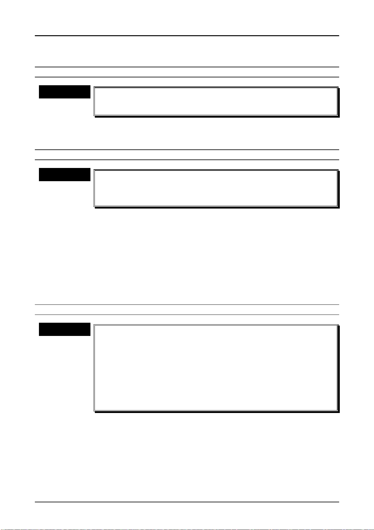
4.1.4 Procedure for Disassembly
The following shows the flow chart of the assembly.
PhotoPC 600
Chapter4 Disassembly and Assembly
CAUTION
n
n Refer to section 4.1.1 for precaution before starting disassembly.
n n
n
n Follow the numbers in the figure as the disassembly order.
n n
n
n Remove 7 cables for prevention of radiation(electric noise),
n n
according to your necessity. Also, refer to section 4.1.5 “Procedure
for Assembly” for soldering points during assembly.
Page4-4
R em ove the C abinet A ssem bly(R ear/Front), Top C over
and Battery C over.
Page4-5
R em ove SY 1 Board, S T1 B oard and B attery H older.
Page4-6
Rem ove the CA1 Board, LCD M onitor, CCD, CA2 Board,
View finder and LC D H older.
T o ta l
Assem bly
Figure 4-2. Flow Chart of Disassembly
Rev. A
4-
Page 53

PhotoPC 600
4
Chapter4 Disassembly and Assembly
4.1.4.1 Removing the Cabinet Parts
The figure below shows disassembling of Cabinet Assembly (Rear and Front), Top Cover and
Battery Cover.
1. Screw 2x5
(#100)
Grip
11. Remove the top cover.
10. Screw 2x5
(#100)
9. Remove a connector
for power supply.
4. Screw 2x5
(#101)
8. Remove the FPC.
5. Open this cover
by pressing the lever for
the card.
Figure 4-3. Procedure for Disassembly (1)
7. Remove a connector
for TB1.
6. Screw 2x5
(#100)
2. Open the cover.
WARNING
There is a danger of getting electric shock from the electrolytic
capacitor(C5412) mounted on the ST1 board. Discharge the electricity
by using the cement resistor when you need to touch the ST1 Board for
repair service. (See the figure below for details.)
CAUTION
Be careful not to damage the hook inside of grip when you remove the
top cover at “11” in the figure above. Also, pay attention not to scratch
the grip surface by that hook.
Avoid getting electric
shock by using insulating tape.
N o fix e d
direction
U se the resistance at least
560 ohm s/10W .
Figure 4-4. Discharging Electricity
C 5412
ST1 B oard
Rev. A
4-
Page 54

Chapter4 Disassembly and Assembly
5
4.1.4.2 Removing SY1 Board and ST1 Board
The figure below shows disassembly of SY1, ST1 Boards and Battery Holder.
PhotoPC 600
WARNING
CHECK POINT
üüüü
3. Remove a connector
from CA2 Board.
2. Remove a connector
from ST1 Board
There is a danger of getting electric shock from the electrolytic
capacitor(C5412). Therefore, discharge electricity from ST1 Board,
referring to section 4.1.4.1 before you start this section.
n
n The procedure for removing the cables for prevention of radiation
n n
(electric noise) is not explained here. Therefore, refer to section 4.1.5
“Procedure for Assembly” when assembling and perform soldering
of cable parts accurately. The cables for prevention of radiation
come out of the following 2 boards.(Total 7 cables)
*SY1 Board: 2 blue cables
*CA2 Board: 2 white cables, 2 black cables and one blue cable
1. Screw 2x5
(#100)
8. Release two
hooks.
11. Remove the
battery holder.
10. Screw 2x5
(#100)
5. Screw 2x5
(#100)
9. Remove the ST1
Board.
Figure 4-5. Procedure for Disassembly (2)
7. Remove a connector
with ST1 Board.
4. Screw 2x5
(#100)
6. Remove a connector
with ST1 Board.
Rev. A
4-
Page 55

PhotoPC 600
6
Chapter4 Disassembly and Assembly
4.1.4.3 Removing CA1 Board, CA2 Board, LCD and CCD
The figure below shows disassembly of CA1, CA2 boards, Lens viewfinder, LCD and CCD.
ADJUSTMENT
CHECK POINT
üüüü
9. Screw 2x4
(#102)
n
n When replacing CA1 Board or CCD, perform the following
n n
adjustments, referring to Chapter 5; 1)Initialization, 2)5100K AWB
adjustment, and 3)Flange-back adjustment.
n
n When replacing CA2 Board or LCD, perform the following
n n
adjustments, referring to Chapter 5; 1)Initialization, 2)5100K AWB
adjustment, and 3)Flange-back adjustment, 4)LCD H AFC adjustment,
5)LCD RGB Off set adjustment, 6)LCD Gain adjustment, 7)LCD Blue
Brightness adjustment, and 8)LCD Red Brightness adjustment.
n
n When assembling the optical filter, Refer to section 4.1.5 “Procedure
n n
for Assembly, since it has a determined direction to be installed.
14. Remove LCD from the
12. Remove FPC
from CA2 Board.
13. Release 2 at one side
out of 4 hooks.
CCD
Dampter
Optical filter
holder.
10. Remove a connector
from CA2 Board.
1. Screw 2x4
(#103)
2. Screw 2x6
(#104)
8. Screw 2x5
(#100)
6. Screw 2x5
(#100)
7. Remove the Lens viewfinder.
3. Screw 2x5
(#100)
4. Screw 2x5
(#100)
11. Release the lock
of FPC connector.
5. Remove the Holder
chassis.
Figure 4-6. Procedure for Disassembly (3)
Rev. A
4-
Page 56

PhotoPC 600
7
Chapter4 Disassembly and Assembly
4.1.5 Procedure for Assembly
Since PhotopC600 has rather complicated assembly process than disassembly process,
disassembly and assembly process are separated and explained individually. This section
describes assembly procedure.
ADJUSTMENT
n
n Refer to Table 4-1 and perform the proper adjustment after replacing
n n
and assembling the corresponding units or pats. Also, the
performance of the second maintenance is allowed to be done only
by EPSON Co., Ltd.
Section 4.1.5.1
Installing parts to the Front Cabinet.
Section 4.1.5.2
Installing parts to the Rear Cabinet.
Section 4.1.5.3
Connecting the Holder Chassis and Lens Viewfinder.
Section 4.1.5.4
Installing CCD and Lens Unit to the CA1 Board.
Section 4.1.5.5
Connecting CA1 Board and CA2 Board.
Section 4.1.5.6
Connecting Holder Chassis and CA1 Board.
Section 4.1.5.7
Connecting LCD Monitor and LCD Holder.
Section 4.1.5.8
Connecting LCD Holder and CA2 Board.
Section 4.1.5.9
Connecting ST1 Board and CA2 Board.
Section 4.1.5.10
Connecting SY1 Board and CA2 Board.
Section 4.1.5.11
Installing the Top Cover and Front Cabinet.
Section 4.1.5.12
Installing the Rear Cabinet and Battery Cover.
Refer to the Table 4-1 and Perform corresponding adjustments.
Figure 4-7. Flow Chart for Assembly
Rev. A
4-
Page 57

PhotoPC 600
8
Chapter4 Disassembly and Assembly
4.1.5.1 Installing the parts to the Front Cabinet
This section explains procedure of installing various parts to the front cabinet.
Refer to the following procedure and figures on the next page.
INSTALLING THE SPACER RING
Step1. Out of 2 hooks of the spacer ring, Hang only the upper hook to the front cabinet.
(Refer to the figure 4-8)
Step2. Rotate the upper hook, which is hung to the front cabinet at the Step1, to the left
edge, so that the lower hook appears around the front cabinet’s fixed part.
(Refer to the figure 4-9)
Step3. Push the bottom side of the spacer ring into the side of front cabinet and fix the
lower hook to the front cabinet.
(Refer to the figure 4-10)
Rev. A
4-
Page 58

Chapter4 Disassembly and Assembly
9
(Upper) Hook
Figure 4-8. Installing the Spacer Ring (1)
Rotate the hook
PhotoPC 600
Figure 4-9. Installing the Spacer Ring (2)
Push the (lower) hook from the front side of
the cabinet.
Figure 4-10. Installing the Spacer Ring (3)
Rev. A
4-
Page 59

PhotoPC 600
0
Chapter4 Disassembly and Assembly
ASSEMBLY OF SHUTTER MECHANISM (REFER TO FIGURE4-11)
Step4. Pierce the tension spring to the dimple for determining position. At this time, the
peaking point of the tension spring should be towards you. Then, fix it with
a screw 2x4(Black).
Step5. Put the peaking of the spacer ring to the hole of the cover lens. A.
Step6. Put the peaking of the spacer ring to the hole of the cover lens. B.
CHECK POINT
üüüü
Step7. Put the lever ring to the peaking of the spacer ring.
CHECK POINT
üüüü
Step8. Put the holder ring over and adjust position so that 3 screw holes match to 3 holes
INSTALLING THE POWER SUPPLY ON/OFF SENSOR (REFER TO FIGURE4-12)
Step9. Leave the power supply(spacer ring) Off.
Step10. Fix the power supply sensor with one screw 2x5(#100), referring to the figure4-12.
CHECK POINT
üüüü
n
n At this time, Leave the shutter closed with the cover lens A and B.
n n
n
n At this time, Install the lever ring as if the 2 peaking points of the
n n
lever ring wrap the cover lens A and B.
of the spacer ring. Then fix them with 3 screws 2x5(#100).
n
n Locate black and red cables so that a dimple for insulation comes
n n
between these two cables in order to avoid two cables getting short.
Rev. A
4-1
Page 60

Step4
C over Lens. A
Tension S pring
Screw 2x4(B lack)
Step5
PhotoPC 600
Chapter4 Disassembly and Assembly
Front C abinet
Step8
Screw 2x5
(#100)
Holder Ring
2 Peaking Points
Step7
Step6
Lever R ing
Figure 4-11. Assembly of the Shutter Mechanism
C over Lens. B
Rev. A
D im p le fo r in s u la tio n
P ow erS upply
O n/O ff S ensor
Screw 2x5
(#100)
Figure 4-12. Installing the Power Supply On/Off Sensor
4-11
Page 61

Chapter4 Disassembly and Assembly
2
INSTALLING THE COVER GRIP (FIGURE 4-13)
Step11. Fix the cover grip to the front cabinet with 2 screws 2x5(#100).
PhotoPC 600
Rev. A
4-1
Page 62

Chapter4 Disassembly and Assembly
3
Cover Grip
Screws 2x5
(#100)
Figure 4-13. Installing the Cover Grip
PhotoPC 600
Rev. A
4-1
Page 63

PhotoPC 600
4
Chapter4 Disassembly and Assembly
4.1.5.2 Installing the parts to the Rear Cabinet
This section explains installation of various parts to the rear cabinet.
INSTALLING TB1 BOARD (REFER TO FIGURE4-14)
Step1. Fix the TB1 board to the rear cabinet with 2 screws 2x4(#103).
INSTALLING LCD PROTECTION BOARD AND VIEWFINDER (REFER TO FIGURE4-15)
Step2. Refer to figure 4-15 and attach each adhesive parts to the specified area
accurately.
CAUTION
INSTALLING THE COVER JACK AND LCD SWITCH (REFER TO FIGURE4-16)
Step3. Install the cover jack and LCD SW (monitor mode switch) from the outside of the
CAUTION
n
n Unlike the completed camera, these spare parts have protection
n n
sheets, like stickers. Peel off those sheets before sending back
products to the customers.
n
n When attaching these parts to the rear cabinet, pay attention not to
n n
dislocate them.
rear cabinet.
n
n After temporary installing the cover jack, 5 dimples to fix the cover
n n
jack can be secured by pulling the cover jack from rear cabinet
inside.
n
n LCD SW (monitor mode SW) has a certain direction to be attached.
n n
Refer to Figure4-16 and pay attention not to install it in the wrong
direction.
Rev. A
4-1
Page 64

Chapter4 Disassembly and Assembly
5
TB1 Board
Figure 4-14. Installing TB1 Board
PhotoPC 600
Screws 2x4(#103)
Viewfinder
LCD Protection Board
Figure 4-15. Installing the Protection Board and Viewfinder
Check the direction to attach
from side of switch.
Figure 4-16. Installing the Cover Jack and LCD SW
Rev. A
4-1
Page 65

PhotoPC 600
6
Chapter4 Disassembly and Assembly
INSTALLING COVER JACK AND LCD SW (CON.) (REFER TO FIGURE4-17)
Step4. Reverse the rear cabinet so that you can see back of the cabinet and install the
slide monitor for fixing the LCD SW.
CAUTION
INSTALLING THE COVER GRIP BACK (REFER TO FIGURE4-18)
Step5. Put the FPC cable coming out of the control panel through the hole(A) as you can
Step6. Peel the sticker of the back of control panel unit and attach it to the cover grip back.
CAUTION
Step7. Install the strap holder to the cover grip back.
Step8. Fix the stand under the cover grip back temporally.
CAUTION
Step9. Fix the cover grip back to the rear cabinet with 2 screws 2x5(#100).
Slide Monitor has a determined direction to be attached. Refer to
figure4-17 and push in the LCD SW so that peaking point comes right
side.
see in the figure 4-18.
n
n When attaching the control panel unit, be careful not to dislocate it.
n n
n
n Do not fold the FPC coming out of the control panel unit.
n n
The stand has a determined direction to be attached. If the stand is not
fixed correctly at Step8, rotate its direction 180 degree.
Rev. A
4-1
Page 66

Chapter4 Disassembly and Assembly
7
LCD SW
Slide monitor
Slide monitor
Figure 4-17. Installing the Slide Monitor
PhotoPC 600
Back Side of Cover Grip Back
Step 9
Screw 2x5
(#100)
FPC Cable
Step 5,6
Hole (A)
Cover Grip Back
Step 7
Strap Holder
Step 8
Stand
Figure 4-18. Installing the Cover Grip Back
Rev. A
4-1
Page 67

PhotoPC 600
8
Chapter4 Disassembly and Assembly
4.1.5.3 Connecting Holder Chassis and Lens Viewfinder
This section explains procedures until the lens viewfinder is installed. (Refer to figure4-19)
Step1. Install the reflector to the lens viewfinder.
Step2. Fix the lens viewfinder with 2 screws 2x5(#100).
4.1.5.4 Installing CCD and Lens Unit to the CA1 Board
This section explains procedure for mounting CCD and lens unit on the CA1 board.
INSTALLING CCD AND LENS UNIT TO CA1 BOARD (REFER TO FIGURE4-20)
ADJUSTMENT
n
n Perform 1)Initialization, 2)5100K AWB adjustment and 3)Flange-back
n n
adjustment, referring to Chapter5, when replacing CCD or CA1 board.
CAUTION
n
n Discharge static electricity on your body before handling CCD.
n n
n
n Check the position of 1-pin, referring to the figure4-20, when you
n n
exchange CCD. Failing to do so, the whole system may break down.
n
n If you need to solder CCD, perform soldering after securing the lens
n n
unit with screws. Otherwise, Images may not be read correctly
because CCD angle is not set accurately.
n
n Make sure to peel off the sticker since the surface of the spare parts
n n
of CCD has protection sheet, when replacing the CCD. Also, Clean
the area of CCD that receives light by damped with alcohol,
according to necessity.
n
n The spacer between CCD and optical filter has a determined direction
n n
to be installed. So, be careful not to dislocate it , referring to the next
page.
n
n Optical filter has a determined direction to be installed. Refer to the
n n
next page and assemble it without dislocating it.
Step1. Insert the optical filter to the lens unit with a pair of tweezers. At this time, be careful
for direction. (Refer to figure4-20)
Step2. Insert the spacer to the lens unit. This time also, be careful for direction.
(Refer to figure4-20)
Step3. Peel off the sticker, which is attached on the CCD surface. (In case of spare part)
Step4. Insert the lens unit, after matching CCD to the two notch points, which are located
on the corner of lens unit inside, and checking the position of 1-pin.
(Refer to figure4-20)
Step5. Match the holes of the mounting lens to 2 guide ribs of the lens unit, and push into
the lens unit.
Step6. Put the insulator over, matching to the shape of the mounting lens, which is already
mounted on the lens unit. At this time, each hole for screws should match to each
hole of the mounting lens.
Step7. Connect CA1 board and lens unit, matching 2 guide ribs of the lens unit and each
terminal of CCD to the each hole in the CA1 board.
Step8. Secure the lens unit with 3 screws (2 #104 screws and 1 #103 screw) from the back
of CA1 board. Following shows tightening torque for each screw.
CAUTION
Rev. A
n
n The tightening torque for 2 screws #104 : 2.0~~~~2.5 kg-cm
n n
n
n The tightening torque for a screw #103 : 1.5~~~~2.0 kg-cm
n n
4-1
Page 68

PhotoPC 600
9
Chapter4 Disassembly and Assembly
Lens Viewfinder
Screw 2x5
(#100)
Reflecter
Cross
Section
Reflecter
A
Holder Chassis
B
Lens
Assembly
Slide the reflector to
the Lens Assem. Push
a peaking.A into the hole.B.
Figure 4-19. Connecting Holder Chassis and Lens Viewfinder
Guide Ribs
FPC
Lens Unit
Blue
Step1
Optical Filter
Spacer
Step4
CCD
Step5
Mounting Lens
Step6
Insulator
Step7
CA1 Board
Lens
0.96
1.36
CCD
1-pin
CN903
Figure 4-20. Installing CCD and Lens Unit to CA1 Board
2x4
(#103)
2x6
(#104)
Rev. A
4-1
Page 69

PhotoPC 600
0
Chapter4 Disassembly and Assembly
INSTALLING THE SHIELD PLATE ON THE CA1 BOARD (REFER TO FIGURE4-21)
Step9. Connect FPC from the lens unit to CN903 on the CA1 board.
Step10. Attach the spacer to the shield plate and solder them on the CA1 board.
4.1.5.5 Connecting CA1 Board and CA2 Board
This section explains procedures of connecting CA1 Board and CA2 Board.
CONNECTING CA1 BOARD AND CA2 BOARD (REFER TO FIGURE4-22)
Step1. Connect CN901 and CN902 on the CA1 board to 2 connectors;CN101 and CN105
located on the back of CA2 board, and fix CA1 board and CA2 board temporarily.
SOLDERING CABLES FOR PREVENTION OF RADIATION(ELECTRIC NOISE) BETWEEN CA1
AND CA2 BOARDS (1) (REFER TO FIGURE4-23)
Step2. Out of 2 white cables from front side of CA2 board, solder one white cable to
GND(J9001) on the CA1 board. Leave the other white cable, since it will be
connected to SY1 board later.
Spacer
Shield Plate
CN903
Figure 4-21. Installing the Shield Plate to CA1 Board
Soldering Points
FPC
Rev. A
4-2
Page 70

Chapter4 Disassembly and Assembly
CA1 Board
CA2 Board
Figure 4-22. Connecting CA1 and CA2 Boards
PhotoPC 600
C A2 B oard
S h ie ld P la te
C A1 B oard
To C A1 B oard
To SY1 Board
fro m C A 2
C A1 B oard
J9001
S h ie ld P la te
Rev. A
Figure 4-23. Soldering Cables between CA1 and CA2 Boards (1)
4-21
Page 71

PhotoPC 600
2
Chapter4 Disassembly and Assembly
SOLDERING CABLES FOR PREVENTION OF RADIATION(ELELCTRIC NOISE)BETWEEN
CA1 AND CA2 BOARDS (2) (REFER TO FIGURE4-24)
Step3. Out of 2 cables coming out of back of CA2 board; one black and one blue, solder a
black cable to GND(No number) on the CA1 board, and the blue cable GND(J9004)
on the CA1 board.
Rev. A
4-2
Page 72

PhotoPC 600
3
Chapter4 Disassembly and Assembly
To CA1 Board
(Black)
From CA1 Board
(Blue)
Shield Plate
J9004
To CA1 Board
(Blue)
CA2 Board
From CA2 Board
(Black)
CA1 Board
J9001
Completed at
Step2
Shield Plate
Figure 4-24. Soldering Cables between CA1 and CA2 Boards (2)
Rev. A
4-2
Page 73

PhotoPC 600
4
Chapter4 Disassembly and Assembly
SOLDERING CABLES FOR PREVENTION OF RADIATION (ELECTRIC NOISE) BETWEEN CA1
AND CA2 BOARDS (3) (REFER TO FIGURE 4-25)
Step4. Solder a black cable coming out of back side of CA2 board to the shield GND(No
number) on the CA1 board. At this time, leave the blue cable coming out of the
same soldered point, since it will be connected to SY1 board.
Rev. A
4-2
Page 74

5
CA2 Board
Shield Plate
To SY1 Board
(Blue)
Leave this cable.
PhotoPC 600
Chapter4 Disassembly and Assembly
Completed at Step3
To CA1 Board
(Black)
Completed at Step3
Completed at Step3
Completed at Step2
CA1 Board
Shield Plate
From CA2 Board
(Black)
Figure 4-25. Soldering Cables Between CA1 and CA2 Boards (3)
Rev. A
4-2
Page 75

PhotoPC 600
6
Chapter4 Disassembly and Assembly
4.1.5.6 Connecting Holder Chassis and CA1 Board
Here explains procedures of connecting holder chassis mounted with lens viewfinder and CA1
board. (Refer to figure4-26)
Step1. Push the holder chassis until it touches with CA2 board, putting the holder chassis
over the lens unit.
CAUTION
Step2. Fix the holder chassis with 3 screws 2x5(#100) from the back of CA1 board.
Be careful not to interfere with FPC, which is taped around the lens
unit, when you put the lens unit through the notch parts of holder
chassis. Two solenoid copper wires for driving aperture are coming out
of this FPC.
4.1.5.7 Connecting LCD Monitor and LCD Holder
Here explains procedure of connecting LCD monitor on the back of camera and LCD holder, which
supports LCD monitor. (Refer to figure4-27)
Step1. Attach a protection pad to the image output side of LCD.
CAUTION
Step2. Out of 4 hooks on the LCD holder, push one side (either side is fine), pressing the
Attach the protection pad, matching it to upper line of LCD monitor.
other 2 hooks to the LCD monitor.
Rev. A
4-2
Page 76

7
CA2 Board
PhotoPC 600
Chapter4 Disassembly and Assembly
Screw 2x5
(#100)
CA1 Board
Holder Chassis
Figure 4-26. Installing Holder Chassis
LCD Monitor
LCD Holder
Protection Pad
Figure 4-27. Connecting LCD Monitor and LCD Holder
Rev. A
4-2
Page 77

PhotoPC 600
8
Chapter4 Disassembly and Assembly
4.1.5.8 Connecting LCD Holder and CA2 Board
Here explains procedures of connecting LCD holder mounted with LCD monitor to CA2 board.
(Refer to figure4-28 and 4-29)
Step1. Slide CA2 board mounted with CA1 board and lens unit into the LCD holder,
and push an actuator on the CA2 board into between2 peaking portions of
removable lever on the LCD holder.
Step2. Fix LCD holder with 2 screws 2x4(#102) and one screw 2x5(#100) from back of
CA2 board.
Step3. Insert FPC coming out of LCD monitor to CN171 on the CA2 board. At this time,
Leave a white connector(3-pin) from LCD monitor as it is.
Step4. Refer to figure4-29 how FPC, which is inserted at Step3. should be kept.
It should be pushed into between LCD holder and CA2 board by some kind of bar.
CAUTION
If you use a bar with a sharp pointed edge, like a driver to push FPC
surface vertically, it may break electric pattern inside and be unable to
read images. Therefore, use a bar horizontally to the FPC surface.
Rev. A
4-2
Page 78

PhotoPC 600
9
Chapter4 Disassembly and Assembly
LCD Holder
Peaking Portions
Step1
Peaking Portions
Actuator
Detaileds
Screw 2x4
(#102)
Step2
Removable Lever
Actuator
Screw 2x5
(#100)
CA2 Board
CN171
CA1 Board
Step3
Figure 4-28. Connecting LCD Holder and CA2 Board
FPC
Push in by a driver or ba r.
Figure 4-29. Locating FPC
Rev. A
4-2
Page 79

PhotoPC 600
0
Chapter4 Disassembly and Assembly
4.1.5.9 Connecting ST1 Board and CA2 Board
Here explains procedure of connecting ST1 board to CA2 board.
CONNECTING ST1 BOARD AND BATTERY COVER (REFER TO FIGURE4-30)
Step1. Fix the battery holder to ST1 board with two screws 2x5(#100).
CONNECTING ST1 BOARD AND CA2 BOARD (REFER TO FIGURE4-31 AND 4-32)
Step.2 Insert the connector(CN311) located on the back of ST1 board to the connector
(CN104) located on the back of CA2 board, and fix ST1 board to the CA2 board
temporarily. (Refer to figure4-31)
CAUTION
There is a great possibility of pressing the surface of LCD monitor too
hard, when inserting CN311 on the ST1 board to CN104 on the CA2
board. Since this may damage the LCD monitor, Hold edges of C2 and
ST1 board when you push.
Step3. Fix CA2 board and ST1 board steady with 2 screws 2x5(#100) from front side of the
ST1 board.
Step4. Insert the white connector(3-pin) coming out of the LCD monitor to CN315 on the
ST1 board. At this time, push 3 cables into notch parts of CA2 and ST1 boards so
that they can stay there compact. (Refer to figure4-32)
Rev. A
4-3
Page 80

Chapter4 Disassembly and Assembly
Screw 2x5
(#100)
Battery Holder
ST1 Board
Figure 4-30. Installing Battery Cover
PhotoPC 600
CN104
CN315
CN311
Screw 2x5
(#100)
Figure 4-31. Connecting ST1 and CA2 Board
Notch Parts
LCD Monitor
Rev. A
Figure 4-32. Locating Cables
4-31
Page 81

PhotoPC 600
2
Chapter4 Disassembly and Assembly
CONNECTING ST1 BOARD AND CA2 BOARD (CON.) (REFER TO FIGURE4-33, 4-34)
Step5. Fix the battery holder and LCD holder with a screw2x5(#100), whose screw hole is
located next to the removal lever for compact flash memory. (Refer to figure4-33)
Step6. Solder a white cable for prevention of radiation which is left on the CA2 board, to
the top of F3102 on the front side of ST1 board. (Refer to figure4-34)
Rev. A
4-3
Page 82

3
B a tte ry H o ld e r
PhotoPC 600
Chapter4 Disassembly and Assembly
ST1
CA2
Screw 2x5
LCD Holder
(#100)
Figure 4-33. Fixing Battery Holder and LCD Holder
CA2 Board
CA1 Board
Shield Plate
ST1 Board
Only one Soldering
Point
from CA2
to CA1
to ST1
Figure 4-34. Soldering a Wire Between ST1 and CA2 Boards
Rev. A
4-3
Page 83

PhotoPC 600
4
Chapter4 Disassembly and Assembly
4.1.5.10 Connecting SY1 Board and CA2 Board
Here explains procedure of connecting SY1 board to CA2 board.
CONNECTING SY1 BOARD AND CA2 BOARD (REFER TO FIGURE4-35)
Step1. Connect the connector CN301 on the back of SY1 board to CN106 on the top of
CA2 board, and fix SY1 board to CA2 board temporarily.
CAUTION
Step2. Fix SY1 board to the holder chassis and LCD holder by tightening 3 screws
n
n When putting SY1 board on the CA2 board, Make sure that 4 electric
n n
poles for batteries attached bottom of the SY1 board go to the notch
portions of battery holder and LCD holder smoothly.
n
n Do not push LCD panel surface and micro-switch for LCD monitor,
n n
when pressing SY1 board to CA2 board.
2x5(#100) in the 3 screw holes on the SY1 board.
Rev. A
4-3
Page 84

5
Holes for battery
poles
PhotoPC 600
Chapter4 Disassembly and Assembly
#100
CN301
#100
CN106
Figure 4-35. Connecting SY1 and CA2 Boards
Rev. A
4-3
Page 85

PhotoPC 600
6
Chapter4 Disassembly and Assembly
CONNECTING SY1 BOARD AND CABLES OF CA2/CA1 BOARDS
(REFER TO FIGURE4-36, 4-37)
Step3. Out of 2 blue wires coming out of SY1 board, solder one wire, which is soldered
next to BZ301, to the shield plate of CA2 board. (Refer to figure4-36)
Step4. Solder the other blue wire, which is located left side of switch for LCD monitor,
to the shield plate of CA1 board. (Refer to figure4-37)
CHECK POINT
üüüü
n
n Clean the following parts before starting next sections, ”Procedures
n n
of installing rear and front cabinets”.
1)Surface of LCD Monitor
2)Lens surface
3)Surface of LCD control panel
4)Rear and front sides of lens viewfinder
5)Flash and reflector board
6)Inside of rear cabinet LCD monitor protection board
Rev. A
4-3
Page 86

PhotoPC 600
7
Chapter4 Disassembly and Assembly
To CA2 Board
(Blue)
SY1 Board
Shield Plate
CA2 Board
From SY1 Board
(Blue)
Figure 4-36. Connecting Wires Between SY1 and CA2 Boards
SY1 Board
To CA1 Board
(Blue)
J9004
CA1 Board
J9001
Shield Plate
From SY1 Board
(Blue)
Figure 4-37. Connecting Wires Between SY1 and CA1 Boards
Rev. A
4-3
Page 87

PhotoPC 600
8
Chapter4 Disassembly and Assembly
4.1.5.11 Installing the Top Cover and Front Cabinet
This section explains procedures of installing the top cover and front cabinet. Also, various
problems may occur if each cable is not located properly, when installing cabinets. Therefore, wire
location is introduced as preparation here.
INSTALLING THE TOP COVER (REFER TO FIGURE 4-38)
Step1. Fix the top cover to the front cabinet with one screw 2x5(#100).
CAUTION
n
n Be careful not to damage the screw hole for installing the top cover,
n n
since it is fragile.
n
n Install the top cover, hanging 3 dimples of the grip cover on 3 holes
n n
of the top cover.
PREPARATION: CHECKING LOCATION OF POWER SUPPLY CABLES
(REFER TO FIGURE4-39, 4-40)
Step2. Locate a power supply cable as it is shown in the figure4-39.
Step3. Locate two white cables coming out of CA2 board as they are shown in the figure
4-39.
Step4. Fold two pin power supply cable(red and black) coming out of the front cabinet as
they are shown in the figure4-40.
Rev. A
4-3
Page 88

PhotoPC 600
9
Chapter4 Disassembly and Assembly
Screw2x5
(#100)
Top Cover
Figure 4-38. Installing the Top Cover
Power Supply Cable
Video Adapter
Figure 4-39. Cable Location (1)
Front C abinet
Power Supply
C able(red& black)
White Cable
(Between CA2&ST1)
White Cable
(Between CA2&CA1)
Screw Hole
Serial Connector
AC Adapter
Figure 4-40. Cable Location (2)
Rev. A
4-3
Page 89

PhotoPC 600
0
Chapter4 Disassembly and Assembly
INSTALLING THE FRONT CABINET (REFER TO FIGURE4-41, 4-42)
Step5. Insert the video terminal of the camera body and AC adapter terminal to the
corresponding holes in the front cabinet.
Step6. Insert the camera body to the front cabinet, pressing the removal lever for optional
memory card and also, pulling down the grip cover so that the grip cover does not
interfere with the camera body.
Step7. Insert a power supply cable (white, 2-pin) to CN303 on the SY1 board.
Step8. Locate this white power supply cable as it is shown in the figure4-42.
CAUTION
Make sure to locate a cable properly as it is shown in the figure4-42.
Otherwise, a power supply cable may come out of viewfinder later.
Rev. A
4-4
Page 90

Grip Cover
Step6
Figure 4-41. Installing the Front Cabinet
PhotoPC 600
Chapter4 Disassembly and Assembly
Step6'
CN303
Step7
Step5
4. Fold the cable around the corner of SY1 board.
3. Push the cable between buzzer and CA1 board.
2. Locate this part under the board.
1. Lead a cable along with shield and fix
it with tape.
Figure 4-42. Locating a Power Supply Cable
Rev. A
4-41
Page 91

PhotoPC 600
2
Chapter4 Disassembly and Assembly
4.1.5.12 Installing the Rear Cabinet and Battery Cover
Here explains procedures of installing the rear cabinet and battery cover, and completes
assembly.
INSTALLING THE REAR CABINET (REFER TO FIGURE4-43)
Step1. Clean the LCD monitor surface on the CA2 board, inside of LCD protection acrylic
board at the rear cabinet, LCD panel surface on the SY1 board and surface of lens
viewfinder.
Step2. Insert FPC coming out of the control panel on the rear cabinet to the connector
CN304 on the SY1 board.
Step3. Insert the brown connector of 2-pin cable from the rear cabinet on the TB1 board
to connector CN302.
Step4. Install the rear cabinet to the front cabinet.
CHECK POINT
üüüü
n
n Install the rear cabinet so that SW lever for LCD monitor located on
n n
the back of rear cabinet joints micro-switch on the SY1 board.
INSTALLING THE BATTERY COVER (REFER TO FIGURE4-44)
Step5. Put the battery cover into front cabinet and rear cabinet.
Step6. Fix the front and rear cabinets with 8 screws. (Refer to figure4-3)
Rev. A
4-4
Page 92

3
CN304
PhotoPC 600
Chapter4 Disassembly and Assembly
FPC
CN302
TB1
Battery Cover
Card
Eject
Batt.
Figure 4-43. Installing the Rear Cabinet
Figure 4-44. Installing the Battery Cover
Rev. A
4-4
Page 93

ADJUSTMENT
CHAPTER
5
Page 94

PhotoPC600
Chapter5 Adjustment
5.1 ADJSUTMENT OVERVIEW
This section describes required adjustments after the repairing service in Chpater4.
Refer to the table below and perform appropriate adjustments after replacing corresponding parts
in Chapter4.
CAUTION
n
n PhotoPC600 has first maintenance and second maintenance. All
n n
repairs which require adjustment belong to second maintenance and
must to be performed by EPSON Co.,Ltd. The adjustments in the
other branches are not allowed to do so.
n
n We do not guarantee the repair result of second maintenance by the
n n
others.
n
n Refer to Chpter4, section 4.1.5 “Procedure for Assembly” for
n n
assembly after completing adjustments.
Following table shows required adjustments after replacing parts in Chapter4 and also if that
adjustment should be done only by EPSON Co.Ltd or not.
Table 5-1. Criterion of First/Second Maintenance
No. Service Performed Required Adjustment Maintenance
1 Replacing CA1 Board 1) Initialization
2) 5100K AWB adjustment
3) Flange-back adjustment
2 Replacing the CA2 Board 1) Initialization
2) 5100K AWB adjustment
3) Flange-back adjustment
4) LCD H AFC adjustment
5) LCD RGB Off Set adjustment
6) LCD Gain adjustment
7) LCD Blue Brightness adjustment
8) LCD Red Brightness adjustment
3 Replacing the LCD
monitor
4 Replacing the SY1 Board Not required 1st Maintenance
5 Replacing the ST1 Board Not required 1st Maintenance
6 Replacing the TB1 Board Not required 1st Maintenance
1) LCD H AFC adjustment
2) LCD RGB Off Set adjustment
3) LCD Gain adjustment
4) LCD Blue Brightness adjustment
5) LCD Red Brightness adjustment
2nd Maintenance
(Repair only by
EPSON Co.Ltd.)
2nd Maintenance
(Repair only by
EPSON Co.Ltd.)
2nd Maintenance
(Repair only by
EPSON Co.Ltd.)
Rev. A
5-1
Page 95

PhotoPC600
2
Chapter5 Adjustment
The table below shows required tools and equipment for adjustments.
Table 5-2. Required Tools and Equipment
No. Name Purchasable Code
1 5100 Kelvin color Viewer X 103058400
2 DscCal52 adjustment program X Attached with this manual book.
3 Simens star chart X Included in the end of this book.
4 Precision Driver (+) O ---5 Soldering iron O B740200100
6 Tweezers O B641000100
7 Oscilloscope O --8 Windows95 (require 19200bps or
higher for serial)
Note):
O means commercially available and X means not
O ---
.
CAUTION
There are only 3 supply units of electrical parts on the board except for
lens unit on the CA1 board; 1) Two cables of ST1 board (F3102 and
F3103), 2)Flash unit 3)Main Electrolytic Capacitor. Therefore, even if
other parts except 3 units above are replaced, there is no adjustment
written about it. Therefore we prohibit to replace or exchange individual
electrical elements on the each board.
5.1.1 Preparation for Adjustment
This section explains Camera and PC set up before starting adjustment.
SETTING UP PC
Step1. Use PC with Windowsâ95. (Refer to CAUTION below for details)
CHECK POINT
üüüü
n
n IBM(-compatible PC with 486 or higher processor)
n n
n
n 3.5-inch high-density diskette drive
n n
n
n Serial port with standard RS-232C interface
n n
n
n 8MB RAM
n n
n
n Hard disk drive with at least 15MB available
n n
n
n VGA or SVGA monitor with at least 256-color display
n n
Step2. Insert the calibration software diskette into your diskette drive.
Step3. By double-clicking on “Setup. EXE” in the disk, a directory c:\DscCal52\ is
automatically made, and program is installed and completed.
Rev. A
5-
Page 96

3
SETTING UP CAMERA
PhotoPC600
Chapter5 Adjustment
WARNING
Step4. Remove the front and rear cabinets so that camera body itself is exposed.
Step5. Make CN303 on the SY1 board get short.
CHECK POINT
üüüü
Step6 Make sure that both camera and PC are turned off.
Step7. Insert the serial cable which came with camera to the serial port which is presently
Step8. Insert the serial cable to the serial connector of the camera.
Step9. Turn on both camera and computer.
CHECK POINT
üüüü
n
n Disconnect the AC adapter or remove batteries before disassembling
n n
the camera.
n
n Discharge the electricity in the electrolytic capacitor by using cement
n n
resistor when you need to touch the ST1 board for repair service.
(See Chapter4, page 4-4 for more details) The electrolytic
capacitor(C5412), which is mounted on the ST1 board is for light
emission and to be charged automatically every time the power is
turned on. Therefore, there is a danger of getting electric shock.
n
n In order to make CN303 get short, insert a white cable(2-pin) into
n n
CN303 while making the on/off detection switch of rotary switch
(power switch), which is fixed in the front cabinet by one screw, in
the short condition.
set on the computer.
n
n It is recommended to use an optional AC adapter when performing
n n
adjustments.
n
n Serial cable used for communication is compatible with the one of
n n
PhotoPC500.
Following figure shows setting up of camera and computer.
To COM1 or COM2 serial port
Serial Cable
AC Adapter
Figure 5-1. Setting up Camera and Computer
Rev. A
5-
Page 97

PhotoPC600
4
Chapter5 Adjustment
5.1.2 Initialization
Here explains of procedures of initialization. 4M internal memory of PhotoPC600 has following
values and space.
1) 5100K AWB adjustment values
2) Auto focus adjustment values
3) Program area
4) Available area for storing image data
Values of 1) and 2) above are automatically allocated and stored in 4 flash memories on the CA2
board. Therefore, these values are all erased when CA2 board is replaced. Also, since these
values are stored by signals from lens unit or CCD on the CA1 board, they will be invalid even
when lens unit and CCD are replaced. Figure below shows these relationship.
C A 2 Board
C A 1 Board
Lens unit
4M Flash
CCD(Reading)
Lens (Input)
(M e m o ry )
Figure 5-2. Reading and storing AWB and Flange-back values
CAUTION
Step1. Select DscCal52 and display the following screen.
n
n It is necessary to input AWB and flange-back adjustment values, in
n n
case of replacing either one of the parts in the figure5-2. However,
performing initialization before inputting those values also has a
purpose of increasing creditability of inputting data.
n
n This initialization is valid even when the camera falls into fatal
n n
conditions.
In c id e n t lig h t
Rev. A
Dsc
D s c C a l fo r S R 5 2 V e r. 0 .8 0 B e ta
Cal.
Upload
C a lib r a tio n
F irm w a re
Im a g e
In itia liz e
OPF
Upload
Focus
Erase
F irm w a re V e rsio n : v 5 2 -7 1 b
Figure 5-3. Screen for Adjustment Program
AW B
LCD
Brightness
0
RGB Offset
0
H AFC
0
C o ntrast
0
Gain
0
Test
Off
5-
Page 98

5
Step2. Click on “Initialize” on the screen. (See the figure below)
Dsc
D s c C a l fo r S R 5 2 V e r. 0 .8 0 B e ta
Cal.
PhotoPC600
Chapter5 Adjustment
Upload
F irm w a re
Im a g e
OPF
Upload
C a lib ra tio n
In itia liz e
AW B
Focus
LCD
Brightness
0
RGB Offset
0
H AFC
0
C o ntrast
0
Gain
0
Test
Off
Erase
F irm w a re V e rs io n : v 5 2 -7 1 b
In itia liz a tio n S w itc h
Figure 5-4. Location of Initialization switch
Step3. An indication appears to confirm selection.
Step4. Select “Yes”.
Step5. After 7~8 seconds of communication, the screen shows the end of
initialization.
Step6. Click “OK” on the screen.
Rev. A
5-
Page 99

PhotoPC600
6
Chapter5 Adjustment
5.1.3 Downloading Firmware
Here explains downloading firmware. This function is to copy bin file(*. bin), which is distributed by
EPSON Co. Ltd. according to the necessity.
Step1. By using Explorer, Copy the distributed bin file to the directory where adjustment
program(DscCal52) is installed.
Step2. Select DscCal52 and display the screen for adjustment program. (Same screen as
Figure5-3)
Step3. Select “Firmware” in the screen. (See the figure below)
Dsc
D s c C a l fo r S R 5 2 V e r . 0 .8 0 B e ta
Cal.
Upload
F irm w a re
Im a g e
OPF
Upload
Erase
F irm w a re V e rs io n : v5 2-7 1 b
C a lib ra tio n
In it ia liz e
AW B
Focus
D ow nload S w itch
LCD
Brightness
0
RGB Offset
0
H AFC
0
C o ntrast
0
Gain
0
Test
Off
Figure 5-5. Location of Download switch
Step4. PC screen displays all bin files that adjustment program presently possesses.
At this time, select “Open” after choosing the newest or newly copied bin file.
(Refer to the figure below)
Open
Look in:
Fir5271b.bin
Firm 5256b.bin
D scC al52
F ile N a m e (N ):
Files of Type (T):
Fir5271b.bin
F irm w a re (*.b in )
Open
Cancel
Figure 5-6. Selecting Bin file
Step5. An indication appears to confirm selection.
Step6. Select “Yes”.
Step7. After 15 seconds of communication, the screen shows indication to complete
this operation.
Step8. Click “OK” on the screen.
Rev. A
5-
Page 100

PhotoPC600
7
Chapter5 Adjustment
5.1.4 5100K AWB Adjustment
Here shows adjustment procedure to input values of white balance. This adjustment enables
camera to automatically memorize color temperature, which is input when the user emits light for
flash. Since these adjustment values to input in this section are stored with image data in the flash
memory of the CA2 board, it is necessary to perform this adjustment after performing initialization.
CAUTION
Perform section 5.1.2 “Initialization” before performing 5100K AWB
adjustment.
Step1. Select DscCal52 and display the screen for adjustment program as you can see
in the figure5-3.
Step2. Turn on the Color viewer and leave it for 10 minutes until brightness settles.
At this time, Set the volume of the color viewer to the maximum towards right
direction.
CAUTION
Locate the color viewer where fluorescent light or light from windows
do not enter.
Step3. Locate the camera closer to the emitting part of the color viewer approximately
2~3cm. At this time, hold edges of the camera and be careful not to touch ST1
board surface.
Step4. Select “AWB” on the screen. (See the figure below)
Dsc
D s c C a l fo r S R 5 2 V e r. 0 .8 0 B e ta
Cal.
Upload
F irm w a re
Im a g e
OPF
Upload
Erase
C a lib ra tio n
In itia liz e
AW B
Focus
LCD
Brightness
0
RGB Offset
0
H AFC
0
C o ntrast
0
Gain
0
Test
Off
F irm w a re V e rs io n : v 5 2 -7 1 b
5100 K A W B Adjustm ent
Figure 5-7. Location of AWB switch
Step5. An indication appears to confirm selection.
Step6. Select “Yes”.
Step7. After 4 times of shooting, mean values based on those data appear on the screen.
Step8. Click “OK” on the screen.
CHECK POINT
üüüü
n
n Out of R, G, B, G always indicates 128 but R and B changes. Also, it
n n
can not tell defective parts from non-defective ones by these output
values.
Rev. A
5-
 Loading...