

Page 1
SERVICE MANUAL
Color Inkjet Printer
Epson Stylus NX510/NX515/SX510W/SX515W/TX550W
Epson Stylus NX415/SX410/SX415/TX410/TX419
Epson Stylus NX215/SX210/SX215/TX210/
TX213/TX219/ME OFFICE 510
Epson Stylus NX420/TX420W/SX420W/SX425W
Epson ME OFFICE 560W
Epson Stylus TX220/NX220/SX218/TX228
Epson ME OFFICE 520
Confidential
SEMF09-002
Page 2

Confidential
PRECAUTIONS
Precautionary notations throughout the text are categorized relative to 1) Personal injury and 2) damage to equipment.
DANGER Signals a precaution which, if ignored, could result in serious or fatal personal injury. Great caution should be exercised in performing procedures preceded by
DANGER Headings.
WARNING Signals a precaution which, if ignored, could result in damage to equipment.
The precautionary measures itemized below should always be observed when performing repair/maintenance procedures.
DANGER
1. ALWAYS DISCONNECT THE PRODUCT FROM THE POWER SOURCE AND PERIPHERAL DEVICES PERFORMING ANY MAINTENANCE OR REPAIR
PROCEDURES.
2. NO WORK SHOULD BE PERFORMED ON THE UNIT BY PERSONS UNFAMILIAR WITH BASIC SAFETY MEASURES AS DICTATED FOR ALL ELECTRONICS
TECHNICIANS IN THEIR LINE OF WORK.
3. WHEN PERFORMING TESTING AS DICTATED WITHIN THIS MANUAL, DO NOT CONNECT THE UNIT TO A POWER SOURCE UNTIL INSTRUCTED TO DO
SO. WHEN THE POWER SUPPLY CABLE MUST BE CONNECTED, USE EXTREME CAUTION IN WORKING ON POWER SUPPLY AND OTHER ELECTRONIC
COMPONENTS.
4. WHEN DISASSEMBLING OR ASSEMBLING A PRODUCT, MAKE SURE TO WEAR GLOVES TO AVOID INJURIER FROM METAL PARTS WITH SHARP EDGES.
WARNING
1. REPAIRS ON EPSON PRODUCT SHOULD BE PERFORMED ONLY BY AN EPSON CERTIFIED REPAIR TECHNICIAN.
2. MAKE CERTAIN THAT THE SOURCE VOLTAGES IS THE SAME AS THE RATED VOLTAGE, LISTED ON THE SERIAL NUMBER/RATING PLATE. IF THE
EPSON PRODUCT HAS A PRIMARY AC RATING DIFFERENT FROM AVAILABLE POWER SOURCE, DO NOT CONNECT IT TO THE POWER SOURCE.
3. ALWAYS VERIFY THAT THE EPSON PRODUCT HAS BEEN DISCONNECTED FROM THE POWER SOURCE BEFORE REMOVING OR REPLACING PRINTED
CIRCUIT BOARDS AND/OR INDIVIDUAL CHIPS.
4. IN ORDER TO PROTECT SENSITIVE MICROPROCESSORS AND CIRCUITRY, USE STATIC DISCHARGE EQUIPMENT, SUCH AS ANTI-STATIC WRIST
STRAPS, WHEN ACCESSING INTERNAL COMPONENTS.
5. REPLACE MALFUNCTIONING COMPONENTS ONLY WITH THOSE COMPONENTS BY THE MANUFACTURE; INTRODUCTION OF SECOND-SOURCE ICs OR
OTHER NON-APPROVED COMPONENTS MAY DAMAGE THE PRODUCT AND VOID ANY APPLICABLE EPSON WARRANTY.
6. WHEN USING COMPRESSED AIR PRODUCTS; SUCH AS AIR DUSTER, FOR CLEANING DURING REPAIR AND MAINTENANCE, THE USE OF SUCH
PRODUCTS CONTAINING FLAMMABLE GAS IS PROHIBITED.
Page 3
Confidential
About This Manual
This manual describes basic functions, theory of electrical and mechanical operations, maintenance and repair procedures of the printer. The instructions and procedures included
herein are intended for the experienced repair technicians, and attention should be given to the precautions on the preceding page.
Manual Configuration
This manual consists of six chapters and Appendix.
CHAPTER 1.PRODUCT DESCRIPTIONS
Provides a general overview and specifications of the product.
CHAPTER 2.OPERATING PRINCIPLES
Describes the theory of electrical and mechanical operations of the
product.
CHAPTER 3.TROUBLESHOOTING
Describes the step-by-step procedures for the troubleshooting.
CHAPTER 4.DISASSEMBLY / ASSEMBLY
Describes the step-by-step procedures for disassembling and assembling
the product.
CHAPTER 5.ADJUSTMENT
Provides Epson-approved methods for adjustment.
CHAPTER 6.MAINTENANCE
Provides preventive maintenance procedures and the lists of Epsonapproved lubricants and adhesives required for servicing the product.
CHAPTER 7.APPENDIX
Provides the following additional information for reference:
• Exploded Diagram
• Parts List
CHAPTER 8.Epson Stylus NX420/NX220 series
Provides particular information on the following models:
• Epson Stylus NX420/TX420W/SX420W/SX425W
Epson ME OFFICE 560W
• Epson Stylus TX220/NX220/SX218/TX228
Epson ME OFFICE 520
Symbols Used in this Manual
Various symbols are used throughout this manual either to provide additional
information on a specific topic or to warn of possible danger present during a
procedure or an action. Be aware of all symbols when they are used, and always read
NOTE, CAUTION, or WARNING messages.
Indicates an operating or maintenance procedure, practice or condition
that is necessary to keep the product’s quality.
Indicates an operating or maintenance procedure, practice, or condition
that, if not strictly observed, could result in damage to, or destruction of,
equipment.
May indicate an operating or maintenance procedure, practice or
condition that is necessary to accomplish a task efficiently. It may also
provide additional information that is related to a specific subject, or
comment on the results achieved through a previous action.
Indicates an operating or maintenance procedure, practice or condition
that, if not strictly observed, could result in injury or loss of life.
Indicates that a particular task must be carried out according to a certain
standard after disassembly and before re-assembly, otherwise the
quality of the components in question may be adversely affected.
A D J U S T M E N T
R E Q U I R E D
C A U T I O N
C H E C K
P O I N T
W A R N I N G
Page 4

Revision Status
Revision Date of Issue Description
A May 7, 2009 First Release
B March 30, 2010 Revised Contents
Description about NX420/NX220 series has been added.
Preface
Description has been added in " Manual Configuration" (p4).
Chapter 1
Items have been added in Checkpoint in "1.1 Features" (p12).
Chapter 2
Items have been added in Checkpoint in "2.1 Overview" (p52).
Specification of NX420/NX220 series have been added in "2.1.2 Motors & Sensors" (p53).
Product names have been added in "2.1.3 Printhead" (p55).
Chapter 3
Items have been added in Warning/Checkpoint in "3.1 Overview" (p60).
Product names have been added in "3.2.1 Motor and Sensor Troubleshooting" (p62).
Product names have been added in "3.3.1 Error Message List" (p63).
Product names have been added in "3.3.2 Troubleshooting by Error Message" (p66).
Lead section has been revised in "3.4 Network Troubleshooting (NX510/NX420 series only)" (p93).
Chapter 4
Items have been added in Checkpoint in "4.1 Overview" (p96).
Lead section has been revised in "4.1.4 Procedural Differences between the Models" (p99).
Items have been added in Checkpoint in "4.2 Disassembly Procedures" (p101).
Items have been added in Checkpoint in "4.3.4 Scanner Unit/Hinge" (p104)
Product names have been added in Reassembly in "4.3.5 Upper Housing/Card Slot Cover" (p107).
Items have been added in Checkpoint in "4.4.1 Main Board Unit" (p109)
Items have been added in Checkpoint in "4.4.2 Panel Unit/LCD Unit" (p112)
Confidential
Page 5

Revision Date of Issue Description
B March 30, 2010
Chapter 4
Item and product name have been added in Checkpoint and the disassembling procedure in "4.4.3 Power Supply
Unit" (p115).
Items have been added in Checkpoint in "4.5.1 Printhead" (p117).
Items have been added in Checkpoint in "4.5.4 Removing the Printer Mechanism (Lower Housing)" (p122).
Items have been added in Checkpoint in "4.5.5 Left Frame" (p123)
Items have been added in the disassembling procedure and Reassembly in "4.5.6 Front Frame/Right Frame"
(p124).
Product names have been added in the disassembling procedure and Reassembly in "4.5.9 PF Encoder Sensor"
(p128).
Product names have been added in the disassembling procedure and Reassembly in "4.5.11 PF Motor" (p129).
Product names have been added in the disassembling procedure in "4.5.13 Main Frame Assy" (p132)
Made a change for Reassembly and product names have been added in the disassembling procedure and
Reassembly in "4.5.17 Ink System Unit" (p138).
Product names have been added in the disassembling procedure and Reassembly in "4.5.20 Waste Ink Pads"
(p143).
Items have been added in Checkpoint in "4.7.1 Main Board Unit (SX410 series)" (p150)
Items have been added in Checkpoint in "4.7.2 Panel Unit/LCD Unit (SX410 series)" (p152)
Items have been added in Checkpoint in "4.7.3 Printhead (SX410 series)" (p154).
Items have been added in Checkpoint in "4.7.4 Removing the Printer Mechanism (Lower Housing) (SX410
series)" (p156).
Items have been added in Checkpoint in "4.8.1 Main Board Unit (SX210/NX220 series)" (p158).
Items have been added in Checkpoint in "4.8.2 Panel Unit/LCD Unit (SX210 series)" (p159).
Items have been added in Checkpoint in "4.8.3 Printhead (SX210/NX220 series)" (p162).
Items have been added in Checkpoint in "4.8.4 Removing the Printer Mechanism (Lower Housing) (SX210/
NX420/NX220 series)" (p164).
Confidential
Page 6

Revision Date of Issue Description
B March 30, 2010
Chapter 5
Product names have been added in Checkpoint in "5.1.1 Servicing Adjustment Item List" (p166).
Product names have been added in "5.2.4 Bi-D Adjustment" (p173).
Product names have been added in "5.2.5 PF Adjustment" (p174).
Product names and MAC address label location have been added in "5.2.8 MAC Address Setting (NX510/NX420
series only)" (p177).
Chapter 8
"Chapter 8 Epson Stylus NX420/ NX220 series" (p188) has been added.
Confidential
Page 7

Epson Stylus NX510/SX410/SX210/NX420/NX220 series Revision B
Contents
Chapter 1 PRODUCT DESCRIPTION
1.1 Features. ............................................................................................................... 12
1.2 Printing Specifications. ........................................................................................ 13
1.2.1 Basic Specifications. ................................................................................... 13
1.2.2 Ink Cartridge. .............................................................................................. 14
1.2.3 Print Mode . ................................................................................................. 15
1.2.4 Supported Paper. ......................................................................................... 21
1.2.5 Printing Area. .............................................................................................. 23
1.3 Scanner Specifications. ........................................................................................ 23
1.3.1 Scanning Range . ......................................................................................... 24
1.4 General Specifications. ........................................................................................ 24
1.4.1 Electrical Specifications ............................................................................. 24
1.4.2 Environmental Conditions. ......................................................................... 25
1.4.3 Durability. ................................................................................................... 25
1.4.4 Acoustic Noise. ........................................................................................... 25
1.4.5 Safety Approvals (Safety standards/EMI).................................................. 26
1.5 Interface. .............................................................................................................. 26
1.5.1 USB Interface ............................................................................................. 26
1.5.2 Network Interface (NX510 series only) . .................................................... 27
1.5.3 Memory Card Slots. .................................................................................... 29
1.6 Control Panel. ...................................................................................................... 30
1.6.1 Operation Buttons & LEDs ........................................................................ 30
1.6.2 Control Panel Functions in Each Mode ...................................................... 33
1.6.2.1 Control Panel Functions for NX510 series.......................................... 33
1.6.2.2 Control Panel Functions for SX410 series .......................................... 35
1.6.2.3 Control Panel Functions for SX210 series .......................................... 36
1.7 Specification for Each Function . ......................................................................... 37
1.7.1 Stand-alone Copy Function ........................................................................ 37
1.7.1.1 Supported Paper and Copy Mode........................................................ 37
1.7.1.2 Stand-alone Copy Menu. ..................................................................... 37
1.7.1.3 Relation Between Original and Copy.................................................. 38
1.7.1.4 Copy Speed. ......................................................................................... 38
1.7.2 Scan Function (NX510/SX210 series only) ............................................... 39
1.7.3 Memory Card Direct Print Function. .......................................................... 39
1.7.3.1 Supported Paper and Print Mode . ....................................................... 39
1.7.3.2 Supported File Type and Media Type................................................. 40
1.7.3.3 Automatic Detection of Images in Memory Card............................... 40
1.7.3.4 Specifications for Handling Image Data . ............................................ 40
1.7.3.5 Memory Card Direct Print Menu ........................................................ 42
1.7.3.6 Makes Prints from Index Sheet Function............................................ 42
1.7.3.7 Print Layout. ........................................................................................ 43
1.7.4 Camera Direct Print Function (PictBridge)
(NX510/SX410 series only) . ..................................................................... 45
1.7.4.1 Available DSC. .................................................................................... 45
1.7.4.2 Print Settings Available from DSC . .................................................... 45
1.7.4.3 General Operation Procedure .............................................................. 45
1.7.4.4 Operating Specifications during Connecting DSC. ............................. 46
1.7.5 Reprint/Restore Photos Function
(NX510 series only) . ................................................................................. 46
1.7.5.1 Supported Paper Type and Print Mode . .............................................. 46
1.7.5.2 Reprint/Restore Photos Menu ............................................................. 46
1.7.5.3 How to Place Silver Halide Pictures . .................................................. 47
1.7.6 Setup Mode. ................................................................................................ 47
Chapter 2 OPERATING PRINCIPLES
2.1 Overview . ............................................................................................................ 52
2.1.1 Printer Mechanism. ..................................................................................... 52
2.1.2 Motors & Sensors . ...................................................................................... 53
2.1.3 Printhead. .................................................................................................... 55
2.2 Power-On Sequence . ........................................................................................... 56
2.3 Printer Initialization. ............................................................................................ 58
8
Confidential
Page 8

Epson Stylus NX510/SX410/SX210/NX420/NX220 series Revision B
Chapter 3 TROUBLESHOOTING
3.1 Overview . ............................................................................................................ 60
3.1.1 Specified Tools . .......................................................................................... 61
3.1.2 Preliminary Checks..................................................................................... 61
3.2 Troubleshooting. .................................................................................................. 62
3.2.1 Motor and Sensor Troubleshooting ............................................................ 62
3.3 Error Indications and Fault Occurrence Causes . ................................................. 63
3.3.1 Error Message List. ..................................................................................... 63
3.3.2 Troubleshooting by Error Message ............................................................ 66
3.3.3 Superficial Phenomenon-Based Troubleshooting ...................................... 85
3.4 Network Troubleshooting (NX510/NX420 series only) ..................................... 93
Chapter 4 DISASSEMBLY/ASSEMBLY
4.1 Overview . ............................................................................................................ 96
4.1.1 Precautions. ................................................................................................. 96
4.1.2 Tools . .......................................................................................................... 97
4.1.3 Work Completion Check . ........................................................................... 97
4.1.4 Procedural Differences between the Models .............................................. 99
4.2 Disassembly Procedures. ................................................................................... 101
4.3 Removing the Housing. ..................................................................................... 102
4.3.1 Paper Support Assy................................................................................... 102
4.3.2 Stacker Assy ............................................................................................. 102
4.3.3 Document Cover/ASF Cover.................................................................... 103
4.3.4 Scanner Unit/Hinge .................................................................................. 104
4.3.5 Upper Housing/Card Slot Cover............................................................... 107
4.4 Removing the Circuit Boards . ........................................................................... 109
4.4.1 Main Board Unit. ...................................................................................... 109
4.4.2 Panel Unit/LCD Unit . ............................................................................... 112
4.4.3 Power Supply Unit.................................................................................... 115
4.5 Disassembling the Printer Mechanism . ............................................................. 117
4.5.1 Printhead. .................................................................................................. 117
4.5.2 CR Scale ................................................................................................... 120
4.5.3 Hopper ...................................................................................................... 121
4.5.4 Removing the Printer Mechanism (Lower Housing)................................ 122
4.5.5 Left Frame . ............................................................................................... 123
4.5.6 Front Frame/Right Frame . ........................................................................ 124
4.5.7 Star Wheel Holder Assy ........................................................................... 126
4.5.8 EJ Roller ................................................................................................... 127
4.5.9 PF Encoder Sensor. ................................................................................... 128
4.5.10 PF Scale . ................................................................................................. 129
4.5.11 PF Motor. ................................................................................................ 129
4.5.12 CR Motor. ............................................................................................... 131
4.5.13 Main Frame Assy. ................................................................................... 132
4.5.14 CR Unit. .................................................................................................. 135
4.5.15 Upper Paper Guide ................................................................................. 136
4.5.16 ASF Unit. ................................................................................................ 136
4.5.17 Ink System Unit. ..................................................................................... 138
4.5.18 Front Paper Guide. .................................................................................. 141
4.5.19 PF Roller. ................................................................................................ 142
4.5.20 Waste Ink Pads . ...................................................................................... 143
4.6 Disassembling the Scanner Unit........................................................................ 145
4.6.1 Upper/Front Scanner Housing. ................................................................. 145
4.6.2 Scanner Carriage Unit . ............................................................................. 146
4.6.3 Scanner Motor Unit . ................................................................................. 149
4.7 Differences in Disassembling/Reassembling SX410 series.............................. 150
4.7.1 Main Board Unit (SX410 series). ............................................................. 150
4.7.2 Panel Unit/LCD Unit (SX410 series) . ...................................................... 152
4.7.3 Printhead (SX410 series). ......................................................................... 154
4.7.4 Removing the Printer Mechanism (Lower Housing) (SX410 series)....... 156
4.8 Differences in Disassembling/Reassembling SX210 series.............................. 158
4.8.1 Main Board Unit (SX210/NX220 series) . ................................................ 158
4.8.2 Panel Unit/LCD Unit (SX210 series) . ...................................................... 159
4.8.3 Printhead (SX210/NX220 series) . ............................................................ 162
4.8.4 Removing the Printer Mechanism (Lower Housing) (SX210/NX420/
NX220 series) .......................................................................................... 164
Chapter 5 ADJUSTMENT
5.1 Adjustment Items and Overview. ...................................................................... 166
5.1.1 Servicing Adjustment Item List. ............................................................... 166
5.1.2 Required Adjustments .............................................................................. 169
5.2 Using the Adjustment Program . ........................................................................ 171
5.2.1 TOP Margin Adjustment . ......................................................................... 171
5.2.2 First Dot Position Adjustment . ................................................................. 171
5.2.3 Head Angular Adjustment. ....................................................................... 172
5.2.4 Bi-D Adjustment. ...................................................................................... 173
5.2.5 PF Adjustment . ......................................................................................... 174
5.2.6 PF Band Adjustment. ................................................................................ 175
9
Confidential
Page 9

Epson Stylus NX510/SX410/SX210/NX420/NX220 series Revision B
5.2.7 Bottom Margin Adjustment (NX510/SX410 series only) ........................ 176
5.2.8 MAC Address Setting (NX510/NX420 series only) . ............................... 177
Chapter 6 MAINTENANCE
6.1 Overview ........................................................................................................... 180
6.1.1 Cleaning. ................................................................................................... 180
6.1.2 Service Maintenance................................................................................. 180
6.1.2.1 Printhead cleaning . ............................................................................ 180
6.1.2.2 Maintenance request error................................................................. 180
6.1.3 Lubrication. ............................................................................................... 181
Chapter 7 APPENDIX
7.1 Exploded Diagram / Parts List .......................................................................... 187
Chapter 8 Epson Stylus NX420/ NX220 series
8.1 Overview ........................................................................................................... 189
8.2 OPERATING PRINCIPLES. ............................................................................ 190
8.2.1 Printhead (NX420 series) ......................................................................... 190
8.2.2 Printhead (NX220 series) ......................................................................... 190
8.2.3 Power-On Sequence. ................................................................................. 191
8.3 TROUBLESHOOTING . ................................................................................... 193
8.4 DISASSEMBLY/ASSEMBLY......................................................................... 194
8.4.1 Procedural Differences between the Models . ........................................... 194
8.4.2 Disassembly Procedures . .......................................................................... 195
8.4.3 Removing the Housing . ............................................................................ 196
8.4.3.1 Scanner Unit/Hinge (NX420/NX220 series)..................................... 196
8.4.4 Removing the Circuit Boards ................................................................... 199
8.4.4.1 Main Board Unit (NX420 series) . ..................................................... 199
8.4.4.2 Panel Unit/LCD Unit (NX420/NX220 series) .................................. 203
8.4.4.3 Power Supply Unit (NX420 series). .................................................. 206
8.4.5 Disassembling the Printer Mechanism ..................................................... 206
8.4.5.1 Printhead (NX420 series) . ................................................................. 206
10
Confidential
Page 10

PRODUCT DESCRIPTION
CHAPTER
1
Confidential
Page 11
Epson Stylus NX510/SX410/SX210/NX420/NX220 series Revision B
Notation Product name
NX510 series Epson Stylus NX510/NX515/SX510W/SX515W/TX550W
SX410 series Epson Stylus NX415/SX410/SX415/TX410/TX419
SX210 series
Epson Stylus NX215/SX210/SX215/TX210/TX213/
TX219/ME OFFICE 510
NX420 series
Epson Stylus NX420/TX420W/SX420W/SX425W/Epson
ME OFFICE 560W
NX220 series
Epson Stylus TX220/NX220/SX218/TX228/Epson ME
OFFICE 520
1.1 Features
C H E C K
P O I N T
This section describes the features of these three models; NX510/SX410/SX210 series.
All the models are color inkjet printers with the scanner function.
Common features
Printer
Scanner
In this chapter, the product names are called as follows:
Description in this chapter is applied to NX510/SX410/SX210
series. For information on NX420/NX210 series, see below.
• Chapter 8 Epson Stylus NX420/ NX220 series (p.188)
• Printing from a computer or directly printing from a memory card.
• Maximum print resolution: 5760 (H) x 1440 (V) dpi
• Four independent ink cartridges is installed.
• Newly developed pigment ink is employed.
• Borderless printing on specified EPSON brand paper is available.
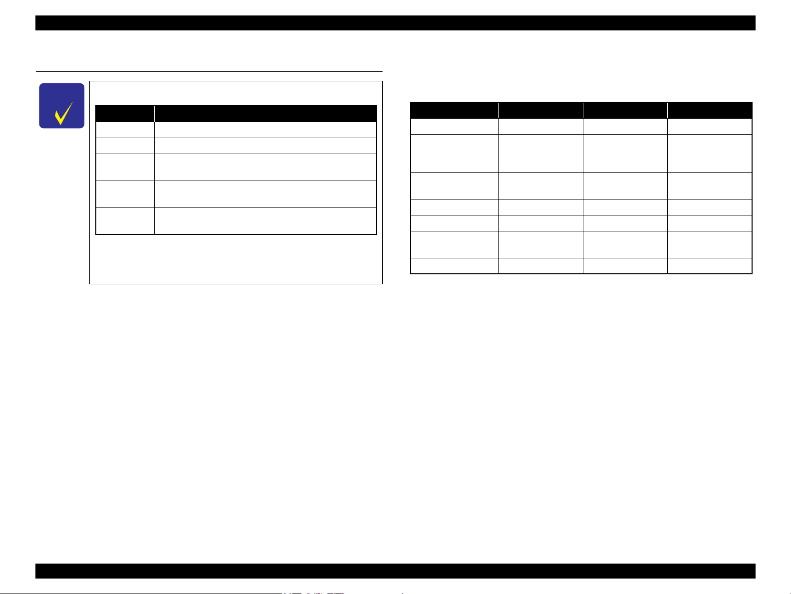
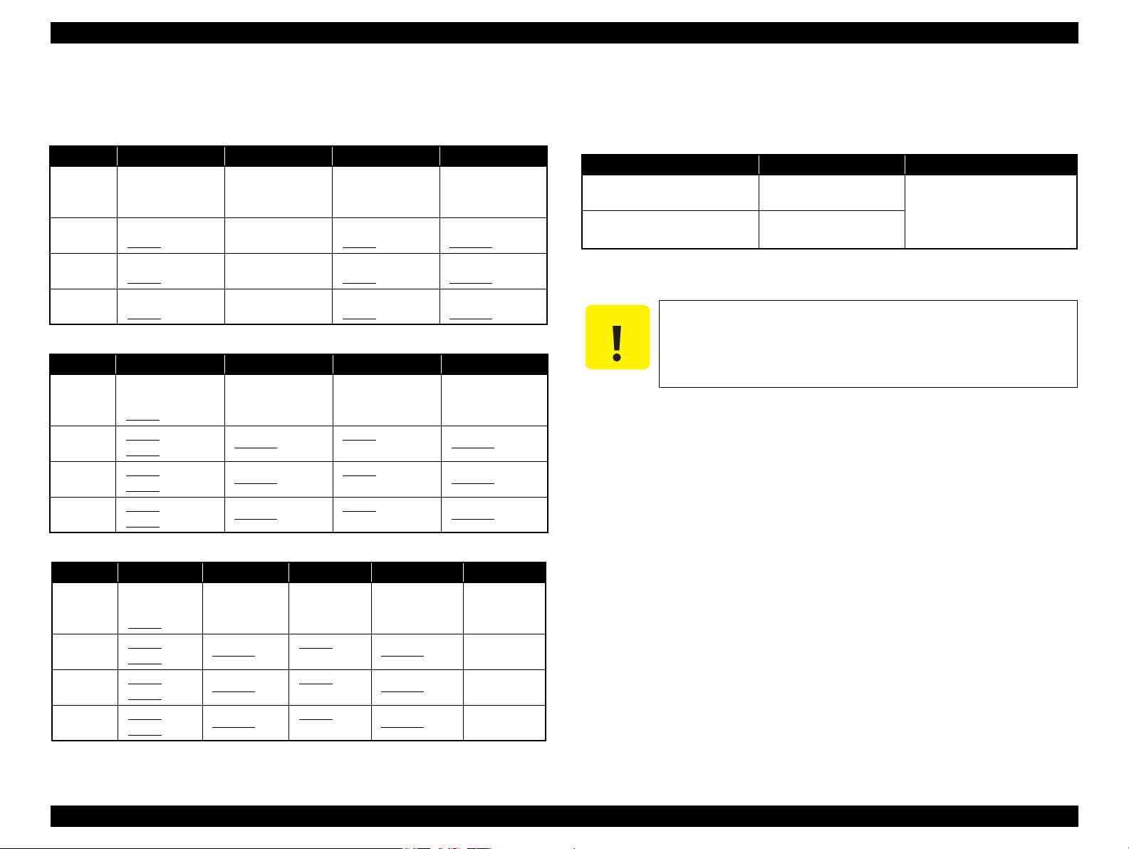
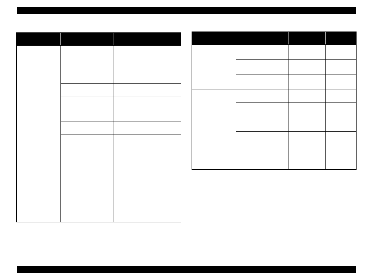
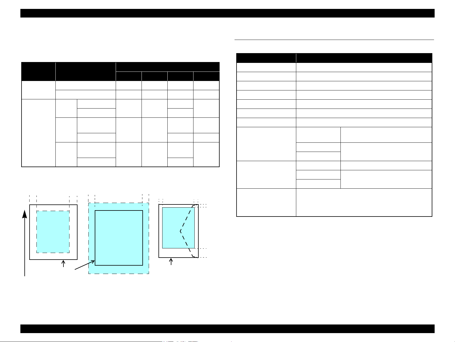
Differences of NX510/SX410/SX210 series
The differences between NX510/SX410/SX210 series are described below.
Table 1-1. Differences of NX510/SX410/SX210 series
Item NX510 series SX410 series SX210 series
Printhead
Color LCD
Scanner resolution
(Main scan x Sub scan)
Network interfaces*3Available
USB Host Port
Number of Memory
Card Slots
Scan Function
Note *1 : For the nozzle configuration, see Table 1-3.
*1
O6-chips Turbo II D4-chips Turbo II D2-chips Turbo II
2.5-inch color a-TFT
stripe LCD
(with tilt function)
*2
2.5-inch color a-TFT
stripe LCD
(with tilt function)
1.5-inch color LCD
(Cannot be tilted.)
2400 dpi x 2400 dpi 1200 dpi x 2400 dpi 1200 dpi x 2400 dpi
*4
*5
*6
*7
*2 : For the details of the scanner specifications, see “ 1.3 Scanner Specifications ” (p.23).
*3 : For the details of the network interfaces, see “ 1.5.2 Network Interface (NX510 series
only) ” (p.27).
*4 : Supports both wired network and wireless network.
*5 : Supported devices for NX510 series and SX410 series differ. For the details, see
“ 1.5.1 USB Interface ” (p.26).
*6 : CF Card slot is not mounted on SX210 series. For the details of supported memory
cards, see “ 1.5.3 Memory Card Slots ” (p.29).
*7 : For the details of the functions, see “ 1.7.2 Scan Function (NX510/SX210 series
only) ” (p.39).
Yes Yes No
2 2 1
Yes No Yes
Not Available Not Available
• Scanning from a computer
Copy
PRODUCT DESCRIPTION Features 12
• Stand alone copy using the scanning and printing functions
Memory card slot
• Available as USB memory card slot for PC
Confidential
Page 12
Epson Stylus NX510/SX410/SX210/NX420/NX220 series Revision B
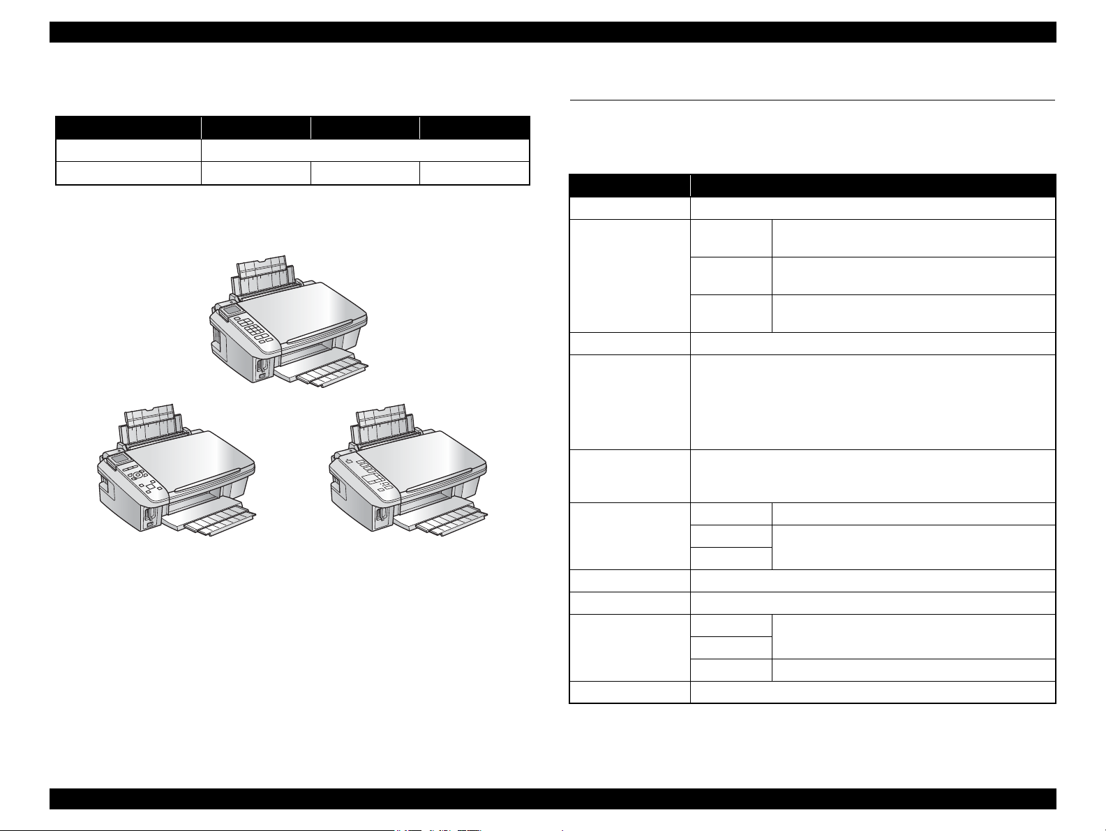
SX410 series
SX210 series
NX510 series
Dimensions
Table 1-2. Dimensions
NX510 series SX410 series SX210 series
Dimensions
Weight
Note *1 : Paper support and stacker are closed. Rubber feet are excluded
*1
*2
*2 : Excluding the weight of ink cartridges and power cable
450 mm (W) x 342 mm (D) x 182 mm (H)
6.1 kg 5.8 kg 5.7 kg
Figure 1-1. External View
1.2 Printing Specifications
1.2.1 Basic Specifications
Table 1-3. Printer Specifications
Item Specification
Print method On-demand ink jet
NX510 series
Nozzle configuration
Print direction Bi-directional minimum distance printing, Unidirectional printing
Print resolution
Control code
Input buffer size
Paper feed method Friction feed, using the ASF (Auto Sheet Feeder)
Paper path Top feed, front out
Paper feed rates
(at 25.4 mm feed)
PF interval Programmable in 0.01764 mm (1/1440 inch) steps
SX410 series
SX210 series
Horizontal x Vertical (dpi)
• 360 x 120 • 1440 x 720
• 360 x 360 • 1440 x 1440*1
• 360 x 720 • 5760 x 1440
• 720 x 720
• ESC/P Raster command
• ESC/P-R (RGB) command
• EPSON Remote command
NX510 series 132 Kbytes
SX410 series
SX210 series
NX510 series
SX410 series
SX210 series TBD
Black: 128 nozzles x 3
Color: 128 nozzles x 3 (Cyan, Magenta, Yellow)
Black: 90 nozzles x 1
Color: 90 nozzles x 3 (Cyan, Magenta, Yellow)
Black: 29 nozzles x 1
Color: 29 nozzles x 3 (Cyan, Magenta, Yellow)
64 Kbytes
95 msec. (Draft 16 ips*2), 113 msec. (Default 12 ips*2)
Note *1 : SX410 series only
*2 : ips = inch per second
PRODUCT DESCRIPTION Printing Specifications 13
Confidential
Page 13
Epson Stylus NX510/SX410/SX210/NX420/NX220 series Revision B
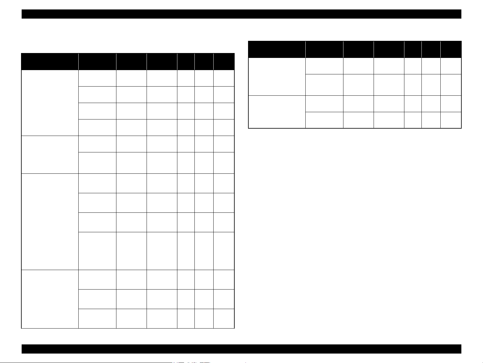
1.2.2 Ink Cartridge
Specifications for the ink cartridges for each series are explained below.
Table 1-4. Cartridge types for NX510 series
Color EAI Latin Euro CISMEA/Asia
T0971 (L2)
Black
Cyan
Magenta
Yellow
T0681 (S)
T0691 (2S)
T0682 (2S)
T0692 (3S)
T0683 (2S)
T0693 (3S)
T0684 (2S)
T0694 (3S)
T1031 (L1)
T1032 (S)
T1033 (S)
T1034 (S)
Table 1-5. Cartridge types for SX410 series
Color EAI Latin Euro CISMEA/Asia
Black
Cyan
Magenta
Yellow
T0681 (S)
T0691 (2S)
T0881 (3S)
T0692 (3S)
T0882 (4S)
T0693 (3S)
T0883 (4S)
T0694 (3S)
T0884 (4S)
T0731HN (S)
T0731N (2S)
T0732N (3S)
T0733N (3S)
T0734N (3S)
T1001 (L1)
T0711H (S)
T0711 (2S)
T1002 (S)
T0712 (3S)
T1003 (S)
T0713 (3S)
T1004 (S)
T0714 (3S)
T0711H (S)
T0711 (2S)
T0891 (3S)
T0712 (3S)
T0892 (4S)
T0713 (3S)
T0893 (4S)
T0714 (3S)
T0894 (4S)
T1031 (L1)
T0731HN (S)
T0731N (2S)
T1032 (S)
T0732N (3S)
T1033 (S)
T0733N (3S)
T1034 (S)
T0734N (3S)
T0731HN (S)
T0731N (2S)
T0732N (3S)
T0733N (3S)
T0734N (3S)
Shelf life
Two years from production date (if unopened), six months after opening package.
Storage Temperature
Table 1-7. Storage Temperature
Situation Storage Temperature Limit
When stored in individual boxes
When installed in main unit
-20 oC to 40 oC
(-4oF to 104oF)
-20 oC to 40 oC
(-4oF to 104oF)
1 month max. at 40 oC (104oF)
Dimension
12.7 mm (W) x 68 mm (D) x 47 mm (H)
C A U T I O N
Do not use expired ink cartridges.
The ink in the ink cartridge freezes at -16 °C (3.2 oF). It takes
about three hours under 25 °C (77oF) until the ink thaws and
becomes usable.
Table 1-6. Cartridge types for SX210 series
Color EAI Latin Euro CISMEA/Asia ECC/EHK
Black
Cyan
Magenta
Yellow
T0681 (S)
T0691 (2S)
T0881 (3S
T0692 (3S)
T0882 (4S)
T0693 (3S)
T0883 (4S)
T0694 (3S)
T0884 (4S)
)
T0731HN (S)
T0731N (2S)
T0732N (3S)
T0733N (3S)
T0734N (3S)
T0711H (S)
T0711 (2S)
T0891 (3S)
T0712 (3S)
T0892 (4S)
T0713 (3S)
T0893 (4S)
T0714 (3S)
T0894 (4S)
T0731HN (S)
T0731N (2S)
T0732N (3S) T1092 (2S)
T0733N (3S) T1093 (2S)
T0734N (3S) T1094 (2S)
T1091 (2S)
PRODUCT DESCRIPTION Printing Specifications 14
Confidential
Page 14
Epson Stylus NX510/SX410/SX210/NX420/NX220 series Revision B
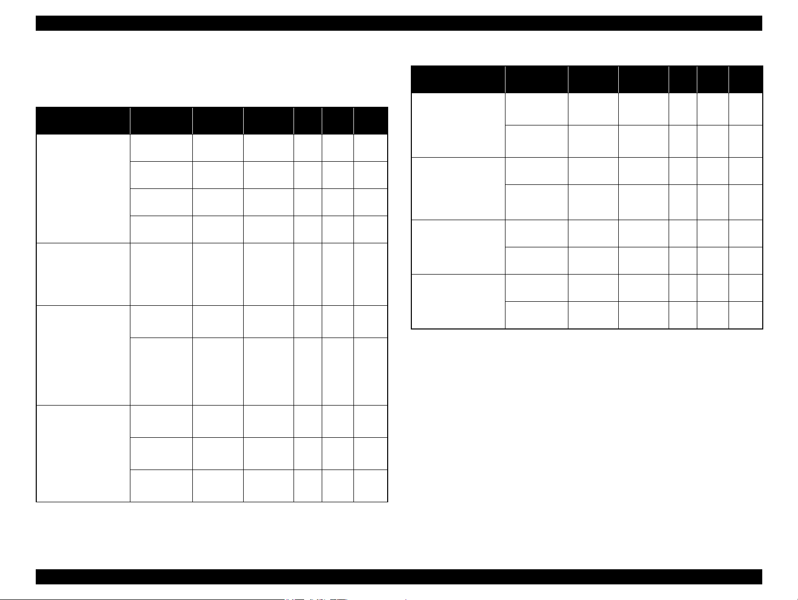
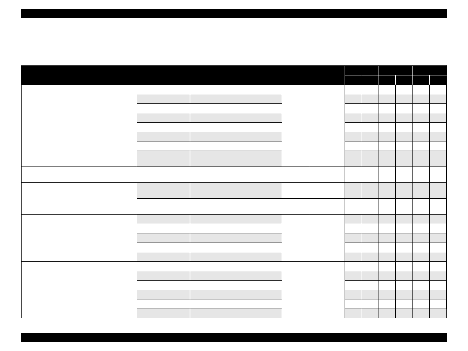
1.2.3 Print Mode
NX510 series
Table 1-8. Print Mode for NX510 series (Color)
Media Print Mode
• Plain paper
• Premium Bright
White Paper (EAI)
• Premium Bright
White Inkjet Paper
(others)
• Ultra Premium
Glossy Photo Paper
(EAI)
• Ultra Glossy Photo
Paper (others)
• Photo Paper Glossy
(EAI)
• Glossy Photo Paper
(others)
• Premium Photo
Paper Glossy (EAI)
• Premium Glossy
Photo Paper (others)
• Premium Photo
Paper Semi-Gloss
(EAI)
• Premium Semigloss
Photo Paper (other)
Resolution
(H x V dpi)
Draft 1 /
Draft 2
Normal 2 360x360
Fine 2 360x720
Photo 1 720x720
Best Photo 1440x720
Fine 1 360x720
Best Photo 1440x720
Draft 2 360x120
Fine 1 360x720
360x120
Dot Size
(cps)
Eco
(400cps)
VSD1
(300cps)
VSD2
(300cps)
VSD3
(285cps)
VSD3
(285cps)
VSD1
(300cps)
VSD3
(285cps)
Eco
(400cps)
VSD1
(300cps)
Micro
Bi-d
Weave
ON OFF N/A
ON OFF N/A
ON ON N/A
ON ON N/A
ON ON OK
ON ON OK
ON ON OK
ON OFF N/A
ON ON OK
Border-
less
Table 1-8. Print Mode for NX510 series (Color)
Media Print Mode
Photo Paper* (other)
• Premium
Presentation Paper
Matte (EAI)
• Matte Paper Heavyweight (others)
• Photo Quality Inkjet
Paper* (others)
Envelope
Note* : Not supported in EAI.
Resolution
(H x V dpi)
Fine 1 360x720
Best Photo 1440x720
Photo 2 720x720
Best Photo 1440x720
Photo 2 720x720
Best Photo 1440x720
Normal 2 360x360
Fine 2 360x720
Dot Size
(cps)
VSD1
(300cps)
VSD3
(285cps)
VSD2
(285cps)
VSD3
(285cps)
VSD2
(285cps)
VSD3
(285cps)
VSD1
(300cps)
VSD2
(300cps)
Micro
Bi-d
Weave
ON ON OK
ON ON OK
ON ON
ON ON
ON ON
ON ON
OFF OFF
OFF ON
Border-
less
OK
OK
N/A
N/A
N/A
N/A
Best Photo 1440x720
VSD3
(285cps)
ON ON OK
PRODUCT DESCRIPTION Printing Specifications 15
Confidential
Page 15
Epson Stylus NX510/SX410/SX210/NX420/NX220 series Revision B
Table 1-9. Print Mode for NX510 series (Monochrome)
Media Print Mode
• Plain paper
• Premium Bright
White Paper (EAI)
• Premium Ink Jet
Plain papers (others)
• Ultra Premium
Glossy Photo Paper
(EAI)
• Ultra Glossy Photo
Paper (others)
• Photo Paper Glossy
(EAI)
• Glossy Photo Paper
(others)
• Premium Photo
Paper Glossy (EAI)
• Premium Glossy
Photo Paper (others)
• Premium Photo
Paper Semi-Gloss
(EAI)
• Premium Semigloss
Photo Paper (other)
Resolution
(H x V dpi)
Draft 3 /
Draft 4
Normal 1 360x360
Fine 2 360x720
Photo 1 720x720
Best Photo 1440x720
Fine 1 360x720
Best Photo 1440x720
Draft 4 360x360
Fine 1 360x720
360x360
Dot Size
(cps)
Eco
(400cps)
VSD1
(300cps)
VSD2
(300cps)
VSD3
(285cps)
VSD3
(285cps)
VSD1
(300cps)
VSD3
(285cps)
Eco
(400cps)
VSD1
(300cps)
Micro
Bi-d
Weave
ON OFF N/A
ON OFF N/A
ON ON N/A
ON ON N/A
ON ON OK
ON ON OK
ON ON OK
ON OFF N/A
ON ON OK
Border-
less
Table 1-9. Print Mode for NX510 series (Monochrome)
Media Print Mode
• Premium
Presentation Paper
Matte (EAI)
• Matte Paper Heavyweight (others)
• Photo Quality Inkjet
Paper* (others)
Envelope
Note* : Not supported in EAI.
Resolution
(H x V dpi)
Photo 2 720x720
Best Photo 1440x720
Photo 2 720x720
Best Photo 1440x720
Normal 1 360x360
Fine 2 360x720
Dot Size
(cps)
VSD2
(285cps)
VSD3
(285cps)
VSD2
(285cps)
VSD3
(285cps)
VSD1
(300cps)
VSD2
(300cps)
Micro
Bi-d
Weave
ON ON OK
ON ON OK
ON ON N/A
ON ON N/A
OFF OFF N/A
OFF ON N/A
Border-
less
Best Photo 1440x720
Fine 1 360x720
Photo Paper* (other)
Best Photo 1440x720
VSD3
(285cps)
VSD1
(300cps)
VSD3
(285cps)
ON ON OK
ON ON OK
ON ON OK
PRODUCT DESCRIPTION Printing Specifications 16
Confidential
Page 16
Epson Stylus NX510/SX410/SX210/NX420/NX220 series Revision B
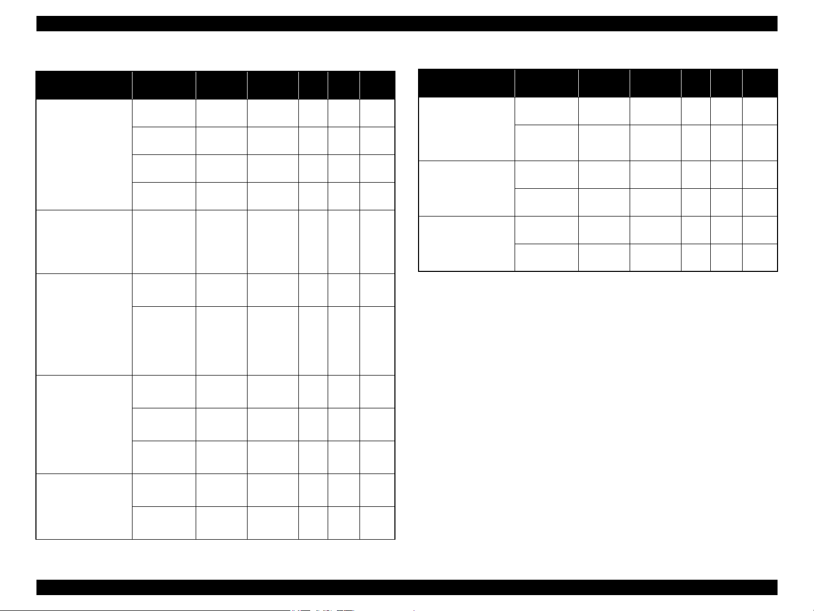
SX410 series
Media Print Mode
• Plain paper
• Premium Bright
White Paper (EAI)
• Premium Bright
White Inkjet Paper
(others)
• Ultra Premium
Glossy Photo Paper
(EAI)
• Ultra Glossy Photo
Paper (others)
• Photo Paper Glossy
(EAI)
• Glossy Photo Paper
(others)
• Premium Photo
Paper Glossy (EAI)
• Premium Glossy
Photo Paper (others)
• Premium Photo
Paper Semi-Gloss
(EAI)
• Premium Semigloss
Photo Paper (other)
Table 1-10. Print Mode for SX410 series (Color)
Resolution
(H x V dpi)
Fast Economy
/ Economy
Draft 360x120
Normal 360x360
Fine (360) 360x720
Fine (720) 720x720
Photo (1440) 1440x720
Photo 2 (1440) 1440x1440
Photo (5760) 5760x1440
Photo Draft 360x720
Photo (720) 720x720
Photo (1440) 1440x720
Photo 2 (1440) 1440x1440
Photo (5760) 5760x1440
360x120
Dot Size
(cps)
Eco
(400cps)
Eco
(400cps)
VSD1
(245cps)
VSD2
(285cps)
VSD3
(285cps)
VSD3
(285cps)
VSD3
(285cps)
VSD3
(285cps)
VSD1
(245cps)
VSD2
(285cps)
VSD3
(285cps)
VSD3
(285cps)
VSD3
(285cps)
Bi-d
ON OFF N/A
ON OFF N/A
ON OFF N/A
ON ON N/A
ON ON N/A
ON ON OK
ON ON OK
ON ON OK
ON ON OK
ON ON OK
ON ON OK
ON ON OK
ON ON OK
Micro
Weave
Border-
less
Table 1-10. Print Mode for SX410 series (Color)
Media Print Mode
Photo Draft 360x720
Photo Paper* (other)
• Premium
Presentation Paper
Matte (EAI)
• Matte Paper Heavyweight (others)
• Photo Quality Inkjet
Paper (others)
Envelope
Note* : Supports printing using the printer driver only.
Photo (720) 720x720
Photo (1440) 1440x720
Photo (720) 720x720
Photo (1440) 1440x720
Photo (720) 720x720
Photo (1440) 1440x720
Normal 360x360
Fine (720) 720x720
Resolution
(H x V dpi)
Dot Size
(cps)
VSD1
(245cps)
VSD2
(285cps)
VSD3
(285cps)
VSD2
(285cps)
VSD3
(285cps)
VSD2
(285cps)
VSD3
(285cps)
VSD1
(245cps)
VSD3
(285cps)
Micro
Bi-d
Weave
ON ON OK
ON ON OK
ON ON OK
ON ON OK
ON ON OK
ON ON
ON ON
OFF OFF N/A
OFF ON
Border-
less
N/A
N/A
N/A
PRODUCT DESCRIPTION Printing Specifications 17
Confidential
Page 17
Epson Stylus NX510/SX410/SX210/NX420/NX220 series Revision B
Table 1-11. Print Mode for SX410 series (Monochrome)
Media Print Mode
• Plain paper
• Premium Bright
White Paper (EAI)
• Premium Bright
White Inkjet Paper
(others)
• Ultra Premium
Glossy Photo Paper
(EAI)
• Ultra Glossy Photo
Paper (others)
• Photo Paper Glossy
(EAI)
• Glossy Photo Paper
(others)
• Premium Photo
Paper Glossy (EAI)
• Premium Glossy
Photo Paper (others)
• Premium Photo
Paper Semi-Gloss
(EAI)
• Premium Semigloss
Photo Paper (other)
Resolution
(H x V dpi)
Fast Economy
/ Economy
Draft 360x120
Normal 360x360
Fine (360) 360x720
Fine (720) 720x720
Photo (1440) 1440x720
Photo 2 (1440) 1440x1440
Photo (5760) 5760x1440
Photo Draft 360x720
Photo (720) 720x720
Photo (1440) 1440x720
Photo 2 (1440) 1440x1440
Photo (5760) 5760x1440
360x120
Dot Size
(cps)
Eco
(400cps)
Eco
(400cps)
VSD1
(245cps)
VSD2
(285cps)
VSD3
(285cps)
VSD3
(285cps)
VSD3
(285cps)
VSD3
(285cps)
VSD1
(245cps)
VSD2
(285cps)
VSD3
(285cps)
VSD3
(285cps)
VSD3
(285cps)
Micro
Bi-d
Weave
ON OFF N/A
ON OFF N/A
ON OFF N/A
ON ON N/A
ON ON N/A
ON ON OK
ON ON OK
ON ON OK
ON ON OK
ON ON OK
ON ON OK
ON ON OK
ON ON OK
Border-
less
Table 1-11. Print Mode for SX410 series (Monochrome)
Media Print Mode
Photo Draft 360x720
Photo Paper* (other)
• Premium
Presentation Paper
Matte (EAI)
• Matte Paper Heavyweight (others)
• Photo Quality Inkjet
Paper (others)
Envelope
Note* : Supports printing using the printer driver only.
Photo (720) 720x720
Photo (1440) 1440x720
Photo (720) 720x720
Photo (1440) 1440x720
Photo (720) 720x720
Photo (1440) 1440x720
Normal 360x360
Fine (720) 720x720
Resolution
(H x V dpi)
Dot Size
(cps)
VSD1
(245cps)
VSD2
(285cps)
VSD3
(285cps)
VSD2
(285cps)
VSD3
(285cps)
VSD2
(285cps)
VSD3
(285cps)
VSD1
(245cps)
VSD3
(285cps)
Micro
Bi-d
Weave
ON ON OK
ON ON OK
ON ON OK
ON ON OK
ON ON OK
ON ON
ON ON
OFF OFF N/A
OFF ON
Border-
less
N/A
N/A
N/A
PRODUCT DESCRIPTION Printing Specifications 18
Confidential
Page 18
Epson Stylus NX510/SX410/SX210/NX420/NX220 series Revision B
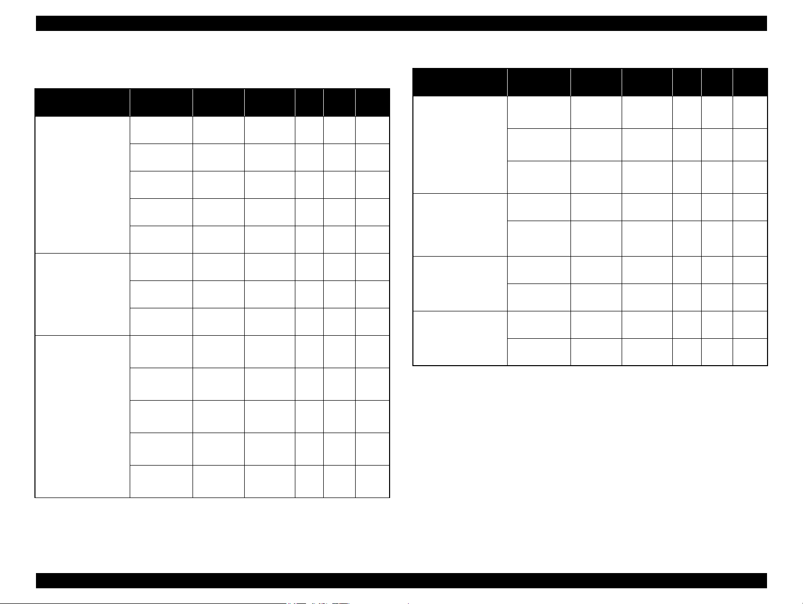
SX210 series
Media Print Mode
• Plain paper
• Premium Bright
White Paper (EAI)
• Premium Bright
White Inkjet Paper
(others)
• Ultra Premium
Glossy Photo Paper
(EAI)
• Ultra Glossy Photo
Paper (others)
• Photo Paper Glossy
(EAI)
• Glossy Photo Paper
(others)
• Premium Photo
Paper Glossy (EAI)
• Premium Glossy
Photo Paper (others)
• Premium Photo
Paper Semi-Gloss
(EAI)
• Premium Semigloss
Photo Paper (other)
Table 1-12. Print Mode for SX210 series (Color)
Resolution
(H x V dpi)
Fast Economy
/ Economy
Normal 360x360
Fine 360x720
Photo 720x720
Best Photo 1440x720
Photo RPM 5760x1440
Super Fine 360x720
Photo 720x720
Best Photo 1440x720
Photo RPM 5760x1440
360x120
Dot Size
(cps)
Eco
(400cps)
VSD1
(245cps)
VSD2
(285cps)
VSD3
(285cps)
VSD3
(285cps)
VSD3
(285cps)
VSD2
(285cps)
VSD2
(285cps)
VSD3
(285cps)
VSD3
(285cps)
Bi-d
ON OFF N/A
ON OFF N/A
ON ON N/A
ON ON OK
ON ON OK
ON ON N/A
ON ON N/A
ON ON OK
ON ON OK
ON ON N/A
Micro
Weave
Border-
less
Table 1-12. Print Mode for SX210 series (Color)
Media Print Mode
• Premium
Presentation Paper
Matte (EAI)
• Matte Paper Heavyweight (others)
Envelope
Note* : Not supported in EAI.
Resolution
(H x V dpi)
Photo 720x720
Best Photo 1440x720
Normal 360x360
Fine 360x720
Dot Size
(cps)
VSD2
(285cps)
VSD3
(285cps)
VSD1
(245cps)
VSD2
(285cps)
Micro
Bi-d
Weave
ON ON
ON ON
OFF OFF
OFF ON
Border-
less
OK
OK
N/A
N/A
VSD2
(285cps)
VSD2
(285cps)
VSD3
(285cps)
ON ON N/A
ON ON OK
ON ON OK
Photo Paper* (other)
Super Fine 360x720
Photo 720x720
Best Photo 1440x720
PRODUCT DESCRIPTION Printing Specifications 19
Confidential
Page 19

Epson Stylus NX510/SX410/SX210/NX420/NX220 series Revision B
Table 1-13. Print Mode for SX210 series (Monochrome)
Media Print Mode
• Plain paper
• Premium Bright
White Paper (EAI)
• Premium Bright
White Inkjet Paper
(others)
• Ultra Premium
Glossy Photo Paper
(EAI)
• Ultra Glossy Photo
Paper (others)
• Photo Paper Glossy
(EAI)
• Glossy Photo Paper
(others)
• Premium Photo
Paper Glossy (EAI)
• Premium Glossy
Photo Paper (others)
• Premium Photo
Paper Semi-Gloss
(EAI)
• Premium Semigloss
Photo Paper (other)
Resolution
(H x V dpi)
Fast Economy
/ Economy
Normal 360x360
Fine 360x720
Photo 720x720
Best Photo 1440x720
Photo RPM 5760x1440
Super Fine 360x720
Photo 720x720
Best Photo 1440x720
Photo RPM 5760x1440
360x120
Dot Size
(cps)
Eco
(400cps)
VSD1
(245cps)
VSD2
(285cps)
VSD3
(285cps)
VSD3
(285cps)
VSD3
(285cps)
VSD2
(285cps)
VSD2
(285cps)
VSD3
(285cps)
VSD3
(285cps)
Micro
Bi-d
Weave
ON OFF N/A
ON OFF N/A
ON ON N/A
ON ON OK
ON ON OK
ON ON N/A
ON ON N/A
ON ON OK
ON ON OK
ON ON N/A
Border-
less
Table 1-13. Print Mode for SX210 series (Monochrome)
Media Print Mode
• Premium
Presentation Paper
Matte (EAI)
• Matte Paper Heavyweight (others)
Envelope
Note* : Not supported in EAI.
Resolution
(H x V dpi)
Photo 720x720
Best Photo 1440x720
Normal 360x360
Fine 360x720
Dot Size
(cps)
VSD2
(285cps)
VSD3
(285cps)
VSD1
(245cps)
VSD2
(285cps)
Micro
Bi-d
Weave
ON ON
ON ON
OFF OFF
OFF ON
Border-
less
OK
OK
N/A
N/A
VSD2
(285cps)
VSD2
(285cps)
VSD3
(285cps)
ON ON N/A
ON ON OK
ON ON OK
Photo Paper* (other)
Super Fine 360x720
Photo 720x720
Best Photo 1440x720
PRODUCT DESCRIPTION Printing Specifications 20
Confidential
Page 20
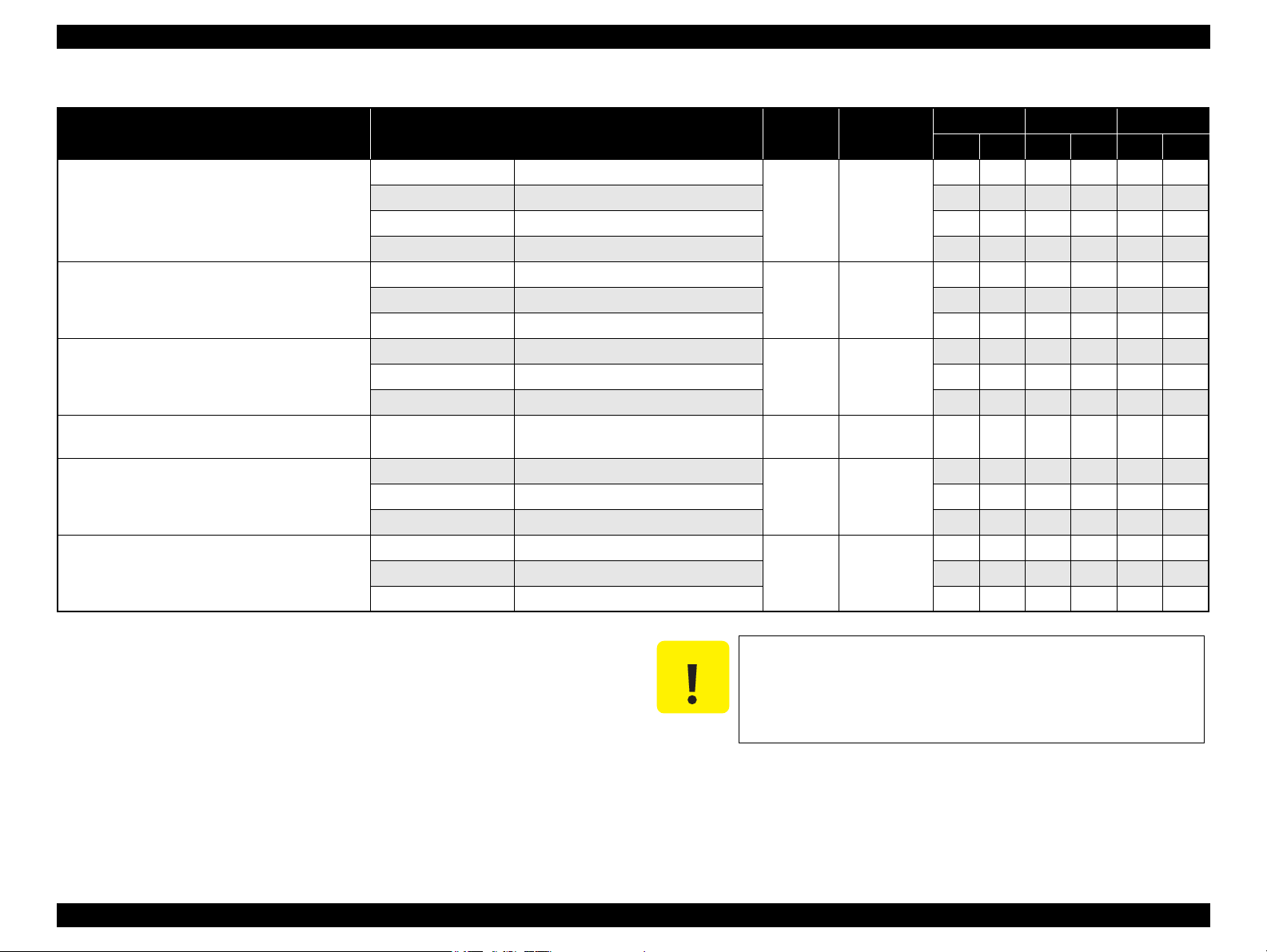
Epson Stylus NX510/SX410/SX210/NX420/NX220 series Revision B
1.2.4 Supported Paper
The table below lists the paper type and sizes supported by the printer. The supported paper type and sizes vary depending on destinations (between EAI, EUR, and Asia).
Table 1-14. Supported Paper
Paper Name Paper Size
Thickness
(mm)
Legal 215.9 x 355.6 mm (8.5”x14”)
Letter 215.9 x 279.4 mm (8.5”x11”) Y - Y - Y -
A4 210 x 297 mm (8.3”x11.7”) Y - Y - Y -
B5 182 x 257 mm (7.2”x10.1”) - - Y - Y -
Plain paper
A5 148 x 210 mm (5.8”x8.3”) - - Y - Y -
0.08-0.11
Half Letter 139.7 x 215.9 mm (5.5"x8.5”) Y - - - - -
A6 105 x 148 mm (4.2”x5.8”) Y - Y - Y -
User Defined
89 x 127- 329 x 1117.6 mm
(3.56”x 5.08” - 13.16”x44.7”)
Premium Inkjet Plain Paper A4 210 x 297 mm (8.3”x11.7”) 0.11
Premium Bright White Paper (EAI)
Bright White Inkjet Paper (Euro, Asia)
Letter 215.9 x 279.4 mm (8.5”x11”) 0.11
A4 210 x 297 mm (8.3”x11.7”) 0.13
Letter 215.9 x 279.4 mm (8.5”x11”)
A4 210 x 297 mm (8.3”x11.7”) - - Y Y Y Y
Ultra Premium Glossy Photo Paper (EAI)
Ultra Glossy Photo Paper (Euro, Asia)
8” x 10” 203.2 x 254 mm Y Y - - - -
0.30
5” x 7” 127 x 178 mm Y Y Y Y - -
4” x 6” 101.6 x 152.4 mm Y Y Y Y Y Y
Letter 215.9 x 279.4 mm (8.5”x11”)
A4 210 x 297 mm (8.3”x11.7”) - - Y Y Y Y
Premium Photo Paper Glossy (EAI)
Premium Glossy Photo Paper (Euro, Asia)
8” x 10” 203.2 x 254 mm Y Y - - - -
0.27
5” x 7” 127 x 178 mm Y Y Y Y Y Y
4" x 6
"
101.6 x 152.4 mm Y Y Y Y Y Y
16:9 wide 101.6 x 180.6 mm Y Y Y Y - -
Weight
64-90 g/m
(17-24 lb.)
80 g/m
(21 lb.)
90 g/m
(24 lb.)
92.5 g/m
(25 lb.)
290 g/m
(77 lb.)
255 g/m
(68 lb.)
2
2
2
2
2
2
EAI EUR Asia
*1
*2
*1
*2
P
B
P
B
*1
P
Y - Y - Y -
Y - Y - Y -
- - Y - Y -
Y - - - - -
- - Y - Y -
Y Y - - - -
Y Y - - - -
*2
B
PRODUCT DESCRIPTION Printing Specifications 21
Confidential
Page 21
Epson Stylus NX510/SX410/SX210/NX420/NX220 series Revision B
Note *1 : “Y” in the “P” column stands for “the paper type/size is Supported”.
*2 : “Y” in the “B” column stands for “Borderless printing is available”.
Make sure the paper is not wrinkled, fluffed, torn, or folded.
Make sure to correct the warpage of the paper before use.
When printing on an envelope, be sure the flap is folded neatly.
Do not use the adhesive envelopes.
Do not use double envelopes and cellophane window envelopes.
Table 1-14. Supported Paper
Paper Name Paper Size
Thickness
(mm)
Letter 215.9 x 279.4 mm (8.5”x11”)
Photo Paper Glossy (EAI)
Glossy Photo Paper (Euro, Asia)
A4 210 x 297 mm (8.3”x11.7”) Y Y Y Y Y Y
0.25
5” x 7” 127 x 178 mm - - Y Y - -
4” x 6” 101.6 x 152.4 mm Y Y Y Y Y Y
Letter 215.9 x 279.4 mm (8.5”x11”)
Premium Photo Paper Semi-Gloss (EAI)
Premium Semigloss Photo Paper (Euro, Asia)
A4 210 x 297 mm (8.3”x11.7”) - - Y Y Y Y
0.27
4” x 6” 101.6 x 152.4 mm Y Y Y Y Y Y
Letter 215.9 x 279.4 mm (8.5”x11”)
Premium Presentation Paper Matte (EAI)
Matte Paper-Heavyweight (Euro, Asia)
A4 210 x 297 mm (8.3”x11.7”) - - Y Y Y Y
0.23
8” x 10” 203.2 x 254 mm Y Y - - - -
Photo Quality Inkjet Paper A4 210 x 297 mm (8.3”x11.7”) 0.13
#10 104.8 x 241.3 mm (4.125”x9.5”)
Envelopes
#DL 110 x 220 mm - - Y - Y -
-
#C6 114 x 162 mm - - Y - Y -
A4 210 x 297 mm (8.3”x11.7”)
Photo Paper
5” x 7” 127 x 178 mm - - Y Y - -
0.24
4” x 6” 101.6 x 152.4 mm - - Y Y Y Y
Weight
258 g/m
(68 lb.)
250 g/m
(66 lb.)
167 g/m
(44 lb.)
102 g/m
(27 lb.)
75-100 g/m
(20-27 lb.)
190 g/m
(51 lb.)
2
2
2
2
2
2
EAI EUR Asia
*1
*2
*1
*2
P
B
P
B
*1
P
Y Y - - - -
Y Y - - - -
Y Y - - - -
- - Y - Y -
Y - Y - Y -
- - Y Y Y Y
B
*2
PRODUCT DESCRIPTION Printing Specifications 22
C A U T I O N
Confidential
Page 22
Epson Stylus NX510/SX410/SX210/NX420/NX220 series Revision B
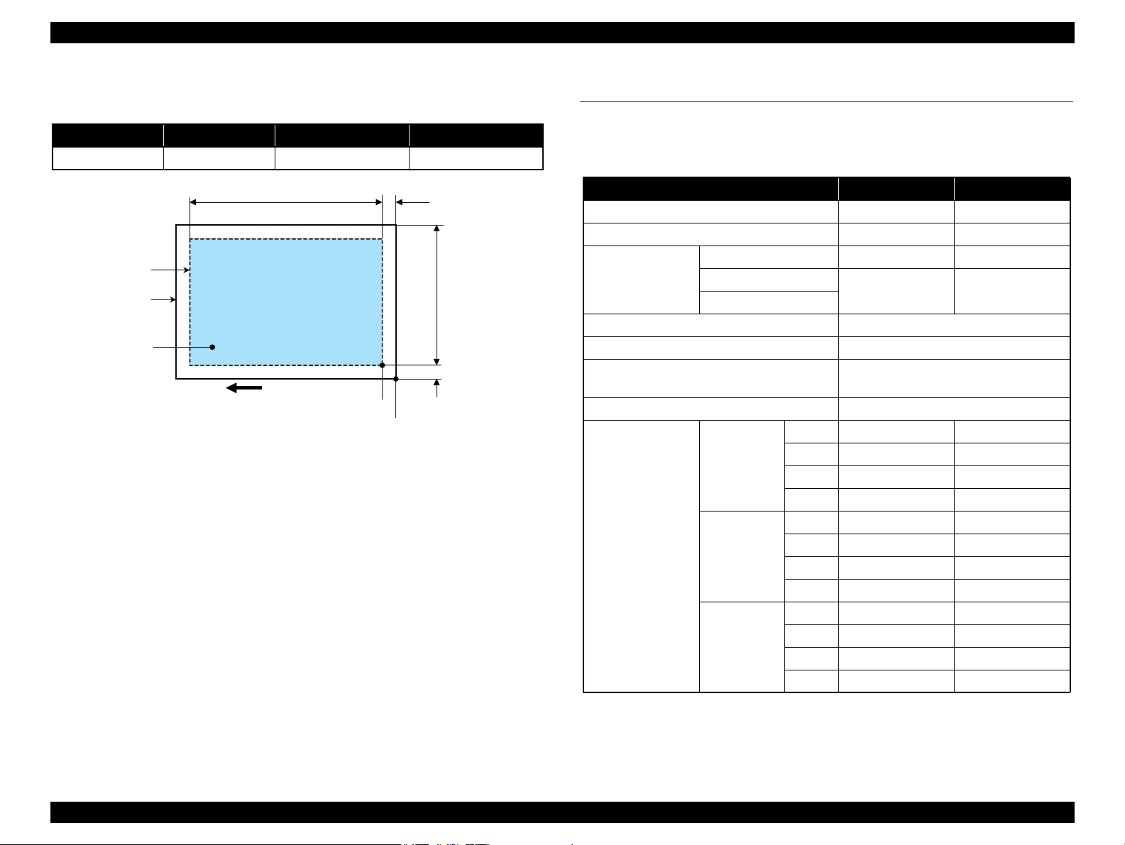
Print Area
LM RM
TM
BM
BM
Cut Sheet (Standard)
Cut Sheet (Borderless)
Paper SIze
LM
RM
TM
BM
Print Area
LM RM
Print Area
Envelope
Paper Size
TM
Paper Feed Direction
1.2.5 Printing Area
The printing area for this printer is shown below.
Table 1-15. Printing Area (Margins)
Print Mode Paper Size
Standard print
Borderless
*
print
Note * : The margins for Borderless print are margins that bleed off the edges of paper.
Any size 3 mm 3 mm 3 mm 3 mm
Envelope 5 mm 5 mm 3 mm 20 mm
NX510
series
SX410
series
SX210
series
4” x 6”
Others 2.96 mm
A4/Letter to 2L/
5” x 7”/16” x 9”
4” x 6” 2.54 mm 3.53 mm
A4/Letter to 2L/
5” x 7”/16” x 9”
4” x 6” 2.82 mm
Left Right Top Bottom
2.54 mm 2.54 mm
2.54 mm 2.54 mm
2.54 mm 2.54 mm
Margin
2.8 mm
2.96 mm 4.02 mm
2.96 mm
3.39 mm
3.39 mm
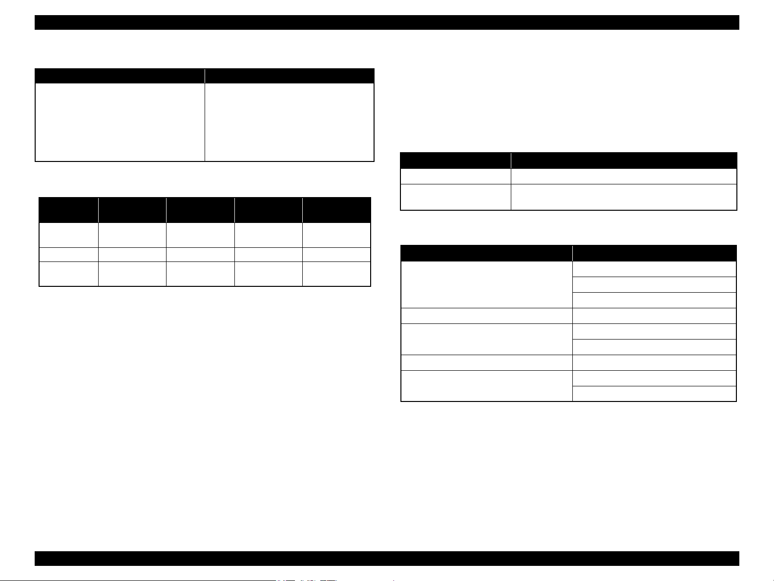
1.3 Scanner Specifications
Table 1-16. Basic Specifications
Item Specification
Scanner type Flatbed, color
Scanning method Moving carriage, stationary document
Home position The front right corner
Photoelectric device CIS
Light source LED
Maximum document sizes A4 or US letter
Scanning range 8.5" x 11.7" (216 mm x 297 mm)
Main scan: 2400 dpi
Sub scan: 2400 dpi
Main scan: 1200 dpi
Sub scan: 2400 dpi
10,200 x 14,040 pixels
24 bit per pixel (output).
1 bit* / 8 bit per pixel (output)
Maximum resolution
Maximum effective pixels
Pixel depth
NX510 series
SX210 series
SX410 series
NX510 series 20,400 x 28,800 pixels
SX410 series
SX210 series
Color: 48 bit per pixel (input) and
Monochrome: 16 bit per pixel (input) and
PRODUCT DESCRIPTION Scanner Specifications 23
Figure 1-2. Printing Area
Note * : NX510 series only.
Confidential
Page 23
Epson Stylus NX510/SX410/SX210/NX420/NX220 series Revision B
a
RW
RL
OTM
OLM
Scanning starting position
Scan area
Scan bed
Original
(facedown)
Home position
1.3.1 Scanning Range
Table 1-17. Scanning Range
RL (read length) RW (read width) OLM (left margin) OTM (top margin)
216 mm 297 mm 1.5 mm 1.5 mm
Figure 1-3. Scanning Range
1.4 General Specifications
1.4.1 Electrical Specifications
Table 1-18. Primary Power Specifications
Item 100-120 V model 220-240 V model
Rated power supply voltage 100 to 120 VAC 220 to 240 VAC
Input voltage range 90 to 132 VAC 198 to 264 VAC
NX510 series 0.6 A (1.3 A) 0.3 A (0.6 A)
Rated current
(Max. rated current)
Rated frequency 50 to 60 Hz
Input frequency range 49.5 to 60.5 Hz
Insulation resistance
(Primary - Secondary, 10 mA at 25 oC)
Energy conservation
Power consumption
Note* : Printing pattern: ISO/IEC24712
Note : When no operation is made with the control panel for more than 13 minutes, the panel
goes to the power save mode within two minutes.
SX410 series
SX210 series
NX510 series
SX410 series
SX210 series
0.6 A (1.0 A) 0.3 A (0.5 A)
3,000 V (for one minute)
International Energy Star Program compliant
Copy* Approx. 16 W Approx. 16 W
Ready Approx. 6.0 W Approx. 6.0 W
Sleep Approx. 3.5 W Approx. 4.0 W
Off Approx. 0.2 W Approx. 0.3 W
*
Copy
Ready Approx. 5.0 W Approx. 5.0 W
Sleep Approx. 2.5 W Approx. 3.0 W
Off Approx. 0.2 W Approx. 0.3 W
Copy
Ready Approx. 5.0 W Approx. 5.0 W
Sleep Approx. 2.5 W Approx. 2.5 W
Off Approx. 0.2 W Approx. 0.3W
Approx. 12 W Approx. 12 W
*
Approx. 11 W Approx. 11 W
PRODUCT DESCRIPTION General Specifications 24
Confidential
Page 24

Epson Stylus NX510/SX410/SX210/NX420/NX220 series Revision B
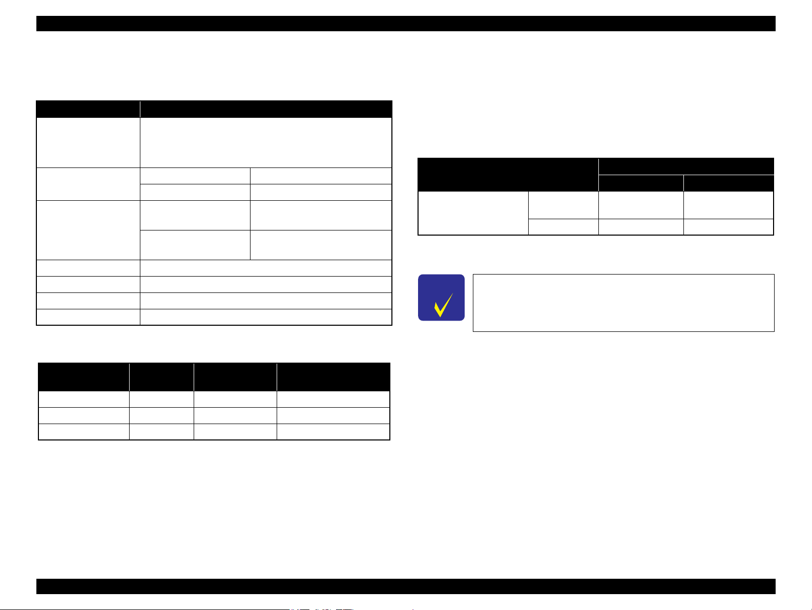
10/50
27/80
35/9520/68
Temperature (°C/°F)
20
30
40
50
90
80
70
60
Humidity (%)
30/86 40/104
1.4.2 Environmental Conditions
Table 1-19. Environmental Conditions
*3
*1
Humidity
20 to 80%
Condition Temperature
Operating
Storage
(unpacked)
10 to 35°C
(50 to 95°F)
-20 to 40°C
(-4°F to 104°F)
Note *1 : The combined Temperature and Humidity conditions must be within the blue-shaded
range in Fig.1-4.
*2 : No condensation
*3 : Must be less than 1 month at 40°C.
5 to 85%
*1,2
Shock Vibration
1G
(1 msec or less)
10 to 55Hz
2G
(2 msec or less)
10 to 55Hz
0.15G,
0.50G,
1.4.3 Durability
Table 1-20. Durability
Model Total print life
Black 20,000 pages
NX510 series
(TBD)
Color 10,000 pages
*1
*2
Four billions shots
*3
(per nozzle) (TBD)
Printhead
(TBD)
SX410 series
SX210 series
Black 10,000 pages
Color 10,000 pages
*2
Five billions shots
*3
(per nozzle)
Note *1 : The specified value or five years whichever comes first
*2 : A4, 3.5% duty, ECMA pattern, Plain paper, Default mode
*3 : A4, ISO 24712 pattern, Plain paper, Default mode
1.4.4 Acoustic Noise
NX510 series: 42.5 dB
SX410 series: 41 dB
SX210 series: 37.7 dB
Note : When printing from PC, on Premium Glossy Photo Paper, in highest quality
*1
Scanner carriage
30,000 cycles of
carriage movement
(TBD)
30,000 cycles of
carriage movement
Figure 1-4. Temperature/Humidity Range
C A U T I O N
PRODUCT DESCRIPTION General Specifications 25
When returning the repaired printer to the customer, make sure
the Printhead is covered with the cap and the ink cartridge is
installed.
If the Printhead is not covered with the cap when the printer is
off, turn on the printer with the ink cartridge installed, make
sure the Printhead is covered with the cap, and then turn the
printer off.
Confidential
Page 25

Epson Stylus NX510/SX410/SX210/NX420/NX220 series Revision B
1.4.5 Safety Approvals (Safety standards/EMI)
USA UL60950-1
FCC Part15 Subpart B Class B
Canada CSA No.60950-1
CAN/CSA-CEI/IEC CISPR 22 Class B
Mexico NOM-019-SCFI-1998
Taiwan CNS13438 Class B
CNS14336 (IEC60950)
EU EN60950-1
EN55022 Class B
EN61000-3-2, EN61000-3-3
EN55024
Russia GOST-R (IEC60950, CISPR 22)
Korea K60950-1
KN22 Class B
KN61000-4-2/-3/-4/-5/-6/-11
Argentina IEC60950-1
Australia AS/NZS CISPR22 Class B
Singapore
Hong Kong
China
Note *1 : SX410 series is not compliant.
*1
*1
*1*2
IEC60950-1
IEC60950-1
GB8898
GB13837 Class B, GB17625.1
*2 : NX510 series is not compliant.
1.5 Interface
This printer has USB interface and memory card slots of the following specifications.
1.5.1 USB Interface
The mounted USB Interfaces differ between NX510/SX410/SX210 series. These
products are equipped with the USB Device Port to connect a computer. Moreover,
NX510/SX410 series are equipped with the USB Host Port to connect an external
device such as a DSC (Digital Still Camera), etc. The specifications of each USB port
are provided below.
Table 1-21. USB Interface Specifications
Item USB Device port USB Host port
• Universal Serial Bus
Specifications Revision 2.0
• Universal Serial Bus Device
Compatible standards
Transfer rate
NX510 series
SX410 series
Class Definition for Printing
Devices Version 1.1
• Universal Serial Bus Mass
Storage Class Bulk-Only
Transport Revision 1.0
480 Mbps (High Speed)
Data format
Compatible connector
Max. cable length
Note* : The following devices can be connected to the USB Host port. (Not supported for
SX210 series)
• Devices compliant with DPS Version 1.0/1.1 (PictBridge)
• Devices compliant with Universal Serial Bus Mass Storage Class Bulk-Only Transport
Revision 1.0, and the Subclass code is one of the followings. (NX510 series only)
0x06 (SCSI transparent command set)
0x05 (SFF-8070i command set)
0x02 (SFF-8020i command set)
USB Series B USB Series A
2 [m] or less
• Universal Serial Bus
Specifications Revision
2.0
480 Mbps (MAX)
12 Mbps (MAX)
NRZI
*
PRODUCT DESCRIPTION Interface 26
Confidential
Page 26
Epson Stylus NX510/SX410/SX210/NX420/NX220 series Revision B
Table 1-22. Device ID
When IEEE 1284.4 is Enabled When IEEE 1284.4 is Disabled
@EJL<SP>ID<CR><LF>
MFG:EPSON;
CMD:ESCPL2,BDC,D4,D4PX,ESCPR1;
MDL:Model Name;
CLS:PRINTER;
DES:EPSON<SP>Model Name;
CID:EpsonRGB;
The “Model Name” is replaced as shown in the following table.
Table 1-23. Model Names Indicated in the Device ID
Destination North America Euro
NX510 series
SX410 series TBD TBD TBD ---
SX210 series
Epson Stylus
NX510
Epson Stylus
NX210
Epson Stylus
Epson Stylus
@EJL<SP>ID<CR><LF>
MFG:EPSON;
CMD:ESCPL2,BDC;ESCPR1;
MDL:Model Name;
CLS:PRINTER;
DES:EPSON<SP>Model Name;
CID:EpsonRGB;
Latin/Asia/
Pacific
Epson Stylus
SX510W
SX210
TX510W
Epson Stylus
TX210
OFFICE 510
China
---
Epson ME
1.5.2 Network Interface (NX510 series only)
NX510 series can be connected to the network via Wired or Wireless LAN connection.
(They can not be used simultaneously.) The following describes each Interface.
Wired LAN
The following interface is equipped for the Wired LAN connection. The
communication mode can be selected from auto setting or fixed setting.
Table 1-24. Wired LAN
Item Content
Connector RJ-45 receptacle*: 1 port
Communication Speed For either 10Base-T or 100Base-TX, the Full Duplex or Half
Duplex can be selected.
Note* : 10Base-T/100Base-TX Ethernet is supported. MDI/MDI-X is selected automatically.
Table 1-25. Combination of the Wired LAN communication mode settings
Setting of this printer Setting of the connected device
Auto Setting (AUTO)
Auto Setting
100BASE-TX Full Duplex 100BASE-TX Full Duplex
100BASE-TX Half Duplex
10BASE-T Full Duplex 10BASE-T Full Duplex
10BASE-T Half Duplex
100BASE-TX Half Duplex
10BASE-T Half Duplex
Auto Setting (AUTO)
100BASE-TX Half Duplex
Auto Setting (AUTO)
10BASE-T Half Duplex
PRODUCT DESCRIPTION Interface 27
Confidential
Page 27
Epson Stylus NX510/SX410/SX210/NX420/NX220 series Revision B
Wireless LAN
The following interface is equipped for the Wireless LAN connection.
:
Table 1-26. Wireless LAN
Item Content
Applied Standard
(2.4GHz spectrum band
wireless network
standards)
Wireless Operation Mode IEEE802.11b DS-SS (Half Duplex)
Communication Range
(line-of-sight distance)
Communication Mode Ad-hoc (IBSS) or Infrastructure (ESS)
Roaming Function Not supported
Output Signal Intensity 10mW
Antenna Built-in antenna (Diversity function is not supported)
Note " * " : Referential value. It depends on surrounding conditions.
Conforms to IEEE802.11b, IEEE802.11g
IEEE802.11g OFDM (Half Duplex)
IEEE802.11b (11Mbps) • 60m (indoor)
*
IEEE802.11g (54Mbps) • 20m (indoor)
• 220m (outdoor)
• 100m (outdoor)
Switching Wired/Wireless LAN
This printer can be connect to the network via either Wired LAN or Wireless LAN
connection only.
Enabling/disabling the Wireless LAN can be made from the Control Panel. When the
Wireless LAN is enabled, it gets priority over the Wired Lan regardless of whether the
LAN Cable is connected. The default Wireless LAN setting is “Disabled”.
Table 1-28. Wireless LAN Setting from the Control Panel
Setting from Control Panel
Wireless LAN Disabled
(Default)
Enabled
Note* : No service via network is available without connecting the LAN Cable (because
network communication is not established.) except printing a status sheet or the like.
C H E C K
P O I N T
When changing the networks while the power is on, wait at least for
10 seconds between disconnecting and reconnecting.
LAN Cable Connection State
Connected Disconnected
Wired LAN ---
Wireless LAN
*
Wireless LAN
Table 1-27. Available Channels and Standard
Frequency Band
(GHz)
2.400 - 2.4835 1 - 13 802.11b 11/5.5/2/1M
2.400 - 2.4835 1 - 13 802.11g 54/48/36/24/18/12/9/6M
2.471 - 2.497 14 802.11/11b 11/5.5/2/1M
Note " * " : The communication speed will be changed automatically, depending on radio wave
strength. bps = bit per second.
Channel IEEE Standard
Communication Speed
(bps)
*
PRODUCT DESCRIPTION Interface 28
Confidential
Page 28
Epson Stylus NX510/SX410/SX210/NX420/NX220 series Revision B
1.5.3 Memory Card Slots
If you insert a Memory Stick DUO to the Memory Card Slot
O NC A U T I
without using the adapter, make sure to turn off the printer first,
then remove the card using tweezers.
Table 1-29. List of Supported Memory Card
Priority
1
2
3
4
Note: • Memory Stick/PRO, SD/MMC and xD-Picture Card shares the same slot.
Slot Compatible memory card Standard Max. capacity Remarks
Memory Stick/
Memory Stick
PRO
SD/MMC SD (Security Digital) SD Memory Card Specifications / PART1. Physical Layer Specification
xD-Picture card xD-Picture card xD-Picture Card Specification Ver.1.20 compatible
CF Type II
(No slot provided
for SX210 series)
Memory Stick “Memory Stick Standard” Format Specification Ver.1.43-00 compatible 128MB Includes versions with memory select function
MagicGate Memory Stick Copy protection function is not supported
MagicGate Memory Stick Duo An adapter should be used
Memory Stick PRO Memory Stick PRO Format Specifications-without security specifications
Ver.1.02-00 compatible
Memory Stick Duo The Memory Stick Duo adapter should be used
Memory Stick Pro Duo The Memory Stick Duo adapter should be used.
Memory Stick micro The Memory Stick adapter for standard size should be used.
miniSD/microSD The SD adapter should be used
SDHC 32GB Speed Class is not supported
miniSDHC/microSDHC The SD adapter should be used
MultiMediaCard
MultiMediaCard Plus
Compact Flash CF+ and CompactFlash Specification Revision 4.1 compatible 32GB True-IDE compatible memory card only
Microdrive
Ver. 2.0 compatible
MultiMediaCard Standard Ver. 4.2 compatible
32GB
2GB
4GB/32GB
2GB
Copy protection function is not supported
Speed Class is not supported
Only MultiMediaCard Plus supports 32GB
Type M/H supported
cannot be accessed.
• When cards are inserted in the two slots at once, the slot which will be accessed first is
determined according to the priority shown in the table.
• To select a card that has been inserted in a non-active slot, first remove the card in the
active slot.
• In memory card direct printing mode, the image files in the active slot are valid and
have assigned frame numbers. The number of images will not change if a card is
(This is for Windows. For Macintosh, the card in the active slot will be mounted on the
desktop.)
• Does not support 5V type of memory cards.
• When a memory card is being accessed, do not touch the memory card.
• For detailed information on the supported file system and formatting the memory card,
refer to “ 1.7.3 Memory Card Direct Print Function ( p. 39 ) ”.
inserted in another nonselected slot.
• When the card inserted in the slot is accessed from the PC, only one drive is displayed
at a time as a removable disk* and only the card that is in the active slot can be
accessed via the removable disk. A card that has been inserted into a non-selected slot
PRODUCT DESCRIPTION Interface 29
Confidential
Page 29
Epson Stylus NX510/SX410/SX210/NX420/NX220 series Revision B
Power button
Start button
Stop/Clear button
Copy button
Memory Card button
Scan button
Display/Crop button
Setup button
- button
Menu button
Back button
+ button
LCD
Power LED
Cross key and OK button
Note : The Card Access LED is provided near the memory card slot.
WiFi LED
Photo button
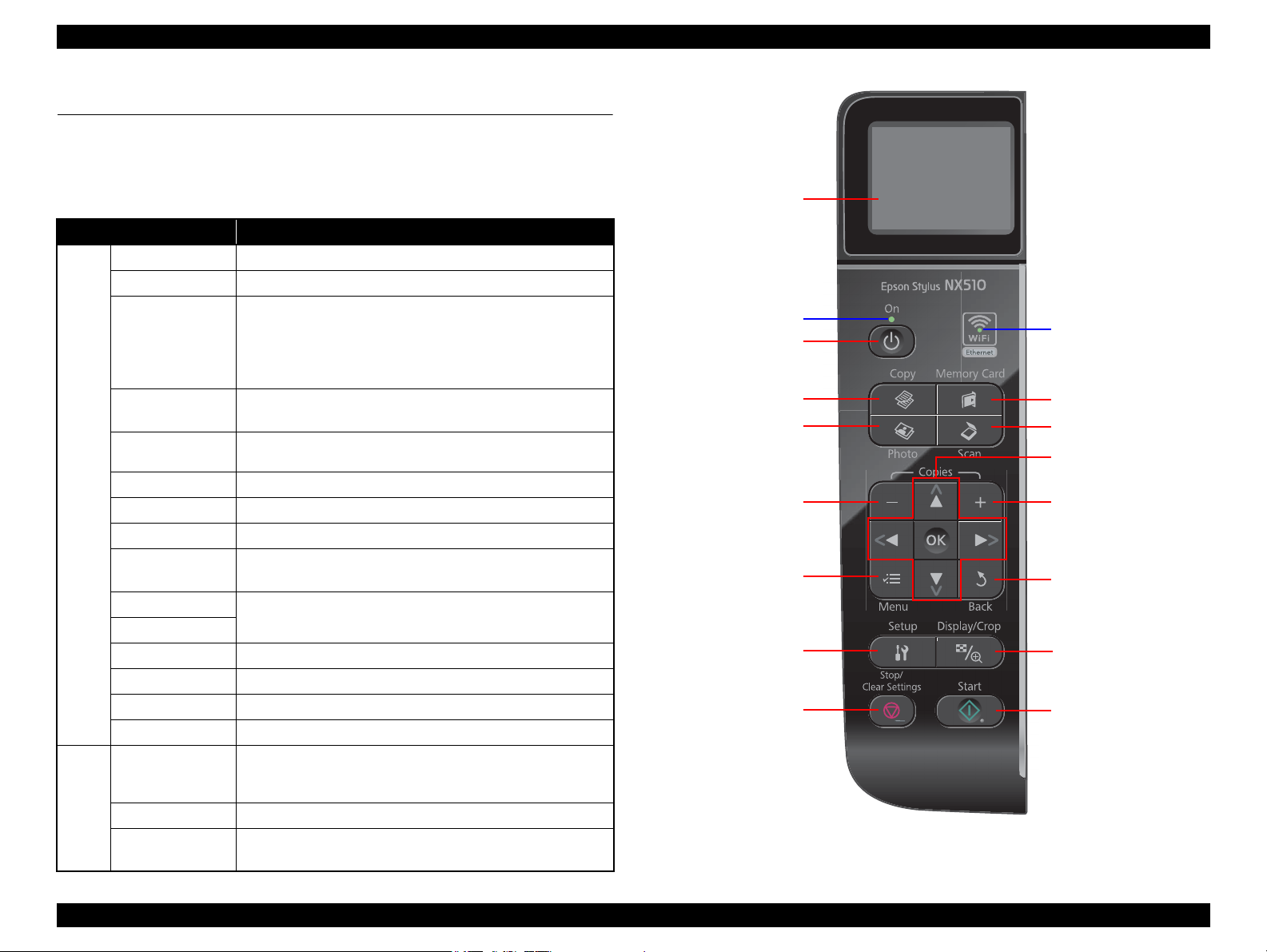
1.6 Control Panel
1.6.1 Operation Buttons & LEDs
NX510 series
Table 1-30. NX510 series Buttons & LEDs
Button/LED Function
Power Turns the power ON/OFF.
Start Starts printing.
Stop/Clear
Setup
Button
LED
Display/Crop
Menu Goes to the print setting menu screen.
OK Accepts the changed settings
Back Cancels the previous operation.
Cross Key
(Up/Down/Left/Right)
+
-
Copy Goes to the stand alone Copy mode.
Memory Card Goes to the memory card direct print mode.
Photo Goes to the Photo mode. (Repeat printing)
Scan Goes to the Scan mode.
Power (Green)
WiFi (Green) • Flashes when wireless LAN connected
Card Access
(Green)
• Stops operation and displays the menu screen.
• Stops printing and ejects paper.
• Returns the print settings in the current mode to their default
and displays the Top screen. (Returns to the previous screen
during printing maintaining the current settings)
Goes to the Setup mode that provides maintenance menu (head
cleaning, head alignment, etc.) and various setting menu.
• Goes to the zoom setting screen for the selected image.
• Changes the image preview layout on the LCD.
Selects a menu item or a setting value.
Sets the number of copies.
• Flashes at power ON/OFF.
• Flashes during some sequence is in progress.
• Flashes when an fatal error occurs.
• Lights when a memory card is inserted.
• Flashes when a memory card is being identified or accessed.
Figure 1-5. NX510 series Control Panel
PRODUCT DESCRIPTION Control Panel 30
Confidential
Page 30
Epson Stylus NX510/SX410/SX210/NX420/NX220 series Revision B
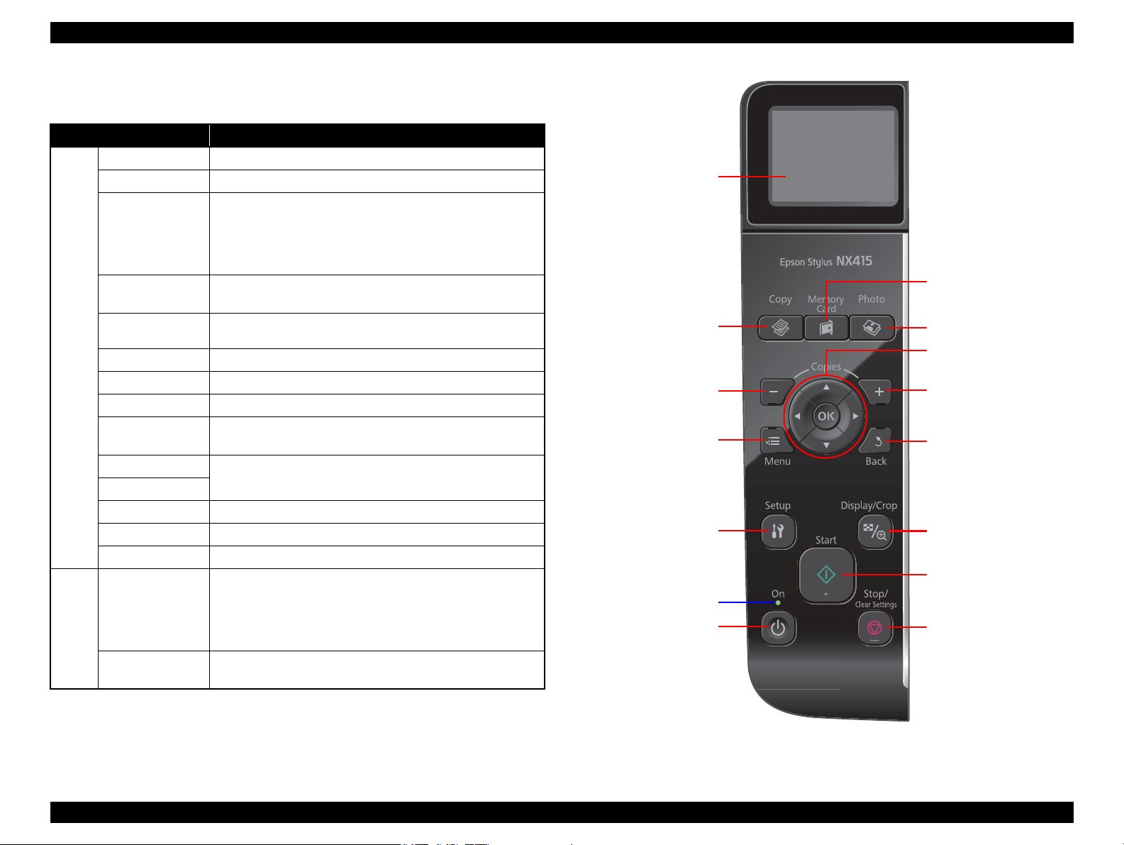
Power button
Start button
Stop/Clear button
Copy button
Memory Card button
Photo button
Display/Crop button
Setup button
- button
Menu button
Back button
+ button
LCD
Power LED
Cross key and OK button
Note : The Card Access LED is provided near the memory card slot.
SX410 series
Table 1-31. SX410 series Buttons & LEDs
Button/LED Function
Power Turns the power ON/OFF.
Start Starts printing.
• Stops operation and displays the menu screen.
• Stops printing and ejects paper.
Button
LED
Stop/Clear
Setup
Display/Crop
Menu Goes to the print setting menu screen.
OK Accepts the changed settings
Back Cancels the previous operation.
Cross Key
(Up/Down/Left/Right)
+
-
Copy Goes to the stand alone Copy mode.
Memory Card Goes to the memory card direct print mode.
Photo Goes to the Photo mode. (Repeat printing)
Power (Green)
Card Access
(Green)
• Returns the print settings in the current mode to their default
and displays the Top screen. (Returns to the previous screen
during printing maintaining the current settings)
Goes to the Setup mode that provides maintenance menu (head
cleaning, head alignment, etc.) and various setting menu.
• Goes to the zoom setting screen for the selected image.
• Changes the image preview layout on the LCD.
Selects a menu item or a setting value.
Sets the number of copies.
• Flashes at power ON/OFF.
• Flashes during some sequence is in progress.
• Flashes when an fatal error occurs.
• Lights when the status is other than above. (i.e. when in
stand-by / in setting operation using the control panel)
• Lights when a memory card is inserted.
• Flashes when a memory card is being identified or accessed.
Figure 1-6. SX410 series Control Pane
PRODUCT DESCRIPTION Control Panel 31
Confidential
Page 31
Epson Stylus NX510/SX410/SX210/NX420/NX220 series Revision B
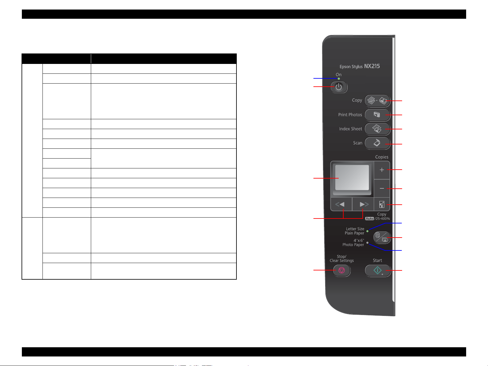
Power button
Start button
Stop/Clear button
Copy button
Photo button
Scan button
Paper Type button
- button
Left/Right button
+ button
LCD
Power LED
Note : The Card Access LED is provided near the memory card slot.
Index Sheet button
Paper LED
Paper LED
Zoom button
SX210 series
Table 1-32. SX210 series Buttons & LEDs
Button/LED Function
Power Turns the power ON/OFF.
Start Starts printing.
• Stops operation and displays the menu screen.
• Stops printing and ejects paper.
Stop/Clear
Paper Type Selects paper type and size.
Zoom Goes to the zoom setting screen.
Button
Left/Right Selects a menu item or a setting value.
+
-
Copy Goes to the stand alone Copy mode.
Photo Goes to the memory card direct print mode.
Index Sheet Prints an index sheet.
Scan Goes to the Scan mode.
Index Sheet + Scan Goes to the Setup mode.
Power (Green)
LED
Paper (Green) Selected paper type and size light.
Card Access
(Green)
• Returns the print settings in the current mode to their default
and displays the Top screen. (Returns to the previous screen
during printing maintaining the current settings)
Sets the number of copies.
• Flashes at power ON/OFF.
• Flashes during some sequence is in progress.
• Flashes when an fatal error occurs.
• Lights when the status is other than above. (i.e. when in
stand-by / in setting operation using the control panel)
• Lights when a memory card is inserted.
• Flashes when a memory card is being identified or accessed.
Figure 1-7. SX210 series Control Pane
PRODUCT DESCRIPTION Control Panel 32
Confidential
Page 32

Epson Stylus NX510/SX410/SX210/NX420/NX220 series Revision B
1.6.2 Control Panel Functions in Each Mode
This product provides the guidance for button operations for each mode on the LCD; therefore, the details of the control panel operations are omitted here. This section describes
print setting items in each mode, and the timing of saving and initialization.
1.6.2.1 Control Panel Functions for NX510 series
Table 1-33. Timing of Saving or Initializing Control Panel Settings (NX510 series)
Mode Print Setting Default Value Saving Timing Initializing Timing
Copy Number of copies 1 When the Start button is pressed When the Stop/Clear button is pressed
Copy Type Color
Layout With Border
Zoom Actual
Paper Size A4(Other), Letter(EAI)
Paper Type Plain Paper
Quality Standard
Density ±0
Expansion Standard
Memory Card Paper Size 4x6 inch When the Start button is pressed When the Stop/Clear button is pressed
Paper Type Prem. Glossy
Layout Borderless
Quality Standard
Expansion Standard
Date Off
Bidirectional On
Select (Print Index Sheet setting) All Photos
Information (Print Index Sheet setting) (EAI only) File Name
Photo Paper Size 4x6 inch When the Start button is pressed When the Stop/Clear button is pressed
Paper Type Prem. Glossy
Layout Borderless
Quality Standard
Expansion Standard
Color Restoration Off
Scan Select PC USB Connection When the OK button is pressed When the Stop/Clear button is pressed
*
PRODUCT DESCRIPTION Control Panel 33
Confidential
Page 33

Epson Stylus NX510/SX410/SX210/NX420/NX220 series Revision B
Table 1-33. Timing of Saving or Initializing Control Panel Settings (NX510 series)
Mode Print Setting Default Value Saving Timing Initializing Timing
Camera Direct Paper type Prem. Glossy When the settings are made in the PictBridge Setup
Paper size 4x6 inch
Layout Borderless
Quality Standard
Expansion Standard
Date Off
Bidirectional On
Note * : After pressing the OK button in the "Restore Default Settings" of the Setup Menu, "Network Settings", "All except Network", and "All Settings" become selectable. Pressing the OK button of each item initializes the
selected settings.
of the Setup menu.
When the Stop/Clear button is pressed while
making the settings.
*
PRODUCT DESCRIPTION Control Panel 34
Confidential
Page 34

Epson Stylus NX510/SX410/SX210/NX420/NX220 series Revision B
1.6.2.2 Control Panel Functions for SX410 series
Table 1-34. Timing of Saving or Initializing Control Panel Settings (SX410 series)
Mode Print Setting Default Value Saving Timing Initializing Timing
Copy
Memory Card
Photo
Camera Direct
Note * : All the settings except “LCD Brightness” of Setup menu returns to their default when the “Restore Default Settings” of the Setup menu is executed by the OK button.
Number of copies 1
Copy Type Color
Layout With Border
Zoom Actual
Paper Type Plain Paper
Paper Size A4(Other), Letter(EAI)
Quality Standard
Density ±0
Expansion Standard
Paper Type Prem. Glossy
Paper Size 4x6 inch
Layout Borderless
Quality Standard
Expansion Standard
Date None
Bidirectional On
Select (Print Index Sheet setting) All Photos
Information (Print Index Sheet setting) (EAI only) File Name
Paper Type Prem. Glossy
Paper Size 4x6 inch
Layout Borderless
Quality Standard
Expansion Standard
Color Restoration Off
Paper type Prem. Glossy
Paper size 4x6 inch
Layout Borderless
Quality Standard
Expansion Standard
Date None
Bidirectional On
When the Start button is pressed When the Stop/Clear button is pressed
When the Start button is pressed When the Stop/Clear button is pressed
When the Start button is pressed When the Stop/Clear button is pressed
When the settings are made in the PictBridge Setup
of the Setup menu.
When the Stop/Clear button is pressed while
making the settings.
*
PRODUCT DESCRIPTION Control Panel 35
Confidential
Page 35

Epson Stylus NX510/SX410/SX210/NX420/NX220 series Revision B
1.6.2.3 Control Panel Functions for SX210 series
Table 1-35. Timing of Saving or Initializing Control Panel Settings (SX210 series)
*
Copy
Photo
Mode Print Setting Default Value Saving Timing Initializing Timing
Number of copies 1
Copy Type Color
Zoom Actual
Paper Size/Paper Type A4(Other), Letter(EAI)
/ Plain Paper
Paper Size/Paper Type 4x6 inch, Photo Paper
When the Start button is pressed When the Stop/Clear button is pressed
When the Start button is pressed When the Stop/Clear button is pressed
PRODUCT DESCRIPTION Control Panel 36
Confidential
Page 36

Epson Stylus NX510/SX410/SX210/NX420/NX220 series Revision B
1.7 Specification for Each Function
1.7.1 Stand-alone Copy Function
1.7.1.1 Supported Paper and Copy Mode
Table 1-36. Supported Paper and Copy Mode for NX510/SX410 series
*1
*1
*
*1
*1
Print
Quality
Draft
Standard
Best
Standard
Standard
Standard
Standard
Standard
Resolution
360x120 Eco ON OFF
360x360 VSD1 ON OFF
720x720 VSD3 ON ON
1440x720 VSD3 ON ON
1440x720 VSD3 ON ON
1440x720 VSD3 ON ON
1440x720 VSD3 ON ON
1440x720 VSD3 ON ON
Paper Type
Plain paper A4, Letter
Matte paper A4, Letter
Photo
Paper*2
*3
Glossy
Prem. Glossy
Ultra Glossy
Note *1 : Letter size is supported for EAI only.
*2 : Not supported for EAI.
*3 : NX510 series only.
Size
4x6, 5x7,
A4,
4x6, 5x7*2,
A4, Letter
4x6, 5x7,
A4, Letter
4x6, 5x7,
A4, Letter
Table 1-37. Supported Paper and Copy Mode for SX210 series
*
Print
Quality
Draft
Standard
Paper Type
Plain paper
Photo Paper 4x6 Standard
Note * : Letter size is supported for EAI only.
For Latin, A4 and Letter are selectable on the panel.
Size
A4, Letter
Resolution
360x120 Eco ON OFF
360x360 VSD1 ON OFF
1440x720 VSD3 ON ON
Dot
Size
Dot
Size
Bi-D
Bi-D
Micro
Weave
Micro
Weave
Border-
less
NA
NA
NA
OK
OK
OK
OK
OK
Border-
less
NA
NA
OK
1.7.1.2 Stand-alone Copy Menu
The following are the menu (settable items) for stand-alone copy.
Table 1-38. Copy Menus for NX510/SX410 series
Menu Function
Number of copies Sets the number of copies within the range of 1 to 99.
Copy type Selects either color or monochrome.
Selects from the following two layouts:
Layout
Paper type Selects paper type from the options shown in Table 1-36.
Paper size Selects paper size from the options shown in Table 1-36.
Print
setting
Density Selects from the nine density levels of -4 to +/-0 to +4.
Expansion
(for borderless print)
Quality Selects print quality from the options shown in Table 1-36.
Zoom
Table 1-39. Copy Settings for SX210 series
Setting Item Operation and Function
Number of copies Sets the number of copies within the range of 1 to 99.
Copy type Selects either color or monochrome.
Paper type
Paper size
Print
setting
Quality Selects print quality from the options shown in Table 1-37.
Zoom
• With Border (normal layout with 3mm margins)
• Borderless (no margins)
Selects Actual or Auto Fit Page.
Or reduction/enlargement ratio can be specified within the range
of 25% to 400%.
Selects the margins level (margins bleed off the edges of paper)
from the Standard (100%), Mid. (50%) or Min. (25%).
Selects paper type and size from the options shown in Table 1-37
using the Paper Type button.
Selects Actual or Auto Fit Page.
Or reduction/enlargement ratio can be specified within the range
of 25% to 400%.
PRODUCT DESCRIPTION Specification for Each Function 37
Confidential
Page 37

Epson Stylus NX510/SX410/SX210/NX420/NX220 series Revision B
a
a
a
a
Scan / Print direction
A
A
B
B
C
C
D
D
E
E
F
F
Readable Length
Paper Length
Paper
Width
Paper Length
Readable
Width
Readable Length
OTM
OTM
OLM
LM
LM
RM
RM
TM
BM
BM
TM
OLM
Home position
Home position
Standard copy
Borderless copy
1.7.1.3 Relation Between Original and Copy
The scanning start position is located on the front right of the scan bed. The relations
between the original placed face down and its copy are as follows.
1.7.1.4 Copy Speed
Copy Conditions
(eMemo3, A4 Letter size)
Draft 360 x 120
Default 360 x 360
Monochrome copy 36 cpm 33 cpm 32 cpm
Color copy 36 cpm 33 cpm 9 cpm
Monochrome copy 27 cpm TBD cpm TBD cpm
Color copy 10 cpm TBD cpm TBD cpm
Table 1-40. Copy Speed
Model
NX510 series SX410 series SX210 series
Figure 1-8. Relation Between Original and Copy (Borderless/With Borders)
Original Document
A Scan bed ---
B Scan area “ 1-17 Scanning Range ” (p.24)
C Original (face down) ---
OTM Top margin (out of scan range) “ 1-17 Scanning Range ” (p.24)
OLM Left margin (out of scan range) “ 1-17 Scanning Range ” (p.24)
Copied Document
D Copied paper ---
E Print area “ 1-15 Printing Area (Margins) ” (p.23)
F Copy ---
LM, RM Left margin, Right margin “ 1-15 Printing Area (Margins) ” (p.23)
TM, BM Top margin, Bottom margin
PRODUCT DESCRIPTION Specification for Each Function 38
Confidential
Page 38

Epson Stylus NX510/SX410/SX210/NX420/NX220 series Revision B
1.7.2 Scan Function (NX510/SX210 series only)
The following shows the scan menu. When each menu is selected, Epson Scan installed
in PC runs each function.
Scan to PC
Scan to PDF
Scan to Email
For NX510 series; after selecting one of those above, the selection menu of the
connected PC appears. When connected via USB, “USB Connection” is displayed.
When connected via a wired network, the PC name connected via the network is
displayed (selecting “Last Used” can choose the PC connected last). Then the function
is run on the selected PC.
1.7.3 Memory Card Direct Print Function
1.7.3.1 Supported Paper and Print Mode
Table 1-41. NX510/SX410 series Supported Paper Type & Print Mode
*1
Print
Quality
Standard
Paper Type Size
Plain Paper A4, Letter
Best
Matte Paper A4, Letter
4x6, 5x7,
Photo Paper
Glossy
*2
A4, Letter
*3
4x6, 5x7*2,
A4, Letter
*1
*1
*
Standard
Standard
Standard
4x6, 5x7,
Prem. Glossy
Ultra Glossy
16:9wide*4,
A4, Letter
4x6, 5x7,
A4, Letter
*1
*1
Standard
Standard
Note *1 : Letter size is supported for EAI only.
*2 : Not supported for EAI.
*3 : NX510 series only.
*4 : Not supported for SX410 series for EAI.
Resolution
360x360 VSD1 ON OFF
720x720 VSD3 ON ON
1440x720 VSD3 ON ON
1440x720 VSD3 ON ON
1440x720 VSD3 ON ON
1440x720 VSD3 ON ON
1440x720 VSD3 ON ON
Dot
Size
Bi-D
Micro
Weave
Border-
less
NA
NA
OK
OK
OK
OK
OK
Table 1-42. SX210 series Supported Paper Type & Print Mode
*3
Print
Quality
Standard
Resolution
360x360 VSD1 ON OFF
Paper Type
Plain Paper
*1
Size
A4, Letter
4x6, 5x7,
Photo paper
*2
16:9wide*4,
A4, Letter
Standard 1440x720 VSD3 ON ON OK
*3
Note *1 : For printing an Index Sheet
*2 : For printing images according to the information read from the Index Sheet.
*3 : Letter size is supported for EAI only.
For Latin, A4 and Letter are selectable on the panel.
*4 : The 16:9wide is not supported for EAI.
Dot
Size
Bi-D
Micro
Weave
Border-
less
NA
PRODUCT DESCRIPTION Specification for Each Function 39
Confidential
Page 39
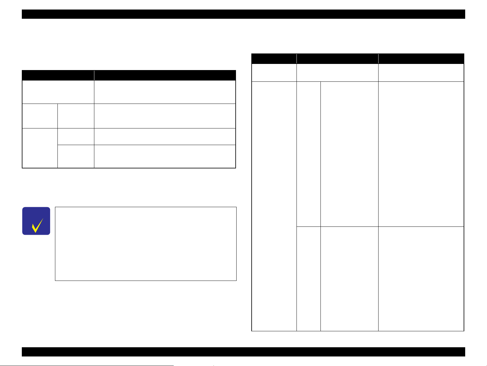
Epson Stylus NX510/SX410/SX210/NX420/NX220 series Revision B
1.7.3.2 Supported File Type and Media Type
The followings describe the file system, media format, and file type supported by the
memory card direct function.
Table 1-43. Supported File System, Types and Media Format
Item Specification
DCF Version 1.0 or 2.0 *1 compliant. Other than those does
File system
Media format Memory card
JPEG (*.JPG)
File type
Note *1: Refer to the Camera File System Standard; “DCF Version 2.0, JEIDA-CP-3461” for
*2 : FAT32 is not specified in the xD-Picture card standards; however, reading of xD-
C H E C K
P O I N T
Camera
definition file
(*.MRK)
more details.
Picture card formatted in FAT32 is supported. (NX510 series only)
The printer does not detect any files stored under the following
directories or their sub-directories.
• Directories containing system properties or hidden properties.
• “RECYCLED” (Windows directory for deleted files)
• “PREVIEW” (directories of CASIO DSC for thumbnail images)
• “SCENE” (directories of CASIO DSC for its Best Shot function)
• “MSSONY” (directories of SONY DSC for e-mail images, voice memos,
movies, or non-compressed images)
• “DCIM\ALBUM\IMAGE” (directories of CASIO DSC for its album
function)
not ensure proper operation. File systems available with the
card reader function are restricted by the host’s specification.
• DCF Version 1.0 or 2.0 compliant
• DOS FAT format (FAT12/FAT16/FAT32 *2) with single
partition (basic partitioned)
Image files conform to Exif Version 2.21. (Exif version 1.0/
2.0/2.1/2.2/2.21 are supported)
Camera definition files used for DPOF mode.
“\MISC\AUTOPRINT.MRK” file is valid.
1.7.3.3 Automatic Detection of Images in Memory Card
When a memory card is inserted in the card slot on the printer, or when a memory card
is detected at power-on, the printer automatically searches for all images stored in the
card. When the card is removed, the printer erases the information on the all detected
files.
1.7.3.4 Specifications for Handling Image Data
Table 1-44. Specifications for Handling Image Data
Item Specification Remarks
Image size (pixel)
Maximum
number of images
• Horizontal: 80 ≤ X ≤ 9200
• Vertical: 80 ≤ Y ≤ 9200
Up to 9,990 images When a memory card stores 9,990
NX510
series
Up to 999 images When a memory card stores 1,000
SX410/
SX210
series
or more images, the first 9,990
images are detected and become
valid in the printer. The detecting
order varies depending on the folder
configuration in the card, in such a
case, which images are included in
the 9,990 or not cannot be
guaranteed. In addition, the files
that can be handled are 9,990;
however, the files that can be
displayed on the LCD at a time are
999. When the existing files exceed
999, the files that are displayed
should be selected with UI. But,
images specified by camera
definition files can be selected to be
printed even when the total number
of images has exceeded 9,990. The
image files that can be specified are
limited up to 999.
or more images, the first 999
images are detected and become
valid in the printer. The detecting
order varies depending on the folder
configuration in the card, so which
images are included in the first 999
cannot be defined.
However, images specified by
camera definition files can be
selected to be printed even when the
total number of images has
exceeded 999. Up to 999 camera
defined image files can be
specified.
---
PRODUCT DESCRIPTION Specification for Each Function 40
Confidential
Page 40

Epson Stylus NX510/SX410/SX210/NX420/NX220 series Revision B
Table 1-44. Specifications for Handling Image Data
Item Specification Remarks
Maximum
number of copies
Valid date and
time
Thumbnail image
data
File sorting
99 copies for each image.
Up to 999 sheets in total.
01/01/1980 00:00:00 to
12/31/2099 23:59:59
Supports DCF Ver.1.0 or 2.0compatible data (Exif format,
160x120 pixels)
The printer sorts image files in
ascending ASCII order based on
their full-pathnames such as
“\DCIM\100EPSON\EPSN0000.J
PG”, and assigns a number to each
of them.
Thumbnail images are used for the
Print Index Sheet function.
• The image number assigned by
the printer may be different from
that assigned by the camera.
• If two or more files have the same
full pathname, the sorting
function may not operate
properly. (existence of the same
full-pathname is not allowed
under DOS)
---
---
Table 1-44. Specifications for Handling Image Data
Item Specification Remarks
Date and time
Acquisition of
date and time
information
NX510
series
SX410/
SX210
series
information applied on
DOS-compliant file
system.
The printer acquires
date and time
information included in
image files in the order
of precedence shown
below.
1. Shooting date and
time information in
digital camera
standard format
(Exif)
2. Digitized date and
time information in
digital camera
standard format
(Exif)
3. Date and time
information in
digital camera
standard format
(Exif)
4. Date and time
information applied
on DOS-compliant
file system.
5. Fixed date and time
information (01/01/
1980, 00:00:00)
Date and time information included
in an image file is not always the
shooting date and time. It changes
each time the image is edited and
restored. The printer acquires the
latest date and time information.
---
PRODUCT DESCRIPTION Specification for Each Function 41
Confidential
Page 41
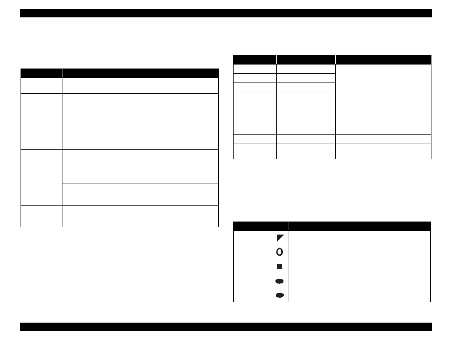
Epson Stylus NX510/SX410/SX210/NX420/NX220 series Revision B
1.7.3.5 Memory Card Direct Print Menu
The following describes the menu (settable items) in Memory Card Mode for NX510/
SX410 series. For SX210 series, only the Print Index Sheet function is available.
Table 1-45. Memory Card Mode Menu
Menu Item Function
View and Print
*1,3
Photos
Print All
*1,3
Photos
Print by Date
Print Index Sheet
(For SX210 series,
only this function is
available.
)
Slide Show
*4
Note *1: 0 to 99 copies can be specified for each of the images. Up to 999 copies in total.
*2 : For SX210 series, press the [Index Sheet] button to print the index sheet. All images
in a memory card are included in the sheet.
*3 : The images are listed in ASCII descending order.
*4 : While performing the slide show, displaying number of copies, printing from an
external device or from a computer cannot be made.
Prints the selected images.
Prints all images in a memory card. Specified number of copies is applied
to the all images (the default is 1 copy). Specifying it for each of the
images independently also can be made in the preview screen.
The date of the images are listed in the descending order with the number
of images by date. Selecting date from the list selects the images that has
*1
the selected date information. Specified number of copies is applied to the
selected images (the default is 1 copy). Specifying it for each of the
images independently also can be made in the preview screen.
Print Index Sheet
*2
Prints an index sheet that prints images in a memory card in thumbnailed
form. The number of images to be included in the sheet can be selected
from the following four options.
“All image” (default), “Latest 30”, “Latest 60”, “Latest 90”
Make Prints from Index Sheet
Scans the index sheet, and prints images according to markings written on
the sheet.
Starts a slide show on the LCD. Images in a memory card is displayed one
by one in the order sorted by the printer. Printing one of the images can be
made from the paused screen.
*3
1.7.3.6 Makes Prints from Index Sheet Function
Print settings
Table 1-46. Print Settings
Item Print Index Sheet Makes Prints from Index Sheet
Number of copies ---
Paper Type Plain paper
Paper Size A4, Letter
Layout ---
Quality Standard Standard
Expansion
Date
*1
--- Standard
YYYY.MM.DD
(2007.09.21)
*2
BiDirectional On On
Print Index Sheet
Setting-Select
According to the setting
*2
made by the control panel.
Note *1 : NX510 series only. SX410/SX210 series do not support it.
*2 : NX510/SX410 series only. SX210 series do not support it.
Rules on reading Index Sheet markings
The user can specify images to be printed and their print settings shown in Table
1-46 by putting marking on the Index Sheet. The printer reads the markings
according to the following rules.
Table 1-47. Rules on Reading Markings
Item
Left edge
(one each)
Right edge
(one each)
Block code
(36 pcs.)
Image selection
(30 pcs. x 3)
Paper type/size
(4 pcs.)
Mark
Description Remarks
Reference position for
reading markings.
Reference position for
reading markings.
Sheet information
(memory card, page)
Selects the image to be
printed.
Selects the paper type/size. An error occurs if two or more markings are
According to the marking on the index sheet.
According to the marking on the index sheet.
---
An error occurs if these markings cannot be
read due to ink stain or any other cause.
An error occurs if no image selection
marking is read.
read for one image.
PRODUCT DESCRIPTION Specification for Each Function 42
Confidential
Page 42

Epson Stylus NX510/SX410/SX210/NX420/NX220 series Revision B
<OK example> <NG example>
(not enough)
(too much)
Trimmed areas
Photo frame
(print area)
• When an image is aligned vertically with the photo frame.
• When an image is aligned horizontally with the photo frame.
Photo frame
(print area)
Trimmed
areas
Trimming On
Table 1-47. Rules on Reading Markings
Item
Layout (2pcs.) Selects the layout. An error occurs if two or more markings are
Date Prints the date information When this marking is read, the date is
Print all Select all the images If mark is recognized, print all the image
Note: • About 50% or more range of the mark area must be marked out to be read by the
printer.
• For running out and excessive marking out, the two white/black search patterns shown
above are superimposed on the mark, and judgement is made according to this
matching ratio.
• The judgement criteria is as follows;
black matching: 80% or more, white matching: 50% or more.
• The figure below shows the judgement example according to the rules described
above.
Mark
Description Remarks
read for one image. If no marking is read,
borderless layout is applied.
printed on the image.
one each.
Index Sheet errors
Index sheet scan error
(incorrect sheet setting)
Index sheet scan error
(incorrect image selection
marking)
Index sheet scan error
(incorrect paper selection
marking)
Index sheet scan error
(unmatch between memory
card and sheet)
Error Name Description
Table 1-48. Index Sheet Error List
The Index Sheet is not properly placed on the document glass.
Image selection markings are not correct.
Paper selection markings are not correct.
The memory card may have been changed or some images
may have been added or deleted after the Index Sheet is
printed.
1.7.3.7 Print Layout
The memory card direct print function supports two print layouts for printing images;
Borderless, and With Border. The Borderless layout is not allowed for some type of
paper (refer to Table 1-41 and Table 1-42). And see “ 1.2.5 Printing Area ” (p.23) for
information on the print area and margins of “Borderless” and “With Border” layouts.
Trimming Function
A trimming function is provided as a means of coordinating an image with the
types of photo frames handled by the printer. This function can be switched On/
Off. This function is described briefly below.
The printed photo frame and an image to be printed are matched in length along
one side and the image is resized along the perpendicular side to fit the frame on
that side. Any part of the image that does not fit within the photo frame is trimmed
away (not printed). However, if the number of pixels of the longer side of the
image are more than twice as long as the shortest side, the trimming function is not
effective when printing even the trimming is set. The trimming function is always
set On if borderless or upper half layout is selected.
Figure 1-9. Trimming Function (when trimming is being operated)
PRODUCT DESCRIPTION Specification for Each Function 43
Confidential
Page 43
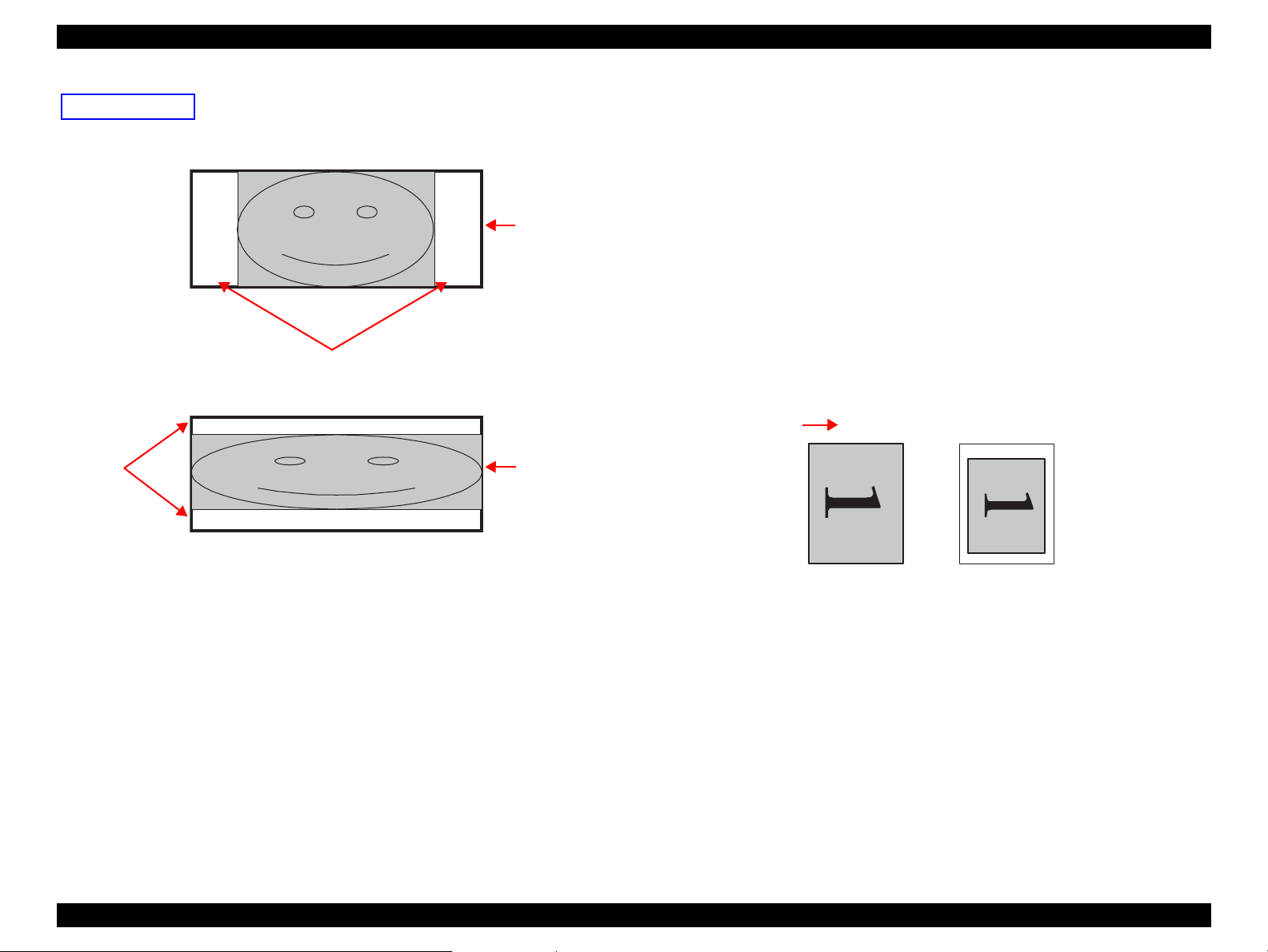
Epson Stylus NX510/SX410/SX210/NX420/NX220 series Revision B
Blank
area
Photo frame
(print area)
• When an image is aligned vertically with the photo frame.
• When an image is aligned horizontally with the photo frame.
Photo frame
(print area)
Blank area
Trimming Off
<Borderless> <With Border>
Paper top edge
Rules on Numbering and Rotating Images
The numbers shown in the figure below indicate the photo frame numbers used for
the print layout. Horizontally oriented images are printed as shown by the
numbers. Vertically oriented images, which has more pixels vertically than
horizontally, the vertical photo data is allocated instead, and the number shown in
the figure below is then rotated 90 degrees before being printed. In Index printing
mode, the numbers are printed as they are shown below, regardless of the shape of
the photo data.
However, when the photo data has an equal number of pixels vertically and
horizontally the photos are printed without rotation, regardless of the layout.
NOTE: The vertical photo data refers to when the photo data file itself is set for a
vertical (portrait) orientation. Photo data is defined as the vertical photo
data if it is taken by a digital camera with a portrait position detecting
function.)
Figure 1-10. Trimming Function (when trimming is not operated)
Figure 1-11. Rules on Numbering and Rotating Images
PRODUCT DESCRIPTION Specification for Each Function 44
Confidential
Page 44

Epson Stylus NX510/SX410/SX210/NX420/NX220 series Revision B
1.7.4 Camera Direct Print Function (PictBridge) (NX510/SX410 series only)
Printing operations (selecting images to be printed, making print settings, starting/
canceling printing, and monitoring print process) can be carried out from a directly
connected DSC (Digital Still Camera) that conforms to the standard described below.
1.7.4.1 Available DSC
Those devices which are compliant with "CIPA DC-001-2003 Digital Photo Solutions
for Imaging Devices" (DPS Version 1.0) or "CIPA DC-001-2003 Rev.2.0, Digital
Photo Solutions for Imaging Devices" (DPS Version 1.1).
1.7.4.2 Print Settings Available from DSC
The following print settings can be made from the DSC. However, depending on the
DSC, some of the settings may not be available.
Table 1-49. Print Settings Available from DSC
Item PictBridge
How to specify images Single Sheet / Multiple Sheet / DPOF specified
Paper type Plain Paper/ Prem. Glossy
Paper size 4 x 6, 5 x 7, Letter (EAI model only), A4, 16:9wide
Layout Borderless / With Borders
Date On / Off
Quality Not available
Auto Correct Not available
Fit to Frame Any range specified
Control of printer The following operations are available; Getting the printer status, starting
a print job or canceling it immediately or after printing the current page is
finished.
1.7.4.3 General Operation Procedure
C H E C K
P O I N T
The DSC direct print procedure differs depending on the DSC specifications.The
following explains common procedure.
1. Setting on the printer
Before connecting a DSC with a USB cable, make the print settings such as paper
type/size, layout setting on the printer. This may not be required for some DSCs.
2. Setting on the DSC
Make the following settings on the DSC before connecting it to the printer. Some
DSCs may require to first connect to the printer for making the settings.
3. Starting to print
When the print settings on both the printer and the DSC is completed, follow the
procedure below to start printing.
1. Connect the printer and the DSC with a USB cable. Using a USB cable
2. Operate the DSC to start printing.
3. Printing is carried out according to the settings made on the DSC. When some
Before connecting the DSC, check that the printer is in the
following status.
• No print job from a computer is processed or performed.
• Direct print from a memory card is not processed or performed.
• Stand alone copy using the scanner function is not operating.
• No paper out error or ink out error is occurring.
• When printing multiple images, specify images and number of copies using
the DPOF and Multiple Sheet menus. The menus may not be available on
some DSCs.
• When printing a single image
Specify an image and the number of copies. Specifying the number of
copies may not be available on some DSCs.
• Select the paper type/size, layout, and make the Fit to Frame setting if
necessary. These settings may not be available on some DSCs.
included in the DSC package is recommended.
print settings have not been made on the DSC, the corresponding settings
made on the printer are applied.
PRODUCT DESCRIPTION Specification for Each Function 45
Confidential
Page 45

Epson Stylus NX510/SX410/SX210/NX420/NX220 series Revision B
1.7.4.4 Operating Specifications during Connecting DSC
Table 1-50. Operations during Connecting DSC
Operation Specifications
Connecting
DSC
(print start)
Canceling
printing
After printing
is completed
Exclusion
control
If an DSC is connected in Step 3-(1) of “ 1.7.4.3 General Operation Procedure
( p. 45 ) ”, the PictBridge logo is displayed on the LCD.
A print job can be canceled from the DSC.
The [Stop/Clear setting] button also cancels the print job.
When performing memory card direct print after printing from a DSC, the
USB cable connecting the DSC must be disconnected from the printer in
advance.
Print settings made on both the DSC and the printer can become impossible
settings for the printer due to unsupported combination of paper type, paper
size and layout. In such case, the print settings are automatically changed as
follows.
The settings made on the DSC are maintained. Any print setting items that are
not specified by the DSC are changed in accordance with the DSC settings.
When the paper type is changed, changed to Prem. Glossy, when the paper
size is changed, changed to 4x6 size. And when the layout is changed,
changed to Borderless layout.
1.7.5 Reprint/Restore Photos Function (NX510 series only)
NX510 series offers the photo copy function. This function allows the user to copy
their silver halide film-based pictures. The printer scans the pictures automatically
detecting them as silver halide film-based picture, and makes a copy of them.
1.7.5.1 Supported Paper Type and Print Mode
Table 1-51. Paper Type and Print Mode
Paper Type Size Quality Resolution
Letter
Letter
*1
Standard
Standard
*1
Standard
*1
Standard
*1
1440x720 VSD3 ON ON
1440x720 VSD3 ON ON
1440x720 VSD3 ON ON
1440x720 VSD3 ON ON
Matte paper A4, Letter
Photo Paper
Prem. Glossy
Ultra Glossy
Note *1 : Letter size is supported for EAI only.
*2 : The Photo Paper 5x7 size is not supported for EAI.
4x6, 5x7*2,
A4, Letter
4x6, 5x7, A4,
4x6, 5x7, A4,
1.7.5.2 Reprint/Restore Photos Menu
Dot
size
Bi-D
Micro
Weave
Borde
rless
OK
OK
OK
OK
Table 1-52. Reprint/Restore Photos Menu
Items Function
Number of copies Sets the number of copies within the range of 1 to 99.
Paper type Selects paper type from the options shown in Table 1-51.
Paper size Selects paper size from the options shown in Table 1-51.
Selects print layout from the following three options:
Layout
Quality Fixed to “Standard“.
Expansion
Color restoration Selects from On or Off. The default is Off.
• Standard (normal layout with 3mm margins)
• Borderless (no margins)
Selects the margins level (margins bleed off the edges of paper)
from the Standard (100%), Mid. (50%) or Min. (25%).
PRODUCT DESCRIPTION Specification for Each Function 46
Confidential
Page 46

Epson Stylus NX510/SX410/SX210/NX420/NX220 series Revision B
Picture (2)
Picture (1)
5 mm or more
5mm
5mm
Home position
Scanning Direction
Document
Glass
1.7.5.3 How to Place Silver Halide Pictures
The following explains how to place silver halide film-based pictures on the document
glass of the printer.
Available picture size: 30x40 mm to 127x178mm (5”x7”)
Lay the pictures on the glass face down.
The number of pictures available at one time is as follows:
• 4x6 or smaller:up to 2 pictures
• 5x7: up to 1 picture
The following spaces are needed:
• 5 mm or more space from the right and front edges of the document glass.
• 5 mm or more space between pictures.
The pictures must not be tilted.
Figure 1-12. Laying Silver Halide Pictures
1.7.6 Setup Mode
NX510/SX410 series turns into the Setup mode by pressing the [Setup] button, and
each setting and maintenance become available. For SX210 series, simultaneously
pressing the [Index sheet] button and the [Scan] button provides the same function.
Table 1-53. NX510/SX410 series Common Setup Mode Menu
Item Function
The current ink levels are displayed in bar chart by the rules
described below. After displaying the ink levels, the next
operation can be selected from the following two options;
“OK” or “Replace Cartridge”.
• The bar chart is displayed in the order of black, magenta,
yellow, and cyan from the left.
Ink Cartridge Status
Maintenance
• When initial filling is completed, or after replacing the
cartridge, the ink level becomes 100% (full).
• The ink level is indicated in increment of 1%. Lower than
1% is rounded up.
• When the remaining ink level becomes lower than
approximately 10%, zero (ink low status) will be
displayed.
Runs various maintenance for the printer. The following
shows each menu.
• Nozzle Check
A nozzle check pattern to check the Printhead nozzles
status is printed. A head cleaning can be run if necessary.
(Refer to Figure 1-13, Figure 1-14 for Printout patterns.)
• Head Cleaning
Runs a printhead cleaning. The cleaning cannot be made
when low ink level is detected.
• Head Alignment
Adjustment to improve the bi-directional print quality.
Head alignment icon and the instructions for the
adjustment are displayed on the LCD.
• Cartridge Replacement
Runs an ink cartridge replacement sequence. This can be
done from the Ink Cartridge Status menu or by following
the instructions on the LCD when an ink-related error
occurs.
PRODUCT DESCRIPTION Specification for Each Function 47
Confidential
Page 47

Epson Stylus NX510/SX410/SX210/NX420/NX220 series Revision B
8
1
16
9
24
17
32
25
40
33
48
41
56
49
64
57
72
65
80
73
88
81
96
89
104
97
112
105
120
113
128
121
8
1
16
9
24
17
32
25
40
33
48
41
56
49
64
57
72
65
80
73
88
81
96
89
104
97
112
105
120
113
128
121
8
1
16
9
24
17
32
25
40
33
48
41
56
49
64
57
72
65
80
73
88
81
96
89
104
97
112
105
120
113
128
121
8
1
16
9
24
17
32
25
40
33
48
41
56
49
64
57
72
65
80
73
88
81
96
89
104
97
112
105
120
113
128
121
8
1
16
9
24
17
32
25
40
33
48
41
56
49
64
57
72
65
80
73
88
81
96
89
104
97
112
105
120
113
128
121
8
1
16
9
24
17
32
25
40
33
48
41
56
49
64
57
72
65
80
73
88
81
96
89
104
97
112
105
120
113
128
121
32 dots
360 dpi VSD1 dot
0.2117mm (1/120inch)
CyanMagenta
Yellow
Black Black Black
1
11
21
31
41
51
61
71
81
10
20
30
40
50
60
70
80
90
1
11
21
31
41
51
61
71
81
10
20
30
40
50
60
70
80
90
1
11
21
31
41
51
61
71
81
10
20
30
40
50
60
70
80
90
1
11
21
31
41
51
61
71
81
10
20
30
40
50
60
70
80
90
32 dots
360 dpi VSD1 dot
0.2117mm (1/120inch)
Cyan Magenta Yellow Black
Table 1-53. NX510/SX410 series Common Setup Mode Menu
Item Function
• Language
Sets the language.
•Display Format
Maintenance
PictBridge Setup
Restore Default Settings Restores the default settings of the panel settings.*
Note * : For NX510 series, the following items are settable.
• “All Settings”
• “Network Settings”
• ”All except Network”
Display format can be selected from the following three
types.
1-up with Info
1-up without Info
View Thumbnail Images
The print settings for the camera direct print (PictBridge)
can be selected and set. When print conditions (paper type,
paper size, layout, quality, and auto correct) are specified
from the DSC, the DSC settings take priority over the
settings made here. For details, refer to “ 1.7.4 Camera
Direct Print Function (PictBridge) (NX510/SX410 series
only) ( p. 45 ) ”.
Figure 1-13. Nozzle Check Pattern for NX510 series*
Figure 1-14. Nozzle Check Pattern for SX410 series*
Note* : The numbers shown in the figure are nozzle numbers. The numbers and the color names
are not printed on an actual nozzle check pattern.
PRODUCT DESCRIPTION Specification for Each Function 48
Confidential
Page 48

Epson Stylus NX510/SX410/SX210/NX420/NX220 series Revision B
㩻㩻㩷㪅㩷㩻㩻㩻㩻㩻㩻㩷㩷㩷㩷㩷㩻㩻㩷㩿㩷㪄㪄㪄㪄㩷㪆㩷㩻㩻㩻㩻㩻㩻㩻㩻㪀
㩻㩻㩻㩻㩻㩻㩻㩻
㩻㩻㩻㩻㩻㩻㩻㩻㩷㩷
㪘㫌㫋㫆㩷㩿㩷㪈㪇㪇㪙㪘㪪㪜㪄㪫㪯㪃㩷㪝㫌㫃㫃㩷㪛㫌㫇㫃㪼㫏㩷㪀㩷
㪘㫌㫋㫆㩷
㪦㪽㪽㩷
㩻㩻㩻㩻㩻㩻㩻㩻㩷
㩻㩻㩻㩻㩻㩻㩻㩻㩷㩷
㩻㩻㩻㩻㩻㩻㩻㩻㩷㩷
Table 1-54. Setup Mode Menu available only for NX510 series
Item Function
Changes settings for Network.
• Confirmation of Network Settings
Displays the current settings. Status Sheet can be printed.
(Refer to Figure 1-15.)
• Network Basic Settings
Network Settings
Select Location Change the group of photos to display.
Note* : When the network settings are changed, the network connection can be shut down
*
temporarily.
Changes settings for printer name and TCP/IP (auto/
manual).
• Wireless LAN Setting
Enabling/disabling Wireless LAN.
• File Sharing Setup
Changes settings of the files in a memory card for file
sharing via network.
Figure 1-15. Sample of Network Status Sheet
PRODUCT DESCRIPTION Specification for Each Function 49
Confidential
Page 49

Epson Stylus NX510/SX410/SX210/NX420/NX220 series Revision B
61
31
1
30
60
90
1
29
1
29
1
29
8 dots
360 dpi VSD1 dot
0.212mm (1/120inch)
Cyan
Magenta
Yellow
Black
Table 1-55. Setup Mode Menu for SX210 series
Item Function
A nozzle check pattern to check the Printhead nozzles status is
Nozzle Check
Head Cleaning
Head Alignment
Cartridge Replacement
Language Sets the language.
Restore Default Settings Restores the default settings of the panel settings.
printed. A head cleaning can be run if necessary. (Refer to
Figure 1-16.)
Runs a printhead cleaning. The cleaning cannot be made when
low ink level is detected. In such a case, an ink low error is
displayed instead of running the cleaning.
Adjustment to improve the bi-directional print quality. Head
alignment icon and the instructions for the adjustment are
displayed on the LCD.
Runs an ink cartridge replacement sequence. This can be done
from the Ink Cartridge Status menu or by following the
instructions on the LCD when an ink-related error occurs.
Figure 1-16. SX210 series の Nozzle Check Pattern
*
Note* : The numbers shown in the figure are nozzle numbers. The numbers and the color names
are not printed on an actual nozzle check pattern.
PRODUCT DESCRIPTION Specification for Each Function 50
Confidential
Page 50

OPERATING PRINCIPLES
CHAPTER
2
Confidential
Page 51

Epson Stylus NX510/SX410/SX210/NX420/NX220 series Revision B
Notation Product name
NX510 series Epson Stylus NX510/NX515/SX510W/SX515W/TX550W
SX410 series Epson Stylus NX415/SX410/SX415/TX410/TX419
SX210 series
Epson Stylus NX215/SX210/SX215/TX210/TX213/
TX219/ME OFFICE 510
NX420 series
Epson Stylus NX420/TX420W/SX420W/SX425W/Epson
ME OFFICE 560W
NX220 series
Epson Stylus TX220/NX220/SX218/TX228/Epson ME
OFFICE 520
Compression
Spring
LD Roller
Retard Roller
Change Lever
PE Sensor
PF Motor
Ink System
Carriage Unit
CR Encoder
Sensor
PF Roller
CR Timing Belt
EJ Roller
Star Wheel
PF Scale
PF Encoder Sensor
CR Motor
CR Scale
Cover Open Sensor
(NX510 series only)
2.1 Overview
C H E C K
P O I N T
This section describes the operating principles of the printer mechanism and the
electrical circuit board of this product.
2.1.1 Printer Mechanism
The printer mechanism of this product consists of the printhead, carriage mechanism,
paper loading mechanism, paper feed mechanism, and the ink system.
In this chapter, the product names are called as follows:
Description in this chapter is applied to NX510/SX410/SX210/
NX420/NX210 series. However, see below for the specifications
of the printhead and the power-on sequence of NX420/NX210
series.
• " 8.2 OPERATING PRINCIPLES" (p.190)
As the conventional models, this product is equipped with two DC motors; one is used
to drive the paper loading and paper feed mechanisms, and also the pump mechanism
that includes the carriage lock mechanism. The other one is used to drive the carriage
mechanism. Paper is fed from the rear at the ASF unit with the LD roller and Retard
roller, and ejected to the front at the tray.
OPERATING PRINCIPLES Overview 52
Figure 2-1. Printer Mechanism block diagram
Confidential
Page 52

Epson Stylus NX510/SX410/SX210/NX420/NX220 series Revision B
Printhead
PF Encoder Sensor
Cover Open Sensor
(NX510 series only)
CR Motor
CR Encoder Sensor
CR Contact Module
PF Motor
PE Sensor
2.1.2 Motors & Sensors
The printer mechanism of this product is equipped with the following printheads,
motors and sensors.
Table 2-1. Printer Mechanism Motors & Sensors
No. Name Specification
*1
*1
*1
*2
Figure 2-2. Motors & Sensors in Printer Mechanism
1 Printhead
2 CR Motor
3 PF Motor
4 PE Sensor
5 CR Contact Module CSIC board
6 CR Encoder Sensor
7 PF Encoder Sensor
Cover Open Sensor
8
(NX510 series only)
NX510 series O6-chips Turbo II head
SX410 series D4-chips Turbo II head
SX210 series/
NX220 series
NX420 series O2-chips Turbo II head
NX510 series
SX410 series/
SX210 series/
NX420 series/
NX220 series
Type: DC motor
Drive voltage: 42 VDC ± 5% (DRV IC voltage)
Coil resistance: 21.2 Ω ± 10%
Inductance: 17.2 mH (1 kHz)
Drive method: PWM, constant-current chopping
Purpose : Detection of paper top and bottom edge, for control to set
Type: Photo interrupter
Type: Photo interrupter
Resolution: 180 pulse/inch
Type: Photo interrupter
Resolution: 180 pulse/inch
Purpose: To detect the cover’s (scanner unit) open/close status
Type: Mechanical contact point
D2-chips Turbo II head
Type: DC motor
Drive voltage: 42 VDC ± 5% (DRV IC voltage)
Coil resistance: 22.7 Ω ± 10%
Inductance: 15.9 mH (1 KHz)
Drive method: PWM, constant-current chopping
Type: DC motor
Drive voltage: 42 VDC ± 5% (DRV IC voltage)
Coil resistance: 28.8 Ω ± 10%
Inductance: 20.1 mH (1 KHz)
Drive method: PWM, constant-current chopping
paper at the print start position
Note *1 : For the details of each printhead, see 2.1.3 "Printhead (p55) ".
*2 : For the details of the printhead, see 8.2.1 "Printhead (NX420 series) (p190) ".
OPERATING PRINCIPLES Overview 53
Confidential
Page 53
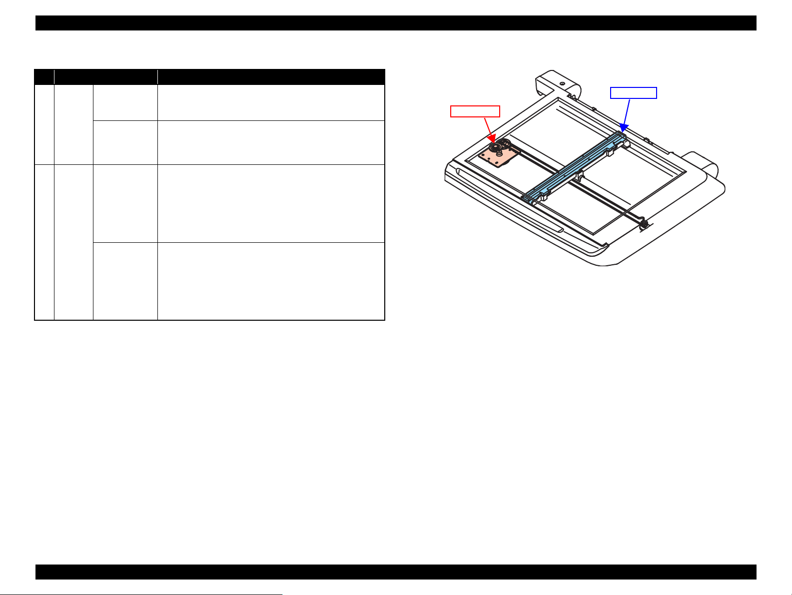
Epson Stylus NX510/SX410/SX210/NX420/NX220 series Revision B
CIS Unit
CR Motor
Table 2-2. Scanner Mechanism CIS & Motor
No. Name Specification
Resolution: 20,400 pixel
1 CIS Unit
CR
2
Motor
NX510 series
SX410 series/
SX210 series/
NX420 series/
NX220 series
NX510 series
SX410 series/
SX210 series/
NX420 series/
NX220 series
Black: 16 bit per pixel (input), 1 bit/ 8 bit per pixel (output)
Color: 48 bit per pixel (input), 24 bit per pixel (output)
Resolution: 10,200 pixel
Black: 16 bit per pixel (input), 8 bit per pixel (output)
Color: 48 bit per pixel (input), 24 bit per pixel (output)
Type: 2-phase 96-pole PM type stepping motor
Voltage: 42 VDC ± 5% (DRV IC voltage)
Coil resistance: 43 Ω ± 10% (OKI) / 38 Ω ± 10% (MITSUMI)
(at 25 oC)
Inductance:
Drive method: Bipolar fixed current drive
Type: 2-phase 96-pole PM type stepping motor
Voltage: 42 VDC ± 5% (DRV IC voltage)
Coil resistance: 43 Ω ± 10% (OKI) / 48 Ω ± 10% (MITSUMI)
Inductance:
Drive method: Bipolar fixed current drive
24.5 mH
±
20% (OKI) / 23 mH
(at 1 KHz, 1 Vrms)
(at 25 oC)
24.5 mH ± 20% (OKI) / 29 mH
(at 1 KHz, 1 Vrms)
±
20% (MITSUMI)
±
20% (MITSUMI)
Figure 2-3. CIS Unit and CR Motor in Scanner Mechanism
OPERATING PRINCIPLES Overview 54
Confidential
Page 54

Epson Stylus NX510/SX410/SX210/NX420/NX220 series Revision B
A#3
A#2
A#1
A#128
A#127
A#126
B#128
B#127
B#126
B#3
B#2
B#1
C#3
C#2
C#1
D#128
D#127
D#126
D#3
D#2
D#1
E#128
E#127
E#126
E#3
E#2
E#1
F#128
F#127
F#126
F#3
F#2
F#1
C#128
C#127
C#126
Paper feed direction
Carriage Moving Direction
Black
Yellow Magenta
Cyan
Paper feed direction
Carriage Moving Direction
Cyan
Magenta Yellow
Black
A#30
A#31
A#32
A#60
A#61
A#62
A#90
A#89
A#3
A#2
A#1
D#29
D#1
C#29
C#1
B#29
B#2
B#1
Paper feed direction
Carriage Moving Direction
Cyan
Magenta
Yellow
BlackColor
2.1.3 Printhead
Each model of this product employs a different type of printhead. The printhead configurations are as follows.
Table 2-3. Printheads of this product
Item NX510 series SX410 series SX210/NX220 series
Type O6-chips Turbo II head D4-chips Turbo II head D2-chips Turbo II head
Black 128 nozzles x 3 A/B/C column 90 nozzles x 1 D column 90 nozzles x 1 Black column A#1 - #90
Nozzle
configuration
Color
128 nozzles x 3 D column: yellow
E column: magenta
F column: cyan
90 nozzles x 3 A column: cyan
B column: magenta
C column: yellow
90 nozzles x 1 Color column
B#1 - #29: yellow
C#1 - #29: magenta
D#1 - #29: cyan
D#90
D#89
D#88
D#3
D#2
D#1
Nozzle layout
(as seen from behind the
printhead)
A#90
A#90
A#90
A#3
A#2
A#1
B#90
B#89
B#88
B#3
B#2
B#1
C#90
C#89
C#88
C#3
C#2
C#1
OPERATING PRINCIPLES Overview 55
Confidential
Page 55
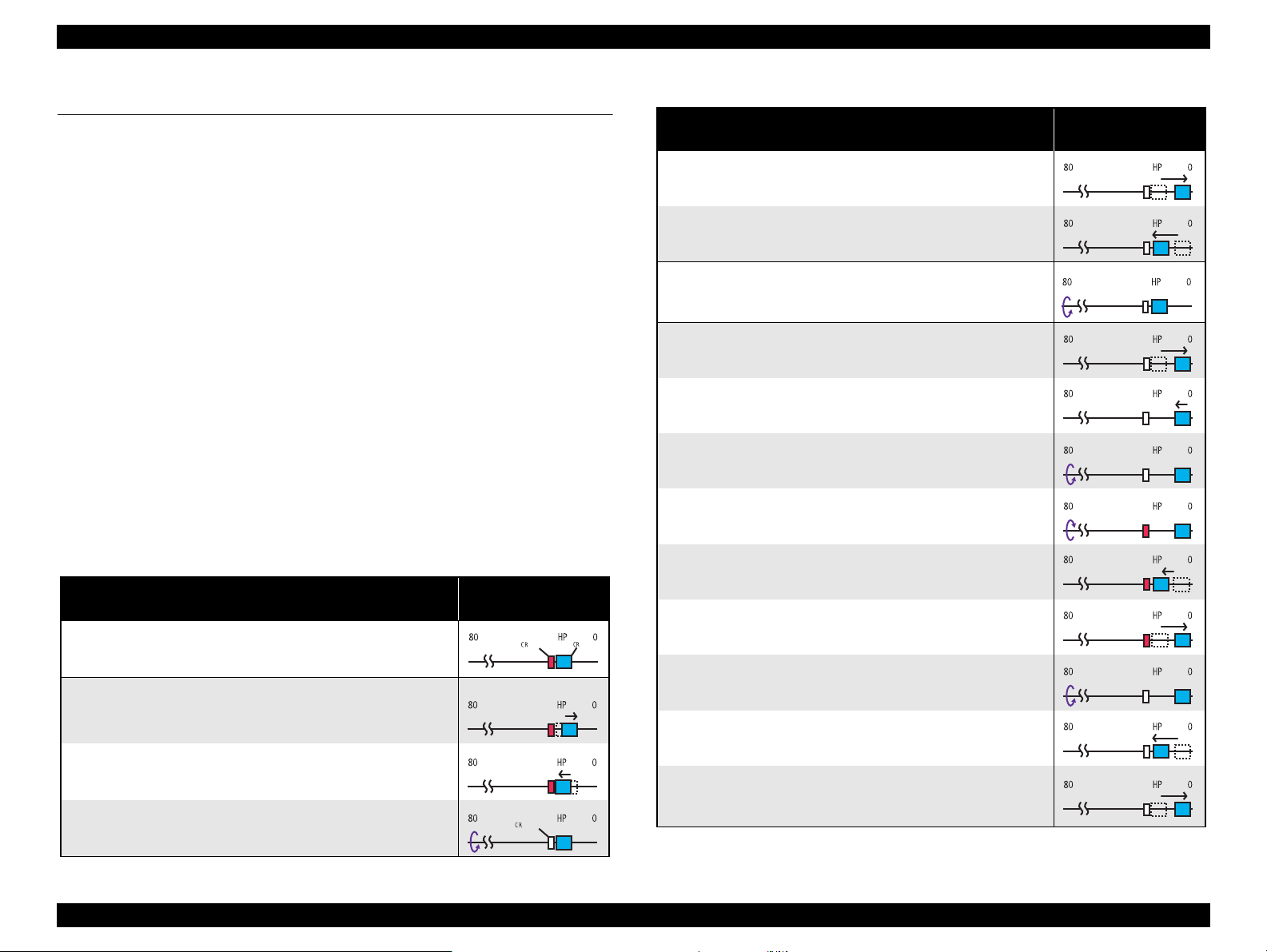
Epson Stylus NX510/SX410/SX210/NX420/NX220 series Revision B
lock
lockisreleased
2.2 Power-On Sequence
This section describes the power-on sequences in two conditions. The sequences for
these three series are basically similar with the exception of the CR lock setting
sequence (operation 8); therefore, they are described based on NX510 series in the
following conditions.
Condition 1: Normal power-on sequence (refer to Table 2-4)
Turning on the printer after turning it off without an error.
Completing ink charge.
No paper on the paper path.
The Printhead is capped with the Cap of the Ink System.
The Carriage is fixed by the CR Lock.
NOTE: For SX410/SX210 series, the CR lock setting sequence (operation 8)
differs from the sequence for NX510 series.
Condition 2: Power-on sequence after recovering from a paper jam error
(refer to Table 2-5)
Turning on the printer after turning it off with a paper jam error.
There still remains paper on the paper path out of the detecting area of the PE
sensor.
NOTE: For SX410 series, the detecting remaining paper sequence (operation 6)
is not implemented.
Table 2-4. Condition 1: Normal power-on sequence
Operation
1. Checking waste ink overflow
*1
Carriage/PF roller
movement and position
Table 2-4. Condition 1: Normal power-on sequence
Operation
2-4.The carriage moves to the 0-digit side slowly and confirms it
touches the Right Frame.
2-5.The carriage returns to its home position.
*1
3. Releasing the CR lock
3-1.The PF motor rotates clockwise, and releases the CR lock.
4. Seeking the home position
4-1.The carriage moves to the 0-digit side slowly and confirms it
touches the Right Frame.
4-2.The carriage slowly moves to the CR lock set position.
4-3.The PF motor rotates clockwise, and releases the CR lock.
4-4.The PF motor rotates counterclockwise, and sets the CR lock.
4-5.The carriage moves to the 80-digit side slowly and confirms it
touches the CR lock.
*2
4-6.The carriage slowly moves to the 0-digit side to the CR lock set
position.
Carriage/PF roller
movement and position
*2
4-7.The PF motor rotates clockwise, and releases the CR lock.
2. Avoiding deadlock sequence
2-1.The carriage moves to the 0-digit side slowly and confirms it
touches the CR lock.
2-2.The carriage slightly moves to the 80-digit side slowly.
2-3.The PF Motor rotates clockwise, and releases the CR lock.
OPERATING PRINCIPLES Power-On Sequence 56
*3
4-8.The carriage moves to the 80-digit side slowly and confirms it does
not touch the CR lock.
4-9.The carriage slowly moves to its original position, and the home
position is fixed.
Afterward, the carriage position is monitored according to the
signals from the CR Encoder.
Confidential
Page 56

Epson Stylus NX510/SX410/SX210/NX420/NX220 series Revision B
Table 2-4. Condition 1: Normal power-on sequence
Operation
5. Checking for remaining paper on the paper path and
measurement of the PF Motor
5-1.The carriage slowly moves to the ASF trigger position.
5-2.Checks if paper exists with the PE sensor*4 and the PF Motor rotates
clockwise for one second. (PF initialization)
5-3.The carriage slowly moves to the 0-digit side, then to the ASF
trigger holding position.
5-4.The PF motor rotates clockwise for two seconds, and performs the
load measurement.
*5
6. Low temperature operation sequence
6-1.The PF motor rotates clockwise, and releases the CR lock.
6-2.The carriage moves back and forth between the CR lock and the 80-
digit side for two times.
7. Detecting ink cartridge and initializing ink system
7-1.After rotating the PF motor clockwise to release the CR lock,
rotates the PF motor again clockwise for one second, and resets the
*8
PF roller.
7-2.After the carriage moves to the 80-digit side and checks the ink end
sensor, detects the ink remaining.
*1
*6
*7
Carriage/PF roller
movement and position
Table 2-4. Condition 1: Normal power-on sequence
*2
8-4.The carriage slowly returns to its home position.
Operation
*1
Note *1 : The rotation directions of the PF Motor are as follows.
Clockwise : Paper is fed normally
Counterclockwise : Paper is fed backward
*2 : The conditions of the CR lock are as follows.
Red : CR lock is set
White : CR lock is released
*3 : Confirms the carriage is not deadlocked such as the CR lock is caught in the gap of the carriage.
*4 : Eject paper if any.
*5 : When paper exists, the existing measurement value is read out, so the PF motor does not rotate.
*6 : Executed when the detected temperature is under 5 oC (41 oF) by the thermistor on the
Printhead.
*7 : The empty suction operation may occur depending on situations.
*8 : When paper remains in the printer, rotates the PF Roller until the paper is forcibly ejected.
*9 : For NX510 series, the CR lock is actually set at the beginning of power-saving mode
for enhancing throughput.
*10 :This operation is applied for NX510 series only.
Carriage/PF roller
movement and position
*2
7-3.The carriage quickly returns to its home position.
8. CR lock setting
8-1.The carriage slowly returns to its home position.
8-2.The carriage slowly moves to the CR lock set position.
8-3.The PF motor rotates counterclockwise, and sets the CR lock.
*9
*10
OPERATING PRINCIPLES Power-On Sequence 57
Confidential
Page 57

Epson Stylus NX510/SX410/SX210/NX420/NX220 series Revision B
Table 2-5. Condition 2: Power-on sequence after recovering from a paper jam error
Operation
Executes No.1 to No.5 on the normal power-on sequence (Table 2-4).
6. Detecting remaining paper
6-1.The carriage moves to the 80-digit side and confirms there is no
6-2.The carriage quickly returns to its home position, and displays on
When the user removes the paper and releases the paper jam error by panel operation, the normal poweron sequence from No.1 (Table 2-4) is executed again.*
Note : The power-on operations of SX410 series in condition 2 differs from the above
Note *1 : “Paper exists” is detected when the carriage touches the paper. When “paper does
*1
paper.
the LCD that the paper jam error occurs.
2
sequence since the detecting remaining paper sequence (operation 6) is not
implemented for SX410 series.
not exist” is detected, the power-on sequence of condition 1(Table 2-4) is executed
from No.6.
*2 : If the paper jam error cannot be solved after repeating the power-on sequence on
condition 2 (Table 2-5) twice, the printer turns into the paper jam fatal error for the
third time.
Carriage/PF Roller
movement and position
2.3 Printer Initialization
There are four kinds of initialization method, and the following explains each
initialization
1. Hardware initialization
This printer is initialized when turning the printer power on, or printer recognized
the cold-reset command (remote RS command).
When printer is initialized, the following actions are performed.
(a) Initializes printer mechanism
(b) Clears input data buffer
(c) Clears print buffer
(d) Sets default values
2. Operator initialization
Initialization when resetting the USB software, and the following are performed.
(a) Clears input data buffer
(b) Clears print buffer
(c) Sets default values
3. Software initialization
The ESC@ command also initialize the printer.
When printer is initialized, the following actions are performed.
(a) Clears print buffer
(b) Sets default values
4. IEEE 1284.4 “rs” command initialization
The printer recognized the IEEE 1284.4 “rs” command.
When printer is initialized, the following action is performed.
Initialization when an error occurs.
(a) Initializes printer mechanism
(b) Clears input data buffer
(c) Clears print buffer
(d) Sets default values
Initialization in normal operation
(a) Clears input data buffer
(b) Clears print buffer
(c) Sets default values
OPERATING PRINCIPLES Printer Initialization 58
Confidential
Page 58

TROUBLESHOOTING
CHAPTER
3
Confidential
Page 59

Epson Stylus NX510/SX410/SX210/NX420/NX220 series Revision B
Notation Main Board Power Supply Board
NX510 series CA48 MAIN
C687 PSE/PSB
SX410 series CA20 MAIN
SX210 series
CA47 MAIN
NX220 series
NX420 series CA80 MAIN
Notation Product name
NX510 series Epson Stylus NX510/NX515/SX510W/SX515W/TX550W
SX410 series Epson Stylus NX415/SX410/SX415/TX410/TX419
SX210 series
Epson Stylus NX215/SX210/SX215/TX210/TX213/
TX219/ME OFFICE 510
NX420 series
Epson Stylus NX420/TX420W/SX420W/SX425W/Epson
ME OFFICE 560W
NX220 series
Epson Stylus TX220/NX220/SX218/TX228/Epson ME
OFFICE 520
3.1 Overview
This chapter describes how to solve problems.
To avoid electric shocks, be careful when checking the electrical
N GW A R N I
circuit boards below while the power is on.
Touching an FET, transistor or heat sink with one hand while
touching a metal part of the mechanism with the other hand
could result in an electric shock, so carefully avoid this.
After initial filling of ink has been repeated several times,
immediate moving or tilting of the printer could result in
leaking of ink that has not been completely absorbed by the
Waste Ink Pad. When initial filling of ink has been repeated
several times, check the ink remaining in the tip of the Waste
Ink Tube and the waste ink not absorbed by the Waste Ink Pad
before moving the printer.
C H E C K
P O I N T
Disassembly and reassembly of parts is often required when
identifying the causes of problems. The parts should be
disassembled and re-assembled correctly while referring to
“DISASSEMBLY/ASSEMBLY” (p.95) so that the operation
and status of each check item can be correctly verified.
Some individual part and units may require adjustment once
they are removed or replaced. If removing or replacing parts
which have specific instructions for adjustment included in
“DISASSEMBLY/ASSEMBLY” (p.95), be sure to make these
adjustments after repairing the problem location.
In this chapter, the product names are called as follows:
Basically, description of this chapter is based on NX510/SX410/
SX210 series, but the remedies and instructions in the
checkpoints can be applied to NX420/NX220 series in the same
manner. For NX420 series; however, the number and the
location of the connectors on the Main Board differ from those
for other models. Therefore, use the number and the location of
the connectors as appropriate for NX420 series.
• " 8.3 TROUBLESHOOTING" (p.193)
TROUBLESHOOTING Overview 60
Confidential
Page 60

Epson Stylus NX510/SX410/SX210/NX420/NX220 series Revision B
3.1.1 Specified Tools
This printer does not require any specified tools for troubleshooting.
3.1.2 Preliminary Checks
Before starting troubleshooting, be sure to verify that the following conditions
are all met:
The power supply voltage must be within the specification limits. (Measure the
voltage at the wall socket.)
The power code must be free from damage, short circuit or breakage, or miswiring
in the power code.
The printer must be grounded properly.
The printer should not be located in a place where it can be exposed to too high or
low temperature, too high or low humidity, or abrupt temperature change.
The printer should not be located near waterworks, near humidifiers, near heaters
or near flames, in a dusty atmosphere or in a place where the printer can be
exposed to blast from an air conditioner.
The printer should not be located in a place where volatile or inflammable gases
are produced.
The printer should not be located in a place where it can be exposed to direct rays
of the sun.
The printer must be placed on a strong and steady level table (without an
inclination larger than five degrees).
Any vibrating equipment must not be placed on or under the printer.
The paper used must conform to the specification.
There is no error in handling of the printer.
Check the inside of the printer, and remove foreign matters if any, such as paper
clips, staples, bits of paper, paper dust or toner.
Clean the inside of the printer and the rubber rolls.
TROUBLESHOOTING Overview 61
Confidential
Page 61

Epson Stylus NX510/SX410/SX210/NX420/NX220 series Revision B
3.2 Troubleshooting
3.2.1 Motor and Sensor Troubleshooting
Motors
The resistance values for the CR motor and the PF motor are given below, however, the
values cannot be used to check the motors status since they are DC motor and the
resistance between the electric poles varies. Visually check the motors for abnormal
operation and if it is hard to judge, replace the motor.
NX510 series
Table 3-1. Motor resistance and check point (NX510 series)
Motor Motor Type Drive Voltage Resistance
PF motor
CR motor 22.7Ω ± 10%
Scanner motor
Note *1 : Manufactured by Oki Electric Industry Co., Ltd.
*2 : Manufactured by MITSUMI ELECTRIC CO., LTD.
DC motor with brush
DC 42V ± 5%
2-phase, 96-pole PM
stepping motor
SX410/SX/210/NX420/NX220 series
21.2Ω ± 10%
43.0Ω ± 10%*1 or
38.0Ω ± 10%
*2
Sensors
NX510 series
Table 3-3. Sensor check point (NX510 series)
Sensor name Check point Signal level Switch mode
PE Sensor CN15/Pin 1 and 2
Cover Open
Sensor
CN16/Pin 1 and 2
Less than 0.4V Off: No paper
More than 2.4V On: Detect the paper
Less than 0.4V Off: Cover Close
More than 2.4V On: Cover Open
SX410/SX210/NX220 series
Table 3-4. Sensor check point (SX410/SX210/NX220 series)
Sensor name Check point Signal level Switch mode
PE Sensor CN24/Pin 1 and 2
Less than 0.4V Off: No paper
More than 2.4V On: Detect the paper
Table 3-2. Motor resistance and check point
(SX410/SX210/NX420/NX220 series)
Motor Motor Type Drive Voltage Resistance
PF motor
CR motor 28.8Ω ± 10%
Scanner motor
Note *1 : Manufactured by Oki Electric Industry Co., Ltd.
*2 : Manufactured by MITSUMI ELECTRIC CO., LTD.
DC motor with brush
DC 42V ± 5%
2-phase, 96-pole PM
stepping motor
21.2Ω ± 10%
43.0Ω ± 10%*1 or
48.0Ω ± 10%
*2
TROUBLESHOOTING Troubleshooting 62
Confidential
Page 62

Epson Stylus NX510/SX410/SX210/NX420/NX220 series Revision B
3.3
Error Indications and Fault Occurrence Causes
This section explains error/warning messages indicated when an error occurs at each sequence/operation (power-on, paper loading/feeding, ink suction, etc.) and their error causes.
3.3.1 Error Message List
Table 3-5. Error Indications and Fault Occurrence Causes
LCD Message
Error Name
NX510 series SX410 series
SX210/NX420/
NX220 series
STM3 Message Error Cause Reference
Fatal error
(scanner)
Fatal error
(printer mechanism)
Maintenance error
(waste ink overflow)
Paper jam error
Ink cartridges error Cannot recognize ink cartridges.
Ink cartridge cover
open error
Replace Ink Cartridge Press the OK button to replace the ink cartridges. The ink is expended.
A scanner error has occurred. See your
documentation.
A printer error has occurred. Turn off the printer,
then press On button to turn on. See your
documentation.
The printer’s ink pads
are at the end of their
service life.
Please contact Epson
Support.
Paper jam. Open the scanner unit and remove the
paper.
Press the Start Button to eject the paper inside. See
you documentation.
Ink cartridge cover is open.
Open the scanner unit and close the ink cartridge
cover.
Waste ink pad in the
printer is saturated.
Contact your dealer to
replace it.
Scanner error has
occurred.
Printer error has
occurred.
Ink pads need service.
Contact Epson.
Paper jam. Remove
jammed paper.
Ink cartridges not
recognized.
Close cartridge cover.
Turn the printer off and delete all print jobs.
Open the scanner unit and remove any paper
from inside the printer and turn the printer back
on.Click the [How to] button for instructions on
removing jammed paper.
The printer's ink pads are at the end of their
service life. Please contact Epson support.
Click the [How to] button for instructions on
removing jammed paper.
Black: XXXX
Color: XXXX
…………
Epson recommends the genuine Epson
cartridges listed above. Click the [How to]
button for ink cartridge installation instructions.
Black: XXXX
Color: XXXX
…………
*4
Epson recommends the genuine Epson
cartridges listed above. Click the [How to]
button for ink cartridge replacement
instructions.
*1
*1
*1
*1
Scanner error occurs.
Mechanical trouble occurs.
The waste ink counter exceeds
to capacity.
Paper stays in the paper path
after paper ejection.
Ink is out in some I/C or no
I/C is set or incorrect I/C is set.
Table 3-6.
(p66)
Table 3-7.
(p72)
Table 3-8.
(p72)
Table 3-9.
(p75)
TROUBLESHOOTING Error Indications and Fault Occurrence Causes 63
Confidential
Page 63

Epson Stylus NX510/SX410/SX210/NX420/NX220 series Revision B
Table 3-5. Error Indications and Fault Occurrence Causes
LCD Message
Error Name
Paper out error
Double feed error
Memory card error Cannot recognize the memory card or disk.
Index sheet error 1
(No index sheet)
NX510 series SX410 series
Paper out.
Load paper and press the Start button.
Multi-page feed error.
Remove and reload the paper, then press the Start
button.
There is no index sheet or it is not positioned
correctly. Check it and try again.
SX210/NX420/
NX220 series
Paper out Load paper.
Multi-page feed error.
Memory card not
recognized.
No Index Sheet on
scanner.
Reload the paper, then press the Start button on
the printer or click the [Continue] button if it
appears on the screen. To cancel the print job,
click the [Cancel] button.
A page has not been printed, multiple pages
have been fed into the printer at once, or the
wrong paper size has been fed into the printer.
Remove and reload the paper. Press the Start
button if necessary.
STM3 Message Error Cause Reference
Table 3-10.
(p76)
Table 3-18.
(p80)
Table 3-13.
(p78)
Table 3-14.
(p79)
--
--
Failure to load paper to print.
Double feed during double
sided printing.
That memory card is not
available with this unit. Or no
image can be found in that card
when memory card print is
started.
The direction of order sheet is
opposite.
No index sheet is recognized
correctly.
Index sheet error 2
(Image marking error)
Index sheet error 3
(Paper marking error)
Index sheet error 4
(Incorrect card)
DSC Direct error
Photos are not selected or the ovals are marked
incorrectly. Please correct and try again.
The paper type is not selected or the ovals are
marked incorrectly. Please correct and try again.
The contents of the memory card have changed.
Print a new index sheet and try again.
*2
Cannot recognize the device. N/A --
No photos selected. --
Select paper type. --
Memory card does not
match Index Sheet.
--
When there is a mismatch in the
content of the order sheet
(When it is not marked though
the selection is necessary.)
The different card or updated
card is found for that sheet.
A device not supported is
connected to the port for the
connection of external memory
devices.
The DSC demands the current
larger than mechanical limit.
Table 3-15.
(p79)
Table 3-16.
(p79)
Table 3-12.
(p78)
TROUBLESHOOTING Error Indications and Fault Occurrence Causes 64
Confidential
Page 64

Epson Stylus NX510/SX410/SX210/NX420/NX220 series Revision B
Table 3-5. Error Indications and Fault Occurrence Causes
LCD Message
Error Name
Head cleaning
(Ink low error)
NX510 series SX410 series
Replace ink cartridge before cleaning Printhead.
SX210/NX420/
NX220 series
Replace ink before
cleaning.
Black: XXXX
Color: XXXX
....
You may continue printing, or click the [How
to] button to change the ink cartridge now.
STM3 Message Error Cause Reference
*1
*1
Head cleaning was attempted in
the Ink low status.
Table 3-11.
(p78)
Pre-scanning error
*2
(photo)
No photos could be recognized. Make sure the
photos are positioned correctly. See your
documentation.
Communication error --
Scanner unit open
*3
error
Network error
*3
Close the Scanner unit. N/A N/A Close the scanner unit.
-- N/A N/A --
Unknown error --
Note *1 : The “XXXX” represents the part number of the Ink Cartridge.
*2 : NX510/SX410 series only.
*3 : NX510 series only.
*4 : NX420 series only. "You need to replace ink cartridge(s)" is displayed.
N/A -- Photos cannot be recognized.
Check all connections and make sure all devices
are on. If the power was turned off during
printing, cancel the print job. If the error does
not clear, see your printer documentation.
The printer cannot
communicate with the PC
properly.
Scanner unit was opened during
printing.
A network related error
occurred.
Turn the printer off, and remove any jammed
paper. After a few minutes, turn the printer back
An unexpected error occurred. --
on. Please wait.
Table 3-17.
(p80)
Table 3-19.
(p81)
Table 3-20.
(p84)
“ 3.4 Network
Troubleshooti
ng (NX510/
NX420 series
only) ” (p.93)
TROUBLESHOOTING Error Indications and Fault Occurrence Causes 65
Confidential
Page 65

Epson Stylus NX510/SX410/SX210/NX420/NX220 series Revision B
NX510 series
CN8
SX410/SX210 series
CN10
Scanner Motor cable
Scanner Motor Connector Cable
3.3.2 Troubleshooting by Error Message
The following tables provide troubleshooting procedures. Confirm the error message indicated on the LCD or the STM3 screen on the PC’s display, and verify it in the following list
and the figures at the end of this chapter for the corresponding troubleshooting remedy. If some parts need to be replaced or repaired, make sure to follow the procedure given in
Chapter 4 “Disassembly / Assembly”.
Table 3-6. Check point for Fatal error according to each phenomenon
Occurrence
timing
CR position
Detailed phenomenon
Defective
unit/part name
Check point Remedy
1. Check if the Scanner Motor cable is connected to the
connector on the Main Board Unit shown below.
NX510 series: CN8
SX410/SX210 series: CN10
1. Connect the Scanner Motor cable to the
connector on the Main Board Unit shown
below.
NX510 series: CN8
SX410/SX210 series: CN10
• Power on
• Anywhere
TROUBLESHOOTING Error Indications and Fault Occurrence Causes 66
The Scanner Unit does not initialize when
the power is turned on.
Scanner Motor
2. Check the coil resistance with a tester if it matches the
2. Replace the Scanner Motor with a new one.
following value.(refer to Table 3-1).
NX510 series: Approx. 43Ω*
SX410/SX210/
1
or 38Ω*
NX420/NX220 series: Approx. 43Ω*1 or 48Ω*
Note *1 : Manufactured by Oki Electric Industry Co., Ltd.
*2 : Manufactured by MITSUMI ELECTRIC CO., LTD.
2
2
3. Check if the Scanner Motor Connector Cable is damaged. 3. Replace the Scanner Motor with a new one.
Confidential
Page 66
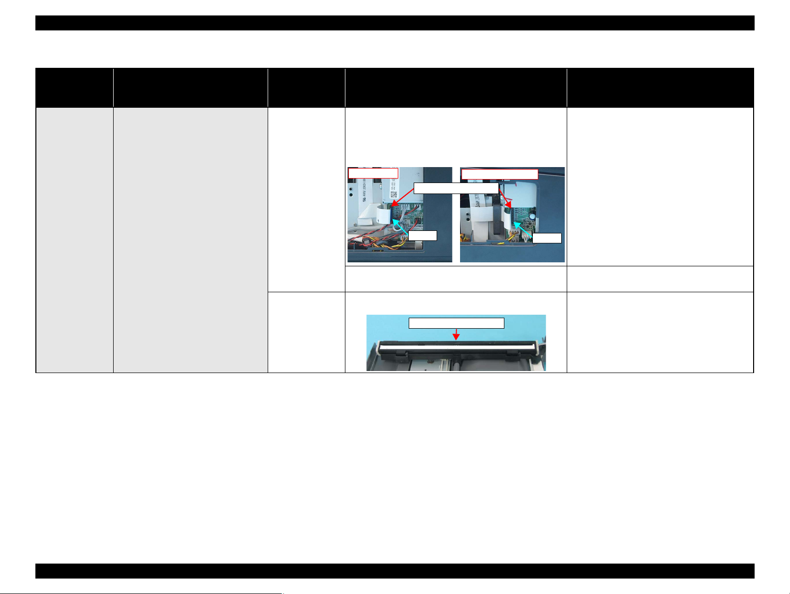
Epson Stylus NX510/SX410/SX210/NX420/NX220 series Revision B
NX510 series
CN17
SX410/SX210 series
CN21
Scanner Carriage FFC
Scanner Carriage Unit
Table 3-6. Check point for Fatal error according to each phenomenon
Occurrence
timing
CR position
Detailed phenomenon
Defective
unit/part name
Scanner Carriage
FFC
Check point Remedy
1. Check if the Scanner Carriage FFC is connected to the
connector on the Main Board Unit shown below.
NX510 series: CN17
SX410/SX210 series: CN21
1. Connect the Scanner Carriage FFC to the
connector on the Main Board Unit shown
below.
NX510 series: CN17
SX410/SX210 series: CN21
• Power on
• Anywhere
The Scanner Unit does not initialize when
the power is turned on.
2. Check if the Scanner Carriage FFC is damaged. 2. Replace the Scanner Carriage FFC with a new
one.
1. Check if the Scanner Carriage Unit is damaged. 1. Replace the Scanner Carriage Unit with a new
one.
Scanner Carriage
Unit
TROUBLESHOOTING Error Indications and Fault Occurrence Causes 67
Confidential
Page 67
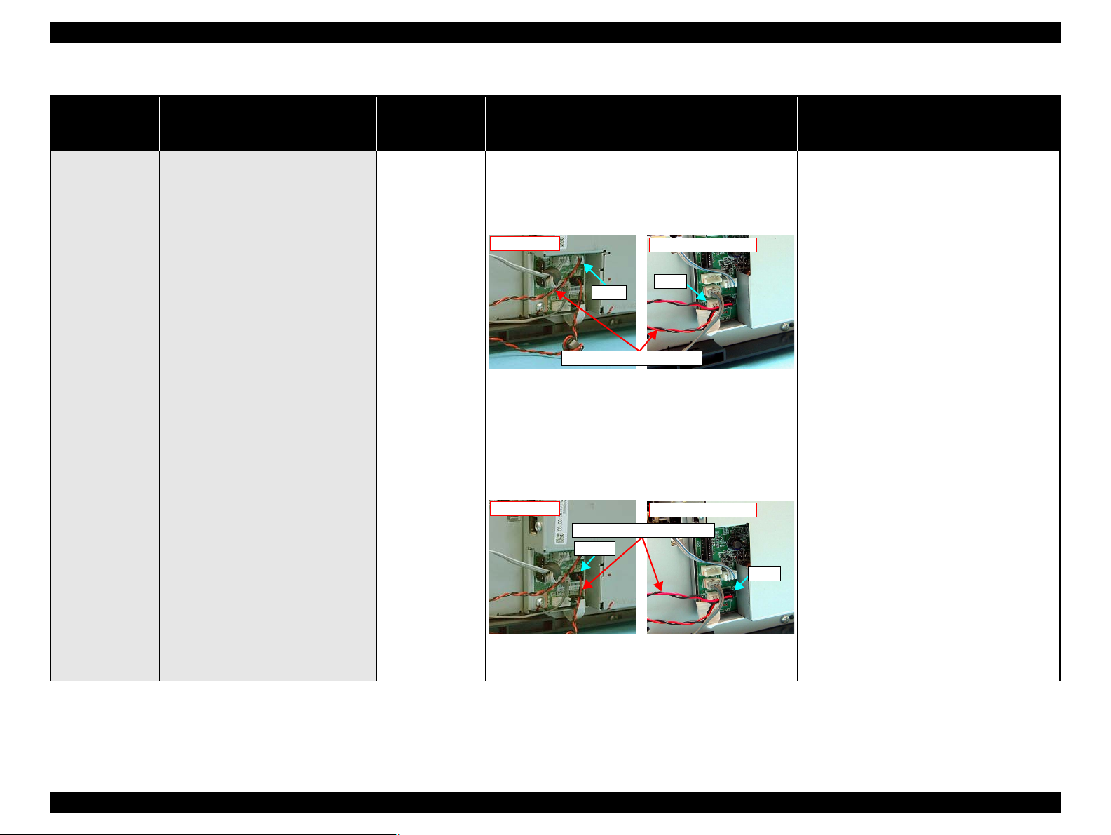
Epson Stylus NX510/SX410/SX210/NX420/NX220 series Revision B
NX510 series
CN6
SX410/SX210 series
CN8
CR Motor Connector Cable
NX510 series
CN7
SX410/SX210 series
CN9
PF Motor Connector Cable
Table 3-6. Check point for Fatal error according to each phenomenon
Occurrence
timing
CR position
Detailed phenomenon
Defective
unit/part name
Check point Remedy
1. Check if the CR Motor Connector Cable is connected to
the connector on the Main Board Unit shown below.
NX510 series: CN6
SX410/SX210 series: CN8
1. Connect the CR Motor Connector Cable to the
connector on the Main Board Unit shown
below.
NX510 series: CN6
SX410/SX210 series: CN8
• Power on
• Anywhere
When turning on the power, the CR
Motor does not operate at all.
When turning on the power, the PF Motor
does not operate at all
CR Motor
PF Motor
2. Check if the CR Motor Connector Cable is not damaged. 2. Replace the CR Motor with a new one.
3. Check if the CR Motor operates. 3. Replace the CR Motor with a new one.
1. Check if the PF Motor Connector Cable is connected to
the connector on the Main Board Unit shown below.
NX510 series: CN7
SX410/SX210 series: CN9
1. Connect the PF Motor Connector Cable to the
connector on the Main Board Unit shown
below.
NX510 series: CN7
SX410/SX210 series: CN9
2. Check if the PF Motor Connector Cable is not damaged. 2. Replace the PF Motor with a new one.
3. Check if the PF Motor operates. 3. Replace the PF Motor with a new one.
TROUBLESHOOTING Error Indications and Fault Occurrence Causes 68
Confidential
Page 68

Epson Stylus NX510/SX410/SX210/NX420/NX220 series Revision B
Compression Spring 2.36
Change Lever
Upper Paper Guide Unit
Table 3-6. Check point for Fatal error according to each phenomenon
Occurrence
timing
CR position
• Power on
• Anywhere
Detailed phenomenon
When turning on the power, the Carriage
Unit collides to the Change Lever located
to the front side of the printer.
Defective
unit/part name
PF Motor
ASF Unit
Check point Remedy
1. Check if the PF Motor Connector Cable is connected to
the connector on the Main Board Unit shown below.
NX510 series: CN7
SX410/SX210 series: CN9.
2. Check if the PF Motor Connector Cable is not damaged. 2. Replace the PF Motor with a new one.
3. Check if the PF Motor operates. 3. Replace the PF Motor with a new one.
1. Check if the Compression Spring 2.36 does not come off
in the Change Lever.
1. Connect the PF Motor Connector Cable to the
connector on the Main Board Unit shown
below.
NX510 series: CN7
SX410/SX210 series: CN9
1. Replace the ASF Unit with a new one.
TROUBLESHOOTING Error Indications and Fault Occurrence Causes 69
The Carriage Unit collides with the Upper
Paper Guide Unit when power is turned
on.
Upper Paper Guide
Unit
1. Check if the Paper Guide Upper Unit is correctly
assembled.
1. Reassemble the Upper Paper Guide Unit to the
Main Frame correctly.
Confidential
Page 69

Epson Stylus NX510/SX410/SX210/NX420/NX220 series Revision B
Slit of the CR Encoder Board
CR Scale
CR Encoder BoardEncoder FFC
Table 3-6. Check point for Fatal error according to each phenomenon
Occurrence
timing
CR position
Detailed phenomenon
Defective
unit/part name
CR Scale
Check point Remedy
1. Check if the CR Scale does not come off or it properly
passes through the slit of the CR Encoder Board.
2. Check if the CR Scale is not damaged or contaminated. 2. Replace the CR Scale with a new one or clean it
1. Reassemble the CR Scale correctly.
* If the problem is not solved, replace the Main
Board with a new one.
completely.
• Power on
• Anywhere
TROUBLESHOOTING Error Indications and Fault Occurrence Causes 70
When turning on the power, the Carriage
Unit collides to the right side of the Main
Frame.
CR Encoder Board
1. Check if the Encoder FFC is connected to the CR
Encoder Board.
2. Check if the Encoder FFC is not damaged. 2. Replace the Encoder FFC with a new one.
3. Check if the CR Encoder Board is not damaged. 3. Replace the CR Encoder Board with a new one.
1. Connect the Encoder FFC to the CR Encoder
Board.
Confidential
Page 70

Epson Stylus NX510/SX410/SX210/NX420/NX220 series Revision B
PF Scale PF Encoder Sensor
NX510 series
CN15
SX410/SX210 series
CN24
PE Sensor Connector Cable
Table 3-6. Check point for Fatal error according to each phenomenon
Occurrence
timing
CR position
Detailed phenomenon
Defective
unit/part name
Check point Remedy
1. Check if the PF Scale is not damaged or contaminated. 1. Replace the PF Scale with a new one.
• Power on
• Anywhere
• Operation
• Anywhere
The eject rollers are rotating at high speed
when power is turned on. (For about 1
cycle.)
The Scanner Carriage Unit does not
operate.
A paper feeding sequence failed to feed
the paper, but a paper ejection sequence is
performed.
PF Scale/PF
Encoder Sensor
Lower Scanner
Housing
ASF Unit
2. Check if the PF Encoder Sensor is not damaged. 2. Replace the PF Encoder Sensor with a new one.
1. Check if the grease is applied enough on the surface of
the Guide Rail of the Lower Scanner Housing.
1. Apply the grease on the surface of the Guide
Rail of the Lower Scanner Housing after wiping
the old grease with a dry, soft cloth. (Refer to
Chapter 6 “MAINTENANCE” (p.179))
2. Check if the Scanner Carriage Unit is set correctly. 2. Reassemble the Scanner Carriage Unit.
1. Check if the PE Sensor Connector Cable is connected to
the connector on the Main Board Unit shown below.
NX510 series: CN15
SX410/SX210 series: CN24
1. Connect the PE Sensor Connector Cable to the
connector on the Main Board Unit shown
below.
NX510 series: CN15
SX410/SX210 series: CN24
TROUBLESHOOTING Error Indications and Fault Occurrence Causes 71
2. Check if the PE Sensor Connector Cable is not damaged. 2. Replace the ASF Unit with a new one.
3. Check if the PE Sensor is not damaged. 3. Replace the ASF Unit with a new one.
Confidential
Page 71

Epson Stylus NX510/SX410/SX210/NX420/NX220 series Revision B
Paper Back Lever
Extension Spring 0.099
Extension Spring Retard
Backside of ASF Unit
Table 3-7. Check point for the Maintenance request according to each phenomenon
Occurrence
timing
CR position
• Operation
• –
Detailed phenomenon
An error is indicated on the LED and
STM or LCD.
Defective
unit/part name
Waste Ink Pads ---
Check point Remedy
1. Change the Waste Ink Pads and initialize the
Waste Ink Pad Counter. (Refer to Chapter 5
“ADJUSTMENT” (p.165))
Table 3-8. Check point for Paper jam error according to each phenomenon
Occurrence
timing
CR position
Detailed phenomenon
A paper feeding sequence failed to feed
the paper, but a paper ejection sequence is
performed.
Defective
unit/part name
ASF Unit
Check point Remedy
1. Check if the ASF Unit is properly installed. 1. Install the ASF Unit properly.
2. Check if the Paper Back Lever operates correctly in the
paper loading sequence.
2. Set the Extension Spring 0.099 between the
ASF Frame and the Paper Back Lever.
• Operation
• Outside HP
TROUBLESHOOTING Error Indications and Fault Occurrence Causes 72
Paper is being resent during paper feeding
operation.
ASF Unit
1. Check if the Extension Spring Retard operates correctly
in the paper loading sequence.
1. Set the Extension Spring Retard between the
Retard Roller Unit and the ASF Frame.
Confidential
Page 72

Epson Stylus NX510/SX410/SX210/NX420/NX220 series Revision B
Star Wheel Holder Assy
Star Wheel Holders
EJ Roller Unit
Table 3-8. Check point for Paper jam error according to each phenomenon
Occurrence
timing
CR position
Detailed phenomenon
Defective
unit/part name
Star Wheel Holder
Assy*
Check point Remedy
1. Check if the Star Wheel Holder Assy is correctly
assembled.
2. Check if the Star Wheel Holders does not come off. 2. Reassemble the Star Wheel Holders correctly.
1. Reassemble the Star Wheel Holder Assy
correctly.
• Operation
• –
The top edge of paper does not go
through between the EJ Roller Unit and
the Star Wheel.
1. Check if the EJ Roller Unit is correctly assembled. 1. Reassemble the EJ Roller Unit correctly.
EJ Roller Unit*
2. Check if the Spur Gear 51.5 is not damaged. 2. Replace the EJ Roller Unit with a new one.
TROUBLESHOOTING Error Indications and Fault Occurrence Causes 73
Confidential
Page 73

Epson Stylus NX510/SX410/SX210/NX420/NX220 series Revision B
Upper Paper Guide Unit
Table 3-8. Check point for Paper jam error according to each phenomenon
Occurrence
timing
CR position
Detailed phenomenon
Defective
unit/part name
Check point Remedy
1. Check if the Upper Paper Guide Unit is correctly
assembled.
1. Reassemble the Upper Paper Guide Unit to the
Main Frame correctly.
• Operation
• –
Note * : In case that the paper jam error occurs in each operation, the jammed paper contacts the nozzle surface of the Printhead and the Printhead may be damaged.
The top edge of paper is not loaded to the
PF Roller Unit.
Upper Paper Guide
Unit*
TROUBLESHOOTING Error Indications and Fault Occurrence Causes 74
Confidential
Page 74
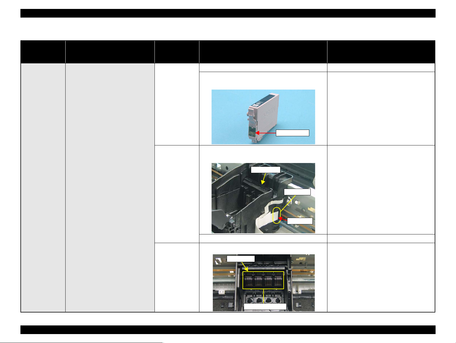
Epson Stylus NX510/SX410/SX210/NX420/NX220 series Revision B
Memory Chip
Connector
CSIC Board
Head FFC
CSIC Board
CSIC Connectors
Table 3-9. Check point for CSIC error / Incorrect Ink Cartridge according to each phenomenon
Occurrence
timing
CR position
Detailed phenomenon
Defective
unit/part name
Ink Cartridge
Check point Remedy
1. Check if Ink Cartridge is properly installed. 1. Install the Ink Cartridge properly.
2. Check if the Memory Chip is not disconnected or not
chipped.
2. Replace the Ink Cartridge with a new one.
• Power on
•Inside HP
After the printer detects that the carriage
is at the home position, an error is
displayed.
CSIC Board
CSIC Connector
1. Check if the Head FFC is connected to connector on the
CSIC Board.
2. Check if the CSIC Board is not damaged. 2. Replace the CSIC Board with a new one.
1. Check if the CSIC Connector is not damaged. 1. Replace the CSIC Board with a new one.
1. Connect the Head FFC to connector on the
CSIC Board.
TROUBLESHOOTING Error Indications and Fault Occurrence Causes 75
Confidential
Page 75
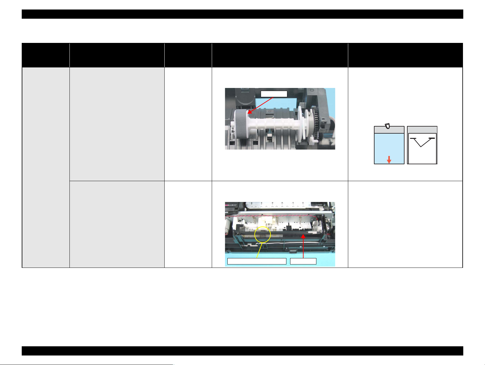
Epson Stylus NX510/SX410/SX210/NX420/NX220 series Revision B
LD Roller
Non-adhesive Area
Staples
Cloth moistened
with alcohol
CL Sheet
Adhesive Area
This side down
(Use a post card for
the base sheet)
HopperCompression Spring 3.43
Table 3-10. Check point for Paper out error according to each phenomenon
Occurrence
timing
CR position
• Operation
• –
Detailed phenomenon
The LD Roller cannot pick up paper
although the LD Roller attempt to rotate
correctly.
Defective
unit/part name
ASF Unit
Check point Remedy
1. Check if any paper dust is not adhered to the surface of
the LD Roller.
1. Check if the Hopper operates correctly in the paper
loading sequence.
1. Set a cleaning sheet in the ASF Unit up side
down. Then holding the top edge, try to load the
paper from the Printer driver. The micro pearl
on the LD Roller surface is removed. To
remove severe smear, staple a cloth moistened
with alcohol to a post card and clean the roller
in the same manner.
*If the problem is not solved, replace the ASF
unit with new one.
1. Reassemble the Compression Spring 3.43
between the Base Frame and the Hopper.
The Hopper does not operate during the
paper loading sequence although the LD
Roller rotates to load paper from the ASF
ASF Unit
Unit.
TROUBLESHOOTING Error Indications and Fault Occurrence Causes 76
Confidential
Page 76

Epson Stylus NX510/SX410/SX210/NX420/NX220 series Revision B
Extension Spring 0.143
Guide Pin
Clutch
LD Roller Shaft
Compression
Spring 2.36
Change Lever
Table 3-10. Check point for Paper out error according to each phenomenon
Occurrence
timing
CR position
Detailed phenomenon
Defective
unit/part name
Check point Remedy
1. Check if the Extension Spring 0.143 does not come off in
the Clutch mechanism.
1. Reassemble the Extension Spring 0.143 in the
Clutch mechanism.
• Operation
• –
The drive of the PF Motor is not
transmitted to the LD Roller Shaft.
ASF Unit
2. Check if the positioning hole of the Clutch does not come
off from the guide pin of the LD Roller Shaft.
3. Check if the Clutch tooth is not damaged. 3. Replace the ASF Unit with a new one.
4. Check if the Clutch is not damaged. 4. Replace the ASF Unit with a new one.
5. Check if the Compression Spring 2.36 does not come off
in the Change Lever.
2. Reassemble the positioning hole of the Clutch
on the guide pin of the LD Roller Shaft.
5. Replace the ASF Unit with a new one.
TROUBLESHOOTING Error Indications and Fault Occurrence Causes 77
Confidential
Page 77
Epson Stylus NX510/SX410/SX210/NX420/NX220 series Revision B
Table 3-10. Check point for Paper out error according to each phenomenon
Occurrence
timing
CR position
• Operation
• –
Detailed phenomenon
The LD Roller is not set to the ASF home
position and paper is always loaded from
the ASF Unit during the paper loading
sequence.
Defective
unit/part name
ASF Unit
Check point Remedy
1. Check if the tip of the Change Lever is not damaged. 1. Replace the ASF Unit with a new one.
Table 3-11. Check point for Head Cleaning error (Ink low error) according to each phenomenon
Occurrence
timing
CR position
• Operation
• –
Detailed phenomenon
Head Cleaning is not carried out. Ink Cartridge
Defective
unit/part name
Check point Remedy
1. Check if the ink remains in the Ink Cartridge. 1. Replace the Ink Cartridge with a new one.
2. Check if the Ink Cartridge can be used by installing it to
other printer.
2. Replace the Ink Cartridge with a new one.
Table 3-12. Check point for DSC Direct error according to each phenomenon (NX510/SX410 series only)
Occurrence
timing
CR position
• Operation
• –
Detailed phenomenon
The Digital Camera (as a USB device)
cannot be recognized and an error is
indicated.
Defective
unit/part name
USB Cable 1. Check if the USB Cable is damaged. 1. Replace the USB Cable with a new one.
Digital Camera
2. Confirm whether the digital camera is compatible with
the printer.
Check point Remedy
2. Replace the digital camera with a compatible
one.
Table 3-13. Check point for Memory Card error according to each phenomenon
Occurrence
timing
CR position
• Operation
• –
Detailed phenomenon
The Memory Card cannot be recognized
and an error is indicated.
Defective
unit/part name
Memory Card
Main Board Unit
Check point Remedy
1. Check if the Memory Card is compatible with the
printer.
2. Check if the Memory Card is damaged. 2. Replace the Memory Card with a new one.
3. Check if a memory card that the adaptor is needed is
inserted into the slot without using the adaptor.
1. Check if the Memory Card slot pins on the Main Board
is bent or broken.
1. Replace the Memory Card with a compatible
one.
3. Turn off the printer, then remove the card
using tweezers or a similar tool.
1. Replace the Main Board Unit with a new one.
TROUBLESHOOTING Error Indications and Fault Occurrence Causes 78
Confidential
Page 78
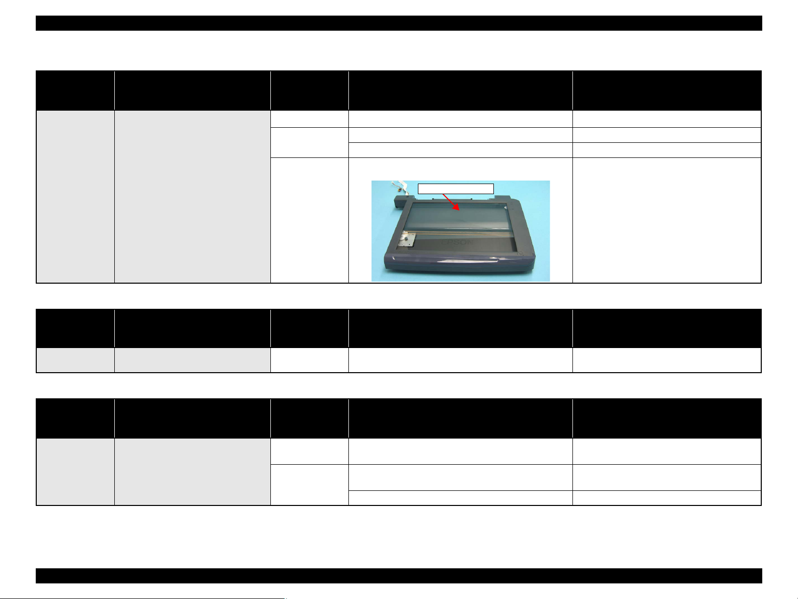
Epson Stylus NX510/SX410/SX210/NX420/NX220 series Revision B
Document Glass
Table 3-14. Check point for Index Sheet 1 error (No index Sheet) according to each phenomenon
Occurrence
timing
CR position
Detailed phenomenon
Defective
unit/part name
Document Cover 1. Check if the Document Cover is open. 1. Close the Document Cover.
Check point Remedy
1. Check if the Index Sheet is set in the wrong way. 1. Set the Index Sheet correctly.
2. Check if the Index Sheet’s standard position is clean. 2. Reprint the Index Sheet.
1. Check if the Document Glass is clean. 1. Clean the Document Glass.
• Operation
• –
Index Sheet
This error occurs when attempting to
print using the Index Sheet.
Scanner Housing
Upper
Table 3-15. Check point for Index Sheet error 2 (Image marking error) & Index Sheet error 3 (Paper marking error) according to each phenomenon
Occurrence
timing
CR position
• Operation
• –
Detailed phenomenon
This error occurs when attempting to
print using the Index Sheet.
Defective
unit/part name
Index Sheet
Check point Remedy
1. Check if the checkboxes on the Index Sheet are properly
marked out.
1. Mark it out properly.
Table 3-16. Check point for Index Sheet error 4 (Incorrect card) according to each phenomenon
Occurrence
timing
CR position
Detailed phenomenon
Defective
unit/part name
Check point Remedy
• Operation
• –
This error is generated when attempting
to print from Index Sheet.
Index Sheet
Memory Card
1. Check if the Index Sheet was printed from the inserted
Memory Card.
1. Check if the Memory Card storing the Index Sheet data is
inserted.
2. Check if the Memory Card is damaged. 2. Replace the Memory Card with a new one.
1. Change the Index Sheet to the one printed from
the inserted Memory Card.
1. Insert Memory Card storing the Index Sheet
data.
TROUBLESHOOTING Error Indications and Fault Occurrence Causes 79
Confidential
Page 79
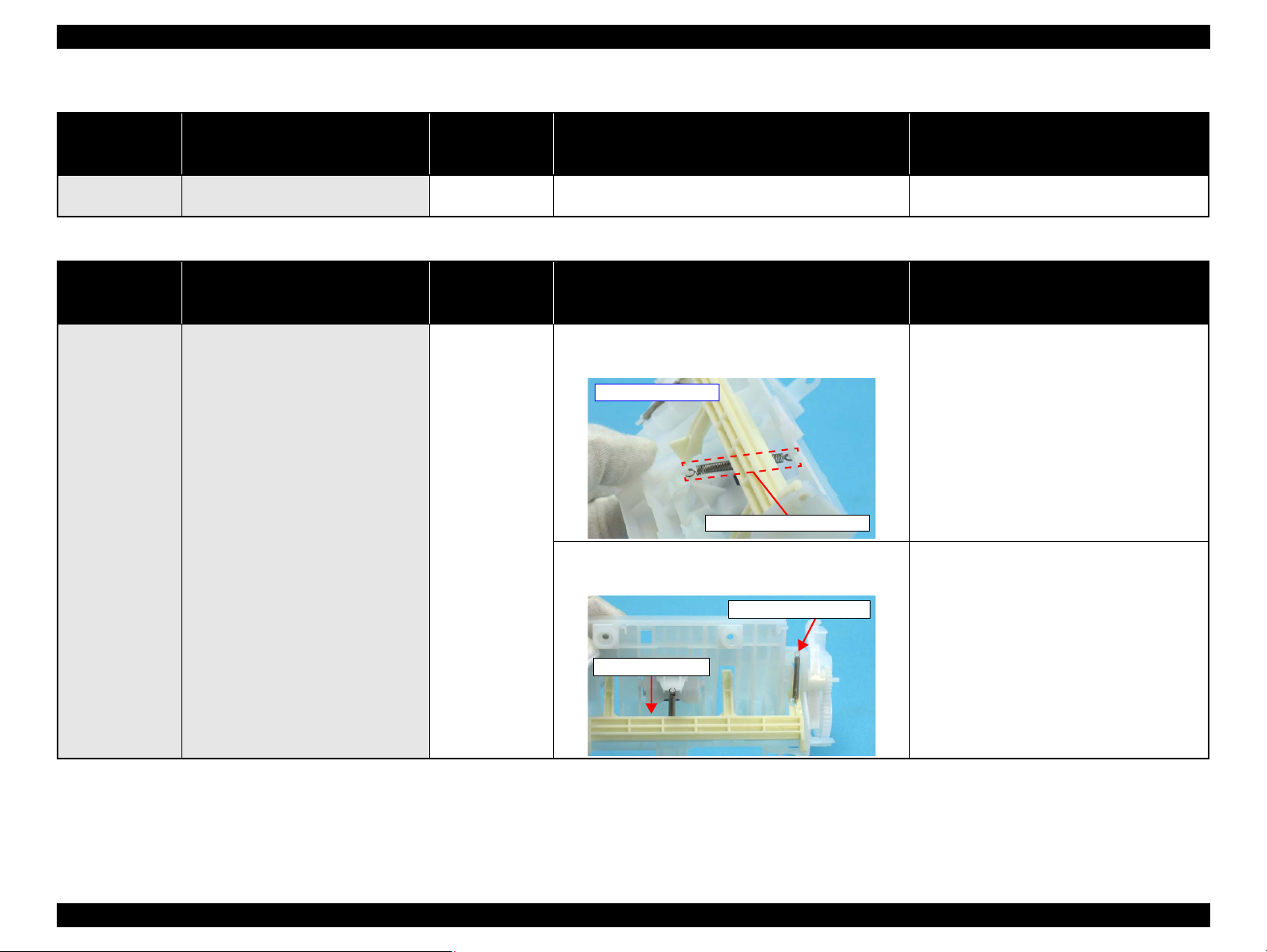
Epson Stylus NX510/SX410/SX210/NX420/NX220 series Revision B
Extension Spring Retard
Backside of ASF
Paper Back Lever
Extension Spring 0.099
Table 3-17. Check point for Pre-scanning error (photo) according to each phenomenon (NX510/SX410 series only)
Occurrence
timing
CR position
• Operation
• –
Detailed phenomenon
No photos cannot be recognized and an
error is indicated.
Defective
unit/part name
Photo
Check point Remedy
1. Check if the photo is set correctly. 1. Set the photo correctly.
Table 3-18. Check point for Double feed error according to each phenomenon
Occurrence
timing
CR position
Detailed phenomenon
Defective
unit/part name
Check point Remedy
1. Check if the Extension Spring Retard operates correctly
in the paper loading sequence.
1. Set the Extension Spring Retard between the
Retard Roller Unit and the ASF Frame.
• Operation
• –
TROUBLESHOOTING Error Indications and Fault Occurrence Causes 80
After both surfaces were printed, the
paper was ejected but an error is
displayed.
ASF Unit
2. Check if the Paper Back Lever operates correctly in the
paper loading sequence.
2. Set the Extension Spring 0.099 between the
ASF Frame and the Paper Back Lever.
Confidential
Page 80

Epson Stylus NX510/SX410/SX210/NX420/NX220 series Revision B
NX510/SX410 series
SX210 series
Panel FFC
CN1
Table 3-19. Check point for Communication error according to each phenomenon
Occurrence
timing
CR position
Detailed phenomenon
Defective
unit/part name
Check point Remedy
1. Check if the Panel FFC is connected to CN1 on the Panel
Board.
1. Connect the Panel FFC to CN1 on the Panel
Board.
• Power on
• Anywhere
When turning on the power, the printer
does not operate at all.
Panel Unit
2. Check if the Panel FFC is not damaged. 2. Replace the Panel FFC with new one.
3. Check if the Panel Board is not damaged. 3. Replace the Panel FFC with new one.
TROUBLESHOOTING Error Indications and Fault Occurrence Causes 81
Confidential
Page 81
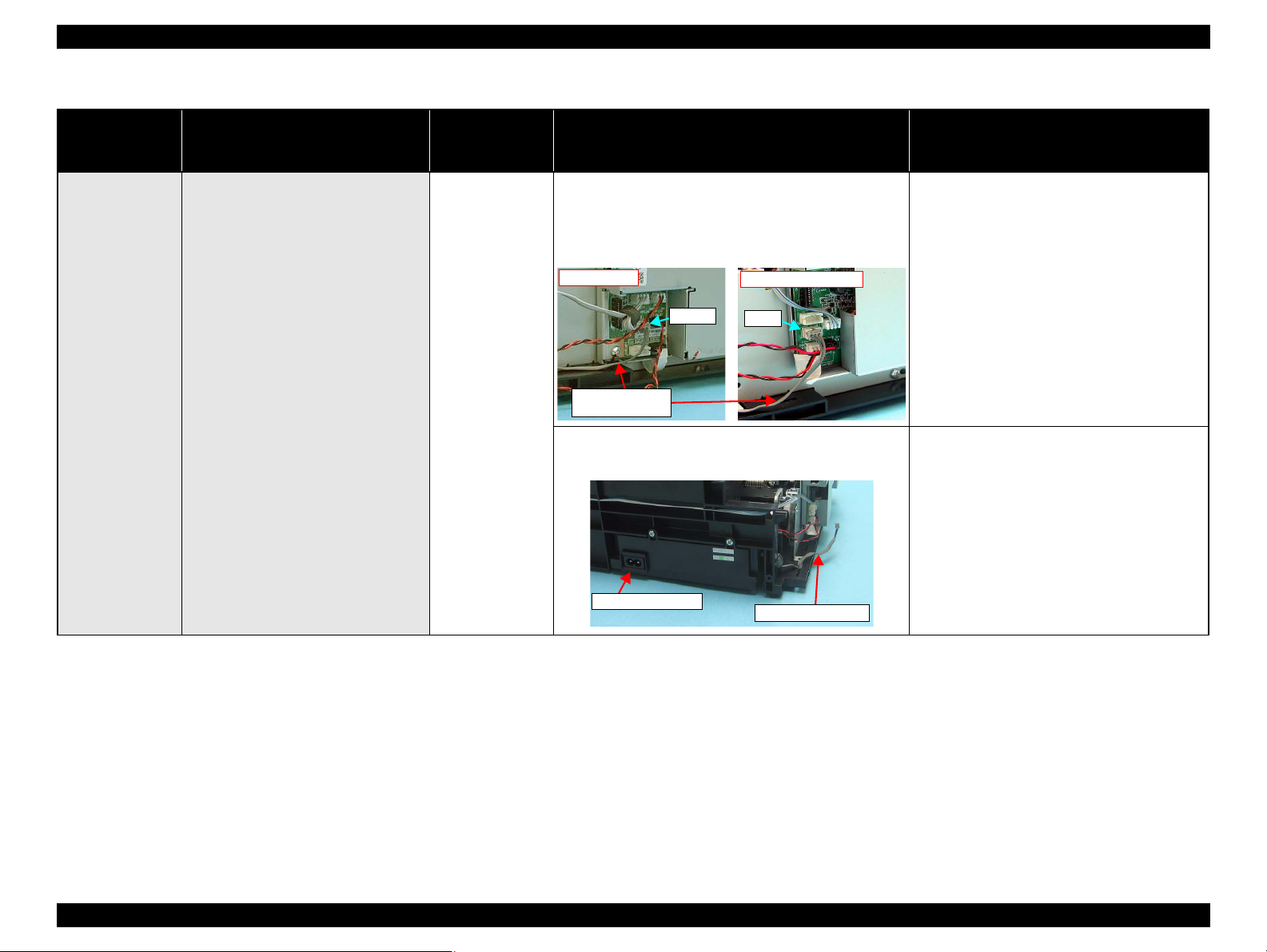
Epson Stylus NX510/SX410/SX210/NX420/NX220 series Revision B
NX510 series
CN501
PS Board
Connector Cable
SX410/SX210 series
CN1
Power Unit Cable
PS Board Unit
Table 3-19. Check point for Communication error according to each phenomenon
Occurrence
timing
CR position
Detailed phenomenon
Defective
unit/part name
Check point Remedy
1. Check if the PS Board Connector Cable is connected to
the connector on the Main Board Unit shown below.
NX510 series: CN501
SX410/SX210 series: CN1
1. Connect the PS Board Connector Cable to the
connector on the Main Board Unit shown
below.
NX510 series: CN501
SX410/SX210 series: CN1
• Power on
• Anywhere
When turning on the power, the printer
does not operate at all.
PS Board Unit
2. Check if the PS Board Connector Cable/PS Board is not
damaged.
2. Replace the PS Board Unit with new one.
* If the problem is not solved, replace the Main
Board with new one.
TROUBLESHOOTING Error Indications and Fault Occurrence Causes 82
Confidential
Page 82

Epson Stylus NX510/SX410/SX210/NX420/NX220 series Revision B
NX510 series
CN5
SX410/SX210 series
CN12, CN18
Panel FFC
Table 3-19. Check point for Communication error according to each phenomenon
Occurrence
timing
CR position
• Power on
• –
Detailed phenomenon
When turning on the power, the power on
sequence is performed correctly. But,
when any printer job is sent to the printer,
a communication error is indicated with
STM3.
Defective
unit/part name
USB Cable
Main Board Unit
Check point Remedy
1. Check if the USB Cable is connected between the printer
and the PC.
1. Check if an correct model name is stored into the address
of the EEPROM on the Main Board.
1. Check if the Panel FFC is connected to the connector on
the Main Board Unit shown below.
NX510 series: CN5
SX410 series: CN12
SX210 series: CN18
1. Connect the USB Cable to the printer and the
PC.
1. Use the Adjustment Program to write the
correct value to the EEPROM address.
1. Connect the Panel FFC to the connector on the
Main Board Unit shown below.
NX510 series: CN5
SX410 series: CN12
SX210 series: CN18
TROUBLESHOOTING Error Indications and Fault Occurrence Causes 83
Confidential
Page 83

Epson Stylus NX510/SX410/SX210/NX420/NX220 series Revision B
CN16
Cover Open Sensor cable
Table 3-20. Check point for Scanner unit open error according to each phenomenon (NX510 series only)
Occurrence
timing
CR position
Detailed phenomenon
Defective
unit/part name
Check point Remedy
1. Is the Cover Open Sensor cable properly connected to
CN16 on the Main Board?
1. Connect the Cover Open Sensor cable to CN16
on the Main Board.
• Operation
• Anywhere
The Printer Cover is closed, but the
cover open error is displayed.
Cover Open Sensor
2. Is the Cover Open Sensor cable damaged? 2. Replace the Cover Open Sensor cable with a
new one.
3. Is the Cover Open Sensor damaged? 3. Replace the Cover Open Sensor with a new
one.
TROUBLESHOOTING Error Indications and Fault Occurrence Causes 84
Confidential
Page 84

Epson Stylus NX510/SX410/SX210/NX420/NX220 series Revision B
Extension Spring Retard
Backside of ASF Unit
Paper Back Lever
Extension Spring 0.099
3.3.3 Superficial Phenomenon-Based Troubleshooting
This section explains the fault locations of the error states (print quality and abnormal noise) other than the error states (LED and STM3) in the previous section.
Table 3-21. Check point for the error that multiple sheets of paper are always loaded without LEDs and STM3
Occurrence
timing
CR position
Detailed phenomenon
Defective
unit/part name
Check point Remedy
1. Check if the Extension Spring Retard operates correctly
in the paper loading sequence.
1. Set the Extension Spring Retard between the
Retard Roller Unit and the ASF Frame.
• Operation
• –
TROUBLESHOOTING Error Indications and Fault Occurrence Causes 85
The LEDs and STM3 are not indicating
error conditions. But, multiple sheets of
paper are always loaded from the ASF
Unit.
ASF Unit
2. Check if the Paper Back Lever operates correctly in the
paper loading sequence.
2. Set the Extension Spring 0.099 between the
ASF Frame and the Paper Back Lever.
Confidential
Page 85

Epson Stylus NX510/SX410/SX210/NX420/NX220 series Revision B
Table 3-22. Check point for the abnormal noise
Occurrence
timing
CR position
• Anytime
•Anywhere
Detailed phenomenon
The abnormal noise occurs at the first
power on timing and during each
operation although the printing
operation is performed.
The Carriage Unit collides to the Upper
Paper Guide Unit during each operation.
Defective
unit/part name
Carriage Unit
ASF Unit
Upper Paper Guide
Unit
Check point Remedy
1. Check if the grease on the Carriage Path is sufficient. 1. Wipe off the remaining grease on the Carriage
path and lubricate it on its frame.
1. Check if the Change Lever moves smoothly. 1. Replace the ASF Unit with a new one.
1. Check if the Upper Paper Guide Unit is attached
securely. (check if it interferes with the Carriage Unit)
1. Reassemble the Upper Paper Guide to the
Main Frame.
Table 3-23. Check point for the defective scanned image quality
Print Quality
State
• Scanned image is
not clear.
Detailed phenomenon
There are dusts or the like on the
Document Glass. (white dots appear on
the scanned image)
There are dusts or the like on the LED
inside the Rod Lens Array. (vertical
stripes appear on the scanned image)
The LED of Scanner Carriage Unit does
not light up.
Defective
unit/part name
Upper Scanner
Housing
Scanner Carriage
Unit
Scanner Carriage
Unit
Check point Remedy
1. Check if there is any foreign material on the Document
Glass.
1. Check if there is not foreign material on the LED. 1. Remove the foreign material from the
1. Check if the LED lights up. 1. Replace the Scanner Carriage Unit with a new
1. Remove the foreign material from the
Document Glass.
(Refer to Chapter 6 “MAINTENANCE”
(p.179).)
Document Glass (blow away the dusts).
one.
TROUBLESHOOTING Error Indications and Fault Occurrence Causes 86
Confidential
Page 86

Epson Stylus NX510/SX410/SX210/NX420/NX220 series Revision B
NX510 series
SX210 series
SX410 series
Compression Spring
Seal rubber part
Table 3-24. Check point for the defective printing quality
Print Quality State Detailed phenomenon
Defective
unit/part name
Check point Remedy
1. Check if there is not any foreign material/damage around
the seal rubber part on the Cap Unit.
1. Remove the foreign material around the seal
rubber parts carefully.
• Dot missing and
mixed colors
Ink is scarcely ejected to the Cap from
the Printhead.
Ink is ejected to the Cap from the
Printhead, but the printer does not
recover from the error after cleaning or
ink change.
Ink System Unit
(Cap Unit)
2. Check if the Compression Spring is correctly mounted on
the Cap Unit.
1. Check if it returns to normal by performing CL operation
Printhead
Cleaner Blade
Main Board 1. Check if the Main Board is not damaged. 1. Replace the Main Board with a new one.
or replacing the Ink Cartridge.
2. Check if the Printhead is not damaged. 2. Replace the Printhead with a new one.
1. Check if the Cleaner Blade does not have paper dust or
bending.
2. Replace the Ink System Unit with a new one.
1. Perform CL operation and the Ink Cartridge
replacement specified times. If it doesn’t work,
change the Printhead with a new one.
1. Replace the Ink System Unit with a new one.
TROUBLESHOOTING Error Indications and Fault Occurrence Causes 87
Confidential
Page 87

Epson Stylus NX510/SX410/SX210/NX420/NX220 series Revision B
Printhead
Connector
NX510 series
CN12
CN11
CN13
Head
FFC
SX410 series
Head
FFC
CN7
CN5
CN6
SX210 series
Head
FFC
CN5
CN6
Table 3-24. Check point for the defective printing quality
Print Quality State Detailed phenomenon
Defective
unit/part name
Check point Remedy
• White streak /
abnormal discharge
Ink is ejected to the Cap from the
Printhead, but printing is not done at all
after cleaning or ink change, or
abnormal discharge occurs.
1. Check if the Head FFC is connected to the connector on
the Main Board Unit shown below.
NX510 series: CN11, CN12, CN13
SX410 series: CN5, CN6, CN7
SX210 series: CN5, CN6
1. Connect the Head FFC to the Printhead and the
Main Board Connectors.
Head FFC
2. Check if the Head FFC is not damaged. 2. Replace the Head FFC with a new one.
Printhead
1. Check if it returns to normal by performing CL operation
or replacing the Ink Cartridge.
1. Perform CL operation and the Ink Cartridge
replacement specified times. If it doesn’t work,
change the Printhead with a new one.
Main Board Unit 1. Check if the Main Board is not damaged. 1. Replace the Main Board Unit with a new one.
TROUBLESHOOTING Error Indications and Fault Occurrence Causes 88
Confidential
Page 88

Epson Stylus NX510/SX410/SX210/NX420/NX220 series Revision B
CR movement
direction
Table 3-24. Check point for the defective printing quality
Print Quality State Detailed phenomenon
Defective
unit/part name
Check point Remedy
• White streak / color
unevenness
occurrence
Vertical banding appears against the CR
movement direction. And, it looks like
uneven printing.
[Note]
If the problem is not solved, replace the
CR Motor with a new one.
Adjustment
Printhead
Main Frame
1. For printing in the Bi-D mode, check if Bi-D Adjustment
has been performed properly.
1. Check if the Nozzle Check Pattern is printed properly. 2. Perform Head Cleaning and check the Nozzle
1. Check if there is any foreign material on the Carriage
path.
2. Check if the Main Frame is deformed. 2. Replace the Main Frame with a new one.
3. Check if the grease is enough on the Carriage path of the
Main Frame.
1. Perform Bi-D Adjustment to correct print start
timing in bi-directional printing.(Refer to
Chapter 5 “ADJUSTMENT” (p.165).)
Check Pattern. (Refer to Chapter 5
“ADJUSTMENT” (p.165).)
If the problem is not solved, replace the
Printhead with a new one.
1. Remove foreign material from surface of the
Carriage path.
3. After wiping the grease G-71 on the Carriage
path with a dry, soft cloth, coat it with
grease.(Refer to Chapter 6 “MAINTENANCE”
(p.179).)
TROUBLESHOOTING Error Indications and Fault Occurrence Causes 89
Confidential
Page 89

Epson Stylus NX510/SX410/SX210/NX420/NX220 series Revision B
CR movement
direction
PF Roller Unit
Table 3-24. Check point for the defective printing quality
Print Quality State Detailed phenomenon
Defective
unit/part name
Check point Remedy
• White streak / color
unevenness
occurrence
Micro banding appears horizontally
against the CR movement direction and
it appears with the same width.
[Note]
If the problem is not solved, replace the
PF Motor with a new one.
The Star wheel mark against the CR
movement direction.
Printer driver &
exclusive paper
Printhead
PF Roller Unit
1. Check if the suitable paper is used according to the printer
driver setting.
1. Check if the Nozzle Check Pattern is printed correctly. 1. Perform the Head Cleaning and check the
1. Check if there is not any foreign material on the surface
of the PF Roller Unit.
2. Check if the PF Roller Unit is not damaged. 2. Replace the PF Roller Unit with a new one.
1. Check if the Star Wheel Holder does not come off. 1. Reassemble the Star Wheel Holder correctly.
2. Check if the surface of the Star Wheel Holder Assy is flat. 2. Replace the Star Wheel Holder Assy with a new
1. Use the suitable paper according to the printer
driver setting.
Nozzle Check Pattern. (Refer to Chapter 5
“ADJUSTMENT” (p.165).)
If the problem is not solved, replace the
Printhead with a new one.
1. Clean the surface of the PF Roller Unit
carefully with the soft cloth.
one.
Star Wheel Holder
Assy
Printing is blurred.
Printer driver &
exclusive paper
Printhead
1. Check if the suitable paper is used according to the printer
driver setting.
1. Check if the correct Head ID is stored into the EEPROM
by using the Adjustment Program.
1. Use the suitable paper according to the printer
driver setting.
1. Input 16-digit code of the Head ID into the
EEPROM by using the Adjustment Program.
TROUBLESHOOTING Error Indications and Fault Occurrence Causes 90
Confidential
Page 90
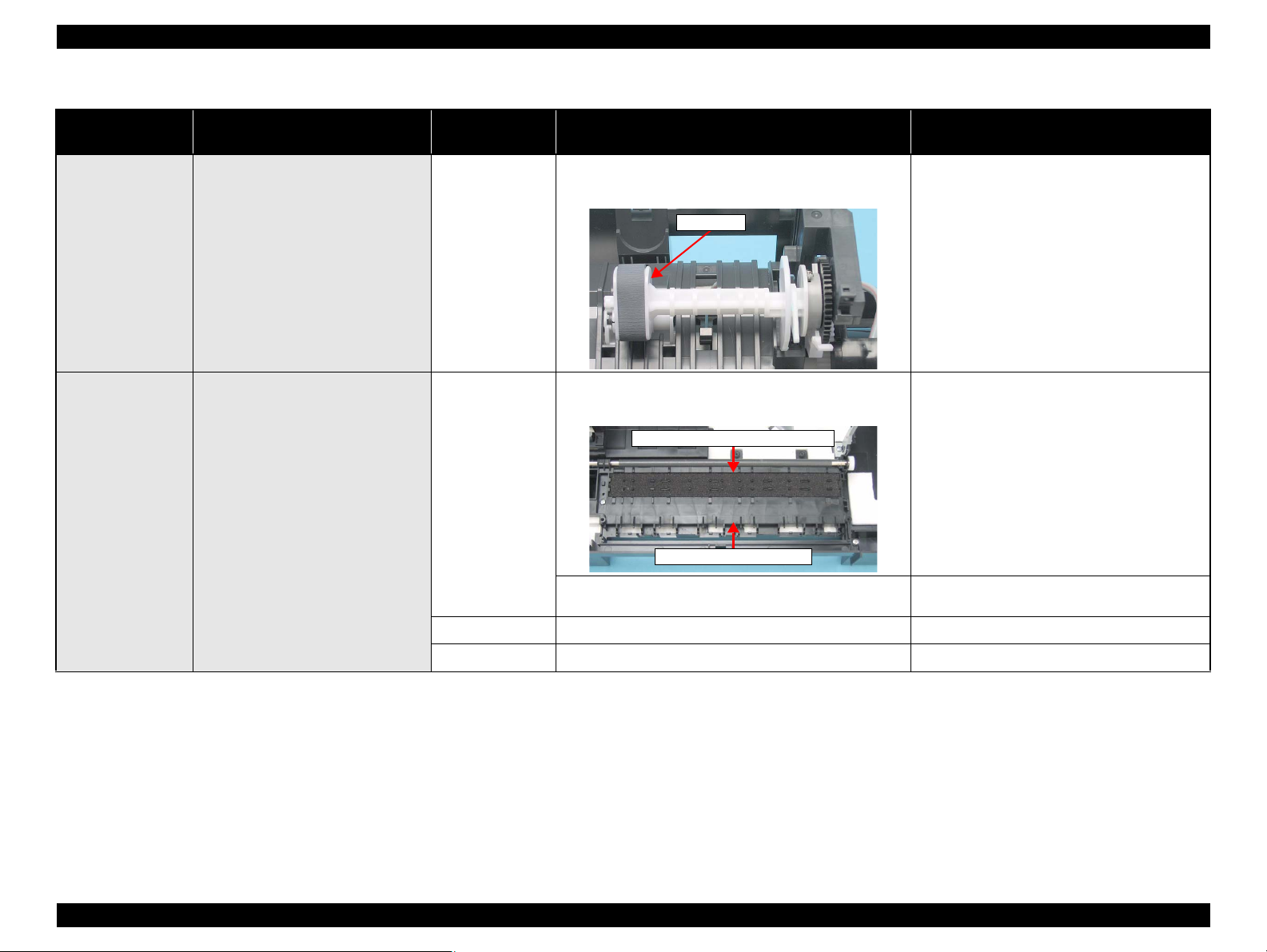
Epson Stylus NX510/SX410/SX210/NX420/NX220 series Revision B
LD Roller
Front Paper Guide Unit
Porous Pad Front Paper Guide
Table 3-24. Check point for the defective printing quality
Print Quality State Detailed phenomenon
Defective
unit/part name
Check point Remedy
• Print start position
slip
• Ink stain of paper
The printing operation is correctly
performed. But, the top margin is
insufficient than usual one.
Ink stain occurs at the back, top end or
bottom end of the print paper.
1. Check if any paper dust is not adhered to the surface of
the LD Roller.
ASF Unit
1. Check if the Front Paper Guide Unit is free from ink
stain.
Front Paper Guide
2. Check if heaps of ink are not formed on Porous Pad Front
Paper Guide.
EJ Roller Unit 1. Check if the EJ Roller Unit is free from ink stain. 1. Clean the EJ Roller Unit with a soft cloth.
PF Roller Unit 1. Check if the PF Roller Unit is free from ink stain. 1. Clean the PF Roller Unit with a soft cloth.
1. Set a cleaning sheet in the ASF up side down.
Then holding the top edge, try to load the paper
from the Printer driver. The micro pearl on the
LD Roller surface is removed. To remove
severe smear, staple a cloth moistened with
alcohol to a post card and clean the roller in the
same manner. As for the cleaning sheet, refer to
“ Check point for Paper out error according to
each phenomenon ” (p.76).
* If the problem is not solved, replace the ASF
Unit with a new one.
1. Clean the Front Paper Guide Unit with a soft
cloth.
2. Replace the Front Paper Guide Assy with a new
one.
TROUBLESHOOTING Error Indications and Fault Occurrence Causes 91
Confidential
Page 91
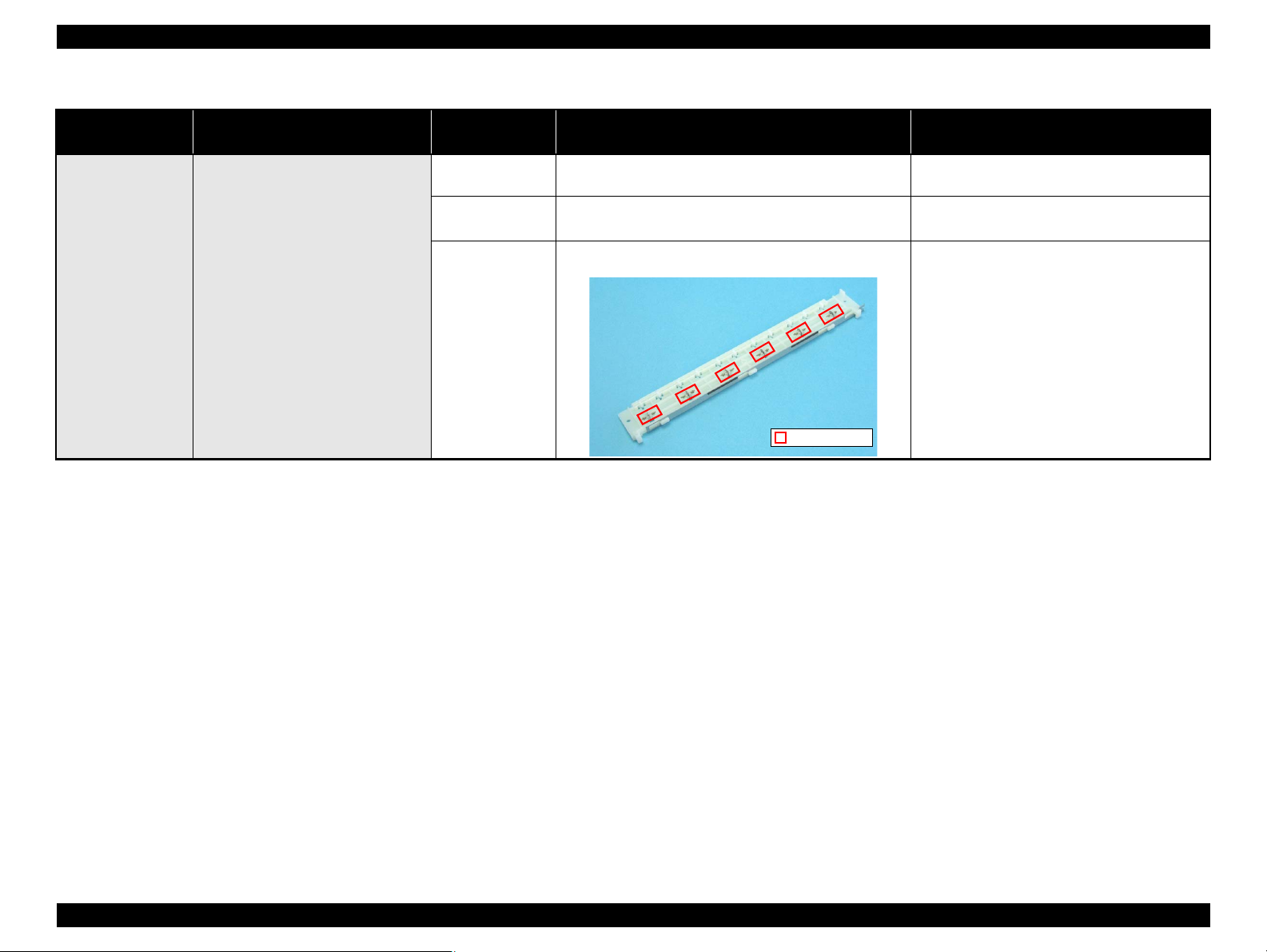
Epson Stylus NX510/SX410/SX210/NX420/NX220 series Revision B
Star Wheels
Table 3-24. Check point for the defective printing quality
Print Quality State Detailed phenomenon
Defective
unit/part name
Check point Remedy
• Ink stain of paper
Ink sticks to other than the print area of
the paper, resulting in contamination.
Printhead
Upper Paper Guide
Unit
Star Wheel Holder
Assy
1. Check if the Printhead Cover does not have the ink drop. 1. Clean the Printhead Cover carefully with a soft
cloth.
1. Check if the Upper Paper Guide Unit is free from ink
stain.
1. Check if the Star Wheels is free from ink stain. 1. Clean the Star Wheels with a soft cloth.
1. Clean the Upper Paper Guide Unit with a soft
cloth.
TROUBLESHOOTING Error Indications and Fault Occurrence Causes 92
Confidential
Page 92

Epson Stylus NX510/SX410/SX210/NX420/NX220 series Revision B
3.4 Network Troubleshooting (NX510/NX420 series only)
This section describes troubleshooting for the network function of NX510/NX420
series. For troubleshooting of NX420 series; however, skip the description on the wired
LAN because NX420 series supports the Wireless LAN only.
Troubles in Network Settings
Table 3-25. Troubles in Network Settings
Symptom Check Point Remedy
Connection with
Access Point/
Detection of Access
Point can not be made
(Wireless LAN)
Communication with
wired LAN can not be
made
1. Check if Access Point is ready
for the connection.
2. Check if Access Point is too far
from the printer or blocked by
obstruction.
3. Check if Access Point has any
limitation for the access.
4. Check if Access Point setting is
made for non-display of the
SSID (Network).
5. Check if WEP key or setting for
the password is correct.
1. Check if the Wireless LAN
Setting on the Control Panel is
“Disable”.
2. Check if the combination for the
HUB and router etc. and Link
Speed of the Printer is proper.
3. Check if 10Base-T Repeater
HUB is used.
Check if the connection can be
made from the other devices.
Move Access Point closer to
the printer or clear off the
obstruction.
Check Access Point and
change the setting for the
access by setting the MAC
Address or IP Address, etc. of
the printer.
Input the SSID from the
Control Panel.
Check the WEP key and the
password in a case-sensitive
manner.
Change the Wireless LAN
Setting into
because Wireless LAN and
Wired LAN can not be used at
the same time.
Correct the Link Speed setting
properly.
Try other HUBs (Switching
HUB etc.).
“Disable”
,
Troubles in installing a software
Table 3-26. Troubles in Installing a Software
Symptom Check Point Remedy
“Can not connect to
internet thru LAN” is
displayed.
1. In Wireless LAN’s case, check if
the network connection between
the PC and Access Point is made.
2. In Wired LAN’s case, check if
the computer and the printer are
properly connected to a LAN
port such as a hub or a router.
3. Check the status of network
settings/connection by printing
the network status sheet.
4. Check if the link lamp on the
Access Point or hub connected to
the printer is lighting or flashing.
5. Check is IP address is correctly
set.
6. For the setting of the Windows
Firewall or commercially
available security software,
check if the installed network
access is set to “Shut down” or
“Block” etc.
Correctly connect the
computer and the Access
Point.
Correctly connect the
computer and the printer to a
LAN port such as a hub or
router using a LAN cable.
Correctly set the network
connection again if the
network connection is not
made.
• Try using another port.
• Replace the LAN cable.
• Configure Wireless LAN
setting correctly.
Correctly set IP address.
Set the Windows Firewall or
commercially available
software as the exceptional
application.
*If the problem is not solved
when using the commercially
available security software,
restart it once.
TROUBLESHOOTING Network Troubleshooting (NX510/NX420 series only) 93
Confidential
Page 93

Epson Stylus NX510/SX410/SX210/NX420/NX220 series Revision B
Troubles during printing and scanning from PC
Table 3-27. Troubles during printing and scanning from PC
Symptom Check Point Remedy
Print cannot be made
Scan cannot be made
EPSON Scan cannot
be started
1. In Wireless LAN’s case, check if
the network connection between
the PC and Access Point is made.
2. In Wired LAN’s case, check if
the computer and the printer are
properly connected to a LAN
port such as a hub or router.
3. Check the status of network
settings/connection by printing
the network status sheet.
4. Check if the link lamp on the
Access Point or hub connected to
the printer is lighting or flashing.
5. Check if the network settings are
correctly configured?
6. Check if the network setting
screen is displayed on the
Control Panel.
1. For EPSON Scan settings, check
if IP address is set directly.
Correctly connect the
computer and the Access
Point.
Correctly connect the
computer and the printer to a
LAN port such as a hub or
router using a LAN cable.
Correctly set the network
connection again if the
network connection is not
made.
• Try using another port.
• Replace the LAN cable.
• Configure Wireless LAN
setting correctly.
Correctly configure the
network settings.
Close the screen.
If IP address is set using the
DHCP function, specify IP
address by searching address.
TROUBLESHOOTING Network Troubleshooting (NX510/NX420 series only) 94
Confidential
Page 94

DISASSEMBLY/ASSEMBLY
CHAPTER
4
Confidential
Page 95
Epson Stylus NX510/SX410/SX210/NX420/NX220 series Revision B
Notation Product name
NX510 series Epson Stylus NX510/NX515/SX510W/SX515W/TX550W
SX410 series Epson Stylus NX415/SX410/SX415/TX410/TX419
SX210 series
Epson Stylus NX215/SX210/SX215/TX210/TX213/
TX219/ME OFFICE 510
NX420 series
Epson Stylus NX420/TX420W/SX420W/SX425W/Epson
ME OFFICE 560W
NX220 series
Epson Stylus TX220/NX220/SX218/TX228/Epson ME
OFFICE 520
4.1 Overview
C H E C K
P O I N T
In this chapter, the product names are called as follows:
4.1.1 Precautions
See the precautions given under the heading “WARNING” and “CAUTION” in the
following columns when disassembling or assembling this product.
W A R N I N G
Disconnect the power cable before disassembling or
assembling the printer.
If you need to work on the printer with power applied, strictly
follow the instructions in this manual.
Always wear gloves for disassembly and reassembly to protect
your eyes from ink. If any ink gets in your eyes, wash your
eyes with clean water and consult a doctor immediately.
Always wear gloves for disassembly and reassembly to avoid
injury from sharp metal edges.
To protect sensitive microprocessors and circuitry, use static
Description of the disassembly/reassembly procedures in this
chapter is for NX510/SX410/SX210 series. Description of
NX420/NX220 series is in Chapter 8 Epson Stylus NX420/
NX220 series (p.188). Therefore, when confirming the
procedures for NX420/ NX220 series, refer to " 8.4
DISASSEMBLY/ASSEMBLY" (p.194).
This chapter describes procedures for disassembling the main components of this
product. Unless otherwise specified, disassembled units or components can be
C A U T I O N
reassembled by reversing the disassembly procedure. Procedures which, if not strictly
observed, could result in personal injury are described under the heading
“WARNING”. “CAUTION” signals a precaution which, if ignored, could result in
damage to equipment. Important tips for procedures are described under the heading
“CHECK POINT”. If the assembly procedure is different from the reversed
disassembly procedure, the correct procedure is described under the heading
“REASSEMBLY”. Any adjustments required after reassembly of components or parts
are described under the heading “ADJUSTMENT REQUIRED”. When you have to
remove any components or parts that are not described in this chapter, refer to the
exploded diagrams in the appendix.
Read the following precautions before disassembling and assembling.
DISASSEMBLY/ASSEMBLY Overview 96
discharge equipment, such as anti-static wrist straps, when
accessing internal components.
Never touch the ink or wasted ink with bare hands. If ink
comes into contact with your skin, wash it off with soap and
water immediately. If you have a skin irritation, consult a
doctor immediately.
When transporting the printer after installing the ink cartridge,
pack the printer for transportation without removing the ink
cartridge and be sure to secure the Ink Cartridge to the printer
cover with tape tightly to keep it from moving.
Use only recommended tools for disassembling, assembling or
adjusting the printer.
Observe the specified torque when tightening screws.
Apply lubricants as specified.
(See Chapter 6 MAINTENANCE (p.179) for details.)
Make the specified adjustments when you disassemble the
printer. (See Chapter 5 ADJUSTMENT (p.165) for details.)
when reassembling the Waste Ink Tube, make sure that the tip
of waste ink tube is placed in the correct position, otherwise
ink may leak.
When using compressed air products; such as air duster, for
cleaning during repair and maintenance, the use of such
products containing flammable gas is prohibited.
Confidential
Page 96

Epson Stylus NX510/SX410/SX210/NX420/NX220 series Revision B
4.1.2 Tools
Use only specified tools to avoid damaging the printer.
Table 4-1. Tools
Name EPSON Tool Code*
(+) Phillips screwdriver #1 1080530
(+) Phillips screwdriver #2 ---
Flathead screwdriver ---
Flathead Precision screwdriver #1 ---
Tweezers ---
Longnose pliers ---
Acetate tape 1003963
Nippers ---
Note * : All of the tools listed above are commercially available.
EPSON provides the tools listed with EPSON tool code.
4.1.3 Work Completion Check
If any service is made to the printer, use the checklist shown below to confirm all
works are completed properly and the printer is ready to be returned to the user.
Table 4-2. Work Completion Check
Classification Item Check Point Status
Self-test Is the operation normal? OK / NG
ON-line Test Is the printing successful? OK / NG
Printhead (Nozzle
check pattern print)
Carriage Mechanism
Printer Unit
Is ink discharged normally from
all the nozzles?
Does it move smoothly? OK / NG
Is there any abnormal noise
during its operation?
Is the CR Motor at the correct
temperature? (Not too hot to
touch?)
Is paper advanced smoothly? OK / NG
No paper jamming? OK / NG
No paper skew? OK / NG
OK / NG
OK / NG
OK / NG
Paper Feeding
Mechanism
No multiple feeding? OK / NG
No abnormal noise? OK / NG
Is the paper path free of any
obstructions?
Is the PF Motor at correct
temperature?
OK / NG
OK / NG
DISASSEMBLY/ASSEMBLY Overview 97
Confidential
Page 97

Epson Stylus NX510/SX410/SX210/NX420/NX220 series Revision B
Table 4-2. Work Completion Check
Classification Item Check Point Status
Is glass surface dirty? OK / NG
Mechanism
Is any foreign substance mixed
in the CR movement area?
Does CR operate smoothly? OK / NG
OK / NG
Scanner unit
ON-line Test ON-line Test Is the operation normal? OK / NG
Copy Copy Is the local copy action normal? OK / NG
Adjustment
Lubrication
Function ROM Version Version: OK / NG
Packing
CR mechanism
LED
Specified
Adjustment
Specified
Lubrication
Ink Cartridge
Waste Ink pad
Does CR operate together with
scanner unit?
Does CR make abnormal noise
during its operation?
Does LED turn on normally?
And is white reflection test done
near home position?
Are all the adjustment done
correctly
Are all the lubrication made at
the specified points?
Is the amount of lubrication
correct?
Are the ink cartridges installed
correctly?
Are the waste ink pads adequate
to absorb?
OK / NG
OK / NG
OK / NG
OK / NG
OK / NG
OK / NG
OK / NG
OK / NG
Is the printer carriage placed at
the capping position?
Have all the relevant items been
included in the package?
OK / NG
OK / NG
Others
Protective materials
Attachments,
Accessories
DISASSEMBLY/ASSEMBLY Overview 98
Confidential
Page 98

Epson Stylus NX510/SX410/SX210/NX420/NX220 series Revision B
4.1.4 Procedural Differences between the Models
Description of the disassembly/reassembly procedures in this chapter is based on NX510 series. Those procedures for some parts/components vary in models. Check the following
for the differences and references.
Differences of NX510/SX410/SX210 series: See Table 4-3.
Differences of NX420/NX220 series: See Table 8-4 in 8.4.1 "Procedural Differences between the Models (p194) ".
Table 4-3. Differences between Models
Item Difference NX510 series SX410 series SX210 series Reference*
NX510 series
“ 4.4.2 Panel Unit/LCD Unit ” (p112)
SX410 series
“ 4.7.2 Panel Unit/LCD Unit (SX410 series) ” (p152)
SX210 series
“ 4.8.2 Panel Unit/LCD Unit (SX210 series) ” (p159)
NX510 series
“ 4.5.1 Printhead ” (p117)
SX410 series
“ 4.7.3 Printhead (SX410 series) ” (p154)
SX210 series
“ 4.8.3 Printhead (SX210/NX220 series) ” (p162)
Panel Unit
Printhead
Disassembly/reassembly
procedures
(The shape of the Panel Units
differs.)
Disassembly/reassembly
procedures
(The Printheads differ.)
NX510 series
Disassembly/reassembly
Main Board Unit
Cover Open
Sensor
Wireless LAN
Board
Scanner Carriage
FFC
Left Frame Existence of Ferrite core Yes No No
procedures
(The shape and the connector
locations differ.)
Existence of Cover Open
Sensor
Existence of Wireless LAN
Board
Existence of Ferrite core No Yes No
Yes No No
Yes No No
“ 4.4.1 Main Board Unit ” (p109)
SX410 series
“ 4.7.1 Main Board Unit (SX410 series) ” (p150)
SX210 series
“ 4.8.1 Main Board Unit (SX210/NX220 series) ” (p158)
“ 4.5.4 Removing the Printer Mechanism (Lower Housing) ”
(p122)
“ 4.4.1 Main Board Unit ” (p109)
“ 4.3.4 Scanner Unit/Hinge ” (p104)
“ 4.5.5 Left Frame ” (p123)
DISASSEMBLY/ASSEMBLY Overview 99
Confidential
Page 99

Epson Stylus NX510/SX410/SX210/NX420/NX220 series Revision B
Table 4-3. Differences between Models
Item Difference NX510 series SX410 series SX210 series Reference*
Existence of Ferrite core Yes No No
Front Frame
Right Frame
PF Encoder
Sensor
Ink System Unit
PF Roller Attachment location of the Grounding Spring that is in contact with the PF Roller
PF Motor Length of the PF Motor cable
Printer
Mechanism
USB Cover The shape of the USB Cover differs.
Scanner Unit Connector Numbers on the Main Board Unit for the Scanner Carriage FFC and the Scanner Motor cable
Power Supply
Unit
Cartridge Position
Label
Waste Ink Pads Quantity and the shape of Waste Ink Pads
Number of pieces of acetate
tape that secure the Head FFC
One piece Two pieces Two pieces
to the Front Frame
Existence of Porous Pad
Frame Right
Yes Yes No
Existence of Acetate Tape Yes No Yes
Number of the Waste Ink
Tubes
Two tubes One tube One tube
Disassembly/reassembly procedures differ due to the difference in the following items:
• Routing of cables around the Main Board Unit
• Number of screws
• Existence of Cover Open Sensor
Connector Number on the Main Board Unit for the Power Unit Cable
The attachment standard and the type of the Cartridge Position Label
“ 4.5.6 Front Frame/Right Frame ” (p124)
“ 4.5.9 PF Encoder Sensor ” (p128)
“ 4.5.17 Ink System Unit ” (p138)
“ 4.5.19 PF Roller ” (p142)
“ 4.5.11 PF Motor ” (p129)
“ 4.5.11 PF Motor ” (p129)
NX510 series
“ 4.5.4 Removing the Printer Mechanism (Lower
Housing) ” (p122)
SX410 series
“ 4.7.4 Removing the Printer Mechanism (Lower Housing)
(SX410 series) ” (p156)
SX210 series
“ 4.8.4 Removing the Printer Mechanism (Lower Housing)
(SX210/NX420/NX220 series) ” (p164)
“ 4.3.4 Scanner Unit/Hinge ” (p104)
“ 4.4.3 Power Supply Unit ” (p115)
“ 4.3.5 Upper Housing/Card Slot Cover ” (p107)
“ 4.5.20 Waste Ink Pads ” (p143)
Note * : When indicating one reference, the instructions for each model are described in the procedure.
DISASSEMBLY/ASSEMBLY Overview 100
Confidential
Page 100
Epson Stylus NX510/SX410/SX210/NX420/NX220 series Revision B
Start
You need to remove the parts/units shown in
dashed line box if they exist on the way to the
target part/unit.
Colored blocks are the sections where
disassembling/reassembling procedures differ
between models.
Unless otherwise specified, this chapter
describes the disassembling/reassembling
procedures based on NX510 series.
This flowchart is for NX510/SX410/SX210
series. See " 8.4.2 Disassembly Procedures"
(p.195) for NX420/NX220 series.
“ 4.4.2 Panel Unit/LCD Unit ” (p112)
“ 4.3.1 Paper Support Assy ” (p102)
“ 4.6.2 Scanner Carriage Unit ” (p146)
“ 4.6.1 Upper/Front Scanner Housing ” (p145)
“ 4.5.15 Upper Paper Guide ” (p136)
“ 4.3.4 Scanner Unit/Hinge ” (p104)
“ 4.4.2 Panel Unit/LCD Unit ” (p112)
“ 4.4.1 Main Board Unit ” (p109)
“ 4.5.6 Front Frame/Right Frame ” (p124)
“ 4.5.3 Hopper ” (p121)
“ 4.5.13 Main Frame Assy ” (p132)
“ 4.5.9 PF Encoder Sensor ” (p128)
“ 4.5.19 PF Roller ” (p142)
“ 4.3.5 Upper Housing/Card Slot Cover ” (p107)
“ 4.5.2 CR Scale ” (p120)
“ 4.3.2 Stacker Assy ” (p102)
“ 4.3.3 Document Cover/ASF Cover ” (p103)
“ 4.5.16 ASF Unit ” (p136)
“ 4.5.18 Front Paper Guide ” (p141)
“ 4.5.4 Removing the Printer Mechanism
(Lower Housing) ” (p122)
“ 4.5.9 PF Encoder Sensor ” (p128)
“ 4.5.2 CR Scale ” (p120)
“ 4.5.3 Hopper ” (p121)
“ 4.5.17 Ink System Unit ” (p138)
“ 4.5.12 CR Motor ” (p131)
“ 4.5.5 Left Frame ” (p123)
“ 4.5.7 Star Wheel Holder Assy ” (p126)
“ 4.5.7 Star Wheel Holder Assy ” (p126)
“ 4.5.8 EJ Roller ” (p127)
“ 4.5.11 PF Motor ” (p129)
“ 4.5.7 Star Wheel Holder Assy ” (p126)
“ 4.5.10 PF Scale ” (p129)“ 4.5.8 EJ Roller ” (p127)
“ 4.5.14 CR Unit ” (p135)
“ 4.5.10 PF Scale ” (p129)
“ 4.6.3 Scanner Motor Unit ” (p149)
“ 4.5.10 PF Scale ” (p129)
“ 4.4.3 Power Supply Unit ” (p115)
“ 4.5.1 Printhead ” (p117)
“ 4.5.20 Waste Ink Pads ” (p143)
4.2 Disassembly Procedures
For disassembling each unit, refer to the pages in the following flowchart.
C H E C K
P O I N T
DISASSEMBLY/ASSEMBLY Disassembly Procedures 101
Figure 4-1. Disassembling Flowchart
Confidential
 Loading...