

Page 1
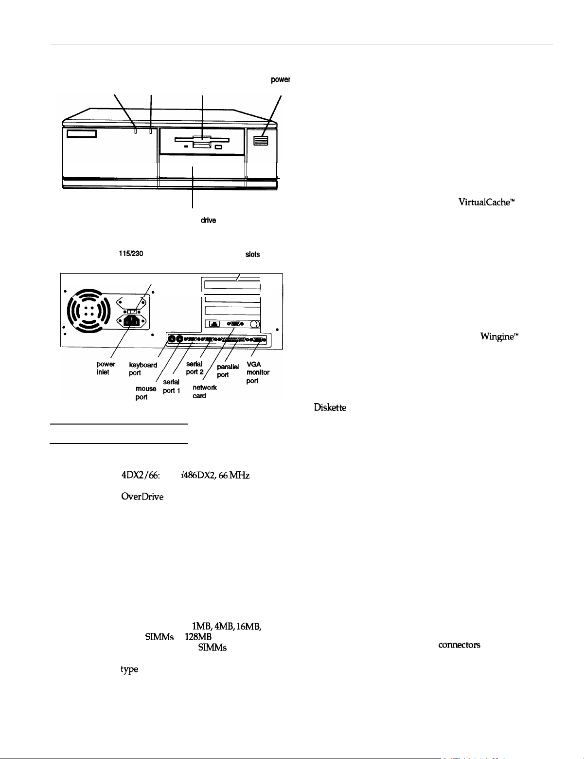
EPSON NX
power (SPEED)
light
hard disk
access
light
bay for hard disk, diskette, tape,
CD-ROM, or other drive
115mo
VAC switch
.
Computer Specifications
CPU and Memory
32-bit CPU
System speed
Memory
4DX2/66:
Intel
i486DX2,66 MHz
microprocessor; supports future Intel
OverDrive
processors
High, low, and automatic speeds
available; high speed is CPU-dependent
(66 MHz), low speed is simulated 8 MHz,
automatic speed switches from high to
low only for diskette drive access; speed
selection through SETUP, keyboard
command, or ESPEED program; 0 wait
state memory access at high speed
20MB standard (4MB DRAM soldered on
main system board and one 16MB SIMM);
expandable using lMB,
64MB
SlMMs
to
128MB
main system board; SlMMs must be 70 ns,
36-bit, 72-pin, gold-leaded, fast-page mode
we
diskette
drive
option card
rt
I-
4MB, 16MB,
maximum on
power
button
ROM
Video RAM
Shadow RAM
128KB ROM containing system BIOS and
video BIOS; 64KB ROM containing SETUP
code
2MB video RAM on main system board
Automatic shadowing of system and VGA
BIOS ROM into RAM; shadow RAM
address control selectable through SETUP
Cache
8KB of internal cache (built into the
microprocessor); cache testing and address
control selectable through SETUP
VirtualCache
Epson proprietary
VirtualCache’”
feature
automatically creates a “virtual cache”
buffer the size of maximum system
memory
slots
/
/
1
Math
coprocessor
Clock/calendar
Built into the microprocessor
Real-time clock, calendar, and CMOS
RAM on main system board; separate
battery backup
Controllers
Video
Chips and Technologies
Wingine’”
P64200 VGA controller on main
system board; provides resolutions
of up to 1024 x 768 x 64K colors or
1120 x 832 x 64K colors, depending on
the available drivers
DiSk&te
Controller on main system board supports
up to two diskette drives or one diskette
drive and one tape drive (DOS only)
Hard disk
Interface on main system board supports
up to two IDE hard disk drives with
built-in controllers
Interfaces
Monitor
VGA interface built into main system
board for analog or multifrequency VGA
monitor; 15-pin, D-shell connector
Parallel
One standard 8-bit parallel, bidirectional
interface built into main system board;
port assignment and I/O address
selectable through SETUP; 25-pin, D-shell
connector
Serial
Two RS-232C, programmable,
asynchronous interfaces built into main
or
system board; port assignment and I/O
addresses selectable through SETUP;
9-pin, D-shell
co~ectors
6/30/93
EPSON NX-1
Page 2
EPSON NX
Keyboard
Mouse
Option slots
Speaker
Feature
connector
LAN adapter
Mass Storage
Horizontal
mounts
Vertical
mount
Diskette drives
Hard disk
drives
ES/2
compatible keyboard interface built
into main system board; keyboard speed,
delay, and num lock settings selectable
through SETUP; 6-pin, mini DIN connector
I’S/2
compatible mouse interface built
into
main
system board; 6-pin, mini DIN
connector
Four standard
X-bit
(or
&bit)
I/O
expansion slots (three available); ISA
compatible; 8 MHz bus speed
Internal; operation controllable through
SETUP and volume selectable by software
IBM compatible VGA pass-through
interface built into main system board;
26-pin connector
Intel
EtherExpress 16C, &bit ISA-
compatible Ethernet adapter; supports
BNC coax (thin Ethernet), AUI
(thick Ethernet), and RJ-45
DE15s
(10BaseT
Ethernet); Link and Activity status LEDs;
software configurable for I/O address,
IRQ, connector type, and I/O- or memory-
mapped buffering; diagnostic utility
included
Three drives maximum (two horizontal
mounts and one vertical mount),
configurable using the following:
Up to two externally-accessible,
half-height horizontal mounts; each
horizontal bay can accommodate one
5%inch
form factor hard disk, diskette,
tape, CD-ROM, or other drive, or one
3%-inch form factor hard disk, diskette,
tape, CD-ROM, or other drive with
51/4-inch
mounting frames attached
One internal third- or half-height vertical
mount; vertical bay can accommodate one
3%-inch form factor hard disk or other
drive
3.5~inch,
5.25~inch, 1.2MB
3*4-inch
1
or
&MB
(high-density)
(highdensity), DOS only
5&inch
form factor hard disk
drive(s), up to half-height size; the first
mounted vertically, second mounted
horizontally; (the vertical bay can
accommodate only
3l/i-inch
form factor
drives; the horizontal bays can
accommodate
3*4-&h
or
5!@nch
form
factor drives)
Other devices
Half-height tape drive, CD-ROM drive, or
other storage device;
or
31&inch
form factor with
51/4-inch
form factor
5’!-inch
mounting frames attached
Keyboard
Detachable; two-position height;
101 sculpted keys; numeric/cursor control
keypad; four-key cursor control keypad;
12 function keys
Power Supply
Type
Input ranges
145 Watt, fan-cooled
90
to
132 VAC and 180 to 264 VAC, switch
selectable voltage
Maximum
outputs
+5
VDC at
18 Amps,
+12
VDC at 4.0
Amps, -5 VDC at 0.3 Amps, -12 VDC at
0.3 Amps
Frequency
Cables
47to63Hz
Two to main system board; four to mass
storage devices
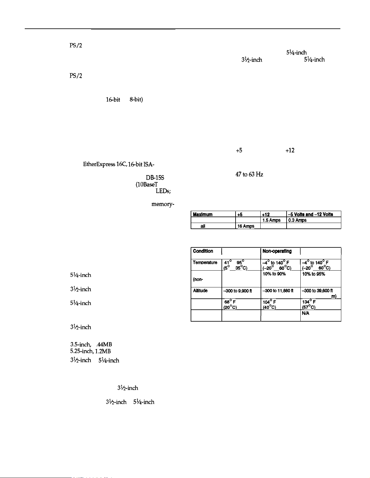
Option Slot Power Limits
Maxlmum
For each slot
For ail four slots 16Amps3 Amps
current
+5
volts
7 Amps
+12
volts
1.5Amps 0.3Amps
-SVoRsand-12Volts
0.3
Amps
Environmental Requirements
Condltlon
Temtxvature
Humidity
(non-
condensing)
Atlituds
Maximum
wet bulb (20°C)
Acoustical
noise
1
Operatlng range1 Nonqeratlng1 Storage range
I
I
41’
to
95’
(SO
to
35OC)
20% to 60%
~toQ,QOOR
(-100 to 3,000 m) (-100 to 3,600 m) (-100 to 12,000
66’F
37.4 dB(A)
1
range
F
I-4°t01400F
(do0
to
6oOC)
1O%toQO%
4ooto 11,660R
104’F 134’F
(4OOC)
WA N/A
I I I
I
14’to140°F
(-2o”
lO%to95%
4300t039,600ft
(57OC)
to
6oOC)
Physical Characteristics
Width
14.8 inches (370 mm)
Depth 16.5 inches (412 mm)
Height
4.8 inches (120
mm)
Weight 16.7 lb (7.6 kg), without keyboard
1
m)
EPSON NX-2
6/30/93
Page 3
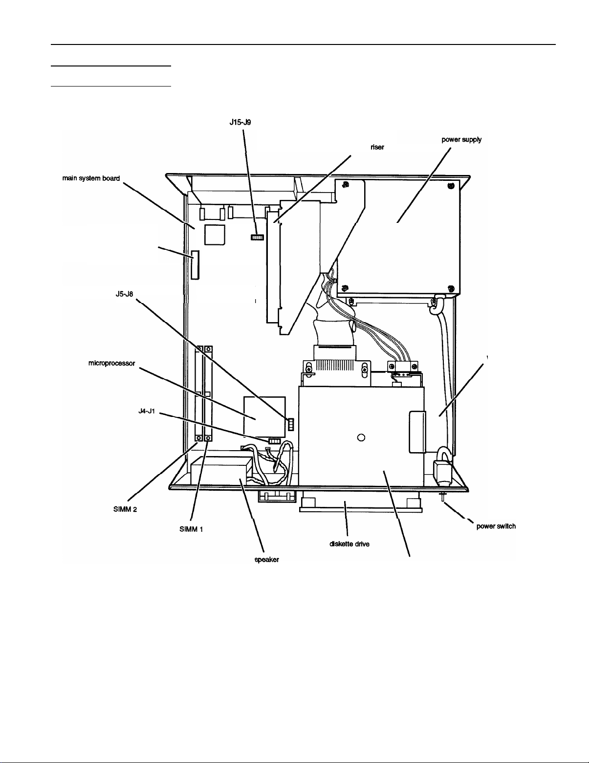
Major Subassemblies
EPSON NX
J1549
VGA feature connector
J5J6
0
q
q
L
option board
riser
card
vertii drive bay
6/30/93
horizontal drive bays
EPSON NX-3
Page 4
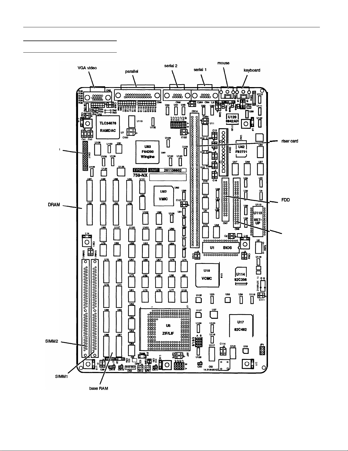
EPSON NX
Main System Board Diagram
alternate
VGA
feature
connector
-
risercad
option board
connector
video
DFtAM
- FDD
connector
1
HDD
connector
EPSON NX-4
6/30/93
Page 5
EPSON NX
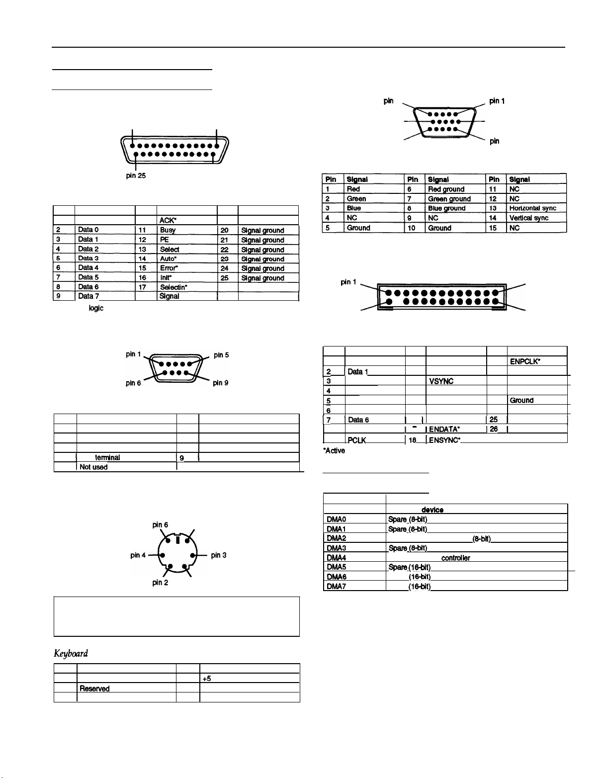
Connector Pin Assignments
Parallel Port Connector (CN5)
pin 13
t-1
pi;25
Parallel Port Connector Pin Assignments
Pin Signal
strobe
1
19 IData
*Active low
kgic
Pin Signal
10
ACK’
I
16I
Signal
ground
Serial Port Connectors (CN4 and CN8)
Serial Port Connector Pin Assignments
Pin Slgnai
1
Data carrier detect
2
Receive data
3
Transmit data
1
Data temjnai ready
4
5 INotused
IQ1 Ring indicator
I
pin 1
I
pin 14
Pin Slgnai
6
Data set ready
7
Request to send
6
Clear to send
I
Pin Signal
19
Signal
ground
VGA Port Connector (CN2)
Pin
5
pin 10
pin 15
VGA Port Connector Pin Assignments
VGA Feature Connector (CN17)
pin 1
I
pin2
VGA Feature Connector
Pin Signal
1
Data0
12
IData
Data2
Dat
Data4
Data5
17 IData
6
Data7
9
PCLK
*A&e
low logic
a3
l
eeoeaeoeae
Pin Assignments
Pin Signal
10
11
12
13
14
15
I
16 ] Ground
- -..-.-_
1
17
I16
BLANK
HSYNC 20
VSYNC
Ground
Ground
Ground
1
ENDATA’
1
ENSYNC*
pin 1
pin6
ptn
11
pin 25
pin 26
Pin Slgnai
19
ENPCLlC
Not connected
21
Ground
22
Ground
23
GtWnCt
24
Ground
I251 Not connected
I
I261Not
connected
I
Keyboard Connector (CN10) and Mouse Connector (CN9)
pin6
F%
““‘w pin3
pin2
pin 5
I
pin 1
Caution
Although the keyboard and mouse connectors are
physically identical, they cannot be used interchangeably.
Keybcuzrd
Pin Signal
2
3
and Mouse Connector Pin Assignments
1
Data
ReSeWed 5
Ground
Pin
4
6
Signal
+5
VDC (fused)
clock
Reserved
6/30/93
DMA Assignments
Level
DMAO
DhAAl span3 @-bit)
DMA2
DMA3
DMA4
DMA5 span3 (M-bit)
DMA6
DMA7
Assigned device
spate p-bit)
Floppy disk dttve controller (&bit)
spam p-bit)
Cascade to DMA controller 1
spare (Mbit)
spare (w-bit)
EPSON NX-5
Page 6

EPSON NX
Hardware Interrupts
System l/O Address Map
Hex address’ Aeelgned device
000-OlF
020 - 021
022 - 024 Epson reserved function
040-043
080-081,084
070 - 071 (CMOS)
080-08F
OAO-OAl
OCO - ODF
OF0
OF1
OF8 - OFF
1 lFO-
lF8
200-207
278 - 27A
1280 -
2DF
2El
2E2
and
I2F8 - 2FF
2E3
300-31F
348-357
380-383
384-387
p-368
38C-38F
378 - 37A
380-38F
390-393
3A0 - 3AF
3BO-3BA
3BC-3BE
3C0 - 3CF
3D0 - 3DF
3F0 -
3F7
3F8 -
3FF
8E2
and
8E3
790-793
AE2 and AE3
B90-893
EE2 - EE3
1390 - 1393
DMA controller
Interrupt controller 1,8259A, master
1
Timer, 8254-2
I8042
(Keyboard and mouse)
1
Real-time clock
j
DMA page register,
1
Interrupt controller 2,8259A
DMA controller 2,8237A-5
Clear math coprocessor busy
j
Reset math coprocessor
1
Math coprocessor
1
Hard disk drive
IGameWO
1
Parallel printer port 3
1
Alternate enhanced graphics adapter
[ GPIB
(adapter 0)
I
Data aafukition (adapter 0)
ISelialport2
LAN adapter
DCA 3278
PC network (low address)
Resewed
1
PC network (high address)
1
Resewed
I
Parallel printer port 2
SDLC, bisync 2
Cluster
I
Bisynchronous 1
I
Monochrome display and printer adapter
Parallel printer port 1
Enhanced graphics adapter
Color/graphics monitor adapter
Floppy disk drfve controller
Serialport
Data acquisttiin (adapter 1)
Cluster (adapter
Data acquisttiin (adapter 2)
Cluster (adapter 2)
J
Data acquisition (adapter 3)
1
Cluster (adapter 3)
1,8237A-5
NMI
(non-ma&able interrupt mask)
74LS812
1)
Hex address*
22El
FO80 -
F085
F089 -
FO8D
*
Recommended addresses for installing devices
1 Asslgned device
j GPIB
(adapter 1)
Epson reserved function
Epson resewed function
Jumper Settings
See the illustration on page 3 for the location of the jumpers
on the main system board.
CPU Speed Jumper Settings*
CPU speed
DW88
l
Factory settings
Jl
A
J2
A
53
B A
CPU Type Jumper Settings’
CPU type J5
ODP488DX88
l
This table shows the factory settings for jumpers
these settings only if you install a future CverDrfve processor.
Other ]umper Settings
I
JlO
I
Jll
l
Factory setting
“To use a mouse connected to a port on an option card, set J9 to B and J12 to
A. lf you connect another type of pointing device (such as a joy stick) to the
option card port, set both jumpers to A.
IA‘B
I
A*
A A
Function
Enables the built-in mouse connector
Dtsables the built-in mouse connector
Enables the built-in VGA display adapter
Disables the built-in VGA dlsptay adapter
A color monitor is Installed
A monochrome monitor is installed
Enables a mouse or other polnting device
connected to an opt&n card
Disables a mouse or other pointing device
connected to an option card
Disables the password
Enables the password
Reserved
J6
57
B
J5-J8.
You need to change
J4
J6
B
EPSON NX-6
6/30/93
Page 7
EPSON NX
Processor Chips
Support is provided for a future OverDrive processor.
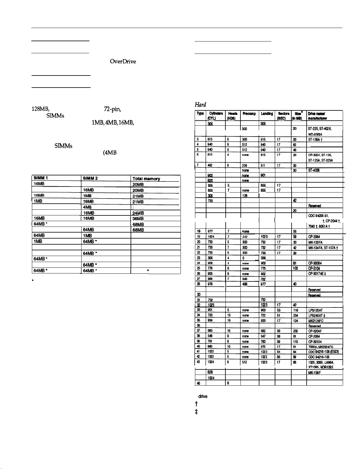
SIMM lnstallation
There are two SIMM sockets on the main system board. To
increase the amount of memory in the computer up to
128MB,
you can install 36-bit,
mode SIMMs that operate at an access speed of 70 ns or
faster, with a capacity of lMB,
The following table shows the possible SIMM configurations;
do not install memory in any other configuration. Make sure
that both
SWIMS
operate at the same speed. The computer
comes with 20MB of memory @MB soldered on the main
system board and one 16MB SIMM).
SIMM Configurations
1MB
18MB
4MB
16MB
I64MB’
64MB
l
1MB
84MB
l
4MB
64MB -
16MB
64MB -
*
When SIMM is available
This memory configuration diiles the 4MB of soldered memory.
I4MI
j16MB
j16MB
I
64MB
1MB
64MB *
4MB
64MB =
18MB
64MB *
164~~’
n-pin,
4MB, 16MB,
l
gold-leaded, fast-page
or 64MB.
24MB
1 241
MB
I38MB
Ii
68MB
68MB
89MB
69MB
72MB
72MB
84MB
84MB
1
128MB
.
*
Hard Disk Drive Types
The table below lists types of hard disk drives you can use in
the computer. Check this table and your hard disk manual to
find the correct type number(s) for the hard disk drive(s)
installed in the computer. You need to enter the type
number(s) when you set the hard disk drive configuration in
the SETUP program.
Had
Disk Drive Types
Type cylnders kds Recomp IAndIng &ctars
no.
(CYL)
1
306 4
2 615
(HDS)
4
126
300
zone
3[)6
615 17
I I I
6
733
9
QW
10 820
11
16%
12
I655
13
x6
14
723
15
16 612 4
17 977
I I
II\ Inn
29
30
3l
73?
32
I@3
5
none
15
none
3
nom
I5
Inane
17
na-e
6
120
7
none
0
5 300 977 17
I I
17
"-
5
1466
7 300
5
none
733 17 30
Qol
620 17 20
16%
1655 117
1
319 17 20
1733
663 17
1
1 I
977
tm,
,
,I
1336
I!YYl
,
#Y
IQ77
732 17 42
Ice'
sb*
(SEC) (hM8) mmnuhdumr
17
17
117
17
17 56
47
1s
17
46
33
46
17
17
"
10
20
112
135
' '
49
4
a
40
!!a
IO
81
loo
162
40
40
P
orlw-
ST-225,ST-W6,
ST-m6
I
CDC942S51,
I CP-3044
t,CP-2044t,
7060t,6051At
cR7lMa
w-30084
CP3104
CP-3ol74Es
I
1
1
---
942l6-106ESDn I
IXTIUE
44
45
46
828
la?4
615
I
10
none
5 512 la?3 17
8
126
626
616 17
34
137
42
40
M&;
NDR1065
* Actual size when formatted may be slightly different than the size listed on the
drive
label.
t
Hard disk drive supported in translate mode
$
Epson drives
6/30/93
EPSON NX-7
-
I
Page 8

EPSON NX
If the computer has an Epson 170MB or 240MB hard disk
drive, select the appropriate type number from the table
below.
Epson Hard Disk Drive Types
Type4
number Epson hard disk drive
28
34
17OMB
24OMB
lnstallation/Support Tips
Cl
If you are using a copy-protected program that does not
require a key disk but requires a special procedure to
install it on a hard disk, set the speed to low while you
install the program. Then set the speed to high while you
load and run the program. If this does not work, try
installing and loading the program at low speed and then
change to high speed to run it.
Ci
You can change the processor speed using the SETUP
program, the ESPEED program, or keyboard commands.
See the User’s Guide
and
Setup Guide
for more information.
Power
The computer has an input voltage selection switch on the
back panel to select between 115 VAC, for USA and
Canadian use, and 230 VAC, for use in other countries.
Mouse and Keyboard
When connecting the mouse and keyboard to the computer,
be careful to plug them into the proper ports. Although the
ports are physically identical, they are not interchangeable,
and you may damage the main system board if you plug the
connectors into the wrong ports.
Installing Diskette Drives
Make sure that the drive type has been correctly selected in
the SETUP program.
Installing Hard Disk Drives (for DOS Use)
It is recommended that a 16-bit, AT-type hard disk
controller be used if you are installing a drive that cannot
use the embedded IDE interface. If you install a non-IDE
hard disk drive and controller card, you need to use the
SETUP program to disable the built-in IDE hard disk
drive interface.
See the hard disk drive type tables on pages 7 and 8 and
use the SETUP program to enter the correct type
number(s) for the hard disk drive(s) installed in the
computer. (Also be sure to use the SETUP program to set
the hard disk drive configuration if you install or remove
a hard disk drive.) You can select a type number that
matches the parameters for the drive or a type number
with parameters having lesser values, as long as they do
not exceed the maximum capacity (in MB) of the drive. If
there is no match for the drive, you can press Enter and
then F2 at the Hard disk 1 or 2 option and enter the
drive’s exact parameters.
Password
Make sure that you do not forget the password you set. If
you do, you must disable it by setting jumper J13 on the main
system board to position A.
Information Reference List
Engineering Change Notices
None.
Technical Information Bulletins
None.
Product Support Bulletins
None.
Related Documentation
TM-EESNNX
PL-EPSNNX
SI’KEI’SNNX EPSON NX Self Paced Kit
400227900
400227800
400193100
EPSONNXServiceManual
EPSON NX Parts Price List
EPSON NX Setup Guide
EPSON NX User’s Guide
EPSON VGA Utilities Guide for Wingine
based products
Software Problems
Cl
If you are using a copy-protected program that can run
only on a diskette or that requires a key disk, try to load
the program at high speed. If you can’t load the program
at high speed, set the processor speed to automatic.
EPSON NX-8
6/30/93
 Loading...