

Page 1
®
EPSON
EQUITY™LT™-286e
System Diagnostics
User’s Guide
Page 2

IMPORTANT NOTICE
DISCLAIMER OF WARRANTY
Epson America makes no representations or warranties, either express or implied, by
or with respect to anything in this manual, and shall not be liable for any implied
warranties of merchantability and fitness for a particular purpose or for any indirect,
special, or consequential damages. Some states do not allow the exclusion of
incidental or consequential damages, so this exclusion may not apply to you.
COPYRIGHT NOTICE
All rights reserved. No part of this publication may be reproduced, stored in a
retrieval system, or transmitted, in any form or by any means, electronic, mechanical,
photocopying, recording, or otherwise, without the prior written permission of Epson
America, Inc. No patent liability is assumed with respect to the use of information
contained herein. While every precaution has been taken in the preparation of this
publication, Epson America assumes no responsibility for errors or omissions. Nor is
any liability assumed for damages resulting from the use of the information contained
herein. Further, this publication and features described herein are subject to change
without notice.
Epson is a registered trademark of Seiko Epson Corporation.
TRADEMARKS
Equity and LT are trademarks of Epson America, Inc.
MS-DOS is a registered trademark of Microsoft Corporation.
Copyright 0 1989 by Epson America, Inc.
Torrance, California
Y19499100200
ii
Page 3

Contents
Introduction..
Starting the Diagnostics Program.
Creating a Database
The DIAG Main Menu Screen
Selecting Diagnostics Tests
Setting the Run Time Parameters
Timebound Testing
Continuous Testing
Passbound Testing
Error Logging..
Executing Diagnostics Tests in Batch Mode
Running the Tests.
System Board Diagnostics
Basic Functionality Test
CPU Protected Mode Test.
Processor Speed Test
Coprocessor Test
DMA Controller Test
Interrupt Controller Test.
Timer Test
RTC Test
CMOS Validity Test
Memory Diagnostics
BIOS ROM Test
Parity Test
Pattern Test
Walking 1’s Test.
Walking 0’s Test.
Address Test
Refresh Test
.........................................
..........................
.....................................
............................
...............................
..........................
.................................
.................................
..................................
....................................
..................
......................................
.................................
.............................
...........................
................................
...................................
...............................
............................
........................................
.........................................
................................
.....................................
...................................
........................................
.......................................
...................................
...................................
.......................................
.......................................
1
2
2
4
6
7
9
9
9
10
12
12
13
13
13
14
14
14
15
15
16
16
17
18
18
18
19
19
19
20
iii
Page 4

Hard Disk Diagnostics
Hard Disk Parameters.
Disk drive identifier.
Disk drive type
Interleave factor
Bad track list
Start and end cylinder numbers
Start and end head numbers
Hard Disk Format.
Auto Interleave
Media Analysis.
Performance Test
Seek Test
Read/Verify Test
Check Test Cylinder
Force Bad Tracks
Hard Disk Error Messages
Floppy Disk Diagnostics
Diskette Format
Drive Speed Test
Random R/W Test
Sequential R/W Test
Disk Change Line Test
Floppy Disk Error Messages
Keyboard Diagnostics
Controller Test.
Scan/ASCII Code Test
Keyboard Clock Line Test
Keyboard Data Line Test.
.........................................
...................................
....................................
....................................
...................................
...................................
...................................
....................................
...................................
....................................
....................................
...............................
............................
.................................
...............................
..................................
...................
......................
..................................
................................
............................
..................................
..................................
................................
..............................
...........................
..............................
............................
............................
20
21
21
22
22
23
23
24
24
25
26
27
28
28
29
29
30
31
32
32
32
33
33
33
34
35
35
35
35
iv
Page 5

Video Diagnostics
Adapter Test
Attribute Test
80x25 Display Test.
40x25 Display Test.
320x200 Graphics Test
640x200 Graphics Test
Page Selection Test
Color Test
640x350 Graphics Test
Video Error Message.
Miscellaneous Diagnostics
Printer Adapter Test
.......................................
......................................
.....................................
.................................
.................................
..............................
..............................
.................................
.........................................
..............................
................................
................................
................................
Communication Adapter Test.
Keyboard Scan/ASCII Codes
..............................
........................
36
36
36
36
37
37
37
37
37
38
38
38
38
39
41
V
Page 6

Introduction
This booklet describes how to use the diagnostics program,
called DIAG, to test the condition of your computer’s main unit
and peripheral devices, The DIAG program provides tests to
check the following hardware:
CI
System board
Cl
Memory
Ll
Hard disk drive
0
Diskette drive
LI
Keyboard
CI
Video adapter board and monitor
CI
Printer and communications ports
After you start the diagnostics program, you can create a
database that records the location of faulty memory chips, if any
exist. This database displays a graphic representing your
computer’s memory board and identifies the faulty chips.
Once you select a test, you need to specify how long to run it.
You use the Run Time Parameters window to specify a certain
length of time to run the test, run it continuously until you
interrupt it, or specify a number of times to run the test.
System Diagnostics 1
Page 7

Starting the Diagnostics Program
To start the diagnostics program, follow these steps:
1.
Insert the Diagnostics diskette in drive A.
2.
Turn on or reset the computer.
3.
At the MS-DOS@ prompt, type the following and press
Enter:
DIAG
The Diagnostics program displays a title screen.
4.
Press any key to continue.
Creating a Database
You can create a database to record the location of faulty
memory chips that are causing memory errors. To graphically
represent the memory board on the screen, you need to identify
your system’s memory configuration.
In the lower portion of the screen, you see this message:
Press <Esc> to bypass database creation
Press ESC if you do not want to create the database. The DIAG
main menu appears so you can select the tests you want to run.
2 System Diagnostics
Page 8

If you want to create a database, follow these steps:
1.
Type the name (from 1 to 50 characters) that identifies your
company or the computer and press Enter in response to
this prompt:
vendor's name :
(maximum 50 characters)
For example, type
2.
Type the computer’s model number (from 1 to 8 characters)
and press Enter in response to this prompt:
model number
EPSON
and press
.
.
Enter.
(maximum 8 characters)
For example, type
DIAG stores this information in a file called DIAGS.CNF.
3.
If a database with this vendor name and model number does
not exist, you see this message:
LT-286e
and press
Enter.
Database does not exist - press
any key except <Esc> to continue
To create the database, press any key other than ESC.
Now you respond to the screen prompts to update the
configuration. You can accept the default values that DIAG
presents by pressing Enter. When you see the diagram of
the motherboard, press ESC to continue the diagnostics.
If a database with the specified vendor name and model
number exists, you see this message:
Your database already exists -
want to update (Y/N)? N
System Diagnostics
3
Page 9
To update the existing database, press Y and Enter. Now
you respond to the screen prompts to update the
configuration.
If you do not want to update the database, press N and
Enter. You see the DIAG main menu.
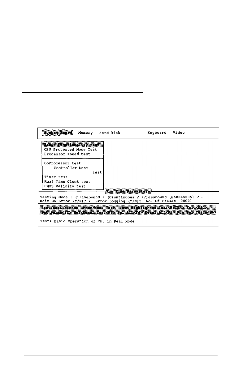
The DIAG Main Menu Screen
The DIAG main menu screen looks like this:
~~~~~~~~~~ Memoly
:.:-A. . . .
..I. _.... . . . .
.
Processor speed test
DMA
Controller test
Interrupt Controller test
Timer test
Real Time Clock test
Hard Disk
Keyboard Video
Miscl.
The program’s title, copyright information, and the date and
time appear at the top of the screen.
The DIAG options line shows these categories of tests: System
Board, Memory, Hard Disk, Floppy, Keyboard, Video, and
Miscellaneous.
After you select a category, DIAG provides a submenu of the
available diagnostics tests. When the main menu first displays,
you see the submenu of diagnostics tests for the System Board
category.
4 System Diagnostics
Page 10
The Run Time Parameters window lets you specify how long
you want the test to run, whether you want DIAG to notify you
of each error as it occurs, and whether to create a log of all
errors that occur during testing.
The Help window shows the keys you use to make menu
selections.
A short message describing each test you highlight displays at
the bottom of the screen.
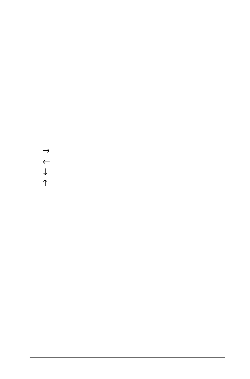
You use these keys to make menu selections and run diagnostics
tests:
Key
+
t
1 Move to the next test
t
Enter
F2
F3
F4
F5
F6
Function
Move to the next window (or device)
Move to the previous window (or device)
Move to the previous test
Start the test
Set the Run Time Parameters
Select or deselect a test
Select all tests
Deselect all tests
Run all
selected tests
system Diagnostics 5
Page 11

Selecting Diagnostics Tests
This section describes the various ways you can select the tests
you want to run.
To start a single test, move the cursor to highlight the test
category on the main menu. Then move the cursor to the
submenu and highlight the test you want to perform. Press
Enter to start the test.
To select several tests at one time, move the cursor to each test
you want to perform and press F3. If you decide you do not
want to run a selected test, highlight the test name and press F3
again.
You can press F4 to select all tests for all devices, and press F5
to deselect all selected tests.
Once you select a test, it remains selected until you deselect it.
If you run a test or a group of tests and start testing again, DIAG
performs the same tests unless you deselect them.
You must enter certain parameters for the hard disk drive and
the diskette drive tests. If you use F3 to select these tests, DIAG
prompts you for the information. If you use F4 to select these
tests, DIAG prompts you for the information during the first
pass of the test. If you perform more than one pass of the test,
DIAG uses the same parameters for each pass.
6
Systems Diagnostics
Page 12

You cannot include certain tests in a group. The tests that must
run separately include:
category
System
Hard Disk
Board
Floppy
Keyboard
Miscellaneous
After you select the test(s) you want to run, you must set the
Run Time Parameters.
Test
Timer test
Real Time Clock test
Hard Disk Format
Auto Interleave
Media Analysis
Force Bad Tracks
Disk Change Line Test
Scan/ASCII Code Test
Printer Adapter Test:
Comm. Adapter Test
Setting the Run Time Parameters
To specify the Run Time Parameters, press F2 to move to the
Run Time Parameters window. DIAG displays default values for
each of the run time parameters.
You can press ESC at any time to exit the Run Time Parameters
window and return to the submenu of diagnostics tests.
The first: run time parameter defines how long or how many
times to run the test. You see this prompt:
Testing Mode: (T)imebound / (C)ontinuous /
(P)assbound [max = 65535] (T/C/P) ? P
System Diagnostics 7
Page 13

Type T and press Enter to run the selected tests in Timebound
mode. In Timebound mode, DIAG runs the tests for the
amount of time you specify.
Type C and press Enter to run the selected tests in Continuous
mode. In Continuous mode, the tests run until you interrupt
them.
Type P and press Enter to run the diagnostics tests in
Passbound mode. In Passbound mode, DIAG executes the
selected tests the number of times you specify. This is the
default setting.
The next prompt is:
Wait on error (Y/N) ? Y
Press Y and Enter if you want DIAG to pause when an error
occurs during a test. DIAG pauses and waits for you to press
Enter before continuing. This lets you view the error message
and make notes about the error. This is the default setting.
Press N and Enter if you want DIAG to continue when an error
occurs.
The next prompt is:
Error logging (Y/N) ? N
Press Y and Enter to record the errors that may occur during
the test. See the “Error Logging” subsection for details.
Press N and Enter if you do not want to create the log. This is
the default setting.
If you decide not to wait on errors, you should select error
logging so you can review the errors that occur during the tests.
Next, DIAG requests information it needs to perform the type
of testing you selected.
8 System Diagnostics
Page 14

Timebound Testing
If you selected Timebound testing, you see this prompt:
Period :001 hr 00 min
Specify the amount of time you want to run the selected
Type the number of hours, from 000 to 999, and press Enter.
Then type the number of minutes, from 00 to 59, and press
Enter. You can use the backspace key
(t)
to edit your input.
Continuous Testing
If you selected Continuous testing, DIAG needs no additional
information. After you specify whether to create the error log,
DIAG returns to the main menu. You see this message in the
Run Time Parameters window:
Test Mode:
Passbound Testing
If you selected Passbound testing, you see this prompt:
of Passes : 00001
No.
Specify the number of times (from 1 to 65535) you want DIAG
to run the test(s). Or press Enter without entering a number to
select the default of one pass. You can use the backspace key to
edit your input.
Continuous
test(s).
Running a test multiple times provides reliability testing of
essential functions only. In most cases, running a test once is
sufficient.
System Diagnostics 9
Page 15

If you specify a number larger than 65535, DIAG subtracts
65535 from your entry to determine how many times to run the
test. For example, if you enter a value of 65540, DIAG runs the
test(s) five times.
Error Logging
When you request error logging, DIAG displays the following
pop-up window:
Log errors on disk
Log errors to printer (LPT1)
Log errors to serial port (COM1)
Cancel error logging
Highlight the device you want to use to store or print the error
messages. Press Enter to select the device, or press ESC to exit
the pop-up window and return to the Error logging prompt.
If you select
another pop-up window:
Log errors on disk,
DIAG displays
Floppy disk A:
Floppy disk B:
Hard disk C:
Highlight the disk where you want to store the error messages.
Press Enter to select the specified disk drive.
DIAG creates a file called ERROR.LOG in the current
directory of the specified disk drive. After running the tests, you
can open the ERROR.LOG file to review the errors that
occurred during the tests.
10
System Diagnostics
Page 16

After selecting error logging, DIAG uses this device (and/or
disk drive) for error logging until you indicate you do not want
error logging. You can then specify a new device and/or disk
drive by selecting error logging in the Run Time Parameters
window. When you specify a new device and/or disk drive,
DIAG erases the existing ERROR.LOG file.
If you select the printer, DIAG writes the error messages to the
device connected to your parallel port assigned LPT1. If you
select the serial port, DIAG writes the error messages to the
device connected to your serial port assigned COM1.
If you select Cancel error logging, DIAG changes
the error logging response from Y to N.
When you specify the device for error logging, one of the error
messages may appear:
Floppy disk A not present
Floppy disk B not present
Hard disk C not present
Printer port not present
Serial port not present
Error
Error
in
printer status
in
serial port status
Error in floppy drive A
Record the error message and select a different device for error
logging.
System Diagnostics
11
Page 17

Executing Diagnostics Tests in Batch Mode
To execute the selected group of diagnostics tests in batch
mode, simply press F6.
DIAG highlights each test name as it runs the test.
If you selected Passbound testing, DIAG displays the pass
number on the right side of the screen above the Run Time
Parameters window. For example:
Pass :
When DIAG is executing a group of tests, you can stop the
testing and return to the System Board submenu of tests by
pressing Ctrl Break. DIAG completes the current test before it
stops.
If you specified Wait on error in the Run Time
Parameters, DIAG pauses each time an error occurs. When you
press Enter, DIAG continues the diagnostics testing.
00001
Running the Tests
When DIAG completes a test, you see this prompt:
Press <ENTER> to return to MAIN MENU.
Press Enter to return to the main menu.
If an error occurs during a test, note the error message and
contact your Epson dealer. Your dealer may be able to solve the
problem; if not, he or she can refer you to an authorized Epson
Customer Care Center. If necessary, call the Epson Consumer
Information number (1-800-922-891 1) for the location of your
nearest authorized Epson Customer Care Center.
12
System Diagnostics
Page 18

System Board Diagnostics
The tests listed in the System Board submenu provide a
complete diagnostics check of the system board.
Basic Functionality test
CPU Protected Mode test
Processor speed test
CoProcessor test
DMA Controller test
Interrupt Controller test
Timer test
Real Time Clock test
CMOS Validity test
Basic Functionality Test
This test verifies the operation of each major component on the
system board. It checks the instructions, registers, and flags of
the CPU.
When the test completes successfully, you see this message:
Basic functionality test of CPU passed OK.
CPU Protected Mode Test
This test switches to protected mode and checks the protected
mode instructions, such as LSL, VER, and LAR.
When the test completes successfully, you see this message:
Protected mode test of CPU passed OK.
System Diagnostics 13
Page 19

Processor Speed Test
This test identifies the CPU clock speed and displays a message
similar to this:
Measure CPU speed in Megahertz = 12.00
Coprocessor Test
This test checks the math coprocessor.
If
the math coprocessor is not
installed, you see this message:
Numeric Data processor not present.
DMA Controller Test
This test performs read/write tests on the memory address
registers and page registers of DMA controller 1 and 2.
During the test, you see this message:
Testing Programmable DMA Controller.
When the test completes successfully, you see this message:
Programmable DMA Controller test
passed OK.
14 System Diagnostics
Page 20

Interrupt Controller Test
This test performs read/write tests on the interrupt mask
registers and checks for invalid interrupts.
During the test, you see this message:
Testing Programmable Interrupt
Controller . . . .
When the test completes successfully, you see this message:
Programmable Interrupt Controller test
passed OK.
Timer Test
This test verifies the accuracy of the timer count by comparing
it to the periodic interrupt of the system’s real time clock
(RTC).
During the test, you see this message:
Testing Programmable Interval Timer.
When the test completes successfully, you see this message:
Programmable Interval Timer test
passed OK.
System Diagnostics 15
Page 21

RTC Test
This test verifies the accuracy of the real time clock by
comparing it to the timer 0 interrupt.
During the test, you see this message:
Testing Real Time Clock....
When the test completes successfully, you see this message:
Real Time Clock test passed.
CMOS Validity Test
This test checks the system’s CMOS RAM.
During the test, you see this message:
Testing CMOS validity....
When the test completes successfully, you see this message:
CMOS validity test passed OK.
16
System Diagnostics
Page 22

Memory Diagnostics
The tests listed in the Memory submenu provide a complete
diagnostics check of the system's built-inmemory.
BIOS ROM Test
Parity test
Pattern test
Walking l's test
Walking O's test
Address test
Refresh test
If you have relocated any memory addresses, you
the addresses to their original locations for
work properly.
If an error occurs during a memory test, DIAG displays this
message:
PRESS <ENTER> TO VIEW FAULTY MEMORY CHIP.
To view the faulty memory
database. If not, you see this message:
<database not created>
If you have created a database, DIAG displays the diagram of
the motherboard and highlights the faulty memory chip.
chip, you must have created a
must change
the memory tests to
System Diagnostics 17
Page 23

BIOS ROM Test
This test checks the data path of the BIOS ROM.
When the test completes successfully, you see this message:
System ROM module test passed.
Parity Test
This test checks for parity errors in memory.
During the test, DIAG displays these messages:
Testing from absolute memory location
xxxxxxxxh.
Checking for parity error.
When the parity test completes without an error, you see this
message:
Parity test passed OK.
Pattern Test
This test performs a read/write test of memory and identifies any
memory faults.
During the test, you see these messages:
Testing from absolute base xxxxxxxxh
Performing Pattern test in memory.
When the test completes successfully, you see this message:
Pattern test in memory passed OK.
18 System Diagnostics
Page 24

Walking 1’s Test
This test checks the voltage in the data lines for any shorts and
checks for any data bits that are always 1.
During the test, you see this message:
Testing from absolute base xxxxxxxxh
When the test completes successfully, you see this message:
Walking 1s test in memory passed OK.
Walking 0’s Test
This test checks the voltage in the data lines for any shorts and
checks for any data bits that are always 0.
During the test, you see these messages:
Testing from absolute base xxxxxxxxh
When the test completes successfully, you see this message:
Walking 0S test in memory passed OK.
Address Test
This test checks for any shorts in the address line.
When the test completes successfully, you see this message:
Exclusivity test of address lines
passed.
System Diagnostics
19
Page 25

Refresh Test
This test checks the refresh interval.
If an error occurs, DIAG
displays
this message:
Failure in Refresh test.
When the test completes successfully, you see this message:
Refresh test passed OK.
Hard Disk Diagnostics
The tests listed in the Hard Disk submenu provide a
diagnostics check of the system’s hard disk drive.
Hard Disk Format
Auto Interleave
Media Analysis
Perform Test
Seek Test
Read/Verify Test
Check Test Cyl.
complete
Force Bad Tracks
Hard disk diagnostics tests may be destructive or nondestructive. Destructive diagnostics destroy data on the hard
disk. Non-destructive diagnostics do not destroy data on the
hard disk.
20 System Diagnostics
Page 26

Destructive diagnostics tests include:
Hard Disk Format
Auto Interleave
Media Analysis
Force Bad Tracks
The non-destructive diagnostics tests include:
Performance Test
Seek Test
Read/Verify Test
Check Test Cylinder
Hard Disk Parameters
DIAG may request any or all of the following parameters before
performing a following hard disk test:
Disk drive identifier
Disk drive type
Interleave factor
Bad track list
Start cylinder number
End cylinder number
Start head number
End head number
Disk drive identifier
DIAG displays the following prompt for the disk drive
identifier:
Disk Drive (C/D)
If only one hard disk is connected to the computer, DIAG
assumes it is drive C and does not request a response to this
prompt.
? c
System Diagnostics 21
Page 27

Disk drive type
DIAG displays the following prompt for the disk drive type:
Disk Drive type
? 2
Select drive type 2 for a 20MB drive or drive type 17 for a
40MB drive. DIAG determines the type of hard disk drive based
on the settings in CMOS RAM.
A pop-up window on the screen lists 47 possible drive types.
This allows for the possibility of additional hard disk drives in
the future. If you select the User Defined hard disk drive, you
must provide the following information:
Number of cylinders
Number of heads
Number of sectors per track
Write precom
Write precom cylinder number
Landing zone
Interleave factor
DIAG displays the following prompt for the interleave factor:
Interleave (1-16)
?
The interleave factor affects the performance of your hard disk.
The default value is 3.
When you execute the Auto Interleave test, DIAG determines
the best interleave value for your hard disk and formats the hard
disk for this interleave factor.
If you enter an interleave value in response to the Interleave
prompt, you override the value set by DIAG. Only do this if the
documentation with your hard disk recommends a different
value.
22 System Diagnostics
Page 28

Bad track list
DIAG displays the following prompt for the bad track list:
Mark Bad Tracks (Y/N) ?
Entering the bad track list is optional. If you respond Y to the
above prompt, you see the following menu in a pop-up window:
Add an entry
Revise an entry
Delete an entry
Clear Bad Track list
Save and Exit
You do not need to enter a bad track list for the hard disk that
comes with the Equity LT-286e.
When you execute the Media Analysis test, DIAG
automatically marks the bad tracks when it formats the hard
disk.
Start and end cylinder numbers
DIAG displays the following prompts for the starting and
ending cylinder numbers:
Start cylinder number ?
End cylinder number
Enter the first and last cylinder numbers on which you want to
perform the tests. The default for the start cylinder number is 0,
and the default for the end cylinder number is one less than the
highest cylinder number of your hard disk. For a 20MB hard
disk drive, the highest cylinder number is 614. For a 40MB hard
disk drive, the highest cylinder number is 976.
?
System Diagnostics 23
Page 29

Start and end head numbers
DIAG displays the following prompts for the starting and
ending head numbers:
Start Head number
End Head number
Enter the first and last head numbers on which you want to
perform the tests. The default for the start head number is 0,
and the default for the end head number is one less than the
highest head number of your hard disk. The highest head
number for the Equity LT-286e is 3.
After you specify the hard disk parameters required for the
selected diagnostics test, DIAG begins executing the test.
?
?
Hard Disk Format
Use this test when installing a new hard disk in your computer.
It preformats your hard disk on the hardware level. (You must
still format the hard disk for your operating system.)
You may need to reformat a hard disk if you have a serious
problem with the drive. However, before executing this program
on a hard disk with data, try every other recovery procedure
described in your operating system manual. Then back up all
data on the hard disk before you start the DIAG program.
The Hard Disk Format program lets you format the entire hard
disk or any portion of it.
24 System Diagnostics
Page 30

When you select Hard Disk Format, DIAG requests the
following hard disk parameters:
Disk drive identifier
Disk drive type
Interleave factor
Bad track list (optional)
Start cylinder number
End cylinder number
Start head number
End head number
If you do not specify the bad track list, DIAG performs an
analysis of the surface of the hard disk to determine the bad
tracks.
DIAG displays the following messages after you specify the hard
disk parameters:
WARNING
All data on Hard disk you have
specified may be LOST...
DO YOU STILL WANT TO CONTINUE (Y/N)?
Press Y and Enter to start formatting the hard disk. Press N and
Enter to stop the operation.
Auto Interleave
This test lets DIAG determine the interleave factor for your
hard disk.
System Diagnostics 25
Page 31

When you select Auto Interleave, DIAG requests the disk drive
identifier and disk drive type. After you specify the parameters,
you see these messages:
WARNING
All data on Hard disk you have
specified may be LOST...
Do you still want to continue (Y/N)?
Press Y and Enter to start the Auto Interleave function. Press N
and Enter to stop the operation.
Media Analysis
This test identifies the bad tracks on the hard disk. DIAG
performs a comprehensive analysis of the surface of the hard
disk to find the bad tracks. DIAG uses three different bit
patterns for this test. It formats the hard disk, marks the bad
tracks, and displays the bad track list.
When you select Media Analysis, DIAG requests the following
hard disk parameters:
Disk drive identifier
Disk drive type
Interleave factor
Start cylinder number
End cylinder number
Start head number
End head number
26
System Diagnostics
Page 32

DIAG displays the following messages after you specify the hard
disk parameters:
WARNING
All data on Hard disk you have
specified may be LOST...
Do you still want to continue (Y/N)?
Press Y and Enter to start analyzing the hard disk. Press N and
Enter to stop the operation.
Performance Test
This test checks the performance of your hard disk. It
determines the data transfer rate and track-to-track seek time
based on the transfer sire, seek count, and the amount of data
transferred.
The interleave factor is the most critical factor in determining
disk performance. Changing the interleave factor can drastically
change disk performance.
DIAG measures the data transfer rate in kilobytes per second.
To measure the data transfer rate, DIAG reads 64KB of data 15
times and counts the number of timer ticks using this formula:
Transfer rate = (64KB x 15 x 18.2) / # timer ticks
DIAG measures track-to-track seek time in milliseconds using
this formula:
Seek time = (# timer ticks x 1000) / 18.2 x 200
The number of seeks is 200.
A higher data transfer rate and a lower seek time indicate better
disk performance.
System Diagnostics 27
Page 33

When you select the Performance Test, DIAG requests the disk
drive identifier and disk drive type.
Seek Test
This test checks the seek capability of the hard disk on the
specified range of cylinders and heads. DIAG performs a series
of sequential seeks followed by random seeks. It reports any
errors found.
When you select Seek Test, DIAG requests the following hard
disk parameters:
Disk drive identifier
Disk drive type
Start cylinder number
End cylinder number
Start head number
End head number
Read/Verify Test
This test checks the read and verify capability of the hard disk
on the specified range of cylinders and heads. DIAG performs
both sequential and random read and verify operations. It
reports any errors found.
When you select Seek Test, DIAG requests the following hard
disk parameters:
Disk drive identifier
Disk drive type
Start cylinder number
End cylinder number
Start head number
End head number
28 System Diagnostics
Page 34

Check Test Cylinder
This test checks the test cylinder, which is the last cylinder on
the hard disk.
Perform this test if you receive a hard disk error when you boot
the system.
When you select Check Test Cylinder, DIAG requests the disk
drive identifier and disk drive type.
Force Bad Tracks
Use this test to mark bad tracks on the hard disk without
formatting the disk.
When you select Force Bad Tracks, DIAG requests the
following hard disk parameters:
Disk drive identifier
Disk drive type
Starr cylinder number
End cylinder number
Start head number
End head number
DIAG displays the following messages after you specify the hard
disk parameters:
WARNING
All data on Hard disk you have
specified may be LOST...
Do you still want to continue (Y/N)?
System Diagnostics 29
Page 35

Press Y and
the operation.
Enter
to start the test. Press N and
Hard Disk Error Messages
Enter
to stop
DIAG displays two types of error messages
hard disk: messages DIAG generates and those the controller
generates.
DIAG displays the following message if you attempt to run the
Performance Test with less than 128KB of memory:
while testing the
INSUFFICIENT MEMORY FOR DATA TRANSFER
Minimum memory required is - 128KB
The controller displays one of the following messages when an
error occurs during a diagnostics procedure:
Address mark not found
Attachment failed to respond
Bad ECC on disk read
Bad sector flag detected
Controller has failed
Drive activity failed
ECC corrected data error
Requested sector not found
Reset failed
Seek operation failed
Write fault on selected drive
When you see one of these error messages, check the drive,
controller, cables, and power connectors. Remove and re-install
the hard disk cartridge. If you still get an error, contact your
dealer.
30 System Diagnostics
Page 36

Floppy Disk Diagnostics
The tests listed in the Floppy Disk submenu provide a complete
diagnostics check of the system’s diskette drive.
Diskette Format
I
Drive Speed Test
Random R/W Test
Sequential R/W Test
Disk Change Line Test
Floppy disk diagnostics tests may be destructive or nondestructive. Destructive diagnostics destroy data on the diskette.
These tests include:
Diskette Format
Random R/W Test
Sequential R/W Test
Non-destructive diagnostics do not destroy data on the diskette.
These tests include:
Drive Speed Test
Disk Change Line Test
DIAG requests the following parameter before performing a
floppy disk test:
Floppy Disk Drive (A/B) ?
System Diagnostics 31
Page 37

Diskette Format
This test checks the format of the floppy disk controller and
drive. It does not format the diskette for any particular
operating system.
This test destroys all data on the diskette.
Drive Speed Test
This test verifies how fast the floppy drive rotates a diskette.
Your internal, 1.44MB, 3 1/2-inch diskette drive should rotate
the diskette at 300 rpm allowing a tolerance of one percent.
An external, 1.2MB, 5 1/4-inch diskette drive should rotate a
1.2MB diskette at 360 rpm and a 360KB diskette at 300 rpm.
Again, allow one percent tolerance.
To perform this test, insert a diskette into the drive you plan to
test. Use a diskette you have formatted with the Diskette
Format test.
Random R/W Test
This test checks the random seek capability of a floppy disk
drive. It performs a random read/write operation on the diskette
in the specified drive.
To perform this test, insert a diskette into the drive you plan to
test. Use a diskette you have formatted with the Diskette
Format test.
This test destroys all data on the diskette.
32 System Diagnostics
Page 38

Sequential R/W Test
This test checks the sequential seek, read, and write capabilities
of a floppy disk drive. It performs a sequential read/write
operation on the diskette in the specified drive.
To perform this test, insert a diskette into the drive you plan to
test. Use a diskette you have formatted with the Diskette
Format test.
This test destroys all data on the diskette.
Disk Change Line Test
This test checks the status of the disk change line. This line
should change when you insert or remove a diskette from a
floppy disk drive.
To perform this test, insert a diskette into the drive you plan to
test. Use a diskette you have formatted with the Diskette
Format test.
Floppy Disk Error Messages
DIAG displays two types of error messages while testing the
floppy disk drive: messages DIAG generates and those the
controller generates.
DIAG may display the following error messages during the Disk
Change Line test:
Warning - Change line inoperational
DIAG displays this message if the line is not working
properly. This may indicate a problem exists with the floppy
drive or the controller.
System Diagnostics 33
Page 39

CHANGE LINE Not Available
DIAG displays this message if you attempt to run the
Change Line Test on a drive that does not support a change
line, such as a 360KB or 720KB drive.
The controller displays one of the following messages when an
error occurs during a diagnostics procedure:
BAD address mark
BAD CRC error
BAD DMA error
BAD SEEK error
Diskette WRITE PROTECTED
Media change error
Record not found
TIMEOUT error
These errors could occur because of a faulty drive, controller, or
cable, or if you attempt to run a test on a write-protected or
unformatted diskette.
Keyboard Diagnostics
The tests listed in the Keyboard submenu provide a complete
diagnostics check of the keyboard.
Controller Test
Scan/ASCII Code Test
Keyboard clock line Test
Keyboard data line test
34 System Diagnostics
Page 40

Controller Test
This test checks the keyboard controller.
Scan/ASCII Code Test
This test checks the scan codes assigned to the keys on the
keyboard.
When you select this test, DIAG displays the layout of your
keyboard on the screen.
When you press a key, DIAG displays the scan code and the
ASCII code of the key. See the “Keyboard Scan/ASCII Codes”
section later in this booklet for a complete list of the scan codes
and ASCII codes for your keyboard.
Press Ctrl Break at any time to end this test.
Keyboard Clock Line Test
This test checks the keyboard clock line.
Keyboard Data Line Test
This test checks the keyboard data line.
System Diagnostics 35
Page 41

Video Diagnostics
The tests listed in the Video submenu provide a complete
diagnostics check of the video adapter. Use these
the operation of the LCD or monitor connected to your
computer.
Run All Tests
Adapter Test
Attribute Test
80x25 Display Test
40x25 Display Test
320x200 Graphics Test
640x200 Graphics Test
Page Selection Test
Color Test
640x350 Graphics Test
Adapter Test
tests
to check
This test checks the memory assigned to the display adapter.
Attribute Test
This test checks the display attributes of the video adapter.
80x25 Display Test
This test checks the 80x25 display feature of the display
adapter.
36 System Diagnostics
Page 42

40x25 Display Test
This test checks the 40x25 display feature of the display
adapter.
This test is available for a color display adapter only.
320x200 Graphics Test
This test checks the 320x200 graphics display feature of the
display adapter.
This test is available for a color display adapter only.
640x200 Graphics Test
This test checks the high resolution (600x200) graphics display
feature of the display adapter.
This test is available for a color display adapter only.
Page Selection Test
This test checks the paging function of the display adapter.
This test is available for a color display adapter only.
Color Test
This test checks the background and border color mapping of
the display adapter.
This test is available for a color display adapter only.
System Diagnostics 37
Page 43

640x350 Graphics Test
This test checks the 640x350 graphics display feature of the
EGA display adapter.
This test is available for a color display adapter only.
Video Error Message
DIAG displays the following error message during the Adapter
Test:
DISPLAY MEMORY R/W ERROR
The Adapter Test detected a read/write error in the display
memory. This indicates a problem with the display controller.
Contact your dealer.
Miscellaneous Diagnostics
The tests listed is the Miscellaneous submenu provide a
complete diagnostics check of the parallel and serial ports.
Printer Adapter Test
This test checks the parallel port and the printer by sending a
pattern to the printer. If the printer does not print the pattern,
the test has failed.
38 System Diagnostics
Page 44

You may see one of the following error messages during this test:
Error - Printer Out of Paper
Error - Printer Not Selected
Error - Printer Interface I/O Error
Error - Time Out On Printer
Check that the printer is on-line, paper is loaded, and all
connections are secure.
Communication Adapter Test
This test checks the serial port. Before running this test, you
must connect a special RS-232C connector to the serial port.
The connector requires the following settings:
RD and TD shorted
DSR and DTR shorted
CTS and RTS shorted
You can purchase an AT-type loopback connector from most
electronic supply stores. This connector allows the test to send
out and receive the same data for the purpose of the test.
This test checks the serial port for the following parameters:
9600 baud rate
Odd parity
2 stop bits
8-bit data length
This test first performs a reset function to check for all possible
errors. Then it performs a send function followed by a receive.
2-3
4 - 6
7- 8
System Diagnostics 39
Page 45

You
may see one of the following error messages during this test:
Error - Break Detected
Error Error
Framing error
- Overrun error
Error - Parity error
Error - Time out!
These error messages indicate a problem with the controller or
with the test cable.
Make sure the test connector is secure.
If the error persists, contact your dealer.
40
System Diagnostics
Page 46

Keyboard Scan/ASCII Codes
Keystroke
Sys Req
Num Lock
Scroll Lock
Home
T
PgUP
F1
F2
F3
F4
F5
F6
Scan Code
**
29
**
tt
0C
47
48
49
4A 2D
3B
3c
3D
3E
3F
40
ASCII Code
**
60
*t
**
2D
00
00
00
00
00
00
00
00
00
F7
F8
F9
F10
E
t
[blank key]
** No codes
- Ignored
41
42
43
44
OD
4B
-
00
00
00
00
3D
00
-
System Diagnostics 41
Page 47

Keystroke
Scan Code
ASCII Code
+
+
Esc
1
2
3
4
5
6
7
8
9
0
End
5-
PgDn
4D
4E
01
02
03
04
05
06
07
08
09
0A
0B
4F
50
51
00
2B
1B
31
32
33
34
35
36
37
38
39
30
00
00
00
42
System
+ Ww)
Tab
q
W
e
r
t
** No codes
- Ignored
Diagnostics
0E
0F
10
11
12
13
14
08
09
71
77
65
72
74
Page 48

Keystroke
Scan Code
ASCII Code
0
P
[
]
Enter
Ctrl
a
S
d
f
g
h
j
k
15
16
17
18
19
1A
1B
1C
**
1E
1F
20
21
22
79
75
69
6F
70
5B
5D
0D
**
61
73
64
66
67
23 68
24
6A
25 6B
I
’ (apostrophe)
Shift (left)
Z
X
** No codes
- Ignored
26
6C
27 3B
28 27
l *
2C
2D
**
7A
78
System Diagnostics 43
Page 49

Keystroke
Scan Code
ASCII Code
C
V
b
n
m
, (comma)
I
Shift (right)
Alt
l
\
[space bar]
Caps Lock
Ins
Del
2E
2F
30
31
32
33
34
35
**
**
37
28
39
**
52
53
63
76
62
6E
6D
2C
2E
2F
* *
**
**
5C
20
**
00
00
44
System
** No codes
- Ignored
Shift SysReq
Shift ’ (-)
Shift NumLock
Shift ScrollLock
Shift - (-)
Shift Home (7)
Shift ? (8)
Diagnostics
**
29
**
**
0C
47
48
**
7E
**
**
5F
00
00
Page 50

Keystroke
Scan Code
ASCII Code
Shift PgUp (9)
Shift -
Shift F1
Shift F2
Shift F3
Shift F4
Shift F5
Shift F6
Shift F7
Shift F8
Shift F9
Shift F10
Shift = (+)
Shift t (4)
Shift [blank key]
Shift + (6)
49
4A 2D
54 00
55 00
56
57
58
59 00
5A 00
5B
5C
5D
0D
48
4D
00
00
00
00
00
00
00
2B
00
00
Shift +
Shift Esc
Shift 1 (!)
Shift 2 (@)
Shift 3 (#)
Shift 4 ($)
Shift 5 (%)
** No codes
- Ignored
4E
01
02
03
04 23
05 24
06 25
2B
1B
21
40
System Diagnostics 45
Page 51

Keystroke
Scan Code
ASCII Code
1
Shift 6 (^)
Shift 7 (&)
Shift 8 (*)
Shift 9 (()
Shift 0 ())
Shift End (1)
Shift L (2)
Shift PgDn (3)
Shift t (bksp)
Shift Tab
Shift Q
Shift W
Shift E
Shift f?
Shift T
Shift Y
07
08 26
09
0A
0B 29
4F
50
51
0E
OF
10
11
12 45
13
14
15
5E
2A
28
00
00
00
08
00
51
57
52
54
59
Shift U
Shift I
Shift O
Shift P
Shift [ ({)
Shift ] (})
Shift Enter
** No codes
- Ignored
46 System Diagnostics
16
17
18
19
1A 7B
1B
1C
55
49
4F
50
7D
OD
Page 52

r-
Keystroke
Shift Ctrl
r
Scan Code
Shift A
Shift S
Shift D
Shift F
Shift G
Shift H
Shift J
Shift K
Shift L
Shift ; (:)
Shift ’ (“)
Shift (left)
Shift Z
Shift X
Shift C
Shift V
1E
1F
20
21
22
23
24
25
26
27
28
l *
2C
2D
2E
2F
56
Shift B
Shift N
Shift M
Shift, (<)
Shift (>)
Shift / (?)
Shift Shift (right)
** No codes
- Ignored
30
31
32
33
34
35
L.-ii
42
4E
4D
3C
3E
3F
* *
System Diagnostics 47
Page 53

Keystroke
Scan Code
ASCII Code
Shift Alt
Shift * (PrtSc)
Shift \ (|)
Shift [space bar]
Shift CapsLock
Shift Ins (0)
Shift Del (.)
Ctrl SysReq
Ctrl
Ctrl NumLock
Ctrl ScrollLock (Break) -
Ctrl Ctrl Home
Ctrl
t
Ctrl PgUp
Ctrl -
**
**
2B
39
**
52
53
**
-
exits test
0C
77
-
84
-
**
**
7C
20
**
30
2E
**
-
-
1F
00
00
-
Ctrl F1
Ctrl F2
Ctrl F3
Ctrl F4
Ctrl F5
Ctrl F6
Ctrl F7
Ctrl F8
** No codes
- Ignored
48
System Diagnostics
5E
5F
60
61
62
63
64
65
00
00
00
00
00
00
00
00
Page 54

Keystroke
Scan Code
ASCII Code
Ctrl F9
Ctrl F10
Ctrl =
Ctrl
t
Ctrl [blank key]
Ctrl
+
Ctrl +
Ctrl Esc
Ctrl 1
Ctrl 2 (NUL)
Ctrl 3
Ctrl 4
Ctrl 5
Ctrl 6 (RS)
Ctrl 7
Ctrl 8
Ctrl 9
66
67
73
- 74
-
01 1B
03
-
-
07
-
-
-
00
00
00
00
-
00
-
-
1E
-
-
-
Ctrl 0
Ctrl End
Ctrl
1
Ctrl PgDn
Ctrl t (bksp)
** No codes
- Ignored
75
76
0E 7F
-
00
-
00
System Diagnostics 49
Page 55

Keystroke
Scan Code
ASCII Code
Ctrl Tab
Ctrl Q (DC1)
Ctrl W (ETB)
Ctrl E (ENQ)
Ctrl R (DC2)
Ctrl T (DC4)
Ctrl Y (EM)
Ctrl U (NAK)
Ctrl I (HT)
Ctrl 0 (SI)
Ctrl P (DLE)
Ctrl [ (ESC)
Ctrl ] (GS)
Ctrl Enter (LF)
Ctrl
Ctrl A (SOH)
- 10
11
12
13 12
14
15 19
16 15
17
18 0F
19 10
1A 1B
1B
1C
** **
1E
11
17
05
14
09
1D
0A
01
Ctrl S (DC3)
Ctrl D (EOT)
Ctrl F (ACK)
Ctrl G (BEL)
Ctrl H (bksp)
Ctrl J (LF)
Ctrl K (VT)
Ctrl L (FF)
** No codes
- Ignored
50 System Diagnostics
1F 13
20
21
22
23
24
25
26
04
06
07
08
0A
0B
0C
Page 56

Keystroke Scan Code
ASCII Code
1
Ctrl ;
Ctrl ’
Ctrl Shift (left)
Ctrl Z (SUB)
Ctrl X (CAN)
Ctrl C (ETX)
Ctrl V (SYN)
Ctrl B (STX)
Ctrl N (SO)
Ctrl M (CR)
Ctrl ,
Ctrl ,
Ctrl /
Ctrl Shift (right)
Ctrl Alt
Ctrl * (PrtSc)
-
**
2C
2D
2E
2F
30
31
32
-
-
**
**
72
-
-
**
1A
18
03
16
02
0E
OD
-
**
**
**
Ctrl\ (FS)
Ctrl [space bar]
Ctrl CapsLock
Ctrl Ins
Ctrl Del
Alt SysReq
Alt ’
** No codes
- Ignored
2B
39
-
-
**
-
1C
20
-
-
-
-
System Diagnostics 51
Page 57

I
Keystroke
Scan
Code
ASCII Code
Alt NumLock
Alt Scrolllock
AltAlt Home
Alt
7
Alt PgUp
Alt -
Alt F1
Alt F2
Alt F3
Alt F4
Alt F5
Alt F6
Alt F7
Alt F8
Alt F9
**
**
82
-
-
-
-
68
69
6A
6B
6C
6D
6E
6F
70
**
**
00
-
-
-
-
00
00
00
00
00
00
00
00
00
Alt F10
AA =
Alt
t
Alt [blank key]
Alt
+
Alt +
Alt Esc
Alt 1
** No codes
- Ignored
52 System Diagnostics
71
83
-
-
-
-
78
00
00
-
-
-
-
00
Page 58

Keystroke
Alt
2
AIt
3
Alt
4
Alt
5
Alt
6
Alt
7
Alt
8
Alt
9
Alt
0
Alt
End
Alt
-1
Alt
PgDn
Scan Code
79
7A
7B
7C
7D
7E
7F
80
81
-
-
-
ASCII Code
00
00
00
00
00
00
00
00
00
-
-
-
Alt t (bksp)
Alt
Tab
Alt
Q
Alt
W
Alt
E
Alt
R
Alt
T
Alt
Y
Alt
U
Alt
I
Alt
O
Alt
P
** No codes
- Ignored
- -
10
11
12
13
14
15
16
17
18
19
System Diagnostics 53
00
11
00
00
00
00
00
00
00
00
Page 59

Keystroke
Scan Code
ASCII Code
Alt [
Alt ]
Alt Enter
Alt Ctrl
Alt A
Alt S
Alt D
Alt F
Alt G
Alt H
Alt J
Alt K
Alt L
Alt ;
Alt ’
Alt Shift (left)
-
-
**
1E
1F
20
21
22
23
24
25
26
-
-
**
-
-
**
00
00
00
00
00
00
00
00
00
-
-
**
Alt Z
At X
Alt C
Alt V
Alt B
Alt N
Alt M
Alt ,
** No codes
- Ignored
54 System Diagnostics
2C
2D
2E
2F
30
31
32
-
**
**
**
**
**
**
**
-
Page 60

Keystroke
Scan Code
ASCII Code
Alt .
Alt/
Alt Shift (right)
Alt
Alt*
Alt\
Alt [space bar]
Alt CapsLock
Alt Ins
Alt Del
- -
- **
** **
- -
- -
39
**
-
-
**
20
**
-
-
** No codes
- Ignored
System Diagnostics
55
 Loading...