

Page 1

®
HDTV LCD Projection Television LS47P2 LS57P2
●
User’s Guide
Page 2

Copyright Notice
All rights reserved. No part of this publication may be reproduced, stored in a retrieval
system, or transmitted in any form or by any means, electronic, mechanical,
photocopying, recording, or otherwise, without the prior written permission of Seiko
Epson Corporation. The information contained herein is designed only for use with this
Epson product. Epson is not responsible for any use of this information as applied to
other equipment.
Neither Seiko Epson Corporation nor its affiliates shall be liable to the purchaser of this
product or third parties for damages, losses, costs, or expenses incurred by purchaser or
third parties as a result of: accident, misuse, or abuse of this product or unauthorized
modifications, repairs, or alterations to this product, or (excluding the U.S.) failure to
strictly comply with Seiko Epson Corporation’s operating and maintenance instructions.
Seiko Epson Corporation shall not be liable for any damages or problems arising from the
use of any options or any consumable products other than those designated as Original
Epson Products or Epson Approved Products by Seiko Epson Corporation.
Responsible Use of Copyrighted Materials
Digital cameras, scanners, and printers, like conventional photocopiers and cameras, can
be misused by improper copying or printing of copyrighted material. While some
countries’ laws permit limited copying of copyrighted material in certain circumstances,
those circumstances may not be as broad as some people assume. Epson encourages each
user to be responsible and respectful of the copyright laws when using digital cameras,
scanners, and printers.
Trademarks
Epson is a registered trademark and Livingstation is a trademark of Seiko Epson
Corporation.
Epson Connection and Epson Store are service marks, and Epson PrivateLine is a
registered trademark, of Epson America, Inc.
Pixelworks, DNX, and the DNX Pixelworks logo are trademarks of Pixelworks, Inc.
Portions of this software are based in part on the work of the independent JPEG Group.
General Notice: Other product names used herein are for identification purposes only
and may be trademarks of their respective owners. Epson disclaims any and all rights in
those marks.
The E
NERGY STAR emblem does not represent EPA endorsement of any product or
service.
2
© 2004 Epson America, Inc. 8/04 CPD-18296R1
Page 3

Contents
Setting Up the TV Selecting a Location . . . . . . . . . . . . . . . . . . . . . . . . . . . . . . . . . . . . . . . . . . . . . . . . . .7
Important Safety Instructions. . . . . . . . . . . . . . . . . . . . . . . . . . . . . . . . . . . . .7
Outdoor Antenna Installation and Grounding . . . . . . . . . . . . . . . . . . . . . . . .10
Suggested Supports or Stands. . . . . . . . . . . . . . . . . . . . . . . . . . . . . . . . . . . . .11
Installing the Set-Top Shelf . . . . . . . . . . . . . . . . . . . . . . . . . . . . . . . . . . . . . . . . . . . .12
Securing the TV. . . . . . . . . . . . . . . . . . . . . . . . . . . . . . . . . . . . . . . . . . . . . . . . . . . . .13
Connecting the HDTV Tuner. . . . . . . . . . . . . . . . . . . . . . . . . . . . . . . . . . . . . . . . . .14
Connecting the CD-R/RW Drive . . . . . . . . . . . . . . . . . . . . . . . . . . . . . . . . . . . . . . .15
Connecting Other Equipment . . . . . . . . . . . . . . . . . . . . . . . . . . . . . . . . . . . . . . . . . .16
Antenna or Direct Cable TV Connection. . . . . . . . . . . . . . . . . . . . . . . . . . . .17
Cable Box Connections . . . . . . . . . . . . . . . . . . . . . . . . . . . . . . . . . . . . . . . . .18
Satellite Receiver Connection. . . . . . . . . . . . . . . . . . . . . . . . . . . . . . . . . . . . .20
DVD Player With a DVI Connection . . . . . . . . . . . . . . . . . . . . . . . . . . . . . .21
DVD Player With Component Video Connection . . . . . . . . . . . . . . . . . . . .22
DVD Player With an S-Video Connection . . . . . . . . . . . . . . . . . . . . . . . . . .23
VCR Connection . . . . . . . . . . . . . . . . . . . . . . . . . . . . . . . . . . . . . . . . . . . . . .24
VCR and Cable Service (Without Cable Box) Connection. . . . . . . . . . . . . . .25
VCR and Cable Box Connection . . . . . . . . . . . . . . . . . . . . . . . . . . . . . . . . . .26
VCR and Satellite Receiver Connection . . . . . . . . . . . . . . . . . . . . . . . . . . . . .27
Stereo Amplifier Connection . . . . . . . . . . . . . . . . . . . . . . . . . . . . . . . . . . . . .29
PC or Game Console Connection . . . . . . . . . . . . . . . . . . . . . . . . . . . . . . . . .30
Camcorder, Digital Camera, or Other Portable Video Connection . . . . . . . .31
Other Optional Device Connections . . . . . . . . . . . . . . . . . . . . . . . . . . . . . . .32
Preparing the Remote Control . . . . . . . . . . . . . . . . . . . . . . . . . . . . . . . . . . . . . . . . . .33
Inserting the Batteries. . . . . . . . . . . . . . . . . . . . . . . . . . . . . . . . . . . . . . . . . . .33
Operating the Remote Control . . . . . . . . . . . . . . . . . . . . . . . . . . . . . . . . . . .34
Remote Control Information . . . . . . . . . . . . . . . . . . . . . . . . . . . . . . . . . . . . .34
Controlling the HDTV Tuner With the Remote Control . . . . . . . . . . . . . . . . . . . . .35
Controlling Other Equipment With the Remote Control . . . . . . . . . . . . . . . . . . . . .36
Programming the Remote Control. . . . . . . . . . . . . . . . . . . . . . . . . . . . . . . . .36
Using the Programmed Remote Control With Your Other Equipment . . . . .36
Remote Control Programming Codes . . . . . . . . . . . . . . . . . . . . . . . . . . . . . .37
Plugging In and Turning On the TV. . . . . . . . . . . . . . . . . . . . . . . . . . . . . . . . . . . . .41
Changing the Language of the Menus and Screen Text . . . . . . . . . . . . . . . . . . . . . . .42
Skipping Unused Input Sources. . . . . . . . . . . . . . . . . . . . . . . . . . . . . . . . . . . . . . . . .43
Labelling Input Sources . . . . . . . . . . . . . . . . . . . . . . . . . . . . . . . . . . . . . . . . . . . . . . .44
Selecting a Predefined Label . . . . . . . . . . . . . . . . . . . . . . . . . . . . . . . . . . . . . .45
Creating a Custom Label . . . . . . . . . . . . . . . . . . . . . . . . . . . . . . . . . . . . . . . .45
Deleting a Label . . . . . . . . . . . . . . . . . . . . . . . . . . . . . . . . . . . . . . . . . . . . . . .45
Turning Off the TV. . . . . . . . . . . . . . . . . . . . . . . . . . . . . . . . . . . . . . . . . . . . . . . . . .46
Setting Up and
Controlling Channels
Setting Up Your TV Channels. . . . . . . . . . . . . . . . . . . . . . . . . . . . . . . . . . . . . . . . . .47
Automatically Setting Up Your Channels. . . . . . . . . . . . . . . . . . . . . . . . . . . .47
Manually Adding or Skipping Channels. . . . . . . . . . . . . . . . . . . . . . . . . . . . .49
Selecting Channels . . . . . . . . . . . . . . . . . . . . . . . . . . . . . . . . . . . . . . . . . . . . . . . . . . .50
Setting Up Favorite Channels . . . . . . . . . . . . . . . . . . . . . . . . . . . . . . . . . . . . . . . . . .50
Contents 3
Page 4

Labelling TV Channels. . . . . . . . . . . . . . . . . . . . . . . . . . . . . . . . . . . . . . . . . . . . . . . 51
Selecting a Predefined Label . . . . . . . . . . . . . . . . . . . . . . . . . . . . . . . . . . . . . 52
Creating a Custom Label . . . . . . . . . . . . . . . . . . . . . . . . . . . . . . . . . . . . . . . 52
Deleting a Label . . . . . . . . . . . . . . . . . . . . . . . . . . . . . . . . . . . . . . . . . . . . . . 52
Setting Up Parental Controls . . . . . . . . . . . . . . . . . . . . . . . . . . . . . . . . . . . . . . . . . . 53
Creating a Password . . . . . . . . . . . . . . . . . . . . . . . . . . . . . . . . . . . . . . . . . . . 53
Blocking Programs Using V-Chip. . . . . . . . . . . . . . . . . . . . . . . . . . . . . . . . . 55
Blocking Channels and Input Sources. . . . . . . . . . . . . . . . . . . . . . . . . . . . . . 59
Accessing Blocked Programs, Movies, Channels, and Input Sources. . . . . . . . . . . . . 61
Adjusting the Picture
and Sound
Using TV Features Printing What You See on the Screen. . . . . . . . . . . . . . . . . . . . . . . . . . . . . . . . . . . . 69
Adjusting the Picture Quality . . . . . . . . . . . . . . . . . . . . . . . . . . . . . . . . . . . . . . . . . . 63
Changing the Color Mode . . . . . . . . . . . . . . . . . . . . . . . . . . . . . . . . . . . . . . 64
Adjusting the Brightness, Contrast, Sharpness, Saturation, Tint,
and Black Level . . . . . . . . . . . . . . . . . . . . . . . . . . . . . . . . . . . . . . . . . . . . 64
Adjusting the Color Temperature . . . . . . . . . . . . . . . . . . . . . . . . . . . . . . . . . 65
Adjusting the Screen Position . . . . . . . . . . . . . . . . . . . . . . . . . . . . . . . . . . . . 65
Switching the Component Video Image Quality Setting . . . . . . . . . . . . . . . 65
Selecting the Aspect Ratio. . . . . . . . . . . . . . . . . . . . . . . . . . . . . . . . . . . . . . . . . . . . . 66
Selecting the Default Aspect Ratio . . . . . . . . . . . . . . . . . . . . . . . . . . . . . . . . 67
Adjusting the Sound. . . . . . . . . . . . . . . . . . . . . . . . . . . . . . . . . . . . . . . . . . . . . . . . . 68
Changing the Capture Settings . . . . . . . . . . . . . . . . . . . . . . . . . . . . . . . . . . . 71
Using Picture-Outside-Picture (POP). . . . . . . . . . . . . . . . . . . . . . . . . . . . . . . . . . . . 71
Using Channel Zapping . . . . . . . . . . . . . . . . . . . . . . . . . . . . . . . . . . . . . . . . . . . . . . 73
Turning Off the ANT 2 Port . . . . . . . . . . . . . . . . . . . . . . . . . . . . . . . . . . . . 73
Zapping Channels . . . . . . . . . . . . . . . . . . . . . . . . . . . . . . . . . . . . . . . . . . . . 74
Turning On Closed Caption Display . . . . . . . . . . . . . . . . . . . . . . . . . . . . . . . . . . . . 75
Selecting an Alternate Audio Track or Language. . . . . . . . . . . . . . . . . . . . . . . . . . . . 75
Automatically Shutting Off the TV . . . . . . . . . . . . . . . . . . . . . . . . . . . . . . . . . . . . . 76
Putting the TV Into Sleep Mode . . . . . . . . . . . . . . . . . . . . . . . . . . . . . . . . . 76
Setting Up Auto Shutdown. . . . . . . . . . . . . . . . . . . . . . . . . . . . . . . . . . . . . . 76
Viewing, Printing, and
Saving Photos
4 Contents
Viewing Photos on a Digital Photo Card or CD. . . . . . . . . . . . . . . . . . . . . . . . . . . . 77
Compatible Photos and File Structure (Photo Card). . . . . . . . . . . . . . . . . . . 77
Inserting a Photo Card . . . . . . . . . . . . . . . . . . . . . . . . . . . . . . . . . . . . . . . . . 78
Compatible Photos and File Structure (CD). . . . . . . . . . . . . . . . . . . . . . . . . 80
Inserting a CD . . . . . . . . . . . . . . . . . . . . . . . . . . . . . . . . . . . . . . . . . . . . . . . 80
Enlarging and Rotating Photos . . . . . . . . . . . . . . . . . . . . . . . . . . . . . . . . . . . 83
Viewing a Slide Show . . . . . . . . . . . . . . . . . . . . . . . . . . . . . . . . . . . . . . . . . . 84
Printing Photos. . . . . . . . . . . . . . . . . . . . . . . . . . . . . . . . . . . . . . . . . . . . . . . . . . . . . 86
Loading Paper. . . . . . . . . . . . . . . . . . . . . . . . . . . . . . . . . . . . . . . . . . . . . . . . 86
Selecting a Photo and Printing It . . . . . . . . . . . . . . . . . . . . . . . . . . . . . . . . . 89
Monitoring or Cancelling Your Print Jobs . . . . . . . . . . . . . . . . . . . . . . . . . . 91
Saving Photos to CD . . . . . . . . . . . . . . . . . . . . . . . . . . . . . . . . . . . . . . . . . . . . . . . . 92
Inserting a CD-R/RW . . . . . . . . . . . . . . . . . . . . . . . . . . . . . . . . . . . . . . . . . 93
Writing All Photos to a CD-R/RW . . . . . . . . . . . . . . . . . . . . . . . . . . . . . . . 93
Page 5

Caring For the TV Cleaning the TV . . . . . . . . . . . . . . . . . . . . . . . . . . . . . . . . . . . . . . . . . . . . . . . . . . . .95
Cleaning the Air Filter . . . . . . . . . . . . . . . . . . . . . . . . . . . . . . . . . . . . . . . . . . . . . . . .95
Replacing the TV Projection Lamp . . . . . . . . . . . . . . . . . . . . . . . . . . . . . . . . . . . . . .97
Lamp Replacement Precautions . . . . . . . . . . . . . . . . . . . . . . . . . . . . . . . . . . .98
Removing and Installing the Lamp. . . . . . . . . . . . . . . . . . . . . . . . . . . . . . . . .98
Replacing the Printer Ink Cassette . . . . . . . . . . . . . . . . . . . . . . . . . . . . . . . . . . . . . . .101
Sliding Out the Printer. . . . . . . . . . . . . . . . . . . . . . . . . . . . . . . . . . . . . . . . . .101
Removing and Replacing the Ink Cassette . . . . . . . . . . . . . . . . . . . . . . . . . . .103
Sliding the Printer Back In. . . . . . . . . . . . . . . . . . . . . . . . . . . . . . . . . . . . . . .106
Moving or Transporting the TV . . . . . . . . . . . . . . . . . . . . . . . . . . . . . . . . . . . . . . . .107
Solving Problems Responding to Screen Error Messages . . . . . . . . . . . . . . . . . . . . . . . . . . . . . . . . . . . .109
Responding to TV Panel Light Indicators . . . . . . . . . . . . . . . . . . . . . . . . . . . . . . . . .110
Basic Operation Problems . . . . . . . . . . . . . . . . . . . . . . . . . . . . . . . . . . . . . . . . . . . . .112
Picture Problems . . . . . . . . . . . . . . . . . . . . . . . . . . . . . . . . . . . . . . . . . . . . . . . . . . . .112
Sound Problems. . . . . . . . . . . . . . . . . . . . . . . . . . . . . . . . . . . . . . . . . . . . . . . . . . . . .113
TV Reception or Operation Problems . . . . . . . . . . . . . . . . . . . . . . . . . . . . . . . . . . . .114
Remote Control Problems . . . . . . . . . . . . . . . . . . . . . . . . . . . . . . . . . . . . . . . . . . . . .114
Problems Viewing Photos from Cards or Discs . . . . . . . . . . . . . . . . . . . . . . . . . . . . .115
Printing Problems . . . . . . . . . . . . . . . . . . . . . . . . . . . . . . . . . . . . . . . . . . . . . . . . . . .115
Clearing a Paper Jam From the Back of the Printer . . . . . . . . . . . . . . . . . . . .117
Problems Saving Photos to a CD-R/RW . . . . . . . . . . . . . . . . . . . . . . . . . . . . . . . . . .121
Where to Get Help . . . . . . . . . . . . . . . . . . . . . . . . . . . . . . . . . . . . . . . . . . . . . . . . . .121
Telephone Support Services . . . . . . . . . . . . . . . . . . . . . . . . . . . . . . . . . . . . . .121
Specifications General . . . . . . . . . . . . . . . . . . . . . . . . . . . . . . . . . . . . . . . . . . . . . . . . . . . . . . . . . . .123
Screen and Display. . . . . . . . . . . . . . . . . . . . . . . . . . . . . . . . . . . . . . . . . . . . . . . . . . .123
Mechanical. . . . . . . . . . . . . . . . . . . . . . . . . . . . . . . . . . . . . . . . . . . . . . . . . . . . . . . . .123
Electrical . . . . . . . . . . . . . . . . . . . . . . . . . . . . . . . . . . . . . . . . . . . . . . . . . . . . . . . . . .123
Environmental . . . . . . . . . . . . . . . . . . . . . . . . . . . . . . . . . . . . . . . . . . . . . . . . . . . . . .124
Interfaces . . . . . . . . . . . . . . . . . . . . . . . . . . . . . . . . . . . . . . . . . . . . . . . . . . . . . . . . . .124
Printer . . . . . . . . . . . . . . . . . . . . . . . . . . . . . . . . . . . . . . . . . . . . . . . . . . . . . . . . . . . .125
Options . . . . . . . . . . . . . . . . . . . . . . . . . . . . . . . . . . . . . . . . . . . . . . . . . . . . . . . . . . .125
Safety . . . . . . . . . . . . . . . . . . . . . . . . . . . . . . . . . . . . . . . . . . . . . . . . . . . . . . . . . . . . .125
EMI . . . . . . . . . . . . . . . . . . . . . . . . . . . . . . . . . . . . . . . . . . . . . . . . . . . . . . . . . . . . . .125
Notices Epson America, Inc., Limited Warranty. . . . . . . . . . . . . . . . . . . . . . . . . . . . . . . . . . .127
ENERGY STAR Compliance . . . . . . . . . . . . . . . . . . . . . . . . . . . . . . . . . . . . . . . . . .128
Note on Closed Captioning . . . . . . . . . . . . . . . . . . . . . . . . . . . . . . . . . . . . . . . . . . . .128
Note on TV Use . . . . . . . . . . . . . . . . . . . . . . . . . . . . . . . . . . . . . . . . . . . . . . . . . . . .128
FCC Compliance Statement . . . . . . . . . . . . . . . . . . . . . . . . . . . . . . . . . . . . . . . . . . .129
Index . . . . . . . . . . . . . . . . . . . . . . . . . . . . . . . . . . . . . . . . . . . . . . . . . . . . . . . . . . . . . . . . . .131
Contents 5
Page 6

6 Contents
Page 7

Setting Up the TV
Follow the steps in these sections to prepare a spot for your TV, set it up, connect it, turn it
on, and prepare it for viewing:
• “Selecting a Location” below
• “Installing the Set-Top Shelf” on page 12
• “Connecting the HDTV Tuner” on page 14
• “Connecting the CD-R/RW Drive” on page 15
• “Connecting Other Equipment” on page 16
• “Preparing the Remote Control” on page 33
• “Controlling the HDTV Tuner With the Remote Control” on page 35
• “Controlling Other Equipment With the Remote Control” on page 36
• “Plugging In and Turning On the TV” on page 41
• “Skipping Unused Input Sources” on page 43
• “Labelling Input Sources” on page 44
• “Turning Off the TV” on page 46
Selecting a Location
Select a suitable location for your TV and follow all of its safety instructions to ensure it
operates effectively and safely, as described in these sections:
• “Important Safety Instructions” below
• “Outdoor Antenna Installation and Grounding” on page 10
• “Suggested Supports or Stands” on page 11
Important Safety Instructions
Selecting a Suitable Environment for the TV
• The TV is very heavy. Two people are required to lift or move the TV to avoid injury.
• Do not place the TV on an unstable or tilted cart, stand, or table. Place the TV on the
center of the stand, making sure it is fully supported on all sides.
• Do not place the TV near water or sources of heat.
• Do not place the TV in direct sunlight, such as in front of a window.
Setting Up the TV 7
Page 8
Note
To CATV system installers:
Article 820-40 of the NEC
provides guidelines for
proper grounding and
specifies that the cable
ground shall be connected
to the grounding system of
the building, as close to the
point of cable entry as
practical.
• Do not place the TV in an area subject to vibration.
• Do not place the TV or the remote control on top of or near heat-producing equipment
or in a hot location.
• Do not operate the TV in an area with high temperatures or humidity, or where large
amounts of dust are present.
• Leave at least 12 inches (30 cm) of room around the vents on the sides of the TV and do
not block the vents. They provide ventilation and prevent the TV from overheating.
• Do not use the TV in temperatures outside of the range of 41 to 95 °F (5 to 35 °C).
• Do not store the TV in temperatures outside the range of 14 to 140 °F (–10 to 60 °C).
• If you place the TV in a permanent installation near a wall, secure the TV to the wall
using screws and steel wire connected to the two screw holes on the top rear of the TV.
Plugging the TV Into an Electrical Outlet
• Use only the type of power source indicated on the TV. If you are not sure of the power
available, consult your dealer or power company.
• Place the TV near a wall outlet where the power cord can be easily unplugged.
• Do not overload wall outlets, extension cords, or integral convenience receptacles. This
can cause fire or electric shock.
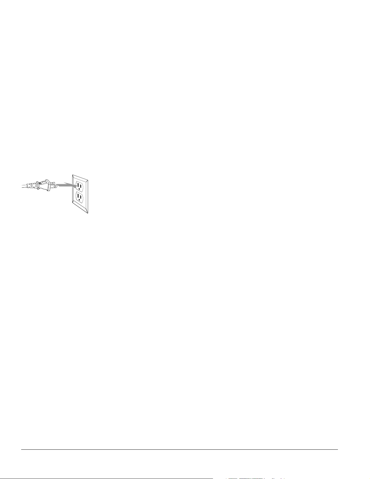
• Do not defeat the safety purpose of the polarized plug (two blades, with one wider than
the other). Connect the plug only to a compatible outlet where you can fully insert the
plug to prevent exposure of the plug blades. If you are unable to insert the plug fully, try
reversing the plug. If the provided plug does not fit your outlet, consult an electrician for
replacement of the outlet.
• Do not place the TV where the power cord can be walked on. This may result in fraying
or damage to the plug.
• Take the following precautions when plugging in the TV. Failure to comply with these
precautions could result in sparks, fire, or electric shock: Do not insert the plug into an
outlet with dust present. Do not insert the plug with wet hands. Insert the plug firmly
into the outlet.
• Unplug the TV during lightning storms or when it will not be used for extended periods.
• Unplug the TV from the wall outlet before cleaning.
• Pull on the plug housing to unplug the power cord; do not pull on the cord.
8 Setting Up the TV
Page 9

Operating the TV Safely
• Except as specifically explained in this User’s Guide, do not attempt to service this product
yourself. Refer all servicing to qualified personnel. Opening or removing covers may
expose you to dangerous voltages or other hazards.
• Unplug the TV from the wall outlet and refer servicing to qualified personnel under the
following conditions:
• When the power cord is damaged or frayed, or if it becomes hot.
• When liquid has been spilled into the TV or if it has been exposed to rain or water.
• If the TV does not operate normally when you follow the operating instructions, or if
it exhibits a distinct change in performance, indicating a need for service.
• If the TV has been dropped or the housing has been damaged.
• Do not stand on the TV or place heavy objects on top of it.
• Do not block the slots and openings in the TV case.
• Never push objects of any kind through the cabinet slots.
• Never insert an object other than a digital photo card in the card slots, or an object other
than paper or an ink cassette into the printer. Do not use sharp tools to remove a card
from a slot or you may damage the slot and card.
• Use only the ink cassette and paper specified for use in the Epson Livingstation printer
(part number V13H151010).
• Never spill liquid of any kind into the TV.
• Do not move or lift the TV by moving or lifting the stand or table supporting it; the TV
may fall and cause injury.
Replacing the Projection Lamp Safely
• Never touch the projection lamp immediately after turning off the TV or you could be
burned.Wait at least 30 minutes after turning off the TV to let the lamp cool down
completely.
• If the lamp has broken, handle the shards carefully to avoid injury.
• The used lamp contains mercury. Please consult your state and local regulations regarding
disposal or recycling. Do not put the lamp in the trash.
• Install the new lamp securely to avoid an electrical short or other damage. Insert the lamp
as described on page 97, pushing it all the way into its slot. Tighten the screws to lock the
lamp securely into place or the lamp will not come on.
• Do not touch the glass on the lamp with your bare hands. This can shorten the lamp life
and obscure the projected image. Use a cloth or glove to handle the new lamp.
• Do not drop the replacement lamp or bump it against any surface; the lamp could be
permanently damaged.
Setting Up the TV 9
Page 10
Outdoor Antenna Installation and Grounding
• It is best to have a professional technician install an antenna on the roof of a structure.
If you install an antenna yourself, be careful to avoid serious injury.
• If an outside antenna is connected through other equipment, be sure the antenna system
is grounded so as to provide protection against voltage surges and built-up static charges.
In the U.S.A., section 810 of the National Electrical Code, ANSI/NFPA 70, provides
information on proper grounding of the mast and supporting structure, grounding of the
lead-in wire to an antenna-discharge unit, size of grounding conductors, location of
antenna-discharge unit, connection to grounding electrode, and requirements for the
grounding electrode.
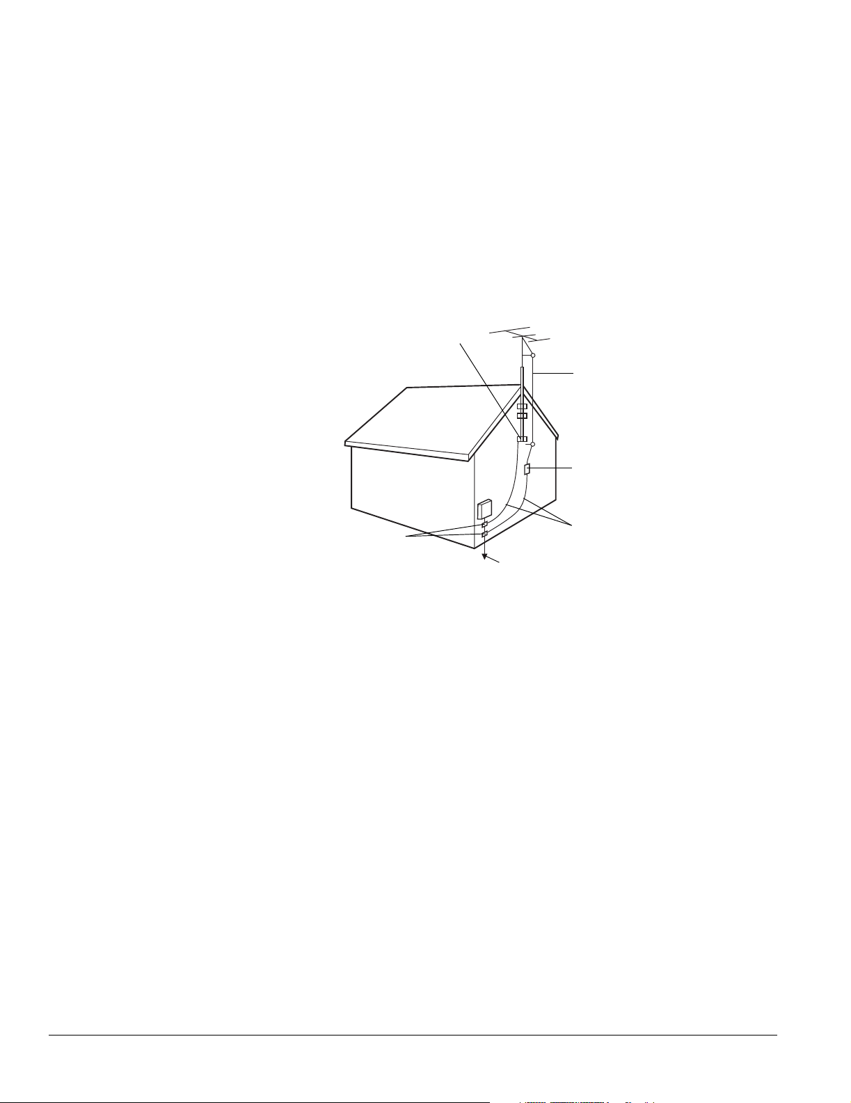
Example of Antenna Grounding in National Electrical Code Instructions
Ground clamp
Antenna lead in wire
Antenna discharge unit
(NEC Section 810-20)
Grounding conductors
Grounding clamps
Power service grounding electrode system
(NEC ART 250, Part H)
(NEC Section 810-21)
• An outdoor antenna system should not be located in the vicinity of overhead power lines/
electric lights or power circuits, or where it can fall onto such power lines or circuits.
When installing an outdoor antenna system, extreme care should be taken to keep it from
touching such power lines or circuits as contact with them might be fatal.
• For added protection during a lightning storm, or when it is left unattended and unused
for long periods of time, unplug the TV from the wall outlet and disconnect the antenna.
This will prevent damage due to lightning and power-line surges.
10 Setting Up the TV
Page 11

Suggested Supports or Stands
You can use an optional Epson TV stand to support your TV. Order part number
V12H003R03 (for the LS47P2) or V12H003R02 (for the LS57P2) from your dealer.
If you use your own stand, make sure it can securely support the TV as follows:
Specification LS47P2 LS57P2
Width of the base
(minimum)
Depth of the base
(minimum)
Weight capacity
(minimum)
47 inches (119 cm) 56 inches (142 cm)
16 inches (41 cm) 18 inches (46 cm)
331 lb (159.0 kg) 331 lb (159.0 kg)
Make sure you place the stand in a location that allows you access to the back of the TV and
provides at least 12 inches (30 cm) of room for ventilation at the sides.
Setting Up the TV 11
Page 12
Caution
Don’t fold the shelf
backwards on its hinge or it
may break.
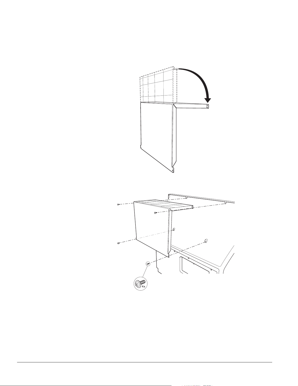
Installing the Set-Top Shelf
The set-top shelf provides a convenient support for a center surround sound speaker or other
component on top of the TV. The shelf can hold up to 11 lb (5 kg).
1 Fold the shelf into an upside-down L-shape with the shorter end on top.
2 Align the holes in the shelf with the holes on the back of the TV.
3 Using a Phillips-head screwdriver, secure the shelf to the TV with the four screws that
came with it. Tighten the screws.
12 Setting Up the TV
Page 13
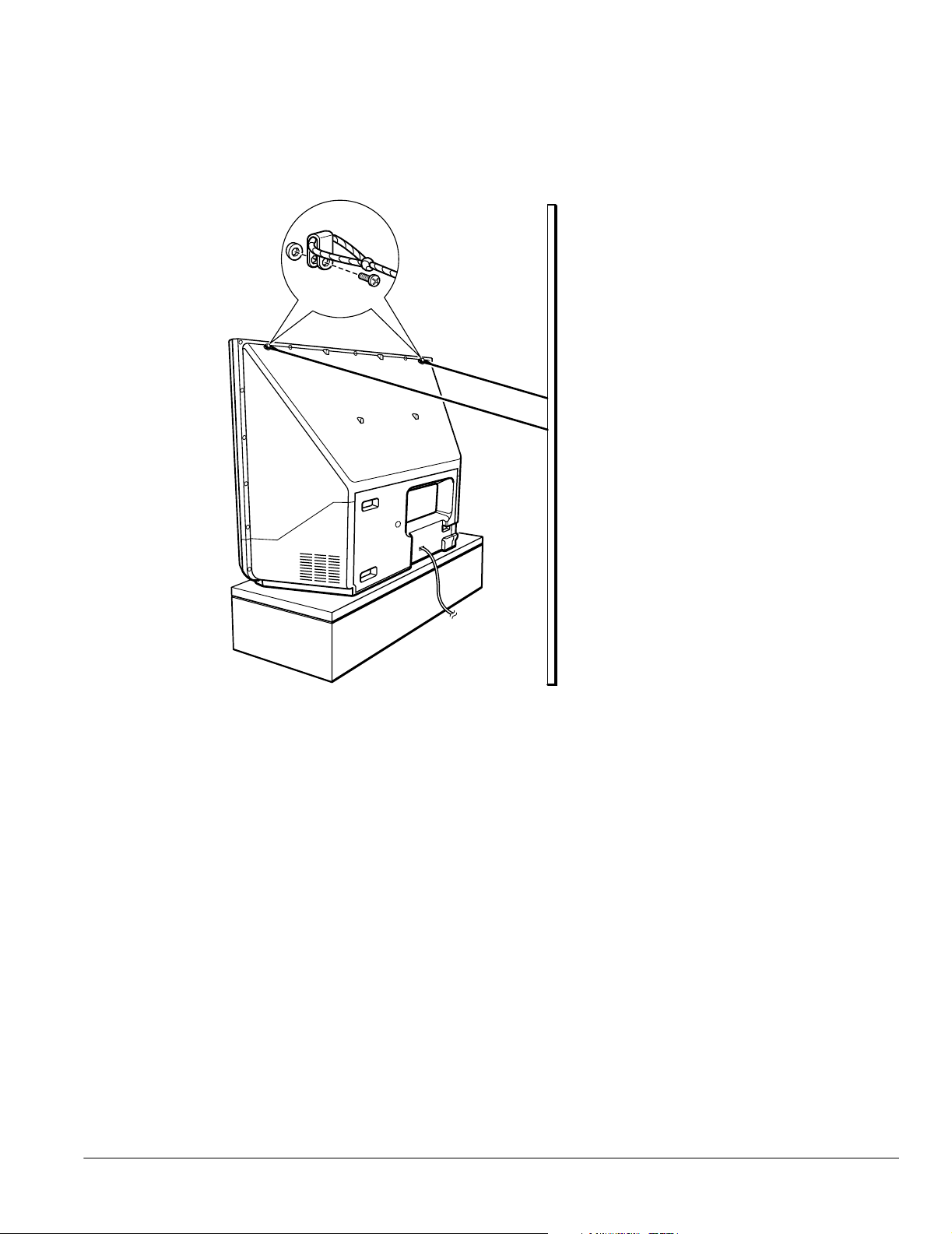
Securing the TV
You may want to secure the TV to a wall or other support so it stays upright on its stand
during an earthquake or other situation. Use wires and screws connected to the outer pair of
holes on the top of the TV to secure the TV to the wall or other support.
Secure the TV
to a wall or
other support
Setting Up the TV 13
Page 14
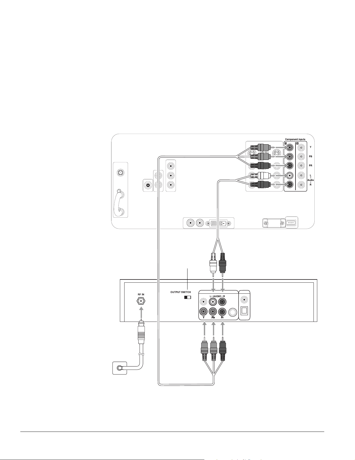
Connecting the HDTV Tuner
If your TV included an HDTV tuner, follow these instructions to connect it.
1 Turn off and unplug your TV and tuner.
2 Slide the OUTPUT SWITCH on the back of the tuner to YPbPr.
Note
For more information on
connecting an antenna,
see the tuner User’s Guide.
3 Connect your antenna’s wall jack to the RF IN jack on the tuner using a standard coaxial
antenna cable.
4 Connect one end of the component video cable (included with your TV) to the
Y (green), PB (blue), and PR (red) connectors on the back of the TV, as shown below. Be
sure to match the colors of the cables to the colors of the connectors.
Audio cable
Set to YPb Pr
HDTV tuner
Component
Wall jack
video cable
5 Connect the other end of the cable to the Y, Pb, and Pr connectors on the tuner.
6 Connect one end of the included RCA-style audio cable (with red/white connectors) to
the L–Audio–R connectors on the back of the TV.
14 Setting Up the TV
Page 15
7 Connect the other end of the cable to the L–Audio–R connectors on the tuner.
8 Plug the TV and tuner into an electrical outlet.
9 See the User’s Guide included with the tuner for instructions on setting up channels,
entering the date and time, and making other basic settings.
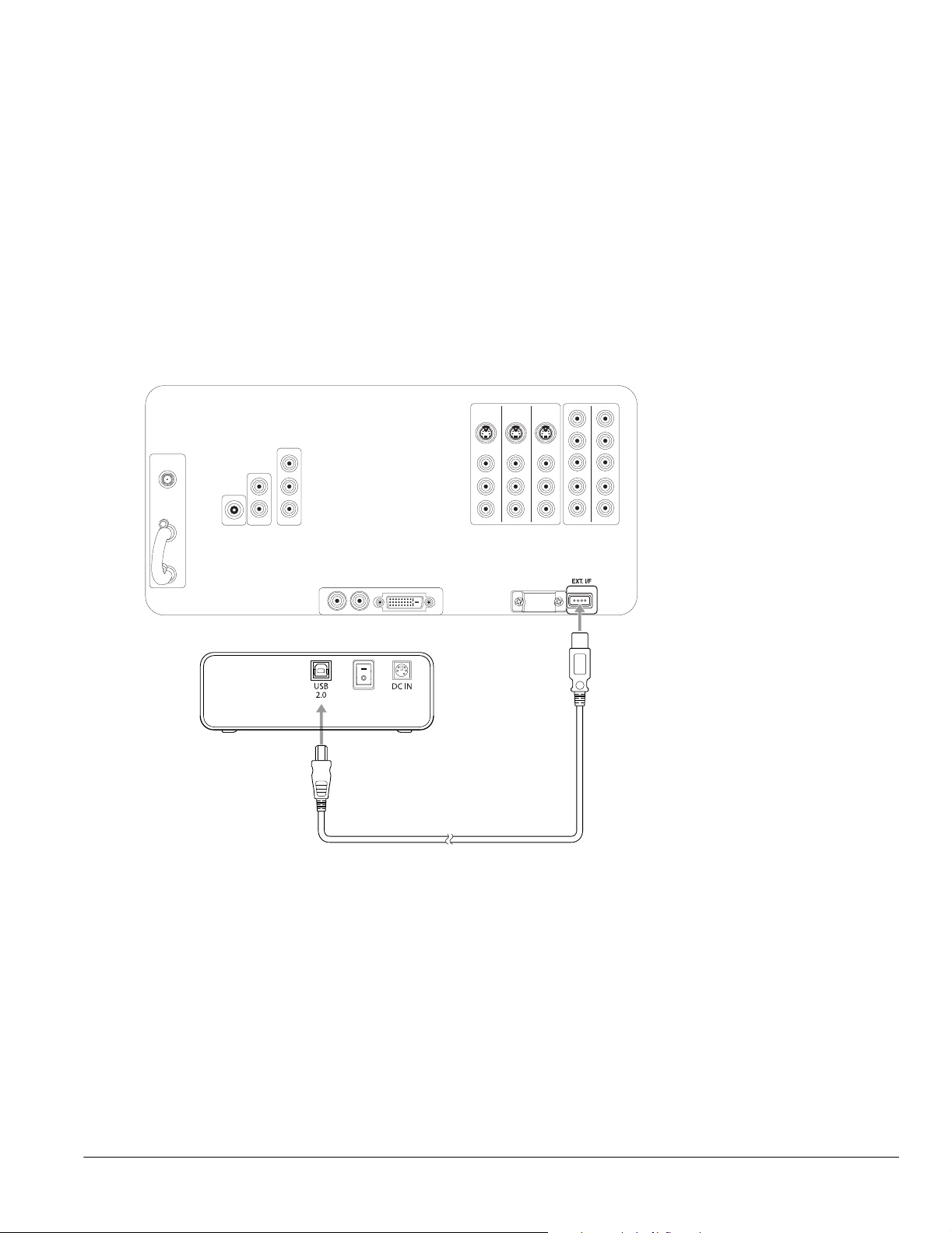
Connecting the CD-R/RW Drive
Follow these instructions to connect the CD-R/RW drive included with your TV.
Note
To use the TV remote
control to operate the
tuner, see page 35. For
more information on using
the tuner, see the User’s
Guide that came with it.
1 Connect the square end of a USB cable to the USB port on your external CD-R/RW
drive.
2 Connect the flat end of the USB cable to the EXT. I/F connector on the back of the TV.
External
CD-R/RW
drive
Note
If you purchased an
optional Epson TV stand,
a mounting bracket is
included for the drive. You
may want to attach the
drive to the stand before
connecting its cables.
Note
The connectors on your
CD-R/RW drive may be in
different positions than
shown.
USB cable
3 Plug the power cord that came with the CD-R/RW into the drive’s power supply, then
connect the cords to the drive and an electrical outlet.
4 Turn on the CD-R/RW drive by flipping the power switch in back.
Setting Up the TV 15
Page 16

Note
For a description of all the
available connectors on
the front and back panels,
see the inside back cover
of this book.
Connecting Other Equipment
You can connect the TV to a variety of equipment. Follow the steps in the applicable sections
below, depending on the equipment you’re connecting and the type of connector or service
you’re using.
• “Antenna or Direct Cable TV Connection” on page 17
• “Cable Box Connections” on page 18
• “Satellite Receiver Connection” on page 20
• “DVD Player With a DVI Connection” on page 21
• “DVD Player With Component Video Connection” on page 22
• “DVD Player With an S-Video Connection” on page 23
• “VCR Connection” on page 24
• “VCR and Cable Service (Without Cable Box) Connection” on page 25
• “VCR and Cable Box Connection” on page 26
• “VCR and Satellite Receiver Connection” on page 27
• “Stereo Amplifier Connection” on page 29
• “PC or Game Console Connection” on page 30
• “Camcorder, Digital Camera, or Other Portable Video Connection” on page 31
• “Other Optional Device Connections” on page 32
16 Setting Up the TV
Page 17
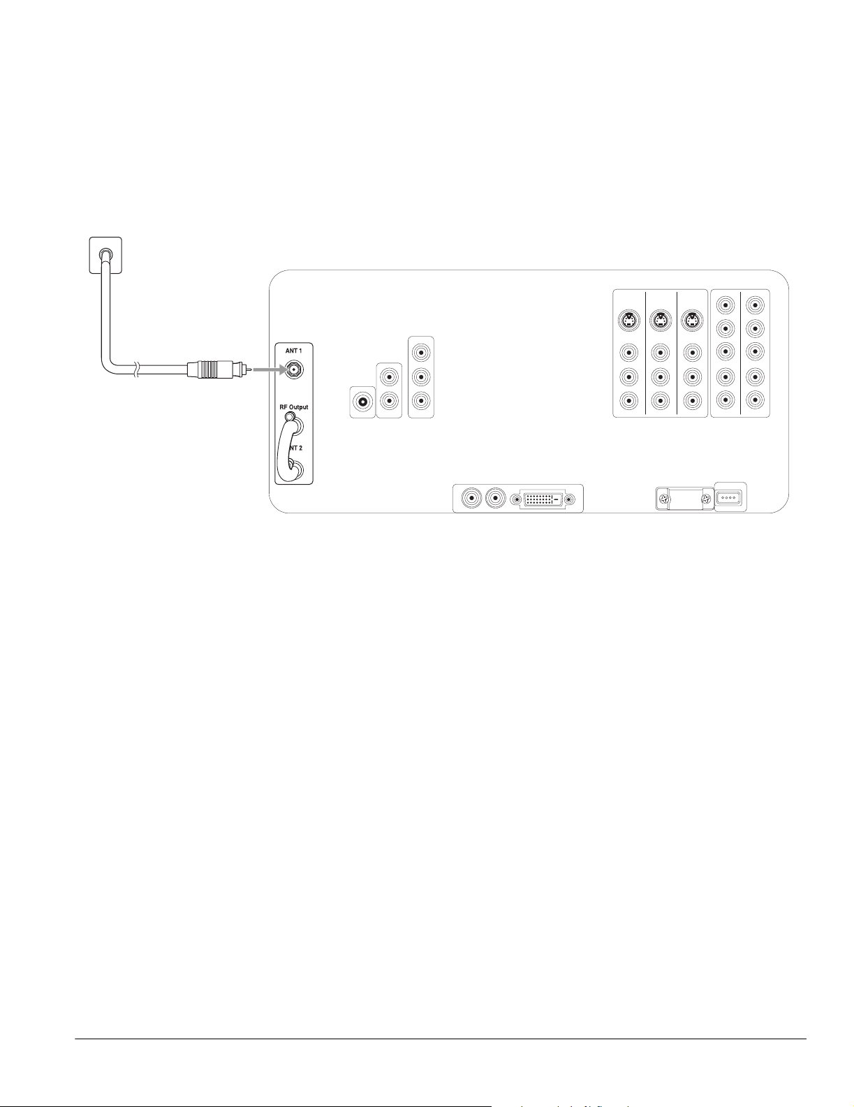
Antenna or Direct Cable TV Connection
Connect the TV to an outside antenna or to your cable system using a 75-ohm coaxial cable.
Connect the cable coming into the house to the ANT 1 connector on the back of the TV.
If your coaxial cable has a screw-type connector on the end, secure it by turning the end
clockwise.
Wall jack
If you’ll also be attaching a VCR to the TV, you need to use a different connection method so
you can record TV programs. See “VCR and Cable Service (Without Cable Box)
Connection” on page 25.
Note
If you have an older home,
you may have a 300-ohm
twin lead cable. If so, you
also need an antenna
connector or U/V splitter to
connect it to your TV. Keep
the twin lead cable as far
away from your TV as
possible to reduce the
radio noise that may cause
signal problems.
Setting Up the TV 17
Page 18

Note
Before connecting a cable
box to the TV, be sure to
read any instructions that
came with the cable box.
Wall jack
Cable Box Connections
The connection method differs, depending on the type of cable box you have. Your cable box
may unscramble signals for all of your channels or it may unscramble only some of them.
If you’ll also be attaching a VCR to the TV, you need to use a different connection method so
you can record TV programs. See “VCR and Cable Box Connection” on page 26.
Cable Box Unscrambles All Channels
If your cable box unscrambles signals for all of your channels, connect it as follows:
1 Connect the cable coming into the house to the IN connector on the cable box.
2 Connect one end of a coaxial cable to the OUT connector on the cable box.
3 Connect the other end of the coaxial cable to the ANT 1 connector on the back of the
TV.
If your coaxial cable has a screw-type connector on the end, secure it by turning the end
clockwise.
Cable box
Coaxial cable
18 Setting Up the TV
Page 19
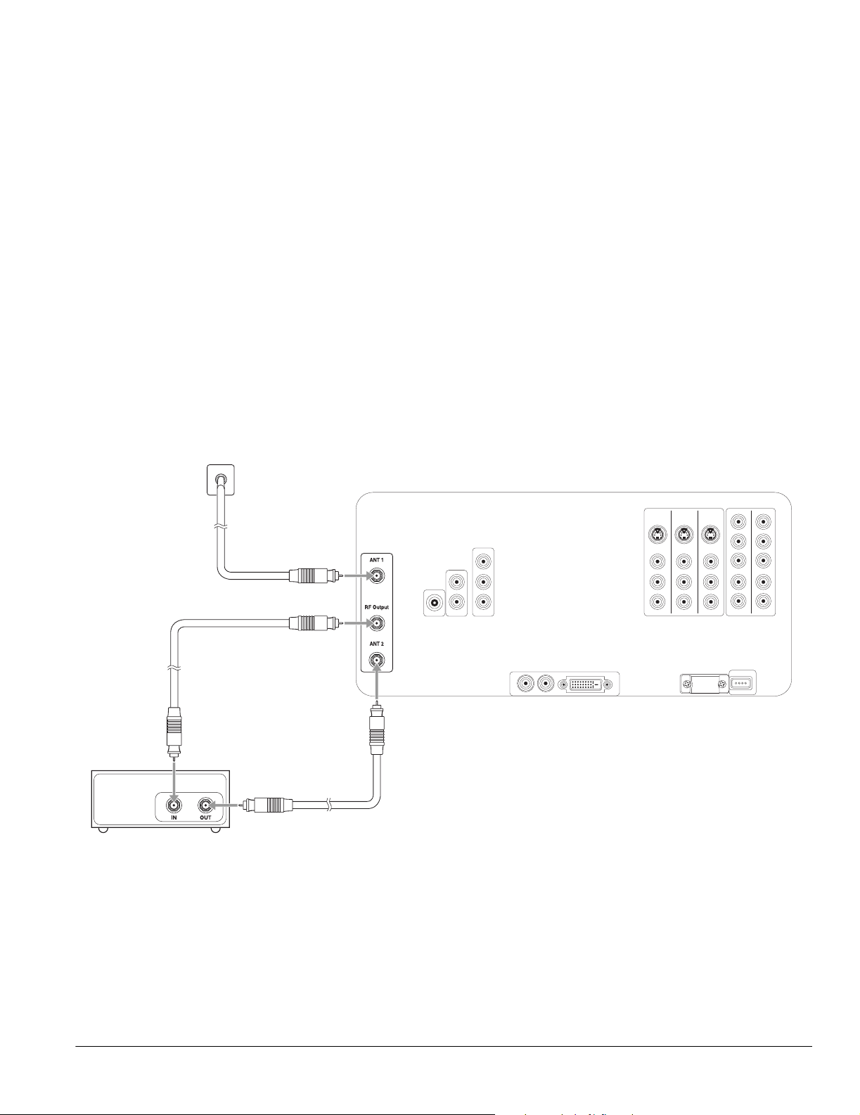
Cable Box Unscrambles Only Some of Your Channels
If your cable box unscrambles signals for only some of your channels, connect it as follows:
1 Connect the cable coming into the house to the ANT 1 connector on the back of the TV.
2 Remove the jumper cable connected to both the RF Output and ANT 2 connectors on
the back of the TV. Retain the cable.
3 Connect one end of a coaxial cable to the RF Output connector on the back of the TV.
4 Connect the other end of the coaxial cable to the IN connector on the cable box.
If your coaxial cable has a screw-type connector on the end, secure it by turning the end
clockwise.
5 Connect another coaxial cable to the OUT connector on the cable box.
6 Connect the other end of the coaxial cable to the ANT 2 connector on the back of the
TV.
7 Be sure to turn on use of the TV’s ANT 2 port, as described on page 47.
Wall jack
Note
Be sure to retain the jumper
cable in case you change
your TV connections later.
You’ll need to connect it
again in certain
connection schemes to
provide the channel
zapping feature.
Cable box
Coaxial cables
Setting Up the TV 19
Page 20
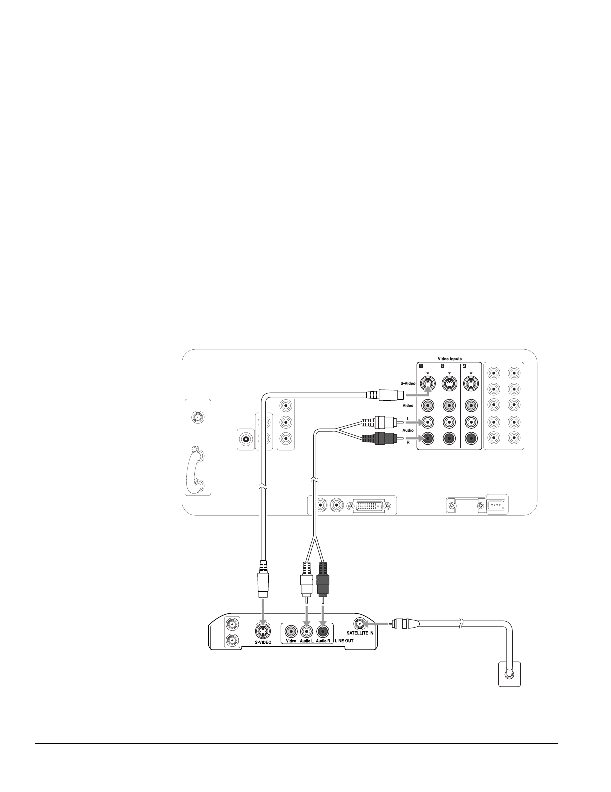
Satellite Receiver Connection
If you’ll also be attaching a VCR to the TV, you need to use a different connection method so
you can record TV programs. See “VCR and Satellite Receiver Connection” on page 27.
Note
If your satellite receiver
doesn’t have an S-video
connector, you can
connect a video cable
(yellow) to the Video
connectors instead of the
S-video cable using these
instructions.
It’s best to connect your
satellite receiver to the
S-Video connectors on the
back of the TV to free up
the S-Video connector on
the front to connect a
camcorder.
1 Turn off and unplug your TV and your satellite receiver.
2 Connect the satellite antenna cable coming into your house to the Satellite In connector
on your satellite receiver.
3 Connect one end of an S-video cable to one of the S-Video connectors on the back of
the TV or to the one on the front of the TV beneath the connector cover.
(If your satellite receiver uses a DVI connection, connect a DVI cable instead, as shown
on page 21. If it uses a component video connection, connect it as shown on page 22.)
4 Connect the other end of the S-video cable to the S-Video connector on your satellite
receiver.
5 Connect one end of a standard, red/white audio cable to the corresponding Video
Inputs R and L Audio connectors on the back or front of the TV.
6 Connect the other end of the audio cable to the R and L Audio Line Out connectors on
your satellite receiver.
20 Setting Up the TV
Audio cableS-video cable
Satellite receiver
Wall jack
7 Plug your TV and satellite receiver back into their electrical outlets.
Page 21
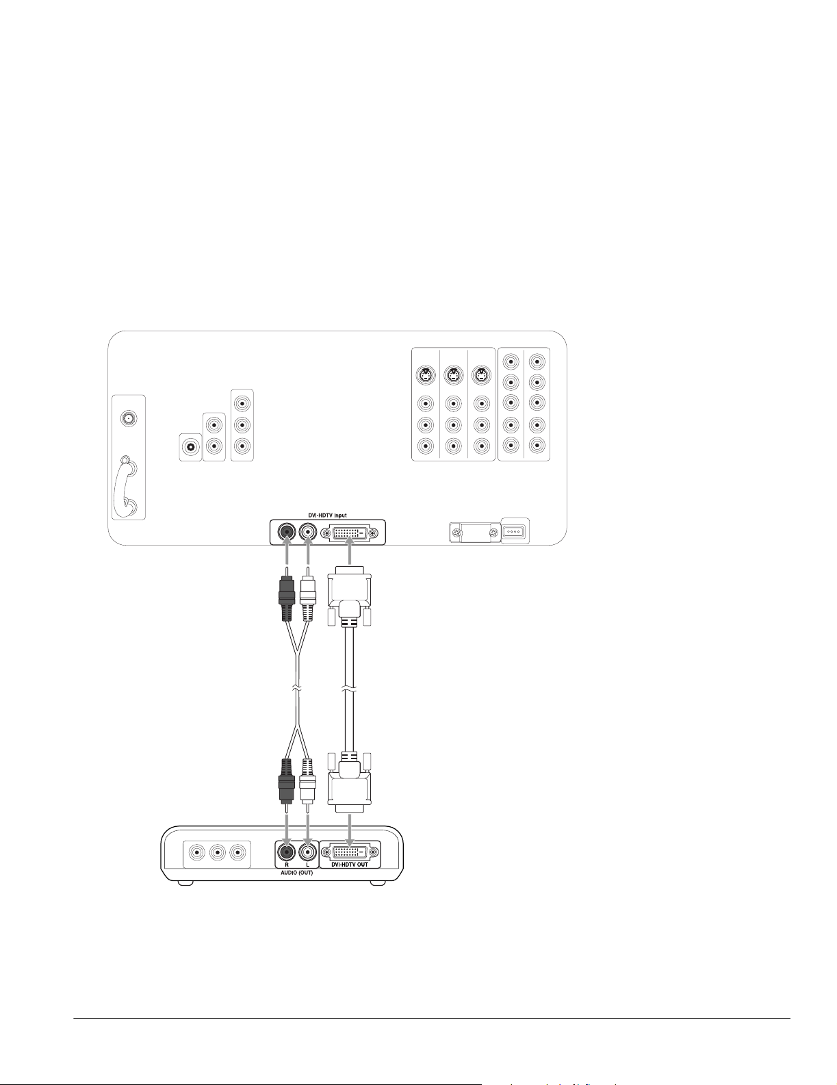
DVD Player With a DVI Connection
1 Turn off and unplug your TV and your DVD player.
2 Connect one end of a DVI-HDTV cable to the DVI-HDTV Input connector on the
back of the TV.
3 Connect the other end of the DVI-HDTV cable to the DVI-HDTV OUT connector on
your DVD player.
4 Connect one end of a standard, red/white audio cable to the DVI-HDTV Input R and L
Audio connectors on the back of the TV.
5 Connect the other end of the audio cable to the R and L Audio Out connectors on your
DVD player.
DVI-HDTV cableAudio cable
DVD player
6 Plug your TV and DVD player back into their electrical outlets.
Note
If you have any trouble
switching to the DVI input
source, make sure you
didn’t turn off the Use of
DVI Input setting. See
page 43 for details.
Setting Up the TV 21
Page 22
Note
The connectors may be
labeled Y, B-Y, R- Y, o r Y, C b ,
Cr, or Y, Pb, Pr on your DVD
player, so just match the
connector colors.
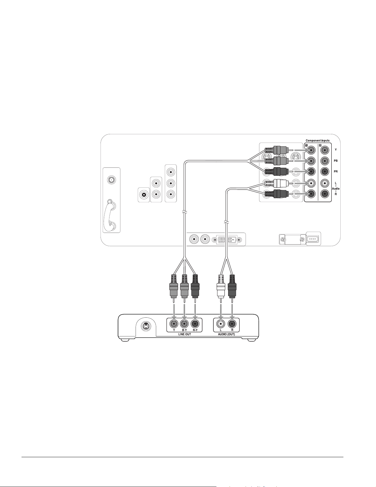
DVD Player With Component Video Connection
1 Connect one end of the component video cable to any available set of Y (green), PB
(blue), and PR (red) connectors on the back of the TV.
2 Connect the other end of the component video cable to the corresponding color
Component Video Out connectors on your DVD player.
3 Connect one end of a standard, red/white audio cable to the corresponding
Component Input R and L Audio connectors on the back of the TV.
4 Connect the other end of the audio cable to the R and L Audio Line Out connectors on
your DVD player.
cable
DVD player
Audio cableComponent video
22 Setting Up the TV
Page 23
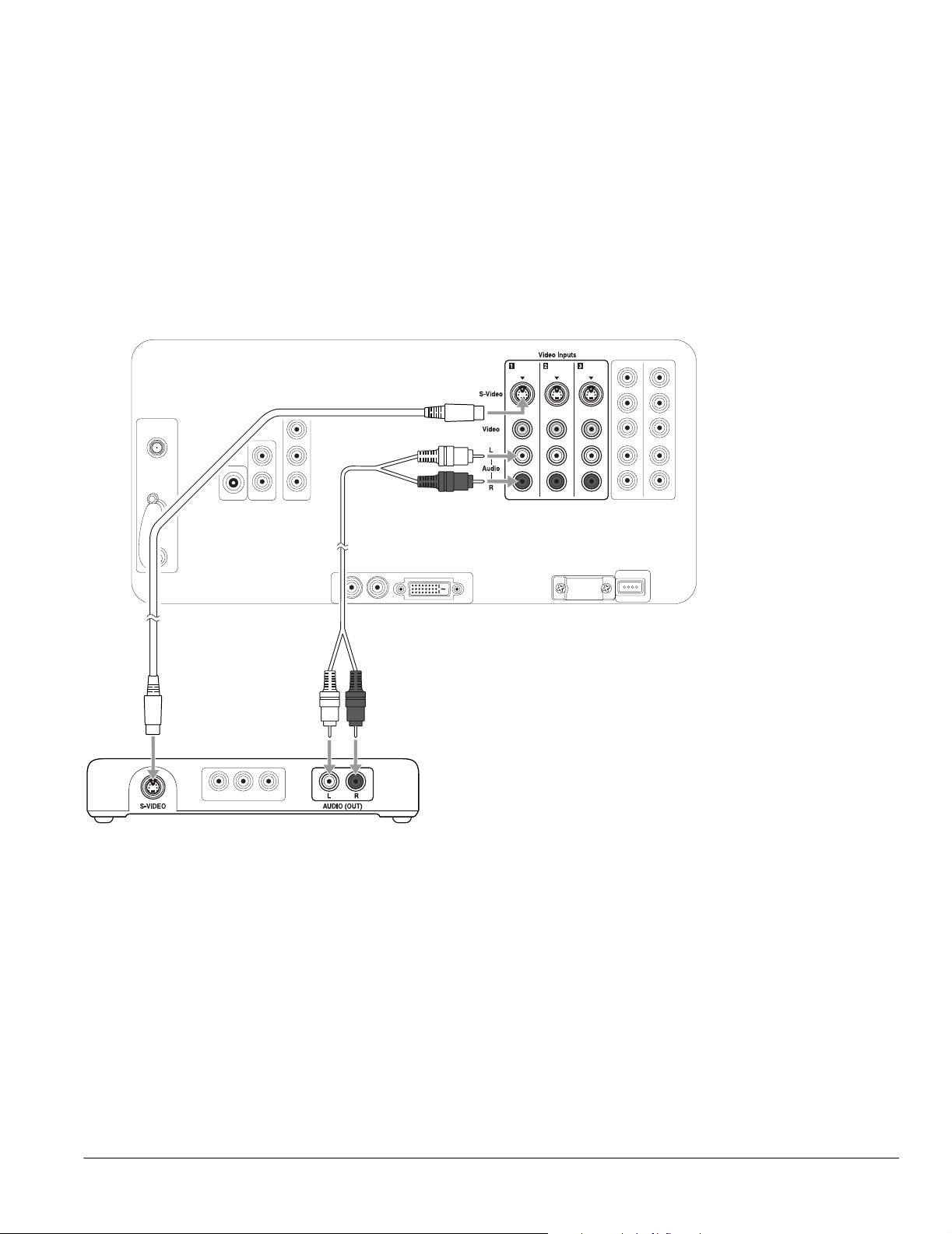
DVD Player With an S-Video Connection
1 Connect one end of an S-video cable to one of the S-Video connectors on the back of
the TV or to the one on the front of the TV beneath the connector cover.
2 Connect the other end of the S-video cable to the S-Video connector on your DVD
player.
3 Connect one end of a standard, red/white audio cable to the corresponding Video
Inputs R and L Audio connectors on the back or front of the TV.
4 Connect the other end of the audio cable to the R and L Audio Line Out connectors on
your DVD player.
Note
If your DVD player doesn’t
have an S-video
connector, you can
connect a video cable
(yellow) to the Video
connectors instead of the
S-video cable using these
instructions.
It’s best to connect your
DVD player to the S-video
connectors on the back of
the TV to free up the
S-video connector on the
front to connect a
camcorder.
S-video cable
DVD player
Audio cable
Setting Up the TV 23
Page 24

Note
If your VCR doesn’t have
an S-video connector, you
can connect a video
cable (yellow) to the Video
connectors instead of the
S-video cable using these
instructions.
It’s best to connect your
VCR to the S-Video
connectors on the back of
the TV to free up the
S-Video connector on the
front to connect a
camcorder.
VCR Connection
Follow these steps to connect a VCR by itself.
If you’re connecting a cable, cable box, or satellite receiver along with the VCR, see the
instructions in the sections following this one instead.
1 Connect one end of an S-video cable to one of the S-Video connectors on the back of
the TV or to the one on the front of the TV beneath the connector cover.
2 Connect the other end of the S-video cable to the S-Video connector on your VCR.
3 Connect one end of a standard, red/white audio cable to the corresponding Video
Inputs R and L Audio connectors on the back or front of the TV.
4 Connect the other end of the audio cable to the R and L Audio Line Out connectors on
your VCR.
24 Setting Up the TV
Audio cableS-video cable
VCR
Page 25
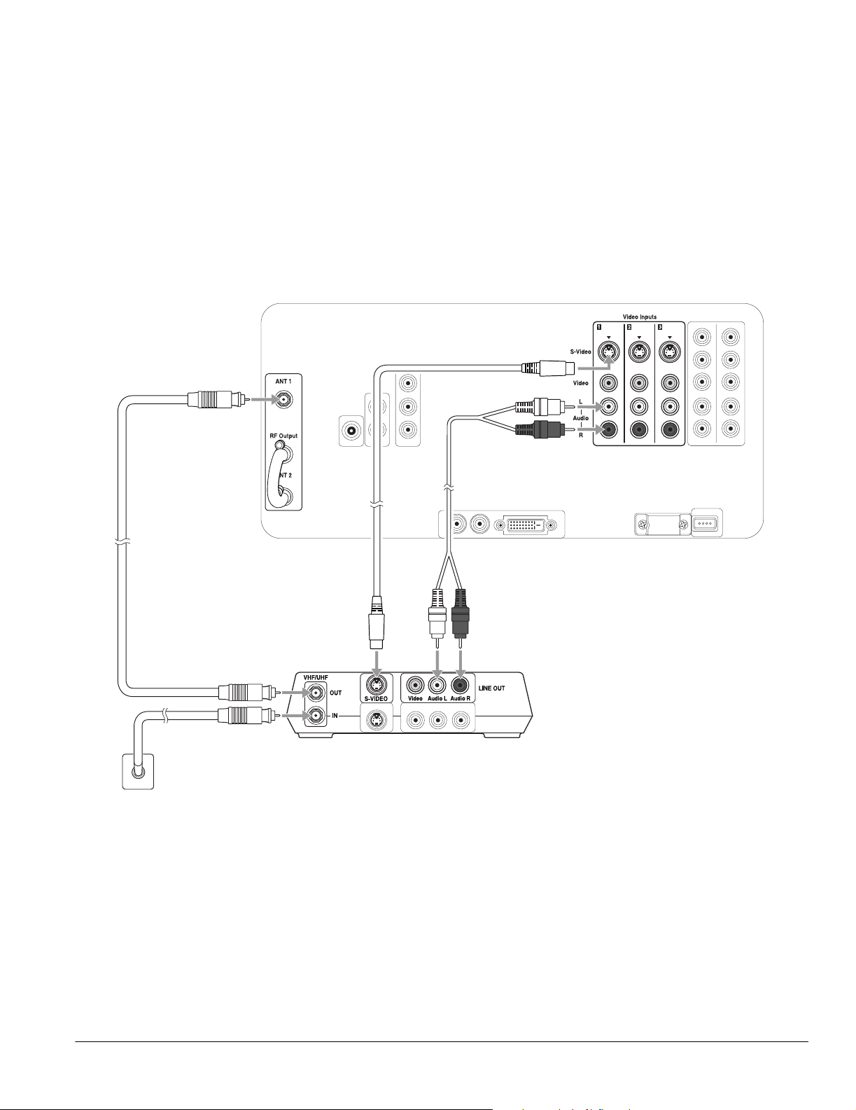
VCR and Cable Service (Without Cable Box) Connection
1 Connect the VCR as described in “VCR Connection” on page 24.
2 Connect the cable coming into the house to the IN connector on the VCR.
3 Connect one end of a coaxial cable to the OUT connector on the VCR.
4 Connect the other end of the coaxial cable to the ANT 1 connector on the back of the
TV.
If your coaxial cable has a screw-type connector on the end, secure it by turning the end
clockwise.
Wall jack
cable
Audio cableS-video cableCoaxial
VCR
Setting Up the TV 25
Page 26
Note
Before connecting a cable
box to the TV, be sure to
read any instructions that
came with the cable box.
Note
Be sure to retain the jumper
cable in case you change
your TV connections later.
You’ll need to connect it
again in certain
connection schemes to
provide the channel
zapping feature.
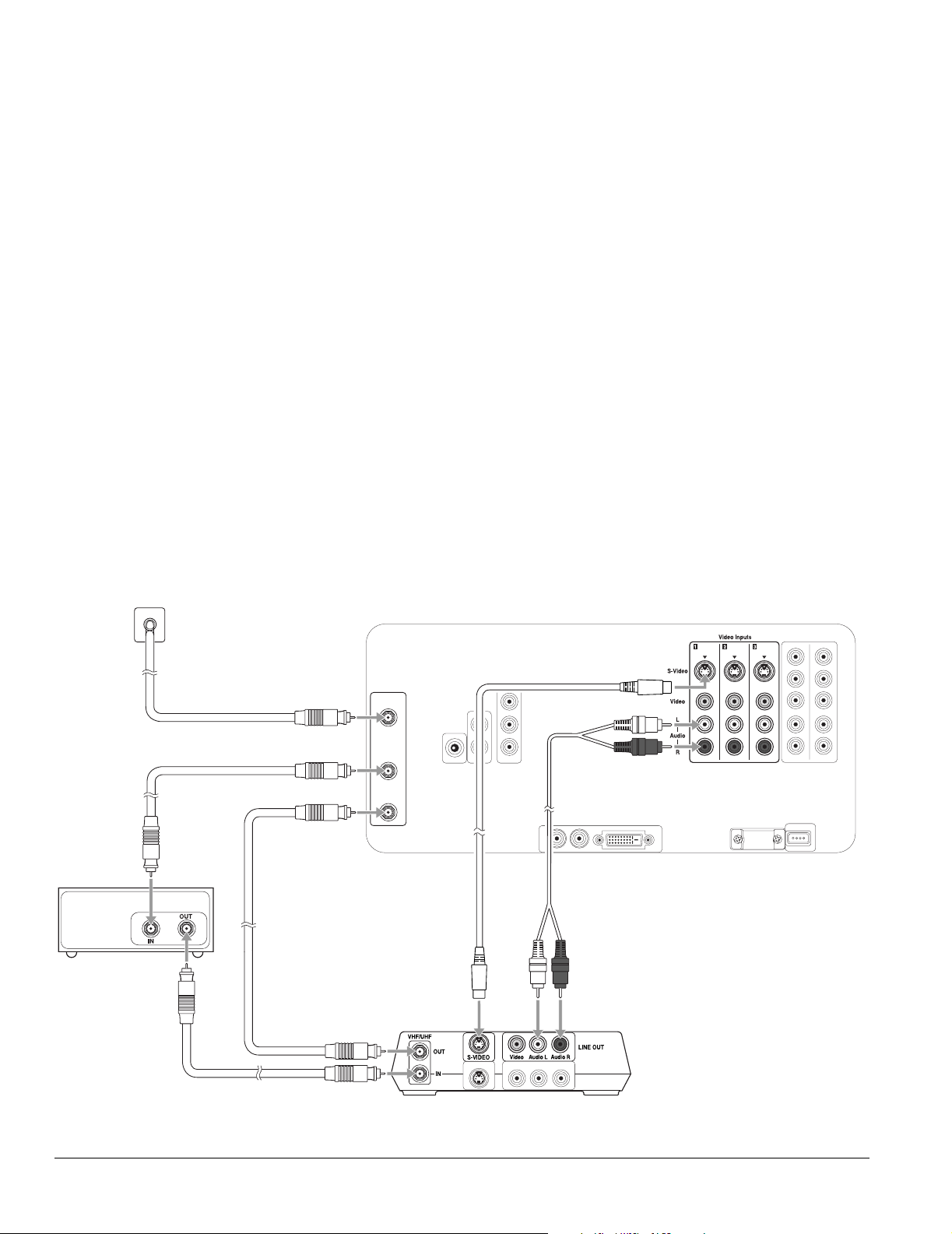
VCR and Cable Box Connection
1 Turn off and unplug your TV, VCR, and cable box.
2 Connect the VCR as described in “VCR Connection” on page 24.
3 Connect the cable line coming into the house to the ANT 1 connector on the back of the
TV.
4 Remove the jumper cable connected to both the RF Output and ANT 2 connectors on
the back of the TV. Retain the cable.
5 Connect one end of a coaxial cable to the RF Output connector on the back of the TV.
6 Connect the other end of the coaxial cable to the IN connector on the cable box. If your
coaxial cable has a screw-type connector on the end, secure it by turning the end
clockwise.
7 Connect another coaxial cable to the OUT connector on the cable box.
8 Connect the other end of the coaxial cable to the IN connector on the VCR.
9 Connect another coaxial cable to the OUT connector on the VCR.
10 Connect the other end of the coaxial cable to the ANT 2 connector on the back of the
TV.
Cable box
11 Be sure to turn on use of the TV’s ANT 2 port, as described on page 47.
Wall jack
ANT 1
RF Output
ANT 2
Coaxial
cables
Audio cableS-video cable
VCR
26 Setting Up the TV
12 Plug your TV, VCR, and cable box back into an electrical outlet.
Page 27

VCR and Satellite Receiver Connection
1 Turn off and unplug your TV, VCR, and satellite receiver.
2 Connect the VCR as described in “VCR Connection” on page 24.
3 Connect the satellite antenna cable to the Satellite In connector on your satellite
receiver.
4 Connect one end of an S-video cable to one of the S-video connectors on your satellite
receiver.
(If your satellite receiver uses a DVI connection, connect a DVI cable instead, as shown
on page 21. If it uses a component video connection, connect it as shown on page 22.)
5 Connect the other end of the S-video cable to one of the S-video connectors on your
VCR.
6 Connect one end of a standard, red/white audio cable to the R and L Audio Line Out
connectors on your satellite receiver.
7 Connect the other end of the audio cable to the R and L Audio Line In connectors on
your VCR.
Note
Before connecting a
satellite receiver to the TV,
be sure to read any
instructions that came with
the receiver.
Note
If your satellite receiver
doesn’t have an S-video
connector, you can
connect a video cable
(yellow) to the Video
connectors instead of the
S-video cable using these
instructions.
It’s best to connect your
satellite receiver to the
S-Video connectors on the
back of the TV to free up
the S-Video connector on
the front to connect a
camcorder.
Setting Up the TV 27
Page 28
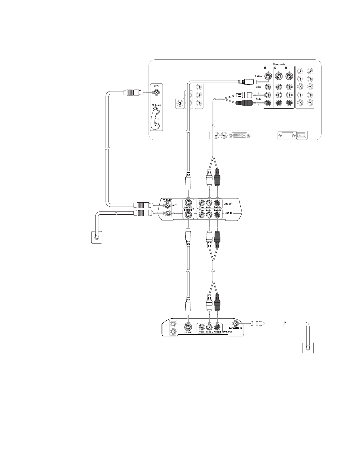
8 If your satellite service does not include local channels, you can also connect an outside
antenna or cable service line to the VHF/UHF IN connector on the VCR. Then connect a
coaxial cable to the VHF/UHF OUT connector and to the ANT 1 connector on the back
of your TV.
Audio cableS-video cable
Coaxial
cable
VCR
Wall jack
Audio cableS-video cable
Satellite
receiver
9 Plug your TV, VCR, and satellite receiver back into an electrical outlet.
Wall jack
28 Setting Up the TV
Page 29
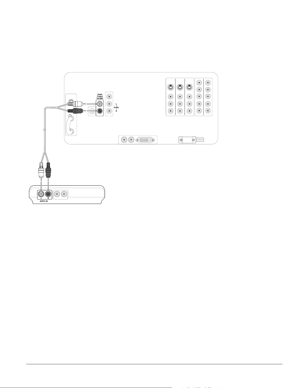
Stereo Amplifier Connection
1 Connect one end of a standard, red/white audio cable to the R and L Audio Output
Var ia bl e connectors on the back of your TV.
2 Connect the other end of the audio cable to the R and L Audio Line Input connectors
on your stereo amplifier.
Audio cable
Note
You can’t connect external
speakers to the TV directly;
you must connect them to
a stereo amplifier.
For best sound quality, you
may want to connect the
amplifier directly to your
audio sources (DVD player,
HDTV tuner, etc.).
Stereo amplifier
3 Turn the TV’s speaker volume all the way up to the maximum level. Then use your
amplifier remote control to adjust the volume.
Setting Up the TV 29
Page 30
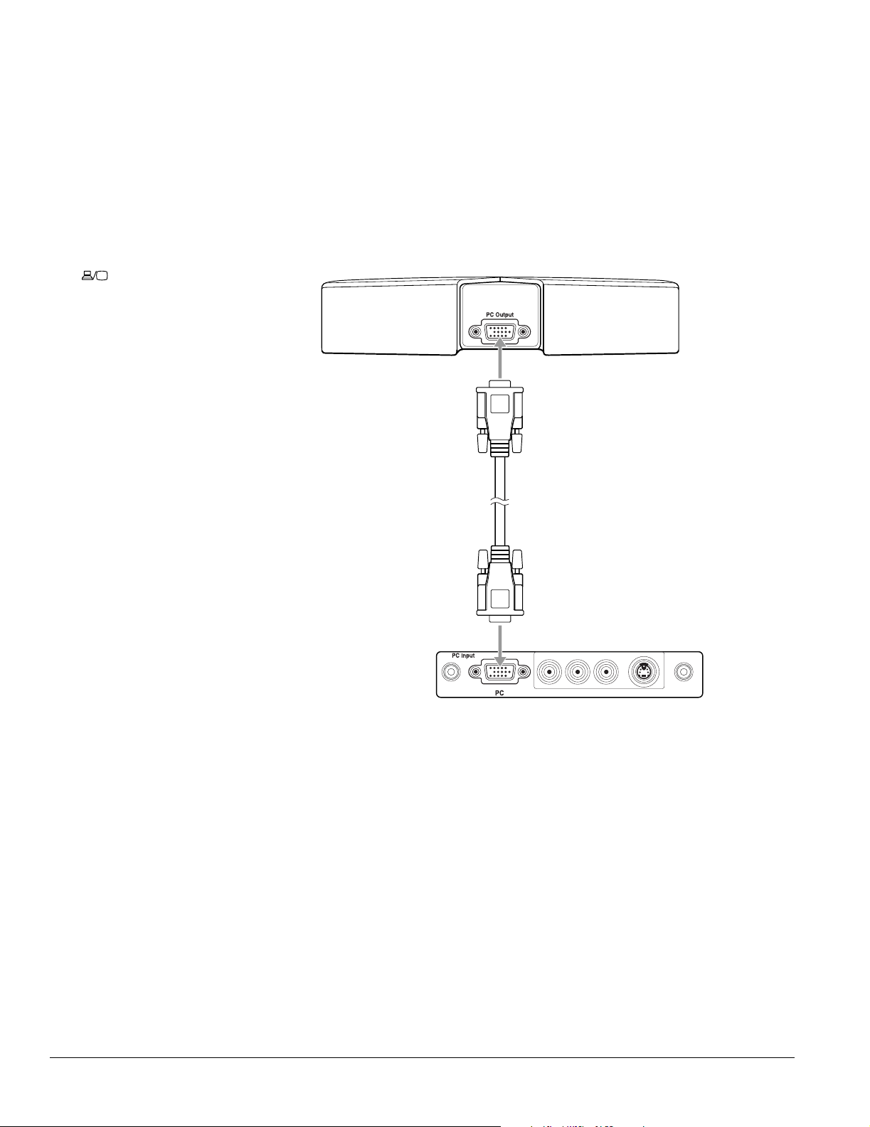
PC or Game Console Connection
1 For a PC, connect one end of a Dsub15 RGB for PC cable to the monitor or PC output
connector on the back of your PC.
For a game console, just use the cable that came with the console.
Note
To display images on your
laptop monitor and the TV
screen at the same time,
you may need to press the
Fn or button on your
laptop. See your computer
documentation for details.
If you have any trouble
switching to the PC input
source, make sure you
didn’t turn off the Use of PC
Input setting. See page 43
for details.
2 Connect the other end of the cable to the PC connector on the front of the TV.
3 Connect any necessary audio cables to your device and to the Video Inputs R and L
Audio connectors on the front of the TV.
PC or game
console
Dsub15 RGB for PC or
game console cable
TV’s front
connector
panel
30 Setting Up the TV
Page 31

Camcorder, Digital Camera, or Other Portable Video Connection
It’s best to connect a portable video device to the S-Video or Video connector on the front
of the TV; however, you can use the connectors on the back. These instructions use a
camcorder as an example.
1 Connect one end of an S-video cable to the S-Video connector on the front of the TV
beneath the connector cover.
2 Connect the other end of the S-video cable to the S-Video connector on your
camcorder.
3 Connect one end of a standard, red/white audio cable to the Video Inputs R and L
Audio connectors on the front of the TV.
Note
If your device doesn’t have
an S-video connector, you
can connect a video
cable (yellow) to the Video
connector instead of the
S-video cable using these
instructions.
4 Connect the other end of the audio cable to the R and L A/V Output connectors on
your camcorder.
S-video cable
Audio cable
TV’s front
connector
panel
4
Video Inputs
S-VideoR–Audio–L
If you’re connecting a
device with mono audio,
connect the left (white)
cable to the L A/V Output
connector on your device
and the L Audio connector
on the front of the TV.
If you connect your device
to a video connector on
the TV’s front panel, select
Video 4 as the input source
using the TV/Video button.
Setting Up the TV 31
Page 32

Note
When you connect
headphones, the TV
speakers are turned off, but
sound is still audible from
any audio source you have
connected to the TV.
Other Optional Device Connections
Headphones
Connect headphones to the Headphone connector on the front of the TV.
TV’s front
connector
panel
Remote IR Repeater
Connecting a remote IR repeater lets you control other equipment (such as a VCR or DVD
player) by using its remote control pointed at the TV’s remote control receiver on its front
panel.
Connect the remote IR repeater to the Remote-out connector on the back of the TV using
the cable that came with the repeater.
Mini-jack
cable
32 Setting Up the TV
Remote IR
repeater
Page 33

Preparing the Remote Control
Before you can use the remote control, you need to insert the batteries and make sure you aim
it correctly. For a description of its functions when using it to operate the TV, see the inside
front cover of this book; for instructions on using it with the HDTV tuner, see page 35.
Inserting the Batteries
The remote control uses two AA batteries. You’ll need to install the batteries that came with
your TV before you can use the remote control.
1 Press in on the top of the battery cover on the back of the remote control. Then slide the
cover down and off the remote.
2 Insert the batteries as shown below, making sure the + and – ends face the right way. Then
push them down flat.
Caution
When you replace the
batteries, take the
following precautions:
Don’t mix old and new
batteries.
If the batteries leak, wipe
away the battery fluid with
a soft cloth. If fluid gets on
your hands, wash them
immediately.
Remove the batteries if you
won’t be using the TV for
awhile.
Dispose of old batteries in
accordance with the
regulations in your area.
+ ends
3 Place the cover into the grooves and slide the cover all the way up until it clicks into place.
Setting Up the TV 33
Page 34

Operating the Remote Control
Aim the remote control at the front of the TV, within about a 25° horizontal angle to the left
or right and a 15° vertical angle up or down from the remote receiver.
Receiver
Make sure the room lighting is not too bright and not shining directly on the remote control
or the TV receiver window. Keep the transmitter area on the top of the remote and the TV
receiver window clean.
To turn off the remote control’s beeping sound, hold down the Menu button for 2 seconds,
until the remote control light stops flashing. Then press the Vo lum e down button. (To turn
it back on, hold down the Menu button for 2 seconds, until the remote control light stops
flashing. Then press the Vol um e up button.)
Remote Control Information
The TV may not respond to remote control commands under the following conditions:
• There is an object between the remote control IR emitter and the IR receiver on the TV.
• Ambient light is too bright.
• Certain types of fluorescent lighting are used.
• A strong light source shines into the IR receiver.
• Other equipment that emits infrared energy, such as a radiant room heater, is in the room.
If these conditions cause problems for your TV’s remote control, try the following:
34 Setting Up the TV
• The remote control’s batteries may be low on power; replace them.
• Dim the ambient lighting and/or turn off any fluorescent lights.
• Close any window coverings and/or move the TV out of direct sunlight.
• Turn off other equipment that emits infrared energy.
Page 35

Controlling the HDTV Tuner With the Remote Control
You can use the TV’s remote control to operate the HDTV tuner that came with your TV
(tuner not included in all areas). That way, you only need to keep one remote control at hand.
1 Move the equipment switch at the top of the TV
remote control to the STB1 (Set-Top Box 1) position.
This position lets you operate the HDTV tuner.
Powe r
STB1TV
STB2 VCR DVD
Slide to STB1
Note
You can also program the
remote to operate other
equipment you have
connected to the TV. See
page 36 for instructions.
2 Use the remote control to operate the tuner, as
described below. See the tuner User’s Guide for details.
Power button
Turns the tuner on and off
Menu button
Press to enter or exit the menu system
Number buttons
Use to enter channel numbers
and passwords, and to set the
time. To enter a digital
subchannel (such as 28–1 or 28-2),
enter the main channel number
(such as 28), press the – key, then
enter the subchannel (1, 2, etc.).
Press Ch Enter to complete the
selection.
Power
STOP REW PLAY FF
Photo View
Photo
Zoom
STB1TV
STB2 VCR DVD
PAUSEREC SKIP
Freeze
Menu
Select
Prev.
132
456
789
TV/Video
Vol.
Next
Enter
Select
0
Mute Favorite
Ch
Print
Exit
Ch
Enter
Rotate
PAUSEREC SKIP
STOP REW PLAY FF
Exit button
Exits the menu system or returns to
the previous menu screen
Navigation buttons
Moves highlight up, down, left, or right in
menus. Press Enter to accept a selection.
Vol. and Mute buttons
Control the sound
MTS button (Multichannel
Television Stereo)
Selects an alternate audio track
or language
Guide button
Displays the electronic program
MTS
Guide
Ch Prev.
SleepSwapAspect POP
Ch Display
Info
Channel up/down button
Moves the channel up or down
Ch. Display/Info button
Displays the channel and
programming information
guide
When you want to operate the TV again, slide the equipment switch on the remote control
back to the TV position.
Setting Up the TV 35
Page 36

Note
If there are multiple codes
listed for your equipment
manufacturer and the first
one you choose doesn’t
work, try another code.
Controlling Other Equipment With the Remote Control
You can program the remote control to operate other home theater equipment, such as a
DVD player, VCR, or satellite receiver. That way, you can use just one remote control when
watching movies or TV programs.
After you replace the
remote control’s batteries,
you will still be able to use it
to operate the TV and
tuner. But you will have to
re-enter the codes for any
other equipment that you
want to control.
Light
Equipment
switch
Power
STB1TV
STB2 VCR DVD
PAUSEREC SKIP
STOP REW PLAY FF
Freeze
Photo View
Menu
Select
Photo
Zoom
Prev.
Next
Enter
Select
132
456
789
0
TV/Video
Mute Favorite
Vol.
Ch
Print
Exit
Rotate
Ch
Enter
Control
buttons
Menu
button
Number
buttons
First you must program your remote control so it knows what kind of equipment you’re using.
You do this by entering a code that corresponds to the equipment and its manufacturer.
Programming the Remote Control
1 Look up the three-digit code for your equipment and manufacturer in the tables
beginning on page 37.
2 Slide the equipment switch on the top of the remote control to the setting for your
equipment type. For example, to enter a DVD player code, slide the switch to the DVD
setting. If you reprogram the STB1 setting, you won’t be able to use the remote control to
operate the HDTV tuner that may have come with your TV, unless you re-enter the
tuner’s code (101).
3 Hold down the Menu button on the remote control until its light comes on (about 2 to
3 seconds).
4 Enter the three-digit code using the remote control number buttons (for example, 420).
The remote control beeps once.
If it beeps 3 times, you’ve entered an invalid code. Repeat steps 3 and 4 using the correct
code.
Using the Programmed Remote Control With Your Other Equipment
Once you’ve programmed the remote control, follow these steps to use it to control
your equipment:
1 Slide the equipment switch at the top of the remote control to the type of equipment you
SleepSwapAspect POP
Guide
Ch Prev.
Ch Display
Info
MTS
want to control, such as DVD.
2 Use the 8 buttons on the top of the remote control to play and stop movies, skip and
pause tracks, etc.
When you want to operate the TV again, slide the equipment switch on the remote control
back to the TV position.
36 Setting Up the TV
Page 37

Remote Control Programming Codes
The programming code for the Epson Livingstation HDTV tuner is 101. Codes for other
manufacturers’ products are listed below.
DVD player programming codes
Manufacturer Code Manufacturer Code
Aiwa 420 Philips 401, 426, 433
Denon 406, 423 Pioneer 415, 416
Funai 435 Proscan 424, 425
Harmon/Kardon 410 RCA 424, 425
Hitachi 407, 422 Samsung 421
JVC 413, 414 Sanyo 401
Kenwood 431 Sharp 427, 434
Konka 403, 404 Sony 417, 418
LG 411 Sylvania 409
Magnavox 401, 426 Thomson 419
Mitsubishi 412 Toshiba 401, 402
Onkyo 408, 432 Yamaha 406, 428, 426, 433
Panasonic 405, 406, 429, 430 Zenith 411
VCR programming codes
Manufacturer Code Manufacturer Code
Admiral 364 Mitsubishi / MGA 316, 341, 342, 343, 355,
Advanture 336 Montgomery Ward 358, 364
Aiko 346 Motorola 328, 364
Aiwa 319, 336, 363 MTC 329, 336
Akai 321, 322, 323, 353, 355 Multitech 307, 315, 329, 333, 336,
American High 328 NEC 308, 310, 311, 343, 353,
Asha 329 Nikko 319
Audio Dynamic 310, 343, 354 Nobelex 329
Audiovox 319 Olympic 328, 351
Bell & Howell 311, 312 Olympus 328
Beaunmark 329 Optimus 319, 355, 364
356, 357, 359
357
354
Broksonic 334, 337, 338, 354 Optonica 358
Calix 319 Orion 334, 348
Candle 310, 314, 319, 329 Panasonic 325, 326, 327, 328, 351,
352
Setting Up the TV 37
Page 38

VCR programming codes (continued)
Manufacturer Code Manufacturer Code
Canon 328, 351 Pentax 316
Carver 349 Pentax Research 310
CCE 333, 346 Philco 312, 328, 334, 349, 351
Citizen 310, 314, 319, 329, 346 Philips 319, 328, 349, 351, 358
Colortyme 310 Pilot 319
Colt 333 Pioneer 316, 343, 350, 351
Craig 313, 319, 329, 333 Proscan / RCA 304, 305, 306, 314, 315,
316, 323, 328, 329, 349,
351, 365, 366, 367
Curtis Mathes 305, 308, 310, 328, 329,
336, 351, 366
Cybernex 329 Pulsar 324
Daewoo 312, 314, 328, 336, 338,
346
DBX 308, 310, 343, 354 Quartz 311
Dimensia 364 Quasar 325, 326, 328, 351, 352
Synatech 336 RCA / Proscan 304, 305, 306, 314, 315,
Electrohome 319, 355 Radio 311, 313, 318, 319, 328,
Electrophonic 319 Radix 319
Emerson 308, 312, 314, 319, 320,
329, 334, 335, 336, 337,
338, 339, 341, 346, 347,
355 356
Fisher 311, 313, 317, 318, 319,
333
Fuji 303, 328 Runco 324
Protec 333
Quarter 311
316, 323, 328, 329, 349,
351, 365, 366, 367
329, 336, 351, 355, 358,
364
Randex 319
Ricoh 301
38 Setting Up the TV
Funai 336 Samsung 307, 314, 315, 316, 321,
329, 340
Garrard 336 Sankyo 324, 364
General Electric 305, 315, 328, 329, 349,
351, 365, 366
Go Video 330 Sanyo 311, 312, 313, 319, 329
Goldstar / LG 310, 319 Scott 307, 313, 314, 337, 338,
Grandiente 336 Sears / LXI 317, 319, 328
Harley Davidson 336 Sharp 355, 358, 364
Harmon Kardon 310 Shintom 301, 316, 333
Harwood 333 Shogun 329
Sansui 343, 353, 354,
339, 341, 355, 357, 359
Page 39

VCR programming codes (continued)
Manufacturer Code Manufacturer Code
Headquarter 311 Signature 2000
(M. Ward)
Hitachi 316, 331, 332, 351, 353 Singer 301, 328, 333
336, 364
Hi-Q 313, 314 Sony 301, 302, 303, 360, 361,
Instant Replay 328, 351 STS 316, 328
JC Penney 308, 310, 311, 316, 317,
319, 328, 329, 343, 351,
354
JCL 328 Sylvania 328, 336, 341, 349, 351
Jensen 316, 353 Symphonic 336
JVC 308, 310, 311, 343, 344,
345, 353, 354
Kenwood 308, 310, 311, 319, 343,
351, 354
KLH 333 Tatung 308, 310, 353, 354
Kodak 319, 328 Teac 308, 310, 336, 353, 354
LG / Goldstar 310, 319 Technics 325, 328, 351
Lloyd 336 Ter (k) nika 309, 319, 328, 336, 351
Logik 333 Toshiba 314, 316, 317, 318, 322,
LXI (Sears) 311, 313, 316, 317, 318,
319, 322, 328, 336
SV2000 328
Tan dy 31 1
Tashiro 319
Totevision 319, 329
362
341
Magnavox 324, 326, 328, 349, 351 TMK 308, 320, 329
Magnin 329 Unitech 329
Marantz 308, 310, 311, 319, 328,
343, 349, 351, 354
Marta 319 Victor 343
Matsushita 328 Videoconcepts 310, 314, 343, 355
Mei 328 Videosonic 329
Memorex 311, 313, 324, 328, 329,
336, 341, 351, 364
MGA (Mitsubishi) 316, 341, 342, 343, 355,
356, 357, 359
MGN Tech 329 Yamaha 308, 310, 311, 313, 341,
Midland 315 Zenith 301, 303, 324
Minolta 316
Victor Research 310, 314, 343
Wards 313, 314, 316, 319, 324,
328, 329, 333, 336, 351,
355, 358, 364
XR-1000 328, 333, 336
343, 353, 354
Setting Up the TV 39
Page 40

Satellite receiver programming codes
Manufacturer Code Manufacturer Code
Alphastar 150 Philips 140
Echostar 147, 148 Primestar 149
GE 144, 145, 146 RCA / Proscan 144, 145, 146
GI (Motorola) 149 Sony 143
Hitachi 137, 138 Toshiba 136
Hughes 137 Uniden 141
JVC 147 Radio Shack 142
Magnavox 140 Zenith 139
Panasonic 150
Cable box programming codes
Manufacturer Code Manufacturer Code
ABC 118, 119, 120, 121, 129,
133
Color Voice 103, 104 Rembrandt 118
Regal 125, 126, 127, 128
Contec 131 Samsung 134
Garrod 117, 118, 119, 120, 121,
Gemini 112, 123 Signal 123
GI (General)
(Motorola)
Hamlin 125, 126, 127, 128 Sprucer 106
Hitachi 118 Starcom 120, 121, 123
Jerrold 117, 118, 119, 120, 121,
Magnavox 116 Starquest 123
Oak 102, 130, 131 Tocom 129
Panasonic 106, 109, 115 Tusa 123
Philips 103, 104, 112, 116 United Cable 120
Pioneer 114, 134 Videoway 107
Radio Shack 123 View Star 116, 131
RCA / Proscan 113, 115, 106 Zenith 105, 108
122, 123, 124, 129
117, 118, 119, 120, 121,
122, 123,124, 129
122, 123,124, 129
Scientific Atlanta 110, 111, 132, 133
Signature 118
Stargate 123
40 Setting Up the TV
DirecTV® receiver programming codes
Manufacturer Code Manufacturer Code
Funai 101 Sony 153
Motorola 154 Voom 155
Samsung 151, 152
Page 41

Plugging In and Turning On the TV
After your video and audio equipment are connected and the remote control is ready, you can
plug in and turn on the TV. You may want to turn on your connected equipment and insert a
tape or disc, if necessary, to test the TV with all of its video and audio sources.
1 Plug the power cord into a wall outlet or power strip.
The Power light comes on orange.
2 If you’re using the remote control, make sure the equipment switch at the top is in
the TV position.
3 Press the Power button on the TV panel or the remote control.
Power
STB1TV
STB2 VCR DVD
PAUSEREC SKIP
STOP REW PLAY FF
Photo View
Freeze
Menu
Select
Photo
Zoom
Prev.
Next
Enter
Select
132
456
789
0
TV/Video
Mute Favorite
Vol.
Ch
Print
Exit
Rotate
Ch
Enter
Power light
Power
button
TV panel
SleepSwapAspect POP
MTS
Ch Display
Guide
Ch Prev.
Info
Remote control
The Power light flashes green while the TV warms up.
After a few moments, the Power light stops flashing and shines green.
4 Press the TV/Video button on the remote control or the TV panel to select the source
you want to look at (TV, DVD, etc.).
Note
You can press the
TV/Video button
10 seconds after pressing
the Power button. You
don’t have to wait for the
Power light to stop flashing
first.
To turn off the DVI and PC
ports when you’re not using
them (so you don’t have to
cycle through them with
the TV/Video button), see
the instructions on page 43.
Setting Up the TV 41
Page 42

If you see a blank screen with No Signal at the bottom:
No Signal
• Turn on the source (VCR, DVD, etc.)
• Insert a disc or tape, if you’re viewing one, and press Play
•Press the TV/Video button to select the source
• Check the cable connections
• If it’s still not working, see “Basic Operation Problems” on page 112.
Changing the Language of the Menus and Screen Text
You can set the menu system, photo viewer, and other screens to display messages in English,
French, or Spanish.
1 Press the Menu button on the TV panel or the remote control.
2 To highlight the Setting menu tab, press Next >.
3 Press Enter. The Auto Aspect setting is highlighted.
Language
setting
42 Setting Up the TV
4 Press Select d to highlight the Language setting.
Page 43

5 Press Prev < or Next > to select English, Français (French), or Español (Spanish).
6 Press Exit to select another menu or press Menu to exit the menu system.
Skipping Unused Input Sources
As you switch between input sources using the TV/Video button, the TV goes to sources to
which you’ve connected equipment. However, the TV goes to the DVI and PC sources even if
you aren’t using them, unless you turn the ports off.
To turn off the DVI and PC ports when you’re not using them (so you don’t have to cycle
through them with the TV/Video button), follow these steps:
1 Press the Menu button on the TV panel or the remote control.
2 To highlight the Setting menu tab, press Next >.
3 Press Enter. The Auto Aspect setting is highlighted.
4 Press Select d to highlight Use of DVI Input.
Use of DVI Input
and
Use of PC Input
settings
Note
You can use the buttons on
the TV or the remote for all
menu operations.
5 Press Prev. < or Next > to turn the setting OFF.
6 Repeat step 4 and 5 for the Use of PC Input setting.
7 Press Menu to exit the menus.
Setting Up the TV 43
Page 44

Labelling Input Sources
It’s helpful to label your input sources if you’re using more than one device with your TV, such
as a DVD player, VCR, etc. Then you can easily recognize the devices as you switch between
them. The label appears on the TV screen when you display or switch input sources.
1 Press the Menu button on the TV panel or the remote control.
2 To highlight the Setting menu tab, press Next >.
3 Press Enter. The Auto Aspect setting is highlighted.
Input Label
setting
4 Press Select d to move to the Input Label setting.
5 Press Enter. You see the Input Label screen:
6 To label an input source, press Select d or Select u to highlight the source in the
Input column, such as VIDEO1.
7 Press Enter. The highlight moves to the top of the Edit column.
44 Setting Up the TV
Page 45

Selecting a Predefined Label
1 Press Select d or Select u to highlight the label you want.
If 1/2 appears in the bottom right corner of the screen, you can press Next > to view
more predefined labels on a second screen. (Press Prev < to return to screen 1.)
2 Press Enter.
Creating a Custom Label
1 Press Select d or Select u to highlight Manual in the Edit column.
2 Press Enter. The highlight moves to the first character of the label in the Label column.
Custom
label
3 You can create a label up to 10 characters long, made up of letters, numbers, and/or
symbols. To cycle through the letters of the alphabet, press Select d. To cycle through
the symbols and then the numbers, press Select u. You can hold down the button or
press it repeatedly.
4 Once you’ve selected the first character, press Next > to move to the next character.
5 Repeat steps 3 and 4 until you’re finished creating a label. Then press Enter.
Deleting a Label
1 Press Select d or Select u to highlight the source in the Input column and press
Enter.
2 Press Select d to highlight Clear in the Edit column and press Enter. The label
disappears from the Label column. The input source name will appear when you display
or switch your input sources.
Setting Up the TV 45
Page 46

Caution
Turn off the TV when not in
use. Continuous 24-hour-aday use may reduce its
overall life.
Note
You can also set the TV
to turn off automatically
after a set period of time
(see page 76).
Turning Off the TV
1 Press the Power button on the TV panel or the remote control.
Power
STB1TV
Power light
button
TV panel
Remote control
2 The Power light flashes orange as the TV cools down.
When it’s cool, the Power light stops flashing and shines orange. Leave the TV like this
or unplug it.
Power
STB2 VCR DVD
PAUSEREC SKIP
STOP REW PLAY FF
Photo View
Freeze
Menu
Select
Photo
Zoom
Prev.
Next
Enter
Select
132
456
789
0
TV/Video
Mute Favorite
Vol.
Ch
MTS
Guide
Ch Prev.
Print
Exit
Rotate
Ch
Enter
SleepSwapAspect POP
Ch Display
Info
46 Setting Up the TV
Page 47

Setting Up and Controlling Channels
If you plan to use your TV’s built-in tuner to view television programs, you’ll need to set up
your available channels. You may also want to use the TV’s channel control features or block
unwanted viewing of channels or input sources by children, as described in these sections:
• “Setting Up Your TV Channels” below
• “Labelling TV Channels” on page 51
• “Selecting Channels” on page 50
• “Setting Up Favorite Channels” on page 50
• “Setting Up Parental Controls” on page 53
Setting Up Your TV Channels
If you’re receiving your TV programs using a broadcast antenna or a cable system without a
cable box, you need to set up the channels that the TV can receive.
You can use Auto Program to automatically search for the available channels and set them up.
Then, for channels that are not automatically detected, you can use Manual Program to add
them. You can also choose to have the TV “skip” certain channels that you don’t want to view.
Automatically Setting Up Your Channels
Before setting up your channels, make sure you’ve connected your broadcast antenna or cable
service line to the ANT 1 or ANT 2 connector on the back of the TV. Then press the
TV/Video button on the TV panel or remote control to select your TV signal.
Note
If you watch TV programs
using an HDTV tuner, or a
cable, satellite, or digital TV
service with a separate
receiver box, you don’t
need to set up your
channels. The tuner or
receiver box does that for
you.
1 Press the Menu button on the TV panel or the remote control.
2 To move to the Channel tab, press Next >.
3 When the Channel tab is highlighted, press Enter. The Antenna 1 setting is highlighted.
Setting Up and Controlling Channels 47
Note
You can use the buttons on
the TV or the remote for all
menu operations.
Page 48

4 First make sure the correct television source type is selected for Antenna 1 and/or
Antenna 2. Select TV for broadcast television via an antenna outside your house. Select
CATV for cable television via a cable service line brought into your house.
If you need to change the option, press Select d or Select u to highlight the
Antenna 1 or Antenna 2 setting, then press Prev < or Next > to change the option.
5 If you connected a source to the ANT 2 connector, press Select d to highlight the Use
of Ant. 2 setting, then press Prev < or Next > to select On.
6 Press Select d to highlight Auto Program, then press Enter.
Note
If you have another TV
signal source connected to
the other antenna
connector (ANT 1 or 2),
press the TV/Video button
to switch to that source.
Then repeat steps
1 through 5 to set up the
channels on that source
too.
The menu disappears and Auto Program Setting appears in the middle of the screen
as the TV begins searching for available channels. It reports the current channel in the
upper right corner. This process takes a few minutes, depending on the number of
channels available.
When it’s finished, you return to the Channel menu.
If the automatic program doesn’t detect all of your available channels or if you want to set up
the TV to skip certain available channels, follow the steps in the next section.
48 Setting Up and Controlling Channels
Page 49

Manually Adding or Skipping Channels
For channels that are not automatically detected when you use Auto Program, you can use
Manual Program to add them. You can also choose to have the TV skip certain channels so
you don’t have to cycle through them when you change channels.
1 Press Select d to highlight Manual Program, then press Enter. The screen changes
to the following:
2 To select a channel, press Select d or Select u until its number is highlighted in the
Channel column.
If the channel number you want is not shown on the screen, press Prev < or Next > to
go to the next or previous screen.
3 Press Enter. The highlight moves to the Add/Skip column.
4 Press Prev < or Next > to select Add or Skip, then press Enter.
5 To add or skip another channel, repeat steps 2 through 4.
6 Press Exit to return to the main Channel menu or press Menu to exit the menu system.
Setting Up and Controlling Channels 49
Page 50

Not
e
If you’re using an HDTV
tuner or a cable, satellite,
or digital TV receiver with a
separate receiver box, you
can select TV channels
using the controls that
came with the tuner or
receiver.
Power
STB1TV
STB2 VCR DVD
PAUSEREC SKIP
STOP REW PLAY FF
Freeze
Photo View
Menu
Photo
Zoom
132
456
789
TV/Video
MTS
Prev.
Vol.
Guide
Print
Exit
Select
Next
Enter
Select
Enter
0
Mute Favorite
Ch
Ch Display
Ch Prev.
Ch
Rotate
SleepSwapAspect POP
Info
Channel
selection
Favorite
Ch up/
down
Ch
Display
Selecting Channels
To select the channel you want to watch, do one of the following:
• Enter the channel number using the number keys and press Ch Enter.
•Press the Ch + or – button to go up or down one channel at a time.
•Press the Ch Prev. button to go back and forth between the previous and current
channel.
The channel number and audio mode briefly display in the upper right corner.
If you want to see a channel number after it has disappeared, press the Ch Display button.
The channel number and audio mode briefly appear, then the channel number remains on the
screen. Press Ch Display again to turn off the display.
Setting Up Favorite Channels
You can create a group of up to 12 favorite channels that you frequently want to watch. Then
you can quickly go to those channels by pressing the Favorite button on the remote control.
To set up favorite channels, you must be connected to a broadcast antenna or cable TV system
without a decoder box so you can control your channels with the TV tuner.
1 To set up your favorite channels, first select the channel on your TV.
2 Hold down the Favorite button on the remote control for about 3 seconds.
Registered appears in the upper left corner of the TV screen.
3 Select the next channel you want to add as a favorite and repeat step 2. You can add up to
12 favorite channels.
Whenever you want to tune to a favorite channel, press the Favorite button. Press it again to
go to the next favorite channel, and so on.
If you need to delete a channel from the favorites group, select the channel, then hold down
the Exit button on the remote control for about 3 seconds. Removed appears in the upper
left corner of the TV screen.
50 Setting Up and Controlling Channels
Page 51

Labelling TV Channels
You may want to label your channels so you can easily identify them by name instead of just
by number. The channel label appears with the number in the upper right corner of the screen
when you display or switch channels.
1 Press the Menu button on the TV panel or the remote control.
2 To move to the Channel tab, press Next >.
3 When the Channel tab is highlighted, press Enter. The Antenna 1 setting is highlighted.
4 Press Select d to highlight Channel Label, then press Enter. You see this screen:
5 The first channel is highlighted. If you want to label that channel, press Enter.
To select a different channel, press Select d or Select u. If you don’t see the channel
you want, press Prev < or Next > to display the next or previous screen. Once you’ve
highlighted a channel, press Enter. The highlight moves to the Edit column.
Setting Up and Controlling Channels 51
Page 52

Selecting a Predefined Label
1 Press Select d or Select u to highlight the label (such as CBS) in the Edit column.
If you don’t see a particular label, press Prev < or Next > to display the next screen.
2 Press Enter. The new label is listed in the Label column and the Channel number is
highlighted again.
Creating a Custom Label
1 Press Select d or Select u to highlight the Manual option in the Edit column and
press Enter. The highlight moves to the first character of the label in the Label column.
Custom
label
2 You can create a label up to 6 characters long, made up of letters, numbers, and/or
symbols. To cycle through the letters of the alphabet, press Select d. To cycle through
the symbols and then the numbers, press Select u. You can hold down the button or
press it repeatedly.
3 Once you’ve selected the first character, press Next > to move to the next character.
4 Repeat steps 2 and 3 until you’re finished creating a label. Then press Enter.
Deleting a Label
1 Press Select d or Select u to highlight the channel in the Channel column and press
Enter.
2 Press Select d to highlight Clear in the Edit column and press Enter. The label
disappears from the Label column. The channel number will appear when you display or
switch channels
52 Setting Up and Controlling Channels
Page 53

Setting Up Parental Controls
You can control access to rated television programs and block access to certain channels and
input sources to prevent viewing of unsuitable materials. The person controlling access creates
a password that allows him or her to set up, lock, and unlock the parental controls.
Before setting up parental controls, you need to change the default password to a new one.
Write down the new password and keep it in a secure place.
Creating a Password
1 Press the Menu button on the TV panel or the remote control.
2 To move to the Lock tab, press Next >.
3 When the Lock tab is highlighted, press Enter. The highlight moves to the first character
in the password field:
Note
You can use the buttons on
the TV or the remote for all
menu operations.
4 First you need to enter the default password to access the Lock menu.
On the remote control, press the 0 button four times (the default password is 0000).
Asterisks (*) appear on the screen as you press the buttons.
Number
buttons
Power
STB1TV
STB2 VCR DVD
PAUSEREC SKIP
STOP REW PLAY FF
Photo View
Menu
Photo
Zoom
Prev.
132
456
789
TV/Video
MTS
Freeze
Select
Select
Mute Favorite
Vol.
Guide
Print
Exit
Next
Enter
Enter
0
Ch
Ch Prev.
Rotate
Ch
SleepSwapAspect POP
Ch Display
Info
Setting Up and Controlling Channels 53
Page 54

Then you see the Lock menu.
Password
change
5 Press Select d to highlight Password Change, then press Enter. You see this
screen:
6 Use the number buttons on the remote control to enter a four-digit password.
7 Enter the same password again to confirm it. You return to the Lock menu.
8 To block programs using V-Chip, see page 55.
To block certain TV channels and/or input sources, such as a game console, see page 59.
To exit the menu system, press Menu.
54 Setting Up and Controlling Channels
Page 55

Blocking Programs Using V-Chip
Your TV is equipped with V-Chip technology that allows you to block the display of TV
programs or movies based upon their content rating. You can also block display of programs
or movies that don’t carry V-Chip ratings (unrated programs). Whenever you need to change
the ratings or remove blocking, you need to enter a password.
1 Press the Menu button on the TV panel or the remote control.
2 To move to the Lock tab, press Next >.
3 When the Lock tab is highlighted, press Enter. The highlight moves to the first character
in the password field:
4 Using the number buttons on the remote control, enter your password. You see the Lock
menu.
5 Press Select d to highlight V-Chip.
V-Chip
6 Press Prev < or Next > to select ON. The Rating, Unrated, and Country settings
become available.
Note
When you turn on V-Chip
blocking, you can’t use
channel zapping
(described on page 73). To
use channel zapping, turn
off V-Chip blocking.
Setting Up and Controlling Channels 55
Page 56

7 Press Select d to highlight Country, then press Prev < or Next > to select U.S.A. or
Canada.
8 If you want to block access to programs that don’t carry V-Chip ratings, press Select u
to highlight Unrated. Then press Prev < or Next > to select Block.
9 To set up V-Chip blocking, press Select u to highlight Rating and press Enter.
If you selected U.S.A as the Country setting, you see the U.S.A. Rating screen:
Go to step 10.
If you selected Canada as the Country setting, you see the Canada Rating screen:
Press Select d or Select u to select French Rating, English Rating, or U.S.A
Rating, indicating the rating system you want to use (for details, see page 58).
If you selected U.S.A. Rating, go to step 10.
If you selected French Rating or English Rating, press Enter to block programs with the
selected rating and any more mature ratings (– means unblocked and X means blocked).
Then go to step 13.
10 Press Select d or Select u to select TV Rating or Movie Rating, indicating the
type of U.S.A. rating you want to set up blocking for. Then press Enter.
56 Setting Up and Controlling Channels
Page 57

11 If you selected TV Rating, you see these options:
All of the ratings are unblocked by default. Press Select d or Select u to select an Age
Based rating. If desired, press Prev < or Next > to select a Content Based rating.
Press Enter to block programs with the selected rating and any more mature ratings
(– means unblocked and X means blocked).
For details on the ratings, see page 58.
12 If you selected Movie Rating, you see these options:
All of the ratings are unblocked by default. Press Select d or Select u to select an Age
Based rating. Then press Enter to block programs with the selected rating and any more
mature ratings (– means unblocked and X means blocked).
For details on the ratings, see page 58.
13 Press Exit to return to the Lock menu or Menu to exit the menu system.
Setting Up and Controlling Channels 57
Page 58

V-Chip Ratings
U.S.A. TV ratings
Rating Description
Age-based ratings
TV-Y All Children
Designed to be appropriate for all children, including ages 2 to 6.
TV-Y7 Directed to Older Children
Designed for children aged 7 and above.
TV-G General Audience
TV-PG Parental Guidance Suggested
TV-14 Parents Strongly Cautioned
TV-MA Mature Audiences Only
Content-based ratings - may be combined with age-based ratings
FV Fantasy Violence
DDialogue
L Language
SSexuality
VViolence
Designed to be suitable for all ages.
Contains material that parents may find unsuitable for younger children.
Contains material that many parents would find unsuitable for children under 14.
Designed to be viewed by adults and may be unsuitable for children under 17.
U.S.A. Movie ratings
Rating Description
G General Audience
PG Parental Guidance Suggested
PG-13 Parents Strongly Cautioned
R Restricted - No One Under 17 Admitted Without a Parent or Adult Guardian
NC-17 No One Under 17 Admitted
X No One Under 17 Admitted (older version of the NC-17 rating)
58 Setting Up and Controlling Channels
Page 59

French ratings (for Canada)
Rating Description
G General
Considered appropriate for all age groups.
8 ans+ General for 8 years and older
Not appropriate for children under 8 without supervision.
13 ans+ Over 13 years
16 ans+ Over 16 years
18 ans+ Adults
May not be appropriate for children under 13.
May not be appropriate for children under 16.
Intended for viewers 18 years and older.
English ratings (for Canada)
Rating Description
CChildren
Intended for children under 8 years old.
C8+ Children Over 8 Years Old
G General
PG Parental Guidance
14+ Over 14 Years
Considered acceptable for children 8 years and older to view by themselves.
Considered acceptable for all age groups.
Intended for a general audience, but some content may not be appropriate
for viewing by unsupervised children in the 8 to 13 age range.
Contains themes or elements that may not be suitable for viewers under the
age of 14.
18+ Adults
Intended for viewers 18 years and older.
Blocking Channels and Input Sources
In addition to blocking rated TV programs and movies, you can block access to particular TV
channels or input sources, such as those used for game consoles.
1 Press the Menu button on the TV panel or the remote control.
2 To move to the Lock tab, press Next >.
3 When the Lock tab is highlighted, press Enter.
Note
You can use the buttons on
the TV or the remote for all
menu operations.
Setting Up and Controlling Channels 59
Page 60

The highlight moves to the first character in the password field:
4 Using the number buttons on the remote control, enter your password. You see the Lock
menu:
5 Channel & Game Lock is highlighted. Press Prev < or Next > to select ON.
6 To lock a channel, press Select d to highlight Channel Lock, then press Enter. You
see the channel lock options:
60 Setting Up and Controlling Channels
Page 61

7 Press Select d or Select u to highlight the channel number, then press Enter. The
highlight moves to the Lock column.
8 Press Prev < or Next > to select Lock or unlock (–). Then press Enter.
9 Repeat steps 7 and 8 to lock any other channels, then press Exit to return to the Lock
menu.
10 To lock an input source, press Select d to highlight Game Lock, then press Enter.
You see the input lock options:
11 Press Select d or Select u to highlight the input source, then press Enter. The
highlight moves to the Lock column.
12 Press Prev < or Next > to select Lock or unlock (–). Then press Enter.
13 Repeat steps 11 and 12 to lock any other sources, then press Exit to return to the Lock
menu.
Accessing Blocked Programs, Movies, Channels, and Input Sources
If you try to access a blocked program, movie, channel, or input source, the TV displays one
of the screens shown below:
Blocked channel or input source screenBlocked program or movie (V-Chip) screen
Setting Up and Controlling Channels 61
Page 62

If you see one of these screens and you want to access the program, movie, channel, or input
source, follow these steps:
1 Press Enter. You see a screen asking you to enter your password.
2 Enter your 4-digit password using the remote control number buttons.
The program, movie, channel, or input source is unblocked and the blocking feature is
turned off.
To set up blocking again, see page 55 (for V-Chip blocking) or page 59 (for channel and input
source blocking).
62 Setting Up and Controlling Channels
Page 63

Adjusting the Picture and Sound
You can make adjustments to your TV’s picture and sound quality, as described in these
sections:
• “Adjusting the Picture Quality” on page 63
• “Selecting the Aspect Ratio” on page 66
• “Adjusting the Sound” on page 68
Adjusting the Picture Quality
Your TV offers three color modes (preset picture settings) that let you quickly adjust the
picture for various lighting environments and image types. After selecting a suitable color
mode, you can fine-tune the picture by adjusting its brightness, contrast, sharpness,
saturation, tint, black level, color temperature, and screen position. You can also create two
custom color modes that let you quickly adjust the picture for special viewing needs.
Color modes and picture quality adjustments are saved independently for each image source.
Before changing settings, select the source you want to adjust (for example, HDTV tuner or
DVD player) and display a picture. After you finish adjusting the settings for this source,
switch to each additional source you’ll be viewing and make any desired adjustments.
1 Select the source you want to adjust and display a picture.
2 Press the Menu button on the TV panel or the remote control.
3 Press the Enter button. The Color Mode setting is highlighted.
Note
Depending on your input
source, not all of the
picture quality adjustments
may be available.
Note
You can use the buttons on
the TV or the remote for all
menu operations.
Adjusting the Picture and Sound 63
Page 64

Changing the Color Mode
1 Press Enter.
2 Press Select d or Select u to choose one of the following, then press Enter:
Note
If the screen color is too
warm (red) or cool (blue),
you can adjust it with the
Color Temperature setting
(see page 65).
Dynamic
Best for viewing movies in a brightly lit room. Colors appear warm and vibrant.
Theater
For viewing movies in a darkened room. Colors appear true-to-life; more subtle than
Dynamic mode.
Natural
For viewing TV programs in ordinary room lighting.
Custom1 and Custom2
Adjust any of the other settings on the Video menu. The settings you select are used
whenever you select Custom1 or Custom 2 using the Color button.
Adjusting the Brightness, Contrast, Sharpness, Saturation, Tint, and Black Level
1 Press Select d or Select u to highlight the setting, then press Enter.
The menu disappears and the setting selector appears at the bottom of the screen.
Default setting marker
Current setting bar
2 Press Prev < or Next > to adjust the setting. Press the buttons repeatedly or hold them
down. The current setting bar moves and the setting number changes, but the default
setting marker stays in position.
The table below describes how the adjustments affect the settings:
Setting Left side (press Prev <) Right side (press Next >)
Brightness Darker Lighter
Contrast Less contrast More contrast
Sharpness Less sharp Sharper
Saturation Less saturated colors More saturated colors
Tint More red tones More green tones
Black Level Reduces black level Increases black level
3 Press Exit to return to the menus or press Menu to return to your image.
64 Adjusting the Picture and Sound
Page 65

Adjusting the Color Temperature
1 Press Select d or Select u to highlight Color Temp..
2 Press Prev < or Next > to select one of these settings:
War m
Changes the overall tone to emphasize warm colors, such as gold and brown.
Cool
Changes the overall tone to emphasize cool colors, such as blue and green.
Medium
Balances the overall tone between warm and cool colors.
Adjusting the Screen Position
1 To adjust the position of your image on the screen, press Select d or Select u to
highlight Position.
2 Press Enter.
The menu disappears and a position selector appears on your image:
3 To position the image on the screen, press Select d, Select u, Prev <, or Next > as
necessary. (This doesn’t affect the position of the menus.)
4 Press Exit when you’re finished.
Switching the Component Video Image Quality Setting
If you’re viewing 480p broadcasts (EDTV) through an HDTV tuner, you may want to switch
the 480p Color Matrix option to the HDTV setting. When watching DVDs, select the
DVD setting. Color and image quality is improved for devices connected through the TV’s
Component Input ports.
Note
To change the screen
position, you must be
projecting an image on the
screen.
1 Press the Menu button on the TV panel or the remote control.
2 To highlight the Setting menu tab, press Next >.
3 Press Enter. The Auto Aspect setting is highlighted.
Adjusting the Picture and Sound 65
Page 66

4 Press Select d to highlight the 480p Color Matrix setting.
5 Press Prev < or Next > to select DVD (to optimize the quality of DVD images) or
HDTV (to optimize the quality of EDTV images).
6 Press Exit to select another menu or press Menu to exit the menu system.
Selecting the Aspect Ratio
Power
STB1TV
STB2 VCR DVD
PAUSEREC SKIP
STOP REW PLAY FF
Freeze
Photo View
Menu
Select
Photo
Zoom
Prev.
Next
Enter
Select
132
456
789
0
TV/Video
Mute Favorite
Vol.
Ch
MTS
Guide
Ch Prev.
Print
Exit
Ch
Enter
SleepSwapAspect POP
Ch Display
Rotate
Info
Aspect
button
Most TV and video signals determine the size of the image on your screen. If your video
source is connected to the TV’s Video or S-Video port, or if you’re watching a TV program
through the TV’s built-in tuner, you can change the shape of the picture (called the aspect
ratio) by pressing the Aspect button on the remote control.
Press the Aspect button repeatedly to select any one of the screen sizes shown below. The
name of the aspect ratio appears in the upper left corner.
Normal is the default size of your video
source, if it is in standard 4:3 broadcast ratio.
Full stretches a standard 4:3 ratio image to fit
into your 16:9 ratio screen, stretching equally
on all sides.
66 Adjusting the Picture and Sound
Page 67

Wide stretches a standard 4:3 ratio image to fit
into your 16:9 ratio screen, but the image size
stretches increasingly more from the center to
the sides.
Zoom enlarges the entire screen and cuts off
some of the top and bottom for a closer view.
Use Zoom when you’re watching movies
broadcast in Letterbox format so they fit your
screen.
Auto lets the TV select a suitable aspect ratio
based on the signal it receives. If it can’t detect
an aspect ratio from the signal, it displays the
image using the default option selected in the
menu system, as described below.
Selecting the Default Aspect Ratio
You can also use the menu system to select the aspect ratio the TV uses, in case it can’t detect
the aspect ratio of the signal source:
1 Press the Menu button on the TV panel or the remote control.
2 To highlight the Setting menu tab, press Next >.
3 Press Enter. The Auto Aspect setting is highlighted.
4 Press the Prev < or Next > button to select the desired setting (Normal, Full, Wide,
or Zoom).
5 Press Exit to select another menu or press Menu to exit the menu system.
Adjusting the Picture and Sound 67
Page 68

Note
If you connect
headphones to the TV, the
TV speaker sound shuts off.
You c a n p r e ss Mute t o
mute the headphone
audio too.
If you connected your TV to
an external amplifier and
additional speakers (see
page 29), the Vol. button
controls the sound from
those speakers too.
If you connected
headphones to the
Headphone connector on
the TV front panel, you can
still hear sound if the
Speaker setting is turned
off.
Adjusting the Sound
TV/Video
To turn the TV speaker volume up or down, use
the Vol . up and down buttons on the TV panel or
remote control. To mute the sound, press the
Vo lu me
button
Mute button on the remote control.
To adjust the bass, treble, or balance of the sound
from your TV speakers, you can change the Audio
settings in the menu system. You can also turn off
the TV speakers or the simulated surround sound feature.
1 Turn on a program that includes sound so you can check the results of your adjustments.
2 Press the Menu button on the TV panel or the remote control.
3 To highlight the Audio menu tab, press Next >.
4 Press Enter. The Bass setting is highlighted.
Mute Favorite
Vol.
Ch
Guide
Ch Prev.
Ch Display
MTS
Mute
button
SleepSwapAspect POP
Info
5 Press Select d or Select u to highlight the Bass, Treble, or Balance setting.
6 Press Enter. The menu disappears and a selector appears on the bottom of the screen.
Press Prev < or Next > to move the setting higher or lower. Press the buttons repeatedly
or hold them down. The current setting bar moves and the setting number changes, but
the default setting marker stays in position. Press Exit to return to the menus or press
Menu to return to your image.
7 To turn the simulated Surround feature or the Speaker on or off, press Prev < or
Next > to toggle between the two options.
8 Press Exit to select another menu or press Menu to exit the menu system.
68 Adjusting the Picture and Sound
Default setting marker
Current setting bar
Page 69

Using TV Features
Your TV provides various features to enhance your viewing experience, as described in these
sections:
• “Printing What You See on the Screen” on page 69
• “Using Picture-Outside-Picture (POP)” on page 71
• “Using Channel Zapping” on page 73
• “Turning On Closed Caption Display” on page 75
• “Selecting an Alternate Audio Track or Language” on page 75
• “Automatically Shutting Off the TV” on page 76
Printing What You See on the Screen
You can “freeze” and print any video image that you see on your TV screen, such as a scene in
a movie or sporting event on TV (except from sources connected to the DVI or PC port).
Then you can print the image, if you like. Since you cannot save the image as a digital file, be
sure to print it if it’s something important that you want to keep.
1 While you’re viewing a program or movie, press the Freeze button on the TV panel or
remote control. You see the Freeze window:
Freeze
Power
STB1TV
STB2 VCR DVD
PAUSEREC SKIP
STOP REW PLAY FF
Photo View
Freeze
Menu
Select
Photo
Zoom
Prev.
Next
Enter
Select
132
456
789
0
TV/Video
Mute Favorite
Vol.
Ch
Print
Enter
Exit
Rotate
Ch
The program or movie keeps running on the right and the frozen image is shown on the
left.
2 Freeze captures 3 different images taken 40 milliseconds apart so you can choose the one
you like best.
To view the 3 frozen images, press Prev. < or Next >.
SleepSwapAspect POP
Guide
Ch Prev.
Ch Display
Info
MTS
Using TV Features 69
Page 70

(To freeze additional images, press the Freeze button again. The previously frozen
images are erased.)
Note
For most video images,
freezing the display in the
standard mode is sufficient.
However, if you’re freezing
an image with text (such as
a recipe) or freezing an
image from a DVD player
that uses progressive
output, you may get better
results by changing the
capture mode. See
page 71 for instructions.
3 To enlarge the selected image, press Enter. To return to the Freeze window, press Exit.
4 To print the currently displayed image, press the Print button on the TV panel or remote
control.
You see the Print Settings screen. (The current program or video image keeps running on
the right.)
Note
Make sure you have paper
loaded in the printer. For
instructions, see page 86.
5 To select the number of printed copies you want, press Prev. < or Next >.
6 Press Enter. Your image is sent for printing.
During printing, the Printer light flashes. When printing is finished, the Printer light
turns off.
7 To freeze another image for printing, repeat steps 1 through 6. You can send up to
3 frozen images for printing at one time.
8 To exit the Freeze menu, press the Exit button on the TV panel or remote control.
To monitor or cancel your print job, see page 91.
If you see a printing error message, select Yes to check for the problem. Then follow the
on-screen instructions to solve the problem and continue printing. For additional help, see
page 115.
When you’re finished printing, remove the borders from the edges of your photo by bending
them back and forth and tearing them off.
70 Using TV Features
Page 71

Changing the Capture Settings
If you’re freezing images containing text or images from a DVD player that uses progressive
output, you may get better results by changing the capture method, as described below.
1 Press the Freeze button.
2 Press Select d to highlight Capture settings and press Enter. You see the Capture
Settings screen:
3 To change the aspect ratio of the image you’re freezing, press Enter. Then press
Select d to highlight 16:9 and press Enter.
4 To change the capture method, press Select d to highlight Capture Method and
press Enter. Then press Select d to highlight Progressive scan and press Enter.
5 When you’re finished, press Select d to highlight Enter and press Enter.
6 Press Exit to return to normal viewing.
7 Press Freeze to freeze an image using the new settings, as described on page 69.
Using Picture-Outside-Picture (POP)
You can view images from two channels or sources at once using POP (Picture-OutsidePicture). This lets you check on a sporting event on TV while you watch a movie, for
example. You can also watch TV, a DVD, or another source while you view photos from a
digital camera card or an external CD.
You cannot display images in POP mode using equipment connected to input sources in these
combinations:
• Component Inputs 1 and 2
• Component Inputs 1 or 2 and DVI or PC
•DVI and PC
The first video source you select for viewing in POP is the main source. You’ll be able to hear
the audio only from this source, so select the source you’d like to listen to first.
1 Press the TV/Video button on the TV panel or remote control to select your main
source (such as Video 1 for the DVD player). You’ll hear audio only from this source
when you turn on POP.
POP
button
Swap
button
Power
STB1TV
STB2 VCR DVD
PAUSEREC SKIP
STOP REW PLAY FF
Freeze
Photo View
Menu
Select
Photo
Zoom
Prev.
Next
Enter
Select
132
456
789
0
TV/Video
Mute Favorite
Vol.
Ch
MTS
Guide
Ch Prev.
Print
Exit
Rotate
Ch
Enter
SleepSwapAspect POP
Ch Display
Info
Using TV Features 71
Page 72

Not
e
If you’re watching a TV
station and have no
second video source
running, the next TV
channel is automatically
selected as the second
source.
If you want to view photos
on a digital photo card or
CD while using POP, insert
the card or CD first. The
photo viewer screen
appears. Now press the
POP button on the remote
control. (You can only view
images in this mode; you
can’t print.)
The photo viewer window
remains on the right side of
the screen when you’re
using POP. When you press
the Swap button, the red
outline moves from source
to source.
2 Press the POP button on the remote control. The image from the first source appears on
the left and the image from the second source appears on the right.
First source
Red outline indicates
currently selected source
Second source
To exit the photo viewer
when its window is outlined
in POP mode, press the
POP button, press the 5
button, and press Enter.
Note
If you’re viewing the photo
viewer in the right POP
window, press Swap to
select the other source
before resizing the window.
You c a n ’ t r esize th e p h o t o
viewer window directly in
POP mode.
3 Press the TV/Video button to change the second source, if necessary.
Here’s how to select a new source in POP:
1 Press the Swap button on the remote control to choose the left or right source. A red
outline appears around the current selection (always on the right).
2 Press the TV/Video button to change the source. If you’re using the photo viewer, press
Photo Zoom + or - to select an image.
To resize the POP windows, press Swap to select the source, then press Next > to enlarge its
window or Prev. < to reduce it. The other window is automatically resized to fit the screen.
]
72 Using TV Features
To exit POP, make sure the source you want to continue viewing is selected (if necessary, press
Swap to select it). Then press POP twice or press Exit.
Page 73

Using Channel Zapping
Channel zapping lets you get a quick look at programs broadcast on up to seven additional
channels while you’re watching a TV program on an eighth channel. If you see a different
channel that you want to watch, you can make it your main program.
To use channel zapping, you must be watching a cable or broadcast program received through
the ANT 1 port (as shown on page 17). The factory-installed jumper cable that connects the
ANT 2 and RF Output ports also has to be in place. Follow the steps below to turn off the
ANT 2 port; this frees the necessary tuner.
Turning Off the ANT 2 Port
1 Make sure the jumper cable connecting the ANT 2 and RF Output ports is still installed
on the back of your TV.
2 Press the Menu button on the TV panel or remote control. You see the Video menu.
Note
You also need to turn off
the V-Chip feature to use
channel zapping. See
page 55 for instructions.
3 Press Next > to highlight Channel, then press Enter.
4 Press Select d to highlight Use of Ant. 2, then press Next > to select OFF.
5 Press Menu to exit the menu system.
Using TV Features 73
Page 74

456
789
0
TV/Video
Mute Favorite
Vol.
Ch
Zapping Channels
The first channel you select in channel zapping is the main channel. You’ll be able to hear the
Ch
Enter
audio only from this channel, so select the channel you’d like to listen to first.
1 Press the POP button on the remote control. You see the POP (Picture-Outside-Picture)
screen display (two images at once).
SleepSwapAspect POP
Guide
Ch Prev.
Ch Display
MTS
POP
button
Info
2 Press the POP button again.
You see the channel zapping window with your main channel on the left. The next 4 and
previous 2 channels gradually fill windows on the right side of the screen with a frozen
image from each channel. The main zapped channel is outlined in red at the top.
Main channel Main zapped channel
12
13
14
11
10
9
Previous
3 channels
8
10
Next
3 channels
Here’s how to control the zapped channels:
• To view the zapped channel at the top as your main channel on the left, press the Swap
button.
• To make the next zapped channel your main zapped channel, press Ch + or Select u.
The channels rotate into position. When you see the channels you want, press Enter to
stop channel rotation.
• To make the previous zapped channel your main zapped channel, press Ch – or
Select d. The channels rotate into position. When you see the channels you want, press
Enter to stop channel rotation.
To return to single channel viewing, press the POP or Exit button. (To view two channels at
once, press POP again and follow the steps on page 71.)
74 Using TV Features
Page 75

Turning On Closed Caption Display
You can turn on closed caption display so you can read dialogue or station information
transmitted along with certain programs. You can also turn on an option that displays closed
captions whenever you press the Mute button on the remote control. That way, you won’t
miss any dialogue when you’ve muted the sound.
1 Press the Menu button on the TV panel or the remote control.
2 To highlight the Setting menu tab, press Next >.
3 Press Enter. The Auto Aspect setting is highlighted.
Closed Caption
setting
4 Press Select d to highlight the Closed Caption setting.
5 Press Prev < or Next > to select one of the following options:
CC1, CC2, CC3, or CC4
Displays closed captions of the program’s dialogue and sound effects.
TEXT1, TEXT2, TEXT3, or TEXT4
Displays closed captions of the network and station information.
MUTE ON
Displays closed captions whenever you press the Mute button on the remote control.
OFF
Turns off closed captions.
6 Press Exit to select another menu or press Menu to exit the menu system.
Selecting an Alternate Audio Track or Language
When the channel you are viewing provides alternate audio tracks, you can select a different
track to hear sound in Mono (the default is Stereo) or listen to a different language.
To select audio modes, press the MTS (Multichannel Television Stereo) button on the bottom
of the remote control. The current mode appears in the upper left corner of the screen. Press
the MTS button to change the mode as necessary.
Note
Not all the closed caption
modes may be available
for your program. Select
CC1 or TEXT1 first to see if
they work.
Using TV Features 75
Page 76

Power
STB1TV
STB2 VCR DVD
PAUSEREC SKIP
STOP REW PLAY FF
Freeze
Photo View
Menu
Select
Photo
Zoom
Prev.
Next
Enter
Select
132
456
789
0
TV/Video
Mute Favorite
Vol.
Ch
MTS
Guide
Ch Prev.
Print
Exit
Rotate
Ch
Enter
SleepSwapAspect POP
Ch Display
Info
Sleep
button
Automatically Shutting Off the TV
You can set up the TV to shut off automatically in case you fall asleep or want to control how
long it stays on. You can set the TV to go into “sleep” mode after 30, 60, or 90 minutes or you
can set it to turn off automatically after 30 minutes if it receives no signal input.
Putting the TV Into Sleep Mode
1 Press the Sleep button on the remote control. SLEEP OFF appears in the upper left
corner of the screen.
2 Press the Sleep button again to select one of the following options:
• SLEEP 30min
• SLEEP 60min
• SLEEP 90min
3 To check how much time is left before the TV enters sleep mode, press the Sleep
button. If less than 3 minutes are left, the time display remains on the screen. Press
Sleep again if you want to change the sleep time or turn off sleep mode.
4 After the selected time has elapsed, the TV screen goes blank and the Power light flashes
orange. When the Power light stays lit orange, the TV is in sleep mode.
To turn the TV back on, press the Power button on the TV panel or remote control.
Setting Up Auto Shutdown
1 Press the Menu button on the TV panel or the remote control.
2 To highlight the Setting menu tab, press Next >.
3 Press Enter. The Auto Aspect setting is highlighted.
4 Press Select d to highlight Auto Shutdown.
76 Using TV Features
5 Press Prev. < or Next > to select ON.
6 Press Menu to exit the menu system. If there is no signal input after 30 minutes, the TV
shuts off.
Page 77

Viewing, Printing, and Saving Photos
You can use the digital photo card slots and printer built into your TV, and the external
CD-R/RW drive, to view, print, and save digital photos, as described in these sections:
• “Viewing Photos on a Digital Photo Card or CD” below
• “Printing Photos” on page 86
• “Saving Photos to CD” on page 92
Viewing Photos on a Digital Photo Card or CD
You can view photos on your TV screen from a compatible digital photo card or a CD. You
can also enlarge and rotate your photos and view them in a slide show.
• “Compatible Photos and File Structure (Photo Card)” below
• “Inserting a Photo Card” on page 78
• “Compatible Photos and File Structure (CD)” on page 80
• “Inserting a CD” on page 80
Note
Your TV can view photos in
JPEG (Joint Photographic
Experts Group) format on
cards that are DCF (Design
rule for Camera File system)
version 1.0 compliant.
You cannot use a
Microdrive
Memory Stick PRO
Duo
™
disc or a
™
card in your TV.
™
or PRO
• “Enlarging and Rotating Photos” on page 83
• “Viewing a Slide Show” on page 84
Compatible Photos and File Structure (Photo Card)
Make sure your photo card uses the file structure and naming conventions defined in the
DCF standard so the photo viewer can display your photos. Most digital cameras
automatically format the files this way, but if you copy photos to the photo card using another
device, you may need to set up this structure yourself.
• The folder structure must be:
D:\DCIM\
or
D:\DCIM\123abcde\
where D: is the drive letter of your card reader, and it contains a DCIM folder. Your
photos may be in the DCIM folder or in a folder beneath it. Any folders beneath the
DCIM folder must be no more than 8 characters long, usually three numbers followed by
up to 5 alphabetic characters, such as 100epson.
• The photo files must be in JPEG format and named:
Photo card
DCIM
100epson
epsn0001.jpg
epsn0002.jpg
epsn0003.jpg
abcd1234.jpg
where abcd1234 is a file name 8 characters long, beginning with 4 letters and ending with
4 numbers higher than 0000, such as epsn0001.jpg.
Viewing, Printing, and Saving Photos 77
epsn0001.jpg
epsn0002.jpg
epsn0003.jpg
Page 78

Note
The photo viewer cannot
display, enlarge, or print TIF
images. You see only the
icon on the viewer
screens for TIF images. You
can write TIF images to a
CD-R/RW and view them
on your computer,
however.
CompactFlash® card
• The photo files must contain a time stamp, so the slide show can display the files in time
stamp order.
• The photo files should contain thumbnail data, such as that included in Exif format
JPEG files, to speed up display of the files in the photo viewer.
Inserting a Photo Card
1 Make sure the TV is turned on and the Power light is green and not flashing. Also make
sure the Card and Printer lights are off.
2 Insert your photo card in the appropriate slot on the TV’s front panel. The Card light
flashes orange as the TV reads the data on the card.
Turn the card so the
metal contacts face down
SmartMedia
®
card
Memory Stick
®
Note
Memory Stick PRO and PRO
Duo cards are not
supported at this time.
SD/MultiMediaCard
™
78 Viewing, Printing, and Saving Photos
Page 79

3 After a few seconds, the Photo screen appears. It displays the photos on your card and
Not
outlines the first one in gold:
Selected photo
e
If the photo viewer doesn’t
come up automatically,
press the Photo View
button on the TV panel or
remote control.
Power
STB1TV
STB2 VCR DVD
PAUSEREC SKIP
STOP REW PLAY FF
Freeze
Photo
View
Photo View
Menu
Photo
Zoom
Prev.
132
456
789
TV/Video
Select
Select
Mute Favorite
Vol.
Print
Exit
Next
Rotate
Enter
Ch
Enter
0
Ch
4 If you inserted more than one photo card, the photos on the card you inserted first appear
on the screen.
To switch to the photos on another card, press the 1 button. (Or press Menu, press
Select d or Select u to highlight Photo Source, then press Enter.)
The Photo Source menu on the left is opened. Press Select d or Select u to highlight
the card you want to view and press Enter.
5 Follow the instructions in these sections to view or print your photos:
• “Enlarging and Rotating Photos” on page 83
• “Viewing a Slide Show” on page 84
• “Printing Photos” on page 86
6 To exit the photo viewer, press the 5 button or press Menu, highlight Exit viewer, and
press Enter.
7 Wait for t he Card light to shine green or turn off, then remove your digital photo
card(s).
SleepSwapAspect POP
Guide
Ch Prev.
Ch Display
Info
MTS
Note
You can select the menus
on the left of the screen by
pressing the Menu button,
highlighting the menu, and
pressing Enter. You can also
select them by pressing the
number button for the
menu, such as 1 for the
Photo Source menu or 2 for
the Slide Show menu.
Caution
Don’t remove a card from
the slot when the Card light
is flashing or you may
damage the card.
Viewing, Printing, and Saving Photos 79
Page 80

Compatible Photos and File Structure (CD)
If you create a CD-R/RW of your photos using a computer, make sure that you use the file
structure and naming conventions defined in the DCF standard so the photo viewer can
display your photos. Your CD-R/RW must contain folders and files using the following
structure and format:
• The folder structure must be:
Photo CD
Pictures
Va ca ti on
photo001.jpg
photo002.jpg
photo003.jpg
photo001.jpg
photo002.jpg
photo003.jpg
Note
The photo viewer cannot
display, enlarge, or print TIF
images. You see only the
icon on the viewer
screens for TIF images. You
can write TIF images to a
CD-R/RW and view them
on your computer,
however.
D:\nnnnnnnn\
where D: is the drive letter of your CD drive and nnnnnnnn is a folder up to 8 characters
long, such as \pictures. Any folders beneath the first level folder must also be no more
than 8 characters long.
• The photo files must be named:
nnnnnnnn.jpg
where nnnnnnnn is a file name up to 8 characters long (consisting of alphanumeric
characters and the ~ and _ symbols), such as photo001.jpg. The file must be in JPEG
format.
• The photo files must contain a time stamp, so the slide show can display the files in time
stamp order.
• The photo files should contain thumbnail data, such as that included in Exif format
JPEG files, to speed up display of the files in the photo viewer.
You cannot use the TV to write photos to a CD-R/RW disc that was previously written to by
a computer. You can view and print photos from these discs, but you cannot write new photos
to them using your TV. This is because your TV and computer use different methods for
writing files. When you want to write photos to a CD-R/RW, use a new, blank disc.
Inserting a CD
Before you view photos on a CD, make sure you’ve connected the external CD-R/RW drive
that came with your TV. See page 15 for instructions.
Follow these steps to insert a CD-R/RW in your external CD-R/RW drive:
1 Make sure the TV is turned on and the Power light is green and not flashing.
2 Press the eject button on the drive to open the tray.
80 Viewing, Printing, and Saving Photos
Page 81

3 Place your CD-R/RW on the tray with the label side facing up. Make sure the disc lays
flat in the tray.
4 Press the eject button again to close the tray.
Caution
Always use the eject
button to open and close
the tray. Pushing in the tray
may damage the drive
and your disc.
5 Press the Photo View button on the TV panel or remote control. The Photo screen
appears:
6 Press the 1 button. (Or press the Menu button, then press Enter.)
Photo
View
Power
STB1TV
STB2 VCR DVD
PAUSEREC SKIP
STOP REW PLAY FF
Freeze
Photo View
Menu
Select
Photo
Zoom
Prev.
Next
Enter
Select
132
456
789
0
TV/Video
Mute Favorite
Vol.
Ch
MTS
Guide
Ch Prev.
Print
Exit
Rotate
Ch
Enter
SleepSwapAspect POP
Ch Display
Info
The Photo Source menu on the left is opened.
Viewing, Printing, and Saving Photos 81
Page 82

Note
If you don’t see your
folders, your drive may not
be ready. Wait a moment
and repeat step 6.
If you still don’t see your
folders, your disc may
contain the wrong folder or
file format. See page 80 for
details.
7 Press Select d to highlight CD-R/RW (if necessary) and press Enter. You see the CD
folders in the Photo View screen:
8 Select a folder by pressing the Prev. <, Next >, Select d, or Select u button. Then
press Enter. The folder opens and the photos within it appear in the Photo View screen:
9 To view the photos in a different folder, press Exit. Then repeat step 8.
10 Follow the instructions in these sections to view or print your photos:
• “Enlarging and Rotating Photos” on page 83
• “Viewing a Slide Show” on page 84
• “Printing Photos” on page 86
11 To exit the photo viewer, press the 5 button or press Menu, highlight Exit viewer, and
press Enter. Press the eject button on the CD-R/RW drive to remove your disc.
82 Viewing, Printing, and Saving Photos
Page 83

Enlarging and Rotating Photos
After inserting your photo card or CD, you can enlarge the photo view. You can also zoom in
on parts of the photo or rotate it so you can view it correctly. The rotated position is retained
until you remove the card or CD. You can also print a photo after zooming in on it, effectively
enlarging and cropping the printed photo.
1 If necessary, press Menu to move to the Photo View screen.
2 Select a photo by pressing the Prev. <, Next >, Select d, or Select u button.
3 Press the Enter button on the TV panel or remote control. The current photo is
enlarged.
Photo
Zoom
Rotate
Power
STB1TV
STB2 VCR DVD
PAUSEREC SKIP
STOP REW PLAY FF
Photo View
Freeze
Menu
Select
Photo
Zoom
Prev.
Next
Enter
Select
132
456
789
0
TV/Video
Mute Favorite
Vol.
Ch
MTS
Guide
Ch Prev.
Print
Exit
Rotate
Ch
Enter
SleepSwapAspect POP
Ch Display
Info
4 To rotate the photo, press the Rotate button on the remote control. Press it again to
keep rotating.
5 To zoom into the photo, press the Photo Zoom + button. Press Photo Zoom – to
zoom out. Use the Prev. <, Next >, Select d, and Select u buttons to select the part
of the photo you want to view.
6 To select another photo, press Exit or use Photo Zoom – to zoom all the way out. Then
use the Prev. <, Next >, Select d, or Select u button to select the next photo.
7 To return to normal photo viewing, press the Exit button on the TV panel or remote
control.
Note
You can’t rotate an image
when it is zoomed. Press
Photo Zoom – or Exit to
return the image to normal
size, then press Rotate.
Viewing, Printing, and Saving Photos 83
Page 84

Note
To move between the
Menu and Slide Show sides
of the screen, just press
Menu.
Caution
Don’t remove a card from
the slot when you’re
viewing a slide show or you
may damage the card.
Wait until the slide show is
finished and the Card light
shines green (or is off)
before removing the card.
Viewing a Slide Show
You can view your photos automatically, for a few seconds each, by running a slide show. You
can view all the photos or just selected ones.
1 Press the 2 button. (Or press Menu, press Select d or Select u to highlight Slide
Show, and press Enter.)
The Slide Show menu on the left of the screen is opened.
Note
To print a photo when
you’re viewing it in Slide
Show mode, press the Print
button. Then follow the
instructions on page 86 to
print it.
Note
If you choose the option for
selecting photos
individually right after
inserting a card, all the
photos are automatically
selected.
2 To view all your photos in a slide show, press Enter to select View Slide Show.
The first photo is enlarged and appears on the screen. It displays for 3 seconds, then the
next photo is displayed.
3 To pause the slide show, press Enter. The || icon appears on the screen. To resume, press
Enter again.
4 To end the slide show, press Exit.
Selecting Photos for a Slide Show
If you want to select your favorite photos for a slide show, follow these steps:
1 Press the 2 button to open the Slide Show menu.
2 Do one of the following:
• To view most of the photos on your card, press Select d to highlight Select all
and press Enter. Your photos appear with checkboxes, indicating that they are
selected for inclusion in the slideshow. You can deselect any photos you don’t want to
view.
• To view only a few photos on your card, press Select d to highlight Cancel all
and press Enter. None of your photos appear with checkboxes; you can select only
those you want to view.
84 Viewing, Printing, and Saving Photos
Page 85

3 To select or deselect a photo, press Prev. <, Next >, Select d, or Select u to
highlight it, then press Enter. (A checkmark appears if the photo is selected.)
4 When you’re ready to run the slide show, press the 2 button, then press Enter to select
View Slide Show.
5 To end the slide show, press Exit.
Changing the Slide Show Settings
1 To change the way your slide show plays, press Exit to stop the slide show, if necessary.
Then press the 2 button and select Advanced from the Slide Show menu. You see the
Advanced Settings window:
2 Slides display at 3 second intervals. To lengthen the interval, press Next > to change the
Transition speed setting from 3 to 10 seconds. (Press Select d or Select u to highlight
Transition speed, if necessary.)
3 Slide shows play continuously until you stop them. To set them to play once and stop on
their own, press Select d to select Playback and press Enter. Press Select d to
select One cycle and press Enter.
4 When you’re finished, press Select d to highlight OK and press Enter. You return to
the menu screen.
Viewing, Printing, and Saving Photos 85
Page 86

Printing Photos
Once you’ve viewed your photos on a digital photo card or CD—or captured a video image
using the Freeze button—follow the steps in these sections to print it.
• “Loading Paper” below
• “Selecting a Photo and Printing It” on page 89
• “Monitoring or Cancelling Your Print Jobs” on page 91
Loading Paper
You can purchase Photo Printing Packet number V13H151010 containing 50 sheets of
paper and an ink cassette from your dealer or Epson. Call (800) 873-7766 or visit the
Epson Store at www.epsonstore.com (U.S. sales only). In Canada, please call (800) 463-7766
for dealer referral.
Follow these steps to load up to 20 sheets of paper in the printer’s paper cassette:
1 Press and release the printer cover latch to open the cover.
86 Viewing, Printing, and Saving Photos
Page 87

2 Grasp the paper cassette and pull it all the way out of the printer.
3 Open the paper cassette lid.
Viewing, Printing, and Saving Photos 87
Page 88

Caution
Don’t remove the
perforated borders on the
paper before you print. The
paper may jam or the
printer may malfunction
when it loads the paper.
Also, don’t touch the
printable (shiny) surface of
the paper. Oil from your
hands may cause the
paper to discolor.
4 You can load up to 20 sheets of paper. Position the paper with the shiny side face up, with
the wide bordered edge facing the hinge of the cassette, and the narrow bordered end
facing the open end of the cassette.
Wide border
facing hinge
Narrow border
facing open end
Shiny side up
5 Close the cassette lid and press it until it clicks shut.
88 Viewing, Printing, and Saving Photos
Page 89

6 Slide the cassette into its slot, open end first. Push it in until it clicks into place.
7 Close the printer cover.
Selecting a Photo and Printing It
You can print one photo at a time from a digital photo card or CD-R/RW.
If you haven’t yet inserted your photo card or CD, insert it. The photo viewer starts
automatically. (If it doesn’t start, press the Photo View button on the TV panel or remote
control.)
1 Press Prev. <, Next >, Select d, or Select u to highlight the photo you want
.
to print.
Selected photo
Caution
Don’t remove a card from
the slot while you’re
printing or you may
damage the card. Wait
until printing is finished and
the Card light shines green
or turns off before
removing the card.
Note
To rotate or crop the photo
before printing, press the
Enter button on the remote
control. Rotate the image
or zoom in on the desired
portion of it, as needed
(see page 83). The photo
prints the way you see it on
the screen.
Viewing, Printing, and Saving Photos 89
Page 90

Power
STB1TV
STB2 VCR DVD
PAUSEREC SKIP
STOP REW PLAY FF
Photo View
Freeze
Menu
Select
Photo
Zoom
Prev.
Next
Enter
Select
132
456
789
0
TV/Video
Mute Favorite
Vol.
Ch
MTS
Guide
Ch Prev.
Print
Exit
Rotate
Ch
Enter
SleepSwapAspect POP
Ch Display
Info
2 Press the Print button on the TV panel or remote control. You see the Print Settings
screen:
Print
3 To print one copy of the photo, press Enter.
Caution
Remove your printed
photos before 10 of them
have ejected from the
printer so they don’t block
additional photos from
ejecting properly or cause
a paper jam.
Don’t open the lock cover
on the front of the printer
while it is printing; this
causes printing to stop.
Don’t remove your photo
card while the printer is
printing any photos from
the card. Wait for all the
queued print jobs to finish.
To print multiple copies, press Prev. < or Next > until the number in the Copies box is
correct. Then press Enter.
After a moment, printing starts.
During printing, the Printer light flashes. When printing is finished, the Printer light
turns off.
4 To print additional photos, repeat these steps. You can send multiple photos for printing
at one time, up to 15 photos.
To monitor your print job or to cancel it, see the next section.
If you see a printing error message, select Yes to check for the problem. Then follow the
on-screen instructions to solve the problem and continue printing. For additional help, see
page 115.
When you’re finished printing, remove the borders from the edges of your photo by bending
them back and forth and tearing them off.
90 Viewing, Printing, and Saving Photos
Page 91

Monitoring or Cancelling Your Print Jobs
Once you send a photo for printing, you can monitor its progress or cancel it.
1 Press the 4 button. (Or press Menu, press Select d to highlight Print Monitor, and
press Enter.) The Print Monitor menu opens.
2 To monitor your print jobs, press Enter to choose Select Print Job. You see the Print
Monitor screen:
The status of each print job is listed below the photo.
Viewing, Printing, and Saving Photos 91
Page 92

Cancelling an Individual Print Job
1 Press Prev. <, Next >, Select d, or Select u to highlight the job and press Enter.
You see the Printing or Waiting screen:
2 Press Select u to highlight Cancel and press Enter.
(If the print job has finished before you could cancel it, press Select d to highlight Exit
and press Enter.)
3 Select Yes on the next screen. Your print job is cancelled.
Cancelling All Print Jobs
1 Press the 4 button. (Or press Menu, press Select d to highlight Print Monitor, and
press Enter.)
2 Press Select d to highlight Cancel All Print Jobs and press Enter.
3 Select Yes on the next screen and press Enter. Your print jobs are cancelled.
Saving Photos to CD
Before you save photos on a CD, make sure you’ve connected the external CD-R/RW drive
that came with your TV (see page 15) and turned on the drive.
You cannot write photos to a CD-R/RW disc that was previously written to by a computer.
You can view and print photos from these discs, but you cannot write new photos to them
using your TV. This is because your TV and computer use different methods for writing files.
When you want to write photos to a CD-R/RW, use only a new, blank disc.
Make sure that your disc can be written to at 4X speed. Some high-speed discs don’t support
4X writing, so check your disc specifications before inserting it into the drive.
Note
You can’t write photos to a
CD-R/RW while viewing
photos on a CD-R/RW.
Follow the instructions in “Inserting a Photo Card” on page 78 to insert your digital photo
card and open the photo viewer. Then follow the steps in the next section to insert a
CD-R/RW in the drive and write the photos to it.
92 Viewing, Printing, and Saving Photos
Page 93

Inserting a CD-R/RW
1 Press the eject button on the drive to open the tray.
2 Place a new, blank CD-R/RW disc on the tray with the label side facing up. Make sure the
disc lays flat in the tray.
3 Press the eject button again to close the tray.
Caution
Always use the eject
button to open and close
the tray. Pushing in the tray
may damage the drive
and your disc.
Writing All Photos to a CD-R/RW
1 Press the 3 button. (Or press Menu, press Select d to highlight CD-R/RW Writer,
and press Enter.) The CD-R/RW Writer menu opens.
2 To write all of the photos on your digital photo card to the CD, press Enter to select
Write to CD-R/RW.
3 You see a confirmation message. Select Ye s and press Enter. (To cancel, select No and
press Enter.)
Caution
Don’t remove a card from
the slot while you’re writing
to CD-R/RW or you may
damage the card or your
CD-R/RW drive. Wait until
writing is finished and the
Card light shines green (or
is off) before removing the
card.
Note
The photo viewer cannot
display, enlarge, or print TIF
images. You see only the
icon on the viewer
screens for TIF images. You
can write TIF images to a
CD-R/RW and view them
on your computer,
however.
Viewing, Printing, and Saving Photos 93
Page 94

Caution
Don’t eject a disc, remove
a digital photo card, or
disconnect or turn off the
CD-R/RW drive while you’re
writing to a disc. You may
damage your disc, card,
or drive.
4 You see a writing confirmation message while your photos are written to the CD and the
drive light flashes. When it’s finished, the CD tray opens and you see a completion
message. Press Enter.
Selecting Photos for Writing to CD-R/RW
1 To select only some of your photos for writing to CD, press the 3 button to open the
CD-R/RW Writer menu.
2 Do one of the following:
• To write most of the photos to a CD, press Select d to highlight Select all and
press Enter. All your photos appear with checkboxes, indicating they are selected.
Deselect any photos you don’t want to write to the CD.
• To write only a few photos to a CD, press Select d to highlight Cancel all and
press Enter. Select only the photos you want to write to the CD.
3 When you’re ready to write the photos to the CD, press the 3 button, then press Enter to
select Write to CD-R/RW.
4 You see a confirmation message. Select Ye s and press Enter. (To cancel, select No and
press Enter.)
5 You see a confirmation message while your photos are written to the CD. When it’s
finished, the CD tray opens and you see a completion message. Press Enter.
Viewing Photos Written to a CD-R/RW
1 Press the eject button to re-insert the CD.
2 Press the 1 button to open the Photo Source menu.
3 Press Select d to highlight CD-R/RW and press Enter. Your photo folders appear.
4 Press Prev. <, Next >, Select d, or Select u to select a folder and press Enter. You
see your photos. To view photos in another folder, press Exit; then repeat this step.
94 Viewing, Printing, and Saving Photos
Page 95

Caring For the TV
To keep your TV clean and operating correctly, or to move it to another location, follow the
steps in these sections:
• “Cleaning the TV” below
• “Cleaning the Air Filter” below
• “Replacing the TV Projection Lamp” on page 97
• “Replacing the Printer Ink Cassette” on page 101
• “Moving or Transporting the TV” on page 107
Cleaning the TV
Remove dust from the screen using only a soft, lint-free cloth, such as a lens-cleaning cloth or
a flannel or microfiber cloth. If necessary, moisten the cloth with water and diluted mild
detergent.
Don’t press too hard as you clean the screen.
Clean the rest of the TV in the same way. Keep the panel covers closed as you clean and avoid
dampening the connectors on the back.
Cleaning the Air Filter
You need to clean the TV’s air filter periodically—about once a month—to make sure the TV
doesn’t overheat due to insufficient ventilation.
1 Pull out and remove the vent cover on the left side of the TV.
Caution
Don’t use strong or
abrasive cleaning solutions
to clean the screen. Never
use alcohol, benzene, wax,
window cleaner, scouring
powder, or other cleaners.
Caring For the TV 95
Page 96

2 Use a small, hand-held vacuum to remove dust from both sides of the vent cover.
3 To replace the vent cover, insert the tabs on the back into the right side of the vent
opening. Then press in the left side of the vent cover.
96 Caring For the TV
Page 97

Replacing the TV Projection Lamp
L
The projection lamp in your TV is designed to last approximately 10,000 hours. Lamp life
will vary depending on the mode selected, environmental conditions, and usage.
When it is time to replace the lamp, the TV displays a message on the screen.
The Lamp and Power lights on the front of the TV also indicate the status of the lamp.
You can purchase replacement lamp number V13H010R02 from your dealer or Epson. Call
(800) 873-7766 or visit the Epson Store at www.epsonstore.com (U.S. sales only). In Canada,
please call (800) 463-7766 for dealer referral
Caution
If your picture quality is not
what it should be, try the
other solutions described in
“Picture Problems” on
page 112 to correct it. If
none of them work, you
may need to replace the
lamp. However, contact
Epson (see page 121) to
see if lamp replacement
would help before
replacing the lamp
unnecessarily.
Don’t replace the lamp unless you see a screen message or the Lamp and Power lights
indicate lamp replacement, as described in the table below:
amp
light
Lamp light
status
Orange flashing Any state Lamp replacement warning
Power light
status
Action
The projection lamp is almost burned out. You may also see a
message on the screen.
Obtain a replacement lamp, then follow the steps on page 98
to replace it.
Power
light
Turn off the TV when not in
use. Continuous 24-hour-aday use may reduce its
overall life.
Red Red Lamp error
The projection lamp has burned out or has another problem.
Obtain a replacement lamp, then follow the steps on page 98
to replace it.
Red flashing Red Lamp cooling or open cover error
Make sure the lamp cover is closed completely. See the steps
for accessing the cover on page 98.
If the cover is closed, the lamp may not have cooled
completely before the cover was opened. Wait a few minutes
until the fan stops running, then unplug the TV, plug it back in,
and press the
persists, contact Epson as described on page 121.
Power button to turn on the TV. If the error
Caring For the TV 97
Page 98

WARN IN G
The lamp is very hot. You
must let it cool down for at
least 30 minutes before you
touch it or you could be
burned.
Lamp Replacement Precautions
• Never touch the projection lamp immediately after turning off the TV or you could be
burned.Wait at least 30 minutes after turning off the TV to let the lamp cool down
completely.
• If the lamp has broken, handle the shards carefully to avoid injury.
• The used lamp contains mercury. Please consult your state and local regulations regarding
disposal or recycling. Do not put the lamp in the trash.
• Install the new lamp securely to avoid an electrical short or other damage. Insert the lamp
as described below, pushing it all the way into its slot. Tighten the screws to lock the lamp
securely into place or the lamp will not come on.
• Do not touch the glass on the lamp with your bare hands. This can shorten the lamp life
and obscure the projected image. Use a cloth or glove to handle the new lamp.
• Do not drop the replacement lamp or bump it against any surface; the lamp could be
permanently damaged.
Removing and Installing the Lamp
1 Turn off the TV, unplug it from the electrical outlet, and let it cool down for at least
30 minutes.
2 Make sure you have a replacement lamp (part number: V13H010R02).
3 Grasp the right speaker cover on the bottom and side, pull it off, and set it aside.
98 Caring For the TV
Page 99

4 On the front of the TV, push in the latch on the lamp cover, then pull off the cover and
set it aside.
5 Use the screwdriver that came with the replacement lamp to loosen the two screws in the
corners of the lamp housing. (You can’t remove the screws.)
6 Grasp the handle on the lamp and pull it out of the TV. Set it aside carefully.
Caution
Don’t loosen the two
screws securing the handle
to the lamp housing.
Caring For the TV 99
Page 100

7 Position the new lamp as shown below. Then slide it carefully into the lamp slot until
it stops.
8 Tighten the screws in the corners of the lamp housing.
9 Insert the tabs on the lamp cover into the right side of the opening. Then push in the left
side to close the cover.
100 Caring For the TV
 Loading...