

Page 1
Rev.4 EM196B3937F
Robot System
Safety and Installation
Read this manual first
Robot Controller RC90-B
Programming Software EPSON RC+ 7.0
Manipulator LS-B series
(LS20-B, LS10-B, LS6-B, LS3-B)
Page 2

Robot System Safety and Installation
(RC90-B / EPSON RC+ 7.0) Rev.4
Page 3

Robot System Safety and Installation
(RC90-B / EPSON RC+ 7.0)
Rev.4
Copyright 2018-2019 SEIKO EPSON CORPORATION. All rights reserved
Safety and Installation (RC90-B / EPSON RC+ 7.0) Rev.4 i
Page 4

1. Damage or malfunction caused by improper use which is not described in
the manual, or careless use.
2.
Malfunctions caused by customers’ unauthorized disassembly.
3.
Damage due to improper adjustments or unauthorized repair attempts.
4.
Damage caused by natural disasters such as earthquake, flood, etc.
1. If the robot system associated equipment is used outside of the usage
conditions and product specifications described in the manuals, this
warranty is void.
2. If you do not follow the WARNINGS and CAUTIONS in this manual, we
cannot be responsible for any malfunction or accident, even if the result is
injury or death.
3. We cannot foresee all possible dangers and consequences. Therefore, this
manual cannot warn the user of all possible hazards.
FOREWORD
Thank you for purchasing our robot products.
This manual contains the information necessary for the correct use of the robot
system.
Please carefully read this manual and other related manuals before installing the
robot system.
Keep this manual handy for easy access at all times.
WARRANTY
The robot system and its optional parts are shipped to our customers only after
being subjected to the strictest quality controls, tests, and inspections to certify its
compliance with our high performance standards.
Product malfunctions resulting from normal handling or operation will be repaired
free of charge during the normal warranty period. (Please contact the supplier of
your region for warranty period information.)
However, customers will be charged for repairs in the following cases (even if they
occur during the warranty period):
Warnings, Cautions, Usage:
ii Safety and Installation (RC90-B / EPSON RC+ 7.0) Rev.4
Page 5

Seiko Epson Corporation
3-3-5 Owa, Suwa-shi, Nagano, 392-8502
URL
: http://global.epson.com/company/
: http://www.epson.jp/prod/robots/
Toyoshina Plant
Robotics Solutions Operations Division
6925 Toyoshina Tazawa,
Azumino
J
TEL
: +81-(0)263-72-1530
FAX
: +81-(0)263-72-1495
TRADEMARKS
Microsoft, Windows, and Windows logo are either registered trademarks or
trademarks of Microsoft Corporation in the United States and/or other countries.
Other brand and product names are trademarks or registered trademarks of the
respective holders.
TRADEMARK NOTATION IN THIS MANUAL
Microsoft® Windows® 7 Operating system
Microsoft® Windows® 8 Operating system
Microsoft® Windows® 10 Operating system
Throughout this manual, Windows 7, Windows 8, and Windows 10 refer to above
respective operating systems. In some cases, Windows refers generically to
Windows 7, Windows 8, and Windows 10.
NOTICE
No part of this manual may be copied or reproduced without authorization.
The contents of this manual are subject to change without notice.
Please notify us if you should find any errors in this manual or if you have any
comments regarding its contents.
MANUFACTURER
-shi, Nagano, 399-8285
apan
Safety and Installation (RC90-B / EPSON RC+ 7.0) Rev.4 iii
Page 6

North & South
America
Epson America, Inc.
Factory Automation/Robotics
1650 Glenn Curtiss Street
Carson, CA 90746
USA
TEL
: +1-562-290-5900
FAX
: +1-562-290-5999
E-MAIL
: info@robots.epson.com
Europe
Epson Deutschland GmbH
Robotic Solutions
Otto
D
Germany
TEL
: +49-(0)-2159-538-1800
FAX
: +49-(0)-2159-538-3170
E-MAIL
: info.rs@epson.de
URL:
: www.epson.de/robots
China
Epson (China) Co., Ltd.
Factory Automation Division
4F,
81 Jianguo Road,
Beijing, 100025, PRC
TEL
: +86-(0)-10-8522-1199
FAX
: +86-(0)-10-8522-1120
Taiwan
Epson Taiwan Technology & Trading Ltd.
Factory Automation Division
15F., No.100, Songren Rd., Sinyi Dist., Taipei City, 11073
Taiwan
TEL
: +886-(0)-2-8786-6688
FAX
: +886-(0)-2-8786-6600
SUPPLIERS (Country/Region)
-Hahn-St r.4
-40670 Meerbusch
Tow e r 1, China Central Place,
Chaoyang District,
iv Safety and Installation (RC90-B / EPSON RC+ 7.0) Rev.4
Page 7

Korea
Epson Korea Co., Ltd.
Marketing Team (Robot Business)
10F Posco P&
Gangnam
Korea
TEL
: +82-(0)-2-3420-6692
FAX
: +82-(0)-2-558-4271
Southeast Asia
Epson Singapore Pte. Ltd.
Factory Automation System
1 HarbourFront Place, #03
HarbourFront Tower One,
Singapore 098633
TEL
: +65-(0)-6586-5696
FAX
: +65-(0)-6271-3182
India
Epson India Pvt. Ltd.
Sales & Marketing (Factory Automation)
12th Floor, The Millenia, Tower A, No. 1,
Murphy Road, Ulsoor, Bangalore,
India 560008
TEL
: +91-80-3051-5000
FAX
: +91-80-3051-5005
Japan
Epson Sales Japan Corporation
Factory Automation Systems Department
29
S
Japan
TEL
:+81-(0)3-5919-5257
FAX
:+81-(0)3-5919-5402
S Tower, Teheranro 134(Yeoksam-dong)
-gu, Seoul, 06235
-02,
Safety and Installation (RC90-B / EPSON RC+ 7.0) Rev.4 v
th
floor, JR Shinjuku Miraina Tower, 4-1-6
hinjuku, Shinjuku-ku, Tokyo 160-8801
Page 8

Regarding battery disposal
The crossed out wheeled bin label that can be found on your product indicates that this
product and incorporated batteries should not be disposed of via the normal household
waste stream. To prevent possible harm to the environment or human health please
separate this product and its batteries from other waste streams to ensure that it can be
recycled in an environmentally sound manner. For more details on available collection
facilities please contact your local government office or the retailer where you purchased
this product. Use of the chemical symbols Pb, Cd or Hg indicates if these metals are
used in the battery.
This information only applies to customers in the European Union, according to
DIRECTIVE 2006/66/EC OF THE EUROPEAN PARLIAMENT AND OF THE COUNCIL
OF 6 September 2006 on batteries and accumulators and waste batteries and
accumulators and repealing Directive 91/157/EEC and legislation transposing and
implementing it into the various national legal systems.
For other countries, please contact your local government to investigate the possibility of
recycling your product.
The battery removal/replacement procedure is described in the following manuals:
Controller manual / Manipulator manual (Maintenance section)
For California customers only
The lithium batteries in this product contain
Perchlorate Material - special handling may apply,
See www.dtsc.ca.gov/hazardouswaste/perchlorate.
vi Safety and Installation (RC90-B / EPSON RC+ 7.0) Rev.4
Page 9

NOTE
NOTE
NOTE
NOTE
Before Reading This Manual
TP port of RC90-B is for the Teach Pendant TP1 and TP2. Do not connect
the followings to TP port of RC90. Connecting to the followings may result in
malfunction of the device since the pin assignments are different.
OPTIONAL DEVICE dummy plug
Operation Pendant OP500
Operator Pendant OP500RC
Jog Pad JP500
Teaching Pendant TP-3** series
Operator Panel OP1
For RC90-B, be sure to install the EPSON RC+7.0 to the development PC
first, then connect the development PC and RC90-B with the USB cable.
If RC90-B and the development PC are connected without installing the
EPSON RC+7.0 to the development PC, [Add New Hardware Wizard]
appears. If this wizard appears, click the <Cancel> button.
Concerning the security support for the network connection:
The network connecting function (Ethernet) on our products assumes the use
in the local network such as the factory LAN network. Do not connect to the
external network such as Internet.
In addition, please take security measure such as for the virus from the
network connection by installing the antivirus software.
Security support for the USB memory:
Make sure the USB memory is not infected with virus when connecting to the
Controller.
Safety and Installation (RC90-B / EPSON RC+ 7.0) Rev.4 vii
Page 10
RC90-B controller firmware
Ver.7.4.5 or later
Before Ver.7.4.4
!!!
Ver. 7 . 4.5 or later
OK
RC90-B controller firmware
Ver.7.4.2.1 or later
Before Ver.7.4.1
!!!
Ver. 7 . 4.2 or later
OK
RC90-B controller firmware
Ver.7.4.3.1 or later
Before Ver.7.4.2
!!!
Ver. 7 . 4.3 or later
OK
RC90-B controller firmware
Ver.7.4.4.2 or later
Before Ver.7.4.3
!!!
Ver.7.4.4 or later
OK
Control System Configuration
This manual explains with the following combinations of Controllers and
software.
LS20-B****
EPSON RC+ 7.0
OK: Compatible All functions of the EPSON RC+ 7.0 and the Controller are
!!!: Compatible Connection is OK. We recommend using EPSON RC+7.0 Ver.
LS10-B****
EPSON RC+ 7.0
OK: Compatible All functions of the EPSON RC+ 7.0 and the Controller are
!!!: Compatible Connection is OK. We recommend using EPSON RC+7.0 Ver.
LS6-B****
available.
7.4.5 or later.
available.
7.4.2 or later.
EPSON RC+ 7.0
OK: Compatible All functions of the EPSON RC+ 7.0 and the Controller are
available.
!!!: Compatible Connection is OK. We recommend using EPSON RC+7.0 Ver.
7.4.3 or later.
LS3-B****
EPSON RC+ 7.0
OK: Compatible All functions of the EPSON RC+ 7.0 and the Controller are
available.
!!!: Compatible Connection is OK. We recommend using EPSON RC+7.0
Ver.7.4.4 or later.
viii Safety and Installation (RC90-B / EPSON RC+ 7.0) Rev.4
Page 11
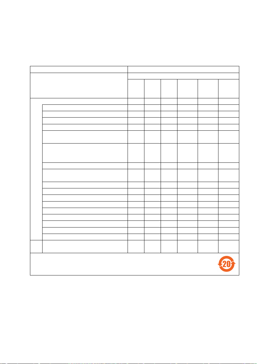
产品中有害物质的名称及含量
机器人型号名称
LS-B系列
部件名称
有害物质
铅 汞 镉
六价铬
多溴
联苯
多溴
二苯醚
(Pb)
(Hg)
(Cd)
(Cr(VI))
(PBB)
(PBDE)
机器人
电机 (执行器单元、电机单元)
减速机单元
电磁制动器
同步皮带
电池单元
(电池、电池固定架、电池基板)
密封
(密封填料、油封、密封脂、垫片、
O型环)
润滑脂
电缆
(M/C电缆、连接电缆)
散热片
LED指示灯
电路板
外罩
滚珠丝杠花键
制动解除开关
伸缩罩
扎带
气管接头
选
件
相机安装板
产品环保使用期限的使用条件
附注:
Note:
China RoHS
This sheet and environmental protection use period label are based on the regulation
in China. These are not necessary to be concerned in other countries.
× ○ ○ ○ ○ ○
× ○ ○ ○ ○ ○
× ○ ○ ○ ○ ○
× ○ ○ ○ ○ ○
○ ○ ○ ○ ○ ○
× ○ ○ ○ ○ ○
× ○ ○ ○ ○ ○
○ ○ ○ ○ ○ ○
× ○ ○ ○ ○ ○
○ ○ ○ ○ ○ ○
○ ○ ○ ○ ○ ○
× ○ ○ ○ ○ ○
○ ○ ○ ○ ○ ○
○ ○ ○ ○ ○ ○
× ○ ○ ○ ○ ○
○ ○ ○ ○ ○ ○
○ ○ ○ ○ ○ ○
× ○ ○ ○ ○ ○
× ○ ○ ○ ○ ○
本表格依据SJ/T 11364的规定编制。
○:表示该有害物质在该部件所有均质材料中的含量在GB/T 26572规定的限量要求以下。
×:表示该有害物质至少在该部件的某一均质材料中的含量超出GB/T 26572规定的限量要求。
本产品中含有的有害物质的部件皆因全球技术发展水平限制而无法实现有害物质的替代。
关于适用于在中华人民共和国境内销售的电器电子产品的环保使用期限,在遵守该产品的安全及使用注意
事项的条件下,从生产日期开始计算,在标志的年限内,本产品中含有的有害物质不会对环境造成严重污
染或对人身、财产造成严重损害。
本表格及环保使用期限标志依据中国的有关规定而制定,中国以外的国家/地区则无需关注。
This sheet and environmental protection use period label are based on the regulation
in China. These are not necessary to be concerned in other countries.
Safety and Installation (RC90-B / EPSON RC+ 7.0) Rev.4 ix
Page 12
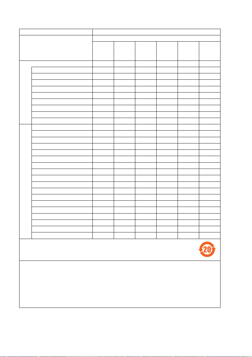
产品中有害物质的名称及含量
控制器型号名称
RC90-B系列
部件名称
有害物质
铅 汞 镉
六价铬
多溴
联苯
多溴
二苯醚
(Pb)
(Hg)
(Cd)
(Cr(VI))
(PBB)
(PBDE)
控制器
机壳
电路板
开关电源
风扇
线束
电源保护装置
存储卡
电池
连接器附件
选
件
电路板
接线
接线端子
紧急停止开关
TP1
TP2
墙面安装金属件
CK1
CV1
CV2
相机
延长管
GigE相机PoE转换器
GigE相机PoE交换集线器
GigE相机三脚架适配器
以太网交换机
USB选件密钥
VRT
产品环保使用期限的使用条件
附注:
Note:
× ○ ○ ○ ○ ○
○ ○ ○ ○ ○ ○
× ○ ○ ○ ○ ○
× ○ ○ ○ ○ ○
× ○ ○ ○ ○ ○
× ○ ○ ○ ○ ○
× ○ ○ ○ ○ ○
× ○ ○ ○ ○ ○
○ ○ ○ ○ ○ ○
× ○ ○ ○ ○ ○
× ○ ○ ○ ○ ○
× ○ ○ ○ ○ ○
× ○ ○ ○ ○ ○
× ○ ○ ○ ○ ○
× ○ ○ ○ ○ ○
× ○ ○ ○ ○ ○
× ○ ○ ○ ○ ○
× ○ ○ ○ ○ ○
× ○ ○ ○ ○ ○
× ○ ○ ○ ○ ○
× ○ ○ ○ ○ ○
× ○ ○ ○ ○ ○
× ○ ○ ○ ○ ○
× ○ ○ ○ ○ ○
× ○ ○ ○ ○ ○
× ○ ○ ○ ○ ○
× ○ ○ ○ ○ ○
× ○ ○ ○ ○ ○
本表格依据SJ/T 11364的规定编制。
○:表示该有害物质在该部件所有均质材料中的含量在GB/T 26572规定的限量要求以下。
×:表示该有害物质至少在该部件的某一均质材料中的含量超出GB/T 26572规定的限量要求。
本产品中含有的有害物质的部件皆因全球技术发展水平限制而无法实现有害物质的替代。
关于适用于在中华人民共和国境内销售的电器电子产品的环保使用期限,在遵守该产品的安全及使用注
意事项的条件下,从生产日期开始计算,在标志的年限内,本产品中含有的有害物质不会对环境造成严
重污染或对人身、财产造成严重损害。
本表格及环保使用期限标志依据中国的有关规定而制定,中国以外的国家/地区则无需关注。
This sheet and environmental protection use period label are based on the regulation
in China. These are not necessary to be concerned in other countries.
x Safety and Installation (RC90-B / EPSON RC+ 7.0) Rev.4
Page 13

Table of Contents
1. Safety 1
1.1 Conventions .............................................................................. 1
1.2 Design and Installation Safety ................................................... 2
1.3 Operation Safety ....................................................................... 7
1.4 Maintenance Safety ................................................................. 16
1.5 Emergency Stop ...................................................................... 19
1.6 Labels ...................................................................................... 24
1.7 Safety Features ....................................................................... 31
1.8 Lockout / Tagout ...................................................................... 34
1.9 Manipulator Specifications ...................................................... 36
1.10 Motion Range Setting by Mechanical Stops .......................... 43
1.11 End User Training .................................................................. 44
2. Installation 45
System Example .............................................................................. 46
2.1 Outline from Unpacking to Operation of Robot System ........... 47
2.2 Unpacking ............................................................................... 48
2.3 Transportation ......................................................................... 49
2.4 Manipulator Installation ........................................................... 51
2.5 Controller Installation ............................................................... 58
1.2.1 Relevant Manuals .......................................................... 2
1.2.2 Designing a Safe Robot System .................................... 3
1.3.1 Safety-related Requirements ....................................... 10
1.3.2 Part Names / Arm Motion .............................................. 11
1.3.3 Operation Modes ......................................................... 15
1.5.1 Free running distance in emergency ............................ 19
1.5.2 How to Reset the Emergency Mode ............................ 24
1.6.1 Controller ..................................................................... 25
1.6.2 Manipulator .................................................................. 26
Installing the Lockout Attachment ............................................ 34
Padlock Size and Weight ........................................................ 35
Safety Precautions .................................................................. 35
2.3.1 Transportation Precautions .......................................... 49
2.3.2 Manipulator Transportation .......................................... 50
2.4.1 Installation Precautions ................................................ 51
2.4.2 Environment................................................................. 52
2.4.3 Noise level ................................................................... 53
2.4.4 Base Table ................................................................... 54
2.4.5 Installation Procedure .................................................. 55
2.5.1 Installation Precautions ................................................ 58
2.5.2 Environment................................................................. 59
Safety and Installation (RC90-B / EPSON RC+ 7.0) Rev.4 xi
Page 14

2.5.3 Installation ................................................................... 60
2.6 Connection to EMERGENCY Connector (Controller) .............. 62
2.6.1 Safety Door Switch and Latch Release Switch ............ 62
2.6.2 Safety Door Switch ...................................................... 63
2.6.3 Latch Release Switch .................................................. 64
2.6.4 Checking Latch Release Switch Operation .................. 65
2.6.5 Emergency Stop Switch ............................................... 65
2.6.6 Checking Emergency Stop Switch Operation .............. 66
2.6.7 Pin Assignments .......................................................... 67
2.6.8 Circuit Diagrams .......................................................... 68
2.7 Power Source .......................................................................... 70
2.7.1 Power Supply .............................................................. 70
2.7.2 AC Power Cable .......................................................... 71
2.7.3 M/C Power Cable Connection ..................................... 72
2.8 Connecting Manipulator and Controller ................................... 73
2.9 Power-on ................................................................................. 74
2.9.1 Power-on Precautions ................................................. 74
2.9.2 Power ON Procedure ................................................... 75
2.10 Saving Default Status ............................................................ 75
3. First Step 76
3.1 Installing EPSON RC+ 7.0 Software ....................................... 76
3.2 Development PC and Controller Connection ........................... 79
3.2.1 About Development PC Connection Port ..................... 79
3.2.2 Precaution ................................................................... 80
3.2.3 Software Setup and Connection Check ....................... 80
3.2.4 Backup the initial condition of the Controller ................ 81
3.2.5 Disconnection of Development PC and Controller ....... 82
3.2.6 Moving the Robot to Initial Position.............................. 82
3.3 Writing your first program ........................................................ 86
4. Second Step 93
4.1 Connection with External Equipment....................................... 93
4.1.1 Remote Control............................................................ 93
4.1.2 Ethernet ....................................................................... 93
4.1.3 RS-232C (Option) ........................................................ 93
4.1.4 Analog I/O (Option) ...................................................... 93
4.2 Ethernet Connection of Development PC and Controller ........ 94
4.3 Connection of Option Teaching Pendant ................................. 94
Table of Contents
xii Safety and Installation (RC90-B / EPSON RC+ 7.0) Rev.4
Page 15

Table of Contents
5. General Maintenance 95
5.1 Schedule for Maintenance Inspection ..................................... 95
5.1.1 Manipulator .................................................................. 95
5.1.2 Controller ..................................................................... 98
5.2 Overhaul (Parts Replacement) ................................................ 99
5.3 Tightening Hexagon Socket Head Cap Bolts ........................ 101
5.4 Greasing ................................................................................ 102
5.5 Handling and Disposal of Batteries ....................................... 104
6. Manuals 106
Software ......................................................................................... 106
Software Options ........................................................................... 106
Controller ....................................................................................... 107
Controller Options .......................................................................... 107
Manipulator .................................................................................... 107
7. Directives and Norms 108
Safety and Installation (RC90-B / EPSON RC+ 7.0) Rev.4 xiii
Page 16

Table of Contents
xiv Safety and Installation (RC90-B / EPSON RC+ 7.0) Rev.4
Page 17
1. Safety
or death exists if the associated instructions are not followed
This symbol indicates that a danger of possible harm to
Installation and transportation of robots and robotic equipment shall be performed
by qualified personnel and should conform to all national and local codes.
Please read this manual and other related manuals before installing the robot
system or before connecting cables.
Keep this manual handy for easy access at all times.
1.1 Conventions
Important safety considerations are indicated throughout the manual by the
following symbols. Be sure to read the descriptions shown with each symbol.
This symbol indicates that a danger of possible serious injury
WARNING
WARNING
CAUTION
properly.
This symbol indicates that a danger of possible harm to
people caused by electric shock exists if the associated
instructions are not followed properly.
people or physical damage to equipment and facilities exists
if the associated instructions are not followed properly.
1. Safety
Safety and Installation (RC90-B / EPSON RC+ 7.0) Rev.4 1
Page 18
1. Safety
Personnel who
must read the
the safety requirements before designing and/or constructing the robot
system. Designing and/or constructing the robot system without
understanding the safety requirements is extremely hazardous, and may
result in serious bodily injury and/
system.
The Manipulator and the Controller must be used within the environmental
conditions described in their respective manuals. This product has been
designed and manufactured strictly for use in a normal
Using the product in an environment that exceeds the specified
environmental conditions may not only shorten the life cycle of the product
but may also cause serious safety problems.
The robot system must be used within the
in the manuals. Using the robot system outside of the installation
requirements may not only shorten the life cycle of the product but also
cause serious safety problems.
Controller manual : Setup & Operation 3. Installation
1.2 Design and Installation Safety
Only trained personnel should design and install the robot system. Trained
personnel are defined as those who have taken robot system training held by the
manufacturer, dealer, or local representative company, or those who understand the
manuals thoroughly and have the same knowledge and skill level as those who
have completed the training courses.
To ensure safety, a safeguard must be installed for the robot system. For details
on the safeguard, refer to the Installation and Design Precautions in the Safety
chapter of the EPSON RC+ User’s Guide.
The following items are safety precautions for design personnel:
■
■
WARNING
2 Safety and Installation (RC90-B / EPSON RC+ 7.0) Rev.4
■
Further precautions for installation are mentioned in the following manuals.
Please read this chapter carefully to understand safe installation procedures before
installing the robots and robotic equipment.
Refer
1.2.1 Relevant Manuals
This manual : 2. Installation
Manipulator manual : Setup & Operation 3. Environment and Installation
design and/or construct the robot system with this product
Safety chapter in the EPSON RC+ User’s Guide to understand
or severe equipment damage to the robot
indoor environment.
installation requirements described
Page 19

1. Safety
1.2.2 Designing a Safe Robot System
It is important to operate robots safely. It is also important for robot users to give
careful consideration to the safety of the overall robot system design.
This section summarizes the minimum conditions that should be observed when
using EPSON robots in your robot systems.
Please design and manufacture robot systems in accordance with the principles
described in this and the following sections.
Environmental Conditions
Carefully observe the conditions for installing robots and robot systems that are
listed in the “Environmental Conditions” tables included in the manuals for all
equipment used in the system.
System Layout
When designing the layout for a robot system, carefully consider the possibility of
error between robots and peripheral equipment. Emergency stops require
particular attention, since a robot will stop after following a path that is different
from its normal movement path. The layout design should provide enough
margins for safety. Refer to the manuals for each manipulator, and ensure that
the layout secures ample space for maintenance and inspection work.
When designing a robot system to restrict the area of motion of the robots, do so in
accordance with the methods described in each manipulator manual. Utilize both
software and mechanical stops as measures to restrict motion.
Install the emergency stop switch at a location near the operation unit for the robot
system where the operator can easily press and hold it in an emergency.
Do not install the controller at a location where water or other liquids can leak
inside the controller. In addition, never use liquids to clean the controller.
Disabling Power to the System using lock out / tag out
The power connection for the robot controller should be such that it can be locked
and tagged in the off position to prevent anyone from turning on power while
someone else is in the safeguarded area.
For further details, refer to the following section:
1.8 Lockout/Tagout
Safety and Installation (RC90-B / EPSON RC+ 7.0) Rev.4 3
Page 20

1. Safety
End Effector Design
Provide wiring and piping that will prevent the robot end effector from releasing
the object held (the work piece) when the robot system power is shut off.
Design the robot end effector such that its weight and moment of inertia do not
exceed the allowable limits. Use of values that exceed the allowable limits can
subject the robot to excessive loads. This will not only shorten the service life of
the robot but can lead to unexpectedly dangerous situations due to additional
external forces applied to the end effector and the work piece.
Design the size of the end effector with care, since the robot body and robot end
effector can interfere with each other.
Peripheral Equipment Design
When designing equipment that removes and supplies parts and materials to the
robot system, ensure that the design provides the operator with sufficient safety.
If there is a need to remove and supply materials without stopping the robot, install
a shuttle device or take other measures to ensure that the operator does not need to
enter a potentially dangerous zone.
Ensure that an interruption to the power supply (power shutoff) of peripheral
equipment does not lead to a dangerous situation. Take measures that not only
prevent a work piece held from being released as mentioned in “End effector
Design” but that also ensure peripheral equipment other than the robots can stop
safely. Verify equipment safety to ensure that, when the power shuts off, the area
is safe.
Remote Control
To prevent operation by remote control from being dangerous, start signals from
the remote controller are allowed only when the control device is set to REMOTE,
TEACH mode is OFF, and the system is configured to accept remote signals.
Also when remote is valid, motion command execution and I/O output are
available only from remote. For the safety of the overall system, however, safety
measures are needed to eliminate the risks associated with the start-up and
shutdown of peripheral equipment by remote control.
Emergency Stop
Each robot system needs equipment that will allow the operator to immediately
stop the system’s operation. Install an emergency stop device that utilizes
emergency stop input from the controller and all other equipment.
During the emergency stop, the power supplied to the motor for driving the robot
is shut off, and the robot is stopped due to the dynamic brake.
4 Safety and Installation (RC90-B / EPSON RC+ 7.0) Rev.4
Page 21

1. Safety
Make sure that all external components that shut off the power in case of
emergency are turned OFF by the emergency stop circuit. Do not design to turn
OFF the robot controller by using outputs of all I/O boards. For example, if the
I/O board is faulty, the controller cannot turn OFF the power of external
components. The emergency stop on the controller is hardwired to disconnect the
motor power from the robot, but not the external power supplies.
For details of the Safeguard system, refer to the following section.
1.5 Emergency Stop
Safeguard System
To ensure safety, a safeguard system should be installed for the robot system.
When installing the safeguard system, strictly observe the following points:
Refer to each robot manual, and install the safeguard system outside the maximum
space. Carefully consider the size of the end effector and the work pieces to be
held so that there will be no error between the moving parts and the safeguard
system.
Manufacture the safeguard system to withstand calculated external forces (forces
that will be added during operation and forces from the surrounding environment).
When designing the safeguard system, make sure that it is free from sharp corners
and projections, and that the safeguard system itself is not dangerous.
Make sure that the safeguard system can only be removed by using a tool.
There are several types of safeguard devices, including safety doors, safety
barriers, light curtains, safety gates, and safety floor mats. Install the interlocking
function in the safeguard device. The safeguard interlock must be installed so
that the safeguard interlock is forced to work in case of a device failure or other
unexpected accident. For example, when using a door with a switch as the
interlock, do not rely on the switch’s own spring force to open the contact. The
contact mechanism must open immediately in case of an accident.
Connect the interlock switch to the safeguard input of the drive unit’s
EMERGENCY connector. The safeguard input informs the robot controller that
an operator may be inside the safeguard area. When the safeguard input is
activated, the robot stops immediately and enters pause status, as well as either
operation-prohibited status or restricted status (low power status).
Make sure not to enter the safeguarded area except through the point where the
safeguard interlock is installed.
Safety and Installation (RC90-B / EPSON RC+ 7.0) Rev.4 5
Page 22

1. Safety
The safeguard interlock must be installed so that it can maintain a safe condition
until the interlock is released on purpose once it initiates. The latch-release input
is provided for the EMERGENCY connector on the Controller to release the latch
condition of the safeguard interlock. The latch release switch of the safeguard
interlock must be installed outside of the safeguarded area and wired to the
latch-release input.
It is dangerous to allow someone else to release the safeguard interlock by mistake
while the operator is working inside the safeguarded area. To protect the operator
working inside the safeguarded area, take measures to lock out and tag out the
latch-release switch.
Presence Sensing Device
The above mentioned safeguard interlock is a type of presence sensing device
since it indicates the possibility of somebody being inside the safeguard system.
When separately installing a presence sensing device, however, perform a
satisfactory risk assessment and pay thorough attention to its dependability.
Here are precautions that should be noted:
- Design the system so that when the presence sensing device is not
activated or a dangerous situation still exists that no personnel can go
inside the safeguard area or place their hands inside it.
- Design the presence sensing device so that regardless of the situation the
system operates safely.
- If the robot stops operating when the presence sensing device is activated,
it is necessary to ensure that it does not start again until the detected
object has been removed. Make sure that the robot cannot
automatically restart.
Resetting the Safeguard
Ensure that the robot system can only be restarted through careful operation from
outside the safeguarded system. The robot will never restart simply by resetting
the safeguard interlock switch. Apply this concept to the interlock gates and
presence sensing devices for the entire system.
Robot Operation Panel
When using the robot operation panel, it must be installed so as to operate the
robot system from outside the safeguard.
6 Safety and Installation (RC90-B / EPSON RC+ 7.0) Rev.4
Page 23
1.3 Operation Safety
Please carefully read the Safety-related Requirements before
operating the robot system.
the robot system without
understanding the safety requirements is extremely hazardous and
may result in serious bodily injury and/or sever
the robot system.
Do not enter the operating area of the Manipulator while the power to
the robot system is turned ON.
power ON is extremely hazardous and may cause serious safety
problems as the Manipulator may move even if it seems to
Before operating the robot system, make sure that no one is inside the
safeguarded area.
teaching
The motion of the Manipulator is always in restricted
and low power) to secure the safety of an operator.
operating the robot system while someone is inside the safeguarded
area is extremely hazardous and may result in serious s
in case that the Manipulator moves unexpectedly.
Immediately press the Emergency Stop switch whenever the
Manipul
Continuing operation of the robot system while the Manipulator mo
abnormally is extremely hazardous and may result in serious bodily
injury and/or severe equipment change to the robot system.
To shut off power
the power source. Be sure to connect the AC power cable to a power
receptacle.
DO NOT connect it directly to a factory power source.
The following items are safety precautions for qualified Operator personnel:
■
■
■
WARNING
1. Safety
Operating
e equipment damage to
Entering the operating area with the
be stopped.
The robot system can be operated in the mode for
even when someone is inside the safeguarded area.
status (low speed
However,
■
ator moves abnormally while the robot system is operated.
WARNING
Safety and Installation (RC90-B / EPSON RC+ 7.0) Rev.4 7
■
to the robot system, disconnect the power plug from
afety problems
ves
Page 24
1. Safety
Before
C
from the power source.
Performing any replacement procedure with the power ON is
extremely hazardous and may result in electric shock and/or
malfunction of the robot system.
Do not connect or disconnect the motor connectors while the power to
the robot system is turned ON. Connecting or disconnecting the
motor connectors
result
abnormally, and also may result in
the robot system.
Whenever possible, only one person should operate the robot system.
If it is necessary to operate the robot system with more than one
person, ensure that all people involved communicate with each other
as to what they are doing and take all necessary safety precautions.
Joint #1, #2, and #4:
If the joints are operated
5 degrees, they may get damaged early because the bearings are
likely to cause oil film shortage in such situation. To prevent early
breakdown, move the joints larger than 50 degrees
ten times a day.
Joint #3:
If the up
a half of the maximum stroke for five to ten times a day.
LS20-B : less than 50 mm
WARNING
■
■
■
performing any replacement procedure, turn OFF the
ontroller and related equipment, and then disconnect the power plug
with the power ON is extremely hazardous and may
in serious bodily injury as the Manipulator may move
electric shock and/or malfunction of
■
CAUTION
8 Safety and Installation (RC90-B / EPSON RC+ 7.0) Rev.4
-and-down motion of the hand is the following, move the joint
LS3-B : less than 32 mm
LS6-B : less than 40 mm
LS10-B : less than 50 mm
repeatedly with the operating angle less than
for about five to
Page 25
■
Oscillation (resonance) may occur continuously depending on the
combination of robot motion speed, Arm orientation, and end effector
load.
and can be
Manipulator may be warmed up due to motor heat or similar causes.
Do not touch the Manipulator
the temperature of the Manipulator falls and
it.
Oscillation arises from natural oscillation frequency of the Arm
controlled by following measures.
Changing Manipulator speed
CAUTION
Changing the teach points
Changing the end effector load
■
Then perform teaching or maintenance.
1. Safety
until temperature falls. Also, make sure
is not hot when you touch
Safety and Installation (RC90-B / EPSON RC+ 7.0) Rev.4 9
Page 26

1. Safety
EN ISO 10218-1
Robots and robotic devices -- Safety requirements for industrial
EN ISO 10218-2
Robots and robotic devices -- Safety requirements for industrial
ANSI/RIA R15.06
American National Standard for Industrial Robots and Robot
EN ISO 12100
Safety of machinery -- General principles for design -- Risk
EN ISO 13849-1
Safety of machinery -- Safety-related parts of control systems --
EN ISO 13850
Safety of machinery -- Emergency stop function-- Principles for
Safety of machinery -- Positioning of safeguards with respect to the
Safety of machinery -- Safety distances to prevent hazard zones
EN ISO14120
Safety of machinery -- Guards -- General requirements for the
IEC 60204-1
Safety of machinery -- Electrical equipment of machines -- Part 1:
CISPR11
Industrial, scientific and medical (ISM) radio-frequency equipment
Limits and
IEC 61000-6-2
Electromagnetic compatibility (EMC) -- Part 6-2: Generic
1.3.1 Safety-related Requirements
Specific tolerances and operating conditions for safety are contained in the
manuals for the robot, controller and other devices. Be sure to read those
manuals as well.
For the installation and operation of the robot system, be sure to comply with the
applicable local and national regulations.
Robot system safety standards and other examples are given in this chapter.
To ensure that safety measures are satisfied, also refer to these standards.
(Note: The following is a partial list of the necessary safety standards.)
robots -- Part 1: Robots
robots -- Part 2: Robot systems and integration
Systems -- Safety Requirements
assessment and risk reduction
Part 1: General principles for design
design
EN ISO 13855
EN ISO 13857
EN 60204-1
EN55011
EN 61000-6-2
approach speeds of parts of the human body.
being reached by upper and lower limbs.
design and construction of fixed and movable guards
General requirements
-- Electromagnetic disturbance characteristics -methods of measurement
standards -- Immunity for industrial environments
10 Safety and Installation (RC90-B / EPSON RC+ 7.0) Rev.4
Page 27
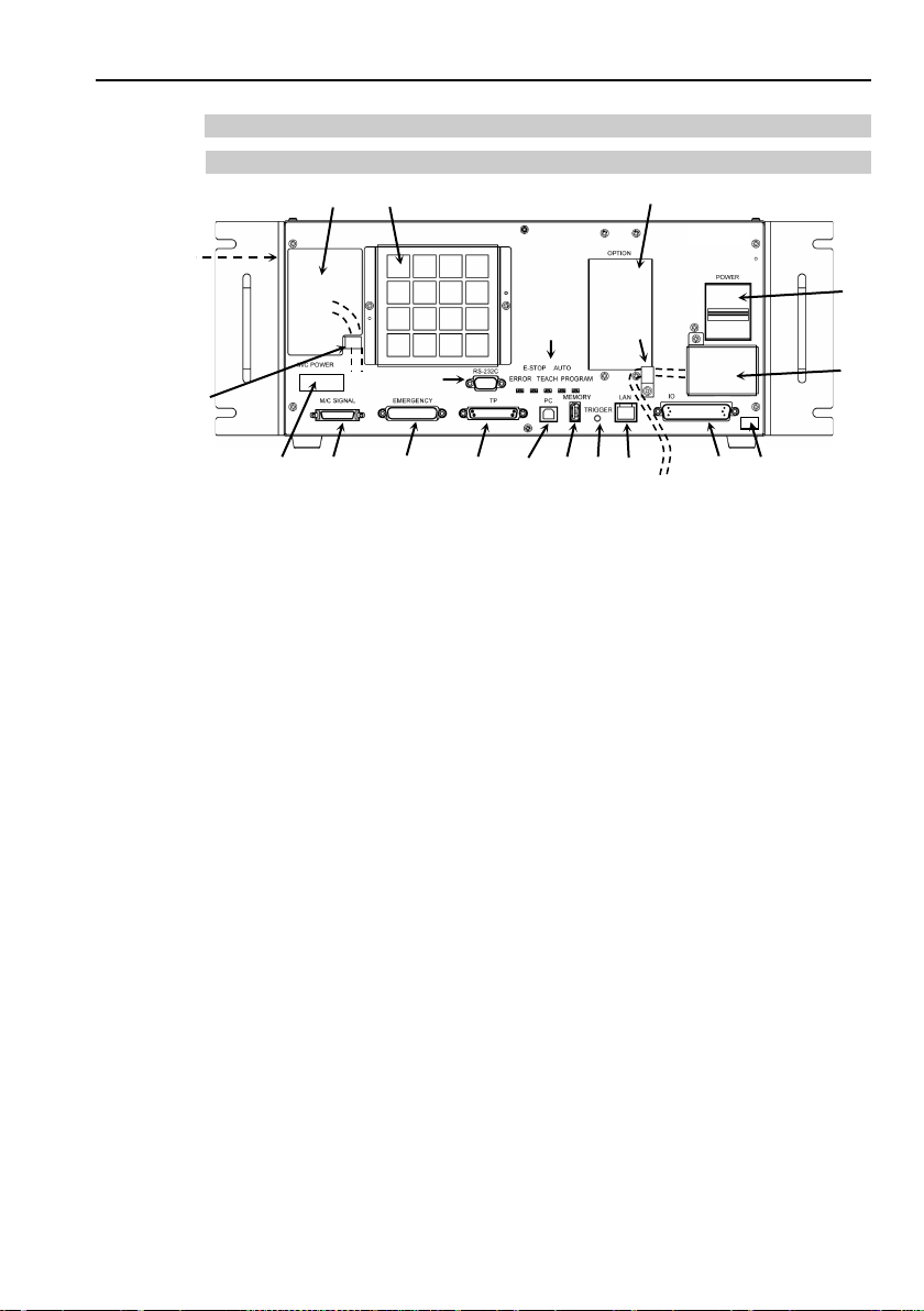
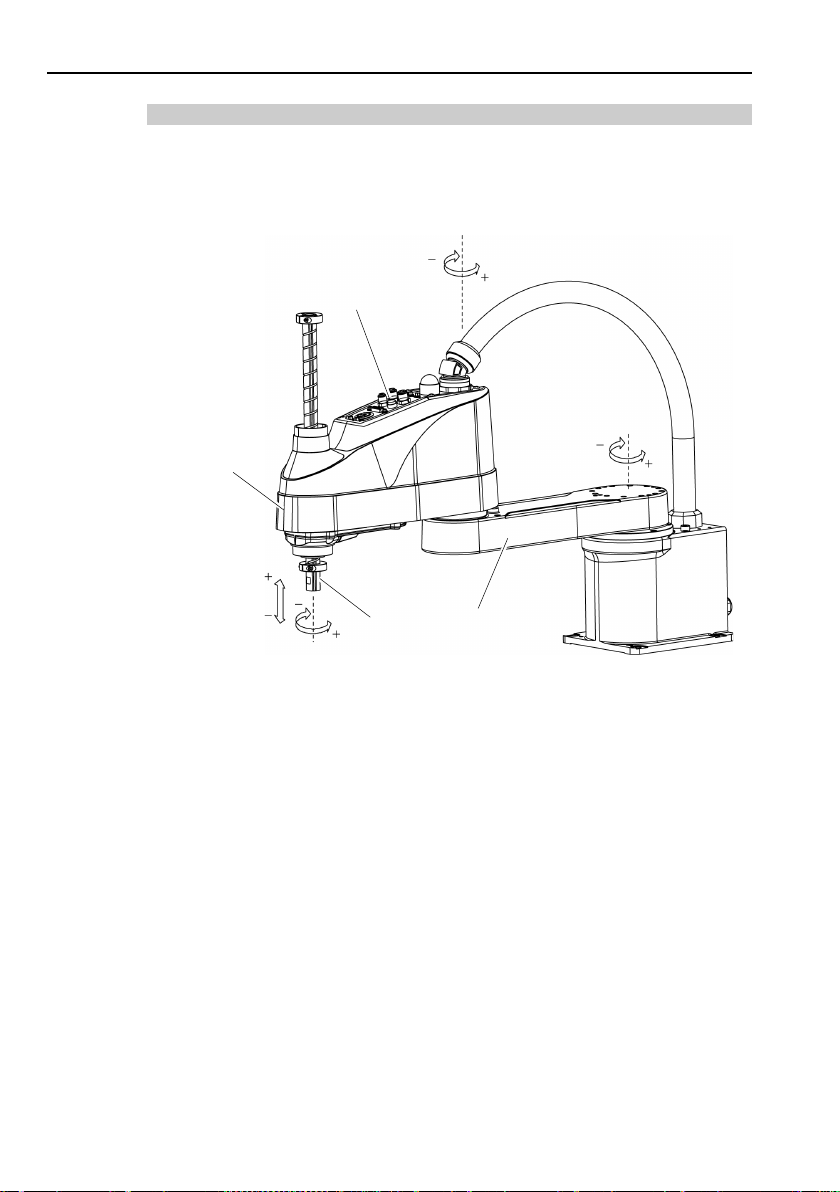
1.3.2 Part Names / Arm Motion
(3)
(18)
(11) (12) (13) (14) (15) (16) (6)
(4)
(1)
(10)
(9)
(8)
(19)
(19)
(17)
(5)
(Left side)
(2)
(7)
(10) EMERGENCY connector
(20) Battery (Mounted inside the controller)
RC90-B
(1)
POWER switch
(2) AC IN
(3) LED
(4) Fan Filter
(5) Signature label
(6) Controller Number label
(7) Connection Check label
(8) M/C POWER connector
(9) M/C SIGNAL connector
1. Safety
(11) TP port
(12) Development PC connection port
(13) Memory port
(14) Trigger Switch
(15) LAN (Ethernet communication) port
(16) I/O connector
(17) Standard RS-232C port
(18) Option slot
(19) Cable Clamp
Safety and Installation (RC90-B / EPSON RC+ 7.0) Rev.4 11
Page 28
1. Safety
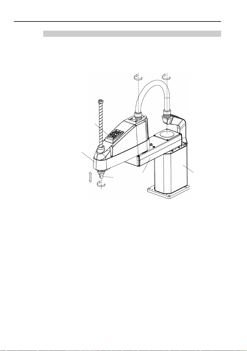
Brake release switch
Joint #1
(Rotation)
Joint #2
(Rotation)
Joint #3
(Up/Down)
Joint #4
(Rotation)
Arm #1
Arm #2
+
−
+
−
+ − +
−
Shaft
(Figure: LS20-B804S)
Base
NOTE
LS20-B
The motion range of each arm is shown in the figure below. Take all
necessary safety precautions.
When the system is placed in emergency mode, push the arm or joint of the
Manipulator by hand as shown below:
Arm #1 Push the arm by hand.
Arm #2 Push the arm by hand.
Joint #3 The joint cannot be moved up/down by hand until the
electromagnetic brake applied to the joint has been released.
Move the joint up/down while pressing the brake release switch.
Joint #4 The shaft cannot be rotated by hand until the electromagnetic
brake applied to the shaft has been released. Move the shaft
while pressing the brake release switch.
The brake release switch affects both Joints #3 and #4. When the brake
release switch is pressed in emergency mode, the brakes for both Joints #3
and #4 are released simultaneously. Be careful of the shaft falling and
rotating while the brake release switch is pressed because the shaft may be
lowered by the weight of an end effector.
12 Safety and Installation (RC90-B / EPSON RC+ 7.0) Rev.4
Page 29
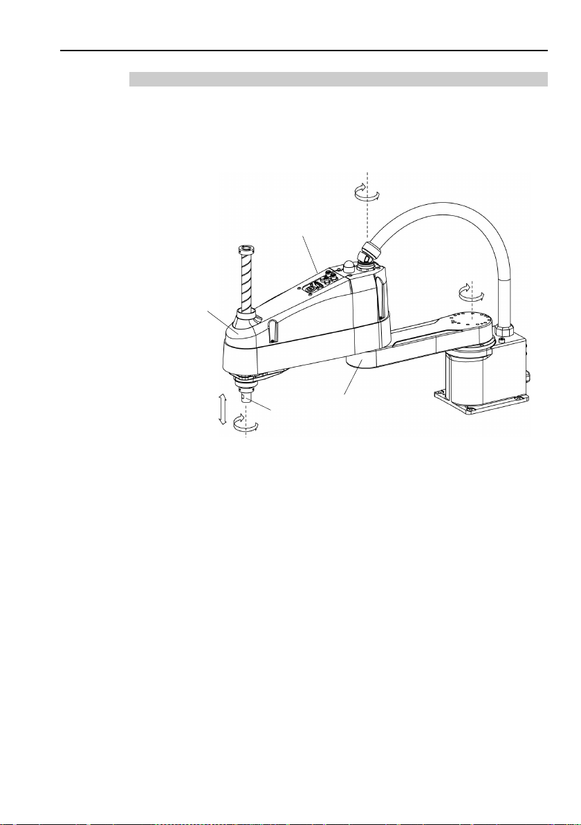
LS10-B
Joint #3, #4
Brake release switch
Joint #1
(Rotation)
Joint #2
(Rotation)
Joint #3
(Up/Down)
Joint #4
(Rotation)
Arm #1
Arm #2
+
−
+
−
+
−
+
−
Shaft
(Figure: LS10-B702S)
NOTE
The motion range of each arm is shown in the figure below. Take all
necessary safety precautions.
1. Safety
Safety and Installation (RC90-B / EPSON RC+ 7.0) Rev.4 13
When the system is placed in emergency mode, push the arm or joint of the
Manipulator by hand as shown below:
Arm #1 Push the arm by hand.
Arm #2 Push the arm by hand.
Joint #3 The joint cannot be moved up/down by hand until the
Joint #4 The shaft cannot be rotated by hand until the electromagnetic
The brake release switch affects both Joints #3 and #4. When the brake
release switch is pressed in emergency mode, the brakes for both Joints #3
and #4 are released simultaneously. Be careful of the shaft falling and
rotating while the brake release switch is pressed because the shaft may be
lowered by the weight of an end effector.
electromagnetic brake applied to the joint has been released.
Move the joint up/down while pressing the brake release switch.
brake applied to the shaft has been released. Move the shaft
while pressing the brake release switch.
Page 30
1. Safety
Brake release switch
Joint #1
(Rotation)
Joint #2
(Rotation)
Joint #4
(Rotation)
Joint #3
(Up/Down)
Arm #1
Arm #2
Shaft
(Figure: LS6-B602S)
LS3-B, LS6-B
The motion range of each arm is shown in the figure below. Take all
necessary safety precautions.
When the system is placed in emergency mode, push the arm or joint of the
Manipulator by hand as shown below:
Arm #1 Push the arm by hand.
Arm #2 Push the arm by hand.
Joint #3 The joint cannot be moved up/down by hand until the
electromagnetic brake applied to the joint has been released.
Move the joint up/down while pressing the brake release switch.
Joint #4 LS3-B Rotate the shaft by hand.
LS6-B The shaft cannot be rotated by hand until the
electromagnetic brake applied to the shaft has been
released. Move the shaft while pressing the brake
release switch.
14 Safety and Installation (RC90-B / EPSON RC+ 7.0) Rev.4
Page 31

LS3-B: The brake release switch is applied to Joint #3. When the brake release
NOTE
switch is pressed in emergency mode, the brake for Joint #3 is released.
Be careful of the shaft falling while the brake release switch is pressed
because the shaft may be lowered by the weight of an end effector.
LS6-B: The brake release switch is applied to both Joint #3 and Joint #4. When
the brake release switch is pressed in emergency mode, the brakes for both
Joints #3 and #4 are released simultaneously. Be careful of the shaft
falling and rotating while the brake release switch is pressed because the
shaft may be lowered by the weight of an end effector.
1.3.3 Operation Modes
The operation mode is defined as the single control point for the controller, therefore
you cannot use more than one operation mode at the same time.
There are four operation modes for the controller: AUTO, PROGRAM, TEACH, and
TEST.
- AUTO operation modes allow you to execute programs in the controller when
the safeguard is closed.
- PROGRAM operation mode allows you to execute and debug programs when
the safeguard is closed.
- TEACH operation mode allows you to jog and teach the robot at slow speed
while inside the safeguarded area.
- TEST operation mode allows you to execute a program at slow speed while the
safeguard is opened.
1. Safety
Safety and Installation (RC90-B / EPSON RC+ 7.0) Rev.4 15
Page 32

1. Safety
Do not remove any parts that are not covered in th
the maintenance procedure strictly as described in this manual
Maintenance
Controller manual
maintenance may not only cause improper function of the robot sy
but also serious safety problems.
Keep away from the Manipulator while
taken the training courses.
power
extremely
Manipulator may move
When you check the operation of the Manipulator a
be sure to
Checking the operation of the Manipulator while you are inside of the
safeguarded area may cause serious safety problems as the
Manipulator may move unexpectedly.
Before
S
the robot system when the switches do not function properly is
extremely hazardous and may result in serious bodily injury and/or
serious damage
inten
1.4 Maintenance Safety
Please read this section, Maintenance of the Manipulator manual, Maintenance of
the Controller manual, and other related manuals carefully to understand safe
maintenance procedures before performing any maintenance.
Only authorized personnel who have taken the safety training should be allowed to
maintain the robot system. The safety training is the program for the industrial
robot operator that follows the laws and regulations of each nation.
The personnel who have taken the safety training acquire knowledge of industrial
robots (operations, teaching, etc.), knowledge of inspections, and knowledge of
related rules/regulations. Only personnel who have completed the robot
system-training and maintenance-training classes held by the manufacturer, dealer,
or locally-incorporated company should be allowed to maintain the robot system.
WARNING
■
of the Manipulator manual, and Maintenance of the
. Improper removal of parts or improper
■
Do not enter the operating area while the
is ON. Entering the operating area with the power ON is
hazardous and may cause serious safety problems as the
even though it seems to be stopped.
■
check it while you are outside of the safeguarded area.
■
operating the robot system, make sure that both the Emergency
top switches and safeguard switches function properly. Operating
the power is ON if you have not
is manual. Follow
fter replacing parts,
,
stem
16 Safety and Installation (RC90-B / EPSON RC+ 7.0) Rev.4
ded functions in an emergency.
to the robot system as the switches cannot fulfill their
Page 33

■
Be sure to connect the AC power cable to a power receptacle. DO
NOT connect it directly to a factory power source. To shut off power
the
the power plug from the power source.
Performing any work while connecting the AC power cable to a factory
power source is extremely hazardous and may result in
and/or malfunction of the robot system.
Before
and related equipment,
power source.
Performing any replacement procedure with the power ON is extremely
hazardous and may result in
robot system.
Be sure to connect the cables properly.
strain on the cables.
bend or pull the cables forcibly.)
may result in damage to the cables, disconnection, and/or contact
failure.
hazardous and may result in electric shock and/or improper function of
the robot system.
Carefully use
instructions
gasket, or adhesive may cause a fire and/or safety problems.
Wear protective gear including a mask, protective goggles, and
robot system, disconnect
1. Safety
to
electric shock
■
WARNING
■
performing any replacement procedure, turn OFF the Controller
and then disconnect the power plug from the
electric shock and/or malfunction of the
Do not allow unnecessary
(Do not put heavy objects on the cables. Do not
The unnecessary strain on the cables
Damaged cables, disconnection, or contact failure is extremely
■
- Never put alcohol, liquid gasket, or adhesive close to fire.
CAUTION
Safety and Installation (RC90-B / EPSON RC+ 7.0) Rev.4 17
- Use alcohol, liquid gasket, or adhesive while ventilating the room.
-
oil-resistant gloves.
- If alcohol, liquid gasket, or adhesive gets on your skin, wash the area
thoroughly with soap and water.
- If alcohol, liquid gasket, or adhesive gets into your eyes or mouth,
flush your eyes or wash out your mouth with clean water thoroughly,
and then see a doctor immediately.
alcohol, liquid gasket, and adhesive following respective
and also instructions below. Careless use of alcohol, liquid
Page 34

1. Safety
Wear protective gear including a mask, protective goggles, and
oil
mouth, or on your skin, follow the instructions below.
Manipulator may be warmed up due to motor heat or similar causes.
Do not touch the Manipulator
the temperature of the Manipulator falls and you
you touch it.
■
-resistant gloves during grease up. If grease gets into your eyes,
If grease gets into your eyes:
Flush them thoroughly with clean water, and then see a doctor
immediately.
If grease gets into your mouth:
If swallowed, do not induce vomiting. See a doctor immediately.
CAUTION
■
If grease just gets into your mouth, wash out your mouth with
water thoroughly.
If grease gets on your skin:
Wash the area thoroughly with soap and water.
Then perform teaching or maintenance.
until temperature falls. Also, make sure
do not feel hot when
18 Safety and Installation (RC90-B / EPSON RC+ 7.0) Rev.4
Page 35

1.5 Emergency Stop
1.5.1 Free running distance in emergency
If the Manipulator moves abnormally during operation, immediately press the
Emergency Stop switch. The motor power will be turned OFF, and the arm
motion by inertia will be stopped with the electromagnetic brake and dynamic
brake.
However, avoid pressing the Emergency Stop switch unnecessarily while the
Manipulator is running normally. Pressing the switch during the operation makes
the brakes work. This will shorten the life of the brakes due to the worn friction
plates.
Normal brake life cycle: About 2 years (when the brakes are used 100 times/day)
To place the robot system in emergency mode during normal operation, press the
Emergency Stop switch when the Manipulator is not moving.
Refer to the Controller manual for instructions on how to wire the Emergency Stop
switch circuit.
Do not turn OFF the Controller while the Manipulator is operating.
If you attempt to stop the Manipulator in emergency situations such as “Safeguard
Open”, make sure to stop the Manipulator using the E-STOP switch of the
Controller.
If the Manipulator is stopped by turning OFF the Controller while it is operating,
following problems may occur.
Reduction of the life and damage of the reduction gear unit
Position gap at the joints
In addition, if the Controller was forced to be turned OFF by blackouts and the like
while the Manipulator is operating, make sure to check the following points after
power restoration.
Whether or not the reduction gear is damaged
Whether or not the joints are in their proper positions
If there is a position gap, perform calibration by referring to Maintenance: 13.
Calibration in the manipulator manual.
Manipulator manuals contain information on the Emergency Stop. Please also
read the descriptions in the manual and use the robot system properly.
1. Safety
Safety and Installation (RC90-B / EPSON RC+ 7.0) Rev.4 19
Page 36

1. Safety
Before using the Emergency Stop switch, be aware of the followings.
- The Emergency Stop (E-STOP) switch should be used to stop the
Manipulator only in case of emergencies.
- To stop the Manipulator operating the program except in emergency, use
Pause (halt) or STOP (program stop) commands
Pause and STOP commands do not turn OFF the motors. Therefore, the
brake does not function.
- For the Safeguard system, do not use the circuit for E-S TOP.
For details of the Safeguard system, refer to the following manuals.
EPSON RC+ User’s Guide
2. Safety - Installation and Design Precautions - Safeguard System
Safety and Installation
2.6 Connection to EMERGENCY Connector
To check brake problems, refer to the following manuals.
Manipulator Manual Maintenance
2.1.2 Inspection Point - Inspection While the Power is ON
(Manipulator is operating)
Safety and Installation
5.1.1 Manipulator - Inspection While the Power is ON
(Manipulator is operating)
20 Safety and Installation (RC90-B / EPSON RC+ 7.0) Rev.4
Page 37

1. Safety
LS20-B**4*
Accel Setting
100
Speed Setting
100
Load [kg]
20
Weight setting
20
Joint #1
Stop point
Point where the
emergency
stop signal is
input
Target point
Start point of
operation
Joint #2
Controller
RC90-B
Manipulator
LS20-B804*
LS20-BA04*
Free
time
Joint #1 + Joint #2 [s]
0.60
0.65
Free
angle
Joint #1 [deg]
65
85
Joint #2 [deg]
63
55
Joint #1 + Joint #2 [deg]
120
125
Free
distance
Free running distance
The Manipulator in operation cannot stop immediately after the Emergency Stop
switch is pressed.
The free running time/angle/distance of the Manipulator are shown below.
However, remember that the values vary depending on following conditions.
Weight of the end effector Weight Accel
Weight of work piece Speed Operating pose etc.
Approximate time and distance of the free running are as follow:
LS20-B
Conditions for Measurement
Safety and Installation (RC90-B / EPSON RC+ 7.0) Rev.4 21
running
running
running
Joint #3 [s] 0.3
Joint #3 [mm] 50
Page 38

1. Safety
LS10-B****
Accel Setting
100
Speed Setting
100
Load [kg]
10
Weight setting
10
Joint #1
Stop point
Point where the
emergency
stop signal is
input
Target point
Start point of
operation
Joint #2
Controller
RC90-B
Manipulator
LS10-B60**
LS10-B70**
LS10-B80**
Free
time
Free
angle
Joint #1 [deg]
35
75
65
Joint #2 [deg]
115
105
55
Joint #1 + Joint #2 [deg]
120
135
90
Free
distance
LS10-B
Conditions for Measurement
running
running
running
Joint #1 + Joint #2 [s] 0.7 0.9 0.7
Joint #3 [s] 0.2
Joint #3 [mm] 50
22 Safety and Installation (RC90-B / EPSON RC+ 7.0) Rev.4
Page 39

LS3-B, LS6-B
Accel Setting
100
100
Speed Setting
100
100
Load [kg]
6
3
Weight setting
6
3
Joint #1
Stop point
Point where the
emergency
stop signal is
input
Target point
Start point of
operation
Joint #2
Controller
RC90-B
Manipulator
LS6-B502*
LS6-B602*
LS6-B702*
LS3-B401*
Free
time
Joints #1+#2 [s]
0.4
0.7
0.7
0.4
Joint #1 [deg]
42
100
85
110
Joint #2 [deg]
42
45
50
20
Joints #1+#2 [deg]
84
130
135
130
Free
distance
Conditions for Measurement
LS6-B*02* LS3-B401*
1. Safety
Safety and Installation (RC90-B / EPSON RC+ 7.0) Rev.4 23
running
Free
running
angle
running
Joint #3 [s]
Joint #3 [mm]
0.2 0.1
90 20
Page 40

1. Safety
1.5.2 How to Reset the Emergency Mode
Select EPSON RC+ [Tools] – [Robot Manager] – [Control Panel] tab, and then
click <Reset>.
The Control Panel page contains buttons for basic robot operations, such as
turning motors on/off and homing the robot. It also shows status for Emergency
Stop, Safeguard, Motors, and Power.
1.6 Labels
Labels are attached around the locations of the Controller and Manipulator where
specific dangers exist.
Be sure to comply with descriptions and warnings on the labels to operate and
maintain the Robot System safely.
Do not tear, damage, or remove the labels. Use meticulous care when handling
those parts or units to which the following labels are attached as well as the nearby
areas:
24 Safety and Installation (RC90-B / EPSON RC+ 7.0) Rev.4
Page 41

1.6.1 Controller
Location
Label
Note
Residual voltage exists. To avoid
electric shock, do not open the cover
while the Power is ON, or for 300
Disconnect and lockout main power
A
D
D
C
B
D
1. Safety
A
B
C
D
seconds after the Power is OFF.
before performing maintenance and
repair.
TP port of RC90-B is for the Teach
Pendant TP1 and TP2. Do not connect
the followings to TP port of RC90.
Connecting to the followings may result in
malfunction of the device.
OPTIONAL DEVICE dummy plug,
OP500, OP500RC, JP500, TP-3** series,
and OP1
Refer to 4.3 Connection of Option
Teaching Pendant.
Hazardous voltage exists while the
Manipulator is ON. To avoid electric
shock, do not touch any internal electric
parts.
Safety and Installation (RC90-B / EPSON RC+ 7.0) Rev.4 25
Page 42

1. Safety
Location
Label
Note
osening the base mounting
screws, hold the arm and secure it
fingers from being caught in the
, follow the directions in this
the Manipulator is moving. The
robot arm may collide against the
operator. This is extremely
hazardous and may result in serious
Hazardous voltage exists while the
Manipulator is ON. To avoid electric
not touch any internal
You can catch your hand or fingers
between the shaft and cover when
bringing your hand close to moving
this label for no danger of your hand
Only authorized personnel should
work and operate a
unauthorized personnel, it is
hazardous and may result
1.6.2 Manipulator
LS20-B
Before lo
tightly with a band to prevent hands or
A
B
C
D
Manipulator.
For installation and transportation of
robots
manual.
Do not enter the operation area while
safety problems.
shock, do
electric parts.
parts.
Manipulators with bellows do not have
or fingers being caught
perform sling
crane and a forklift.
E
26 Safety and Installation (RC90-B / EPSON RC+ 7.0) Rev.4
When these operations are performed
by
extremely
in serious bodily injury and/or severe
equipment damage to the robot
system.
Page 43

1. Safety
Be careful of the shaft falling and
the brake release
Location
Signature plate
Note
rotating while
F
switch is pressed because the shaft
may be lowered by the weight of the
end effector.
G
LS20-B
Manipulator’s serial No.
(Figure: LS20-B804S)
Safety and Installation (RC90-B / EPSON RC+ 7.0) Rev.4 27
Page 44

1. Safety
Location
Label
Note
osening the base mounting
with a band to prevent hands or fingers
, follow the directions in this
may collide against the operator. This
is extremely hazardous and may result
Hazardous voltage exists while the
Manipulator is ON. To avoid electric
shock, do not touch any internal electric
You can catch your hand or fingers
between the shaft and cover when
bringing your hand close to moving
with bellows do not have
Location
Signature plate
Note
LS10-B, LS6-B, LS3-B
Before lo
screws, hold the arm and secure it tightly
A
B
C
D
from being caught in the Manipulator.
For installation and transportation of
robots
manual.
Do not enter the operation area while the
Manipulator is moving. The robot arm
in serious safety problems.
parts.
parts.
Manipulators
this label for no danger of your hand or
fingers being caught
E
Manipulator’s serial No.
28 Safety and Installation (RC90-B / EPSON RC+ 7.0) Rev.4
Page 45

LS10-B
LS6-B
1. Safety
(Figure: LS10-B702S)
(Figure: LS6-B602S)
Safety and Installation (RC90-B / EPSON RC+ 7.0) Rev.4 29
Page 46

1. Safety
LS3-B
(Figure: LS3-B401S)
30 Safety and Installation (RC90-B / EPSON RC+ 7.0) Rev.4
Page 47

1.7 Safety Features
The robot control system supports safety features described below. However, the
user is recommended to strictly follow the proper usage of the robot system by
thoroughly reading the attached manuals before using the system. Failure to read
and understand the proper usage of the safety functions is highly dangerous.
Among the following safety features, the Emergency Stop Switch and Safety Door
Input are particularly important. Make sure that these and other features function
properly before operating the robot system.
1. Safety
For details, refer to the 2.6.1 Safety Door Switch and Latch Release Switch.
Emergency Stop Switch
The EMERGENCY connector on the Controller has expansion Emergency Stop
input terminals used for connecting the Emergency Stop switches.
Pressing any Emergency Stop switch can shut off the motor power immediately
and the robot system will enter the Emergency Stop condition.
Stop category of Emergency Stop input: Category 0 (refer to Safety Standard
IEC60204-1)
Safety Door Input
In order to activate this feature, make sure that the Safety Door Input switch is
connected to the EMERGENCY connector at the Controller.
When the safety door is opened, normally the Manipulator immediately stops the
current operation, and the status of Manipulator power is operation-prohibited
until the safety door is closed and the latched condition is released. In order to
execute the Manipulator operation while the safety door is open, you must change
the mode selector key switch on the Teach Pendant to the “Teach” mode.
Manipulator operation is available only when the enable switch is on. In this
case, the Manipulator is operated in low power status.
Stop category of Safety door input: Category 1 (refer to Safety Standard
IEC60204-1)
Safety and Installation (RC90-B / EPSON RC+ 7.0) Rev.4 31
Page 48

1. Safety
Low Power Mode
The motor power is reduced in this mode.
Executing a power status change instruction will change to the restricted (low
power) status regardless of conditions of the safety door or operation mode. The
restricted (low power) status ensures the safety of the operator and reduces the
possibility of peripheral equipment destruction or damage caused by careless
operation.
Dynamic Brake
The dynamic brake circuit includes relays that short the motor armatures.
The dynamic brake circuit is activated when there is an Emergency Stop input or
when any of the following errors is detected: encoder cable disconnection, motor
overload, irregular motor torque, motor speed error, servo error (positioning or
speed overflow), irregular CPU, memory check-sum error and overheat condition
inside the Motor Driver Module.
Motor Overload Detection
The dynamic brake circuit is activated when the system detects that the load on the
motor has exceeded its capacity.
Irregular Motor Torque (out-of-control manipulator) Detection
The dynamic brake circuit is activated when irregularity with motor torque (motor
output) is detected (in which case the Manipulator is out of control).
Motor Speed Error Detection
The dynamic brake circuit is activated when the system detects that the motor is
running at incorrect speed.
Positioning Overflow -Servo Error- Detection
The dynamic brake circuit is activated when the system detects that the difference
between the Manipulator’s actual position and commanded position exceeds the
margin of error allowed.
Speed Overflow -Servo Error- Detection
The dynamic brake circuit is activated when the Manipulator’s actual speed is
detected to mark an overflow (the actual speed is outside the nominal range) error.
32 Safety and Installation (RC90-B / EPSON RC+ 7.0) Rev.4
Page 49

1. Safety
CPU Irregularity Detection
Irregularity of CPU that controls the motor is detected by the watchdog timer.
The system CPU and the motor controlling CPU inside the Controller are also
designed to constantly check each other for any discrepancies. If a discrepancy is
detected, the dynamic brake circuit is activated.
Memory Check-sum Error Detection
The dynamic brake circuit is activated when a memory check-sum error is
detected.
Overheat Detection at the Motor Driver Module
The dynamic brake circuit is activated when the temperature of the power device
inside the Motor Driver module is above the nominal limit.
Relay Deposition Detection
The dynamic brake circuit is activated when relay deposition is detected.
Over-Voltage Detection
The dynamic brake circuit is activated when the voltage of the Controller is above
the normal limit.
AC Power Supply Voltage Drop Detection
The dynamic brake circuit is activated when the drop of the power supply voltage
is detected.
Temperature Anomaly Detection
The temperature anomaly is detected.
Fan Malfunction Detection
Malfunction of the fan rotation speed is detected.
Safety and Installation (RC90-B / EPSON RC+ 7.0) Rev.4 33
Page 50

1. Safety
Push the pin in the
direction of arrows, and
insert the pin in the holes.
POWER
switch
Lockout
Attachment
Hole
Pin
(2) Turn the lockout
attachment.
(3) Install the lockout
attachment on the switch.
(4) Slide the pin to
the lock position.
Lock position
1.8 Lockout / Tagout
Lockout / tagout is a method to prevent anyone from turning ON the robot system
by mistake while someone else is within the safeguarded area for maintenance or
repair.
When performing maintenance and repair, lockout and tagout using the following
procedure. Use the lockout attachment for RC90-B.
Installing the Lockout Attachment
(1) Turn OFF the POWER switch and place the lockout attachment on the
POWER switch.
Insert the pin in the holes under the retractable actuator.
34 Safety and Installation (RC90-B / EPSON RC+ 7.0) Rev.4
Page 51

1. Safety
Padlock Size and Weight
The padlock is not supplied with the lockout attachment and must be supplied by
the user.
The total weight of the padlock can be a maximum of 45 g.
Make sure the padlock weight does not exceed 45 g, otherwise the POWER switch
may be damaged.
Applicable Padlock
Safety Precautions
When using the padlock, do not use the controller where it is subject to vibration
or shock, otherwise failure or damage may result.
Do not apply force of more than 50N on the lockout attachment; otherwise the
lockout attachment will be damaged.
Safety and Installation (RC90-B / EPSON RC+ 7.0) Rev.4 35
Page 52

1. Safety
800 mm
1000 mm
350 mm
550 mm
Arm #2
450 mm
9940 mm/s
11250 mm/s
2020 mm/s
1400 deg/s
Joints #1, #2
± 0.025 mm
0.01 mm
0.01 deg.
Rated
10 kg
Max.
20 kg
Rated
0.05 kg·m2
Max.
1.00 kg·m2
Joint #1
0.000275 deg/pulse
Joint #2
0.000439 deg/pulse
Joint #3
0.00148 mm/pulse
Joint #4
0.001046 deg/pulse
Shaft diameter
ø 25 mm
200 × 200 mm
4 × ø16
48 kg : 105.8 lb.
51 kg : 112.5 lb.
Driving method
All joints
Joint #1
750 W
Joint #2
520 W
Joint #3
520 W
Joint #4
150 W
environment
Joint #3 down force
250 N
Equivalent to 8 pin (RJ45) Cat.5e
1.9 Manipulator Specifications
LS20-B
Item
Arm #1, #2
Arm length
Arm #1
LS20-B804* LS20-BA04*
Max.
operating speed
Repeatability
Payload (Load)
Joint #4 allowable
moment of inertia
Resolution
Hand
Mounting hole
Weight (cables not included)
Motor
rated capacity
Joints #1, #2
Joint #3
*1
Joint #4
Joint #3
Joints #1, #2
*2
Through hole ø 18 mm
±
±
AC servo motor
Option
Installed wire for customer use
Installation
Cleanroom *3
15 pin: D-sub, 9 pin: D-sub
36 Safety and Installation (RC90-B / EPSON RC+ 7.0) Rev.4
Page 53

Item
LS20-B804*
LS20-BA04*
tube for customer use
2 pneumatic tubes (ø8 mm) : 0.59 MPa (6 kgf/cm2 : 86 psi)
2 pneumatic tube (ø6 mm) : 0.59 MPa (6 kgf/cm2 : 86 psi)
Ambient Temp.
5 to 40 °C (with minimum temperature variation)
humidity
Noise level *4
L
Aeq
= 70 dB (A) or less
1 ~ (5) ~ 100
1 ~ (10) ~ 120
1 ~ (50) ~ 2000
1 ~ (200) ~ 10000
0 ~ (1250) ~ 65535
0,450 ~ (10,450) ~ 20,450
NF PA 7 9 (2007 Edition)
Item
LS20-B804S
LS20-BA04S
LS20-B804C
LS20-BA04C
Joint #1
132 deg.
152 deg.
420 mm
390 mm
Joint #4
360 deg.
Joint #1
152918 ~ 808278
345885
Joint #3
283853 ~ 0
263578~0
Joint #4
344064
Installed pneumatic
1. Safety
Environmental
requirements
Assignable Value
( ) Default values
Safety standard
Ambient
relative
Speed
Accel *5
SpeedS
AccelS
Fine
Wei gh t
Max.
motion range
Max.
pulse range
Joint #2
Joint #3
Joint #2
10 to 80 % (no condensation)
CE Mark
EMC Directive, Machinery Directive
KC Mark / KCs Mark
ANSI/RIA R15.06-2012
±
±
±
−
±
−
±
−
Safety and Installation (RC90-B / EPSON RC+ 7.0) Rev.4 37
Page 54

1. Safety
Arm #1, #2
600 mm
700 mm
800 mm
Arm #1
225 mm
325 mm
425 mm
Arm #2
375 mm
Joints #1, #2
9100 mm/s
9800 mm/s
10500 mm/s
Joint #3
1100 mm/s
Joint #4
2500 deg/s
Joints #1, #2 ± 0.02 mm
± 0.025 mm
Joint #4
0.01 deg
Rated
5 kg
Max.
10 kg
Max.
Joint #1
0.000275 deg/pulse
Joint #2
0.000439 deg/pulse
Joint #4
Shaft diameter
ø 25 mm
150 × 150 mm
4-M8
Driving method
All joints
Joint #2
Joint #3
Joint #4
Joint #3 down force
Equivalent to 8 pin (RJ45) Cat.5e
tube for customer use
2 pneumatic tubes (ø6 mm) : 0.59 MPa (6 kgf/cm2 : 86 psi)
1 pneumatic tube (ø4 mm) : 0.59 MPa (6 kgf/cm2 : 86 psi)
Environmental
Ambient Temp.
5 to 40 °C (with minimum temperature variation)
LS10-B
Arm length
Item LS10-B60** LS10-B70** LS10-B80**
Max.
*1
operating speed
Repeatability
Joint #3
± 0.01 mm
±
Payload (Load)
Joint #4 allowable
moment of inertia
Resolution
*2
Rated
Joint #3
0.02 kg·m
0.3 kg·m2
0.000740 mm/pulse
2
0.001674 deg/pulse
Hand
Through hole
ø 18 mm
Mounting hole
Weight (cables not included) 22 kg (48.5lb) 22 kg (48.5lb) 23 kg (50.7lb)
AC servo motor
Joint #1
Motor
rated capacity
520 W
520 W
200 W
150 W
Option
Installation
environment
Cleanroom *3
200 N
Installed wire for customer use
15 (15 pin: D-sub)
Installed pneumatic
38 Safety and Installation (RC90-B / EPSON RC+ 7.0) Rev.4
Page 55

Item LS10-B60** LS10-B70** LS10-B80**
humidity
Noise level *4
L
Aeq
= 70 dB (A) or less
Speed
Accel *5
1 ~ (10) ~ 120
SpeedS
AccelS
Fine
NF PA 7 9 (2007 Edition)
Item
LS10-B**2S
LS10-B**2C
LS10-B**3S
LS10-B**3C
Joint #1
132 deg
150 deg
200 mm
170 mm
300 mm
270 mm
Joint #4
360 deg
Joint #1
152918 ~ 808278
341334
Joint #3
270336 ~ 0
229786 ~ 0
405504 ~ 0
364954 ~ 0
Joint #4
215040
requirements Ambient relative
1. Safety
10 to 80 % (no condensation)
1 ~ (4) ~ 100
Assignable Value
( ) Default values
Weight
Safety standard
Max.
motion range
Max.
pulse range
Joint #2
Joint #3
Joint #2
−
1 ~ (50) ~ 2000
1 ~ (200) ~ 25000
0 ~ (1250) ~ 65535
0,375 ~ (5,375) ~ 10,375
CE Mark
EMC Directive, Machinery Directive
KC Mark / KCs Mark
ANSI/RIA R15.06-2012
±
±
±
−
±
−
−
±
−
Safety and Installation (RC90-B / EPSON RC+ 7.0) Rev.4 39
Page 56

1. Safety
400 mm
500 mm
600 mm
700 mm
Arm #1
225 mm
225 mm
325 mm
425 mm
175 mm
7200 mm/s
7120 mm/s
7850 mm/s
8590 mm/s
Joint #3
1100 mm/s
1100 mm/s
2600 deg/s
2000 deg/s
0.01 mm
0.01 mm
0.01 deg
0.01 deg
Rated
1 kg
2 kg
Max.
3 kg
6 kg
Rated
0.005 kg·m2 0.01 kg·m
(deg/pulse)
(deg/pulse)
(deg/pulse)
diameter
(Either is fine)
4-M8
(39.7lb.)
Joint #1
200 W
200 W
Joint #2
100 W
200 W
Joint #3
100 W
100 W
LS3-B, LS6-B
Arm length
Max.
operating speed
Repeatability
Payload (Load)
Joint #4 allowable
moment of inertia
*2
Item
Arm #1, #2
Arm #2
Joints #1, #2
*1
Joint #4
Joints #1, #2
Joint #3
Joint #4
Max. 0.05 kg·m2 0.12 kg·m2
Joint #1
LS3-B401*
LS6-B502* LS6-B602* LS6-B702*
± 0.01 mm ± 0.02 mm
±
±
0.000439 0.000275
275 mm
±
±
2
Resolution
Hand
Joint #2
Joint #3
(mm/pulse)
Joint #4
Shaft
0.000439 0.000439
0.000799 0.000814
0.001927 0.001465
ø 16 mm ø 20 mm
Through hole ø 11 mm ø 14 mm
120 × 120 mm
Mounting hole
Weight (cables not included)
Driving method All joints
135 × 120 mm
14 kg (31 lb.) 17 kg (37.5lb.)
AC servo motor
150 × 150 mm
Motor
rated capacity
Joint #4 100 W 100 W
40 Safety and Installation (RC90-B / EPSON RC+ 7.0) Rev.4
18 kg
Page 57

Item
LS6-B502*
LS6-B602*
LS6-B702*
environment
Joint #3 down force
Equivalent to 8 pin (RJ45) Cat.5e
tube for customer use
2 pneumatic tubes (ø6 mm) : 0.59 MPa (6 kgf/cm2 : 86 psi)
1 pneumatic tube (ø4 mm) : 0.59 MPa (6 kgf/cm2 : 86 psi)
Ambient Temp.
5 to 40 °C (with minimum temperature variation)
humidity
Noise level *4
L
Aeq
= 70 dB (A) or less
1 ~ (4) ~ 100
1 ~ (10) ~ 120
1 ~ (50) ~ 2000
1 ~ (200) ~ 25000
0 ~ (1250) ~ 65535
0,175 ~ (1,175) ~ 3,175
NF PA 7 9 (2007 Edition)
Item
LS3-B401S
LS3-B401C
LS6-B*02S
LS6-B*02C
132 deg.
132 deg.
Joint #3
150 mm
120 mm
200 mm
170 mm
Joint #4 ± 360 deg.
360 deg.
− 95574 ~ 505174
− 152918 ~ 808278
Joint #2
± 320854
341334
Joint #3
−187734 ~ 0
−150187 ~ 0
245760 ~ 0
245760 ~ 0
Joint #4
± 186778
± 245760
Option
Installed wire for customer use
Installed pneumatic
Installation
1. Safety
LS3-B401*
Cleanroom *3
100 N
15 (15 pin: D-sub)
Environmental
requirements
Assignable
Val u e
() Default values
Safety standard
Max.
motion range
Max.
pulse range
Ambient
relative
Speed
Accel *5
SpeedS
AccelS
Fine
Weight
CE Mark
EMC Directive, Machinery Directive
KC Mark / KCs Mark
ANSI/RIA R15.06-2012
Joint #1
Joint #2 ± 141 deg. ± 150 deg.
Joint #1
±
10 to 80 % (no condensation)
1 ~ (5) ~ 100
1 ~ (10) ~ 120
1 ~ (50) ~ 2000
1 ~ (200) ~ 25000
0 ~ (1250) ~ 65535
0,275 ~ (2,275) ~ 6,275
±
±
±
−
−
Safety and Installation (RC90-B / EPSON RC+ 7.0) Rev.4 41
Page 58

1. Safety
*1: In the case of PTP command.
Maximum operating speed for CP command is 2000 mm/s on horizontal plane.
*2: In the case where the center of gravity is at the center of Joint #4.
If the center of gravity is not at the center of Joint #4, set the parameter using INERTIA setting.
*3: The exhaust system in the Cleanroom-model Manipulator draws air from the base interior and arm
cover interior together. A crack or other opening in the base unit can cause loss of negative air
pressure in the outer part of the arm, which can cause increased dust emission.
Seal the exhaust port and the exhaust tube with vinyl tape so that the joint is airtight.
If the exhaust flow is not sufficient, dust particle emission may exceed the specified maximum level.
Cleanliness level : Class ISO 4 (ISO14644-1)
Exhaust System : Exhaust port diameter : Inner diameter: ø12 mm
Exhaust tube : Polyurethane tube
Outer diameter: ø12 mm (Inner diameter: ø8 mm)
Recommended exhaust flow rate: approx. 1000 cm
*4: Conditions of Manipulator during measurement as follows:
Operating conditions : Under rated load, 4-joints simultaneous motion, maximum speed,
maximum acceleration, and duty 50%.
Measurement point : Rear of the Manipulator, 1000 mm apart from the motion range, 50
mm above the base-installed surface.
*5: In general use, Accel setting 100 is the optimum setting that maintains the balance of acceleration and
vibration when positioning. Although values larger than 100 can be set to Accel, it is recommended to
minimize the use of large values to necessary motions since operating the manipulator continuously
with the large Accel setting may shorten the product life remarkably.
3
/s (Normal)
42 Safety and Installation (RC90-B / EPSON RC+ 7.0) Rev.4
Page 59

1.10 Motion Range Setting by Mechanical Stops
Mechanical stop of Joint #2
(Fixed)
Mechanical stop of Joint #1
(Adjustable)
Mechanical stop of Joint #3
(Lower limit mechanical stop)
(Do not move the
upper limit mechanical
stop.)
Mechanical stop of
Joint #1 (Fixed)
Mechanical stop of
Joint #2 (Adjustable)
(Mechanical stop of Joint #2)*
Mechanical stop of
Joint #1 (Adjustable)
Mechanical stop of Joint #3
(Lower limit mechanical stop)
(Do not move the upper
limit mechanical stop.)
(Mechanical stop of
Joint #1)*
Mechanical stop of
Joint #2 (Adjustable)
*: There are no mechanical stops (fixed) for LS20-B.
Mechanical stops physically limit the absolute area that the Manipulator can move.
Both Joints #1 and #2 have threaded holes in the positions corresponding to the
angle for the mechanical stop settings. Install the bolts in the holes
corresponding to the angle that you want to set.
Joints #3 can be set to any length less than the maximum stroke.
LS3-B, LS6-B, LS10-B
LS20-B
1. Safety
Safety and Installation (RC90-B / EPSON RC+ 7.0) Rev.4 43
Page 60

1. Safety
1.11 End User Training
Persons in charge of safety management should confirm that the operators who
program, operate, and maintain the robot and robot system take proper training and
have expertise to conduct the work safely.
Training should include at least the following:
- Study of regulation safety procedures, and safety-related recommendations by
robot manufacturers and system designers.
- Clear explanation of the work involved.
- Description of all control equipment required for the work and their functions.
- Explanation of potential hazards involved in the work.
- Work safety procedures and specific methods of avoiding potential hazards.
- Safety device and interlock function testing and confirmation methods are
working properly.
44 Safety and Installation (RC90-B / EPSON RC+ 7.0) Rev.4
Page 61

2. Installation
This chapter contains precautions for safe and accurate installation of the robot
system.
The workflow for installing the robot system is described in 2.1 Outline from
Unpacking to Operation of Robot System. For unpacking, transportation, and
installation, refer to the respective section and the Manipulator and Controller
manuals.
2. Installation
Safety and Installation (RC90-B / EPSON RC+ 7.0) Rev.4 45
Page 62

2. Installation
*1 EPSON RC+ 7.0 supports the following OS
Windows 7 Professional Service Pack 1
Windows 8.1 Pro (EPSON RC+7.0 Ver.7.1.0 or later)
Windows 10 Pro (EPSON RC+7.0 Ver.7.2.0 or later)
Operation panel
Motion Controller
RC90-B
Expansion I/O Board
Fieldbus
PROFIBUS-DP
DeviceNet
CC-Link
EtherNet/IP
PROFINET
EtherCAT
RS-232C Board
Windows *1
PC
EPSON RC+ 7.0
Software
Option
USB 2.0
or
Ethernet
TP2
(Option)
Standard I/O
Remote I/O
Ethernet
RS-232C
Requires preparation
by users
LS-B series
PLC (Sequencer)
Option
Standard
TP1
(Option)
Analog I/O Board
PG Board
EUROMAP67 Board
System Example
46 Safety and Installation (RC90-B / EPSON RC+ 7.0) Rev.4
Page 63

2. Installation
Transportation
Unpacking
Error?
Installation
Power-on
Yes
No
Procedures to install EPSON RC+7.0
to the development PC and enable the
operation of the robot system
Manual information to connect or
setup the equipment and options
2. Installation
Procedures to install the Robot system
and turn ON the power properly
4. Second Step
3. First Step
2.1 Outline from Unpacking to Operation of Robot System
Safety and Installation (RC90-B / EPSON RC+ 7.0) Rev.4 47
Page 64

2. Installation
: Only authorized personnel should perform sling work and operate a crane or
by unauthorized personnel, it
hazardous and may result in serious bodily injury and/or severe
equipment damage to the robot system.
: Avoid excessive vibration or shock during Manipulator transporting.
Excessive vibration or shock may cause equipment damage to and/or
malfunction of the Manipulator.
: When removing the anchor bolts, support the Manipulator to prevent falling.
Removing the anchor bolts without supporting the Manipulator may get
hands, fingers, or feet caught as the Manipulator will fall.
: Do not remove the wire tie securing the arm until you finish the installation.
You may get your hands caught in the Manipulator when the wire tie is
removed before completing the installation.
2.2 Unpacking
Installation and transportation of robots and robotic equipment shall be performed
by qualified personnel and should conform to all national and local codes.
Using a cart or similar equipment, transport the Manipulator in the same
conditions as it was delivered. Observe the following when unpacking the
Manipulator.
Transportation procedure
forklift. When these operations are performed
is extremely
Vibration at transportation
Anchor bolt
Wire tie
48 Safety and Installation (RC90-B / EPSON RC+ 7.0) Rev.4
Page 65

2.3 Transportation
conditions as it was delivered. Observe the following when unpacking
by unauthorized
hazardous and may result in serious bodily
injury and/or severe equipment damage to the robot system.
Excessive vibration or shock may cause equipment damage to and/or
Anchor bolt
When removing the anchor bolts, support the Manipulator to prevent
hands, fingers, or feet caught as the Manipulator will fall.
Wire tie
finish the
You may get your hands caught in the Manipulator when the wire tie is
removed before completing the installation.
Hoisting procedure
hoisting is extremely hazardous and may results in serious bodily injury
e equipment damage to the robot system as the fall of the
Manipulator.
Installation and transportation of robots and robotic equipment shall be performed
by qualified personnel and should conform to all national and local codes.
2.3.1 Transportation Precautions
Transportation procedure
: Using a cart or similar equipment, transport the Manipulator in the same
the Manipulator.
Only authorized personnel should perform sling work and operate a crane
or forklift. When these operations are performed
personnel, it is extremely
Vibration at transportation
: Avoid excessive vibration or shock during Manipulator transporting.
malfunction of the Manipulator.
2. Installation
Safety and Installation (RC90-B / EPSON RC+ 7.0) Rev.4 49
:
falling.
Removing the anchor bolts without supporting the Manipulator may get
: Do not remove the wire tie securing the arm until you
installation.
: Stabilize the Manipulator with your hands when hoisting it. Unstable
and/or sever
Page 66

2. Installation
LS3
LS6
LS6
LS6
LS10
LS10
LS10-B80** : approx. 23 kg :50.7 lb.
Metal duct
Resin duct
LS20
LS20
2.3.2 Manipulator Transportation
LS3-B, LS6-B, LS10-B
To transport the Manipulator, secure it to the delivery equipment or hold the areas
indicated in gray in the figure (bottom of Arm #1 and bottom of the base) by hand
and have at least 2 people.
When holding the bottom of the base by hand, be very careful not to get your
hands or fingers caught.
-B401*: approx. 14 kg : 31 lb.
-B502*: approx. 17 kg : 37.5 lb.
-B602*: approx. 17 kg : 37.5 lb.
-B702*: approx. 18 kg : 39.7 lb.
-B60** : approx. 22 kg :48.5 lb.
(Figure: LS6-B)
-B70** : approx. 22 kg :48.5 lb.
LS20-B
To transport the Manipulator, secure it to the delivery equipment or have at least 2
people to hold it by hand. Also, do not hold the bottom of the base (the shaded
area in the figure). Holding the area by hand is extremely hazardous and may
cause your hands and fingers caught.
Do not hold the metal duct and the resin duct when transporting the Manipulator.
Doing so may damage them.
50 Safety and Installation (RC90-B / EPSON RC+ 7.0) Rev.4
(Figure: LS20-B)
-B804* : approx. 48 kg: 105.8 lb.
-BA04* : approx. 51 kg: 112.5 lb.
Page 67

2.4 Manipulator Installation
: To ensure safety, a safeguard must be installed for the robot system.
Installation and Design
: Install the Manipulator at a location with sufficient space so that a tool or
its arm fully while holding a work piece.
space is
hazardous and may result in serious bodily injury and/or
Manipulator check before installation
.
result in serious bodily injury and/or severe equipment damage to the
robot system.
Installation and transportation of robots and robotic equipment shall be performed
by qualified personnel and should conform to all national and local codes.
Safeguard installation
Space between safeguard and Manipulator
2.4.1 Installation Precautions
For details on the safeguard, refer to the
Precautions in the Safety chapter of the EPSON RC+ User’s Guide.
a work piece on the end effector does not reach a wall or a safeguard
when the Manipulator extends
Installing the Manipulator at a location with insufficient
extremely
severe equipment damage to the robot system as a tool or a work piece
may collide with a wall and a safeguard.
2. Installation
: Before installing and operating the Manipulator, make sure that all parts
of the Manipulator are in place and have no external defects. Missing
or defective parts may cause improper operation of the Manipulator
Improper operation of the Manipulator is extremely hazardous and may
Safety and Installation (RC90-B / EPSON RC+ 7.0) Rev.4 51
Page 68

2. Installation
Item
Conditions
Ambient temperature *
5 to 40°C (with minimum temperature variation)
Ambient relative humidity
10 to 80% (no condensation)
First transient burst noise
2 kV or less
Electrostatic noise
4 kV or less
Environment
- Install indoors.
Keep away from dust, oily smoke, salinity,
Keep away from flammable or corrosive
- Keep away from sources of electric noise.
2.4.2 Environment
A suitable environment is necessary for the robot system to function properly and
safely. Be sure to install the robot system in an environment that meets the
following conditions:
- Keep away from direct sunlight.
metal powder or other contaminants.
solvents and gases.
- Keep away from water.
- Keep away from shocks or vibrations.
Manipulators are not suitable for operation in harsh environments such as painting
areas, etc. When using Manipulators in inadequate environments that do not
meet the above conditions, please contact us.
Special Environmental Conditions
The surface of the Manipulator has general oil resistance. However, if your
requirements specify that the Manipulator must withstand certain kinds of oil,
please consult your distributor.
Rapid change in temperature and humidity can cause condensation inside the
Manipulator.
If your requirements specify that the Manipulator handles food, please consult
your distributor to check whether the Manipulator will damage the food or not.
The Manipulator cannot be used in corrosive environments where acid or alkaline
is used. In a salty environment where the rust is likely to gather, the Manipulator
is susceptible to rust.
52 Safety and Installation (RC90-B / EPSON RC+ 7.0) Rev.4
Page 69

WARNING
Use an earth leakage breaker on the AC power cable of the
to avoid electric shock and circuit breakdown caused by
Prepare the
using.
For details, refer to the
When cleaning the Manipulator, do not rub it strongly with alcohol or
benzene
It may lose luster on
2. Installation
■
earth leakage breaker that pertains the Controller you are
Controller manual.
Controller
short circuit.
CAUTION
2.4.3 Noise level
Noise level by movement of manipulator.
LS-B series manipulators: LAeq = 70 dB (A) or less
Operating conditions
Rated load, 4-joints simultaneous motion, maximum speed, maximum
acceleration, and duty 50%.
Measurement point
Rear of the Manipulator, 1000 mm apart from the motion range, 50 mm above
the base-installed surface.
.
the coated face.
Safety and Installation (RC90-B / EPSON RC+ 7.0) Rev.4 53
Page 70

2. Installation
LS20-B
LS10-B
LS6-B
LS3-B
on the horizontal plate
reaction force
force
2.4.4 Base Table
A base table for anchoring the Manipulator is not supplied. Please make or
obtain the base table for your Manipulator. The shape and size of the base table
differs depending on the use of the robot system. For your reference, we list
some Manipulator table requirements here.
The base table must not only be able to bear the weight of the Manipulator but also
be able to withstand the dynamic movement of the Manipulator when it operates at
maximum acceleration. Ensure that there is enough strength on the base table by
attaching reinforcing materials such as crossbeams.
The torque and reaction force produced by the movement of the Manipulator are
as follows:
Max. Reaction torque
Max. Horizontal
Max. Vertical reaction
The threaded holes required for mounting the Manipulator base are as follows:
LS3-B, LS6-B, LS10-B: M8
LS20-B: M12
Use mounting bolts with specifications conforming to ISO898-1 property class:
10.9 or 12.9.
The plate for the Manipulator mounting face should be 20 mm thick or more and
made of steel to reduce vibration. The surface roughness of the steel plate should
be 25 μm or less.
The table must be secured on the floor or wall to prevent it from moving.
The Manipulator must be installed horizontally.
When using a leveler to adjust the height of the base table, use a screw with M16
diameter.
1000 N·m 550 N·m 350 N·m 250 N·m
7500 N 3200 N 1700 N 1000 N
2000 N 1500 N 1500 N 1000 N
54 Safety and Installation (RC90-B / EPSON RC+ 7.0) Rev.4
Page 71

CAUTION
Transport or i
more people.
The Manipulator weigh
fingers, or feet caught and/or have equipment damage
Manipulator.
(1)
Secure the base to the base table
with
Use bolts
conforming
C
Tightening torque:
10 mm
Screw Hole
(depth 20 mm)
4-M8×25
Spring
Washer
Plane Washer
(2)
Using nippers, cut off the wire tie
binding
bracket
Wire tie
Bolt: M4
Bolt
: M4
(3)
Remove the bolts securing the wire
ties removed in step (2).
Remove the
transportation which is attached to
the arm.
Make sure to remove the wire tie for protection of mechanical stop.
NOTE
NOTE
NOTE
2. Installation
2.4.5 Installation Procedure
When the Manipulator is Clean-model, unpack it outside of the clean room.
Secure the Manipulator not to fall, and then wipe off the dust on the Manipulator
with a little alcohol or distilled water on a lint-free cloth. After that, transport the
Manipulator in the cleanroom. Connect an exhaust tube to the exhaust port after
installation.
LS3-B, LS6-B, LS10-B
■
nstall LS3-B, LS6-B, LS10-B Manipulator with two or
ts are as follows. Be careful not to get hands,
d by a fall of the
LS3-B401*: approx. 14 kg : 31 lb.
LS6-B502*: approx. 17 kg : 37.5 lb.
LS6-B602*: approx. 17 kg : 37.5 lb.
LS6-B702*: approx. 18 kg : 39.7 lb.
LS10-B60** : approx. 22 kg : 48.5 lb.
LS10-B70** : approx. 22 kg : 48.5 lb.
LS10-B80** : approx. 23 kg : 50.7 lb.
four bolts.
with specifications
to ISO898-1 Property
lass: 10.9 or 12.9.
32.0 N·m (326 kgf·cm)
the shaft and arm retaining
on the base.
Safety and Installation (RC90-B / EPSON RC+ 7.0) Rev.4 55
protection sheet for
Page 72

2. Installation
Transport or i
The Manipulator weigh
fingers, or feet caught and/or have equipment damage
Manipulator.
(1)
Secure the base to the base table
with four bo
Use bolts
conforming
P
Tightening torque:
18.5 mm
Screw Hole
(depth:
20 mm or more)
4-M12×40
Spring
Washer
Plane Washer
(2)
Using nippers, cut off the wire tie
binding
bolt.
Wire tie
Bolt: M4
NOTE
CAUTION
LS20-B
■
nstall LS20-B Manipulator with two or more people.
ts are as follows. Be careful not to get hands,
LS20-B804* : approx. 48 kg: 105.8 lb.
LS20-BA04* : approx. 51 kg: 112.5 lb.
lts.
with specifications
to ISO898-1
roperty Class: 10.9 or 12.9.
73.5 N·m (750 kgf·cm)
d by a fall of the
the arm. Remove the
56 Safety and Installation (RC90-B / EPSON RC+ 7.0) Rev.4
Page 73

(3)
Remove the screw for fixing the arm.
The removed screw will be
when
Keep it with
supplied at shipment.
Be careful not to lose
Do
M10×65
Mechanical stop
NOTE
transporting the Manipulator.
the arm lock which is
not remove the mechanical stop.
2. Installation
necessary
the screw.
Safety and Installation (RC90-B / EPSON RC+ 7.0) Rev.4 57
Page 74

2. Installation
: The Controller must be used within the environmental conditions
serious safety problems.
: The Controller is not designed for clean-room specification. If it
proper enclosure with adequate ventilation and cooling.
: Before performing any installation procedure, turn OFF the
malfunction of the robot system.
Cable
: Be sure to connect the cables properly. Do not allow unnecessary
function of the system.
2.5 Controller Installation
2.5.1 Installation Precautions
Environment conditions
For Cleanroom installation
Installation procedure
described in their manuals. This product has been designed and
manufactured strictly for use in a normal indoor environment.
Using the product in the environment that exceeds the conditions
may not only shorten the life cycle of the product but also cause
must be installed in a clean room, make sure to install it in the
Controller and related equipment, and then disconnect the power
plug from the power source.
Performing any replacement procedure with the power ON is
extremely hazardous and may result in electric shock and/or
strain on the cables. (Do not put heavy objects on the cables. Do
not bend or pull the cables forcibly.) The unnecessary strain on
the cables may result in damage to the cables, disconnection, and/or
contact failure.
Damaged cables, disconnection, or a contact failure is extremely
hazardous and may result in electric shock and/or improper
58 Safety and Installation (RC90-B / EPSON RC+ 7.0) Rev.4
Page 75

2. Installation
Item
Condition
Ambient temperature
5 to 40 °C (with minimal variation)
Ambient relative humidity
20% to 80% (with no condensation)
First transient burst noise
2 kV or less (Power supply wire)
1 kV or les (Signal wire)
Electrostatic noise
4 kV or less
Use a base table that is at least 100 mm off the
floor could allow dust penetration leading to
malfunction.)
NOTE
2.5.2 Environment
In order to optimize the robot system’s performance for safety, the Controller must
be placed in an environment that satisfies the following conditions:
- The Controller is not designed for clean-room specification. If it
must be installed in a clean room, be sure to install it in a proper
enclosure with adequate ventilation and cooling.
- Install Controller in a location that allows easy connection /
disconnection of cables.
Base table
If the Controller must be used in an environment that does not fulfill the conditions
mentioned above, take adequate countermeasures. For example, the Controller
may be enclosed in a cabinet with adequate ventilation and cooling.
- Install indoors only.
- Place in a well-ventilated area.
- Keep away from direct sunlight and radiation heat.
- Keep away from dust, oily mist, oil, salinity, metal powder or other
contaminants.
- Keep away from water.
- Keep away from shocks or vibrations.
- Keep away from sources of electronic noise
- Keep away from strong electric or magnetic fields.
floor. (Placing the Controller directly on the
Safety and Installation (RC90-B / EPSON RC+ 7.0) Rev.4 59
Page 76

2. Installation
* The rubber foot needs to be replaced.
* Rack-mount plate is required.
133.35 mm
463 mm
NOTE
2.5.3 Installation
Install the Controller on a flat surface such as wall, floor, and controller box in the
direction shown in (A) to (C).
(A) Flat mounting
(B) Upright mounting (C) Rack mounting
For Controller installation to the Controller box or the base table, process screw hole
drilling as follows.
60 Safety and Installation (RC90-B / EPSON RC+ 7.0) Rev.4
Page 77

2. Installation
50 mm
50 mm
100 mm
Excluding the installation side such as base table
Air flow of the Fan
100 mm
200 mm
Ensure the air flow around the supply and exhaust ports, and install the Controller
while leaving space from other equipment or walls as below.
Air with higher temperature than the ambient air (about 10 °C) is blown out from
the exhaust port of the Controller.
Do not place the heat sensitive devices near the exhaust port.
Route the cables to pull out from the front side of the Controller.
Safety and Installation (RC90-B / EPSON RC+ 7.0) Rev.4 61
Page 78

2. Installation
Not only when turning on the device, but also changing use
environment such as add options or
make sure that the emergency stop or safety door work properly.
Before connecting the connector, make sure
Connecting with
malfunction of
EMERGENCY connecter
Connector
Standard
EMERGENCY connector
(Controller side)
D-sub 25 Pin (male)
Mounting style #4-40
NOTE
2.6 Connection to EMERGENCY Connector (Controller)
The details of safety requirements for this section are described in the User’s
Guide 2. Safety. Please refer to them to keep the robot system safe.
■
replace parts for maintenance,
that the pins are not bent.
CAUTION
CAUTION
Connect a safeguard switch or Emergency Stop switch to the Controller
EMERGENCY connector for safety.
When nothing is connected to the EMERGENCY connector, Controller does not
operate normally.
■
the pins bent may damage the connector and result in
the robot system.
2.6.1 Safety Door Switch and Latch Release Switch
The EMERGENCY connector has input terminals for the Safety Door switch and
the Emergency Stop switch. Be sure to use these input terminals to keep the
system safe.
62 Safety and Installation (RC90-B / EPSON RC+ 7.0) Rev.4
Page 79

The interlock of the Safety Door must be functioning when the
system
that the switch cannot be turned ON/OFF (e.g.
tape
properly
serious safety
problem
WARNING
2. Installation
2.6.2 Safety Door Switch
■
is operated. Do not operate the system under the condition
covering the switch with
In order to maintain a safe working zone, a safeguard must be set up around the
Manipulator. The safeguard must have an interlock switch at the entrance to the
working zoon. The Safety Door that is described in this manual is one of the
safeguards and an interlock of the Safety Door is called a Safety Door switch.
Connect the Safety Door switch to the Safety Door input terminal on the
EMERGENCY connector.
The Safety Door switch has safety features such as temporary hold-up of the
program or the operation-prohibited status that are activated whenever the Safety
Door is opened.
Observe the following in designing the Safety Door switch and the Safety Door.
). Operating the robot system when the switch is not functioning
is extremely hazardous and may cause
s as the Safety Door input cannot fulfill its intended function.
- For the Safety Door switch, select a switch that opens as the Safety Door
opens, and not by the spring of the switch itself.
robot
- The signal from the Safety Door (Safety Door input) is designed to input to
two redundant signals. If the signals at the two inputs differ by two seconds
or more, the system regards it as a critical error. Therefore, make sure that
the Safety Door switch has two separate redundant circuits and that each
connects to the specified pins at the EMERGENCY connector on the
Controller.
- The Safety Door must be designed and installed so that it does not close
accidentally.
Safety and Installation (RC90-B / EPSON RC+ 7.0) Rev.4 63
Page 80

2. Installation
2.6.3 Latch Release Switch
The controller software latches the following conditions:
- The safety door is open.
- The operation mode is “TEACH”.
The EMERGENCY connector has an input terminal for a latch release switch that
cancels the latched conditions.
Open : The latch release switch latches conditions that the safety door is
open or the operation mode is “TEACH”.
Closed : The latch release switch releases the latched conditions.
NOTE
When the latched TEACH mode is released while the safety door is open, the
status of Manipulator power is operation-prohibited because the safety door is
open at that time.
To execute a Manipulator operation, close the safety door again, and then close the
latch release input.
64 Safety and Installation (RC90-B / EPSON RC+ 7.0) Rev.4
Page 81

2.6.4 Checking Latch Release Switch Operation
NOTE
NOTE
Refer to 3.2 Development PC and Controller Connection and connect the
development PC and Controller before checking the function.
After connecting the safety door switch and latch release switch to the
EMERGENCY connector, be sure to check the switch operation for safety by
following the procedures described below before operating the Manipulator.
(1) Turn ON the Controller while the safety door is open in order to boot the
controller software.
(2) Make sure that “Safety” is displayed on the EPSON RC+ 7.0 status bar.
(3) Close the safety door, and turn ON the switch connecting to the latch release
input.
Make sure that the “Safety” is dimmed on the status bar.
The information that the safety door is open can be latched by software based on
the latch release input condition. To cancel the condition, close the safety door,
and then close the safety door latch release input.
Open : The latch release switch latches condition that the safety door is open.
Closed : The latch release switch does not latch the condition that the safety
door is open.
The latch release input also functions to acknowledge the change of TEACH
mode.
In order to change the latched condition of the TEACH mode, turn the mode
selector key switch on the Teach Pendant to “Auto”. Then, close the latch release
input.
2.6.5 Emergency Stop Switch
If it is desired to create an external Emergency Stop switch in addition to the
Emergency Stop on the Teach Pendant and Operator Panel, make sure to connect
such Emergency Stop switch to the Emergency Stop input terminal on the
EMERGENCY connector.
The Emergency Stop switch connected must comply with the related safety
standards (such as IEC60947-5-5) and the following:
- It must be a push button switch that is “normally closed”.
- A button that does not automatically return or resume.
- The button must be mushroom-shaped and red.
- The button must have a double contact that is “normally closed”.
2. Installation
Safety and Installation (RC90-B / EPSON RC+ 7.0) Rev.4 65
Page 82

2. Installation
NOTE
NOTE
The signal from the Emergency Stop switch is designed to use two redundant
circuits. If the signals at the two circuits differ by two seconds or more, the
system recognizes it as a critical error. Therefore, make sure that the Emergency
Stop switch has double contacts and install the switch by referring to the
Controller Manual RC90 Setup & Operation: Circuit Diagrams.
2.6.6 Checking Emergency Stop Switch Operation
Refer to 3.2 Development PC and Controller Connection and connect the
development PC and Controller before checking the function.
Once the Emergency Stop switch is connected to the EMERGENCY connector,
continue the following procedure to make sure that the switch functions properly.
For the safety of the operator, the Manipulator must not be powered ON until the
following test is completed.
(1) Turn ON the Controller to boot the controller software while pressing the
Emergency Stop switch.
(2) Make sure that E-STOP LED of the controller is lighting.
(3) Make sure that “EStop” is displayed on EPSON RC+ 7.0 status bar.
(4) Release the Emergency Stop Switch.
(5) Select EPSON RC+ 7.0-[ To ols]-[Robot Manager]-[Control Panel] and click
the <Reset> button to execute the RESET command.
(6) Make sure that E-STOP LED is turned OFF and that “EStop” is dimmed on
the main window status bar.
66 Safety and Installation (RC90-B / EPSON RC+ 7.0) Rev.4
Page 83

2.6.7 Pin Assignments
No.
No.
Emergency Stop switch
Emergency Stop switch
Emergency Stop switch
Emergency Stop switch
-
5
Not used
*1
18
SDLATCH1
Safety Door Latch Release
6
Not used
*1
19
SDLATCH2
Safety Door Latch Release
7
SD11
Safety Door input (1) *2
20
SD21
Safety Door input (2) *2
8
SD12
Safety Door input (1) *2
21
SD22
Safety Door input (2) *2
9
24V
+24V output
22
24V
+24V output
11
24VGND
+24V GND output
24
24VGND
+24V GND output
12
24VGND
+24V GND output
25
24VGND
+24V GND output
13
Not used
Emergency Stop switch output rated load
+30 V 0.3 A or under
1-2, 14-15 pin
Emergency Stop rated input voltage range
Emergency Stop rated input current
+24 V ±10%
37.5 mA ±10% / +24V input
Safety Door rated input voltage range
Safety Door rated input current
+24 V ±10%
10 mA / +24 V input
Latch Release rated input voltage range
Latch Release rated input current
+24 V ±10%
10 mA / +24 V input
NOTE
The EMERGENCY connector pin assignments are as follows:
2. Installation
Pin
Signal Function
1 ESW11
2 ESW12
3 ESTOP1+
4
ESTOP1−
10 24V +24V output 23 24V +24V output
contact (1) *3
contact (1) *3
Emergency Stop circuit 1
*4
(+)
Emergency Stop circuit 1
(
)*4
Pin
Signal Function
14 ESW21
15 ESW22
16 ESTOP2+ Emergency Stop circuit 2 (+)
17
ESTOP2−
contact (2) *3
contact (2) *3
Emergency Stop circuit 2 (-)
*4
*4
*1 Do not connect anything to these pins.
*2 A critical error occurs if the input values from the Safety Door 1 and Safety Door 2 are
different for two or more seconds. They must be connected to the same switch with two
sets of contacts.
*3 A critical error occurs if the input values from the Emergency Stop switch contact 1 and
Emergency Stop switch contact 2 are different for two or more seconds. They must be
connected the same switch with two sets of contacts.
*4 Do not apply reverse voltage to the Emergency Stop circuit.
The total electrical resistance of the Emergency Stop switches and their circuit should
be 1 Ω or less.
The 24 V output is for emergency stop. Do not use it for other
purposes. Doing so may result in system malfunction.
CAUTION
Do not apply reverse voltage to the Emergency Stop circuit.
Doing so may result in system malfunction.
Safety and Installation (RC90-B / EPSON RC+ 7.0) Rev.4 67
3-4, 16-17 pin
7-8, 20-21 pin
18-19 pin
Page 84

2. Installation
+24V
+5V
Safety Door input 1
External
+24V
Safety Door input
2
Latch release input
Latch release input Close :Latch off
Open :Latch on
Main Circuit
Control
AC Input
Emergency
Stop switch of
an Operation
Unit (TP)
External +24V
GND
External Emergency
Stop switches
Motor Driver
+
−
Controller
9
10
22
23
1
2
14
15
3
16
4
17
11
12
24
25
7
8
20
21
18
19
Emergency
Stop detection
NOTE:+24V GND
+ 5V GND
Be careful of
the direction of
voltage
application
ESTOP1+
ESTOP2+
ESTOP1−
ESTOP2-
2.6.8 Circuit Diagrams
Example 1: External emergency stop switch typical application
68 Safety and Installation (RC90-B / EPSON RC+ 7.0) Rev.4
Page 85

* For the protection of the
emergency stop circuit,
the fuse’s capacity
should be as follows:
- Meets the capacity of
the external safety
relay
- 0.4A or less
External safety relay
(The above diagram
is simplified for
representation.)
External
+24V
GND
+24V
+5V
Safety Door input 1
Safety Door input 2
Latch Release input
AC Input
Motor Driver
External +24V
Fuse
+
−
External
+24V
Controller
9
10
22
23
1
2
14
15
3
16
4
17
11
12
24
25
7
8
20
21
18
19
+
Main Circuit
Control
Emergency
Stop switch of
an Operation
Unit (TP)
Emergency
Stop detection
External
+24V
Latch release input Close :Latch off
Open :Latch on
External +24V
GND
NOTE:+24V GND
+ 5V GND
External
+24V
GND
2. Installation
Example 2: External safety relay typical application
Safety and Installation (RC90-B / EPSON RC+ 7.0) Rev.4 69
Page 86

2. Installation
Item
Specification
Voltage
200 to 240 VAC
voltage.
Phase
Single phase
Frequency
50/60 Hz
Power Interrupt
Rated Capacity
Max. 2.5 kVA
Manipulator motor.
When motor is ON: approximately 50 A (2 ms)
Leakage Current
Max. 10 mA
Ground Resistance
100 Ω or less
2.7 Power Source
2.7.1 Power Supply
Ensure that the power meets the following specifications.
Input voltage should be with in ±10 % of the rated
Momentary
Peak Current When power is turned ON: approximately 70 A (2 ms)
Install an earth leakage circuit breaker or a circuit breaker in the AC power cable
line at 15 A or less rated electric current. Both should be a two-pole disconnect
type.
If you install an earth leakage circuit breaker, make sure to use an inverter type
that does not operate by induction of a 10 kHz or more leakage current. If you
install a circuit breaker, please select one that will handle the above mentioned
“peak current”.
The power receptacle should be installed near the equipment and should be easily
accessible.
10 ms Or less
Actual power consumption depends on the model,
motion, and load of the Manipulator.
For approximate power consumption of each model, refer
to the following values.
LS20-B : 2.4 k VA
LS10-B : 1.8 kVA
LS6-B : 1.1 kVA
LS3-B : 1.0 k VA
Refer to the Manipulator manual for rated capacity of the
70 Safety and Installation (RC90-B / EPSON RC+ 7.0) Rev.4
Page 87

Make sure that operations are done by a qualified personal.
cable to the earth terminal of the factory power supply.
equipment must be grounded properly at all times to avoid the risk of
electric shock.
Always use a power plug
disconnecting device for power
connecting cable. Never connect the Controller directly to the
factory power supply.
Select the plug
disconnecting device which conform safety
standards for nations.
Item
Specification
Black, Black
or Black, White
Ground wire
Green / Yellow
Cable length
3 m
Terminal
M4 round solderless terminal
WARNING
2. Installation
2.7.2 AC Power Cable
■
■ Be sure to connect the earth wire (green/yellow) of the AC power
■
or a
The
■
AC power wire (2 cables)
or a
Safety and Installation (RC90-B / EPSON RC+ 7.0) Rev.4 71
Page 88

2. Installation
(1)
Mount the M/C Power Cable as shown
picture and form the cables.
(2)
Set the M/C Power Cable in the
M/C Power Cable.
(3)
Mount the cover for the M/C Power Connector.
(4)
Secure the cover with the screw.
2.7.3 M/C Power Cable Connection
in the
clamp for the
72 Safety and Installation (RC90-B / EPSON RC+ 7.0) Rev.4
Page 89

2.8 Connecting Manipulator and Controller
Before Connection
the pins are not bent.
connector and result in
malfunction of the robot system.
Connecting procedure
electric shock and/or malfunction of the robot
system.
Cable
Do not allow unnecessary strain on
in electric shock and/or improper function of the robot system.
Connection
numbers on each equipment match. Improper connection between the
Manipulator and Controller may not only cause improper function of the robot
The serial number of supported Manipulator is labeled on the controller.
Wiring
.
personnel may result in bodily injury
and/or malfunction of the robot system.
For Cleanmodel
For details, refer to the Manipulator manual.
2. Installation
: Before connecting the connector, make sure that
Connecting with the pins bent may damage the
: Before performing any connecting procedure, turn OFF the Controller and
related equipment, and then disconnect the power plug from the power source.
Performing any replacement procedure with the power ON is extremely
hazardous and may result in
: Be sure to connect the cables properly.
the cables. (Do not put heavy objects on the cables. Do not bend or pull
the cables forcibly.) The unnecessary strain on the cables may result in
damage to the cables, disconnection, and/or contact failure. Damaged
cables, disconnection, or contact failure is extremely hazardous and may result
: When connecting the Manipulator and the Controller, make sure that the serial
system but also safety problems.
: Only authorized or certified personnel should be allowed to perform wiring
Wiring by unauthorized or uncertified
Safety and Installation (RC90-B / EPSON RC+ 7.0) Rev.4 73
: When the Manipulator is a Clean-model, use it with an exhaust system.
Page 90

2. Installation
Power connector
Signal connector
Manipulator check
. Improper operation of the
is extremely hazardous and may result in serious bodily injury
and/or severe equipment damage to the robot system.
Shipping bolts and jigs check before turning ON
Turning ON the power while the
shipping bolts and jigs are attached may result in equipment damage to the
Manipulator.
Power activation
the Manipulator before turning ON the power to or operating the
not anchored is extremely hazardous and may result in serious bodily injury
and/or severe equipment damage to the robot system as the Manipulator may
fall down.
When supplying the power again
Connect the power cable and the signal connector of the M/C cable to the Controller
as shown below.
2.9 Power-on
2.9.1 Power-on Precautions
74 Safety and Installation (RC90-B / EPSON RC+ 7.0) Rev.4
: Before operating the Manipulator, make sure that all parts of the Manipulator
are in place and have no external defects. Missing or defective parts may
cause improper operation of the Manipulator
Manipulator
: Before turning ON the power after installation, be sure to remove the shipping
bolts and jigs from the Manipulator.
: Anchor
Manipulator. Turning ON the power to or operating the Manipulator that is
: When supplying the power to the controller again, turn OFF the controller and
wait for 5 seconds or more. Then, turn ON the controller again.
Page 91

2.9.2 Power ON Procedure
(7)
(6)
(1)
(2)
(3)
(4)
(5)
(1) Check the M/C power cable connection.
(2) Check the M/C signal cable connection.
(3) Check the EMERGENCY connector connection.
(4) Connect the TP bypass plug to the TP port of the RC90 Controller.
(5) Connect the AC power cable to the power supply socket.
(6) Turn ON the POWER switch of the RC90-B Controller.
(7) The PROGRAM LED blinks approximately 30 seconds after Controller
starts up normally.
If the ERROR LED is turned ON or blinking, check connection in step (1) to
(5) and turn ON the power again.
If the ERROR LED is still ON or blinking, contact the supplier in your
region.
2.10 Saving Default Status
2. Installation
The Controller is already setup with the purchased robot(s) at shipment. However,
just in case, we recommend saving the default controller status. A USB memory is
necessary to save the controller status.
For the procedure of controller status storage, refer to Robot controller manual
RC90/RC90-B (EPSON RC+ 7.0): Setup & Operation 6.1 What is Controller Status
Storage Function?.
Safety and Installation (RC90-B / EPSON RC+ 7.0) Rev.4 75
Page 92

3. First Step
3. First Step
This section indicates the procedure to install the development PC EPSON RC+,
and execute simple program after connecting the development PC and Controller
with a USB.
Make sure that the Robot system is installed safely by following the description in
1. Safety and 2. Installation. Then, operate the Robot system in the following
procedures.
3.1 Installing EPSON RC+ 7.0 Software
The EPSON RC+ 7.0 software needs to be installed on your development PC.
(1) Insert the EPSON RC+ 7.0 Setup DVD in the DVD drive.
(2) The following dialog will be displayed. Click <Next>.
76 Safety and Installation (RC90-B / EPSON RC+ 7.0) Rev.4
Page 93

(3) Enter your user name and company name and click <Next>.
3. First Step
(4) Select the drive where you want to install EPSON RC+ 7.0 and click
NOTE
<Next>.
The installation directory is called EpsonRC70. This cannot be changed.
Safety and Installation (RC90-B / EPSON RC+ 7.0) Rev.4 77
Page 94

3. First Step
(5) The dialog for selecting the options to be installed will be displayed. Check
the options you want to install and click <Next>.
(6) The dialog to review the settings will be displayed. If you are satisfied with
the settings, click <Next>.
(7) If required, install “Windows Installer” and “Microsoft .NET Framework 3.5”
on your system. This may take several minutes.
NOTE
78 Safety and Installation (RC90-B / EPSON RC+ 7.0) Rev.4
Adobe Reader needs to be installed on your PC in order to view the EPSON
RC+ 7.0 manuals. If the installer cannot find Adobe Reader on your
system, it will be installed at this time. Follow the instructions in the
Adobe installer. Do not restart the system after the Adobe Reader
installation has completed.
(8) After the installation has completed, restart your computer.
The EPSON RC+ 7.0 software installation is now completed.
Page 95

3.2 Development PC and Controller Connection
Development PC connection Port
NOTE
Connect the development PC and the USB port for connection (USB B series
connector).
- For other details of development PC and Controller connection, refer to
EPSON RC+ 7.0 User’s Guide: PC to Controller Communications Command.
- For RC90-B, be sure to install the EPSON RC+7.0 to the development PC first,
then connect the development PC and RC90-B with the USB cable.
If RC90-B and the development PC are connected without installing the
EPSON RC+7.0 to the development PC, [Add New Hardware Wizard] appears.
If this wizard appears, click the <Cancel> button.
3.2.1 About Development PC Connection Port
Development PC connection port supports following USB.
- USB2.0 HighSpeed/FullSpeed (Speed auto selection, or FullSpeed mode)
- USB1.1 FullSpeed
Interface Standard: USB specification Ver.2.0 compliant
(USB Ver.1.1 upward compatible)
Connect the Controller and development PC by a USB cable to develop the robot
system or set the Controller configuration with the EPSON RC+ 7.0 software
installed in the development PC.
Development PC connection port supports hot plugging. Insertion and removal
of the cables while the power of the development PC and the Controller are ON is
available. However, the manipulator stops when the USB cable is removed while
the Controller and the development PC are connected.
3. First Step
Safety and Installation (RC90-B / EPSON RC+ 7.0) Rev.4 79
Page 96

3. First Step
3.2.2 Precaution
When connecting the development PC and the Controller, make sure of the
following.
- Connect the development PC and the Controller with 5 m or shorter USB
cable.
Do not use the USB hub or extension cable.
- Make sure that no other devices except development PC is used for
development PC connection port.
- Use PC or USB cable that supports USB2.0 HighSpeed mode to operate in
USB2.0 HighSpeed mode.
- Do not pull or bend the cable strongly.
- Do not allow unnecessary strain on the cable.
- When development PC and the Controller is connected, do not insert or
remove other USB devices from the development PC. Connection with the
Controller may disconnect.
3.2.3 Software Setup and Connection Check
The following is the steps of connecting the development PC and the Controller.
(1) Make sure that the EPSON RC+ 7.0 is installed on the Controller connected to
the development PC.
(Install the software when it is not installed.)
(2) Connect the development PC and the Controller by the USB cable.
(3) Turn ON the Controller.
(4) Start the software EPSON RC+ 7.0.
(5) Select the EPSON RC+ 7.0 menu-[Setup]-[PC to Controller Communications]
to display the [PC to Controller Communications] dialog.
80 Safety and Installation (RC90-B / EPSON RC+ 7.0) Rev.4
Page 97

3. First Step
(6) Select the “No.1 USB” and click the <Connect> button.
(7) After development PC and the Controller connection is completed, “Connected”
is displayed in the [Connection status:]. Make sure that “Connected” is
displayed and click the <Close> button to close the [PC to Controller
Communications] dialog.
Connection of the development PC and the Controller is completed. Now robot
system can be used from EPSON RC+ 7.0.
3.2.4 Backup the initial condition of the Controller
the Controller data configured before shipment.
Backup
Project and system configuration backup procedure:
(1) From the [Project] menu, select [Copy].
(2) Change the [Destination Drive] to an arbitrary drive.
(3) Click <OK>. The project will be copied to the external media.
(4) From the [Too l s ] menu, select [Controller].
(5) Click on the <Backup Controller> button.
(6) Select the arbitrary drive.
(7) Click <OK>. The system configuration will be backed up on the external
media.
Safety and Installation (RC90-B / EPSON RC+ 7.0) Rev.4 81
Page 98

3. First Step
NOTE
3.2.5 Disconnection of Development PC and Controller
Disconnection of the development PC and the Controller is indicated.
(1) Select the EPSON RC+ 7.0 menu-[Setup]-[PC to Controller Communications]
to display the [PC to Controller Communications] dialog.
(2) Click the <Disconnect> button.
Controller and the development PC is disconnected and USB cable can be
removed.
If the USB cable is removed while the Controller and the development PC are
connected, the Manipulator stops. Be sure to click the <Disconnect> button in
the [PC to Controller Communications] dialog before removing the USB cable.
3.2.6 Moving the Robot to Initial Position
Robot can be operated by the following methods other than creating and executing
the program.
Manual operation
Jog motion by the Teach Pendant
Command execution from the EPSON RC+
Jog motion from the EPSON RC+
This section explains about following methods.
A: Manual operation
B: Command execution from the EPSON RC+
C: Jog motion from the EPSON RC+
82 Safety and Installation (RC90-B / EPSON RC+ 7.0) Rev.4
Page 99

3. First Step
A: Manual operation
Move the non-excited robot manually.
Joints with no electromagnetic brake can be moved manually.
Joints with the brakes (Joint #3 only, or Joints #3 and #4) can be moved manually
while the break release switch on the manipulator is being pressed with the
controller ON.
B: Command execution from the EPSON RC+
Move the robot by exciting the robot motors and executing the command.
Following explains the example of moving all joints to the 0 pulse positions by
specifying the pulse for each joint.
(1) Start the EPSON RC+ 7.0.
Double click the <EPSON RC+ 7.0> icon on the desktop.
(2) Open the command window.
EPSON RC+ 7.0 menu-[ To o ls]-[Command Window]
(3) Execute the following command in [Command Window].
>Motor On
>Go Pulse (0,0,0,0)
For position and posture of Manipulator at 0 pulse position, refer to Motion
Range in the Manipulator manuals.
Safety and Installation (RC90-B / EPSON RC+ 7.0) Rev.4 83
Page 100

3. First Step
C: Jog motion from the EPSON RC+
Move the robot by exciting the motors and operating from the Jog & Teach
window of the EPSON RC+.
(1) Start the EPSON RC+ 7.0.
Double click the <EPSON RC+ 7.0> icon on the desktop.
(2) Create a new project.
1. Select [New] from the [Project] Menu. The [New Project] dialog box
will be displayed.
2. Type a project name in the [New Project Name] box.
(e.g. FirstApp)
3. Click the <OK> button and create the new project.
(3) Open the robot manager.
EPSON RC+ 7.0 menu-[ To o ls]-[Robot Manager].
84 Safety and Installation (RC90-B / EPSON RC+ 7.0) Rev.4
 Loading...