

Epson LS3-401 series, LS6-702 series, LS series, LS6-602 series, LS6-502 series Manipulator Manual
Page 1

Rev.10
EM16XR3299F
SCARA ROBOT
LS series
MANIPULATOR MANUAL
Page 2

MANIPULATOR MANUAL LS series
Rev.10
Page 3

SCARA ROBOT
LS series Manipul ator M anual
Rev.10
Copyright 2011-2016 SEIKO EPSON CORPORATION. All rights reserved.
Page 4

ii LS Rev.10
FOREWORD
Thank you for purchasing our robot products.
This manual contains the information necessary for the correct use of the manipulator.
Please carefully read this manual and other related manuals before installing the robot
system.
Keep this manual handy for easy access at all times.
WARRANTY
The Manipulator and its optional parts are shipped to our customers only after being
subjected to the strictest qu ality controls, tests, and inspections to cer tify its compliance
with our high performance standards.
Product malfunctions resulting from normal handling or operation will be repaired free of
charge during the normal warranty period. (Please ask your Regional Sales Office for
warranty period information.)
However, customers will be charged for repairs in the following cases (even if they occur
during the warranty period):
1. Damage or malfunction caused by improper use which is not described in the manual,
or careless use.
2.
Malfunctions caused by customers’ unauthorized disassembly.
3.
Damage due to improper adjustments or unauthorized repair attempts.
4.
Damage caused by natural disasters such as earthquake, flood, etc.
Warnings, Cautions, Usage:
1. If the Manipulator or associated equipment is used outside of the usage conditions and
product specifications described in the manuals, this warranty i
s void.
2. If you do not follow the WARNINGS and CAUTIONS in this manual, we cannot be
responsible for any malfunction or accident, even if the result is injury or death.
3. We cannot foresee all possible dangers and consequences. Therefore, this manual
cannot warn the user of all possible hazards.
Page 5

LS Rev.10 iii
TRADEMARKS
Microsoft, Windows, and Windows logo are either registered trademarks or trademarks of
Microsoft Corporation in the United States and/or other countries. Other brand and
product names are trademarks or registered trademarks of the respective holders.
NOTICE
No part of this manual may be copied or reproduced without authorization.
The contents of this manual are subject to change without notice.
Please notify us if you should find any errors in this manual or if you have any comments
regarding its contents.
MANUFACTURER
Page 6

iv LS Rev.10
Regarding battery disposal
The crossed out wheeled bin label that can be found on your product indicates that this
product and incorporated batteries should not be disposed of via the normal household
waste stream. To prevent possible harm to the environment or human health please
separate this product and its batteries from other waste streams to ensure that it can be
recycled in an environmentally sound manner. For more details on available collection
facilities please contact your local government office or the retailer where you purchased
this product. Use of the chemical symbols Pb, Cd or Hg indicates if these metals are used
in the battery.
This information only applies to customers in the European Union, according to
DIRECTIVE 2006/66/EC OF THE EUROPEAN PARLIAMENT AND OF THE
COUNCIL OF 6 September 2006 on batteries and accumulators and waste batteries and
accumulators and repealing Directive 91/157/EEC and legislation transposing and
implementing it into the various national legal systems.
For other countries, please contact your local government to investigate the possibility of
recycling your product.
The battery removal/replacement procedure is described in the following manuals:
Controller manual / Manipulator manual (Maintenance section)
Page 7

LS Rev.10 v
Before Reading This Manual
This section describes what you should know before reading this manual.
Structure of Control System
The LS series Manipulators can be used with the following combinations of Controllers and
software.
TYPE A:
Controller
Software
RC90 EPSON RC+ 5.0
LS3-401*, LS6-602*
RC90 Controller Firmware Version
Ver.3.0.*.*
EPSON RC+ 5.0
Before Ver.5.4.0
!!!
Ver.5.4.1 or later
OK
OK: Compatible All functions of the EPSON RC+ 5.0 and the Controller are
available.
!!!: Compatible Connection is OK. We recommend using EPSON RC+5.0 Ver.
5.4.1 or later. Controller firmware update cannot be executed.
Page 8

vi LS Rev.10
TYPE B: Robot Controller RC90 with the following label attached.
Label
Controller
Software
RC90 EPSON RC+ 7.0
LS3-401*
RC90 controller firmware
Ver.7.0.2.0 or later
EPSON RC+ 7.0
Before Ver.7.0.1
!!!
Ver.7.0.2 or later
OK
OK: Compatible All functions of the EPSON RC+ 7.0 and the Controller are
available.
!!!: Compatible Connection is OK. We recommend using EPSON RC+ 7.0 Ver.
7.0.2 or later.
Manipulator serial No. : L6**00****
LS6-602*
RC90 controller firmware
Ver.7.0.2.0 or later
EPSON RC+ 7.0
Before Ver.7.0.1
!!!
Ver.7.0.2 or later
OK
OK: Compatible All functions of the EPSON RC+ 7.0 and the Controller are
available.
!!!: Compatible Connection is OK. We recommend using EPSON RC+ 7.0 Ver.
7.0.2 or later.
Manipulator serial No. : L6 * *01* * * * or lat er
LS6-502*, LS6-602*, LS6-702*
RC90 controller firmware
Ver.7.1.6.0 or later
EPSON RC+ 7.0
Before Ver.7.1.2
!!!
Ver.7.1.3 or later
OK
OK: Compatible All functions of the EPSON RC+ 7.0 and the Controller are
available.
!!!: Compatible Connection is OK. We recommend using EPSON RC+ 7.0 Ver.
7.1.3 or later.
Page 9

LS Rev.10 vii
Turning ON/OFF Controller
When you see the instruction “Turn ON/OFF the Controller” in this manual, be sure to
turn ON/OFF all the hardware components. For the Controller composition, refer to the
table above.
Shape of Motors
The shape of the motors used for the Manipulator that you are using may be different from
the shape of the motors described in this manual because of the specifications.
Setting by Using Software
This manual contains setting procedures by using software. They are marked with the
following icon.
Figures in this Manual
The figures of manipulators indicated in this manual are basically Standard-model
Manipulator. Unless special instruction is provided, the specifications of Standard-model
and Cleanroom-model are the same.
EPSON
RC+
Page 10

viii LS Rev.10
Page 11

T A BL E OF CO NT E NT S
LS Rev.10 ix
Setup & Operation
1. Safety 3
1.1 Conventions.............................................................................................. 3
1.2 Design and Installation Safety .................................................................. 4
1.2.1 Strength of the Ball Screw S pl in e ................................................. 5
1.3 Operation Safety ...................................................................................... 6
1.4 Emergency Stop ....................................................................................... 8
1.4.1 Controller Firmware Ver. 7.0.2.3 or earlier ................................... 8
1.4.2 Controller Firmware Ver. 7.0.2.4 or later .................................... 10
1.5 Emergency Movement Without Drive Power ......................................... 12
1.6 ACCELS Setting for CP M ot ions ............................................................ 13
1.7 Warning Labels ....................................................................................... 14
2. Specifications 16
2.1 Features of LS series Manipulators ....................................................... 16
2.2 Model Number ........................................................................................ 17
2.3 Part Names and Outer Dimens ions ....................................................... 18
2.3.1 LS3 ............................................................................................. 18
2.3.2 LS6 ............................................................................................. 22
2.4 Specifications ......................................................................................... 26
2.5 How to Set the Model ............................................................................. 28
3. Environments and Installation 29
3.1 Environmental Conditions ...................................................................... 29
3.2 Base Table .............................................................................................. 30
3.3 Mounting Dimensions ............................................................................. 31
3.3.1 LS3 ............................................................................................. 31
3.3.2 LS6 ............................................................................................. 33
3.4 Unpacking and Transportation ............................................................... 35
3.5 Installation Procedure............................................................................. 36
3.5.1 Standard-Model .......................................................................... 37
3.5.2 Cleanroom-Model ....................................................................... 38
3.6 Connecting the Cables ........................................................................... 39
3.7 User Wires and Pneumatic T ubes .......................................................... 40
3.8 Relocation and Storage .......................................................................... 41
3.8.1 Precautions for Relocat ion and Storage .................................... 41
3.8.2 Relocation ................................................................................... 42
4. Setting of End Effectors 43
4.1 Attaching an End Effector....................................................................... 43
4.2 Attaching Cameras and Valves .............................................................. 45
4.3 Weight and Inertia Settings .................................................................... 46
4.3.1 Weight Setting ............................................................................ 46
4.3.2 Inertia Setting ............................................................................. 49
4.4 Precautions for Auto Acceleration/Decelerat ion of Joint #3 ................... 53
Page 12

T A BL E OF CO NT E NT S
x LS Rev.10
5. Motion Range 54
5.1 Motion Range Setting by Pulse Range (for All Joints) ............................ 54
5.1.1 Max. Pulse Range of Joint #1 ..................................................... 55
5.1.2 Max. Pulse Range of Joint #2 ..................................................... 55
5.1.3 Max. Pulse Range of Joint #3 ..................................................... 56
5.1.4 Max. Pulse Range of Joint #4 ..................................................... 56
5.2 Motion Range Setting by M echanical Stops ........................................... 57
5.2.1 Setting the Mechanical Stops of Joints #1 and #2 ...................... 58
5.2.2 Setting the Mechanica l Stop of Joint #3 ..................................... 60
5.3 Setting the Cartesian (Recta ngular) Range in the XY Coordinate
System of the Manipulator (for Joints #1 and #2) .................................. 62
5.4 Standard Motion Range .......................................................................... 62
Maintenance
1. Safety Maintenance 65
2. General Maintenance 66
2.1 Maintenance Inspection .......................................................................... 66
2.1.1 Schedule for Maintenanc e I nspection ......................................... 66
2.1.2 Inspection Point ........................................................................... 67
2.2 Overhaul (Parts Replacement) ............................................................... 68
2.3 Greasing .................................................................................................. 70
2.4 Tightening He xagon Socket Head Cap Bolts ......................................... 71
2.5 Matching Origins ..................................................................................... 72
2.6 Layout of Maintenance Parts .................................................................. 73
3. Covers 74
3.1 Arm Top Cover ........................................................................................ 75
3.2 Arm Bottom Cover ................................................................................... 75
3.3 Connector Plate ...................................................................................... 76
3.4 Connector Sub Plate ............................................................................... 77
3.5 User Plate................................................................................................ 77
4. Cable 78
4.1 Replacing Cable Unit .............................................................................. 79
4.2 Wiring Diagrams ...................................................................................... 84
4.2.1 Signal Cable ................................................................................ 84
4.2.2 Power Cable ................................................................................ 86
4.2.3 User Cable .................................................................................. 87
4.3 Replacing M/C Cable .............................................................................. 88
5. Arm #1 91
5.1 Replacing Joint #1 Motor ........................................................................ 92
5.2 Replacing Joint #1 Reduction G ear Unit ................................................ 95
Page 13

T A BL E OF CO NT E NT S
LS Rev.10 xi
6. Arm #2 98
6.1 Replacing Joint #2 Motor ....................................................................... 99
6.2 Replacing Joint #2 Reduction Gear Unit .............................................. 103
7. Arm #3 107
7.1 Replacing Joint #3 Motor ..................................................................... 108
7.2 Replacing the Timing Belt ..................................................................... 112
7.3 Replacing the Brake .............................................................................. 116
7.4 Checking the Timing Belt Tension (Z Belt) ........................................... 120
8. Arm #4 121
8.1 Replacing Joint #4 Motor ..................................................................... 122
8.2 Replacing the Timing Belt .................................................................... 126
8.2.1 U2 Belt ...................................................................................... 127
8.2.2 U1 Belt ...................................................................................... 132
8.3 Replacing the Brake (For LS6 series) .................................................. 135
8.4 Checking the Timing Belt Tension (U1, U2 Belts) ................................ 137
9. Bellows 138
10. Ball Screw Spline Unit 140
10.1 Greasing the Ball Screw Spline Unit .................................................. 140
10.1.1 Standard-model (S type) ........................................................ 141
10.1.2 Cleanroom-model ................................................................... 142
10.2 Replacing the Ball Screw Spline Unit ................................................. 143
11. Lithium Battery and Boards 146
1 1. 1 Replacing the Battery Unit (Lithium Battery) ...................................... 148
1 1. 2 Replacing the Resolver Board ............................................................ 149
11.3 Replacing the Control Board .............................................................. 151
12. LED Lamp 152
13. Calibration 153
13.1 About Calibration ................................................................................ 153
13.2 Calibration Procedure......................................................................... 154
13.3 Accurate Calibration of Jo int #2 ......................................................... 164
13.4 Calibration Procedure w ithout using Calibration Wizard ................... 166
14. Maintenance Parts List 170
14.1 LS3 ..................................................................................................... 170
14.2 LS6 ..................................................................................................... 171
Page 14

T A BL E OF CO NT E NT S
xii LS Rev.10
Page 15

Setup & Operation
This volume contains information for setup and operation of the
LS
series Manipulators.
Please read this volume
thoroughly before setti ng up and
operating the Manipulators.
Page 16

Page 17
Setup & Operation 1. Safety
LS Rev.10 3
1. Safety
Installation and transportation of manipulators and robotic equipment shall be performed
by qualified personnel and should conform to all national and local codes. Please read
this manual and other related manuals before installing the robot system or before
connecting cables.
Keep this manual handy for easy access at all times.
1.1 Conventions
Important safety considerations are indicated throughout the manual by the following
symbols. Be sure to read the descriptions shown with each symbol.
WARNING
This symbol indicates that a danger of possible serious injury or
death exists if the associated instructions are not followed
properly.
WARNING
This symbol indicates that a danger of possible serious injury or
death caused by electric shock exists if the associated
instructions are not followed properly.
CAUTION
This symbol indicates that a danger of possible harm to people
or physical damage to equipment and facilities exists if the
associated instructions are not followed properly.
Page 18
Setup & Operation 1. Safety
4 LS Rev.10
1.2 Design and Installation Safety
Only trained personnel should design and install the robot system. Trained
personnel are defined as those who have taken robot system training and
maintenance training classes held by the manufacturer, dealer, or local
representative company, or those who understand the manuals thoroughly and
have the same knowledge and s kill lev el as tho se who hav e co mplet ed the tr aini ng
courses.
To ensure safety, a safeguard must be installed for the robot system. For details
on the safeguard, refer to the Installation and Design Precautions in the Safety
chapter of the EPSON RC+ User’s Guide.
The following items are safety precautions for design personnel:
WARNING
■
Personnel who design and/or construct the robot system with this product must
read the
Safety chapter in the EPSON RC+ User’s Guide to understand the
safety requirements before designing and/or constructing the robot system.
Designing and/or constructing the robot system without understanding the safety
requirements is extremely hazardous, may result in serious bodily injury and/or
sever
e equipment damage to the robot system, and may cause serious safety
problems.
■
The Manipulator and the Controller must be used within the environmental
conditions described in their respective manuals. This product has been
designed and manufactured st rictly for us e in a normal indo or
environment. Using
the product in an environment that exceeds the specified environmental
conditions may not only shorten the life cycle of the product but may also cause
serious safety problems.
■
The robot system must be used within the installation requirements described in
the manuals.
Using the robot system outside of the installation requirements
may not only shorten the life cycle of the product but also cause serious safety
problems.
Further precautions for installation are mentioned in the chapter Setup &
Operation: 3. Environments and Installation. Please read this chapter carefully to
understand safe installation procedures before installing the robots and robotic
equipment.
Page 19
Setup & Operation 1. Safety
LS Rev.10 5
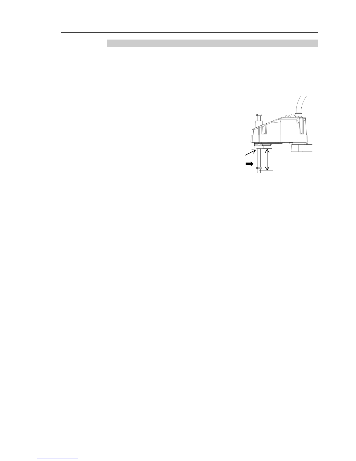
1.2.1 Strength of the Ball Screw Spline
If a load exceeding the allowable value is applied to the ball screw spline, it may not work
properly due to deformation or breakage of the shaft. If the ball screw spline is applied
the load exceeding the allowable value, it is necessary to replace the ball screw spline unit.
The allowable loads differ depending on distance where the load is applied to. For
calculating the allowable load, see the calculation formula below.
[Allowable bending moment]
LS3: M=13,000 N∙mm
LS6: M=27,000 N∙mm
Example: If 100 N
load is applied
at 200 mm from
the end of the spline nut
[Moment]
M=F∙L=100∙200=20,000 N∙mm
End of the
spline nut
F
L
Page 20
Setup & Operation 1. Safety
6 LS Rev.10
1.3 Operation Safety
The following items are sa fety precautions for qualified Oper at or per sonnel:
WARNING
■
Please carefully read the
Safety-related Requirements in the Safety chapter of
the
Safety and Installation manual before operat ing the robot sy stem. Operating
the robot system without understanding the safety requirements is extremely
hazardous and may result in serious bodily injury and/or sever
e equipment
damage to the robot system.
■
Do not enter the operating area of the Manipulator while the power to the robot
system is turned ON. Entering the operating area with the power ON is
extremely hazardous and may cause serious safety problems as the Manipulator
may move even if it seems to
be stopped.
■
Before operating the robot system, make sure that no one is inside the
safeguarded area.
The robot system can be operated in the mode for teaching
even when someone is inside the safeguarded area.
The motion of the Manipulator is always i
n restricted (low speed and low power)
status to secure the safety of an operator.
However, operating the robot system
while someone is inside the safeguarded area is extremely hazardous and may
result in serious safety problems in case that the Manipulator moves
unexpectedly.
■
Immediately press the Emergency Stop switch whenever the Manipulator moves
abnormally while the robot system is operated.
Continuing the operation while
the Manipulator moves abnormally is extremely hazardous and may result in
serious bodily injury and/or s evere equipment damage to the robot system.
WARNING
■
To shut off power to the robot system, pull out the power plug from the power
source.
Be sure to connect the AC power cable to a power receptacle. DO
NOT connect it
directly to a factory power sour ce.
■
Before performing any replacement procedure, turn OFF the
Controller and
related equipment, and then pull out the power plug from the power source.
Performing any replacement procedure with the power ON is extremely
hazardous and may result in electric shock and/or malfunction of the robot
system.
■
Do not insert or pull out th e motor c onnec tors w hil e the pow er to the r obot sy ste m
is turned ON.
Inserting or pulling out the mot or con nector s with t he power O N is
extremely hazardous and may result in serious bodily injury as the Manipulator
may move abnormally, and also may result in electric shoc k an d/or malfu ncti on of
the robot system.
Page 21
Setup & Operation 1. Safety
LS Rev.10 7
CAUTION
■
Whenever possible, only one person should operate the robot system.
If it is
necessary to operate t he r obot sy ste m with mor e tha n one per s on, en sure th at al l
people involved commu ni cate with each other as to what t hey are doing and take
all necessary safety precautions.
■
Joint #1, #2, and #4:
If the joints are operated
repeatedly with the op erat ing ang le less t han 5 degr ees,
they may get damaged early because the bearings are likely to cause oil film
shortage in such situation. To prevent early breakdown, move the joints larger
than 50 degrees
for about five to ten t imes a day.
Joint #3:
If the up
-and-down motion of the hand is less than 10 mm, move the joint a hal f of
the maximum stroke for five to ten times a day.
■
Oscillation (resonance) may
occur continuously in low speed Manipulator motion
(Speed:
approx. 5 to 20%) depending on combination of Arm orientat ion a nd end
effector load. Oscillation arises from natural oscillation frequency of the Arm
and can be controlled by follow in g measures.
Changing Manipulator speed
Changing the teach points
Changing the end effe ct or load
Page 22

Setup & Operation 1. Safety
8 LS Rev.10
1.4 Emergency Stop
Emergency stop motions of the Manipulator vary depending on the controller firmware.
See the section for the Controller firmware of your Controller.
1.4.1 Controller Firmware Ver. 7.0.2.3 or earlier
If the Manipulator moves abnormally during operation, immediately press the Emergency
Stop switch. Stops the power supply to the motor, and the arm stops in the shortest
distance with the dynamic brake and mechanical brake.
However, avoid pressing the Emergency Stop switch unnecessarily while the Manipulator
is running normally. Otherwise, the Manipulator may hit the peripheral equipment since
the operating trajectory until the robot system stops is different from that in normal
operation. It may also result in short life of the reduction gear unit due to the shock or
the electromagnetic brake due to the worn friction plate.
To place the system in emergency mode during normal operation, press the Emergency
Stop switch when the Manipulator is not moving.
Refer to the Controller manual for instructions on how to wire the Emergency Stop switch
circuit.
Do not press the Emergency Stop switch unnecessarily while the Manipulator is operating.
Pressing the switch during the operation makes the brakes work. This will shorten the
life of the brakes due to the worn friction plates.
Normal brake life: About 2 years (when the brakes are used 100 times/day)
Do not turn OFF the Controller while the Manipulator is operating.
If you attempt to stop the Manipulator in emergency situations such as “Safeguard Open”,
make sure to stop the Manipulator using the Emergency Stop switch of the Controller.
If the Manipulator is stopped by turning OFF the Controller while it is operating,
following problems may occur.
Reduction of the life and damage of the reduction gear unit
Position gap at the joints
In addition, if the Controller was forced to be turned OFF by blackouts and the like while
the Manipulator is operating, make sure to check the following points after power
restoration.
Whether or not the reduction gear is damaged
Whether or not the joints are in their proper positions
If there is a position gap, perform calibration by referring to the Maintenance 13.
Calibration in this manual.
Before using the Emergency Stop switch, be aware of the followings.
- The Emergency Stop (E-STOP) switch should be used to stop the Manipulator only
in case of emergencies.
- To stop the Manipulator operating the program except in emergency, use Pause (halt)
or STOP (program stop) commands.
Pause and STOP commands do not turn OFF the motors. Therefore, the brake does
not function.
- For the Safeguard system, do not use the circuit for E-STOP.
Page 23
Setup & Operation 1. Safety
LS Rev.10 9
For details of the Safeguard system, refer to the following manuals.
EPSON RC+ User’s Guide
2. Safety - Installation and Design Precautions - Safeguard System
Safety and Installation
2.6 Connection to EMERGENCY Connector
To check brake problems, refer to the following manuals.
Manipulator Manual Maintenance
2.1.2 Inspection Point - Inspection While the Power is ON
(Manipulator is operating)
Safety and Installation
5.1.1 Manipulator
- Inspection While the Power is ON (Manipulator is operating)
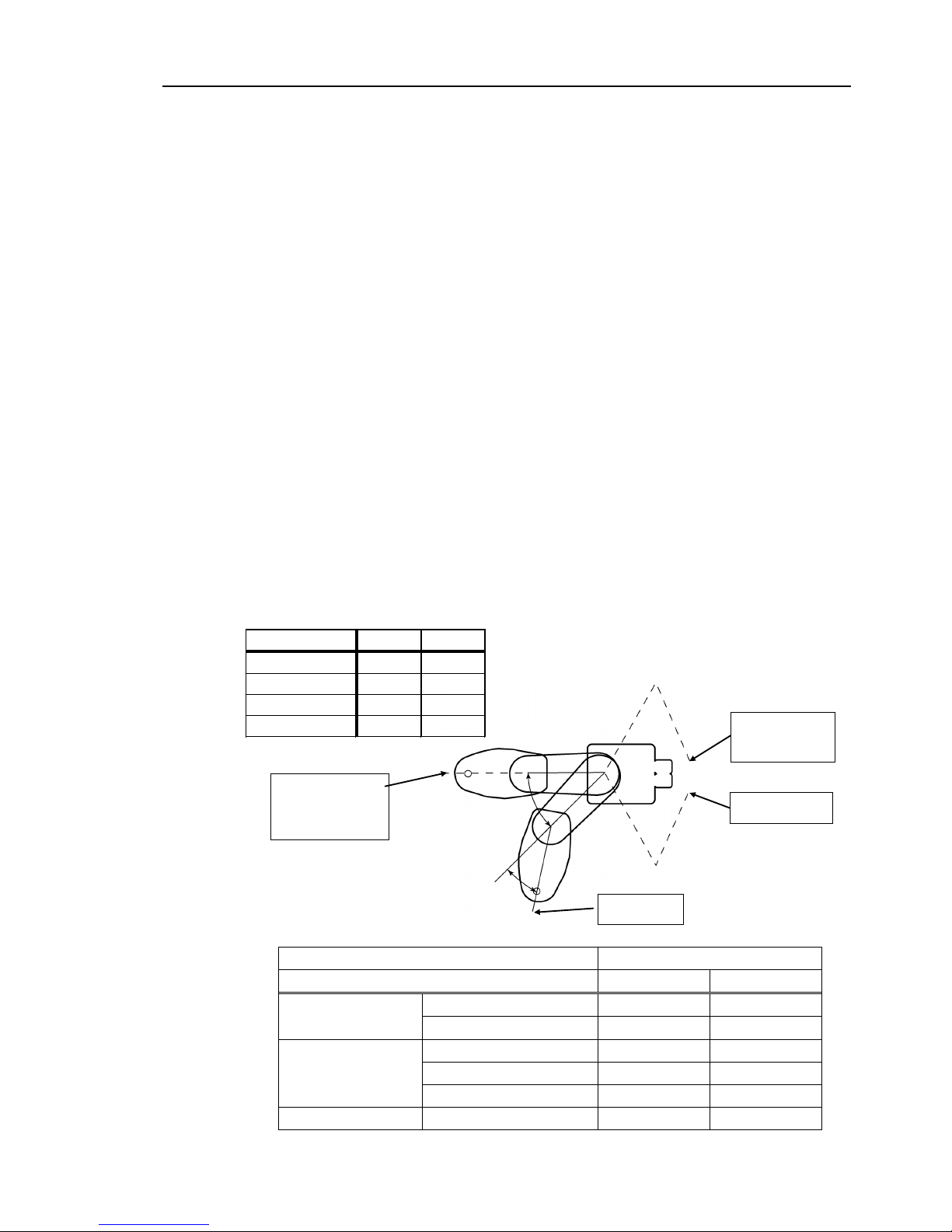
Free running distance in emer gency
The operating Manipulator cannot stop immediately after the Emergency Stop switch is
pressed.
The free running time/angle/distance of the Manipulator are shown below. However,
remember that the values vary depending on following conditions.
Weight of the end effector Weight of work piece Operating pose
Weight Speed Accel etc.
Conditions for
Measurement
LS3-401*
LS6-602*
Accel Setting
100
100
Speed Setting
100
100
Load [kg]
3
4
Weight Setting
3
4
Joint #1
Point where the
emergency stop
signal is input
Start point of
operation
Target point
Stop point
Joint #2
Controller RC90
Manipulator LS3-401* LS6-602*
Free running time
Joint #1 + Joint #2 [sec.] 0.4 0.7
Joint #3 [sec.] 0.1 0.2
Free running angle
Joint #1 [deg.] 110 100
Joint #2 [deg.] 20 45
Joint #1 + Joint #2 [deg.] 130 130
Free running distance Joint #3 [mm] 20 50
Page 24

Setup & Operation 1. Safety
10 LS Rev.10
1.4.2 Controller Firmware Ver. 7.0.2.4 or later
If the Manipulator moves abnormally during operation, immediately press the Emergency
Stop switch. Pressing the Emergency Stop switch immediately changes the manipulator
to deceleration motion and stops it at the maximum deceleration speed.
However, avoid pressing the Emergency Stop switch unnecessarily while the Manipulator
is running normally. Pressing the Emergency Stop switch locks the brake and it may
cause wear on the friction plate of the brake, resulting in the short life of the brake.
Normal brake life cycle: About 2 years (when the brakes are used 100 times/day)
To place the system in emergency mode during normal operation, press the Emergency
Stop switch when the Manipulator is not moving.
Refer to the Controller manual for instructions on how to wire the Emergency Stop switch
circuit.
Do not turn OFF the Controller while the Manipulator is operating.
If you attempt to stop the Manipulator in emergency situations such as “Safeguard Open”,
make sure to stop the Manipulator using the Emergency Stop switch of the Controller.
If the Manipulator is stopped by turning OFF the Controller while it is operating,
following problems may occur.
Reduction of the life and damage of the reduction gear unit
Position gap at the joints
In addition, if the Controller was forced to be turned OFF by blackouts and the like while
the Manipulator is operating, make sure to check the following points after power
restoration.
Whether or not the reduction gear is damaged
Whether or not the joints are in their proper positions
If there is a position gap, perform calibration by referring to the Maintenance 13.
Calibration in this manual.
Before using the Emergency Stop switch, be aware of the followings.
- The Emergency Stop (E-STOP) switch should be used to stop the Manipulator only
in case of emergencies.
- To stop the Manipulator operating the program except in emergency, use Pause (halt)
or STOP (program stop) commands
Pause and STOP commands do not turn OFF the motors. Therefore, the brake does
not function.
- For the Safeguard system, do not use the circuit for E-STOP.
For details of the Safeguard system, refer to the following manuals.
EPSON RC+ User’s Guide
2. Safety - Installation and Design Precautions - Safeguard System
Safety and Installation
2.6 Connection to EMERGENCY Connector
Page 25

Setup & Operation 1. Safety
LS Rev.10 11
To check brake problems, refer to the following manuals.
Manipulator Manual Maintenance
2.1.2 Inspection Point - Inspection While the Power is ON
(Manipulator is operating)
Safety and Installation
5.1.1 Manipulator
- Inspection While the Power is ON (Manipulator is operating)
Free running distance in emer gency
The operating Manipulator cannot stop immediately after the Emergency Stop switch is
pressed.
The free running time/angle/distance of the Manipulator are shown below. However,
remember that the values vary depending on following conditions.
Weight of the end effector Weight of work piece Operating pose
Weight Speed Accel etc.
Conditions for
Measurement
LS3-401*
LS6-502*, 602*, 702*
Accel Setting
100
100
Speed Setting
100
100
Load [kg] 3 6
Weight Setting 3 6
Joint #1
Point where the
emergency stop
signal is input
Start point of
operation
Target point
Stop point
Joint #2
Controller RC90
Manipulator LS3-401* LS6-502* LS6-602* LS6-702*
Free running
time
Joint #1 + Joint #2 [sec.] 0.4 0.4 0.7 0.7
Joint #3 [sec.] 0.1 0.2
Free running
angle
Joint #1 [deg.] 110 42 100 85
Joint #2 [deg.] 20 42 45 50
Joint #1 + Joint #2 [deg.] 130 84 130 135
Free running
distance
Joint #3 [mm] 20 90
Page 26
Setup & Operation 1. Safety
12 LS Rev.10
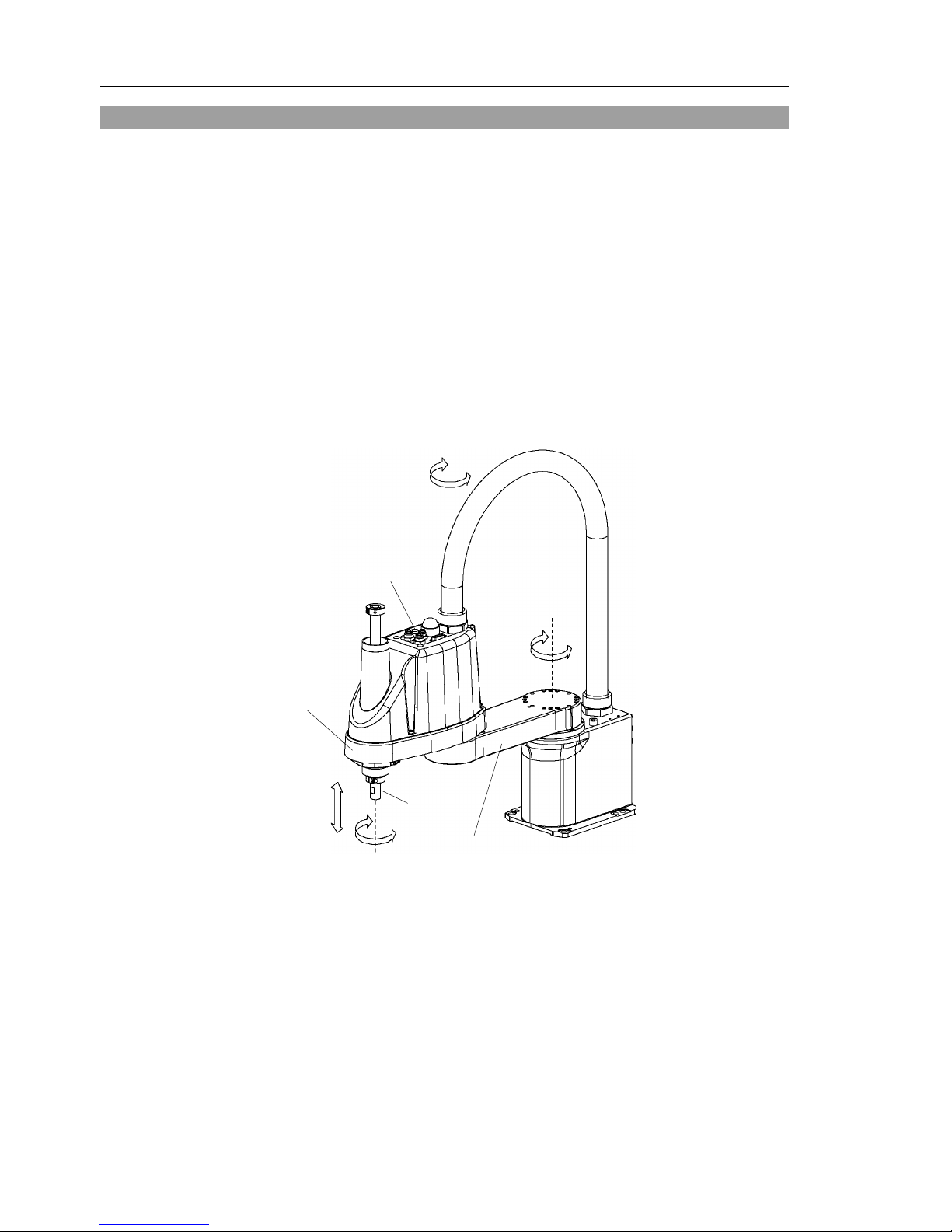
1.5 Emergency Movement Without Drive Power
When the system is placed in emergency mode, push the arm or joint of the Manipulator
by hand as shown below:
Arm #1 Push the arm by hand.
Arm #2 Push the arm by hand.
Joint #3 The joint cannot be moved up/down by hand until the solenoid
brake applied to the joint has been released. Move the joint
up/down while pressing the brake release switch.
Joint #4 LS3: Rotate the shaft by hand.
LS6: The shaft cannot be rotated b y hand until the solenoid brake
applied to the shaft has been released. Move the shaft
while pressing the brake release switch.
+
−
+
−
+
−
+
−
Joint #3
brake release switch
Joint #1
(rotating)
Joint #2
(rotating)
Joint #3
(up and down)
Joint #4
(rotating)
Arm #1
Arm #2
Shaft
(Figure: LS3-401S)
LS3: The brake release switch affects only Joint #3. When the brake release switch is
pressed in emergency mode, the brake for Joint #3 is released.
Be careful of the shaft while the brake release switch is pressed because the s haft may
be lowered by the weight of an end effector.
LS6: The brake release switch affects both Joints #3 and #4. When the brake release
switch is pressed in emergency mode, the brake for both Joints #3 and #4 are released
simultaneously.
Be careful of the shaft falling and rotating while the brake release switch is pressed
because the shaft may be lowered by the weight of an end effector.
NOTE
Page 27
Setup & Operation 1. Safety
LS Rev.10 13
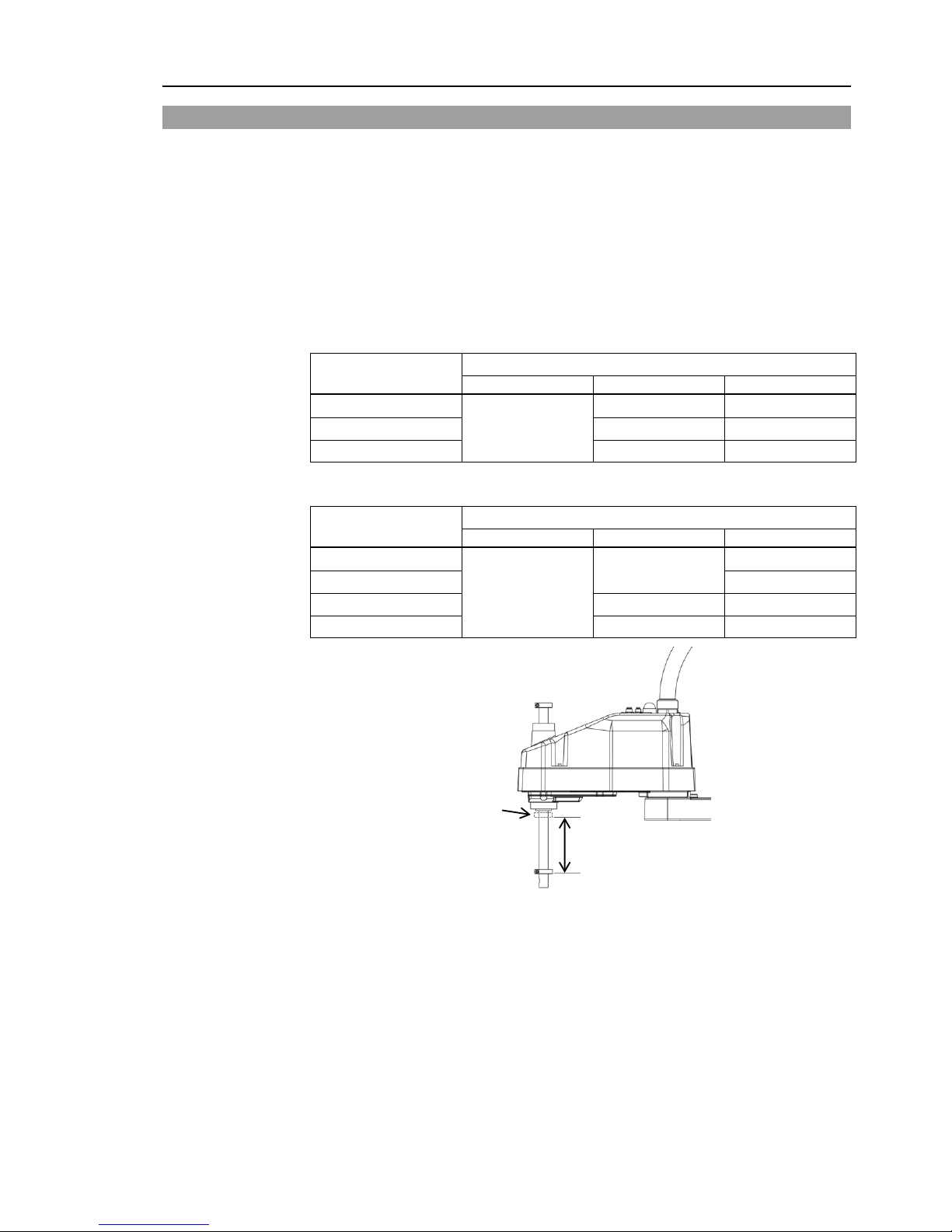
1.6 ACCELS Setting for CP Motions
To make the Manipulator move in CP motion, see the following and set ACCELS properly
according to the tip load and the Z-axis height.
Improper setting may cause following problems.
- Decline in the life and damage of the ball screw spline
Set ACCELS as follows according to the Z-axis height.
ACCELS setting values by Z-axis height and tip l oad
LS3
Z-axis height
(mm)
Tip load
1 kg or less
2 kg or less
3 kg or less
__- 0 > Z >= _- 50
25000 or less
25000 or less 22500 or less
_- 50 > Z >= - 100
22500 or less
15000 or less
- 100 > Z >= - 150
17500 or less
10000 or less
LS6
Z-axis height
(mm)
Tip load
2 kg or less
4 kg or less
6 kg or less
__- 0 > Z >= _- 50
25000 or less
25000 or less
25000 or less
_- 50 > Z >= - 100
15000 or less
- 100 > Z >= - 150
17500 or less
12500 or less
- 150 > Z >= - 200
15000 or less
10000 or less
Z
Z-axis height 0
(Origin position)
If the Manipulator is operated in CP motion with the wrong set values, make sure to check
the following points.
- Whether or not the ball screw spline shaft is deformed or bent
NOTE
Page 28
Setup & Operation 1. Safety
14 LS Rev.10
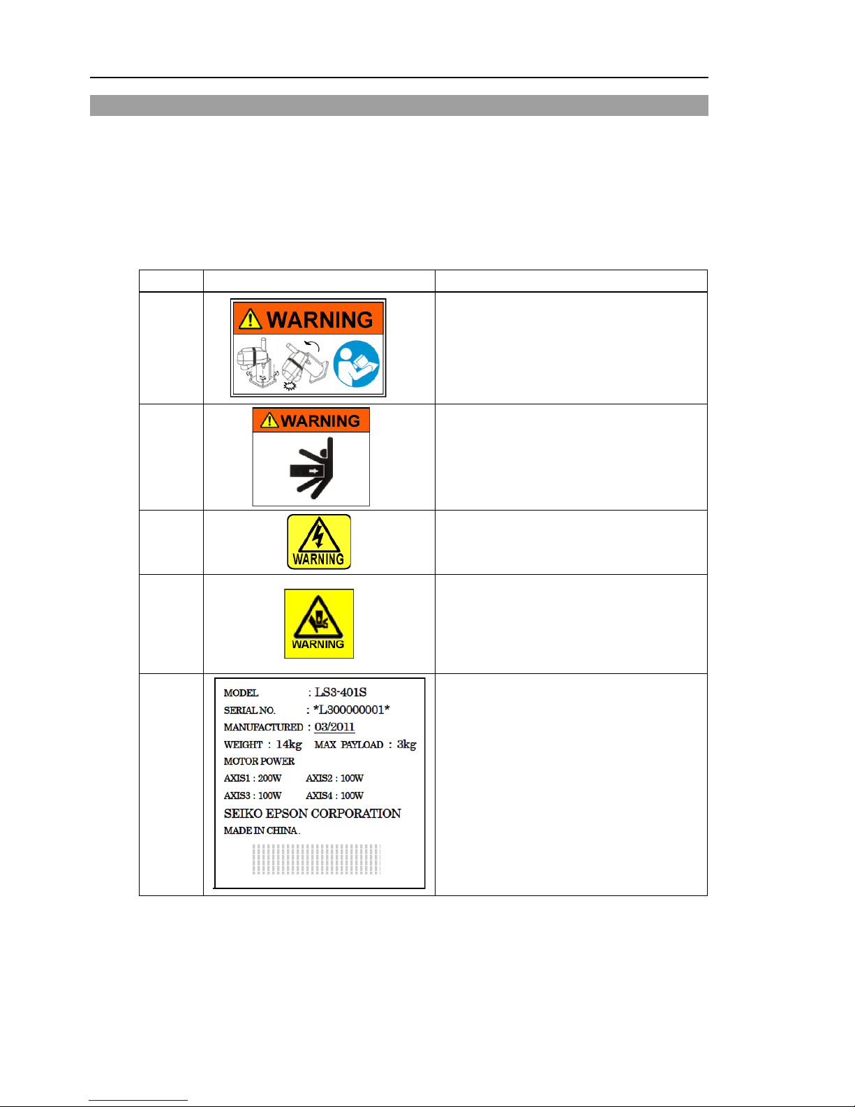
1.7 Warning Labels
The Manipulator has the following warning labels.
The warning labels are attached around the locations where specific dangers exist.
Be sure to comply with descriptions and warnings on the labels to operate and maintain
the Manipulator safely.
Do not tear, damage, or remove the warning labels. U se meticulous care when handling
those parts or units to which the following warning labels are attached as well as the
nearby areas.
Location Warning Label NOTE
A
Before loosening the base mo untin g scr ews, hold
the arm and secure it tightly with a band to
prevent hands or fingers from being caught in the
Manipulator.
B
Do not enter the operation area while the
Manipulator is moving. The robot arm may
collide against the operator. This is extremely
hazardous and may result in serious safety
problems.
C
Hazardous voltage exists while the Manipula tor is
ON. To avoid electric shock, do not touch any
internal electric parts.
D
You can catch your hand or fingers between the
shaft and cover when bringing your hand close to
moving parts.
* Manipulators with bellows do not have this label
for no danger of your hand or fingers being
caught.
E
Page 29
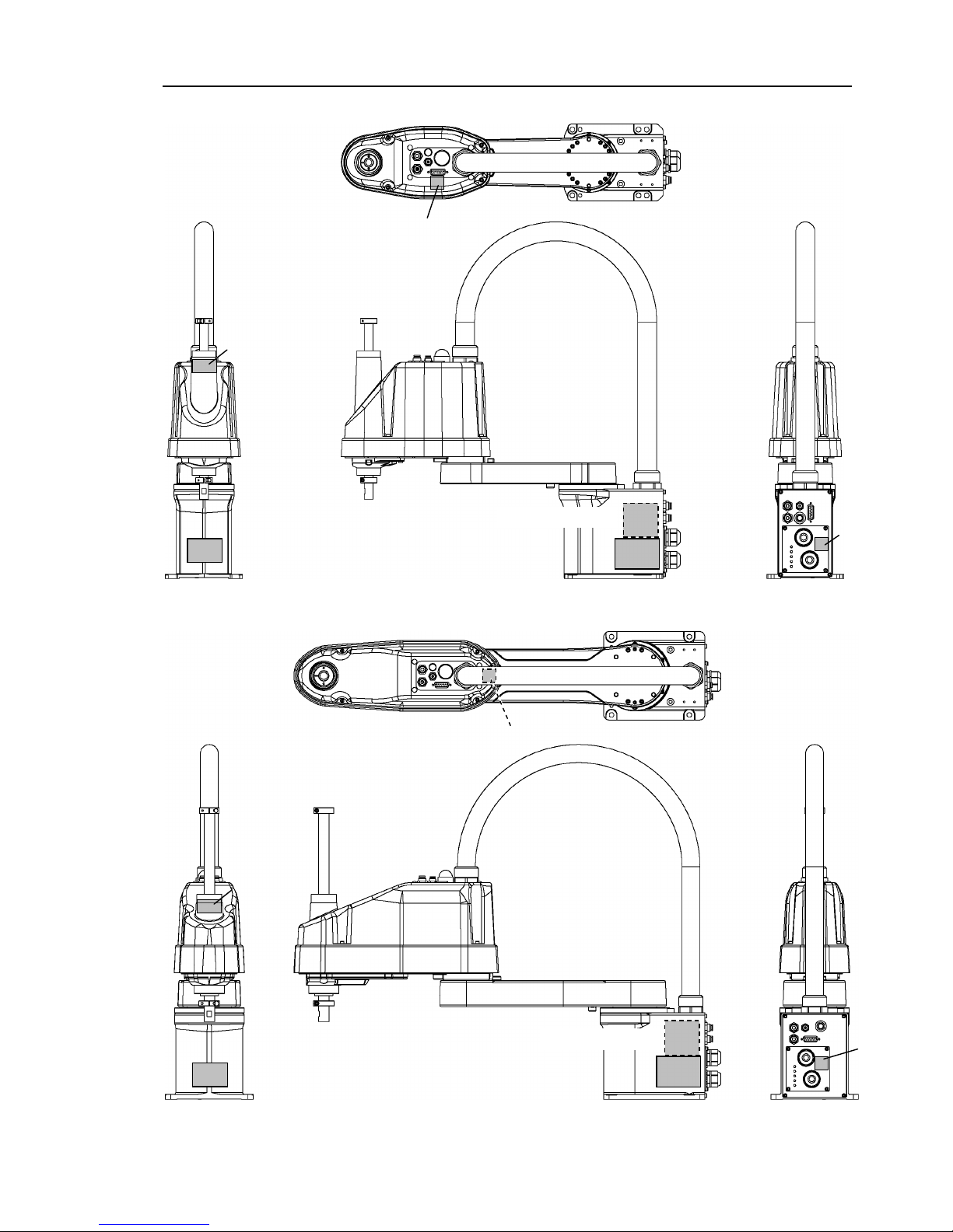
Setup & Operation 1. Safety
LS Rev.10 15
LS3
C
A
D
B
C
E
(Opposite side)
(Figure: LS3-401S)
LS6
C (Arm Top Cover
)
A
D
B
C
E
(Opposite side)
(Figure: LS6-602S)
Page 30

Setup & Operation 2. Specifications
16 LS Rev.10
2. Specifications
2.1 Features of LS series Manipulators
The LS series Manipulators are advanced manipulators pursuing high speed and high
cost-performance.
The features of the LS series Manipulators are as follows:
Resolver for the Position Detector
It includes no electrical components; therefore it has high resistance to environment
and hardly breaks down.
It mounts the resolver board and battery inside the manipulator; therefore the
calibration is not required when you disconnect the M/C cable.
Large Capacity
It supports the U-axis allowable moment up to 0.12 kg·m
2
(LS6) / 0.05 kg·m2 (LS3).
It stably handles large loads by optimized control based on the each load.
Tact Time Improvement b y High-speed Motion
It improves the tact time of long-range movements by readjusting the highest speed.
(LS3)
It improves the tact time of delicate movements by acceleration/deceleration speed
optimized for each payload and stop short technology.
Page 31

Setup & Operation 2. Specifications
LS Rev.10 17
2.2 Model Number
LS3-40 1 S
Environment
S
: Standard
C
: Cleanroom
Joint #3 stroke
1
: 150 mm : Standard-Model
: 120 mm : Cleanroom-Model (with bellows)
2
: 200 mm : Standard-Model
: 170 mm : Cleanroom-Model (with bellows)
Arm length
40
: 400 mm
50
: 500 mm
60 : 600 mm
70 : 700 mm
Payload
3
: 3 kg
6
: 6 kg
Environment
Cleanroom-model
This model has additional features that reduce dust emitted by the Manipulator to enable
use in clean room environments.
For details on the specifications, refer to Setup & Operation: 2.4 Specifications.
Models
Payload Arm length Environment Joint #3 stroke Model Number
3 kg 400 mm
Standard
150 mm
LS3-401S
Cleanroom
120 mm
LS3-401C
6 kg
500 mm
Standard
200 mm
LS6-502S
Cleanroom
170 mm
LS6-502C
600 mm
Standard
200 mm
LS6-602S
Cleanroom
170 mm
LS6-602C
700 mm
Standard
200 mm
LS6-702S
Cleanroom
170 mm
LS6-702C
Page 32

Setup & Operation 2. Specifications
18 LS Rev.10
2.3 Part Names and Outer Dimensions
2.3.1 LS3
Standard-Model LS3-401S
Joint #3
Brake release switch
Arm #1
Arm #2
Base
Shaft
MT label
(only for custom
specification)
Signature label
(Serial No.
of Manipulator)
Signal cable
Power cable
Fittings (black or blue)
for ø4 mm pneumatic tube
Fittings (black or blu e)
for ø6 mm
pneumatic tube
Fittings (white)
for ø6 mm
pneumatic tube
User connector
(15-pin
D-sub connector)
LED lamp
CE label
- The brake release switch affects only Joint #3. When the brake release switch is
pressed in emergency mode, the brake for Joint #3 is released.
- While the LED lamp is on, the current is being applied to the manipulator.
Performing any work with the power ON is extremely hazardous and it may result in
electric shock and/or improper function of the robot system. Make sure to turn OFF
the controller power before the maintenance work.
NOTE
Page 33

Setup & Operation 2. Specifications
LS Rev.10 19
Standard-Model LS3-401S
shaft diameter
Max.ø11 through hole
mechanical stop diameter
Conical hole Ø3,90°
1 mm
flat
Detail view from A
90 or more
Space for cables
(*) indicates the stroke margin
by mechanical stop.
Page 34

Setup & Operation 2. Specifications
20 LS Rev.10
Cleanroom-Model LS3-401C
The following figures show the additional parts and specifications for Cleanroom-model
when compared with the Standard-model in appearance.
Upper bellows
Exhaust port
Lower bellows
Page 35

Setup & Operation 2. Specifications
LS Rev.10 21
Cleanroom-Model LS3-401C
(*) indicates the stroke margin
by mechanical stop.
90 or more
(Space for cables)
φ16 h7 shaft diameter
Max.ø11 through hole
φ30 mechanical stop diameter
Conical hole Ø3,90°
1 mm flat
Detail view from A
Page 36

Setup & Operation 2. Specifications
22 LS Rev.10
2.3.2 LS6
Standard-Model LS6-**2S
Joint #3
Brake release switch
Arm #1
Arm #2
Base
Shaft
MT label
(only for custom
specification)
Signature label
(Serial No.
of Manipulator)
Signal cable
Power cable
Fittings (blue)
for ø4 mm pneumatic tube
Fittings (blue)
for ø6 mm
pneumatic tube
Fittings (white)
for ø6 mm
pneumatic tube
User connector
(15-pin D-sub
connector)
LED lamp
CE label
- The brake release switch affects both Joints #3 and #4. When the brake release switch
is pressed in emergency mode, the brakes for both Joint #3 and Joint #4 are released
simultaneously.
- While the LED lamp is on, the current is being applied to the manipulator.
Performing any work with the power ON is extremely hazardous and it may result in
electric shock and/or improper function of the robot system. Make sure to turn OFF
the controller power before the maintenance work.
NOTE
Page 37

Setup & Operation 2. Specifications
LS Rev.10 23
Standard-Model LS6-**2S
(*) indicates the stroke margin by mechanical stop.
Detail view from A
Page 38

Setup & Operation 2. Specifications
24 LS Rev.10
Cleanroom-Model LS6-**2C
The following figures show the additional parts and specifications for Cleanroom-model
when compared with the Standard-model in appearance.
Upper bellows
Exhaust port
Lower bellows
Page 39

Setup & Operation 2. Specifications
LS Rev.10 25
Cleanroom-Model LS6-**2C
(*) indicates the stroke margin by mechanical stop.
Detail view from A
Page 40

Setup & Operation 2. Specifications
26 LS Rev.10
2.4 Specifications
Item
LS3-401*
LS6-**2*
Arm length
Arm #1, #2 400 mm
50
500 mm
60
600 mm
70
700 mm
Arm #1 225 mm
50
225 mm
60
325 mm
70
425 mm
Arm #2
175 mm
275 mm
Max. operating speed *1
Joints #1, #2 6000 mm/s
50
6150 mm/s
60
6800 mm/s
70
7450 mm/s
Joint #3
1100 mm/s
Joint #4
2600 deg./s
2000 deg/s
Repeatability
Joints #1, #2
± 0.01 mm
± 0.02 mm
Joint #3
± 0.01 mm
Joint #4
± 0.01 deg.
Payload (Load)
Rated
1 kg
2 kg
Max.
3 kg
6 kg
Joint #4 allowable
moment of inertia *2
Rated
0.005 kg·m2
0.01 kg·m2
Max.
0.05 kg·m2
0.12 kg·m2
Resolution
Joints #1
0.000439 deg./pulse
0.000275 deg/pulse
Joint #2
0.000439 deg./pulse
Joint #3
0.000799 mm/pulse
0.000814 mm/pulse
Joint #4
0.001927 deg./pulse
0.001465 deg/pulse
Hand
Shaft diameter
ø 16 mm
ø 20 mm
Through hole
ø 11 mm
ø 14 mm
Mounting hol e
120 × 120 mm, 135 × 120 mm
(Free choice of either hole.)
150 × 150 mm
4-M8
Weight (cables not included)
14 kg : 31 lb
50
17 kg : 37.5 lb
60
17 kg : 37.5 lb
70
18 kg : 39.7 lb
Driving metho d
All joints
AC servo motor
Motor
energy consumption
Joint #1
200 W
Joint #2
100 W
200 W
Joint #3
100 W
Joint #4
100 W
Option
Installation environment
Cleanroom *3
Joint #3 down force
100 N
Installed wire for customer use
15 (15 pin: D-sub)
Installed pneumatic
tube for customer use
2 pneumatic tubes (ø6 mm) : 0.59 MPa (6 kgf/cm2 : 86 psi)
1 pneumatic tubes (ø4 mm) : 0.59 MPa (6 kgf/cm2 : 86 psi)
Environmenta
l requirements
Ambient Temp.
5 to 40 degrees C (with minimum temperatur e variation)
Ambient relative humidity
10 to 80% (no condensation)
Noise level *4
L
Aeq
= 70 dB (A)
Applicable Controller
RC90
Page 41

Setup & Operation 2. Specifications
LS Rev.10 27
Item
LS3-401*
LS6-**2*
Assignable Value
( ) Default va l ues
SPEED
1 to (5) to100
ACCEL *5
1 to (10) to 120
SPEEDS
1 to (50) to 2000
ACCELS
1 to (200) to 25000
FINE
0 to (1250) to 65000
WEIGHT
0,175 to (1,175) to 3,175
0,275 to (2,275) to 6,275
Safety standard
CE Mark
EMC Directive, Machinery Directive, RoHS Directive
KC Mark, KCs Mark
ANSI/RIA R15.06-2012
NFPA 79 (2007 Edition)
Item
LS3-401S
LS3-401C
LS6-**2S
LS6-**2C
Max.
motion range
Joint #1
± 132 deg
Joint #2
± 141 deg
± 150 deg
Joint #3
150 mm
120 mm
200 mm
170 mm
Joint #4
± 360 deg
Max.
pulse range
Joint #1
− 95574~505174 pulse
− 152918~808278 pulse
Joint #2
± 320854
pulse
± 341334
pulse
Joint #3
− 187734~0 pulse
− 150187~0 pulse
− 245760~0 pulse
− 208896~0 pulse
Joint #4
± 186778 pulse
± 245760 pulse
*1: In the case of PTP command.
Maximum operating speed for CP command is 2000 mm/s on horizontal plane.
*2: In the case where the center of gravity is at the center of Joint #4.
If the center of gravity is not at the center of Joint #4, set the parameter using Inertia command.
*3: The exhaust system in the Cleanroom-model Manipulator draws air from the base interior and arm cover
interior together.
A crack or other opening in the base unit can cause loss of negative air pressure in the outer part of the
arm, which can cause increased dust emission.
Seal the exhaust port and the exhaust tube with vinyl tape so that the joint is airtight.
If the exhaust flow is not sufficient, dust particle emission may exceed the specified maximum level.
Cleanliness level : Class ISO 4 (ISO14644-1)
Exhaust System : Exhaust port diameter : Inner diameter: ø12 mm / Outer diameter: ø16 mm
Exhaust tube : Polyurethane tube
Outer diameter: ø12 mm (Inner diameter:ø8 mm) or
Inner diameter ø16mm
Recommended exhaust flow rate : approx. 1000 cm
3
/s (Normal)
*4: Conditions of Manipulator during measurement as follows:
Operating conditions : Under rated load, 4-joints simultaneous motion, maximum speed, maximum
acceleration, and duty 50%.
Measurement point : In front of the Manipulator, 1000 mm apart from the motion range, 50 mm above
the base-installed surface.
*5: In general use, Accel setting 100 is the optimum setting that maintains the balance of acceleration and
vibration when positioning. Although values larger than 100 can be set to Accel, it is recommended to
minimize the use of large values to necessary motions since operating the manipulator continuously with
the large Accel setting may shorten the product life remarkably.
Page 42

Setup & Operation 2. Specifications
28 LS Rev.10
2.5 How to Set the Model
The Manipulator model for your system has been set before shipment from the factory.
It is normally not required to change the model when you receive your system.
CAUTION
■
When you need to change the setting of t he Manipu lator mo del, be sure to s et the
Manipulator model properly.
Improper setting of the Manipulator model may
result in
abnormal
or no operation of the Manipulator and/or cause safety
problems.
If an MT label is attached to the rear of a Manipulator, the Manipulator has custom
specifications. The custom specifications may require a different configuration
procedure; check the custom specifications number described on the MT label and contact
us when necessary.
The Manipulator model can be set from software.
Refer to the chapter Robot Configuration in the EPSON RC+ User’s Guide.
NOTE
Page 43

Setup & Operation 3. Environments an d Installation
LS Rev.10 29
3. Environments and Installation
3.1 Environmental Conditions
A suitable environment is necessary for the robot system to function properly and safely.
Be sure to install the robot system in an environment that meets the following conditions:
Item
Conditions
Ambient temperature *
5 to 40°C (with minimum temperature variation)
Ambient relative humidity
10 to 80% (no condensation)
First transient burst noise
2 kV or less
Electrostatic noise 4 kV or less
Environment · Install indoors.
· Keep away from direct sunlight.
· Keep away from dust, oily smoke, salinity, metal
powder or other contaminants.
· Keep away from flammable or corrosive solvents
and gases.
· Keep away from water.
· Keep away from shocks or vibrations.
· Keep away from sources of electric noise.
Manipulators are not suitable for operation in harsh environments such as painting areas,
etc. When using Manipulators in inadequate environments that do not meet the above
conditions, please contact us.
* The ambient temperature conditions are for the Manipulators only. For the Controller
the Manipulators are connected to, refer to the Controller manual.
Special Environmental Conditions
The surface of the Manipulator has general oil resistance. However, if your requirements
specify that the Manipulator must withstand certain kinds of oil, please consult your
distributor.
Rapid change in temperature and humidity can cause condensation inside the Manipulator.
If your requirements specify that the Manipulator handles food, please consult your
distributor to check whether the Manipulator gives damage to the food or not.
The Manipulator cannot be used in corrosive environments where acid or alkaline is used.
In a salty environment where the rust is likely to gath er, the Manipulator is susceptible to
rust.
WARNING
■
Use an earth leakage breaker on the AC power cable of the
Controller to avoid
electric shock and circuit breakdown caused by
short circuit.
Prepare the earth leakage br a
ke that pertains the Controller you are using.
For details, refer to the
Controller manual.
CAUTION
■
When cleaning the Manip ulator, do not rub it strongly with alcohol or
benzene.
It may lose luster on the
coated face.
NOTE
Page 44

Setup & Operation 3. Environments and Installation
30 LS Rev.10
3.2 Base Table
A base table for anchoring the Manipulator is not supplied. Please make or obtain the
base table for your Manipulator. The shape and size of the base table differs depending
on the use of the robot system. For your reference, we list some Manipulator table
requirements here.
The torque and reaction force produced by the movement of the Manipulator are as
follows:
LS3
LS6
Max. Reaction torque on the horizontal plate
250 Nm
350 Nm
Max. Horizontal reaction force
1000 N
1700 N
Max. Vertical reaction force
1000 N
1500 N
The threaded holes required for mounting the Manipulator base are M8. Use mounting
bolts with specifications conforming to ISO898-1 property class: 10.9 or 12.9.
For dimensions, refer to Setup & Operation: 3.3 Mountin g Dimensions.
The plate for the Manipulator mounting face should be 20 mm thick or more and made of
steel to reduce vibration. The surface roughness of the steel plate should be 25 μm or
less.
The table must be secured on the floor or wall to prevent it from moving.
The Manipulator must be installed horizontally.
When using a leveler to adjust the height of the base table, use a screw with M16 diameter
or more.
If you are passing cables through the holes on the base table, see the figures below.
Power Cable
Connector
Signal Cable
Connector
44
18
63
15
M/C Cables
(Unit : mm)
40
80
Do not remove the M/C cables from the Manipulator.
For environmental conditions regarding space when placing the Controller on the base
table, refer to the Controller manual.
WARNING
■
To ensure safety, a safeguard must be installed
for the robot system.
For details on the
safeguard, refer to the EPSON RC+ User’s Guide.
NOTE
Page 45

Setup & Operation 3. Environments an d Installation
LS Rev.10 31
3.3 Mounting Dimensions
The maximum space described in figures shows that the radius of the end effector is 60
mm or less. If the radius of the end effector exceeds 60 mm, define the radius as the
distance to the outer edge of maximum space.
If a camera or solenoid valve extends outside of the arm, set the maximum range including
the space that they may reach.
Be sure to allow for the following extra spaces in addition to the space required for
mounting the Manipulator, Controller, and peripheral equipment.
Space for teaching
Space for maintenance and inspection
(Ensure a space to open the covers and plates for maintenance.)
Space for cables
The minimum bend radius of the power cable is 90 mm. When installing the cable, be
sure to maintain sufficient distance fro m obstacles. In addition, leave enough space for
other cables so that they are not bent forcibly.
Ensure distance to the safeguard from the maximum motion range is more than 100 mm.
3.3.1 LS3
Standard-Model: LS3-401S
Center of Joint #3
Maxim um space
Motion range
Area limited by mechanical stop
Base mounting face
Page 46

Setup & Operation 3. Environments and Installation
32 LS Rev.10
Cleanroom-Model: LS3-401C
Center of Joint #3
Maxim um space
Motion range
Area limited by mechanical stop
Base mounting face
Page 47

Setup & Operation 3. Environments an d Installation
LS Rev.10 33
3.3.2 LS6
Standard-Model: LS6-**2S
LS6-502S
LS6-602S
LS6
-702S
Motion range
Maximum
range
b
c
f
d
d
e
e
j
245
240
h
h
g
k
i
i
a
Base mounting face
Area limited by a mechanical stop
p
m
q
n
p
m
q
p
m
q
n
n
b
c
f
d
d
e
e
j
245
220
h
h
g
k
i
i
a
b
c
f
d
d
e
e
j
245
220
h
h
g
k
i
i
a
Center of Joint #3
LS6-502S
LS6-602S
LS6-702S
a
Arm #1 + Arm #2 length [mm]
500
600
700
b
Arm #1 length [mm]
225
325
425
c
Arm #2 length [mm]
275
d
Joint #1 motion angle [deg.]
132
e
Joint #2 motion angle [deg.]
150
f
(Motion ra nge)
138.1
162.6
232.0
g
(Motion range at the rear)
425.6
492.5
559.4
h
Angle of the Joint #1 mechanical stop [deg.]
2.8
i
Angle of the Joint #2 mechanical stop [deg.]
4.2
j
(Mechanical stop area)
121.8
142.5
214.0
k
(Mechanical stop area at the rear)
433.5
504.0
574.5
m
(Joint #3 motion range)
200
n
(Distance from the base mounting face)
51
p
(Joint #3 mechanical stop area upper end)
10.0
q
(Joint #3 mechanical stop area lower end)
11.8
Page 48

Setup & Operation 3. Environments and Instal lation
34 LS Rev.10
Cleanroom-Model: LS6-**2C
LS6-502C
LS6-602C
LS6-702C
Motion range
Maximum
range
b c f
d
d
e
e
j
270
300
h
h
g
k i i
a
Base mounting
face
Area limited by a mechanical stop
p
m
q
n
p
m
q
p
m
q
n
n
b
c
f
d
d
e
e
j
380
h
h
g
k
i
i
a
b
c
f
d
d
e
e
j
500
h
h
g
k
i
i
a
86.8
86.8
86.8
270
270
Center of Joint #3
LS6-502C
LS6-602C
LS6-702C
a
Arm #1 + Arm #2 length [mm]
500
600
700
b
Arm #1 length [mm]
225
325
425
c
Arm #2 length [mm]
275
d
Joint #1 motion angle [deg.]
132
e
Joint #2 motion angle [deg.]
150
f
(Motion range )
138.1
162.6
232.0
g
(Motion range at the rear)
425.6
492.5
559.4
h
Angle of the Joint #1 mechanical stop [deg.]
2.8
i
Angle of the Joint #2 mechanical stop [deg.]
4.2
j
(Mechanical stop area)
121.8
142.5
214.0
k
(Mechanical stop area at the rear)
433.5
504.0
574.5
m
(Joint #3 motion range)
170
n
(Distance from the base mounting face)
53
p
(Joint #3 mechanical stop area upper end)
6.0
q
(Joint #3 mechanical stop area lower end)
9.8
Page 49

Setup & Operation 3. Environments an d Installation
LS Rev.10 35
3.4 Unpacking and Transportation
THE INSTALLATION SHALL BE PREFORMED BY QUALIFIED INSTALLATION
PERSONNEL AND SHOULD CONFORM TO ALL NATIONAL AND LOCAL
CODES.
WARNING
■
Only authorized personnel
should perform sling work and operate a crane and a
forklift. When
these operations are performed by unauthorized personnel, it is
extremely hazardous and may result in serious bodily injury and/or severe
equipment damage to the robot system.
CAUTION
■
Using a cart or similar equipment, transport the Manipulator in the same manner
as it was delivered.
■
After
removing the bolts securing the Manipulator to the delivery equipment, the
Manipulator
can fall. Be careful not to get hands or fingers caught.
■
The arm is secured with a wire tie. Leav e the wire t ie secured unt il you finish the
installation so as not to get hands or f ingers caught
.
■
To carry the Manipulator, have two or more people to work on it and secure the
Manipulator to the delivery
equipment or hold the areas indicated in gray in the
figure (bottom of Arm #1 and bottom of the base) by hand.
When holding the bottom of the base by hand, be very careful not to get your
hands or fingers caught.
LS3-401*: approx. 14 kg: 31 lb.
LS6-502*: approx. 17 kg: 37.5 lb.
LS6-602*: approx. 17 kg: 37.5 lb.
LS6-702*: approx. 18 kg: 39.7 lb.
Figure : LS3-401S
■
Stabilize the Manipulator w ith your hands when hoist
ing it.
■
When transporting the Manipulator for a long distance, secure it to the delivery
equipment directly so that t he M anipulator never falls.
If necessary, pack the Manipulator in the same style as
it was delivered.
Page 50

Setup & Operation 3. Environments and Installation
36 LS Rev.10
3.5 Installation Procedure
CAUTION
■
The robot system
must be installed to avoid
interference with buildings,
structures, utilities, other
machines and equipment that may create a trapping
hazard or pinch points.
■
Oscillation (resonance) may
occur during operation depending on ri gidity of the
installation table.
If the oscillation occurs, improve rigidity of the table
or change the speed or
acceleration
and deceleration settings.
Page 51

Setup & Operation 3. Environments an d Installation
LS Rev.10 37
3.5.1 Standard-Model
CAUTION
■
Install the
Table T op Mounting Manipulator with two or more people.
The Manipulator weigh
ts are as f ollows. Be careful not to get hands, fingers, or
feet caught and/or have equipment damage
d by a fall of the Manipulator.
LS3-401*: approx. 14 kg: 31 lb.
LS6-502*: approx. 17 kg: 37. 5 lb.
LS6-602*: approx. 17 kg: 37. 5 lb.
LS6-702*: approx. 18 kg: 39. 7 lb.
(1)
Secure the base to the base table
with four bo
lts.
Use bolts
with specifications
conforming
to ISO898-1 Property
C
lass: 10.9 or 12.9.
Tightening torque:
32.0 N·m (326 kgf·cm)
10 mm
4-M8
×25
Screw Hole
(depth 20 mm
or more)
Spring
Washer
Plane
LS6 only
(2)
Using nippers, cut off the wire tie
binding
the shaft and arm retaining
bracket on the
base.
Wire tie
Bolt
M4×20
Bolt
M4×
20
LS6 only
(3)
Remove the bolts securing the wire
ties removed in step (2).
Remove the fixing sheet for
transportation which is attached to
the arm.
Make sure to remove the wire tie for
protection of mechanical
stop.
NOTE
NOTE
Page 52

Setup & Operation 3. Environments and Installation
38 LS Rev.10
3.5.2 Cleanroom-Model
(1) Unpack it outside of the clean room.
(2) Secure the Manipulator to delivery equipment such as a pallet with bolts so that the
Manipulator does not fall.
(3) Wipe off the dust on the Manipulator with a little alcohol or distilled water on a
lint-free cloth.
(4) Carry the Manipulator in the clean room.
(5) Refer to the installation procedure of each Manipulator model and install the
Manipulator.
(6) Connect an exhaust tube to the exhaust port.
Page 53

Setup & Operation 3. Environments an d Installation
LS Rev.10 39
3.6 Connecting the Cables
WARNING
■
To shut off power
to the robot system, pull out the power plug from the power
source. Be sure to connect the AC power cable to a power receptacle. DO
NOT connect it directly to a factory power source.
■
Before
performing any replacement procedure, turn OFF the Controller and related
equipment,
and then pull out the power plug from the power source.
Performing any replacement procedure with the power ON is extremely hazardous
and may result in
electric shock and/or malfunction of the robot system.
■
Be sure to connect the cables properly.
Do not allow unnecessary strain on the
cables. (Do not
put heavy objects on the cables. Do not bend or pull the c ables
forcibl
y.) The unnecessary strain on the cables may result in damage to the
cables, discon
nection, and/or contact fai lure.
Damaged cables, disconnection, or contact failure is extremely hazardous and
may result in electric shock and/ or i mproper function of the robot system.
■
Grounding the manipulator is done by connect ing wit h the controller. Ensure that
the controller is grounded and the cables ar e cor r ectly connected. If the ground
wire is improperly connected t o gr ound, it may result in the fire or electric sh ock.
CAUTION
■
When connecting the Manipulator to the Controller, make sure that the serial
numbers on each equipment match. Improper connection between the
Manipulator and Controller may not only cause improper function of the robot
system but also serious safety probl
ems. The connection method varies with the
Controller used. For details on the connection, refer to the
Controller manual.
If the G series Manipulator or E2 series Manipulator is connected to the Controller
for the
PS series (ProSix), it may result in malfunction of the Manipulator .
When the Manipulator is a Cleanroom-model, be aware of the followings.
For the Manipulator of Cleanroom-model, use it with an exhaust system.
For details, refer to Setup & Operation: 2.4 Specifications.
Cable Connections
Power connector
Signal connector
Page 54

Setup & Operation 3. Environments and Installation
40 LS Rev.10
3.7 User Wires and Pneumatic Tubes
CAUTION
■
Only authorized or certified personnel should be allowed to perform wiring.
Wiring by unauthorized
or uncertified personnel may result in bodily injury and/or
malfunction of
the robot system.
User electrical wires and pneumatic tubes are contained in the cable unit.
Electrical Wires
Rated Voltage
Allowable Current
Wires
Nominal Sectional Area
Note
AC/DC30 V
1 A
15
0.211 mm2
Twist pair
WARNING
■
Do not apply the current
more than 1A t o t he manipulator.
Maker
Standard
15 pin
Suitable Connector
JAE
DA-15PF-N
(Solder type)
Clamp Hood
JAE
DA-C8-J10-F2-1R
(Connector setscrew: #4-40 NC)
Pins with the same number, indicated on the connectors on both ends of the cables, are
connected.
Pneumatic Tub es
Max. Usable Pneumatic Pressure
Pneumatic T ubes
Outer Diameter × Inner Diameter
0.59 MPa (6 kgf/cm2 : 86 psi)
2
ø 6 mm × ø 4 mm
1
ø 4 mm × ø 2.5 mm
Fittings for ø6 mm and ø4 mm (outer diameter) pneumatic tubes are supplied on both ends
of the pneumatic tubes.
Fitting (black or blue)
for ø4 mm pneumatic tube
Detail view from A
Detail view from B
A
B
LS3-401*
LS6-**2*
A
C
Detail view from C
Brake release switch
User connector
(15-pin D-sub connector)
15
-pin
D-sub connector
Fitting (white)
for ø6 mm pneumatic tube
Fitting (black or blue)
for ø6 mm pneumatic tube
Exhaust port
(Cleanroom-model only)
Exhaust port
(Cleanroom-model only)
Fitting (black or blue)
for ø4 mm pneumatic tube
Fitting (blue)
for ø4 mm pneumatic tube
Fitting (black or blue)
for ø6 mm pneumatic tube
Fitting (white)
for ø6 mm pneumatic tube
Fitting (blue)
for ø6 mm
pneumatic tube
Fitting (white)
for ø6 mm
pneumatic tube
Page 55

Setup & Operation 3. Environments an d Installation
LS Rev.10 41
3.8 Relocation and Storage
3.8.1 Precautions for Relocat ion and Storage
Observe the following when relocating, storing, and transporting the Manipulators.
THE INSTALLATION SHALL BE PREFORMED BY QUALIFIED INSTALLATION
PERSONNEL AND SHOULD CONFORM TO ALL NATIONAL AND LOCAL
CODES.
WARNING
■
Only authorized personnel
should perform sling work and operate a crane and a
forklift. When
these operations are performed by unauthorized personnel, it is
extremely hazardous and may result in serious bodily injury and/or severe
equipment damage to the robot system.
CAUTION
■
Before relocating the Manipul ator,
fold the arm and secure it tightly with a wire tie
to prevent
hands or fingers from being caught in the Manipulator.
■
When removing the anchor bolts, support the Manipulator to prevent falling.
Removing the anchor bolt s w it hout support may result in a fall of the Manipulator,
and then get hands, fingers, or feet
caught.
■
To
carry the Manipulator, have two or more people to work on it and secure the
Manipulator to the deliv ery
equipment or hold the bot tom of Arm #1, the bottom of
the main cable fitting, and the bottom of the
base by hand. W hen holding the
bottom of the base by hand, be very careful not to get hands or fingers caught.
■
Stabilize the Manipulator with your hands when hoist
ing it. Unstable hoisting is
extremely hazardous and may r esult in fall of the Manipulator.
When transporting the Manipulator for a long distance, secure it to the delivery
equipment so that the Manipulator cannot fall.
If necessary, pack the Manipulator in the same way as it was delivered.
When the Manipulator is used for a robot system again after long-term storage,
perform a test run to verify t hat it w or ks prop er ly, and then operate it thoroughly.
Transport and st ore the Manipulator in the range of −25 deg.C to +55 deg.C.
Humidity within 10% to 90% is recommended.
When condensation occurs on the Manipulator during transport or storage, turn
ON the power only after the condensation dries.
Do not shock or shake the Manipul ator during transport.
Page 56

Setup & Operation 3. Environments and Installation
42 LS Rev.10
3.8.2 Relocation
CAUTION
■
Install
or relocate the Manipulator with two or more people. The
Manipulator
weigh
ts are as follows. Be careful not to get hands,
fingers, or feet caught
and/or have equipment dama ge
d by a fall of the Manipulator.
LS3-401*: approx. 14 kg: 31 lb.
LS6-502*: approx. 17 kg: 37. 5 lb.
LS6-602*: approx. 17 kg: 37. 5 lb.
LS6-702*: approx. 18 kg: 39. 7 lb.
(1) Turn OFF the power on all devices and unplug the cables.
Remove the mechanical stops if using them to limit the motion range of Joints #1 and
#2. For details on the motion range, refer to Setup & Operation: 5.2 Motion Range
Setting by Mechanical Stops.
(2) Cover the arm with a sheet so that the arm will not be damaged.
Tie the lower end of the shaft and arm, and the base and arm together with the wire
tie.
Be careful not to tie them too tight. Otherwise, the shaft may bend.
Wire tie
Bolt
M4×20
Bolt
M4×20
Example of Arm Retaining Posture
(3) Hold the bottom of Arm #1 by hand to unscrew the anchor bolts.
Then, remove the Manipulator from the base table.
NOTE
Page 57

Setup & Operation 4. Setting of End Effectors
LS Rev.10 43
4. Setting of End Effectors
4.1 Attaching an End Effector
Users are responsible for making their own end effector(s). Before attaching an end
effector, observe these guidelines.
CAUTION
■
If you use an end effect or equipped with a gripper or chuc k, connect wires and/or
pneumatic
tubes properly so that the gripper does not release the work piece
when the
power to the robot system is turned OFF. Improper connection of the
wires and
/or pneumatic tubes may damage the robot system and/or work piece
as the work piece is released w hen t he Emergency Stop switch is pres sed.
I/O
outputs are configured at the factory so that t hey are auto mat ically shut off (0)
by power disconnection, the
Emergency Stop switch, or the safety features of the
robot system
.
Shaft
- Attach
an end effector to the lower end of the shaft.
For the shaft dimensions,
and the overall dimensions of the Manipulator, refer to
Setup
& Operation:
2. Specifications.
- Do not move the upper limit mechanical stop on the lower side of the shaft.
Otherwise, when
“Jump motion”
is performed, the upper limit mechanical stop may hit
the Manipulator, and the r
obot system may not function properly.
- Use a split muff coupling with an M4 bolt or larger to attach the end effector to the
shaft.
Brake release switch : LS3
- Joint #3
cannot be moved
up/down by hand because
the
solenoid
brake is applied to the joint while power
to the robot system
is turned OFF.
This prevents the shaft fr
om
hitting peripheral
equipment in the case that the shaft is lowered
by the
weight of the end effector when the
power is
disconnected during operation, or when the motor is
turned OFF even though the
power is turned ON.
To move Joint #3 up/down while attaching an end
effector
, turn ON the Controller and press the brake
release
switch.
Brake release
switch
The shaft may be lowered by
the weight of the end effector.
This button
switch is a momentary-type; the brake is released only while the button
switch
is being pressed.
- Be careful of the
shaft while the brake release switch is being pressed because
the shaft
may be lowered by the weight of the end effector
.
Page 58

Setup & Operation 4. Setting of End Effectors
44 LS Rev.10
Brake release switch : LS6
- Joint #3
and #4 cannot be moved
up/down by hand because the solenoid brake is
applied to the joint while power
to the robot system is turned OFF.
This prevents the shaft from
hitting peripheral equipment in the case that the shaft is
lowered
by the weight of the end effector when the power is disconnected during
operation,
or when the motor is turned OFF even though the power is turned ON.
To move Joint #3 up/down or rotate Joint #4 while attaching an end effector
, turn ON
the
Controller and move the joint up/down or rotate the joint while pressing the brake
release
switch.
This button
switch is a momentary-type; the brake is released only while the button
switch
is being pressed.
The respective brakes for Joints #3 and #4 are released simultaneously.
- Be careful of the
shaft while the brake release switch is being pressed because
the shaft
may be lowered by the weight of the end effector
.
Layouts
- When
you operate the manipulator with an end effector, the end effector may
interfere
with
the Manipulator because of the outer
diameter of the end effector, the size of the
work piece
, or the position of the arms. When designing your
system layout, pay
attention to the interference area of the end effector.
Page 59

Setup & Operation 4. Setting of End Effectors
LS Rev.10 45
4.2 Attaching Cameras and Valves
The bottom of the Arm #2 has threaded holes as shown in the figure below. Use these
holes for attaching cameras, valves, and other equipment. [Unit: mm]
LS3
From the base mounting face
LS6
From the base mounting face
Page 60

Setup & Operation 4. Setting of End Effectors
46 LS Rev.10
4.3 Weight and Inertia Settings
To ensure optimum Manipulator performance, it is important to make sure that th e load
(weight of the end effector and work piece) and moment of inertia of the load are within
the maximum rating for the Manipulator, and that Joint #4 does not become eccentric.
If the load or moment o f ine rtia exceeds the rating or if the load becomes eccentric, follow
the steps below, “4.3.1Weight Setting” and “4.3.2 Inertia Setting” to set parameters.
Setting parameters makes the PTP motion of the Manipulator optimal, reduces vibration to
shorten the operating time, and improves the capacity for larger loads. In addition, it
reduces persistent vibration produced when the moment of inertia of the end effector and
work piece is larger than the default setting.
4.3.1 Weight Setting
CAUTION
■
The total weight of the end effector and the work piece must
not exceed LS3: 3
kg
, LS6: 6 kg. The LS series Manipulators are not designed to work with loads
exceeding
LS3: 3 kg, LS6: 6 kg.
Always set the Weight parameters according to the load.
Setting a value that is
smaller than the actual load may cause errors, excessive shock, insufficient
function of the Manipulato r, and/or shorten the life cycle of parts/mecha nisms
.
The acceptable weight capacity (end effector and work piece) in LS series is
LS3: 1 kg at the default rating, 3 kg at the maximum,
LS6: 2 kg at the default rating, 6 kg at the maximum.
When the load (weight of the end effector and work piece) exceeds the rating, change the
setting of Weight parameter.
After the setting is changed, the maximum acceleration/deceleration speed of the robot
system at PTP motion corresponding to the “Weight Parameter” is set automatically.
Load on the Shaft
The load (weight of the end effector and work piece) on the shaft can be set by Weight
parameter.
EPSON
RC+
Enter a value into the [Load inertia:] text box on the [Inertia] panel (
[Tools]-
[Robot
M
anager]). (You may also execute the Inertia command from the [Command Window].)
Load on the Arm
When you attach a camera or other devices to the arm, calculate the weight as the
equivalent of the shaft. Then, add this to the load and enter the total weight to the Weight
parameter.
Page 61

Setup & Operation 4. Setting of End Effectors
LS Rev.10 47
Equivalent Weight Formula
When you attach the equipment near
Arm #2:
When you attach the equipment to the end of Arm #2:
W
M
= M (L1)2/(L1+L2)2
WM = M (LM)2/(L2)2
W
M
M
L
1
L
2
L
M
:
equivalent weight
:
weight of camera etc.
:
length of Arm #1
:
length of Arm #2
:
distance from rotation center of Joint #2 to center of gravity
of camera etc.
<
Example>
A “1
kg” camera is attach ed to the end of the LS3 series ar m (180
mm away from
the rotation center of Joint #2) with a load weight of “1 kg”.
M=1
L
2
=175
L
M
=225
W
M
=1×2252/1752=1.653 1.7 (round up)
W+W
M
=1+1.7=2.7
Enter
“2.7” for the Weight Parameter.
Shaft
Weight of
camera
M=1kg
W=1kg
L2=175 mm
LM=225 mm
Joint #2
Automatic speed setting b y Weight
LS3
140
120
100
80
60
40
20
0
1
2
3 (kg)
Weight setting
(%)
* The percentage in the graph is
based on the speed at rated
weight (3 kg) as 100%.
100
100
100
100
LS6
140
120
100
80
60
40
20
0 1 2 3 4 5 6 (kg)
Weight setting
(%)
* The percentage in the graph is
based on the speed at rated
weight (6 kg) as 100%.
100
100
100
100
100
100
Page 62

Setup & Operation 4. Setting of End Effectors
48 LS Rev.10
Automatic acceleration/ deceleration setting by Weight
LS3
140
120
100
80
60
40
20
0 1 2 3 (kg)
Weight setting
(%)
* The percentage in the graph is
based on the acceleration
/ deceleration at rated weight
(3 kg) as 100%.
90
110
100
60
LS6
140
120
100
80
60
40
20
0 1 2 3 4 5 6 (kg)
Weight setting
(%)
* The percentage in the graph is
based on the acceleration
/ deceleration at rated weight
(6 kg) as 100%.
100
80
75
70
65
105
Page 63

Setup & Operation 4. Setting of End Effectors
LS Rev.10 49
4.3.2 Inertia Setting
Moment of Inertia and the Inertia Setting
The moment of inertia is defined as “the ratio of the torque applied to a rigid body and its
resistance to motion”. This value is typically referred to as “the moment of inertia”,
“inertia”, or “GD
2
”. When the Manipulator operates with additional objects (such as an
end effector) attached to the shaft, the moment of inertia of load must be considered.
CAUTION
■
The
moment of inertia of the load (weight of the end effector and work piece)
must be
LS3: 0.05 kg·m2, LS6: 0.12 kg·m2 or less. The LS series Manipulators
are not designed to work with
a moment of inertia exceeding LS3: 0.05 kg·m2 ,
LS6: 0.12 kg
·m2.
Always set the moment of inertia parameter to the correct moment of inertia.
Setting a value that is smaller than the actual moment of inertia may cause
errors, excessive shock, insufficient function of the Manipulator, and/or shorten
the life cycle of parts/mec
hanisms.
The acceptable moment of inertia of load for a LS series Manipulator is
LS3: 0.005 kgm
2
at the default rating and 0.05 kgm2 at the maximum.
LS6: 0.01 kgm
2
at the default rating and 0.12 kgm2 at the maximum.
When the moment of inertia of the load exceeds the rating, change the setting of the
moment of inertia parameter of the Inertia command. After the setting is changed, the
maximum acceleration/deceleration speed of Joint #4 at PTP motion corresponding to the
“moment of inertia” value is set automatically.
Moment of inertia of load on t he shaft
The moment of inertia of load (weight of the end effector and work piece) on the shaft can
be set by the “moment of inertia” parameter of the Inertia command.
EPSON
RC+
Enter a
value into the [Load inertia:] text box on the [Inertia] panel ([Tools]-
[Robot
M
anager]). (You may also execute the Inertia command from the [Command Window].)
Page 64

Setup & Operation 4. Setting of End Effectors
50 LS Rev.10
Automatic acceleration/ deceleration setting of Joint #4 by Inertia (moment of inertia)
LS3
0 0.01 0.02 0.03 0.04 0.05 0.
06 (kg·m2)
Moment of inertia setting
120
100
80
60
40
20
(%)
100
60
20
40
LS6
0 0.02 0.04 0.06 0.08 0.10 0.12 (kg·m2)
Moment of inertia setting
120
100
80
60
40
20
(%)
100
60
30
15
Eccentric Quantity and the I ner t ia Sett ing
CAUTION
■
The
eccentric quantity of load (weig ht of the end ef fector and w ork piece) must be
LS3: 100 mm
, LS6: 150 mm or less. The LS series Manipulators are not
designed to work with
eccentric quantity exceeding LS3: 100 mm, LS6: 15 0 m m.
Always set the eccentric quantity parameter according to the eccentric quantity.
Setting a value that is smaller than the actual eccentric quantity may caus
e
errors, excessive shock, insufficient function of the Manipulator, and/or shorten
the life cycle of parts/mec hanisms
.
The acceptable eccentric quantity of load in LS series is 0 mm at the default rating and
LS3: 100 mm, LS6: 150 mm at the maximum. When the eccentric quantity of load
exceeds the rating, change the setting of eccentric quantity parameter of Inertia command.
After the setting is changed, the maximum acceleration/deceleration speed of the
Manipulator at PTP motion corresponding to the “eccentric quantity” is set automatically.
Position of load’s center of gravity
Rotation center
Eccentric quantity
(LS3: 100 mm, LS6: 150 mm or less)
Eccentric Quantity
Page 65

Setup & Operation 4. Setting of End Effectors
LS Rev.10 51
Eccentric quantity of load on t he shaft
The eccentric quantity of load (weight of the end effector and work piece) on the shaft can
be set by “eccentric quantity” parameter of Inertia command.
EPSON
RC+
Enter a value into the [Eccentricity:] text box on the [Inertia] panel (
[Tools]-
[Robot
M
anager]). (You may also execute the Inertia command from the [Command Window].)
Automatic acceleration/ deceleration setting by Inertia ( ec cent r i c quantity)
LS3
* The percentage in the graph is
based on the acceleration /
deceleration at rated eccentric i ty
(0 mm) as 100%.
120
100
80
60
40
20
0 50 75 100 (mm)
Eccentricity setting
60
40
25
(%)
100
LS6
* The percentage in the graph is
based on the acceleration /
deceleration at rated eccentric i ty
(0 mm) as 100%.
120
100
80
60
40
20
0 50 100 150 (mm)
Eccentricity setting
70
30
20
(%)
100
Page 66

Setup & Operation 4. Setting of End Effectors
52 LS Rev.10
Calculating the Moment of Inertia
Refer to the following examples of formulas to calculate the moment of inertia of load
(end effector with work piece).
The moment of inertia of the entire load is calculated by the sum of each part (a), (b), and
(c).
Work piec e (b)
Work piec e (c)
End effector (a)
Joint #3 shaft
Rotation center
Moment of inertia
of end effector (a)
=
Moment of inertia
of work piece (b)
+
Moment of inertia
of work piece (c)
+
Whole moment
of inertia
The methods for calculating the moment of inertia for (a), (b), and (c) are shown below.
Calculate the total moment of inertia using the basic formulas.
(a) Moment of inertia of a rectangular parallelepiped
h
b
L
Mass (m)
Rectangular parallelepiped
’s center of gravity
Rotation center
m
+ m × L2
b2 + h2
12
(b) Moment of inertia of a cylind er
m
+ m × L2
r 2
2
Mass (m)
L
r
Cylinder’s center of gravity
Rotation center
Page 67

Setup & Operation 4. Setting of End Effectors
LS Rev.10 53
(c) Moment of inertia of a sphere
m
r 2+ m
× L2
2
5
Sphere’s center of gravity
r
Mass (m
)
L
Rotation center
4.4 Precautions for Auto A cceleration/Deceleration of Joint #3
When you move the Manipulator in horizontal PTP motion with Joint #3 (Z) at a high
position, the motion time will be faster.
When Joint #3 gets below a certain point, then auto acceleration/deceleration is used to
reduce acceleration/deceleration. (Refer to the figures below) The higher the position of
the shaft is, the faster the motion acceleration/deceleration is. However, it takes more
time to move Joint #3 up and down. Adjust the position of Joint #3 for the Manipulator
motion after considering the relation between the current position and the destination
position.
The upper limit of Joint #3 during horizontal motion using Jump command can be set by
the LimZ command.
Automatic acceleration/ deceleration vs. Joint #3 position
LS3
120
100
80
60
40
20
0 -50 -100 -150 (mm) Shaft height
(%)
* Figures on the graph (%) are
the proportion to the
acceleration/deceleration speed
at the shaft upper limit position.
100
100
50
50
LS6
120
100
80
60
40
20
0 -100 -200 (mm) Shaft height
(%)
* Figures on the graph (%) are
the proportion to the
acceleration/deceleration speed
at the shaft upper limit position.
100
50
100
When moving the Manipulator horizontally while the shaft is being lowered, it may cause
over-shoot at the time of final positioning.
NOTE
Page 68

Setup & Operation 5. Motion Range
54 LS Rev.10
5. Motion Range
CAUTION
■
When setting up the motion range for safety, both the pulse range and
mechanical stops must al ways be set at the same time.
The motion range is preset at the factory as explained in Setup & Operation: 5.4 Standard
Motion Range. That is the maximum motion range of the Manipulator.
There are three methods for setting the motion range described as follows:
1. Setting by pulse range (for all joints)
2. Setting by mechanical stops (for Joints #1 to #3)
3. Setting the Cartesian (rectangular) range in the X, Y coordinate system of the
Manipulator (for Joints #1 and #2)
Mechanical
stop
Rectangular range setting
Pulse range
Motion range
Mechanical
stop
When the motion range is changed due to layout efficiency or safety, follow the
descriptions in 5.1 to 5.3 to set the range.
5.1 Motion Range Setting by Pulse Range (for All Joints)
Pulses are the basic unit of Manipulator motion. The motion range of the Manipulator is
controlled by the pulse range between the pulse lower limit and upper limit of each joint.
Pulse values are read from the encoder output of the servo motor.
For the maximum pulse range, refer to the following sections.
The pulse range must be set inside of the mechanical stop range.
5.1.1 Max. Pulse Range of Joint #1
5.1.2 Max. Pulse Range of Joint #2
5.1.3 Max. Pulse Range of Joint #3
5.1.4 Max. Pulse Range of Joint #4.
Once the Manipulator receives an operating command, it checks whether the target
position specified by the command is within the pulse range before operating. If the
target position is out of the set pulse range, an error occurs and the Manipulator does not
move.
The pulse range can be set on the [Range] panel shown by selecting [Tools]
-[Robot
Manager]. (You may also execute the Range command fro
m the [Command Window].)
EPSON
RC+
NOTE
Page 69

Setup & Operation 5. Motion Range
LS Rev.10 55
5.1.1 Max. Pulse Range of Joint #1
The 0 (zero) pulse position of Joint #1 is the position where Arm #1 faces toward the
positive (+) direction on the X-coordinate axis.
When the 0 pulse is a starting point, the counterclockwise pulse value is defined as the
positive (+) and the clockwise pulse value is defined as the negative (-).
+Y
+X 0 pulse
+ B
− B
+ A
− A
A: Max. Motion Range
B: Max. Pulse Range
LS3
±132 deg.
− 95574~505174 pulse
LS6
− 152918~808278 pulse
5.1.2 Max. Pulse Range of Joint #2
The 0 (zero) pulse position of Joint #2 is the position where Arm #2 is in-line with Arm #1.
With the 0 pulse as a starting point, the counterclockwise pulse value is defined as the
positive (+) and the clockwise pulse value is defined as the negative (-).
− B
+ B
0 pulse
− A
+ A
A: Max. Motion Range
B: Max. Pulse Range
LS3
± 141
deg.
± 320854 pulse
LS6
± 150
deg.
± 341334 pulse
Page 70

Setup & Operation 5. Motion Range
56 LS Rev.10
5.1.3 Max. Pulse Range of Joint #3
The 0 (zero) pulse position of Joint #3 is the position where the shaft is at its upper limit.
The pulse value is always negative because Joint #3 always moves lower than the 0 pulse
position.
Upper limit: 0 pulse
Joint #3 Stroke Lower Limit Pulse
LS3-401S (Standard-model) 150 mm
−187734 pulse
LS3-401C (Cleanroom-model) 120 mm
−150187 pulse
LS6-**2S (Standard-model) 200 mm
−245760 pulse
LS6-**2C (Cleanroom-model) 170 mm
−208896 pulse
For t he Cleanroom-model (LS3-401C, LS6-**2C), the motion range set with the Joint #3
mechanical stop cannot be changed.
5.1.4 Max. Pulse Range of Joint #4
The 0 (zero) pulse position of Joint #4 is the position where the flat near the end of the
shaft faces toward the end of Arm #2. With the 0 pulse as a starting point, the
counterclockwise pulse value is define d as the positive (+) and the clockwise pulse value
is defined as the negative (-).
+Y
LS3: +X 0 pulse ± 186778 pulse
LS6: +X 0 pulse ± 245760 pulse
Clockwise (
-value)
Counterclockwise (+value)
NOTE
Page 71

Setup & Operation 5. Motion Range
LS Rev.10 57
5.2 Motion Range Setting by Mechanical Stops
Mechanical stops physically limit the absolute area that the Manipulator can move.
Both Joints #1 and #2 have threaded holes in the positions corresponding to the angle for
the mechanical stop settings. Install the bolts in the holes corresponding to the angle that
you want to set.
Joints #3 can be set to any length less than the maximum stroke.
Mechanical stop of Joint #2
(Fixed)
Mechanical stop of
Joint #1 (Adjustable)
Mechanical stop of Joint #3
(Lower limit mechanical stop)
(Do not move the upper
limit mechanical stop.)
Mechanical stop of
Joint #1 (Fixed)
Mechanical stop of
Joint #2 (Adjustable)
Page 72

Setup & Operation 5. Motion Range
58 LS Rev.10
5.2.1 Setting the M echanical Stops of Joints #1 and #2
Both Joints #1 and #2 have threaded holes in the positions corresponding to the angle for
the mechanical stop settings. Install the bolts in the holes corresponding to the angle that
you want to set.
Install the bolts for the mechanical stop to the following position.
Views from the bottom of Arm #1
a
b
Joint #1 Mechanical Stops
a
b
LS3
Setting Angle
110 deg.
−
110 deg.
Pulse Value
455112 pulse
−
45512 pulse
LS6
Setting Angle
115 deg −115 deg
Pulse Value
746383 pulse
−
91023 pulse
Views from the top of Arm #1
b
a
Joint #2 Mechanical Stops
a
b
LS3
LS6
Setting Angle
125 deg.
−
125 deg.
Pulse Value
284445 pulse −284445 pulse
Page 73

Setup & Operation 5. Motion Range
LS Rev.10 59
(1) Turn OFF the
Controller.
(2) Install a hexagon socket head cap bolt into the hole corresponding to the setting angle,
and
tighten it.
Joint
Hexagon socket head cap
bolt (fully threaded)
The number
of bolts
Recommended
tightening torque
1
M8 × 10
1 bolt / side
12.3 N⋅m (125 kgf⋅cm)
(3) Turn ON the
Controller.
(4) Set the pulse range corresponding to the new positions of the mechanical stops.
Be sure to set the pulse range
inside the positions of the mechanical stop range.
Example:
Using LS3-401S
The angle of Joint #1 is set from –110 degrees to +110 degrees.
The angle of Joint #2 is set from
-
125 degrees to +125 degrees.
Execute the following command
s from the [Command W indow].
>JRANGE 1,
-45512, 455112 ' Sets the pulse range of Joint #1
>JRANGE 2,-
284445, 284445 ' Sets the pulse range of Joint #2
>RANGE ' Checks the setting using Range
-45512, 455112, -284445, 284445, -150187
,0, -186778, 186778
(5) Move the arm by hand until it touches the mechanical stops, and make sure that the
arm does not hit
any peripheral equipment during operation.
(6) O
perate the joint changed at low speeds until it reaches the positions of the minimum
and
maximum pulse range.
Make sure that the arm does not hit the mechanical
stops.
(Check the position of the mechanical stop and the motion range you set.)
Example
: Using LS3-401S
The angle of Joint #1 is set from -110 degrees to +110 degrees.
The angle of Joint #2 is set from
-
125 degrees to +125 degrees.
Execute the following command
s from the [Command W indow].
>MOTOR ON ' Turns ON the motor
>CP ON ' Enters low-power mode
>SPEED 5 ' Sets at low speeds
>PULSE -45512,0,0,0 ' Moves to the min. puls e positio n of Joint #1
>PULSE 455112,0,0,0 ' Moves to the max. pulse positio n of Joint #1
>PULSE 204800,-284445,0,0 ' Moves to the min. pulse positio n of Joint #2
>PULSE 204800,284445,0,0 ' Moves to the max. pulse position of Joint #2
The Pulse
command (Go Pulse command) moves all joints to the specified positions
at
the same time. Specify safe positions after considering motion of not only the joints
whose pulse range have been changed, but also other joints
.
In this example, Joint #1 is moved
to the center of its mot
ion range (pulse value:
204800
) when checking Joint #2.
If the arm
is hitting the mechanical stop
s or if an error occurs after the arm hits the
mechanical stops
, either
reset the pulse range to a narrower setting or extend the
posi
tions of the mechanical stops within the limit.
EPSON
RC+
EPSON
RC+
NOTE
Page 74

Setup & Operation 5. Motion Range
60 LS Rev.10
5.2.2 Setting the M echanical Stop of Joint #3
This method applies only to the Standard-model manipulator (LS3-401S, LS6-**2S).
For t he Cleanroom-model (LS3-401C, LS6-**2C
), the motion range set with the Joint #3
mechanical stop cannot be changed.
(1) Turn ON the Controller and turn OFF the motors using the Motor OFF command.
(2)
Push up the shaft while pressing the
brake release
switch.
Do not push the shaft up to its upper
limit or it
will be difficult for the arm
top cover to be removed. Push the
shaft up to a position where the Joint #3
mechanical stop can be changed.
Shaft
Lower limit
mechanical
stop screw
M3×10
Brake release switch
When you press
the brake release switch, the shaft may lower due to the weight of
the end effector.
Be sure to hold the shaft by hand while pressing the button.
(3) Turn OFF the
Controller.
(4) Loosen the lower limit mechanical stop screw (M
3×10).
A mechanical stop is
mounted on both the top and bottom of Joint #3. However, only
the position of the lower limit mechanical stop on the top can be changed. Do not
remove the upper limit mechanical stop on the bottom because the calibration point of
Joint #3 is specified
using the stop.
(5)
The upper end of the shaft
defines the
maximum stroke. Move the lower
limit mechanical stop down by the
length you want to limit the stroke.
For example, when the lower limit
mechanical stop is set at “
150 mm”
stroke, the lower limit Z
coordinate
value is “
-150”. To change the value
to “
-130
”, move the lower limit
mechanical stop down
“20 mm”. Use
calipers to measure the distance when
adjusting
the mechanical stop.
Measure
this distance.
(6)
Firmly tighten the lower
limit mechanical stop screw (M3×10).
Recommended tightening torque:
2.45 N·m (25 kgf·cm)
(7) Turn ON the
Controller.
NOTE
NOTE
NOTE
Page 75

Setup & Operation 5. Motion Range
LS Rev.10 61
(8)
Move
Joint #3 to its lower limit while pressing the brake release switch, and
then
check the lower
limit position. Do not lower the mechanical stop too far
.
Otherwise, the joint
may not reach a target position.
(9)
Calculate the lower limit pulse
value of the pulse range using the formula
shown
below and set the value.
T
he result of the calculation is alwa ys negative because the lower limit Z coordinate
value
is negative.
Lower limit of pulse (pulse)
= lower limit Z coordinate value (mm) / Resolution (
mm/pulse)
** For the Joint #3 resolution,
refer to the section Setup & Operation 2.4 Specifications.
Execute the following command from the [Command Window].
Enter the
calculated value in X.
>JRANGE 3,X,0 ' Sets the pulse range of Joint #3
(10)
Using th e
Pulse command (Go Pulse command), move
Joint #3 to the lower li mit
position of the pu lse range at low speed.
If the mechanical stop range is less
than
the pulse range, Joint #3
will h it the mechanical stop and an error will occur.
When
the error occurs, either change
the pulse range to a lower setting
or extend the position
of the mechanical stop within the limit.
If it is difficult to check whether Joint #3 hits a mechanical stop, turn OFF the
Controller and lift the arm top cover to check the condition causing the problem from
the side.
Execute the following commands from the [Command Window].
Enter the value
calculated in Step (10) in X.
>MOTOR ON
' Turns ON the motor
>SPEED 5
' Sets low speed
>PULSE 0,0,
X,0 ' Moves to the lower limit-pulse position of Joint #3.
(In this example, all pulses except
those for Joint #3 are “0”.
Substitute these “0s” with the other pulse values specifying
a
position where there is no interference
even when lowering
Joint #3.)
EPSON
RC+
EPSON
RC+
NOTE
Page 76

Setup & Operation 5. Motion Range
62 LS Rev.10
5.3 Setting the Cartesian (Rectangular) Range in the XY
Coordinate System of the Manipulator (for Joints #1 and #2)
Use this method to set the upper and lower limits of the X and Y coordinates.
This setting is only enforced by software. Therefore, it does not change the physical
range. The maximum physical range is based on the position of the mechanical stops.
Set the XYLim setting on the [XYZ Limits] panel shown by selecting [Tools]-[Robot
Manager].
(You may also execute the XYLim
command from the [Command Window].)
5.4 Standard Motion Range
The following “motion range” diagrams show the standard (maximum) specification.
When each Joint motor is under servo control, the center of Joint #3’s (shaft’s) lowest
point moves in the areas shown in the figure.
“Area limited by mechanical stop” is the area where the center of Joint #3’s lowest point
can be moved when each joint motor is not under servo control.
“Mechanical stop” sets the limited motion range so that the center of Joint #3 cannot move
beyond the area mechanically.
“Maximum space” is the area that contains the farthest reach of the arms. If the
maximum radius of the end effector is over 60 mm, add the “Area limited by mechanical
stop” and “radius of the end effector”. The total value is specified as the maximum area.
For the motion area figures, refer to Setup & Operation 3.3 Mounting Dimensions.
EPSON
RC+
Page 77

Maintenance
This volume contains maintenan ce procedur es with saf ety
precaution
s for LS series Manipulators.
Page 78

64
Page 79

Maintenance 1. Safety Maintenance
LS Rev.10 65
1. Safety Maintenance
Please read this chapter, this manual, and other relevant manuals carefully to understand
safe maintenance procedures before performing any routine maintenance.
Only authorized personnel who have taken safety training should be allowed to
maintain the robot system .
Safety training is the program for industrial robot operators that follows the laws
and regulations of each nation.
The personnel who have taken safety training acquire knowledge of industrial
robots (operations, teaching, etc.), knowledge of inspections, and knowledge of
related rules/regulations.
The personnel who have completed the robot system-training and maintenancetraining classes held by the manufacturer, dealer, or locally-incorporated
company are allowed to maint ain the robot system.
WARNING
■
Do not
remove any parts that are not covered in this manual. Follow the
maintenance procedure strictly as described in this manual. Improper removal
of parts or
improper maintenance may not only cause improper function of the
robot system but also serious safety problems.
■
Keep away from the Manipulator while
the power is ON if you have not taken the
training courses.
Do not enter the operating area while the power
is ON.
Entering the operating area with the power ON is extremely hazardous and may
cause serious safety problems as t he Manipulat or may move
even it seems to be
stopped
.
■
When you check the operat ion of the M anip ulator a
fter replacing parts, be sur e to
check it
while you are outside of the safeguarded area. Checking the operation
of the Manipulator while you are inside of the safeguarded area may cause
serious safety problems a s t he M anipulator may move unexpectedly.
■
Before
operating the robot system, make sure that both the Emergency Stop
switches and safeguard switch function properly.
Operating the robot system
when the switches do not function properly is extremely hazardous and may
result in serious bodily injur
y and/or serious damage to the robot system as the
switches cannot fulfill the ir intended functions in an emergen cy.
WARNING
■
To shut off power
to the robot system, pull out the power plug from the power
source. Be sure to connect the AC power cable to a power receptacle. DO
NOT connect it directly to a factory power source.
■
Before
performing any replacement procedure, turn OFF the Controller and
related equipment,
and then pull out the power plu g from the power source.
Performing any replacement procedure with the power ON is extremely
hazardous and may result in electric shock and/or malfunction of the robot
system.
Page 80

Maintenance 2. General Maintenance
66 LS Rev.10
CAUTION
■
Be sure
to connect the cables properly. Do not allow unnecessary strain on the
cables. (Do not
put heavy objects on the cables. Do not bend or pull the cables
forcibl
y.) The unnecessary strain on the cables may result in damage to the
cables, disconnection, and
/or contact failure. Damaged cables, disconnection,
or contact failure is extremely hazardous and may result in electric shock and/or
improper function of the ro bot s ystem.
2. General Maintenance
This chapter describes maintenance inspections and procedures. Performing maintenance
inspections and procedures properly is essential for preventing trouble and ensuring safety.
Be sure to perform the maintenance inspections in accordance with the schedule.
2.1 Maintenance Inspection
2.1.1 Schedule for Maintenance Inspection
Inspection points are divided into five stages: daily, monthly, quarterly, biannual, and
annual. The inspection points are added every stage.
If the Manipulator is operated for 250 hours or longer per month, the inspection points
must be added every 250 hours, 750 hours, 1500 hours, and 3000 hours operation.
Inspection Point
Daily
inspection
Monthly
inspection
Quarterly
inspection
Biannual
inspection
Annual
inspection
Overhaul
(replacement)
1 month (250 h)
Inspect every day
√
2 months (500 h)
√
3 months (750 h)
√ √
4 months (1000 h)
√
5 months (1250 h)
√
6 months (1500 h)
√ √ √
7 months (1750 h)
√
8 months (2000 h)
√
9 months (2250 h)
√ √
10 months (2500 h)
√
11 months (2750 h)
√
12 months (3000 h)
√ √ √ √
13 months (3250 h)
√
…
…
…
…
…
…
…
20000 h
√
h = hour
Page 81

Maintenance 2. General Maintenance
LS Rev.10 67
2.1.2 Inspection Point
Inspection While the Power is O FF (M anipulator is not operating)
Inspection Point Inspection Place Daily Monthly Quarterly Biannual Annual
Check looseness or backlash of
bolts, screws.
Tighten them if necessary.
(For the tightening torque, refer to
Maintenance: 2.4 Tightening
Hexagon Socket Head Cap Bolts.)
End effector mounting bolts
√ √ √ √ √
Manipulator mounting bolts
√ √ √ √ √
Each arm locking bolts
√ √ √ √ √
Bolts, screws around shaft
√
Bolts, screws securing motors
,
reduction gear units, etc.
√
Check looseness of connectors.
If the connectors are loosen, push it
securely or tighten.
External connectors on
Manipulator (on the connector
plates etc.)
√ √ √ √ √
Manipulator cable unit
√ √ √ √
Visually check for external def ects.
Clean up if necessary.
External appearance of
Manipulator
√ √ √ √ √
External cables
√ √ √ √
Check for bends or improper
location. Repair or place it properly
if necessary.
Safeguard etc. √ √ √ √ √
Check tension of timing belts.
Tighten it if necessary.
Inside of Arm #2 √ √
Grease conditions
Refer to Maintenance: 2.3 Greasing.
Battery
Refer to Maintenance: 11 Lithium Battery and Boards
Inspection While the Power is O N (M anipulator is operating)
Inspection Point
Inspection Place
Daily
Monthly
Quarterly
Biannual
Annual
Check motion range
Each joint
√
Move the cables back and forth
lightly to check whether the cables
are disconnected.
External cables
(including cable unit of the
Manipulator)
√ √
Push each arm in MOTOR ON
status to check whether backlash
exists.
Each arm √
Check whether unusual sound or
vibration occurs.
Whole √ √ √ √ √
Measure the accuracy repeatedly by
a gauge.
Whole √
Turn ON and OFF the brake release
switch and check the sound of the
electromagnetic brake. If there is
no sound, replace the brake.
Brake √ √ √ √
√
Page 82

Maintenance 2. General Maintenance
68 LS Rev.10
2.2 Overhaul (Parts Replacement)
CAUTION
■
Overhaul timing is based on an assumption that all joints are operated for equal
distance. If a particular joint has a high duty or high load, it is recommended to
overhaul all joints (as many as possible) bef
ore exceeding 20,000 operation
hours with the joint as a basis.
The parts for the manipulator joints may cause accuracy decline or malfunction due to
deterioration of the manipulator resulting from long term use. In order to use the
manipulator for a long term, it is recommended to overhaul the parts (parts replacement).
The time between overhauls is 20,000 operation hours of the Manipulator as a rough
indication.
However, it may var y depending on usage condition and degree of the load (such as when
operated with the maximum motion speed and maximum acceleration / deceleration in
continuous operation) applied on the Manipulator.
For the EPSON RC+ 7.0 Ver. 7.2.x or later (firmware Ver.7.2.x.x or later), the
recommended replacement time for the parts subject to maintenance (motors, reduction
gear units, and timing belts) can be checked in the [Maintenance] dialog box of the
EPSON RC+ 7.0.
For details, refer to the following manual.
Robot Controller RC90 Maintenance 6. Alarm
Note:
The recommended replacement time for the maintenance parts is when it reaches the L10
life (time until 10% failure probability). In the [Maintenance] dialog box, the L10 life is
displayed as 100%.
NOTE
Page 83

Maintenance 2. General Maintenance
LS Rev.10 69
The manipulator operation hours can be checked in [Controller Status Viewer] dialog
-[Motor On Hours].
(1) Select EPSON RC+ menu-[Tools]-[Controller] to open the [Controller Tools]
dialog.
(2) Click the <View Controller Status> button to open the [Browse For Folder] dialog.
(3) Select the folder where the information is stored.
(4) Click <OK> to view the [Controller Status Viewer] dialog.
(5) Select [Robot] from the tree menu on the left side.
For the parts subject to overhaul, refer to Maintenance 17. Maintenance Parts List.
For details of replacement of each part, refer to the Maintenance section.
Please contact the distributor of your region for further information.
Page 84

Maintenance 2. General Maintenance
70 LS Rev.10
2.3 Greasing
The ball screw spline and reduction gear units need greasing regularly. Only use the
grease specified in the following table.
CAUTION
■
Keep enough grease in the Manipulator. Operating the Manipulator with
insufficient
grease will damage s liding part s and/or result in ins uf ficient funct ion of
the Manipulator
. Once the parts are damaged, a lot of time and money will be
required for the repairs.
CAUTION
■
If grease gets into your eyes, mouth, or on your skin, follow the instructions
below.
If grease gets into your eyes
: Flush them thoroughly with clean water, and then see a doctor
immediately.
If grease gets into your mouth
: If swallowed, do not induce vomiting. See a doctor immediately .
: If grease just gets into your mouth, wash out your mouth with water
thoroughly.
If grease gets on your skin
: Wash the ar ea t hor oughly with soap and water.
Greasing part
Greasing Interval
Grease
Refer to Maintenance:
Joint #1
Reduction gear units Overhaul timing
SK-1A
5 Joint #1
Joint #2
SK-2
6 Joint #2
Joint #3 Ball screw spline unit
At 100 km of operation
(50 km for first greasing)
AFB
10. Greasing the Ball Screw Spline Unit
Joint #1, 2 reduction gear units
As a rough indication, perform greasing at the same timing as overhaul.
However, it may vary depending on usage condition and degree of the load (such as when
operated with the maximum motion speed and maximum acceleration / deceleration in
continuous operation) applied on the Manipulator.
Joint #3 Ball screw spline unit
The recommended greasing interval is at 100 km of operation. However, greasing timing
also can be checked from the grease condition. Perform greasing if the grease is
discolored or becomes dry.
Normal grease Discolored grease
Perform greasing at 50 km of operation for the first time of greasing.
For the EPSON RC+ 7.0 Ver. 7.2.x or later (firmware Ver.7.2.x.x or later), the
recommended replacement time for the grease on the ball screw spline unit can be checked
in the [Maintenance] dialog box of the EPSON RC+ 7.0.
For details, refer to the following manual.
Robot Controller RC90 Maintenance 6. Alarm
NOTE
Page 85

Maintenance 2. General Maintenance
LS Rev.10 71
2.4 Tightening Hexagon Socket Head Cap Bolts
Hexagon socket head cap bolts are used in places where mechanical strength is required.
(A hexagon socket head cap bolt will be called a “bolt” in this manual.) These bolts are
fastened with the tightening torques shown in the following table.
When it is necessary to refasten these bolts in some procedures in this manual (except
special cases as noted), use a torque wrench so that the bolts are fastened with the
appropriate tightening torques as shown below.
Bolt
Tightening Torque
Refer below for the set screw.
M3
2.0 ± 0.1 N⋅m
(21 ± 1 kgf⋅cm)
Set Screw
Tightening Torque
M4
4.0 ± 0.2 N⋅m
(41 ± 2 kgf⋅cm)
M4
2.4 ± 0.1 N⋅m
(26 ± 1 kgf⋅cm)
M5
8.0 ± 0.4 N⋅m
(82 ± 4 kgf⋅cm)
M5
3.9 ± 0.2 N⋅m
(40 ± 2 kgf⋅cm)
M6
13.0 ± 0.6 N⋅m
(133 ± 6 kgf⋅cm)
M8
32.0 ± 1.6 N⋅m
(326 ± 16 kgf⋅cm)
M10
58.0 ± 2.9 N⋅m
(590 ± 30 kgf⋅cm)
M12
100.0 ± 5.0 N⋅m
(1,020 ± 51 kgf⋅cm)
T
he bolts aligned
on a circumference should be fastened in a crisscross pattern as shown in
the figure below.
1
5
3
7
2
6
4
8
Bolt hole
Do not fasten all bolts securely at one time.
Divide the number of times that the bolts are
fastened into two or three and fasten the bolts
securely with a hexagonal wrench. Then, use a
torque wrench so that the bolts are fastened with
tightening torques shown in the table above.
Page 86

Maintenance 2. General Maintenance
72 LS Rev.10
2.5 Matching Origins
After parts have been replaced (motors, reduction gear units, a brake, timing belts, a ball
screw spline unit, etc.), the Manipulator cannot operate properly because a mismatch
exists between the origin stored in each motor and its corresponding origin stored in the
Controller. After replacing the parts, it is necessary to match these origins.
For calibration, the pulse values for a specific position must be recorded in advance.
Before replacing parts, select easy point (pose) data from the registered point data to check
the accuracy. Then, follow the steps below to display the pulse values and record them.
Execute the following command from the [Command Window].
>PULSE
PULSE: [Joint #1 Pulse value] pls [Joint #2 Pulse value] pls
[Joint #3 Pulse value]
pls [Joint #4 Pulse value] pls
EPSON
RC+
Page 87

Maintenance 2. General Maintenance
LS Rev.10 73
2.6 Layout of Maintenance Parts
Standard-model
Lithium battery & Battery board
Joint #1 motor
Joint #2
reduction gear unit
Joint #1
reduction gear unit
Brake release
switch
Ball screw
spline unit
Joint #3 motor
Cable unit
Z belt
U1 belt
Joint #2 motor
Arm cover
U2 belt
Joint #3 brake
LED lamp
Power cable
Signal cable
Joint #4 motor
Palgen
Intermediate
pulley
Control
board
Resolver board
(Figure: LS3-401S)
Cleanroom-model (with optional bellows)
For the Cleanroom-model, the following parts are added to the Standard-model.
Bellows
Clamp Band
Bellows
Clamp Band
(Figure: LS3-401C)
Page 88

Maintenance 3. Covers
74 LS Rev.10
3. Covers
All procedures for removing and installing covers in maintenance are described in this
chapter.
WARNING
■
Do not insert or pull out the motor connectors w hile the pow er t o the robot sy stem
is turned ON. Inserting or pulling out t he motor connectors
with the power ON is
extremely hazardous and may result
in serious bodily injury as the Manipulator
may move abn
ormally, and also may res ult in electric shock and/or malfunction of
the robot system.
■
To shut off power
to the robot system, pull out the power plug from the power
source. Be sure to connect the AC power cable to a power receptacle. DO
NOT connect it directly to a factory power source.
■
Before
performing any replacement procedure, turn OFF the Controller and
related equipment,
and then pull out the power plu g from the power source.
Performing any replacement procedure with the power ON is extremely
hazardous and may result in electric shock and/or malfunction of the robot
system.
■
Be careful not to get any foreign substances in
the Manipulator, connectors, and
pins during maintenance.
Turning ON the power to the robot system when any
foreign substances exist i n them is extre mely
hazardous and may result in electric
shock
and/or malfunction of the robot system.
(Figure: LS3-401S)
Arm
Bottom Cover
Connector
Plate
Connector
Sub Plate
Base Bottom Cover
Arm Top Cover
Page 89

Maintenance 3. Covers
LS Rev.10 75
3.1 Arm Top Cover
CAUTION
■
Do not remove the arm top cover
forcibly. Removing the cover forcibly may
result in damage to the cables, disconnection, and/or contact failure. Damaged
cables, disconnection, or contact fa ilure is extre mely haz ardous and may result in
electric shock and/or impr oper f unct ion of the robot system.
■
When installing the cover, b
e careful not to allow the cables to interfere with the
cover mounting and do
not bend these cables forcibly to push them into the
cover. Unnecessary strain on cables may result in damage to the cables,
disconnection, and/or contact failure. Damaged cables, disconnection, or
contact failure is extremely hazardous and may result in e
lectric shock and/or
improper function of the ro bot s ystem.
When
routing the cables, observe the cable locations
after removing the cover.
Be sure to
place the cables back to their original locations.
Arm Top Cover
Removal
Unscrew the Arm
Top Cover mounting bolts, and
then lift the cover.
When bellows are installed to the manipulator,
remove the upper bellows and then remove the
Arm Top Cover. For bellows removal, refer to
Maintenance 9. Bellows
.
Be careful for user
wires and tubes when removing
t
he cover.
4-M4×12
Truss:
4-M4×8
Arm Top Cover
Arm Top Cover
Installation
Put the arm top cover to the arm and secure with the Arm Top Cover mounting bolts.
After
securing the Arm Top Cover, make sure that the lower limit mechanica l stop is not
touching the cylindrical part of the Arm Top Cover.
3.2 Arm Bottom Cover
Unscrew the
Arm Bottom Cover mounting bolts
and
then remove the cover.
Be careful of the
end effector. When the end
effector
is installed, the Arm Bottom Cover may
not be removed from the shaft.
When you replace the ball screw spline unit, y
ou
need to remove the end effector to remove the
Arm Bottom Cover completely.
When you can work (maintenance, inspection)
without removing the
cover completely, move the
shaf
t to the lower li mit and l ower the A rm Botto m
C
over.
LS3: 3-M4×8
LS6: 4-M4×12
When bellows are installed to the manipulator, remove or pull down the lower bellows and
then remove the arm bottom cover. For bellows removal, refer to
Maintenance 9. Bellows.
NOTE
NOTE
Page 90

Maintenance 3. Covers
76 LS Rev.10
3.3 Connector Plate
CAUTION
■
Do not remove the connector plate
forcibly
. Removing the connector plate
forcibly may result in damage t o t he cables, disconnection, and/or contact failure.
Damaged cables, disconnection, or
contact failure is extremely hazardous and
may result in electric shock and/ or i mproper function of the robot system.
■
When installing the connector plate, b
e careful not to allow the cables to interfere
with the plate mounting and d
o not bend these cables forcibly to push them into
the cover.
Unnecessary strain on cables may result in damage to the cables, disconnection,
and/or contact failure. Damaged cables, disconnection, or contact failure is
extremely hazardous and may result i
n electric shock and/or improper function of
the robot system.
When
routing the cables, observe the cable locations
after removing the
connector plate
. Be sure to place the cables bac k to t heir or i gin al locations.
Unscrew the Connector Plate mounting
bolts and remove the plate.
The fittings position and size of the
Connector Plate are different for LS6
and LS3.
The screws’ position and size are
common. The figure is LS3.
4-M4×10
Connector Plate
When mounting the Connector Plate, be careful of the following.
Prevent the air tube from bending sharply inside the
manipulator. Also, do not block the air flow.
If there is a kink in the air tube, air flow is blocked while
the manipulator is operating and may cause a trouble.
Put the air tube along the left side wall as shown in the
picture.
GOOD: Curved
BAD: Bended
NOTE
NOTE
Page 91

Maintenance 3. Covers
LS Rev.10 77
3.4 Connector Sub Plate
CAUTION
■
Do not remove the connector sub plate
forcibly. Removing the connector sub
plate forcibly may result in damage to the cables, disconnection, and/or
contact
failure. Damaged cables, disconnection, or contact failure is extremely
hazardous and may result in electric shock and/or improper function of the robot
system.
■
When installing the connector sub plate, b
e careful not to allow the cables to
interfere with the plate mounting and d
o not bend these cables forcibly to push
them into the cover.
Unnecessary strain on cables may result in damage to the cables, disconnection,
and/or contact failure. Damaged cables, disconnection, or contact failure
is
extremely hazardous and may result in electric shock and/or improper
function of
the robot system.
When
routing the cables, observe the cable locations after removing the
connector sub plate
. Be sure to place the cables back to their original locatio ns .
Unscrew the Connector Sub Plate mounting
bolts and remove the plate.
The fittings position and size of the Connector
Plate are different for LS6 and LS3.
The screws’
position and size are common.
The figure is LS3.
4-M4×5
Connector
Sub Plate
3.5 User Plate
User Plate
Removal
(1) Remove
the Arm Top Cover.
Refer to
Maintenance: 3.1 Arm Top Cover.
(2) Unscrew the User Plate mounting bolts and
remove the plate.
2-M4
×10
User Plate
Installation
(1) Put the U
ser Plate to the arm and secure
using
the mounting bolts.
(2) Mount the Arm Top Cover.
Refer to Maintenance: 3.1 Arm Top Cover.
NOTE
Page 92

Maintenance 4. Cable
78 LS Rev.10
4. Cable
WARNING
■
Do not insert or pull out the motor connectors while the pow er to the robot sy stem
is turned ON. Inserting or pulling out the motor con nectors
with the power ON is
extremely hazardous and may result
in serious bodily injury as the Manipulator
may move abnormally, and also may result in
electric shock and/or malfunct io n of
the robot system.
■
To shut off power
to the robot system, pull out the power plug from the power
source. Be sure to connect the AC power cable to a power receptacle. DO
NOT connect it directly to a factory power source.
■
Before performing any replacement procedure, turn OFF the Controller and
related equipment,
and then pull out the power plu g from the power source.
Performing any replacement procedure with the power ON is extremely
hazardous and may result in electric shock and/or malfunction of the robot
system.
■
Be careful not to g
et any foreign substances in the Manipulator, connectors, and
pins during maintenance.
Turning ON the power to the robot system when any
foreign substances exist in them is extremely
hazardous and may result in
e
lectric shock and/or malfunction of the robot system.
CAUTION
■
Be sure to connect the cables properly.
Do not allow unnecessary strain on the
cables. (Do not
put heavy objects on the cables. Do not bend or pull the cables
forcibl
y.) The unnecessary strain on the cables may result in damage to the
cables, disconnection, and/or contact failure. D amaged cables, disconnection,
or contact failure is extremely hazardous and may result in electric shock and/or
improper function of the ro bot s ystem.
Page 93

Maintenance 4. Cable
LS Rev.10 79
4.1 Replacing Cable Unit
Since the power is supplied to each motor from the lithium battery installed on the battery
board via the battery connector, the position data will not be lost when the Controlle r is
turned OFF. When the battery connectors are disconnected, the position data will be lost,
and EPSON RC+ will display an error when the Controller is turned ON.
If the error occurs, execute the calibration of all joints and axes.
For details of the calibration, refer to Maintenance: 13. Calibration.
Name
Quantity
Note
Maintenance
parts
Cable unit 1
LS3-401*: 1668313
LS6-502*: 1675508
LS6-602*: 1668314
LS6-702*: 1675509
Battery Unit 1
R13B060007
(Lithium battery for replacement
A set of 3 batteries)
Tools
Hexagonal wrench
width across flats: 3 mm
1
For M4 screw
width across flats: 4 mm
1
For M5 screw
Spanner
width across flats: 5 mm
1
For D-sub connector removal
Nut screwdriver
width across flats: 5 mm
1
For D-sub connector removal
Torque wrench
1
Nippers
1
For cutting wire tie
Material
Wire tie
-
Cable Unit
(Figure: LS3-401S)
Page 94

Maintenance 4. Cable
80 LS Rev.10
CAUTION
■
If the connectors have been disconnected during the replacement of the cable
unit, b
e sure to reconnect the connectors to their proper positions. Refer to the
block diagrams.
Improper connection of the connectors may result in improper
function of the
robot system.
For details on the connections, r efer to
Maintenance: 4.2 Wir ing Di agr ams.
■
When installing the cover, be careful not to allow the cables to interfere with the
cover mounting and do
not bend these cables forcibly to push them into the
cover. Unnecessary strain on cables may result in damage to the cables,
disconnection, and/or contact failure. Damaged cables, disconnection, or
contact fail
ure is extremely hazardous and may result in electric shock and/or
improper function of the ro bot s ystem.
When
routing the cables, observe the cable locations
after removing the cover.
Be sure to
place the cables back to their original locations.
■
Be s
ure to connect the cables properly. Do not allow unnecessary strain on the
cables. (Do not
put heavy objects on the cables. Do not bend or pull the cables
forcibl
y.) The unnecessary strain on the cables may result in damage to the
cables, disconnection,
and/or contact failure. Damaged cables, disconnection,
or contact failure is extremely hazardous and may result in electric shock and/or
improper function of the ro bot s ystem.
LS3: A brake is mounted on the Joint #3 motor to prevent the shaft from lowering down
due to the weight of the end effector while the power to the Controller is OFF or
while the motor is in OFF status (MOTOR OFF).
LS6: A brake is mounted on the motor of Joints #3 and #4 to prevent the shaft from
moving down due to the weight of the end effector while the power to the Controller
is OFF or while the motor is in OFF status (MOTOR OFF).
Move the shaft down to its lower limit before the replacement procedure following the
removal steps.
NOTE
Page 95

Maintenance 4. Cable
LS Rev.10 81
Cable
Unit
Removal
(1) Turn ON the Controller and change the motor to OFF status (MOTOR OFF).
(2) Press and hold
the brake release switch to let the shaft down.
Be sure to keep
enough space and prevent the
end effector hitting any peripheral equipment.
LS3: The brake release switch affects only Joint #3. When the brake release switch
is pressed, the Joint #3 brake is released.
Be careful of the shaft while the brake release switch is being pressed
because
the shaft may be lowered by the weight of an end effector.
LS6:
The brake release switch is applied to both Joints #3 and Joint #4.
When the brake release switch is pressed, the respective brakes of the Joint #3
and Joint #4 are released simultaneously.
Be careful of the shaft falling and rotating while the brake release switch
is
being pressed because the shaft may be lowered by the weight of an end effector.
(3) Turn OFF
the Controller and disconnect the power cable and signal cable connectors
from th
ee controller.
(4) Remove the
Connector Plate.
For details, refer to
Maintenance: 3.3 Connector Plate.
(5) Remove the
following that connected to the Connector Plate and Connector Sub
P
late.
Air tube, D-sub cable, Connector X121, X131
(6) Remove the
ground wire that secured on the base side cable fixing plate.
(7) Pull out the signal connector from the resolver board.
R
emember the cable layout for reconnecting the cables correctly after replacement.
(8) Cut off the wire tie binding the
cables in the Base side.
(9) Remove
the Arm Top Cover.
For details, refer to
Maintenance: 3.1 Arm Top Cover.
(10)
Remove the User Plate.
For details, refer to
Maintenance: 3.5 User Plate.
(11)
Disconnect 10 connectors on the Arm side.
X21, X31, X41, X22, X32, X33, X35, X221, X231 , X241
(12)
Disconnect the D
-sub cable and air tube from the User Plate.
Mounting screws for the D
-sub cable are very small. Be sure to keep the screws.
Press the ring on the fitting
s to pull out the air tube. (ø6×2, ø4×1)
Remember
the cable layout for reconnecting the disconnected parts after
r
eplacement.
(13)
Remove the ground wire from the Z motor plate.
(14)
Cut off the wire tie binding the cables in the Arm side.
NOTE
NOTE
Page 96

Maintenance 4. Cable
82 LS Rev.10
(15)
Remove
the nut that secures the ca ble duct fittings to the Use r Plate and pull out the
cables from the User Plate.
(16)
Remove the nut that secures the cable duct fittings to the Base.
Remove the signal connector X20 connected to the resolver
board (at the back side)
and pull out the cables from the Base.
Base side
Ground Wire
Cable Mounting Plate
Arm #2 side
Nut
2-M4×10
Ground wire
Page 97

Maintenance 4. Cable
LS Rev.10 83
Cable
Unit
Installation
(1) Pass
the new cables through the Base, cable fixing plate, and nut.
Secure the signal connector to the resolver board and
turn the fittings to secure
the
Cable U
nit.
(2) Pass the cables in the User Plate side through the User Plate and nut and turn the
fittings to secure the cables.
(3) Connect the following to inner
side of the Connector Plate and Connector Sub Plate.
Air tube, D-sub cable, Connectors X121, X131
(
4)
Connect the ground wire on the Base side to the cable fixing plate.
(
5) Bind the cables with a wire tie as removed in the removal step (8).
(6) Connect the
air tube and the D-sub cable to the User Plate.
(7) Mount the
User Plate.
For the details, refer to
Maintenance: 3.5 User Plate.
(8) Connect the connectors
X21, X31, X41, X22, X32, X33, X35, X221, X231, X241.
(9) Mount the ground wire in
the Arm side to the Z motor plate.
(10)
Bind the cables with a
wire tie in their original position as before
removed in the
removal step (15).
(11)
Mount the Connector Plate.
For the details, refer to
Maintenance: 3.3 Connector Plate.
(12)
Place
and secure the Arm Top Cover without the cables being stuck.
For
details, refer to Maintenance: 3.1 Arm Top Cover.
(13)
Execute
the calibration for all joints but the Joint #1.
If
the connector falls off from the battery board, execute the calibration for all axes.
For
details, refer to Maintenance: 13 Calibration.
Page 98

Maintenance 4. Cable
84 LS Rev.10
4.2 Wiring Diagrams
4.2.1 Signal Cable
LS3
Cable color
Pink
Red
Violet
White
Yellow
Code
P R V W Y
Cable color
Black
Brown
Green
Blue
Orange
Code
B
BR
G L O
Brake Switch
Brake
Page 99

Maintenance 4. Cable
LS Rev.10 85
LS6
Cable color
Code
P R V W Y
Cable color
Code
B
BR
G L O
Resolver Board
Control Board
Brake Switch
Brake
Brake
Page 100

Maintenance 4. Cable
86 LS Rev.10
4.2.2 Power Cable
LS3, LS6
Cable color
Pink Red Violet White Yellow
Code
P R V W Y
Cable color
Black Brown Green Blue Light green Orange
Code
B
BR
G
L
LG
O
 Loading...