

Page 1
Robot Controller RC90
Programming Software EPSON RC+ 7.0
Manipulator LS serie s
(LS3 / LS6 / LS20)
4124972-05
Robot System
Safety and Installation
Read this manual first
Rev.6 EM158B3033F
Page 2

ii Safety and Installation (RC90 / EPSON RC+ 7.0) Rev.6
Robot System Safety and Installation (RC90 / EPSON RC+
7.0) Rev.6
Page 3

Safety and Installation (RC90 / EPSON RC+ 7.0) Rev.6 i
Robot System Safety and Installation
(RC90 / EPSON RC+ 7.0)
Rev.6
Copyright 2013-2015 SEIKO EPSON CORPORATION. All rights reserved
Page 4

ii Safety and Installation (RC90 / EPSON RC+ 7.0) Rev.6
FOREWORD
Thank you for purchasing our robot products.
This manual contains the information necessary for the correct use of the Operat or
Panel.
Please carefully read this manual and other related manuals before installing the
robot system.
Keep this manual handy for easy access at all times.
WARRANTY
The robot system and its optional parts are shipped to our customers only after
being subjected to the strictest quality controls, tests, and inspections to certify its
compliance with our high performance standards.
Product malfunctions resulting from normal handling or operation will be repaired
free of charge during the no rmal warranty peri od. (Please ask you r Regional S ales
Office for warranty period information.)
However, customers will be charged for repairs in the following cases (even if they
occur during the warranty period):
1. Damage or malfunction caused by improper use which is not described in
the manual, or car eless use.
2.
Malfunctions caused by customers’ unauthorized disassembly.
3.
Damage due to improper adjustments or unauthorized repair attempts.
4.
Damage caused by natu r a
l disasters such as earthquake, flood, etc.
Warnings, Cautions, Usage:
1. If the robot system associated equipment is used outside of the usage
conditions and product specifications described in the manuals, this
warranty is void.
2. If you do not follow the WARNINGS and CAUTIONS in this manual, we
cannot be responsible for any malfunction or accident, even if the result is
injury or death.
3. We can not foresee all possib le dangers and consequences. Therefore, this
manual cannot warn the user of all poss
ible hazards.
Page 5

Safety and Installation (RC90 / EPSON RC+ 7.0) Rev.6 iii
TRADEMARKS
Microsoft, Windows, and Windows logo are either registered trademarks or
trademarks of Microsoft Corporation in the United States and/or other countries.
Other brand and product names are trademarks or registered trademarks of the
respective holders.
TRADEMARK NOTATION IN THIS MANUAL
Microsoft® Win dows® XP Operating system
Microsoft® Windows® Vista Operating system
Microsoft® Windows® 7 Operating system
Microsoft ® Windows® 8 Operating system
Throughout this manual, Windows XP, Windows Vista, Windows 7 and Windows
8 refer to above respective operating systems. In some cases, Windows refers
generically to Windows XP, Window s Vista, Windows 7 and Windows 8.
NOTICE
No part of this manual may be copied or reproduced without authorization.
The contents of this manual are subject to change without notice.
Please notify us if you should find any errors in this manual or if you have any
comments regarding its contents.
INQUIRIES
Contact the following service center for robot repairs, inspec tio ns o r adjustm ents.
If service center information is not indicated below, please contact the supplier
office for your region.
Please prepare the following items before you contact us.
- Your controller model and its serial number
- Your manipulator model and its serial number
- Software and its version in your robot system
- A description of the problem
SERVICE CENTER
Page 6

iv Safety and Installation (RC90 / EPSON RC+ 7.0) Rev.6
MANUFACTURER
Seiko Epson Corporation
Toyoshina Pla n t
Robotics Solutions Operations Division
6925 Toyoshi
na T azawa,
Azumino
-shi, Nagano, 399-8285
J
apan
TEL
: +81-(0)263-72-1530
FAX
: +81-(0)263-72-1495
SUPPLIERS
North & South
America
Epson America, Inc.
Factory Autom ation/Robotics
18300 Central Avenue
Carson, CA 90746
USA
TEL
: +1-562-290-5900
FAX
: +1-562-290-5999
E-MAIL
: info@robots.epson.com
Europe
Epson Deutschland GmbH
Factory Autom ation Division
Otto
-Hahn-Str.4
D
-40670 Meerbusch
Germany
TEL
: +49-(0)-2159-538-1391
FAX
: +49-(0)-2159-538-3170
E-MAIL
: robot.infos@epson.de
China
Epson (China) Co., Ltd.
Factory Autom ation Division
7F, Jinbao Building No. 89, Jinbao Street,
Dongcheng District, Beijing,
China, 100005
TEL
: +86-(0)-10-8522-1199
FAX
: +86-(0)-10-8522-1120
Page 7

Safety and Installation (RC90 / EPSON RC+ 7.0) Rev.6 v
Taiwan
Epson Taiwan T echnol ogy & T rading Ltd.
Factory Autom ation Division
14F, No.7, Song Ren Road, Taipei 110,
Taiwan, ROC
TEL
: +886-(0)-2-8786-6688
FAX
: +886-(0)-2-8786-6677
Korea
Epson Korea Co., Ltd.
Marketing Team (Robot Business)
27F DaeSung D
-Polis A, 606
Seobusaet
-gil, Geumcheon-gu, Seoul, 153-803
Korea
TEL
: +82-(0)-2-3420-6692
FAX
: +82-(0)-2-558-4271
Southeast Asia
Epson Singapor e Pte. Ltd.
Factory Autom ation System
1 HarbourFront Place, #03
-02,
HarbourFr on t Tower One,
Singapore 09 8633
TEL
: +65-(0)-6586-5696
FAX
: +65-(0)-6271-3182
India
Epson India Pvt. Ltd.
Sales & Marketing (F actory Automation)
12th Floor, The Millenia, Tower A, No. 1,
Murphy Road, Ulsoor, Bangalore,
India 560008
TEL
: +91-80-3051-5000
FAX
: +91-80-3051-5005
Japan
Epson Sales Japan Corporation
Factory Automation Systems Department
Nishi
-Shinjuku Mitsui Bldg.6-24-1
Nishishinjuku, Shinjuku
-ku, Tokyo 160-8324
Japan
TEL
:+81-(0)3-5321-4161
Page 8

vi Safety and Installation (RC90 / EPSON RC+ 7.0) Rev.6
For Customers in the European Union
The crossed out wheeled bin label that can be found on your product indicates that this
product and incorporated batteries should not be disposed of via the normal household
waste stream. To prevent possible harm to the environment or human health please
separate this product and its batteries from other waste streams to ensure that it can be
recycled in an environmentally sound manner. For more details on available collection
facilities plea se co nta ct y our local gover n me nt of fi ce or t he re tailer where you purchased
this product. Use of the chemical symbols Pb, Cd or Hg indicates if these metals are
used in the battery.
This information only applies to customers in the European Union, according to
DIRECTIVE 2006/66/EC OF THE EUROPEAN PARLIAMENT AND OF THE COUNCIL
OF 6 September 2006 on batteries and accumulators and waste batteries and
accumulators and repealing Directive 91/157/EEC and legislation transposing and
implementing it into the various national legal systems.
For other countries, please c o nt act y our lo ca l government to inv esti gate the possibil it y of
recycling your product.
The battery removal/replacement procedure is described in the following manuals:
Controller manual / Manipulator manual (Maintenance section)
Page 9

Safety and Installation (RC90 / EPSON RC+ 7.0) Rev.6 vii
Before Reading This Manual
TP port of RC90 is for the Teach Pendant TP1 and TP2. Do not connect
the followings to T P port of RC90. Connecting to the followings may res ult in
malfunction of the device since the pin assignments are different.
OPTIONAL DEVICE dummy plug
Operation Pendant OP500
Operator Pendant OP500RC
Jog Pad JP500
Teaching Pendant TP-3** series
Operator Panel OP1
For RC90, be sure to install the EPSON RC+7.0 to the development PC first,
then connect the development PC and RC90 with the USB c able.
If RC90 and the dev el op ment P C ar e con nect ed without installi ng t he E PS ON
RC+7.0 to the development PC, [Add New Hardware Wizard] appears. If
this wizard appears, click the < Cance l> butt on .
Concerning the security support for the network connection:
The network connecting function (Ethernet) on our products assumes the use
in the local network such as the factory LAN network. Do not connect to the
external network such as Internet.
In addition, please take security measure such as for the virus from the
network connection by installing the antivirus software.
Security support for the USB memory:
Make sure the USB memory is not infected with virus when connecting to the
Controller.
NOTE
NOTE
NOTE
NOTE
Page 10
viii Safety and Installation (RC90 / EPSON RC+ 7.0) Rev.6
Control System Configuration
This manual explains with the following combinations of Controllers
and software.
Robot Controller RC90 with the following label attached.
Label
Controller
Software
RC90 EPSON RC+ 7.0
Manual PDF for this robot system is available from EPSON RC+ 7.0 Ver. 7.0.2
This option is not available for Robot Controller RC90 (EPSON RC+ 5.0) without
the label.
NOTE
NOTE
Page 11

Safety and Installation (RC90 / EPSON RC+ 7.0) Rev.6 ix
LS3-401*
RC90 controller firmware
Ver.7.0.2.0 or later
EPSON RC+ 7.0
Before Ver.7.0.1
!!!
Ver.7.0.2 or later
OK
OK: Compatible All functions of the EPSON RC+ 7.0 and the Controller are
available.
!!!: Compatible Connection is OK. We recommend using EPSON RC+7.0 Ver.
7.0.2 or later.
Manipulator serial No. : L6**00****
LS6-602*
RC90 controller firmware
Ver.7.0.2.0 or later
EPSON RC+ 7.0
Before Ver.7.0.1
!!!
Ver.7.0.2 or later
OK
OK: Compatible All functions of the EPSON RC+ 7.0 and the Controller are
available.
!!!: Compatible Connection is OK. We recommend using EPSON RC+7.0 Ver.
7.0.2 or later.
Manipulator serial No. : L6**01**** or later
LS6-502*, LS6-602*, LS6-702*
RC90 controller firmware
Ver.7.1.6.* or later
EPSON RC+ 7.0
Before Ver.7.1.2
!!!
Ver.7.1.3 or later
OK
OK: Compatible All functions of the EPSON RC+ 7.0 and the Controller are
available.
!!!: Compatible Connection is OK. We recommend using EPSON RC+7.0 Ver.
7.1.3 or later.
LS20-804*, LS20-A04*
RC90 controller firmware
Ver.7.1.8.* or later
EPSON RC+ 7.0
Before Ver.7.1.3
!!!
Ver.7.1.4 or later
OK
OK: Compatible All functions of the EPSON RC+ 7.0 and the Controller are
available.
!!!: Compatible Connection is OK. We recommend using EPSON RC+7.0 Ver.
7.1.4 or later.
Page 12

x Safety and Installation (RC90 / EPSON RC+ 7.0) Rev.6
Page 13

Safety and Installation (RC90 / EPSON RC+ 7.0) Rev.6 xi
TABLE OF CONTENTS
1. Safety 1
1.1 Conventions .............................................................................. 1
1.2 Design and Installation Safety ................................................... 2
1.2.1 Relevant Manuals .......................................................... 2
1.2.2 Designing a Safe Robot System .................................... 3
1.3 Operation Safety ....................................................................... 7
1.3.1 Safety-related Requirements ......................................... 8
1.3.2 Part Names / Arm Motion ............................................... 9
1.3.3 Operation Modes ......................................................... 14
1.4 Maintenance Safety ................................................................. 15
1.5 Emergency Stop ...................................................................... 18
1.5.1 Free running distance in emergency ............................ 18
1.5.2 How to Reset the Emergency Mode ............................ 25
1.6 Labels ...................................................................................... 26
1.6.1 Controller ..................................................................... 26
1.6.2 Manipulator .................................................................. 27
1.7 Safety Features ....................................................................... 31
1.8 Lockout / Tagout ...................................................................... 34
1.9 Manipulator Specifications ...................................................... 36
1.10 Motion Range Setting by Mechanical Stops .......................... 41
1.11 End User Training .................................................................. 42
2. Installation 43
System Example .............................................................................. 44
2.1 Outline from Unpacking to Operation of Robot Sys tem ........... 45
2.2 Unpacking ............................................................................... 46
2.2.1 Package Components Example................................... 46
2.2.2 Unpacking Precautions ................................................ 46
2.3 Transportation ......................................................................... 47
2.3.1 Transportation Precautions .......................................... 47
2.3.2 Manipulator Transportation .......................................... 48
2.4 Manipulator Installation ........................................................... 51
2.4.1 Installation Precautions ................................................ 51
2.4.2 Environment................................................................. 51
2.4.3 Noise level ................................................................... 52
2.4.4 Base Table ................................................................... 53
2.4.5 Installation Procedure .................................................. 54
2.5 Controller Installation ............................................................... 58
2.5.1 Installation Precautions ................................................ 58
2.5.2 Installation.................................................................... 59
Page 14

xii Safety and Installation (RC90 / EPSON RC+ 7.0) Rev.6
2.6 Connection to EMERGENCY Connector (Controller) .............. 61
2.6.1 Safety Door Switch and Latch Release Switch ............ 61
2.6.2 Safety Door Switch ...................................................... 61
2.6.3 Latch Release Switch .................................................. 62
2.6.4 Checking Latch Release Switch Operation .................. 63
2.6.5 Emergency Stop Switch ............................................... 64
2.6.6 Checking Emergency Stop Switch Operation .............. 64
2.6.7 Pin Assignm ents .......................................................... 65
2.6.8 Circuit Diagrams .......................................................... 66
2.7 Power supply / AC power cable / Breaker ............................... 68
2.7.1 Power Supply .............................................................. 68
2.7.2 AC Power Cable .......................................................... 69
2.8 Connecting Manipulator and Controller ................................... 71
2.8.1 Connecting Precautions ............................................... 71
2.9 Power-on ................................................................................. 72
2.9.1 Power-on Precautions ................................................. 72
2.9.2 Power ON Procedure ................................................... 73
2.10 Saving Default Status ............................................................ 74
3. First Step 75
3.1 Installing EPSON RC+ 7.0 Software ....................................... 75
3.2 Development PC and Controller Connection ........................... 78
3.2.1 About Development PC Connection Port ..................... 78
3.2.2 Precaution ................................................................... 79
3.2.3 Software Setup and Connection Check ....................... 79
3.2.4 Backup the initial condition of the Controller ................ 80
3.2.5 Disconnection of Development PC and Controller ....... 81
3.2.6 Moving the Robot to Initial Position.............................. 81
3.3 Writing your first program ........................................................ 86
4. Second Step 93
4.1 Connection with External Equipment....................................... 93
4.1.1 Remote Control............................................................ 93
4.1.2 Ethernet ....................................................................... 93
4.1.3 RS-232C (Option) ........................................................ 93
4.2 Ethernet Connection of Development PC and Controller ........ 94
4.3 Connection of Option Teaching Pendant ................................. 94
Page 15

Safety and Installation (RC90 / EPSON RC+ 7.0) Rev.6 xiii
5. General Maintenance 95
5.1 Schedule for Maintenance Inspection ..................................... 95
5.1.1 Manipulator .................................................................. 95
5.1.2 Controller ..................................................................... 98
5.2 Overhaul .................................................................................. 99
5.3 Tightening Hexagon Socket Head Cap Bolts ........................ 101
5.4 Greasing ................................................................................ 102
5.5 Handling and Disposal of Batteries ....................................... 103
6. Manuals 105
Software ......................................................................................... 105
Software Options ........................................................................... 105
Controller ....................................................................................... 106
Controller Options .......................................................................... 106
Manipulator .................................................................................... 106
7. Directives and Norms 107
Page 16

xiv Safety and Installation (RC90 / EPSON RC+ 7.0) Rev.6
Page 17
1. Safety
Safety and Installation (RC90 / EPSON RC+ 7.0) Rev.6 1
1. Safety
Installation and transportation of robots and robotic equipment shall be performed
by qualified personnel and should conform to all national and local codes.
Please read this manual and other related manuals before installing the robot
system or before connecting cables.
Keep this manual handy for easy access at all times.
1.1 Conventions
Important safety considerations are indicated throughout the manual by the
following symbols. Be sure to read the descriptions shown with each symbol.
WARNING
This symbol indicates that a danger of possible serious injury
or death exists if the associated instructions are not followed
properly.
WARNING
This symbol indicates that a danger of possible harm to
people caused by electric shock exists if the associated
instructions are not followed properly.
CAUTION
This symbol indicates that a danger of possible harm to
people or physical damage to equipment and facilities exists
if the associated instructions are not followed properly.
Page 18
1. Safety
2 Safety and Installation (RC90 / EPSON RC+ 7.0) Rev.6
1.2 Design and Installation Safety
Only trained personnel should design and install the robot system. Trained
personnel are defined as those who have taken robot system training held by the
manufacturer, dealer, or local representative compan y, or those who understand the
manuals thoroughly and have the same knowledge and skill level as those who
have completed the training courses.
To ensure safety, a safeguard must be installed for the robot system. Fo r details
on the safeguard, refer to the Installation and Design Precautions in the Safety
chapter of the EPSON RC+ User’s Guide.
The following items are safety precautions for design personnel:
WARNING
■
Personnel who design and/or construct the robot system with this
product must rea d the
Safety c hapter in the EPSON RC+ User’s Guide
to understand the safety requirements before designing and/or
constructing the robot system.
Designing and/or constructing the
robot system without understanding the safety requirements is
extremely hazardous,
and may result in serious bodily injury and/or
severe equipment damage to the robot system.
■
The Manipulator and the Controller must be used within the
environmental conditi ons de sc ribed in their resp ect iv e manu als.
This
product has been designed and manufactured strictly for use in a
normal indoor environ ment.
Using the product in an env ir o nmen t th at
exceeds the specified environmental conditions may not only shorten
the life cycle of the product but may also cause serious safety
problems.
■
The robot system must be used within the installation requirements
described in the manuals.
Using the robot system outside of the
installation require men ts may not only shor ten the life cycl e of the
product but also cause serious safety problems.
Further precautions for installation are mentioned in the following manuals.
Please read this ch apter carefull y to understan d safe install ation proced ures before
installing the robots and robotic equipment.
1.2.1 Relevant Manuals
Refer
This manual : 2. Installation
Manipulator manual : Setup & Operation 3. Environment and Installation
Controller manual : Setup & Operation 3. Installation
Page 19

1. Safety
Safety and Installation (RC90 / EPSON RC+ 7.0) Rev.6 3
1.2.2 Designi ng a Safe Robot System
It is important to operate robots safely. It is also important for robot users to gi ve
careful consideration to the safety of the overall robot system design.
This section summarizes the minimum conditions that should be observed when
using EPSON robots in your robot systems.
Please design and manufacture robot systems in accordance with the principles
described in this and the following sections.
Environmental Conditions
Carefully observe the conditions for installing robots and robot systems that are
listed in the “Environmental Conditions” tables included in the manuals for all
equipment used in the system.
System Layout
When designing the layout for a robot system, carefully consider the possibility of
error between robots and peripheral equipment. Emergency stops require
particular attention, since a robot will stop after following a path that is different
from its normal movement path. The layout design should provide enough
margins for safety. Refer to the manuals for each manipulator, and ensure that
the layout secures ample space for maintenance and inspection work.
When designing a robot system to restrict the area of motion of the robots, do so in
accordance with th e methods descri bed in each manipulator manual. Utilize both
software and mechan ical stops as measures to restrict motion.
Install the emergenc y stop s witch at a location near the operation unit for the robot
system where the operator can easily press and hold it in an emergency.
Do not install the controller at a location where water or other liquids can leak
inside the controller. In addition, never use liquids to clean the controller.
Disabling Power to the System using lock out / tag out
The power connection for the robot controller should be such that it can be locked
and tagged in the off position to prevent anyone from turning on power while
someone else is in th e s afeguar ded area.
For further details, refer to the following section:
1.8 Lockout/Tagout
Page 20

1. Safety
4 Safety and Installation (RC90 / EPSON RC+ 7.0) Rev.6
End Effector Design
Provide wiring and piping that will prevent the robot end effector from releasing
the object held (the work piece) when the robot system power is shut off.
Design the robot end effector such that its weight and moment of inertia do not
exceed the allowable l imits. Use of values th at exceed the allowable limits can
subject the robot to excessive loads. This will not only shorten the service life o f
the robot but can lead to unexpectedly dangerous situations due to additional
external forces ap plied to the end effector and th e work piece.
Design the size of the end effector with care, since the robot body and robot end
effector can interfere with each other.
Peripheral Equipment Design
When designing equipment that removes and supplies parts and materials to the
robot system, ensure that the design provides the operator with sufficient safety.
If there is a need to remove and supply materials without stopping the robot, install
a shuttle device or take o ther measures t o ensure th at the operator does not need to
enter a potentially dangerous zone.
Ensure that an interruption to the power supply (power shutoff) of peripheral
equipment does not lead to a dangerous situation. Take measures that not only
prevent a work piece held from being released as mentioned in “End effector
Design” but that also ensure peripheral equipment other than the robots can stop
safely. Verify equipment safety to ensure that, when the power shuts off, the area
is safe.
Remote Control
To prevent operation by remote control from being dangerous, start signals from
the remote con tro ll er are all owed o n ly when t he co n trol d evice i s s et to RE MOTE,
TEACH mode is OFF, and the system is configured to accept remote signals.
Also when remote is valid, motion command execution and I/O output are
available only fro m remote. F or the safet y of the overall system, h owever, safety
measures are needed to eliminate the risks associated with the start-up and
shutdown of peripheral equipment by remote control.
Emergency Stop
Each robot system needs equipment that will allow the operator to immediately
stop the system’s operation. Install an emergency stop device that utilizes
emergency stop input from the controller and all other equipment.
During an emergency stop, the power that is supplied to the motor driving the
robot is shut off, and the robot is stopped by dynamic braking.
Page 21

1. Safety
Safety and Installation (RC90 / EPSON RC+ 7.0) Rev.6 5
The emergency stop circuit should also remove power from all external
components that must be turned off during an emergency. Do not assume that the
robot controller will turn off all outputs if configured to. For example, if an I/O
card is faulty, the controller cannot turn off a component connected to an output.
The emergency stop on the controller is hardwired to remove motor power from
the robot, but not external power supplies.
For details of the Safeguard system, refer to the following manuals.
1.5 Emergency Stop
Safeguard System
To ensure safety, a safeguard system should be installed for the robot system.
When installing the safeguard system, strictly observe the following points:
Refer to each rob o t manual , an d instal l th e safegu ard syste m ou tsi de th e maxi mum
space. Carefully consid er the size of the end effector and the work p ieces to be
held so that there will be no error between the moving parts and the safeguard
system.
Manufacture th e safeguard system to withst and calculated external force s (forces
that will be added during operation and forces from the surrounding environment).
When designing the safeguard system, make sure that it is free of sharp corners
and projections, and that the safeguard system itself is not a hazard.
Make sure that the safeguard system can on ly be removed by using a tool.
There are several types of safeguard devices, including safety doors, safety barriers,
light curtains, safety gates, and safety floor mats. Install the interlocking function
in the safeguard device. The safeguard interlock must be installed so that the
safeguard interlock is forced to work in case of a device failure or other
unexpected accident. For example, when using a door with a switch as the
interlock, do not rely on the switch’s own spring force to open the contact. The
contact mechanism must open immediately in case of an accident.
Connect the interlock switch to the safeguard input of the drive unit’s
EMERGENCY connector. The safeguard input informs the robot controller that
an operator may be inside the safeguard area. When the safeguard input is
activated, the robot stops immediately and enters pause status, as well as either
operation-prohibited status or restricted status (low power status).
Make sure not to enter the safeguarded area except through the point where the
safeguard interlock is installed.
Page 22

1. Safety
6 Safety and Installation (RC90 / EPSON RC+ 7.0) Rev.6
The safeguard interlock must be installed so that it can maintain a safe condition
until the interlock is released on purpose once it initiates. The latch-release input
is provided for the EMERGENCY connector on the Controller to release the latch
condition of the safeguard interlock. The latch release switch of the safeguard
interlock must be installed outside of the safeguarded area and wired to the
latch-release input.
It is dangerou s to allo w someon e else t o rel ease th e sa feguar d i nt erlo ck by mist ake
while the operator is working inside the safeguarded area. To protect the operator
working inside the safeguarded area, take measures to lock out and tag out the
latch-release switch.
Presence Sensing Device
The above mentioned safeguard interlock is a type of presence sensing device
since it indicates the possibility of somebody being inside the safeguard system.
When separately installing a presence sensing device, however, perform a
satisfactory risk assessment and pay thorough attention to its dependability.
Here are precautions that should be noted :
Design the system so that when th e presence sensin g device is not acti vated
or a dangerous situation still exists that no personnel can go inside the
safeguard area or place their hands inside it.
Design the presence sensing device so that regardless of the situation the
system operates safely.
If the robot stops operating when the presence sensing device is activated, it
is necessary to ensure t hat it does not s tart again until the detected object has
been removed. Make sure that the robot cannot automatical ly restart.
Resetting the Safeguard
Ensure that the robot system can only be restarted through careful operation from
outside the safeguarded system. The robot will n ever restart simply b y resetting
the safeguard interlock switch. Apply this concept to the interlock gates and
presence sensin g devices for the entire system.
Robot Operation Panel
When using the robot operation panel, it must be installed so as to operate the
robot system from outside the safeguard.
Page 23
1. Safety
Safety and Installation (RC90 / EPSON RC+ 7.0) Rev.6 7
1.3 Operation Safety
The following items are safety precautions for qualified Operator personnel:
WARNING
■
Please carefully read the
Safety-related Requirements before
operating the robot system. Operating the robot system without
understanding the safety requirements is extremely hazardous and
may result in serious bodily injury and/or sever
e equipment damage to
the robot system.
■
Do not enter the operating area of the Manipulator while the power to
the robot system is turned ON.
Entering the operating area with the
power ON is extremely hazardous and may cause serious safety
problems as the Manipulator may mov e ev en if i t s ee ms t o be stopped.
■
Before operating the robot system, make sure that no one is inside the
safeguarded area.
The robot system can be oper ate d in the mode for
teaching
even when someone is inside the safeguarded area.
The motion of the Manipulator is always in restricted
status (low
speeds and low power) to secure the safety of an operator.
However,
operating the robot system while someone is inside the safeguarded
area is extremely h az ar dou s a nd m ay resu lt i n serious
safety problem s
in case that the Manipulator moves unexpectedly.
■
Immediately press the Emergency Stop switch whenever the
Manipul
ator moves abnormally while the robot system is operated.
Continuing the operating the robot system while the Manipulator
moves abnormally is extremely hazardous and may result in serious
bodily injury and/or severe equipment change to the robot system.
WARNING
■
Be sure to connect the AC power cable to a power receptacle. DO
NOT connect it directly to a factory power source. To shut off power
to the robot system, pull out the power plug from the power source.
Performing any work while connecting the AC power ca
ble to a factory
power source is extremely hazardous and may result in
electric shock
and/or malfunction of the robot system.
Page 24

1. Safety
8 Safety and Installation (RC90 / EPSON RC+ 7.0) Rev.6
1.3.1 Safety-related Requirements
Specific tolerances and operating conditions for safety are contained in the
manuals for the robot, controller and other devices. Be sure to read those
manuals as well.
For the installation and operation of the robot system, be sure to comply with the
applicable local and national regulations.
Robot systems safety standards and other examples are given in this chapter.
Therefore, to ensure that safety measures are complete, please refer to the other
standards listed as well.
(Note: The following is only a partial list of the necessary safety standards.)
EN ISO 10218-1
Robots and robotic devices -- Safety requirements for industrial
robots -- Part 1: Robots
EN ISO 10218-2
Robots and robotic devices -- Safety requirements for industrial
robots -- Part 2: Robot systems and integration
ANSI/RIA R15.06
American National Standard for Industrial Robots and Robot
Systems -- Safety Requir ements
EN ISO 12100
Safety of machinery -- General principles for design -- Risk
assessment and r isk reduction
EN ISO 13849-1
Safety of machinery -- Safety-related parts of control systems --
Part 1: General principles for design
EN ISO 13850
Safety of machin ery -- Emergency stop -- Principles for design
EN ISO 13855
Safety of machinery -- P ositioning of safeguards with respect to the
approach speeds of parts of the human body.
EN ISO 13857
Safety of machinery -- Safety distances to prevent hazard zones
being reached by upper and lower limbs.
ISO14120
EN953
Safety of machinery -- Guards -- General requirements for the
design and construction of fixed and movable guards
IEC 60204-1
EN 60204-1
Safety of machiner y -- El ectrical equipment of machines -- P art 1:
General requirements
CISPR11
EN55011
Industrial, scientific and medical (ISM) radio-frequency equipment
-- Electromagnetic disturbance characteristics --
Limits and
methods of measurement
IEC 61000-6-2
EN 61000-6-2
Electromagnetic compatibility (EMC) -- Part 6-2: Generic
standards -- Immunity for industrial environments
Page 25
1. Safety
Safety and Installation (RC90 / EPSON RC+ 7.0) Rev.6 9
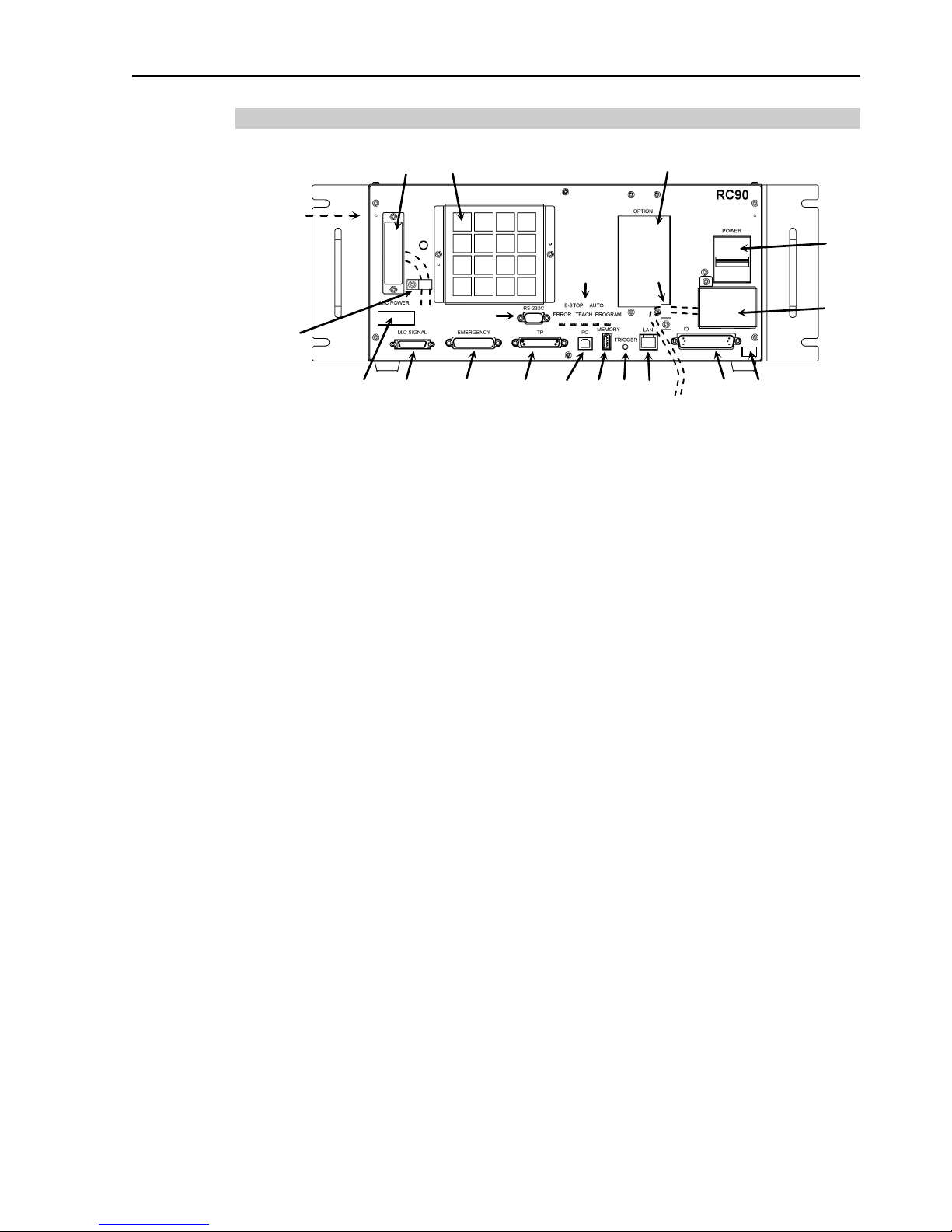
1.3.2 Part Names / Arm Motion
(3)
(19)
(12) (13) (14) (15) (16) (17) (7)
(4)
(1)
(11) (10)
(9)
(20)
(20)
(18)
(5)
(6)
(Left side)
(2)
(8)
(1) POWER switch
(2) AC IN
(3) LED
(4) Fan Filter
(5) Signature label
(6) MT label
(7) Controller Nu mber lab el
(8) Connectio n Check labe l
(9) M/C PO WER connector
(10) M/C SIGNAL connector
(11) EMERGENCY connector
(12) TP port
(13) Development PC connection port
(14) Memory port
(15) Trigg er Switch
(16) LAN (Ethernet communication) port
(17) I/O connector
(18) Standard RS-232C port
(19) Option slot
(20) Cable Clamp
(21) Battery (Mounted inside the controller)
Page 26
1. Safety
10 Safety and Installation (RC90 / EPSON RC+ 7.0) Rev.6
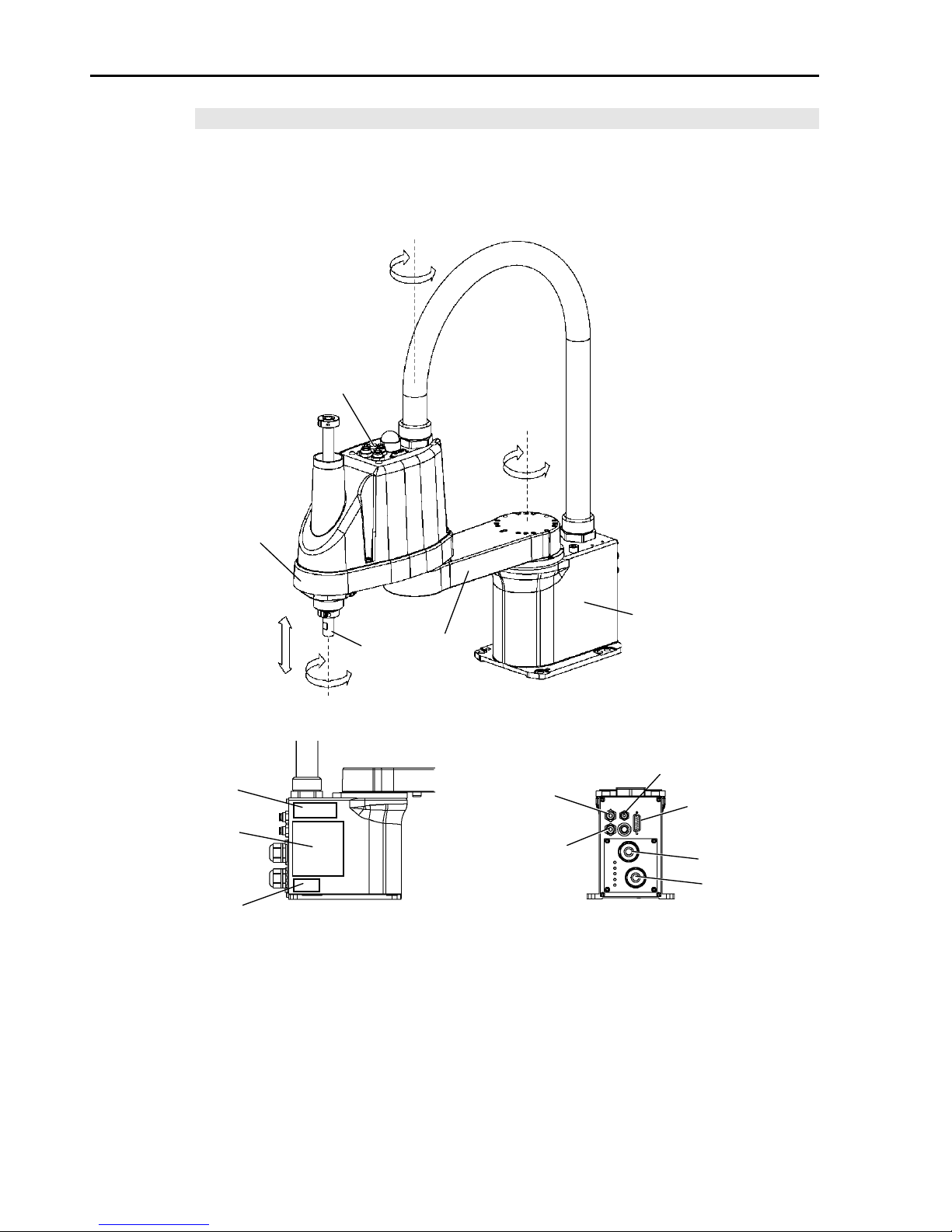
LS3 / LS6
The motion range of each arm is shown in the figure below. Take all
necessary safety precautions.
Joint #3
Brake release switch
Arm #1
Arm #2
Base
Shaft
MT label
(only for custom
specification)
Signature label
(Serial No.
of Manipulator)
Signal cable
Power cable
Fittings (black or blue)
for ø4 mm pneumati c tub e
Fittings (black or blue)
for ø6 mm
pneumatic tube
Fittings (white)
for ø6 mm
pneumatic tube
User connector
(15-pin
D-sub connector)
CE label
+
+
+
+
-
-
-
-
Joint #2
(Rotation)
Joint #1
(Rotation)
Joint #3
(Up/Down)
Joint #4
(Rotation)
Page 27

1. Safety
Safety and Installation (RC90 / EPSON RC+ 7.0) Rev.6 11
When the system is placed in emergency mode, push the arm or joint of
the Manipulator by hand as shown below:
Arm #1 Push the arm by hand.
Arm #2 Push the arm by hand.
Joint #3 The joint cannot be moved up/down by hand until the
solenoid brake applied to the joint has been released.
Move the joint up/down while pressing the brake release
switch.
Joint #4 LS3: Rotate the shaft by hand.
LS6: The shaft cannot be rotated by hand until the
solenoid brake applied to the shaft has been
released. Move the shaft while pressing the
brake release switch.
LS3: The brake release switch affects only Joint #3. When the brake
release switch is p ressed in emergency mode, th e brake for Joint #3
is released.
Be careful of the shaft while the brake release switch is pressed
because the shaft may be lowered by the weight of an end effector.
LS6: The brake release switch affects both Joints #3 and #4. When the
brake release switch is p ress ed in emergen cy mod e, th e b rake for both
Joints #3 and #4 are released simultaneously.
Be careful of the shaft falling and rotating while the brake release
switch is pressed because the shaft may be lowered by the weight of
an end effector.
NOTE
Page 28
1. Safety
12 Safety and Installation (RC90 / EPSON RC+ 7.0) Rev.6
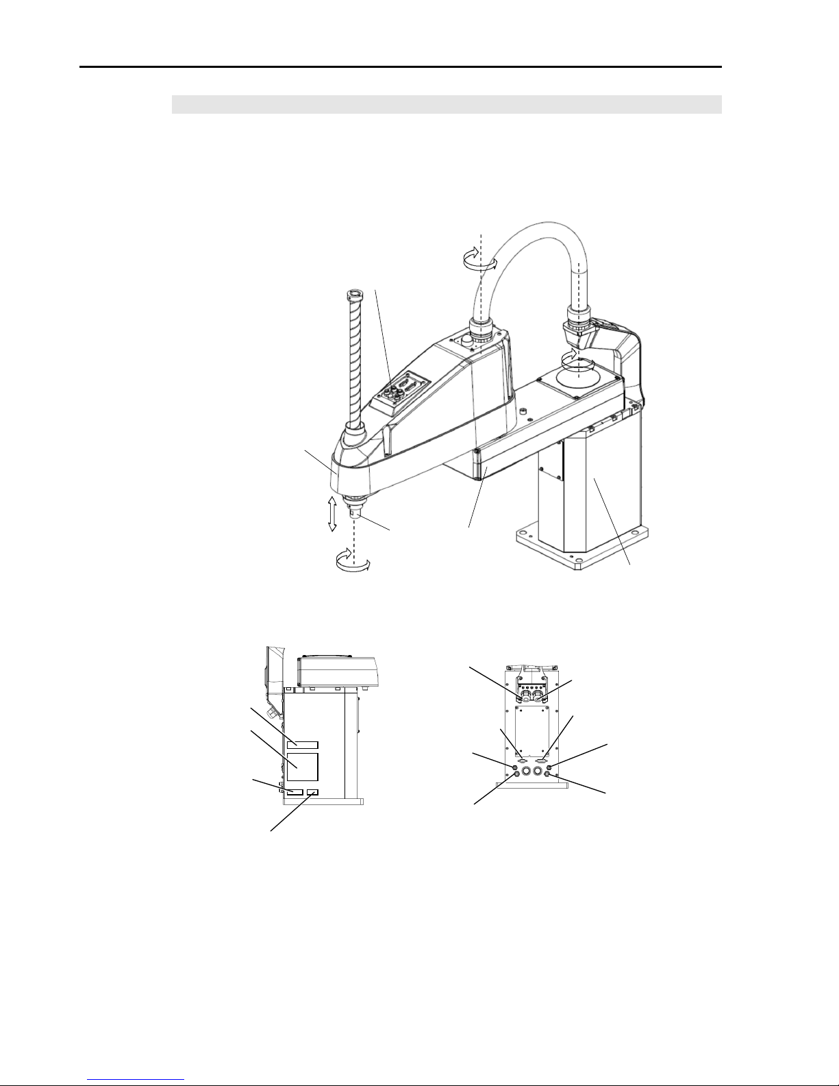
LS20
The motion range of each arm is shown in the figure below. Take all
necessary safety precautions.
Joint #3 / Joint #4
Brake release switch
Joint #1
(Rotation)
Joint #2
(Rotation)
Joint #3
(Up/Down)
Joint #4
(Rotation)
Arm #1
Arm #2
+
-
+
- + -
+
-
Shaft
(Figure: LS20-804S)
Base
MT label
(only for custom
specification)
Signature label
(Serial No.
of Manipulator)
Signal cable
Power cable
Fittings (blue)
for ø4 mm
pneumatic tube
Fittings (blue) for
ø6 mm
pneumatic tube
Fittings (white) fo r
ø6 mm
pneumatic tube
User connector
(15-pin D-sub connector)
CE label
User connector
(9-pin D-sub connector)
Fittings (white) fo r
ø4
mm
pneumatic tube
KC Mark
Page 29

1. Safety
Safety and Installation (RC90 / EPSON RC+ 7.0) Rev.6 13
When the system is placed in emergency mode, push the arm or joint of
the Manipulator by hand as shown below:
Arm #1 Push the arm by hand.
Arm #2 Push the arm by hand.
Joint #3 The joint cannot be moved up/down by hand until the
solenoid brake applied to the joint has been released.
Move the joint up/down while pressing the brake release
switch.
Joint #4 The shaft cannot be rotated by hand until the solenoid
brake applied to the shaft has been released. Move the
shaft while pressing the brake release switch.
The brake release s witch affects both Joints #3 and #4. When the brake
release switch is p ressed in emergency mode, the brakes for both Joints
#3 and #4 are released simultaneously. Be careful of the shaft falling
and rotating while the brake release switch is pressed because the shaft
may be lowered by the weight of an end effector.
NOTE
Page 30

1. Safety
14 Safety and Installation (RC90 / EPSON RC+ 7.0) Rev.6
1.3.3 Operation Modes
The operation mode is defined as the single control point for the controller,
therefore you cannot use more than one ope r a ti on mode at the s am e time .
There are four operation modes for the controller: AUTO, PROGRAM,
TEACH, and TEST.
- AUTO operation modes allow you to execute programs in the
controller when the safeguard is closed.
- PROGRAM operation mode allows you to execute and debug
programs when the safeguard is closed.
- TEACH operation mode allows you to jog and teach the robot at
slow speed while in s ide the safeguarded ar ea.
- TEST operation mode allows you to execute a program at slow speed
while the safeguard is opened.
Page 31

1. Safety
Safety and Installation (RC90 / EPSON RC+ 7.0) Rev.6 15
1.4 Maintenance Safety
Please read this section, Maintenance of the Manipulator manual, Maintenance of
the Controller manual, and other related manuals carefully to understand safe
maintenance pr ocedures before performing any maintenance.
Only authorized personnel who have taken the safety training should be allowed to
maintain the robot system. The safety training is the program for the industrial
robot operator that follows the laws and regulations of each nation.
The personnel who have taken the safety training acquire knowledge of industrial
robots (operations, teaching, etc.), knowledge of inspections, and knowledge of
related rules/regulations. Only personnel who have completed the robot
system-training and maintenance-training classes held by the man ufactu rer, dealer,
or locally-incorporated company shoul d be allowed to maintain the robot system.
WARNING
■
Do not remove any parts that are not covered in th
is manual. Follow
the maintenance procedure strictly as described in this manual
,
Maintenance
of the Manipulator manual, and Maintenance of the
Controller manual
. Improper removal of parts or impro per
maintenance may not only cause impr oper funct ion of th e robot sy stem
but also serious safety problems.
■
Keep away from the Manipulator while
the power is ON if you have not
taken the training courses.
Do not enter the operating area while the
power
is ON. Entering the operating area with the power ON is
extremely hazardous and may cause serious safety problems as the
Manipulator may move
even though it seems to be stopped.
■
When you check the operation of the
Manipulator after replacing parts,
be sure to
check it while you are outside of the safeguarded area.
Checking the operation of the Manipulator while you are inside of the
safeguarded area may cause serious safety problems as the
Manipulator may move unex
pectedly.
■
Before
operating the ro bot system, make sur e tha t both the Emergency
S
top switches and safeguard switches function properly. Operating
the robot system when the switches do not function properly is
extremely hazardous and may result in serious bodily injury and/or
serious damage
to the robot system as the switches cannot fulfill their
intended functions in an emergency.
Page 32

1. Safety
16 Safety and Installation (RC90 / EPSON RC+ 7.0) Rev.6
WARNING
■
Be sure to connect the AC power cable to a power receptacle. DO
NOT connect it directly to a factory power source. To shut off power
to
the robot system, pull out the power plug from the power source.
Performing any work while connecting the A
C power cable to a factory
power source is extremely hazardous and may result in
electr ic shock
and/or malfunction of the robot system.
■
Before
performing any replacement procedure, turn OF F the Controller
and related equipment ,
and then pul l out t h e power plug from the power
source.
Performing any replacement procedure with the power ON is extremely
hazardous and may result in
electric shock and/or malfunction of the
robot system.
■
Be sure to connect the cables properly.
Do not allow unnecessary
strain on the cables.
(Do not put heavy obje cts on the cables. Do not
bend or pull the cables for ci bly.)
The unnecessary strai n on the cables
may result in damage to the cables, disconnection, and/or contact
failure.
Damaged cables, dis connect ion, or contact fa ilure i s ex tremely
hazardous and may result in electric shock and/or improper function of
the robot system.
CAUTION
■
Carefully use
alcohol, liquid gasket, and adhesive following respective
instructions
and also in structi o ns below. Careless use o f alc ohol, liq uid
gasket, or adhesive may cause a fire and/or safety problems.
- Never put alcohol, liquid gasket, or adhesive close to fire.
- Use alcohol, liquid gasket, or adhesive while ventilating the room.
-
Wear protective gear including a mask, protective goggles, and
oil-resistant gloves.
- If alcohol, liquid gas ket, or ad h esive gets on your sk in, wash t he area
thoroughly with soap and water.
- If alcohol, liquid gasket, or adhesive gets into your eyes or mouth,
flush your eyes or wash out your mouth with clean water thoroughly,
and then see a doctor immediately.
Page 33

1. Safety
Safety and Installation (RC90 / EPSON RC+ 7.0) Rev.6 17
CAUTION
■
Wear protective gear inc lud ing a mask, protect iv e goggle s, and
oil
-resistant gloves during grease up. If grease gets into your eyes,
mouth, or on your skin, follow the instructions below.
If grease gets into your eyes:
Flush them thoroughly with clean water, and then see a doctor
immediately.
If grease gets into your mouth:
If swallowed, do not induce vomiting. See a doctor immediately.
If grease just gets into your mouth, wash out your mouth with
water thoroughly.
If grease gets on your skin:
Wash the area thoroughly with soap and water.
Page 34

1. Safety
18 Safety and Installation (RC90 / EPSON RC+ 7.0) Rev.6
1.5 Emergency Stop
Emergency stop motions of the Manipulator vary depending on the controller
firmware. See the section for the Controller firmware of your Control ler.
1.5.1 Free running distance in emergency
Controller Firmware Ver. 7.0.2.3 or earlier
If the Manipulator moves abnormally during operation, immediately press the
Emergency Stop switch. The mot or power will be turned OFF, and t he arm
motion by inertia will be stopped with the electromagnetic brake and dynamic
brake.
However, avoid pressing the Emergency Stop switch unnecessarily while the
Manipulator is running normally. Otherwise, the Manipulator may hit the
peripheral equipment since the operating trajectory while the robot system stops is
different from that in normal operation. It may also result in short life of the
reduction gear u nit due to the shock or the electromagnetic brake du e to the worn
friction plate.
To place the robot system in emergency mode during normal operation, press the
Emergency Stop switch when the Manipulator is not moving.
Refer to the Controller manual for instructions on how to wire the Emergency Stop
switch circuit.
Do not press the Emergency Stop switch unnecessarily while the Manipulator is
operating. Pressing the switch during the operation makes the brakes work.
This will shorten the life of the brakes due to the worn friction plates.
Normal brake life cycle: About 2 years (when the br akes ar e used 100 times/day)
Do not turn OFF the Controller while the Manipulator is operating.
If you attempt to stop the Manipulator in emergency situations such as “Safeguard
Open”, make sure to stop the Manipulator using the E-STOP switch of the
Controller.
If the Manipulator is stopped by turning OFF the Controller while it is operating,
following problems may occur.
Reduction of the life and damage of the reduction gear unit
Position gap at the joints
In addition, if the Controller was forced to be turned OFF by blackouts and the like
while the Manipulator is operating, make sure to check the following points after
power restoration.
Whether or not the reduction gear is damaged
Whether or not the joints are in their proper positions
Page 35

1. Safety
Safety and Installation (RC90 / EPSON RC+ 7.0) Rev.6 19
If there is a position gap, perform calibration by referring to Maintenance:
Calibration in the manipulator manual.
Manipulator manuals contain information on the Emergency Stop. Please also
read the descriptions in the manuals and use the robot system properly.
Before using the Emergency Stop switch, be aware of the followings.
- The Emergency Stop (E-STOP) switch should be used to stop the
Manipulato r only in case of emergencies.
- To stop the Manipulator operating the program except in emergency, use
Pause (halt) or STOP (program stop) commands
Pause and STOP commands do not turn OFF the motors. Therefore, the
brake does not function.
- For the Safeguard system, do not use the circuit for E-STOP.
For details of the Safeguard system, refer to the following manuals.
EPSON RC+ User ’s Guide
2 . Safety - Installation and Design Precautions - Safeguard System
Safety and Installation
2.6 Connection to EMERGENCY Connector
To check brake problems, refer to the following manuals.
Manipulator Manual Maintenance
2.1.2 Inspection Point - Inspection While the Power is ON
(Manipulator is operat i n g)
Safety and Installation
5.1.1 Manipulator - Inspection While the Power is ON
(Manipulator is operat i n g)
Page 36

1. Safety
20 Safety and Installation (RC90 / EPSON RC+ 7.0) Rev.6
The operating Manipulator cannot stop immediately after the Emergency Stop
switch is pressed.
The free running time/angle/distance of the Manipulator are shown below.
However, remember that the values vary depending on following conditions.
Weight of the end effector Weight of work piece Operating pose
Weight Speed Accel etc.
Point where the
emergency stop
signal is input
Joint #1
Start point of
operation
Target point
Stop point
Joint #2
Conditions for Measurement
LS3-401*
LS6-602*
Accel Setting
100
100
Speed Setting
100
100
Load [kg]
3
4
Weight Setting
3
4
Controller
RC90
Manipulator
LS3-401*
LS6-602*
Free running time
Joint #1 + Joint #2 [sec.]
0.4
0.7
Joint #3 [sec.]
0.1
0.2
Free running angle
Joint #1 [deg.]
110
100
Joint #2 [deg.]
20
45
Joint #1 + Joint #2 [deg.]
130
130
Free running distance
Joint #3 [mm]
20
50
Page 37

1. Safety
Safety and Installation (RC90 / EPSON RC+ 7.0) Rev.6 21
Controller Firmware Ver. 7.0.2.4 or later
If the Manipulator moves abnormally during operation, immediately press the
Emergency Stop switch. Pressing the Emergency Stop switch immediately
changes the manipulator to deceleration motion and stops it at the maximum
deceleration s peed.
However, avoid pressing the Emergency Stop switch unnecessarily while the
Manipulator is running normally. Pressing the Emergency Stop switch locks the
brake and it may cause we ar on the friction plate of the brake, resulting in the short
life of the brake.
Normal brake life cycle: About 2 years (when the b rakes are used 100 times/day)
To place the system in emergency mode during normal operation, press the
Emergency Stop switch when the Manipulator is not moving.
Refer to the Controller manual for instructions on how to wire the Emergency Stop
switch circuit.
Do not turn OFF the Controller while the Manipulator is operating.
If you attempt to stop the Manipulator in emergency situations such as “Safeguard
Open”, make sure to stop the Manipulator using the Emergency Stop switch of the
Controller.
If the Manipulator is stopped by turning OFF the Controller while it is operating,
following problems may occur.
Reduction of the life and damage of the reduction gear unit
Position gap at the joints
In addition, if the Controller was forced to be turned OFF by blackouts and the like
while the Manipulator is operating, make sure t o check the following points after
power restoration.
Whether or not the reduction gear is damaged
Whether or not the joints are in their proper positions
If there is a position gap, perform calibration by referring to the Maintenance 13.
Calibration in this manual.
Before using the Emergency Stop switch, be aware of the followings.
- The Emergency Stop (E-STOP) switch should be used to stop the
Manipulato r only in case of emergencies.
- To stop the Manipulator operating the program except in emergency, use
Pause (halt) or STOP (program stop) commands
Pause and STOP commands do not turn OFF the motors. Therefore, the
brake does not function.
- For the Safeguard system, do not use the circuit for E-STOP.
Page 38

1. Safety
22 Safety and Installation (RC90 / EPSON RC+ 7.0) Rev.6
For details of the Safeguard system, refer to the following manuals.
EPSON RC+ User ’s Guide
2 . Safety - Installation and Design Precautions - Safeguard System
Safety and Installation
2.6 Connection to EMERGENCY Connector
To check brake problems, refer to the following manuals.
Manipulator Manual Maintenance
2.1.2 Inspection Point - Inspection While the Power is ON
(Manipulator is operat i n g)
Safety and Installation
5.1.1 Manipulator - Inspection While the Power is ON
(Manipulator is operat i n g)
Free running distance in emergency
The operating M anipulator cannot stop immedi ately after the Emergency Stop
switch is pressed.
The free running time/angle/distance of the Manipulator are shown below.
However, remember that the values vary depending on following conditions.
Weight of the end effector Weight of work piece Operating pose
Weight Speed Accel etc.
Page 39

1. Safety
Safety and Installation (RC90 / EPSON RC+ 7.0) Rev.6 23
LS3 / LS6
Conditions for
Measurement
LS3-401* LS6-502*, 602*, 702*
Accel Setting
100
100
Speed Setting
100 100
Load [kg]
3 6
Weight Setting
3
6
Joint #1
Joint #2
Stop point
Point where the
emergency stop
signal is input
Target point
Start point of
operation
Controller RC90
Manipulator LS3-401* LS6-502* LS6-602* LS6-702*
Free running
time
Joint #1 + Joint #2 [sec.] 0.4 0.4 0.7 0.7
Joint #3 [sec.] 0.1 0.2
Free running
angle
Joint #1 [deg.] 110 42 100 85
Joint #2 [deg.] 20 42 45 50
Joint #1 + Joint #2 [deg.] 130 84 130 135
Free running
distance
Joint #3 [mm] 20 90
Page 40

1. Safety
24 Safety and Installation (RC90 / EPSON RC+ 7.0) Rev.6
LS20
Conditions for
Measurement
LS20-804*
LS20
-A04*
Accel Setting
100
100
Speed Setting
100
100
Load [kg]
20
20
Weight Setting
20
20
Joint #1
Stop point
Point where the
emergency stop
signal is input
Target point
Start point of
operation
Joint #2
Controller RC90
Manipulator LS20-804* LS20-A04*
Free running time
Joint #1 + Joint #2 [sec.] 0.65 0.7
Joint #3 [sec.] 0.3
Free running angle
Joint #1 [deg.] 65 70
Joint #2 [deg.] 50 50
Joint #1 + Joint #2 [deg.] 115 120
Free running distance Joint #3 [mm] 110
Page 41

1. Safety
Safety and Installation (RC90 / EPSON RC+ 7.0) Rev.6 25
1.5.2 How to Reset the Emergency Mode
Select EPSON RC+ [Tools] – [Robot Manager] – [Control Panel] tab, and then
click <Reset>.
The Control Panel page contains buttons for basic robot operations, such as
turning motors on/off and homing the robot. It also shows status for Emergency
Stop, Safeguard, Motors, and Power.
Page 42

1. Safety
26 Safety and Installation (RC90 / EPSON RC+ 7.0) Rev.6
1.6 Labels
Labels are attached around the locations of the Controller and Manipulator where
specific dangers exi st.
Be sure to comply with descriptions and warnings on the labels to operate and
maintain the Robot System safely.
Do not tear, damage, or remove the labels. Use meticulous care when handling
those parts or units to which the following labels are attached as well as the nearby
areas:
1.6.1 Controller
Location
Label
Note
A
Residual voltage exists. To avoid
electric shock, do not open the cover
while the Power is ON, or for 300
seconds after the Power is OFF.
B
Disconnect and lockout main power
before performing maintenance and
repair.
C
TP port of RC90 is for the Teach Pendant
TP1 and TP2. Do not connect the
followings to TP port of RC90.
Connecting to the followings may result in
malfunction of the device.
OPTIONAL DEVICE dummy plug,
OP500, OP500RC, JP50 0, T P -3** seri es,
and OP1
Refer to 4.3 Connection of Option
Teaching Pendant.
A
C
B
Page 43

1. Safety
Safety and Installation (RC90 / EPSON RC+ 7.0) Rev.6 27
1.6.2 Manipulator
Location
Label
Note
A
Before lo
osening the base mounting
screws, hold the arm a nd secu re it tig htly
with a band to prevent hands or fingers
from being caught in the Manipulator.
For installation and transportation of
robots
, follow the directions in this
manual.
B
Do not enter the opera tion ar ea w hile the
Manipulator is moving. The robot arm
may collide against the operator. This
is extremely hazardous and may result
in serious safety problems.
C
Hazardous voltage exists while the
Manipulator is ON. To avoid electric
shock, do not touch any internal electric
parts.
D
You can catch your hand or fingers
between the shaft and cover when
bringing your hand close to moving
parts.
Manipulators with bellows do not have
this label for no danger of your hand or
fingers being caught
E
Only authorized personnel should
perform sling work and operate a crane
and a forklift. When these operations
are performed
by unauthorized
personnel, it is extremely haz a rdous and
may result in serious bodily injury and/or
severe equipment damage to the robot
system.
Page 44

1. Safety
28 Safety and Installation (RC90 / EPSON RC+ 7.0) Rev.6
Location
Label
Note
F
Be careful of the
shaft falling and
rotating while the brake release switch
is pressed because
the shaft may be
lowered by the weight of the end
effector.
Page 45

1. Safety
Safety and Installation (RC90 / EPSON RC+ 7.0) Rev.6 29
LS3
C
A
D
B
C
(Figure: LS3-401S)
LS6
C (Arm #1 Cover)
A
D
B
C
(Figure: LS6-602S)
Page 46

1. Safety
30 Safety and Installation (RC90 / EPSON RC+ 7.0) Rev.6
LS20
C A D
B
C
E
(Opposite side)
F
(Figure: LS20-804S)
Page 47

1. Safety
Safety and Installation (RC90 / EPSON RC+ 7.0) Rev.6 31
1.7 Safety Features
The robot control system supports safety features described below. However, the
user is recommended to strictly follow the proper usage of the robot system by
thoroughly readi ng the attach ed manuals befo re using the system. Fai lure to read
and understand the proper usage of the safety functions is highly dangerous.
Among the following safety features, the Emergency Stop Switch and Safety Door
Input are particu larly importan t. Make sure that these and other featur es functio n
properly before operating the robot system.
For details, refer to the 2.5 Controller Installation - Safety Door Swit ch and La tch
Release Switch.
Emergency Stop Switch
The EMERGENCY connector on the Controller has expansion Emergency Stop
input terminals used for connecting the Emergency Stop switches.
Pressing any Emergency Stop switch can shut off the motor power immediately
and the robot system will enter the Emergency Stop condition.
Safety Door Input
In order to activate this feature, make sure that the Safety Door Input switch is
connected to the EMERGENCY connector at the Controller.
When the safety door is opened, normally the Manipulator immediately stops the
current operation, and the status of Manipulator power is operation-prohibited
until the safety door is closed and the latched condition is released. In order to
execute the Mani pulator operation while the safety door is open, you must change
the mode selector key switch on the Teach Pendant to the “Teach” mode.
Manipulator operation is available only when the enable switch is on. In this
case, the Manipulator is operated in low power status.
Page 48

1. Safety
32 Safety and Installation (RC90 / EPSON RC+ 7.0) Rev.6
Low Power Mode
The motor power is reduced in this mode.
Executing a power status change instruction will change to the restricted (low
power) status regardless of conditions of the safety door or operation mode. The
restricted (lo w power)
status ensures the safety of the operator and reduces the
possibility of peripheral equipment destruction or damage caused by careless
operation.
Dynamic Brake
The dynamic brake circuit includes relays that short the motor armatures. The
dynamic brake circuit is activated when t here is an Emergenc y Stop input or when
any of the following errors is detected: encoder cable disconnection, motor
overload, irregular motor torque, motor speed error, servo error (positioning or
speed overflo w), irregular CPU, me mory check-sum erro r and overheat condition
inside the Motor Driver Module.
Motor Overload Detection
The dynamic brake circuit is activated when the system detects that the load on the
motor has exceeded its capacity.
Irregular Motor Torque (out-of-contr ol mani pul ator ) Det ec tion
The dynamic brake circuit is activated when irregularity with motor torque (motor
output) is detected (in which case the Manipulator is out of contro l).
Motor Speed Error Detection
The dynamic brake ci rcuit is activated when the system detects that th e motor is
running at incorrect speed.
Positioning Overflow -Servo Error- Detection
The dynamic brake circuit is activated when the syste m detects that t he difference
between the Manipulator’s actual position and commanded position exceeds the
margin of error allowed.
Speed Overflow -Servo Error- Detection
The dynamic brake circuit is activated when the Manipulator’s actual speed is
detected to mark an overflow (the actual sp eed is outside the nominal range) er ror.
Page 49

1. Safety
Safety and Installation (RC90 / EPSON RC+ 7.0) Rev.6 33
CPU Irregularity Detection
Irregularity of CPU that controls the motor is detected by the watchdog timer.
The system CPU and the motor controlling CPU inside the Controller are also
designed to const antly check each o ther for any discr epan cies. If a discrepancy is
detected, th e dynamic brake circuit is activated.
Memory Check-sum Error Detection
The dynamic brake circuit is activated when a memory check-sum error is
detected.
Overheat Detection at the Motor Driver Module
The dynamic brake circuit is activated when the temperature o f the power device
inside the Motor Driver module is above the nominal limit.
Relay Deposition Detection
The dynamic brake circuit is activated when relay deposition is detected.
Over-Voltage Detection
The dynamic brake circuit is activated when the voltage of the Controller is above
the normal limit.
AC Power Supply Voltage Drop Detection
The dynamic bra ke circuit is a ctivated when the drop of the power supply voltage
is detected.
Temperature Anomaly Detection
The temperature an omaly is detected.
Fan Malfunction Detection
Malfunction of the fan rotation speed is detected.
Page 50

1. Safety
34 Safety and Installation (RC90 / EPSON RC+ 7.0) Rev.6
1.8 Lockout / Tagout
Lockout / tagout is a method to prevent anyone from turning ON the robot system
by mistake while so meone else is within the safeguarded area for maintenance o r
repair.
When performing maintenance and repair, lockout and tagout using the following
procedure. Use the lockout attachment for RC90.
Installing the Lockout Attachment
(1) Turn OFF the POWER switch and place the lockout attachment on the
POWER switch.
Insert the pin in t he hole s unde r the retractable actuator.
Push the pin in the
direction of arrows, and
insert the pin in the holes.
POWER
switch
Lockout
Attachment
Hole
Pin
(2) Turn the lockout
attachment.
(3) Install the lockout
attachment on the switch.
(4) Slide the pin to
the lock position.
Lock position
Page 51

1. Safety
Safety and Installation (RC90 / EPSON RC+ 7.0) Rev.6 35
Padlock Size and Weight
The padlock is not supplied with the lockout attachment and must be supplied by
the user.
The total weight of the padlock can be a maximum of 45 g.
Make sure the padlock weight does not exceed 45 g, otherwise th e POWER switch
may be damaged.
Applicable Padlock
Safety Precautions
When using the padlock, do not use the controller where it is subject to vibration
or shock, oth er wise failure or damage may result.
Do not apply a force of more than 50N on the lockout attachment; otherwise the
lockout attachment will be damaged.
Page 52

1. Safety
36 Safety and Installation (RC90 / EPSON RC+ 7.0) Rev.6
1.9 Manipulator Specifications
LS3 / LS6
Item
LS3-401*
LS6-602*
Arm length
Arm # 1, #2 400 mm
50
500 mm
60
600 mm
70
700 mm
Arm # 1 225 mm
50 225 mm
60
325 mm
70 425 mm
Arm # 2
175 mm
275 mm
Max.
operating speed
*1
Joints #1, #2 6000 mm/s
50
6150 mm/s
60
6800 mm/s
70 7450 mm/s
Joint #3 1100 mm/s
Joint #4
2600 deg./s
2000 deg/s
Repeatability
Joints #1, #2
± 0.01 mm
± 0.02 mm
Joint #3 ± 0.01 mm
Joint #4
±
0.01 deg.
Payload (Load)
Rated
1 kg
2 kg
Max.
3 kg
6 kg
Joint #4 allowable
moment of inertia
*2
Rated
0.005 kg· m2
0.01 kg·m2
Max.
0.05 kg·m2
0.12 kg·m2
Resolution
Joint #1
0.00043 9 deg./pulse
0.00027 5 deg/pulse
Joint #2
0.00043 9 deg./pulse
Joint #3
0.000799 mm/pulse
0.000814 mm/pulse
Joint #4
0.00192 7 deg./pulse
0.00146 5 deg/pulse
Hand
Shaft diameter
ø 16 mm
ø 20 mm
Through hole
ø 11 mm
ø 14 mm
Mounting hole
120 × 120 mm / 135 × 120 mm
(Free choice of either hole.)
150 × 150 m m
4-M8
Weight (cables not included)
14 kg : 31 lb
50
17 kg : 37.5 lb
60
17 kg : 37.5 lb
70
18 kg : 39.7 lb
Driving method
All joints
AC servo motor
Page 53

1. Safety
Safety and Installation (RC90 / EPSON RC+ 7.0) Rev.6 37
Item
LS3-401*
LS6-602*
Motor
energy consumption
Joint #1
200 W
Joint #2
100 W
200 W
Joint #3 100 W
Joint #4
100 W
Option
Installation
environment
Cleanroom *3
Joint #3 down force
100 N
Installed wire for customer use 15 (15 pin: D-sub)
Installed pneumatic
tube for customer use
2 pneumatic tubes (ø6 mm) : 0.59 Mpa (6 kgf/cm2 : 86 psi)
1 pneumatic tubes (ø4 mm) : 0.59 Mpa (6 kgf/cm2 : 86 psi)
Environmental
requirements
Ambient Temp. 5 to 40 degrees C (with minimum temperature variation)
Ambient relative
humidity
10 to 80% (no condensation )
Noise level *4
L
Aeq
= 70 dB (A)
Applicab le Controller
RC90
Assig nable Value
( ) Default values
SPEED
1 to (5) to100
ACCEL *5
1 to (10) to 120
SPEEDS
1 to (50) to 2000
ACCELS
1 to (200) to 25000
FINE 0 to (1250) to 65000
WEIGHT
0,175 to (1,175) to 3,175
0,275 to (2,275) to 6,275
Safety standard
CE Mark
EMC Directive
Machinery Directive
RoHS Directive
KC Mark / KCs Mark
Item
LS3-401S
LS3-401C
LS6-**2S
LS6**02C
Max.
motion
range
Joint #1
± 132 deg
Joint #2
± 141 deg
± 150 deg
Joint #3
150 mm
120 mm
200 mm
170 mm
Joint #4
± 360 deg
Max.
pulse
range
Joint #1
- 95574~505174 pulse
- 152918~808278 pulse
Joint #2
± 320854 pulse
± 341334 pulse
Joint #3
-187734~ 0 pulse
-150187~ 0 pulse
-245760~ 0 pulse
-208896~0 pulse
Joint #4
± 186778 pulse
± 245760 pulse
Page 54

1. Safety
38 Safety and Installation (RC90 / EPSON RC+ 7.0) Rev.6
LS20
Item LS20-804* LS20-A04*
Arm length
Arm # 1, #2
800 mm
1000 mm
Arm # 1 350 mm 550 mm
Arm # 2
450 mm
450 mm
Max.
operating speed
*1
Joints #1, #2
9940 mm/s
11250 mm/s
Joint #3
2020 mm/s
Joint #4
1400 deg/s
Repeatability
Joints #1, #2
±
0.025 mm
Joint #3
±
0.01 mm
Joint #4
± 0.01 deg
Payload (Load)
Rated
10 kg
Max.
20 kg
Joint #4 allowable
moment of inertia *2
Rated
0.05 kg·m2
Max.
0.45 kg·m2
Resolution
Joints #1
0.00027 5 deg/pulse
Joint #2
0.00043 9 deg/pulse
Joint #3
0.00148 mm/pulse
Joint #4
0.00104 6 deg/pulse
Hand
Shaft diameter
ø 25 mm
Through hole
ø 18 mm
Mounting hole
200 × 200 mm
4 × ø16
Weight (cables not included)
47 kg : 103.6 lb
50 kg : 110.2 lb
Driving method
All joints
AC servo motor
Motor
energy consumption
Joint #1
750 W
Joint #2 600 W
Joint #3
400 W
Joint #4
150 W
Option
Installation environment
Cleanroom *3
Joint #3 down force
250 N
Installed wire for customer use
15 pin: D-sub, 9 pin: D-sub
Installed pneumatic
tube for customer use
2 pneumatic tubes (ø6 mm) : 0.59 Mpa (6 kgf/cm2 : 86 psi)
2 pneumatic tubes (ø4 mm) : 0.59 Mpa (6 kgf/cm2 : 86 psi)
Page 55

1. Safety
Safety and Installation (RC90 / EPSON RC+ 7.0) Rev.6 39
Item LS20-804* LS20-A04*
Environmental
requirements
Ambient Temp.
5 to 40 °C (with minimum temperature variation)
Ambient relative humidity
10 to 80 % (no condensation)
Noise level *4
L
Aeq
= 70 dB (A)
Applicab le Controller RC90
Assig nable Value
( ) Default values
Speed
1 to (5) to 100
Accel *5
1 to (10) to 120
SpeedS
1 to (50) to 2,000
AccelS
1 to (200) to 10,000
Fine
0 to (1,250) to 65,000
Weight
0,450 to (10,450) to 20,450
Safety standard
CE Mark
EMC Directive
Machinery Directive
RoHS Directive
KC Mark / KCs Mark
Item
LS20-804S
LS20-A04S
LS20-804C
LS20-A04C
Max.
motion range
Joint #1
± 132 deg
Joint #2
± 152 deg
Joint #3
420 mm
390 mm
Joint #4
± 360 deg
Max.
pulse range
Joint #1
- 152918 to 808278
Joint #2
± 345885
Joint #3
-283853 to 0
-263578 to 0
Joint #4
± 344064
Page 56

1. Safety
40 Safety and Installation (RC90 / EPSON RC+ 7.0) Rev.6
*1: In the case of PTP command.
Maximum operating speed for CP command is 2000 mm/s on horizontal plane.
*2: In the case where the center of gravity is at the center of Joint #4.
If the center of gravity is not at the center of Joint #4, set the parameter using Inertia
command.
*3: The exhaust system in the Cleanroom-model Manipulator draws air from the base interior
and arm cover interi or together.
A crack or other openi ng in the base unit can cause loss o f negative air p ressure in th e outer
part of the arm, which can cause increased dust emission.
Seal the exhaust port and the exhaust tube with vinyl tape so that the joint is airtight.
If the exhaust flow is not sufficient, dust particle emission may exceed the specified
maximum level.
Cleanliness level : Class ISO 4 (ISO14644-1)
Exhaust System : Exhaust port diameter: Inner diameter: ø12 mm /
Outer diameter: ø16 mm
Exhaust tube : Polyurethane tube
Outer diameter: ø12 mm (Inner diameter: ø8
mm) or Inner diamet e r ø16 mm
Recommended exhaust flow rate:
approx. 1000 cm
3
/s (Normal)
*4: Conditions of Manipulator during measurement as follows:
Operating conditions : Under rated load, 4-joints simultaneous motion, maximum
speed, maximum acceleration, and dut y 50%.
Measurement point : In front of the Manipulator, 1000 mm apart from the motion
range, 50 mm above the base-installed surface.
*5: In general use, Accel setting 100 is the optimum setting that maintains the balance of
acceleration and vibration when positioning. Although values larger than 100 can be set to
Accel, it is recommended to minimize the use of large values to necessary motions since
operating the manipulator continuously with the large Accel setting may short en the prod u ct
life remarkably.
Page 57

1. Safety
Safety and Installation (RC90 / EPSON RC+ 7.0) Rev.6 41
1.10 Motion Range Setting by Mechanical Stops
Mechanical stops physically l imit the absolute area that the Manipulator can move.
Both Joints #1 and #2 have threaded holes in the positions corresponding to the
angle for the mechanical stop settings. Install the bolts in the holes
corresponding to the angle that you want to set.
Joints #3 can be set to any length less than the maxi mum stroke.
LS3 / LS6
Mechanical stop of Joint #2
(Fixed)
Mechanical stop of
Joint #1 (Adjustable)
Mechanical stop of Joint #3
(Lower limit mechanical stop)
(Do not move the upper
limit mechanical stop.)
Mechanical stop of
Joint #1 (Fixed)
Mechanical stop of
Joint #2 (Adjustable)
LS20
Mechanical stop of Joint #2
(Fixed)
Mechanical stop of
Joint #1 (Adjustable)
Mechanical stop of Joint #3
(Lower limit mechanical stop)
(Do not move th e upper
limit mechanical stop.)
Mechanical stop of
Joint #1 (Fixed)
Mechanical stop of
Joint #2 (Adjustable)
Page 58

1. Safety
42 Safety and Installation (RC90 / EPSON RC+ 7.0) Rev.6
1.11 End User Training
Be sure those in charge of safety management confirm that the operators who
program, operate, and maintain the robot and robot system obtain proper training
and have the exper tise to conduct the work sa fely.
Training should include at least the following:
- Study of regulation safety procedures, and safety-related recommendations by
robot manufacturers and system designers.
- Clear explanation of the work involved.
- Description of all control equipment required for the work and their functions.
- Explanation of potential hazards involved in the work.
- Work safety procedures and specific methods of avoiding potential hazards.
- Safety device and interlock function testing and confirmation methods are
working properly.
Page 59

2. Installation
Safety and Installation (RC90 / EPSON RC+ 7.0) Rev.6
43
2. Installation
This chapter contains precautions for safe and accurate installation of the robot
system.
The outline to install the robot system is indicated on 2.1 Outline from Unpacking
to Operation of Robot System. Refer to each section and/or the Manipulator
manual and the Controller manual for unpacking, transportation, and installation.
Page 60

2. Installation
Safety and Installation (RC90 / EPSON RC+ 7.0) Rev.6
44
System Example
*1 EPSON RC+ 7.0 supports the following OS
Windows XP Professional Service Pack 3
Windows Vista Business Service Pack 2
Windows 7 Professional
Windows 8.1 Pro (EPSON RC+7.0 Ver.7.1.0 or later)
Operation panel
Motion Controller
RC90
Expansion I/O Bo a rd
Fieldbus
PROFIBUS-DP
DeviceNet
CC-Link
EtherNet/IP
PROFINET
EtherCAT
RS-232C Board
Windows *1
PC
EPSON RC+ 7.0
Software
Option
USB 2.0
or
Ethernet
TP2
(Option)
Standard I/O
Remote I/O
Ethernet
RS-232C
Requires preparation
by users
LS series
PLC (Sequencer)
Option
Standard
PG Board
TP1
(Option)
Page 61

2. Installation
Safety and Installation (RC90 / EPSON RC+ 7.0) Rev.6
45
2.1 Outline from Unpacking to Operation of Robot System
Transportation
Unpacking
Error?
Installation
Power-on
Yes
No
Procedures to install EPSON RC+5.0
to the development PC and enable the
operation of the robot system
Manual information to connect or
setup the equipment and options
2. Installation
Procedures to install the Robot system
and turn ON the power properly
4. Second Step
3. First Step
Page 62

2. Installation
Safety and Installation (RC90 / EPSON RC+ 7.0) Rev.6
46
2.2 Unpacking
Installation and transportation of robots and robotic equipment shall be performed
by qualified personnel and should conform to all national and local codes.
Using a cart or similar equipment, transport the Manipulator in the same
conditions as it was delivered. Observe the following when unpacking the
Manipulator.
2.2.1 Package Compone nts Ex ample
The following figure illustrates the package at delivery.
Manipulator
Controller etc.
Attached Equipment
2.2.2 Unpacking Precautions
T ransportation proc e dure
: Only authorized personnel should
perform sling work and operate a crane or
forklift. When these operations are p erformed
by unauthorized personnel, it
is extremely
hazardous and may result in serious bodily injury and/or severe
equipment damage to the robot system.
V ibrati on at transporta tion
: Avoid excessive vibration or shock during Manipulator transporting.
Excessive vibration or shock may cause equipment d
amage to and/or
malfunction of the Manipulator.
Anchor bolt
: When removing the anchor bolts, support the Manipulator to prevent falling.
Removing the anchor bolts without supporting the Manipulator may get
hands, fingers, o r feet caught as the Manipulator will fall.
Wire tie
: Do not remove the wire t ie securing the arm until you finish the installation.
You may get your hands caught in the Manipulator when the wire tie is
removed before completing the installation.
Page 63

2. Installation
Safety and Installation (RC90 / EPSON RC+ 7.0) Rev.6
47
2.3 Transportation
Installation and transportation of robots and robotic equipment shall be performed
by qualified personnel and should conform to all national and local codes.
2.3.1 Transportation Precautions
Transporta ti on proc edure
: Using a cart or similar
equipment, transport the Manipulator in the same
conditions as it was delivered. Observe the following when unpacking
the Manipulator.
Only authorized personnel should perform sling work and operate a crane
or forklift. When these operations are performed
by unauthorized
personnel, it is extremely
hazardous and may result in serious bodily
injury and/or severe equipment damage to the robot system.
Vibration at transportation
: Avoid excessive vibration or shock during Manipulator transporting.
Excessive vibration or shock may cause equipment damage to and/or
malfunction of the Manipulator.
Anchor bolt
:
When removing the anchor bolts, support the Manipulator to prevent
falling.
Removing the anchor bolts without supporting the Manipulator may get
hands, fingers, or feet caught as the Manipulator will fall.
Wire tie
: Do not remove the wire tie securing the arm until you
finish the
installation.
You may get your hands caught in the Manipulator when the wire tie is
removed before completing the installation.
Hoisting procedure
: Stabilize the Manipulator with your hands when hoisting it. Unstable
hoisting is extremely hazardous and may results in serious bodily injury
and/or sever
e equipment damage to the robot system as the fall of the
Manipulator.
Page 64

2. Installation
Safety and Installation (RC90 / EPSON RC+ 7.0) Rev.6
48
2.3.2 Manipulator Transportation
LS3 / LS6
To carry the Manipulator, have two or more people to work on it and secure the
Manipulator to the delivery equipment or hold the areas indicated in gray in the
figure (bottom of Arm #1 and bottom of the base) by hand.
When holding the bottom of the base by hand, be very careful not to get your
hands or fingers caught.
LS3
-401* : approx. 14 kg: 31 lb.
LS6
-502* : approx. 17 kg :37.5 lb.
LS3-602* : approx. 17 kg: 37.5 lb.
LS6-702* : approx. 18 kg :39.7 lb.
Page 65

2. Installation
Safety and Installation (RC90 / EPSON RC+ 7.0) Rev.6
49
LS20
To carry the Manipulator, secure it to the delivery equipment or pass a belt through
the eyebolt to hang the Manipulator, and then attach the hands on the shaded area
in the figure below (bottom of the Arm #1 and the base). If carrying the
Manipulator without using the belt, have at least four workers to work on it.
When holding the bottom of the base by hand, be very careful not to get your
hands or fingers caught.
Do not hold the metal duct and the resin duct when carrying the Manipulator. It
may damage them.
(
Figure : LS20-804S)
LS20-804* : approx. 47 kg :103.6 lb.
LS20-A04* : approx.
50 kg :
110.2 lb.
Resin duct
Metal duct
Page 66

2. Installation
Safety and Installation (RC90 / EPSON RC+ 7.0) Rev.6
50
(1) Attach the eyebolts to the upper back side of the Arm.
(2) Turn the Arm #1 to face the front.
(3) Fix the Arm #1 using the arm lock so that it cannot move.
(4) Use the wire tie to fix the band for hoisting to the Arm #1. Set the band at
the shaded area in th e figure below so that the ban d cannot move.
(5) Pass the belts through the eyebolts.
(6) Hoist the Manipulator slightly so that it does not fall. Then, remove the
bolts securing the Manipulator to the delivery equipment or pallet.
(7) Hoist the Manipulator attaching the hands on the shaded area so that it can
keep the balance. Then, move it to the base table.
Arm #1
Band fixing
position
Arm Lock
Page 67

2. Installation
Safety and Installation (RC90 / EPSON RC+ 7.0) Rev.6
51
2.4 Manipulator Installation
Installation and transportation of robots and robotic equipment shall be performed
by qualified personnel and should conform to all national and local codes.
2.4.1 Installation Precautions
Safeguard installation
: To ensure safety, a safeguard must be installed for the robot system.
For details on the safeguard, refer to the
Installation and Design
Precautions in the Safety chapter of the EPSON RC+ User’s Guide.
Space between safeguard and Manipulator
: Install the Manipulator at a location with sufficient space so that a tool or
a work piece on the end effector does not reach a wall or a safeguard
when the Manipulator extends
its arm fully while holding a work piece.
Installing the Manipulator at a location with insufficient
space is
extremely
hazardous and may result in serious bodily injury and/or
severe equipment damage to the robot system as a tool or a work p iece
may collide with a wall and a safeguard.
Manipulator check before installation
: Before install ing and operatin g the Manipulator, make sure that all parts
of the Manipul ator are in place and h ave no external defects. Missing
or defective parts may cause improper operation of the Manipulator
.
Improper operation of the Manipulator is extremely hazardous and may
result in serious bodily injury and/or severe equipment damage to the
robot system.
2.4.2 Environment
In order to optimize the robot system’s perfo r mance for sa fet y, the Controller must
be placed in an environment that satisfies the following conditions:
- The Controller is not designed for clean-room specification. If it
must be installed in a clean room, be sure to install it in a proper
enclosure with adequate ventilation and cooling.
- Install Controller in a location that allows easy connection /
disconnection of cables.
NOTE
Page 68

2. Installation
Safety and Installation (RC90 / EPSON RC+ 7.0) Rev.6
52
Item
Condition
Ambient temperature
5 to 40 deg.C (with minimal variation)
Ambient relative humidity
20% to 80% (with no condensation)
First transient burst noise 2 kV or less (Power supply wire)
1 kV or les (Signal wire)
Electrostatic noise
4 kV or less
Base table Use a base table t hat is at least 100 mm off the
floor. Placing the Controller directly on the
floor could allow dust penetration leading to
malfunction.
2.4.3 Noise level
Noise level by movement of manipulator.
LS series: LAeq = 70 dB (A)
Operating conditions
Under rated load, 4-joints simultaneous motion, maximum speed, maximum
acceleration , and duty 50%.
Measurement point
In front of the Manipulator, 1000 mm apart from the motion range, 50 mm
above the base-installed surface.
Page 69

2. Installation
Safety and Installation (RC90 / EPSON RC+ 7.0) Rev.6
53
2.4.4 Base Table
A base table for anchoring the Manipulator is not supplied. Please make or
obtain the base tab le for your Manipulator. The shape and size o f the base table
differs depending on the use of the robot system. For your reference, we list
some Manipulator table requirements here.
The torque and reaction force produced by the movement of the Manipulator are
as follows:
LS3
LS6
LS20
Max. Reaction torque
on the horizontal plate
250
Nm
350
Nm
1000 Nm
Max. Horizon tal reaction force
1000
N
1700
N
7500
N
Max. Vertical r eaction force
1000 N 1500 N 2000 N
The threaded holes required for mounting the Manipulator base are LS3/LS6: M8,
LS20: M12. Use mounting bolts with specifications conforming to ISO898-1
property class: 10.9 or 12.9.
The plate for the Manipulator mounting face should be 20 mm thick or more and
made of steel to r edu ce vib ratio n. The surface roughness of the steel plate should
be 25 μm or less.
The table must be secured on the floor or wall to prevent it from moving.
The Manipulator must be installed horizontally.
When using a leveler t o adjust the heigh t of the base tab le, use a screw with M16
diameter.
Page 70

2. Installation
Safety and Installation (RC90 / EPSON RC+ 7.0) Rev.6
54
2.4.5 Installation Procedure
When the Manipul ator is Clean-model, unpack it outside of the clean room.
Secure the Manipulator not to fall, and then wipe off the dust on the
Manipulator with a little alcohol or distilled water on a lint-free cloth. After
that, carry the Manipulator in the clean ro om. Connect an exhaust tube to
the exhaust port after installation.
LS3 / LS6
CAUTION
■
Install the
LS3 / LS6 series Manipulator with two or more people.
The Manipulator weigh
ts are as follows. Be careful not to get
hands,
fingers, or feet caught and/or have equipment damaged by
a
fall of the Manipulator.
LS3-401* : approx. 14 kg: 31 lb.
LS6-502* : approx. 17 kg :37.5 lb.
LS6-602* : approx. 17 kg: 37.5 lb.
LS6-702* : approx. 18 kg :39.7 lb.
(1)
Secure the base to the
base
table with four bo
lts.
Use bolts
with specifications
conforming
to ISO898-1
P
roperty Class: 10.9 or 12.9.
Tightening torque:
32.0 N·m (326 kgf·cm)
4-M8×25
Screw Hole
(depth 20 mm
or more)
Spring
Washer
Plane
Washer
NOTE
NOTE
Page 71

2. Installation
Safety and Installation (RC90 / EPSON RC+ 7.0) Rev.6
55
LS6
only
(2)
Using nippers, cut off the wire tie
binding
the shaft and arm retaining
bracket on the
base.
Bolt
M4×20
Wire tie
Bolt
M4×20
LS6
only
(3)
Remove the bolts securing the wire
ties removed in step (2).
Remove the fixing sheet for
transportation which is attached to
the arm.
Make sure to
remove the wire tie
for protection of mechanical stop.
NOTE
Page 72

2. Installation
Safety and Installation (RC90 / EPSON RC+ 7.0) Rev.6
56
LS20
CAUTION
■
Install the
LS20 series Manipulator with four or more people.
The Manipulator weigh
ts are as follows. Be careful not to get
hands,
fingers, or feet caught and/or have equipment damaged by
a
fall of the Manipulator.
LS20-804* : approx. 47 kg: 103.6 lb.
LS20-A04* : approx. 50 kg : 110.2 lb.
(1)
Secure the base to the base tab le with fou r
bo
lts.
Use bolts
with specifications conforming
to ISO898
-1 Property Class: 10.9 or 12.9.
Tightening torque
:
7350N∙cm (750 kgf∙cm)
18.5 mm
Screw Hole
(depth 20 mm or more)
4-M12×40
Spring Washer
Plane Washer
(2)
Using nippers, cut off the wire tie binding
the shaft and arm retaini ng bracket on the
base.
2-M10×60
Arm lock
(3) Remove the arm lock.
NOTE
Page 73

2. Installation
Safety and Installation (RC90 / EPSON RC+ 7.0) Rev.6
57
(4)
Remove the bolts securing the wire ties
removed in step (2).
Wire tie
Page 74

2. Installation
Safety and Installation (RC90 / EPSON RC+ 7.0) Rev.6
58
2.5 Controller Installation
2.5.1 Installation Precautions
Environment conditions
: The Controller must be used within the environmental conditions
described in their manuals. This product has been
designed and
manufactured strictly for use in a normal indoor environment
.
Using the product in the environment that exceeds the conditions
may not only shorten the life cycle of the product but also cause
serious safety problems.
For Clean-room installation
: The Controller is not designed for clean-room specification. If it
must be installed in a clean room, make sure to install it in the
proper enclosure with adequate ventilation and cooling.
Installation procedure
: Before performing any installation procedure, turn OFF the
Controller and relat ed equipment, and then pull out the power plug
from the power source.
Performing any
replacement procedure with the power ON is
extremely hazardous and may result in
electric shock and/or
malfunction of the robot system.
Cable
: Be sure to connect the cables properly. Do not allow unnecessary
strain on the cables. (Do not put heavy objects on the cables. Do
not bend or pull the cables forcibly.) The unnecessary strain on
the cables may result in damage to the cab les, di sconn ection , and/ or
contact failure.
Damaged cables, disconnection, or a contact failure is extremely
hazardous an
d may result in electric shock and/or improper
function of the system.
Page 75

2. Installation
Safety and Installation (RC90 / EPSON RC+ 7.0) Rev.6
59
2.5.2 Installation
Install the controller on a flat surface such as wall, floor, and controller box in the
direction shown from (A) to (C).
(A) Flat mounting
(B) Upright mounting (C) Rack mounting
* The rubber foot needs to be replaced.
* Rack-mount plate is required.
For Controller installation to the Controller box or the base table, process screw hole
drilling as follows.
133.35 mm
463 mm
Ensure the draft around the in/out and also install the controller by keeping the
distance as follows to prevent the nose influence from other equipments such as large
contactor and r elay.
NOTE
Page 76

2. Installation
Safety and Installation (RC90 / EPSON RC+ 7.0) Rev.6
60
50 mm
50 mm
100 mm
Excluding the installation
side such as base table
Wind Direction of
the Controller Fan
100 mm
200 mm
Hot air with higher temperature than the ambient temperature (about 10 deg.C)
comes out from the in/out of the Controller.
Make sure that heat sensitive devices are not placed near the out let.
Arrange the cables in front of the Controller so that you can pull the Controller
forward.
Page 77

2. Installation
Safety and Installation (RC90 / EPSON RC+ 7.0) Rev.6
61
2.6 Connection to EMERGENCY Connector (Controller)
Connect a safeguard switch or Emergency Stop switch to the Controller
EMERGENCY connector for safety.
When nothing is connected to the EMERGENCY connector, Controller does not
operate normally.
WARNING
■
Before connecting the connector, make sure
that the pins are not bent.
Connecting with
the pins bent may damage the connector and resul t in
malfunction of
the robot system.
EMERGENCY Connector
2.6.1 Safety Door Switch and Latch Release Switch
The EMERGENCY connector has input terminals for the Safety Door switch and
the Emergency Stop switch. Be sure to use these input terminals to keep the
system safe.
Connector
Standard
EMERGENCY connector
(Controller side)
D-sub 25 Pin (male)
Mounting style #4-40
2.6.2 Safety Door Switch
WARNING
■
The interlock of the Safety Door must be functioning when the
robot
system
is operated. Do not operate the system u nder t he c ondition that
the switch cannot be turned ON/OFF (e.g. The tape is put around the
switch.). Operating the robot system when the switch is not
functioning
properly
is extremely hazardous and may cause serious safety problems
as the Safety Door input cannot fulfill its intended function
.
Page 78

2. Installation
Safety and Installation (RC90 / EPSON RC+ 7.0) Rev.6
62
In order to maintain a safe working zone, a safeguard must be erected around the
Manipulator. The safeguard must have an interlock switch at the entrance to the
working zoon. The Safety Door that is described in this manual is one of the
safeguards and an interlock of the Safety Door is called a Safety Door switch.
Connect the Safety Door switch to the Safety Door input terminal on the
EMERGENCY connector.
The Safety Door switch has safety features such as temporary hold-up of the
program or the operation-prohibited status th at are activated when ever the Safety
Door is opened.
Observe the following in designing the Safety Door switch and the Safety Door.
- For the Safety Door switch, select a switch that opens as the Safety Door
opens, and not by the spring of the switch itself.
- The signal from the Safety Door (Safety Door input) is designed to input to
two redundant signals. If the signals at the two inputs differ by two seconds
or more, the system reco gnizes it to be a cri tical error. Therefore, make sure
that the Safety Door switch has two separate redundant circuit s and th at each
connects to the specified pins at the EMERGENCY connector on the
Controller.
- The Safety Door must be designed and installed so that it does not close
accidentally.
2.6.3 Latch Release Switch
The controller software latches the following conditions:
- The safety door is open.
- The operation mode is “TEACH”.
The EMERGENCY connector has an input terminal for a latch release switch that
cancels the latch ed conditions.
Open : The latch release switch latches conditions that the safety door is
open or the operation mode is “TEACH”.
Closed : The lat ch release switch releases the latched condit ions.
When the latched TEACH mode is released while the safety door is open, the
status of Manipulator power is operation-prohibited because the safety door is
open at that time.
To execute a Manipulator operation, close the safety door again, and then close the
latch release input.
NOTE
Page 79

2. Installation
Safety and Installation (RC90 / EPSON RC+ 7.0) Rev.6
63
2.6.4 Checking Latch Release Switch Operation
Refer to 3.2 Development PC and Controller Connection and connect the
development PC and Controller before checking the function.
After connecting the safety door switch and latch release switch to the
EMERGENCY connector, be sure to check the switch operation for safety by
following the procedures described below before operating the Manipulator.
(1) Turn ON the Controller while the safety door is open in order to boot the
controller so ftwar e.
(2) Make sure that “Safety” is displayed on the EPSON RC+ 7.0 status bar.
(3) Close the safety door, and turn ON the switch connecting to the latch release
input.
Make sure that the “Safety” is dimmed on the status bar.
The information that the safety door is open can be latched by software based on
the latch release input condition.
Open : The latch release switch lat ches condition th at the safety door is open.
To cancel the condition, close the safety door, and then close the
safety door lat ch release input.
Closed : The latch release switch does not latch the condition that the safety
door is open.
The latch release input also functions to acknowledge the change of TEACH
mode.
In order to change the latched condition of the TEACH mode, turn the mode
selector key switch on the Teach Pendant to “Auto”. Then, close the latch r elease
input.
NOTE
NOTE
Page 80

2. Installation
Safety and Installation (RC90 / EPSON RC+ 7.0) Rev.6
64
2.6.5 Emergency Stop Switch
If it is desired to create an external Emergency Stop switch in addition to the
Emergency Stop on the Teach Pendant and Operato r Panel, make sure to connect
such Emergency Stop switch to the Emergency Stop input terminal on the
EMERGENCY connector.
The Emergency Stop switch connected must comply with the following:
- It must be a push button switch that is “normally closed”.
- A button that does not automatically return or resume.
- The button must be mushroom-shaped and red.
- The button must have a double contact that is “normally closed”.
The signal from the Emergency Stop switch is designed to use two redundant
circuits.
If the signals at the two circuits differ by two seconds or more, the system
recognizes it as a critical error. Therefore, make sure that the Emergency Stop
switch has double contacts and that each circuit connects to the specified pins on
the EMERGENCY connector at the Controller. Refer to the Controller Manual
RC90 Setup & Operation: Circuit Diagrams.
2.6.6 Checking Emergency Stop Switch Operation
Refer to 3.2 Development PC and Controller Connection and connect the
development PC and Controller before checking the function.
Once the Emergency Stop switch is connected to the EMERGENCY connector,
continue the following procedure to make sure that the switch functions properly.
For the safety of the op erator, the Manipulator must not be powered ON until the
following test is completed.
(1) Turn ON the Controller to boot the controller software while pressing the
Emergency Stop switch.
(2) M ake sure that E-STOP LED of the controller is lighting.
(3) M ake sure that “E.Stop” is displayed on the status bar.
(4) Rel eas e the Emergency Stop Switch .
(5) Execute the RESET command.
(6) M ake sure that E-STOP LED is turned OFF and that “E-Stop” is dimmed on
the main window status bar.
NOTE
NOTE
Page 81

2. Installation
Safety and Installation (RC90 / EPSON RC+ 7.0) Rev.6
65
2.6.7 Pin Assignm ents
The EMERGENCY connector pin assignments are as follows:
Pin
No.
Signal Function
Pin
No.
Signal Function
1 ESW11
Emergency Stop switch
contact (1)
*3
14 ESW21
Emergency Stop switch
contact (2) *3
2 ESW12
Emergency Stop switch
contact (1)
*3
15 ESW22
Emergency Stop switch
contact (2) *3
3 ESTOP1+ Emergency Stop circuit 1 (+)*4 16 ESTOP2+ Emergency Stop circuit 2 (+)*4
4
ESTOP1−
Emergency Sto p circuit 1 (
-
)*4
17
ESTOP2−
Emergency Sto p circuit 2 (-)*4
5
NC *1
18
SDLATCH1
Safety Door Latch Release
6
NC *1
19
SDLATCH2
Safety Door Latch Release
7
SD11
Safety Door input (1) *2
20
SD21
Safety Door input (2) *2
8 SD12 Safety Door input (1) *2 21 SD22 Safety Door input (2) *2
9
24V
+24V output
22
24V
+24V output
10
24V
+24V output
23
24V
+24V output
11
24VGND
+24V GND output
24
24VGND
+24V GND output
12
24VGND
+24V GND output
25
24VGND
+24V GND output
13
NC
*1 Do not connect anything to these pins.
*2 A critical error occurs if the input values from the Safety Door 1 and Safety Door 2 are
different for two or more seconds. They must be connected to the same switch with two
sets of contacts.
*3 A critical error occurs if the input values from the Emergency Stop switch contact 1 and
Emergency Stop switch contact 2 are different for two or more seconds. They must be
connected the same switch with two sets of con tacts.
*4 Do not apply reverse vol tage to the Emergency Stop circuit.
Emergency Stop switch output rated load
+30 V 0.3 A or under
1-2, 14-15 pin
Emergency Stop rated input voltage range
Emergency Stop rated input current
+24 V ±10%
37.5 mA ±10% / +24V input
3-4, 16-17 pin
Safety Door rated input voltage range
Safety Door rated input current
+24 V ±10%
10 mA / +24 V input
7-8, 20-21 pin
Latch Release rated input voltage range
Latch Release rated input current
+24 V ±10%
10 mA / +24 V input
18-19 pin
The total electrical resistan ce of the Emergency Stop switch es and their circu it shoul d
be 1 Ω or less.
CAUTION
The 24 V output is for emergency stop. Do not use it for other purposes.
Doing so may result in system malfunction.
Do not apply reverse voltage to the Emergenc y Stop circuit.
Doing so may result in system malfunction.
NOTE
Page 82

2. Installation
Safety and Installation (RC90 / EPSON RC+ 7.0) Rev.6
66
2.6.8 Circuit Diagrams
Example 1: External emergency stop switch typical application
+24V
+5V
Safety Door input 1
External
+24V
Safety Door input 2
Latch release input
Latch release input Close :Latch off
Open :Latch on
Main Circuit
Control
AC Input
Emergency
Stop switch of
an Operation
Unit (TP)
External +24V
GND
External Emergency
Stop switches
Motor Driver
+
−
Controller
9
10
22
23
1
2
14
15
3
16
4
17
11
12
24
25
7
8
20
21
18
19
Emergency
Stop detection
NOTE:+24V GND
+ 5V GND
Be careful of
the direction of
voltage
application
ESTOP1+
ESTOP2+
ESTOP1
−
ESTOP2-
Page 83

2. Installation
Safety and Installation (RC90 / EPSON RC+ 7.0) Rev.6
67
Example 2: External safety relay typical application
* For the protection of the
emergency stop circuit,
the fuse’s capacity
should be as follows:
- Meets the capacity of
the external safety
relay
- 0.4A or less
External safety
relay
(The above diagram
is simplified for
representation.)
External
+24V
GND
+24V
+5V
Safety Door input 1
Safety Door input 2
Latch Release input
AC Input
Motor Driver
External +24V
Fuse
+
−
External
+24V
Controller
9
10
22
23
1
2
14
15
3
16
4
17
11
12
24
25
7
8
20
21
18
19
+
Main Circuit
Control
Emergency
Stop switch of
an Operation
Unit (TP)
Emergency
Stop detection
External
+24V
Latch release input Close :Latch off
Open :Latch on
External +24V
GND
NOTE:+24V GND
+ 5V GND
External
+24V
GND
Page 84

2. Installation
Safety and Installation (RC90 / EPSON RC+ 7.0) Rev.6
68
2.7 Power supply / AC power cable / Breaker
2.7.1 Power Supply
Ensure that the available power meets following specifications .
Item
Specification
Voltage
200 VAC to 240 VAC
Phase
Single phase
Frequency
50/60 Hz
Momentary
Power Interrupt
10 msec. Or less
Power
Consumption
Max. 2.5 kVA
Actual consumption depends on the model, motion, and
load of the Manipulator.
See the following for approximate rated consumption
LS3 : 1 kVA
LS6 : 1.1 kVA
LS20 : 2.4 k VA
Refer to Manipulator manual for Manipulator rated
consumption.
Peak Current When power is turned ON: approximately 70 A (2 msec.)
When motor is ON: approximately 50 A (2 msec.)
Leakage Current
Max. 10 mA
Ground Resistance
100 Ω or less
Install an earth l eakage circuit breaker or a cir cuit breaker in the AC power cable
line at 15 A or less rated electric current. Both should be a two-pole disconnect
type. If you install an earth leakage circuit breaker, make sure to use an invert er
type that does not operate by induction of a 10 kHz or more leakage current. If
you install a circuit breaker, please select o ne that will han dle th e above menti on ed
“peak current”.
The power receptacle shall be installed near the equipment and shall be easily
accessible.
Page 85

2. Installation
Safety and Installation (RC90 / EPSON RC+ 7.0) Rev.6
69
2.7.2 AC Power Cable
WARNING
■
Be sure to connect th e AC power cable to a power r ece ptac l e. D O
NOT connect it directly to a factory power source. To shut off
power to the robot system, pull out the power plug from the power
source. Performing any work while connecting the AC power
cable to a factory power source is extremely hazardous and may
result in electric shock and/or malfunction of the robot system
■
Make sure that cable manufacturing and connection are done by
a qualified
personal.
When proceeding, b
e sure
to connect the earth wire of the AC
power cable colored green/yellow
on the Controller to the earth
terminal of the factory power supply. The equipment must be
grounded properly at all times to avoid the risk of electric shock.
Always use a power plug and receptacle for power connecting
cable
. Never connect the Controller directly to the factory power
supply.
(Field wiring)
The AC plug is the optional part.
Attach a proper plug to the cable that is suitable for the factory power supply.
Connection Specific a ti on of Ca ble Wire
Purpose
Color
AC power wire (2 cables)
Black
Ground wire
Green / Y ellow
Specification of Power plug (option)
Name
Model
Manufacturer
AC plug
4222R
AMERICAN DENKI
Cable length: 3 m (Standard)
Page 86

2. Installation
Safety and Installation (RC90 / EPSON RC+ 7.0) Rev.6
70
M/C Power Cable Connection
(1)
Mount the M/C Power Cable as shown
in the
picture and form the cables.
(2)
Set the M/C P ower Cable in th e clamp
for the
M/C Power Cable.
(3)
Mount the cover for the M/C Power
Connector.
(4)
Secure the cover with the screw.
Page 87

2. Installation
Safety and Installation (RC90 / EPSON RC+ 7.0) Rev.6
71
2.8 Connecting Manipulator and Controller
2.8.1 Connecting Precautions
Before Connection
: Before connecting the connector, make sure that
the pins are not bent.
Connecting with the pins bent may damage the
connector and result in
malfunction of the robot system.
Connecting procedure
: Before performing any connecting procedure, turn OFF the Controller and
related equipment, and then pull out the power plug from the power source.
Performing any replacement procedure with the power ON is extremely
hazardous and may result in
electric shock and/or malfunction of the robot
system.
Cable
: Be sure to connect th e cables properly.
Do not allow unnecessary strain on
the cables. (Do not put heavy objects on the cables. Do not bend or pull
the cables forcibly.) The unnecessary strain on the cables may result in
damage to the cables, discon
nection, and/or contact failure. Damaged
cables, disconnection, or contact fail ure is extremely hazardous and may result
in electric shock and/or improper function of the robot system.
Connection
: When connecti ng th e Manip ul ator and th e Contro ll er, make sure that the serial
numbers on each equipment match. Improper connection between the
Manipulator and Controller may not only cause improper function of the robot
system but also safety problems.
The serial number of supported Manipulator is labeled on the controller.
Wiring
: Only authorized or certified personnel should be allowed to perform wiring
.
Wiring by unauthorized or uncertified
personnel may result in bodily injury
and/or malfunction of the robot system.
For Clean-model
: When th e Manipulator is a Clean-model, use it with an exhaust system.
For details, refer to the Manipulator manual.
Page 88

2. Installation
Safety and Installation (RC90 / EPSON RC+ 7.0) Rev.6
72
LS series Manipulator
(Figure: LS3-401S)
Controller RC90
M/C Power Cable
M/C Signal Cable
2.9 Power-on
2.9.1 Power-on Precautions
Manipulato r check
: Before operati ng the Manipulat or, make sure that all parts of the Mani pulator
are in place and have no external defects. Missing or defective parts may
cause improper operation of the Manipulator
. Improper operation of the
Manipulator
is extremely hazardous and may result in serious bodily injury
and/or severe equipment damage to the robot system.
Shipping bolts and jigs check before turning ON
: Before first turning ON the power, be sure to remove the shipping bolts and
jigs fro m the Manipulator.
Turning ON the power while the shipping bolts
and jigs are attached may result in equipment damage to the Manipulator.
Power activation
: Anchor
the Manipulator before turning ON the power to or operating the
Manipulator. Turning ON the power to or operating
the Manipulator that is
not anchored is extremely hazardous and may result in serious bodily injury
and/or severe equipment dama ge to the ro
bot system as the Manipulator may
fall down.
When supplying the power again
:
When supplying the power to the controller again, turn OFF the controller and
wait for 5 seconds or more. Then, turn ON the controller again.
Page 89

2. Installation
Safety and Installation (RC90 / EPSON RC+ 7.0) Rev.6
73
2.9.2 Power ON Procedure
(2)
(5)
(3)
(4)
LS series Manipulator
(Figure: LS3-401S)
Controller RC90
(1)
(1) Check the M/C power cab le connection.
(2) Check the M/C signal cable connection.
(3) Check the EMERGENCY connector connection.
(4) Connect the TP bypass plug to the TP port of the RC90 Controller.
(5) Connect the AC power cable to the power supply socket.
(6) Turn ON the POWER switch of the RC90 Controller.
(7) The PROGRAM LED blinks approximately 30 seconds after Controller
starts up norm ally.
If the ERROR LED is turned ON or blinking, check the connection in step
(1) to (5) and turn ON the power again.
If the ERROR LED is still ON or blinking, contact the supplier.
(7) LED
(6) POWER switch
Page 90

2. Installation
Safety and Installation (RC90 / EPSON RC+ 7.0) Rev.6
74
2.10 Saving Default Status
The controller has been already setup with the purchased robot(s) at shipment.
However, just in case, we recommend saving the default controller status. A USB
memory is necessary to save the control ler status.
For the procedure of controller status storage, refer to Robot controller manual RC90
(EPSON RC+ 7.0): Setup & Operation 6.1 What is Controller Status Storage
Function?.
Page 91

3. First Step
Safety and Installation (RC90 / EPSON RC+ 7.0) Rev.5
75
3. First Step
This section indicates the procedure to install the development PC EPSON RC+,
and execute simple program after connecting the development PC and Controller
with a USB.
Make sure that the Robot system is installed safely by following the description in
1. Safety and 2. Installation. Then, operate the Robot system in the following
procedures.
3.1 Installing EPSON RC+ 7.0 Software
The EPSON RC+ 7.0 software needs to be installed on your development PC.
(1) Insert th e EPSON RC+ 7.0 Setup DVD in the DVD drive.
(2) The following dialog will be displayed. Click <Nest>.
Page 92

3. First Step
Safety and Installation (RC90 / EPSON RC+ 7.0) Rev.5
76
(3) Enter your user name and company name and click <Next>.
(4) Select t he dri ve where you want t o ins tall EPSON R C+ 7.0 and cl ick <Next>.
The installation directory is called EpsonRC70. This cannot be changed.
Page 93

3. First Step
Safety and Installation (RC90 / EPSON RC+ 7.0) Rev.5
77
(5) The dialog for selecting the options to be installed will be displayed. Check
the options you want to install and cli ck <Next >.
(6) The dialog to review the settings will be displayed. If you are satisfied with
the settings, click <Next>.
(7) If required, install “Windows Installer” and “Microsoft .NET F ramework 3.5”
on your system. This may take several minutes.
Adobe Reader needs to be installed on your PC in order to view the EPSON
RC+ 7.0 manuals. If the installer cannot find Adobe Reader on your
system, it will be installed at this time. Follow the instructi ons in t he
Adobe install er . Do not r es tart the system after the Adobe Reader
installation has completed.
(8) After the installation has completed, restart your computer.
The EPSON RC+ 7.0 software installation is now completed.
NOTE
Page 94

3. First Step
Safety and Installation (RC90 / EPSON RC+ 7.0) Rev.5
78
3.2 Development PC and Controller Connection
Connect the development PC and the USB port for connection (USB B series
connector).
Development PC connection Port
For other details of development PC and Controller connection, refer to EPSON
RC+ 7.0 User’s Guide: PC to Controller Communications Command.
For RC90, be sure to install the EPSON RC+7.0 to the development PC first, then
connect the development PC and RC90 with the USB cable.
If RC90 and the development PC are connected without installing the EPSON
RC+7.0 to the development PC, [Add New Hardware Wizard] appears. If this
wizard appears, click the <Cancel> button.
3.2.1 About Development PC Connection Port
Development PC connection port supports following USB.
- USB2.0 HighSpeed/FullSpeed (Speed auto selection, or Ful l Spe e d mode)
- USB1.1 FullSpeed
Interface Standar d: USB specification Ver.2.0 compliant
(USB Ver .1 .1 upwa rd compa tibl e)
Connect the Controller and development PC by a USB cable to develop the robot
system or set the Controller configuration with the EPSON RC+ 7.0 software
installed in the development PC.
Development PC connection port supports hot plug feature. Cables insert and
remove from the development PC and the Controller is available when the power
is ON. However, stop occurs when USB cable is removed from the Controller or
the development PC during connection.
NOTE
Page 95

3. First Step
Safety and Installation (RC90 / EPSON RC+ 7.0) Rev.5
79
3.2.2 Precaution
When connecting the development PC and the Controller, make sure of the
followings.
- Connect the development PC and the Controller with 5 m or shorter USB
cable.
Do not use the USB hub or extension cable.
- Make sure that no other devices except development PC is used for
development PC connection port.
- Use PC or USB cable that supports USB2.0 HighSpeed mode to operate in
USB2.0 HighSpeed mode.
- Do not pull or bend the cable strongly.
- Do not allow unnecessary strain on the cable.
- When development PC and the Controller is connected, do not insert or
remove other USB devices from the develop ment PC. Connection with the
Controller may disconnect.
3.2.3 Software Setup and Connection Check
Connection of the development PC and the Controller is indicated.
(1) Make sure that software EPSON RC+ 7.0 is installed to the Controller
connected to the deve l opment PC.
(Install the software when it is not installed.)
(2) Connect the development PC and the Controller by the USB cable.
(3) Turn ON the Controller.
(4) Start the software EPSON RC+ 7.0.
(5) Select the EPS ON RC+ 7.0 menu-[Setup]-[PC to Controller Communications]
to display the [PC to Controller Communications] dialog.
Page 96

3. First Step
Safety and Installation (RC90 / EPSON RC+ 7.0) Rev.5
80
(6) Select the “No. 1 USB” and click the <Connect > button.
(7) After development PC and the Controller connection is completed, “Connected”
is displayed in the [Connection status:]. Make sure that “Connected” is
displayed and click the <Close> button to close the [PC to Controller
Communications] dialog.
Connection of the development PC and the Controller is completed. Now robot
system can be used from EPSON RC+ 7.0.
3.2.4 Backup the initial condition of the Controller
Backup
the Controller data configured before shipment.
Follow these steps to backup the project and system configuration:
(1) From the [Project] menu, sel ect [Copy].
(2) Change the [Destination Drive] to an arbitrary drive.
(3) Click <OK>. The project will be copied to the external media.
(4) From the [Tools] menu, select [Controller].
(5) Click on the <Backup Controller> button.
(6) Select the arbitrary drive.
(7) Click <OK>. The system configuration will be backed up on the
external media.
Page 97

3. First Step
Safety and Installation (RC90 / EPSON RC+ 7.0) Rev.5
81
3.2.5 Disconnection of Development PC and Controller
Disconnection of the development PC and the Controller is indicated.
(1) Select the EPSON RC+ 7.0 menu-[Setup]-[PC to Controller Communications]
to display the [PC to Controller Communications] dialog.
(2) Click the <Disconnect> button.
Controller and th e development PC is disconnected and USB cable can b e
removed.
If USB cable is removed when the Controller and the development PC is
connected, stop occurs to the Robot. Make sure to click the <Disconnect> button
in the [PC to Controller Communications] dialog before USB cable is removed.
3.2.6 Moving the Robot to Initial Position
Robot can be operated by following methods other than creating and executing the
program.
Manual operation
Jog motion by the Teach Pendant
Command execution from the EPSON RC+
Jog motion from the EPSON RC+
This section explains about following methods.
A: Manual operation
B: Command execution from the EPSON RC+
C: Jog motion from the EPSON RC+
NOTE
Page 98

3. First Step
Safety and Installation (RC90 / EPSON RC+ 7.0) Rev.5
82
A: Manual operation
Move the non-excited robot manually.
Joints with no electromagnetic brake can be moved manually as they are.
Joints with the brakes (Joint #3 only, or Joints #3 and #4) can be moved manually
while the break release switch on the manipulator is being pressed with the
controller ON.
Also, manipulator s can be moved manuall y by releasing th e electromagnetic brake
from the command window of the EPSON RC+.
CAUTION
■
Normally, release th e brake of joint s one by one.
Take extra care if
you need to release t he brake s of tw o or more joi nts simultan eously .
Releasing the brakes of two or more joints simultaneously may
cause hands and fingers to be caught and/or equipment damage to
or malfunction of the Manipulator as the arms of the Manipulator
may move in unexpected directions.
■
Be careful of the arm fal
ling when releasing the brake. W hile the
brake is being released, the Manipulator’s arm falls by its own
weight.
The arm falling may cause hands and fingers to be caught
and/or may cause equipment damage to or malfunction of the
Manipulator.
■
Before
releasing the brake, be sure to keep the Emergency Stop
switch handy so that you can immediately press the Emergency
Stop switch.
Otherwise, you cannot immediately stop the arm
falling due to an erroneous operation.
The arm falling may cause
equipment da
mage to and/or malfunction of the Manipulator.
(1) Start the EPSON RC+ 7.0.
Double click the <EPSON RC+ 7.0> icon on the desktop.
(2) Open the command window.
EPSON RC+ 7.0 menu-[Tool]-[Command Window]
(3) Execute the following command in [Command Window].
>Reset
>Brake Off,[Arm # (1 to 6) whose brake will be released]
Execute the following command to turn on the brake again.
>Brake On,[Arm # (1 to 6) whose brake will be turned on]
Page 99

3. First Step
Safety and Installation (RC90 / EPSON RC+ 7.0) Rev.5
83
B: Command execution from the EPSON RC+
Move the robot by exciting the robot motors and executing the command.
Following explains the example of moving all joints to the 0 pulse positions by
specifying the pulse for each joint.
(1) Start the EPSON RC+ 7.0.
Double click the <EPSON RC+ 7.0> icon on the desktop.
(2) Open the command window.
EPSON RC+ 7.0 menu-[Tools]-[Command Window]
(3) Execute the following command in [Comm a nd Window].
>Motor On
>Go Pulse (0,0,0,0)
For position and posture of Manipulator at 0 pulse position, refer to Motion
Range in each Manipulator manual.
Page 100

3. First Step
Safety and Installation (RC90 / EPSON RC+ 7.0) Rev.5
84
C: Jog motion from the EPSON RC+
Move the robot by exciting the motors and operating from the Jog & Teach
window of the EPSON RC+.
(1) Start the EPSON RC+ 7.0.
Double click the <EPSON RC+ 7.0> icon on the desktop.
(2) Create a new project.
1. EPSON RC+ 7 .0 menu-[Project]-[New Project]. [New Project] dialog
box will be displayed.
2. Enter the project name in [Project Name] box. (Ex: FirstApp)
3. Click the <OK> button and create the new project.
(3) Open the robot manager.
EPSON RC+ 7.0 menu-[Tools]-[Robot Manager].
 Loading...