

Page 1

Rev.1 EM158R3027F
LS20 series
SCARA ROBOT
MANIPULATOR MANUAL
Page 2

MANIPULATOR MANUAL LS
20 series Rev.1
Page 3

SCARA ROBOT
LS20 series Manipulator Manual
Rev.1
Copyright 2015 SEIKO EPSON CORPORATION. All rights reserved.
LS20 Rev.1 i
Page 4

1. Damage or malfunction caused by improper use which is not described in the manual,
or careless use.
2.
Malfunctions caused by customers’ unauthorized disassembly.
3.
Damage due to improper adjustments or unauthorized repair
4.
Damage caused by natural disasters such as earthquake, flood, etc.
1. If the Manipulator or associated equipment is used outside of the usage conditions and
product specifications described in the manuals, this w
2. If you do not follow the WARNINGS and CAUTIONS in this manual, we cannot be
responsible for any malfunction or accident, even if the result is injury or death.
3. We cannot foresee all possible dangers and consequences. Therefore, this manual
cannot warn the user of all possible hazards.
FOREWORD
Thank you for purchasing our robot products.
This manual contains the information necessary for the correct use of the manipulator.
Please carefully read this manual and other related manuals before installing the robot
system.
Keep this manual handy for easy access at all times.
WARRANTY
The Manipulator and its optional parts are shipped to our customers only after being
subjected to the strictest q uality controls, tests, and inspections to ce rtify its compliance
with our high performance standards.
Product malfunctions resulting from normal handling or operation will be repaired free of
charge during the normal warranty period. (Please ask your Regional Sales Office for
warranty period information.)
However, customers will be charged for repairs in the following cases (even if they occur
during the warranty period):
Warnings, Cautions, Usage:
arranty is void.
attempts.
ii LS20 Rev.1
Page 5

TRADEMARKS
Microsoft, Windows, and Windows logo are either registered trademarks or trademarks of
Microsoft Corporation in the United States and/or other countries. Other brand and
product names are trademarks or registered trademarks of the respective holders.
NOTICE
No part of this manual may be copied or reproduced without authorization.
The contents of this manual are subject to change without notice.
Please notify us if you should find any errors in this manual or if you have any comments
regarding its contents.
INQUIRIES
Contact the following service center for robot repairs, inspections or adjustments.
If service center information is not indicated below, please contact the supplier office for
your region.
Please prepare the following items before you contact us.
- Your controller model and its serial number
- Your manipulator model and its serial number
- Software and its version in your robot system
- A description of the problem
SERVICE CENTER
LS20 Rev.1 iii
Page 6

Toyoshina Plant
Robotics
6925 Toyoshin a Tazawa,
Azumino
JAPAN
TEL
: +81-(0)263-72-1530
FAX
: +81-(0)263-72-1495
North & South America
Epson America, Inc.
Factory Automation/Robotics
18300 Central Avenue
Carson, CA 907 46
USA
TEL
: +1-562-290-5900
FAX
: +1-562-290-5999
E-MAIL
: info@robots.epson.com
Europe
Epson Deutschland GmbH
Factory Automation Division
Otto
D
Germany
TEL
: +49-(0)-2159-538-1391
FAX
: +49-(0)-2159-538-3170
E-MAIL
: robot.infos@epson.de
China
Epson (China) Co., Ltd.
Factory Automation Division
7F, Jinbao Building No. 89
Dongcheng District, Beijing
China, 100005
TEL
: +86-(0)-10-8522-1199
FAX
: +86-(0)-10-8522-1120
Taiwan
Epson T ai wan Technology & T ra ding Ltd.
Factory Automation Division
14F, No.7, Song Ren Road, Taipei 110
Taiwan, ROC
TEL
: +886-(0)-2-8786-6688
FAX
: +886-(0)-2-8786-6677
MANUFACTURER
SUPPLIERS
Solutions Operations Division
-shi, Nagano, 399-8285
-Hahn-Str.4
-40670 Meerbusch
, Jinbao Street,
,
,
iv LS20 Rev.1
Page 7

Korea
Epson Korea Co., Ltd.
Marketing T eam
27F DaeSung D
Seobusaet
Korea
TEL
: +82-(0)-2-3420-6692
FAX
: +82-(0)-2-558-4271
Southeast Asia
Epson Singapore Pte. Ltd.
Factory Automation System
1 HarbourFront Place, #03
HarbourFront Tower One,
Singapore 098633
TEL
: +65-(0)-6586-5696
FAX
: +65-(0)-6271-3182
India
Epson India Pvt. Ltd.
Sales & Marketing (Factory Automation)
12th Floor, The Millenia, Tower A, No. 1,
Murphy Road, Ulsoor, Bangalore,
India 560008
TEL
: +91-80-3051-5000
FAX
: +91-80-3051-5005
Japan
Epson Sales Japan Corporation
Factory Automation Systems Department
Nishi
Nishishinjuku
Japan
TEL
: +81-(0)3-5321-4161
(Robot Business)
-Polis A, 606
-gil, Geumcheon-gu, Seoul, 153-803
-02,
-Shinjuku Mitsui Bldg. 6-24-1
, Shinjuku-ku, Tokyo 160-8324
LS20 Rev.1 v
Page 8

For Customers in the European Union
The crossed out wheeled bin label that can be found on your product indicates that this
product and incorporated batteries should not be disposed of via the normal household
waste stream. To prevent possible harm to the environment or human health please
separate this product and its batteries from other waste streams to ensure that it can be
recycled in an environmentally sound manner. For more details on available collection
facilities please contact your local government office or the retailer where you purchased
this product. Use of the chemical symbols Pb, Cd or Hg indicates if these metals are used
in the battery.
This information only applies to customers in the European Union, according to
DIRECTIVE 2006/66/EC OF THE EUROPEAN PARLIAMENT AND OF THE
COUNCIL OF 6 September 2006 on batteries and accumulators and waste batteries and
accumulators and repealing Directive 91/157/EEC and legislation transposing and
implementing it into the various national legal systems.
For other countries, please contact your local government to investigate the possibility of
recycling your product.
The battery removal/replacement procedure is described in the following manuals:
Controller manual / Manipulator manual (Maintenance section)
vi LS20 Rev.1
Page 9
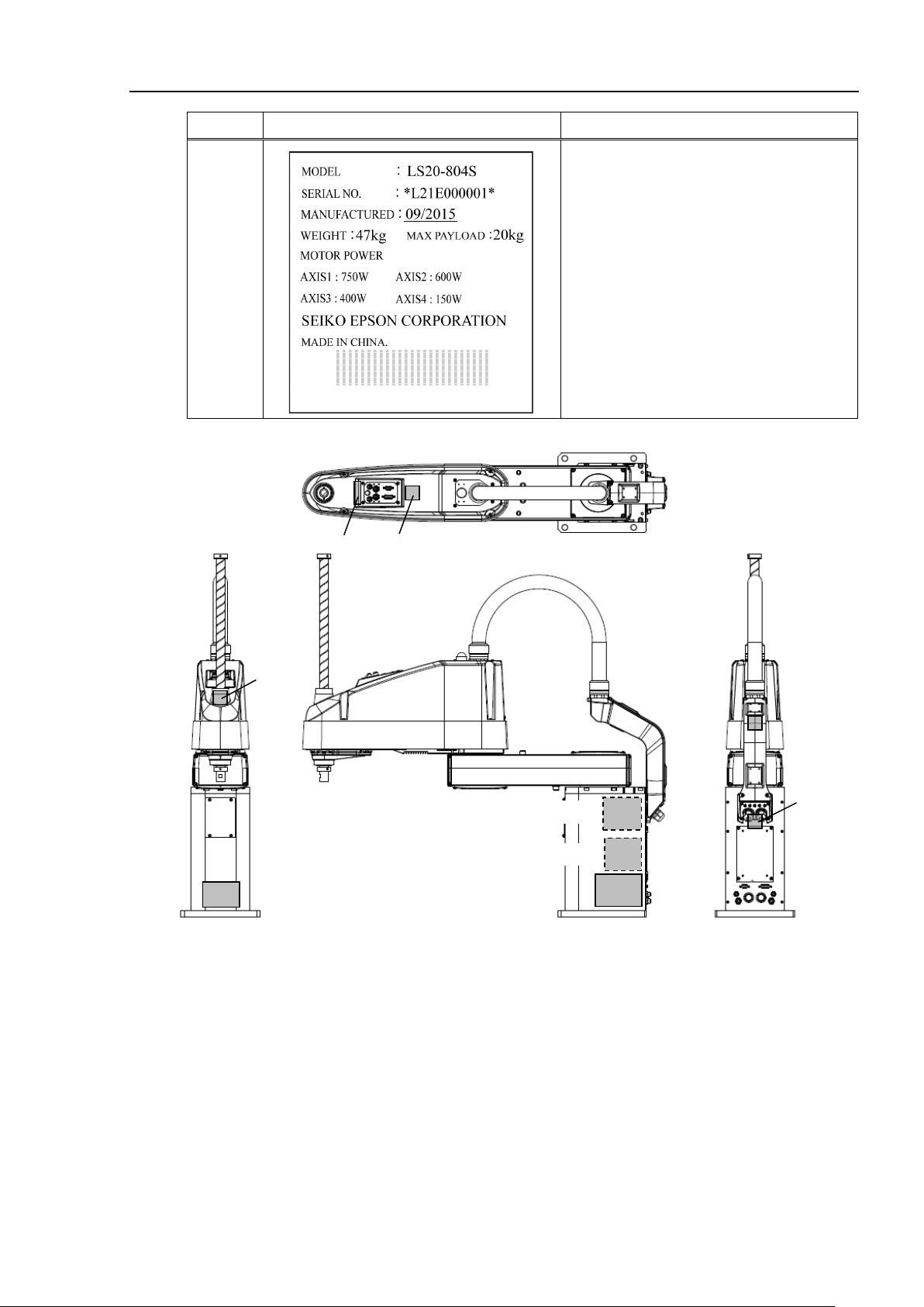
Label
Controller
Software
EPSON
RC+
Before Reading This Manual
This section describes what you should know before reading this manual.
Structure of Control System
The LS 20 series Manipulators can be used with the following combinations of Controllers
and software.
Robot Controller RC90 with the following label attached.
Turning ON/OFF Controller
RC90 EPSON RC+ 7.0 Ver.7.1.4 or later
When you see the instruction “Turn ON/OFF the Controller” in this manual, be sure to
turn ON/OFF all the hardware components. For the Controller composition, refer to the
table above.
Shape of Motors
The shape of the motors used for the Manipulator that you are using may be different from
the shape of the motors described in this manual because of the specifications.
Setting by Using Software
This manual contains setting procedures by using software. They are marked with the
following icon.
Figures in this Manual
The figures of manipulators indicated in this manual are basically Standard-model
Manipulator. Unless special instruction is provided, the specifications of Standard-model
and Cleanroom-model are the same.
Photos and Illustrations Used in This Manual
The appearance of some parts may differ from those on an actual product depending on
when it was shipped or the specifications. The procedures themselves, however, are
accurate.
LS20 Rev.1 vii
Page 10

viii LS20 Rev.1
Page 11

Setup & Operation
1. Safety 3
1.1 Conventions................................................................................................ 3
1.2 Design and Installation Safety .................................................................... 4
1.2.1 Strength of Ball Screw Spline ......................................................... 5
1.3 Operation Safety ........................................................................................ 6
1.4 Emergency Stop ......................................................................................... 8
1.5 Emergency Movement Without Drive Power ........................................... 10
1.6 ACCELS Setting for CP Motions .............................................................. 11
1.7 Manipulator Labels ................................................................................... 12
2. Specifications 14
2.1 Features of LS20 series Manipulators ..................................................... 14
2.2 Model Number .......................................................................................... 15
2.3 Part Names and Outer Dimensions ......................................................... 16
2.3.1 LS20-804* ..................................................................................... 16
2.3.2 LS20-A04* .................................................................................... 20
2.4 Specifications ........................................................................................... 24
2.5 How to Set the Model ............................................................................... 26
3. Environments and Installation 27
TABLE OF CONTE NT S
3.1 Environmental Conditions ........................................................................ 27
3.2 Base Table ................................................................................................ 28
3.3 Mounting Dimensions ............................................................................... 29
3.3.1 LS20-804* ..................................................................................... 29
3.3.2 LS20-A04* .................................................................................... 31
3.4 Unpacking and Transportation ................................................................. 33
3.4.1 Precautions for Transport ation ........................................................ 33
3.4.2 Transpor tati on ................................................................................. 34
3.5 Installation Procedure ............................................................................... 35
3.5.1 Standard-Model ............................................................................ 35
3.5.2 Cleanroom-Model ......................................................................... 36
3.6 Connecting the Cables ............................................................................. 37
3.7 User Wires and Pneumatic Tube s............................................................ 38
3.8 Relocation and Storage ............................................................................ 39
3.8.1 Precautions for Relocation and Storage ...................................... 39
3.8.2 Relocation ..................................................................................... 40
4. Setting of End Effectors 41
4.1 Attaching an End Effector ......................................................................... 41
4.2 Attaching Cameras and Valv es ................................................................ 42
4.3 Weight and Inertia Settings ...................................................................... 43
4.3.1 Weight Setting .............................................................................. 43
4.3.2 Inertia Setting ............................................................................... 45
LS20 Rev.1 ix
Page 12

TABLE OF CONTENTS
4.4 Precautions for Auto Acceleration/Deceleration of Jo int #3..................... 49
5. Motion Range 50
5.1 Motion Range Setting by Pulse Range (for All Joints) ............................. 50
5.2 Motion Range Setting by Mechanical Stops ............................................ 53
5.3 Setting the Cartesian (Rectangular) Range in the XY Coordinate
5.4 Standard Motion Range ........................................................................... 58
Maintenance
5.1.1 Max. Pulse Range of Joint #1 ...................................................... 51
5.1.2 Max. Pulse Range of Joint #2 ...................................................... 51
5.1.3 Max. Pulse Range of Joint #3 ...................................................... 52
5.1.4 Max. Pulse Range of Joint #4 ...................................................... 52
5.2.1 Setting the Mechanical Stops of Joints #1 an d #2 ....................... 54
5.2.2 Setting the Mechanical Stop of Joint #3 ....................................... 56
System of the Manipulator ( for Joi nts #1 and #2) ................................... 58
1. Safety Maintenance ................................................................... 61
2. General Maintenance ................................................................. 62
2.1 Maintenance Inspection ........................................................................... 62
2.1.1 Schedule for Maintenance Inspection .......................................... 62
2.1.2 Inspection Point ............................................................................ 63
2.2 Overhaul ................................................................................................... 64
2.3 Greasing ................................................................................................... 65
2.4 Tightening Hexagon Socket Head Cap Bolts .......................................... 66
2.5 Matching Origins ...................................................................................... 66
2.6 Layout of Maintenance Parts ................................................................... 67
3. Covers ........................................................................................ 68
3.1 Arm Top Cover ......................................................................................... 69
3.2 Arm Bottom Cover .................................................................................... 70
3.3 Arm #1 Cover ........................................................................................... 70
3.4 Connector Plate ....................................................................................... 71
3.5 Connector Sub Plate ................................................................................ 72
3.6 User Plate................................................................................................. 72
4. Cable .......................................................................................... 73
4.1 Replacing Cable Unit ............................................................................... 73
4.2 Wiring Diagrams ....................................................................................... 78
4.2.1 Signal Cable ................................................................................. 78
4.2.2 Power Cable ................................................................................. 79
4.2.3 User Cable ................................................................................... 80
4.3 Replacing M/C Cable ............................................................................... 81
x LS20 Rev.1
Page 13

TABLE OF CONTENTS
5. Arm #1 ........................................................................................ 84
5.1 Replacing Joint #1 Motor ......................................................................... 85
5.2 Replacing Joint #1 Reduction Gear Unit .................................................. 88
6. Arm #2 ........................................................................................ 91
6.1 Replacing Joint #2 Motor ......................................................................... 92
6.2 Replacing Joint #2 Reduction Gear Unit .................................................. 96
7. Arm #3 ...................................................................................... 100
7.1 Replacing Joint #3 Motor ....................................................................... 101
7.2 Replacing the Timing Be lt ...................................................................... 105
7.3 Replacing the Brake ............................................................................... 109
7.4 Checking the Timing Belt Tension .......................................................... 113
8. Arm #4 ...................................................................................... 114
8.1 Replacing Joint #4 Motor ....................................................................... 115
8.2 Replacing the Timing Be lt ...................................................................... 119
8.3 Replacing the Brake ............................................................................... 123
8.4 Replacing the Reduction Gear Unit ....................................................... 124
8.5 Checking the Timing Belt Tension .......................................................... 126
9. Bellows ..................................................................................... 127
10. Ball Screw Spline Unit ............................................................ 129
10.1 Greasing the Ball Screw Sp li ne U nit .................................................... 129
10.1.1 Standard-model (S type) .......................................................... 130
10.1.2 Cleanroom-model ..................................................................... 131
10.2 Replacing the Ball Screw Spline Unit ................................................... 133
11. Lithium Battery ........................................................................ 136
11.1 Replacing the Battery Unit (Lithium Battery ) ........................................ 138
11.2 Replacing the Resolver Board .............................................................. 139
11.3 Replacing the Control Board ................................................................ 141
12. LED Lamp .............................................................................. 142
13. Calibration .............................................................................. 143
13.1 About Calibration .................................................................................. 143
13.2 Calibration Procedure ........................................................................... 144
13.3 Accurate Calibration of Joint #2 ........................................................... 154
13.4 Calibration Procedure without using Calibration Wizard ..................... 156
14. Maintenance Parts List ........................................................... 160
LS20 Rev.1 xi
Page 14

TABLE OF CONTENTS
xii LS20 Rev.1
Page 15

Setup & Operation
This volume contains infor mation for setup and operation of the
LS20
Please read this volume
operating the Manipulators.
series Manipulators.
thoroughly before setti ng up and
Page 16

Page 17

associated instructions are not followed
death caused by electric shock exists if the associated
or physical damage to equipment and facilities exists if the
1. Safety
Installation and transportation of robots and robotic equipment shall be performed by
qualified personnel and should conform to all national and local codes. Please read this
manual and other related manuals before installing the robot system or before connecting
cables.
Keep this manual handy for easy access at all times.
1.1 Conventions
Important safety considerations are indicated throughout the manual by the following
symbols. Be sure to read the descriptions shown with each symbol.
WARNING
WARNING
Setup & Operation 1. Safety
This symbol indicates that a danger of possible serious injury or
death exists if the
properly.
This symbol indicates that a danger of possible serious injury or
instructions are not followed properly.
This symbol indicates that a danger of possible harm to people
CAUTION
associated instructions are not followed properly.
LS20 Rev.1 3
Page 18

Setup & Operation 1. Safety
Personnel who design and/or construct the robot system with this product must
read the
safety requirements before designing and/or constructing the robot system.
Designing and/or constructing the robot system without understanding the safety
requirements is extremely hazardous, may res
severe equipment damage to the robot system, and may cause serious safety
problems.
■
The Manipulator and the Controller must be used within the environmental
conditions described in their respective manuals.
designed and manufactur ed strict ly for use in a norma l indoor env iron ment. Using
the product in an environment that exceeds the specified environmental
conditions may not only shorten the life cycle of the product but may also cause
seriou
■
The robot system must be used within the installation requirements described in
the manuals. Using the robot system outside of the installation requirements
may not only shorten the life cycle of the product but also cause serious
problems.
1.2 Design and Installation Safety
Only trained personnel should design and install the robot system. Trained
personnel are defined as those who have taken robot system training and
maintenance training classes held by the manufacturer, dealer, or local
representative company, or those who understand the manuals thoroughly and
have the same knowledge and skill lev el as tho se w ho have co mplet ed the tr aini ng
courses.
To ensure safety, a safeguard must be installed for the robot system. For details
on the safeguard, refer to the Installation and Design Precautions in the Safety
chapter of the EPSON RC+ User’s Guide.
The following items are safety precautions for design personnel:
■
Safety chapter in the EPSON RC+ User’s Guide to understand the
WARNING
ult in serious bodily injury and/or
s safety problems.
Further precautions for installation are mentioned in the chapter Setup &
Operation: 3. Environments and Installation. Please read this chapter carefully to
understand safe installation procedures before installing the robots and robotic
equipment.
This product has been
safety
4 LS20 Rev.1
Page 19
Setup & Operation 1. Safety
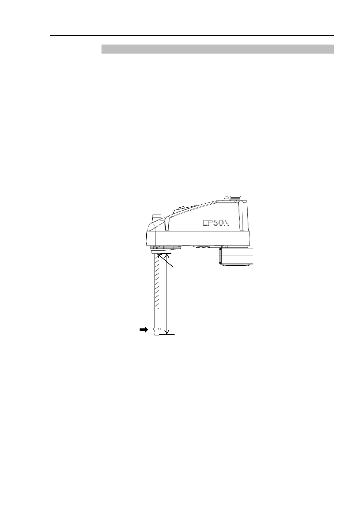
End of spline nut
F
L
1.2.1 Strength of Ball Screw Spline
If a bending load exceeding the allowable limit is placed on the ball screw spline, the
spline may be deformed or broken and not function normally.
If the load exceeding the allowance is placed, the ball screw spline needs to be replaced.
The allowable load depends on distance that the load is placed. Calculate the value by
referring to the following.
[Allowable bending moment]
M=50,000 N
Calculation example:
110 N (11.2 kgf) load is placed at 400 mm from the end of the spline nut
[Moment]
M=F
∙L=
∙
mm
110·400=44,000 N∙mm
LS20 Rev.1 5
Page 20
Setup & Operation 1. Safety
Please carefully read the
the
the robot system without understanding the safety requirements is extremely
hazardous and may result in serious bodily injury and/or sever
damage to the robot system.
■
Do not enter the operating area of the Manipulator while the power to the robot
system is turned ON. Entering the operating area with the power ON is
extremely hazardous and may cause serious safety problems as the Manipulator
may move even if it seems t o
■
Before operating the robot system, make sure that no one is inside the
safeguarded area.
even when someone is in side the safeguarded area.
The motion of the Manipulat or is always in restricted (low speeds and low power)
status to secure the safety of an operator.
while someone is inside the safeguarded area is extremely hazardous and may
result in serious safety problems in case that the Manipulator moves
unexpectedly.
■
Immediately press the Emergency Stop switch whenever the Manipulator moves
abnormally while the robot system is operated.
the Manipulator moves abnormally is extremely hazardous and may result in
serious bodily injury and/o r severe equipment damage to the robot system.
To shut off power to the robot system, pull out the power plug from the power
source.
NOT connect it direct ly to a factory power source.
■
Before performing any replacement procedure, turn OFF the Controller and
related equipment, and then pull out the power plug from the power source.
Performing any replacement procedure with the power ON is extremely
hazardous and may result in electric shock and/or malfunction of the robot
system.
■
Do not insert or pull out the motor connectors w hile the power t o the robot system
is
extremely hazardous and may result in serious bodily injury as the Manipulator
may move abnormally, and also may result in ele ctr ic sho c k and/or ma lfunc tion o f
the robot system.
1.3 Operation Safety
The following items are safety precautions for qualified Operator personnel:
■
EPSON RC+ User’s Guide before operating the robot system. Operating
Safety-related Requirements in the Safety chapter of
e equipment
be stopped.
WARNING
WARNING
■
Be sure to connect the AC power cable to a power receptacle. DO
The robot system can be operated in the mode for teaching
However, operating the robot system
Continuing the operation while
turned ON. Inserting or pulling out the motor co n nectors w ith the p ow er ON i s
6 LS20 Rev.1
Page 21
Setup & Operation 1. Safety
Whenever possible, only one person should operate the robot system.
necessary to operate t he r obot sy st em with mor e th a n one per s on, e nsure that al l
people involved com mu ni cat e with each other as to what t hey are doing and take
all necessary safety pr ecaut ions.
Joint #1, #2, and #4:
If the joints are operate d
they may get damaged early because the bearings are likely to cause oil film
shortage in such situation. To prevent early breakdown, move the joints larger
than 50 degrees
Joint #3:
If the up
the maximum stroke for fi ve to ten times a day.
Oscillation (resonance) may
(Speed:
effector load. Oscillation arises from natural oscillation frequency of the Arm
and can be controlled by follow ing measures.
■
If it is
CAUTION
■
repeatedly with t he oper ating ang le less tha n 5 degr ees ,
for about five to ten t imes a day.
-and-down motion of the hand is less than 1 0 mm, move t he joint a hal f of
■
occur continuously in low speed Manipulator motion
approx. 5 to 20%) depending on combination of Arm orientation and end
Changing Manipulator speed
Changing the teach point s
Changing the end effe c t or load
LS20 Rev.1 7
Page 22

Setup & Operation 1. Safety
1.4 Emergency Stop
If the Manipulator moves abnormally during operation, immediately press the Emergency
Stop switch. Pressing the Emergency Stop switch immediately changes the manipulator
to deceleration motion and stops it at the maximum deceleration speed.
However, avoid pressing the Emergency Stop switch unnecessarily while the Manipulator
is running normally. Pressing the Emergency Stop switch locks the brake and it may
cause wear on the friction plate of the brake, resulting in the short life of the brake.
Normal brake life cycle: About 2 years (when the brakes are used 100 times/day)
To place the system in emergency mode during normal operation, press the Emergency
Stop switch when the Manipulator is not moving.
Refer to the Controller manual for instructions on how to wire the Emergency Stop switch
circuit.
Do not turn OFF the Controller while the Manipulator is operating.
If you attempt to stop the Manipulator in emergency situations such as “Safeguard Open”,
make sure to stop the Manipulator using the E-Stop of the Controller.
If the Manipulator is stopped by turning OFF the Controller while it is operating,
following problems may occur.
Reduction of the life and damage of the reduction gear unit
Position gap at the joints
In addition, if the Controller was forced to be turned OFF by blackouts and the like while
the Manipulator is operating, make sure to check the following points after power
restoration.
Whether or not the reduction gear is damaged
Whether or not the joints are in their proper positions
If there is a position gap, perform calibration by referring to the Maintenance 16.
Calibration in this manual.
Before using the Emergency Stop switch, be aware of the followings.
- The Emergency Stop (E-STOP) switch should be used to stop the Manipulator only
in case of emergencies.
- To stop the Manipulator operating the program except in emergency, use Pause (halt)
or STOP (program stop) commands.
Pause and STOP commands do not turn OFF the motors. Therefore, the brake does
not function.
- For the Safeguard system, do not use the circuit for E-STOP.
For details of the Safeguard system, refer to the following manuals.
EPSON RC+ User’s Guide
2. Safety - Installation and Design Precautions - Safeguard System
Safety and Installation
2.6 Connection to EMERGENCY Connector
8 LS20 Rev.1
Page 23
Setup & Operation 1. Safety
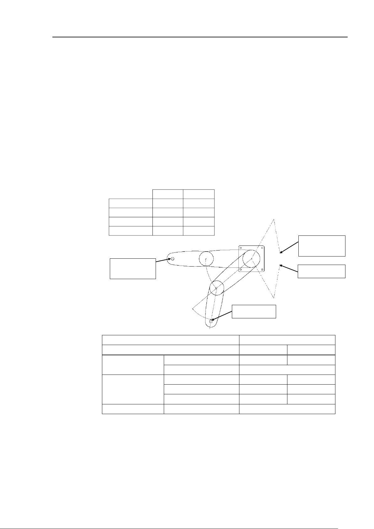
Conditions for Measurement
LS20-804*
LS20
-A04*
Accel Setting
100
100
Speed Setting
100
100
Load [kg]
20
20
Weight Setting
20
20
Joint #1
Stop position
E-Stop signal
Input position
Target position
Motion start
position
Joint #2
To check brake problems, refer to the following manuals.
Manipulator Manual Maintenance
2.1.2 Inspection While the Power is ON (Manipulator is operating)
Safety and Installation
5.1.1 Manipulator - Inspection While the Power is ON (Manipulator is operating)
Free running distance in emergency
The operating Manipulator cannot stop immediately after the Emergency Stop switch is
pressed.
The free running time/angle/distance of the Manipulator are shown below. However,
remember that the values vary depending on following conditions.
Weight of the end effector Weight of work piece Operating pose
Weight Speed Accel etc.
LS20 Rev.1 9
Controller RC90
Manipulator LS20-804* LS20-A04*
Free running time
Free running angle
Free running distance Joint #3 [mm] 110
Joint #1 + Joint #2 [sec.] 0.65 0.7
Joint #3 [sec.] 0.3
Joint #1 [deg.] 65 70
Joint #2 [deg.] 50 50
Joint #1 + Joint #2 [deg.] 115 120
Page 24
Setup & Operation 1. Safety
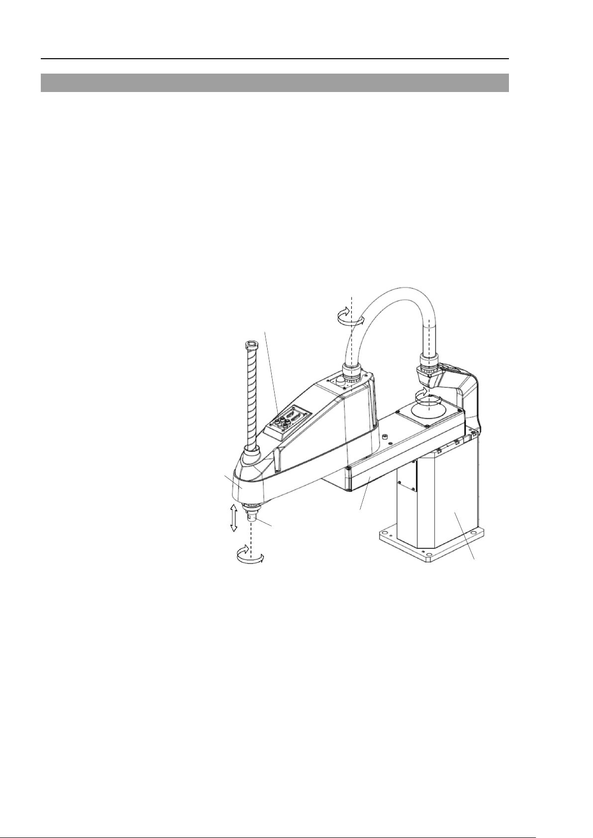
Joint #3 / Joint #4
brake release switch
Joint #1
(rotating)
Joint #2
(rotating)
Joint #3
(up and down)
Joint #4
(rotating)
Arm #1
Arm #2
+
−
+
−
+
−
+
−
Shaft
(Figure: LS20-804S)
Base
NOTE
1.5 Emergency Movement Without Drive Power
When the system is placed in emergency mode, push the arm or joint of the
Manipulator by hand as shown below:
Arm #1 Push the arm by hand.
Arm #2 Push the arm by hand.
Joint #3 The joint cannot be moved up/down by hand until the solenoid
brake applied to the joint has been released. Move the joint
up/down while pressing the brake release switch.
Joint #4 The shaft cannot be rotated by hand until the solenoid brake
applied to the shaft is released. Move the shaft while pressing
the brake release switch.
The brake release switch affects both Joints #3 and #4. When the brake release switch
is pressed in emergency mode, the brakes for both Joints #3 and #4 are released
simultaneously.
Be careful of the shaft falling and rotating while the brake release switch is pressed
because the shaft may be lowered by the weight of the end effector.
10 LS20 Rev.1
Page 25
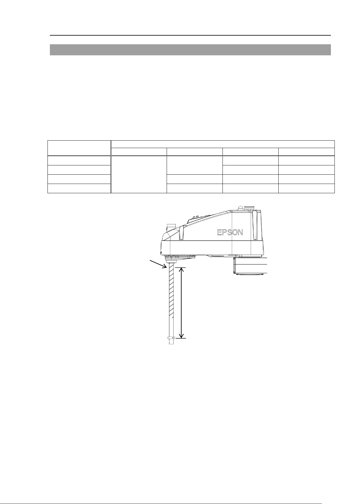
Z position
(mm)
Tip load (kg)
5 kg or less
10 kg or less
15 kg or less
20 kg or less
0 > Z >= - 100
10000 or less
9000 or less
- 100 > Z >= - 200
7000 or less
5500 or less
- 200 > Z >= - 300
7500 or less
5000 or less
3500 or less
- 300 > Z >= - 420
5500 or less
3500 or less
2500 or less
Z
-axis height
0
(Origin point)
Z
NOTE
1.6 ACCELS Setting for CP Motions
To make the Manipulator move in CP motion, see the following and set ACCELS properly
according to the motion area, load, and Z-axis height.
Improper setting may cause following problems.
Reduction of the life and damage of the ball screw spline
Set ACCELS as follows according to the Z-axis height.
ACCELS setting value by Z-axis position and tip load
10000 or less
10000 or less
Setup & Operation 1. Safety
If the Manipulator is operated in CP motion with the wrong set values, make sure to check
the following point.
Whether the ball screw spline shaft is deformed or bent
LS20 Rev.1 11
Page 26
Setup & Operation 1. Safety
to prevent hands or fingers from being
collide against the operator. This is
ly hazardous and may result in
Hazardous voltage exists while the
sling work and operate a crane and a forklift.
shaft falling and rotating
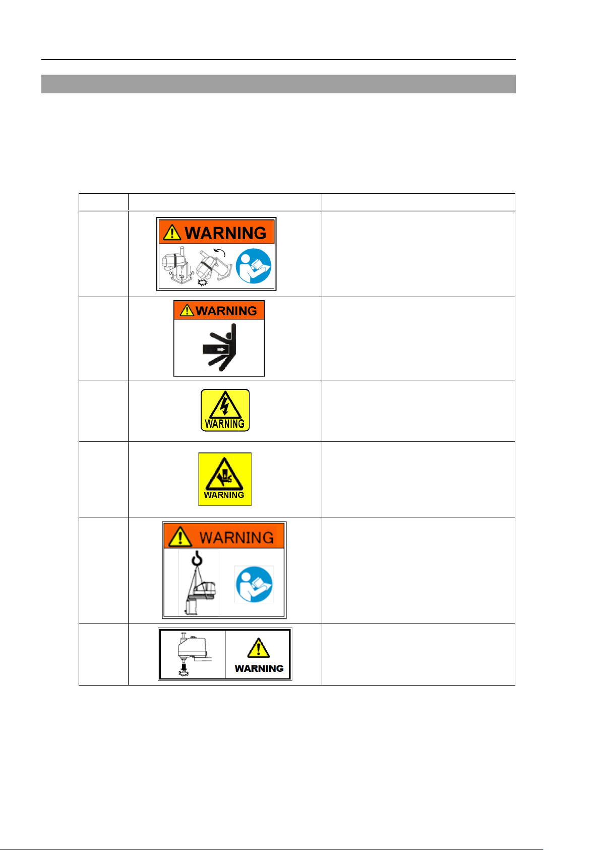
1.7 Manipulator Labels
The following labels are attached near the locations of the Manipulator where specific
dangers exist.
Be sure to comply with descriptions and warnings on the labels to operate and maintain
the Manipulator safely.
Do not tear, damage, or remove the labels. Use meticulous care when handling those
parts or units to which the following labels are attached as well as the nearby areas:
Labels NOTE
A
B
Before loosening the base mountin g screws,
hold the arm and secure it tight ly with a band
caught in the Manipulator.
Do not enter the operation area while the
Manipulator is moving. The robot arm may
extreme
serious safety problems.
C
D
E
F
Manipulator is ON. To avoid electric shock,
do not touch any internal electric parts.
You can catch your hand or fingers between
the shaft and cov er when bringing your hand
close to moving parts.
* Manipulators with bellows do not have this
label for no danger of your hand or fingers
being caught.
Only authorized personnel should perform
When these operations are performed by
unauthorized personnel, it is extremely
hazardous and may result in serious bodily
injury and/or severe equipment damage to
the robot system.
Be careful of the
while the brake release switch is pressed
because the shaft may be lowered by the
weight of the end effector.
12 LS20 Rev.1
Page 27
Setup & Operation 1. Safety
C
A
D
B
C
G
(Opposite side)
E
(Opposite side)
F
Labels NOTE
G
(Figure: LS20-804S)
LS20 Rev.1 13
Page 28

Setup & Operation 2. Specifications
2. Specifications
2.1 Features of LS20 series Manipulators
The LS20 series Manipulators are advanced manipulators pursuing high speed and high
cost-performance.
The features of the LS20 series Manipulators are as follows:
Resolver for the Position Detect or
It includes no electrical components; therefore it has high resistance to
environment and hardly breaks down.
It mounts the resolver board and battery inside the manipulator; therefore the
calibration is not required when you disconnect the M/C cable.
Large Capacity
It supports the U-axis allowable moment up to 0.45 kg·m
It stably handles large loads by optimized control based on the each load.
Tact Time Improvement by High-speed Motion
2
It improves the tact time of delicate movements by acceleration/deceleration
speed optimized for each payload and stop short technology.
14 LS20 Rev.1
Page 29
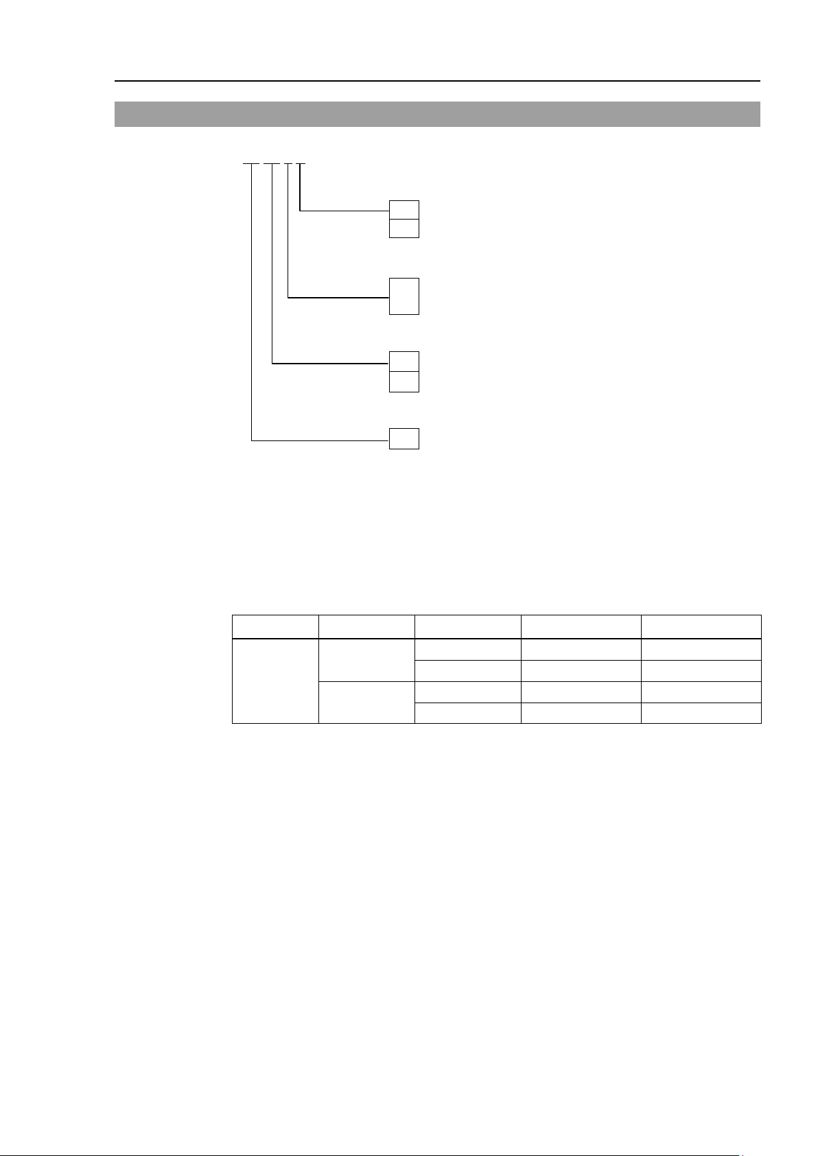
Environment
S
: Standard
C
: Cleanroom
Joint #3 stroke
: 390 mm : Cleanroom-Model (with bellows)
Arm length
80
: 800 mm
Payload
Standard
420 mm
LS20-804S
Standard
420 mm
LS20-A04S
Cleanroom
390 mm
LS20-A04C
2.2 Model Number
LS20-80 4 S
: 420 mm : Standard-Model
4
A0 : 1 0 00 mm
20 : 20 kg
Setup & Operation 2. Specifications
Environment
Cleanroom-model
This model has additional features that reduce dust emitted by the Manipulator to enable
use in clean room environments.
For details on the specifications, refer to Setup & Operation: 2.4 Specifications.
Payload Arm length Environment Joint #3 stroke Model Number
800 mm
20 kg
Cleanroom 390 mm LS20-804C
1000 mm
LS20 Rev.1 15
Page 30
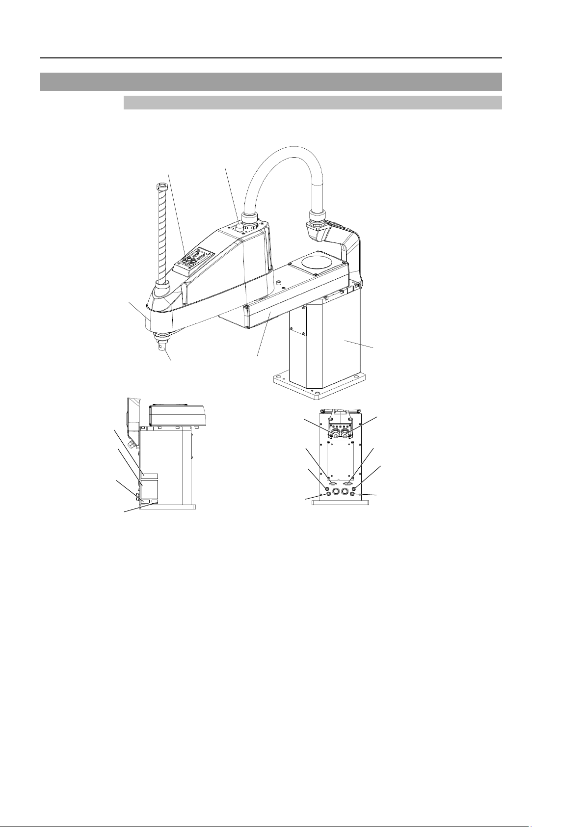
Setup & Operation 2. Specifications
Joint #3 / Joint #4
Brake release switch
Arm #1
Arm #2
Base
Shaft
MT label
(only for custom
specification)
Signature label
(Serial No.
of Manipulator)
Signal cable
Power cable
Fittings (blue)
for ø4 mm pneumatic tube
Fittings (blue) for ø6 mm
pneumatic tube
Fittings (white) for
ø6 mm
pneumatic tube
User connector
(15-pin D-sub connector)
LED lamp
CE label
User connector
(9-pin D-sub connector)
Fittings (white) for ø4 mm
pneumatic tube
KC Mark
NOTE
2.3 Part Names and Outer Dimensions
2.3.1 LS20-804*
LS20-804S (Standard-Model)
- The brake release switch affects both Joints #3 and #4. When the brake release switch is pressed
in emergency mode, the brakes for both Joints #3 and #4 are released simultaneously.
- While the LED lamp is on, the current is being applied to the manipulator. Performing any work
with the power ON is extremely hazardous and it may result in electric shock and/or improper
function of the robot system. Make sure to turn OFF the controller power before the maintenance
work.
16 LS20 Rev.1
Page 31

LS20-804S (Standard-Model)
Setup & Operation 2. Specifications
LS20 Rev.1 17
Page 32

Setup & Operation 2. Specifications
Upper bellows
Lower bellows
Exhaust port
LS20-804C (Cleanroom-Model)
The following figures show the additional parts and specifications for Cleanroom-model
when compared with the Standard-model in appearance.
18 LS20 Rev.1
Page 33

LS20-804C (Cleanroom-Model)
Setup & Operation 2. Specifications
LS20 Rev.1 19
Page 34

Setup & Operation 2. Specifications
Joint #3 / Joint #4
Brake release switch
Arm #1
Arm #2
Base
Shaft
MT label
(only for custom
specification)
Signature label
(Serial No.
of Manipulator)
Signal cable
Power cable
Fittings (blue) for ø4 mm
pneumatic tube
Fittings (blue) for ø6 mm
pneumatic tube
Fittings (white) for ø6 mm
pneumatic tube
User connector
(15-pin D-sub connector)
LED lamp
CE label
User connector
(9-pin D-sub connector)
Fittings (white) for ø4 mm
pneumatic tube
KC Mark
NOTE
2.3.2 LS20-A04*
LS20-A04S (Standard-Model)
- The brake release switch affects both Joints #3 and #4. When the brake release switch is pressed
in emergency mode, the brakes for both Joint #3 and Joint #4 are released simultaneously.
- While the LED lamp is on, the current is being applied to the manipulator. Performing any work
with the power ON is extremely hazardous and it may result in electric shock and/or improper
function of the robot system. Make sure to turn OFF the controller power before the maintenance
work.
20 LS20 Rev.1
Page 35

LS20-A04S (Standard-Model)
Setup & Operation 2. Specifications
LS20 Rev.1 21
Page 36

Setup & Operation 2. Specifications
Upper bellows
Lower bellows
Exhaust port
LS20-A04C (Cleanroom-Model)
The following figures show the additional parts and specifications for Cleanroom-model
when compared with the Standard-model in appearance.
22 LS20 Rev.1
Page 37

LS20-A04C (Cleanroom-Model)
Setup & Operation 2. Specifications
LS20 Rev.1 23
Page 38

Setup & Operation 2. Specifications
Item
LS20-804*
LS20-A04*
Arm #1, #2
800 mm
1000 mm
Arm #1
350 mm
550 mm
Arm #2
450 mm
450 mm
Joints #1, #2
9940 mm/s
11250 mm/s
Joint #3
2020 mm/s
Joint #4
1400 deg/s
Joints #1, #2
± 0.025 mm
Joint #3
± 0.01 mm
Joint #4
± 0.01 deg.
Rated
10 kg
Max.
20 kg
Joint #4 allowable
Rated
0.05 kg·m2
Max.
0.45 kg·m2
Joints #1
0.000275 deg/pulse
Joint #2
0.000439 deg/pulse
Joint #3
0.00148 mm/pulse
Joint #4
0.001046 deg/pulse
Shaft diameter
ø 25 mm
Through hole
ø 18 mm
200 × 200 mm
4 × ø16
Weight (cables not included)
47 kg : 103.6 lb
50 kg : 110.2 lb
Driving metho d
All joints
AC servo motor
Joint #1
750 W
Joint #2
600 W
Joint #3
400 W
Joint #4
150 W
Option
Installation environment
Cleanroom *3
Joint #3 down force
250 N
Installed wire for customer use
15 pin: D-sub, 9 pin: D-sub
tube for customer use
2 pneumatic tubes (ø6 mm) : 0.59 Mpa (6 kgf/cm2 : 86 psi)
2 pneumatic tubes (ø4 mm) : 0.59 Mpa (6 kgf/cm2 : 86 psi)
Ambient relative humidity
10 to 80% (no condensation)
Noise level *4
L
Aeq
= 70 dB (A)
Applicable Controller
RC90
SPEED
1 to (5) to100
ACCEL *5
1 to (10) to 120
SPEEDS
1 to (50) to 2000
ACCELS
1 to (200) to 10000
FINE
0 to (1250) to 65000
WEIGHT
0,450 to (10,450) to 20,450
CE Mark
NFPA 79 (2007 Edition)
2.4 Specifications
Arm length
Max. operating speed *1
Repeatability
Payload (Load)
moment of inertia *2
Resolution
Hand
Mounting hole
Motor
energy consumption
Installed pneumatic
Environmental
requirements
Assignable Value
( ) Default values
Ambient Temp. 5 to 40 degrees C (with minimum temperature variation)
Safety standard
24 LS20 Rev.1
EMC Directive, Machinery Directive, RoHS Directive
KC Mark / KCs Mark
ANSI/RIA R15.06-2012
Page 39

Item
LS20-804S
LS20-A04S
LS20-804C
LS20-A04C
Joint #1
± 132 deg
Joint #2
± 152 deg
Joint #3
420 mm
390 mm
Joint #4
± 360 deg
Joint #1
− 152918 to 808278
Joint #3
−283853 to 0
−263578 to 0
Joint #4
± 344064
Max.
motion range
Setup & Operation 2. Specifications
Max.
pulse range
Joint #2
± 345885
*1: In the case of PTP command.
Maximum operating speed for CP command is 2000 mm/s on horizontal plane.
*2: In the case where the center of gravity is at the center of Joint #4.
If the center of gravity is not at the center of Joint #4, set the parameter using Inertia command.
*3: The exhaust system in the Cleanroom-model Manipulator draws air from the base interior and arm cover
interior together.
A crack or other opening in the base unit can cause loss of negative air pressure in the outer part of the
arm, which can cause increased dust emission.
Do not remove the maintenance cover on the front of the base.
Seal the exhaust port and the exhaust tube with vinyl tape so that the joint is airtight.
If the exhaust flow is not sufficient, dust particle emission may exceed the specified maximum level.
Cleanliness level : Class ISO 4 (ISO14644-1)
Exhaust System : Exhaust port diameter : Inner diameter: ø12 mm / Outer diameter: ø16 mm
Exhaust tube : Polyurethane tube
Outer diameter: ø12 mm (Inner diameter:ø8 mm) or
Inner diameter ø16mm
Recommended exhaust flow rate : approx. 1000 cm
3
/s (Normal)
*4: Conditions of Manipulator during measurement as follows:
Operating conditions : Under rated load, 4-joints simultaneous motion, maximum speed, maximum
acceleration, and duty 50%.
Measurement point : In front of the Manipulator, 1000 mm apart from the motion range, 50 mm above
the base-installed surface.
*5: In general use, Accel setting 100 is the optimum setting that maintains the balance of acceleration and
vibration when positioning. Although values larger than 100 can be set to Accel, it is recommended to
minimize the use of large values to necessary motions since operating the manipulator continuously with
the large Accel setting may shorten the product life remarkably.
LS20 Rev.1 25
Page 40

Setup & Operation 2. Specifications
When you need to change the setting of the Man ipulator model, be s ure to set the
Manipulator model properly.
result in
or no operation of the Manipulator and/or cause safety
problems.
NOTE
2.5 How to Set the Model
The Manipulator model for your system has been set before shipment from the factory. It
is normally not required to change the model when you receive your system.
■
CAUTION
If an MT label is attached to the rear of a Manipulator, the Manipulator has custom
specifications. The custom specifications may require a different configuration
procedure; check the custom specifications number described on the MT label and contact
us when necessary.
The Manipulator model can be set from software.
Refer to the chapter Robot Configuration in the EPSON RC+ User’s Guide.
abnormal
Improper setting of the Manipulator model may
26 LS20 Rev.1
Page 41

Setup & Operation 3. Environments and Installation
Item
Conditions
Ambient temperature *
5 to 40 deg C (with minimum temperature variation)
First transient burst noise
2 kV or less
· Keep away from sources of electric noise.
Use an earth leakage breaker on the AC power cable of the
the electric shock and circuit breakdown caused by an unexpected water leak.
Prepare the earth leakage brake that pertains the controller you are using. For
details, refer to the contr oller manual.
CAUTION
When cleaning the M anip ulator, do not rub it strongly w ith alcoho l or
may lose luster on the coated face.
NOTE
3. Environments and Installation
3.1 Environmental Conditions
A suitable environment is necessary for the robot system to function properly and safely.
Be sure to install the robot system in an environment that meets the following conditions:
Ambient relative humidity 10 to 80% (no condensation)
Electrostatic noise 6 kV or less
Environment · Install indoors.
· Keep away from direct sunlight.
· Keep away from dust, oily smoke, salinity, metal
powder or other contaminants.
· Keep away from flammable or corrosive solvents
and gases.
· Keep away from water.
· Keep away from shocks or vibrations.
WARNING
Manipulators are not suitable for operation in harsh environments such as painting areas,
etc. When using Manipulators in inadequate environments that do not meet the above
conditions, please contact us.
* The ambient temperature conditions are for the Manipulators only. For the Controller
the Manipulators are connected to, refer to the Controller manual.
Special Env iron ment a l Conditions
The surface of the Manipulator has general oil resistance. However, if your
requirements specify that the Manipulator must withstand certain kinds of oil, please
consult your distributor.
Rapid change in temperature and humidity can cause condensation inside the
Manipulator.
If your requirements specify that the Manipulator handles food, please consult your
distributor to check whether the Manipulator gives damage to the food or not.
The Manipulator cannot be used in corrosive environments where acid or alkaline is
used. In a salty environment where the rust is likely to gather, the Manipulator is
susceptible to rust.
■
■
Controller to avoid
benzene. It
LS20 Rev.1 27
Page 42

Setup & Operation 3. Environments and Installation
LS20
Max. Reaction torque on the horizontal plate
1000
Nm
Max. Horizontal reaction force
7500
N
Max. Vertical reaction force
2000
N
Power Cable
Connector
Signal Cable
Connector
44
18
63
15
M/C Cables
(Unit : mm
)
40
80
To ensure safety, a safeguard must be inst alled
For details on the
NOTE
3.2 Base Table
A base table for anchoring the Manipulator is not supplied. P lease make or obtain the
base table for your Manipulator. The shape and size of the base table differs depending
on the use of the robot system. For your reference, we list some Manipulator table
requirements here.
The torque and reaction force produced by the movement of the Manipulator are as
follows:
The threaded holes required for mounting the Manipulator base are M12. Use mounting
bolts with specifications conforming to ISO898-1 property class: 10.9 or 12.9.
For dimensions, refer to Setup & Operation: 3.3 Mounting Dimensions.
WARNING
The plate for the Manipulator mounting face should be 20 mm thick or more and made of
steel to reduce vibration. T he surface roughness of the steel plate should be 25 μm or
less.
The table must be secured on the floor or wall to prevent it from moving.
The Manipulator must be installed horizontally.
When using a leveler to adjust the height of the base table, use a screw with M16 diameter
or more.
If you are passing cables through the holes on the base table, see the figures below.
Do not remove the M/C cables from the Manipulator.
For environmental conditions regarding space when placing the Controller on the base
table, refer to the Controller manual.
■
safeguard, refer to the EPSON RC+ User’s Guide.
for the robot system.
28 LS20 Rev.1
Page 43

Center of Joint #3
Maximum space
Motion range
Area limited by mechanical stop
Base mounting face
3.3 Mounting Dimensions
The maximum space described in figures shows that the radius of the end effector is 60
mm or less. If the radius of the end effector exceeds 60 mm, define the radius as the
distance to the outer edge of maximum space.
If a camera or solenoid valve extends outside of the arm, set the maximum range including
the space that they may reach.
Be sure to allow for the following extra spaces in addition to the space required for
mounting the Manipulator, Controller, and peripheral equipment.
Sp ace for teachin g
Sp ace for mainten ance an d inspection
(Ensure a space to open the covers and plates for maintenance.)
Sp ace for cables
The minimum bend radius of the power cable is 90 mm. When installing the cable, be
sure to maintain sufficient distance from obstacles. In addition, leave enough space for
other cables so that they are not bent forcibly.
Leave approximately 150 mm at the back of the Manipulator for battery replacement.
Ensure distance to the safeguard from the maximum motion range is more than 100 mm.
3.3.1 LS20-804*
Setup & Operation 3. Environments and Installation
Standard-Model: LS20-804S
LS20 Rev.1 29
Page 44

Setup & Operation 3. Environments and Installation
Center of Joint #3
Maximum space
Motion range
Area limited by mechanical stop
Base mounting face
390
Cleanroom-Model: LS20-804C
30 LS20 Rev.1
Page 45

Setup & Operation 3. Environments and Installation
Center of Joint #3
Maximum space
Motion range
Area limited by mechanical stop
Base mounting face
3.3.2 LS20-A04*
Standard-Model: LS20-A04S
LS20 Rev.1 31
Page 46

Setup & Operation 3. Environments and Installation
Center of Joint #3
Maximum space
Motion range
Area limited by mechanical stop
Base mounting face
Cleanroom-Model: LS20-A04C
32 LS20 Rev.1
Page 47

Setup & Operation 3. Environments and Installation
■
Only authorized personnel
forklift. When
extremely hazardous and may result in serious bodily injury and/or severe
equipment damage to the robot system.
Using a cart or similar equipment, transport the Manipulator in the same manner
as it was delivered.
After
Manipulator
■
The arm is
installation so as not to
■
To carry the Manipulator,
through the eyebolt to hang the Manipulator,
shaded area in the figure
the Manipulator without using the belt, have at least
When holding the bottom of the base by hand, be very careful not to get your
hands or fingers caught.
■
Do not hold the
may damage the
Resin duct
Metal duct
LS20-804* : approx. 47 kg :103.6 lb.
LS20-A04* : approx. 50
kg :110.2 lb.
Figure : LS20-804S
■
Stabilize the Manipulator with your hands when hoist
■
When transporting the Manipulator for a long distance, secure it to the
equipment directly so t hat t he M ani pulator never falls.
If necessary, pack the Manipulator in the same style as
3.4 Unpacking and Transportation
3.4.1 Precautions for Tr ansport ation
THE INSTALLATION SHALL BE PREFORMED BY QUALIFIED INSTALLATION
PERSONNEL AND SHOULD CONFORM TO ALL NATIONAL AND LOCAL
CODES.
should perform sling work and operate a crane and a
WARNING
■
these operations are performed by unauthorized personnel, it is
CAUTION
■
removing the bolts securing the Manipulator to the delivery equipment, the
can fall. Be careful not to get hands or fingers caught.
secured with a wire tie. Leav e the wire tie secure d until y ou finish the
get hands or fingers caught.
secure it to the delivery equipment or pass a belt
and then attach the hands on the
below (bottom of the Arm #1 and the base). If carrying
two workers to work on it.
metal duct and the resi n duct when carrying the Manipulator. It
m.
LS20 Rev.1 33
ing it.
delivery
it was delivered.
Page 48

Setup & Operation 3. Environments and Installation
Arm #1
Band fixing
position
Arm Lock
3.4.2 Transportation
Transport the Manipulator following the instructions below:
(1) Attach the eyebolts to the upper back side of the Arm.
(2) Turn the Arm #1 to face the front.
(3) Fix the Arm #1 using the arm lock so that it cannot move.
(4) Use the wire tie to fix the band for hoisting to the Arm #1. Set the band at the
shaded area in the figure below so that the band cannot move.
(5) Pass the belts through the eyebolts.
(6) Hoist the Manipulator slightly so that it does not fall. Then, remove the bolts
securing the Manipulator to the delivery equipment or pallet.
(7) Hoist the Manipulator attaching the hands on the shaded area so that it can keep
the balance. Then, move it to the base table.
34 LS20 Rev.1
Page 49

■
The
utilities, other
pinch points.
Oscillation (resonance) may
installation table.
If the oscillation occurs, improve rigidity of the table or change the speed or
acceleration
Install the Manipulator w ith
The Manipulator weigh
feet caught and/or have e quipment damage
(1)
Secure the base to the base table with four
bo
Use bolts
ISO898
Tightening
18.5 mm
Screw Hole
(depth
20
mm or more)
4-M12×40
Spring Washer
Plane Washer
(2)
Using nippers, cut off the wire tie binding
the shaft and arm retaining bracket on the
base.
2-M10
×60
Arm lock
(3)
Remove the arm lock.
NOTE
3.5 Installation Procedure
Manipulator must be installed to avoid interference with buildings, struct ures,
machines and equipment that may create a trapping hazard or
■
CAUTION
CAUTION
3.5.1 Standard-Model
■
LS20-804* : approx. 47 kg :103.6 lb.
LS20-A04* : approx. 50 kg :1 10.2 lb.
and deceleration sett ings.
Setup & Operation 3. Environments and Installation
occur during operation depending on rigidity of the
two or more people.
ts are as follows. Be careful not to get hands, fingers, or
d by a fall of the Manipulator.
lts.
with specifications conforming to
-1 Property Class: 10.9 or 12.9.
torque: 73.5 N∙m (750 kgf∙cm)
LS20 Rev.1 35
Page 50

Setup & Operation 3. Environments and Installation
(4)
Remove the bolts securing the wire ties
removed in step (2).
Wire tie
3.5.2 Cleanroom-Model
(1) Unpack it outside of the clean room.
(2) Secure the Manipulator to delivery equipment such as a pallet with bolts so that the
Manipulator does not fall.
(3) Wipe off the dust on the Manipulator with a little alcohol or distilled water on a
lint-free cloth.
(4) Carry the Manipulator in the clean room.
(5) Refer to the installation procedure of each Manipulator model and install the
Manipulator.
(6) Connect an exhaust tube to the exhaust port.
36 LS20 Rev.1
Page 51

To shut off power
source. Be sure to connect the AC power cable to a power receptacle. DO
NOT connect it direct ly to a factory power source.
■
Before
equipment,
Performing any replacement procedure with the power ON is extremely hazardous
and may result in
■
Be sure to connect
cables. (Do not
forcibl
cables, disconnection, and/or c onta ct
contact failure is extremely hazardous and may result in electric shock and/or
improper function of the robot system.
■
Grounding the manipulator is done by c onnecting w it h the cont roller. Ensure that
the
wire is improperly connect ed t o gr ound, it may result in the fire or electric sh ock.
When connecting the Manipulator to the Controller, make sure that the serial
numbers on each equipment match. Improper connection between the
Manipulator and Controller may not only cause improper function of the robot
system but also serious safety probl
Controller used. For details on the connection, refer to the
If the G series Manipulator or E2 series Manipulator is connected to the Controller
for the
Power connector
Signal connector
Connect the power cable and the signal connector of the M/C cable
to the Controller as shown below.
3.6 Connecting the Cables
■
performing any replacement procedure, turn OFF the Controller and related
and then pull out the power plug from the power source.
to the robot system, pull out the power plug from the power
electric shock and/or malfunction of the robot system.
Setup & Operation 3. Environments and Installation
WARNING
CAUTION
put heavy objects on the cables. Do not bend or pull the cables
y.) The unnecessary strain on the cables may result in damage to the
failure. Damaged cables, disconnection, or
controller is grounded and the cables are correctly connected. If the ground
■
the cables properly. Do not allow unnecessary strain on the
ems. The connection method varies with the
Controller manual.
PS series (ProSix), it may result in malfunction of the Manipulator .
For the Manipulator of Cleanroom-model, use it with an exhaust system.
For details, refer to Setup & Operation: 2.4 Specifications.
Cable Connections
LS20 Rev.1 37
Page 52

Setup & Operation 3. Environments and Installation
Only authorized or certified personnel should be allowed to perform wiring.
Wiring by unauthorized
malfunction of the robot system.
Rated Voltage
Allowable Current
Wires
Nominal Sectional Area
Note
15
9
Do not apply the current mor e t han 1A to the manipulator.
Maker
Standard
Suitable Connector
DA-15PF-N
(Solder type)
Clamp Hood
DA-C8-J10-F2-1R
(Connector setscrew: #4-40 NC)
DE-9PF-N
Clamp Hood
DE-C8-J9-F2-1R
(Connector setscrew: #4-40 NC)
Max. Usable Pneumatic Pressure
Pneumatic T ubes
Outer Diameter × Inner Diameter
2
2
Fitting (white)
for ø4 mm pneumatic tube
Fitting (blue)
for ø6 mm pneumatic tube
User connector
(15-pin D-sub connector)
User connector
(15-pin D-sub connector)
Fitting (white)
for ø6 mm pneumatic tube
Detail view from A
Detail view from B
B
LS20-804*
Brake release switch
Fitting (blue)
for ø6 mm pneumatic tube
Fitting (blue)
for ø4 mm pneumatic tube
Exhaust port
(Cleanroom-model only)
Fitting (blue)
for ø4 mm pneumatic tube
User connector
(9-pin D-sub connector)
User connector
(9-pin D-sub connector)
Fitting (white)
for ø4 mm pneumatic tube
Fitting (white)
for ø6 mm pneumatic tube
3.7 User Wires and Pneumatic Tubes
■
or uncertified personnel may result in bodily injury and/or
CAUTION
User electrical wires and pneumatic tubes are contained in the cable unit.
Electrical Wires
WARNING
AC/DC30 V 1 A
0.211 mm2
Twist pair
Unshielded
■
15 pin
Suitable Connector
JAE
(Solder type)
9 pin
Pins with the same number, indicated on the connectors on both ends of the cables, are
connected.
Pneumatic Tubes
0.59 MPa (6 kgf/cm2 : 86 psi)
Fittings for ø6 mm and ø4 mm (outer diameter) pneumatic tubes are supplied on both ends
of the pneumatic tubes.
ø 6 mm × ø 4 mm
ø 4 mm × ø 2.5 mm
38 LS20 Rev.1
Page 53

■
Only authorized personnel
forklift. When
extremely hazardous and may result in serious bodily injury and/or severe
equipment damage to the robot system.
Before relocating the Mani pul at or,
to prevent hands or finger s from
■
When removing the anchor bolts, support the Manipulator to prevent falling.
Removing the anchor bol
and then get hands, fingers, or feet caught.
■
To
Manipulator to the deliv ery
the main cable fitting, and the bottom of the
bottom of the base by hand, be very careful not to get hands or fingers c aught.
■
Stabilize the Manipulator with your hands when hoist
extremely hazardous and may r esult in fall of the Manipulator.
3.8 Relocation and Storage
3.8.1 Precautions for R eloc ati on and Storage
Observe the following when relocating, storing, and transporting the Manipulators.
The installation shall be performed by qualified installation personnel and should
conform to all national and loca l codes.
WARNING
■
these operations are performed by unauthorized personnel, it is
Setup & Operation 3. Environments and Installation
should perform sling work and operate a crane and a
fold the arm and secure it tight ly with a wire tie
being caught in the M anipulator .
ts without support may result in a fall of the Manipu lator,
CAUTION
carry the Manipulator, have two or more people to work on it and secure the
equipment or hold the bot tom o f Arm #1, the bottom of
base by hand. W hen holding the
ing it. Unstable hoisting is
When transporting the Manipulator for a long distance, secure it to the delivery
equipment so that the Ma nip ulat or cannot fall.
If necessary, pack the Manipulator in the same way as it was delivered.
When the Manipulator is used for a robot system again after long-term storage,
perform a test run to verify t hat it w or ks prop er ly, and then operate it thorough ly.
Transport and st ore the Manipulator in the range o f -25°C to +55°C.
Humidity within 10% to 90% is recommended.
When condensation occurs on the Manipulator during transport or storage, turn
ON the power only after the condensation dries.
Do not shock or shake the Manip ul at or dur ing transport.
LS20 Rev.1 39
Page 54

Setup & Operation 3. Environments and Installation
Install
The Manipulator
weigh
fingers, or feet caught
and/or have equipment da ma ge
Wire tie
Example of Arm Retaining Posture
NOTE
3.8.2 Relocation
■
CAUTION
(1) Turn OFF the power on all devices and unplug the cables.
(2) Cover the arm with a sheet so that the arm will not be damaged.
or relocate the Manipulator with two or more people.
ts are as follows. Be careful not to get hands,
d by a fall of the Manipulator.
LS20-804* : approx. 47 kg :103.6 lb.
LS20-A04* : approx. 50 kg :110.2 lb.
Remove the mechanical stops if using them to limit the motion range of Joints #1 and
#2. For details on the motion range, refer to Setup & Operation: 5.2 Motion Range
Setting by Mechanical Stops.
Insert the bolt to the screw hole on the arm and tie the bolt with the metal duct using a
string. If fixing the arm using the shaft, fix it with adequate strength not to deform
the spline.
For details on strength of the ball screw spline, refer to Setup & Operation: 1.2.1
Strength of Ball Screw Spline.
(3) Hold the bottom of Arm #1 by hand to unscrew the anchor bolts.
Then, remove the Manipulator from the base table.
40 LS20 Rev.1
Page 55

If you use an end effector equipped with a gripper or chuck, connect wires and/or
pneumatic
when the
wires and
as the work piece is released w hen the Emergency Stop switch is pressed.
I/O
by power disconnect ion, the
robot system
- Attach
For the shaft dimensions,
Setup
& Operation:
- Do not move the upper limit mechanical stop on the lower side of the shaft.
Otherwise, when
is performed, the upper limit mechanical stop may hit
the Manipulator, and the r
- Use a split muff coupling with an M4 bolt or larger to attach the end effector to the
shaft.
- Joint #3
by hand because the solenoid brake is applied to the
joint while power
This prevents t
hitting peripheral
equipment in the case that the shaft is lowered
the
effector when the
is disconnected during
operation, or when the motor is turned OFF even
though the
To move Joint #3 up/down or rotate Joint #4 while
attaching an end effector
move the joint up/down or rotate the joint while
pressing
Brake release switch
The shaft may be lowered by
the weight of the end effector.
This button
switch
The respective brakes for Joints #3 and #4 are released simultaneously.
- Be careful of the
pressed
because
4. Setting of End Effectors
4.1 Attaching an End Effector
Users are responsible for making their own end effector(s). Before attaching an end
effector, observe these guidelines.
■
tubes properly so that the gripper does not release the work piece
power to the robot system is turned OFF. Improper connection of the
CAUTION
outputs are configured at the factory s o that t hey are auto mat ically shut off (0)
Shaft
/or pneumatic tubes may damage the robot system and/or work piece
.
an end effector to the lower end of the shaft.
2. Specifications.
Setup & Operation 4. Setting of End Effectors
Emergency Stop switch, or the safety features of the
and the overall dimensions of the Manipulator, refer to
“Jump motion”
obot system may not function properly.
Brake release switch
and #4 cannot be moved up/down and rotate
to the robot system is turned OFF.
he shaft from
end effector is rotated by the weight of the end
power
power is turned ON.
, turn ON the Controller and
LS20 Rev.1 41
the brake release switch.
switch is a momentary-type; the brake is released only while the button
is being pressed.
shaft falling and rotating while the brake release switch is
the shaft may be lowered by the weight of the end effector.
and
Page 56

Setup & Operation 4. Setting of End Effectors
- When
interfere
with
the outer diameter of the end effector, the size of the
work piece
system layout, pay
attention to the interference area of the end effector.
(Figure: LS20-804S)
From the base mounting face
4 × M4
depth 10
4 × M4
depth 10
2 × M4
depth 10
Layouts
you operate the manipulator with an end effector, the end effector may
the Manipulator because of
, or the position of the arms. When designing your
4.2 Attaching Cameras and Valves
The bottom of the Arm #2 has threaded holes as shown in the figure below. U se these
holes for attaching cameras, valves, and other equipment. [Unit: mm]
42 LS20 Rev.1
Page 57

The total weight of the end effector and the work piece must
.
The
kg
Always set the Weight parameters according to the load. Setting a value that is
smaller than the actual load may cause errors, excessive shock, insufficient
function of the Manipulator,
Enter a value into the [Load inertia:] text box on the [Inertia] panel (
[Robot
M
When you attach the equipment near
When you attach the equipment to the end of Arm #2:
W
WM = M (LM)2/(L2)2
W
M
L
L
L
:
:
:
:
:
EPSON
RC+
4.3 Weight and Inertia Settings
To ensure optimum Manipulator performance, it is important to make sure that the load
(weight of the end effector and work piece) an d moment of inertia of the load are within
the maximum rating for the Manipulator, and that Joint #4 does not become eccentric.
If the load or moment o f inertia exceeds the rating or if the load becomes eccentric, follow
the steps below, “4.3.1Weight Setting” and “4.3.2 Inertia Setting” to set parameters.
Setting parameters makes the PTP motion of the Manipulator optimal, reduces vibration to
shorten the operating time, and improves the capacity for larger loads. In addition, it
reduces persistent vibration produced when the moment of inertia of the end effector and
work piece is larger than the default setting.
CAUTION
4.3.1 Weight Setting
■
LS20 series Manipulators are not designed to work with loads exceeding 20
.
Setup & Operation 4. Setting of End Effectors
not exceed 20 kg
and/or shorten the life cyc le of parts/mechanisms.
The acceptable weight capacity (end effector and work piece) in LS20 series is 10 kg at
the default rating / 20 kg at the max i mum. When the load (weight of the end effector and
work piece) exceeds the rating, change the setting of Weight parameter.
After the setting is changed, the maximum acceleration/deceleration speed of the robot
system at PTP motion corresponding to the “Weight Parameter” is set automatically.
Load on the Shaft
The load (weight of the end effector and work piece) on the shaft can be set by Weight
parameter.
[Tools] -
anager]). (You may also execute the Inertia command from the [Comm and Window].)
Load on the Arm
When you attach a camera or other devices to the arm, calculate the weight as the
equivalent of the shaft. Then, add this to the load and enter the total weight to the Weight
parameter.
Equivalent Weight Formula
Arm #2:
equivalent weight
M
weight of camera etc.
length of Arm #1
1
length of Arm #2
2
distance from rotation center of Joint #2 to center of gravity
M
LS20 Rev.1 43
of camera etc.
= M (L1)2/(L1+L2)2
M
Page 58

Setup & Operation 4. Setting of End Effectors
<Example>
A “1
mm
away from the rotation center of Joint #2) with a load weight of “1 kg”.
M=1
L
L
W
(round up)
W+W
Enter
Shaft
Weight of
camera
M=1kg
W=1kg
L2=450
mm
LM=550 mm
Joint #2
140
120
100
80
60
40
20
0
5 10
15
20 (kg)
Weight setting
(%)
LS20-A0
LS20-80
80
65
120
120
100
75
55
*
The percentage in the graph is
based on the speed at rated
weight (10 kg) as 100%.
160
140
120
100
80
60
40
20
(%)
LS20-A0
LS20-80
0
5
10
15
20 (kg)
Weight setting
140
110
100
87
120
130
150
83
75
* The percentage in the graph is
based on the acceleration
/ deceleration at rated weight
kg” camera is attached to the end of the LS20 series arm (550
=450
2
=550
M
=1 × 5502 / 4502 = 1.494 1.5
M
=1+1.5=2.5
M
“2.5” for the Weight Parameter.
Automatic speed setting b y Weight
Automatic acceleration/ deceleration setting by Weight
44 LS20 Rev.1
Page 59

The
must be
work with
inertia parameter to t he correct mome nt of inertia. Setting a value that is smaller
than the actual moment of inertia may cause errors, excessi
function of the Manipulator, and/ or shor t en t he life cycle of parts/mechanisms
Enter a value into the [Load inertia:] text box on the [Inertia] panel (
[Robot
M
0 0.10 0.20 0.30 0.40 (kg・m2)
Moment of inertia setting
120
100
80
60
40
20
(%)
115
12.8
7.4
100
EPSON
RC+
CAUTION
Setup & Operation 4. Setting of End Effectors
4.3.2 Inertia Setting
Moment of Inertia and the Inertia Setting
The moment of inertia is defined as “the ratio of the torque applied to a rigid body and its
resistance to motion”. This value is typically referred to as “the moment of inertia”,
“inertia”, or “GD
end effector) attached to the shaft, the moment of inertia of load must be considered.
■
moment of inertia of the load (weight of the end effector and work piece)
0.45 kg·m2 or less. The LS20 series Manipulators are not designed to
2
”. When the Manipulator operates with additional objects (such as an
a moment of inertia exceeding 0.45 kg·m2. Always set the moment of
ve shock, insufficient
.
The acceptable moment of inertia of load for a LS20 series Manipulator is 0.05 kgm2 at
the default rating and 0.45 kgm
2
at the maximum. When the moment of inertia of the
load exceeds the rating, change the setting of the moment of inertia parameter of the
Inertia command. After the setting is changed, the maximum acceleration/deceleration
speed of Joint #4 at PTP motion corresponding to the “moment of inertia” value is set
automatically.
Moment of inertia of load on t he s haft
The moment of inertia of load (weight of the end effector and work piece) on the shaft can
be set by the “moment of inertia” parameter of the Inertia command.
[Tools] -
anager]). (You may also execute the Inertia command from the [Comm and Window].)
Automatic acceleration/ deceleration setting of Joint #4 by Inertia (moment of inertia)
LS20 Rev.1 45
Page 60

Setup & Operation 4. Setting of End Effectors
The
20
eccentric quantity
Always set the eccentric quantity
parameter according to the eccentric quantity. Setting a value that is smaller
than the actual
function of the Manipulator, and/ or shor t en t he life cycle of parts/mechanisms
Position of load’s center of gravity
Rotation center
Eccentric quantity (200 mm or les s)
Eccentric Quantity
Enter a value into the [Eccentricity:] text box on the [Inertia] panel (
[Robot
M
* The percentage in the graph is
based on the acceleration /
deceleration at rated eccentricity
(0 mm) as 100%.
120
100
80
60
40
20
0 50 100 150 200 (mm)
Eccentricity setting
70
50
25
(%)
100
EPSON
RC+
Eccentric Quantity and t he I ner t ia Sett ing
■
eccentric quantity of load (weight of the end ef fect or and wor k piece) must be
0 mm or less. The LS20 series Manipulators are not designed to work with
exceeding 200 mm.
CAUTION
eccentric quantity may cause er r or s, excessive shock, insufficient
The acceptable eccentric quantity of load in LS20 series is 0 mm at the default ratin g and
200 mm at the maximum. When the eccentric quantity of load exceeds the rating, change
the setting of eccentric quantity parameter of Inertia command. After the setting is
changed, the maximum acceleration/deceleration speed of the Manipulator at PTP motion
corresponding to the “eccentric quantity” is set automatically.
.
Eccentric quantity of load on t he shaft
The eccentric quantity of load (weight of the end effector and work piece) on the shaft can
be set by “eccentric quantity” parameter of Inertia command.
[Tools] -
anager]). (You may also execute the Inertia command from the [Comm and Window].)
Automatic acceleration/ deceleration setting by Inerti a ( ecc ent r i c quantity)
46 LS20 Rev.1
Page 61

Setup & Operation 4. Setting of End Effectors
Work piece (b)
Work piece (c)
End effector (a)
Joint #3 shaft
Rotation center
Moment of inertia
of end effector (a)
=
Moment of inertia
of work piece (b)
+
Moment of inertia
of work piece (c)
+
Whole moment
of inertia
Calculating the Moment of Inertia
Refer to the following examples of formulas to calculate the moment of inertia of load
(end effector with work piece).
The moment of inertia of the entire load is calculated by the sum of each part (a), (b), and
(c).
The methods for calculating the moment of inertia for (a), (b), and (c) are shown below.
Calculate the total moment of inertia using the basic formulas.
LS20 Rev.1 47
Page 62

Setup & Operation 4. Setting of End Effectors
h
b
L
Mass (
m)
Rectangular parallelepiped
’s center of gravity
Rotation center
m
+ m × L2
b2 + h2
12
m
+ m × L2
r 2
2
Mass (m)
L
r
Cylinder’s center of gravity
Rotation center
m
r 2+ m × L2
2
5
Sphere’s center of gravity
r
Mass (m)
L
Rotation center
(a) Moment of inertia of a rectangular parallelepiped
(b) Moment of inertia of a cy linder
(c) Moment of inertia of a sphere
48 LS20 Rev.1
Page 63

Setup & Operation 4. Setting of End Effectors
* The percentage in the graph is
based on the acceleration /
deceleration at the upper-limited
120
100
80
60
40
20
0 - 100 - 200 - 300 - 400 (mm)
Height of the shaft
(%)
(-150, 100)
(-313, 24)
(0, 100)
LS20-804*
(-
420, 24)
* The percentage in the graph is
based on the acceleration /
deceleration at the upper-limited
120
100
80
60
40
20
0 - 100 - 200 - 300 - 400 (mm)
Height of the shaft
(%)
(-100, 100)
(-317, 24)
(0, 100)
(-420,
24)
LS20-A04*
NOTE
4.4 Precautions for Auto Acceleration/Deceleration of Joint #3
When you move the Manipulator in horizontal PTP motion with Joint #3 (Z) at a high
position, the motion time will be faster.
When Joint #3 gets below a certain point, then auto acceleration/deceleration is used to
reduce acceleration/deceleration. The higher the position of the shaft is, the faster the
motion acceleration/deceleration is. However, it takes more time to move Joint #3 up
and down. Adjust the position of Joint #3 for the Manipulator motion after considering
the relation between the current position and the destination position.
The upper limit of Joint #3 during horizontal motion using Jump command can be set by
the LimZ command.
When moving the Manipulator horizontally while the shaft is being lowered, it may cause
over-shoot at the time of final positioning.
Automatic acceleration/ deceleration vs. Joint #3 position
LS20 Rev.1 49
Page 64

Setup & Operation 5. Motion Range
When setting up the motion range for safety, both the pulse range and
mechanical stops mu st always be set at the same time.
Mechanical
stop
Rectangular range setting
Pulse range
Motion range
Mechanical
stop
The pulse range can be set on the [Range] panel shown by selecting [Tools]
Manager]. (You may also execute the Range command from the [Command Window].)
EPSON
RC+
NOTE
5. Motion Range
■
CAUTION
The motion range is preset at the factory as explained in Setup & Operation: 5.4 Standard
Motion Range. That is the maximum motion range of the Manipulator.
There are three methods for setting the motion range described as follows:
1. Setting by pulse range (for all joints)
2. Setting by mechanical stops (for Joints #1 to #3)
3. Setting the Cartesian (rectangular) range in the X, Y coordinate system of the
Manipulator (for Joints #1 and #2)
When the motion range is changed due to layout efficiency or safety, follow the
descriptions in 5.1 to 5.3 to set the range.
5.1 Motion Range Setting by Pulse Range (for All Joints)
Pulses are the basic unit of Manipulator motion. The motion range of the Manipulator is
controlled by the pulse range between the pulse lower limit and upper limit of each joint.
Pulse values are read from the encoder output of the servo motor.
For the maximum pulse range, refer to the following sections.
The pulse range must be set inside of the mechanical stop range.
5.1.1 Max. Pulse Range of Joint #1
5.1.2 Max. Pulse Range of Joint #2
5.1.3 Max. Pulse Range of Joint #3
5.1.4 Max. Pulse Range of Joint #4.
Once the Manipulator receives an operating command, it checks whether the target
position specified by the command is within the pulse range before operating. If the
target position is out of the set pulse range, an error occurs and the Manipulator does not
move.
-[Robot
50 LS20 Rev.1
Page 65

Setup & Operation 5. Motion Range
+Y
+X 0 pulse
+ B
- B
+ A
- A
A: Max. Motion Range
B: Max. Pulse Range
- B
+ B
0 pulse
- A
+ A
A: Max. Motion Range
B: Max. Pulse Range
5.1.1 Max. Pulse Range of Joint #1
The 0 (zero) pulse position of Joint #1 is the position where Arm #1 faces toward the
positive (+) direction on the X-coordinate axis.
When the 0 pulse is a starting point, the counterclockwise pulse value is defined as the
positive (+) and the clockwise pulse value is defined as the negative (-).
LS20-804*
LS20-A04*
±132 deg. - 152918 ~ 808278 pulse
5.1.2 Max. Pulse Range of Joint #2
The 0 (zero) pulse position of Joint #2 is the position where Arm #2 is in-line with Arm #1.
With the 0 pulse as a starting point, the counterclockwise pulse value is defined as the
positive (+) and the clockwise pulse value is defined as the negative (-).
LS20-804*
± 152 deg.
± 345885 pulse
LS20-A04*
LS20 Rev.1 51
Page 66

Setup & Operation 5. Motion Range
Upper limit: 0 pulse
: +X 0 ± 344064 pulse
+Y
Clockwise (-value)
Counterclockwise (+value)
NOTE
5.1.3 Max. Pulse Range of Joint #3
The 0 (zero) pulse position of Joint #3 is the position where the shaft is at its upper limit.
The pulse value is always negative because Joint #3 always moves lower than the 0 pulse
position.
Joint #3 Stroke Lower Limit Pulse
LS20-804S
Standard-model 420 mm
-283853 pulse
LS20-A04S
LS20-804C
Cleanroom-model 390 mm
-263578 pulse
LS20-A04C
For t he Cleanroom-model (LS20-804C/LS20-A04C), the motion range set with the Joint
#3 mechanical stop cannot be changed.
5.1.4 Max. Pulse Range of Joint #4
The 0 (zero) pulse position of Joint #4 is the position where the flat near the end of the
shaft faces toward the end of Arm #2. With the 0 pulse as a starting point, the
counterclockwise pulse value is defin ed as the positive (+) and the clockwise pulse value
is defined as the negative (-).
52 LS20 Rev.1
Page 67

Setup & Operation 5. Motion Range
Mechanical stop of Joint #2
(Fixed)
Mechanical stop of
Joint #1 (Adjustable)
Mechanical stop of Joint #3
(Lower limit mechanical stop)
(Do not move the upper
limit mechanical stop.)
Mechanical stop of
Joint #1 (Fixed)
Mechanical stop of
Joint #2 (Adjustable)
5.2 Motion Range Setting by Mechanical Stops
Mechanical stops physically limit the absolute area that the Manipulator can move.
Both Joints #1 and #2 have threaded holes in the positions corresponding to the angle for
the mechanical stop settings. Install the bolts in the holes corresponding to the angle that
you want to set.
Joints #3 can be set to any length less than the maximum stroke.
LS20 Rev.1 53
Page 68

Setup & Operation 5. Motion Range
a
b
Views from the bottom of A r m #1
Joint #1 Mechanical Stops
a
b
LS20-A04*
Setting Angle
122 deg
122 deg
Pulse Value
444188 pulse
444188 pulse
b
a
Views from the top of A r m #1
Joint #2 Mechanical Stops
a
b
LS20-A04*
Setting Angle
135 deg
135 deg
Pulse Value
307200 pulse
307200 pulse
(1) Turn OFF the
(2) Install a hexagon socket head cap bolt into the hole corresponding to the setting angle,
and
Hexagon socket head cap
bolt (fully threaded)
The number
of bolts
Recommended
tightening torque
(3) Turn ON the
5.2.1 Setting the Mechanical Stops of Joints #1 and #2
Both Joints #1 and #2 have threaded holes in the positions corresponding to the angle for
the mechanical stop settings. Install the bolts in the holes corresponding to the angle that
you want to set.
Install the bolts for the mechanical stop to the following position.
LS20-804*
-
-
LS20-804*
-
-
Controller.
tighten it.
Joint
1
2
M10 × 65
M10 × 50
1 bolt /
one side
Controller.
54 LS20 Rev.1
13.0 N⋅m (132.7 kgf⋅cm)
Page 69

Setup & Operation 5. Motion Range
(4) Set the pulse range corresponding to the new
Be sure to set the pulse range
Example:
-
Execute the following command
(5) Move the arm by hand until it touches the mechanical stops, and make sure that the
arm does not hit
(6) O
and
Make sure that the arm does not hit the mechanical
stops.
Example
-
Execute the following command
The Pulse command (Go Pulse command) moves
at
the same time. Specify safe positions after considering motion of not only the joints
whose pulse range have been changed, but also other joints
In this example, Joint #1 is moved to the
(pulse value:
327680
If the arm
s or if an error occurs after the arm hits the
mechanical stops
reset the pulse range to a narrower setting or extend the
position
RC+
EPSON
RC+
NOTE
positions of the mechanical stops.
inside the positions of the mechanical stop range.
Using LS20-804S
The angle of Joint #1 is set from –110 degrees to +110 degrees.
The angle of Joint #2 is set from
125 degrees to +125 degrees.
s from the [Command W indow] .
>JRANGE 1,
>JRANGE 2,-
-400498, 400498 ' Sets the pulse range of Joint #1
284445, 284445 ' Sets the pulse range of Joint #2
>RANGE ' Checks the setting using Range
-400498, 400498, -284445, 284445, -283853
, 0, -344064, 344064
any peripheral equipment during operation.
perate the joint changed at low speeds until it reaches the positions of the minimum
maximum pulse range.
(Check the position of the mechanical stop and the motion range you set.)
: Using LS20-804S
The angle of Joint #1 is set from -110 degrees to +110 degrees.
EPSON
The angle of Joint #2 is set from
s from the [Command W indow] .
125 degrees to +125 degrees.
>MOTOR ON ' Turns ON the motor
>CP ON ' Enters low-power mode
>SPEED 5 ' Sets at low speeds
>PULSE -400498,0,0,0 ' Moves to the min. pulse positio n of Joint #1
>PULSE 400498,0,0,0 ' Moves to the max. pulse positio n of Joint #1
>PULSE 327680,-284445,0,0 ' Moves to the min. pulse positi on of Joint #2
>PULSE 327680,284445,0,0 ' Moves to the max. pulse position of Joi nt #2
all joints to the specified positions
.
center of its motion range
) when checking Joint #2.
is hitting the mechanical stop
, either
s of the mechanical stops within the limit.
LS20 Rev.1 55
Page 70

Setup & Operation 5. Motion Range
(1)
Turn ON the Controller and turn OFF the motors using the Motor OFF command.
(2)
Push up the shaft while pressing the
brake release switch.
Do not push the shaft up to its upper
limit or it will be difficult for the arm
top cover to be removed. Push the
shaft up to a position where the Joint #3
mechanical stop can be changed.
Lower limit
mechanical
stop screw
2-M5×6 set screw
+ 2-M5 bush
Brake release switch
Shaft
When you press
the end effector.
(3)
Turn OFF the
(4)
Loosen the lower limit mechanical stop screw (
A mechanical stop is mounted on both the top and
the position of the lower limit mechanical stop on the top can be changed. Do not
remove the upper limit mechanical stop on the bottom because the calibration point of
Joint #3 is specified
(5)
The upper end of the shaft
maximum stroke. Move the lower
limit mechanical stop down by the
length you want to limit the stroke.
For example, when the lower limit
mechanical stop is set at “
stroke, the lower limit Z coordinate
value is
to “
”, move the lower limit
mechanical stop down
calipers to measure the distance when
adjusting
Measure
this distance.
(6)
Firmly tighten the lower limit mechanical stop
Recommended tightening torque:
(7)
Turn ON the
NOTE
NOTE
NOTE
5.2.2 Setting the Mechanical Stop of Joint #3
This method applies only to the Standard-model manipulator (LS20-**4S).
For t he Cleanroom-model (
stop cannot be changed.
Be sure to hold the shaft by hand while pressing the button.
LS20-**4C), the motion range set with the Joint #3 mechanical
the brake release switch, the shaft may lower due to the weight of
Controller.
2-M5×6 set screw).
bottom of Joint #3. However, only
using the stop.
defines the
420 mm”
“-420”. To change the value
-100
“320 mm”. Use
56 LS20 Rev.1
the mechanical stop.
screw (2-M5×6 set screw).
3.9 N⋅m (39.8 kgf⋅cm)
Controller.
Page 71

Setup & Operation 5. Motion Range
(8)
Move
then
check the lower
.
Otherwise, the joint
(9)
Calculate the lower limit pulse
shown below
and set the value.
T
he lower limit Z coordinate
value
** For the Joint #3 resolution,
Enter the
>JRANGE 3,X,0 ' Sets the pulse range of Joint #3
(10)
Using th e
Joint # 3 to the lower li mit
position of the pu lse range at low speed.
than
the pulse range, Joint #3
When
the error occurs, either change
or extend the position
of the mechanical stop within the limit.
If it is difficult to check whether Joint #3 hits a mechanical stop, turn OFF the
Controller and lift the arm top cover to check the condition causing the problem from
the side.
Enter the value
>MOTOR ON
>SPEED 5
>PULSE 0,0,
those for Joint #3 are “0”.
a
even when lowering
Joint #3.)
RC+
RC+
NOTE
Joint #3 to its lower limit while pressing the brake release switch, and
limit position. Do not lower the mechanical stop too far
may not reach a target position.
value of the pulse range using the formula
he result of the calculatio n is always negative because t
is negative.
Lower limit of pulse (pulse)
= lower limit Z coordinate value (mm) / Resolution (
mm/pulse)
refer to the section Setup & Operation 2.4 Specifications.
EPSON
Execute the following command from the [Command Window].
calculated value in X.
Pulse command (Go Pulse command), move
If the mechanical stop range is less
will hit the mechanical stop and an error will occur.
the pulse range to a lower setting
EPSON
Execute the following commands from the [Command Window].
calculated in Step (9) in X.
' Turns ON the motor
' Sets low speed
X,0 ' Moves to the lower limit-pulse position of Joint #3.
(In this example, all pulses except
Substitute these “0s” with the other pulse values specifying
position where there is no interference
LS20 Rev.1 57
Page 72

Setup & Operation 5. Motion Range
Set the XYLim setting on the [XYZ Limits] panel shown by selecting [Tools]-[Robot
Manager].
(You may also execute the XYLim command from the [Command Window].)
EPSON
RC+
5.3 Setting the Cartesian (Rectangular) Range in the XY
Coordinate System of the Manipulator (for Joints #1 and #2)
Use this method to set the upper and lower limits of the X and Y coordinates.
This setting is only enforced by software. Therefore, it does not change the physical
range. The maximum physical range is based on the position of the mechanical stops.
5.4 Standard Motion Range
The following “motion range” diagrams show the standard (maximum) specification.
When each Joint motor is under servo control, the center of Joint #3’s (shaft’s) lowest
point moves in the areas shown in the figure.
“Area limited by mechanical stop” is the area where the center of Joint #3’s lowest point
can be moved when each joint motor is not under servo control.
“Mechanical stop” sets the limited motion range so that the center of Joint #3 cannot move
beyond the area mechanically.
“Maximum space” is the area that contains the farthest reach of the arms. If the
maximum radius of the end effector is over 60 mm, add the “Area limited by mechanical
stop” and “radius of the end effector”. The total value is specified as the maximum area.
For the motion area figures, refer to Setup & Operation 3.3 Mounting Dimensions.
58 LS20 Rev.1
Page 73

Maintenance
This volume contains mai ntenance pr ocedures wit h safety
precautions for LS20 seri es Manipulators.
Page 74

Page 75

Do not
maintenance procedure strictly as described in this manual. Improper removal
of parts or
robot system but also serious safety problems.
Keep away from the Manipulator while
training courses.
is ON.
Entering the operating area with the power ON is extremely hazardous and may
cause serious safety problems as t he Manip ulator may move
stopped
■
When you check the operation o f the Mani pulat or af t er replac ing p art s, be sure t o
check it
of the Manipulator while you are inside of the safeguarded area may cause
serious safety problems as the Manipulator may move unexpectedly.
■
Before
switches and safeguard switch function properly.
when the switches do not function properly is extremely hazardous and may
result in serious bodily injur
switches cannot fulfill the ir intended functions in an emergency.
To shut off power
source. Be sure to connect the AC power cable to a power receptacle. DO
NOT connect it direct ly to a factory power source.
■
Before
related equipment,
Performing any replacement procedure with the power ON is extremely
hazardous and may result in electric shock and/or malfunction of the robot
system.
1. Safety Maintenance
Please read this chapter, this manual, and other relevant manuals carefully to understand
safe maintenance procedures before performing any routine maintenance.
Only authorized personnel who have taken safety training should be allowed to
maintain the robot sy stem.
Safety training is the program for industrial robot operators that follows the laws
and regulations of each nation.
The personnel who have taken safety training acquire knowledge of industrial
robots (operations, teaching, etc.), knowledge of inspections, and knowledge of
related rules/regulations .
The personnel who have completed the robot system-training and maintenancetraining classes held by the manufacturer, dealer, or locally-incorporated
company are allowed to maintain the robot syst em.
Maintenance 1. Safety Maintenance
WARNING
■
■
■
remove any parts that are not covered in this manual. Follow the
improper maintenance may not only cause improper function of the
the power is ON if you have not taken the
Do not enter the operating area while the power
even it seems to be
.
while you are outside of the safeguarded area. Checking the operation
operating the robot system, make sure that both the Emergency Stop
Operating the robot system
y and/or serious damage to the robot system as the
to the robot system, pull out the power plug from the power
WARNING
LS20 Rev.1 61
performing any replacement procedure, turn OFF the Controller and
and then pull out the pow er plug from the power source.
Page 76

Maintenance 1. Safety Maintenance
Be sure
cables. (Do not
forcibl
cables, disconnection, and
or contact failure is extremely hazardous and may result in electric shock and/or
improper function of the robot system.
Inspection Point
inspection
inspection
inspection
inspection
inspection
1 month (250 h)
√
2 months (500 h)
√
3 months (750 h)
√ √
4 months (1000 h)
√
5 months (1250 h)
√
6 months (1500 h)
√ √ √
7 months (1750 h)
√
8 months (2000 h)
√
9 months (2250 h)
√ √
10 months (2500 h)
√
11 months (2750 h)
√
12 months (3000 h)
√ √ √ √
13 months (3250 h)
√
20000 h
■
to connect the cables properly. Do not allow unnecessary strain on the
put heavy objects on the cables. Do not bend or pull the cables
y.) The unnecessary strain on the cables may result in damage to the
CAUTION
2. General Maintenance
This chapter describes maintenance inspections and procedures. Performing maintenance
inspections and procedures properly is essential for preventing trouble and ensuring safety.
Be sure to perform the maintenance inspections in accordance with the schedule.
2.1 Maintenance Inspection
2.1.1 Schedule for Maintenance Inspection
Inspection points are divided into five stages: daily, monthly, quarterly, biannual, and
annual. The inspection points are added every stage.
If the Manipulator is operated for 250 hours or longer per month, the inspection points
must be added every 250 hours, 750 hours, 1500 hours, and 3000 hours operation.
/or contact failure. Damaged cables, disconnection,
h = hour
…
Daily
Inspect every day
…
√
Monthly
…
Quarterly
…
Biannual
…
Annual
…
Overhaul
…
62 LS20 Rev.1
Page 77

Maintenance 2. General Maintenance
End effector mounting bolts
√ √ √ √ √
Manipulator mounting bolts
√ √ √ √ √
Each arm locking bolts
√ √ √ √ √
Bolts/screws around shaft
√
reduction gear units, etc.
plates etc.)
Manipulator cable unit
√ √ √ √
Manipulator
External cables
√ √ √ √
if necessary.
Tighten it if necessary.
Grease conditions
Refer to Maintenance: 2.3 Greasing.
Battery - Replace every 1.5 years
Inspection Point
Inspection Place
Daily
Monthly
Quarterly
Biannual
Annual
Check motion range
Each joint
√
are disconnected.
Manipulator)
to check whether backlash exists.
vibration occurs.
a gauge.
no sound, replace the brake.
2.1.2 Inspection Point
Inspection While the Pow er is O FF (M anipulator is not operating)
Inspection Point Inspection Place Daily Monthly Quarterly Biannual Annual
Check looseness or backlash of
bolts/screws.
Tighten them if necessary.
(For the tightening torque, refer to
Maintenance: 2.4 Tightening
Hexagon Socket Head Cap Bolts.)
Bolts/screws securing motors,
√
Check looseness of connectors.
If the connectors are loosen, push it
securely or tighten.
Visually check for external def ects.
Clean up if necessary.
Check for bends or improper
location. Repair or place it properly
Check tension of timing belts.
External connectors on
Manipulator (on the connector
External appearance of
Safeguard etc. √ √ √ √ √
Inside of Arm #2 √ √
Inspection While the Pow er is O N (M anipulator is operating)
√ √ √ √ √
√ √ √ √ √
Move the cables back and forth
lightly to check whether the cables
Push each arm in MOTOR ON status
Check whether unusual sound or
Measure the accuracy repeatedly by
Turn ON and OFF the brake release
switch and check the sound of the
electromagnetic brake. If there is
LS20 Rev.1 63
External cables
(including cable unit of the
Each arm √
Whole √ √ √ √ √
Whole √
Brake √ √ √ √ √
√ √
Page 78

Maintenance 2. General Maintenance
Overhaul timing is based on an assumption that all joints are operated for equal
distance. If a particular joint has a high duty or high load, it is recommended to
overhaul all joints (as many as possible) before
hours with the joint as a basis.
2.2 Overhaul
The parts for the manipulator joints may cause accuracy decline or malfunction due to
deterioration of the manipulator resulting from long term use. In order to use the
manipulator for a long term, it is recommended to overhaul the parts (parts replacement).
Although the degree of deterioration varies depending on usage condition and the load
applied on the Manipulator, timing of the overhaul is 20,000 operation hours of the
Manipulator as a rough indication.
The manipulator operation hours can be checked in [Controller Status Viewer] dialog
-[Motor On Hours].
(1) Select EPSON RC+ menu-[Tools]-[Controller] to open the [Controller Tools]
dialog.
(2) Click the <View Controller Status> button to open the [Browse For Folder] dialog.
(3) Select the folder where the information is stored.
(4) Click <OK> to view the [Controller Status Viewer] dialog.
(5) Select [Robot] from the tree menu on the left side.
For the parts subject to overhaul, refer to Maintenance 17. Maintenance Parts List.
For details of replacement of each part, refer to the Maintenance section.
Please contact our service center or distributors of your region for further information.
■
CAUTION
64 LS20 Rev.1
exceeding 20,000 operation
Page 79

Keep enough grease in the Manipulator. Operating the Manipulator with
insufficient
the Manipulator
required for the re
Greasing part
Greasing Interval
Grease
Refer to:
Joint #1
Reduction gear units
comes first
SK-1A
Maintenance: 5 Joint #1
Joint #2
Reduction gear units
SK-2
Maintenance: 6 Joint #2
whichever comes first
Grease with enough oil content
Grease with less oil content
If grease gets into your eyes, mouth, or on your skin, follow the instructions
below.
with clean water, and then see a doctor
2.3 Greasing
The ball screw spline and reduction gear units need greasing regularly. Only use the
CAUTION
grease specified in the following table.
■
Maintenance 2. General Maintenance
grease will dama ge sliding p art s and/or result in insufficient function of
. Once the parts are damaged, a lot of time and money will be
pairs.
10,000 hours or 2 years, whichever
Joint #3 Ball screw spline shaft
6 months or 100 km of operation,
Grease discolors with temperature and gradually becomes black when the internal
temperature of the reduction gear unit exceeds 80 degrees C. Grease functions normally
as lubrication even if it is darkly discolored. However, grease does not exert lubricating
effect when it contains less oil. In that case, grease the parts.
■
If grease gets into your eyes
: Flush them thoroughly
immediately.
If grease gets into your m out h
CAUTION
: If swallowed, do not induc e vomiting. See a doctor immediately.
: If grease just gets into your mouth, wash out your mouth with water
thoroughly.
If grease gets on your s kin
: Wash th e ar ea t hor oughly with soap and water.
AFB
Maintenance: 10. Gre asing the Ball
Screw Spline Unit
LS20 Rev.1 65
Page 80

Maintenance 2. General Maintenance
Bolt Tightening Torque
Refer below for the set screw.
M3
2.0 N⋅m
(21 kgf⋅cm)
Set Screw
Tightening Torque
M4
4.0 N⋅m
(41 kgf⋅cm)
M4
2.5 N⋅m
(26 kgf⋅cm)
M5
8.0 N⋅m
(82 kgf⋅cm)
M5
3.9 N⋅m
(40 kgf⋅cm)
M6
13.0 N⋅m
(133 kgf⋅cm)
M8
32.0 N⋅m
(326 kgf⋅cm)
M10
58.0 N⋅m
(590 kgf⋅cm)
M12
100.0 N⋅m
(1,020 kgf⋅cm)
The bolts aligned on a circumference should be fastened in a crisscross pattern as shown in
the figure below.
1
5
3
7
2
6
4
8
Bolt hole
Do not fasten all bolts securely at one time.
Divide the number of times that the bolts are
fastened into two or three and fasten the bolts
securely with a hexagonal wrench. Then, use a
torque wrench so that the bolts are fastened with
tightening torques shown in the table above.
Execute the following command from the [Command Window].
[Joint #3 Pulse value]
EPSON
RC+
2.4 Tightening Hexagon Socket Head Cap Bolts
Hexagon socket head cap bolts are used in places where mechanical strength is required.
(A hexagon socket head cap bolt will be called a “bolt” in this manual.) These bolts are
fastened with the tightening torques shown in the following table.
When it is necessary to refasten these bolts in some procedures in this manual (except
special cases as noted), use a torque wrench so that the bolts are fastened with the
appropriate tightening torques as shown below.
2.5 Matching Origins
After parts have been replaced (motors, reduction gear units, a brake, timing belts, a ball
screw spline unit, etc.), the Manipulator cannot operate properly because a mismatch
exists between the origin stored in each motor and its corresponding origin stored in the
Controller. After replacing the parts, it is necessary to match these origins.
For calibration, the pulse values for a specific position must be recorded in advance.
Before replacing parts, select easy point (pose) data from the registered point data to check
the accuracy. Then, follow the steps below to display the pulse values and record them.
>PULSE
PULSE: [Joint #1 Pulse value] pls [Joint #2 Pulse value] pls
pls [Joint #4 Pulse value] pls
66 LS20 Rev.1
Page 81

Power cable
Cable unit
Signal cable
Brake release
switch
LED lamp
Ball screw
spline unit
Joint #4 motor
Z belt
U belt
Joint #2 motor
Joint #2
reduction gear unit
Joint #1
reduction gear unit
Joint #1 motor
Joint #3 motor
(Figure: LS20-804S)
Joint #4 reduction
gear unit
Lithium battery &
Battery board
Bellows
Clamp Band
Bellows
Clamp Band
(Figure: LS20-804C)
2.6 Layout of Maintenance Parts
Standard-model
Maintenance 2. General Maintenance
Cleanroom-model (w i th opt ional bel l ows)
For the Cleanroom-model, the following parts are added to the Standard-model.
LS20 Rev.1 67
Page 82

Maintenance 3. Covers
Do not insert or pull out the motor c onnect ors whil e the power to the ro bot syst em is
turned ON. Inserting or pulling out the motor connectors
extremely hazardous and may result
move abn
robot system.
■
To shut off power
source. Be sure to connect the AC power cable to a power receptacle. DO NOT
connect it directly to a factory power source.
■
Before
equipment,
Performing any replacement procedure with the power ON is extremely hazardous
and may result in
■
Be careful not to get any foreign substances in
pins during maintenance.
foreign substances exist in them is extremely
shock
Arm
Bottom Cover
Connector
Plate
Connector
Sub Plate
Arm Top Cover
(Figure: LS20-804S)
Arm 1 Cover
Arm 1 Cover
3. Covers
All procedures for removing and installing covers in maintenance are described in this
chapter.
■
with the power ON is
in serious bodi ly injury as the Man ipulator may
ormally, and also may result in electric shock and/or malfunction of the
to the robot system, pull out the power plug from the power
WARNING
performing any replacement procedure, turn OFF the Controller and related
and then pull out the power pl ug from the power source.
electric shock and/or malfunction of the robot syst em.
the Manipulator, connectors, and
Turning ON the power to the robot system when any
hazardous and may result in electric
and/or malfunction of the robot system.
68 LS20 Rev.1
Page 83

Do not remove the arm top cover
result in damage to the cables, disconnection, and/or contact failure. Damaged
cables, disconnection, or cont act failure is ext remel y hazardous and may result in
electric shock and/or improper function of the robot sys t em.
■
When installing the cover, b
cover mounting and do
cover. Unnecessary strain on cables may result in damage to the cables,
disconnection, and/or contact failure. Damaged cables, disconnection, or
contact failure is extremely hazardous and may result in electric shock and/or
improper function of the robot syste
When
after removing the cover.
Be sure to
Unscrew the Arm Top Cover mounting bolts, and
then lift the
When bellows are installed to the manipulator,
remove the upper bellows and then remove the
Arm Top Cover. For bellows removal, refer to
Maintenance 9. Bellows
Be careful for user
t
Truss:
4-M4×14
Truss:
10-M4×10
Arm Top Cover
Put the arm top cover to the arm and secure with the Arm Top Cover mounting bolts.
After
touch
When bellows are installed to the manipulator, Install the upper bellows and then install
the Arm Top Cover. For bellows installation, refer to
NOTE
NOTE
3.1 Arm Top Cover
Maintenance 3. Covers
CAUTION
Arm Top Cover
Removal
■
he cover.
forcibly. Removing the cover forcibly may
e careful not to allow the cables to interfere with the
not bend these cables forcibly to push them into the
m.
routing the cables, observe the cable locations
place the cables back to their original locat ions.
cover.
.
wires and tubes when removing
M4 Truss
Tightening torque: 0.45 N⋅m
Arm Top Cover
Installation
securing the Arm Top Cover, make sure that the lower limit mechanical stop is not
ing the cylindrical part of the Arm Top Cover.
LS20 Rev.1 69
Maintenance 9. Bellows.
Page 84

Maintenance 3. Covers
Unscrew the
and
Be careful of the
effector
not be removed from the shaft.
When you replace the
need to remove the end effector to remove the
Arm Bottom Cover completely.
When you can work (maintenance, inspection)
without removing the
shaft
C
Truss:
4-M4×10
When bellows are installed to the manipulator, remove or pull down the lower bellows and
then remove the arm bottom cover. For bellows removal, refer to Maintenance 9.
Bellows
Unscrew the Arm #1 cover mounting bolts and
remove the cover.
Arm #1 covers are on the top and bottom of the
Arm #1.
Top and bottom covers are in the same shape.
4-M4×12 Double sems
NOTE
NOTE
3.2 Arm Bottom Cover
then remove the cover.
M4 Truss
Tightening torque: 0.45 N⋅m
to the lower limit and lower the Arm Bottom
over.
Arm Bottom Cover mounting bolts
end effector. When the end
is installed, the Arm Bottom Cover may
ball screw spline unit, you
cover completely, move the
.
3.3 Arm #1 Cover
M4 double sems
Tightening torqu e: 0.45 N⋅m
70 LS20 Rev.1
Page 85

Do not remove the connector plate
forcibly may result in dam age t o t he cables, disconnection, and/or contact failure.
Damaged cables, disconnection, or contact failure is extremely hazardous and
may result in electric shock and/or improper function of the robot system.
■
When installing the connector plate, b
with the plate mounting and d
the cover.
U
and/or contact failure. Damaged cables, disconnection, or contact failure is
extremely hazardous and may r esult in electric shock and/or improper
the robot system.
When
after removing the
connector plate
8-M4×10
Connector Plate
GOOD: Curved
BAD: Bended
NOTE
3.4 Connector Plate
Maintenance 3. Covers
CAUTION
■
forcibly. Removing the connector plate
e careful not to allow the cables to interfere
o not bend these cables forcibly to push them into
nnecessary strain on cables may result in da mage to the cables, dis con necti on,
function of
routing the cables, observe the cable locations
. Be sure to place the cables back to their original locations.
Unscrew the Connector Plate mounting bolts
and remove the plate.
When mounting the Connector Plate, be careful of the following.
Prevent the air tube from bending sharply inside the
manipulator. Also, do not block the air flow.
If there is a kink in the air tube, air flow is blocked while
the manipulator is operating and may cause a trouble.
Put the air tubes along the wall as shown in the picture.
LS20 Rev.1 71
Page 86

Maintenance 3. Covers
Do not remove the connector sub plate
plate forcibly may result in damage to the cables, disconnection, and/or contact
failure. Damaged cables, disconnection, or contact failure is extremely
hazardous and may result in electric shock and/or improper function of the robot
system.
■
When installing the connector sub plate, b
interfere
them into the cover.
Unnecessary strain on cables may result in damage to the cables, disconnection,
and/or contact failure. Damaged cables, disconnection, or contact failure is
extreme
the robot system.
When
after removing the
connector sub plate
4-M4×8
Connector
Sub Plate
User Plate
(1) Remove
(2) Unscrew the User Plate mounting bolts
remove the plate.
2-M4×10
2-M4×10
(1) Put the U
(2) Mount the Arm Top Cover.
Refer to Maintenance: 3.1 Arm Top Cover.
3.5 Connector Sub Plate
■
CAUTION
with the plate mounting and do not bend these cables forcibly to push
ly hazardous and may result in electric shock and/or improper function of
routing the cables, observe the cable locations
forcibly. Removing the connector sub
e careful not to allow the cables to
. Be sure to place the cables back to their original locat io ns .
Unscrew the Connector Sub Plate mounting
bolts and remove the plate.
3.6 User Plate
Removal
User Plate
Installation
Refer to Maintenance: 3.1 Arm Top Cover.
the Arm Top Cover.
and
ser Plate to the arm and secure using the mounting bolts.
72 LS20 Rev.1
Page 87

Do not insert or pull out the motor connectors while t he power to the r obot system
is turned ON. Inserting or pulling out the motor connectors
extremely hazardous and may result
may move abnormally, and also may result i n
the robot system.
■
To shut off power
source. Be sure to connect the AC power cable to a power receptacle. DO
NOT connect it direct ly to a factory power source.
■
Before performing any replacement procedure, turn OFF the Controller and
related equipment,
Performing any replacement procedure with the power ON is extremely
hazardous and may result in electric shock and/or malfunction of the robot
system.
■
Be careful not to g
pins during maintenance.
foreign substances exist in them is extremely
and may result in
e
Be sure to connect the cables properly.
cables. (Do not
forcibl
cables, disconnection, and/or contact failure. Damaged cables, disconnection,
or contact failure is extremely hazardous and may result in electric shock and/or
improper function of the robot system.
Name
Quantity
Note
LS20-A04*: 1646485
2167689
Hexagonal wrench
width across flats: 3 mm
1
For M4 screw
Spanner
width across flats: 5 mm
1
For D-sub connector removal
Nut screwdriver
width across flats: 5 mm
1
For D-sub connector removal
Torque wrench
1
Nippers
1
For cutting wire tie
Material
Wire tie
-
4. Cable
WARNING
CAUTION
■
in serious bodily injury as the Manipulator
to the robot system, pull out the power plug from the power
and then pull out the pow er plug from the power source.
et any foreign substances in the Manipulator, connectors, and
Turning ON the power to the robot system when any
lectric shock and/or malfunct ion of the robot system.
■
put heavy objects on the cables. Do not bend or pull the cables
y.) The unnecessary strain on the cables may result in damage to the
Do not allow unnecessary strain on the
Maintenance 4. Cable
with the power ON is
electric shock and/ or malfunct io n o f
hazardous
4.1 Replacing Cable Unit
Since the power is supplied to each motor from the lithium battery installed on the battery
board via the battery connector, the position data will not be lost when the Contro ller is
turned OFF. When the battery connectors are disconnected, the position data will be lost,
and EPSON RC+ will display an error when the Controller is turned ON.
If the error occurs, execute the calibration of all joints and axes.
For details, refer to Maintenance: 13. Calibration.
Cable unit 1
Maintenance
parts
Battery Unit 1
Tools
LS20-804*: 1646486
(Lithium battery for replacement
A set of 3 batteries)
LS20 Rev.1 73
Page 88

Maintenance 4. Cable
Cable unit
(Figure: LS20-804S
)
If the connectors have been disconnected during the
unit, b
block diagrams.
Improper connection of the connectors may result in improper
robot system.
For details on the conne ctions, refer to
■
When installing the cover, b
cover mounting and do
cover.
disconnection, and/or contact failure. Damaged cables, disconnection, or
contact failure is extremely hazardous and may result in electric shock and/or
improper function of the robot system.
When
after removing the cover.
Be sure to
■
Be sure to connect the cables properly.
cables. (Do not
forcibl
cables, disconnection, and/or contact failure. Damaged cables, disconnection,
or contact failure is extremely hazardous and may result in electric shock and/or
i
NOTE
■
replacement of the cable
e sure to reconnect the connectors to their proper positions. Refer to the
function of the
Maintenance: 4.2 Wir ing Diagrams.
e careful not to allow the cables to interfere with the
not bend these cables forcibly to push them into the
Unnecessary strain on cables may result in damage to the cables,
CAUTION
routing the cables, observe the cable locations
place the cables back to their original locat ions.
Do not allow unnecessary strain on the
put heavy objects on the cables. Do not bend or pull the cables
y.) The unnecessary strain on the cables may result in damage to the
mproper function of the ro bot system.
Brakes are mounted on the Joints #3 and #4 to prevent the shaft from moving down due to
the weight of the end effector while the power to the Controller is OFF or the motor is in
OFF status (MOTOR OFF).
74 LS20 Rev.1
Move the shaft down to its lower limit before the replacement procedure following the
removal steps.
Page 89

Maintenance 4. Cable
Cable
Removal
(1) Turn ON the Controller and change the motor to OFF status (MOTOR OFF).
(2) Press and hold
space and prevent the
The brake release switch is applied to both Joints #3 and Joint #4.
When the brake release switch is pressed, the respective brakes of the Joint #3 and Joint
#4 are released simultaneously.
Be careful of the
being
pressed
(3) Turn OFF
and disconnect the power cable and signal cable connectors
from thee controller
(4) Remove the
For details, refer to
(5) Remove the
(6) Remove the following that connected to the Connector Plate.
Air tube, D
Mounting screws for
To remove the air tube, push the ring of the fittings and then pull the tube. (ø6×2, ø4×2)
(7) Pull out the signal connector X20 from the resolver board.
Ferrite core
Wire tie
Signal connector
(8) Cut off the wire tie binding the cables in the Base side.
Remove the ferrite core.
The part will be used again. Be careful not to lose it.
R
the cables
correctly after replacement
(9) Remove
For details, refer to
(10)
Remove the User Plate.
For details, refer to
(11) Disconnect 1
(12)
Disconnect the D
Mounting screws for the D
Press the ring on the fitting
Remember
NOTE
NOTE
Unit
the brake release switch to let the shaft down. Be sure to keep enough
end effector hitting any peripheral equipment.
shaft falling and rotating while the brake release switch is
because the shaft may be lowered by the weight of the end effector.
the Controller
.
Connector Plate.
Maintenance: 3.4 Connector Plate.
Connector.
Connector X121, X131
-sub cable, Ground Wire
the D-sub cable are very small. Be careful not to lose them.
emember the cable layout for reconnecting
.
the Arm Top Cover.
Maintenance: 3.1 Arm T op Cover.
Maintenance: 3.6 User Plate.
1 connectors on the Arm side.
Connecter: X21, X31, X41, X22, X32, X33, X35, X42, X221, X231, X241
-sub cable and air tube from the User Plate.
-sub cable are very small. Be sure to keep the screws.
LS20 Rev.1 75
the cable layout for reconnecting the disconnected parts after replacement.
s to pull out the air tube. (ø6×2, ø4×2)
Page 90

Maintenance 4. Cable
(13) Remove the ground wire from the
(14) Cut off the wire tie binding the cables in the Arm side.
Remove the
Removed parts will be used again. Be careful not to lose them.
Cables are wrapped in a silicon sheet for protection.
The sheet will be reused when installing the cable unit.
Arm #2 side
Saddle
Silicone sheet
Clip band
Ferrite core
(15) Remove the nut of the rotary
fitting. Remove the rotary fitting
from the
cables from the
Nut
2-M4×10
Ground wire
Rotary fittings
Duct Plate
(16) Remove the rotary
The rotary fitting is directly screwed in the metal duct. Loosen the screws to remove
the fitting.
Cut off the wire tie fixing the cable
Metal duct
Rotary fitting
Wire tie
Wire tie
(1
Remove the signal connector X20 connected to the resolver
NOTE
Arm #2.
following parts.
Nylon clip, saddle, ferrite core
Be careful not to lose it.
Duct Plate. Pull out the
Duct Plate.
fitting from the metal duct.
s, and then pull out the cables from the metal duct.
7)
76 LS20 Rev.1
board.
Page 91

Maintenance 4. Cable
Cable
Installation
(1) Pass the new cables through the cable duct unit. Turn the fitting to secure the cables.
Secure the signal connector
(2) Pass the cables in the
and turn the
fittings to secure the cables.
(3) Connect the following to the Connector Plate.
(
Connect the
(
Install the ferrite core.
F
at the upper side
of the metal duct
(6) Connect the
(7) Mount the
For the details, refer to
(8) Connect the connectors
Connectors X21, X31, X41, X22, X32, X33, X35, X42, X221, X231, X241.
(9) Mount the ground wire in the Arm side to the
(10)
Bind the cables with a
removed in the
removal step (1
W
B
Install the ferrite core.
(11)
Mount the Connector Plate.
For the details, refer to
(12)
Place
For
(13)
Connect the power cable and signal cable connectors to the controller
(14)
Turn ON the Controller.
(15)
Execute the calibration for all joints but the Joint
If the connector falls off from the battery board, execute
For
NOTE
Unit
X20 to the resolver board.
Duct Plate side through the Duct Plate and nut
Air tube, D-sub cable, ground wire
4)
connectors.
Connectors X121, X131
5) Bind the cables with a wire tie as removed in the removal step (8).
ix the short flexible tube shipped with the cable unit with the wire tie
.
air tube and the D-sub cable to the User Plate.
User Plate.
Maintenance: 3.6 User Plate.
.
Arm #2.
clip band in their original position as before
4).
rap the cables in the silicon sheet for protection.
ind the cables with the nylon clip and the saddle.
Maintenance: 3.4 Connector Plate.
and secure the Arm Top Cover without the cables being stuck.
details, refer to Maintenance: 3.1 Arm Top Cover.
.
#1.
the calibration for all axes.
details, refer to Maintenance: 13 Calibration.
LS20 Rev.1 77
Page 92

Maintenance 4. Cable
4.2 Wiring Diagrams
4.2.1 Signal Cable
78 LS20 Rev.1
Page 93

Maintenance 4. Cable
X111 X111
No. Color No. Color No. Color
A1 1U R 1 1U R 1 1U R
B1 1V W 2 1V W 2 1V W
A2 1W B 3 1W B 3 1W B
B2 fGND Y/G 4 fGND Y/G 4 fGND Y/G
5 5
6 6
X121 X121 X221 X221
No. Color No. Color No. Color No. Color
A3 2U R 1 2U R 1 2U B 1 2U B 1 2U R
B3 2V W 2 2V W 2 2V W 2 2V W 2 2V W
A4 2W B 3 2W B 3 2W R 3 2W R 3 2W B
B4 fGND Y/G 4 fGND Y/G 4 fGND Y/G 4 C.G. Y/G 4 C.G. Y/G
A7 4U BR 5 4U BR 5 4U BR 5 5
B7 4V L 6 4V L 6 4V L 6 6
A8 4W O 7 4W O 7 4W V
B8 fGND Y/G 8 fGND Y/G 8 fGND Y/G
X131 X131
No. Color No. Color X231 X231
A5 3U GY 1 3U GY 1 3U GY No. Color No. Color
B5 3V V 2 3V V 2 3V V 1 3U GY 1 3U R
A6 3W SK 3 3W SK 3 3W O 2 3V V 2 3V W
B6 fGND Y/G 4 fGND Y/G 4 fGND Y/G 3 3W O 3 3W B
A9 5 5 4 C.G. Y/G 4 C.G. Y/G
6 6 5 5
6 6
X241 X241
Color No. Color No. Color
White 1 4U BR 1 4U R
Black 2 4V L 2 4V W
Red 3 4W V 3 4W B
Green 4 C.G. Y/G 4 C.G. Y/G
Yellow 5 5
Violet 6 6
Sky Blue
Pink
Brown
Blue
Orange
Gray
O
GR
Y
VSKP
BR
L
G
Abbreviation of the color
Abbreviation
W
B
R
Joi nt#1t
Y/G
Joi nt#2tJoi nt#3t
Joi nt#4t
BASE
ARM2
CONTOROLLER
4.2.2 Power Cable
LS20 Rev.1 79
Page 94

Maintenance 4. Cable
No. Color No. Color
1 L/W 1 L/W
2 L/W 2 L/W
3 Y/W 3 Y/W
4 Y/W 4 Y/W
5 G/W 5 G/W
6 G/W 6 G/W
7 R/W 7 R/W
8 R/W 8 R/W
9 G 9 G
No. Color No. Color
1 L/W 1 L/W
2 L/W 2 L/W
3 Y/W 3 Y/W
4 Y/W 4 Y/W
5 G/W 5 G/W
6 G/W 6 G/W
7 R/W 7 R/W
8 R/W 8 R/W
9 V/W 9 V/W
10 V/W 10 V/W
11 L/BR 11 L/BR
12 L/BR 12 L/BR
13 Y/BR 13 Y/BR
14 Y/BR 14 Y/BR
15 G 15 G
Color
White
Black
Red
Green
Yellow
Violet
Brown
Blue
D-sub 9pin
D-sub 9pin
D-sub 15pin
D-sub 15pin
Y
V
BR
L
Abbreviation of the color
Abbreviation
W
B
R
G
Model name
Model type
Code
4.2.3 User Cable
The following table shows the types of the use cable.
LS20-804* Standard / Cleanroom 1646486
LS20-A04* Standard / Cleanroom 1646485
80 LS20 Rev.1
Page 95

10 m: 1646523
Hexagonal wrench
width across flats: 3 mm
1
For M4 screw
Torque wrench
1
Nippers
1
For cutting wire tie
M/C cable
(Figure: LS20-804S)
NOTE
4.3 Replacing M/C Cable
Since the power is supplied to each motor from the lithium battery installed on the battery
board via the battery connector, the position data will not be lost when the Contro ller is
turned OFF. When the battery connectors are disconnected, the position data will be lost,
and EPSON RC+ will display an error when the Controller is turned ON.
If the error occurs, execute the calibration of all joints and axes.
For details, refer to Maintenance: 13. Calibration.
Maintenance 4. Cable
Maintenance
parts
Tools
Name Quantity Note
M/C Cable 1
3 m: 1646521
5 m: 1646522
LS20 Rev.1 81
Page 96

Maintenance 4. Cable
If the connectors have been
unit, b
block diagrams.
Improper connection of the connectors may result in improper
robot system.
For details on th
■
When installing the cover, b
cover mounting and do
cover. Unnecessary strain on cables may result in damage to the cables,
disconnection, and/or contact failure. Damaged cables, disconnection, or
contact failure is extremely hazardous and may result in electric shock and/or
improper function of the robot syste
When
after removing the cover.
Be sure to
■
Be sure to connect the cables properly.
cables. (Do not
forcibl
cables, disconnection, and/or contact failure. Damaged cables, disconnection,
or contact failure is extremely hazardous and
improper function of the robot system.
M/C Cable
Removal
(1) Turn OFF
(2) Disconnect the power cable and signal cable connectors from the controller
(3) Remove the ferrite core on the
The part will be used again. Be careful not to
lose it.
Ferrite core
Power cable
(4) Remove the Connector Plate.
Do not pull the plate forcibly.
Signal Cable
: 1 connector
Power Cable
: 3 connectors
NOTE
NOTE
■
CAUTION
disconnected during the replacement of the cable
e sure to reconnect the connectors to their proper positions. Refer to the
function of the
e connections, refer to Mai ntenance: 4.2 Wiring Diagrams.
e careful not to allow the cables to interfere with the
not bend these cables forcibly to push them into the
m.
routing the cables, observe the cable locations
place the cables back to their original locat ions.
Do not allow unnecessary strain on the
put heavy objects on the cables. Do not bend or pull the cables
y.) The unnecessary strain on the cables may result in damage to the
may result in electric shock and/or
the Controller.
.
power cable.
For details, refer to Maintenance: 3.4
Connector Plate.
82 LS20 Rev.1
Page 97

Maintenance 4. Cable
(
Remove the ferrite core on the signal cable.
The part will be used again. Be careful not to
lose it.
Ferrite core
Signal cable
(
Disconnect
E
Each
(
Remove the Connector Sub Plate.
M/C Cable
Installation
(
Install the Connector Sub Plate with the new M/C Cable to the
(
Connect the connectors. (Connect to the Cable Unit with the same number.)
(
Install the ferrite core removed in the removal step (5) to the signal cable.
(
Mount
(5)
Install the ferrite core removed in the removal step (3) to the power cable.
(6) Connect the power cable and signal cable connectors to the controller
(7) Turn ON the
(
If the connector falls off from the battery board, execute
5)
6)
the connectors.
ach connector has a unique number.
connector has a different shape.
7)
For details, refer to Maintenance: 3.5 Connector Sub Plate.
1)
For details, refer to Maintenance: 3.5 Connector Sub Plate.
2)
3)
4)
the Connector Plate.
Connector Plate.
For details, refer to Maintenance: 3.4 Connector Plate.
8)
For details, refer to Maintenance: 13 Calibration.
LS20 Rev.1 83
.
Controller.
the calibration for all axes.
Page 98

Maintenance 5. Arm #1
Do not insert or pull out the motor connectors while t he power to the r obot system
is turned ON. Inserting or pulling out the motor connectors
extremely hazardous and may result
may move abnormally, and also may result i n
the robot system.
■
To shut off power
source. Be sure to connect the AC power cable to a power receptacle. DO
NOT connect it direct ly to a factory power source.
■
Before
related equipment,
Performing any replacement procedure with the power ON is extremely
hazardous and may result in electric shock and/or malfunction of the robot
system.
Be careful not to apply excessive shock to the motor shaft when replacing
motor
damage them.
■
Never disassemble the motor and encoder.
will cause a positional gap and cannot be used
(Figure: LS20-804S)
Joint #1 reduction gear unit
Joint #1 motor
5. Arm #1
■
with the power ON is
in serious bodily injury as the Manipulator
electric shock and/ or malfunct io n o f
to the robot system, pull out the power plug from the power
WARNING
CAUTION
performing any replacement procedure, turn OFF the Controller and
and then pull out the pow er plug from the power source.
■
s. The shock may shorten the life cycle of the motors and encoder and/or
A disassembled motor and enco der
again.
After parts have been replaced (motors, reduction gear units, brakes, timing belts, ball
screw spline unit, etc.), the Manipulator cannot operate properly because a mismatch
exists between the origin stored in each motor and its corresponding origin stored in the
Controller.
After replacing the parts, it is necessary to match these origins.
The process of aligning the two origins is called “Calibration”.
the
Refer to Maintenance: 13. Calibration to execute the calibration.
84 LS20 Rev.1
Page 99

parts
width across flats: 2.5 mm
1
For M5 set screw
width across flats: 4 mm
1
For M5 screw
width across flats: 5 mm
1
For M6 screw
width across flats: 6 mm
1
For M8 screw
Cross-point screwdriver (#2)
1
For M4 screw
Torque wrench
1
Wiping cloth
1
For wiping grease
Grease
Grease (SK-1A)
-
-
Joint
Removal
(1) Remove the
For details, refer to
(2) Disconnect the connector
(3) Remove the Arm #1 cover.
(4)
Remove the Arm #1 mounting bolt in the Joint
#1 side and remove
8-M6×20
+ plane washer
(
Remove the screw
the B
8-M8×25
(
Hold
Base
The Joint
Arm
to the following page for replacement steps.
5.1 Replacing Joint #1 Motor
Name Quantity Note
Maintenance 5. Arm #1
Maintenance
Tools
#1 motor
AC Servo Motor (750 W) 1 1646493
Hexagonal wrench
Connector Plate.
Maintenance: 3.4 Connector Plate.
from Resolver board.
Connector: X111 (Hold the claw to remove.)
Connector: X10
For details, refer to Maintenance: 3.3 Arm #1 cover.
the Arm 1.
5)
s mounting the Top plate on
ase.
6)
up the Joint #1 unit and remove from the
.
#1 motor can be replaced while the
#1 and the Top plate are mounted. Refer
LS20 Rev.1 85
Page 100

Maintenance 5. Arm #1
(7) Loosen the motor mounting
#1
There is a
the motor
the
6-M5×15
Joint #1
Motor Unit
The
When removing the motor with the Top plate mounted, use the torque wrench with the
long hexagonal bit, or lengthen the general hexagonal wrench by using the metal pipe
to loosen the
To remove
base and insert the wrench from the front and loosen the screws.
Metal pipe
Torque wrench
Long
hexagonal
bit
General
hexagonal
wrench
After loosening the screws, rotate the motor to
pull out. If th
the motor while rotating the Arm #1 slowly.
Pull out while
rotating
(
Remove the wave
#1 motor.
There is a brass bushing in one of the set screw
holes.
2-M5×8 Set Screw
M5 Brass Bushing
Waveform Generator
Joint #1 Motor
(9) Remove the motor mounting screws and then
remove the motor flange and O
4-M5×18
+ Plane Washer
Joint #1 Motor
Motor Flange
O-
ring
NOTE
motor flange and remove the motor unit
O-ring.
motor can be removed while the Arm #1 and the Top plate are mounted.
screws on the Joint
n O-ring in the assembly position of
and Joint #1 flange. Be sure to keep
screws.
M5×15 screws on the front side, remove the plate on the front side of the
e motor is hard to pull out, pull
8)
form generator from the Joint
Be sure to keep the bushing.
-ring.
86 LS20 Rev.1
 Loading...