

Page 1
Page 2

®
EPSON
LQ-850/950/1050
User’s Manual
Page 3
FCC COMPLIANCE STATEMENT FOR AMERICAN USERS
This equipment has been tested and found to comply with the limits for a class B digital
device, pursuant to Part 15 of the FCC Rules. These limits are designed to provide
reasonable protection against harmful interference in a residential installation. This
equipment generates, uses and can radiate radio frequency energy and, if not installed
and used in accordance with the instructions, may cause harmful interference to radio or
television reception, which can be determined by turning the equipment off and on. The
user is encouraged to try to correct the interference by one or more of the following
measures:
.
Reorient or relocate the receiving antenna
.
Increase the separation between the equipment and receiver
.
Connect the equipment into an outlet on a circuit different from that to which the
receiver is connected
.
Consult the dealer or an experienced radio/TV technician for help.
WARNING
The connection of a non-shielded printer interface cable to this printer will invalidate the
FCC Certification of this device and may cause interference levels which exceed the limits
established by the FCC for this equipment. If this equipment has more than one interface
connector, do not leave cables connected to unused interfaces.
FOR CANADIAN USERS
This digital apparatus does not exceed the Class B limits for radio noise emissions from
digital apparatus as set out in the radio interference regulations of the Canadian
Department of Communications.
Le present appareil numerique
applicables aux appareils numeriques de Classe B prescrites dans le reglement sur le
brouillage radioelectriques
edict6
n’kmet
par le
pas de bruits
Minis&e
des Communications du Canada.
radioelectriques
depassant les limites
All rights reserved, No part of this publication may be reproduced, stored in a retrieval
system, or transmitted, in any form or by any means, mechanical, photocopying, recording,
or otherwise, without the prior written permission of Epson America, Inc. No patent liability
is assumed with respect to the use of the information contained herein. While every
precaution has been taken in the preparation of this book, Epson America, Inc. assumes no
responsibility for errors or omissions. Neither is any liability assumed for damages resulting
from the use of the information contained herein.
Epson America, Inc. shall not be liable against any damages or problems arising from the use of
any options other than those designated as Original Epson Products by Seiko Epson Corporation.
Epson and Epson ESC/P are registered trademarks of Seiko Epson Corporation.
IBM and IBM PC are registered trademarks of International Business Machines Corporation.
SmartPark is a trademark of Epson America, Inc.
Copyright Q 1989 by Epson America, Inc.
Torrance, California
ii
Page 4

IMPORTANT SAFETY INSTRUCTIONS
1.
Read all of these instructions and save them for later reference.
Follow all warnings and instructions marked on the product.
2.
Unplug this product from the wall outlet before cleaning. Do not
3.
use liquid cleaners or aerosol cleaners. Use a damp cloth for
cleaning the outside of the unit.
4.
Do not use this product near water.
Do not place this product on an unstable cart, stand, or table.
5.
The product may fall, causing serious damage to the product.
6.
Slots and openings in the cabinet and the back or bottom are
provided for ventilation; to ensure reliable operation of the
product and to protect it from overheating, these openings must
not be blocked or covered. The openings should never be
blocked by placing the product on a bed, sofa, rug, or other
similar surface. This product should never be placed near or
over a radiator or heat register. This product should not be
placed in a built in installation unless proper ventilation is
provided.
7.
This product should be operated from the type of power source
indicated on the marking label. If you are not sure of the type of
power available, consult your dealer or local power company.
8.
This product is equipped with a 3-wire grounding-type plug, a
plug having a third (grounding) pin. This plug will only fit into
a grounding type power outlet. This is a safety feature. If you are
unable to insert the plug into the outlet, contact your electrician
to replace your obsolete outlet. Do not defeat the purpose of the
grounding type plug.
Do not locate this product where the cord will be walked on.
9.
,..
111
Page 5

10. If an extension cord is used with this product, make sure that the
total of the ampere ratings on the products plugged into the
extension cord do not exceed the extension cord ampere rating.
Also, make sure that the total of all products plugged into the
wall outlet does not exceed 15 amperes.
11. Never push objects of any kind into this product through cabinet
slots, as they may touch dangerous voltage points or short out
parts that could result in a risk of fire or electric shock. Never
spill liquid of any kind on the product.
12. Except as specifically explained in the User’s Manual, do not
attempt to service this product yourself. Opening or removing
those covers that are marked “Do Not Remove” may expose you
to dangerous voltage points or other risks. Refer all servicing in
those compartments to service personnel.
13. Unplug this product from the wall outlet and refer servicing to
qualified service personnel under the following conditions:
A. When the power cord or plug is damaged or frayed.
B.
If liquid has been spilled into the product.
C.
If the product has been exposed to rain or water.
D. If the product does not operate normally when the operating
instructions are followed. Adjust only those controls that
are covered by the operating instructions, since improper
adjustment of other controls may result in damage and will
often require extensive work by a qualified technician to
restore the product to normal operation.
E.
If the product has been dropped or the cabinet has been
damaged.
F.
If the product exhibits a distinct change in performance,
indicating a need for service.
iv
Page 6

Contents
Introduction
Features
Options
About This Manual
Application Notes
Where to Get Help.
Chapter 1 Setting Up the Printer
Unpacking the Printer.
Choosing a Place for the Printer
Assembling the Printer.
Testing the Printer
Connecting the Printer to Your Computer
Setting Up Your Application Software
Chapter 2 Paper Handling
Using Single Sheets
Using Continuous Paper
Switching Between Continuous and Single Sheets
Printing on Special Paper.
...........................................
...........................................
.................................
..................................
.................................
..............................
......................
.............................
..................................
.............
................
.................................
............................
...........................
......
1
1
2
4
6
6
1-1
1-2
1-8
1-10
1-18
1-30
1-34
2-1
2-2
2-6
2-16
2-25
Chapter 3 Using the Printer
Operating the Control Panel
Setting the DIP Switches.
Page Length
Skip Over Perforation.
Adjusting the Loading Position.
Using Short Tear-off
Selecting Typestyles
.......................................
................................
................................
.........................
............................
..............................
......................
3-1
3-2
3-6
3-11
3-12
3-14
3-17
3-21
V
Page 7

Selecting an International Character Set
Selecting a Graphics Character Set
Choosing a Character Table.
Using the Data Dump Mode
....................
.........................
.........................
...............
3-26
3-28
3-31
3-35
Chapter 4 Software and Graphics
Enhancing Your Printing
Graphics..
User-defined Characters.
Chapter 5 Using the Printer Options
The Cut Sheet Feeder
The Pull Tractor. ...................................
The Multi-Font Module
The Interface Boards
Chapter 6 Maintenance
Cleaning the Printer
Replacing the Ribbon
Transporting the Printer.
Chapter 7 Troubleshooting
Problems and Solutions
Power Supply. .....................................
Printing ...........................................
Paper Handling ....................................
Options..
........................................
.........................................
............................
............................
...............................
.............................
................................
................................
...............................
............................
.............................
4-1
4-2
4-10
4-22
5-1
5-2
5-28
5-41
5-48
6-2
6-4
6-9
7-1
7-2
7-4
7-5
7-16
7-27
Chapter 8 Technical Specifications
Printer Specifications ...............................
Interface Specifications. .............................
Option Specifications
Initialization .......................................
vi
...............................
8-1
8-2
8-10
8-15
8-17
Page 8

Chapter 9 Command Summary
Using the Command Summary.
Commands in Numerical Order
Commands Arranged by Topic.
9-1
......................
9-2
...................... 9-5
......................
9-8
Appendix
Proportional Width Table . . . . . . . . . . . . . . . . . . . . . . . . . . .
Character Table . . . . . . . . . . . . . . . . . . . . . . . . . . . . . . . . . . . .
Glossary
Index
A-1
A-2
A-6
vii
Page 9

Introduction
The Epson® LQ-850, LQ-950, and LQ-1050 are advanced 24-pin
impact dot matrix printers, combining high performance and
reliability with a wide range of features.
Features
In addition to the high-quality printing and ease of operation you
have come to expect from Epson printers, the LQ-850, LQ-950, and
LQ-1050 offer the following features:
Easy paper handling, featuring automatic single-sheet loading.
Compatibility with the Epson ESC/P commands used by
the LQ-500, LQ-510, LQ-800, LQ-1000, LQ-1500, LQ-2500, and
LQ-2550.
Fast draft printing of up to 300 characters per second at 10
characters per inch (cpi) in high-speed draft mode, and 295
characters per second at 12 cpi or 246 characters per second at
10 cpi in normal draft mode.
An improved control panel design that allows direct selection of
many of the printer’s main features including character fonts
and character spacing, as well as a choice of normal or
condensed printing.
The SmartPark™ paper handling system that lets you use single
sheets of paper without removing the continuous paper,
eliminates paper waste with short tear-off, and allows easy and
accurate paper alignment.
Two built-in Letter Quality fonts, Roman and Sans Serif, for
producing high-quality documents.
A 360 x 360 dot per inch graphics mode.
Introduction 1
Page 10
l
A micro-adjustment feature that allows you to feed the paper
forward or backward in 1/180-inch increments to finely adjust
the loading and short tear-off positions.
l
An auto-load feature lets you load a single sheet of paper
automatically when not using the optional cut sheet feeder,
l The Epson Extended Graphics character table, 14 international
character sets, a legal symbol set, and an italic character table.
l
The ability to handle a wide range of paper types, including
envelopes and labels.
Options
A variety of printer options is available for use with your printer.
For detailed information on using these options, see Chapter 5.
l
Single-bin and Double-bin Cut Sheet Feeders
(#7339/#7340/#7345/#7346/#7347/#7348)
The cut sheet feeders make it possible to handle single-sheet
paper and envelopes more easily and more efficiently. Up to 150
sheets of standard bond paper can be automatically fed into the
printer without reloading.
2
Introduction
Page 11
l
Pull Tractor Unit (#7311/#7312/#7313)
This option improves the performance of continuous paper
handling. It is especially useful with continuous multi-part forms.
l
Multi-Font Module (#7407)
The optional Multi-Font module adds to the number of fonts
available in the Letter Quality mode. You can use two Multi-
Font modules with your printer.
l
Film Ribbon Cartridge (#7768/#7769/#7770)
The optional film ribbon cartridge provides you with even
higher quality printing than the standard fabric ribbon.
Introduction 3
Page 12
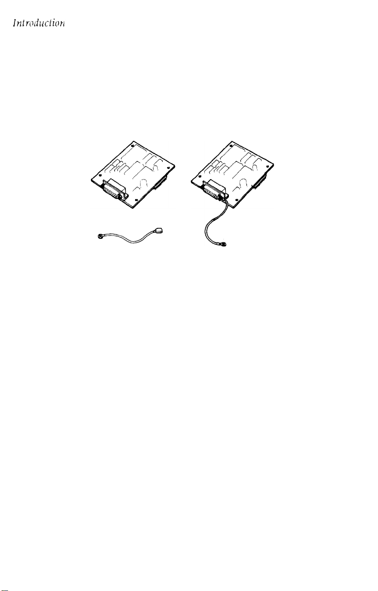
l Interface Boards
Optional interface boards are available to supplement the
printer’s built-m parallel and serial interfaces. Guidelines for
choosing the right interface and instructions on installing the
boards are given in Chapter 5.
About This Manual
This user’s manual provides fully illustrated, step-by-step
instructions on setting up and operating your Epson printer.
Finding your way around
l Chapter 1 contains information on unpacking, setting up,
testing, and connecting the printer. Be sure to read and follow
these instructions first. Inside the back flap of this manual are
illustrations of the printer in which all of the major parts are
identified.
l
Chapters 2 and 3 cover paper handling and general printer
operation. This important information is necessary for the day-
to-day operation of your printer.
4
Introduction
Page 13

Chapter 4 shows you how to get the most from your printer. It
includes advice on the use of software commands and graphics,
and creating your own user-defined characters. See Chapter 9
for a useful summary of printer commands.
If the printer does not operate properly or the printed results are
not what you expect, see Chapter 7 for troubleshooting
instructions.
Other chapters and the appendix contain information on printer
options, general maintenance, and specifications. You will also
find a glossary of printer terms.
At the back of this manual is a handy Quick Reference card that
contains the information you are most likely to need.
Note:
printer except for their widths. Therefore, the illustrations in this
guide show only the LQ-1050.
Conventions used in this manual
m
0
Notes contain important information and useful tips on the
operation of your printer.
The LQ-850, LQ-950, and LQ-1050 are basically the same
WARNINGS must
to your printer and computer.
CAUTIONS
I
.
your printer operates correctly.
should be followed carefully to ensure that
be followed carefully to avoid damage
Introduction 5
Page 14

Application Notes
Also included in the box with your printer is a booklet called
Application Notes. It contains information on using specific software
applications with your printer. Be sure to look at the booklet after
you set up your printer.
Where to Get Help
A network of authorized Epson dealers and service centers
throughout the United States provides customer support and
service for Epson products. Epson America provides product
information and toll-free support to its dealers and service centers.
Therefore, contact the business where you purchased your Epson
product to request assistance. If the people there do not have the
answer to your question, they can obtain it through Epson’s toll-free
dealer support program.
Epson is confident that this policy will provide you with the
assistance you need. If you need to find an Epson dealer or service
center in your area, please call our Consumer Information number
at l-800-922-8911.
6
Introduction
Page 15

Chapter 1
Setting Up the Printer
Unpacking the Printer.
Checking the Parts.
Removing the Protective Materials.
Choosing a Place for the Printer . . . . . . . . . . . . . . . . . . . . . .
Assembling the Printer.
Installing the Platen Knob
Installing the Ribbon Cartridge.
Attaching the Paper Guide.
Testing the Printer.
Plugging in the Printer
Running the Self Test
Checking the Operation
Connecting the Printer to Your Computer
The Parallel Interface
The Serial Interface
Setting Up Your Application Software
Choosing From a Menu
..............................
...............................
.................
.............................
.........................
....................
........................
.................................
............................
.............................
...........................
.............
.............................
...............................
................
...........................
1-2
1-2
1-3
1-8
1-10
1-10
1-11
1-15
1-18
1-18
1-19
1-27
1-30
1-31
1-32
1-34
1-34
Setting Up the Printer
l-l
Page 16
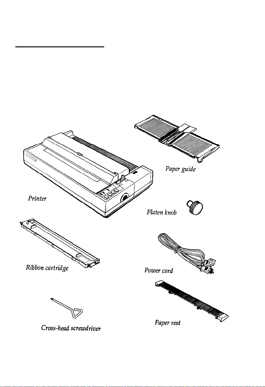
Unpacking the Printer
Checking the Parts
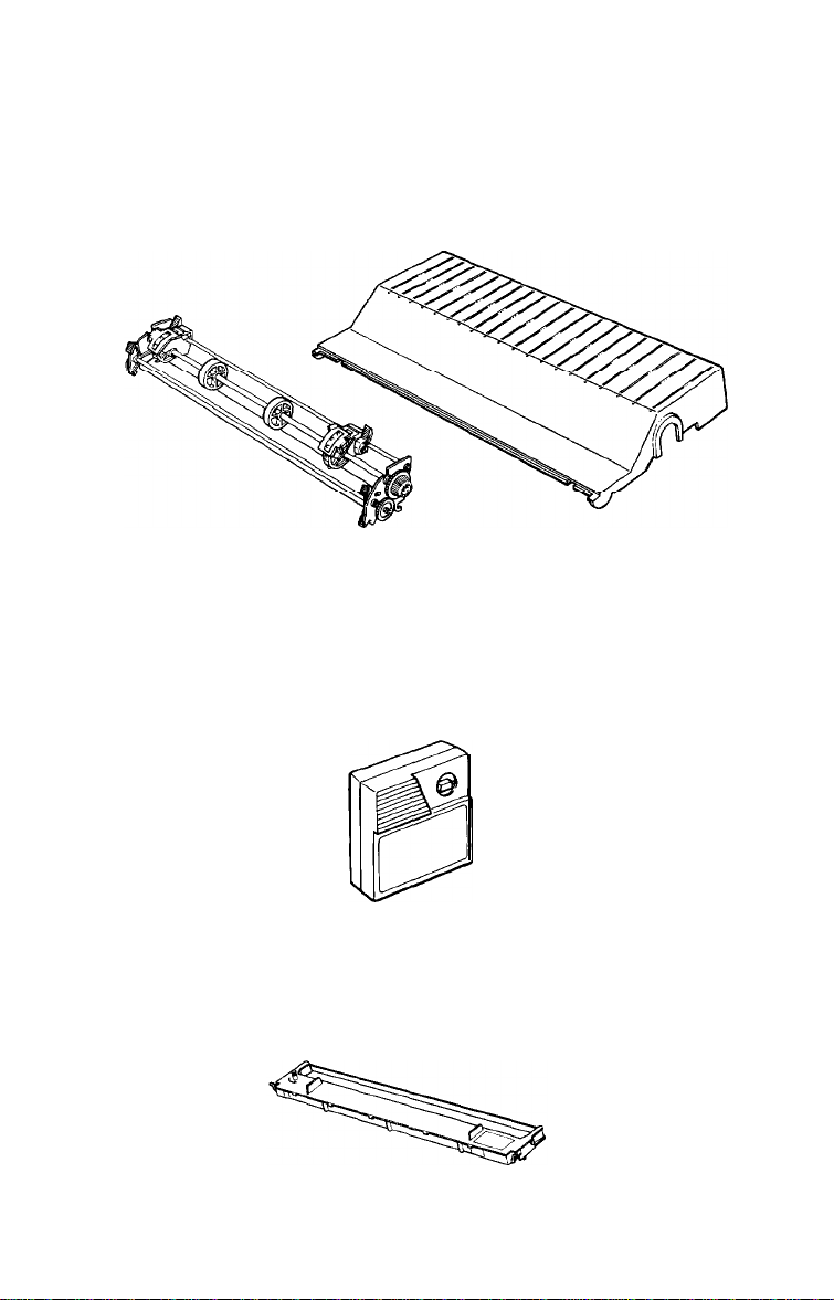
When you unpack the printer, make sure that you have all the parts
shown below and that none have been damaged.
\
Cross-head
1-2
sc~ewdtiver
Setting Up the Printer
Page 17
WARNING:
Several different versions of the printer have
been designed for different electrical standards. The label
on the back of the printer shows the power supply
voltage. If the voltage shown is not the correct voltage for
your country, contact your dealer. You cannot adjust the
printer for use on another voltage.
After removing the parts, save the packing materials in case you
ever need to transport your printer.
The ribbon cartridge that comes with the LQ-850 is #7753; #7767
comes with the LQ-950 and #7754 with the LQ-1050.
Removing the Protective Materials
The printer is protected during shipping by two locking brackets,
two locking tabs, and a print head protector. These protective items
must be removed before you turn on the printer. After removing
these items, store them with the other packing material in case you
ever need to transport your printer.
Remove the printer cover unit, which includes the printer cover
1.
and the paper guide cover.
Setting Up the Printer
1-3
Page 18
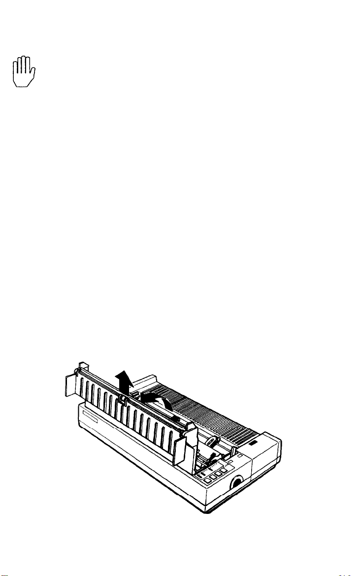
2.
Remove any pieces of white packing material you find inside the
printer.
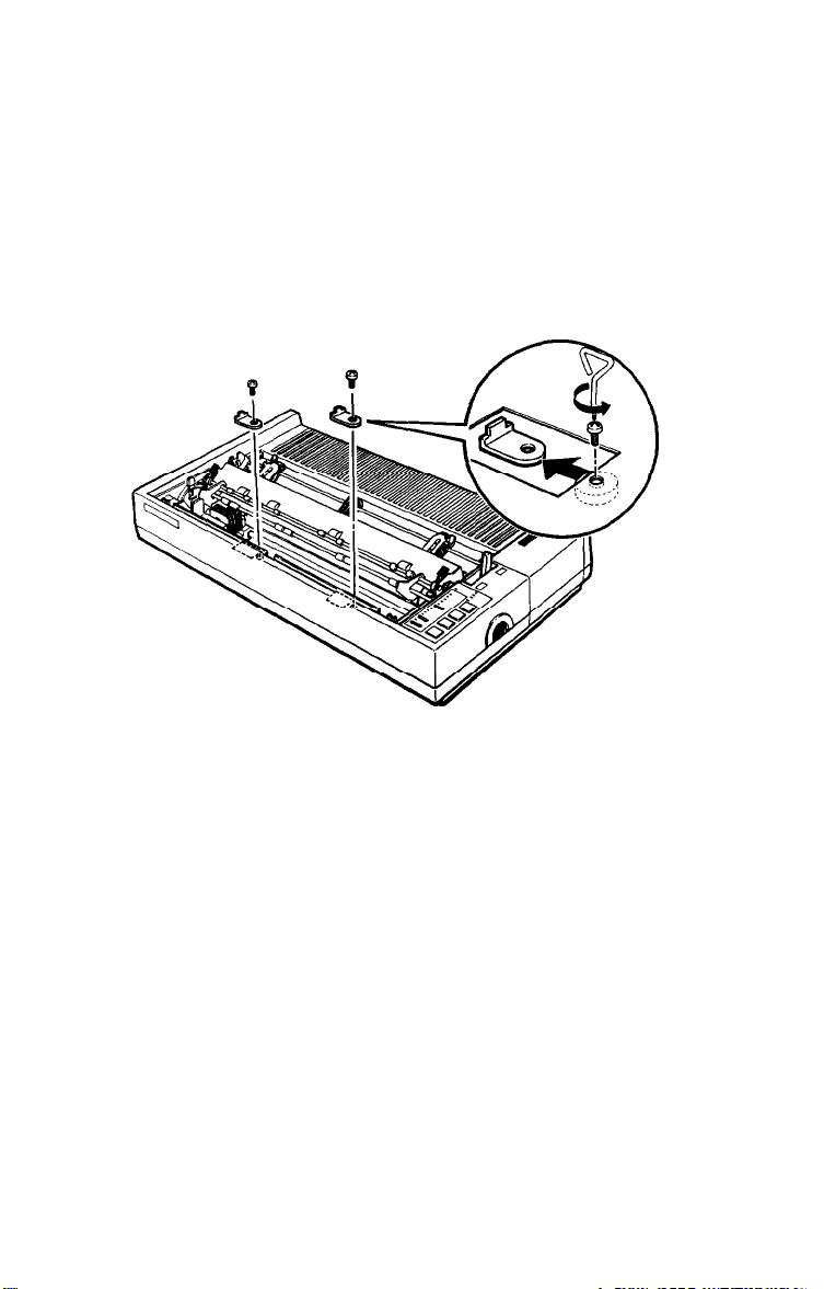
3.
Use the cross-head screwdriver that came with the printer to
unscrew and remove the two transport locking brackets. Look
straight down inside the printer to find the locking brackets. The
brackets are orange and their screws are red.
1-4
Setting Up the Printer
Page 19
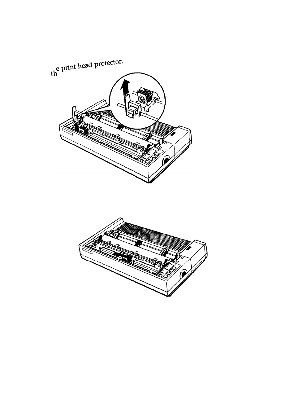
4. Remove
Slide the print head to the middle of the printer
5.
th
Setting Up the Printer
1-5
Page 20
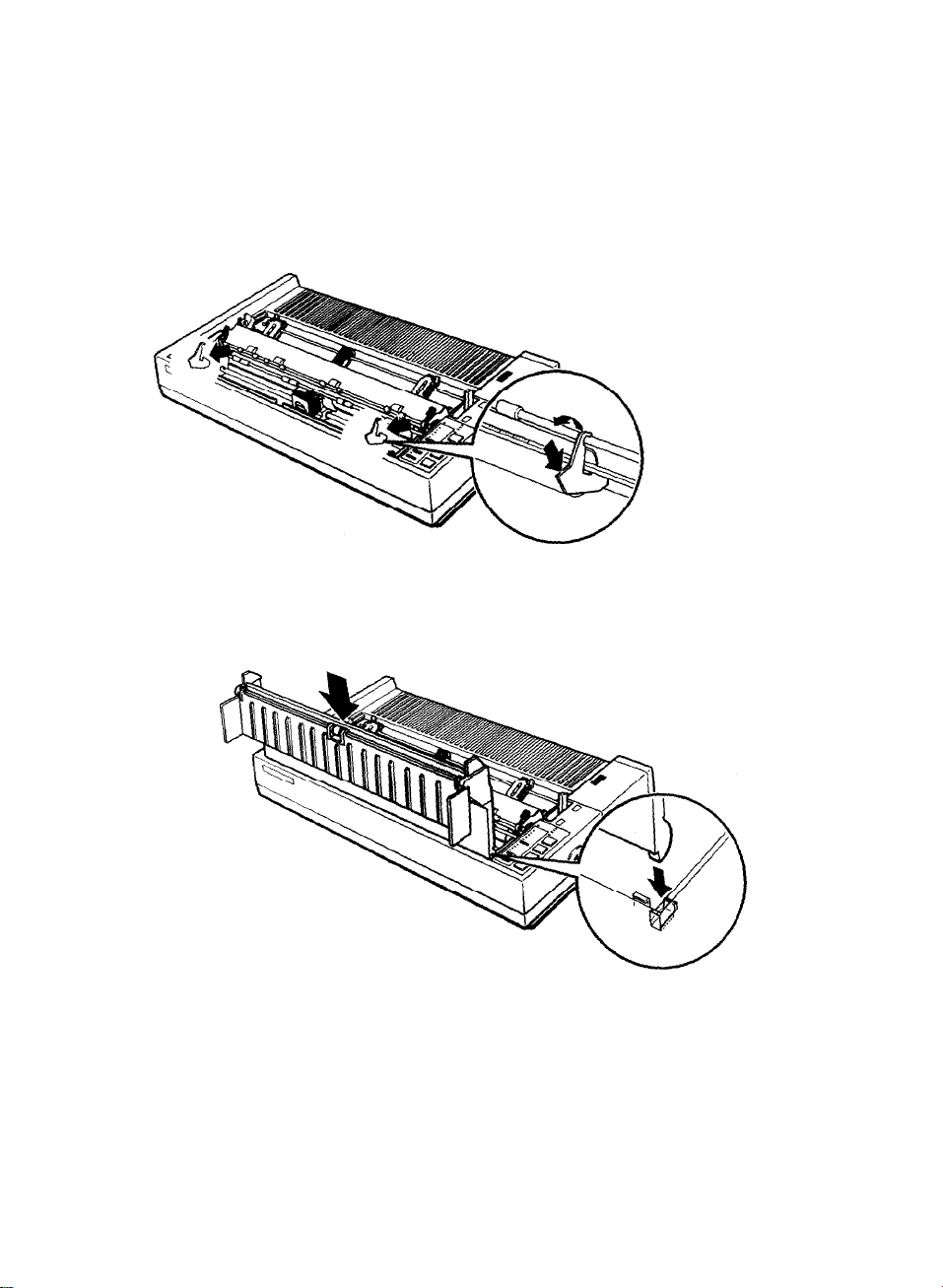
Remove the left
6.
Attach the printer cover unit.
7.
and right locking tabs.
1-6
Setting Up the Printer
Page 21
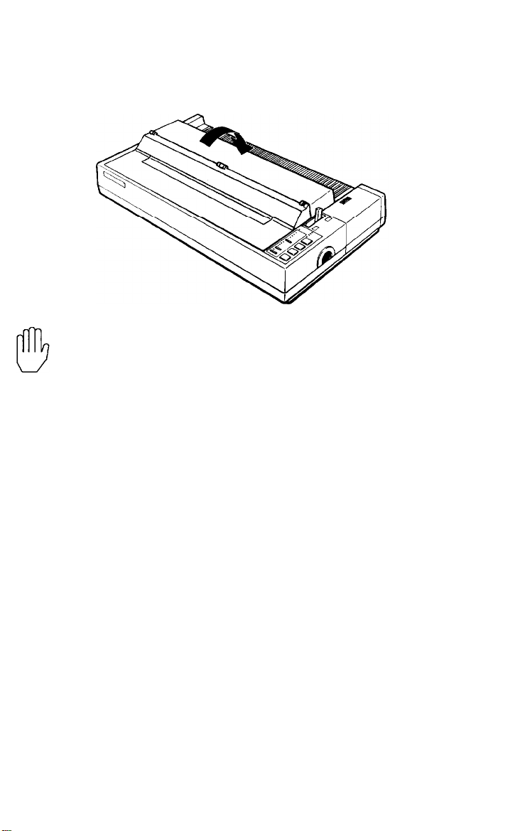
8.
Close the paper guide cover.
WARNING:
before you turn on the printer.
Be sure to remove all
protective
materials
Setting Up the Printer
l-7
Page 22

Choosing a Place for the Printer
There are several important things to consider when selecting a
place to set up your printer. Keep the following in mind:
Place the printer on a flat, hard, stable surface. A soft surface,
such as a padded counter or carpeted area, will block the
ventilation slots and may cause overheating.
Place the printer close enough to the computer for the printer
cable to reach.
Leave adequate room around the printer to allow for easy
printer operation and maintenance, and for unrestricted flow of
air around the printer.
Use a grounded outlet; do not use an adapter plug.
Avoid locations that are subject to direct sunlight, excessive
heat, moisture, or dust.
Avoid electrical outlets controlled by wall switches or automatic
timers. Accidental interruption of power can wipe out
information in both your computer’s memory and in your
printers memory.
Avoid using outlets that share a circuit with large motors or
electrical appliances; this could cause fluctuations in line
voltage.
Keep the entire computer system away from potential sources of
electromagnetic interference such as loudspeakers or the base
units of cordless telephones.
1-8
Setting Up the Printer
Page 23
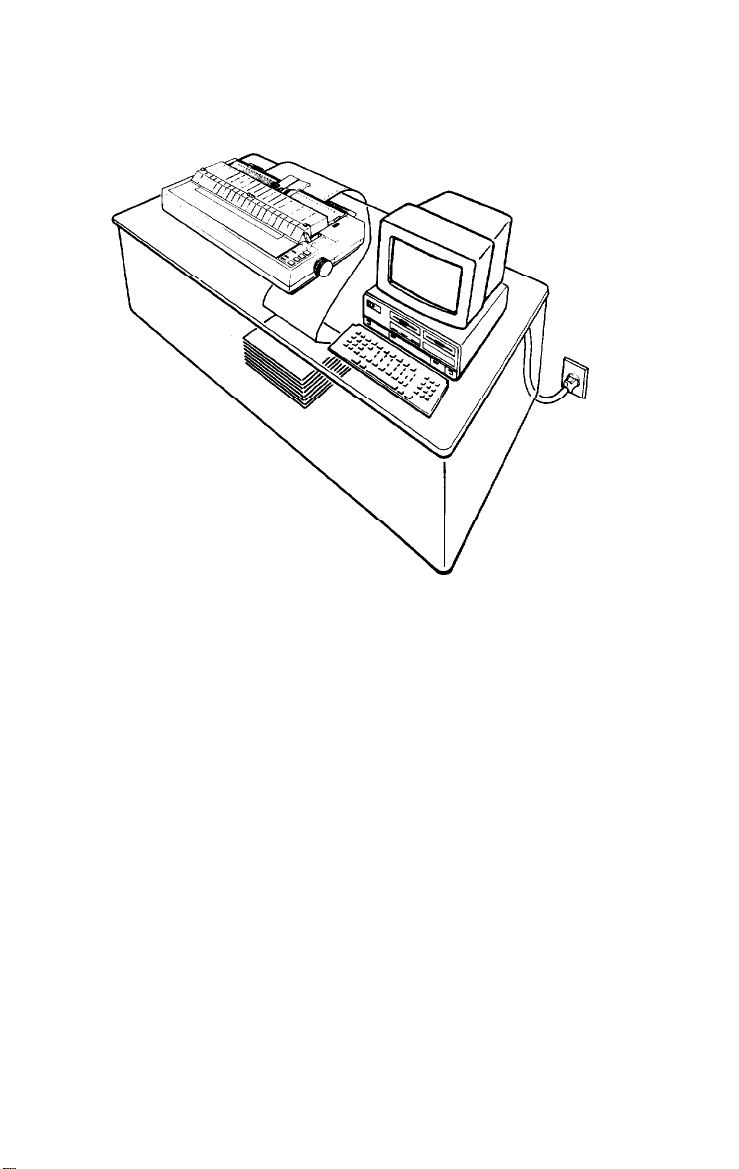
The illustration below shows a good printer arrangement.
Note: Before using a printer stand, read these requirements and
suggestions.
l
The stand should be able to support at least twice the weight of
the printer.
l
Never use a stand that supports the printer at an angle of
more than 15 degrees from horizontal.
l
With a cut sheet feeder, your printer must be kept level.
l If your paper supply is positioned below the printer stand,
make sure there is enough clearance to keep the paper from
catching on the underside of the stand. Also, make sure the
distance between the stand supports is wide enough for the
paper you are using.
l
Position your printer’s cables so that they do not interfere with
paper feeding. If possible, secure the cables to the printer stand.
Setting Up the Printer
1-9
Page 24
Assembling the Printer
After you’ve decided on the best place to set up your printer, the
next step is to install the platen knob.
Installing the Platen Knob
You use the platen knob to feed the paper manually in the event of a
paper jam or other paper feeding problem. The platen knob is packed
in an indentation in the printer’s white foam packing material.
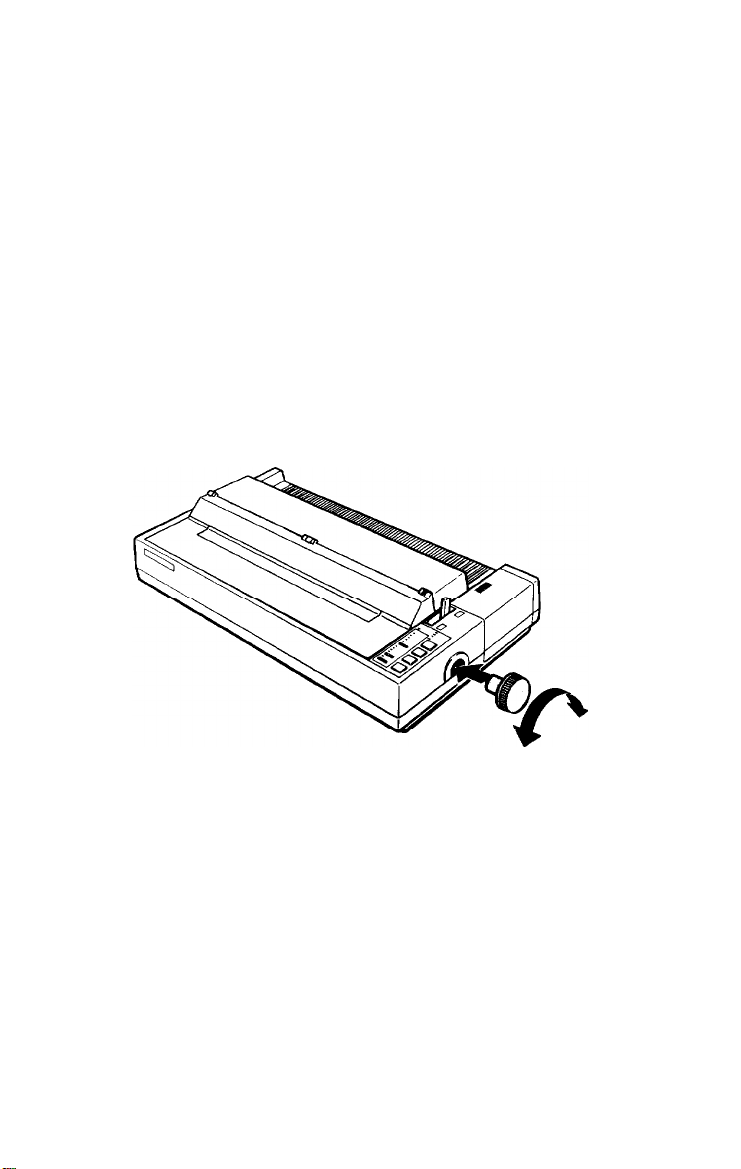
1.
Insert the platen knob into the hole on the printer’s side and
rotate it slowly until it slips onto the shaft.
1-10
Setting Up the Printer
Page 25
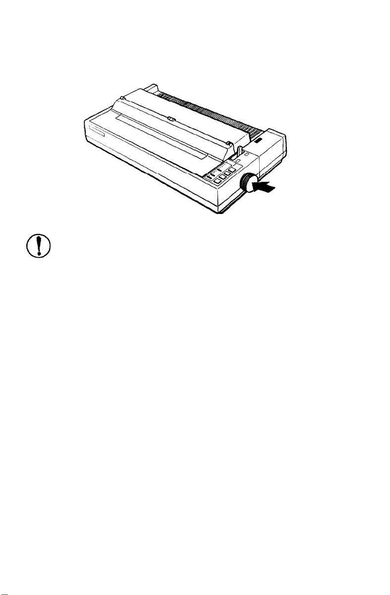
2.
Push firmly on the platen knob until it fits against the printer case.
CAUTION: Do not use the platen knob to adjust the
1
.
0
Installing the Ribbon Cartridge
Your printer’s ribbon cartridges are designed for easy installation
and removal. You install the standard ribbon cartridge and the
optional film ribbon cartridge in the same way. A standard ribbon
cartridge comes with your printer.
position of the paper. This interferes with the automatic
paper loading system and may cause a paper jam.
Install the ribbon cartridge as follows:
1.
Make sure the printer is turned off.
2.
Remove the printer cover unit.
Setting Up
the Printer
1-11
Page 26
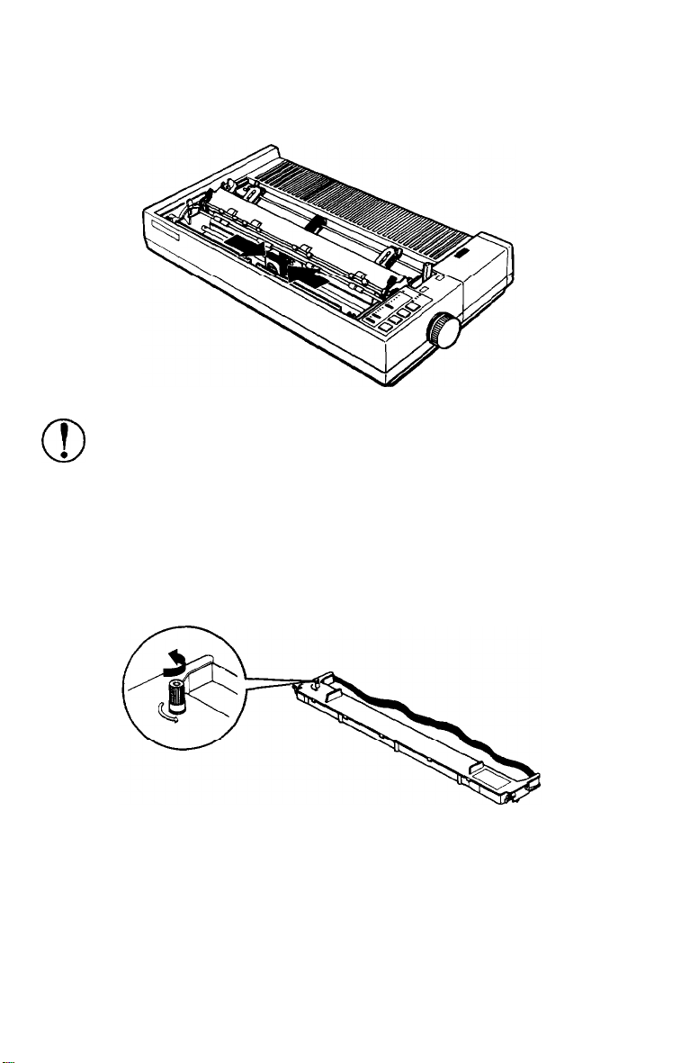
3.
Slide the print head to the middle of the printer.
CAUTION: Never move the print head while the printer is
I
.
0
4.
turned on because this can damage the printer. Also, if
you have been using the printer, the print head may be
hot; let it cool for a few minutes before touching it.
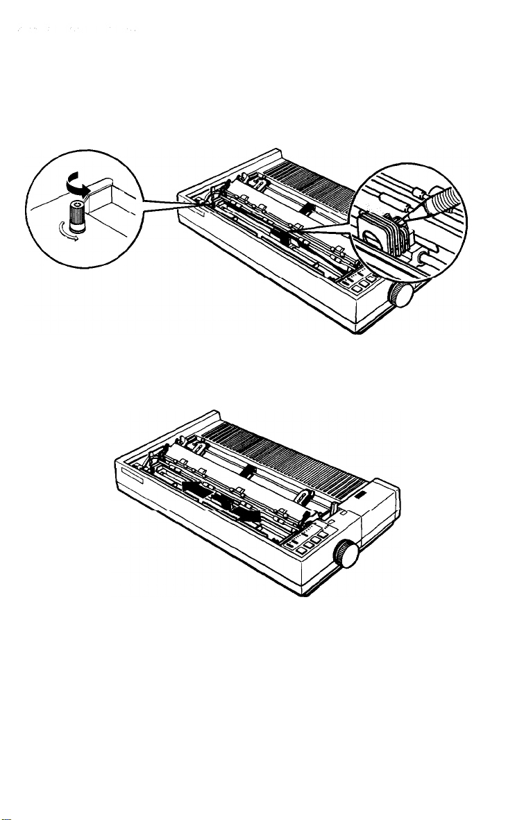
Turn the ribbon-tightening knob in the direction of the arrow.
This removes slack in the ribbon and makes it easier to install.
1-12
Setting Up the Printer
Page 27
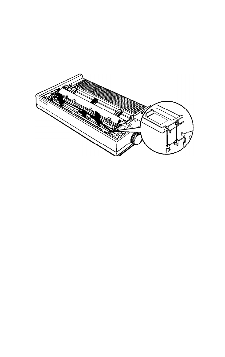
5.
Hold the ribbon cartridge by its black, fin-like handles with the
exposed ribbon away from you. (The LQ-850 ribbon cartridge
has only one handle.) Push the cartridge firmly into position,
making sure the plastic hooks fit into the slots inside the printer.
Note: Press lightly on both ends of the cartridge to make sure
the plastic hooks are properly seated.
Setting Up the Printer
1-13
Page 28
Use a pointed object, such as a ballpoint pen, to guide the ribbon
6.
between the print head and ribbon guide while you turn the
ribbon-tightening knob to help feed the ribbon into place.
Slide the print head from side to side to make sure it moves
7.
smoothly. Also check that the ribbon is not twisted or creased.
Make sure the paper thickness lever on the left is set to
position 2. See The Paper Thickness Lever in Chapter 2 if you
are printing on special paper.
1-14
Setting Up the Printer
Page 29
CAUTION:
Film ribbon cartridges must be used and
stored within the following temperature ranges:
Operation: 41°F to 95°F (5°C to 35°C)
Storage: -22°F to 104°F (-30°C to 40°C)
Storing and using a film ribbon at high temperatures
shortens the ribbon’s life expectancy, which is normally
200,000 characters (#7768 and #7769) or 300,000 characters
(#7770). If you continue to use the ribbon beyond its life
expectancy, printing suddenly becomes faint and the
ribbon may snap.
Attaching the Paper Guide
When you use single sheets, the paper guide helps to feed the paper
smoothly and efficiently into the printer. Attach the paper guide
using the following procedure.
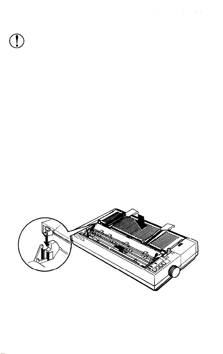
1.
Place the paper guide on the printer as shown below. Make sure
the back edge of the guide is even with the back of the printer.
Setting Up the Printer
1-15
Page 30
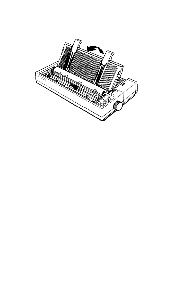
2.
Raise the paper guide until it locks into place.
Note: To lower the paper guide, lift up slightly to release it from
its locked position; then gently lower it down onto the printer.
1-16
Setting Up the Printer
Page 31

Attach the printer cover by fitting the hooks on the cover into
3.
the notches at the front of the printer and tilting the cover back
into place.
Close the paper guide cover.
4.
Setting Up the Printer
1-17
Page 32

Testing the Printer
Now that your printer is fully assembled, you can use its built-in
self test function to see that the printer is working correctly before
you connect it to a computer. You should perform this test to make
sure that your printer was not damaged during shipping and that
the ribbon is correctly installed.
Before running the self test, you need to connect the printer to an
electrical outlet and load a sheet of paper.
Plugging in the Printer
Make sure that the printer is turned off.
1.
Plug the power cable into a properly grounded electrical outlet.
2.
1-18
Setting Up the Printer
Page 33

Running the Self Test
The self test prints out the settings of the printer’s DIP switches and
the characters in the printer’s memory. The test can be run in either
high-speed draft, normal draft, or Letter Quality (LQ) mode.
You select the draft mode or Letter Quality mode, depending on
which button you hold down as you turn on the printer. You choose
between the high-speed draft and the normal draft mode by
changing your printer’s DIP switch settings. Your printers default
setting is high-speed draft mode. To run the test in normal draft
mode, see Setting the DIP Switches in Chapter 3 before following
the steps below.
The self test is 8 inches wide on the LQ-850,11 inches wide on the
LQ-950, and 14 inches wide on the LQ-1050.
CAUTION: Never run the self test using paper that is
I
.
0
Although the self test can be run with continuous paper, use singlesheet paper now because single-sheet loading is easier. Be sure to
use paper that is wide enough for the self test to print. If you need to
load continuous paper to print the self test, see Loading Continuous
Paper in Chapter 3.
narrower than 8.27 inches (210 mm) on the LQ-850,11
inches (279 mm) on the LQ-950, or 14 inches (360 mm) on
the LQ-1050. This prevents the print head from printing
directly onto the platen, which can damage the print head.
1.
Make sure the printer is turned off.
Setting Up the Printer
1-19
Page 34

2.
Push the paper release lever back to the single-sheet position.
While holding down the LINE FEED button (draft mode) or
3.
FORM FEED
The printer beeps several times and the
button (Letter Quality mode), turn on the printer.
POWER
and
PAPER OUT
lights come on.
l-20 Setting Up the Printer
Page 35

Move the left edge guide to the right or left until it rests against
4.
the triangular guide mark on the paper guide.
Adjust the right edge guide to match the width of your paper.
5.
Setting Up the Printer
1-21
Page 36

6.
Next, slide a sheet of paper down between the edge guides until
it meets resistance. After about two seconds, the printer loads
the paper automatically and then starts the self test.
A list of DIP switch settings is printed first, followed by a series
of characters. The self test continues until the paper runs out or
until you press the
ON LINE
button.
1-22
Setting Up the Printer
Page 37

7.
If the test results are satisfactory and you wish to stop the test,
press the
ON LINE
button.
If the test results are not satisfactory, see Checking the Operation
later in this chapter for
possible causes
and solutions.
Note:
To resume the test, press the
ON LINE
button
once
more.
Setting Up the Printer
1-23
Page 38

8.
To end the self test, press the
FORM FEED
paper that is still loaded. Then turn off the printer.
WARNING: After turning the power off, always wait at
least five seconds before turning it back on. Turning the
power on and off rapidly can damage the printer.
button to eject any
1-24
Setting Up the Printer
Page 39

Here are parts of typical self tests.
Normal draft mode
ABCDEFGHIJKLMNOPQRSTUVWXYZC\l^_'abcdefghijklm~
BCDEFGHIJKLMNOPQRSTUVWXYZC\I^
CDEFGHIJKLMNOPQRSTUVWXYZ[\]n-~abcdefghijklmnol
DEFGHIJKLMNOPQRSTUVWXYZ
EFGHIJKLMNOPQRSTUVWXYZ
[\I“ ‘abcdefghi
[\I” ‘abcdefghi
abcdefghijklmnc
jkl.mnop(
jklmnopql
FGHIJKLMNOPQRSTUVWXYZ[\]A-Tabcdefghijklmnopqr!
GtiIJKLMNOPQRSTUVWXYZC\lr’_‘abcdefghijklmnopq~-s
HIJKLMNOPQRSTUVWXYZ[\]A
'abcdefghijklmnopqrstl
IJKLMNOPQRSTUVWXYZ[\1^_Tabcdefghijklmnopqrstu~
JKLMNOPQRSTUVWXYZ [\]”
KLMNOPQRSTUVWXYZ [\] --y
LMNOPQRSTUVWXYZ [\I--‘abcdefghi
MNOPQRSTUVWXYZ [\]^-’
NOPQRSTUVWXYZ[\]^-‘abcdefghijklmnopqrstuvwxyz
OPQRSTUVWXYZ
PQRSTUVWXYZ
QRSTUVWXYZ C\] --‘-RSTUVWXYZ[\]“-‘abcdefghijklmnopqrstuvwxyz{;jSTUVWXYZ [\I”
TUVWXYZC\l^
UVWXYZ r\ry-
vwxYz[\]*-’
wxYz[\]XYZ[\]^
YZ [\]‘=-Tabcdefghi
z c \. 1
”
‘abcdefghi
[\I^
\I^.
‘abcdefghi
Tabcdefqhi.jklmnopqrstuvwxyz{
[\I -
[\I -
'abcdefghijklmnopqrstuvwxyz{
'abcdefghijklmnopqrstuvwxyz{!,
dbcdefghi jklmnopqrstuvwxyz{
‘abcdefghijklmnopqrstuvwxyz[:}+
'abcdefghijklmnopqrstuvwxyz{:}-
abcdefghi jklmnopqrstuvwxyz{
abcdefghijklmnopqrstuvwxyz{i]-
'abcdefghijklmnopqrstuvwxyz{i]-
Fabcdef ghi jkl.mnopqrstuvwxyz{
jklmnopqrstuvwxyz{
jklmnopqrstuvwxyz{
jklmnopqrstuvwxyz{:}+ !"#$%&'(
‘abcdefghi,jklmnopqrstuvl
abcdefghi jklmnopqrstuvw:
jklmnopqrstuvwx:
abcdef ghi jklmnopqrstuvwxy;
I
j”’ ! ”
!"#:
!"#$:
;
}”
!
‘I#$%;
t
I }” !
! “#$%&
i
j”
j”’ ! ‘I#$%&’
‘I#$%& ()
I
}’
!
Setting Up the Printer
1-25
Page 40

High-speed draft mode
I"#$%&'()*+,-./01234567S9:;(=>?@ABCDEFGHIJ~L~
!"#$%&'(py-
"#$%&'()*+,-./0123456789
./0123456787
#f$&&'()*+,-m/O123456789
$%&'()S-t
%&'(>*+,L
-./0123456789:
./OX23456789
a'()*+,-. /0123456789:;
'()*+,--
o*+,---
/0123456789:;
/0123456789
)*+,-m/O123456789
*+9--_
4. -
/0123456789
/PI 13x,1 GL7s2cl. - c -,
:;<=>?@ABCDEFGHIJKLMNOPQRSTUVW
<=>?@ABCDEFGHIJKLMNOPQRST
:;<=>?@ABCDEFGHIJKLMNOPQRSTL
:;<=>?@ABCDEFGHIJKLMNOPQRSTUV
3raARrnEFcl-d
:,<->?@ABCDEFGHXJKLM~
:;<=>?@ABCDEFGHXJKLMNC
:;<=>?@fWCDEFGHIJKLMNOF
;<=>?@ABCDEFGHIJKLMNOPCi
:;<=>?@ABCDEFGHIJKLMi'dOPOS
<=>?@ABCDEFGHI.JKLMNOPQRS
T
TKI MhlnclAR~-rI
Letter Quality mode
!"#$%&'()*+,-./0123456789:;<=>?@?ABCDEFGHIJKLM
'"#$%&'()*+,-./0123456789
i"#$%&'
#$%a'()*+,-
$%&'( )*t,-.
I%&'( )*+,-
I&'( I*+,-.
'( )$t,-.
'()*+,-
)*t,-.
*+,-.
+.--.
(
)*t,
-./0123456789 :;<=>?@ABCDEFGHIJKLMNC
./0123456789:;~=>?&iBCDEFGEIJKLMNOF
/0123456789:
./0123456789:;
/0123456789:;<=>?dhBCDABCDEFGEIJKLMNOPQRS
/0123456789:;
./0123456789:;
/0123456789:;
/0123456789:;
/nl7?Asifi7RO*
<=>?@ABCDEFGHIJKLMNOPQRST
<=>?@ABCDEFGHIJKLMNOPQRSTL
<=>?@ABCDEFGHIJKLMNOPQRSTW
~=>?tMBCDEFGEIJgLWTUW
l
(
=~?%AR~~R~GUT.lKT.MN~~~R~TIlVW~
:;<=>?QABCDEFGHIJKLMh
;<=>?@ABCDEFGHIJKLMNOPC
~=>?@ABCDEFGHIJlUMNO~
Ii/lrlV
Note: When using the optional cut sheet feeder, the first page of
the self test printout is slightly different. For details, see The Cut
Sheet Feeder in Chapter 5.
1-26
Setting Up the Printer
Page 41

Checking the Operation
If the self test does not print properly, check the control panel and
the print head area. If paper is jammed, turn off the printer. Then
remove the paper using the platen knob and load a new sheet. See
that all packing material and shipping restraints have been removed
from inside the printer. (You can also see Chapter 7 for further
information.)
Problem
The printer does not
print.
The printer sounds like
if is printing, but
nothing is printed.
The test did not print.
Solution
The ribbon may not be installed properly.
Turn off the printer, reinstall the ribbon
cartridge, and then tighten the ribbon by
turning the ribbon-tightening knob. Make
sure the ribbon passes between the print
head and ribbon guide.
The ribbon may be worn. Replace the
ribbon cartridge. See Replacing the
Ribbon in Chapter 6.
Turn off the printer and repeat the self
test. Make sure you hold down the
FORM FEED
or
LINE FEED
button the entire
time you are turning on the printer.
Turn off the printer and disconnect the
cable from the host computer. Try the self
test again.
If the printer still does not print the self
test correctly, contact your Epson dealer
or Epson authorized service center.
Setting Up the Printer
1-27
Page 42

Problem
The print is faint or
uneven.
Solution
Printed characters
have part missing at
the bottom as shown
here.
ABCD
The printout is faint.
Dots are missing in
the printed
characters or
graphics.
The ribbon cartridge may not be properly
installed. Remove the ribbon cartridge
and reinstall it; make sure the cartridge
hooks are inserted securely into the
printer.
The ribbon may be worn out. A worn
ribbon can damage the print head and
should be replaced. Install a new ribbon
cartridge as soon as possible. See
Replacing the Ribbon in Chapter 6.
The paper thickness lever may not be set
correctly for the paper you are using. Set
the paper thickness lever to match the
thickness of your paper. See The Paper
Thickness Lever in Chapter 2.
A line of dots is missing
in the printout.
1-28
Setting Up the Printer
The print head is damaged. Stop printing
and contact your Epson dealer to have the
print head replaced.
Page 43

Problem
Dots are missing in
the printed
characters or
graphics.
(continued)
Solution
Dots are missing in
random positions.
There is either too much slack in the
ribbon or the ribbon has come loose and
caught on something. Stop printing, turn
off the printer, and reinstall the ribbon
cartridge.
If the printer still does not print the self test correctly, contact your
Epson dealer.
Setting Up the Printer
1-29
Page 44

Connecting the Printer to Your Computer
Your printer has two separate interface connections: a parallel
interface and an RS-232C compatible serial interface. If you are not
sure which one is required by your computer, check your computer
manual for this information.
If you have a suitable shielded cable, you should be able to connect
to most computers immediately. If you have one of the few
computers that require a different type of interface, you need to
install an optional interface board. See The Interface Boards in
Chapter 5.
The parallel interface is the printer’s default setting. If you need to
use the built-in serial interface, be sure to change the DIP switch
setting as shown in Chapter 3.
1-30
WARNING:
the printer at one time. This may damage the printer.
Setting Up the Printer
Do not plug more than one interface cable into
Page 45

The Parallel Interface
Connect the parallel interface cable as described below:
Make sure that both your printer and computer are turned off.
1.
Plug the cable connector securely into the printer.
2.
Squeeze the wire clips together until they lock in place on either
3.
side of the connector.
Setting Up the Printer
1-31
Page 46

4.
If your cable has a ground wire, connect it to the ground screw
beneath the interface connector.
5.
Plug the other end of the cable into the computer. If there is a
ground wire at the computer end of the cable, attach it to the
ground connector at the back of the computer.
The Serial Interface
Connect the serial interface cable as described below:
1.
Make sure both your printer and computer are turned off.
1-32
Setting
Up
the Printer
Page 47

2.
Plug the connector securely into the printer.
WARNING:
the printer at once. This may damage the printer.
3.
Plug the other end of the cable into the computer.
Do not plug more than one interface cable into
Setting Up the Printer
1-33
Page 48

Setting Up Your Application Software
Now that you have set up and tested the printer, you should make
sure that it works with your application programs.
Most application programs let you specify the type of printer you
are using so that the program can take full advantage of the
printer’s features. Many of these programs provide an installation or
setup menu that presents a list of printers to choose from.
If your application program has a printer selection menu, use the
instructions below.
Choosing From a Menu
Because the family of Epson printers shares a great many
commands, you can use an application program even if it does not
list the LQ-850, LQ-950, or LQ-1050 on its printer selection menu. If
the printer is not listed, choose one of the following printers. They
are listed in order of preference.
LQ-850 (LQ-950, LQ-1050)
LQ-800 (LQ-1000)
LQ-510/LQ-500
LQ-1500
If none of these printers is listed, select the first one available on the
following list: LQ, EX, FX, LX, RX, MX, Epson printer, Standard
printer, Draft printer.
To use all of the features of the printer, however, it is best to use a
program with the LQ-850, LQ-950, or LQ-1050 on its menu. If your
program does not list the printer, contact the software manufacturer
to see if an update is available that supports your model.
1-34
Setting Up the Printer
Page 49

Chapter 2
Paper Handling
Using Single Sheets
Loading Paper
Reloading During Printing
Using Continuous Paper
Positioning Your Continuous Paper Supply. .........
Loading Continuous Paper ........................ 2-7
Switching Between Continuous and Single Sheets ...... 2-16
Switching to Single Sheets ......................... 2-16
Switching Back to Continuous Paper. ...............
Printing on Special Paper. ...........................
The Paper Thickness Lever ........................
Multi-part Forms .................................
Labels ..........................................
Envelopes ....................................... 2-32
.................................
...................................
........................ 2-5
............................
2-2
2-2
2-6
2-6
2-21
2-25
2-25
2-29
2-30
Paper Handling 2-1
Page 50

Using Single Sheets
Your printer can accommodate single sheets up to a maximum
width of 10.1 inches (257 mm) on the LQ-850,13.0 inches (330 mm)
on the LQ-950, or 14.3 inches (364 mm) on the LQ-1050.
If you do most of your printing on single sheets, you may find it
more convenient to install the optional cut sheet feeder. This option
automatically inserts a new sheet and can hold up to 150 pages. For
more details, see Chapter 5.
Loading Paper
1.
Make sure the printer is turned off.
2.
Push the paper release lever back to the single-sheet position.
This position is marked by the icon shown below.
Note: For normal use, the paper thickness lever is set to position
2. See The Paper Thickness Lever later in this chapter if you are
printing on special paper.
2-2
Paper Handling
Page 51

3.
Turn on
the
printer. The
POWER
and
PAPER OUT lights come
on.
Note: Do not insert paper in the printer before turning on the printer.
4.
Move the left edge guide until it rests against the guide mark.
(You may want to change this position later, depending on the
margin settings of your application program.)
Paper Handling 2-3
Page 52

5.
Adjust the right edge guide to match the width of your paper.
6.
Slide the paper down between the edge guides until it meets
resistance and the
PAPER OUT
light goes off. After about two
seconds, the printer loads the paper automatically, and is set to
ON LINE so that it can accept data from your computer.
2-4
Paper Handling
Page 53

WARNING: Never advance the paper using the platen
knob except in
the case of a paper jam or other paper feed
problem. Using the platen knob while the printer is on
may damage the printer and affect the loading and short
tear-off positions.
Note: If the platen turns without loading the paper, press
ON LINE button to take the printer off line and completely remove
the
the paper. Then re-insert the paper more firmly.
If you need to adjust the position of the paper after it is loaded, use
the micro-adjustment feature described in Adjusting the Loading
Position in Chapter 3.
To eject the paper, press
line; then press
the LOAD/EJECT
the ON LINE button to take the printer off
button.
You are now ready to begin printing.
Reloading During Printing
When you print a document of more than one page using single-
sheet paper, the printer stops printing when it reaches the bottom of
the page. When
this happens, the ON LINE light either goes off
automatically or remains on, depending on your application
program software. If the
do
is
press the
Once the ON LINE
ON LINE
printed (if necessary, press
ON LINE light remains on, the first thing you
button to take the printer off line.
light is off, remove
the FORM FEED
the
sheet
button to eject
that
has just been
the
page).
Then load a new sheet to start printing the next page and follow any
additional prompts from your software.
Paper Handling 2-5
Page 54

Using Continuous Paper
The tractor built into your printer is remarkably easy to load and
operate. Its low-profile design takes up little space and can handle
paper up to 10.0 inches or 254 mm wide on the LQ-850, up to 12.0
inches or 305 mm on the LQ-950, and up to 16.0 inches or 406 mm
wide on the LQ-1050.
Positioning Your Continuous Paper Supply
An important consideration for achieving smooth and trouble-free
paper feeding is the position of your paper supply.
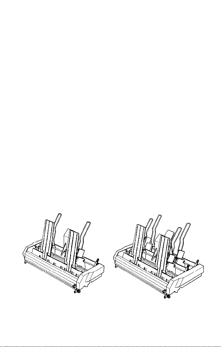
Three ways of positioning your printer and continuous paper
supply are shown below.
2-6
Paper Handling
Page 55

Be sure to align the paper supply with the paper loaded in the
tractor so that the paper feeds smoothly into the printer.
Loading Continuous Paper
1.
Be sure that the printer is turned off.
2.
Pull the paper release lever forward to the continuous paper
position. This position is marked by the icon shown in the
illustration below.
Paper Handling 2-7
Page 56

Open the paper g
3.
Attach the paper rest
4.
uide cover and remove the paper guide.
2-8
Paper Handling
Page 57

Release the sprocket units by pulling the sprocket lock levers
5.
forward as shown below.
6.
Slide the left sprocket unit all the way to the left and press the
lever back to lock it in place.
Paper Handling 2-9
Page 58

Note: The first printable column position is indicated by the mark
shown in the illustration below.
7.
Slide the right sprocket unit so that it roughly matches the width
of your paper, but do not lock it.
2-10
Paper Handling
Page 59

8.
Move the paper support midway between the two sprocket
units.
9.
Open both sprocket covers.
0
CAUTION:
1
.
clean, straight edge before inserting it into the printer.
Make sure that the first sheet of paper has a
Paper Handling
2-11
Page 60

10. Fit the first four holes in the paper over the pins of both
sprockets.
11. Close the sprocket covers.
2-12
Paper Handling
Page 61

12. Slide the right sprocket unit to a position where the paper is
straight and has no wrinkles. Then lock it in place.
13. Reattach the paper guide on top of the paper as shown below.
Then slide the edge guides together so that they meet at about
the middle of the paper’s width.
0
CAUTION: When using continuous paper, always make
I
.
sure that the paper edge guides are pushed together in the
middle of the paper guide.
Paper Handling
2-13
Page 62

Note: For normal use, the paper thickness lever is s
2. If you are using special paper, see The Paper Thic
et to position
kness Lever
later in this chapter for details.
14. Close the paper guide cover and turn on the printer.
15.
Press the
LOAD/EJECT
button to feed paper to the loading
position.
2-14
Paper Handling
Page 63

16. Press the
accept data.
The printer remembers the loading position and advances each page
to the same position. If you need to adjust the loading position, use
the micro-adjustment feature. See Adjusting the Loading Position in
Chapter 3.
I
.
0
ON LINE
CAUTION: Never adjust the loading position using the
platen knob and never turn the platen knob while the
printer is turned on.
button to set the printer on line
so that
it can
When using continuous paper, you can choose the short tear-off
feature to give you added paper handling capabilities. This feature
makes it easier to detach printed pages and saves the blank pages
that are usually lost between printing jobs. See Using Short Tear-off
in Chapter 3 for details.
Paper Handling
2-15
Page 64

-
Switching Between Continuous and Single Sheets
Even with continuous paper loaded in the printer, the SmartPark
feature allows you to easily switch to single-sheet printing without
removing the continuous paper from the tractor.
Switching to Single Sheets
To switch from continuous paper to single sheets, follow the steps
below.
1.
If the printer is on line, press the ON LINE button to set the printer
off line. Open the paper guide cover.
2-16
Paper Handling
Page 65

Tear off any outgoing sheets. If the paper has advanced past the
2.
print head, you need to press the FORM FEED button to advance
your document to a point where it can be easily removed.
CAUTION: Make sure you tear off your printed document
I
.
0
before pressing the
several pages at a time may result in a paper jam. This is
especially true for narrow paper (less than 6 inches or
152.4
mm wide).
LOAD/EJECT
button. Reverse-feeding
Paper Handling
2-17
Page 66

Press the
LOAD/EJECT
button to feed the continuous paper
backward out of the printer and into the standby position. The
paper is still attached to the tractor but no longer in the paper
path. The
PAPER OUT
light comes on when the paper is
completely out of the paper path.
2-18
CAUTION: Pressing
the LOAD/EJECT
button once may not
feed the paper far back enough to reach the standby
position.
the
continuous paper, you can press the
If the PAPER OUT light
LOAD/EJECT
button again. With normal-width
does not come on, press
LOAD/EJECT
button up
to three times. If, however, you are using narrow paper
(between 4 and 6 inches or 101.6 and 152.4 mm) you can
press
the LOAD/EJECT
button
only once.
Also, do not use
this button to eject labels.
WARNING: Never feed labels backward through the
printer. Labels can easily come off the backing sheet and
jam the printer.
Paper Handling
Page 67

Push the paper release lever back to the single-sheet position.
4.
5.
Lift the
paper
Paper Handling
2-19
Page 68

6.
Move the left edge guide until it rests against the guide mark.
Adjust the right edge guide to match the width of your paper.
7.
Close the paper guide cover.
2-20
Paper Handling
Page 69

8.
Slide a sheet of paper down between the edge guides until it
meets resistance and the
PAPER OUT
light goes off. After about
two seconds, the printer loads the paper automatically and sets
itself
ON LINE.
Switching Back to Continuous Paper
It is also easy to switch back to printing with continuous paper.
Before switching to continuous paper, make sure that the single
sheet is ejected and the printer is off line.
Paper Handling
2-21
Page 70

1.
Open the paper guide cover.
2.
Lift up slightly on the paper guide and then lower it onto the
back of the printer.
2-22
Paper Handling
Page 71

Slide the left and right edge guides together so that they meet at
3.
about the middle of the continuous paper's width.
Pull the paper release lever forward to the continuous paper
4.
position, then close the paper guide cover.
Paper Handling
2-23
Page 72

5.
Press
the LOAD/EJECT
button to feed the continuous paper to the
loading position. Then, press the ON LINE button to set the
printer on line so that it can accept data.
2-24
Paper Handling
Page 73

Printing on Special Paper
In addition to printing on single sheets and continuous paper, your
printer can also print on a wide variety of paper types, including
multi-part forms, labels, and envelopes.
If you are printing preprinted or multi-part forms or labels, it is
recommended that you use the optional pull tractor. See The Pull
Tractor in Chapter 5.
Before printing on special types of paper, you need to change the
paper thickness setting.
WARNING:
envelopes, make sure that your application program
settings keep the printing entirely within the printable
area.
For multi-part forms and labels you should not print any
closer than one-half inch (38 mm) from either side of the
paper.
For information on the printable area for envelopes, see
Envelopes later in this chapter.
The Paper Thickness Lever
To accommodate various thicknesses of paper, the printer is
equipped with a paper thickness lever that can be set to eight
positions. These positions are identified by a scale on the printer
next
to the lever.
When printing on multi-part forms, labels, or
Paper Handling
2-25
Page 74

Note: For normal use, set the paper thickness lever to position 2
on the scale.
If you have installed the optional film ribbon cartridge, and you
want to use the single sheets or continuous paper, set the paper
thickness lever to position 1.
The following table gives you general guidelines for selecting the
right paper thickness lever position for the type of paper you are
using:
Note: If the lever is set to position 4 or higher, the printing speed may be reduced
slightly.
2-26
Paper Handling
Page 75

To change
1.
Make sure that the printer is turned off. Then remove the printer
the
paper thickness
setting, follow these steps.
cover.
WARNING: If the printer has just been in use, the print
head may be hot. Be careful not to touch it.
Paper Handling
2-27
Page 76

2.
Select the paper thickness you want according to the table
below. For normal use, the lever should always be set to
position 2 on the scale.
3.
Reattach the printer cover unit.
2-28
Paper Handling
Page 77

To help you check the position of the paper thickness lever, the
orange
MULTI-PART
light on the control panel comes on if the
lever is set to position 4 or higher.
WARNING:
Always return the lever to position 2 when
you go back to printing on ordinary paper. Continuous
printing with the lever set at a position higher than 2 can
shorten the life of the print head.
Printing past the edge of envelopes, multi-part forms,
labels, or thicker-than-normal paper can damage the print
head.
Multi-part Forms
With the built-in tractor unit, your printer can print on continuous
multi-part forms. You can use multi-part forms that have up to four
parts including the original. Make sure you set the paper thickness
lever to the proper position.
Except for the paper thickness lever setting, you load multi-part
paper the same way as continuous paper. For details, see Loading
Continuous Paper in this chapter. Also see Adjusting the Loading
Position and Page Length in Chapter 3.
Paper Handling
2-29
Page 78

When you set the paper thickness lever to position 4 or above, the
MULTI-PART light comes on and the printer reduces its printing
speed.
CAUTION:
I
.
0
Labels
If you need to print labels, always use labels mounted on a
continuous backing sheet with sprocket holes for use with a tractor.
Do not try to print labels as single sheets because labels on a shiny
backing sheet almost always slip a little.
You load labels the same way that you load continuous paper
except that the paper thickness lever must be adjusted for printing
labels. See Loading Continuous Paper earlier in this chapter. For the
correct paper thickness setting, see The Paper Thickness Lever
earlier in this chapter.
sheet feeding system or the optional cut sheet feeder.
WARNING: Never feed labels backward through the
printer. Labels can easily peel off the backing and jam the
printer. Therefore, never use the
eject labels. Also, never use the short tear-off function with
labels. (Be sure to set DIP switch 2-7 to OFF.) If a label
does become stuck in the printer, contact your Epson
dealer.
Do not use multi-part forms with the single-
LOAD/EJECT
button to
2-30
Because labels are especially sensitive to temperature and
humidity, always use them under normal operating
conditions. Don’t leave labels loaded in the printer
between jobs; they curl around the platen and may jam
when you resume printing.
Paper Handling
Page 79

To eject labels from the printer, follow these steps:
1.
Open the paper guide cover and remove the paper guide.
2.
Tear off the sheet of labels at the perforation behind the push
tractor.
Paper Handling
2-31
Page 80

3.
Press
the
ON LINE
button to set
the
printer off
line.
Then press
the
FORM FEED button to eject the labels.
Envelopes
You can feed envelopes individually using the single-sheet loading
feature. Before loading envelopes, adjust the position of the paper
thickness lever according to the Paper Thickness Lever table earlier
in this chapter. For details on paper handling, see Using Single
Sheets earlier in this chapter. See Chapter 5 for a description of how
to use envelopes with the optional cut sheet feeder.
2-32 Paper Handling
Page 81

When manually feeding an envelope, you may have to push it down
slightly to get it to feed properly. After about two seconds, the
envelope loads automatically.
0
CAUTION:
I
.
the next page. The print head must not go past the left or
right edge of the envelope or other thick paper. Make sure
that your application program page setup keeps the
printing entirely within this printable area.
Always keep the longer side of the envelope horizontal.
If you use No. 6 envelopes, make sure the left edge guide
is aligned with the arrow on the paper guide.
The printable area for envelopes is shown on
Paper Handling
2-33
Page 82

0.33
inch
(8.5
mm) or more
0.87 inch
(22
mm) or more
CAUTION:
I
.
0
To make sure that the printing fits within the printable area, always
print a test sample using a normal sheet of paper before printing on
envelopes.
temperature (41°F to 95°F or 5°C to 35°C).
Envelope printing is available only at normal
2-34
Paper Handling
Page 83

Chapter 3
Using the Printer
Operating the Control Panel . . . . . . . . . . . . . . . . . . . . . . . . .
Setting the DIP Switches.
Changing a DIP Switch Setting.
The DIP Switch Tables
The DIP Switch Functions
Page Length . . . . . . . . . . . . . . . . . . . . . . . . . . . . . . . . . . . . . . .
Skip Over Perforation. . . . . . . . . . . . . . . . . . . . . . . . . . . . . . .
Adjusting the Loading Position.
The Loading Position
Using Micro-adjustment.
Using Short Tear-off
Adjusting the Tear-off Position
Selecting Typestyles
Character Fonts
Character Spacing
Condensed Mode
..................................
............................
....................
............................
.........................
......................
.............................
..........................
................................
.....................
................................
................................
................................ 3-25
3-2
3-6
3-6
3-7
3-10
3-11
3-12
3-14
3-14
3-15
3-17
3-19
3-21
3-21
3-24
Selecting an International Character Set . . . . . . . . . . . . . . .
Selecting a Graphics Character Set . . . . . . . . . . . . . . . . . . . . 3-28
Choosing a Character Table. . . . . . . . . . . . . . . . . . . . . . . . . .
Using the Data Dump Mode . . . . . . . . . . . . . . . . . . . . . . . . .
Using the Printer
3-26
3-31
3-35
3-1
Page 84

The indicator lights give you the current status of the printer. The
buttons and paper handling functions let you control many of the
printer settings.
Lights
0
0
0
MULTI-PART0 PAPER
0
0
SANS SERIF
FORM FEED
LINE FEED
LOAD / EJECT
OCCNDENSED
IL
POWER
READY
ON LINE
cl
cl
OUl
e
0)
BIN1
0) 0
BIN;
MULTI-PART
(orange)
On when the paper thickness
lever is set to position 4 or
higher. (For regular paper, this
light should not be on.) When
this light is blinking, the microadjustment function can be
used.
POWER
On
(green)
when the
POWER
switch is
on and power is supplied.
READY
(green)
On when the printer is ready to
accept input data. Flickers
during printing.
PAPER OUT
(red)
On when the printer is out of
paper or when continuous
paper is in the standby position.
3-2 Using the Printer
ON LINE
(green)
On when the printer is on line
and ready to accept data.
Page 85

Buttons
0
POWER
0
READY
0
MULTI-PART 0 PAPER OUT
SelecType
0
SANS SERIF
OCGNDENSED
El,
-OAD/ EJECT
cl
1))
BIN ’
0) 11
BIN;
BIN 1/BIN 2
When the printer is on-line,
press this button to select
either bin 1 or bin 2 of the
double-bin cut sheet feeder.
The beeper sounds once if
you select bin 1 and twice if
ON LINE
This button controls the printer’s
on line and off line status. Press
this button to put the printer on
line or to take it off line. When the
printer is on line, the
ON LINE light
is on and the printer can receive
and print data from the computer.
FORM FEED
When the printer is off line, press
this button to eject a single sheet
of paper or to advance continuous
paper to the top of the next page.
LINE FEED
When the printer is off line, press
this button to advance the paper
one line, or hold it down to
advance the paper continuously.
LOAD/EJECT
When the printer is off line, press
this button to feed paper to the
loading position or to eject paper
that is already loaded. Paper is
ejected forward if the paper
release lever is set to the singlesheet position and backward (out
of the paper path) if the release
lever is set to the continuous
paper position.
*
Using the Printer
3-3
Page 86

SelecType
0 MULTtPART0
SelecType 1
FONT
0
DRAFT
0 ROMAN
0 SANS SERIF
0 SLOT A
0
SLOT
B
I[
0 POWER
0 READY
PAPER OUT
nON LINE
cl
FORM FEEI
FONT
Press this button to select LQ
ROMAN,
LQ
SANS SERIF, DRAFT
mode, or a cartridge font (if
installed). The two orange
indicator lights show the font you
select. See Selecting Typestyles
later in this chapter.
PITCH
Press this button to select the
character spacing. You can choose
10 CPI, 12 CPI, 15 CPI, or PS
(proportional spacing). The
orange indicator light shows the
spacing you select. You cannot
select proportional spacing with
draft mode. (Draft mode
overrides proportional spacing.)
CONDENSED
Press this button to turn the
condensed mode on and off. The
orange indicator light is on when
the printer is in the condensed
mode. In the condensed mode, all
characters are printed at
approximately 60 percent of their
normal width. You cannot select
condensed mode with a pitch of
15 cpi.
3-4
Using the Printer
Page 87

Other control panel features
The control panel of your printer also gives you access to several
special functions.
Self test:
Micro-adjustment:
Data dump:
Both a draft and Letter Quality self test
function are built into the printer. The self test
printout lets you check the current DIP switch
settings and operating status of the printer.
You can start the printer’s self test by holding
down the
the
LINE FEED
FORM FEED
button (for draft mode) or
button (for Letter Quality
mode) while turning on the printer. See
Running the Self Test in Chapter 1 for more
information.
By pressing
the FORM FEED
or
LINE FEED
button immediately after loading paper or
when using short tear-off, you can make fine
adjustments to the loading and short tear-off
positions. These positions can only be
adjusted while the
MULTI-PART
light is
blinking. See Adjusting the Loading Position
and Using Short Tear-off later in this chapter.
By holding down both the
FORM FEED
buttons while you switch on the
LINE FEED
and
printer, you turn on the data dump mode.
This feature allows advanced users to locate
the source of communications problems
between the computer and printer. See Using
the Data Dump Mode later in this chapter for
more information.
Input buffer control:
To enable or disable the input buffer, press the
LOAD/EJECT
button while you turn on the
power. The beeper sounds once if the input
buffer is disabled and twice if it is enabled.
Using the Printer
3-5
Page 88

Setting the DIP Switches
The printer has two sets of DIP (Dual Mine Package) switches
located on the back panel. By changing the settings of these
switches, you can control various printer features, such as the
character set and page length. The new settings become effective
when you turn on, reset, or initialize the printer.
Changing a DIP Switch Setting
To change a DIP switch setting, follow these steps:
1.
Turn off the printer.
2.
Locate the DIP switches on the back of the printer.
3.
Use a pointed object, such as a pen, to change the DIP switch
settings. A DIP switch is on when it is up, and off when it is
down.
The new DIP switch settings take effect when you turn the printer on.
3-6
Using the Printer
Page 89

The DIP Switch Tables
The tables below describe the DIP switch settings. The shaded
settings are the preset factory settings.
DIP Switch 1
SW Description
1-1
International character set/
1-2
Graphics character set
1-3
1-4 Character table
1-5
Print direction for graphics
l-6 High-speed draft
l-7 Cut sheet feeder mode
l-8 Skip over perforation
DIP Switch 2
SW Description
2-l
Page length selection
2-2
I
I
2-3 Interface type/parity
2-4
ON OFF
See table 1, 4
Graphics Italics
Unidir. Bidir.
OFF ON
ON
ON
ON OFF
See table 5
I
See table 2
OFF
OFF
I
Note:
The factory settings for DIP switches 1-1 to 1-3, 1-4, 2-1, and
2-2 vary depending on the country and are not shown in the
tables.
Using the Printer
3-7
Page 90

Table 1 International character sets
See Selecting an International Character Set later in this chapter for
other character sets.
International character sets are selectable only when the DIP switch
l-4 is OFF.
Table 2 Interface/parity selection
Interface type
Parallel
Serial Even ON
Serial
Serial None ON ON
3-8
Using the Printer
Parity SW 2-3 SW 2-4
OFF
Odd
OFF ON
OFF
OFF
Page 91

Table 3 Baud rate selection
f%gpJ
300 bps
ON ON
Table 4 Graphics character sets
Graphics character sets are selectable only when the DIP switch 1-4
is ON.
Table 5 Page length selection
(
12 inches
8.5 inches
11.7 inches
1
ON 1 OFF
OFF ON
ON ON
1
Using the Printer
3-9
Page 92

The DIP Switch Functions
Auto line feed
When auto line feed is on (DIP switch 2-8 on), each carriage return
code (CR) is automatically followed by a line feed code (LF).
Printing direction
With unidirectional printing, the print head prints in one direction
only. This allows for precise vertical alignment, making it ideal for
printing graphics such as lines and boxes. When DIP switch l-5 is
on, the printer prints unidirectionally; when it is off, the printer
prints bidirectionally. Either setting can be overridden by a software
command (ESC U). To achieve precise vertical alignment without
the slower printing speed caused by unidirectional printing, see
your authorized service dealer for adjustment of your bidirectional
print settings.
Tear-off mode
When DIP switch 2-7 is on, the short tear-off mode is on. This
feature automatically advances continuous paper to the tear-off
position, and then reverse-feeds the paper to the loading position.
See the section on using short tear-off later in this chapter.
CAUTION:
1
.
0
High-speed draft
When DIP switch l-6 is off, high-speed draft is selected. When the
DIP switch is on, normal draft is selected. High-speed draft prints at
300 characters per second but produces characters that are not as
fully formed as the ones produced with normal draft. If you select a
feature such as emphasized, double-strike, or condensed in highspeed draft mode, the printing speed will temporarily switch to
normal draft speed until the enhancement is turned off. This allows
you to use any print enhancement without canceling high-speed draft.
3-10
Using the Printer
Do not use the short tear-off mode with labels.
Page 93

Page Length
To obtain one of the four page lengths, set DIP switches 2-l and 2-2
according to the Page length selection table. The page lengths are:
8.5 inches (216 mm), 11
12
inches (305 mm).
Page length selection
inches
(279 mm), 11.7 inches (296 mm), and
Page length
11 inches
12 inches ON
8.5 inches OFF ON
11.7 inches
SW 2-1 SW 2-2
OFF OFF
OFF
ON ON
Note: If you are using the cut sheet feeder, the page length is
automatically set when you run the printer’s self test. For details,
see The Cut Sheet Feeder in Chapter 5.
Other page lengths can be set using the commands ESC C and
ESC C 0. See the Command Summary in Chapter 9 for details.
Using the Printer
3-11
Page 94

._._,,
‘.
Skip Over Perforation
By changing the setting of DIP switch l-8, you can set skip over
perforation to on or off. If this feature is on when using continuous
paper, a one-inch margin is provided between the last printable line
on one page and the first printable line on the next page. This
feature is very convenient if your application program does not
provide for top and bottom margins.
If you adjust your loading position correctly, you can get half of the
margin at the bottom of one page and half at the top of the next
page, as shown in the following illustration.
DIP switch 1-8 OFF (Skip over perforation OFF)
w
;;;;;;;9:;<=>?@ABCDEFGHIJKLMNOPQRSTUVWXYZ[\]
456789: ;
0
.-------------------------em---------z-
56789:;<=>?@ABCDEFGHIJKLMNOPQRSTUVWXYZ[\]-
6789:;<=>?@ABCDEFGHIJKLMNOPQRSTUVWXYZ[\]--'a
789:;<=>?@ABCDEFGHIJKLMNOPQRSTUVWXYZ[\J- 'at
a
89: ;
9: ;
:;<=>?@ABCDEFGHIJKLMNOPQRSTUVWXYZ[\]--'abcde
a
:;<=>?@ABCDEFGHIJKLMNOPQRSTUVWXYZ[\]-
<=>?@ABCDEFGHIJKLMNOPQRSTUVWXYZ[\J^?
<=>?@ABCDEFGHIJKLMNOPQRSTUVWXYZ[\l^_'abc
<=>?@ABCDEFGHIJKLMNOPQRSTUVWXYZ[\]--'abed
DIP switch 1-8 ON (Skip over perforation ON)
l
Z34~3;;9:;'='?"ABCDEFGHIJKLMNOPQRSTUVWXYZ[\]'
a
-------------------------
456789: ;
l 56789:;
6789:;<=>?@ABCDEFGHIJKLMNOPQRSTUVWXYZ[\]*-'ai
:;<=>?@'ABCDEFGHIJKLMNOPQRSTUVWXYZ[\I^_
<=>?@ABCDEFGHIJKLMNOPQRSTUVWXYZ]\]- '
<=>?@ABCDEFGHIJKLMNOPQRSTUVWXYZ[\]*-?
3-12 Using the Printer
-
-------
Page 95

Note: Most application programs take care of top and bottom
margins. Use skip over perforation only if your program does not
provide these margins.
The skip over perforation setting can be set to values other than
one inch by using the ESC N command. See the Command
Summary in Chapter 9 for details.
Using the Printer
3-13
Page 96

Adjusting the Loading Position
The Loading Position
The loading position is the position of the paper when it has been
automatically loaded by the printer.
This position is important because it determines where the printing
begins on the page. If the printing is too high or too low on the page,
change the loading position using the micro-adjustment feature
described in the next section.
You can set separate loading positions for single sheets, continuous
paper, and sheets loaded by the cut sheet feeder.
CAUTION: Never use the platen knob to feed paper except
I
.
0
Until the loading position is reset, the printer remembers this
position even if it is turned off, and uses it as a reference point for
feeding paper.
in case of a paper jam or other paper feeding problem. (If
you need to use the platen knob, make sure the power is
off.) If you need to adjust the loading position, always use
the micro-adjustment feature.
The micro-adjustment feature moves the paper in 1/180-inch
increments to make fine adjustments to the loading position. You
can use this feature to adjust the loading position immediately after
loading paper only.
Once you have used micro-adjustment to change the loading
position of continuous paper, the printer remembers that position
even after it is turned off. However, when you use micro-
adjustment to change the loading position of single-sheet paper, the
printer does not remember this position after the power is turned
off. When the power is turned back on, the loading position returns
to its factory setting.
3-14 Using the Printer
Page 97

Using Micro-adjustment
1.
Make sure that the printer is turned on and that either a single
sheet or continuous paper is ready to be loaded.
2.
Press the
position. Then press the
LOAD/EJECT
button to feed paper to the loading
ON LINE
button; the
MULTI-PART
begins to blink
::::I MULTI-PART
LOAD / EJECT
111
BIN 1
II) II)
BIN2
n ON LINE
cl
light
Note: You
can use the
FORM FEED
micro-adjustment only while the
Press the
3.
LINE FEED
FORM FEED
button to feed
button to feed the paper backward.
and
LINE FEED
MULTI-PART
the
paper forward or the
buttons for
light is blinking.
Using the Printer
3-15
Page 98

Note: When the paper reaches the factory-set loading
position, the printer beeps and micro-adjustment feeding
pauses for a moment before continuing. You can use this
factory setting as a reference point when adjusting the
printer’s loading position. When the paper reaches either the
minimum or maximum top margin, the printer beeps and the
paper stops moving.
Once you have adjusted your paper, the printer remembers this new
loading position. When the printer receives data, the MULTI-PART
light stops flashing.
3-16
Using the Printer
Page 99

Using Short Tear-off
When you are finished printing, the short tear-off feature
automatically feeds the perforation of the continuous paper to the
tear-off edge of the printer cover so that you can tear off the last
sheet. When you resume printing, the paper feeds backward to the
loading position. This feature lets you save the paper normally lost
between documents.
Note: You can use the tear-off feature only with the built-in
tractor feeding system.
To use this feature, set DIP switch 2-7 to on. Then load continuous
paper in the normal way. Leave the paper guide cover open so that
you can use the cover’s tear-off edge.
You can leave the short tear-off feature turned on (DIP switch 2-7
on) even when you are using single sheets. When you move the
paper release lever to the single-sheet position, the short tear-off
feature is disabled.
Using the Printer 3-17
Page 100

WARNING:
Never use short tear-off with labels.
Otherwise, labels may come off their backing and jam the
printer.
When you have finished printing, and if the perforation is at the top
of form position, the printer automatically feeds the perforation of
the continuous paper to the tear-off edge of the printer cover. You
can then tear off the page using the tear-off edge as shown below.
If the page perforation is not properly aligned with the tear-off edge,
you can adjust the tear-off position using micro-adjustment, as
described below.
Note: Short tear-off is performed whenever the printer receives a
full page of data or a form feed, and no more data is received for
three seconds.
When you resume printing after tearing off the sheet, the paper
automatically feeds backward to the loading position before
printing begins.
3-18
Using the Printer
 Loading...