

Page 1
Page 2

®
EPSON
LQ-800 and LQ-1000 Printers
User's Manual
Page 3

FCC COMPLIANCE STATEMENT
FOR AMERICAN USERS
This equipment generates and uses radio frequency energy and if not installed and used
properly, that is, in strict accordance with the manufacturer’s instructions, may cause
interference to radio and television reception. It has been type tested and found to comply
with the limits for a Class B computing device in accordance with the specifications in
Subpart J of part 15 of FCC Rules, which are designed to provide reasonable protection
against such interference in a residential installation. However, there is no guarantee that
interference will not occur in a particular installation. If this equipment does cause interference to radio or television reception, which can be determined by turning the equipment off and on, the user is encouraged to try to correct the interference by one or more of
the following measures:
-
Reorient the receiving antenna
-
Relocate the computer with respect to the receiver
- Plug the computer into a different outlet so that the computer and receiver are on
different branch circuits.
If necessary, the user should consult the dealer or an experienced radio/television technician for additional suggestions. The user may find the following booklet prepared by the
Federal Communications Commission helpful:
“How to Identify and Resolve Radio-TV Interference Problems.”
This booklet is available from the U.S. Government Printing Office, Washington, DC
20402. Stock No. 004-000-00345-4.
WARNING
The connection of a non-shielded printer interface cable to this printer will invalidate the FCC Certification of this device and may cause interference levels which
exceed the limits established by the FCC for this equipment. If this equipment has
more than one interface connector, do not leave cables connected to unused interfaces.
All rights reserved. No part of this publication may be reproduced, stored in a retrieval
system, or transmitted, in any form or by any means, mechanical, photocopying, recording or otherwise, without the prior written permission of Seiko Epson Corporation. No
patent liability is assumed with respect to the use of the information contained herein.
While every precaution has been taken in the preparation of this book, Seiko Epson
Corporation assumes no responsibility for errors or omissions. Neither is any liability
assumed for damages resulting from the use of the information contained herein.
Apple is a registered trademark of Apple Computer, Inc.
Applesoft is a trademark of Apple Computer, Inc.
Centronics is a registered trademark of Data Computer Corporation.
Epson is a registered trademark of Seiko Epson Corporation.
IBM is a registered trademark of International Business Machines Corporation.
Microsoft is a trademark of Microsoft Corporation.
QX-IO is a registered trademark, and QX is a trademark of Epson America, Inc.
Copyright © 1985 by Seiko Epson Corporation
Nagano, Japan
ii
Page 4

Contents
Introduction
Setting Up Your LQ Printer
1
Unpacking Your Printer
Installing the paper feed knob
Selecting the Right Location
Installing the Ribbon
Replacing the ribbon
Loading Single-Sheet Paper
Installing the single-sheet guide
Loading the paper
. . . . . . . . . . . . . . . . . . . . . . . . . . . . . . . . . . . Intro-1
.....................
........................
.................
.....................
...........................
........................
.....................
................
...........................
Adjusting the paper thickness lever
Turning On the Power
Operating the Control Panel
OFF LINE/ON LINE
.........................
....................
.........................
FORM FEED/LETTER QUALITY
LINE FEED/DRAFT
.........................
Selecting the Letter Quality or Draft Mode
Running the Self Test
...........................
Connecting Your Printer to Your Computer
The parallel interface
The serial interface
Printing Your First Document
.........................
...........................
....................
.............
..............
.........
........
1-1
1-1
1-3
1-4
1-5
1-8
1-8
1-8
1-9
1-12
1-12
1-14
1-14
1-15
1-15
1-16
1-16
1-17
1-18
1-18
1-19
The Cut Sheet Feeder
2
..........................
Installing the Cut Sheet Feeder
Preparing the Paper for Loading
Loading Paper
................................
Setting up your word processor for a cut sheet
feeder
...................................
Printing with the Cut Sheet Feeder
Removing the Cut Sheet Feeder
Troubleshooting
Maintenance
...............................
..................................
...................
.................
................
..................
2-1
2-1
2-5
2-6
2-8
2-9
2-10
2-12
2-13
iii
Page 5

3
The Tractor Unit
..............................
Setting Up the LQ for Continuous-feed Paper
Installing the Tractor Unit
Loading Paper
................................
Setting the top-of-page position
.......................
...............
Installing the paper separator and tractor cover
Removing the Optional Tractor Unit
4
Using the LQ with Commercial Software . . . . . . . . . .
LQ Features
5
ESCape and ASCII
Demonstration Programs
Running BASIC programs
..................................
............................
.......................
....................
Sending Control Codes to the Printer
Basic Widths
Pica printing
Elite printing
Fifteen mode printing
Letter Quality and Draft
Cancelling Modes
Resetting the Printer
..................................
................................
................................
........................
........................
.............................
...........................
Disabling a program’s reset code
Print Quality Command
Other Widths
.................................
Double-width printing
Condensed printing
Print Enhancements
Emphasized mode
Double-strike
...............................
Underline mode
Proportional mode
Master Select
...............................
Superscript and subscript
International characters
Page Formatting
Margins
...............................
...................................
Skip-over-perforation
Linespacing
Half-Speed Mode
................................
..............................
........................
........................
..........................
............................
...........................
.............................
..........................
.....................
.......................
........................
Printing to the End of the Page
..............
.............
...............
..................
......
...
3-1
3-1
3-2
3-3
3-8
3-8
3-11
4-1
5-1
5-1
5-2
5-3
5-4
5-5
5-5
5-5
5-5
5-6
5-6
5-6
5-7
5-8
5-8
5-8
5-9
5-10
5-10
5-11
5-12
5-12
5-13
5-15
5-15
5-18
5-18
5-19
5-19
5-20
5-20
iv
Page 6

6
Graphics and User-Defined Characters
Graphics
The print head
Dot patterns
Eight-pin graphics
.....................................
..............................
................................
...........................
Twenty-four-pin graphics
Pin labels
Graphics Command
...........
...........................
Column reservation numbers
First graphics program
Using hand-calculated data to print graphics
Individual graphics options commands
Reassigning command
User-Defined Characters
Design grids
................................
........................
........................
Defining Your Own Characters
Data numbers
..............................
Sending information to the LQ
Printing User-Defined Characters
Copying ROM to RAM
Letter Quality characters
Proportional mode characters
Superscripts and subscripts
Mixing print styles
...........................
............
.....................
......................
..................
.......................
.....
..........
..................
................
.................
......................
......................
.................
....................
6-1
6-1
6-2
6-3
6-3
6-3
6-3
6-5
6-6
6-6
6-7
6-10
6-10
6-11
6-11
6-13
6-13
6-14
6-16
6-17
6-18
6-18
6-18
6-19
V
Page 7

Appendixes
The DIP Switches
A
The LQ Character Set and ASCII Table
B
Installing the Option Cartridge
C
The Identity Module
The Font Module
Using the Option Cartridges
Troubleshooting and Maintenance
D
Diagnosing the Problem
Beeper Error Warnings
Hex Dump Mode
IBM PC BASIC Solutions
Applesoft BASIC Solutions
QX-10 and QX-16 Solutions
Maintenance
Changing the print head
Widths of the Proportional Characters
E
The Parallel and Serial Interfaces
F
Choosing and Setting Up Optional Interfaces
G
.............................
...................
...........................
..............................
.....................
........................
.........................
..............................
.......................
.....................
.....................
..................................
......................
...........
................
............
.................
.......
A-1
B-1
C-1
C-2
C-3
C-3
D-1
D-1
D-4
D-4
D-6
D-7
D-8
D-8
D-8
E-1
F-1
G-1
Technical Specifications
H
I
Command Summary
Index . . . . . . . . . . . . . . . . . . . . . . . . . . . . . . . . . . . . . . . . . Index-1
vi
.........................
...........................
H-1
I-1
Page 8

Figures
1-1
1-2
1-3
1-4
1-5
1-6
1-7
1-8
1-9
1-10
1-11
1-12
1-13
1-14
2-1
2-2
2-3
2-4
2-5
2-6
2-7
2-8
2-9
The LQ-800
The LQ-1000
Installing
Tightening
Loading the LQ-800 ribbon cartridge
Loading
Positioning the ribbon
Installing the single-sheet guide
Loading single-sheet paper
Paper thickness lever
Turning on
The LQ control panel
LQ self test in draft and Letter Quality modes
Connecting a parallel interface cable
Preparing the printer for installation
Installing the cut sheet feeder
Installing the small brackets
Installing the large bracket
The LQ-1000 model
Paper support and paper loading lever
Loading paper; adjusting the right paper guide
Turning the power on
Removing the cut sheet feeder
...............................
..............................
the
paper feed knob
the
ribbon
the
LQ-1000 ribbon cartridge
.......................
................
......................
...............
...................
.......................
the
power switch
.................
.......................
...........
...........
.................
..................
...................
........................
.......................
................
..........
.........
...
.........
. .
1-2
1-2
1-3
1-5
1-6
1-6
1-7
1-9
1-10
1-12
1-13
1-14
1-17
1-18
2-1
2-2
2-3
2-4
2-5
2-6
2-7
2-9
2-11
3-1
3-2
3-3
3-4
3-5
3-6
3-7
3-8
3-9
3-10
3-11
3-12
3-13
Continuous-feed paper with printer stand
Continuous-feed paper without stand
Installing the tractor unit
Preparing for paper loading
Moving the pin-feed holders
Opening
the
pin-feed covers
Installing the paper shelf
Loading paper
.............................
Fitting the paper over the pin feeds
Top-of-page position
Installing
the
paper separator
Installing the tractor cover
Removing
the
optional tractor unit
....................
..................
.................
..................
.....................
............
........................
.................
...................
............
......
..........
3-1
3-2
3-2
3-3
3-4
3-5
3-5
3-6
3-7
3-8
3-9
3-10
3-11
vii
Page 9

6-1
6-2
6-3
6-4
6-5
6-6
6-7
6-8
Pin numbering system
Calculations for pin patterns
Pattern on grid
............................
Data layout for 24-pin graphics
Design grids
...............................
User-defined character
Calculating the data
Grids for super/subscript characters
......................
.................
...............
......................
........................
...........
6-4
6-4
6-7
6-8
6-12
6-13
6-14
6-19
A-1
C-1
C-2
D-1
D-2
F-1
G-1
G-2
G-3
G-4
The DIP switch panels
. . . . . . . . . . . . . . . . . . . . . .
Plugging the identity and font
modules together . . . . . . . . . . . . . . . . . . . . . . . . .
Installing an option cartridge . . . . . . . . . . . . . . . . .
Print head replacement
Removing the ribbon cables
......................
..................
Parallel interface timing . . . . . . . . . . . . . . . . . . . . .
Removing the upper case
Removing the control panel
Main circuit board
....................
..................
.........................
Interface board mounted on main circuit board . .
A-1
C-1
C-2
D-9
D-10
F-3
G-3
G-4
G-5
G-6
viii
Page 10

Tables
5-1
5-2
5-3
5-4
5-5
6-1
6-2
6-3
6-4
A-1
A-2
A-3
A-4
A-5
C-1
E-1
F-1
F-2
F-3
LQ character widths . . . . . . . . . . . . . . . . . . . . . . . .
International characters in Letter Quality mode . .
International characters in draft mode . . . . . . . . .
International characters in proportional mode . . .
Maximum right margin settings . . . . . . . . . . . . . . .
Graphics options
Individual graphics options commands
Character width limits
Super/subscript widths
DIP switch panel
DIP switch panel
International DIP switch settings
Interface selection
Baud rate selection
Print styles . . . . . . . . . . . . . . . . . . . . . . . . . . . . . . . .
Proportional character widths . . . . . . . . . . . . . . . .
Pins and signals
Printing enabled/disabled signals and control
conditions
Pins and signals
...........................
.........
......................
......................
.........................
1
.........................
2
..............
..........................
.........................
............................
..............................
............................
5-10
5-16
5-17
5-17
5-19
6-5
6-10
6-15
6-19
A-3
A-4
A-5
A-5
A-5
c-2
E-1
F-1
F-4
F-5
G-1
G-2
G-3
G-4
G-5
G-6
Baud rate settings for
Baud rate settings for
Baud rate settings for
Parity check settings for
Parity check settings for
Parity check settings for
8143
8148
8149
8143
8148
8149
...................
...................
...................
................
................
................
G-7
G-7
G-8
G-8
G-8
G-8
ix
Page 11

Introduction
The Epson LQ-800 and LQ-1000 are state-of-the-art, X-pin dotmatrix printers that deliver exceptional speed and sharpness in either
Letter Quality or draft style.
The LQ-800 and LQ-1000 are also capable of a wide variety of print
enhancements, including:
LETTER QUALITY
Bold
Italic
Underlining
Subscript Subscript
Superscript
Double-width
Double width
DRAFT
Bold
Italic
Underlining
Superscript
The LQ-800 and LQ-1000 combine the versatility and reliability of
Epson products, with a wide range of exciting new features.
l
You can select either the Letter Quality or draft typestyle with a
touch of a front panel button-there are no codes to learn.
l
The 24-pin print head produces sharp, crisp draft characters, and
Letter Quality characters that look like they came from a type-
writer.
l
The LQ has built-in connectors for both parallel and serial interface
cables, so there’s no need for extra options or modifications.
l
Option cartridges are available to further extend the capabilities of
the LQ-800 and LQ-1000. These cartridges provide additional type
fonts, and will also allow you to use programs designed for other
popular printers.
Intro-1
Page 12

l
The compact design and light weight of the LQ make it ideal for
home and business applications.
l
A 7K buffer frees your computer so you can work on one document
while printing another.
Using this manual
To make it easier to set up your new LQ-800 or
LQ-1000,
this manual includes a 10-step guide to setting up your printer. These steps take
you from unpacking, through ribbon and paper loading, to printing
your first document.
Easy-to-read tabs make it simple for beginners or experienced users
to find information. Additional sections describe how to use your new
printer with word processors, create graphics, define your own characters, and more.
If you are familiar with earlier Epson manuals, you’ll find two terms
changed to make them more descriptive. In this manual, double-
width
is used instead of expanded, and condensed is used in place of
compressed.
Intro-2
Page 13

Chapter 1
Setting Up Your LQ Printer
Setting up your new LQ is easy. Simply follow the steps in this
chapter.
Note
The LQ-800 and LQ-1000 are essentially the same printer
except that the LQ-1000 can accept wider paper. Therefore,
most of the illustrations in this manual show only the LQ-800.
If there is a difference that you need to know about, a separate
illustration shows the LQ-1000.
Unpacking Your Printer
1
First, remove the printer from the box and take off all outside
plastic covering and foam supports. See that you have received all the
parts shown in the illustrations on the next page. (You’ll find the paper
feed knob inserted in the foam packing material.)
1-1
Page 14
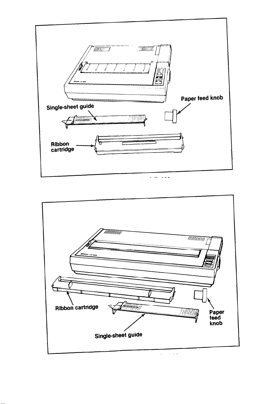
Figure 1-1. The LQ-800
Figure 1-2. The LQ-1000
1-2
Page 15
Remove the tape that holds the dust cover in place during shipping
and take the cover off the printer. Simply tilt the dust cover up and lift
it off the printer.
WARNING
The print head is protected by two plastic bumpers during shipping.
Both of these bumpers
must
be removed before turning on the printer.
Remove the long bumper to the right of the print head first, then move
the print head to the center of the LQ and remove the small bumper
on the left side of the print head.
There is a clear plastic overlay on the control panel to protect it
from scratching and discoloration. It’s up to you whether you remove
the overlay or leave it on.
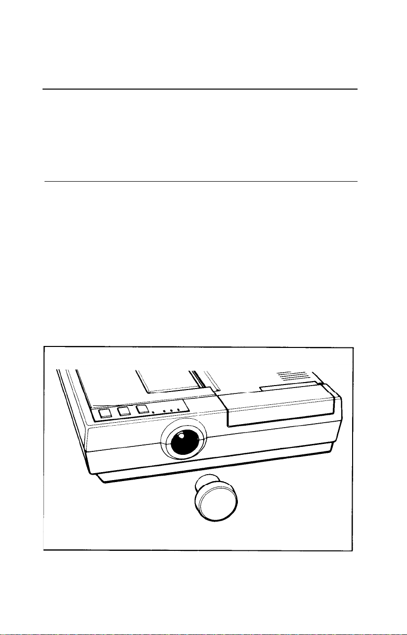
Installing the paper feed knob
Next install the paper feed knob. To install the knob, simply push it
onto the shaft on the right side of the printer, as shown in Figure 1-3.
The shaft has one flat side that must be matched with the flat side of
the hole in the knob.
Figure 1-3. Installing the paper feed knob
1-3
Page 16

Now that you’ve installed the paper feed knob, use it to remove the
sheet of paper wrapped around the printer’s platen (the black roller).
Selecting the Right Location
2
The most important consideration in choosing a location for
your printer is that it be close enough to connect a cable to your computer. But also keep the following tips in mind:
l
Place the printer or printer stand on a solid and level foundation.
Avoid setting it on carpet, chairs, or unstable surfaces.
l
Use a grounded outlet-one that has three holes to match the power
plug on the printer. Don’t use an adapter plug.
l
Avoid using electrical outlets that are controlled by wall switches-
if you accidentally turn off a switch, you could wipe out valuable
information and stop your printing.
l
Keep your printer and computer away from base units for cordless
telephones.
l
Avoid using an outlet on the same circuit breaker with large electri-
cal machines or appliances that might disrupt the flow of power to
your printer.
l
Protect your printer from direct sunlight, and keep it away from
excessive heat, moisture, and dust. Make sure it’s not too close to a
heater or any other heat source.
1-4
Page 17
Installing the Ribbon
3
printer for ribbon installation and paper loading. The next time you
install a ribbon or load paper, you can leave the cover on.
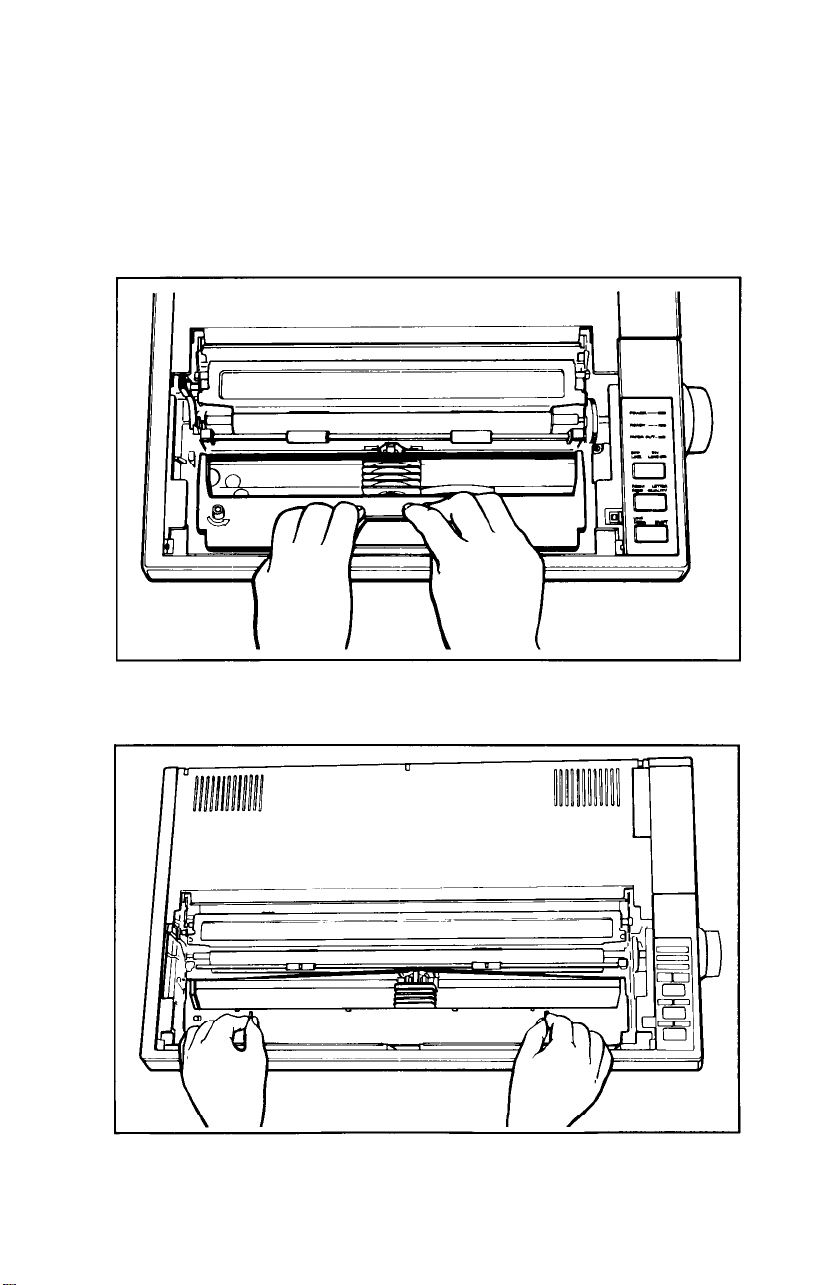
1. Manually move the print head to the middle of the platen.
2.
With the dust cover removed, you have easy access to the
Now you’re ready to install the ribbon.
WARNING
The power must be OFF when moving the print head. Moving
the print head when the power is ON may damage your
printer. If you’ve been using your printer just before changing
the ribbon cartridge, be careful not to touch the print head
because it becomes hot during use.
Before loading the cartridge into the printer, turn the small knob on
top in the direction of the arrow to tighten the ribbon as shown in
Figure
1-4.
Figure 1-4. Tightening the ribbon
1-5
Page 18
3. For the LQ-800, hold the ribbon cartridge by the raised plastic fin
on top of the cartridge; for the LQ-1000 hold the cartridge by the
two plastic tabs. Lower the cartridge into the printer, guiding the
two square pins on each. end of the cartridge into the slots in
the printer frame, as shown in Figures 1-5 and 1-6. Press firmly on
each end of the cartridge to make sure the pins are firmly seated in
the slots.
1-6
Figure 1-5. Loading the LQ-800 ribbon cartridge
Figure 1-6. Loading the LQ-1000 ribbon cartridge
Page 19
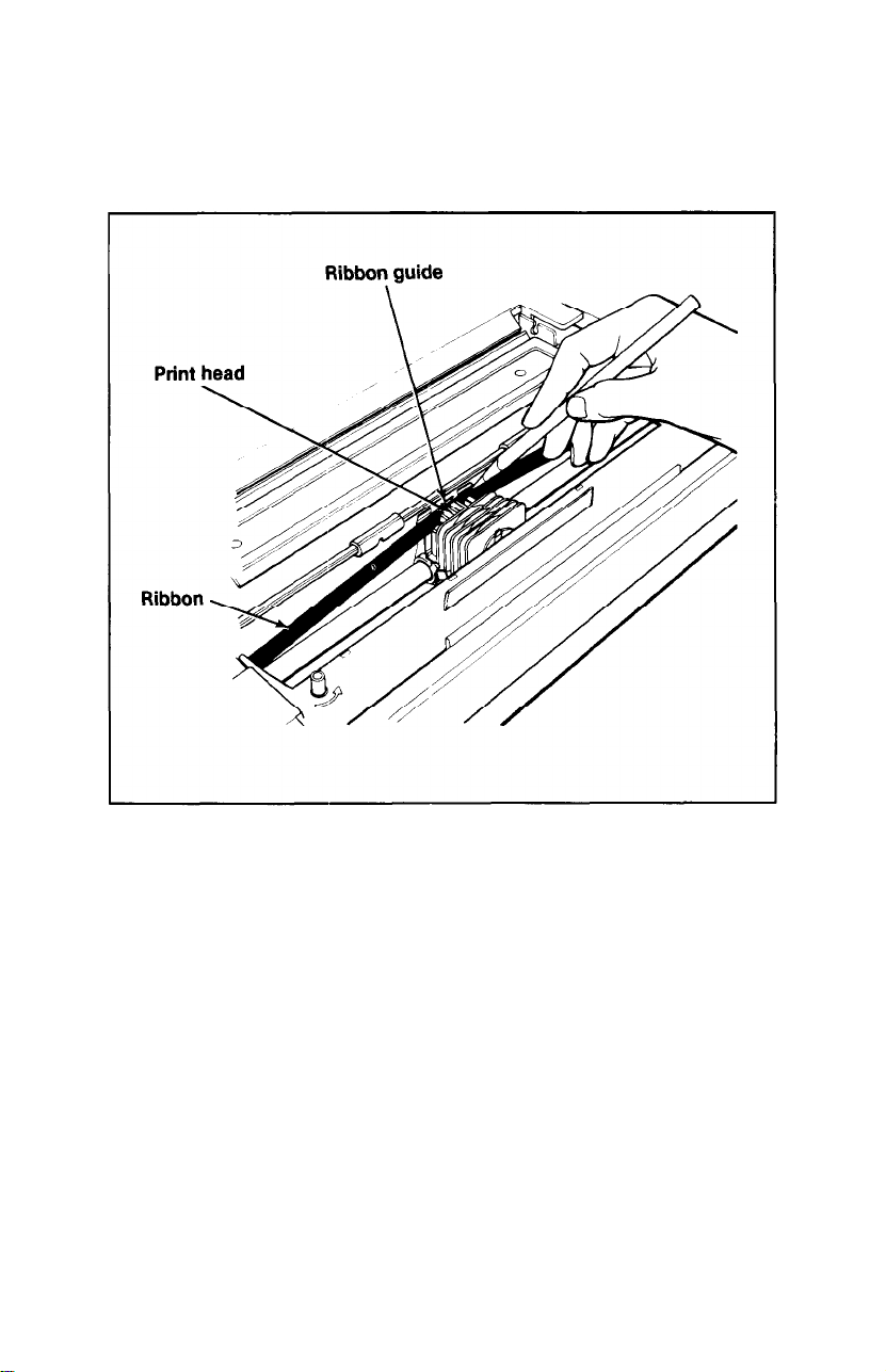
4. Now use the point of a pencil to guide the ribbon into place
between the ribbon guide and the print head as shown in Figure
1-7. (There is also a diagram on the top of the ribbon cartridge
itself.)
Figure 1-7. Positioning the ribbon
5. With the cartridge in place, again turn the ribbon knob in the direction of the arrow to tighten the ribbon.
And that’s it-the ribbon is now installed.
1-7
Page 20
Replacing the ribbon. . .
When buying new ribbon cartridges for the LQ-800 or 1000, be sure
you get a ribbon specifically for the LQ-800 or 1000. Ribbon cartridges
for other Epson printers, such as the FX series, may closely resemble
an LQ ribbon, but their use can damage the LQ print head. Also,
ribbon cartridges for the LQ-1500 will not fit the LQ-800 or 1000, and
the Epson ribbon replacement pack #8758 should not be used as a
replacement ribbon.
The LQ uses a continuous-loop, inked fabric ribbon. When your
printing becomes too light, replace the ribbon with a fresh cartridge.
To replace the ribbon, just pull up on the raised fin on top of the
LQ-800 cartridge, or the two plastic tabs on the LQ-1000 and lift the
cartridge out of the printer. To install a new ribbon, follow the preced-
ing steps.
Loading Single-Sheet Paper
4
of paper.
ing systems (the cut sheet feeder or the tractor unit), you should
complete the remaining setup steps before installing either of the
optional systems.
your computer (Step 9) before you install an optional system. After
completing the setup steps, see Chapter 2 for installing the cut sheet
feeder, or Chapter 3 for installing the tractor unit.
Installing the single-sheet guide
sheets of paper into the LQ.
spring, insert it into
When you receive your LQ, it is set up to print on single sheets
Even if you have purchased one of the optional paper feed-
first
It is much easier to run the self test (Step 8) and to connect the LQ to
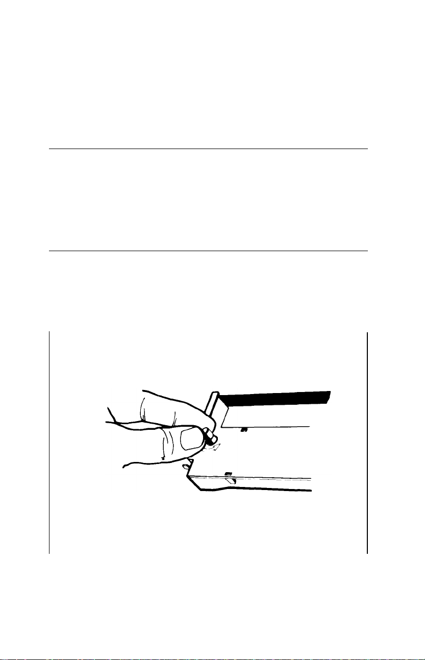
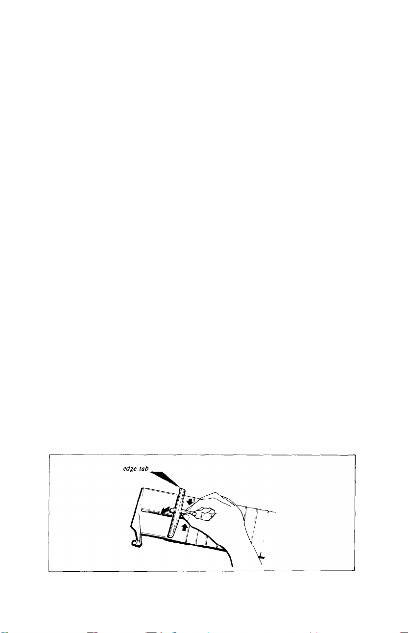
Now install the single-sheet guide. It helps you feed individual
First, put the edge tab into the guide frame. Holding the plastic
the groove as shown below.
1-8
Assembling the single-sheet guide
Page 21
The guide has rounded pins on each end. These pins fit into notches
on each end of the paper slot.
Slide one of the guide’s pins into one notch. Then, with gentle pres-
sure, snap the other pin into the other notch as shown in Figure 1-8.
Figure 1-8. Installing the single-sheet guide
The edge tab on the left side of the guide is movable, with a click
stop for its middle position. For standard-sized (8½-inch wide) paper,
see that the tab is in the click-stop position.
Loading the paper
Loading single-sheet paper in the LQ is simple-it’s just like loading
paper in a typewriter.
1-9
Page 22
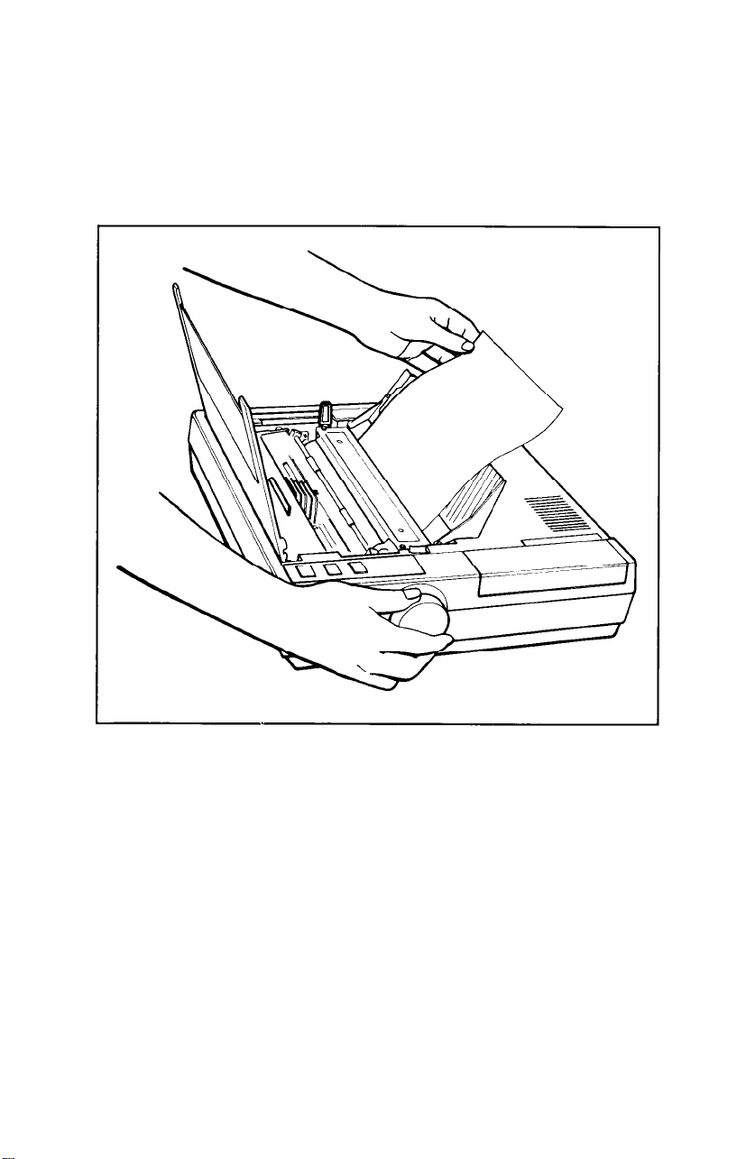
1.
Check that the dust cover is tilted up to make it easier to see inside
the printer, as shown in Figure 1-9.
2. Make sure the paper release lever is pushed back in the direction of
the arrow in the figure, and that the paper bail is pulled away from
the platen.
Figure 1-9. Loading single-sheet paper
3. Insert a single sheet of paper behind the platen as shown in Figure
1-9. Put the left edge of the paper against the edge tab on the single
sheet guide.
4. With the power OFF use the paper feed knob to roll the paper into
the printer far enough to be held by the paper bail. (If the power is
ON, use the LINE FEED button as described in Step 6.)
5.
Push the paper bail back against the paper, and the paper is ready.
1-10
Page 23

Caution
Never use the manual paper feed knob while the power is ON
because you can damage the paper feed motor. Always use
the
LINE FEED
the paper feed knob turns easily when the power is
difficult to turn while the power is
or
FORM FEED
button. You will also find that
OFF,
but is
ON.
When loading single-sheet paper, you may find that the LQ finishes
pages at different places than your word processor or applications
program does.
To ensure that your word processor and the LQ finish pages at the
same point:
1. Print out a page on the LQ. Check that the LQ and your word
processor have the same page length. If they differ, note how many
lines they differ by. For example, if your word processor is set up to
print 55 lines, but the LQ only prints 53 lines before ejecting the
page, there is a difference of two lines.
2. You now have three choices:
a) Compensate for the two-line difference when rolling the paper
into the printer.
b) Use the installation procedure on your word processor to
change the default page length.
c) Use commands in your word processing program to alter the
page or margin lengths in each file to accommodate the LQ’s
page length.
Once you’ve established the best settings, always load the paper so
3.
that your printer starts at the same place on each page. For example, you may find that when you roll the paper one inch above the
print head, the page finishes where you want it to-then each time
you load paper, load it the same way.
With single-sheet paper, the key to consistent page formatting is to
establish the settings that work best for you, then position the paper in
the
same place every time.
1-11
Page 24
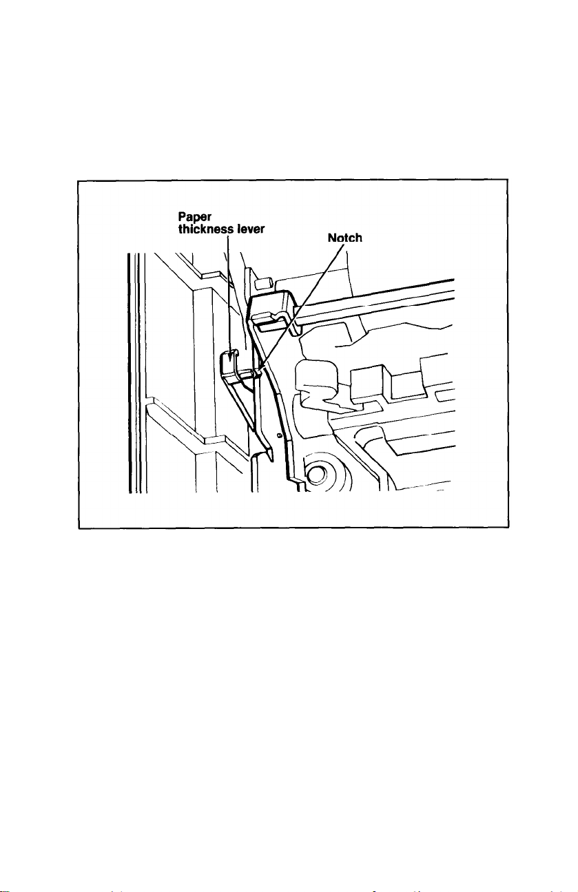
Adjusting the paper thickness lever
The LQ is equipped with a paper thickness lever that can be
adjusted to accommodate varying thicknesses of paper.
The lever is located in front of the paper release lever on the left side
of the printer as shown in Figure
1-10.
Figure 1-10. Paper thickness lever
When you receive your LQ, the lever is set for standard paper thickness (about
ness lever set in the notch shown in Figure
For thicker paper or multiple copies, pull the lever toward the front
of the printer. To return the lever to the standard position, push it back
until it clicks into the standard setting.
1/500th
of an inch), with the small arm on the paper thick-
1-10.
Turning On the Power
5
the printer on and become acquainted with the power-up sequence.
1-12
With the ribbon and paper installed in the LQ, it’s time to turn
Page 25
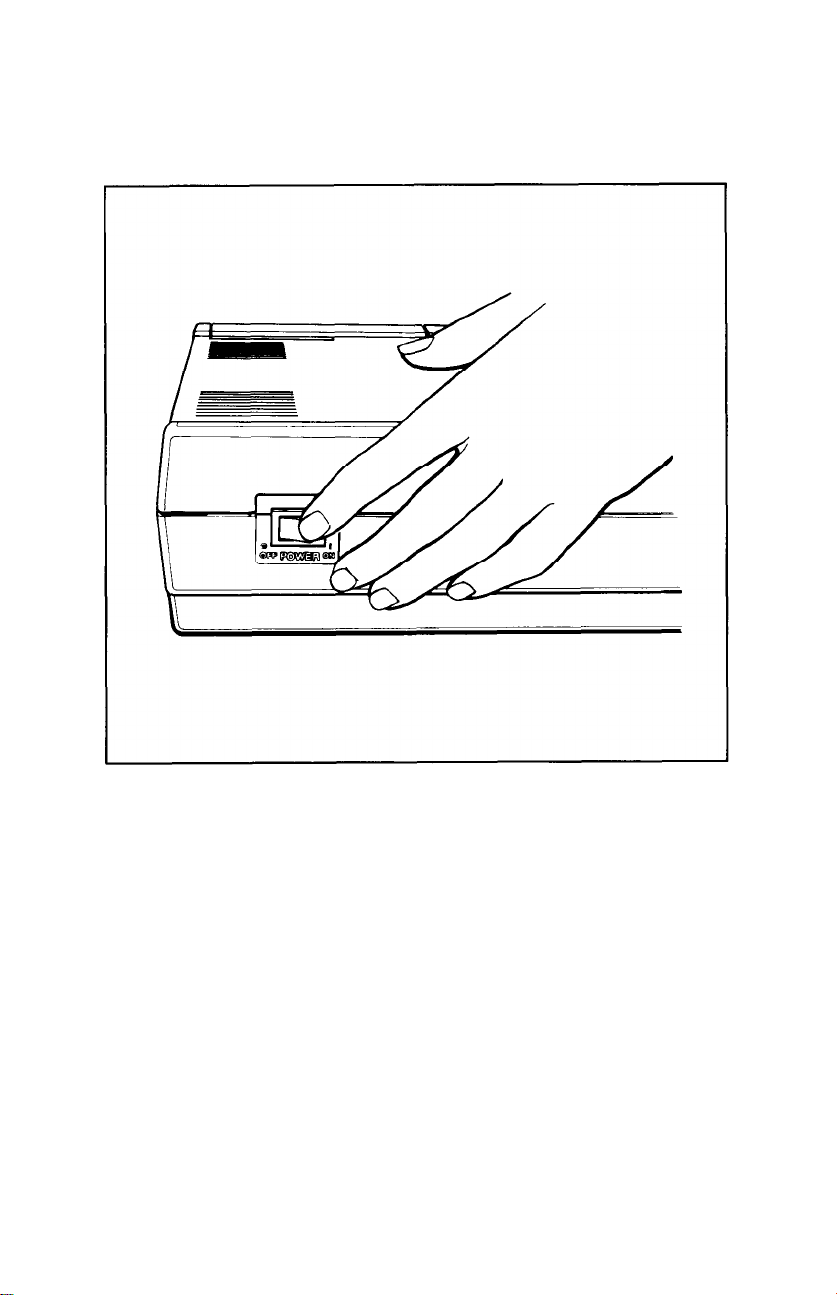
Plug in the printer’s power cord, making sure the outlet is properly
grounded. Turn the power ON with the switch on the left side of the
printer (see Figure
1-11).
Figure 1-11. Turning on the power switch
When the power is turned ON:
l
The print head moves back and forth and stops at the left side of the
printer.
l
The printer
printer is reset to its
is initialized-any
default
(or preset) values. See Appendix I for a
previous settings are erased, and the
list of default values.
l
The three green lights on the control panel--POWER, READY, and
ON LINE-go on. (The red PAPER OUT light does not go on unless
the
printer
is out of
paper.)
1-13
Page 26
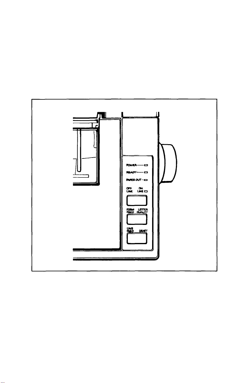
Operating the Control Panel
6
1-12) has two functions-the functions marked in blue (ON LINE,
LETTER QUALITY, and DRAFT) are active when the printer is on
line; the functions marked in black (OFF LINE, FORM FEED, and
LINE FEED) are active when the printer is off
line when the ON LINE light is on; it is off line when the ON LINE
light is off.
Each of the three buttons on the LQ control panel (see Figure
line.
The printer is on
Figure 1-12. The LQ control panel
OFF LINE/ON LINE
OFF LINE--If you press this button when the green light beside it is
on, the ON LINE and READY lights go off, the print head moves to
the center of the platen, and the printer is set
on but the LQ won’t print. This enables the form feed and line feed
functions to work.
1-14
off line-the
power is still
Page 27

ON LINE-The green ON LINE light indicates that the printer is on
line
and ready to receive data. When the LQ is on line, you can select
either the Letter Quality or draft mode.
FORM FEED/LETTER QUALITY
FORM
FEED-Pressing this button advances the paper to the top of
the next page if you’re using continuous-feed paper (see Chapter 3,
“Installing the Tractor Unit”). If you’re using single-sheet paper, it fully
ejects one sheet. The form feed function works only when the printer
is off line.
LETTER QUALITY-Pressing this button selects the Letter Quality
typestyle (for more information on Letter Quality, see Step 7). The
printer beeps twice to acknowledge the Letter Quality selection. You
can select the Letter Quality typestyle with this button only when the
printer is on line.
LINE FEED/DRAFT
LINE FEED-Pressing this button advances the paper one line at a
time, either while you’re loading paper, or when you’re adjusting
where you want printing to begin. If you hold this button down, the
paper advances continuously. The line feed function works only when
the printer is off line.
DRAFT-Pressing this button selects the draft typestyle. The printer
beeps once to acknowledge the draft selection. The draft function
works only when the printer is on line.
Note
Use the LETTER QUALITY or DRAFT buttons before you
tell the computer to print. Do not use them while the LQ is
printing.
1-15
Page 28

Selecting the Letter Quality or Draft Mode
7
Quality mode. As shown in the sample below, the Letter Quality
characters are fully formed and are ideal for formal correspondence or
other presentation-quality work.
draft mode, also shown below. In draft mode, the LQ prints more
quickly, because fewer dots are used to form each letter.
draft mode.
l Control panel-You can choose between the Letter Quality and
l
l
When you receive your LQ, it is preset to print in the Letter
For
those
times when you need only a rough draft, the LQ also
This is the Letter Quality style
This is the draft Style
The LQ gives you three ways to select either the Letter Quality or
draft modes with the appropriate button
DIP switch-A switch on the back of the printer selects either Letter
Quality or draft as the
turn the power
Software command-You
ity and draft modes by sending a command to the printer as
explained in Chapter 5.
default
on).
See Appendix A for details.
typestyle (the style in effect when you
can
also switch between the Letter Qual-
on
the control panel.
has a
These three choices allow you to tailor the LQ to your printing
needs. If you find you use the Letter Quality mode most of the time,
you can leave the settings just as they are. If you print in draft mode
more than Letter Quality, just reset the DIP switch as outlined in
Appendix A. But no matter what you choose, you can always use the
buttons on the control panel to switch between the two styles.
Running the Self Test
8
prints out all of the characters in the selected character set-either
Letter Quality or draft.
printer and that the power is turned OFF. If you have an LQ-1000, be
sure to use 14-inch-wide paper to avoid printing on the platen.
1-16
The LQ has a built-in self test function that automatically
Before running the self test, make sure that paper is loaded in the
Page 29
To run the self test in the Letter Quality mode, hold down the
LETTER QUALITY button while you turn the power switch ON. To
run the test in the draft mode, hold down the DRAFT button while
turning the power ON. The self test then takes over.
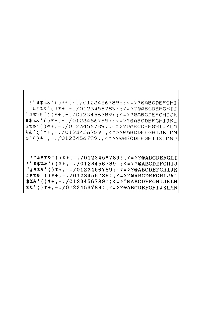
The self test prints a version identification number, the name of the
installed typeface family, then (as you can see in Figure 1-13) all of the
characters in the selected character set.
The self test continues until you turn the printer off or until it runs
out of paper.
Draft
Letter Quality
Figure 1-13. LQ self test in draft and Letter Quality modes
Connecting Your Printer to Your Computer
9
Your LQ printer comes equipped with separate connections
for
both
serial and parallel interfaces, so be sure to use the type your
computer requires. Check your computer’s documentation if you’re
unsure which interface you have. (If your computer requires a
different type of interface, see your Epson dealer.)
1-17
Page 30
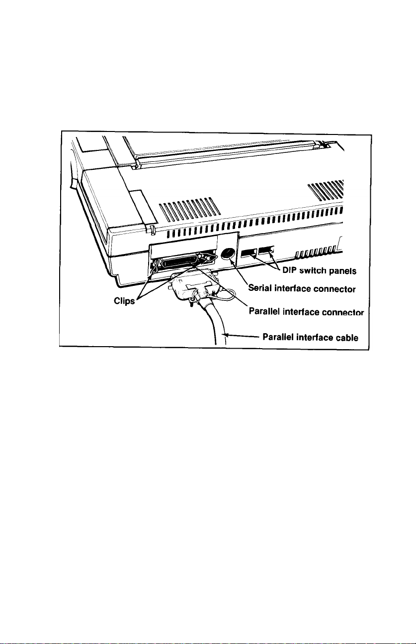
The parallel interface
The connector on a parallel interface cable, as shown in Figure 1-14,
is secured to both the LQ and your computer by two clips. After plugging the cable into the LQ and your computer, be sure to snap the clips
in place, and connect the ground strap if the cable is equipped with
one.
Figure 1-14. Connecting a parallel interface cable
Once you’ve connected a parallel cable, you’re ready to print. The
parallel interface does not require any additional settings.
The serial interface
If your computer is equipped with a serial interface, you should use
an Epson serial interface cable-#8239 for the Apple® IIc, #8293 for
the Apple IIe
or
Epson QX™-16, and #8294 for the IBM® PC. Plug the
cable into the connector to the right of the parallel connector.
When using the serial interface, you need to reset four DIP switches
so that your computer and printer will communicate properly. See
Appendix A for a complete explanation of the DIP switches and how
to set them for your serial interface.
1-18
Page 31

Printing Your First Document
10
ing steps, your LQ is ready to print. The following chapter explains
how to set up your word processor to work with the LQ.
Additional chapters and appendixes cover programming, control
codes and ESCape sequences, technical specifications and maintenance .
If you have any difficulty printing your first document, check the
following list to make sure you’ve completed all the setup steps.
q
Did you remove the plastic tab that holds the print head in place?
q
Is the power source (power strip, etc.) turned ON?
q
Is the ribbon properly installed? Make sure the ribbon is in front of
the print head, not riding above it.
q
Have you loaded the paper correctly? (Read Chapter 2 or 3 if you
are using the optional cut sheet feeder or tractor unit.)
q
Are the green POWER, ON LINE, and READY lights on the con-
trol panel ON? If not, press the ON LINE button to place the LQ
on line. If the red PAPER OUT light is ON, check that you’ve
loaded the paper correctly.
Now that you’ve completed the basic setup and operat-
q
Were you able to successfully run the self test in Step 8? If not,
check the DIP switch settings and try again.
q Is your printer properly connected to your computer? Are you
using the correct interface (serial or parallel)? If you’re using a
serial interface, have you set the DIP switches accordingly?
If you’re still having trouble printing, read the troubleshooting sec-
tion in Appendix D.
1-19
Page 32

Chapter 2
The Cut Sheet Feeder
The cut sheet feeder automatically loads single sheets of paper into
the LQ, allowing you to print on letterhead, bond, or individual
forms.
Installing the Cut Sheet Feeder
1. Make sure the power is OFF.
2.
Set DIP switch 1-8 on the back of the printer to the ON position
and DIP switch 1-7 to the OFF position to select the cut sheet
feeder. See Appendix A for information on resetting the DIP
switches.
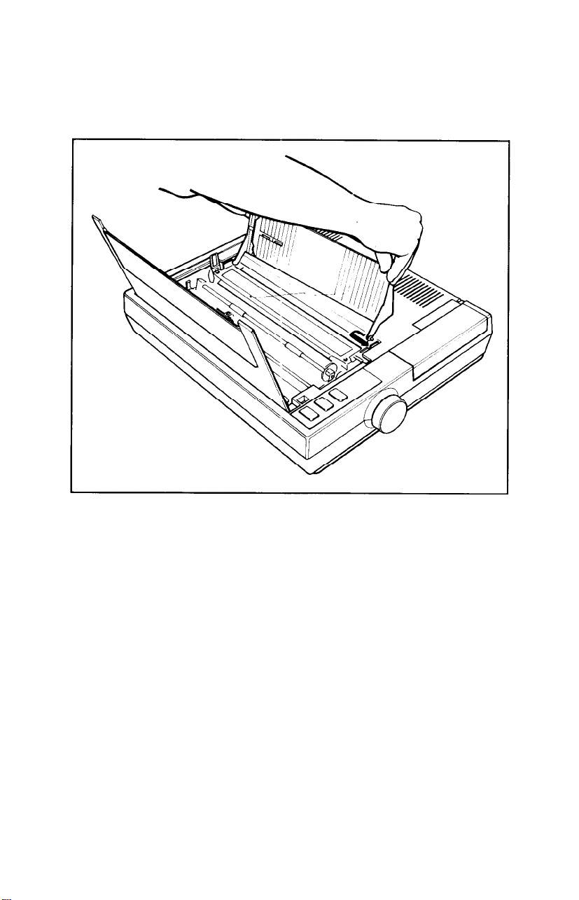
3. Remove the front cover that came installed on your LQ by tilting it
up and lifting it off the printer. Replace it with the new cover
included with the cut sheet feeder, as shown in Figure
new cover in an upright position so you can see inside the printer.
Also remove the single-sheet guide.
2-1.
Leave the
Figure 2-1. Preparing the printer for installation
2-1
Page 33

4. Make sure the paper release lever is pushed back as shown in Figure
2-1.
If this lever is not pushed back, the cut sheet feeder will not
fit or operate properly.
5. Pull the paper bail away from the platen (the black roller) as shown
in Figure 2-1. The paper bail should remain in this position whenever the cut sheet feeder is installed.
6. Now locate the rear mounting pins on the LQ as shown in Figure
2-2. The rear notches on the cut sheet feeder unit rest on these
mounting pins.
2-2
Figure 2-2. Installing the cut sheet feeder
Page 34

7.
Hold the cut sheet feeder assembly in two hands, and press the two
cut sheet feeder release levers shown in Figure 2-1.
8. Now stand directly over the printer, look
through
the top of the cut
sheet feeder, and guide the rear notches on the cut sheet feeder onto
the rear mounting pins on the printer.
9. Tilt the cut sheet feeder forward until the front latches of the cut
sheet feeder engage the front mounting pins on the printer. Release
the levers and the cut sheet feeder locks in place.
Note
When the cut sheet feeder is properly installed, it
is
possible to
tilt it forward slightly, but you cannot remove it from the
printer without pressing the release levers. If you can remove
the cut sheet feeder by simply lifting it off the LQ, reread the
installation instructions, paying special attention to setting
the rear notches of the feeder on the rear mounting pins of the
printer.
10. With the cut sheet feeder in place, you can now install the three
brackets supplied with the unit. To install the two small brackets,
squeeze them together and insert them into the holes on top of the
paper supports, as shown in Figure 2-3.
Figure 2-3. Installing the small brackets
2-3
Page 35

11.
For the LQ-800 model, install the large bracket in the stacker as
shown in Figure 2-4. Slip the legs of the bracket into the metal
slots on the bottom of the cut sheet feeder and make sure the
bracket fits into the retaining clips on the upper part of the
stacker.
Figure 2-4. Installing the large bracket
For the LQ-1000 model, there are two large brackets. Install them
both as described above and also install the paper stand shown in
Figure
2-4
2-5.
Page 36

Figure 2-5. The LQ-1000 model
Preparing the Paper for Loading
1.
The paper
curled or uneven, it will not feed correctly.
2. The cut sheet feeder holds a maximum of 60 sheets of standard
weight (20 lb.) paper. If you use a lighter or heavier weight of
paper, compensate accordingly. (If more than one sheet of paper is
being loaded at a time, remove some of the paper from the paper
bin.)
3. Loosen the paper stack by rifling through it a couple of times, then
tap it on a flat surface to make it even.
must
be straight and clean. If the paper is slightly bent,
2-5
Page 37

Loading Paper
1. Align the arrow on the left paper guide with the arrow stamped
into the metal lip of the stacker, as shown in Figure
Figure 2-6. Paper support and paper loading lever
2-6.
2.
Pull the paper loading lever forward until it locks in the open position, as shown in Figure
2-6
2-6.
Page 38

3.
Set the stack of paper in the paper bin, aligning it against the left
paper guide as shown in Figure
2-7.
Move the right paper guide
over to the edge of the stack of paper, but leave a little room so the
paper doesn’t bind. Make sure the paper is
behind
the angled metal
tabs at the bottom of the left and right paper guides.
Figure 2-7. Loading paper; adjusting the right paper guide
4.
Push the paper loading lever back, and the stack of paper is pushed
forward against the two feeder rollers.
2-7
Page 39

setting up your word processor for a cut sheet feeder. . .
If you‘ve never used a cut sheet feeder before, you may have to set
up your word processor accordingly.
When the cut sheet feeder positions the paper for printing, it automatically leaves a one-inch margin at the top of a page. If you’ve been
printing with continuous-feed paper, you11 need to adjust the settings
on your word processor so that the pages print the same with the cut
sheet feeder.
There are three settings you’ll probably need to change: Page
Length, Top Margin, and bottom Margin. Most word processors
have preset (or default) settings that are in effect each time you use the
program. Check the program’s documentation to find these settings,
and how to change them.
The following is an example of a typical conversion.
To maintain 55 printed lines per page:
Continuous-feed
settings
Change Page Length
Change Top Margin
Change Bottom Margin
Many word processors give you two choices in changing these settings: 1) You can change the settings in each individual file you print,
or; 2) You can change the program’s default settings so that every time
you use the program, these new settings are in effect.
If your program has additional features, such as headers and foot-
notes, you will have to compensate accordingly. (For example, many
programs include the header as part of the top margin. If you set the
top margin to 0, you11 lose the header.)
With a little bit of experimenting, you’ll find the best equivalent
settings to use.
from
from
from
66
3 (default) to 0
8 (default) to 6
Cut sheet
feeder settings
to 61
2-8
Page 40

Printing with the Cut Sheet Feeder
1. Turn the power ON with the switch on the left side of the printer, as
shown in Figure
2-8.
Figure 2-8. Turning the power on
2. When you turn the power ON:
l
The print head moves to the left side.
l
The POWER, READY, and ON LINE lights glow green.
l The red PAPER OUT light goes on. (The PAPER OUT light
remains on until paper is fed into the printer.)
3. Now print a document with your word processor as you normally
would. When you print a document:
l The print head moves to the center of the platen to facilitate
paper loading.
l
The feeder rollers feed one sheet of paper into the printer, and
position the page with a one-inch margin at the top. (See the
previous note “Setting up your word processor for a cut sheet
feeder. . ."
for information on adjusting margin and page length
settings.)
2-9
Page 41

l The red PAPER OUT light goes out while there’s paper in the
printer.
l
Printing begins.
When the LQ finishes printing a document, you have three options.
If you wish
to
continue printing-You can print another document as
you normally would; the cut sheet feeder ejects the last page from the
previous job, then loads and prints the new document.
If you want to fully eject the last page of a document-First take the
LQ off line by pressing the ON LINE button (the green ON LINE light
goes out). Press the FORM FEED button to eject the last page into the
paper stacker, and a new sheet is automatically loaded.
If you’re finished printing-Remove the unused paper from the bin,
take the printer off line, then use the FORM FEED button to eject the
last sheet of paper. (If you press FORM FEED without removing the
remaining paper from the bin, another sheet is loaded.) You can also
shut the power OFF, then use the manual paper feed knob to roll the
remaining sheet out of the printer.
Caution
When the power is ON, you should use only the FORM FEED
or LINE FEED button to eject paper from the cut sheet feeder.
If you use the manual paper feed knob, the power should
always be OFF to prevent damage to the paper feed motor.
Removing the Cut Sheet Feeder
To remove the cut sheet feeder:
1. Turn the power for the printer OFF.
2. Remove all the unused paper from the bin, and any printed sheets
from the stacker.
3. If a sheet of paper is still loaded in the printer, use the manual paper
feed knob to remove it.
2-10
Page 42

4. Hold the cut sheet feeder on each side, press the release levers as
shown in Figure 2-9, and lift the unit off the printer.
Figure 2-9. Removing the cut sheet feeder
Remember, if you decide to print with another type of paper feed
system, such as the optional tractor feed, you’ll
l
Reset DIP switch 1-8 from ON back to OFF. (Don’t forget to turn
have to:
the power OFF then ON again so the printer will record the new
setting.) Reset DIP switch 1-7 (skip-over perforation) if you’re using
continuous-feed paper.
l
Check any settings you might have changed in your word processor
to compensate for the cut sheet feeder.
l
Replace the original front cover if you’re loading individual sheets
of paper (you can leave the narrow front cover on if you’re using
the optional tractor feed unit).
2-11
Page 43

Troubleshooting
If you have any difficulties operating the cut sheet feeder, check the
troubleshooting list shown below. If you continue to have difficulty,
consult your authorized Epson dealer.
Problem
Cut sheet feeder does not fit flush
on the printer.
Printer doesn’t print; cut sheet
feeder doesn’t operate.
Cut sheet feeder operates but
doesn’t load paper.
Paper loads unevenly from the
paper bin.
Recommendation
Check that the paper release lever
on the left side of the printer is
pushed back, and that the paper
bail is pulled away from the platen.
Review the installation instructions.
Make sure the cable is properly
connected to the printer and computer.
Check that DIP switch 1-8 is ON
and 1-7 is OFF, and that the printer
has been switched OFF, then ON
again to recognize the settings.
Review the paper loading instructions-you must open the paper
loading lever first, then set the
paper on the paper shelf. If you set
the paper on the gray rollers then
open the paper loading lever, the
paper drops down too far, becomes
uneven, and does not load properly.
If too much paper is loaded, it spills
off the paper shelf.
Paper jams when it feeds through
the cut sheet feeder.
2-12
Check to see that the paper is
stacked evenly
Check to see if there is too much
space between the paper stack and
the right paper guide, causing
paper movement and unevenness.
Page 44

Problem
Recommendation
Two or more sheets of paper are
loaded instead of one.
Printing starts too low on the page.
Printing is too close or too far from
the left side of the paper.
Paper doesn’t eject evenly.
Remove paper and fan it. Paper
was not sufficiently loosened
before being loaded into the paper
bin.
Make sure paper is loaded behind
the metal tabs on the bottom of the
left and right paper guides,
Too much paper was loaded into
the paper bin-remove some of the
unused sheets.
The weight of the paper is too light.
Add paper.
Your word processor may not be
set up properly. Review “Setting up
your word processor for a cut sheet
feeder . . .”
Make sure the arrow on the left
paper guide is aligned with the
arrow stamped on the lip of the
stacker.
Check that there’s enough room in
the stacker. If not, remove some of
the printed sheets.
More than one sheet of paper may
have been loaded, which causes
the paper to eject unevenly Make
sure that paper was separated and
loaded properly
Maintenance
To keep your cut sheet feeder working smoothly, keep it away from
dust, grease, and any heat sources. A safe temperature range is 41° to
95°F.
Use a soft, clean cloth dampened with water to clean the outside of
the cut sheet feeder case. Stubborn stains can be removed with nonabrasive household cleaners.
2-13
Page 45

Periodically, the inside of the cut sheet feeder should be cleaned to
get rid of dust and paper lint. First, turn the power OFF and remove
the cut sheet feeder from the printer. Then use a soft brush to clean the
inside areas. Make sure the gray rollers are kept free of dust so that the
paper feeds evenly.
If you have any problems, contact your authorized Epson dealer.
2-14
Page 46

Chapter 3
The Tractor Unit
The tractor unit for the LQ is easy to install and use. Before you
begin the installation, make sure you have received the following:
l
The tractor unit
l
The smoke-colored tractor cover
l
The narrow front lid
l
The paper separator
l
The paper shelf
Setting Up the LQ for Continuous-feed Paper
Before installing the tractor unit, you should set up your LQ so that
continuous-feed paper can flow freely in and out of the printer.
Use any arrangement that allows you to put the paper underneath or
behind the printer. There are many types of printer stands you can use;
one example is shown in Figure 3-1. If you prefer, you can stack the paper
behind the printer as shown in Figure 3-2.
Figure 3-1. Continuous-feed paper with printer stand
3-1
Page 47

Figure 3-2. Continuous-feed paper without stand
Installing the Tractor Unit
1.
Remove the original dust cover that was included with your LQ.
Replace it with the front lid packaged with the tractor unit, and
leave it tilted up, as shown in Figure
3-3.
Figure 3-3. Installing the tractor unit
2. Hold the tractor with the gears to the right, and fit the rear notches
on the tractor unit over the rear mounting pins on the printer, as
shown in Figure
3-2
3-3.
Page 48

3. Tilt the tractor unit toward you until the front latches click in place
over the front mounting pins on the printer.
Loading Paper
To load continuous-feed paper, follow these instructions:
1. Make sure that the printer is turned OFF.
2. Move the print head to the center of the printer, pull the paper bail
away from the platen, and pull the paper release lever forward, as
shown in Figure 3-4.
Figure 3-4. Preparing for paper loading
3-3
Page 49

3. Using Figure
3-5
as a guide, pull the locking levers on the pin-feed
holders forward so that you can move the holders to the left and
right.
Figure 3-5. Moving the pin-feed holders
4. Position the left holder all the way to the left and push the locking
lever back to lock that holder in place. Leave the right holder
unlocked.
5.
Open the pin-feed covers as shown in Figure
3-4
3-6.
Page 50

Figure 3-6. Opening the pin-feed covers
Now install the paper shelf by fitting it into the two notches on the
6.
back of the printer, as shown in Figure 3-7. The paper shelf keeps
the paper from getting caught on the interface cable.
Figure 3-7. Installing the paper shelf
3-5
Page 51

If you have an LQ-800, center the one support in the middle of the
7.
tractor as shown in Figure
3-7.
If you have an LQ-1000, space the
two paper supports evenly along the width of the paper.
Now guide the paper behind the platen, and push it through until it
8.
comes up between the ribbon guide and the platen as shown in
Figure 3-8. (Moving the paper with a side-to-side motion makes it
easier to push the paper through.)
3-6
Figure 3-8. Loading paper
Page 52

9. Pull the paper up until the top is above the pin-feed holders. Fit
the holes on the left side of the paper over the pins in the left
holder (as shown in Figure 3-9) and close the cover.
Figure 3-9. Fitting the paper over the pin feeds
10. Fit the right side of the paper into the right holder, moving the
holder as needed to match the width of the paper.
11. Close the right cover, making sure the paper has no dips or
wrinkles and lock the right holder in place.
Push the paper bail against the paper and that’s it . . . the paper is
12.
ready.
3-7
Page 53

Figure 3-10. Top-of-page position
Setting the top-of-page position . . .
Once you‘ve loaded continuous-feed paper into your LQ, you need
to establish a top-of-page position so that the printed pages end where
you want them to and do not cross over a perforation between pages.
To set the top-of-page position, make sure the power is OFF and
use the paper feed knob to advance the paper until a perforation
between sheets lines up evenly with the top of the ribbon guide, as
shown in Figure 3-10.
Now turn the printer ON. This records the top-of-page setting.
The printer remembers this setting and uses it when any program tells
it to move to the top of the next page, or when you use the FORM
FEED button to advance the paper.
If you are using a word processor or other applications program
and the printing is too high or too low on the page, adjust your top-ofpage setting accordingly,
Installing the paper separator and tractor cover
Once you’ve loaded paper into the LQ and are familiar with the
steps, you can attach the paper separator that comes packaged in the
cardboard enclosure. The separator ensures that the paper coming out
of the printer is not pulled back in.
3-8
Page 54

The separator has rounded pins on each end that fit into notches
located just behind the tractor unit. Slide one of the separator’s pins
into one notch, then with a gentle pressure, snap the other pin into the
other notch as shown in Figure 3-11.
Figure 3-11. Installing the paper separator
3-9
Page 55

The smoked plastic tractor cover is the finishing touch. Simply
place it over the tractor unit, making sure the notches on the side of
the cover fit into the slots on the printer, as shown in Figure
3-12.
3-10
Figure 3-12. Installing the tractor cover
Page 56

Removing the Optional Tractor Unit
When you want to remove the optional tractor unit from the LQ
simply push back on the tractor release levers as shown in Figure 3-13,
tilt the unit back, and lift it off the printer.
Figure 3-13. Removing the optional tractor unit
3-11
Page 57

Chapter
4
Using the LQ with Commercial Software
Now that you have set up and tested your printer, you can do any
of these things:
l
Use the printer with commercial software (such as a word proces-
sor, spreadsheet, or database).
l
Learn about the features of the printer.
l
Write programs to use the features of the printer.
Most of you probably want to begin using your LQ with commercial software to print such items as documents, reports, letters,
spreadsheets, and graphics. This chapter tells you what you need to
know.
If you want to learn more about the features of the LQ, also read
Chapters 5 and 6. For programmers the important parts of the manual
are the command summary and the other appendixes.
Using Commercial Software
Commercial software programs usually need to know what type of
printer you are using. You normally supply this information as part of
a setup or installation process. Either the manual for your program or
an on-screen menu should explain this process for you.
The program may list a number of printers from which you can
choose. Pick LQ-800 or LQ-1000, depending on which printer you
have.
4-1
Page 58

If neither one of these printers is listed, choose
LQ-1500
because
that printer recognizes virtually the same codes that the LQ-800 and
LQ-1000 use. (If you have a program that does not list the LQ-1500 as
an option, you may be able to obtain an update from the manufacturer. Contact your software dealer or the manufacturer to see if an
update that includes the LQ-1500, LQ-1000, or LQ-800 is available.)
If your program does not list any LQ printers, choose a printer from
the list below. They are listed in order of preference.
FX
LX
Rx
MX
Epson printer
Draft printer
Once you have set up or installed your commercial software pro-
gram for your printer, simply follow the program’s printing instruc-
tions. If you have any trouble
when
you print, turn to the first section
in Appendix D for help.
4-2
Page 59

Chapter 5
LQ Features
This chapter describes many of the printing features of the LQ. You
can read this chapter if you wish, but you may not need to. Whether
or not you use the rest of this manual depends upon your expertise,
your interest, and the software you use.
The demonstration programs in this chapter enable you to see LQ
features and print styles in action. Below are a few of the many fea-
tures covered:
Letter Quality
High
Emphasized
Double-strike
Italics
Elite
Fifteen Characters Per Inch
Underlined
Double-width
Condensed
Superscript
Proportional
Speed Draft
Subscript
ESCape and ASCII
The details of printer-computer communication are complex, but
for most purposes all you need to know is that the computer sends a
series of codes (each consisting of one or more numbers) to the printer,
and the printer interprets them.
5-1
Page 60

Some codes tell the printer to print a character, and other codes tell
it to turn on or off certain printer functions, such as emphasized or
Letter Quality. Because the codes between 0 and 127 are basically
standardized by the American Standard Code for Information Interchange (ASCII), they are referred to as ASCII numbers in this manual.
Nearly all of the codes for printer functions require more than one
number and begin with a special code, called the escape
code.
This
code signals that the next number is a code for a printer function and
its name is usually printed with the first three letters capitalized
(Escape) or it is abbreviated ESC or (ESC) .
In the demonstration programs in this manual, you’ll see how
ASCII and ESCape codes are used in the BASIC programming language.
l
LPRINT signals that information is to be sent to the printer.
l
The CHR$ (character string) function is used for numerical codes.
l
CHR$(27) is the ESCape code.
l
Quotation marks are used for printable characters, such as letters of
the alphabet.
Your word processing or business program may use other methods
to send those codes, such as pressing the ESC key for the ESCape
code. See your software manual for further information and use
Appendix B of this manual to find the proper codes. Appendix D also
has some suggestions on using LQ features with applications soft-
ware.
Demonstration Programs
To enable you to see the LQ features in action, this manual includes
demonstrations in the BASIC programming language. Although you
will probably not do much of your printing using BASIC, the demon-
strations are in BASIC because nearly all personal computer systems
include some version of this language. Therefore, almost everyone
can try the examples.
As you run the programs (or even as you read the explanations and
look at the printed examples), you learn how the LQ responds to the
messages your computer sends it by printing letters, numbers, symbols, and graphics in various print modes.
5-2
Page 61

Even if you never use BASIC again, you will know the capabilities
of your printer, capabilities that can often solve your printing problems. For example, if you need a special symbol, such as a Greek letter, you will
know that
you can turn to the chapter on user-defined
characters and create such a character.
If you don’t want to do
In most cases the software
or graphics does
the
the
exercises in BASIC, you don’t have to.
that
you use for word processing, business,
calculating and communicating with the printer
for you. All you need to do is install your software as explained in
Chapter 4.
Running BASIC programs. . .
This section describes how to run the BASIC demonstration pro-
grams in this manual; it is not a tutorial in BASIC programming.
Although there are many versions of BASIC, the programs in this
manual are designed to work with the two most popular ones: Microsoft™ BASIC and IBM PC BASIC. If you have another version, you
can run these demonstration programs by making a few changes.
Appendix D has instructions for using Applesoft™ BASIC; for other
versions of BASIC, consult the appropriate manual.
When you type these programs, be sure to include all spaces and
punctuation marks, especially semicolons. Press
of each line. (On your computer the
or ENTER.) Computers that use a 40-column display may break
some lines into two parts on the screen, but that does not affect the
operation of the program. If you make a typing mistake, retype
whole line, including the line number; the new line will replace the old
one.
RETURN
RETURN
key may be marked
at the end
the
When you
to run the program.
If you have made changes to a program and want to see all of it on
the screen, type
your screen. When you are completely through with one program
and want to start another, type NEW and press RETURN.
have
typed all
LIST and then press
the lines,
type
RUN and press
RETURN
to see the program on
RETURN
5-3
Page 62

Sending Control Codes to the Printer
The short program that follows illustrates the concepts of control
codes and ESCape sequences. This exercise may help you make better
use of this chapter and the next. Type and run the program. It should
produce the printout you see below it. After the printout you’ll find a
detailed description of the operation of the program.
10 LPRINT "BASIC programs for the"
20 LPRINT CHR$(76)CHR$(81)CHR$(45);
25 LPRINT CHR$(56)CHR$(48)CHR$(48);
30
LPRINT
40
LPRINT "W1 "CHR$(87)CHR$(49)
50 LPRINT CHR$(27)"W1";"Double-width print"
60 LPRINT "Still double-width"
Basic programs for the
LQ-800 and LQ-1000
W1 W1
Double-width
Still
" and LQ-1000"
print
double-width
In each line LPRINT signals that the rest of the information on the
line is to be sent to the printer. In lines 10 and 30 the letters inside the
quotation marks are printed just as they appear in the program.
Lines 20-25 show an alternate way of printing characters. They
use the CHR$ (character string) function with the decimal code for
each letter to print “LQ-800.”
Line 40 prints the characters W1 using the two different methods
(quotation marks and the character string function). Line 50 shows
that if the ESCape code, which is CHR$(27) in BASIC, comes before
the characters W1, those characters are not printed. Instead, they
become part of the ESCape sequence that turns on double-width
printing, which is demonstrated with the letters in quotation marks
after the ESCape sequence. Line 60 shows that the double-width mode
stays on for more than one line.
This program is only an introduction. The demonstration pro-
grams that follow allow you to see many more of the features of your
LQ in action.
5-4
Page 63

Basic Widths
The first programs print characters in the LQ’s three basic widths.
Further programs show you how to produce other character widths
by condensing and widening the basic ones.
Pica printing
The first program prints a sample line of characters in pica. This is
the
default
receives a command to use one of the other two basic widths.
Now run the program to print the results you see below-10 characters per inch:
ABCDEFGHIJKLMNOPQRSTUVWXYZ[\]^_'abcdefghi
Elite printing
width on the LQ, which means it is used unless the printer
40
FOR X=65 TO 105
50 LPRINT CHR$(X);
60 NEXT X: LPRINT: LPRINT
To print the same line of characters in elite (which is
per inch) add the following line to your program. (Just type the new
line; you don’t have to retype the other lines.)
12
characters
20 LPRINT CHR$(27)"M";
Now run the program to produce a sample of elite printing.
ABCDEFGHIJKLMNOPQRSTUVWXYZ
Fifteen mode printing
To print the same characters in the fifteen mode (which is
ters per inch) enter this new line 20.
[\]^_'abcdefghi
15
charac-
20 LPRINT CHR$(27)"g";
5-5
Page 64

Now run the program to produce a sample of printing in the fifteen
mode.
ABCDEFGHIJKLMNOPQRSTUVWXYZ[\]ˆ_'abcdefghi
Letter Quality and Draft
Your LQ is set at the factory to print in the Letter Quality mode
unless you turn on the draft mode with the DRAFT button on the
control panel or with a DIP switch (described in Appendix A). Therefore, the printouts in this manual are shown in Letter Quality. If you
want to see how a feature looks in the draft mode, press the DRAFT
button before you run the program. Here’s a comparison of Letter
Quality and Draft modes in pica width.
ABCDEFGHIJKLMNOPQRSTUVWXYZ[\]ˆ'abcdefghi
ABCDEFGHIJKLMNOPQRSTUVWXYZ[\]ˆ'abcdefghi
Cancelling Modes
With only a few exceptions, the LQ printing modes stay
on
until
they are turned off. In fact, the modes can stay on even if you change
from one type of software to another. For example, if you run a
BASIC program that turns on elite and then use a word processing
program to print a document, the LQ prints that document in the elite
mode.
There are two methods to turn off a printing mode when you no
longer need it.
l
With a specific cancelling code. Each mode has a cancelling code,
which you can find in the discussion of the mode and also in Appendix I.
l
By resetting the printer, a method explained in the next section.
Resetting the Printer
Resetting your LQ cancels all modes that are turned on. You can
reset the printer with one of two methods:
l
Sending the reset code (Escape “@”)
l
Turning the printer off and then on.
5-6
Page 65

Either one of these methods returns the printer to what are called its
defaults, which are the standard settings in effect every time you turn
the printer on. Resetting the printer has two main effects. It returns the
printing to single-strike pica, thus cancelling any other pitches or
enhancements you may have turned on, and the current position of
the print head becomes the top-of-page setting. The reset code does
not cancel the draft mode if it has been selected with the panel button,
but turning off the printer does cancel the draft setting.
Some of the demonstration programs end with a reset code
(Escape “@”) so that the commands from one program will not interfere with the commands in the next one. After you run a program with
a reset code in it, remember to change the top-of-page setting before
you begin printing full pages.
Disabling a program’s reset code
Some word processors and other applications programs send a reset
code or initialization signal to the printer before sending data to be
printed. Basically, the purpose of this code or signal is to cancel any
settings that might interfere with the program’s print control options.
In most instances, this is fine. However, if you decide you want to
set up the LQ to do something your applications program won’t do,
you have to make sure a reset code doesn’t wipe out your new settings.
Some initialization codes can be removed by using the setup or
installation procedures that are part of many applications programs.
Once you’re into the setup procedure, find the section that deals with
initialization, and see if the program has a list of codes it sends to the
printer. If it does, the setup procedure usually allows you to cancel or
remove the initialization settings.
If the initialization code cannot be disabled or removed from your
applications program,. you can usually use the program’s print options
function to control formatting and typestyles. Look in the manual for
the program to find out how to select print options.
5-7
Page 66

Print Quality Command
Although you can turn on the draft mode with one of the panel
buttons, you can also use a software command to switch between
draft and Letter Quality.
Enter and run the following program to see how Letter Quality and
draft are turned on and off by an ESCape sequence (note that you use
a lowercase x, not a capital X, in line
NEW
10 LPRINT CHR$(27)"x0";
20 LPRINT "This is draft."
30
LPRINT CHR$(27)"x1";
40 LPRINT "This is Letter Quality."
10).
This
This is Letter Quality.
As you can see in this program, Letter Quality is one of the Epson
modes with an ESCape code that uses a letter with the numeral one to
turn on
these modes, the one or zero can be inside the quotation marks, as
shown above, or as a separate character string value, as shown below:
the mode and a letter with the numeral zero to turn it off. For
is draft.
10 LPRINT CHR$(27)"x"CHR$(0);
Other Widths
The three
with each other. If one is on, the other two are off. There are, how-
ever, two width modes that can be combined with the basic modes
and with each other. These two are double-width and condensed. All
characters printed by the LQ are widened by double-width and narrowed by condensed.
Double-width printing
The double-width mode doubles the width of each character. To see
double-width pica printing, which is the widest typestyle available on
the LQ, enter and run the program below.
basic
widths (pica, elite, and fifteen) cannot be combined
5-8
Page 67

As you can see in this program, double-width is another of the
modes with an ESCape code that uses a letter with the numeral one to
turn on the mode and a letter with the numeral zero to turn it off.
Therefore, the command to turn on double-width is ESCape “W1”
and the command to turn it off is ESCape
"W0".
10 LPRINT "This is standard pica."
20 LPRINT CHR$(27)"W1";"Double-width pica"
30
LPRINT "Still double-width"
40
LPRINT CHR$(27)"W0";
50 LPRINT "This is standard pica again."
This is standard pica.
Double-width
Still double-width
This is standard pica again.
Double-width can also be combined with any of the three basic
widths as you can see in the program below.
pica
20 LPRINT CHR$(27)"W1";"Double-width pica"
30
LPRINT CHR$(27)"M";"Double-width elite"
40 LPRINT CHR$(27)"g";"Double-width fifteen"
Double-width
Double-width elite
Double-width fifteen
A later section in the chapter explains a special ESCape code, Master Select, which allows you to control nine modes with only one
ESCape sequence.
Condensed printing
Condensed is a mode that narrows pica or elite characters; the
fifteen mode cannot be condensed. Condensed is turned on by ASCII
15, as you can see in the following program. It is turned off by ASCII
18.
pica
10 LPRINT "This is standard pica."
20 LPRINT CHR$(15)"This is condensed pica."
"
30
LPRINT CHR$(27) M
40 LPRINT CHR$( 27) “@"
";"This
is condensed elite."
5-9
Page 68

This is standard pica.
This is condensed
pica,
This is condensed elite,
By using combinations of the various width modes, the LQ can
print nine widths, which range from 5 to 20 characters per inch (cpi) as
shown in the table below:
Table 5-1. LQ character widths
CPI
5
6
7.5
8.5
10
10
12
15
17.1
20
Typestyle
Double-width pica
Double-width elite
Double-width fifteen
Double-width condensed pica
Pica
Double-width condensed elite
Elite
Fifteen
Condensed pica
Condensed elite
Print sample
ABCDefgh
ABCDefgh
ABCDefgh
ABCDefgh
ABCDefgh
ABCDefgh
ABCDefgh
ABCDefgh
ABCDefgh
ABCDefgh
Print Enhancements
In addition to the widths covered, the LQ offers many print
enhancements.
Emphasized mode
In the emphasized mode the LQ prints each dot twice, with the
second dot slightly to the right of the first. In order to do this, the print
head must slow down so that it has time to fire, retract, and fire the
pins quickly enough to produce the overlapping dots. This method
produces characters that are darker than single-strike characters.
To see an example of emphasized, type and run the following program.
5-10
Page 69

NEW
10 LPRINT "This is standard printing."
20 LPRINT CHR$(27)"E";
30
LPRINT "This is emphasized printing."
100 LPRINT CHR$(27)"@"
This is standard printing.
This is emphasized printing.
Emphasized is an especially good method for emphasizing a word
or phrase in the draft mode as shown in the printout below. The code
to turn off emphasized is ESCape “F”.
In the draft mode
emphasized makes a
word stand out.
Double-strike
The other bold mode is double-strike. For this mode the LQ prints
each line, then moves the paper up slightly and prints the line again.
Each dot is printed twice, with the second one slightly below the
first as you can see if you run this program, which uses ESCape “G” to
turn on double-strike.
10 LPRINT "This is standard printing."
20 LPRINT CHR$(27)"G";
30 LPRINT "This is double-strike printing."
100 LPRINT CHR$(27)"@"
This is standard printing.
This is double-strike printing.
Since each line in this mode is printed twice, the speed of your
printing is slowed. The code to turn off double-strike is ESCape “H”.
Some users prefer the effect of emphasized, and others prefer
double-strike. You can look at the printout below and decide for
yourself.
This is standard printing,
and this is emphasized printing,
and this is double-strike printing.
5-11
Page 70

Underline mode
The LQ also has a mode that underlines characters and spaces. You
turn it on with ESCape “-1” and off with ESCape
the underline code is like the double-width code in that it uses a char-
acter, in this case the hyphen or minus sign, combined with numeral
one to turn it on and a character combined with the numeral zero to
turn it off. You can see it in action with the following program:
“-0”.
Note that
NEW
10 LPRINT "This is not
underlined.”
20 LPRINT CHR$(27)"-1";
30
LPRINT "This text is underlined."
This is not underlined.
This text is underlined.
Proportional mode
In the standard draft and Letter Quality modes on the LQ, each
character is given the same amount of space, whether it is a narrow
letter like i or a wide letter like a capital
however, the space allowed for each letter is proportional to its size.
The proportional mode is always Letter Quality. You can see the
difference between standard and proportional modes if you enter and
run the following program:
W.
In the proportional mode,
10 LPRINT CHR$(27)"p1"
20 LPRINT "Proportional mode is on."
30 LPRINT CHR$(27)"p0";
40 LPRINT "Proportional mode is off."
Proportional mode is on.
Proportional mode is off.
5-12
Page 71

Notice that you must use a lowercase p, not a capital P, for this
mode. The next section describes Master Select, which includes
another method for turning proportional on and off.
Master Select
The LQ has a special: ESCape code called Master Select that allows
you to choose many possible combinations of nine different modes:
pica, elite, proportional, condensed, emphasized, double-strike, dou-
ble-width, italic, and underline. The format of the Master Select code
is ESCape ‘!” followed by a number that is calculated by adding
together the values of the modes listed below:
underline
italic
double-width
double-strike
emphasized
condensed
proportional
elite
pica
128
64
32
16
8
4
2
1
0
For many combinations, just add up the values of each of the modes
you want and use the total as the number after ESCape “!“. For example, to calculate the code for expanded underlined pica, add the following numbers together:
underline
128
double-width 32
pica 0
--
160
5-13
Page 72

To print this combination, therefore, you use ESCape “!” followed
by the number
160.
In the BASIC programming language the com-
mand is CHR$(27)“!“CHR$(l60).
To try this number or any other, enter and run this short program,
which will ask you for a Master Select number and then give you a
sample of printing using that code.
10 INPUT "Master Select number";M
20 LPRINT CHR$(27)"!"CHR$(M)
30
LPRINT "This sample uses"
40 LPRINT "Master Select number";M
50
LPRINT CHR$(27)"@"
In this program, you can use any number you calculate by using the
formula above, but remember that proportional can’t be combined
with elite. If you try to combine proportional with elite, you won’t
harm your printer; proportional will simply override elite.
In the printout below you can see the result of using the number 96
with this program:
This
Master Select
Sample
uses
number 96
Master Select is a powerful code that gives you an easy way to
produce multiple combinations with a single command. To produce
double-strike emphasized underlined printing, for example, you need
only one ESCape code instead of three.
Indeed, Master Select is such a powerful feature that it may occa-
sionally be more powerful than you want it to be. Because it controls
nine different modes, a Master Select code will cancel any of those
nine that are not selected. For example, suppose that you have a page
in elite and want part of it underlined. If you use ESCape “!" 128 to
turn on underlining, your LQ will begin printing in underlined pica
instead of underlined elite because the 128 code does not include elite.
Use 129 for underlined elite or use ESCape "-1” to turn on underlin-
ing.
If you want to use Master Select with the fifteen mode, you must
send the Master Select code before you send the command for fifteen
mode (Escape “g”). If the fifteen mode command is sent first, Master
Select will override it.
5-14
Page 73

Superscript and subscript
Your LQ can also print superscripts and subscripts, which you can
use for mathematical formulas, footnotes, and other items that
require numbers or letters above or below the usual print line. ESCape
“S0” turns on superscript and ESCape
“T” turns off either one. You can see them in action with the program
below :
"S1"
turns on subscript. ESCape
10 LPRINT "The formula for water is H";
20 LPRINT CHR$(27)"S1";"2"CHR$(27)"T";
30
LPRINT "0."
40
LPRINT CHR$(27)"@"
The formula for water is H2O.
Now that you see how to use the ESCape sequences for superscript
and subscript, you can devise your own examples.
International characters
As you know, languages other than English require a few extra
characters. The LQ has provided for printing in many languages by
having
Memory).
13
sets of international characters in its ROM (Read Only
In order to print any of these characters, you first select one of the
following character sets and then use the individual characters within
that set.
0
USA
1
France
2
Germany
3
United Kingdom
4
Denmark I
5
Sweden
6
Italy
You can select any character set with an ESCape code. In BASIC it
has the following format:
7
Spain
8
Japan
9
Norway
10
Denmark II
11
Spain II
12
Latin America
LPRINT CHR$(27)"R"CHR$(n)
5-15
Page 74

In this format n is the appropriate number from the list of international character sets. In other words, the BASIC command to select
the French character set is:
LPRINT CHR$(27)"R"CHR$(1)
Another method of selecting most of the international character sets
is to reset a DIP switch. If you plan to use one of the first eight international sets quite a bit, see Appendix A for instructions on using the
DIP switches.
Once you have selected a character set, whether you do it with the
ESCape code or the DIP switches, you will be able to print several new
characters. The character sets are shown in Tables 5-2, 5-3, and 5-4.
The number at the top of each column in the tables is the ASCII
code that prints the characters in that column.
Table 5-2. International characters in draft mode
USA
FRANCE
GERMANY
UK
DENMARK I
SWEDEN
ITALY
SPAIN
JAPAN
NORWAY
DENMARK II
SPAIN II
LATIN AMERICA
5-16
Page 75

Table 5-3. International characters in Letter Quality mode
USA
FRANCE
GERMANY
UK
DENMARK I
SWEDEN
ITALY
SPAIN
JAPAN
NORWAY
DENMARK II
SPAIN II
LATIN AMERICA
Table 5-4. International characters in proportional mode
USA
FRANCE
GERMANY
UK
DENMARK I
SWEDEN
ITALY
SPAIN
JAPAN
NORWAY
DENMARK II
SPAIN II
LATIN AMERICA
Once you have selected an international character set with the DIP
switches or the ESCape “R” code, you can use the tables to see which
keys on your standard keyboard can produce the international characters you want. Simply type the character from the top row of one of
the figures in order to print the corresponding character in the row of
the set you have chosen.
For example, if you have reset the DIP switches for the UK character set and you press the # key, the £ symbol will be generated. Even
though you will see the # symbol on the screen, the £ symbol will be
printed on the paper. For another example, if you have selected the
Swedish character set and you press the @ key, the É symbol will be
generated.
5-17
Page 76

If your keyboard does not have one of the keys that you need, you
will have to send the proper ASCII number to the printer in another
way, such as a programming language like BASIC.
Page Formatting
Although the LQ printer has many sophisticated commands to set
margins, line spacing, horizontal and vertical tabs and character spacing, this section won’t take up your time with extensive discussions of
these because most are taken care of by applications programs.
Instead, this section describes a few commands that the average user
might need. For more information, see Appendix I, where all the commands are listed and described.
Margins
The LQ allows you to set the left and right margins with simple
ESCape sequences. The left margin command is ESCape “1” followed
by the number of the column you choose for the left margin. The right
margin command is ESCape “Q” followed by the column number of
the right margin you want. (For the left margin command, be sure to
use a lowercase letter 1, not the numeral one.)
If your word processing program does not allow you to change the
margins, you can send margin commands to your LQ with BASIC or
another programming language before you print your documents.
For example, if you prefer wider margins than your word processing
program gives you, run the following BASIC program before printing. This program gives you a left margin of
70, but you can use any numbers you prefer for the margin commands.
10
and a right margin of
NEW
10 LPRINT CHR$(27)"1"CHR$(l0);
20 LPRINT CHR$(27)"Q"CHR$(70);
A program like this also allows you to choose the margins you
prefer for program listings. Just remember that once you run a program that sets margins, those margins are in effect until you change
them with new margin commands or turn off or reset the printer.
5-18
Page 77

The maximum right margins are shown in Table
Table 5-5. Maximum right margin settings
Skip-over-perforation
If you are using continuous-feed paper for printing program listings
or other material not controlled by an applications program, you may
find that the LQ prints right over the perforations between pages. The
LQ has an ESCape code to prevent this: the ESCape “N” command.
You send ESCape “N" followed by the number of lines you want the
LQ to skip at the bottom of a page. For example, in BASIC the following line will make the LQ skip six lines after each 60 lines if your
printer is set for 11-inch paper:
5-5.
10 LPRINT CHR$(27)"N"CHR$(6);
Since an 11-inch page is
space at the bottom of each page. If you prefer to have half of the
blank space at the top of the page and half at the bottom, simply set
the top-of-page approximately three lines (½ of an inch) below the
perforation. (See Chapter 3 if you need to refresh your memory on
setting the top-of-page.)
Line spacing
Ordinarily you don’t have to worry about how the printer moves
the paper so that it doesn’t print lines of text on top of each other; the
LQ takes care of this without any special instructions. The line spacing
on the LQ, however, can be changed with an ESCape code.
The movement of the paper between lines is called a
the distance the paper moves is called a
ing the line spacing is
per inch.
66
lines, this will give you one inch of blank
fine feed
line space.
1/6
of an inch, which produces six lines of print
In ordinary print-
and
5-19
Page 78

The standard line spacing is the only one you need for almost all
printing of text, but in some cases you may want to increase or
decrease the space between lines. The LQ has several commands to do
this, one of which specifies the line spacing in 180ths of an inch. If you
need to make such fine adjustments in the line spacing, see Appendix I
for the proper commands. In Chapter 6 you’ll see how useful changes
in line spacing can be for dot graphics.
Half-speed Mode
When quiet is more important than speed, you can use ESCape “s”
to cut the printing speed in half. ESCape “s1” turns the half-speed
mode on, and ESCape “s0” turns it off. Note that you use a lowercase
s, not a capital S for this code.
Printing to the End of the Page
In order to protect the print head and platen, the LQ stops printing
three lines from the end of the paper. This means that when you are
printing on single sheets, you cannot use the last three lines of the
page, but that is usually reserved for the bottom margin anyway.
5-20
Page 79

Chapter
6
Graphics and User-Defined Characters
The dot graphics mode allows your LQ to produce pictures,
graphs, charts, or almost any other pictorial material you can devise,
and the user-defined character feature allows you or a commercial
software program to put special characters in the LQ’s memory so that
they can be printed just as if they were ordinary letters.
Graphics
Because
may be able to print pictures and graphs like the ones on this page and
the next by simply giving your software a few instructions.
many
commercial software programs use graphics, you
6-1
Page 80

Income Breakdown
The quickest and easiest way to print graphics on your LQ is to use
a commercial graphics program. With such programs you usually create an image on your monitor and then give a command to send the
image to the printer.
If you use commercial software that produces graphics, all you
need to know about dot graphics is how to use the software. If, on the
other hand, you wish to do your own programming or merely wish to
understand how the LQ prints graphics, read on.
The print head
To understand dot graphics you need to know a little about how the
LQ’s print head works.
The LQ’s print head has 24 pins. As it moves across the page, elec-
trical impulses cause the pins to fire. Each time a pin fires, it strikes the
inked ribbon and presses it against the paper to produce a small dot.
As the head moves across the paper in draft or Letter Quality mode,
the pins fire time after time in different patterns to produce letters,
numbers, or symbols.
Because the dots overlap each other both horizontally and vertically in the Letter Quality mode, it is difficult to see individual dots.
Instead, the letters and symbols seem to be made of unbroken lines.
In order for the dots to overlap vertically, the pins in the print head
are in more than one column, but the intelligence of the printer handles the timing of pin firings so that the effect is that of 24 pins
arranged in a single vertical column.
6-2
Page 81

Dot patterns
The LQ’s print head is able to print graphics as well as text because
graphic images are formed on the LQ about the same way that pic-
tures in newspapers and magazines are printed. If you look closely at a
newspaper photograph, you can see that it is made up of many small
dots. The LQ also forms its images with patterns of dots, as many as
360 dot positions per inch horizontally and 180 dots vertically. The
images printed by the LQ can, therefore, be as finely detailed as the
one on the first page of this chapter.
Eight-pin graphics
So that it is compatible with the many programs written for such
printers such as the Epson FX and RX series, the LQ has an 8-pin
graphics mode with six densities. Although this mode uses only one
third of the LQ’s pins, it produces good quality graphics and allows
you to use the many programs written for 8-pin graphics.
Twenty-four-pin graphics
The graphics mode that takes full advantage of the LQ’s print head
is 24-pin graphics. It has five densities, but for simplicity this explanation will begin with only one of them, triple-density.
Triple-density prints up to 180 dots per inch horizontally. As the
print head moves across the paper, every 1/180th of an inch it must
receive instructions about which of its 24 pins to fire. At each position
it can fire any number of pins from none to 24. This means that the
printer must receive 24 bits of information for each column it prints.
Since the LQ uses 8-bit bytes of information in its communication
with a computer, it needs three bytes of information for each position.
Pin labels
To tell the printer which pins to fire in each column, you first divide
each of the vertical columns into three sections of eight pins each and
consider each section separately. Since there are 256 possible combinations of the eight pins in each section, you need a numbering system
that allows you to use a single number to specify which of the 256
possible patterns you want. This numbering system is shown in Figure
6-1.
6-3
Page 82

128
64
32
16
8
4
2
1
Figure 6-1. Pin numbering system
To fire any one pin, you send its number. To fire more than one pin
at the same time, add up the numbers of the pins and send the sum to
the printer. With these labels for the pins, you fire the top pin by sending 128. To fire the bottom pin, you send 1. If you want to fire only the
top and bottom pins, you simply add 128 and 1, then send
129.
By adding the appropriate label numbers together, you can fire any
combination of pins. Figure
6-2
shows three examples of how to calcu-
late the number that will fire a particular pattern of pins.
Figure 6-2. Calculations for pin patterns
With this numbering system, any combination of the eight pins
adds up to a decimal number between 0 and
255,
and no numbers are
duplicated.
Since there are
24
pins in each column, you must make a calculation
for each of the three sections in each column. As you can see, this
method of planning and printing dot graphics requires considerable
calculation. Because triple-density uses 180 columns per inch, printing
6-4
Page 83

a single line of triple-density graphics only one inch long requires 540
numbers. Fortunately, commercial software can do the calculations
for you.
Before you can put these numbers in a graphics program, however,
you need to know the format of the graphics command.
Graphics Command
The graphics mode command is quite different from the other commands covered so far in this manual. For most of the other LQ modes,
such as emphasized and double-width, one ESCape code turns the
mode on and another turns it off. For graphics, the command is more
complicated because the code that turns on a graphics mode also
specifies how many columns it will use. After the LQ receives this
code, it interprets the next numbers as pin patterns and prints them on
the paper.
The LQ has one command that allows you to use any of the 11
graphics options. The format of the command is:
ESCape
“*” m n1 n2 data
In this command, m selects the graphics option and n1 and n2 specify the number of columns to reserve for graphics. The available
graphics options are listed in Table
Table 6-1. Graphics Options
*Adjacent dots cannot be printed in this mode
6-1.
6-5
Page 84

Column reservation numbers
The graphics command requires more than one number to specify
how many columns to reserve because one line can use thousands of
columns, but the LQ does not use numbers larger than 255 (decimal).
Therefore, the graphics mode command uses two numbers for reserving columns.
To figure the number of columns reserved, multiply the second
number by 256 and add it to the first number. Since the command is
set up for two numbers, you must supply two even if you need only
one. When you need fewer than 256 columns, just make
ber of columns you are reserving and make
n2
a zero.
n1
the num-
For example, if you wish to send 1632 columns of graphics data, n1
should be 96 and n2 should be 6 because 1632 = 96 + (6 x 256).
The LQ will interpret the number of bytes determined by
n1
and
n2
as graphics data, no matter what codes they are. This means that you
must be sure to supply enough bytes of graphics data or the LQ will
stop and wait for more data and will seem to be locked. If, on the
other hand, you supply too much graphics data, the excess will be
interpreted and printed as regular text.
First graphics program
This first program is just a simple example to show you how the
graphics command, column reservation numbers, and data can be
used in a BASIC program. Type in and run the following program; be
especially careful to include both semicolons. The program produces
the printout you see below it.
20 LPRINT CHR$(27)"*"CHR$(32)CHR$(40)CHR$(0);
30
FOR X=1 TO 120
40 LPRINT
50
NEXT X
CHR$(170);
6-6
Page 85

Line
20
selects single-density 24-pin graphics (mode 32 from Table
6-1) and also reserves 40 columns for graphics. Since 24-pin graphics
requires three bytes of data for each column, line 30 begins a loop to
supply 120 bytes of data. Line 40 contains the number 170 that produces the first pin pattern shown in Figure 6-2, and line 50 finishes the
loop.
Using hand-calculated data to print graphics
With what you know now, you can use the simplest application of
graphics-using hand-calculated data to print graphic images. While
this method is the most tedious, it helps you understand dot graphics.
Also, it is useful for small graphic elements that are used many times.
Figure 6-3 shows how you can use a grid to plan where you want
dots to be printed. This grid is for a single line of graphics 42 columns
long. Since each line of 24-pin graphics is approximately 1/8th of an
inch high and since triple-density graphics prints 180 dots per inch
horizontally, a design planned on this figure will be about 1/8th of an
inch high and less than 1/4th of an inch wide.
Figure 6-3. Pattern on grid
The actual pattern that the LQ prints on the paper is, of course,
made up of dots that overlap each other both vertically and horizontally. The reason the planning grid uses an X for each dot is that using
an accurate representation of the dots makes calculating the data
numbers difficult because they cover up each other. Therefore,
remember that each X represents the center of a dot, and the dots
actually overlap each other.
6-7
Page 86

Write the assigned values of the pins next to your design and then
total the values for each column of dots. These totals are the values
that will be sent to the printer as graphics data to print the design.
Figure
6-4
shows the same grid divided into three sections to make
the data calculation easier. At the the bottom of each section of each
column is the total of the pin numbers for that section. This gives you
a total of 126 data numbers necessary to print this small figure.
6-8
Figure 6-4. Data layout for 24-pin graphics
Page 87

Here is the BASIC program that prints the design shown in Figures
6-3 and
numbers that you see in Figure
ment in line
your system.
6-4.
Notice that the data numbers in lines
6-4.
Also note that the WIDTH state-
10
is for IBM PC BASIC; the format may be different for
80-140
are the same
10 WIDTH "LPT1:",255
20 LPRINT CHR$(27)"*"CHR$(39)CHR$(42)CHR$(0);
30
FOR X=1 TO
40
READ N
50
LPRINT CHR$(N);
60
NEXT X
126
70 LPRINT
80 DATA
90
255,15,255,255
100 DATA
255,224,31,255,192
110 DATA
31,240,0
120 DATA
0,252,31,0,126
130
127,135
140 DATA
0,0,63,0,0,127,0,0,255,0,3,255,0,15,255,0,31,255
DATA
0,127,255,0,255,255,1,255,255,3,255,7,255,
31,255,254,31,255,252,31,255,248,31,255,240,31,
31,255,0,31,252,0,31,240,0,31,224,0,31,128,0,
31,255,192,28,255,224,28,127,240,28,15,248,30,
DATA
15,128,15,7,192,7,3,240,7,1,254,7,0,255,7,0,
0,31,199,0,7,231,0,1,247,0,0,255,0,0,127,0,0,63
In this program, line 20 assigns the graphics option (24-pin tripledensity) with code
Lines
80-140
each pin column). Lines 30-60 print the design that you see below.
Notice that the dots overlap quite a bit. This design was printed
using the triple-density 24-pin graphics option because the density is
the same (180 dots to the inch) in both directions.
Adding the following lines to the program above will cause the
pattern to print 10 times in a row as shown below.
15
FOR C=l TO 10: RESTORE
65
NEXT C
39.
Code 42 sets the number of pin columns at
contain 126 bytes of data (42 pin columns x 3 bytes for
42.
6-9
Page 88

Individual graphics options commands
As previously mentioned, the LQ responds to commands that are
used by Epson FX and RX series printers. There are four individual
graphics options commands that are very much the same as the
ESCape
option. All these commands are 8-pin graphics options. Note that
these commands contain one less variable than the ESCape "*" command because they don’t need to select a graphics option. They are
shown in Table
Reassigning command
option assigned to any of the four individual graphics options commands. The command looks like this:
“*” command, but each one works for only one graphics
6-2.
Table 6-2. Individual graphics options commands
The LQ has a command that allows you to change the graphics
ESCape “?”
The letter s represents the command that you wish to change the
assignment for (K, L, Y, or Z) and m is the number of the graphics
option (from Table
change the ESCape “K” command to use the CRT I screen graphics
option, the command in BASIC is:
6-1)
that you want to assign to it. For example, to
s m
LPRINT CHR$(27)"?";"K"CHR$(4)
This is a quick way to change the aspect ratio of the design that you
are printing. Changing the graphics option will change the width
without changing the height. You should, however, make this change
with caution.
If you change one of the 8-pin graphics options to a 24-pin graphics
option without changing the program that supplies the graphics data,
you will print garbage (if the program prints at all). Remember, the
24-pin graphics options require three times as much graphics data as
the 8-pin graphics options.
6-10
Page 89

User-Defined Characters
With the LQ, it is possible to define and print characters of your
own design. You can design an entirely new alphabet or typeface,
create characters for special applications such as mathematical or
scientific symbols, or create graphic patterns with user-defined characters to serve as building blocks for larger designs.
Below you can see samples of typefaces created with the userdefined character function.
You can make the task of defining characters easier by using a commercial software program that assists you in creating characters or
simply supplies you with sets of characters already created. Also,
some popular commercial software programs take advantage of the
LQ’s user-defined character function to enhance printouts. (These
characters are called download characters in some programs.)
The standard characters are stored in the LQ’s Read Only Memory
(ROM), and the user-defined characters are stored in the LQ’s Random Access Memory (RAM). In order to free the LQ’s RAM for use in
storing user-defined characters be sure that DIP switch 1-4 is OFF. The
switch is set to OFF at the factory, but if you have turned it ON to use
the 7K buffer, turn it OFF before you begin this section. (See Appendix
A for instructions on changing DIP switches.)
Design grids
User-defined characters are like dot graphics because you send the
printer precise instructions on where you want each dot printed. In
fact, planning a user-defined character is like planning a small dot
graphics pattern.
To design a character you use a grid that is 24 dots high-one dot
for each wire on the LQ print head. The width of the character matrix
is dependent upon the character set in use. For draft characters, the
grid is nine dots wide. For Letter Quality it is 29 dots wide, and for
6-11
Page 90

proportional characters it is
37
dots wide, with the dots for both Letter
Quality and proportional spaced more closely together than those for
draft .
Figure
6-5 shows
the two design grids. The line at the side labelled
cap indicates the top of a standard capital letter, and the line labelled
base indicates the baseline for all letters except those with descenders
(the bottom parts of such letters as j and y). The bottom row is usually
left blank because it is used for underlining.
Draft pica
Letter Quality/Proportional
Figure 6-5. Design grids
The grid on the right side of Figure
6-5
can be used for either Letter
Quality or proportional characters. For Letter Quality you do not use
all the columns. See Table 6-3 for further information.
There is one restriction in designing characters. Dots in the same
row may not print in adjacent columns. That is, there must be an
empty dot position to the left and to the right of each dot that prints.
This is true in draft, Letter Quality, and proportional.
6-12
Page 91

Defining Your Own Characters
The first step in defining characters is to place the dots on a grid just
as you want them to print. The examples here, like the ones in the
graphics section, use an X to represent each dot. In Figure 6-6 you see a
draft grid with a simple user-defined character planned on it.
Figure 6-6. User-defined character
Now you translate the dot pattern you’ve created on paper to a
numeric format so you can send the information to the LQ. Every dot
has an assigned value. Each vertical column (which has a maximum of
24
dots) is first divided into three groups of eight dots. Each group of
eight dots is represented by one byte, which consists of eight bits.
Hence, one bit represents each dot.
Data numbers
The bits within each byte have values of 1, 2,
4,
8,
16, 32, 64,
and
128. In the vertical column of dots, the bits are arranged so that the
most significant bit (which has a value of 128) is at the top and the least
significant bit (which has a value of
1)
is at the bottom.
Figure 6-7 shows how to use this method to calculate the data numbers for the example character. On the left side of the figure the data
numbers are calculated for the middle column. The value of each byte
is calculated by adding the values of the rows where dots appear. The
right side of the figure shows the whole character with the three data
numbers for each column indicated at the bottom.
6-13
Page 92

This manual uses decimal numbers because the example programs
in this manual are written in BASIC and everyone is familiar with
decimals. The data you send to the LQ, however, can be in any form
(binary, decimal, hexadecimal) that you can use with your programming language.
Figure 6-7. Calculating the data
You’ve seen how to design a character by placing dots on a grid and
translated the dots to decimal equivalents. The last step in defining a
character is to send this information to the printer.
Sending information to the LQ
The printer loads characters in the print style (Letter Quality, draft,
or proportional) that the printer is currently using. It also records
whether italic or script (either superscript or subscript) is turned on.
This means that if you want to print a character in the italic mode, for
example, you must have the italic mode turned on when you define
the character.
6-14
Page 93

The LQ command to define characters is one of the most complex in
its repertoire. The format of the command is this:
ESCape “&” 0 nl n2 d0 dl d2 data
The ESCape “&" is simple enough. The 0 (which is ASCII code 0,
not the numeral zero in quotation marks) allows for future enhancements. At this time it is always ASCII 0.
With the LQ, you can define many characters with a single command. The values n1 and n2 are the ASCII codes of the first and last
characters you are defining. If you are defining only one character,
n1
and n2 are the same. You can use any codes between 32 and 127 decimal for
nl
and
n2,
but it is best not to define decimal 32, which is the
code for a space. Also, you can use letters in quotation marks instead
of ASCII numbers for
n1
and
n2.
An example will show how to specify
you wanted to redefine the characters A through Z,
(or ASCII code 65) and
n2
would be “Z” (or ASCII code 90). So the
n1
and
n2.
If, for instance,
n1
would be “A”
command ESCape "&" 0 “AZ” (followed by the appropriate data)
would replace the entire alphabet of capital letters.
Following the specification of the range of characters to be defined
in this command are three data bytes
(d0-d2)
that specify the width of
the character and the space around it. The left space (in dot columns)
is specified by
byte
(d1)
d0,
and the right space is specified by
d2.
The second
specifies the number of columns of dots that are printed to
make up the character. By varying the width of the character itself and
the spaces around it, you can create proportional-width characters
that print at draft speed. Table 6-3 shows the maximum values for
these bytes.
Table 6-3. Character width limits
The last part of the character definition is the actual data that
defines the
dot
patterns for each character. Since it takes three bytes
6-15
Page 94

to specify the dots in one vertical column of dots, the LQ expects
dl
x 3 bytes of data to follow
An example character definition program should make this clear:
d2.
10 LPRINT CHR$(27)"x0"
20 LPRINT CHR$(27)"&"CHR$(0);
30
LPRINT "@@";
40
LPRINT CHR$(1)CHR$(9)CHR$(l);
50 FOR I=1 TO 27
60 READ A: LPRINT CHR$(A);
70
NEXT I
80 LPRINT "@@@@@"
90 LPRINT CHR$(27)"%"CHR$(l);
100 LPRINT "@@@@@"
110 LPRINT CHR$(27)"%"CHR$(0);
120 LPRINT "@@@@@"
130
END
140 DATA 1,0,0,2,0,0,4,0,0
150 DATA 8,0,0,23,255,240,8,0,0
160 DATA 4,0,0,2,0,0,1,0,0
In line
The actual character definition starts in line 20. The two at signs
(@) in line 30 represent nl and n2, the range of characters being
defined (in this case, a range of one). Line 40 contains
The information about the actual character design (which is contained in the data statements at the end of the program) is sent to the
printer in the loop between lines
10,
the ESCape “x” command selects draft style printing.
d0, dl,
and
d2.
50
and
70.
Note
When defining Letter Quality or proportional characters, put
a WIDTH statement in your program to prevent carriage
return and line feed codes from interfering with your definitions .
Printing User-Defined Characters
If you entered the example program above, you defined an arrow
and placed it in the RAM location for ASCII code
sign). You can now print out a three line sample of your work. The
64
(replacing the at
6-16
Page 95

first and third lines (printed by lines
the normal at sign; the second line (line
defined. Run the program to see the printout below:
As you can see, both sets of characters (the original ROM characters that the printer normally uses and the user-defined character set)
remain in the printer available for your use. The command to switch
between the two sets is used in lines
ESCape “%” n
If n is equal to 0, the normal ROM character set is selected (this is
the default). If n is equal to
If you select the user-defined character set before you have defined
any characters, the command is ignored; the ROM characters will still
be in use.
You may switch between character sets at any time-even in the
middle of a line. To try it, place semicolons at the end of lines
100
in the program above.
1,
80
and
120
of the program) print
100)
prints the arrow that you
@@@@@
@@@@@
90
and
110. It
the user-defined character set is selected.
is:
80
and
Copying ROM to RAM
After running the program above, if you select the user-defined
character set and try to print other characters, the only one that will
print is the arrow. Since no other characters are in the user-defined
RAM area, nothing else prints. Other characters sent to the printer
don’t even print as spaces; it’s as if they were not sent at all.
In many cases, you will want to redefine only a few of the characters to suit your needs; the rest of the alphabet will work fine as it is.
As you have seen, it is possible to switch back and forth at will
between the normal character set and the user-defined character set. It
is, however, rather inconvenient.
Therefore, the LQ has a command which allows you to copy all of
the standard characters from ROM to the user-defined character set.
The command format is:
ESCape
“:“ 0 0 0
6-17
Page 96

Note
This command will cancel any user-defined characters you
have created. You must send this command to the printer
before you define characters.
If you use this command at the beginning of a program, then define
your special characters and select the user-defined character set, you
can print with the user-defined set as your normal character set. You’ll
never need to switch back and forth between sets.
Letter Quality characters
If you select Letter Quality printing with the ESCape “xl” command, you can design user-defined characters using up to 29 columns
of the Letter Quality/Proportional grid. The dot columns are spaced
closer together horizontally than draft style dot columns (the horizon-
tal dot spacing is 1/360th of an inch as opposed to 1/120th of an inch
for draft characters).
Proportional mode characters
Selecting the proportional character mode will yield user-defined
characters of the highest resolution. Characters can be designed using
all 37 columns of the Letter Quality/Proportional grid.
Remember that in Letter Quality and proportional, as in draft, you
cannot place dots in adjacent columns. There must be an empty dot
position to the left and right of each dot that prints.
Superscripts and subscripts
You can also create superscript and subscript user-defined characters. Just as Letter Quality characters are defined when the Letter
Quality mode is selected, super/subscript characters are created when
either superscript or subscript is selected.
These super/subscript characters can be used either as superscripts
or as subscripts. The characters are exactly the same; it is only their
placement that differs. The difference between super/subscript
6-18
Page 97

characters and regular characters is that they are smaller. They are a
maximum of
Table
6-4.
16
dots high and their width in dot columns is shown in
Table 6-4. Super/subscript widths
Draft
Letter Quality
Proportional
d1
(maximum)
7
23
23
d0 + dl + d2
(maximum)
12
36
42
Since super/subscript characters are smaller, they don’t require as
much information when you define them. When you define super/
subscript characters, you need only two bytes of data for each vertical
row of dots. Design grids for these characters are shown in Figure
Letter Quality
Draft pica
and Proportional
6-8.
Figure 6-8. Grids for super/subscript characters
Mixing print styles
Each of the three user-defined character modes (draft, Letter Quality, and proportional) can be used in combination with most of the
LQ’s various print styles. For instance, emphasized works with userdefined characters. The characters you design are enhanced to give
this printing effect.
6-19
Page 98

Mixing the three types of user-defined characters is not permitted.
If, for example, you select draft and define some characters, then
select proportional and define some more, the first character definitions will be destroyed. Only one type of character definition may be
stored in RAM at any time.
If you define characters in one mode, then switch to another mode
and select the user-defined character set, the command will be ignored
and nothing will print. The user-defined character definitions, however, remain unaffected. If you switch back to the mode in which they
were defined, you can then select and print them.
Keep in mind that user-defined characters are stored in RAM,
which is not permanent. Whenever the printer power is turned off, or
the printer is initialized with the ESCape “@" command, all of the
user-defined characters are lost. Also, your computer sometimes
sends an initialization (INIT) signal, which wipes out all user-defined
characters. (Some computers do this each time BASIC is loaded.)
6-20
Page 99

Appendix A
The DIP Switches
Your LQ is equipped with sixteen DIP (Dual In-line Package)
switches that allow you to change many of the printer’s settings to suit
your printing needs.
The DIP switches are located on two panels on the back of the
printer as shown in Figure A-1, and can be easily changed with a thin,
pointed object.
Figure? A-1. The DIP switch panels
A-1
Page 100

If you are using the serial interface on the LQ, then you need to
check switches 2-3, 2-4, 2-5, and 2-6 to make sure the settings match
those on your computer.
Remember
Each time you change a DIP switch setting, you should turn
the power OFF reset the switch or switches, then turn the
power ON again. The LQ only recognizes a new setting at the
time the power is turned ON.
The following tables describe the switches and their functions. The
shaded gray boxes indicate the factory settings.
A-2
 Loading...