

Page 1
EPSON TERMINAL PRINTER
LG1-570/lo7cJ
L
4000566
REV.-B
.
Page 2

NOTICE
“ All rights reserved. Reproduction of any part of this manual in any from
whatsoever without
SEIKO EPSON’s
express written permission is forbidden.
“ The contents of this manual are subject to change without notice.
‘ All efforts have been made to ensure the accuracy of the contents of this manual.
However, should any errors be detected, SEIKO EPSON would greatly appreciate
being informed of them.
‘
The above notwithstanding SEIKO EPSON can assume no responsibility for any
errors in this manual or the consequences thereof.
@
Copyright 1991 by
SEIKO EPSON CORPORATION
Nagano, Japan
-i-
Page 3

REV.-A
PRECAUTIONS
Precautionary notations throughout the text are categorized relative to 1) personal injury, and 2) damage
to equipment:
DANGER
Signals a precaution which, if ignored, could result in serious or fatal personal
injury. Great caution should be exercised in performing procedures preceded by
a DANGER heading.
WARNING Signals a precaution which, if ignored, could result in damage to equipment.
The precautionary measures itemized below should always be observed when performing repair/maintenance procedures.
DANGER
1.
2.
3.
1.
2.
3.
4.
5.
ALWAYS DISCONNECT THE PRODUCT FROM BOTH THE POWER SOURCE AND THE
HOST COMPUTER BEFORE PERFORMING ANY MAINTENANCE OR REPAIR
PROCEDURE.
NO WORK SHOULD
B&
PERFORMED ON THE UNIT BY PERSONS UNFAMILIAR WITH
BASIC SAFETY MEASURES AS DICTATED FOR ALL ELECTRONICS TECHNICIANS IN
THEIR LINE OF WORK.
WHEN PERFORMING TESTING AS DICTATED WITHIN THIS MANUAL, DO NOT
CONNECT THE UNIT TO A POWER SOURCE UNTIL INSTRUCTED TO DO SO. WHEN
THE POWER SUPPLY CABLE MUST BE CONNECTED, USE EXTREME CAUTION IN
WORKING ON POWER SUPPLY AND OTHER ELECTRONIC COMPONENTS.
WARNING
REPAIRS ON EPSON PRODUCT SHOULD BE PERFORMED ONLY BY AN EPSON
CERTIFIED REPAIR TECHNICIAN.
MAKE CERTAIN THAT THE SOURCE VOLTAGE IS THE SAME AS THE RATED
VOLTAGE, LISTED ON THE SERIAL NUMBER/RATING PLATE. IF THE EPSON PRODUCT HAS A PRIMARY-AC RATING DIFFERENT FROM THE AVAILABLE POWER
SOURCE, DO NOT CONNECT IT TO THE POWER SOURCE.
ALWAYS VERIFY THAT THE EPSON PRODUCT HAS BEEN DISCONNECTED FROM THE
POWER SOURCE BEFORE
REMOVI”NG
OR REPLACING PRINTED CIRCUIT BOARDS
AND/OR INDIVIDUAL CHIPS.
IN ORDER TO PROTECT SENSITIVE
/.LP
CHIPS AND CIRCUITRY, USE STATIC
DISCHARGE EQUIPMENT, SUCH AS ANTI-STATIC WRIST STRAPS, WHEN ACCESSING INTERNAL COMPONENTS.
REPLACE MALFUNCTIONING COMPONENTS ONLY WITH THOSE COMPONENTS
RECOMMENDED BY THE MANUFACTURER; INTRODUCTION OF SECOND-SOURCE
ICS
OR OTHER NONAPPROVED COMPONENTS MAY DAMAGE THE PRODUCT AND
VOID ANY APPLICABLE EPSON WARRANTY.
- ii -
Page 4

REV.-B
PREFACE
This manual describes functions, theory of electrical and mechanical
operations, maintenance, and repair of the
LQ-570/l
070.
The instructions and procedures included herein are intended for the
experienced repair technician, and attention should be given to the
precautions on the preceding page. The chapters are organized as follows:
Chapter 1 -
Chapter 2 -
Chapter 3 -
Chapter 4 -
Chapter 5 -
Chapter 6 -
Provides a general product overview, lists specifications,
and illustrates the main components of the
Describes the theory of printer operation.
printer.
Includes a step-by-step guide for product disassembly and
assembly.
Includes a step-by-step guide for adjustment.
Provides Epson-approved techniques for troubleshooting.
Describes preventive maintenance techniques and lists
lubricants and adhesives required to service the equipment.
● The contents of this manual are subject to change without notice.
-
iv -
Page 5
REVISION SHEET
REVISON
DATE ISSUED
CHANGE DOCUMENT
A
June 20, 1991 1st issue
B
Sept. 6, 1991
Added information for the LQ-1 070:
l-i, l-ii, 1-1 - 1-8, 1-10, 1-11, 1-24, 1-26 - 1-28
2-i, 2-ii, 2-1 - 2-11, 2-13-
2-15, 2-17, 2-18
3-i, 3-ii, 3-5 - 3-20
4-i, 4-1 - 4-4, 4-6
5-i, 5-1
- 5-5, 5-9, 5-11 - 5-19
6-i, 6-1, 6-4
A-1, A-ii, A-1
- A-1 5, A-17
-
A-1
9, A-22, A-23
–v–
Page 6

REV.-A
TABLE OF CONTENTS
CHAPTER 1.
GENERAL DESCRIPTION
CHAPTER 2.
OPERATION PRINCIPLES
CHAPTER 3.
DISASSEMBLY AND ASSEMBLY
CHAPTER 4.
ADJUSTMENTS
CHAPTER 5.
TROUBLESHOOTING
CHAPTER 6.
MAINTENANCE
APPENDIX
-
vi -
Page 7
REV.-B
1.1
1.2
1.3
1.4
1.5
1.6
1.7
CHAPTER 1
GENERAL DESCRIPTION
FEATURES
. . . . . . . . . . . . . . . . . . . . . . . . . . . . . . . . . . . . . . . . . . . . . . . . . . . . . . . . . . . . . . . . . . . . . . . . . . . . . . . . . . . . . . . . . . . . . . . . .
1-1
SPECIFICATIONS
. . . . . . . . . . . . . . . . . . . . . . . . . . . . . . . . . . . . . . . . . . . . . . . . . . . . . . . . . . . . . . . . . . . . . . . . . . . . . . . . . . .
1-3
1.2.1 Hardware Specifications
. . . . . . . . . . . . . . . . . . . . . . . . . . . . . . . . . . . . . . . . . . . . . . . . . . . . . . . .
1-3
1.2.2 Firmware Specifications
. . . . . . . . . . . . . . . . . . . . . . . . . . . . . . . . . . . . . . . . . . . . . . . . . . . . . . . . .
1-9
INTERFACE OVERVIEW
. . . . . . . . . . . . . . . . . . . . . . . . . . . . . . . . . . . . . . . . . . . . . . . . . . . . . . . . . . . . . . . . . . . . . . .
1-14
1.3.1 Parallel Interface
. . . . . . . . . . . . . . . . . . . . . . . . . . . . . . . . . . . . . . . . . . . . . . . . . . . . . . . . . . . . . . . . . . . . . . .
1-14
CONTROL PANEL
. . . . . . . . . . . . . . . . . . . . . . . . . . . . . . . . . . . . . . . . . . . . . . . . . . . . . . . . . . . . . . . . . . . . . . . . . . . . . . . . . . .
1-16
DIP SWITCHES AND JUMPER SETTING
. . . . . . . . . . . . . . . . . . . . . . . . . . . . . . . . . . . . . .
1-18
1.5.1 DIP Switch Settings
. . . . . . . . . . . . . . . . . . . . . . . . . . . . . . . . . . . . . . . . . . . . . . . . . . . . . . . . . . . . . . . . .
1-18
1.5.2 Jumper Setting
. . . . . . . . . . . . . . . . . . . . . . . . . . . . . . . . . . . . . . . . . . . . . . . . . . . . . . . . . . . . . . . . . . . . . . . . . .
1-19
OPERATING INSTRUCTIONS
. . . . . . . . . . . . . . . . . . . . . . . . . . . . . . . . . . . . . . . . . . . . . . . . . . . . . . . . . . . . .
1-20
1.6.1
1.6.2
1.6.3
1.6.4
1.6.5
1.6.6
1.6.7
1.6.8
1.6.9
1.6.10
1.6.11
Self-Test
. . . . . . . . . . . . . . . . . . . . . . . . . . . . . . . . . . . . . . . . . . . . . . . . . . . . . . . . . . . . . . . . . . . . . . . . . . . . . . . . . . . . . . . .
1-20
Hexadecimal Dump Function
. . . . . . . . . . . . . . . . . . . . . . . . . . . . . . . . . . . . . . . . . . . . . . . .
1-20
Paper-out Detection and Forms Override Function . . . . . . . 1-21
Error Conditions
. . . . . . . . . . . . . . . . . . . . . . . . . . . . . . . . . . . . . . . . . . . . . . . . . . . . . . . . . . . . . . . . . . . . . . . . .
1-21
Buzzer Operation
. . . . . . . . . . . . . . . . . . . . . . . . . . . . . . . . . . . . . . . . . . . . . . . . . . . . . . . . . . . . . . . . . . . . . . .
1-21
Printer Initialization
. . . . . . . . . . . . . . . . . . . . . . . . . . . . . . . . . . . . . . . . . . . . . . . . . . . . . . . . . . . . . . . . . .
1-21
Default Values
. . . . . . . . . . . . . . . . . . . . . . . . . . . . . . . . . . . . . . . . . . . . . . . . . . . . . . . . . . . . . . . . . . . . . . . . . . . .
1-22
Sheet Loading and Sheet Ejection
. . . . . . . . . . . . . . . . . . . . . . . . . . . . . . . . . . . . . .
1-22
Tear-off Function
. . . . . . . . . . . . . . . . . . . . . . . . . . . . . . . . . . . . . . . . . . . . . . . . . . . . . . . . . . . . . . . . . . . . . . .
1-23
LEVER, G, ADJUST
. . . . . . . . . . . . . . . .
. .
. . . . . . . . . . . . . . . . . . . . . . . . . . . . . . . . . . . . . . . . . . . . . . . . . . .
1-24
printer Protection for Heavy-Duty Printing . . . . . . . . . . . . . . . . . . . . . 1-25
MAIN COMPONENTS
. . . . . . . . . . . . . . . . . . . . . . . . . . . . . . . . . . . . . . . . . . . . . . . . . . . . . . . . . . . . . . . . . . . . . . . . . . .
1-26
1.7.1
C062
MAIN Board (Main Control Circuit Board) . . . . . . . . . . . 1-26
1.7.2
C062
PNL Board (Control Panel Circuit Board) ............. 1-27
1.7.3
C062 PSB/PSE
Board (Power SupPlY Circuit Board) . . . 1-27
1.7.4 Printer Mechanism (M-5
E10/M-5E60)
. . . . . . . . . . . . . . . . . . . . . . . . . . . . . . .
1-28
1.7.5 Housing
. . . . . . . . . . . . . . . . . . . . . . . . . . . . . . . . . . . . . . . . . . . . . . . . . . . . . . . . . . . . . . . . . . . . . . . . . . . . . . . . . . . . . . . . .
1-28
1
-i
Page 8
REV.-B
LIST OF FIGURES
Figure 1-1.
Figure 1-2.
Figure 1-3.
Figure 1-4.
Figure 1-5.
Figure 1-6.
Figure 1-7.
Figure 1-8.
Figure 1-9.
Figure l-10.
Figure 1-11.
Figure 1-12.
Figure 1-13.
Figure 1-14.
Figure 1-15.
Figure 1-16.
Table 1-1.
Table 1-2.
Table 1-3.
Table l-4.
Table 1-5.
Table 1-6.
Table l-7.
Table 1-8.
Table 1-9.
Table 1-10.
Table 1-11.
Table 1-12.
Table 1-13.
Table 1-14.
Table 1-15.
Table l-16.
Exterior View of the
LQ-570/1070
. . . . . . . . . . . . . . . . . . . . . . . . . . . . . . . . . 1-2
Pin Configuration
. . . . . . . . . . . . . . . . . . . . . . . . . . . . . . . . . . . . . . . . . . . . . . . . . . . . . . . . . . . . . . . . . . .
1-3
Printable Area for Cut Sheets . . . . . . . . . . . . . . . . . . . . . . . . . . . . . . . . . . . . . . . . . .
. 1-6
Printable Area for Continuous Sheets
. . . . . . . . . . . . . . . . . . . . . . . . . . . .
1-6
Character Matrix
. . . . . . . . . . . . . . . . . . . . . . . . . . . . . . . . . . . . . . . . . . . . . . . . . . . . . . . . . . . . . . . . . . . .
1-13
Data Transmission Timing . . . . . . . . . . . . . . . . . . . . . . . . . . . . . . . . . . . . . . . . . . . . . . . . .
. 1-14
Control Panel . . . . . . . . . . . . . . . . . . . . . . . . . . . . . . . . . . . . . . . . . . . . . . . . . . . . . . . . . . . . . . . . . . . . . . . . . .
. 1-16
Self-Test Printout
. . . . . . . . . . . . . . . . . . . . . . . . . . . . . . . . . . . . . . . . . . . . . . . . . . . . . . . . . . . . . . . . . . .
1-20
Hexadecimal Dump Function
. . . . . . . . . . . . . . . . . . . . . . . . . . . . . . . . . . . . . . . . . . . . .
1-20
Lever Positions
. . . . . . . . . . . . . . . . . . . . . . . . . . . . . . . . . . . . . . . . . . . . . . . . . . . . . . . . . . . . . . . . . . . . . . . .
1-24
LQ-570/l
070 Component Layout . . . . . . . . . . . . . . . . . . . . . . . . . . . . . . . . . . . . 1-26
C062
MAIN Board . . . . . . . . . . . . . . . . . . . . . . . . . . . . . . . . . . . . . . . . . . . . . . . . . . . . . . . . . . . . . . . .
. 1-26
C062
PNL Board . . . . . . . . . . . . . . . . . . . . . . . . . . . . . . . . . . . . . . . . . . . . . . . . . . . . . . . . . . . . . . . . . . .
. 1-27
C062
PSB/PSE Board
. . . . . . . . . . . . . . . . . . . . . . . . . . . . . . . . . . . . . . . . . . . . . . . . . . . . . . . . . .
1-27
Model-5El
O/5E60 Printer Mechanism
. . . . . . . . . . . . . . . . . . . . . . . . . . .
1-28
Housing
. . . . . . . . . . . . . . . . . . . . . . . . . . . . . . . . . . . . . . . . . . . . . . . . . . . . . . . . . . . . . . . . . . . . . . . . . . . . . . . . . . . . . .
1-28
LIST OF TABLES
Interface Options . . . . . . . . . . . . . . . . . . . . . . . . . . . . . . . . . . . . . . . . . . . . . . . . . . . . . . . . . . . . . . . . . . . . .
.
1-1
Optional Units
. . . . . . . . . . . . . . . . . . . . . . . . . . . . . . . . . . . . . . . . . . . . . . . . . . . . . . . . . . . . . . . . . . . . . . . . . . . .
1-2
Specifications for Cut Sheets
. . . . . . . . . . . . . . . . . . . . . . . . . . . . . . . . . . . . . . . . . . . . . . .
1-4
Specifications for Cut Sheets
(Carbonless Duplicating Paper)
. . . . . . . . . . . . . . . . . . . . . . . . . . . . . . . . . . . . . . . . . . . .
1-5
Specifications for Continuous Sheets
. . . . . . . . . . . . . . . . . . . . . . . . . . . . . . . .
1-5
Envelopes
. . . . . . . . . . . . . . . . . . . . . . . . . . . . . . . . . . . . . . . . . . . . . . . . . . . . . . . . . . . . . . . . . . . . . . . . . . . . . . . . . . . . .
1-5
Label Specifications
. . . . . . . . . . . . . . . . . . . . . . . . . . . . . . . . . . . . . . . . . . . . . . . . . . . . . . . . . . . . . . . . .
1-5
Printing (Text Mode)
. . . . . . . . . . . . . . . . . . . . . . . . . . . . . . . . . . . . . . . . . . . . . . . . . . . . . . . . . . . . . . . .
1-10
Printing (Bit Image Mode) . . . . . . . . . . . . . . . . . . . . . . . . . . . . . . . . . . . . . . . . . . . . . . . . . . . . .
. 1-11
Character Matrix and Character Size. . . . . . . . . . . . . . . . . . . . . . . . . . . . . . . .
1-12
Connector Pin Assignments and Signal Functions . . . . . . . 1-14
Settings for DIP Switch 1
(SW1)
. . . . . . . . . . . . . . . . . . . . . . . . . . . . . . . . . . . . . . . .
1-18
Settings for DIP Switch 2
(SW2)..........
. . . . . . . . . . . . . . . . . . . . . . . . . . . . . .
1-18
International Character Set Selection . . . . . . . . . . . . . . . . . . . . . . . . . . . . . . .
1-19
Page Length . . . . . . . . . . . . . . . . . . . . . . . . . . . . . . . . . . . . . . . . . . . . . . . . . . . . . . . . . . . . . . . . . . . . . . . . . . . . . . .
. 1-19
Lever Positions . . . . . . . . . . . . . . . . . . . . . . . . . . . . . . . . . . . . . . . . . . . . . . . . . . . . . . . . . . . . . . . . .
.
......... 1-24
1 -ii
Page 9
REV.-B
1.1 FEATURES
The
LQ-570/l
070 are small, light-weight, low-cost, printers with advanced paper handling that is
compatible with the LQ-5 10/550/1010. The printer’s main features are as follows:
●
●
●
●
●
●
●
●
●
Use of
ESC/P
2 control codes
Ability to print multi-point fonts
Ability to receive and print raster graphic images
Compatibility with the
LQ/SQ
series available on the market
Printing speeds: 225 characters per second
(CPS)
(high-speed draft, 10 characters per inch (cpi))
252
CPS
(draft, 12 cpi)
210
CPS
(draft, 10 cpi)
84
CPS
(LQ, 12 cpi)
64
cps (LQ, 10 cpi)
Optional interface card
Clear, easy-to-read printing with standard EPSON fonts
Multiple fonts resident in the printer
9 LQ fonts (Roman, Saris
Seri~,
Courier, Prestige, Script, OCR-B, Script C, Orator, Orator-S)
1 draft font
Control panel switch selection of fonts, condensed, and cut-sheet feeder
(CSF) bin
Optional tractor unit for push-pull tractor feed
Flexible handling of continuous paper
Three ways to insert continuous paper (front/bottom/rear path)
Auto backout and auto loading (rear insertion)
Use of continuous paper without removing
CSF
Attachment of standard tractor unit in either of two positions (push/pull)
Easy handling of cut sheets with the optional cut-sheet feeder
Two ways to insert cut sheets (front/top)
Auto loading
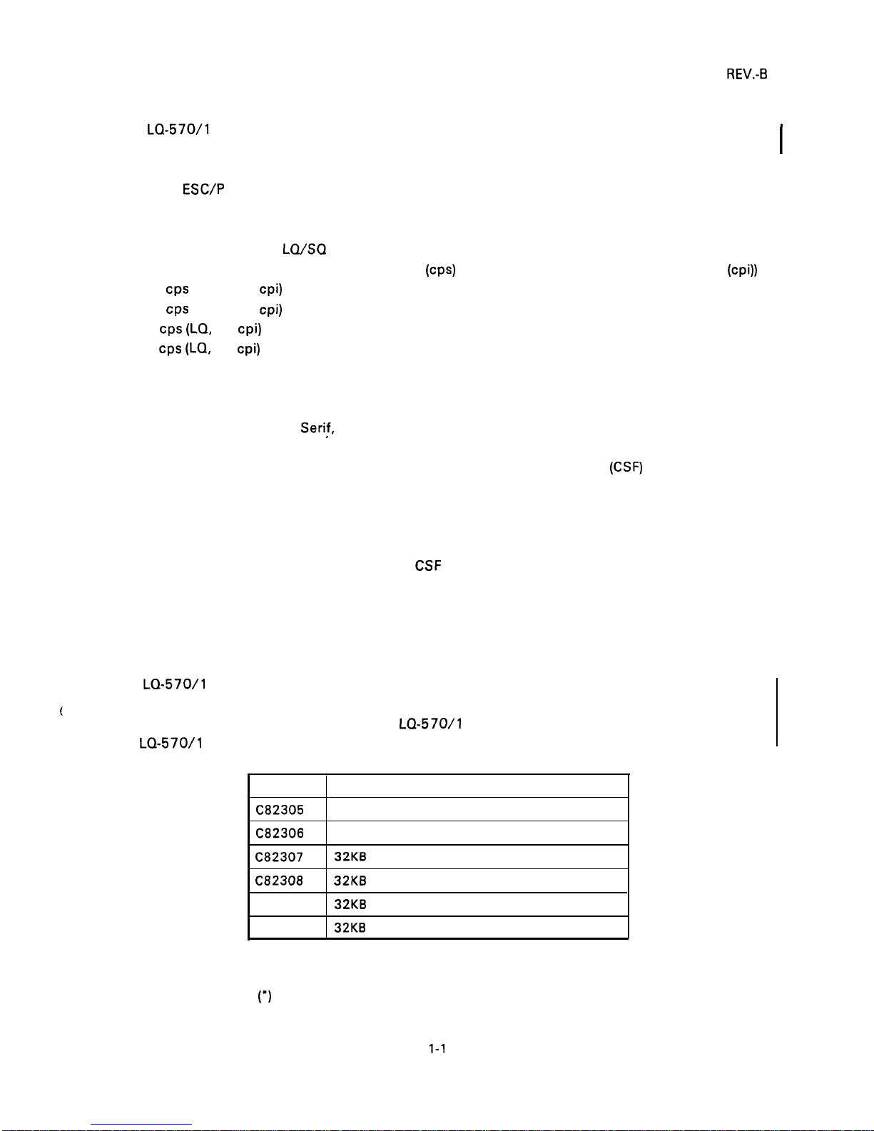
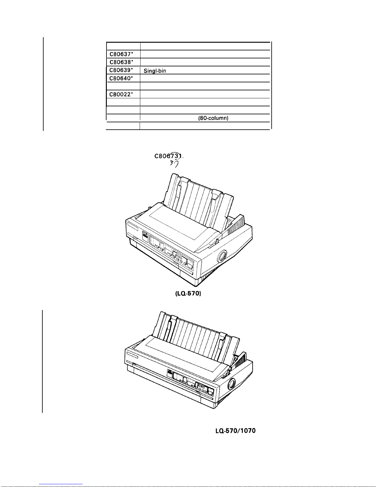
The
LQ-570/l
070 are equipped with the standard EPSON 8-bit parallel interface. Various interface
(
options ensure compatibility with a wide variety of computers. Table 1-1 lists the interface options, Table
1-2 lists the optional units available for the
LQ-570/l
070, and Figure 1-1 shows an exterior view of
the
LQ-570/l
070.
.
Table 1-1. Interface Options
Model
Description
C82305
Serial interface card (inch screw)
C82306
Serial interface card (mini screw)
C82307
32KB serial interface card (inch screw)
C82308
32KB serial interface card (mini screw)
C82310
32KB parallel interface card
C82313
32KB
IEEE-488 interface card
Printing is not possible for the following baud rates :
1800, 200, 134.5, 110, 75 bps.
NOTES: Refer to the “Optional Interface Technical Manual” for details.
The asterisks
(’)
in the table above represent the last digit of the part numbers. This digit varies,
depending on the country. For instance, in the U.S. the last digit is 1.
1-1
Page 10
REV.-B
Note:
Table 1-2. Optional Units
Model
Description
C80637*
Single-bin cut-sheet feeder (80-column)
C80638*
High-capacity cut-sheet feeder (80-column)
C80639*
SingI-bin
cut sheet feeder (1 36-column)
C80640*
High capacity cut sheet feeder (1 36-column)
C80019*
Tractor unit (80-column)
C80022*
Tractor unit (1 36-column)
7753
Fabric ribbon cartridge (80-column)
7754
Fabric ribbon cartridge (1 36-column)
7768
Film ribbon cartridge
(80-columd
1
7770
Film ribbon cartridge (1 36-column)
When a part number in the table above is followed by an asterisk (’), the last digit of the number
varies, depending on the country. For example, in the U. S., the model number for a single-bin
cut-sheet feeder (80-column) is
C80@.
3’7
(LQ-570)
(LQ-107O)
Figure 1-1. Exterior View of the
LQ-570/1070
1-2
Page 11
REV.-B
1.2 SPECIFICATIONS
This section provides specifications
1.2.1 Hardware
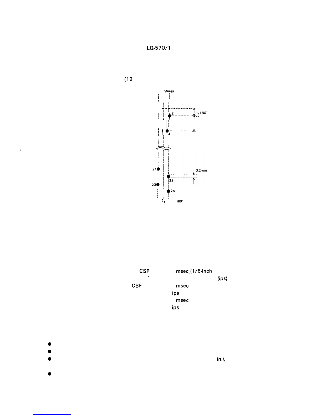
Printing method
Pin configuration
Feeding methods
Line spacing
Paper insertion
Paper-feed speed
for the
LQ-570/l
070 printer.
Specifications
Serial, impact, dot matrix
24 wires
(12
X 2 staggered, diameter 0.2 mm)
Wires 1 Wires 2
f~
II
1,
I
ii
- ------’$
j+--------
--
-1_
1/90”
/
~ j +L____
!!’’0’”
------$ ~
~
1/90”
\ ~ +;-------
‘
-
I
//
1:
/+
w
1/60” i
i
i
1
/60”
Figure 1-2. Pin Configuration
Friction feed (front/top)
Push tractor feed (rear)
Pull tractor feed (front/bottom)
Push-pull tractor feed (with optional tractor) (rear)
1/6 inch, 1/8, or programmable in units of 1/360 inch
Friction feed Front or rear side
Tractor feed Front,
Friction without
CSF
.
Friction with CSF
Tractor
NOTE: The points below provide precautions for
bottom, or rear side
77.6
msec.(1/6-inch
feed)
2.2 inches per second
(ips) (continuous)
77.6
msec (1/6-inch
2.2
ips
(continuous)
77.6
msec (1/6-inch
2.2
ips
(continuous)
handling paper.
1. Friction feed (release lever in FRICTION POSITION).
Paper must be loaded from the front or top entrance.
Do not use continuous paper.
feed)
feed)
Do not perform any reverse paper feeds within the top 8.5 mm (.34
in.),
bottom 22 mm (.87
(top entrance), or bottom 40.2mm (1.6 in.) (front entrance) area.
Do not perform reverse feeds greater than 1/6 inch after a paper end has been detected.
in.)
1-3
Page 12
REV.-B
● Use the paper tension unit.
● Do not use multi-part cut-sheet forms, except with front insertion.
● Do not perform reverse feeds greater than 1/6 inch when using envelopes.
2. Push tractor feed (release lever in REAR PUSH POSITION).
Paper must be loaded from the rear entrance.
Release the friction-feed mechanism.
Multi-part forms must be spot pasted beyond the perforation between the tractor holes.
Paper for multiple copies must be carbonless multi-part paper.
Use the paper tension unit.
Do not perform reverse feeds greater than 4/15 inch.
Since accuracy of paper feed cannot be assured after the paper end has been detected, please
do not perform reverse feeds after detection of a paper end.
3. Push-pull tractor feed (release lever in REAR PUSH POSITION).
Paper must be loaded from the front, rear, or bottom entrance.
Release the friction-feed mechanism.
Remove the paper tension unit and attach the pull tractor unit.
Ensure that there is no slack in the paper between the platen and the pull tractor.
Precisely adjust the horizontal position of the pull tractor and push tractor sprockets.
Paper for multiple copies must be spot pasted beyond the perforation between the tractor holes.
Paper for copies must be a carbonless multi-part paper.
Do not perform reverse feeds greater than 4/15 inch.
Do not perform reverse feeds after the paper end has been detected.
4. Pull tractor feed (release lever in PULL POSITION).
●
●
●
●
●
●
●
Paper must be loaded from the front or rear entrance.
Release the friction-feed mechanism.
Remove the paper tension unit and attach the pull tractor unit.
Insert the paper from either front or bottom.
Paper for multiple copies must be spot pasted beyond the perforation between the tractor holes.
Paper for copies must be a carbonless multi-part paper.
Do not perform reverse feeds.
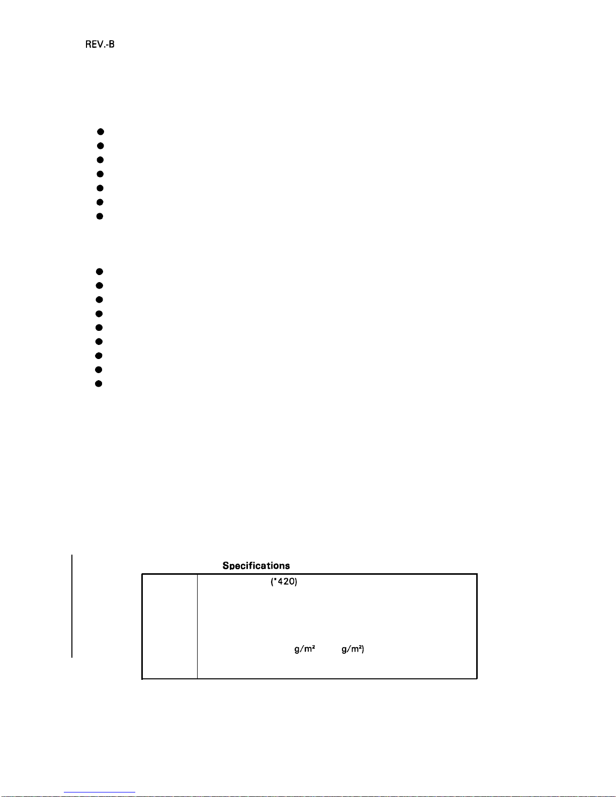
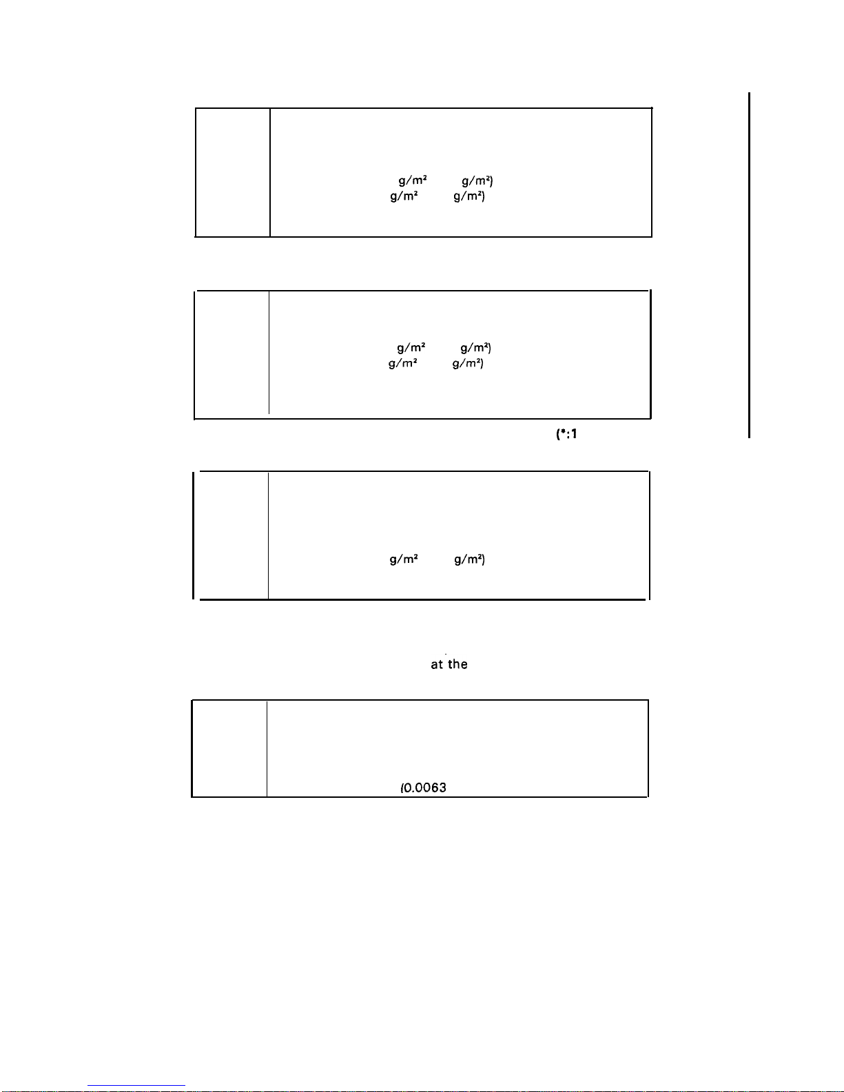
Paper specifications See tables 1-3, 1-4, 1-5, 1-6, and 1-7
Table 1-3.
S~ecifications
for Cut Sheets (One-Part Paper)
Width
Length
Thickness
Weight
Quality
148 mm to 257
(’420)
mm (5.8 in. to 10.1 (* 16.5) in.)
(top insertion)
182 mm to 257 (*364) mm (7.2 in. to 10.1 (* 16.5) in.)
(front insertion)
364 mm (1 4.3 in.), maximum
0.065 mm to 0.14 mm (0.0025 in. to 0.0055 in.)
14 lb. to 24 lb. (52.3
g/m2
to 90
g/m2)
Standard paper (photocopier paper, etc.)
Recycled paper (at normal temperatures)
(*136-column)
1-4
Page 13
REV.-B
Table 1-4. Specifications for Cut Sheets (Carbonless Duplicating Paper)
NOTES:
●
●
●
NOTES: ●
●
●
●
●
●
Width
Length
Thickness
Weight
Quality
Copies
182 mm to 216 (’364) mm (7.2 in. to 8.5 (* 14.3) in.)
257 mm to 297 mm (10.1 in. to 11.7 in.)
0.065 mm to 0.14 mm (0.0025 in. to 0.0055 in.) - single sheet
0.12 mm to 0.32 mm (0.0047 in. to 0.012 in.) - total
17 lb. to 24 lb. (52.3
g/m2 to 90
g/m2)
- single sheet
12 lb. to 15 lb. (40
g/m2 to 58
g\m2)
- each
Carbonless duplicating paper
4 sheets (1 original and 3 copies)
(*136-column
Table 1-5. Specifications for Continuous Paper
Width
101 mm to 254 (“406) mm (4.0 in. to 10.0 (* 16) in.)
Thickness
0.065 mm to 0.10 mm (0.0025 in. to 0.0039 in.) - single sheet
0.065 mm to 0.32 mm (0.0025 in. to 0.012 in.) -total
Weight 14 lb. to 22 lb. (52.3
g\m’
to 82
g/m2)
- single sheet
12 lb. to 15 lb. (40
g/m2 to 58
g/m2)
- each
Quality Standard paper or carbonless duplicating paper
Recycled paper (at normal temperatures)
Copies
4 sheets (1 original and 3 copies)
(*:1 36-column)
Table 1-6. Envelopes
Size
No. 6= 166 mm X 92 mm
No. 10= 240 mm X 104 mm
Thickness
0.16 mm to 0.52 mm (0.0063 in. to 0.0197 in.)
Differences in thickness within the printing area must be less than
0.25
mm (0.0098 in.)
Weight 12 lb. to 24 lb. (40
g/m2 to 91
g/m2)
Quality Bond paper, standard paper, airmail
Copies
Not available
Printing on envelopes is available only at normal temperatures and only using top insertion.
Keep the longer side of the envelope horizontal during insertion.
Place the left edge of a No. 6 envelope
at”the sheet guide setting mark.
Table 1-7. Label Specifications
Label size
Copies
Thickness
2 1/2 in. X 15/16 in.
4 in. X 15/16 in. “
4 in. X 1 7/16 in.
Not available
0.07 mm to 0.09 mm (0.0028 in. to 0.0031 in.) - base paper
0.16 mm to 0.19 mm
(0.0063
in. to 0.0075 in.) -total
Printing on labels is available only at normal temperatures.
Labels must be of the fanfold type.
Labels with pressure sensitive paper must be spot pasted beyond the perforation between
the tractor holes. The total thickness must be less than or equal to 0.3 mm (0.01 18 in.).
Labels can be printed out only if the temperature is between 5 and 35 degrees C (41 and
95 degrees F) and humidity is between 10 % and 80 % RH.
Examples of labels AVERY CONTINUOUS FORM LABELS
AVERY MINI-LINE LABELS
Labels must be used with the pull tractor (front or bottom).
Do not perform reverse feeds.
1-5
Page 14
REV.-B
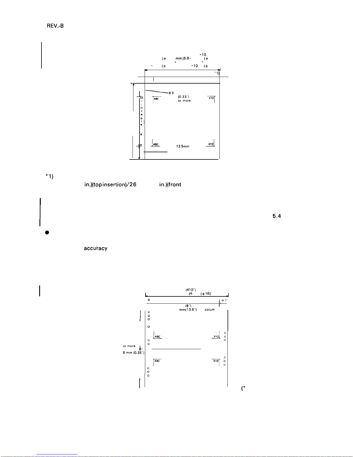
Printable area
See figures 1-3, 1-4, and 1-5
top insertion 148 - 257 mm (5.8
- 10.
1“)
148 - 257
(x
420) mm (5.8 - 10. 1“ {x 16.5))
front insertion 182
-
257 mm (7.2 - 10 1“)
182
-
257 (* 364) mm (7.2
- 10.
1“ (x 14.3’”))
.,
*
7
.,, Printable area max. 203.2 mm (8 in.)
-1 )
-1
4
~8.5
mm
‘
‘:
F
~’~~~’
7
“
t
364mm
;
(14.3”)
max.
:j
/,
*
.J-IJ&L
,,,mm
.A
(0.53”)
or more
v
Y
(* 136-column)
(80-column):
+1)
3.0 mm (O. 12 in.) or more when paper width is less than 229 mm (9 in.).
24 mm (0.9
in.)(top
insertion)\26
mm (1.0 in.)(front insertion) or more when paper width is 229 mm
(9.0 in.) to 257 mm (10.1 in.).
I
(136-column:)
3.0 mm (O. 12 in.) or more when paper width is less than 392 mm (1 5.4 in.). 29 mm (1.14 in.) (top
insertion) /31 mm ( 1.22 in.) (front insertion) or more when paper width is 392 mm (1
5.4
in.) to 420
mm (1 6.4 in.).
Paper-feed accuracy cannot be assured within 22 mm (0.87 in.) from the bottom edge of paper (top
insertion).
Paper-feed
accutacy cannot be assured within 40.2 mm (1 .58 in.) from the bottom edge of paper
(front insertion).
Paper-feed accuracy cannot be assured within 22 mm (0.87 in.) from the top edge of paper.
Figure 1-3. Printable Area for Cut Sheets
101.254 mm (4 10”)
L
101.254 x406)
(4. 10“ (x
16))
J
*
1*
Printable area
I*?
1’
Max. 203.2 mm
(8”):
80 column
1-
1
0
0
0
Printable 0
area
0
J-
0
0
0
9 mm (O 35”)
:
;r:’r;,3~,)
-:0
or more
t
0
0
c
Printable
:
area o
I
0
0
0
Max. 345.4 mm(i 3.6”): 136 cdum
0
0
0
0
0
0
L
0
0
0
0
0
0
0
0
0
0
(’
136-column)
Figure 1-4. Printable Area for Continuous Sheets
1-6
Page 15
REV.-B
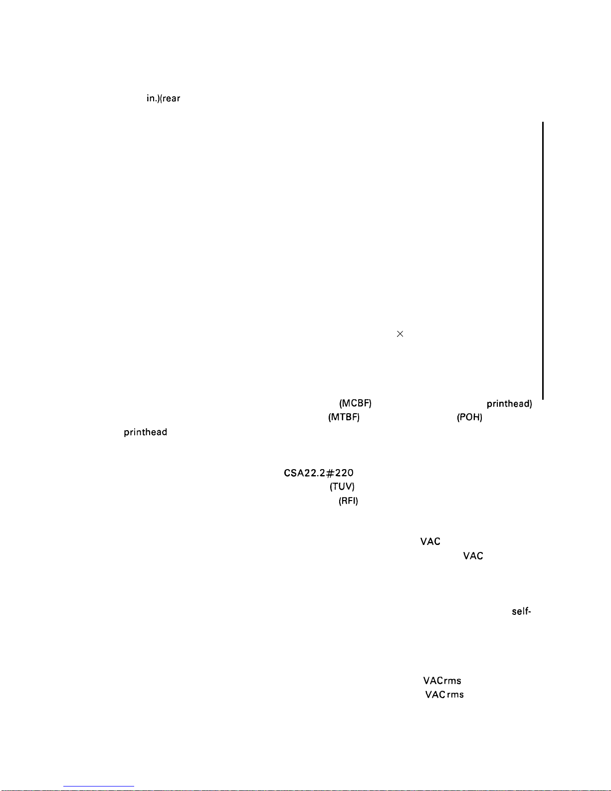
(80-column):
● 1) 13 mm (0.51 in.) or more when a paper width of 101 mm (4 in.) to 241 mm (9.5 in.) is used.
24 mm (0.9
in.)(rear insertion)\ 26 mm (1.0 in.)(front/bottom insertion) or more when a paper width
of 254 mm (10 in.) is used.
(1 36-column):
13 mm (0.51 in.) or more when a paper width of 101 mm to 401.3 mm (4 in. to 15.8 in.) is used.
15 mm or more when a paper width of 381 mm to 406 mm (15 in. to 16 in.) is used. 13 mm (rear
insertion) (0.5 1 in.) /1 7 mm (front/bottom insertion) (0.67 in.) is used. ( 136-column).
Ink ribbon
Type #7753 black ribbon cartridge (80-column)
#7768 film ribbon cartridge (80-column)
#7754 black ribbon cartridge (1 36-column)
#7770 film ribbon cartridge (1 36-column)
Color Black
Life 2 million characters at 48 dots/character (black ribbon)
(80-column) 0.2 million characters at 48 dots/character (film ribbon)
(136-column) 0.3 million characters at 48 dots/character (film ribbon)
Dimensions of ribbon cartridge
Fabric Type:
(80-column): 293 mm (W) X 34 mm (H)
X 72 mm (D)
(136-column): 468.3 mm (W) X 34 mm (H) X 72 mm (D)
Film Type:
(80-column): 293 mm (W) X 34 mm (H) X 72 mm (D)
(136-column): 468.5 mm (W) X 34 mm (H) X 72 mm (D)
Mean cycles between failures
(MCBF) 3 million lines (excluding printhead)
Mean time between failures
(MTBF) 4000 power on hours (POH) (25% duty)
200 million strokes (black ribbon)
100 million strokes (film ribbon)
Safety standards UL1 950 with D3 (U.S. version)
CSA22.2#220
EN 60950 (TUV) (European version)
Radio frequency interference
(RFI)
FCC class B (U.S. version)
VDE0871 (self-certification) (European version)
Reliability
Life of
printhead
Safety approvals
Electrical specifications
120 V version
Rated voltage
Input voltage range
Rated frequency
Input frequency
Rated current
Power consumption
insulation resistance
Dielectric strength
120
VAC
103.5 to 132
VAC
50 to 60 Hz
49.5 to 60.5 Hz
2.0 A
Approx. 33 W (during a
self-
test in draft mode, 10 cpi)
10 megohms, minimum (at 500
VDC between AC line and
chassis).
1000
VAC rms for 1 minute or
1200
VAC rms for 1 second
(between AC line and chassis)
1-7
Page 16

REV.-B
220 to 240 V version Rated voltage
Input voltage range
Rated frequency
Input frequency
Rated current
Power consumption
Insulation resistance
Dielectric strength
220 to 240
VAC
198 to 264
VAC
50 to 60 Hz
49.5 to 60.5 Hz
1.0 A
Approx. 33 W (during a self-test
in draft mode, 10 cpi)
10 megohms, minimum (at 500
VDC between AC line and chassis).
1250
VAC rms 1 minute or 1500
VAC rms 1 second (between AC
line and chassis)
Environmental
Temperature range 5 to 35 degrees C (41 to 95 degrees F) - operating
conditions
–30 to 60 degrees C (–22 to 140 degrees F)
– in shipment container
Humidity
10 to 80 % RH - operating
5 to 85 % RH – storage
Resistance to shock 1 G, within 1 ms – operating
2 G, within 1 ms - storage
Resistance to
0.25 G, 55 Hz, max. - operating
vibration
0.50 G, 55 Hz, max. - storage
Physical specifications (80-column):
Weight 6.1 kg,
approx. (13.5 Ibs., approx.)
Dimensions 434 mm (width) X 368 mm (depth) X 151 mm (height)
17.4 in. (width) X 14.7 in. (depth) X 6 in. (height)
(136-column):
Weight 8.4 kg,
approx. (1 8.6 Ibs., approx.)
Dimension 609 mm (width) X 368 mm
(depth)X
151 mm (height)
24.4 in. (width X 14.7 (depth) X 6 in. (height)
1-8
Page 17

REV.-A
1.2.2 Firmware Specifications
Control code
ESC/PTM level
ESC/P
2
(EPSON standard code for printers)
Printing direction
Bidirectional with logic seeking
Input data buffer
8KB (when SW 1-7 is OFF)
OKB (when SW 1-7 is ON)
Character code
8 bits
Character tables
Italic character table, PC 437, PC 850, PC 860, PC 863, PC 865
(PC indicates character table for personal computer)
Fonts and pitches
Bit-map fonts
EPSON Roman
10, 12, 15, proportional
EPSON Saris
Serif
10, 12, 15, proportional
EPSON Courier
10,
12,
15
EPSON Prestige
10, 12
EPSON Script
10, 12
EPSON Script C
proportional
OCR-B
10
EPSON Orator
10
EPSON Orator-S 10
EPSON Draft
10, 12, 15
Scalable fonts
EPSON Roman
8 pt to 32 pt
EPSON Saris Serif 8 pt to 32 pt
Printing modes
Selection and mixture of the following modes are allowed, excluding 15 cpi
condensed mode:
O Print quality (draft/letter quality)
O Character pitch (10, 12, 15, or proportional)
O Condensed
O Double-width
O Double-height
O Emphasized
O Double-strike
O Italic
O Underlined
O
Double-underlin~d
O Overscore
O Strike-through
O Outline
O Shadow
1-9
Page 18
REV.-B
NOTES: High-speed draft is valid if the printer status is as follows:
●
●
●
●
●
●
●
●
High-speed draft is selected by DIP switch.
Emphasized character mode is not selected.
Condensed character mode is not selected.
Draft is selected.
No D/L (download) characters are sent to the printer,
The horizontal dot space of characters is not set.
No bit image is sent to the printer.
Super/subscript is not selected.
(The printer switches back into normal mode to print emphasized, condensed, or download
characters and bit images.)
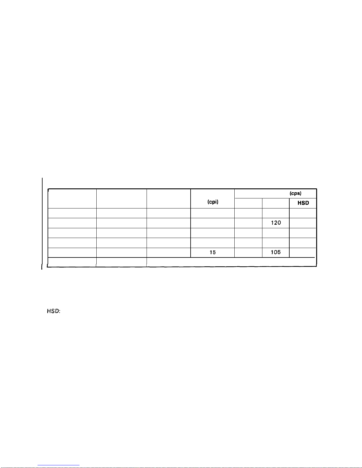
Printing speed See tables 1-8 and 1-9.
Printing columns See Table 1-8.
Character matrix See Table 1-10.
Character size See Table 1-10.
Table 1-8. Printing (Text Mode)
T
Printable Character Pitch
Printing Speed
(CPS)
Print Pitch
Condensed
Columns
(cpi)
Draft
LQ
HSD
10
0 80 (* 136)
10
210
70 225
1
137 (“233)
17.1
180 120 —
12
0
96 (* 164)
12
252 84 —
1
160 (*272)
20
210
140 —
15
0
120(”204)
15
315
105 —
1
Invalid
I
(* 136-column)
cpi:
characters per inch
Cps:
characters per second
LQ:
letter quality
HSD:
high-speed draft
1-10
Page 19
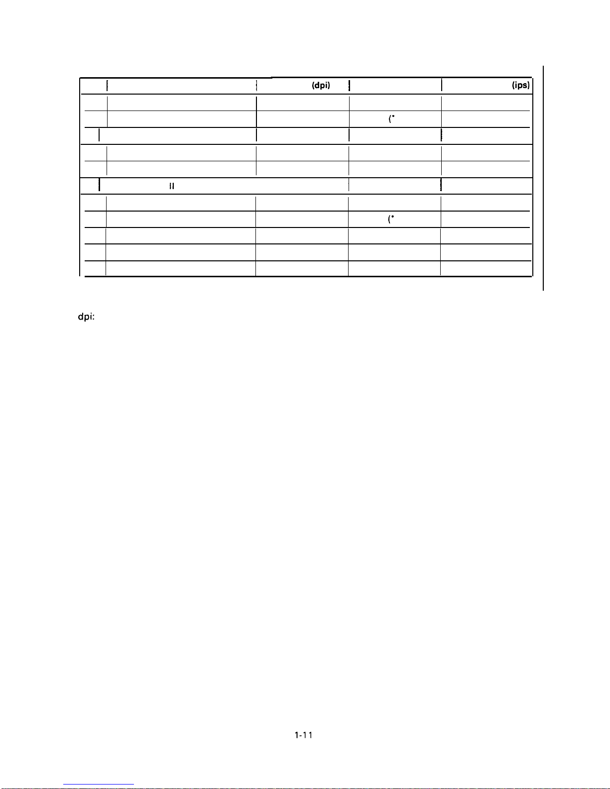
Table 1-9.
REV.-B
Printing (Bit Image Mode)
(
Pins
I
Bit Image Printing Mode
I
Density
(dpi)
}
Printable Dots
I
Printing Speed
(ips)
8
Single-density
60
480 (*8 16)
21.0
8
Dual-density
120
960
(“
1632)
10.5
8
I
Double-speed, dual-density
I
120
I
960 (“1632)
I
21.0
8
Quadruple-density
240
1920 (*3264)
10.5
8
CRT graphics
80 640 (“ 1088)
10.5
8
I
CRT graphics
II
I
90
I
720 (“1224)
I
14.0
24
Single-density
60
480 (*8 16)
21.0
24
Dual-density
120 960 (“ 1632) 10.5
24 CRT graphics II
90
720 (“224) 14.0
24
Triple-density
180
1440 (“2448) 7.0
I
24
Hex-density
360
2880 (*4896) 7.0
(* 136-column)
dpi: dots per inch
ips:
inches per second
1-11
Page 20
REV.-A
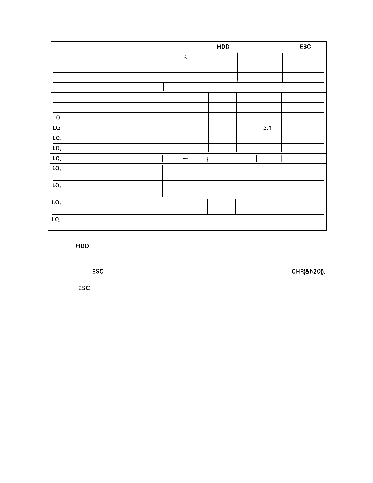
Table 1-10. Character Matrix and Character Size
Printing Mode
I
Face Matrix
I
HDD I Character Size I Unit
ESC
sp
High-speed draft, 10 pitch
7
x
22
90 2.0 x 3.1
—
Draft, 10 pitch
9 x 22 120
1.9 x 3.1
120
Draft, 12 pitch
9 x 22
120 1.9 x 3.1
120
I I
I
I
Draft, 15 pitch
7 X 16 120
1.0 X 2.3
120
Draft, 10 pitch, condensed
—
240
—
120
Draft, 12 pitch, condensed
—
240
—
120
LQ,
10 pitch
31 x 22 360 2.2 x 3.1 180
LQ,
12 pitch
27 X 22 360
1.9 x
3.1
180
LQ,
15 pitch
22 X 16
360 1.6 X 2.3
180
LQ,
10 pitch, condensed
—
360
—
180
LQ,
12 pitch, condensed
l–
I
360
I
–
I
180
LQ,
proportional Max. 37 X 22
360
2.6 X 3.1
180
Min. 18 X 22
360
1.0 x 3.1
LQ,
proportional, condensed
—
360
—
180
—
360
—
LQ,
proportional, super/subscript
Max. 28 X 16 360 1.8 X 2.3 180
Min. 12 X 16 360 0.7 X 2.3
LQ,
proportional, super/subscript,
I
—
I
360
I
—
I
180
condensed
—
360
—
NOTES: .
HDD is horizontal dot density in dots per inch.
● Face matrix and character size indicate the size of the maximum character. This value is
dependent on paper, ribbon, etc.
● Unit ESC sp (which also can be sent as unit, followed by the character string CHR(&h20)),
indicates the minimum length to be added to the right of the character specified with the
ESC
sp control code.
● “-”
indicates that the character matrix is reshaped by printer firmware. Character width
becomes half of the noncondensed character width.
1-12
Page 21
REV.-A
1
2
3
4
:
7
8
9
10
11
12
13
14
15
16
17
18
19
20
21
22
23
24
(Typical draft character)
L
E
F
T
s
P
A
c
E
Ascender area
!-
Descender area
I
.
R
I
G
H
T
s
P
A
c
E
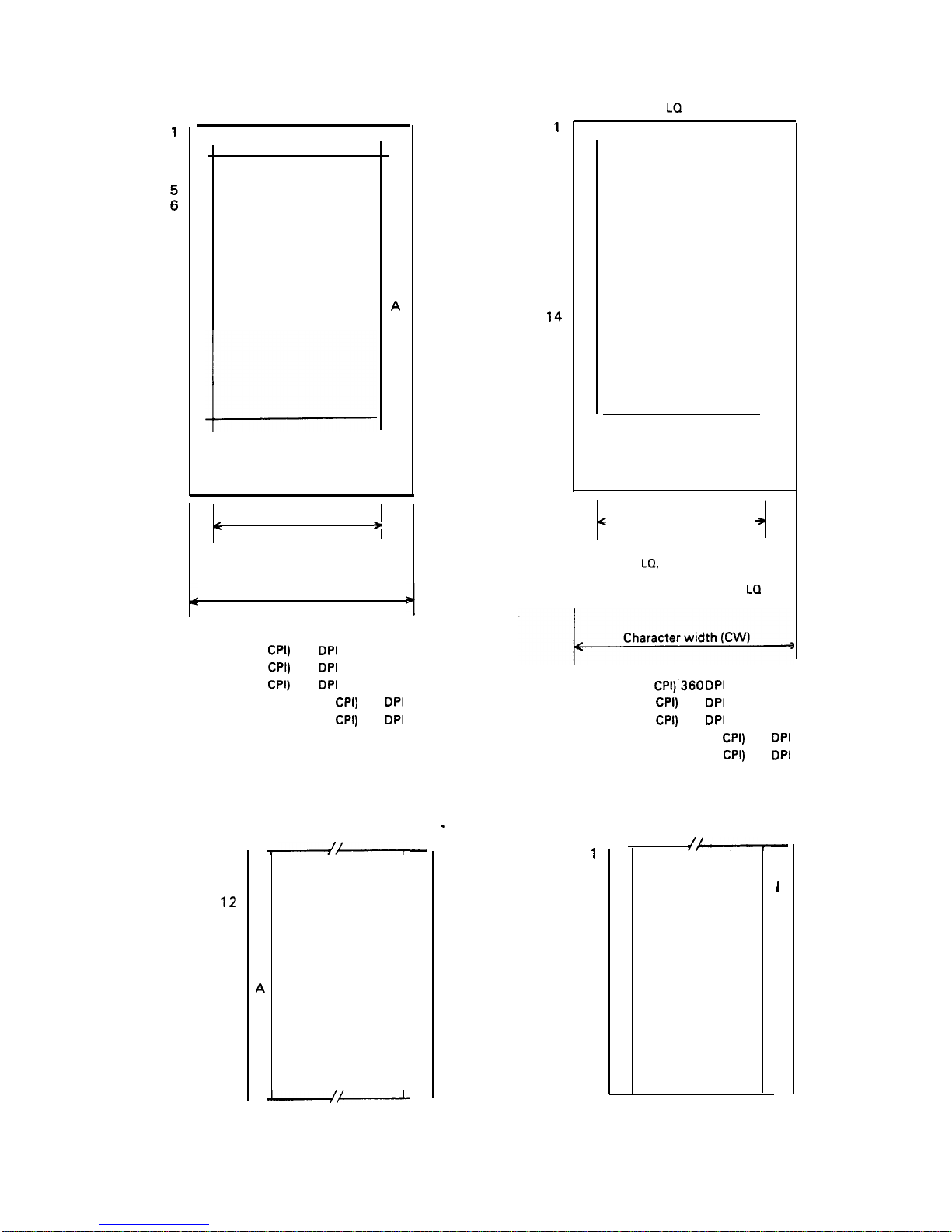
Face width
<
9
dots
>
Character width (CW)
12 dots (10
CPI)
120
DPI
15 dots (12
CPI)
180
DPI
16 dots (15
CPI)
240
DPI
14 dots (condensed 10
CPI)
240
DPI
12 dots (condensed 12
CPI)
240
DPI
9
10
11
12
13
14
15
16
17
18
19
20
21
22
23
24
L
E
F
T
s
P
A
c
E
(Subscript character)
—
R
I
G
H
T
s
P
A
c
E
—
1
2
3
4
5
6
7
8
9
10
11
12
13
14
15
16
17
18
19
20
21
22
23
24
(Typical LQ character)
L
E
F
T
s
P
A
c
E
Ascender area
I
Descender area
R
I
G
H
T
s
P
A
c
E
Face width
<
9
29 dots
(Typical
LQ,
excluding 15 pitch)
15 dots for
15 pitch and condensed
La
+
36 dots (10 CPI)’360
DPI
30 dots (12
CPI)
360
DPI
24 dots (15
CPI)
360
DPI
21 dots (condensed 10
CPI)
360
DPI
18 dots (condensed 12
CPI)
360
DPI
.
1
2
3
4
5
6
7
8
9
10
11
12
13
14
15
16
L
E
F
T
s
P
A
c
E
(Subscript character)
—
R
I
G
H
T
s
P
A
c
E
—
Figure 1-5. Character Matrix
1-13
Page 22
REV.-A
1.3 INTERFACE OVERVIEW
The printer has a parallel interface with the specifications described below.
1.3.1 Parallel Interface
Specifications for the 8-bit parallel interface are as follows:
Data format
Synchronization
Handshaking
Signal level
Adaptable connector
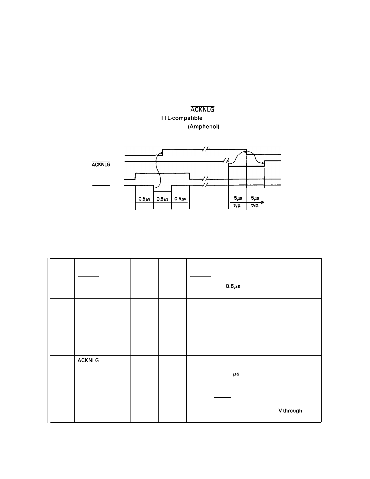
Data transmission timing
BUSY
ACKNLG
DATA
STROBE
8-bit parallel
STROBE signal
BUSY and
ACKNLG signal
TTL-compatible
57-30360 (Amphenol) or equivalent
See Figure 1-6.
{
~;
o.5/is
o.5Lls
0.5/S
5/S
5/.fs
min.
min.
min.
typ.
typ. ‘
Figure 1-6. Data Transmission Timing
Table 1-11 shows the connector pin assignments and signal functions of the 8-bit parallel interface.
Table 1-11. Connector Pin Assignments and Signal Functions
Pin No.
Signal Name
Return
Pin No.
Dir. Functional Description
1
STROBE
19
IN
STROBE pulse to read the input data. Pulse width must
be more than 0.5ps. Input data is latched at falling
edge of this signal.
2
DATA 1
20
IN
Parallel input data to the printer.
3
DATA 2
21
IN
HIGH level means data 1.
4
DATA 3 22
IN
LOW level means data O.
5
DATA 4 23
IN
6
DATA 5 24
IN
7
DATA 6 25
IN
8
DATA 7 26
IN
9
DATA 8
27
IN
10
ACKNLG
28
OUT
This pulse indicates data has been received and the
printer is ready to accept more data. Pulse width is
approximately 11
Ks.
11
BUSY
29
OUT
HIGH indicates the printer cannot accept more data.
12
PE
30
OUT
HIGH indicates paper out. This signal is effective only
when the ERROR signal is LOW.
13
SLCT
—
OUT
Always HIGH output. (Pulled up to +5
Vthrough
a 3.3K
ohm resistor.)
1-14
Page 23
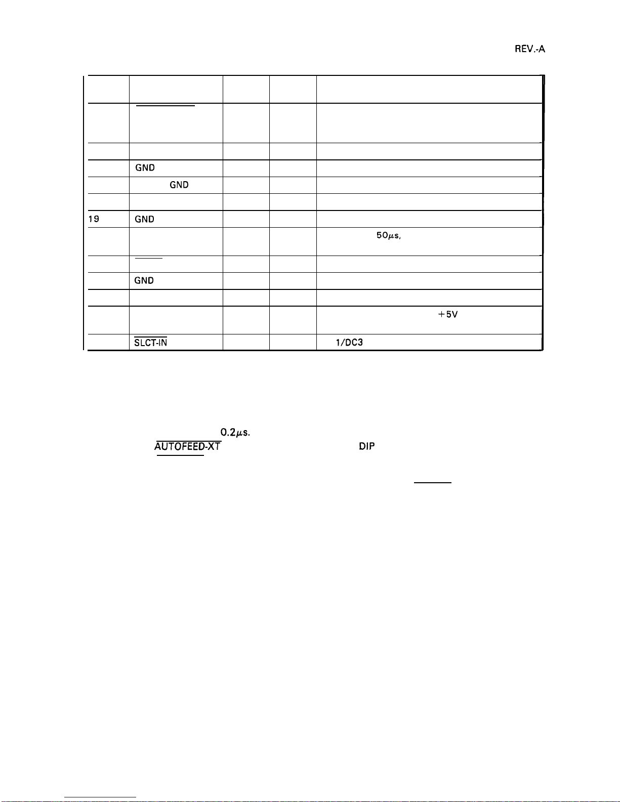
Table 1-11. Connector Pin Assignments and Signal Functions (Cont.)
Pin No. Signal Name
Return
Pin No.
Dir.
Functional Description
14 AUTO FEED-XT
—
IN
If LOW when the printer is initialized, the printer
automatically performs a line feed upon input of the
CR code (Auto LF).
15
Not used.
16
GND
—
Ground for twisted-pair grounding.
17
Chassis
GND
—
—
Chassis ground level of printer.
18
Not used.
19
to 30
GND
Ground for twisted-pair grounding.
31
I NIT
16
IN
Pulse (width: 50ws, min., active LOW) input for printer
initialization.
32
ERROR
OUT
LOW indicates an error has occurred in the printer.
33
GND
—
—
Ground for twisted-pair grounding.
34
Not used.
35
OUT
Always HIGH. (Pulled up to
+5V
through 3.3K ohm
resistor.)
36
SLCT-IN
—
IN
DC
l\DC3
control is disabled.
NOTES: 1. “Dir.” indicates the direction of the signal flow as viewed from the printer.
2. “Return Pin No.” denotes a twisted-pair return line.
3. The cable used must be shielded to prevent noise.
4. All interface conditions are based on TTL levels. Both the rise and fall times of all signals
must be less than
0.21.Ls.
5. The AUTOFEED-XT signal can be set to LOW by DIP switch 2-4.
6. The SELECT-IN signal can be set to LOW by jumper 3.
7. Printing tests, including those of the interface circuits, can be performed without using
external equipment by setting DATA 1- DATA 8 pins to the STROBE signal.
1-15
Page 24
REV.-A
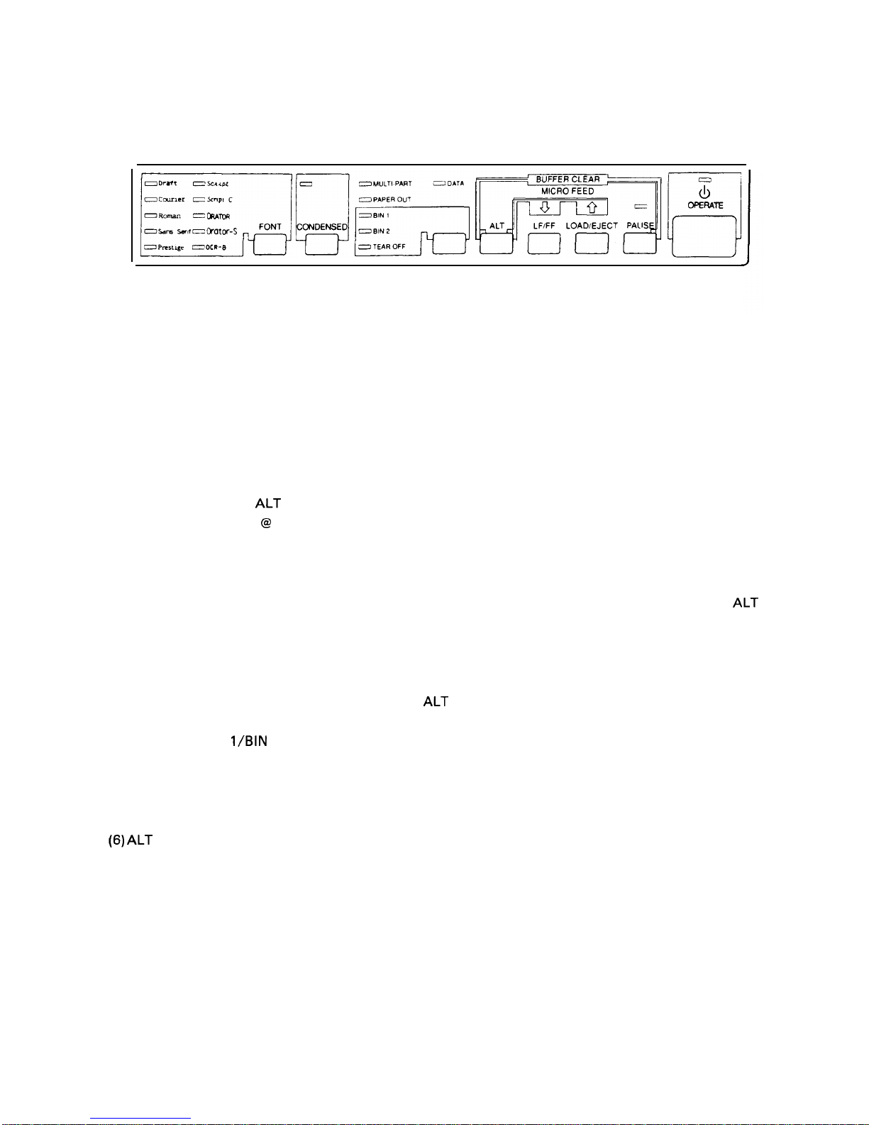
1.4 CONTROL PANEL
On the control panel are: a power button (labeled OPERATE), 7 non-lock type buttons, and 19 indicators.
Figure 1-7. Control Panel
BUTTONS
(1) OPERATE Button
This button turns on the power supply to the printer.
(2) PAUSE Button
This button controls printer action. Pressing the button toggles the printer between PAUSE condition
(no printing, no paper feeding, and not accepting data) and RUNNING. This button is also used in
conjunction with the
ALT button as a buffer clear to clear the input buffer and perform software
initialization, as if ESC
@
had been received.
(3) LINE FEED/FORM FEED Button
Pressing this button performs a line feed, and holding down the button performs a form feed,
irrespective of the PAUSE/RUNNING condition. This button is also used in conjunction with the
ALT
button as the micro reverse feed.
(4) LOAD/EJECT Button
Pressing this button loads or ejects the paper. Refer to Section 1.6.8, Sheet Loading and Sheet Ejection.
This button is also used in conjunction with the
ALT button as the micro forward feed.
(5) TEAR-OFF/BIN
l\BiN
2 Button
In tractor-feed mode, pressing this button advances continuous paper to the tear-off position, and the
TEAR-OFF indicator is lit. In friction-feed mode, pressing this button toggles between bin 1 and bin 2,
and the selected BIN indicator is lit.
(6) ALT Button
This button is used only in combination with another button,
1-16
Page 25

REV.-A
(7) FONT Button
Pressing this button selects a font, and pressing it continuously selects the next one, sequentially. The
FONT LED indicates the currently selected font.
(8) CONDENSED Button
Pressing this button toggles the printing mode between normal and condensed, alternatively.
NOTE: Selections of the FONT and CONDENSED buttons
and the CONDENSED selection become effective
INDICATORS
(1) OPERATE (green)
are stored as defaults, so that the last FONT
when the printer is initialized.
Lit when the printer’s OPERATE button is on, and AC power is supplied.
(2) PAUSE (orange)
Lit
(3)
Lit
(4)
Lit
(5)
when the printer is in PAUSE-mode (no printing, no paper feeding, and not accepting data).
TEAR-OFF (orange)
when the sheet is advanced to the tear-off position.
DATA (orange)
when the printer has received data from the host. .
PAPER-OUT (red)
Lit when the paper-out detector senses no paper. Refer to Section 1.6.3, Paper-out Detection and Forms
Override Function.
(6) MULTI-PART (green)
Lit when the adjust lever is
(7) BIN 1 (green)
Lit when bin 1 is selected.
(8) BIN 2 (green)
Lit when bin 2 is selected.
positioned at the 4th step or higher,
(9) FONT (green) - Draft, Courier, Roman, Saris Serif, Prestige, Script, Script C, Orator, Orator-S, OCR-B
These indicators show the currently selected font.
(10) CONDENSED (green)
Lit when condensed mode is selected.
1-17
Page 26
REV.-A
1.5 DIP SWITCHES AND
This section describes the DIP switch
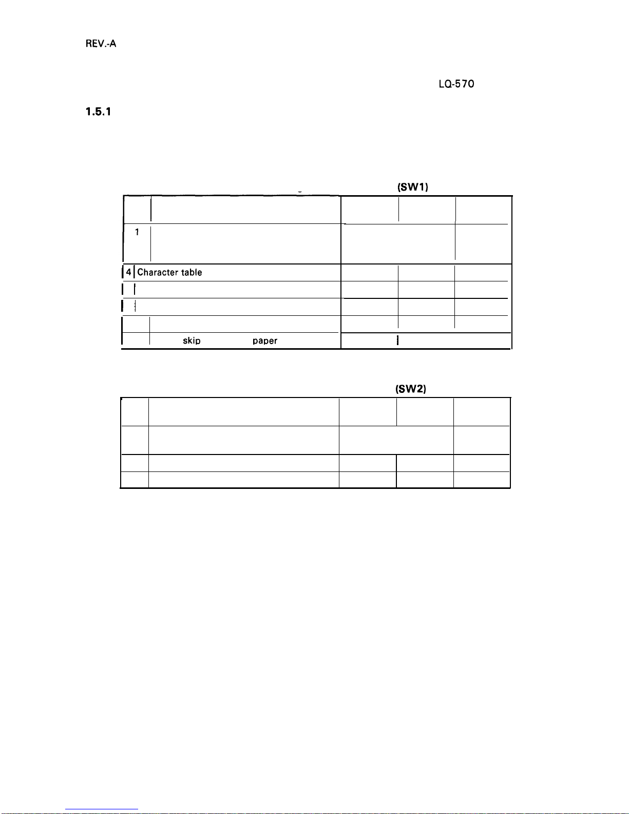
1.5.1
DIP Switch Settings
JUMPER SETTING
selections and jumper setting for the
LQ-570
printer.
The two DIP switch banks for the printer, located on control panel, function as shown in tables 1-12
through 1-15. (Note that the status of the DIP switches is read only at power on or upon receipt of the
INIT signal.)
Table 1-12. Settings for DIP Switch 1
(SW1)
No.
I
Description
1
2
International character set and PC selection
3
I 4 I
Charactertable selection
I
5 I Graphic print direction
I
6 I High-speed draft
7
Input buffer
8
l-inch
skiD
continuous
~aDer
ON
OFF
Factory
Setting
ON
See Table 1-14.
ON
ON
Graphic
Italic
OFF
Unidir.
Bidir.
OFF
Invalid Valid
OFF
Invalid Valid
OFF
ON
I
OFF
I
OFF
Table 1-13. Settings for DIP Switch 2
(SW2)
t
No.
Description
ON
OFF
Factory
Setting
1
Page length of continuous paper
See Table 1-15.
OFF
2
OFF
3
Auto tear-off
ON
OFF
OFF
4
Auto LF
ON
OFF OFF
1-18
Page 27
REV.-A
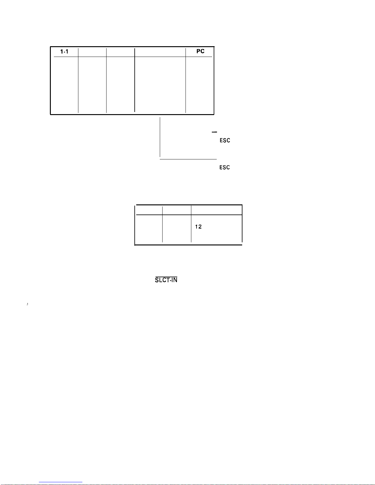
Table 1-14. International Character Set Selection
1-1
1-2 1-3
Country
Pc
ON
ON ON
Us.
437
ON
ON
OFF
France
850
ON
OFF ON
Germany
860
ON
OFF
OFF
U.K.
863
OFF
ON ON
Denmark 1
865
OFF
ON
OFF
Sweden
(437)
OFF
OFF
ON
Italy
(437)
OFF
OFF OFF
Spain 1
(437)
L
—
When SW 1-4 is OFF,
If graphic table was selected by
ESC
t 1, PC becomes 437.
When SW 1-4 is ON,
if italic table was selected by
ESC
t O, country setting becomes U.S.
Table 1-15. Page Length
2-1
2-2
Page Length
OFF
OFF
11 inches
ON OFF
12
inches
OFF
ON
8.5 inches
ON ON
70/6 inches
1.5.2 Jumper Setting
If Jumper 3 is connected to GND, the SLCT-IN signal is fixed to LOW.
1.
1-19
Page 28
REV.-A
1.6 OPERATING INSTRUCTIONS
This section describes the self-test and hexadecimal dump functions and also includes the error states,
printer initialization, and buzzer operation.
1.6.1 Self-Test
To run the self-test using draft mode, turn the printer on while pressing the LOAD/EJECT button. To
run the self-test using the letter quality (LQ) mode, turn the printer on while pressing the LINE
FEED\FORM FEED button. You can stop or start self-test printing by pressing the PAUSE button. When
you are satisfied with the self-test, stop the printing by pressing the PAUSE button and turn the printer
off.
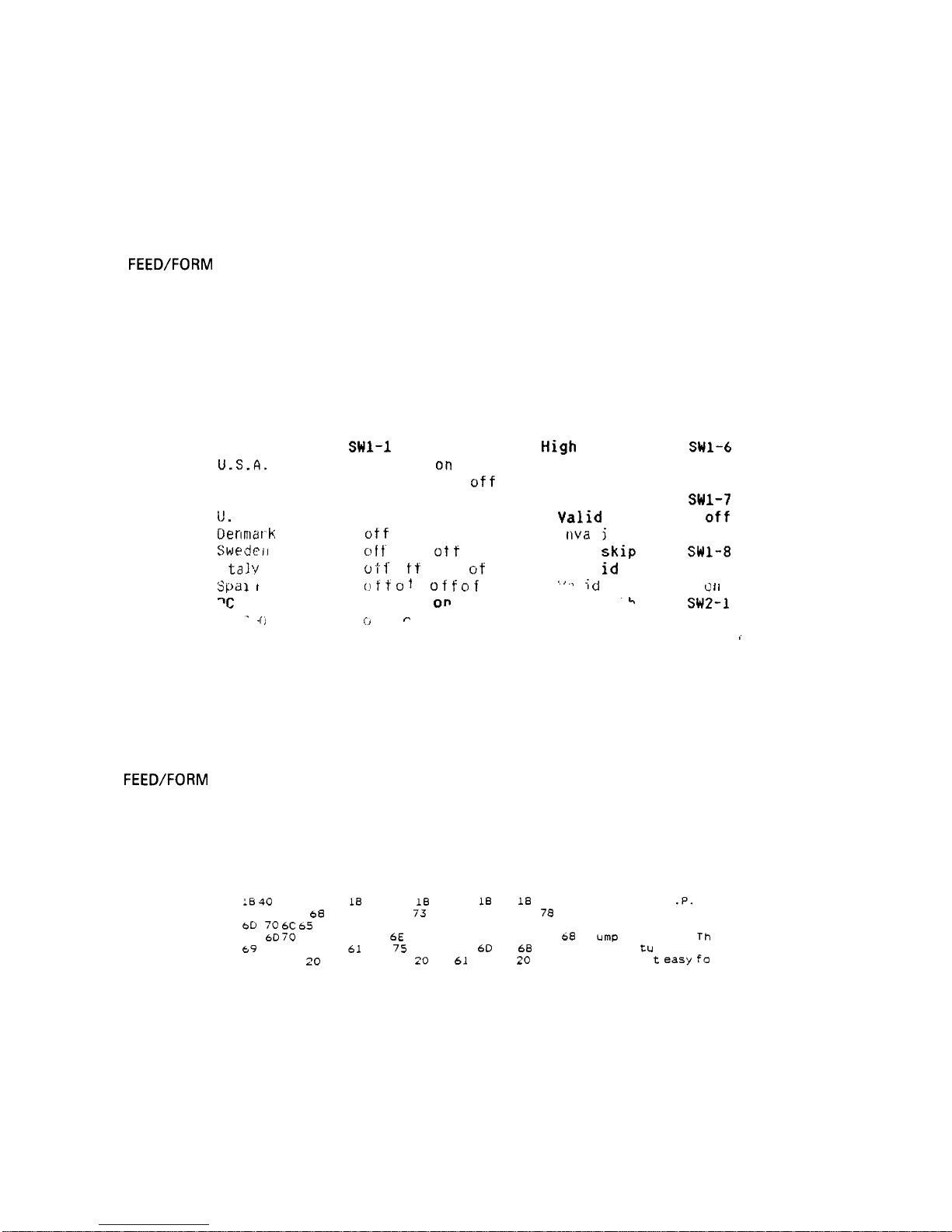
The firmware revision number is printed on the first line of the self-test, followed by the current DIP
switch settings.
Xxxxxx
Country/PC
U.S.A.
France
German
y
(J.
K .
Oe nma r k
Swedeil
I
ta 1 ?
S pd 1
i
I
‘c
437
‘-
.
.
(j
Swl-1
1-2 1“3 1-4
on on
on
off
o n o n off
off
on
off Orl
off
on
off off off
off
on on
off
o f f“
o n
Ot f
oft
o
t f’ o I t o n
of
f
(,I f f ~ t
f ~ f f ~ f f
on on
on
,:.)
I I
~
High
speed draft
SWI-6
Va 1
id
off
Invalid on
Receive buffer SW1-7
Valid
off
I
nva
1
i
d
o n
1 inch
skip
SW1-8
1 rival
id
off
‘ ~ ~
I ;
~
to f I
k
SW2-1 2-2
off off
~
t i
Figure 1-8. Self-Test Printout
1.6.2 Hexadecimal Dump Function
To put the printer in hex. dump mode, power it on while pressing both the LOAD\ EJECT and LINE
FEED\FORM FEED buttons. In hex. dump mode, the printer prints out the hexadecimal representation
of the input data, along with the corresponding ASCII characters. This function is valuable for checking
the data the printer has received from the host. If input data is a nonprintable character code, a period
(.) is printed in the ASCII column.
:6 40
LB 52 00 IB
20 20 54
68
69 73
bD
70 6C 65 20 6F
75
6D 70
20 70 72
69
73 20 66 65
61
0.4 20 20 20 20 20
74 01
IB
36 12 LB 50 18 70
20 69
73 20 61 6E 20 65 78
66 20 61 20 64 61 74 61 20
69
6E 74 6F 75 74 2E 20 54
74
75
72 65 20 6D 61 6B 65
69 74
20
65 61 73 79 20 66
Figure 1-9. Hexadecimal Dump
00
.@. R. . t. .6.
.P.
D.
61
This is an exa
64
mple of a data d
60
ump printout. Th
73 is f ea
tu
re makes
6F .
i
t easy fo
Function
1-20
Page 29

REV.-A
1.6.3
Paper-out Detection and Forms Override Function
When the paper-out detector, attached to the printer mechanism, detects a paper-end, the printer first
performs a forms override. If paper loading fails, the BUSY signal goes HIGH, the PAPER OUT indicator
is lit, the interface PE signal becomes HIGH, the ERROR signal becomes LOW, and the printer enters
the PAUSE condition automatically.
By ignoring the paper out, the printer can print additional lines after the paper out is detected. This
function is called the forms override function. After you load new paper and press the PAUSE button,
the printer recovers to the RUNNING condition, and printing restarts.
The printer enters the paper-out condition only when a paper-out is detected after the printer performs
paper loading.
1.6.4 Error Conditions
If any of the following error conditions are detected, the printer automatically enters PAUSE condition.
●
●
●
●
Home position is not detected at printer mechanism initialization.
Home position is detected during printing.
The PAUSE button is pressed, and the printer enters PAUSE condition.
A paper-out is detected after performing paper loading operation.
If parallel interface is selected, the following interface signals are output to indicate the error and to
stop data transmission:
The BUSY signal becomes HIGH.
The ERROR signal becomes LOW.
No ACKNLG pulse is sent.
1.6.5 Buzzer Operation
The buzzer sounds under the following conditions:
. A paper-out error is detected (beeps 3 times for 0.1 second, with 0.1 second intervals).
● Abnormal carriage movement is detected (beeps 5 times for 0.5 second, with 0.5 second intervals).
● A panel setting is accepted
1.6.6
Printer Initialization
There are three initialization
initialization.
(1) Hardware initialization
(O. 1 second beep).
methods: hardware
initialization, software initialization, and panel
This type of initialization takes place when the printer power button is turned on (and the AC power
cord is plugged in) or when the INIT signal is received.
When the printer is initialized, it performs the following actions:
1-21
Page 30

REV.-A
(a) Initializes printer mechanism.
(b) Clears input data buffer.
(c) Clears downloaded character set.
(d) Clears print buffer.
(e) Returns printer settings to their default values.
(2) Software initialization
Input of the
ESC @
command also initializes the printer. Printer initialization by ESC @ code does not
perform functions (a), (b), and (c) above. The settings changed by the last
SelecType
operation are
maintained.
(3) Panel initialization
This printer can be initialized by pressing the PAUSE button in combination with the ALT button. When
the printer is initialized from the front panel, functions (a) and (c) above are not performed. The settings
changed by the last
SelecType
operation are maintained.
1.6.7 Default Values
When the printer is initialized, the following default values are set:
Page position
Left and right margins
Line spacing
Vertical tabs
Horizontal tabs
Family number of type style
Download characters
Character spacing
Printing effects
Condensed printing
Printer condition
The current paper position becomes the top-of-form position
Released
1/6 inch
Cleared
Every 8 characters (relative)
Last font selected from the panel
Kept - software initialization
Cleared – hardware initialization
10 cpi
Cleared, except condensed printing
Last setting selected from the panel
RUN
1.6.8 Sheet Loading and Sheet Ejection
The release lever can disengage the pull-tractor unit drive mechanism, giving this printer improved
paper-handling for functions that utilize the release lever. These functions are described below:
Automatic cut-sheet loading without the cut-sheet feeder
Move the release lever to the friction-feed position, and place the sheet along the paper guide (top or
front). A few seconds later, the sheet is automatically loaded to the top-of-form position and the printer
enters the RUNNING condition.
1-22
Page 31

REV.-A
Automatic cut-sheet loading and ejection with cut-sheet feeder
Move the release lever to the friction-feed position, and place the sheets into the hopper of the cut-sheet
feeder. Pressing the LOAD/EJECT button loads one sheet to the top-of-form position. If a paper-out is
detected before printing starts, a sheet will again be loaded automatically to the top-of-form position.
Continuous paper loading and ejection
(backout)
Move the release lever to the REAR PUSH position, and insert the paper into the tractor unit. Pressing
the LOAD/EJECT button loads the paper automatically to the top-of-form position. If a paper-out is
detected before printing starts, the paper will be loaded automatically to the top-of-form position.
If the LOAD/EJECT button is pressed after continuous paper has been loaded, the paper is ejected
backward to the push tractor unit. To back out several pages, press the LOAD/EJECT button several
times. Each time LOAD/EJECT is pressed, reverse feed is performed for a single page.
When the paper is at the current setting for the top-of-form position, the top-of-form adjustment function
is valid for the next loaded
positicrn.
At this time, the LOAD\ EJECT button advances the paper forward,
and the LINE FEED/FORM FEED button moves the paper backward.
The adjusted top-of-form position for continuous paper is saved in EEPROM, but the setting for cut sheet
paper is not saved.
1.6.9 Tear-off Function
The below tear-off function is limited under the push tractor mode.
Auto-tear-off
The auto-tear-off function is enabled by DIP switch setting. When this function is enabled and the release
lever is in the tractor position, the paper advances to the tear-off position automatically if the input data
buffer is empty and the printer is in the RUNNING condition. The TEAR-OFF LED lights to indicate that
you can use the LOAD/EJECT and LINE FEED/FORM FEED buttons, in combination with the ALT button,
for backward and forward micro feed adjustment.
Using micro feed, adjust the paper to meet the tear-off edge. Once the tear-off position is set, this setting
remains valid even after the printer is turned off or initialized. If subsequent data is sent to the printer,
the paper returns to the original position automatically and printing starts. If the PAUSE button is pressed
while the paper is advanced to the tear-off position, the paper returns to the original position (and the
printer enters the PAUSE condition).
1-23
Page 32

REV.-B
Short-tear-off
To access the short-tear-off function, press the TEAR-OFF button. The release lever must be in the tractor
position. The paper advances to the tear-off position whether the printer is in PAUSE or RUNNING
condition. At this time, the TEAR-OFF LED lights to indicate that you can use the LOAD/EJECT and LINE
FEED/FORM FEED buttons, in conjunction with the ALT button, for backward and forward micro feed
adjustment. Using micro feed, adjust the paper to meet the tear-off edge. Once the tear-off position
is set, this setting remains valid even after the printer is turned off or initialized. If subsequent data is
sent to the printer and the printer is in the RUNNING condition, the paper returns to its original position
automatically and printing starts. If the TEAR-OFF button is pressed again while the paper is advanced
to the tear-off position, paper returns to its original position whether the printer is in PAUSE or RUNNING
condition.
I 1.6.10 LEVER, G, ADJUST Operation
The LEVER ,G, ADJUST must be set to the proper position for the paper thickness. If this lever has been
set to the 4th step or higher, printing speed is reduced and the head energy is increased.
Table 1-16. Lever Positions
I
Lever Position
I
Paper Thickness
I
I
NOTE: If printing density becomes lighter, adjust the LEVER, G, ADJUST position one step higher.
1 position (3rd step)
A
,DJUST
Figure 1-10. Lever Positions
1-24
Page 33

REV.-A
1.6.11 Printer Protection
for Heavy-Duty Printing
This printer has a printhead protection function to prevent it from overheating and to protect the printer
when the head driver voltage drops. If head temperature exceeds its maximum value, printing stops
automatically until the head temperature drops to a certain value before printing resumes. Printing
resumes at a lower print speed at first.
However, as the head temperature decreases, print speed increases to normal speed automatically. If
the head temperature continues to increase at the lower speed, printing is stopped or resumed as
temperature increases or decreases.
If the voltage supplied to the head drive circuit drops below its minimum limit as a result of heavy-duty
printing, printing is interrupted immediately. When the power supply voltage recovers to a certain value,
the remaining print line is printed at half speed. This protective action occurs when half or more of the
wires are activated continuously.
1-25
Page 34

REV.-B
1.7 MAIN COMPONENTS
I
I
The main components of the
LQ-570/l
070 printers are designed
to maintain and repair the printer. The main components are:
for easy removal and replacement
1)
C062
MAIN board:
the main control board; the CPU on this board controls all main functions.
2)
C062
PNL board:
the control panel board.
3)
C062 PSB\PSE
board:
the power supply board.
4) M-5
E10/5E60:
the printer mechanism.
C062 PSB/PSE Board
C062 MAIN Board
&
I
r
1
,Y
7
,U
“.0
l-l
i
9
p u
xx &
1-
d -1
rlq
i\ ~
h 11 J \
Printer Mechanism M-5E60
Printer Mechanism
M-5E
10
(LQ-570)
(LQ-1
070)
Figure 1-11.
LQ-570/1070
Component Layout
1.7.1
C062
MAIN Board (Main Control Circuit Board)
The
C062
MAIN Board for the
LQ-570
consists of a TMP90C041 N 8-bit CPU, an E05A50 gate array,
a PROM (5 12K), a PSRAM (256 K), a mask ROM (character generator,
2M),
an EEPROM, and a hybrid
IC (STK-6022B).
In addition to this, the board for the
LQ-1
070 also includes a SRAM (64 K).
(80-column)
Figure 1-12.
C062
MAIN
(1 36-column)
Board (80-column and 136-column)
1-26
Page 35

REV.-B
1.7.2
C062 PNL
Board (Control Panel Circuit Board)
The
C062
PNL board is the
LQ-570\1070
control panel, which includes the indicator
LEDs,
switches, I
and DIP switches.
Figure 1-13.
C062 PNL
Board
1.7.3
C062
PSB/PSE Board (Power Supply Circuit Board)
The power supply unit consists of a switching regulator circuit, which converts the AC line voltage to
the DC voltages (for example,
+35V
and + 5V) used by the printer. The
C062
PSB board is 120V input
type, and the
C062 PSE
board is 220\240V input type.
o
f-
:
o
m
OFOM
(a,
o.
I
~D
E
o
Figure 1-14.
C062 PSB/PSE
Board
.
1-27
Page 36

I
I
REV.-B
1.7.4 Printer Mechanism (M-5
E10/M-5E60)
The M-5E
10/M-5E60
printer mechanism was developed specifically for use with
LQ-570/l
070 printer.
The components include a carriage motor,
carriage mechanism, paper-feed motor, paper-feed
mechanism, ribbon-feed mechanism, printhead, and sensors. This printer mechanism allows three ways
of paper insertion.
1.7.5 Housing
The
LQ-570/l
070
Figure 1-15.
Model-5El O/5E60
Printer Mechanism
This picture shows
an 80-column Printer.
The
M-5E1O
and
M-5E60
differ in
width only.
housing consists of the upper, lower, and front cases. The front case houses the
control panel board. The lower case contains the printer mechanism,
the main control circuit board,
and power supply circuit board.
(LQ-570)
(LQ-1
070)
Figure 1-16. Housing
(LQ-570/LQ-1070)
1-28
Page 37

REV.-B
2.1
2.2
2.3
CHAPTER 2
OPERATION PRINCIPLES
OVERVIEW OF PRINTER MECHANISM OPERATION . . . . . . . . . . . . . . . 2-1
2.1.1
Printhead
Mechanism
. . . . . . . . . . . . . . . . . . . . . . . . . . . . . . . . . . . . . . . . . . . . . . . . . . . . . . . . . . . . .
.
2-1
2.1.2
carriage
Movement Mechanism . . . . . . . . . . . . . . . . . . . . . . . . . . . . . . . . . . . . . . . . .
.
2-2
2.1.3 Paper Feed Mechanism
. . . . . . . . . . . . . . . . . . . . . . . . . . . . . . . . . . . . . . . . . . . . . . . . . . . . . . . . . . .
2-3
2.1.3.1 Paper Advance Mechanisms . . . . . . . . . . . . . . . . . . . . . . . . . . . . . . . . . . . . .
.
2-3
2.1.3.2 Paper Insertion Entrances ......................................."."" 2-6
2.1.4 Ribbon Advance Mechanism ..................................."""..."..."."-
2-10
POWER SUPPLY OPERATlON......................................."..."....m""..".....
2-11
2.2.1 Power Supply Overview
. . . . . . . . . . . . . . . . . . . . . . . . . . . . . . . . . . . . . . . . . . . . . . . . . . . . . . . . .
2-11
2.2.2 SupPly Circuit Operation .....................
m
........
oc...........j"
".
O""..O...
2-11
CONTROL CIRCUIT OPERATION
.......................................•
S
.."
OW..-
2-13
2.3.1
2.3.2
2.3.3
2.3.4
2.3.5
2.3.6
2.3.7
2.3.8
Figure 2-1.
Figure 2-2.
Figure 2-3.
Figure 2-4.
Figure 2-5.
Figure 2-6.
Figure 2-7.
Figure 2-8.
Figure 2-9.
(
Control
circuit
Operation Overview . . . . . . . . . . . . . . . . . . . . . . . . . . . . . . . . . . . 2-13
Reset Circuit
. . . . . . . . . . . . . . . . . . . . . . . . . . . . . . . . . . . . . . . . . . . . . . . . . . . . . . . . . . . . . . . . . . . . . . . . . . . . . . .
2-15
Sensor Circuits
. . . . . . . . . . . . . . . . . . . . . . . . . . . . . . . . . . . . . . . . . . . . . . . . . . . . . . . . . . . . . . . . . . . . . . . . . . .
2-16
MOTOR, CR Drive Circuit
..............................................."......
2-17
MOTOR, PF Drive Circuit
. . . . . . . . . . . . . . . . . . . . . . . . . . . . . . . . . . . . . . . . . . . . . . . . . . . . . . .
2-18
Printhead
Drive Circuit ..........................................S....S...........
2-19
Parallel Interface Circuit . . . . . . . . . . . . . . . . . . . . . . . . . . . . . . . . . . . . . . . . . . . . . . . . . . . . . . .
. 2-20
EEPROM Control Circuit . . . . . . . . . . . . . . . . . . . . . . . . . . . . . . . . . . . . . . . . . . . . . . . . . . . . . . .
. 2-20
LIST OF FIGURES
HOW
the Printhead
Works . . . . . . . . . . . . . . . . . . . . . . . . . . . . . . . . . . . . . . . . . . . . . . . . .
.
2-1
Carriage Movement......................................"......."......"......... 2-2
Paper-Thickness Gap LEVER, G, ADJUST
Movement
. . . . . . . . . . . . . . . . . . . . . . . . . . . . . . . . . . . . . . . . . . . . . . . . . . . . . . . . . . . . . . . . . . . . . . . . . . . . . . . .
.
2-2
Top Entrance Friction Feed
. . . . . . . . . . . . . . . . . . . . . . . . . . . . . . . . . . . . . . . . . . . . . . . . .
2-3
Push Tractor Operation
. . . . . . . . . . . . . . . . . . . . . . . . . . . . . . . . . . . . . . . . . . . . . . . . . . . . . .
.
2-4
Pull Tractor Operation
. . . . . . . . . . . . . . . . . . . . . . . . . . . . . . . . . . . . . . . . . . . . . . . . . . . . . . . . . .
2-5
Push-Pull Tractor Operation
. . . . . . . . . . . . . . . . . . . . . . . . . . . . . . . . . . . . . . . . . . . . . . . 2-5
LEVER, RELEASE Movement ..................................o.......... 2-6
Paper Path for Top Entrance Friction Feed .................. 2-6
Figure 2-10. Paper Path for Rear Entrance Push Tractor Feed. . . . . . 2-7
Figure 2-11. Paper Path for Rear Entrance Push-Pull
Tractor Feed
. . . . . . . . . . . . . . . . . . . . . . . . . . . . . . . . . . . . . . . . . . . . . . . . . . . . . . . . . . . . . . . . . . . . . . . . . . . .
.
2-7
Z.i
Page 38

REV.-B
Figure 2-12. Paper Path for Bottom Entrance Pull Tractor Feed... 2-8
Figure 2-13. Paper Path for Front Entrance Friction Feed. . . . . . . . . . . . . . . 2-9
Figure 2-14. Paper Path for Front Entrance Pull Tractor Feed. . . . . . . 2-9
Figure 2-15. Ribbon Advance Mechanism
. . . . . . . . . . . . . . . . . . . . . . . . . . . . . . . . . . . . . . . . . . . . . .
2-1o
Figure 2-16. Power Supply Circuit Block Diagram . . . . . . . . . . . . . . . . . . . . . . . . . . . . . 2-12
Figure 2-17. Control Circuit Block Diagram
. . . . . . . . . . . . . . . . . . . . . . . . . . . . . . . . . . . . . . . . . .
2-13
Figure 2-18. Data Flow . . . . . . . . . . . . . . . . . . . . . . . . . . . . . . . . . . . . . . . . . . . . . . . . . . . . . . . . . . . . . . . . . . . . . . . . . . . . . . . .
. 2-14
Figure 2-19. Reset Circuit Block Diagram
. . . . . . . . . . . . . . . . . . . . . . . . . . . . . . . . . . . . . . . . . . . . . .
2-15
Figure 2-20. RESET Signal Timing
. . . . . . . . . . . . . . . . . . . . . . . . . . . . . . . . . . . . . . . . . . . . . . . . . . . . . . . . . . . .
2-16
Figure 2-21. Sensor Circuit Block Diagram
. . . . . . . . . . . . . . . . . . . . . . . . . . . . . . . . . . . . . . . . . .
.
2-16
Figure 2-22. MOTOR, CR Drive Circuit
. . . . . . . . . . . . . . . . . . . . . . . . . . . . . . . . . . . . . . . . . . . . . . . . . . .
2-17
Figure 2-23. MOTOR, PF Motor Drive Circuit
. . . . . . . . . . . . . . . . . . . . . . . . . . . . . . . . . . . . . .
.
2-18
Figure 2-24. Printhead Drive Circuit . . . . . . . . . . . . . . . . . . . . . . . . . . . . . . . . . . . . . . . . . . . . . . . . . . . . . . .
.
2-19
Figure 2-25. Head Drive Signal Output Timing
. . . . . . . . . . . . . . . . . . . . . . . . . . . . . . . . . . . .
2-19
Figure 2-26. Parallel Interface Circuit
.......................................#.............
2-20
Figure 2-27. EEPROM Control Circuit
. . . . . . . . . . . . . . . . . . . . . . . . . . . . . . . . . . . . . . . . . . . . . . . . . . . . .
2-20
LIST OF TABLES
Table 2-1.
Paper Advance Methods and Paper Paths ................... 2-3
Table 2-2.
Ribbon Advance Gear Linkage . . . . . . . . . . . . . . . . . . . . . . . . . . . . . . . . . . . . . . . . .
. 2-10
Table 2-3.
Power Supply Boards . . . . . . . . . . . . . . . . . . . . . . . . . . . . . . . . . . . . . . . . . . . . . . . . . . . . . . . . . .
.
2-11
Table 2-4.
Power Supply Output Voltages and Applications ...... 2-11
Table 2-5.
Functions of the Main
IC
and Circuits . . . . . . . . . . . . . . . . . . . . . . . . . . . 2-14
Table 2-6.
MOTOR, CR Drive Modes
. . . . . . . . . . . . . . . . . . . . . . . . . . . . . . . . . . . . . . . . . . . . . . . . . . .
2-17
Z.ii
Page 39

REV.-B
2.1 OVERVIEW OF PRINTER MECHANISM OPERATION
This section describes the PRINTER MECHANISM of the
Model-5E 10\5E60
printer unit and explains
how the printer works. The
Model-5E 10/5E60
has a PRINTER MECHANISM that features a 24-pin impact
I
dot
printhead
for serial printing. There are four main parts to the printer mechanism: 1) the printhead
mechanism, 2) the carriage movement mechanism, 3) the paper advance mechanism, and 4) the ribbon
advance mechanism. Each of these is described below.
2.1.1
Printhead
Mechanism
The printhead mechanism consists of the
printhead
itself, the ink ribbon, and the PLATEN. The printhead
contains 24 wires in a zigzag arrangement in two rows of 12. A drive coil is provided for each of these
wires to make the wires move in and out of the
printhead
and print dots independently of each other.
The basic way that the wires are driven is described in the four steps below.
1.
2.
3.
4.
The control circuit outputs the drive signal to the
printhead
drive circuit. This changes the
printhead
drive voltage, and current flows through the corresponding
printhead
coil. The coil acts as a solenoid
and generates a magnetic force.
This induced force causes the plate to approach the coil rod and the associated dot wire is rapidly
ejected to impact on the platen.
The dot wire presses the ink ribbon up against the paper as it hits the platen, and in this way prints
a dot on the paper.
As soon as the current
througk the coil is switched off, the force induced in the coil rod stops. The
plate then returns to its original position (its position before the coil was energized) through the action
of the plate spring. After the dot wire hits the platen, the rebounding force of hitting the platen works
together with the wire return spring to pull the wire back to its original position in relation to the
plate.
Dot
Wire
RIBBON
Wire Resetting Spring
Stopper
\\
/
Actuating
PLATEN
MASK
f
n-lo-e
~~1~..ad.rivin9coi,
Paper
Actuating plate
Sprin9
Figure 2-1. How the
Printhead
Works
Figure 2-1 shows the action of the PRINTER MECHANISM when a single dot is printed. The printhead
tends to heat up after a period of continuous printing. To minimize the possibility of the dot wire drive
coils overheating within the
printhead
and any loss of performance, the head is equipped with a
thermistor that detects the head temperature. When this thermistor detects changes in the
printhead
temperature, the voltage signal changes. This signal change is read by the control circuit for feedback
control.
2-1
Page 40

REV.-B
2.1.2 Carriage Movement Mechanism
A timing belt is connected to the carriage on the lower side. With the printhead installed, this carriage
moves in either direction along the SHAFT, CR, GUIDE. The carriage is driven by the MOTOR, CR a
stepping motor that drives the TIMING BELT via the BELT PULLEY. The DETECTOR
ASSY.,
HP DETECTS
when the carriage is in the home position.
DETECTO
Left
I
$!!!!%
\
Carriage
(
SHAFT, CR, GUIDE
h
MOTOR, CR
BELT PU”LLEY
Figure 2-2. Carriage Movement
The paper-thickness LEVER, G, ADJUST allows the printer to use different weights of paper (different
thicknesses). The user controls this lever and alters the platen gap on the SHAFT, CR, GUIDE by changing
its position. Changing the position of the lever rotates the CHAFT, CR, GUIDE and moves the carriage
either toward or away from the PLATEN. Moving the paper-thickness LEVER, G, ADJUST to the fourth
position or higher slows down the printing speed to protect the
printhead. The PG sensor reads the
current position of the paper-thickness LEVER, G, ADJUST.
.
PLATEN
ADJUST
ASSY., PLATEN
Figure 2-3. Paper-Thickness LEVER, G, ADJUST Movement
2-2
Page 41

REV.-B
2.1.3 Paper Feed Mechanism
Cut sheet paper is advanced by friction feed. Continuous form paper is advanced using a tractor feed
mechanism.
There are three ways to advance the paper with tractor feed: using the push tractor, using the pull tractor,
and using the push and pull tractors together. Any one of these three tractor configurations can feed
paper through the printer. In normal operation, the printer is set up with one tractor, which functions
as either a push tractor or pull tractor, depending on where it is attached to the printer body. To use
the push-pull tractor feed method, an optional tractor must be attached in addition.
There are also four ways to insert paper into the printer. Different paper paths are used for different
types of paper. Table 2-1 lists which paper paths can be used for each of the various paper advance
methods.
Table 2-1, Paper Advance Methods and Paper Paths
Paper Insertion (Paper Paths)
Paper Advance Method
Rear
Front
Bottom
Top
Entrance Entrance
Entrance
Entrance
Friction Feed
No
OK
No
OK
Push Tractor
OK
No No No
Pull Tractor
No
OK OK
No
Push-pull Tractor Feed
OK
No
No No
2.1.3.1 Paper Advance Mechanisms
This section describes how the friction feed and tractor feed mechanisms work to advance the paper
in the printer.
Friction Feed Method
The paper is held between the platen and paper advance’ roller, and between the paper eject roller and
paper eject unit cover. The paper-feed pinion gear, turning in the direction of the black arrow, drives
the COMBINATION GEAR, 8.5, 30. The COMBINATION GEAR, 8.5, 30 turns the SPUR GEAR, 34,
paper-feed rollers, and top ROLLER
ASSY.,
PAPER EJECT. The paper then advances in the direction of
the white arrow.
The paper advance roller spring holds the paper against the platen. Setting the LEVER, G, ADJUST to
the tractor feed position releases this pressure and frees the paper. Figure 2-4 illustrates friction feed
when paper is inserted through the top entrance.
R
6
40
raper teea
Roller
spuR@’:;A~~~’
Q
COMBINATION GEAR, 8.5, 30
/y
Paper Feed Motor Pinion Gear
MOTOR, PF
Figure 2-4. Top Path Friction Feed
2-3
Page 42

REV.-B
I
I
Push Tractor Method
When the push tractor is selected, the SPUR GEAR, 16 engages the SPUR GEAR, 17 (Tractor gear) on
the TRACTOR
ASSY.
COMBINATION GEAR, 8.5, 30 is driven by the paper-feed gear, which in turn is
driven by the paper-feed motor pinion gear. The paper-feed pinion gear, when turning in the direction
of the black arrow, results in pushing the paper through the mechanism.
During tractor feeding, the LEVER, G, ADJUST is set to the tractor position to disengage the friction
drive. This releases the pressure between the paper advance roller and the platen. Figure 2-5 illustrates
push tractor operation.
Paper (Continuous)
L
ROLLER ASSY., PAPER EJECT
I
P
/
PLATEN
COMBINATION GEAR, 8:5, 30
I
v
Paper Feed Motor Pinion Gear
MOTOR,
Figure 2-5. Push Tractor Operation
PF
2-4
Page 43

REV.-B
Pull Tractor Method
Using pull tractor feed to advance the paper is basically the same as using push tractor feed. In push
tractor feed, the TRACTOR
ASSY.
(paper advance mechanism) is before the paper entrance. It pushes
the paper through the PRINTER
MECHANISM.
Puil
tractor
feed, however,
has the opPosite
arran9ementl
with the tractor situated after the paper entrance.
Since it pulls the paper through the PRINTER
MECHANISM, it requires no paper tension unit. Figure 2-6 illustrates pull tractor operation tractor when
paper is inserted through the bottom path.
Paper (Continuous)
/
\
o
TRACTOR ASSY.
PLATEN
;
\/
SPUR GEAR,
16
Gear
COMBlNATK3N
GEAR, 8.5, 30
Figure 2-6. Pull Tractor Operation
Push-Pull Tractor Method
This is a combination of the push tractor and pull tractor methods. TWO tractors are used, one in f
of and one behind the paper entrance, to advance the paper. They act simultaneously to push and
the paper through the PRINTER MECHANISM. Figure 2-7 illustrates push-pull tractor operation.
Paper (Continuous)
PL
7
R, 40
Feed Motor
Gear
T
‘rent
pull
Figure 2-7. Push-Pull Tractor Operation
2-5
Page 44

I
REV.-B
The LEVER, RELEASE switches between friction feed and tractor feed. Setting the LEVER, RELEASE to
the friction feed position presses the paper advance roller against the PLATEN. Setting the release lever
to the tractor feed position releases this pressure, so that the paper advance roller separates from the
PLATEN. The DETECTOR
ASSY.,
RELEASE senses the current position of the LEVER, RELEASE.
E
R GUIDE
., RELEASE
Paper Feed Roller
Figure 2-8. LEVER, RELEASE Movement
2.1.3.2 Paper Insertion Entrances
This section describes the different ways to feed paper into the printer.
Top entrance paper insertion
When you feed paper into the printer through the top entrance, the method to advance the paper is
friction feed.
There are two paper-out detectors: the front paper-out detector is in front of the PRINTER MECHANISM
and the rear paper-out detector is behind the PRINTER MECHANISM. When paper is inserted through
the top entrance, the rear detector senses when the paper runs out.
Paper (Cut Sheet)
ROLLER ASSY., PAPER EJECT
Printhead
\
\
D
Paper Feed Roller
—
Figure 2-9. Paper Path for Top Entrance Friction
Feed
2-6
Page 45

REV.-B
Rear entrance paper insertion
When you feed paper into the printer through the rear entrance, the method to advance
be: the push tractor, or the push-pull tractor. The rear paper-out detector senses when
run out.
Paper (Continuous)
\
ROLLER ASSY., PAPER EJECT
Printhead
PAPER GUIDE
TRACTOR
ASSY.
DETECTOR
ASSY.,
Paper Feed Roller
Figure 2-10. Paper Path for Rear Entrance Push Tractor Feed
Paper (Continuous)
\/~–
TRACTOR
ASSY.
Printhead
TRACTOR
ASSY.
DETECTOR
ASSY., PE, REAR
the paper can
the paper has
Paper
F;ed Roller
Figure 2-11. Paper Path for Rear Entrance Push-Pull Tractor
Feed
2-7
Page 46

REV.-B
Bottom entrance paper insertion
When you feed paper into the printer through the bottom entrance, the pull tractor advances the paper.
The front paper-out detector senses when the paper runs out.
Paper (Continuous)
h
M“?.’?.TRACT”RA’S’”
PF Drive Roller
,.
““’C’”R’’’YPEFR”NTWP
“aper’eea”o”er
/ From Bottom Insertion
Figure 2-12. Paper Path for Bottom Entrance Pull Tractor Feed
2-8
Page 47

REV.-B
Front entrance paper insertion
When you feed paper into the printer through the front entrance, the paper can be advanced either
with friction feed or the pull tractor. The front paper-out detector senses when the paper runs out.
Printhead
Paper (Cut sheet)
\
DETECTOR
ASSY.,
ROLLER
ASSY.,
PAPER
PF Drive Roller
PE,
FRONT
Paper Feed
From Front Insertion
Figure 2-13. Paper Path
for Front Entrance
DETECTOR
ASSY., PE,
Roller
Friction Feed
Paper (Continuous)
Printhead
TRACTOR
ASSY.
FRONT
From Front Insertion
EJECT
Figure 2-14. Paper Path for Front Entrance Pull Tractor Feed
2-9
Page 48

REV.-B
2.1.4 Ribbon Advance Mechanism
The ribbon drive gear advances the ribbon through a gear linkage. This arrangement of gears makes
the ribbon drive gear always rotate in a counterclockwise direction, regardless of the direction the
carriage is moving.
Table 2-2. Ribbon Advance Gear Linkage
I
Direction of Carriage
Movement
I
Gear Linkage
Left to right (arrow O ) PULLEY, DRIVEN
@
Ribbon transmission gear ●
COMBINATION GEAR (1) ● COMBINATION GEAR (3)
~
COMBINATION GEAR (4) ● RATCHET, RD
Right to left (arrow Q )
PULLEY, DRIVEN
D Ribbon transmission gear
Q
COMBINATION GEAR
(1) Q
COMBINATION GEAR (2)
~
RATCHET, RD
The ink ribbon within the cartridge case is an endless ribbon that is held against the ribbon advance
roller by the pressure of the ribbon grip roller. The ribbon advance roller, linked to the ribbon drive gear,
winds the ink ribbon.
The ribbon brake spring, attached to the exit slot of the cartridge case, prevents slack in the ribbon
and keeps the ribbon tension correct, The ribbon mask keeps the paper clean by preventing the ribbon
from brushing against the paper.
Ribbon Feed Roller
G
Ribbon Pressure Roller
Ribbon Transmission Gear
W
sPuRGEAR,13.2a5*&;;;E:’
5%LY
COMBINATION GEAR @
RATCHET, RD .
COMBINATION GEAR
@
Figure 2-15.
arriage
Ribbon Advance
2-10
Mechanism
Brake
Page 49

REV.-B
2.2 POWER SUPPLY OPERATION
The printer can be powered by either of two power supply boards: the 120 V
C062
PSB board or the
220/240 V
C062 PSE
board. The only difference in the way these two boards operate is in the primary
circuitry. How they work to supply power to the printer is identical. These power boards output the DC
current necessary to drive the printer control circuits and printer drive mechanism. Table 2-3 shows
the input voltages and fuse ratings for these boards.
Table 2-3. Power Supply Boards
Board
input Voltage (VAC)
Fuse F1 Rating
C062
PS6
103.5 to 132 2.5A / 125 V
C062
PSE
198 to 264
1.25A / 250 V
2.2.1 Power Supply Overview
The power supply board has two power output lines that supply power to the various control circuits
and drive mechanisms. Table 2-4 lists the parts of the printer that run off these two DC output supply
voltages.
.
Table 2-4. Power Supply Output Voltages and Applications
Output Supply Voltage (DC)
Applications
+35 v MOTOR, CR drive
MOTOR, PF drive
Printhead drive
+5 v
C062 MAIN board logic circuitry
Various sensors
Control panel LEDs
MOTOR, PF hold
2.2.2 Supply Circuit Operation
Figure 2-16 shows the power supply circuitry in block diagram form. AC power feeds into the printer
from the external power source. A filter circuit removes the noise. The AC voltage then undergoes full
wave rectification and is smoothed to produce the direct current supply voltage. This voltage is fed
through a switching circuit and secondary smoothing circuit to produce the stepped down +35
VDC
supply. A +35 V line voltage detector circuit is connected to the switching circuit. This feedback control
arrangement ensures that the +35
VDC supply is kept stabilized.
The + 5
VDC supply is achieved by feeding the
+35 VDC
line through the -t-5 VDC power supply circuit.
This circuit further steps down the +35
VDC voltage and outputs a stabilized +5 VDC supply.
There are two main features of the power supply circuit. First, the power supply switch is in the
secondary circuitry. When this switch is turned off, the switching circuit is de-energized and output of
the +35
VDC
supply stops. However, since the switch is in the secondary circuitry, while the printer
remains plugged into the external AC supply current continues to flow in the primary circuitry, whether
the power supply switch is turned off or on. For this reason, before you perform any maintenance work,
you must disconnect the printer from the external AC power supply by unplugging it from the power
source.
2-11
Page 50

REV.-A
Second, there are four circuits to protect the supply circuitry and avoid danger. The +5
VDC line
contains a current overload protection circuit and a voltage overload protection circuit. The current
overload protection circuit is part of the + 5
VDC supply circuit. It cuts the + 5 VDC line if the current
is too great. The + 5 V voltage overload protection circuit cuts the supply if the voltage reaches or
exceeds + 7
VDC. It stops the switching circuit operation, which stops the output of the +35 VDC line.
The +35
VDC line has a voltage overload protection circuit and a voltage drop protection circuit. The
+35 V voltage overload protection circuit cuts the supply if the voltage reaches or exceeds +36
VDC.
It stops the switching circuit operation, which stops the output of the +35
VDC line. The voltage drop
protection circuit protects the printer from such damage as might occur from short circuiting in the
secondary circuitry of the +35
VDC line. If a voltage drop is detected, it stops the switching circuit
operation, which stops the output of the +35
VDC line.
Power Supply Board
~
---------------------------- -------------------- -------------------- --
-:
1
1
I
,
1
1
I
Prima ry
~
Secondary
1
b
supply
I
Circuit
+
+5
VDC
1
1
IH.m.m+m
;
,
1
1
1
1
t
1
1
1
1
1
1
I
1
1
1
r
Filter
Circuit
t
I
I
I
I
1
1
1
1
1
1
1
1
1
I
I
I
-------
-------------------------
I
t
AC
Input
t!
1
1
1
1
1
1
*
1
1
1
I
I
1
I
I
1
1
I
1
1
I
1
I
1
1
1
1
+35 line
1
Voltage
1
Drop
1
1
Protection
I
Circuit
1
1
1
1
1
1
1
1
+
VDC
1
1
I
1
1
1
1
1
1
1
1
1
I
1
I
1
1
1
1
-
Power
1
1
t
Switch
1
-----------------------------------
----
J
Figure 2-16. Power Supply Circuit Block Diagram
2-12
Page 51

REV.-B
2.3 CONTROL CIRCUIT OPERATION
The control circuit consists of two boards: the
C062
MAIN board, which acts as the main board, and
the
C062
PNL board, which acts as the control panel board. This section describes how these boards
work.
2.3.1
Control Circuit Operation Overview
The printer CPU is an 8-bit CPU TMP90C041 running at 10 MHz. It oversees control of all the
components of the printer. The
E05A50
gate array contains various memory management functions
that control the assignment of the memory and
1/0
areas. Rationalization and simplification of the
circuitry is achieved through use of the
STK-6022B,
which holds all the driver circuits for driving the
PRINTER MECHANISM on a single chip. Figure 2-17 shows the control circuits in block diagram form. I
C062 PNL
Board
~
-------
-{
I
Control
I
{
Panel
:
1
1
‘1
1------
--
J
C062 MAIN Board
~ ---------- ----------------------------- -------------------------
-----------.
1
1
1
1
8
8
I
t
I
I
1
,
1
1
I
I
I
1
1
GA “
Parallel
l/F
E05A50
(4D)
~
d
~
--------,
I
Option
1
:
l/F
:
I--------
J
1
1
1
1
1
1
1
1
1
1
1
1
I
t
1
1
1
1
--
❑
Vref
Circuit
---------.
,---
—
EEPROM
(4C)
I
1
PROM
5 12K
(5 E)
-----------
I
7
I X
136 column
[
~
only
1
t
I
1
I
I
1
1
1
1
1
1
9
I
1
I
1
1
PSRAM.
;
PSRAM:
MROM MROM :
256K
:
64K
;
8M
1
(6E)
,
( 1 E)
; (3E)
~?E)
;
!
1
I
t
1
1
L-----
.----d
!
1
1
1
1
1
1
1
CPU TMP90C041 (lC)
1
I
.
----------------------
--------
STK-6022B (2A)
,----
------------------
--------
1
1
1
1
1
I
I
I
~-----
-------------------------------------------
-------------------------------,
I
1
I
I
I I I
I
1
:
PRINTHEAD MOTOR, CR MOTOR,
P.F
DETECTOR AS
SY.,DETECTOR ASSY.,
DETECTOR
ASSY.,
DETECTOR
ASSY.,
DETECTOR
ASSY.
j
I
I
HP
PE, FRONT
PE, REAR
PLATEN
RELEASE I
1 ---------------------------- ------------------------- ---------------------- ----
-1
PRINTER MECHANISM
GA
Gate array
DETECTOR
ASSY.,
HP Home position sensor
DETECTOR
ASSY.,
RELEASE Platen gap sensor
MOTOR, CR
Carriage motor
DETECTOR
ASSY.,
RELEASE Release sensor
MOTOR, PF
Paper advance motor
DETECTOR
ASSY.,
PE, FRONT Front paper-out detector (positioned in front of the PRINTER MECHANISM)
DETECTOR
ASSY.,
PE, REAR Rear paper-out detector (positioned behind the PRINTER MECHANISM)
Figure 2-17. Control Circuit Block Diagram
2-13
Page 52

I
REV.-B
Table 2-5 lists the functions of the main components and circuits of the printer. The CPU converts the
print data sent from the host computer to image data (the print image). The image data is then loaded
to RAM. Each line of data is processed sequentially. The CPU transfers the print data to the
printhead
drive circuit. The CPU sends the
printhead drive pulse to the
printhead
drive circuit. The length of this
pulse corresponds to the
printhead drive voltage. The head drive circuit then
signal.
~
Print
Host
Data
Computer
r
+35V
Line
t-
CPU
RAM
-w
Print Data
t*
---------
Convertor
II
#l
Printhead
Drive
Pulse
STK-6022B
-1-
Data Latch
and
Data Output
~ Printhead
Figure 2-18. Data Flow
Table 2-5. Functions of the Main
IC
and Circuits
outputs the head drive
IC or Circuit Location
Functions
TMP90C041
Ic
Receives data from the host computer and loads the data to the input
buffer in
RAM
(under interrupt processing control). Expands the input data
held in the buffer to create image data. Loads this image data to the
image buffer in RAM. Transfers the image data to the
printhead
drive
circuit. Also controls various parts of the PRINTER MECHANISM, such as
the motors.
E05A50 4D This is a gate array consisting of three components configured on a
single chip:
Memory Management Unit
Handles CPU memory in ROM, RAM, and mask ROM, and assigns
addresses for other devices.
Parallel Interface (Parallel I/F)
Holds the parallel interface functions.
Reset Circuit
Contains the circuit that generates the RESET signal.
2-14
Page 53

REV.-B
Table 2-5. Functions of the Main IC and Circuits (Cont.)
IC
or Circuit
Location
Functions
STK-6022B
2A
This is a single chip that houses drive circuits for the printhead,
MOTOR,CR
and MOTOR, PF of the PRINTER MECHANISM. The chip also includes the
various sensor input circuits for the PRINTER MECHANISM.
PROM
5E
PROM contains the program that runs the CPU.
RAM
6E
Holds the CPU working area and the various buffers. (1 E is not used for
IE
an 80-column device and is not installed.)
MROM
3E
Holds the character design (also called the character generator).
(Mask ROM)
4E
EEPROM
4C
EEPROM
is an electronically writable and erasable ROM used to hold such
information as the TOF position.
Vref Circuit —
This is a circuit for generating the reference voltage used in the A/D
convertor within the CPU.
2.3.2 Reset Circuit
Figure 2-19 shows the reset circuit in block diagram form. The reset circuit issues the RESET signal.
Each part of the control circuits is initialized when this
RESETsignai is received. The conditions when
the RESET signal is output are described below.
When turning on the power supply
Immediately after the power has been turned on,
STK-6022B
(2A) outputs the VCCON pulse.
E05A50
(4D) receives this pulse and then outputs the DISC pulse. The electrical charge in the condenser within
the
STK-6022B
is then discharged. After this, STK-6022”B outputs the THLD signal, and
E05A50
then
outputs the RESET signal. After a certain time has elapsed, the charge in the condenser in the
STK-6022B
builds up again. The THLD signal is canceled and then the RESET signal is canceled.
Resets performed by the CPU itself (CPU self-reset)
The CPU outputs the RESET signal if there is a RESET request for
E05A50
and if
E05A50
has output
the DISC pulse.
+5
v.
STK-6022B
Line
E05A50
(2A)
4
(4D)
-----------
-----------
75
107
vmm
mm
73 106 —
THLD THLD
—
72
DISC
’
05
m
WsET
Figure 2-19. Reset Circuit Block Diagram
2-15
Page 54

REV.-A
Power On
CPU Self Reset
I
i
+5 V Line
-
Vmml
Figure 2-20. RESET Signal Timing
2.3.3 Sensor Circuits
Figure 2-21 shows the sensor circuits in block diagram form. Detection of any excessive printhead
temperature causes the TEMP2 signal to be sent directly to the CPU. Other signals, such as the
CRHOME
signal, pass through the
STK-6022B
unit before reaching the CPU. Terminals
P50
to
P55
on the CPU
are used for the A/D convertor.
The
Vref
circuit generates the A\D convertor reference voltage
Vref.
CPU (1 c)
STK-6022B
(2A)
P55
CRHOUT
~
CRHOME
CRHOME
P54 PE20UT
~
PE2
‘
PE2
P52
B
PE1OUT
~
PE 1
E
PE1
P34
GAPOUT
~
GAP
GAP
P31
LEVOUT
~
LEVER LEVER
P51 —“
AVPP
~
VPP +35 V Line
I
‘50~TEMp2
4.741 v
Vref
‘
Vref
Circuit
Figure 2-21, Sensor Circuit Block Diagram
2-16
Page 55

REV.-B
2.3.4 MOTOR, CR Drive Circuit
Figure 2-22 shows the MOTOR, CR drive circuit. An open-loop, constant-current drive arrangement is
used for running the MOTOR, CR. The motor is driven by 2-2 phase excitation and 1-2 phase excitation.
2-2 phase excitation corresponds to two 1-2 phase excitation steps. Thus, for each single step phase
change of a
2-2 phase excitation motor, the carriage moves 1/1 20 inch. For each single step phase
change of a 1-2 phase excitation motor, the carriage moves 1/240 inch.
The MOTOR, CR drive circuit of the
STK-6022B
detects the amount of current flowing in the MOTOR,
CR coil and regulates this current. The current flowing through the coil varies, depending on the speed
of the MOTOR, CR. The amount of current is set by the CPU via the
E05A50 1/0
port. Signals are sent
to
SELR
1 to SELR4 on the
STK-6022B.
The
STK-6022B
sets the coil current to correspond to the
MOTOR, CR speed.
Ports
P60
to
P63
on the CPU are used exclusively as control ports
CPU (lC)
P60
P61
P62
-
P63
STK-6022B (2A)
CRAIN
CRA
CRBIN
CRB
CRCIN
CRC
m
CRD
Po
SELR1
Data
Bus
P1
SELR2
P2
SELR3
Gp
P5
SELR4
E05A50(4D)
for the stepping motor.
-
Coil Current
MOTOR, CR
1
i
Coil Current
GND
Figure 2-22. MOTOR, CR Drive Circuit
Table 2.6. MOTOR, CR Drive Modes
I
Drive Mode Excitation Tvoe
-
Drive Frequency Type
Standard Print Character
3.214 X speed
3 X speed
2 X speed
1.5
X speed
4/3 X speed
1 X speed
2/3 X speed
1/2 X
sDeed
2-2 phase
2-2 phase
2-2 phase
1-2 phase
1-2 phase
1-2 phase
1-2 phase
1-2 phase
2700 PPS
2520 PPS
1680
pps
2520 pf)S
2240 PPS
1680
pps
1120
pps
840 PPS
High Speed Draft
Draft
LQ
I
I
I
2-17
Page 56

I
I
I
REV.-B
2.3.5 MOTOR, PF Drive Circuit
The printer uses a stepping motor to advance the paper. The minimum amount of paper that can be
advanced is 1/360 inch. The motor is a 2-2 phase or 1-2 phase, constant-voltage drive type.
P70
to
P73
on the CPU are the control ports for the stepping motor. MOTOR, PF phase data is output through
these ports.
PFA
to
PFD
are turned on and off within the
STK-6022B
according to this phase data sent
from the CPU.
When the MOTOR, PF is running, the voltage supplying the coil of the MOTOR, PF is +35 V. When the
MOTOR, PF is not running and is in hold status, the supply voltage to the coil is + 5 V. Switching between
these two supply voltages occurs at the
PFCOM terminal of the
STK-6022B
when PFENB is turned on
or off.
STK-6022B (2A)
CPU
(Ic)
P70
PFAIN
PFA
[
k
MOTOR, PF
P71
PFBIN
PFB
P72
PFCIN PFC
P73
PFDIN PFD
,
,,,,,!
p31-,Fmm
pFcoM~+35vor+5v
E05A50 (4D)
Figure 2-23.
MOTOR, PF Drive Circuit
2-18
Page 57

REV.-A
2.3.6
Printhead
Drive Circuit
Figure 2-24 shows the printhead drive circuit in block diagram form. The print data already has been
expanded to create the image data. The CPU splits up this data three times and transfers this information
to the latch circuit within the
STK-6022B.
The CPU samples the voltage of the +35 V line via the A/D
convertor (see Section 2.3.3).
The CPU outputs a pulse via the CPU time output port
P83.
The length of this pulse corresponds to
the voltage of the +35 V line. This pulse becomes the head drive signal. In this way,
STK-6022B
outputs
head drive signals (signals HD 1 to
HD24)
that relate to voltage levels through the length of the pulses.
These signals are output to the head for each of the sections of print data that were created by
subdividing the data three times before sending.
By sampling the +35 V line voltage and determining the length of the head drive signal, it is possible
to maintain the energy supplied to the head at a constant level. If the voltage of the +35 V line is HIGH,
the CPU shortens the output pulse. If the voltage of the +35 V line is LOW, the CPU lengthens the output
pulse.
Figure 2-25 shows the timing of-the output of the head drive signal.
CPU (Ic)
DO-7
P83
1
.
I
E05A50 (4D)
STK-6022B
(2A)
DO-7
HD 1-24
L
~
Printhead
Figure 2-24.
Printhead
Drive Circuit
CPU
P83
Output
‘A’O
~
HD1-24
r
----------
1
l-----------—~
1
t
1
I
L ---------- J
L ------ .----J
Figure 2-25. Head Drive Signal Output Timing
2-19
Page 58

REV.-A
2.3.6
Printhead
Drive Circuit
Figure 2-24 shows the
printhead drive circuit in block diagram form. The print data already has been
expanded to create the image data. The CPU splits up this data three times and transfers this information
to the latch circuit within the
STK-6022B.
The CPU samples the voltage of the +35 V line via the A/D
convertor (see Section 2.3.3).
The CPU outputs a pulse via the CPU time output port
P83.
The length of this pulse corresponds to
the voltage of the +35 V line. This pulse becomes the head drive signal. In this way,
STK-6022B
outputs
head drive signals (signals HD 1 to HD24) that relate to voltage levels through the length of the pulses.
These signals are output to the head for each of the sections of print data that were created by
subdividing the data three times before sending.
By sampling the +35 V line voltage and determining the length of the head drive signal, it is possible
to maintain the energy supplied to the head at a constant level. If the voltage of the +35 V line is HIGH,
the CPU shortens the output pulse. If the voltage of the +35 V line is LOW, the CPU lengthens the output
pulse.
Figure 2-25 shows the timing of the output of the head drive signal.
CPU
(lC)
DO-7
P83
E05A50
(4D)
Figure 2-24.
Printhead
STK-6022B
(2A)
DO-7
HOI-24
PTO
Drive Circuit
Printhead
CPU
I
I
I
P83 Output
E05A50
I
HD1-24
,
----------
1
r -----------z
1
t
1
1
L ----------J
L -----------A
Figure 2-25. Head Drive Signal Output Timing
2-19
Page 59

REV.-B
CHAPTER 3
DISASSEMBLY AND ASSEMBLY
3.1 OVERVIEW
. . . . . . . . . . . . . . . . . . . . . . . . . . . . . . . . . . . . . . . . . . . . . . . . . . . . . . . . . . . . . . . . . . . . . . . . . . . . . . . . . . . . . . . . . . . . . . . .
3-1
3.1.1 Precautions for Disassembling the Printer . . . . . . . . . . . . . . . . . . . . . . 3-1
3.1.2
Took
. . . . . . . . . . . . . . . . . . . . . . . . . . . . . . . . . . . . . . . . . . . . . . . . . . . . . . . . . . . . . . . . . . . . . . . . . . . . . . . . . . . . . . . . . . . . . .
3-1
3.1.3 Service Checks After Repair
. . . . . . . . . . . . . . . . . . . . . . . . . . . . . . . . . . . . . . . . . . . . . . . . .
3-2
3.1.4 Specifications for Screws . . . . . . . . . . . . . . . . . . . . . . . . . . . . . . . . . . . . . . . . . . . . . . . . . . . . .
.
3-3
3.2 DISASSEMBLY AND ASSEMBLY
. . . . . . . . . . . . . . . . . . . . . . . . . . . . . . . . . . . . . . . . . . . . . . . . . . . . . 3-4
3.2.1 Changing the Printhead
. . . . . . . . . . . . . . . . . . . . . . . . . . . . . . . . . . . . . . . . . . . . . . . . . . . . . . . . . .
3-5
3.2.2 Removing the Printer Case
. . . . . . . . . . . . . . . . . . . . . . . . . . . . . . . . . . . . . . . . . . . . . . . . . . . .
3-6
3.2.2.1 Removing the Front Case. . . . . . . . . . . . . . . . . . . . . . . . . . . . . . . . . . . . . . . . . 3-6
3.2.2.2 Removing the HOUSING ASSY., UPPER ............ 3-6
3.2.3 Removing the Circuit Boards
. . . . . . . . . . . . . . . . . . . . . . . . . . . . . . . . . . . . . . . . . . . . . . . .
3-7
3.2.3.1 ‘Removing the BOARD
ASSY., MAIN
(C062
MAIN Board)
. . . . . . . . . . . . . . . . . . . . . . . . . . . . . . . . . . . . . . . . . . . . . . . . . . . .
3-7
3.2.3.2 Removing the BOARD
ASSY., POWER SUPPLY
(C062
PSB/PSE Board)
. . . . . . . . . . . . . . . . . . . . . . . . . . . . . . . . . . . . . . . . . . . . .
3-8
3.2.3.3 Removing the BOARD ASSY.,PANEL
(C062
PNL Board)
‘
. . . . . . . . . . . . . . . . . . . . . . . . . . . . . . . . . . . . . . . . . . . . . . . . . . . . . . .
3-8
3.2.4 Removing the PRINTER MECHANISM
. . . . . . . . . . . . . . . . . . . . . . . . . . . . . .
3-9
3.2.5 Disassembling the PRINTER MECHANISM . . . . . . . . . . . . . . . . . . . . . 3-10
3.2.5.1
3.2.5.2
3.2.5.3
3.2.5.4
3.2.5.5
3.2.5.6
3.2.5.7
3.2.5.8
3.2.5.9
3.2.5.10
3.2.5.11
3.2.5.12
3.2.5.13
Removing the Motor, CR
. . . . . . . . . . . . . . . . . . . . . . . . . . . . . . . . . . . . . . . . . .
3-10
Removing the Motor, PF
. . . . . . . . . . . . . . . . . . . . .
.
. . . . . . . . . . . . . . . . . . . . .
3-11
Removing the CABLE, HEAD, FRONT(,REAR)... 3-11
Removing the Carriage
. . . . . . . . . . . . . . . . . . . . . . . . . . . . . . . . . . . . . . . . . . . . . .
3-12
Removing the PLATEN
. . . . . . . . . . . . . . . . . . . . . . . . . . . . . . . . . . . . . . . . . . . . . .
3-13
Removing
~nd
Disassembling
the FLAME, MAIN, RIGHT
. . . . . . . . . . . . . . . . . . . . . . . . . . . . . . . . . . . . . . .
3-14
Removing and Disassembling the PAPER GUIDE
Assembly (Including the DETECTOR
ASSY., RE-
LEASE)
. . . . . . . . . . . . . . . . . . . . . . . . . . . . . . . . . . . . . . . . . . . . . . . . . . . . . . . . . . . . . . . . . . . . . . . . . . . . .
3-15
Removing
th~
DETECTOR
ASSY.,
HP... . . . . . . . . . . . . . . . 3-17
Removing the DETECTOR ASSY.,
PE,
REAR .... 3-17
Removing the DETECTOR
ASSY.,
PE,
FRONT.. 3-18
Removing the DETECTOR
ASSY., PLATEN ....... 3-18
Disassembling the TRACTOR ASHY. . . . . . . . . . . . . . . . . . 3-19
Arranging the Cables
. . . . . . . . . . . . . . . . . . . . . . . . . . . . . . . . . . . . . . . . . . . . . . . . .
3-20
s-i
Page 60

REV.-B
Figure 3-1.
Figure 3-2.
Figure 3-3.
Figure 3-4.
Figure 3-5.
Figure
3-6.
Figure 3-7.
Figure 3-8.
Figure 3-9.
Figure 3-10.
Figure 3-11.
Figure 3-12.
Figure 3-13.
Figure 3-14.
Figure 3-15.
Figure 3-16.
Figure 3-17.
Figure 3-18.
Figure 3-19.
Figure 3-20.
Figure 3-21.
Figure 3-22.
Figure 3-23.
Figure 3-24.
Figure 3-25.
Figure 3-26.
Figure 3-27.
Figure 3-28.
Table 3-1.
Table 3-2.
Table 3-3.
Table 3.4.
Table 3-5.
LIST
Flowchart for
OF FIGURES
Disassembling the Printer . . . . . . . . . . . . . . . . . . . . . . 3-4
Removing the Printer Cover and
the Paper Eject Cover
. . . . . . . . . . . . . . . . . . . . . . . . . . . . . . . . . . . . . . . . . . . . . . . . . . . . . . . . . .
3-5
Removing the Printhead
. . . . . . . . . . . . . . . . . . . . . . . . . . . . . . . . . . . . . . . . . . . . . . . . . . . . . .
3-5
Removing the HOUSING, FRONT
. . . . . . . . . . . . . . . . . . . . . . . . . . . . . . . . . . . . .
3-6
Removing the Cover for the Optional
Interface Card
. . . . . . . . . . . . . . . . . . . . . . . . . . . . . . . . . . . . . . . . . . . . . . . . . . . . . . . . . . . . . . . . . . . . . . . .
.
3-6
Removing the
Removing the
Removing the
Removing the
Removing the
Removing the
Removing the
SHIELD PLATE, MAIN BOARD ............ 3-7
BOARD
ASSY.,
MAIN . . . . . . . . . . . . . . . . . . . . . . . . . . . . . . 3-7
BOARD
ASSY.,
POWER SUPPLY . . . . . . . . 3-8
BOARD ASSY., PANEL
. . . . . . . . . . . . . . . . . . . . . . . . . . . .
3-9
PRINTER MECHANISM
. . . . . . . . . . . . . . . . . . . . . . . . . . .
3-9
MOTOR, CR
. . . . . . . . . . . . . . . . . . . . . . . . . . . . . . . . . . . . . . . . . . . . . . . . .
3-10
MOTOR, PA............. . . . . . . . . . . . . . . . . . . . . . . . . . . . . . . . . . . . .
.
3-11
Removing the CABLE, HEAD,
FRONT(,REAR)...
. . . . . . . . . . . 3-11
Removing the Carriage Unit. . . . . . . . . . . . . . . . . . . . . . . . . . . . . . . . . . . . . . . . . . . . . .
.
3-12
Removing the PLATEN
. . . . . . . . . . . . . . . . . . . . . . . . . . . . . . . . . . . . . . . . . . . .
.
. . . . . . . . . . .
.
3-13
LEVER, RELEASE Insertion Positioning . . . . . . . . . . . . . . . . . . . . . . . . . 3-14
Disassembling the FRAME, MAIN, RIGHT . . . . . . . . . . . . . . . . . . . . 3-14
Direction for Inserting the PLAIN WASHER . . . . . . . . . . . . . . . . 3-15
Removing the PAPER GUIDE
. . . . . . . . . . . . . . . . . . . . . . . . . . . . . . . . . . . . . . . . . . . .
3-15
Removing the PAPER GUIDE
ASSY., SUPPORT . . . . . . . . 3-16
Removing the LEVER
ASSY.,
PF . . . . . . . . . . . . . . . . . . . . . . . . . . . . . . . . . . . . . . 3-16
How to Insert the SHAFT, RELEASE
. . . . . . . . . . . . . . . . . . . . . . . . . . . . . .
3-16
Removing the
DERECTOR ASSY., HP
. . . . . . . . . . . . . . . . . . . . . . . . . . . .
3-17
Removing the
DERECTOR ASSY., PE,
REAR. . . . . . . . . . . . . . . 3-18
Removing the
DERECTOR ASSY.,
PE, FRONT . . . . . . . . . . . . 3-18
Removing the
DERECTOR ASSY.,
PLATEN . . . . . . . . . . . . . . . . . . 3-19
Disassembling the TRACTOR
ASSY
. . . . . . . . . . . . . . . . . . . . . . . . . . . . . . .
3-19
Arranging the Cables . . . . . . . . . . . . . . . . . . . . . . . . . . . . . . . . . . . . . . . . . . . . . . . . . . . . . . . . . . .
.
3-20
LIST OF TABLES
List of Recommended Tools
. . . . . . . . . . . . . . . . . . . . . . . . . . . . . . . . . . . . . . . . . . . . . . . . . . . .
3-1
Equipment Required for Maintenance
. . . . . . . . . . . . . . . . . . . . . . . . . . . . . . . .
3-1
Inspection Checklist for Repaired Printer . . . . . . . . . . . . . . . . . . . . . . . . . 3-2
Abbreviations Used for Screws
. . . . . . . . . . . . . . . . . . . . . . . . . . . . . . . . . . . . . . . . . . . . .
3-3
Types of Screws and Abbreviations
. . . . . . . . . . . . . . . . . . . . . . . . . . . . . . . . . . .
.
3-3
S.ii
Page 61

REV.-A
3.1 OVERVIEW
This section describes the various points to note when disassembling and assembling the printer.
3.1.1 Precautions for Disassembling the Printer
Follow the precautions below when disassembling the printer.
WARNING
Before disassembling, assembling, or adjusting the printer, disconnect the power supply cable from
the external AC power socket. Failure to do so risks personal injury. The power supply switch for
the printer is wired into the secondary circuitry. As a result, the printer still remains live with current
flowing even
when this switch is off.
CAUTION
To maintain efficient printer operation, use only the recommended tools for maintenance work.
Use only the recommended lubricants and adhesives (see Chapter 6).
Adjust the printer only in the manner described in this manual.
3.1.2
TOOIS
Tables 3-1 and 3-2 list the various recommended tools that are needed when disassembling,
assembling, or adjusting the printer. Use only tools that meet these specifications.
Table 3-1. List of Recommended Tools
Tool
Part No.
Round-nose pliers
B740400 100
Nippers B7405OO1OO
Tweezers
6741000100
Soldering iron
B740200 100
E-ring holder # 2.5
B740800400
E-ring holder # 5
B740800700
E-ring holder # 6
B740800800
Phillips screwdriver No. 2
6743800200
Normal screwdriver
6743000100
Box driver (7 mm
across)
B74 1700200
Thickness gauge (0.44
mm)
—
Thickness gauge (0.47 mm)
—
NOTE
All tools are commercially aveilable.
Table 3-2. Equipment Required for Maintenance
3-1
Page 62

REV.-A
3.1.3 Service Checks After Repair
When printer components are to be sent back to the customer after servicing, first use the checklist
shown in Table 3-3 to note the current state of the components. This checklist provides a record to
make servicing and shipping more efficient.
Table 3-3. Inspection Checklist for Repaired Printer
Category
Component
Item to Check
Is Check Required?
Printer
Printhead
•l
Are any wires broken?
❑ Checked, Not necessary
features
Are any wires worn out?
•lChecked, ❑ Not necessary
Carriage
Does the carriage move smoothly?
•l❑ Checked, Not necessary
mechanism
El
Movement noisy, ❑ Mechanism dirty,
❑
Mechanism oily
•l
Is the carriage motor running at the correct
Checked, •! Not necessary
temperature and not overheating?
•lChecked, ❑ Not necessary
Paper
Is the paper advancing smoothly?
•lChecked, •! Not necessary
advance
❑
Movement noisy, ❑ Mechanism dirty,
mechanism
❑
Mechanism oily
Is the paper advance motor running at the
•l❑ Checked, Not necessary
correct temperature and not overheating?
Paper path
•l
Is the type of paper in the printer feeding
❑ Checked, Not necessary
smoothly?
•l
Is the tractor feeding the paper correctly?
❑ Checked, Not necessary
Is the paper path clear of all obstructions?
•lChecked, ❑ Not necessary
Is the platen free of damage?
•lChecked, ❑ Not necessary
Ribbon
Is the ribbon mask free of distortion?
•lChecked, ❑ Not necessary
mask
Self-print
•l
Was the self-print test successful?
Checked, •l Not necessary
test
On-line test
Was the on-line test successful?
El
Checked, ❑ Not necessary
\djustment
Printhead
Is the platen gap adjusted correctly?
❑ Checked, ❑ Not necessary
Printing
•l
Is the bidirectional print position adjusted
Checked, ❑ Not necessary
correctly?
DIP switch
Have DIP switches been reset to their
facto-
❑ Checked, ❑ Not necessary
settings
ry shipment settings?
;ystem
ROM
•l
The ROM version is XXX.
El
Checked, Not necessary
Ipgrade
version
;hipment
•!
Has the ribbon been removed?
Checked,
❑ Not necessary
Have all relevant parts been included in the
❑ Checked, ❑ Not necessary
shipment?
Page 63

REV.-A
3.1.4 Specifications for Screws
In the following sections, abbreviations are used for small parts, such as screws and washers. Tables
3-4 and 3-5 list these abbreviations.
Table 3-4. Abbreviations Used for Screws
Abbreviation
Part Neme
CBS(C)
Cross-recessed Bind head Cone point S tight screw
CBB(C)
Cross-recessed Bind head Cone point B tight screw
CB
Cross-recessed Bind head screw
CBS(0)
Cross-recessed Bind head S tight with screw with Outside toothed
lock washer
Table 3-5. Types of Screws and Abbreviations
Heed
Top
.~ross–recessed heal
@
!.~lotted
head
e
—
Side
.
.Bind
0=
0=
(with
Notch)
.~russ
(lb
.
Body
.~ormai
!. ~-tight
3.
E&tight
,, ,, ; i, ,
i,
mo
..~apping
Washer
(assembled)
1.~lain washer
2.@tside toothed
lock washer
3.~pring washer
3-3
Page 64

REV.-A
3.2 DISASSEMBLY AND ASSEMBLY
This section describes the procedures for disassembling and assembling the main components
of the
printer. When the procedure for installing a component into the printer is simply the reverse of the
procedure for removing the component, no description of how to install the component is given.
Any points of special concern when assembling or adjusting a component part are given after the
description of the procedure. It is important to take note of these points.
CAUTION
Before disassembling any part of the printer, note the warnings in Section 3.1.
Before disassembling any part of the printer, remove the paper and the ink ribbon.
Disassembly
1. Removing
2. Removing
3. Removing
4. Removing
includes the following five procedures:
the
the
the
the
printhead
case
electrical circuits
printer mechanism
5. Disassembling the printer mechanism
Diagrams in the appendix show how the components fit together. Refer to them as necessary.
I
Remove printer power cord
and interface cable.
Remove paper.
Section
Page
Description
Remove ribbon cartridge.
3.2.2.1 3-6 3.2.1
3.2.5.12 3-19
Removing the Front Case Changing the
Printhead Disassembling the Tractor Unit
3.2.2.2
3-6
3.2.3.3
\
3-8
Removing the Upper Case
Removing the Control Panel Board
3.2.4
3-9 3.2.3.1
3-7 3.2.3.2
Removing the Printer Mechanism
Removing the Main Board
Removing the Power Supply Board
3.2.5
I
3-10
Disassembling the Printer Mechanism
Figure 3-1. Flowchart for Disassembling the Printer
3-4
Page 65

REV.-B
3.2.1 Changing the Printhead
1.
Remove the FRAME ASSY., SHEET GUIDE.
2. Remove the COVER
ASSY., EJECT.
HEET GUIDE
ASSY.,
EJECT
“(This illustration shows the
LQ-570,
an 80-column printer. The difference
between the
LQ-570
and the LQ-
1070 is only in carriage width.)
Figure 3-2. Removing the FRAME ASSY., SHEET GUIDE and the COVER ASSY., EJECT
3. Release the two levers that hold the
printhead
to the carriage. Lift out the
printhead.
4. Remove the two FFCS (CABLE, HEAD,
FRONT(,REAR))
from the
printhead.
CAB1
Figure 3-3. Removing the Printhead
3-5
Page 66

REV.-B
3.2.2 Removing the Printer Case
This section describes how to remove the front case and HOUSING ASSY., UPPER.
3.2.2.1 Removing the
HOUING, FRONT
1. Remove the COVER
ASSY., PRINTER, FRONT.
2. Remove the HOUSING, FRONT.
3. Use a screwdriver to release the clips that hold the front case to the HOUSING
ASSY., UPPER. Open
the HOUSING, FRONT. Remove connector
CN
1 on the BOARD ASSY., PANEL (C062 PNL). Remove
the HOUSING, FRONT.
picture
printer)
I
Figure 3-4. Removing the HOUSING, FRONT
shows an 80-
1
3.2.2.2 Removing the HOUSING ASSY., UPPER
1.
2.
3.
4.
5.
Remove the COVER ASSY., PRINTER, FRONT, the COVER ASSY., EJECT, the TRACTOR ASSY, and
the KNOB.
Remove the two CBS(C)
(M3 X 10) screws that hold the optional interface card cover. Remove the
cover.
CB8(C) ‘M4XX) ‘crew2
CBS(C) (M3X 10)
Screws
COVER, CONNECTOR, UPPER
for Optional Interface Card
(*This picture is 80-column)
Figure 3-5. Removing the COVER, CONNECTOR, UPPER for the Optional Interface Card
Remove the HOUSING, FRONT (see Section 3.2.2. 1).
Remove the two
CBB(C)
(M4 X 25) screws that hold the HOUSING ASSY., UPPER to the HOUSING
ASSY., LOWER.
Depress the two clips that hold the HOUSING
ASSY., UPPER to the FRAME ASSY., SHEET GUIDE.
Remove the HOUSING
ASSY., UPPER.
3-6
Page 67

REV.-B
3.2.3 Removing the Circuit Boards
This section describes how to remove the BOARD
ASSY.,
MAIN
(C062
MAIN board), the BOARD
ASSY.,
POWER SUPPLY
(C062
PSB/PSE board) and the BOARD
ASSY.,
PANEL
(C062
PNL board).
3.2.3.1 Removing the BOARD
ASSY.,
MAIN
(C062
MAIN
Board)
1.
2.
3.
4.
5.
6.
7.
Remove the HOUSING ASSY.,UPPER (see Section 3.2.2.2).
Remove the
CB
(M3 X 6) screws that hold the HOLDING PLATE,
FFC
to the SHIELD PLATE, MAIN
BOARD . Remove the HOLDING PLATE,
FFC.
Disconnect the
FFC
(CABLE, HEAD, FRONT (, REAR)) removing the cables for the CN6 and CN7
connectors on the main board.
Remove the three
CBB
(C)
(M3
X 10) screws that hold the SHIELD PLATE, MAIN BOARD to the BOARD
ASSY., MAIN. Remove the SHIELD PLATE, MAIN BOARD.
CB8(C)
(M4
X 14) Screw
SHIELD PLATE, RIGHT
CBB
(M4 X 10)
Screv
CB (M3 X 6) Screw
HOLDING PLATE,
FFC
SHIELD PLATE,
MAIN BOARD
BOARD
ASSY.,
‘MAIN
CBB(CfiM3
X 10) Screws
(C062
MAIN Board)
Figure 3-6. Removing the SHIELD PLATE, MAIN BOARD
Remove the
CBB
(M4X 10) screw that holds the SHIELD PLATE, RIGHT to the BOARD ASSY., MAIN.
Remove the
CBB(C) (M4
X 14) screw that holds it to the HOUSING
ASSY.,
LOWER. Remove the SHIELD
PLATE, RIGHT.
Remove the cables for the following BOARD ASSY., MAIN connectors:
CN3
(brown 12-pin), CN4
(white 5-pin), CN5 (white 6-pin), CN8 (yellow 2-pin),
CN9
(black 2-pin), CN 10 (blue 2-pin), CN 11 (white
2-pin), and CN 12 (red 2-pin).
Remove the three
CBB(C) (M3
X 10) screws and CB
(M3
X 8) screws that hold the BOARD
ASSY.,
MAIN
to the HOUSING ASSY., LOWER. Remove the BOARD ASSY., MAIN.
.
CBB(C)
(M3 X 10) Screws
I
CB (M3 X 8)’ Screw
BOARD
ASSY.,
MAIN
Figure 3-7. Removing the BOARD ASSY., MAIN
3-7
Page 68

REV.-B
I
Point to Note for Assembly and Adjustment
After replacing the BOARD
ASSY.,
MAIN, you must adjust the bidirectional print position
again to ensure bidirectional printing is correctly aligned (see Section 4.2).
3.2.3.2 Removing the BOARD
ASSY., POWER SUPPLY
(C062
PSB/PSE Board)
1. Remove the HOUSING
ASSY., UPPER (see Section 3.2.2.2).
2. Remove the cable for connector CN 13 from the BOARD
ASSY., MAIN,
3. Remove the cable for connector
CN
1 from the BOARD ASSY., POWER SUPPLY.
4. Remove the four
CBB(C) (M3X
10) screws and the CB
(M3X8)
screws that hold the BOARD ASSY.,
POWER SUPPLY to the HOUSING
ASSY., LOWER. Remove the BOARD ASSY., POWER SUPPLY.
BOARD
ASSY.,
POWER SUPPLY
(C062 PSB/PSE
Board)
GROUNDING WIRE
(* 136-column only)
(80-column)
(1 36-column)
Figure 3-8. Removing the BOARD ASSY., POWER SUPPLY
I
3.2.3.3 Removing the BOARD ASSY., PANEL
(C062
PNL Board)
1. Remove the HOUSING, FRONT (see Section 3.2.2.1).
2. Remove the 10
CBB(C)(M3X 10) screws that hold the BOARD ASSY.,PANELto the HOUSING, FRONT.
Remove the BOARD
ASSY., PANEL.
, PANEL
ard)
HOUSING,
FRONT
Figure 3-9. Removing the BOARD ASSY., PANEL
3-8
Page 69

REV.-B
3.2.4 Removing the PRINTER MECHANISM
1. Remove the HOUSING
ASSY., UPPER (see Section 3.2.2.2).
2. Remove the CB (M3X 6) screws that attach the HOLDING PLATE., FFC to the SHIELD PLATE, MAIN
BOARD. Remove the HOLDING
PLATE,FFC.
3. Disconnect the 2
FFCS(CABLE,
HEAD, FRONT(,REAR))from the
CN6
and
CN7
connectors on the
BORAD
ASSY., MAIN. Remove the cables for the following BOARD ASSY., MAIN connectors:
CN3
(brown 12-pin),
CN4
(white 5-pin),
CN5
(white 6-pin),
CN8
(yellow 2-pin),
CN9
(black 2-pin), CN1O
(blue 2-pin), CN 11 (white 2-pin) and CN12 (red 2-pin).
4. Remove the
CBB(C)
(M4
X 10) screw that holds the SHIELD PLATE., RIGHT to the BOARD
ASSY.,
MAIN
(see Figure 3-6). Remove the
CBB(C)
(M4X
14) screws that hold it to the HOUSING
ASSY.,
LOWER.
Remove the SHIELD PLATE., RIGHT.
5. Remove the three
CBB(C) (M4X
14) screws that hold the PRINTER MECHANISM to the HOUSING
ASSY., LOWER. Remove the PRINTER MECHANISM.
II
d-l.
-
—-
&
—
SHIELD PLATE, RIGHT
CBB(C)
(M4 X 14) Screws
CBB(C)
(M4 X 14) Screws
(’This picture is 80-column.)
Figure 3-10. Removing the PRINTER MECHANISM
Point to Note for. Assembly and Adjustment
After replacing the PRINTER MECHANISM, you must adjust the bidirectional print position to ensure
I
bidirectional printing is correctly aligned (see Section 4.2).
3-9
Page 70

I
REV.-B
3.2.5 Disassembling the PRINTER MECHANISM
This section describes how to disassemble the main components of the PRINTER MECHANISM.
3.2.5.1 Removing the MOTOR, CR
1. Remove the PRINTER MECHANISM from the HOUSING
ASSY., LOWER (see Section 3.2.4).
2. Remove the printer spring (778 gm) from the base frame and the MOTOR, CR frame.
3. Remove the TIMING BELT from the BELT PULLEY.
4. Remove the MOTOR, CR frame from the HOUSING
ASSY., LOWER.
5. Remove the two CBS(0)
(M3X6)
screws that hold the MOTOR, CR to the FRAME ASSY., CR, MOTOR.
Remove
the
MOTOR, CR .
MOTOR, CR
EXTENSION SPRING, 778
FRAME, MAIN, BASE
FRAME ASSY., CR,
ifl~a
MOTOR
6) Screws
Figure 3-11. Removing the MOTOR, CR
Points to Note for Assembly and Adjustment
See Section 3.2.5.13 for details on arranging and positioning the motor cable.
After removing the MOTOR, CR from the FRAME
ASSY., CR, MOTOR, you must adjust the MOTOR,
CR backlash (see Section 4.1. 1). You also must adjust the bidirectional print position to ensure
bidirectional printing is correctly aligned (see Section 4.2).
3-1o
Page 71

REV.-B
3.2.5.2 Removing the MOTOR, PF
1. Remove the PRINTER MECHANISM from the HOUSING
ASSY.,
LOWER(see Section 3.2.4).
2. Remove the COMPRESSION SPRING, 200 that holds the platen shaft.
3. Release the two clips holding the MOTOR,
PF
to the FRAME, MAIN, RIGHT.
4. Remove the MOTOR,
PF
from the FRAME, MAIN, RIGHT.
FRAME, MAIN, RIGHT
.
MOTO’R, PF
Figure 3-12. Removing the MOTOR,
PF
Point to Note for Assembly
See Section 3.2.5.13 for details on arranging and positioning the motor cable.
3.2.5.3 Removing the
FFC
(CABLE, HEAD, FRONT(,REAR))
1.
2.
3.
4.
5.
Remove the printhead (see Section 3.2. 1).
Remove the PRINTER MECHANISM from the HOUSING
ASSY., LOWER (see Section 3.2.4).
Remove the
FFC
from the clips that hold it along the rear side of the PRINTER MECHANISM. Make
sure that the
FFC
is free.
Remove the
FFC
from clip on the HOLDING PLATE,
FFC
at the rear of the PRINTER MECHANISM.
Remove the four clips that hold the HOLDING PLATE,
FFC
to the base frame. Remove the
FFC
together
with the HOLDING PLATE,
FFC.
.
.
L(
CABLE, HEAD, FRONT
CABLE, HEAD, REAR
I
Figure 3-13. Removing the
FFC
Cable
Point to Note for Assembly
See Section 3.2.5.13 for details on arranging and positioning the
FFC.
3-11
Page 72

REV.-B
3.2.5.4 Removing the Carriage
1.
2.
3.
4.
Remove the FFC (CABLE, HEAD,
FRONT(,REAR))
(see Section 3.2.5.3).
Remove the TIMING BELT from the carriage.
Use the box driver to rotate and free the adjusting bushing. This bushing holds the SHAFT, CR, GUIDE
to the FRAME, MAIN, RIGHT. Remove the bushing.
Remove the carriage unit together with the SHAFT, CR, GUIDE by pulling the SHAFT, CR, GUIDE a
little to the right.
BUSH,
PARALLEL,
ADJUST
d
\
UIDE
Figure 3-14. Removing the Carriage Unit
Point to Note for Assembly and Adjustment
After removing or rotating the adjusting bushing, you must adjust the platen gap (see Section
4.1 .2).
3-12
Page 73

REV.-B
3.2.5.5 Removing the PLATEN
1.
2.
3.
4.
5.
6.
7.
Remove the PRINTER MECHANISM from the HOUSING
ASSY.,
LOWER (see Section 3.2.4).
Remove the two
CBP(C)
(M3 X 10) screws that hold the COVER, PLATEN, LOWER to the left and
FRAME, MAIN, RIGHT. Remove the COVER, PLATEN, LOWER.
Remove the COMPRESSION SPRING, 200 that holds the platen shaft (see Section 3.2.5.2, step 2).
Set the head LEVER, G, ADJUST to the most forward position.
Remove the two clips that hold the LEVER, RELEASE to the platen shaft. Remove the LEVER, RELEASE
from the platen shaft.
Rotate the bushing by using the tweezers that holds the platen to the FRAME, MAIN, LEFT. Remove
this BUSHING, 8 with the GROUND SPRING.
Rotate the BUSHING, 8 by using the tweezers that holds the platen to the FRAME, MAIN, RIGHT.
Remove the PLATEN by lifting it up toward the right.
CBP(C)
(M3 X 10) Screws
‘“sH’Q~JD,pR,\\
LEVER, RELEASE
PLATEN
EXTENSION SPRING, 43
Figure 3-15. Removing the PLATEN
I
Point to Note for Assembly
~1
When inserting the LEVER, RELEASE onto the platen shaft, mesh the LEVER, RELEASE with the
‘
mechanism correctly by positioning it at
th~
mark on the auxiliary release shaft.
Mark
Figure 3-16. LEVER, RELEASE Insertion Positioning
3-13
Page 74

REV.-B
3.2.5.6 Removing and Disassembling the FRAME, MAIN, RIGHT
1. Remove the PRINTER MECHANISM from the HOUSING
ASSY., LOWER (see Section 3.2.4).
2.
3.
4.
5.
Remove the PLATEN from the PRINTER MECHANISM (see Section 3.2.5.5).
Remove the MOTOR, CR from the FRAME, MAIN, BASE (see Section 3.2.5. 1).
Remove the two CBS(C)(P) (M3 X 10) screws that hold the FRAME, MAIN, RIGHT to the FRAME, MAIN,
BASE. Remove the FRAME, MAIN, RIGHT from the FRAME, MAIN, BASE.
Remove the following items from the FRAME, MAIN, RIGHT in the specified order: MOTOR, PF (see
Section 3.2.5.2), CAM, CLUTCH, TRACTOR, COMBINATION GEAR, 8.5,30, SPUR
WASHER, COMPRESSION SPRING 200, and SPUR GEAR, 16.
CBS(C)(P)
(M3X 10) Screws
~
w
FRAME, MAIN, RIGHT
G, 200
, PF
COMBINATION GEAR, 8.5, ”30 / \ ([
[(~)~
CAM, CLUTCH, TRACTOR ‘
~
Figure 3-17. Disassembling the FRAME, MAIN, RIGHT
GEAR, PLAIN
1~
Point to Note for Assembly
I
II
When installing the PLAIN WASHER, insert it from the front in the direction indicated by the mark.
I
PLAIN
~ASHER
Mark Side
Figure 3-18. Direction for Inserting the PLAIN WASHER
3-14
Page 75

REV.-B
3.2.5.7 Removing and Disassembling the PAPER GUIDE (Including the DETECTOR
ASSY.,
HP)
1.
Remove the PRINTER MECHANISM from the HOUSING ASSY., LOWER (see Section 3.2.4).
2. Remove the PLATEN from the PRINTER MECHANISM (see Section 3.2.5.5).
3. Remove the FRAME, MAIN, RIGHT from the FRAME, MAIN, BASE (see Section 3.2.5.6).
4. Remove the three springs (32 gm) from the lower side of the PRINTER MECHANISM . (These springs
join the PAPER GUIDE support to the FRAME, MAIN, BASE.)
5. While holding open the clips that secure the PAPER GUIDE to the FRAME, MAIN, BASE, slide the
PAPER GUIDE to the left. Remove the PAPER GUIDE.
6.
7.
8.
Open
the clips that
IDE
AIN, BASE
EXTENSION SPRING, 43
(“ This picture is 80-column)
Figure 3-19. Removing the PAPER GUIDE
hold the SPUR GEAR, 18 to the ROLLER
ASSY.,
PF,
DRIVE. Remove the SPUR
GEAR, 18 from the ROLLER
ASSY.,
PF,
DRIVE.
Remove the ROLLER
ASSY.,
PF,
DRIVE from the PAPER GUIDE.
Slide the PAPER GUIDE support to the right. Remove the PAPER
GUIDE.
GUIDE support from the PAPER
A
PAPER GUIDE
(“
ROLLER
R,
This
18
picture
is
80-column)
PAPER GUIDE A&W., SUPPORT
Figure 3-20. Removing the PAPER GUIDE ASSY., SUPPORT
3-15
Page 76

REV.-B
9. While holding down the three LEVER ASSY., PF, pull out and remove the SHAFT, RELEASE Remove
the LEVER
ASSY., PF and the COMPRESSION SPRING, 1300 from the PAPER GUIDE.
10. While holding open the clips that secure the DETECTOR
ASSY., RELEASE to the PAPER GUIDE,
remove the DETECTOR
ASSY.,
RELEASE.
LEVER
ASSY.,
PF
(* This picture is 80-column. 136-column
printer has four Paper advance Rollers and
four
sDrinas.
,-
‘~
~—~
COMPRESSION SPRING, 1300
{
%
‘
/
5Ab
(il.
A
‘“./
SHAFT, RELEASE
I
Figure 3-21. Removing the LEVER ASSY., PF
Point to Note for Assembly
I
Insert the SHAFT, RELEASE in the PAPER GUIDE in the way shown in the diagram below.
I
I
Figure 3-22. How to Insert the SHAFT, RELEASE
3-16
Page 77

REV.-B
3.2.5.8 Removing the DETECTOR ASSY., HP
1. Remove the PRINTER MECHANISM from the HOUSING
ASSY., LOWER (see Section 3,2.4).
2, Remove the clips from the rear side of the FRAME, MAIN, BASE that hold the
DETECTOR ASSY., HP.
Remove the DETECTOR ASSY., HP from the rear of the FRAME, MAIN, BASE.
DETECTOR
ASSY.,
HP
/
Figure 3-23. Removing the DETECTOR ASSY., HP
3.2.5.9 Removing the DETECTOR
ASSY.,
PE,
REAR
1. Remove the PRINTER MECHANISM from the HOUSING
ASSY., LOWER (see Section 3.2.4).
2. Remove the two
CBP(C)
(M3 X 10) screws that hold the COVER, PLATEN, LOWER to the frame. Remove
the COVER, PLATEN, LOWER.
3. Remove the clips that hold the DETECTOR ASSY.,
PE,
REAR in the PAPER GUIDE. Remove the
DETECTOR
ASSY.,
PE,
REAR .
/
DETECTOR ASSY.,
PE,
REAR
Figure 3-24. Removing the DETECTOR ASSY.,
PE,
REAR
3-17
Page 78

I
I
I
REV.-B
3.2.5.10 Removing the DETECTOR ASSY.,
PE,
FRONT
1. Remove the PRINTER MECHANISM from the HOUSING
ASSY., LOWER (see Section 3.2.4).
2. Open the clips that hold the DETECTOR
ASSY.,
PE,
FRONT to the FRAME, MAIN, BASE. Remove the
DETECTOR
ASSY.,
PE,
FRONT.
DETECTOR ASSY ,
Figure 3-25. Removing the DETECTOR ASSY.,
PE,
FRONT
3.2.5.11 Removing the DETECTOR
ASSY., PLATEN
1,2.Remove the PRINTER MECHANISM from the HOUSING ASSY., LOWER (see Section 3.2.4).
Remove the clips that hold DETECTOR
ASSY., PLATEN to the FRAME, MAIN, LEFT. Remove the
DETECTOR
ASSY.,
PLATEN.
n
7
~~=
DETECTORASSY
/Left
~rame
PLATEN
1’
II
Itll
II
)UU~J
Figure 3-26. Removing the DETECTOR ASSY., PLATEN
3-18
Page 79

REV.-B
3.2.5.12 Disassembling the TRACTOR ASSY.
1.
2.
3.
4.
5.
Remove the TRACTOR ASSY. from the printer.
Remove the SPUR GEAR, 17 from the SHAFT, TRACTOR.
Remove the FRAME, TRACTOR, RIGHT from the SHAFT, TRACTOR and the SHAFT, TRACTOR, GUIDE.
Remove RETAINING RING from the SHAFT, TRACTOR.
Remove the TRACTOR ASSEMBLY (RIGHT), the PAPER SUPPORT unit, and the TRACTOR ASSEMBLY
[LEFT) from the SHAFT, TRACTOR and SHAFT, TRACTOR, GUIDE.
‘.2/!:”::EMBLy(RIGHT)
SHAFT, TRACTOR, GUIDE
)
/
RETAINING RING
/
/
/
&
%aJ)#
.
SHAFT, TRACTOR
.-
K~{
~
FRAME TRACTOR,
RIGHT’
SPUR ‘GEAR, 17
Figure 3-27. Disassembling the TRACTOR ASSY.
.
3-19
I
Page 80

REV.-B
3.2.5.13 Arranging the Cables
I
Figure 3-28 shows how the cables are arranged for the PRINTER MECHANISM. When assembling the
printer, make sure that the cables are laid out as shown in this figure.
PRINTER MECHANISM (Bottom)
n
1
—
—
—
A
Mlw
t’
11:
B
lnluiaJl
n n
II
(*This is an 80-column printer.)
Figure 3-28. Arranging the Cables
3-20
Page 81

REV.-B
CHAPTER 4
ADJUSTMENTS
4.1 ADJUSTING THE PRINTER MECHANISM . . . . . . . . . . . . . . . . . . . . . . . . . . . . . . . . . . . . . . 4-1
4.1.1 MOTOR, CR Backlash Adjustment
4-1
I
. . . . . . . . . . . . . . . . . . . . . . . . . . . . . . . . . . . . . . . . .
4.1.2 Platen Gap Adjustment
. . . . . . . . . . . . . . . . . . . . . . . . . . . . . . . . . . . . . . . . . . . . . . . . . . . . . . . . . . . . . .
4-2
4.2 BIDIRECTIONAL PRINT POSITION ADJUSTMENT . . . . . . . . . . . . . . . . . . . . . 4-4
4.2.1 Overview of Bidirectional Print Position Adjustment . . . . . . 4-4
4.2.2 Bidirectional Print Position Adjustment Procedure . . . . . . . . . . 4-4
4.3 CIRCUIT ADJUSTMENT
. . . . . . . . . . . . . . . . . . . . . . . . . . . . . . . . . . . . . . . . . . . . . . . . . . . . . . . . . . . . . . . . . . . . . . .
4-6
4.3.1 Adjustment Process . . . . . . . . . . . . . . . . . . . . . . . . . . . . . . . . . . . . . . . . . . . . . . . . . . . . . . . . . . . . . . . . . . .
.
4-6
LIST OF FIGURES
Figure 4-1. MOTOR, CR Backlash Adjustment
. . . . . . . . . . . . . . . . . . . . . . . . . . . . . . . . . . . . . .
4-2
Figure 4-2. Removing the RIBBON MASK
. . . . . . . . . . . . . . . . . . . . . . . . . . . . . . . . . . . . . . . . . . . . . . .
4-2
Figure 4-3. The Adjusting Bushing . . . . . . . . . . . . . . . . . . . . . . . . . . . . . . . . . . . . . . . . . . . . . . . . . . . . . . . . . . . . . .
.
4-3
Figure 4-4. Platen Gap
. . . . . . . . . . . . . . . . . . . . . . . . . . . . . . . . . . . . . . . . . . . . . . . . . . . . . . . . . . . . . . . . . . . . . . . . . . . . . . . . . . . . .
4-3
&
Page 82

REV.-B
4.1 ADJUSTING THE PRINTER MECHANISM
This section describes the various adjustments you may need to make to the PRINTER MECHANISM.
I
4.1.1 MOTOR, CR Backlash Adjustment
In the MOTOR, CR backlash adjustment, the pinion gear of the MOTOR, CR is meshed
the BELT PULLEY cog. If the pinion gear is poorly aligned, printer operation becomes
accuracy of character alignment during printing suffers.
1.
2.
3.
smoothly with
noisy, and the
Remove the MOTOR, CR, along with the FRAME
ASSY., CR, MOTOR, from the PRINTER MECHANISM
(see Section 3.2.5.1).
Loosen the two CBS(0) (M3X 6) screws that hold the MOTOR, CR to the FRAME
ASSY., CR, MOTOR.
Check the alignment of the MOTOR, CR pinion gear with the BELT PULLEY cog. Move the MOTOR,
CR until you judge that there is a gap of about 0.05
-0.15 mm between the two. Tighten the two
CBS(0) (M3 X 6) screws.
P
o “
/“
\
.
‘ELy*5;
\
/
‘“4
,
J
..0
“
Figure 4-1. MOTOR, CR Backlash Adjustment
4-1
Page 83

I
I
I
I
I
REV.-B
4.1.2 Platen Gap Adjustment
If you have rotated or reassembled the SHAFT, CR, GUIDE or the adjusting bushing, or if printing is
abnormal, you must adjust the gap between the PLATEN and the
printhead.
1.
2.
3.
4.
5.
6.
7.
8.
Remove the PRINTER MECHANISM from the HOUSING ASSY., LOWER (see Section 3.2.4).
Remove the
printhead
from the carriage (see Section 3.2. 1).
Use tweezers to remove the RIBBON MASK from the carriage.
+
‘
/
RIBBON MASK
\
“riage
Figure 4-2. Removing the RIBBON MASK
Remount the
printhead
on the carriage.
Set the paper-thickness LEVER, G, ADJUST to position O (the second step position).
Move the LEVER, RELEASE back to the friction setting.
Move the carriage until the edge of the
printhead
is at the 5th column print position.
Use the box driver (7 mm) to rotate the adjusting bushing on the FRAME, MAIN, RIGHT of the PRINTER
MECHANISM.
Box Driver
+/
BUSH, PARALLEL, ADJUST
Figure 4-3. The Adjusting Bushing
4-2
Page 84

9.
10.
11.
12.
13.
14.
15.
REV.-H
Rotate the adjusting bushing until the platen gap is large enough for a thickness gauge of 0.44
mm thickness but too narrow for one of 0.47 mm thickness.
0.45
mm
%1
L
(y
PLATEN
Printhead
/
+
Figure 4-4. Platen Gap
Move the carriage until the edge of the
printhead
is at the 75th column print position.
Use the box driver (7 mm) to rotate the adjusting bushing on the FRAME, MAIN, RIGHT of the
PRINTER MECHANISM.
I
Rotate the adjusting bushing until the platen gap is large enough for a thickness gauge of 0.44
mm thickness but too narrow for one of 0.47 mm thickness.
Move the
printhead
back again so that the edge of the
printhead
is at the 5th column print position.
Check the platen gap again with the thickness gauge. It should still be large enough for a thickness
gauge of 0.44 mm thickness but too narrow for one of 0.47 mm thickness. If this is not the case,
go back to step 8.
Center the carriage. Check the platen gap again with the thickness gauge. It should still be large
enough for a thickness gauge of 0.44 mm thickness but too narrow for one of 0.47 mm thickness.
If this is not the case, go back to
Remove the
printhead, install the
step 8.
RIBBON MASK and then replace the
printhead.
I
4-3
Page 85

REV.-B
4.2 BIDIRECTIONAL PRINT POSITION ADJUSTMENT
This section describes how to adjust the bidirectional print position to ensure correct printing alignment.
4.2.1 Overview of Bidirectional Print Position Adjustment
This printer prints characters when the carriage is moving in either direction (i.e., from left to right or
from right to left).
Adjustment is necessary to ensure that the printing of characters in one direction is properly aligned
with the printing of characters in the opposite direction. For example, if the print position is out of
alignment, printing of a vertical line shows staggering because of the skew effect.
It is important to readjust the bidirectional print position if anything has been done to the gear
arrangement that might affect this printing alignment. By making the timing lag a fraction during
printing while the carriage moves from right to the left, it is possible to line up the printing done in
this direction so that it will match the printing done in the left to right direction. This procedure to alter
the timing is called bidirectional print position adjustment.
The degree of bidirectional printing skew differs, depending on the unique characteristics of each
I
PRINTER MECHANISM. For this reason, there is no standard skew correction value that can be applied
to each printer. The unique skew correction value for each printer has to be written to
EEPROM
on the
I
BOARD ASSY., MAIN (C062 MAIN BOARD).
I
Whenever the PRINTER MECHANISM, or the BOARD ASSY., MAIN (C062 MAIN BOARD) itself, is
changed during
sevicing,
the bidirectional print position must be readjusted and a new bidirectional
skew correction value must be written to
EEPROM.
4.2.2 Bidirectional Print Position Adjustment Procedure
Initial operation
Before performing the bidirectional alignment adjustment, complete the initial operation below:
I
‘
Position the LEVER, G, ADJUST at position O. *
Verify that the DIP switch 1-6 is on).
“
Verify that the DIP switch setting for country is U.S. (DIP switches 1-1, 1-2, 1-3 are on).
“
Load paper.
● Feed at least 10 lines.
● Turn the printer off.
NOTE: The printer enters unidirectional printing mode automatically from the top of form to the line
10 position on the paper, because this improves paper-feed accuracy. Therefore, you must
perform the bidirectional alignment adjustment after 10 lines or more have been fed.
Adjustment operation
The alignment procedure is as follows:
1. Turn the printer power on while pressing the ALT,
LF\FF,
and LOAD\ EJECT buttons.
2. The printer enters draft mode and prints the reference value and
“1”
characters for 4 lines.
4-4
Page 86

REV.-A
Are the characters aligned vertically?
NO ~ GO TO STEp 30
YES ~
GO TO STEP 4.
3. Referring the odd-numbered lines (Ist and 3rd), adjust the even-numbered lines (2nd and 4th).
“ If the even-numbered lines are shifted to
~
Press the LOAD/EJECT button once while
+ 1 and even lines shift to the left.)
● If the even-numbered lines are shifted to
the right:
pressing the ALT button. (The reference value increases
the left:
4.
5.
6.
7.
~
Press the
LF/FF
button once while pressing the
ALT
button. (The reference value decreases — 1
and even lines shift to the right.)
Press the
ALT, LF/FF,
and LOAD/EJECT buttons at the same time.
The printer enters
LQ
mode, and the printer prints the reference value and the
“1”
characters for 4
lines.
Are the characters aligned vertically?
NO ~
GO TO STEP 6.
YES
~
GO TO STEP 7.
Referring to the odd-numbered lines (1st and 3rd), adjust the even-numbered lines (2nd and 4th).
● If the even-numbered lines are shifted to the right:
~
Press the LOAD/EJECT button once while pressing the
ALT
button. (The reference value
increases + 1 and even lines shift to the left.)
● If the even-numbered lines are shifted to the left:
~
Press the
LF/FF
button once while pressing the
ALT
button. (The reference value decreases — 1
and even lines shift to the right.)
Turn printer power off.
4-5
Page 87

REV.-B
4.3 CIRCUIT ADJUSTMENT
I
The BOARD ASSY.,
MAIN
(C062 MAIN BOARD) contains variable resistor VR1, which is used for
balancing the circuitry. When any of the following parts are replaced, the circuitry must be balanced
again by adjusting this variable resistance:
R14, RI 5, R13,
C8,
and VR 1
If the circuitry is not correctly balanced in this way, the CPU A\D converter fails to function normally
and printer operation is affected.
4.3.1 Adjustment Process
I
Attach a digital multimeter to the check terminal TP2
(Vref
voltage) on the BOARD ASSY., MAIN (C062
MAIN BOARD). Turn on printer power and turn variable resistor
VR1
until a reading of 4.741 V is
obtained.
4-6
Page 88

REV.-B
5.1
5.2
5.3
5.4
CHAPTER 5
TROUBLESHOOTING
OVERVIEW
. . . . . . . . . . . . . . . . . . . . . . . . . . . . . . . . . . . . . . . . . . . . . . . . . . . . . . . . . . . . . . . . . . . . . . . . . . . . . . . . . . . . . . . . . . . . . . . .
5-1
REPAIR BY UNIT REPLACEMENT
. . . . . . . . . . . . . . . . . . . . . . . . . . . . . . . . . . . . . . . . . . . . . . . . . . . .
5-2
REPAIR OF THE BOARD
ASSY., MAIN
(C062
MAIN BOARD)
..................................................................".."."...
5-14
REPAIR OF THE PRINTER MECHANISM
. . . . . . . . . . . . . . . . . . . . . . . . . . . . . . . . . . . . . . .
5-17
Figure 5-1.
Figure 5-2.
Table 5-1.
Table 5-2.
Table 5-3.
Table 5-4.
Table 5-5.
LIST OF FIGURES
Troubleshooting Procedure
. . . . . . . . . . . . . . . . . . . . . . . . . . . . . . . . . . . . . . . . . . . . . . . . .
5-1
Printhead
Resistance . . . . . . . . . . . . . . . . . . . . . . . . . . . . . . . . . . . . . . . . . . . . . . . . . . . . . . . . . . .
.
5-8
LIST OF TABLES
Motor and
Printhead
Coil Resistance . . . . . . . . . . . . . . . . . . . . . . . . . . . . . . . . 5-1
Error Codes
. . . . . . . . . . . . . . . . . . . . . . . . . . . . . . . . . . . . . . . . . . . . . . . . . . . . . . . . . . . . . . . . . . . . . . . . . . . . . . . . . .
5-1
Symptoms and Reference Pages
. . . . . . . . . . . . . . . . . . . . . . . . . . . . . . . . . . . . . . . . .
5-2
Repair of a Problem in the BOARD
ASSY., MAIN
(C062
MAIN BOARD)
. . . . . . . . . . . . . . . . . . . . . . . . . . . . . . . . . . . . . . . . . . . . . . . . . . . . . . . . . . . . . .
5-14
Repair of the PRINTER MECHANISM . . . . . . . . . . . . . . . . . . . . . . . . . . . . . . .
5-17
Page 89

5.1 OVERVIEW
Problems in the printer may exhibit a variety of
troubleshooting,
symptoms,
unless you follow the procedure shown in the
START
5.2 5-2
Repair by
unit replacement
I
REV.-B
which can complicate the task of
flowchart below.
[
1
5.3
5-14 5.4
5-15
Repair of the
Repair of the printer
BOARD
ASSY., MAIN
mechanism
.
The fault is corrected
Figure 5-1. Troubleshooting Procedure
The following tables provide troubleshooting information.
Table 5-1. Motor and
Printhead Coil Resistance
I
Part
Specifications
I
MOTOR, CR
Coil resistance 19.5 ohms
+/–
7% at 25 degrees C (77 degrees F)
MOTOR, PF
Coil resistance 79.0
+/–
5 ohms at 25 degrees C (77 degrees F)
Printhead
Coil resistance 45.5
+/–
3.2 ohms ‘at 25 degrees C (77 degrees F)
Table
3-2.
Error Codes
Error
Display
Error Cause
Buzzer beeps 3 times for Paper-out error
● Printer is out of paper.
0.1 second, with O.
l-sec-
. DETECTOR
ASSY.,
PE, FRONT (, REAR)
ond
intervals.
Buzzer
beeps 5 times for
Carriage error
. MOTOR, CR malfunction.
0.5 second, with
0.5-sec-
1
.
Carriage mechanism malfunction.
ond
intervals. ● MOTOR, CR driver current malfunction.
I
I
I
Page 90

REV.-B
5.2 REPAIR BY UNIT REPLACEMENT
For most problems, it is sufficient for you to determine the difficulty to the unit level. Refer to Table
5-3, identify what the problem is, then perform the checks according to the corresponding flowchart.
Table 5-3.
Svm~toms and Reference Pages
—. .
Symptom
Problem
See Page
Printer fails to operate
when
● Carriage does not move.
5-3
power is on.
c
Control panel indicator lamp does not light.
Carriage operation is abnor-
. Carriage moves away from home position at power
5-4
real.
on.
● The carriage returns to the home position correctly,
but the printer then fails to enter the READY mode.
Printing is faulty during
self-
. No printing at
all.
5-5
test, but carriage operation is
. Faulty printing - some of the dots are not printed.
normal.
Paper feeding is abnormal.
. No paper is fed.
5-9
●
Regular paper feed, but with variations in the separa-
tions between lines.
Control panel operation is
●
When the LF switch is activated, no paper is fed.
5-12
abnormal.
Printing of data sent by the
●
Carriage operates normally at power on, and self-test
5-13
host computer is faulty.
is executed correctly.
● Print data from the computer, however, is not printed
correctly.
The repair procedure flowcharts are represented using the following symbols:
Start
o-
Branching
Processing
v
Returning to the Start of the item
Forwarding to another
v
End
item
Decision
5-2
Page 91

REV.-B
(1) Printer Fails to Operate when Power is On
START
I
Use correct AC
input voltage.
Replace the fuSe
and disconnect
:~;:don
the main
No
is turned ON
again,
Measure the output voltage
from the Power
Supply board.
.
<
No
1
1
Replace the
PRINTER
MECHANISM.
1
Replace the BOARD ASSY.,
PoWER SUPPLY.
*
I
1
I
I
*
END
5-3
Page 92

REV.-B
(2) Carriage Operation is Abnormal
CN 12,CN8,CN9,CN 10,
CN4,CN5,CN6,
and CN7
connecting the BOARD
ASSY.,
MAIN and the PRINTER
MECHANISM inserted
Secure connectors.
I
Yes
I
No
4
*
END
No
Yes
Refer to section 5.5,
Repair of the PRINTER
MECHANISM.
No
the fault corrected?
Replace the BOARD
ASSY.,
Yes
MAIN.
*
END
5-4
Page 93

REV.-B
Printing is Faulty During Self-Test, but Carriage Operation is Normal
(
START
Set the head LEVER,G,
ADJUST to the 2nd
position, and perform
>
and CN7 connecting the
BOARD
ASSY.,
MAIN
any
ao~
mlsslngf
and the PRINTER MECHANISM.
Perform bidirectional
printing adjustment.
o
A
No
the fault corrected?
Replace the printhead
Yes
the fault corrected?
Replace the BOARD
AS
SY.,
MAIN.
Q
END
.
Page 94

Check printhead
resistance.
Yes
Replace
pluggable
chips.
Yes
Replace printhead.
Replace
printhead
and logic
PCB.
Yes
No
No
Replace logic
PCB.
Page 95

Q
D
I
Check printhead
resistance again.
I
T
I
Replace
printhead.
Replace
printhead
+
cable.
/ \
k
1
I
1
Perform final
test.
Page 96

REV.-A
#20
#40
#60
#80
TEMP2
#20
tl12
#24
@ @ @ Q/’@\g
g
&
@ @ @
@{@@@@~
--—.
TEMP1 *4
# 8 #16
cOM.
H
21 tIi3 #5
<
Terminal Assignment )
o
0::
o
#5
o
#7
o
#9
o
#11
Oqls
o
#15
o
#17
o
#19
o
#21
o
423
# 240
< Wire Assignment )
Coil Resistance:
45.5
~3.2 Q
at 25°C
(Between each dot wire and common.)
Figure 5-2. Printhead Resistance
5-8
Page 97

(4) Paper Feeding is Abnormal (but Printing is Normal)
START
<
No
Load the paper correctly.
i
6
A
platen knob rotate
manually with power
Refer to
seCtiOn
5.5,
‘T’
Yes
Repair of the PRINTER
MECHANISM.
I
Replace the BOARD
ASSY.,
MAIN.
No
4
No
Replace the BOARD
ASSY.,
MAIN.
Refer to
seCt;On
5.5,
Replace the BOARD
ASSY.,
Repair of the PRINTER
MAIN and the MOTOR, PF.
MECHANISM.
I
,
I
v
5-9
Page 98

REV.-A
No
Yes
1
Replace logic PCB.
Replace defective
m oto r.
NOTE
<
NOTE
n
B
Check motor resistance.
Perform final
test.
No
Replace motor and
1/0
cable.
END
NOTE
Replace motor.
I
Yes
NOTE
No
No
v
3
1
Yes
I
Perform final test.
I
NOTE: Perform bidirectional print alignment adjustment.
5-1o
Page 99

1
Inspect gears for damage
or debris.
3
Clean or replace.
Check left and right tractor
No
Yes
assembly for proper phasing.
<
.
Adjust phasing or replace
w
sprocket assembly.
No
Yes
Inspect
paper path.
Reform final test.
END
5-11
Page 100

REV.-B
(5) Control Panel Operation is Abnormal
ASSY
MAIN connected
Reinsert connector CN3
correctly.
k“
No
Is the
fault corrected?
Yes
I
T7
END
v
No
Replace the BOARD ASSY.,
PANEL.
No
Replace the BOARD ASSY., MAIN.
T7
Replace the BOARD ASSY., MAIN.
Replace the BOARD
ASSY.,
PANEL.
*
5-12
 Loading...