

Page 1

SERVICE MANUAL
Color Inkjet Printer
L200/L201
L100/L101
CONFIDENTIAL
SEMF10-001
Page 2

Notice:
All rights reserved. No part of this manual may be reproduced, stored in a retrieval system, or transmitted in
any form or by any means, electronic, mechanical, photocopying, recording, or otherwise, without the prior
written permission of SEIKO EPSON CORPORATION.
All effort have been made to ensure the accuracy of the contents of this manual. However, should any errors
be detected, SEIKO EPSON would greatly appreciate being informed of them.
The contents of this manual are subject to change without notice.
The above not withstanding SEIKO EPSON CORPORATION can assume no responsibility for any errors in
this manual or the consequences thereof.
EPSON is a registered trademark of SEIKO EPSON CORPORATION.
Note :Other product names used herein are for identification purpose only and may be trademarks or registered
trademarks of their respective owners. EPSON disclaims any and all rights in those marks.
Copyright © 2010 SEIKO EPSON CORPORATION
IJP CS Quality Assurance Department
Confidential
Page 3

Safety Precautions
All safety procedures described here shall be strictly adhered to by all parties servicing and maintaining this
product.
DANGER
Strictly observe the following cautions. Failure to comply could result in serious bodily injury or loss of life.
1. Always disconnect the product from the power source and peripheral devices when servicing the product or
performing maintenance.
2. When performing works described in this manual, do not connect to a power source until instructed to do so.
Connecting to a power source causes high voltage in the power supply unit and some electronic components
even if the product power switch is off. If you need to perform the work with the power cable connected to a
power source, use extreme caution to avoid electrical shock.
WARNING
Strictly observe the following cautions. Failure to comply may lead to personal injury or loss of life.
1. Always wear protective goggles for disassembly and reassembly to protect your eyes from ink in working. If
any ink gets in your eyes, wash your eyes with clean water and consult a doctor immediately.
2. When using compressed air products; such as air duster, for cleaning during repair and maintenance, the use
of such products containing flammable gas is prohibited.
PRECAUTIONS
Strictly observe the following cautions. Failure to comply may lead to personal injury or damage of the product.
1. Repairs on Epson product should be performed only by an Epson certified repair technician.
2. No work should be performed on this product by persons unfamiliar with basic safety knowledge required for
electrician.
3. The power rating of this product is indicated on the serial number/rating plate. Never connect this product to
the power source whose voltages is different from the rated voltage.
4. Replace malfunctioning components only with those components provided or approved by Epson;
introduction of second-source ICs or other non-approved components may damage the product and void any
applicable Epson warranty.
5. In order to protect sensitive microprocessors and circuitry, use static discharge equipment, such as anti-static
wrist straps, when accessing internal components.
6. Do not tilt this product immediately after initial ink charge, especially after performing the ink charge several
times. Doing so may cause ink to leak from the product because it may take some time for the waste ink pads
to completely absorb ink wasted due to the ink charge.
7. Never touch the ink or wasted ink with bare hands. If ink comes into contact with your skin, wash it off with
soap and water immediately. If you have a skin irritation, consult a doctor immediately.
Confidential
Page 4

8. When disassembling or reassembling this product, make sure to wear gloves to avoid injuries from metal
parts with sharp edges.
9. Use only recommended tools for disassembling, reassembling or adjusting the printer.
10. Observe the specified torque when tightening screws.
11. Be extremely careful not to scratch or contaminate the following parts.
Nozzle plate of the printhead
CR Scale
PF Scale
Coated surface of the PF Roller
Gears
Rollers
LCD
Scanner Sensor
Exterior parts
12. Never use oil or grease other than those specified in this manual. Use of different types of oil or grease may
damage the component or give bad influence on the printer function.
13. Apply the specified amount of grease described in this manual.
14. Make the specified adjustments when you disassemble the printer.
15. When cleaning this product, follow the procedure described in this manual.
16. When transporting this product after filling the ink in the printhead, pack the printer without removing the
ink cartridges in order to prevent the printhead from drying out.
17. Make sure to install antivirus software in the computers used for the service support activities.
18. Keep the virus pattern file of antivirus software up-to-date.
Confidential
Page 5

About This Manual
This manual, consists of the following chapters, is intended for repair service personnel and includes information
necessary for properly performing maintenance and servicing the product.
CHAPTER 1. DISASSEMBLY / REASSEMBLY
Describes the disassembly/reassembly procedures for main parts/units of the product, and provides the
standard operation time for servicing the product.
CHAPTER 2. ADJUSTMENT
Describes the required adjustments for servicing the product.
CHAPTER 3. MAINTENANCE
Describes maintenance items and procedures for servicing the product.
CHAPTER 4. APPENDIX
Provides the following additional information for reference:
• Power-On Sequence
• Connector Summary
• Troubleshooting
Symbols Used in this Manual
Various symbols are used throughout this manual either to provide additional information on a specific topic or
to warn of possible danger present during a procedure or an action. Pay attention to all symbols when they are
used, and always read explanation thoroughly and follow the instructions.
Indicates an operating or maintenance procedure, practice or condition that, if not strictly observed,
could result in serious injury or loss of life.
Indicates an operating or maintenance procedure, practice, or condition that, if not strictly observed,
could result in bodily injury, damage or malfunction of equipment.
May indicate an operating or maintenance procedure, practice or condition that is necessary to
accomplish a task efficiently. It may also provide additional information that is related to a specific
subject, or comment on the results achieved through a previous action.
For Chapter 1 “Disassembly/Reassembly”, symbols other than indicated above are used to show additional
information for disassembly/reassembly. For the details on those symbols, see “ 1.2 Disassembly/Reassembly
Procedures (p14)”.
Confidential
Page 6

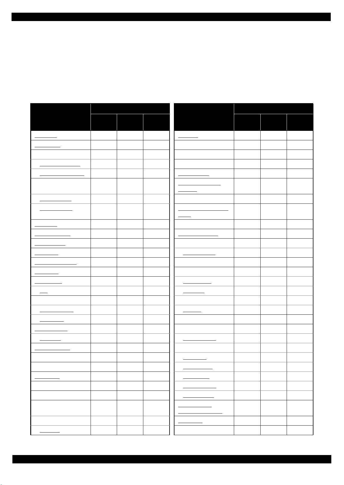
Revision Status
Revision Date of Issue Description
A October 8, 2010 First Release
Confidential
Page 7

L200/L201/L100/L101 Revision A
Contents
Chapter 1 Disassembly/Reassembly
1.1 Overview ................................................................................................................................................................... 9
1.1.1 Tools ................................................................................................................................................................. 9
1.1.2 Checks and precautions before disassembling ............................................................................................... 10
1.1.3 Protection for Transportation.......................................................................................................................... 12
1.2 Disassembly/Reassembly Procedures ..................................................................................................................... 14
1.2.1 Standard Operation Time for servicing the product ....................................................................................... 15
1.2.2 Disassembling/Reassembling Flowchart........................................................................................................ 18
1.2.2.1 Housing Part .......................................................................................................................................... 18
1.2.2.2 Printer Mechanism Part ......................................................................................................................... 20
1.3 Details of Disassembling/Reassembling by Parts/Unit........................................................................................... 23
1.4 Routing FFCs/cables ............................................................................................................................................... 31
Chapter 2 Adjustment
2.1 Required Adjustments ............................................................................................................................................. 34
2.2 Details of Adjustments ............................................................................................................................................ 36
2.2.1 TOP Margin Adjustment ................................................................................................................................ 36
Chapter 3 Maintenance
3.1 Overview ................................................................................................................................................................. 38
3.1.1 Cleaning .......................................................................................................................................................... 38
3.1.2 Lubrication...................................................................................................................................................... 38
3.2 Lubrication Points and Instructions......................................................................................................................... 39
Chapter 4 Appendix
4.1 Power-On Sequence ................................................................................................................................................ 42
4.2 Connector Diagram ................................................................................................................................................. 44
4.3 Troubleshooting....................................................................................................................................................... 45
4.3.1 Troubleshooting Workflow ............................................................................................................................ 45
4.3.2 Fatal Error Code ............................................................................................................................................. 47
7
Confidential
Page 8

CHAPTER 1
DISASSEMBLY/REASSEMBLY
Confidential
Page 9
L200/L201/L100/L101 Revision A
1.1 Overview
This chapter describes procedures for disassembling the main parts/units of L200/L201/L100/L101. Unless
otherwise specified, disassembled parts/units can be reassembled by reversing the disassembly procedure. See
the cautions or tips for disassembly/reassembly described in “ 1.3 Details of Disassembling/Reassembling by
Parts/Unit (p23)”.
Read the following before disassembling and reassembling.
“ Safety Precautions (p3)”
“ 1.1.2 Checks and precautions before disassembling (p10)”
When you have to remove units or parts that are not described in this chapter, see the exploded diagrams of SPI
(Service Parts Information).
1.1.1 Tools
Use only specified tools to avoid damaging the printer.
Table 1-1. Tools
Name EPSON Part Code*
(+) Phillips screwdriver #1 1080530
(+) Phillips screwdriver #2 ---
Flathead screwdriver ---
Flathead Precision screwdriver #1 ---
Tweezers ---
Longnose pliers ---
Acetate tape 1003963
Nippers ---
Note *: All of the tools listed above are commercially available.
EPSON provides the tools listed with EPSON part code.
Disassembly/Reassembly Overview 9
Confidential
Page 10
L200/L201/L100/L101 Revision A
Ink Tube Guide 1st
A
C
B
Joint
Ink Supply Tank Assy
Valve Assy
Tube Assy
Adapter Assy
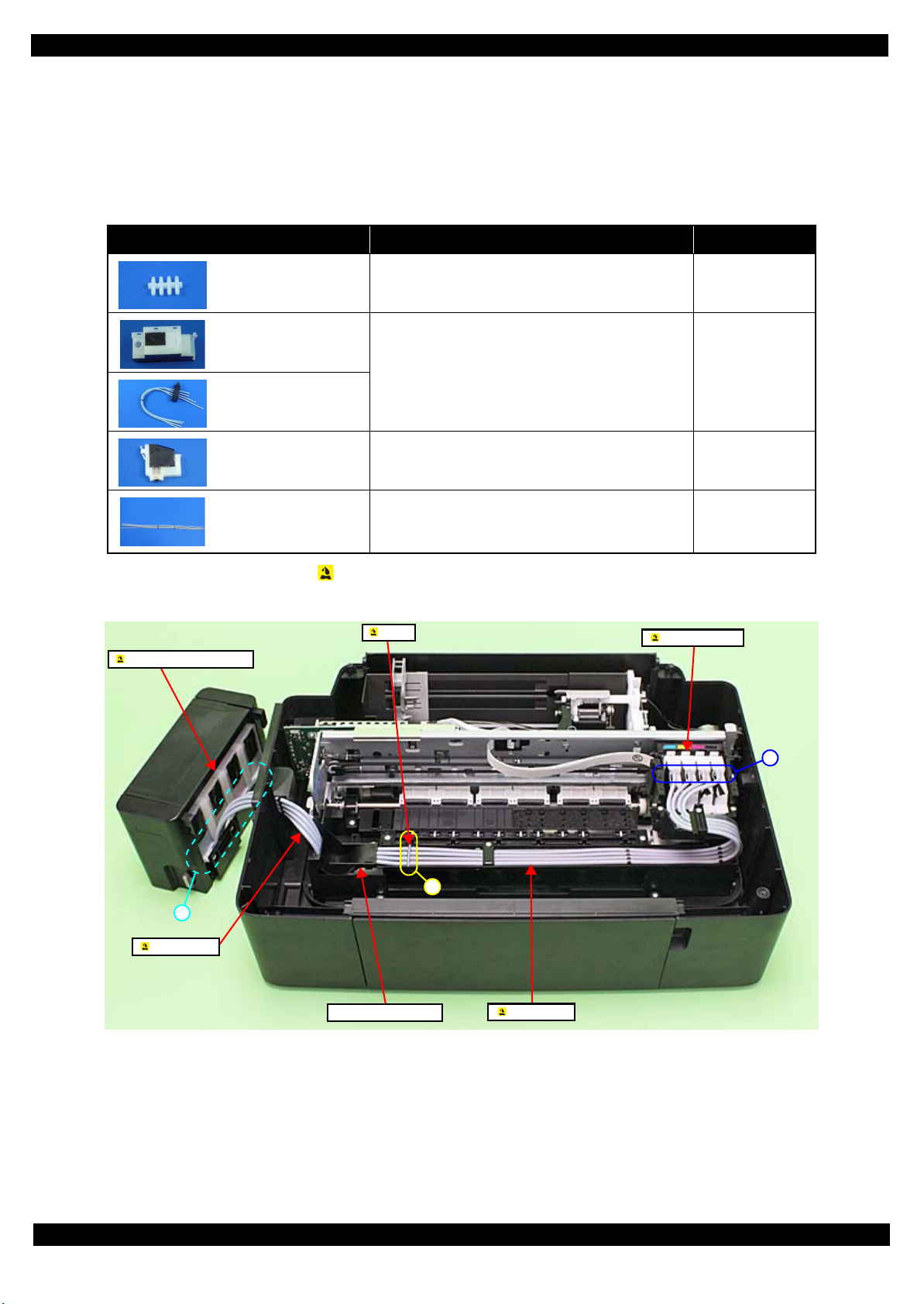
1.1.2 Checks and precautions before disassembling
Ink may spill when removing the following parts from L200/L201/L100/L101.
This section describes the parts that may cause ink spill and the means to minimize the ink spill when removing
the parts.
The parts that may cause ink spill when removing
Parts When ink may spill Location
Joint Removing the tubes of the Valve Assy / Tube Assy
from the Joint
Ink Supply Tank Assy Removing the tubes of the Valve Assy from the Joint
Removing the tubes of the Valve Assy from the Ink
Supply Tank Assy
Valve Assy
Adapter Assy Removing the Tube Assy from the Adapter Assy
A
A, B
C
Tube Assy Removing the tubes of the Valve Assy / Tube Assy
from the Joint
Removing the Tube Assy from the Adapter Assy
Note : These parts are indicated with the icon in disassembly/reassembly flowchart. (See “ 1.2 Disassembly/Reassembly Procedures
(p14)”.)
A, C
Figure 1-1. Location
Disassembly/Reassembly Overview 10
Confidential
Page 11
L200/L201/L100/L101 Revision A
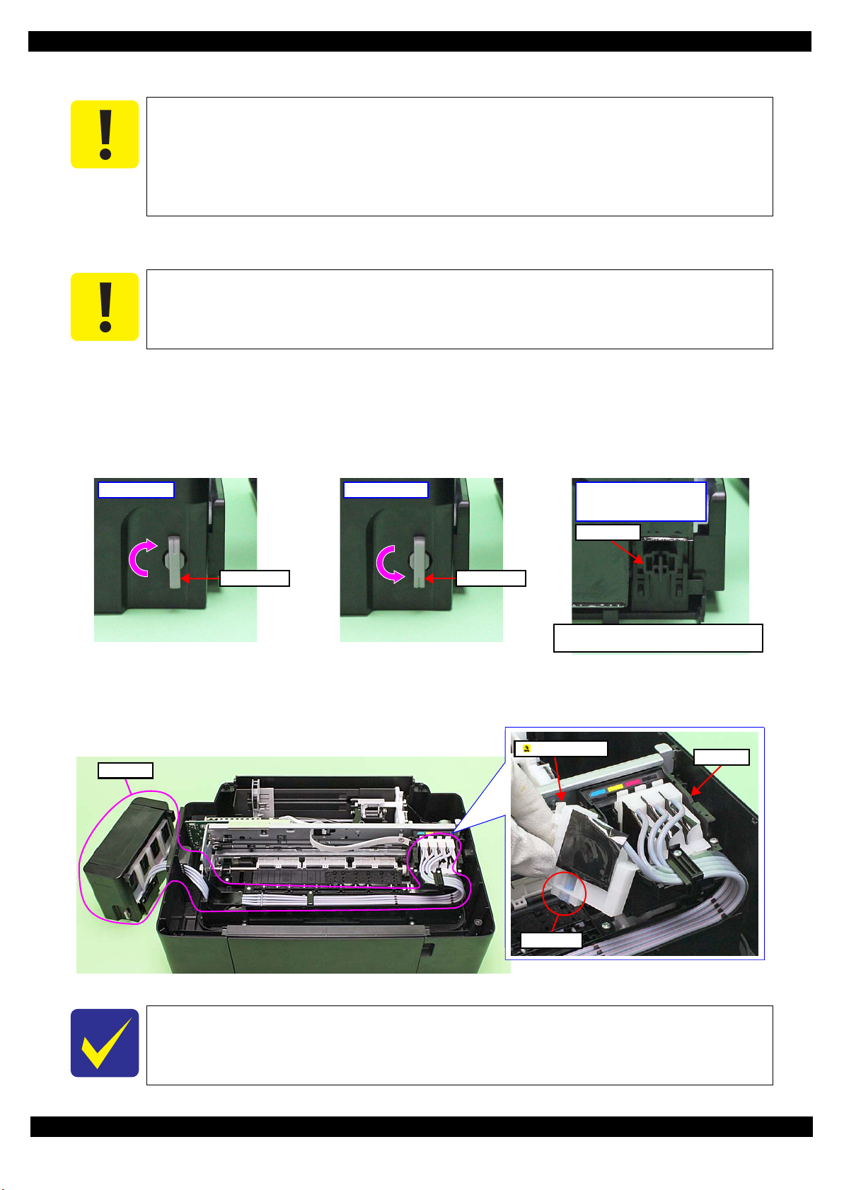
Valve LeverValve Lever
Open position Choke position
Choke Valve shaft is secured more tightly
in Choke position than in Open position.
Choke position
(When checking with the
Valve Lever removed.)
Valve shaft
Ink path
Carriage
Ink valve
Adapter Assy
Means do to minimize the ink spill
Even observing the points described in this section, ink may spill in the following situations.
Therefore, be careful not to contaminate the inside of the printer or its surroundings by
preparing the container to receive the leaked ink, or the like.
When removing the Valve Assy, some ink will spill from both ends of the ink tube even
the Valve Lever is closed.
When removing the Tube Assy, all the ink in the ink tube will spill.
Before disassembling, confirm that the printer is in the following condition.
Choke Valve is closed
Do not turn the Valve Lever too much when closing the Choke Valve, otherwise, the Valve
Lever and/or Valve Assy may get damaged.
• Before disassembling:
Turn the Valve Lever and be sure to close the Choke Valve.
• After reassembling is complete:
Open the Choke Valve to perform the print inspection.
• Before returning the printer to the user after repairing:
Make sure to turn the Valve Lever up to the choke position to close the Choke Valve before packing the printer.
Figure 1-2. Opening/closing the Choke Valve
Adapter Assy is removed
Before disconnecting the joint parts of the ink path, make sure that the Adapter Assy is removed from the Carriage.
The Adapter Assy has an ink valve which cuts off the ink path when removing the Adapter
Assy from the carriage.
Figure 1-3. Adapter Assy
Disassembly/Reassembly Overview 11
Confidential
Page 12
L200/L201/L100/L101 Revision A
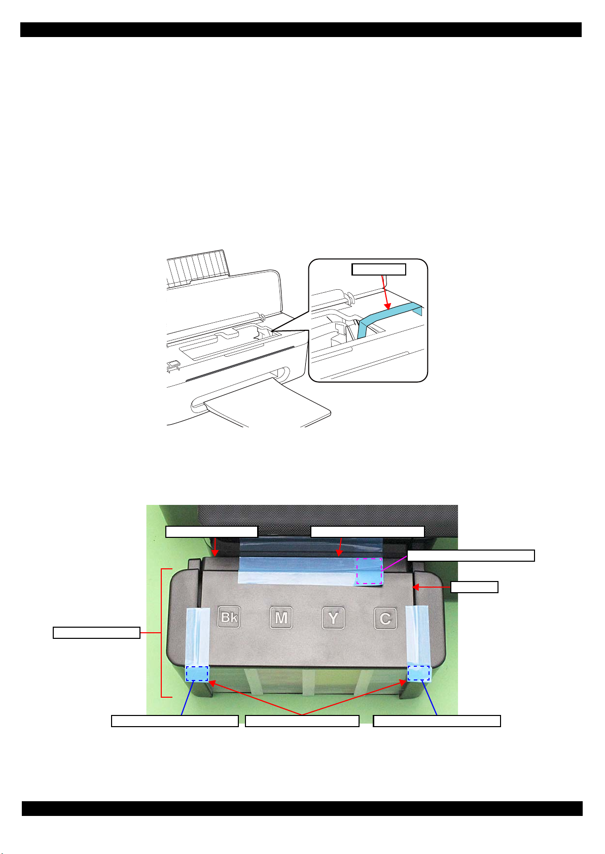
Strong tape
Top Cover
Ink Supply Tank Assy
Strong tape (22 mm x 55 mm)
Strong tape (22 mm x 105 mm)Ink Supply Holder Assy
Fold over the tape edge by 15 mm
Fold over the tape edge by 10 mm Fold over the tape edge by 10 mm
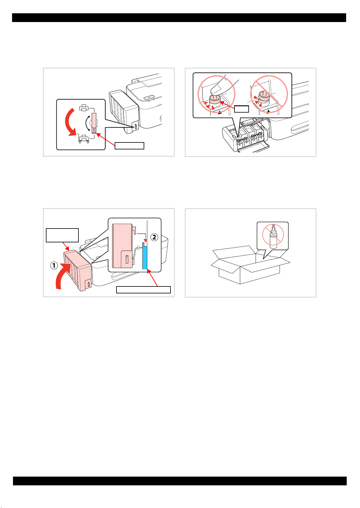
1.1.3 Protection for Transportation
Before packing the printer for returning it to the user, secure it at the specified points with strong tape to avoid
damaging the printer or ink leakage during transport, and make sure to check the points as follows.
Securing each parts
Secure the following parts with strong tape (width: 22 mm).
Securing the Carriage Assy
1. Cofirm that the Carriage Assy is locked in the home position.
2. Attach the unfolded end of strong tape (fold the other end back 5 mm) on the bottom left of the CR
Cover.
3. Pull the tape to the right side of the housing and attach it tightly.
Figure 1-4. Securing the Carriage Assy
Securing the Ink Tank
• Secure both sides of the Top Cover with strong tape (x2).
• Secure the Ink Supply Tank Assy and Ink Supply Holder Assy with strong tape (x1).
Figure 1-5. Securing the Ink Supply Tank Assy
Disassembly/Reassembly Overview 12
Confidential
Page 13
L200/L201/L100/L101 Revision A
Valve Lever
Cap
Ink Supply
Tank Assy
Ink Supply Holder Assy
Points to be checked before packing the printer
The Valve Lever is on the position shown below
(the Choke Valve is closed). (See Figure 1-2.)
All the caps of the Ink Supply Tank Assy are
securely closed.
The hooks (x2) of the Ink Supply Tank Assy are
securely engaged with the Ink Supply Holder Assy.
The opened ink bottle is not included in the box.
Disassembly/Reassembly Overview 13
Confidential
Page 14

L200/L201/L100/L101 Revision A
Main Frame
4
5
(p 24) (p 39)
EJ Roller Gear
---
---
---
Item Description Reference
Parts/unit name
White-letter
Parts/units supplied as an ASP ---
Black-letter
Parts/units not supplied as an ASP ---
Icon
Indicates a practice or condition that could result in
injury or loss of life if not strictly observed.
Indicates the reference
page in blue-letter
Indicates a practice or condition that could result in
damage to, or destruction of equipment if not strictly
observed.
Indicates the reference
page in blue-letter
Indicates the parts that are inevitably broken in the
disassembling procedure, and should be replaced with
a new one for reassembly.
---
Indicates the parts that may cause the ink spill when
they are removed.
“ 1.1.2 Checks and
precautions before
disassembling (p10)”
Indicates necessary check items in the disassembling/
reassembling procedure.
Indicates the reference
page in blue-letter
Indicates supplementary explanation for disassembly
is given.
Indicates the reference
page in blue-letter
Indicates particular tasks to keep quality of the units
are required.
Indicates the reference
page in blue-letter
Indicates particular routing of cables is required.
Indicates the reference
page in blue-letter
Indicates particular adjustment(s) is/are required.
Chapter 2 “ Adjustment
(p33)”
Indicates lubrication is required.
Chapter 3 “ Maintenance
(p37)”
Indicates the number of screws securing the parts/
units.
---
Indicates the points secured with other than a screw
such as a hook, rib, dowel or the like.
---
White letters indicate a
part/unit supplied as an
ASP.
Black letters indicate a
part/unit not supplied as
an ASP.
Shows the screw types
and the specified torque
in the “Screw type/torque
list”.
Tube Assy
---
---
(p 28)
Shows removal/
installation as a unit/assy.
is available.
Reference page
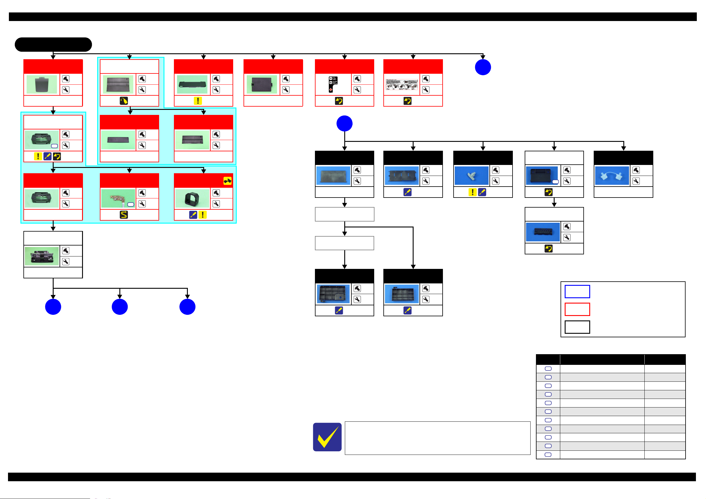
1.2 Disassembly/Reassembly Procedures
This section describes procedures for disassembling the parts/units in a flowchart format. For some parts/units,
detailed procedures or precautions are provided (accordingly indicated by icons and cell's color). Refer to the
explanations in the example chart below and perform an appropriate disassembling and reassembling procedure.
(See“ 1.3 Details of Disassembling/Reassembling by Parts/Unit (p23)”.)
For routing cables, see “ 1.4 Routing FFCs/cables (p31)”
The example below shows how to see the charts on the following pages.
S1 S5
Disassembly/Reassembly Disassembly/Reassembly Procedures 14
Confidential
Page 15
L200/L201/L100/L101 Revision A
1.2.1 Standard Operation Time for servicing the product
The following are the standard operation time for servicing the product. Those are based on the MTTR result
measured using a prototype.
The underlined parts/units are supplied as After Service Parts.
Standard Operation Time for servicing L200/L201: See Table 1-2.
Standard Operation Time for servicing L100/L101: See Table 1-3.
Table 1-2. Standard Operation Time (L200/L201)
Time (second)
Parts/Unit
Panel Unit
Panel Board
Paper Support Assy 12 0 12 EJ Frame Assy 149 0 149
Paper Support Tray
Paper Support Tray 2
Stacker Assy
Tray Exit Inner
Tray Exit Outer
Jam Cover 17 0 17 CR Motor 235 406 641
Document Cover 9 0 9 Power Supply Unit 129 406 535
Document Pad
ASF Cover
Ink Cartridge Cover
Rear Cover
Scanner Unit
CIS
Middle Housing Assy 674 0 674 Timing Belt 915 406 1321
Middle Housing
USB Cover
LD Roller Assy
LD Roller
Housing Buckler
Roller Idler Pick Assy 160 0 160 Gear Pump
CR Scale 181 0 181 Bracket Pump
Main Board
Driven Pulley Assy 363 0 363 Waste Ink Tube
Pick Assy 376 0 376 Pump Housing
Cap Unit
Lever Cleaner 175 0 175 PF Encoder
Cap Assy
Replace-
ment
14014Printhead 364 1642 2006
29 0 29 Holder Contact 293 0 293
20 0 20 EJ Roller 170 406 576
26026EJ Roller Gear 134 0 134
12012
15 0 15 Cover Flashing 195 0 195
18018
20 0 20 Waste Ink Tray Assy 163 35 198
5 0 5 Waste Ink Pads 239 35 274
18 0 18 Main Frame 501 406 907
10 0 10 Carriage Assy 906 406 1312
228 0 228 PCB Encoder 953 406 1359
245 0 245 Head FFC 939 406 1345
146 0 146 Carriage 995 406 1401
146 0 146 Upper Paper Guide 269 0 269
186 406 592 Pump Assy 791 0 791
227 406 633 Gear Pump Idle 797 0 797
183 0 183 Lever Pick Clutch 798 0 798
150 535 685 Roller Pump 827 0 827
405 0 405
449 0 449 PF Scale 170 0 170
Adjust-
ment
Total
Parts/Unit
Waste Ink Pads (for
flushing)
Porous Pad Front Paper
Guide
Waste Ink Pads
(under the Cap Assy)
Replace-
Time (second)
Adjust-
ment
230 0 230
159 0 159
811 0 811
832 0 832
892 0 892
892 0 892
409 0 409
148 0 148
ment
Total
Disassembly/Reassembly Disassembly/Reassembly Procedures 15
Confidential
Page 16

L200/L201/L100/L101 Revision A
Table 1-2. Standard Operation Time (L200/L201)
Time (second)
Parts/Unit
PF Roller 579 0 579 Left Cover 44044
PF Motor 531 0 531 Ink Supply Tank Assy
Ink Tube Guide 1st
Tube Pressing Plate 274 0 274 Cap
Ink Supply Holder Assy
CR Cover 746 0 746 Tube Guide Plate
Tube Holder Top /
Tube Holder Lower
Adapter Assy
CR Front 522 0 522 FFC Cover 461 0 461
Top Cover
Bottom Cover
Valve Lever
Right Cover
Replace-
ment
278 0 278 Ink Tube Guide 2nd 698 0 698
613 0 613 Joint 449 0 449
741 0 741
488 0 488 Tube Assy 677 0 677
909Valve Assy 1473 0 1473
16016
15015
49049
Adjust-
ment
Total
Parts/Unit
Tube Guide Plate
Support
Replace-
Time (second)
Adjust-
ment
866 0 866
606
515 0 515
545 0 545
ment
Total
Table 1-3. Standard Operation Time (L100/L101)
Time (second)
Parts/Unit
Printer Cover
Panel Board
Paper Support Assy 9 0 9 EJ Roller 111 406 517
Paper Support Tray
Paper Support Tray 2
Stacker Assy 3 0 3 Cover Flushing 136 0 136
Rear Cover
Upper Housing Assy 144 0 144 CR Motor 176 406 582
Upper Housing 87 0 87 Power Supply Unit 70 406 476
USB Cover
LD Roller Assy
LD Roller
Housing Buckler
Roller Idler Pick Assy 101 0 101 PCB Encoder
CR Scale 122 0 122 Head FFC
Main Board
Cap Unit 346 0 346 Carriage
Lever Cleaner 116 0 116 PF Encoder
Cap Assy
Driven Pulley Assy 304 0 304 Adapter Assy
Replace-
ment
10 0 10 Holder Contact 234 0 234
204 0 204 EJ Frame Assy 90 0 90
17017EJ Roller Gear 75075
23023
10010
87 0 87 Waste Ink Tray Assy 104 35 139
127 406 533 Waste Ink Pads 180 35 215
168 406 574 Main Frame 442 406 848
124 0 124 Carriage Assy 847 406 1253
91 535 626 Timing Belt 856 406 1262
390 0 390 PF Scale 111 0 111
Adjust-
ment
Total
Parts/Unit
Waste Ink Pads
(for flushing)
Porous Pad Front Paper
Guide
Replace-
Time (second)
Adjust-
ment
171 0 171
100 0 100
894 406 1300
880 406 1286
936 406 1342
89089
389 0 389
ment
Total
Disassembly/Reassembly Disassembly/Reassembly Procedures 16
Confidential
Page 17

L200/L201/L100/L101 Revision A
Table 1-3. Standard Operation Time (L100/L101)
Time (second)
Parts/Unit
Pick Assy 317 0 317 CR Front 389 0 389
Waste Ink Pads
(under the Cap Assy)
Pump Assy 732 0 732 Bottom Cover
Gear Pump Idle
Lever Pick Clutch 739 0 739 Right Cover
Gear Pump
Bracket Pump
Roller Pump
Waste Ink Tube
Pump Housing
Upper Paper Guide 195 0 195 Tube Guide Plate
PF Roller 476 0 476
PF Motor 472 0 472 Tube Assy 520 0 520
Printhead
Ink Tube Guide 1st
Tube Pressing Plate 190 0 190
Ink Supply Holder Assy
CR Cover 216 0 216
Tube Holder Top /
Tube Holder Lower
Replace-
ment
350 0 350
738 0 738 Valve Lever 15015
752 0 752 Left Cover 44044
773 0 773 Ink Supply Tank Assy 778 0 778
768 0 768 Ink Tube Guide 2nd 376 0 376
833 0 833 Cap 606
833 0 833 Joint 365 0 365
305 1642 1947 FFC Cover 377 0 377
194 0 194 Valve Assy 747 0 747
352 0 352
211 0 211
Adjust-
ment
Total
Parts/Unit
Top Cover
Tube Guide Plate
Support
Replace-
Time (second)
Adjust-
ment
909
16016
49049
431 0 431
461 0 461
ment
Total
Disassembly/Reassembly Disassembly/Reassembly Procedures 17
Confidential
Page 18

L200/L201/L100/L101 Revision A
1.2.2 Disassembling/Reassembling Flowchart
1.2.2.1 Housing Part
L200/L201 START
Panel Unit
Jam Cover
Scanner Unit
S2
(p 23) (p 31)
Ink Tube Guide
1st
S9
(p 29) (p 27)
Jam Cover
(p 25)
Stacker Assy
---
2
---
---
2
Ink Cartridge
Cover
---
---
2
CIS
Tra y E xit I n n e r
---
---
4
---
2
---
Joint
1
---
2
(p 28)
4
4
(p 31) (p 39)
S2
(p 23)
Tube Pressing
Plate
1
2
S9
---
Tra y E xit O u ter
---
Tube Guide Plate
Support
(p 29)
---
2
---
---
Paper Support
Assy
(p 39)
Paper Support
Tra y
---
ASF Cover
---
2
---
---
2
Paper Support
Tray 2
---
2
---
---
2
Panel Unit
(p 23)
Panel Board
S1
---
Valve Positio n
Label
(p 29)
Document Cover
---
4
---
---
2
Rear Cover
---
1
---
Document Pad
1
---
(p 23)
Refilling Ink
Label
---
---
(p 29)
---
---
---
---
D
(p 19)
Ink Supply
Holder Assy
S10
(p 29) (p 29)
Middle Housing
Assy
S2
---
Printer
Mechanism
---
A
---
---
2
2
L200/L201 specific parts/unit
L100/L101 specific parts/unit
Common parts/unit
4
4
Screw type/torque list
Symbol Screw type Torque
S1
C.B.P-TITE SCREW 3x8 5.0 ± 0.5 kgf·cm
Middle
Housing
(p 29)
B
(p 21)(p 20)
USB Cover
---
---
(p 25)
---
2
See “ Flowchart 1-2 Disassembling Flowchart of Housing Part (2)
(p19)” for disassembly of the Housing Part of L100/L101.
C
(p 22)
S2
C.B.P-TITE SCREW 3x10 5.0 ± 0.5 kgf·cm
S3
C.B.S-TITE SCREW 3x5 7.5
S4
C.B.P-TITE SCREW 2.6x8 4.0 ± 0.25 kgf·cm
S5
C.P.(P1) SCREW 2.6x3.5 3.5
S6
C.B.S-TITE SCREW 2x5 3.5 ± 0.25 kgf·cm
S7
C.B.P-TITE SCREW 2x6 3.0
S8
C.F.B-TITE SCREW 2.6x6 3.0 ± 0.25 kgf·cm
S9
C.B.P TITE SCREW 2.5x5 5.0 ~ 6.0 kgf·cm
S10
C.B.P TITE SCREW 3x6 5.0 ~ 6.0 kgf·cm
S11
C.B.P TITE SCREW 2.6x16 5.0 ~ 6.0 kgf·cm
± 0.5 kgf·cm
± 0.25 kgf·cm
± 0.25 kgf·cm
Flowchart 1-1. Disassembling Flowchart of Housing Part (1)
Disassembly/Assembly Disassembling/Assembling Flowchart 18
Confidential
Page 19
L200/L201/L100/L101 Revision A
L100/L101 START
Stack er
---
Upper Housing
Assy
S2
(p 30)
Upper Housing
---
Printer
Mechanism
---
---
---
---
Paper Support
Assy
---
2
(p 40)
Paper Support
Tra y
4
8
---
2
---
2
Panel Board
2
S1
(p 32)
---
Printer Cover
(p 30)
Paper Support
Tra y 2
---
USB Cover
(p 25)
Rear Cover
---
2
---
---
1
---
2
---
2
Valve Positio n
Label
(p 29)
L200/L201: (p 18)
D
L100/L101: (p 19)
Top Cover
---
Bottom Cover
---
---
---
Refilling Ink
Label
---
D
(p 19)
---
(p 30)
Bottom Cover
---
2
(p 27)
4
Valve L e v e r
---
2
(p 26)
Tube Valve Holder
Rear
S10
(p 28)
Tube Valve Holder
Front
Cap
2
2
---
---
---
---
2
Valv e L e v e r
(p 28)
A
---
---
B
(p 21)(p 20)
C
(p 22)
Right Cover
(p 27)
---
Left Cover
---
7
(p 27)
7
L200/L201 specific parts/unit
L100/L101 specific parts/unit
Common parts/unit
Screw type/torque list
Symbol Screw type Torque
S1
C.B.P-TITE SCREW 3x8 5.0 ± 0.5 kgf·cm
S2
C.B.P-TITE SCREW 3x10 5.0 ± 0.5 kgf·cm
S3
See “ Flowchart 1-1 Disassembling Flowchart of Housing Part (1)
(p18)” for disassembly of the Housing Part of L200/L201.
C.B.S-TITE SCREW 3x5 7.5
S4
C.B.P-TITE SCREW 2.6x8 4.0 ± 0.25 kgf·cm
S5
C.P.(P1) SCREW 2.6x3.5 3.5
S6
C.B.S-TITE SCREW 2x5 3.5 ± 0.25 kgf·cm
S7
C.B.P-TITE SCREW 2x6 3.0
S8
C.F.B-TITE SCREW 2.6x6 3.0 ± 0.25 kgf·cm
S9
C.B.P TITE SCREW 2.5x5 5.0 ~ 6.0 kgf·cm
S10
C.B.P TITE SCREW 3x6 5.0 ~ 6.0 kgf·cm
S11
C.B.P TITE SCREW 2.6x16 5.0 ~ 6.0 kgf·cm
± 0.5 kgf·cm
± 0.25 kgf·cm
± 0.25 kgf·cm
Flowchart 1-2. Disassembling Flowchart of Housing Part (2)
Disassembly/Assembly Disassembling/Assembling Flowchart 19
Confidential
Page 20

L200/L201/L100/L101 Revision A
1.2.2.2 Printer Mechanism Part
L200/L201: (p 18)
A
L100/L101: (p 19)
LD Roller Assy
(p 25) (p 40)
(p 34)
Main Board
CR Scale
Pick Assy
S1
(p 31)
CR Cover
LD Roller
---
2
S1
S8
(p 25)
2
---
PF Encoder
S6
(p 34)
1
---
PF Scale
---
---
Driven Pulley
(p 34)
Lever Cleaner
---
---
---
Cap Unit
---
2
(p 24) (p 34)
CR Scale
(p 24) (p 34)
Cap Assy
---
Main Board
---
2
S3
(p 23)
(p 31) (p 34)
Upper Paper
Guide
---
3
(p 34)
2
3
---
6
Main Board
S3
(p 23) (p 31)
2
3
EJ Roller Gear
---
---
---
Housing
Buckler
---
1
(p 25)
Assy
2
---
(p 40)
---
Waste Ink Pads
---
(under the Cap Assy)
---
---
---
Screw
Tube Holder Top/
Tube Holder
Lower
Adapter Assy
Main Frame
S1 S3
(p 24) (p 39)
(p 34)
Lever Cleaner
Cap Unit
Pump Assy
(p 26)
L200/L201 specific parts/unit
Ink Tube Guide
L100/L101 specific parts/unit
2nd
4
5
1
(p 22)
EJ Frame Assy
Common parts/unit
Screw type/torque list
EJ Roller Gear
PF Motor
EJ Roller
3
S1 S5
(p 32) (p 34)
---
Cover Flashing
PF Roller
---
2
2
(p 21)
(p 40) (p 34)
---
---
Symbol Screw type Torque
S1
C.B.P-TITE SCREW 3x8 5.0 ± 0.5 kgf·cm
S2
C.B.P-TITE SCREW 3x10 5.0 ± 0.5 kgf·cm
S3
C.B.S-TITE SCREW 3x5 7.5
S4
C.B.P-TITE SCREW 2.6x8 4.0 ± 0.25 kgf·cm
S5
C.P.(P1) SCREW 2.6x3.5 3.5
S6
C.B.S-TITE SCREW 2x5 3.5 ± 0.25 kgf·cm
S7
C.B.P-TITE SCREW 2x6 3.0
S8
C.F.B-TITE SCREW 2.6x6 3.0 ± 0.25 kgf·cm
S9
C.B.P TITE SCREW 2.5x5 5.0 ~ 6.0 kgf·cm
S10
C.B.P TITE SCREW 3x6 5.0 ~ 6.0 kgf·cm
S11
C.B.P TITE SCREW 2.6x16 5.0 ~ 6.0 kgf·cm
± 0.5 kgf·cm
± 0.25 kgf·cm
± 0.25 kgf·cm
Flowchart 1-3. Disassembling Flowchart of Printer Mechanism Part (1)
Disassembly/Assembly Disassembling/Assembling Flowchart 20
Confidential
Page 21

L200/L201/L100/L101 Revision A
L200/L201: (p 18)
B
L100/L101: (p 19)
CR Cover
S9
(p 27)
Screw
Tube Holder Top/
Tube Holder
Lower
Adapter Assy
(p 28)
Porous Pad Front
Paper Guide
2
2
(p 25)
Tube Pressing
Plate
---
---
Waste Ink Tray
Assy
S1
(p 26)
Waste In k Pa ds
(p 34)
Screw
2
---
S11
(p 28)
---
---
Tube Holder Top/
Tube Holder
Lower
---
6
(p 28)
---
5
Roller Idler Pick
Assy
(p 40)
Power Supply
Unit
---
---
S1
(p 24) (p 34)
2
1
---
(p 20)
Gear Pump Idle
---
CR Motor
S5
(p 31) (p 34)
Lever Pick Clutch
2
---
---
Tube Pressing
Plate
S9
---
Joint
1
---
(p 28)
---
2
Tube Guide Plate
Support
(p 29)
---
---
Tube Gui d e P l a t e
1
---
1
---
---
(p 26)
(p 26)
4
---
Gear Pump
Holder Contact
---
FFC Cover
Printhead
S4
(p 31) (p 34)
FFC Cover
CR Front
Tube Assy
---
---
---
---
(p 24)
---
3
S9
(p 27)
2
2
(p 28) (p 34)
---
---
(p 26)
L200/L201 specific parts/unit
Bracket Pump
---
---
(p 26)
Roller Pump
(p 26)
---
---
L100/L101 specific parts/unit
Common parts/unit
Screw type/torque list
3
---
Waste Ink Tube
(p 26)
Pump Housing
(p 26)
Symbol Screw type Torque
---
---
---
---
S1
C.B.P-TITE SCREW 3x8 5.0 ± 0.5 kgf·cm
S2
C.B.P-TITE SCREW 3x10 5.0 ± 0.5 kgf·cm
S3
C.B.S-TITE SCREW 3x5 7.5
S4
C.B.P-TITE SCREW 2.6x8 4.0 ± 0.25 kgf·cm
S5
C.P.(P1) SCREW 2.6x3.5 3.5
S6
C.B.S-TITE SCREW 2x5 3.5 ± 0.25 kgf·cm
S7
C.B.P-TITE SCREW 2x6 3.0
S8
C.F.B-TITE SCREW 2.6x6 3.0 ± 0.25 kgf·cm
S9
C.B.P TITE SCREW 2.5x5 5.0 ~ 6.0 kgf·cm
S10
C.B.P TITE SCREW 3x6 5.0 ~ 6.0 kgf·cm
S11
C.B.P TITE SCREW 2.6x16 5.0 ~ 6.0 kgf·cm
± 0.5 kgf·cm
± 0.25 kgf·cm
± 0.25 kgf·cm
Flowchart 1-4. Disassembling Flowchart of Printer Mechanism Part (2)
Disassembly/Assembly Disassembling/Assembling Flowchart 21
Confidential
Page 22

L200/L201/L100/L101 Revision A
L200/L201: (p 18)
C
L100/L101: (p 19)
(p 20)
1
Ink Tube Guide
1st
S9
(p 30) (p 27)
Ink Supply
Holder Assy
S10
(p 30) (p 30)
Tube Pressing
Plate
Ink Tube Guide
2nd
1
2
S2
(p 27)
2
2
Top Co ver
Bottom Cover
CR Motor
Holder Contact
CR Front
EJ Frame Assy
Valv e L e v e r
FFC Cover
2
4
(p 27)
---
---
Right Cover Left Cover
Printhead
Carriage Assy
EJ Roller Gear
Tube Valve Holder
Rear
---
---
EJ Roller
Tube Valve Holder
Front
(p 34)
---
PCB Encoder
Head FFC
Timing Belt
---
(p 39) (p 34)
Cover Flushing
S1
---
---
Valve Assy
---
2
1
(p 28)
S7
---
2
---
(p 32)
---
---
---
Carriage
Cap
---
---
---
L200/L201 specific parts/unit
L100/L101 specific parts/unit
---
Common parts/unit
Waste Ink Pads
(for flushing)
---
Ink Supply Tank
Assy
(p 25) (p 31)
---
Screw type/torque list
---
---
(p 26)
7
Symbol Screw type Torque
S1
C.B.P-TITE SCREW 3x8 5.0 ± 0.5 kgf·cm
S2
C.B.P-TITE SCREW 3x10 5.0 ± 0.5 kgf·cm
S3
C.B.S-TITE SCREW 3x5 7.5
S4
C.B.P-TITE SCREW 2.6x8 4.0 ± 0.25 kgf·cm
S5
C.P.(P1) SCREW 2.6x3.5 3.5
S6
C.B.S-TITE SCREW 2x5 3.5 ± 0.25 kgf·cm
S7
C.B.P-TITE SCREW 2x6 3.0
S8
C.F.B-TITE SCREW 2.6x6 3.0 ± 0.25 kgf·cm
S9
C.B.P TITE SCREW 2.5x5 5.0 ~ 6.0 kgf·cm
S10
C.B.P TITE SCREW 3x6 5.0 ~ 6.0 kgf·cm
S11
C.B.P TITE SCREW 2.6x16 5.0 ~ 6.0 kgf·cm
± 0.5 kgf·cm
± 0.25 kgf·cm
± 0.25 kgf·cm
Flowchart 1-5. Disassembling Flowchart of Printer Mechanism Part (3)
Disassembly/Assembly Disassembling/Assembling Flowchart 22
Confidential
Page 23
L200/L201/L100/L101 Revision A
Panel Unit
Panel FFC
Standard line
Double-sided tape
Document Cover
Document Pad
Origin Position
3
Panel FFC
Scanner FFC
Scanner Motor cable
Scanner
Unit
Scanner Unit
1
2
4
C.B.P-TITE SCREW 3x10 (5.0 ± 0.5 kgf·cm)
Spacer
Backside of the CIS
Timing Belt
Torsion Spring
Toothed
side
CIS
C.B.S-TITE SCREW 3x5 (7.5 ± 0.5 kgf·cm)
C.B.P-TITE SCREW 3x8 (5.0 ± 0.5 kgf·cm)
Main Board
PE Sensor Lever
Rib
Main Board
Grounding wire Plate of PF Motor
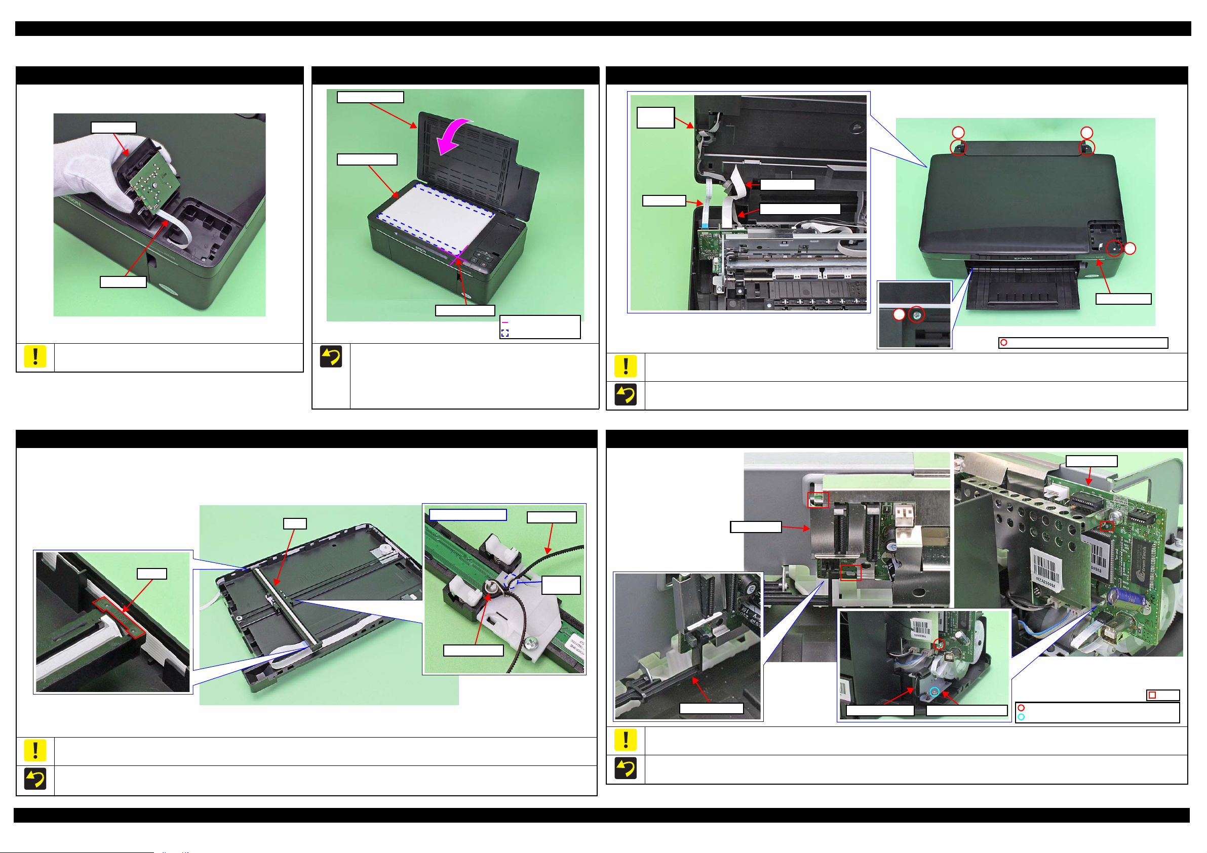
1.3 Details of Disassembling/Reassembling by Parts/Unit
Panel Unit (L200/L201)
Do not lift the Panel Unit too fast, since the Panel FFC is connected
to the back of the Panel Unit.
Document Pad (L200/L201)
When installing the Document Pad, follow the procedure below.
1. Place the Document Pad with the side where the double-sided
tape attached upward on the document glass aligning its corner
with the origin position.
2. Close the Document Cover to attach the Document Pad.
Scanner Unit (L200/L201)
Do not lift the Scanner Unit too fast, since the Panel FFC, Scanner Motor cable and Scanner FFC are connected to the rear side of the Scanner Unit.
Tighten the screws in the order indicated in the figure above.
CIS (L200/L201)
Be careful not to lose the Spacer because it comes off easily when disassembling the CIS.
When installing the spacers, be sure to place them with the cutout facing inward.
Align the toothed side of the Timing Belt with the same shaped rib of the backside of the CIS, and secure the Timing Belt with Torsion Spring.
Disassembly/Assembly Details of Disassembling/Reassembling by Parts/Unit 23
Take care not to damage the PE Sensor Lever.
Align the ribs (x3) of the Main Frame with the cutouts of the Main Board.
Screw one side of the grounding wire (w/ ferrite core) together with the plate of the PF Motor, and the other side together with the Main Board.
Main Board
Confidential
Page 24

L200/L201/L100/L101 Revision A
Power Supply Unit Power Supply Unit
Hole
Power Supply Unit Cable
FFC Cover
Head FFC
Groove
FFC Cover
Groove
Head FFC
Cleaner Lever Spring
Dowel Hole
Lever Cleaner
Protrusion
Waste Ink Tube
Point A
Cleaner Case Spring
Hook
Cleaner Case Spring
Cap Unit
Cap Unit
Dowel for temporarily secure
Frame Base
Step 1
Step 2
Step 3
Step 4
Hook
Hook
Grounding Spring
Hole
Bracket
Main
Frame
Lower part of 80-column side
TBD
1
Main Frame
2
3
4
Main FrameLeft Side Right Side
C.B.P-TITE SCREW 3x8 (5.0 ± 0.5 kgf·cm)
C.B.S-TITE SCREW 3x5 (7.5 ± 0.5 kgf·cm)
Cutout
Hole
Lower part of 0-column side
Extension Spring
CR Scale
Extension Spring
Power Supply Unit
Route the Power Supply Unit cable through the hole of the Frame
Base.
FFC Cover
Insert the folded part of the Head FFC into the groove of the FFC
Cover.
Cap Unit
When installing the Cap Unit, follow the instruction below.
1. Temporarily secure the Cleaner Case Spring to the hook and dowel of the Frame Base.
2. Insert the Waste Ink Tube to the Cap Unit until point A (p 26) is hidden.
3. Install the Cap Unit to the Frame Base, and attach the Cleaner Case Spring which is secured temporary earlier to the hook on the Cap Unit.
4. Insert one leg of the Cleaner Lever Spring to the hole of the Frame Base, and secure it to the dowel of the Frame Base, then secure the other leg
to the protrusion of the Lever Cleaner.
Main Frame
When installing the Grounding Spring of the lower part of the 80-digit side, follow the instruction below.
1. Insert the tip of the spring to the hole of the Frame Base.
Disassembly/Assembly Details of Disassembling/Reassembling by Parts/Unit 24
2. Attach the eye of the spring to the Bracket and secure the other eye to the hook on the Main Frame.
When installing the Extension Spring of the lower part of the 0-digit side, attach the tip of the Extension Spring to the hole of the Frame Base
first. Then attach the leg of the spring to the cutout of the Main Frame from the left side as seen from the rear of the printer.
Tighten the screws in the order indicated in the figure above.
When installing the CR Scale, confirm that the arrows on both
the edges of the CR Scale face upward.
When installing the Extension Spring, be sure to attach it with
its leg facing the rear of the printer.
CR Scale
Confidential
Page 25

L200/L201/L100/L101 Revision A
Pick Assy
Step 2, 3
Shaft Gear 24TConcave sectionBearing
C.B.P-TITE SCREW 3x8 (TBD)
C.F.B-TITE SCREW 3x5 (TBD)
Hook
Step 1
Gear 23T
Step 2
Shaft Gear 24T
LD Roller Assy
LD Roller
LD Roller Assy
Torsion Spring
Leg of the
spring
Friction Buckler R
Housing Bucklers Friction Buckler
Cutouts
Friction Buckler
Friction Buckler R
Friction Buckler
Sheet BF2-A
Double-sided
tape
Housing Buckler (Friction Buckler)
Housing Buckler (Friction Buckler R)
Grounding Plate
Guide Carriage
Compression Spring
Positioning Hole and Dowel
Hook
Protrusion
Compression Spring
Standard surface:
In the area with concaves and convexes on the
Porous Pad Front Paper Guide, use the level
of the concave section as a standard surface.
Rib
Protrusion
Jam Cover
Spring
Jam Cover
Hook
USB Cover
LD Roller Assy / LD Roller
When removing the LD Roller Assy, follow the procedure below.
1. Release the hooks (x2) and remove the Gear 23T.
2. Release the hooks (x2) and slide the Shaft Gear 24T to the 0-digit side until the concave section of the gear comes to the bearing part of the
Pick Assy.
3. Remove the LD Roller Assy upward.
When removing the LD Roller, remove the screws (x2) shown in the figure above.
When install the Torsion Spring, make sure to align the leg to the position as shown above.
Housing Buckler
When installing the Friction Buckler and Friction Buckler R to the Housing Buckler, pay attention to the following instructions.
• Remove the Sheet BF2-A on the rear side of the Friction Buckler to be replaced, and secure the removed sheet with double-sided tape to the
new Friction Buckler.
• Install the friction bucklers to the Housing Bucklers with the cutouts facing forward.
Install the buckler to the position as shown above.
Carriage
When replacing the Carriage, be careful about the following and
remove the Grounding Plate, Guide Carriage, Compression Springs
from the Carriage to be replaced, then attach them to the new
Carriage as shown in the figure above.
Insert the protrusion of the Grounding Plate to the hole of the
Disassembly/Assembly Details of Disassembling/Reassembling by Parts/Unit 25
Carriage, and align the dowels (x3) of the Carriage with the
positioning holes (x3) of the Grounding Plate.
Secure hooks (x2) of the Guide Carriage by attaching them on
the holes (x2) of the Carriage.
Porous Pad Front Paper Guide
When installing the Porous Pad Front Paper Guide, align the pad
with the ribs and protrusions of the Platen. After installing the pad,
make sure to fit it evenly 1.5mm lower than the standard surface.
Jam Cover
When removing the Jam Cover, be careful not to lose the spring
installed to the dowel on the right side.
USB Cover
The USB Cover cannot be re-used once it is removed. Whenever
the cover is removed, make sure to replace it with a new one.
When removing the USB Cover, cut the hook securing the USB
Cover with a nipper. Be careful not to damage the Upper Housing
then.
Confidential
Page 26

L200/L201/L100/L101 Revision A
Step 10, 11
Lever Pick Clutch
Gear Pump Idle
Step 7
Roller Pump shaft
Groove
Bracket Pump shaft
Step 6
Pump Housing
Bracket Pump
Waste Ink Tube
Pump Housing
Point D
Step 4, 8
Step 2,3
Point C
Pump Housing
Waste Ink Tube
Step 1
Waste Ink Tube
ABC D EF
10
±1 mm
110.5
±1 mm 110±1 mm 39±1 mm
10
±1 mm
19
±1 mm
Step 5
Bracket Pump
Roller Pump
Step 9
Gear Pump
Cap Unit side Waste Ink Tray Assy side
Rib
Waste Ink Tube
Waste Ink Tube
Point E
Point F
Holder Tube
Waste Ink Unit
Hook
Duct Tube End
Holder Tube
Film
Ink Supply Tank Assy
Top cover
Bk M Y C
Part A
Flathead
precision
screwdriver
Tube Valve
Holder Rear
Hook
Valve Lever
Gear Pump Idle/ Gear Pump/ Bracket Pump/ Roller Pump/ Waste Ink Tube/ Pump Housing
Pump Assy
Route the Ink Tube along the ribs on the Frame Base.
After installing the Ink Tube, make sure that no part of the tube
is pressed flat.
Waste Ink Tray Assy
When installing the Waste Ink Tube, pay attention to the following
instructions.
Align and secure the point E (p 26) of the Waste Ink Tube to
the hook on the Frame Base.
Insert the Holder Tube up to the point F (p 26) of the Waste Ink
Tube, and insert the holder into the Duct Tube End.
When reassembling the Pump Assy, follow the instructions below.
1. Make six points on the Waste Ink Tube.
2. Insert the Waste Ink Tube in the hole of the Pump Housing with the red line of the tube set as shown in the figure above.
3. Secure point C of the Waste Ink Tube to the point C of the Pump Housing.
4. Secure point D of the Waste Ink Tube to the point D of the Pump Housing.
5. Install the Roller Pump to the Bracket Pump.
6. Set the Waste Ink Tube inside the Bracket Pump, and install the Bracket Pump to the Pump Housing.
7. Rotate the Bracket Pump shaft and make sure that the Roller Pump shaft moves to both ends in the groove.
8. Make sure that point D is placed in the correct position.
9. Install the Gear Pump.
10. Install the Gear Pump Idle.
11. Install the Lever Pick Clutch.
Ink Supply Tank Assy
Be careful not to damage or peel off the film of the Ink Supply
Tank Assy.
To make disassembling the Ink Supply Tank Assy easier, push
slightly the part A of the Ink Supply Tank shown in the figure
above to release the hooks.
When assembling the Ink Supply Tank Assy, attach them according
to their color in the order of the indications on the Top Cover.
Valve Lever
In order to prevent ink spill, make sure to close the Valve Lever
before disassembling. (p 10)
When removing the Valve Lever, follow the instructions below.
1. Remove the Ink Supply Tank Assy from the Housing.
2. Insert the flathead precision screwdriver by the Tube Valve
Holder Rear as shown in the figure above.
3. Release the hook and remove the Valve Lever.
Disassembly/Assembly Details of Disassembling/Reassembling by Parts/Unit 26
Confidential
Page 27

L200/L201/L100/L101 Revision A
Hook
Rib
Right Cover
Left Cover
Bottom Cover
1
2
C.B.P-TITE SCREW 2.5x5 (5.0 ~ 6.0 kgf·cm)
Positioning Hole and Dowel
CR Front
Carriage
1
C.B.P-TITE SCREW 2.5x5 (5.0 ~ 6.0 kgf·cm)
2
CR Cover
Carriage
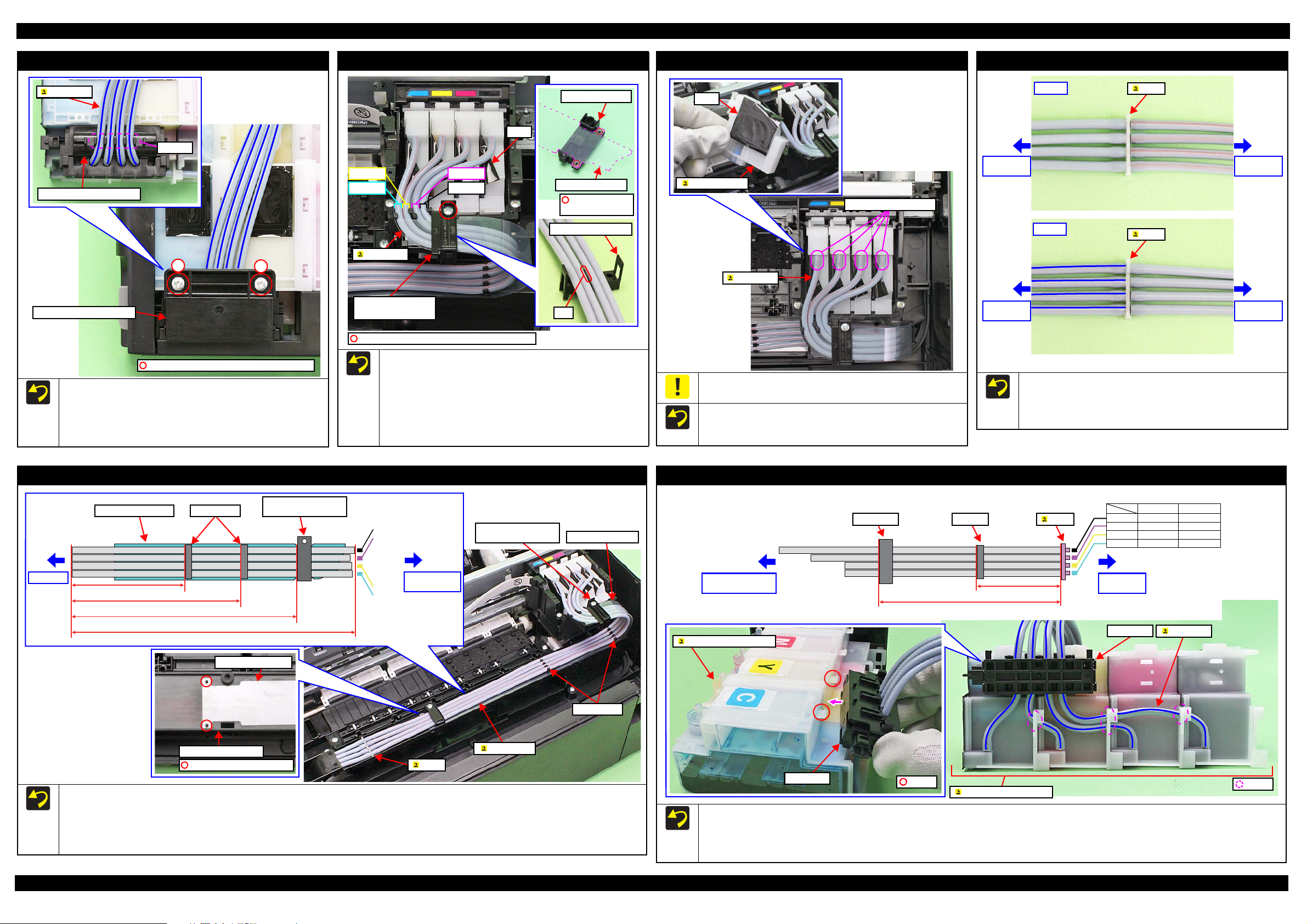
Tube Assy
Ink Tube Guide 1st
Ink Tubes
Ink Tube Guide 1st
Ink Tubes
C.B.P-TITE SCREW 2.5x5 (5.0 ~ 6.0 kgf·cm)
Ink Tube Guide 1st
Acetate tape (18 mm x 50 mm)
Front side
Acetate tape (18 mm x 50 mm)
Left side
Bottom left
Acetate tape (18 mm x 30 mm)
2
C.B.P-TITE SCREW 3x10 (5.0 ± 0.5 kgf·cm)
1
Ink Tube Guide 2nd
EJ Frame Assy
Rib
Bottom right
Right Cover / Left Cover / Bottom Cover
CR Front
CR Cover
The figures above indicate the hooks and ribs that secure the parts.
Ink Tube Guide 1st
Align the positioning holes (x2) of the CR Front with the
dowels (x2) of the Carriage.
Tighten the screws in the order indicated in the figure above.
Tighten the screws in the order indicated in the figure above.
After installing the CR Cover, move the Carriage from side to
side to make sure that the Tube Assy does not apply extra load
of carriage movement.
Ink Tube Guide 2nd / EJ Frame Assy
Align the ribs on the left/right side of the Ink Tube Guide 2nd with the frame as shown in the figure above.
Attach acetate tape in the position shown above to secure the Ink Tube Guide 2nd.
Tighten the screws of the Ink Tube Guide 2nd together with the EJ Frame Assy in the order indicated in the figure above.
When installing the Ink Tube Guide 1st, align the blue lines of the ink tubes (the red lines for L100/L101) in the same direction as shown in the
figure above, and be careful not to let the ink tubes go slack on the bottom of the Ink Tube Guide 1st.
After securing the Ink Tube Guide 1st, pull the ink tubes from the Ink Supply Tank Assy side to make sure that the ink tubes are not caught.
Attach acetate tape (x2) in the positions shown above to secure the Ink Tube Guide 1st.
Disassembly/Assembly Details of Disassembling/Reassembling by Parts/Unit 27
Confidential
Page 28
L200/L201/L100/L101 Revision A
1
C.B.P-TITE SCREW 3x6 (5.0 ~ 6.0 kgf·cm)
2
Tube Valve Holder Front
Grooves
Ink Tubes
Tube Valve Holder Rear
C.B.P-TITE SCREW 2.6x16 (5.0 ~ 6.0 kgf·cm)
Cyan
Yellow
Black
Magenta
Tube Holder Top/
Tube Holder Lower
Film
Ink Tubes
Tube Holder Top
Tube Guide Plate
Positioning hole
and dowel
Tube Holder Lower
Rib
Film
Adapter Assy
Opening for Ink Tubes
Ink Tubes
Valve Assy
side
Valve Assy
side
Tube Assy
side
Tube Assy
side
Front
Joint
Joint
Back
Joint side
Adapter Assy
side
Tube Guide Plate Clamps (x2)
Tube Holder Top/
Tube Holder Lower
Tube Guide Plate
Tube Holder Top/
Tube Holder Lower
Clamps (x2)
Joint
Tube Assy
Ink Tube Guide 2nd
Tube Guide Plate
Positioning hole and dowel
ClampValve case
Valve case
Tube Assy
side
Ink Supply Tank
Assy side
Hole
Length of Ink Tube
Joint
Ink Supply Tank Assy
Ink Tube
Valve Assy
Ink Supply Tank Assy
Hook
Tube Valve Holder Rear / Tube Valve Holder Front
When installing the Tube Valve Holder Front, align the blue
lines (the red lines for L100/L101) of the ink tubes in the same
direction as shown in the figure above, and route them through
the grooves of the Tube Valve Holder Front.
Tighten the screws in the order indicated in the figure above.
Tub e Ho ld er To p / Tube Ho lde r L owe r
Align the positioning holes (x2) of the Tube Guide Plate with
the dowels (x2) of the Tube Holder Top.
Route the ink tubes while avoiding the rib of the Tube Holder
Lower to prevent the tubes from getting caught by the tube holders.
Make sure to route the ink tubes as shown in the figure above
when installing the Tube Holder Top/Tube Holder Lower.
Route the ink tubes over the films of the Adapter Assy.
Adapter Assy
Be careful not to damage or peel off the film of the Adapter Assy.
When installing the ink tubes to the Adapter Assy, insert the ink
tubes with their red lines facing upward as shown in the figure
above.
Joint
Align the red lines and blue lines (the other red lines for L100/
L101) respectively in the same direction as shown in the figure
above, and insert them to the joint to the full to its base.
Be careful not to damage the ink tubes and joint.
Tube Assy
Black
Magenta
190 ± 1 mm
257 ± 1 mm
335 ± 1 mm
Before installing the Tube Assy, align the positioning holes (x2) of the Tube Guide Plate with the dowels (x2) of the Ink Tube Guide 2nd.
When installing the Tube Assy, attach the Clamps (x2)/Tube Holder Top/Tube Holder Lower/Tube Guide Plate in the positions shown in the
When installing the Tube Assy, align the red lines of the ink tubes in the same direction as shown in the figure above, and attach them without
420 ± 4.2 mm or 10% tolerance
figure above.
any slack.
Disassembly/Assembly Details of Disassembling/Reassembling by Parts/Unit 28
Yellow
Cyan
When installing the Valve Assy, attach the Clamp on the position shown in the figure above.
When installing the Valve Assy, align the blue lines of the ink tubes (the red lines for L100/L101) in the same direction as shown in the figure
above, and route them through the holes of the Ink Supply Tank Assy.
When installing the Valve Assy, secure it with the hooks (x2) of the Ink Supply Tank Assy.
Val ve A ss y
L200/L201: 310 mm
L100/L101: 290 mm
165 ± 1 mm
Black
Magenta
Yellow
Cyan
L100/L101L200/L201
380 mm400 mm
350 mm370 mm
325 mm345 mm
325 mm345 mm
Confidential
Page 29
L200/L201/L100/L101 Revision A
OK
Section A
Hole C
Ink Tube
NG
Section A
Hole C
Ink Tube
Tube Guide Plate Support
Hole C Hole B Hole C Hole B
Section A Section A
Hole A
NG
OK Tube Guide Plate
Tube Guide Plate Support
Cross-
section
Tube Guide Plate
Hole A
Tube Guide Plate
8.0 mm
Refilling Ink Label
16.5 mm
30.5 mm
6.4 mm
7.5 mm 7.5 mm
Valve Position Label
Left side
Voluntary Label
10.0 mm
45.0 mm
Middle Housing
1
C.B.P-TITE SCREW 3x6 (5.0 ~ 6.0 kgf·cm)
2
Ink Supply Holder Assy
Hook
Middle Housing
C.B.P-TITE SCREW 2.5x5
(5.0 ~ 6.0 kgf·cm)
Ink Tube Guide 1st
Hook
Joint
Ink Tube Guide 1st
Ink Supply Holder Assy Middle Housing
Ink Tube Guide 1st
Holes
Ink Tube
Ink Tube
Tube Guide Plate Support
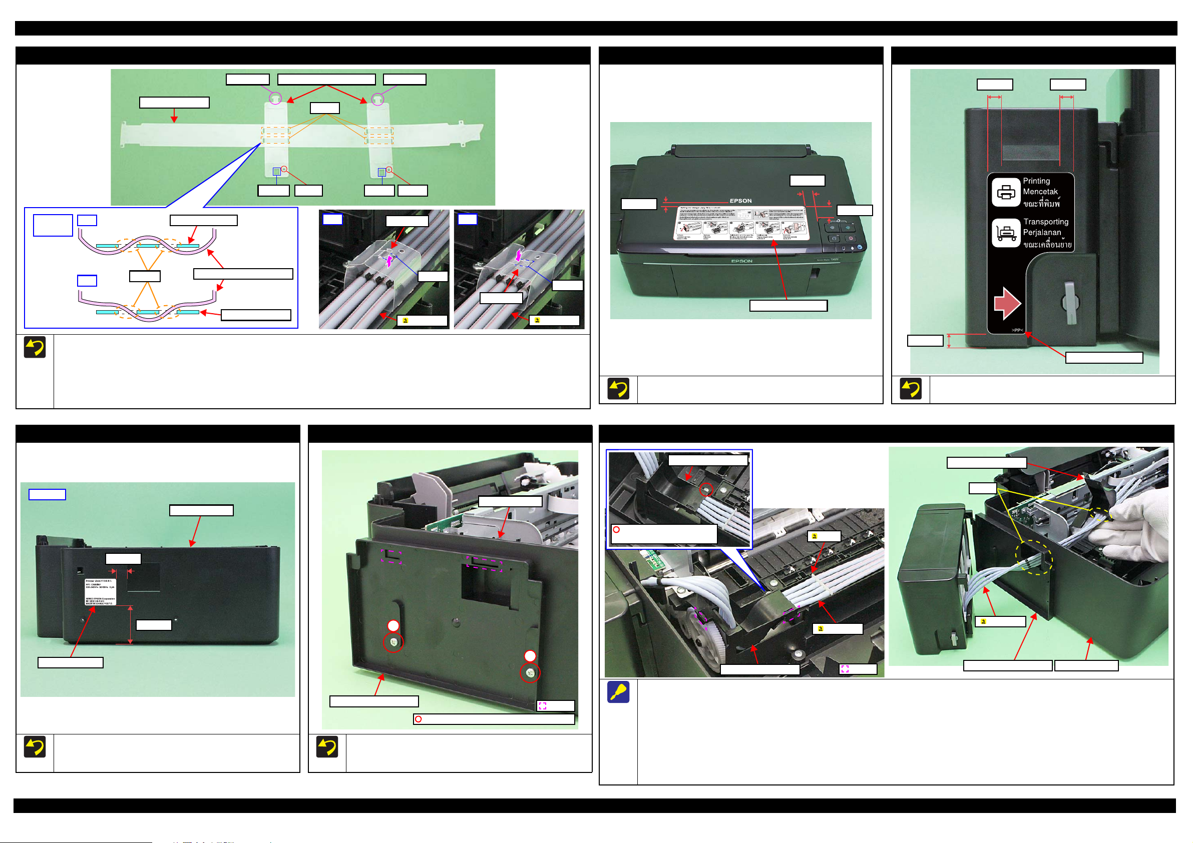
Refer to the figure above and follow the procedure below when installing the Tube Guide Plate Support.
1. Make sure that the hole B of the Tube Guide Plate Support comes on the right front side as seen from the front of the printer, and route the Tube
Guide Plate Support through the hole A (x2) of the Tube Guide Plate as shown in the “OK” image above.
2. Route the ink tubes along with the Tube Guide Plate.
3. Insert the section A of the Tube Guide Plate Support into the hole C of the Tube Guide Plate Support up from the bottom as shown in the “OK”
image above to secure it
Refilling Ink Label (L200/L201)
Attach the Refilling Ink Label on the position shown in the figure
above.
Valve Position Label
Attach the Valve Position Label on the position shown in the figure
above.
Middle Housing (L200/L201)
Ink Supply Holder Assy (L200/L201)
Ink Tube Guide 1st / Ink Supply Holder Assy (L200/L201)
Follow the procedure below when removing the Ink Supply Holder Assy / Ink Tube Guide 1st.
1. Remove the screws (x2) that secure the Ink Supply Holder Assy. (p 29)
2. Peel off the acetate tape (x2) that secure the Ink Tube Guide 1st. (p 27)
Disassembly/Assembly Details of Disassembling/Reassembling by Parts/Unit 29
When replacing the Middle Housing, peel off the Voluntary Label
from the old housing and attach it to the new housing as specified
in the figure above.
When installing the Ink Supply Holder Assy, align the hooks (x2)
with the hole of the Middle Housing, and tighten the screws in the
order indicated in the figure above.
3. Remove the screw (x1) that secures the Ink Tube Guide 1st.
4. Release the hooks (x2) that secure the Ink Tube Guide 1st, and remove it from the frame.
5. After confirming the Valve is closed, disconnect the Ink Tubes from the Joint. (p 10)
6. Pull out the Ink Tubes from the holes of the Middle Housing / Ink Supply Holder Assy / Ink Tube Guide 1st, and remove the Ink Supply Holder
Assy / Ink Tube Guide 1st.
Confidential
Page 30

L200/L201/L100/L101 Revision A
Bottom side
Hook
Upper Housing AssyStep 3
Upper Housing Assy
Panel FFC
Step 5
1
C.B.P-TITE SCREW 3x6 (5.0 ~ 6.0 kgf·cm)
Ink Supply Holder Assy
Hook
2
C.B.P-TITE SCREW 3x10 (5.0 ± 0.5 kgf·cm)
Upper Housing Assy
Upper Housing Assy
Ink Supply Holder Assy
Left side
Rear side
Step 1
Step 2
Step 4
Left side
Voluntary Label
5.0 mm
30.0 mm
23.2 mm
4.0 mm
4.0 mm
10.0 mm
Refilling Ink Label
Printer Cover
Hook
Hook
Joint
Ink Tube Guide 1st
Ink Supply Holder Assy
Ink Tube Guide 1st
Holes
Ink Tube
Ink Tube
C.B.P-TITE SCREW 2.5x5
(5.0 ~ 6.0 kgf·cm)
Ink Tube Guide 1st
Upper Housing Assy / Ink Supply Holder Assy (L100/L101)
Refilling Ink Label (L100/L101)
Printer Cover (L100/L101)
Attach the Refilling Ink Label on the position shown in the figure
above.
Be careful when removing the Printer Cover, because the hooks
(x2) are fragile and easily get damaged or softened.
Ink Tube Guide 1st / Ink Supply Holder Assy (L100/L101)
Do not lift the Upper Housing Assy too fast, since the Panel FFC is connected to the back of the Upper Housing Assy.
Be careful not to damage the hooks (x2) on the bottom left because these cannot be seen when removing.
Follow the procedure below when removing the Upper Housing Assy.
1. Remove the screws (x2) that secure the Ink Supply Holder Assy.
2. Remove the screws (x2) that secure the Upper Housing Assy.
3. Release the hooks (x8) that secure the Upper Housing Assy.
4. Lift the Upper Housing Assy while leaving the Ink Supply Holder Assy.
5. Disconnect the Panel FFC from the connector on the main board, and remove the Upper Housing Assy.
Disassembly/Assembly Details of Disassembling/Reassembling by Parts/Unit 30
When replacing the Upper Housing Assy, peel off the Voluntary Label from the old housing and attach it to the new housing as specified in the
figure above.
When installing the Ink Supply Holder Assy, align the hooks (x4) of it with the holes of the Upper Housing Assy and then tighten the screws in
the order indicated in the figure above.
Follow the procedure below when removing the Ink Supply Holder Assy / Ink Tube Guide 1st.
1. Remove the Upper Housing Assy. (p 30)
2. Peel off the acetate tape (x2) that secure the Ink Tube Guide 1st. (p 27)
3. Remove the screw (x1) that secures the Ink Tube Guide 1st.
4. Release the hooks (x2) that secure the Ink Tube Guide 1st, and remove it from the frame.
5. After confirming the Valve is closed, disconnect the Ink Tubes from the Joint. (p 10)
6. Pull out the Ink Tubes from the holes of the Ink Supply Holder Assy / Ink Tube Guide 1st, and remove the Ink Supply Holder Assy / Ink Tube
Guide 1st.
Confidential
Page 31
L200/L201/L100/L101 Revision A
Panel FFC
Rib
Double-sided tape
Panel FFC
Panel FFC
Ferrite Core
Bottom of the Scanner Unit
Scanner Motor cable
Hook
Section A
Scanner FFC
Ferrite Core
Housing
Pick Assy
Rib
CR Motor
CR Motor cable
Pick Assy
Rib A
Head FFC CR Motor cable Main Board
Main Board
PF Motor cable
Power Supply Unit Cable
PF Encoder FFC
Rib
Head FFC
Connect to CR Encoder
Head FFC
Rib
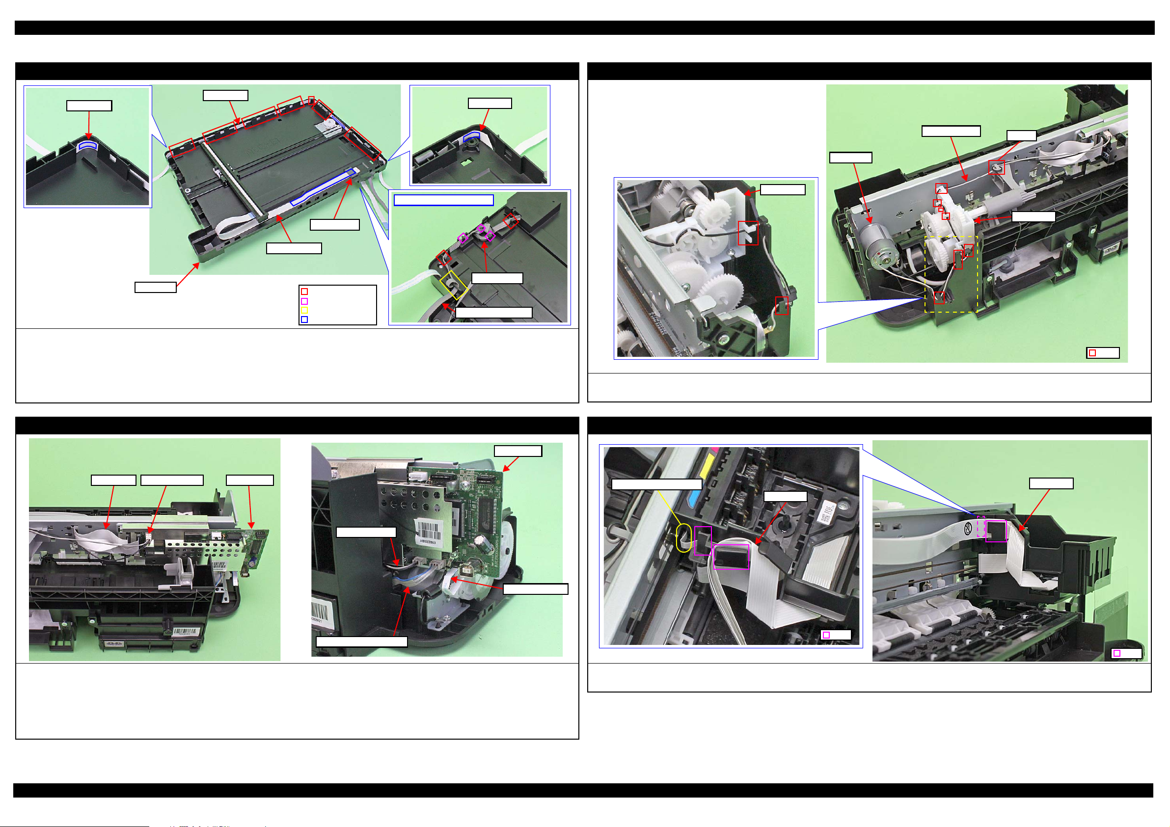
1.4 Routing FFCs/cables
Scanner Unit /CIS (L200/L201)
When routing the Panel FFC, route it through the ribs (x7) of the Housing, and secure with double-sided tape (x3).
When routing the Scanner FFC, secure it together with the Ferrite Core on the Housing with double-sided tape.
When routing the Scanner Motor cable, pay attention to the following instructions.
• Secure the Ferrite core with the hooks (x2) on the rear of the Scanner Unit.
• Route the Scanner Motor cable through the ribs (x2) and hook (x1) on the rear of the Scanner Unit, and through the hole of the section A and make one
turn around the frame of the section A.
CR Motor
Route the CR Motor cable through the ribs (x10) and make one turn around the rib A.
Route the CR Motor cable so as not to touch the surrounding gears.
Connect the following cable to the Main Board as shown in the figure above.
• PF Motor cable
• Power Supply Unit cable
• PF Encoder FFC
• CR Motor cable
• Head FFC
Main Board
Printhead / Carriage
Confirm the CR Encoder Head FFC is surely connected.
Route the Head FFC through the rib of the Carriage as shown above.
Disassembly/Assembly Routing FFCs/cables 31
Confidential
Page 32

L200/L201/L100/L101 Revision A
CR Encoder
Holder FFC
Head FFC
Hole
Step 2
Main Frame
Holder FFC
Head FFC
Step 1
Fold line
Main Frame
Step 3
Rib
Hook
Head FFC
Holder FFC
PF Motor
PF Motor cable
Ferrite Core
Rib
Panel FFC
Upper Housing
Ferrite Core
Upper Housing
Panel Board
Panel FFC
Hook
Double-sided tape (8 x 20 mm)
Head FFC
When installing the Head FFC to the Carriage, route the Head FFC through the rib (x1) on the rear of the Carriage, and connect the Head FFC to the CR
Encoder.
When installing the Head FFC to the Main Frame, route the Head FFC in the procedure below and connect it to the Main Board.
1. Align the fold line of the Head FFC with the rib (x1) of the Holder FFC, and route the FFC through the Holder FFC as shown in the figure above.
2. Route the Head FFC through the hole of the Main Frame.
3. Align the hooks (x4) of the Holder FFC with the holes (x4) on the Main Frame, and secure the Holder FFC to the Main Frame by sliding it to the 80-digit side.
PF Motor
Set the Ferrite Core of the PF Motor cable into the ribs of the Frame Base.
Panel Board (L100/L101)
When routing the Panel FFC, follow the instructions below.
1. Route it through the Ferrite Core and the hook (x1).
2. Secure the FFC with double-sided tape (x2) to the Upper Housing, and then secure the Ferrite core with the hooks (x2).
Disassembly/Assembly Routing FFCs/cables 32
Confidential
Page 33

CHAPTER 2
ADJUSTMENT
Confidential
Page 34

L200/L201/L100/L101 Revision A
2.1 Required Adjustments
The table below lists the required adjustments depending upon the parts being repaired or replaced. Find the part(s) you removed
or replaced, and check which adjustment(s) must be carried out.
Note: <Meaning of the marks in the table>
“O” indicates that the adjustment must be carried out. “O
removed or replaced multiple parts, make sure to check the required adjustments for the all parts. And when multiple adjustments must be carried out, be sure to carry out
them in the order given in the “Priority” row.
Priority 1 2 3 4 5 6 7 8 9
Adjustment Item EEPROM data copy Initial setting Maintenance counter reset Ink charge Head ID input Top margin adjustment Head angular adjustment Bi-D adjustment PF band adjustment
To copy adjustment values or the
like stored on the old Main Board
to the new board when the Main
Board needs to be replaced.
Main board
Printhead
Power Supply Unit
LD Roller Assy
Part Name
CR Motor
EJ Roller
Main Frame
Carriage Assy
Purpose
Remove
Replace
(Read OK)
Replace
(Read NG)
Remove
Replace
Remove
Replace
Remove
Replace
Remove
Replace
Remove
Replace
Remove
Replace
Remove
Replace
*
” indicates that the adjustment is recommended. “---” indicates that the adjustment is not required. If you have
Table 2-1. Required Adjustment List
To apply settings for the target
market after replacing the Main
Board.
--- --- --- --- --- O O O O
O --- --- --- --- --- --- --- ---
--- O
--- --- --- --- --- O O O O
--- --- --- O O O O O O
--- --- --- --- --- O O O O
--- --- --- --- --- O O O O
--- --- --- --- --- O O O O
--- --- --- --- --- O O O O
--- --- --- --- --- O O O O
--- --- --- --- --- O O O O
--- --- --- --- --- O O O O
--- --- --- --- --- O O O O
--- --- --- --- --- O O O O
--- --- --- --- --- O O O O
--- --- --- --- --- O O O O
--- --- --- --- --- O O O O
To reset the waste ink counter /
the ink tube counter after
replacing the Waste Ink Pad / the
Tube Assy.
O
(Replace the pad)
To fill ink inside the new
Printhead to make it ready for
print after replacing the
Printhead.
---OOOOO
When the EEPROM Data Copy cannot be made for the Main Board that needs to be replaced, the Waste
Ink Tray Assy must be replaced after replacing the Main Board with a new one.
After all required adjustments are completed, use the “Final check pattern print” function to print all
adjustment patterns for final check. If you find a problem with the printout patterns, carry out the
adjustment again.
When using a new Main Board for replacing the Printer Mechanism, the Initial setting must have been
made to the Main Board.
To correct characteristic
variation of the replaced
printhead by entering its
Printhead ID (Head ID).
To correct top margin of
printout.
To correct tilt of the Printhead
caused at the installation by
software.
To correct print start timing in bidirectional printing by software.
To correct variations in paper
feed accuracy in order to achieve
higher print quality in band
printing.
Printout pattern
How to judge
Adjustment program
Tool
OK
--- --- --- --- ---
--- --- --- --- ---
See Figure 2-1.
Check if the top edge of the
paper is within -3 to +3 steps
from the standard line.
See “ 2.2 Details of Adjustments
(p36)” for the details.
NG
NG
Examine the printout patterns for
each of the four modes, and enter
the value for the pattern with no
gap and overlap for each mode.
Examine the printout patterns for
each of the four modes, and enter
the value for the pattern with no
gap and overlap for each mode.
OOOOOOOOO
--- --- --- --- --- --- --- --- ---
OK
NG
NG
OK
NG
NG
Examine the printout patterns
and enter the value for the pattern
with no overlap and gap between
the two rectangles.
Adjustment Required Adjustments 34
Confidential
Page 35

L200/L201/L100/L101 Revision A
Table 2-1. Required Adjustment List
Priority 1 2 3 4 5 6 7 8 9
Adjustment Item EEPROM data copy Initial setting Maintenance counter reset Ink charge Head ID input Top margin adjustment Head angular adjustment Bi-D adjustment PF band adjustment
Upper Paper Guide
PF Roller
Waste Ink Pads
Cap Unit
PF Motor
Part Name
PF Encoder/
PF Scale
CR Scale
Tube Assy
Purpose
Remove
Replace
Remove
Replace
Remove
Replace
Remove
Replace
Remove
Replace
Remove
Replace
Remove
Replace
Remove
Replace
To copy adjustment values or the
like stored on the old Main Board
to the new board when the Main
Board needs to be replaced.
--- --- --- --- --- O O O O
--- --- --- --- --- O O O O
--- --- --- --- --- O O O O
--- --- --- --- --- O O O O
--- --- --- --- --- O O O ---
--- --- O --- --- O O O ---
--- --- --- --- --- O O O O
--- --- --- --- --- O O O O
--- --- --- --- --- O O O O
--- --- --- --- --- O O O O
--- --- --- --- --- O O O O
--- --- --- --- --- O O O O
--- --- --- --- --- O O O O
--- --- --- --- --- O O O O
--- --- --- --- --- --- --- --- ---
--- --- O --- --- --- --- --- ---
To apply settings for the target
market after replacing the Main
Board.
To reset the waste ink counter /
the ink tube counter after
replacing the Waste Ink Pad / the
Tube Assy.
To fill ink inside the new
Printhead to make it ready for
print after replacing the
Printhead.
To correct characteristic
variation of the replaced
printhead by entering its
Printhead ID (Head ID).
To correct top margin of
printout.
To correct tilt of the Printhead
caused at the installation by
software.
To correct print start timing in bidirectional printing by software.
To correct variations in paper
feed accuracy in order to achieve
higher print quality in band
printing.
Printout pattern
How to judge
Adjustment program
Tool
--- --- --- --- ---
--- --- --- --- ---
OOOOOOOOO
--- --- --- --- --- --- --- --- ---
Note: In addition to the above adjustments, the following functions can be executed in the Adjustment Program. Refer to the Adjustment Program for the functions and their usage.
• Ink charge / Cleaning / Power cleaning (Each cleaning function with two options, whether counting up the waste ink counter or not.)
• Small ink counter reset
• Ink counter offset (with two options, whether counting up the waste ink counter or not.)
• Get Status (check for the ink consumption counter and accumulated number of printing)
See Figure 2-1.
Check if the top edge of the
paper is within -3 to +3 steps
from the standard line.
See “ 2.2 Details of Adjustments
(p36)” for the details.
OK
NG
NG
Examine the printout patterns for
each of the four modes, and enter
the value for the pattern with no
gap and overlap for each mode.
OK
NG
NG
Examine the printout patterns for
each of the four modes, and enter
the value for the pattern with no
gap and overlap for each mode.
OK
NG
NG
Examine the printout patterns
and enter the value for the pattern
with no overlap and gap between
the two rectangles.
Adjustment Required Adjustments 35
Confidential
Page 36
L200/L201/L100/L101 Revision A
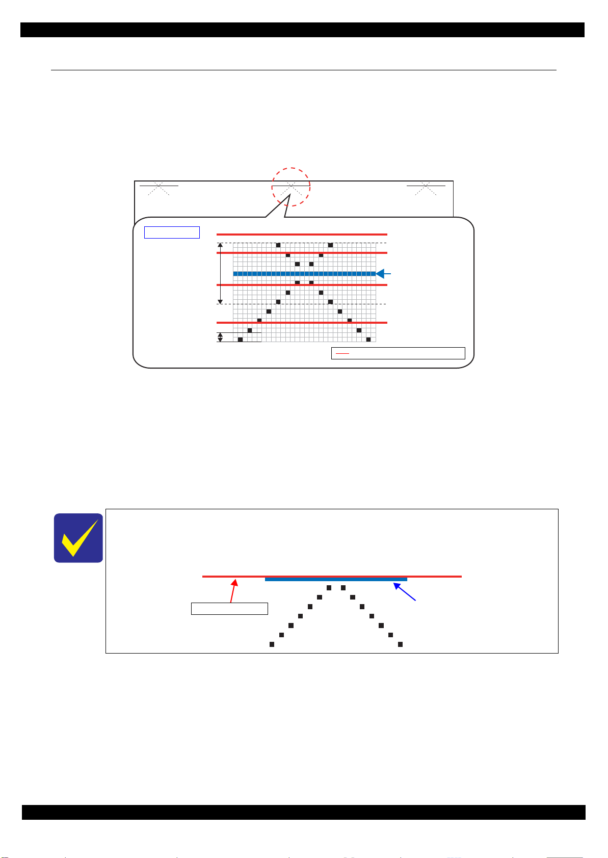
How to Judge
Within ±3 steps from
standard line is OK
NG:-4 steps from
standard line
NG:+5 steps from
standard line
OK
OK
Standard line
1 Step
Position of the top edge of paper
Standard line
Top edge of paper
2.2 Details of Adjustments
This section provides adjustment procedures for which explanation in details is necessary. See “ 2.1 Required
Adjustments (p34)” for the adjustments not explained here.
2.2.1 TOP Margin Adjustment
Three adjustment patterns are printed on the top of the paper as shown in Figure 2-1.
Figure 2-1. Top Margin Adjustment Printout Pattern
How to Judge
Check if the top edge of the paper is within -3 to +3 steps from the standard line.
Additional Information
If it is not within the OK range, select the adjustment value (-4 to +4 steps) on the adjustment program to adjust the top edge
of paper until it becomes within -3 to +3 steps from the standard line. Then, print the adjustment pattern again to check the
result.
The patterns are printed on three sections. If those three patterns are in different position to the top
edge of paper, the paper was fed on a skew. Set the papers correctly and print it again to adjust the
top margin correctly.
The following pattern is printed with the optimal adjustment value.
Adjustment Details of Adjustments 36
Confidential
Page 37

CHAPTER 3
MAINTENANCE
Confidential
Page 38
L200/L201/L100/L101 Revision A
3.1 Overview
This section provides information to maintain the printer in its optimum condition.
3.1.1 Cleaning
Except for the printhead, there are no other mechanism parts or units that require periodic cleaning. However, if
need arises, clean the component observing the following instructions.
Instructions for cleaning
Exterior parts such as housing
Wipe dirt off with a soft clean cloth moistened with water. For glossy or transparent parts, use of unwoven cloth is
recommended to avoid scratching those parts.
Inside of the printer
Remove paper dust with a vacuum cleaner.
Rubber or plastic rollers such as an LD roller used to feed paper
If paper dust adhered to the rollers decreases the frictional force of the rollers and the rollers cannot properly feed
paper, wipe off the paper dust with a soft cloth moistened with diluted alcohol.
Instructions for cleaning ink stains
Wipe the stains off with a cloth wrung out of diluted alcohol.
Do not use alcohol for cleaning the transparent parts. Doing so may cause them to get
cloudy.
When wiping paper dust off the LD roller, be careful not to rub against the surface
asperity.
To minimize the effect on the parts, use diluted alcohol such as 70% diluted ether.
After using alcohol for cleaning, make sure to wipe the part off with a soft dry dust-free
cloth to remove alcohol traces fully.
3.1.2 Lubrication
The type and amount of the grease used to lubricate the printer parts are determined based on the results of the
internal evaluations. Therefore, refer to “ 3.2 Lubrication Points and Instructions (p39)” for the repairing
procedures below, and apply the specified type and amount of the grease to the specified part of the printer
mechanism.
Before applying the grease, make sure to wipe off old grease completely with BEMCOT.
Grease
Type Name EPSON Part Code Supplier
Grease G-45 (TBD) 1033657 (TBD) EPSON
Grease G-71 1304682 EPSON
Grease G-74 1409257 EPSON
Tools
Name Availability EPSON Part Code
Injector O ---
Brush O ---
Maintenance Overview 38
Confidential
Page 39

L200/L201/L100/L101 Revision A
Right side
Left side
Lubrication Point
Lubrication Point
Cross-section view
1 mm
Lubrication area
Left side
Bearing
EJ Roller
Frame Base
Lubrication Point
3.2 mm
13 mm
5.1 mm
5 mm
6.6 mm
8.6 mm
Lubrication Point
316.4 mm
377.87 mm
35 mm
2 mm 2 mm
Main Frame
3.2 Lubrication Points and Instructions
<Lubrication Point>
Rail of the Paper Support
Assy
<Type>
G-74
<Application Amount>
Appropriate amount
<Remarks>
Apply with brush.
Keep the lubrication
within the rail. (No
grease outside of the
rail is allowed.)
<Lubrication Point>
Shaft on the Scanner
Housing
<Type>
G-45 (TBD)
<Application Amount>
Appropriate amount
<Remarks>
Apply with brush.
Keep the lubrication
within the rail. (No
grease outside of the
rail is allowed.)
Figure 3-1. Lubrication on Paper Support Assy (L200/L201)
<Lubrication Point>
1. Ribs (x20) of the
Frame Base
(contacting points with
the EJ Roller)
2. Bearings of the
Frame Base
(contacting points with
the EJ Roller)
3. Shaft on the right
side of the EJ Roller
<Type>
G-71
<Application Amount>
1. 0.04g / point
2. Appropriate amount
3. Appropriate amount
<Remarks>
Apply with injector.
Figure 3-2. Lubrication on Scanner Unit
<Lubrication Point>
Contacting points (x5)
with the Carriage Unit
on the front side of the
Main Frame
Contacting points (x2)
with the Driven Pulley
Holder
<Type>
G-71
<Application Amount>
Appropriate amount
<Remarks>
Apply with injector.
Lubrication area:
Top side of the
Main Frame: 316.4
mm (x1)
Bottom side of the
Main Frame:
377.87 mm (x4)
Figure 3-3. Lubrication on EJ Roller
Figure 3-4. Lubrication on Main Frame
Maintenance Lubrication Points and Instructions 39
Confidential
Page 40

L200/L201/L100/L101 Revision A
Driven Pulley Holder
Lubrication Point
Lubrication Point
Lubrication Point
Left Pick Housing
Right Pick Housing
Head Pick Housing
Lubrication Point
Right side
Left side
Lubrication Point
<Lubrication Point>
Contacting points (x2)
with the Driven Pulley
<Type>
G-71
<Application Amount>
φ 1 mm x 1 mm
<Remarks>
Apply with injector.
<Lubrication Point>
Sliding surface between
the Roller Idler Pick and
Spring Roller Idler Pick
<Type>
G-71
<Application Amount>
Appropriate amount
<Remarks>
Apply with brush.
<Lubrication Point>
Ribs (x3) of the Frame
Base (contacting points
with the PF Roller)
<Type>
G-71
<Application Amount>
φ 1 mm x around shaft
(x 3)
<Remarks>
Apply with injector.
Figure 3-5. Lubrication on Driven Pulley Holder Figure 3-6. Lubrication on Roller Idler Pick Assy
<Lubrication Point>
Contacting points (x5)
between the shafts and
bushings of the Head
Pick Housing
Contacting point (x1)
with the Right Pick
Housing
Contacting points (x3)
between the shafts and
bushings of the Left
Pick Housing
<Type>
G-71
<Application Amount>
Appropriate amount
<Remarks>
Apply with injector.
Figure 3-7. Lubrication on PF Roller
<Lubrication Point>
Rail of the Paper Support
Assy
<Type>
G-74
<Application Amount>
Appropriate amount
<Remarks>
Apply with brush.
Keep the lubrication
within the rail. (No
grease outside of the
rail is allowed.)
Figure 3-9. Lubrication on Paper Support Assy (L100/L101)
Figure 3-8. Lubrication on LD Roller Assy
Maintenance Lubrication Points and Instructions 40
Confidential
Page 41

CHAPTER 4
APPENDIX
Confidential
Page 42

L200/L201/L100/L101 Revision A
lock
lockisreleased
4.1 Power-On Sequence
This section describes the power-on sequences for this product. The preconditions are as follows.
Condition
Completing ink charge.
No paper on the paper path.
The Printhead is capped with the Cap of the Ink System.
The Carriage is locked by the CR Lock.
Table 4-1. Operation of the power-on sequence
Operation
1. Checking for waste ink overflow
1-1.Reads out the protection counter value to check waste ink overflow.
2. Seeking the home position
2-1.The carriage moves to the 80-digit side slowly and confirms it touches the CR lock.
2-2.The carriage moves to the 0-digit side slowly to leave from the CR lock.
*1
Carriage/PF roller
movement and position
*2
2-3.Checks if paper does not exist with the PE sensor and the PF Motor rotates clockwise to release the CR lock.
2-4.The carriage moves to the 80-digit side slowly and confirms that the CR lock is released.
2-5.The carriage quickly moves to the 80-digit side by the Left Frame.
2-6.After the carriage continuously moves to the 80-digit side slowly and confirms it touches the Left Frame, sets the
distance from the home position to the Left Frame as the theoretical value.
2-7.The carriage quickly moves to the 0-digit side and slows down as it gets to its home position, and stops there.
3. Low temperature operation sequence
3-1.The carriage moves back and forth between the 0-digit side and the 80-digit side for two times.
*3
(Continued to the next page...)
Appendix Power-On Sequence 42
Confidential
Page 43

L200/L201/L100/L101 Revision A
Table 4-1. Operation of the power-on sequence
Operation
4. Detecting ink cartridge and initializing ink system
4-1.The carriage moves to the 80-digit side for IES detection.
4-2.The carriage returns to its home position.
4-3.The carriage slowly moves to the CR lock set position.
4-4.The PF Motor rotates clockwise.
4-5.The PF Motor rotates counterclockwise and sets the CR lock.
4-6.The carriage slowly returns to its home position.
*1
* 4
Note *1 : The rotation direction of the PF Motor is as follows.
Clockwise direction : Paper is fed normally
Counterclockwise direction : Paper is fed backward
*2: The conditions of the CR lock are as follows.
Red: CR lock is set
White: CR lock is released
o
*3: Executed when the detected temperature is under 5
C (41oF) by the thermistor on the Printhead.
*4: The empty sanction operation may occur depending on the situation.
Carriage/PF roller
movement and position
*2
Appendix Power-On Sequence 43
Confidential
Page 44

L200/L201/L100/L101 Revision A
4.2 Connector Diagram
Cable connections of this printer are shown below.
Scanner Unit
Only L200/L201
CIS Module
Printhead
CR Motor
Scanner Motor
Panel Unit
L200/L201
Panel Board
CR Encoder
J3 J2
J5
Main Board
PF Motor
J8
J7 J11 J10
J301
J9
PS Board
Figure 4-1. Connector Diagram
J4
AC in
J201
Panel Unit
L100/L101
Panel Board
J201
PF Encoder
Appendix Connector Diagram 44
Confidential
Page 45

L200/L201/L100/L101 Revision A
4.3 Troubleshooting
This section describes the troubleshooting workflow and fatal error information.
4.3.1 Troubleshooting Workflow
The following page describes the troubleshooting workflow. Follow the flow when troubleshooting problems.
Appendix Troubleshooting 45
Confidential
Page 46

L200/L201/L100/L101 Revision A
Start
Turn on the printer
Does printer turn on the
power?
Yes
Is Power-on sequence
finished without error?
Yes
Standby condition
Perform “Flow A”
What is returned reason?
Scanner unit
failure
*3
No
No
1
Printer failure only
Major problem without
error message
No Power
[Presumable Cause]
• Power Supply Board damage
• Main Board damage
[Major Troubleshooting]
• Power Supply Board
replacement
• Main Board replacement
*1
Flow A
Start
Print check pattern
Is printing operation
finished without error?
Yes
Is printing operation
finished without trouble?
Yes
No
No
1
Fatal error
Please refer to “ 4.3.2 Fatal Error
Code (p47)”for troubleshooting.
Major problem with error message
Maintenance error
[Occurrence Condition]
This error occurs when
maintenance counter in EEPROM
exceeds the specified value.
[Major Occurrence Timing]
• Power-on timing
• Print start timing
• Cleaning timing
[Troubleshooting]
• Porous Pad replacement
• Tube Assy replacement
• Maintenance counter reset
Ink End error
[Occurrence Condition]
This error occurs when ink in Ink
Cartridge is empty.
[Major Occurrence Timing]
• Power-on timing
• Print start timing
• Cleaning timing
• Print timing
[Troubleshooting]
• Refill the ink(s)
Paper Jam error
Please refer to “ Paper Jam error”
of “Error occurs in printing
operation”.
Copy an image
Is scanning operation
finished without
trouble?
Yes
*4
Finish
No
Scanner failure
[Presumable Cause]
• Contamination of Scanner
Glass
• Contamination of Document
Pad
• CIS Unit bonding failure
• CIS Unit damage
• Scanner Motor damage
[Major Troubleshooting]
• Scanner Glass cleaning
• Document Pad cleaning
• Document Pad replacement
• CIS Unit replacement
• Scanner Motor replacement
Major problem without error message
Poor Printing
[Phenomenon]
• Poor printing quality
• Ink stain on paper
• Dot missing
• Paper eject without printing
[Presumable Cause]
• Driver / Panel mis-setting
• Contamination of CR scale
• Contamination of Printhead
cover
• Printhead damage
• Ink clogging of Printhead
• Contamination on Cap Unit /
Wiper of Ink System Assy
• Ink System Assy damage
• Float of Porous Pad on Paper
Guide Front
•Narrow PG
• PE Sensor Lever damage
• PE Sensor damage
[Major Troubleshooting]
• Driver / Panel re-setting
• CR Scale replacement
• Printhead cover cleaning
• Printhead cleaning
• Ink Cartridge replacement
• Printhead replacement
• Rubber cleaning of Cap Unit
• Ink System Assy replacement
• Porous Pad re-installation
•PG readjustment
• Printer Mechanism
replacement
• PE Sensor Lever replacement
Return previous flow
[Presumable Cause]
• Use of 3rd party media
• Edge guide mis-setting
• Foreign material
• Part come-off
[Major Troubleshooting]
• Recommendation of EPSON
media
• Edge guide re-setting
• Foreign material removal
• Part re-installation
• Roller replacement
[Presumable Cause]
• Foreign material
• Insufficient grease
•Gear damage
[Major Troubleshooting]
• Foreign material removal
• Lubrication of grease
• Gear replacement
[Presumable Cause]
• Valve closes
• Ink tank ventilation film gets
wet
• Ink tube crumples
• Ink tube connection is
incomplete.
[Major Troubleshooting]
• Open valve
• Ink tank replacement
• Ink tube re-installation
Poor Paper Loading
Abnormal Noise
Blank Printing
Paper Jam error
[Occurrence Condition]
This error occurs when top/
bottom of paper is not detected by
PE Sensor in the specified steps of
paper feeding operation correctly.
[Major Occurrence Timing]
• Power-on timing
• Paper loading timing
• Paper eject timing
[Major Troubleshooting]
1 Push “Start” button to eject the
paper.
•Success
Start paper feeding operation
again if printer has print data.
•Fail
Occur paper jam error again.
2 If fail in the above 1), remove
the paper.
3 Push “Start” button again.
•Success
Start paper feeding operation
again if printer has print data.
•Fail
Occur paper jam error again.
4 If fail in the above 3), check
foreign material / part comeoff / PE Sensor Lever / Porous
Pad on Paper Guide Front /
Main board.
No Paper error
[Occurrence Condition]
This error occurs when top of
paper is not detected by PE Sensor
in the specified steps of paper
loading operation correctly.
(No paper / No loading / No
cassette / large paper skew)
[Major Occurrence Timing]
• Paper loading timing
[Major Troubleshooting]
1 Put papers in cassette and push
“Start” button.
2 If a paper stops before reaching
PE Sensor, remove it and
check the paper condition.
3 A) If no damage in the above 2),
set edge guide correctly after
putting papers in cassette and
retry.
B) If damage in the above 2),
check foreign materials /
parts come-off / parts
transformation in paper
path.
4 If not resolved by 3-A) & 3-B),
check foreign material / Part
come-off / surface condition of
LD Roller / PE Sensor Lever /
Main Board / PF Motor.
This flowchart is compiled based on the following contents.
Our experience regarding the quality problem.
ESK’s repair data on FY08 / FY09 models.
Printer Mechanism specification for L200/L201/L100/L101.
Double Feed error
[Occurrence Condition]
This error occurs on the following
case.
• A paper is ejected without
printing during paper loading
operation.
• Actual paper length is longer
than theoretical one.
[Major Occurrence Timing]
• Paper loading timing
• Paper feed timing
• Paper eject timing
[Troubleshooting]
• PE Sensor Lever replacement
• Main Board replacement
*2
*1: If the printer can turn on but turns off right away, the protection circuit may cut off
the power due to an error such as a circuit failure.
*2: Only for manual duplex print
*3: Only for L200/L201.
*4: In case of “Not Trouble Found”, check fatal error code.
Appendix Troubleshooting Workflow 46
Confidential
Page 47

L200/L201/L100/L101 Revision A
4.3.2 Fatal Error Code
This section describes the fatal error code and the possible cause for this product.
Printer fatal error list
Table 4-2. Fatal Error List (Printer)
Error type
DC motor
error
Printhead
system error
Sequence
error
Logic error 0CH Analog-ASIC communication error • Main Board failure
Error
code
01H Carrier stall error
04H Print incomplete error
02H Feed stall error
03H Head hot error
08H Head temperature error
09H Environmental temperature error
0AH Carrier multiple drive error
Error name Possible cause
• CR Encoder failure (contaminated/detached scale, Encoder Board failure)
• Motor driver failure (Main Board failure)
• CR Motor failure
• Tooth skip of the CR Timing Belt
• Improper tension of the CR Timing Belt
• Carriage overload error (paper jam/foreign object)
• Cable disconnection
• CR Encoder failure (contaminated/detached scale, Encoder Board failure)
• Motor driver failure (Main Board failure)
• CR Motor failure
• Tooth skip of the CR Timing Belt
• Improper tension of the CR Timing Belt
• Carriage overload error (paper jam/foreign object)
• PF Encoder failure (contaminated/detached scale, Encoder Board failure)
• PF Motor failure
• PF drive mechanism overload (paper jam/foreign object)
• Cable disconnection
• Printhead failure
• Head FFC disconnection
• Printhead failure
• Main Board failure
• Head FFC disconnection
• Main Board failure
• Head FFC disconnection
---*
Note "*" : Not occurs except in manufacturing process.
Scanner fatal error list
Table 4-3. Fatal Error List (Scanner)
Error code Error name Possible cause
• CIS Unit failure
01H Scanner HP detection error
• Scanner Unit failure
• Dust in Scanner Unit
• Cable/FFC disconnection
Appendix Fatal Error Code 47
Confidential
 Loading...