

Page 1

Return to main menu
IM-X4 0
Using this online operator’s guid e
The words on the left side of this screen are
bookmark s
for all the
topics in this guide .
Use the
scroll ba r
next to the bookmarks to find any topic you
want. Click a bookmark to instantly jump to its topic. (If you wish,
you can increase the size of the bookmark area by dragging the
dividing bar to the right. )
Use the
Click the
zoo m
Fin d
tools to magnify or reduce the page display .
button if you want to search for a particular term.
(However, using the bookmarks is usually quicker. )
Complete online documentation for Acrobat Reader is located in the Help directory for Acrobat Reader .
Page 2
IM-X40
User’s Manual
Page 3

Printed in Japan
-iii
Page 4

Copyright Information
All rights reserved. No part of this publication may be reproduced, stored in a
retrieval system, or transmitted in any form or by any means, electronic, mechanical,
photocopying, recording, or otherwise, without the prior written permission of Seiko
Epson Corporation. No patent liability is assumed with respect to the use of the
information contained herein. While every precaution has been taken in the
preparation of this book, Seiko Epson Corporation assumes no responsibility for
errors or omissions. Neither is any liability assumed for damages resulting from the
use of the information contained herein.
Neither Seiko Epson Corporation nor its affiliates shall be liable to the purchaser of
this product or third parties for damages, losses, costs, or expenses incurred by the
purchasers or third parties as a result of accident, misuse, or abuse of this product or
unauthorized modifications, repairs, or alterations to this product, or (excluding the
U.S.) failure to strictly comply with Seiko Epson Corporation’s operating and
maintenance instructions.
Seiko Epson Corporation shall not be liable against any damages or problems arising
from the use of any options or any consumable products other than those designated
as Original EPSON Products or EPSON Approved Products by Seiko Epson
Corporation.
EPSON is a registered trademark of Seiko Epson Corporation.
Intel is a registered trademark of Intel Corporation.
i486 is a trademark of Intel Corporation.
IBM, PC/AT, and PS/2 are registered trademarks of International Business
Machines Corporation.
MAXIMIZER is a trademark of SystemSoft Corporation.
Microsoft is a registered trademark of Microsoft Corporation.
Windows is a registered trademark of Microsoft Corporation.
General Notice: Other product and company names used herein are for
identification purposes only and may be trademarks of their respective companies.
NOTICE:
The contents of this manual are subject to change without notice.
Copyright 1996 © by Seiko Epson Corporation, Nagano, Japan.
400575700
ii
Page 5

FCC CLASS A
FCC COMPLIANCE STATEMENT FOR AMERICAN USERS
This equipment has been tested and found to comply with the limits for a Class A
digital device, pursuant to Part 15 of the FCC Rules. These limits are designed to
provide reasonable protection against harmful interference when the equipment is
operated in a commercial environment.
This equipment generates, uses, and can radiate radio frequency energy and, if not
installed and used in accordance with the instruction manual, may cause harmful
interference to radio communications. Operation of this equipment in a residential
area is likely to cause harmful interference, in which case the user will be required to
correct the interference at his own expense.
WARNING
The connection of a non-shielded interface cable to this product will invalidate the
FCC Verification of this device and may cause interference levels which exceed the
limits established by the FCC for this equipment.
You are cautioned that changes or modifications not expressly approved by the
party responsible for compliance could void your authority to operate the
equipment.
FOR CANADIAN USERS
This Class A digital apparatus meets all requirements of the Canadian InterferenceCausing Equipment Regulations.
Cet appareil numérique de la classe A respecte toutes les exigences du Règlement
sur le matériel brouilleur du Canada.
iii
Page 6

Nickel-Cadmium (Ni-Cd) Rechargeable Battery
Aufladbare Nickel-Cadmium (Ni-Cd) Batterie
Batterie rechargeable au Nickel-Cadmium (Ni-Cd)
R
PBRC
B
R
C
PBRC
Ni-Cd
Ni-Cd Cd
Attention:
The product that you have purchased contains a Ni-Cd rechargeable battery. The
battery should be recycled or disposed of properly. When your battery can no longer
be recharged, please disconnect the battery according to this manual’s instructions,
and check with your local solid waste officials for details in your area for recycling
options or proper disposal.
Achtung:
Das von Ihnen erworbene Produkt enthält eine aufladbare Ni-Cd-Batterie. Die
Batterie sollte wiederverwertet bzw. korrekt entsorgt werden. Kann die Batterie
nicht mehr aufgeladen werden, entfernen Sie die Batterie, wie in dieser Anleitung
beschrieben, und erkundigen Sie sich bei der an Ihrem Wohnort zuständigen
Behörde bezüglich Wiederverwertung bzw. korrekter Entsorgung.
Attention:
Le produit que vous venez d’acheter contient une batterie rechargeable Ni-Cd. La
batterie doit être recyclée ou jetée convenablement. Lorsque la batterie est morte, ne
pouvant plus être rechargée, la déconnecter conformément aux instructions du
mode d’emploi et vérifier avec les autorités locales pour les détails sur le recyclage et
la collecte sélective des ordures.
iv
Page 7

Modular type connector
You see the following caution label near the modular type connector on the back
panel of the product.
Caution:
The product uses a modular type connector exclusively for the DM display. Never
plug a telephone line into this connector.
v
Page 8

Introduction
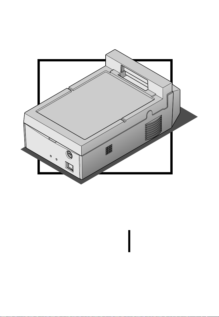
The IM-X40 control unit (referred to as the control unit in this
document) is an intelligent terminal for the point of sale (POS)
environment. The control unit offers the following features:
❏ A fast SL enhanced Intel
®
i486™SX2 processor gives you the
power and speed you need to process your transactions.
❏ Because the TM printer fits on top of the control unit, you can
install it in a small area, giving you more counter space.
❏ The PC-based, open-architecture control unit contains one
standard 16-bit ISA expansion slot and a second expansion slot
for a PCMCIA expansion module, allowing you to expand your
system.
❏ Using a standard SIMM, you can install up to 32MB of memory
in a control unit.
❏ The built-in IBM
PC/AT
®
compatible keyboards, so you can select the best one
®
PS/2® keyboard port can support a variety of
for your environment.
❏ Four serial ports and a combined parallel/optical coupled
interface adapter (OCIA) port allow you to connect several
industry-standard peripherals to meet your specific transaction
processing needs.
❏ The built-in DM display port allows you to install an EPSON
®
DM-D102 or DM-D203 customer display without requiring you
to use one of the additional serial ports.
❏ The built-in VGA port allows you to connect a standard VGA
or SVGA monitor directly to the control unit.
Introduction 1
Page 9

❏ A Nickel-Cadmium (Ni-Cd) battery is available as a option. In
the event of a power failure, the Ni-Cd battery backup gives
you time (about a minute) to save your current transaction
before the control unit shuts down.
❏ Several levels of security keep your critical data safe. The front
panel locks, ensuring controlled access to the floppy disk drive
and making the removal of the IM module impossible. Multiple
levels of passwords keep your system, your data, and your
cash drawer secure.
❏ Sophisticated power management functions ensure that you
use only the power you need to process your transactions.
❏ The hard disk drive is easy to remove and reinstall. If a system
fails, you can be using your same data on a different control
unit almost immediately.
❏ The easy-to-update flash ROM has 112KB available for a user-
defined program, while 144KB is used by the system.
❏ The BIOS is PC/AT compatible—this means you can run all
your favorite PC programs as well as your application-specific
software.
❏ Built-in device diagnostics make troubleshooting fast and easy.
❏ Local bus video.
2 Introduction
Page 10
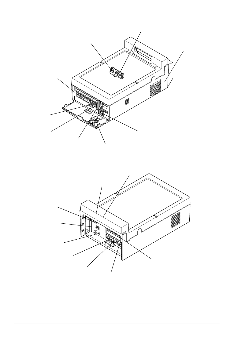
The illustrations below show the part names of the control unit.
(These illustrations show the floppy disk drive installed.)
COM1 port
TM printer
power outlet
Floppy disk drive
Hard disk
access LED
IM-X40
control unit
Power LED
DM display port
Power inlet
Transportation
screw storage hole
COM2 port
Power switch
Reset
Key lock
COM4 port
COM3 port
LPT1/OCIA port
Keyboard port
VGA port
Control unit overview
Introduction 3
Page 11

Handling Guidelines
Observe these guidelines when handling the control unit:
❏ Make sure you read the safety instructions for the power
supply before you attach or remove it.
❏ Never plug a telephone line into the DM display port.
❏ Make sure you always set a password for accessing the drawer
kickout test in the device diagnostics utility. The drawer
kickout test checks if the cash drawer opens correctly.
However, anyone can access the test if you do not define a
password.
❏ Make sure you charge the batteries (Ni-Cd* and Lithium
batteries) in the control unit. These rechargeable batteries are
not charged fully at the factory. (*Ni-Cd battery is an option.)
❏ Do not block any slots or openings on the control unit. These
are provided for the ventilation necessary to ensure reliable
operation and protection from overheating.
❏ Make sure that any device connected to the AC outlet of the
power supply does not consume more than 150 VA.
❏ Make sure that the total power requirements of all the devices
getting their power from the control unit do not exceed the
control unit power limitations.
❏ When you transport the control unit in its shipping container,
make sure you replace the transportation screw.
❏ Make sure you lock the IM module to the lower plastic housing
using the lock on the front panel. The module could fall from
the housing if it isn’t secured.
❏ Never hold the control unit by the back cover. This cover
cannot support the weight of the unit, so it may fall onto the
floor.
4 Introduction
Page 12

❏ You see the following label on the back panel of the control
unit:
This connector
cannot be used.
Do not remove this label.
Option
❏ PCMCIA expansion module
This expansion module supports two Type I or Type II PC
cards or one Type III PC card.
❏ Ni-Cd battery
The rechargeable Ni-Cd battery supplies power to the control
unit for approximately one minute in the event of a power
failure. This allows you to save your current transaction before
the control unit shuts down.
A 3.5-inch floppy disk drive, 2.5-inch hard disk drives, and
SIMMs are also available for the control unit.
Introduction 5
Page 13
List of Terms
The following list identifies terms used in this manual and the
corresponding names printed on each circuit board.
Manual term Printed name on circuit board
Connector board I/C board
External I/O board EXT I/O board
Modular board MO board
PCMCIA expansion module PCMCIA board
Power board PWR board
System board CPU board
Warnings, Cautions, and Notes
Notes and precautions in this manual are identified by their level of
importance, as defined below.
WARNINGS
provide information that must be observed to prevent harm
(not life-threatening) to the user.
Cautions
provide information that must be observed to prevent
damage to the equipment or loss of data.
Notes:
provide important information and useful tips on handling the
equipment.
6 Introduction
Page 14

Contents
Chapter 1
How to Use This Chapter . . . . . . . . . . . . . . . . . . . . . . . . . . . . . . . . . . . . . . . . . . . . . . . 1-1
Unpacking the Control Unit . . . . . . . . . . . . . . . . . . . . . . . . . . . . . . . . . . . . . . . . . . . . 1-3
Setting Up the IM Module . . . . . . . . . . . . . . . . . . . . . . . . . . . . . . . . . . . . . . . . . . . . . . 1-4
Removing the Transportation Screw . . . . . . . . . . . . . . . . . . . . . . . . . . . . . . . . . . 1-4
Removing the IM Module From the Plastic Housing . . . . . . . . . . . . . . . . . . . . 1-5
Removing the External I/O Board . . . . . . . . . . . . . . . . . . . . . . . . . . . . . . . . . . . . 1-7
Removing the Cover . . . . . . . . . . . . . . . . . . . . . . . . . . . . . . . . . . . . . . . . . . . . . . . 1-9
Locating Components . . . . . . . . . . . . . . . . . . . . . . . . . . . . . . . . . . . . . . . . . . . . . . 1-11
Setting the Jumpers . . . . . . . . . . . . . . . . . . . . . . . . . . . . . . . . . . . . . . . . . . . . . . . . 1-12
Installing or Removing a SIMM . . . . . . . . . . . . . . . . . . . . . . . . . . . . . . . . . . . . . . 1-18
Installing a Hard Disk Drive . . . . . . . . . . . . . . . . . . . . . . . . . . . . . . . . . . . . . . . . . 1-20
Installing a Floppy Disk Drive . . . . . . . . . . . . . . . . . . . . . . . . . . . . . . . . . . . . . . . 1-22
Installing a PCMCIA Expansion Module (option) . . . . . . . . . . . . . . . . . . . . . . 1-26
Installing an ISA Card . . . . . . . . . . . . . . . . . . . . . . . . . . . . . . . . . . . . . . . . . . . . . . 1-29
Installing the Battery Pack (option) . . . . . . . . . . . . . . . . . . . . . . . . . . . . . . . . . . . 1-31
Installieren der Batterie-Einheit . . . . . . . . . . . . . . . . . . . . . . . . . . . . . . . . . . . . . . 1-31
Installation de la batterie . . . . . . . . . . . . . . . . . . . . . . . . . . . . . . . . . . . . . . . . . . . . 1-31
Setting Up the Control Unit . . . . . . . . . . . . . . . . . . . . . . . . . . . . . . . . . . . . . . . . . . . . . 1-36
Connecting the TM printer . . . . . . . . . . . . . . . . . . . . . . . . . . . . . . . . . . . . . . . . . . 1-36
Connecting Peripherals . . . . . . . . . . . . . . . . . . . . . . . . . . . . . . . . . . . . . . . . . . . . . 1-39
Connecting the Power Supply . . . . . . . . . . . . . . . . . . . . . . . . . . . . . . . . . . . . . . . 1-40
Attaching the Back Cover . . . . . . . . . . . . . . . . . . . . . . . . . . . . . . . . . . . . . . . . . . . 1-42
Setting a Password for the Drawer Kick-out Test . . . . . . . . . . . . . . . . . . . . . . . 1-42
Charging the Batteries . . . . . . . . . . . . . . . . . . . . . . . . . . . . . . . . . . . . . . . . . . . . . . . . . . 1-43
Lithium Battery . . . . . . . . . . . . . . . . . . . . . . . . . . . . . . . . . . . . . . . . . . . . . . . . . . . . 1-43
Ni-Cd Battery (option) . . . . . . . . . . . . . . . . . . . . . . . . . . . . . . . . . . . . . . . . . . . . . . 1-44
Installation
Chapter 2
Using the System Configuration Utility . . . . . . . . . . . . . . . . . . . . . . . . . . . . . . . . . . . 2-1
Starting the System Configuration Utility . . . . . . . . . . . . . . . . . . . . . . . . . . . . . 2-2
Changing Options in the System Configuration Utility . . . . . . . . . . . . . . . . . . 2-3
Setting the Date and Time . . . . . . . . . . . . . . . . . . . . . . . . . . . . . . . . . . . . . . . . . . . 2-3
Setting the COM Ports . . . . . . . . . . . . . . . . . . . . . . . . . . . . . . . . . . . . . . . . . . . . . . 2-4
Setting the LPT Port Address . . . . . . . . . . . . . . . . . . . . . . . . . . . . . . . . . . . . . . . . 2-4
Setting the LPT Port MODE Option . . . . . . . . . . . . . . . . . . . . . . . . . . . . . . . . . . 2-4
Setting the Floppy Disk Drive . . . . . . . . . . . . . . . . . . . . . . . . . . . . . . . . . . . . . . . 2-5
Setting the Hard Disk Drive . . . . . . . . . . . . . . . . . . . . . . . . . . . . . . . . . . . . . . . . . 2-5
Setting the Video Display Type . . . . . . . . . . . . . . . . . . . . . . . . . . . . . . . . . . . . . . 2-6
Using System Utilities
vii
Page 15

Setting the Quick Boot Option . . . . . . . . . . . . . . . . . . . . . . . . . . . . . . . . . . . . . . . 2-6
Setting the Num Lock Option . . . . . . . . . . . . . . . . . . . . . . . . . . . . . . . . . . . . . . . 2-7
Setting the Boot Speed (CPU Speed) . . . . . . . . . . . . . . . . . . . . . . . . . . . . . . . . . . 2-7
Setting the Keyboard Options . . . . . . . . . . . . . . . . . . . . . . . . . . . . . . . . . . . . . . . 2-7
Setting Passwords . . . . . . . . . . . . . . . . . . . . . . . . . . . . . . . . . . . . . . . . . . . . . . . . . 2-8
Enabling the On-board Controllers . . . . . . . . . . . . . . . . . . . . . . . . . . . . . . . . . . . 2-9
Setting Memory Options . . . . . . . . . . . . . . . . . . . . . . . . . . . . . . . . . . . . . . . . . . . . 2-10
Exiting the System Configuration Utility . . . . . . . . . . . . . . . . . . . . . . . . . . . . . . 2-11
Setting Power Management Options . . . . . . . . . . . . . . . . . . . . . . . . . . . . . . . . . . . . . 2-11
Setting the Power Management Controls . . . . . . . . . . . . . . . . . . . . . . . . . . . . . . 2-12
Defining System Power Management Criteria . . . . . . . . . . . . . . . . . . . . . . . . . 2-12
Defining Device Power Management Criteria . . . . . . . . . . . . . . . . . . . . . . . . . . 2-14
Exiting From the Power Management Utility . . . . . . . . . . . . . . . . . . . . . . . . . . 2-15
Using Device Diagnostics . . . . . . . . . . . . . . . . . . . . . . . . . . . . . . . . . . . . . . . . . . . 2-16
Device Diagnostics Utility Conditions. . . . . . . . . . . . . . . . . . . . . . . . . . . . . . . . . 2-17
Starting Device Diagnostics . . . . . . . . . . . . . . . . . . . . . . . . . . . . . . . . . . . . . . . . . 2-19
Device Diagnostics Screen . . . . . . . . . . . . . . . . . . . . . . . . . . . . . . . . . . . . . . . . . . 2-20
TM/Drawer . . . . . . . . . . . . . . . . . . . . . . . . . . . . . . . . . . . . . . . . . . . . . . . . . . . . . . . 2-20
DM . . . . . . . . . . . . . . . . . . . . . . . . . . . . . . . . . . . . . . . . . . . . . . . . . . . . . . . . . . . . . . 2-22
Using the Setup Menu . . . . . . . . . . . . . . . . . . . . . . . . . . . . . . . . . . . . . . . . . . . . . . 2-25
Running Device-Tests . . . . . . . . . . . . . . . . . . . . . . . . . . . . . . . . . . . . . . . . . . . . . . 2-26
Initializing Device Diagnostics . . . . . . . . . . . . . . . . . . . . . . . . . . . . . . . . . . . . . . . 2-29
Leaving Device Diagnostics . . . . . . . . . . . . . . . . . . . . . . . . . . . . . . . . . . . . . . . . . 2-29
Chapter 3 Troubleshooting
Error Handling . . . . . . . . . . . . . . . . . . . . . . . . . . . . . . . . . . . . . . . . . . . . . . . . . . . . . . . . 3-1
Warning Messages . . . . . . . . . . . . . . . . . . . . . . . . . . . . . . . . . . . . . . . . . . . . . . . . . 3-2
Fatal Error Messages . . . . . . . . . . . . . . . . . . . . . . . . . . . . . . . . . . . . . . . . . . . . . . . 3-4
Beep Codes . . . . . . . . . . . . . . . . . . . . . . . . . . . . . . . . . . . . . . . . . . . . . . . . . . . . . . . 3-5
The Control Unit Will Not Start . . . . . . . . . . . . . . . . . . . . . . . . . . . . . . . . . . . . . . . . . . 3-5
Battery Backup Does Not Work (optional Ni-Cd battery) . . . . . . . . . . . . . . . . . . . . 3-6
The Control Unit Does Not Respond . . . . . . . . . . . . . . . . . . . . . . . . . . . . . . . . . . . . . 3-7
The Control Unit Shuts Down . . . . . . . . . . . . . . . . . . . . . . . . . . . . . . . . . . . . . . . . . . . 3-7
Keyboard Problems . . . . . . . . . . . . . . . . . . . . . . . . . . . . . . . . . . . . . . . . . . . . . . . . . . . . 3-7
Monitor Problems . . . . . . . . . . . . . . . . . . . . . . . . . . . . . . . . . . . . . . . . . . . . . . . . . . . . . . 3-8
The EPSON DM-D Display Problems . . . . . . . . . . . . . . . . . . . . . . . . . . . . . . . . . . . . . 3-8
Floppy Disk Problems . . . . . . . . . . . . . . . . . . . . . . . . . . . . . . . . . . . . . . . . . . . . . . . . . . 3-9
Floppy Disk Drive Problems . . . . . . . . . . . . . . . . . . . . . . . . . . . . . . . . . . . . . . . . . . . . 3-9
Hard Disk Drive Problems . . . . . . . . . . . . . . . . . . . . . . . . . . . . . . . . . . . . . . . . . . . . . . 3-10
TM Printer Problems . . . . . . . . . . . . . . . . . . . . . . . . . . . . . . . . . . . . . . . . . . . . . . . . . . . 3-10
Serial Port Problems . . . . . . . . . . . . . . . . . . . . . . . . . . . . . . . . . . . . . . . . . . . . . . . . . . . . 3-11
Parallel or OCIA Port Problems . . . . . . . . . . . . . . . . . . . . . . . . . . . . . . . . . . . . . . . . . . 3-11
Cash Drawer Problems . . . . . . . . . . . . . . . . . . . . . . . . . . . . . . . . . . . . . . . . . . . . . . . . . 3-12
PC Card Problems . . . . . . . . . . . . . . . . . . . . . . . . . . . . . . . . . . . . . . . . . . . . . . . . . . . . . 3-12
Port 80h Diagnostic Codes . . . . . . . . . . . . . . . . . . . . . . . . . . . . . . . . . . . . . . . . . . . . . . 3-12
viii
Page 16

Appendix A Control Unit Specifications
CPU and Memory . . . . . . . . . . . . . . . . . . . . . . . . . . . . . . . . . . . . . . . . . . . . . . . . . . . . . . A-1
Controllers . . . . . . . . . . . . . . . . . . . . . . . . . . . . . . . . . . . . . . . . . . . . . . . . . . . . . . . . . . . . A-2
Interfaces. . . . . . . . . . . . . . . . . . . . . . . . . . . . . . . . . . . . . . . . . . . . . . . . . . . . . . . . . . . . . . A-2
Batteries . . . . . . . . . . . . . . . . . . . . . . . . . . . . . . . . . . . . . . . . . . . . . . . . . . . . . . . . . . . . . . A-4
Security . . . . . . . . . . . . . . . . . . . . . . . . . . . . . . . . . . . . . . . . . . . . . . . . . . . . . . . . . . . . . . . A-4
Switches . . . . . . . . . . . . . . . . . . . . . . . . . . . . . . . . . . . . . . . . . . . . . . . . . . . . . . . . . . . . . . A-5
Indicators (LEDs). . . . . . . . . . . . . . . . . . . . . . . . . . . . . . . . . . . . . . . . . . . . . . . . . . . . . . . A-5
System Utilities . . . . . . . . . . . . . . . . . . . . . . . . . . . . . . . . . . . . . . . . . . . . . . . . . . . . . . . . A-5
Power Supply Descriptions. . . . . . . . . . . . . . . . . . . . . . . . . . . . . . . . . . . . . . . . . . . . . . A-6
Power Limits of the Control unit . . . . . . . . . . . . . . . . . . . . . . . . . . . . . . . . . . . . . A-7
Dimensions. . . . . . . . . . . . . . . . . . . . . . . . . . . . . . . . . . . . . . . . . . . . . . . . . . . . . . . . . . . . A-8
Environmental Requirements . . . . . . . . . . . . . . . . . . . . . . . . . . . . . . . . . . . . . . . . . . . . A-9
DMA Assignments . . . . . . . . . . . . . . . . . . . . . . . . . . . . . . . . . . . . . . . . . . . . . . . . . . . . A-10
Hardware Interrupts. . . . . . . . . . . . . . . . . . . . . . . . . . . . . . . . . . . . . . . . . . . . . . . . . . . A-10
System Memory Map . . . . . . . . . . . . . . . . . . . . . . . . . . . . . . . . . . . . . . . . . . . . . . . . . . A-11
System I/O Map . . . . . . . . . . . . . . . . . . . . . . . . . . . . . . . . . . . . . . . . . . . . . . . . . . . . . . A-12
Connector Pin Assignments . . . . . . . . . . . . . . . . . . . . . . . . . . . . . . . . . . . . . . . . . . . . A-13
Appendix B Loop Back Connectors
Appendix C SIMM Specifications
ix
Page 17

Chapter 1
Installation
This chapter explains how to set up your hardware. For
configuring your system using the system utility software, see the
next chapter.
How to Use This Chapter
For a list of the components included with the control unit, see
page 1-3.
If you install the optional battery pack in your control unit, turn to
page 1-31. To remove the transportation screw, turn to page 1-4.
The IM module is a control unit without the housing. Before you
can install internal components or change jumper settings, you
need to remove the IM module from the plastic housing, and then
remove the external I/O board and the cover.
Check the table below to see where these procedures are described;
then follow the instructions on that page.
If you want to See page
Remove the IM module from the plastic housing 1-5
Remove the external I/O board from the IM module 1-7
Remove the cover from the IM module 1-9
Installation 1-1
Page 18

Once you have the cover off of the IM module, turn to the
appropriate sections in this chapter and follow the instructions for
installing the component.
If you want to See page
Set jumpers 1-12
Install a SIMM 1-18
Install a hard disk drive 1-20
Install a floppy disk drive 1-22
Install a PCMCIA expansion module 1-26
Install an ISA card 1-29
When you have the components installed, replace the cover and the
external I/O board; then return the IM module to the plastic
housing. Then turn to page 1-36 for instructions on setting up the
control unit.
1-2 Installation
Page 19
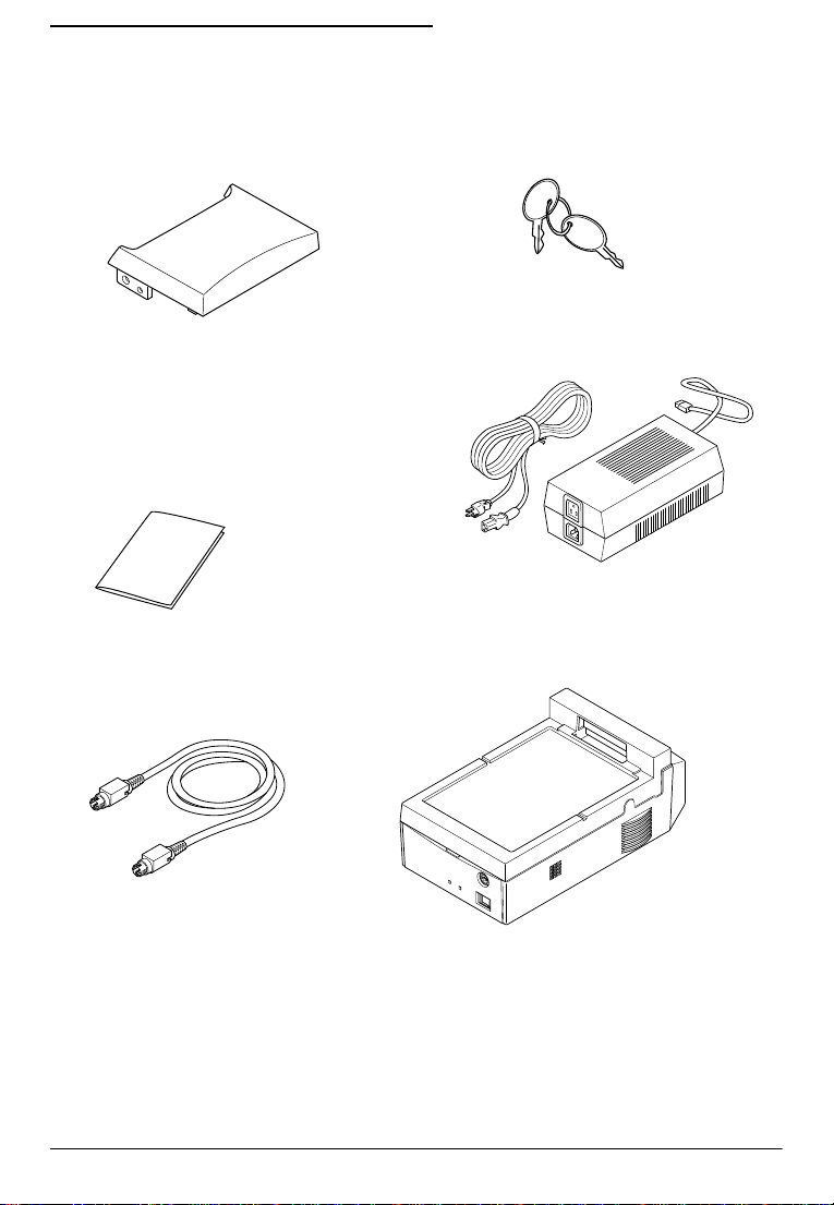
Unpacking the Control Unit
When you unpack the control unit, make sure you have these
items:
Keys (2 pieces)
Back cover
Safety instructions
TM printer power cable
Power cord
Power supply
Control unit
If any of these items are damaged or missing, please contact your
dealer for assistance.
Installation 1-3
Page 20

Setting Up the IM Module
Before you perform any steps described in this section, make sure
the control unit and any peripheral devices are off. Disconnect the
power supply from the control unit. Also disconnect any cables
that are connected to the control unit.
Caution
Never install options, change jumper settings, or connect
peripherals when the control unit is turned on or the power
supply is connected to the control unit.
Removing the Transportation Screw
The IM module is secured to the plastic housing during shipping
by a transportation screw. Follow these steps to remove this screw:
1. Turn the control unit over so that the bottom of the plastic
housing is facing up; then locate the transportation screw.
2. Use a small coin or a flat head screwdriver to turn the screw
counterclockwise and remove it.
1-4 Installation
Page 21
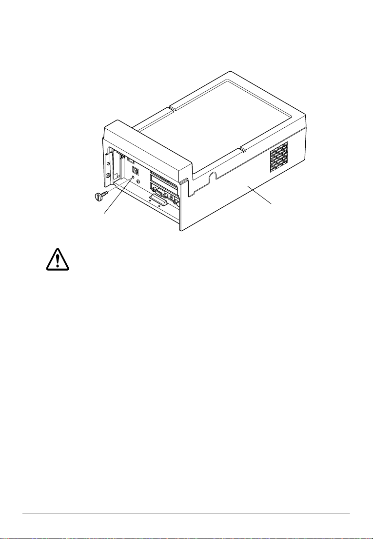
3. Locate the storage hole on the back panel of the control unit.
4. Secure the transportation screw to the storage hole in the back
panel.
Transportation
screw storage hole
Plastic housing
Caution
When you transport the control unit in its shipping container,
make sure you replace the transportation screw in the
bottom of the control unit.
Removing the IM Module From the Plastic Housing
Before you can install or remove any components from the IM
module or change jumper settings, you need to remove the IM
module from the plastic housing. Follow these steps:
1. Make sure that the transportation screw has been removed.
(See page 1-4.)
2. Use the key provided to open the lock on the front panel of the
plastic housing; then open the front panel.
Installation 1-5
Page 22
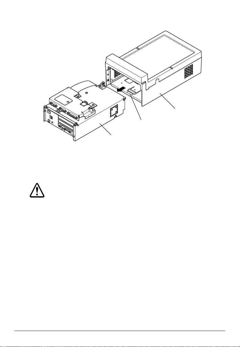
3. Hold down the tab on the plastic housing as you pull the IM
module out, as shown below:
Plastic housing
Tab
IM Module
When you are ready to replace the IM module in the plastic
housing, slide it in, until it is all the way in the housing. Close the
front panel and use the key to lock it.
Caution
Make sure you lock the IM module to the plastic housing
using the lock on the front panel. The module could fall from
the housing if it isn’t secured.
1-6 Installation
Page 23
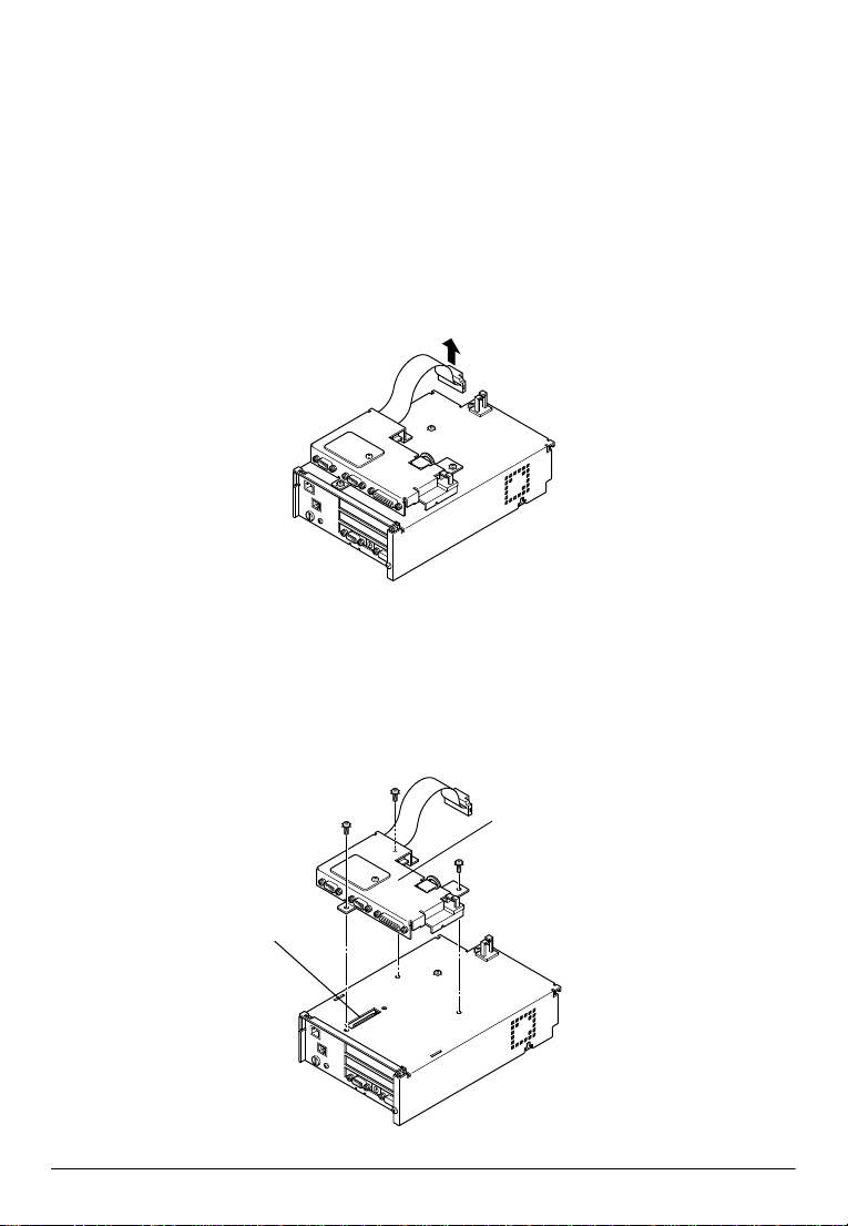
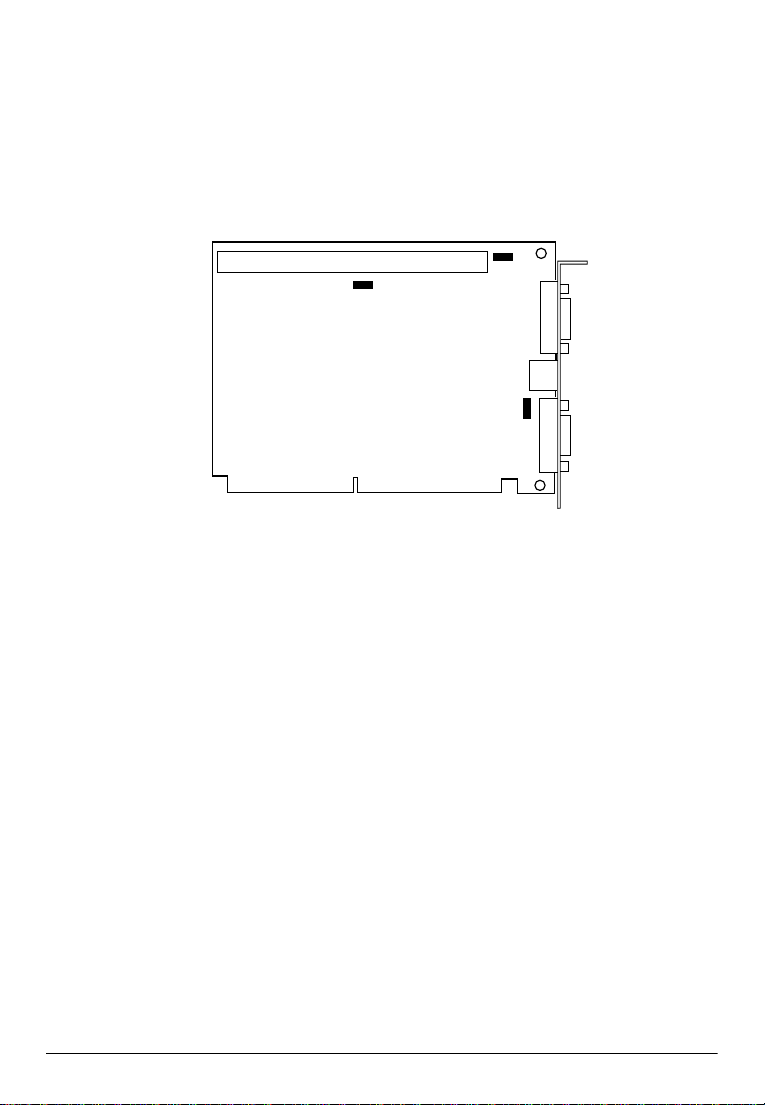
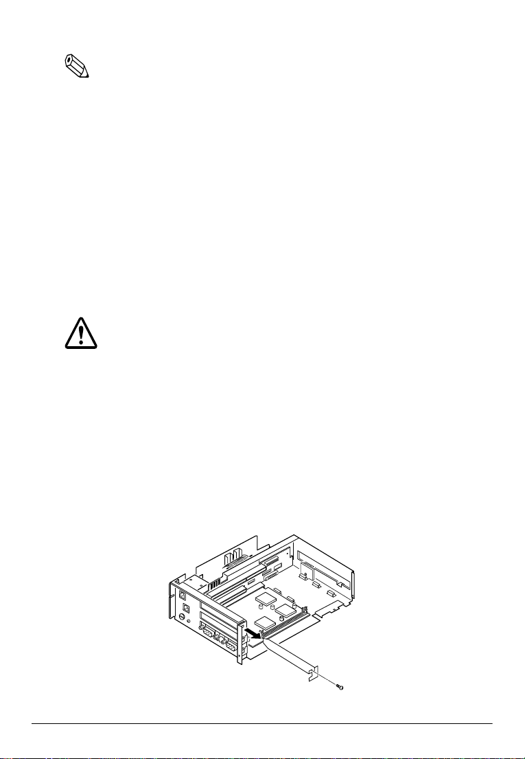
Removing the External I/O Board
The external I/O board connects to the connector board of the IM
module to provide three additional serial ports (COM1, COM3 and
COM4) and a parallel port that can also function as an OCIA port
(LPT1/OCIA). You must remove the external I/O board before you
can remove the cover on the IM module. Follow these steps:
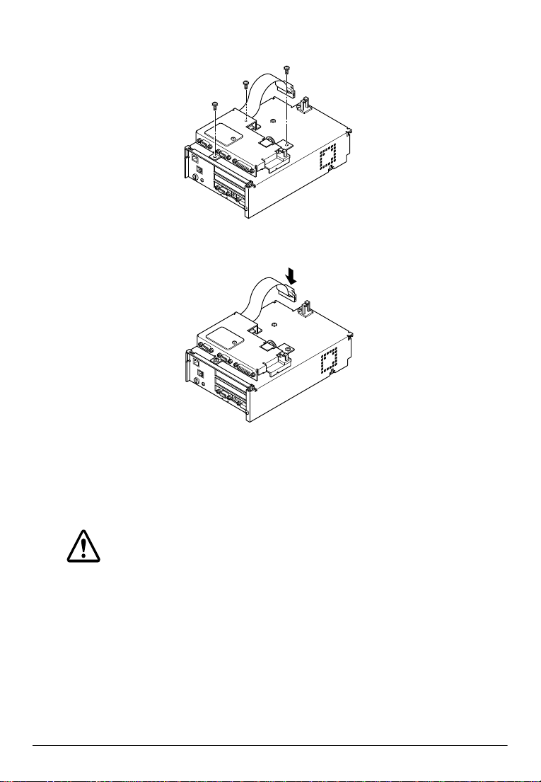
1. Disconnect the connector as shown in the illustration below.
2. Use a Phillips screwdriver to remove the three screws securing
the external I/O board to the cover.
3. Lift the external I/O board straight up to disconnect it from the
IM module, as shown below; then set it aside.
External I/O
board connector
External
I/O board
Installation 1-7
Page 24
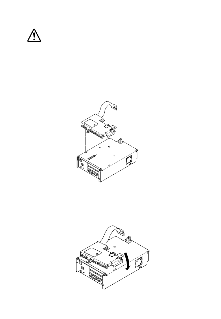
Once you have replaced the cover, you can replace the external
I/O board. Follow these steps:
Caution
Be sure to follow the steps below to replace the external I/O
board. If you replace the external I/O board incorrectly, you
could damage the connectors on the external I/O board
and the IM module.
1. Insert the tab on one side of the external I/O board into the slit
on the top of the cover, as shown below:
2. Gently lower the other side of the external I/O board, then
push the external I/O board in gently until you feel the
connector fit into place.
1-8 Installation
Page 25
3. Secure the external I/O board to the IM module with the three
retaining screws.
4. Connect the connector shown below.
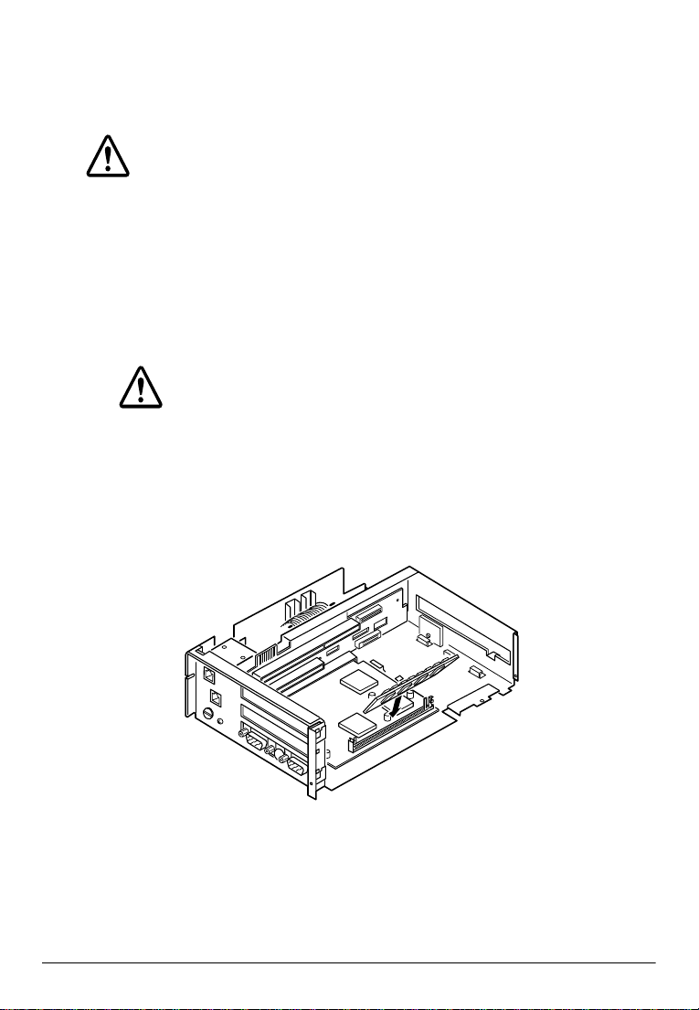
Removing the Cover
You need to remove the cover on the IM module to install drives or
other internal components or to change jumper settings.
Caution
Components on the internal boards can get hot. After you
turn off the control unit, wait at least 10 minutes for the
component to cool before you remove the IM module cover.
Follow these steps:
1. Remove the external I/O board, as described above.
Installation 1-9
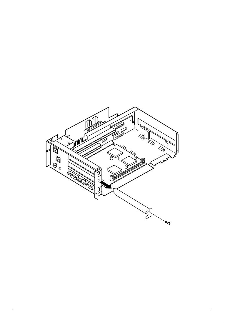
Page 26
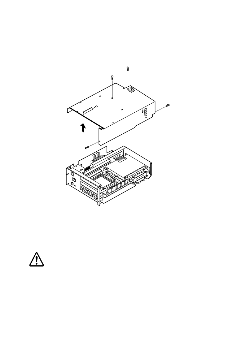
2. Use a Phillips screwdriver to remove the two additional screws
on the top of the cover that secure it to the control unit. Also
remove the two screws that secure the cover to the sides of the
chassis.
3. Lift the cover straight up, until it clears the chassis, as shown
below.
4. Set the cover aside.
5. Ground yourself to the IM module by touching a grounded
metal surface.
Caution
Be sure to ground yourself by touching a grounded metal
surface every time you remove the cover. If you are not
properly grounded, you could generate an electrical shock
that could damage a component when you touch it.
1-10 Installation
Page 27
When you are ready to replace the cover, align the cover over the
IM module and guide it straight down. Secure the cover with two
screws on top and two screws in the side of the chassis. (Three
additional screws secure the external I/O board to the cover and
the chassis.)
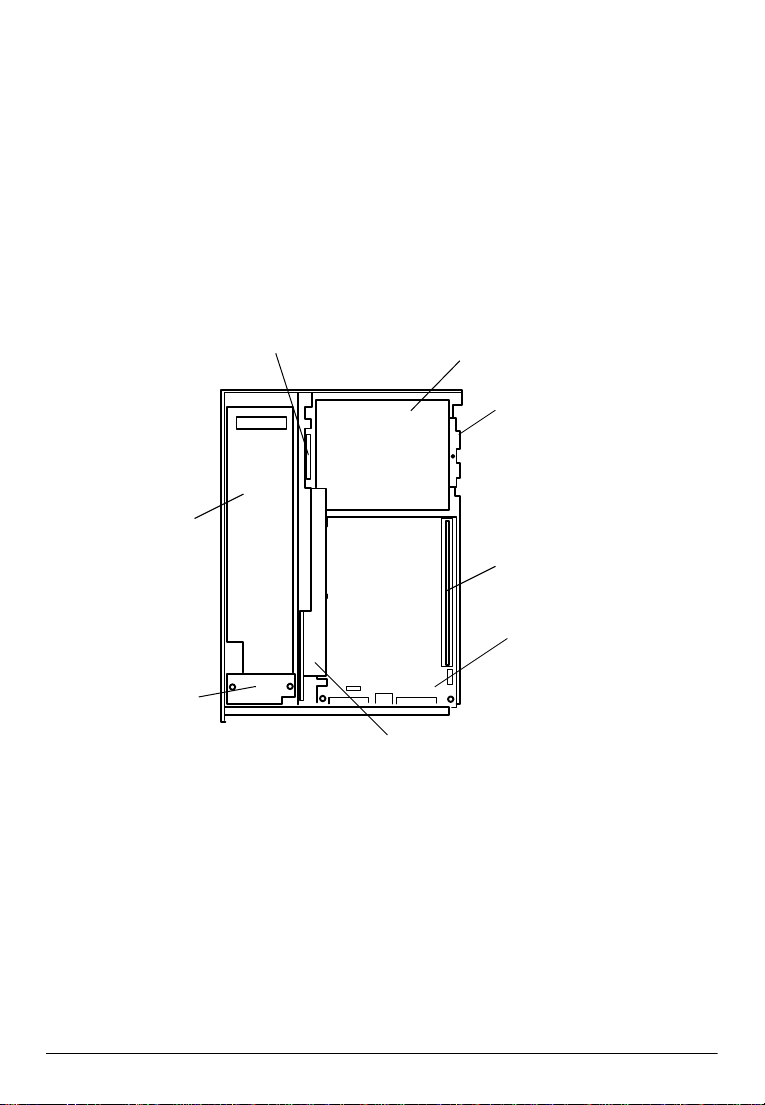
Locating Components
The following illustration shows the major components in the IM
module. As you install components, refer to this diagram to locate
the ones you need.
Floppy disk drive
connector
Power board
Floppy disk drive
Hard disk drive
(under floppy disk drive)
SIMM socket
Modular board
System board
Connector board
Installation 1-11
Page 28
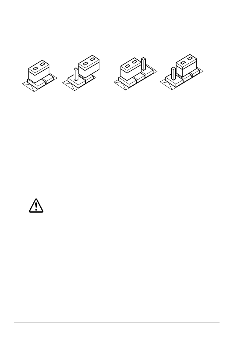
Setting the Jumpers
The IM module contains three circuit boards with jumpers you can
set to control how the system operates. The following sections
describe setting the jumpers on each of these boards.
3
On
2-pin jumper 3-pin jumper
Off
1
1-2
1
3
2-3
For two-pin jumpers, the jumper is either on (it connects the two
pins) or off (it doesn’t connect the two pins).
For three-pin jumpers, the jumper setting is 1-2 when the jumper
connects pins 1 and 2. The setting is 2-3 when pins 2 and 3 are
connected. You see a 1 and a 3 printed on the circuit board to
identify these pins.
To move a jumper from one position to another, use needle-nose
pliers or tweezers to pull it off the pins and move it to the desired
position.
Caution
Be careful not to bend the jumper pins or damage any
components on the board.
1-12 Installation
Page 29
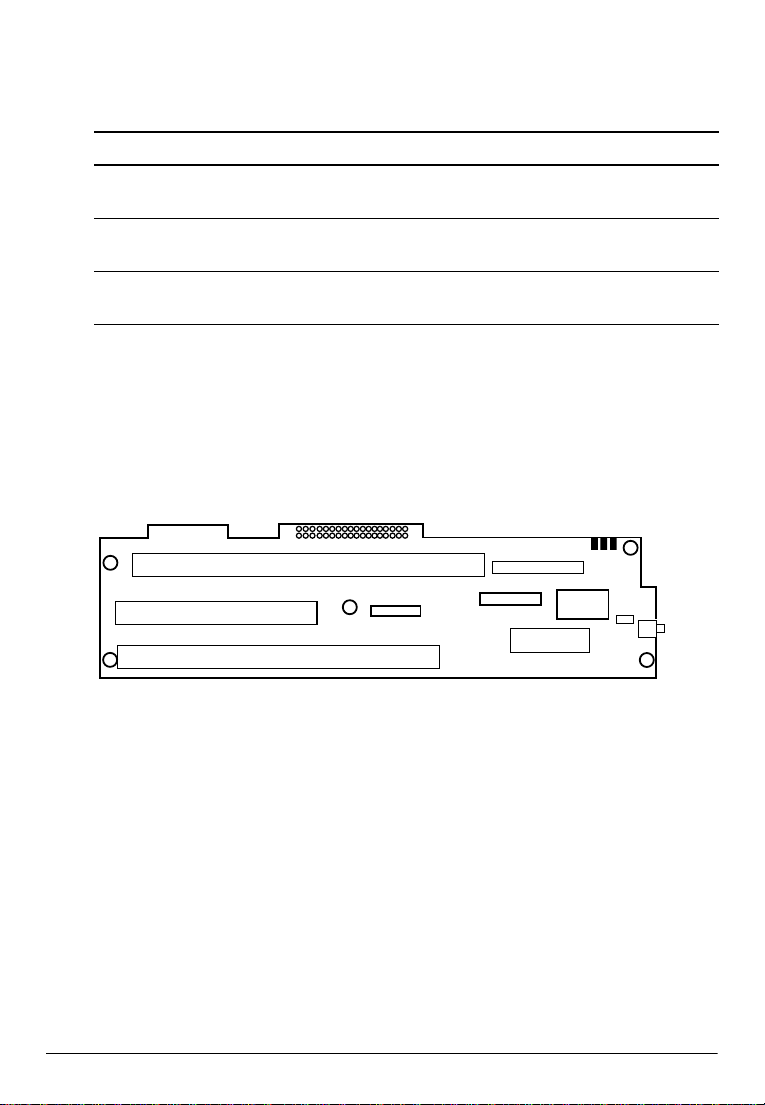
System board jumper settings
The system board contains three sets of jumpers. Two jumpers
control the voltages for the SIMM and COM2. A third jumper
controls bank configurations for the SIMM.
The diagram below shows the location of the jumpers on the
system board.
JP2
13
1
CN3
JP3
JP3
CN3
JP2
3
CN2
CN2
1
1
3
3
CN4
CN4
JP1
CN1
CN1
JP1
13
1
JP4
12
3
If an ISA card or a PCMCIA expansion module is installed in the
IM module, remove it so that you can access the jumpers on the
system board. (See pages 1-26 and 1-29 for more information.) You
may also need to remove the SIMM if you cannot easily change the
setting for jumper JP1. (See page 1-18.)
Installation 1-13
Page 30
Use the information in the following table to change the jumpers on
the system board.
System board jumper settings
Jumper Position Function
JP1 1-2*
2-3
JP2 1-2*
2-3
JP3 1-2
2-3*
**Default setting
Configures the system to access a single bank SIMM
Configures the system to access a dual bank SIMM
Configures the system for a +5 V SIMM
Configures the system for a +3.3 V SIMM
Defines the signal for pin 1 of COM2 as +5 V
Defines the signal for pin 1 of COM2 as DCD
Connector board jumper settings
The jumper on the connector board sets the handshake signals of
the COM1 port.
The location of the jumper on the connector board is shown below.
CN9
CN3
CN1
CN2
CN4
CN5
CN6
If you have an ISA card installed, you may need to remove it to
access the jumpers on this board. See page 1-30.
1-14 Installation
JP1
JP2
CN7
JP3
SW1
Page 31

Use the information in the following table to change the jumper on
the connector board.
Connector board jumper settings
Jumper Position Function
JP1 On*
Off
JP2 Off* Undefined (fixed to off)
JP3 Off* Undefined (fixed to off)
*Default settings
Handshake of COM1 is DTR/DSR and DM status (pin
5) of DM display is received through the CTS terminal
Handshake of COM1 is RTS/CTS and DM status (pin 5)
of DM display is received through the DSR terminal
Note:
The control unit does not have a TM printer reset signal. However,
you can reset the TM printer using an interface signal. (Note that
the TM printer reset can be disabled by the DIP switches of the TM
printer.) The source of the reset can be changed by the JP1 as listed
below.
Source of TM printer reset
Jumper Setting Effect
JP1 On
Off
DTR
RTS
Installation 1-15
Page 32

External I/O board jumper settings
The jumpers on the external I/O board control functions for the
ports on this board.
The location of the jumpers on the external I/O board are shown
below.
JP1
JP2
JP2
JP4
JP6
JP1
JP3
JP4
JP3
JP5
JP6
JP5
To access the jumpers on the external I/O board, remove the cover
plate as shown below:
Cover plate
External I/O board
1-16 Installation
Page 33

Use the information in the following table to change the jumpers on
the external I/O board.
Caution
Before you change the setting of JP6 to 1-2, make sure that
pin 21 of the parallel/OCIA port is not grounded.
External I/O board jumper settings
Jumper Position Function
JP1 1-2
2-3*
JP2 1-2
2-3*
JP3 1-2
2-3*
JP4 1-2
2-3*
JP5 1-2
2-3*
JP6 1-2
2-3*
Defines the signal for pin 1 of COM3 as +5 V
Defines the signal for pin 1 of COM3 as DCD
Defines the signal for pin 1 of COM4 as +5 V
Defines the signal for pin 1 of COM4 as DCD
Enables the OCIA function (LPT2)
Disables the OCIA function (LPT2)
Disables COM4
Enables COM4
Disables COM3
Enables COM3
Defines pin 21 of LPT1 as OCIA return
Defines pin 21 of LPT1 as NC
*Default settings
Installation 1-17
Page 34
Installing or Removing a SIMM
The system board contains a single SIMM socket that can contain
one SIMM. The SIMM must meet the specifications in Appendix B.
Caution
To avoid generating static electricity and damaging the
SIMM, ground yourself by touching a grounded metal surface
before you touch the SIMM.
Follow these steps to install the SIMM:
1. If an ISA card is blocking the SIMM, remove it.
Caution
To avoid contamination, do not touch the connectors on
the SIMM.
2. Position the SIMM at an angle over the socket. The notch on the
SIMM points toward the floppy disk drive, as shown below:
3. Push the SIMM into the socket until it is seated firmly.
1-18 Installation
Page 35

4. Tilt the SIMM until it is upright, guiding the hole at each end of
the SIMM over the retaining post at each end of the SIMM
socket. If it does not go in smoothly, do not force it; pull it all
the way out and try again.
Caution
Make sure the SIMM is properly installed and locked by the
tabs on both sides of the socket.
Tabs
5. If you removed an ISA card, replace it.
Note:
After you have installed the SIMM, make sure the jumper settings
are correct for the type of SIMM you installed (page 1-14); then run
the System Configuration Utility to set the parity for a 32-bit or
36-bit SIMM.
When you want to remove the SIMM, use your fingers or a small
screwdriver to carefully pull away the metal tabs that secure the
SIMM at each end. The SIMM falls to the side. Lift it out of the
socket. Make sure you store the SIMM in an anti-static bag.
Installation 1-19
Page 36

Installing a Hard Disk Drive
You can install a 2.5-inch hard disk drive (0.5 inch high) in the
IM module. EPSON-supplied drives come with the necessary
mounting bracket and adapter.
Caution
Handle the hard disk drive gently. Small shocks or vibrations
could damage the drive.
Note:
You do not need to remove an installed floppy disk drive before you
install the hard disk drive in the IM module. The hard disk drive
assembly slides under the floppy disk drive.
Follow these steps to install this hard disk drive assembly:
1. Locate the tabs on the bottom of the chassis.
Caution
To avoid contamination, do not touch the drive
connectors.
2. Slide the drive assembly into the chassis so that the notches
along the bottom of the assembly are under the chassis tabs.
1-20 Installation
Tabs
Page 37

3. Push the drive assembly in gently until you feel the connector
fit into place.
4. Secure the mounting bracket to the IM module with the
retaining screw, as shown below.
Tab
Note:
After you have installed a hard disk drive, run the System
Configuration Utility and use the hard disk drive auto-sensing
feature to set the hard disk drive type.
To remove the hard disk drive, remove the screw that secures the
mounting bracket to the IM module chassis. Then pull the hard
disk drive straight out of the chassis. The tabs at the end of the
bracket provide a convenient place for you to place your fingers
when you pull the hard disk drive assembly out.
Installation 1-21
Page 38

Installing a Floppy Disk Drive
You can install a 3.5-inch floppy disk drive in the IM module.
EPSON-supplied drives come with the necessary mounting bracket
and ribbon cable.
Follow these steps to install the floppy disk drive assembly:
1. If necessary, remove the slot cover at the front of the IM
module. Remove the screw securing the slot cover to the
chassis, as shown below; then lift the slot cover out and replace
the screw to secure the LED board again. Store the slot cover in
case you remove the floppy disk drive later.
LED board
2. If a SIMM is installed in the control unit, remove it. (See page
1-18.)
1-22 Installation
Page 39

3. Slide the floppy disk drive assembly as far as it will go to the
front of the IM module.
4. Then move the drive toward the connector board until the two
tabs on the floppy disk drive mounting bracket slide into the
corresponding slots in the connector board and chassis. (If you
look at the area from the other side of the chassis partition, you
can see the tabs as they come through the slots.) You should
feel the two locator pins on the mounting bracket fit into the
corresponding holes in the chassis.
Installation 1-23
Page 40

5. Hold the drive assembly in place as you secure it to the chassis.
6. Locate the connector for the floppy disk drive ribbon cable.
7. Gently pull both ends of the connector toward you until you
can see a slit in the connector. You may need to use a small
screwdriver or a pair of tweezers to pull out the left side.
Caution
To avoid contamination, do not touch the cable
connector.
8. Insert the ribbon cable all the way into the slit.
1-24 Installation
Page 41

9. Hold the ribbon cable firmly in the connector and push in the
ends of the connector. You may need to use a small screwdriver
or tweezers to push in the left side of the connector.
10. If you removed a SIMM, reinstall it. (See page 1-18.)
Note:
After you have installed a floppy disk drive, run the System
Configuration Utility and use the Disk ette Drive option to set
the size of the drive.
To remove the floppy disk drive, reverse the steps above.
Installation 1-25
Page 42
Installing a PCMCIA Expansion Module (option)
You can install an optional PCMCIA expansion module in the
middle slot on the connector board. (The system board occupies the
bottom slot.) The PCMCIA expansion module can support two
Type I or Type II cards or a single Type III card.
1. If a SIMM is installed in the IM module, remove it. (See page 1-18.)
2. Remove the retaining screw securing the slot cover to the IM
module, as shown below. (Keep the screw to secure the
PCMCIA expansion module to the control unit.)
3. Slide the slot cover out and set it aside. Store the slot cover in
case you remove the PCMCIA expansion module later.
1-26 Installation
Page 43

4. Push both sides of the PCMCIA slot cover inside the cover, and
remove it.
Caution
To avoid contamination, do not touch the connectors on
the PCMCIA expansion module.
5. Hold the PCMCIA expansion module along the top corners
and guide it into the connector, as shown below:
Connector
PCMCIA
expansion
module
Installation 1-27
Page 44

Once the connectors on the PCMCIA expansion module reach
the slot, push them in firmly (but carefully). You should feel
them fit into place. If the expansion module does not go in
smoothly, do not force it; pull it all the way out and try again.
6. Secure the end of the PCMCIA expansion module to the IM
module with the retaining screw.
7. Find the PCMCIA slot cover you removed in step 4.
8. Insert the tab on one side of the PCMCIA slot cover into the
notch on the PCMCIA expansion module; then push the tab on
the other side into place.
Notches
Tabs
Caution
When you connect the PC card(s), make sure the drawing
current of the card(s) does not exceed the capacity limits
shown in Appendix A.
Note:
You need to remove the PCMCIA slot cover before you install or
remove the PC cards.
Caution
Make sure you always attach the slot cover to the PCMCIA
expansion module. The slot cover discharges the static electricity in
your body. If you do not attach the cover, the control unit could lock
up when you insert or remove the PC cards.
1-28 Installation
Page 45
9. If you removed a SIMM, replace it.
Note:
You need to install card and socket services software on your control
unit before it can recognize PC cards in the slots on the PCMCIA
expansion module. See the documentation provided with the module.
If you want to remove the PCMCIA expansion module, remove the
slot cover, remove the SIMM installed in the control unit, then remove
the retaining screw securing the PCMCIA expansion module to the IM
module. Pull the expansion module straight out of the slot and replace
the slot cover. Make sure you replace the SIMM.
Installing an ISA Card
You can install an ISA card in the ISA expansion slot on the
connector board. For the size of the card, see Appendix A.
Caution
When you connect the ISA card, make sure the drawing
current of the card does not exceed the capacity limits
shown in Appendix A.
1. If a SIMM is installed in the IM module, you may want to
remove it so you can access the ISA card slot more easily. (See
page 1-18.)
2. Remove the retaining screw securing the top slot cover, as shown
below. (Keep the screw to secure the ISA card to the IM module.)
Installation 1-29
Page 46

3. Slide the slot cover out and set it aside. Store the slot cover in
case you remove the ISA card later.
Caution
To avoid contamination, do not touch the card connectors.
4. Hold the card along the top corners and guide it into the
connector, as shown below:
Connector
ISA card
Once the connectors reach the slot, push the card in firmly (but
carefully) to insert it fully. You should feel the connectors fit
into place. If the card does not go in smoothly, do not force it;
pull it all the way out and try again.
5. Secure the end of the ISA card to the IM module with the
retaining screw.
6. If you removed a SIMM, replace it. (See page 1-18.)
If you want to remove the ISA card, remove the SIMM, then
remove the retaining screw securing the card. Pull the card straight
out of the slot, then replace the slot cover and the SIMM.
1-30 Installation
Page 47

Installing the Battery Pack (option)
Installieren der Batterie-Einheit (option)
Installation de la batterie (proposée en option)
The optional battery pack contains a Nickel-Cadmium (Ni-Cd)
battery. When there is a power failure, the battery supplies power
to the control unit for about a minute, which allows you to save any
transactions in progress. Follow these steps to install the battery
pack:
Die optionale Batterie-Einheit enthält eine Nickel-Cadmium (NiCd) Batterie. Bei einem Stromausfall, versorgt die Batterie die
Steuereinheit ca. eine Minute lang mit Strom, damit Sie
gegenwärtig ablaufende Vorgänge speichem können. Führen Sie
zur Installation der Batterie-Einheit die folgenden Schritte durch:
La batterie proposée en option contient un accumulateur NickelCadmium (Ni-Cd). Lorsqu’il y a une coupure de courant, la
batterie alimente l’ordinateur pendant environ une minute,
permettant ainsi de sauvegarder les opérations en cours. Suivre les
étapes suivantes pour installer la batterie:
1. Remove the IM module from the plastic housing. (See page
1-5.)
Nehmem Sie das IM-Modul aus dem Plastikgehäuse. (Siehe
Seite 1-5.)
Retirer le module IM du boîtier plastique. (Voir page 1-5.)
Note:
You can install the battery pack without removing the IM
module from the plastic housing. It is easier to install the battery
pack, however, when the IM module is not in the housing.
Installation 1-31
Page 48

Hinweis:
Sie können die Batterie-Einheit auch installieren, ohne das IMModul aus dem Plastikgehäuse herauszunehmen. Die BatterieEinheit läßt sich allerdings leichter installieren, wenn sich das
IM-Modul nicht im Gehäuse befindet.
Remarque:
Il est possible d’installer la batterie sans retirer le module IM de
son habitacle plastique. Il est, toutefois, plus facile d’installer la
batterire lorsque le module IM n’est pas dans le boîtier.
2. Use a coin or a flat head screwdriver to loosen the screw
securing the battery cover. (You cannot remove the screw
completely.)
Lockern Sie mit einer Münze oder einem Schraubenzieher die
Schraube, die die Batterieabdeckung festhält. (Die Schraube
kann nicht völlig entfernt werden.)
Utiliser une pièce de monnaie ou un tournevis plat pour
desserrer la vis du couvercle de la batterie (il n’est pas possible
de retirer complètement la vis).
3. Lift the side of the battery cover containing the screw away
from the IM module; then pull the tab out of the slot, as shown
below:
Heben Sie den Teil der Batterieabdeckung, auf dem sich die
Schraube befindet, vom IM-Modul ab und ziehen Sie
anschließend, wie unten abgebildet, den Führungsstift aus dem
Schlitz heraus.
1-32 Installation
Page 49

Soulever le côté du couvercle de la batterie contenant la vis du
module IM, puis retirer la languette de la fente tel qu’indiqué
ci-dessous.
Tab
ü
Führungsstift
Languette
Slot
Schacht
Fente
4. If it is the first time to install the battery, disconnect the dummy
connector from the IM module.
Wenn die Batterie zum ersten Mal installiert wird, ziechen Sie
den Blindstecker vom IM-Module ab.
Si c’est la première fois que l’on installe la batterie, détacher le
connecteur factice du module IM.
Dummy connector
Blindstecker
Connecteur factice
Installation 1-33
Page 50

5. Locate the connector on the battery pack.
Machen Sie den Anschlußstecker der Batterie-Einheit
ausfindig.
Localiser le connecteur sur la batterie.
6. Align the tab in the casing of the battery connector with the
notch in the socket on the IM module; then insert the connector
in the socket.
Richten Sie den Führungsstift am Gehäuse des Batteriesteckers
an der Aussparung in der Anschlußbuchse des IM-Moduls aus.
Stecken Sie anschließend den Stecker in die Buchse.
Verifier que le détrompeur de la fiche de la batterie est bien
positionné par rapport au connecteur du module IM, puis
insérer la fiche dans le connecteur.
Connector
Stecker
Fiche
Socket
Anschlußbuchse
Connecteur
7. Slide the battery pack into the compartment.
Schieben Sie die Batterie-Einheit ins Fach.
Glisser la batterie dans le compartiment.
1-34 Installation
Page 51
8. Replace the battery cover by sliding the tab into the slot and
lowering the cover over the battery.
Bringen Sie die Abdeckung wieder an, indem Sie den
Führungsstift in den Schlitz einschieben und die Abdeckung
auf die Batterie absenken.
Remettre le couvercle de la batterie en glissant la languette
dans la fente et en baissant le couvercle sur la batterie.
Caution
Be careful the battery cable is not caught between the
battery cover and the chassis as you replace the cover.
Achtung
Achten Sie darauf, daß beim Anbringen der Abdeckung
das Batteriekabel nicht zwischen der Batterieabdeckung
und dem Gehäuse eingeklemmt wird.
Précaution
Faire attention à ne pas coincer le câble entre le
couvercle de la batterie et le chassis lorsque l’on remettra
le couvercle en place.
9. Secure the battery cover to the IM module by tightening the
screw.
Befestigen Sie die Batterieabdeckung am IM-Modul, indem Sie
die Schraube anziehen.
Visser le couvercle de la batterie au module IM en serrant la
vis.
Installation 1-35
Page 52

10. Return the IM module to the plastic housing.
Setzen Sie das IM-Modul wieder in das Plastikgehäuse ein.
Remettre le module IM dans le boîtier plastique.
Leave the control unit on for 48 hours for full charging.
Lassen Sie den Control unit zum vollständigen Aufladen 48
Stunden eingeschaltet.
Laisser l’ordinateur sous tension pendant environ 48 heures pour
une charge complète.
To remove the battery pack, reverse the steps above.
Zum Entfernen der Batterie-Einheit die obigen Schritte in
umgekehrter Reihenfolge ausführen.
Pour retirer la batterie, refaire les étapes précédentes en sens
inverse.
Setting Up the Control Unit
Connecting the TM printer
This section describes how to connect the TM printer to the control
unit.
For setting up the TM printer itself, see the operator’s manual for
the TM printer.
Follow these steps to connect the TM printer:
1. Remove the IM module from the plastic housing. (See page 1-5.)
2. Connect the power cable and interface cable to the IM module.
For the interface cable, tighten the screws on both sides of the
cable connector.
1-36 Installation
Page 53

Note:
You need an appropriate interface cable. The interface cable is not
enclosed with your control unit box.
Screws
Interface
cable
TM power cable
3. Form the power cable and interface cable as shown below then
lock them by two clips on the IM module.
Clips
Installation 1-37
Page 54
4. Replace the IM module into the plastic housing.
Caution
Be careful the cables are not caught between the
housing and the IM module.
Caution
Make sure you lock the IM module to the plastic housing
using the lock on the front panel. The module could fall
from the housing if it isn’t secured.
1-38 Installation
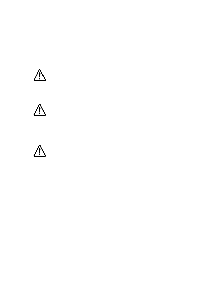
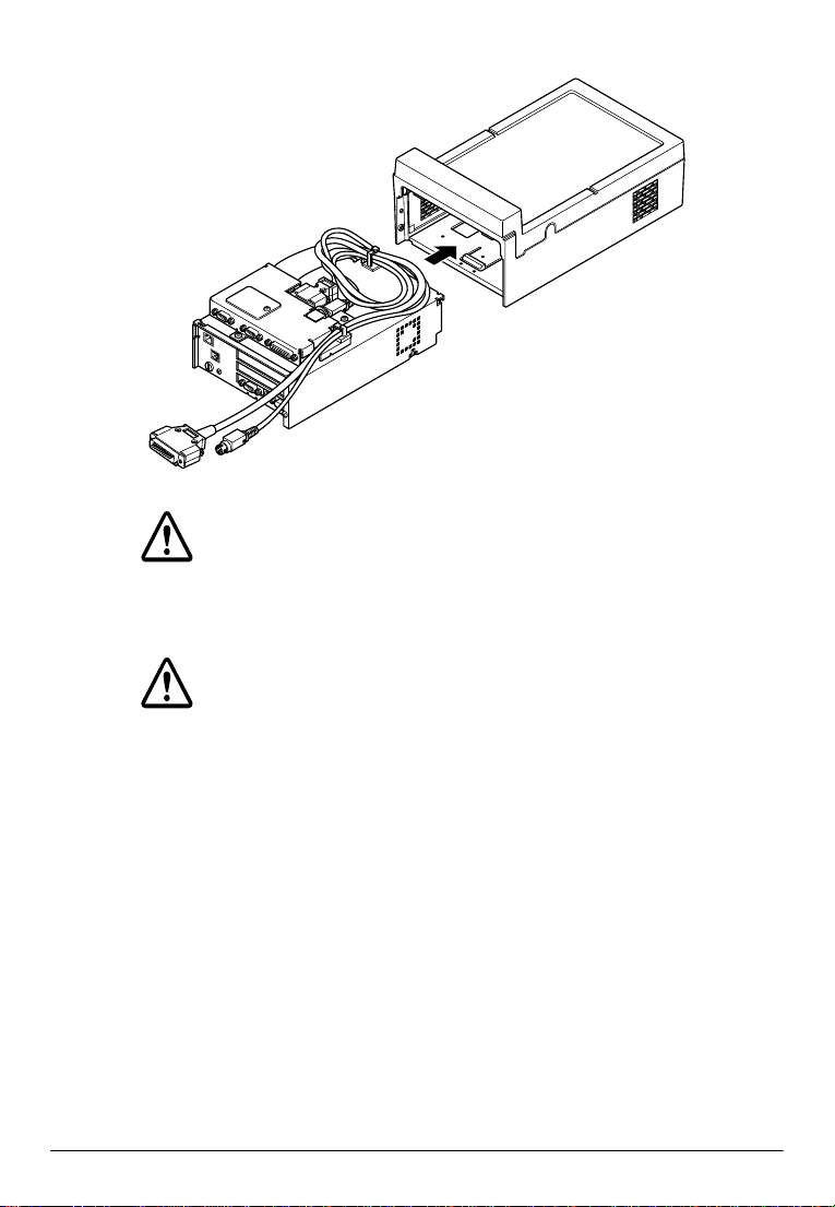
Page 55

5. Lead the power and interface cables into the hole on the back of
the plastic housing.
6. Connect the power and interface cables to the TM printer
referring to the operator’s manual of the TM printer.
7. Set the TM printer on the control unit.
TM printer
Control unit
Connecting Peripherals
You can connect various peripherals to the control unit using the
connectors on the back panel.
Installation 1-39
Page 56

Caution
See Appendix A for power limitations for any device that
draws its power from the control unit.
24 VDC
connector
Note:
For some peripherals, you may need to change the jumper settings.
See page 1-12 for more information.
Caution
Never plug a telephone line into the DM display port.
Connecting the Power Supply
The power supply that came with the control unit contains a DC
cable connector that connects to the 24 VDC connector on the back
panel of the control unit. Follow these steps to connect the power
supply:
1. Unpack the power supply. Make sure you read the safety
instruction sheet that came with the power supply.
1-40 Installation
Page 57

2. Connect the DC cable connector of the power supply to the 24
VDC connector on the control unit. Push the connector in as far
as it will go.
24 VDC
connector
3. Insert the power cord into an electrical outlet.
See Appendix A for additional information on the power supply.
Installation 1-41
Page 58

Attaching the Back Cover
The control unit comes with a back cover that provides a protective
covering for your cables. After you have connected all the
peripherals to the control unit, attach the back cover. Insert the tabs
on one side of the cover first; then push the tabs on the other side
into place.
Back cover
Caution
Never lift the control unit by the back cover. This cover
cannot support the weight of the control unit, so it could
drop.
Setting a Password for the Drawer Kick-out Test
If you plan to use a drawer, you must set a password for accessing
the drawer kickout test in the device diagnostics utility.
Caution
Make sure you always set a password. The drawer kickout test
checks whether the cash drawer opens correctly. Anyone can
access the test, however, if you do not define a password.
1-42 Installation
Page 59

To set a password see Chapter 2.
Charging the Batteries
Lithium Battery
The control unit contains a rechargeable Lithium battery that backs
up the real-time clock and the CMOS RAM data. The Lithium
battery is not charged fully at the factory. You need to charge the
battery before you use the control unit for the first time. If you
replaced the battery or you have not used the control unit for a long
time, you still need to charge it.
Follow these steps to charge the battery:
Caution
Charge the Lithium battery before you first use the control
unit. If the Lithium battery is not fully charged, your system
configuration settings in the CMOS RAM may be incorrect
when you start the control unit.
1. Connect the power supply to the control unit.
2. Turn on the power switch of the control unit. The Lithium
battery is charged when the power LED light is on.
The Lithium battery is being charged when the control unit is being
turned on. Use the following table for time of charging.
Time for full charge 40 hours or more (from factory condition)
Backup time 30 days or more (with full charge)
Installation 1-43
Page 60

Ni-Cd Battery (option)
The optional rechargeable Nickel-Cadmium (Ni-Cd) battery
provides power to the control unit for about a minute in the event
of a power failure. The Ni-Cd battery is not charged fully at the
factory. You need to charge the battery before you use the control
unit. If you have already replaced the battery or you have not used
the control unit for a long time, you still need to charge it. Follow
these steps to charge the battery:
Caution
Charge the Ni-Cd battery before you use the control unit. If
the Ni-Cd battery is not fully charged, it may not be able to
provide power to the control unit for a full minute.
1. Connect the power supply to the control unit.
2. Turn on the power switch of the control unit. The Ni-Cd
battery is charged when the power LED light is in green.
The Ni-Cd battery is being charged when the control unit is being
turned on. Use the following table for time of charging.
Time for full charge 48 hours or more (from factory condition)
Backup time 1 minute (with full charge)
1-44 Installation
Page 61

Chapter 2
Using System Utilities
The control unit comes with the following utility programs in the
System ROM:
❏ System Configuration Utility, for defining the configuration of
the system.
❏ Power management, for establishing power management
criteria.
❏ Device Diagnostics, for troubleshooting devices attached to the
control unit.
You can access the system configuration and power management
utilities directly from DOS or from some other application that
doesn’t control keyboard input. You can also access the power
management utility from within the System Configuration Utility.
You see a prompt to access Device Diagnostics each time you start
the control unit.
These programs and the factory default options for this control unit
are stored in the ROM. New configuration settings are stored in
CMOS RAM, which is backed up by a battery.
Using the System Configuration Utility
The System Configuration Utility defines how the system is
configured. You need to run this program the first time you
configure the control unit. You may need to run it again if you
change the configuration.
Using System Utilities 2-1
Page 62

Note:
If, for any reason, you remove the system board from the IM module,
you must run the System Configuration Utility to redefine your
configuration.
The System Configuration Utility lets you verify or change the
following:
❏ Standard settings such as date, time, COM port addresses, LPT
port addresses, LPT port mode, floppy disk drive type, hard
disk drive type, and video display
❏ Preferences, such as quick boot, Num Lock settings, CPU (boot)
speed, keystroke settings, passwords, enabling internal hard
disk and floppy disk drive controllers, and enabling keyboard
check.
❏ Memory options, such as shadowing system or video BIOS,
enabling cache, and enabling parity checking for the SIMM.
Starting the System Configuration Utility
You can run the System Configuration Utility by pressing Ctrl Alt S
from DOS or from an application program that does not control
keyboard input.
Caution
When you exit the System Configuration Utility, the system
reboots. Make sure you have saved any data before you
start the utility.
If, during the power-on self test, the system detects an error in your
system configuration, you see an error message on the screen,
followed by this message:
<CTRL-ALT-S> to enter System Configuration Utility,
<CTRL-ALT-P> to enter PM Configuration Util ity,
Press F1 to Continue
2-2 Using System Utilities
Page 63

Press Ctrl Alt S to run the System Configuration Utility and correct
the configuration information.
Changing Options in the System Configuration Utility
The System Configuration Utility uses a series of menu bars, pulldown menus, and dialog boxes to let you change settings. Follow
these guidelines for using the System Configuration Utility
program:
❏ To display a pull-down menu, use the left and right arrow keys
or press the key that corresponds to the highlighted letter in the
title. (Some options, like PowerMgmt, do not have a pull-down
menu.) Select the option and then press Enter to perform the
function or access the selection screen.
❏ To select an option from the pull-down menus, use the up and
down arrow keys to highlight the option; then press Enter to
select it. If additional options are available, you see a dialog
box. If no additional options are available, you see a check
beside the selected options.
❏ To select an item in a dialog box, use the up and down arrow
keys to highlight the option, then press Enter to select it. You
see an X beside the selected option.
❏ Press Esc to close a pull-down menu or leave a dialog box.
Setting the Date and Time
The real-time clock in the control unit continuously tracks the date
and time—even when the control unit is turned off. Once you set
these options, you shouldn’t have to set them again, unless you
adjust the time for daylight savings or a different time zone. (The
control unit automatically changes the date for leap years.)
To change the date, select the Date option from the Standard pulldown menu. Enter the new date in month/day/year format (use
the arrow keys to move between fields); then press Enter.
Using System Utilities 2-3
Page 64

To change the time, select the Time option from the Standard pulldown menu. Enter the new time in hours:minutes:seconds format
(use the arrow keys to move between fields); then press Enter. Use
a 24 hour clock to set this time. For example, 5 p.m. is 17.
Setting the COM Ports
You can disable the COM ports, COM port A (the connector
indicated as COM1 on the control unit) and COM port B (the
connector indicated as COM2 on the control unit), using the COM
Port option on the Standard pull-down menu. Select the COM
port you want to assign. The dialog box allows you to select from
these options:
❏ COM1 (3F8h)
❏ COM2 (2F8h)
❏ Disable.
Addresses for COM3 and COM4 are fixed at 3E8h and 2E8h,
respectively.
Setting the LPT Port Address
You can enable or disable LPT1 using the LPT Port Address
option on the Standard pull-down menu. When you select the
option, a dialog box allows you to select one of these options:
❏ LPT1 (378h)
❏ Disable.
Setting the LPT Port MODE Option
You can define the LPT1 port as one of the following interfaces
using the LPT Port MODE option on the Standard pull-down
menu.
❏ Printer
❏ Bi-directional
2-4 Using System Utilities
Page 65

If you want to set the LPT1 port as a unidirectional interface, select
Printer.
Setting the Floppy Disk Drive
You can set the size of your floppy disk drive using the Diskette
Drive option on the Standard pull-down menu. When you select
the option, you see a dialog box that allows you to select the size of
the drive. Set Drive A to 1.44MB and set Drive B to None.
Setting the Hard Disk Drive
Your control unit comes with a hard disk auto-sensing feature that
allows it to detect the type of hard disk drive you have installed.
When you select the Hard Disk 1 option from the Standard pulldown menu, you can choose from the following options:
❏ Standard
❏ Custom
❏ Auto
❏ None.
Select Auto to have the system automatically supply the correct
hard disk drive parameters for your drive.
Note:
When you select Standard, you see a hard disk drive table. Do not
select a drive type from this table. Use Auto or define a custom
drive.
If none of the parameters in the table match your drive, you need to
define your own drive type. Select Custom; then type the correct
value in each field. Press the down arrow key to move the cursor to
the next field.
Using System Utilities 2-5
Page 66

The following table describes the logical parameter you need to
enter in each field. When you have finished entering values, press
Enter.
Drive type options
Field Description
Cyls Number of cylinders
Heads Number of read/write heads
SPT Sectors per track the drive uses
Lzone Landing zone (the area on which the control unit parks the
Precomp Precompensation cylinder
heads)
If you have no hard disk drive installed, select None.
Note:
Always set the Hard Disk 2 option to None.
Setting the Video Display Type
The Standard pull-down menu lets you define the type of display
you have attached to the built-in VGA port. Although the screen
displays several options, the only option available for the control
unit is VGA Display.
Setting the Quick Boot Option
When you select the Quick Boot option from the Preferences
pull-down menu, the system doesn’t test memory during the
power-on self test. When the Quick Boot option is not selected,
the system performs a more comprehensive test of the hardware
and, as a result, takes longer to start. Use the up and down arrow
keys to highlight the Quick Boot option and press Enter. When
the option is selected, you see a check mark beside it.
2-6 Using System Utilities
Page 67

Setting the Num Lock Option
You can determine the initial Num Lock status when the system is
turned on or reset by selecting the Num Lock option from the
Preferences pull-down menu. Use the up and down arrow keys to
highlight the Num Lo ck option and press Enter. When the option is
selected, you see a check mark beside it. Then when you start the
control unit, Num Lock is on.
Setting the Boot Speed (CPU Speed)
The Boot Speed option on the Preferences pull-down menu lets
you set the default CPU speed. When you select Fast Clock in
the dialog box, the CPU operates at 33 MHz. When you select Slow
Clock, the control unit simulates a 16.5 MHz processor to provide
compatibility with older application programs. Select Fast Clock
unless you are using an application program that requires the
slower speed.
Setting the Keyboard Options
The Preferences pull-down menu contains two options that allow
you to determine keyboard speed functions: Typematic Rate
and Typematic De lay.
The Typematic Rate option defines the rate at which the
keyboard repeats a character when you hold it down. You can
select options between 2 characters per second to 30 characters per
second.
The Typematic Delay option defines the interval from when you
start to hold a key down to when the system starts to repeat the
character. You can select options between 250 ms and 1000 ms.
Using System Utilities 2-7
Page 68

Setting Passwords
You can set passwords for both access to the system and access to
the System Configuration Utility using the Boot Password
option and the SCU Pass word option on the Preferences pull-
down menu.
Note:
If you set a password for the System Configuration Utility, you can
still access the power management utility without entering a
password by pressing Ctrl Alt P. You need to enter a password,
however, if you access the power management utility through the
System Configuration Utility.
Defining a password
Follow these steps to define a password:
1. Select the Boot Password option if you want to define a
password for accessing the system. Select the SCU Password
option if you want to define a password for accessing the
System Configuration Utility. You see the following message:
Enter 4 to 8 keystrokes
2. Type the password you want and press Enter. Make sure you
enter at least four alphanumeric characters. You then see this
message:
Re-Enter to Verify
3. Type the same password a second time and press Enter. You
see this message:
Entry IS Verified
Press Any Key To Continue
4. Press any key. The password option you selected from the
Preferences pull-down menu now displays a check mark
beside it.
2-8 Using System Utilities
Page 69

If you defined a boot password, you see the following message
when you start your system:
Enter your BOOT PASSWORD
If you defined a password for the System Configuration Utility,
you see the following message when you press Ctrl Alt S to start the
System Configuration Utility:
Enter your SETUP PASSWORD
Type the password and press Enter.
Deleting a password
Follow these steps to delete a password:
1. Select the password you want to delete from the Preferences
pull-down menu (either Boot Password or SCU Password).
You see this message:
Enter PASSWORD
2. Type your password and press Enter. You no longer see the
check mark beside the password option on the Preferences
pull-down menu, indicating that the option is now disabled.
If you want to change a password, you must delete it first, then
enter the new password as described above.
Enabling the On-board Controllers
The Internal FDC and the Internal IDE options on the
Preferences pull-down menu let you enable or disable the internal
controller for the floppy disk drive (FDC) or the hard disk drive
(IDE). The internal controller is enabled when a check mark
appears beside the option. Highlight the option and press Enter to
toggle the setting on or off.
When these options are disabled, the system uses a controller
inserted into the ISA slot.
Using System Utilities 2-9
Page 70

Checking the Keyboard
The Keyboard Check option in the Preferences pull-down menu
lets you enable or disable the keyboard check during the power-on
self test. The keyboard check is enabled when a check mark
appears beside the option. Highlight the option and press Enter to
toggle the setting on or off.
Note:
If your system does not have a keyboard, always set the option to
disable.
Setting Memory Options
Memory values are displayed on the main System Configuration
Utility screen. You can enable or disable the following options on
the Memory pull-down menu:
❏ Shadow System BIOS
❏ Shadow Video BIOS
❏ Cache Enable
❏ Parity Check Enable.
When the Shadow System BIOS or the Shadow Video BIOS
options are selected, the system copies the contents of its system
and/or video BIOS into RAM, allowing the system to perform
certain operations faster. These options are enabled when you see a
check mark beside them.
You can enable or disable the 8KB of cache on your processor by
selecting the Cache Enable option. A check mark indicates that
the option is enabled.
The Parity Check Enab le option allows you to indicate
whether the SIMM you are using has parity (36-bit) or not (32-bit).
Enable this option if you are using a 36-bit SIMM.
2-10 Using System Utilities
Page 71

Exiting the System Configuration Utility
Select Exit from the menu bar then press Enter to leave the
System Configuration Utility. If you have changed settings, you see
the following message:
Do you wish to save your changes?
ESC to exit - ENTER to save and exit
Any other key to continue
Press Enter to save your changes and leave the utility or press Esc
to leave the utility without saving the changes you have made.
Press any other key to continue making changes.
If you select
following message:
Press Esc to leave the utility. Press any other key to continue
making changes.
Note:
When you exit the System Configuration Utility, the program
restarts the system, even if you have made no changes.
Exit
without changing any settings, you see the
ESC to exit now
Any other key to continue
Setting Power Management Options
The power management utility allows you to establish standby and
suspend criteria for the CPU, the hard disk drive, the VGA
controller, or a combination of these components. It also controls
the battery shutdown function.
You can start the power management utility from DOS or from an
application program that does not control keyboard input by
pressing Ctrl Alt P. You can also select the
the main System Configuration Utility menu and press Enter.
PowerMgmt
option from
Using System Utilities 2-11
Page 72

You see the MAXIMIZER™ power management screen. You can
select options and change settings from this screen just as you did
on the System Configuration Utility screen.
The MAXIMIZER screen provides the following pull-down menus
that allow you to set power management options:
❏ Controls
❏ System
❏ Device.
You can also select the Defaults option to select the power
management defaults and select Exit to leave the MAXIMIZER
screen.
Setting the Power Management Controls
When you display the Controls pull-down menu on the
MAXIMIZER screen, you see a single option, Power Savings.
When you select this option, you see a dialog box that allows you
to have the power management function operating at all times (the
Always option) or to disable the power management function (the
Disable option).
Note:
If this option is set to Disable, power management options are not
implemented, even if you have set specific options elsewhere on the
screen.
Your selection is displayed on the MAXIMIZER screen.
Defining System Power Management Criteria
The System pull-down menu contains the following options:
❏ CPU Standby
❏ Global Standby
2-12 Using System Utilities
Page 73

❏ Auto Suspend
❏ Video Monitoring.
These options determine how the system manages the power
management options.
You can enable or disable the CPU Standby option by
highlighting the option and pressing Enter. If this option is
enabled, the CPU enters a standby mode when the system has been
idle for 8 seconds. When the system enters CPU standby, the CPU
clock speed decreases from 33 MHz to 8.25.
When you select Global Standby from the System pull-down
menu, you see a dialog box that allows you to select the amount of
time required before the system enters a global standby mode.
When the CPU standby mode is enabled, the time interval set here
for the global standby begins when the system enters a CPU
standby mode (after 8 seconds). If the CPU standby mode is not
enabled, the time interval set here for the global standby begins
when the system detects an idle state.
In global standby, the system turns the hard disk drive motor off,
shuts the video output off (the VGA controller, however, remains
on), and reduces the CPU clock speed to 8.25 MHz. You can select
intervals between 1 minute and 16 minutes or you can disable the
global standby mode.
When you select Auto Suspend from the System pull-down
menu, you see a dialog box that allows you to select the interval of
inactivity required before the system enters a suspend mode.
Standby mode suspends activity for a subsystem, while a suspend
mode suspends activity for as much of the entire system as
possible, providing the highest level of power conservation. (The
CPU clock decreases to 0 MHz, the VGA controller enters a
suspend mode, the hard disk drive motor turns off, the I/O
controller turns off, and the AC power outlet turns off.) You can
select intervals between 1 minute and 30 minutes or you can
disable the automatic suspend mode.
Using System Utilities 2-13
Page 74

When you enable the Video Monitoring option by highlighting
the option and pressing Enter, you see a check mark beside the
option indicating that video monitoring is now enabled. When this
option is enabled, the system monitors the video display to control
whether video RAM access prevents the system from entering a
standby or a suspend mode. Also, when this option is enabled, a
system in a standby or suspend mode returns to an active mode
when video activity occurs.
Defining Device Power Management Criteria
Two power management options are available for specific
devices—the battery and the hard disk drive. When you select the
Battery Shutdown option from the Device pull-down menu,
you see a dialog box that allows you to select the interval before the
battery shuts down once a power failure has occurred.
Note:
When the Ni-Cd battery is not installed, this setting does not have
any meaning although it is settable.
Caution
Never set this option to Always On.
Set this option to 1 minute.
Note:
In some cases, you can set the Battery Shutdown option to up
to 5 minutes. The length of time the battery can actually provide
power depends on the following factors:
❏ The total amount of power load
❏ The age of the battery (battery capacity decreases throughout
the life of the battery)
❏ The temperature and humidity
❏ The current level of charge in the battery.
2-14 Using System Utilities
Page 75

Note:
When the control unit is powered from the Ni-Cd battery, the
battery supplies only +5 V current to the ISA expansion slot and
PCMCIA expansion module. An ISA card or PC cards using the
current such as +12 V are not supported during battery operation.
When you select the HardDisk Standby option from the Device
pull-down menu, you see a dialog box that allows you to select the
interval before the hard disk drive enters a standby mode (the
motor powers off). You can select Always On to keep the hard
disk drive running continually, or you can select an interval
between 1 and 16 minutes.
Exiting From the Power Management Utility
Select Exit from the menu bar then press Enter to leave the Power
Management Utility. If you have changed settings, you see the
following message:
Do you wish to save your changes?
ESC to exit - ENTER to save and exit
Any other key to continue
Press Enter to save your changes and leave the utility or press Esc
to leave the utility without saving the changes you have made.
Press any other key to continue making changes.
If you select Exit without changing any settings, you see the
following message:
ESC to exit now
Any other key to continue
Press Esc to leave the utility. Press any other key to continue
making changes.
The program returns you to the System Configuration Utility if
you accessed power management from there or to DOS (or an
application) if you accessed power management by pressing Ctrl
Alt P.
Using System Utilities 2-15
Page 76

Using Device Diagnostics
The Device Diagnostics utility included in the system ROM of the
control unit lets you isolate communication problems the control
unit or connected devices may be having. You can use these
diagnostics to test the following:
❏ TM printer operation test
❏ DM display indication test
❏ Cash drawer operation test
❏ Serial port loop-back test
❏ LPT1 port loop-back test
❏ OCIA port loop-back test
❏ Printing test of printer which is connected to LPT1
2-16 Using System Utilities
Page 77

Device Diagnostics Utility Conditions
The Device Diagnostics Utility runs under the following
conditions.
Table 2-1. Device Diagnostics Utility Conditions
Setting Condition
Connection to the TM printer The TM printer needs to be connected to the
Setting address of COM port A Set the address of COM port A to 3F8h, using
Setting of the TM printer
connection port
control unit. Connect the printer to either
COM1 ~ COM4 or LPT1 even if you will not
test the TM printer.
the System Configuration Unity.
Set the port which is connected to the TM
printer to be Enabled.
Set, using System Configuration Utility,
whether the TM printer is connected to
COM1, COM2 or LPT1.
Set jumper of external I/O board if the TM
printer is connected to COM3 or COM4.
Using System Utilities 2-17
Page 78

Table 2-1. Device Diagnostics Utility Conditions (Continued)
Setting Condition
Setting of the TM printer DIP
switches
DM display connector port Connect DM display to DM display port in
Setting of DIP switch of the DM
displays
Set the receiving buffer to maximum.
Set selection switch, which is the customer
display connection/non-connection, to nonconnection. (If it has a selection switch).
Set up the setting on communication to
follow the instruction, if the TM printer does
not have the ID function. (ESC/POG GSI
command).
Baud Rate: 9600 bps
Word Length: 8 bits
Parity: None
Refer to the manual of the TM printer for the
setting procedure.
IM-X40/IM-X41, when DM display is tested.
❏
When the TM printer connects to COM1.
Set up the setting on communication to
follow the instruction, when the TM printer
which has the ID function (ESC/POS GS I
command).
Baud Rate: Same setting as the TM printer
Word Length: Same setting as the TM
printer
Parity: Same setting as the TM printer
Set up the setting on communication to
follow the instruction, when the TM printer
which does not have the ID function (ESC/
POS GS I command).
Baud Rate: 9600 bps
Word Length: 8 bits
Parity: None
❏
When the TM printer connects another
port except COM1.
Set up the DM display the setting on
communication to follow the instruction.
Baud Rate: 9600 bps
Word Length: 8 bits
Parity: None
Refer to the DM display manual for the
setting procedures
2-18 Using System Utilities
Page 79

Starting Device Diagnostics
When you start either the control unit, you see the following
prompt for a few seconds.
Press F2 to start Device Diagnostics.
When you see the prompt, press F2. You see the following dialog
box when you start the Device Diagnostics Utility.
Select TM Port
COM1
COM2
COM3
COM4
LPT1
None
Select the port which is connected to the TM printer, using the up
or down arrow key; then press ENTER.
You see the Device Diagnostics screen.
Device Diagnostics uses a series of menu bars, pull-down menus,
and dialog boxes that allow you to select options or perform
diagnostic tests. Follow these guidelines for using Device
Diagnostics:
❏ To display a pull-down menu, use the left or right arrow key to
highlight the option; then press Enter (if necessary). You can
also see the pull-down menu if you press the key which
corresponds to the initial letter of the option. (The
Initialize option does not have a pull-down menu.)
❏ To select an option from the pull-down menus, use the up or
down arrow key to highlight the option; then press Enter. If the
option has a dialog box, you see it when you press Enter.
❏ Press Esc to close a pull-down menu or a dialog box.
❏ Press the back-space key to correct typing.
Using System Utilities 2-19
Page 80

Device Diagnostics Screen
The Device Diagnostics screen is divided into the following areas:
❏ TM/Drawer
❏ DM
❏ COM ports
❏ LPT1/OCIA
❏ Messages.
TM/Drawer
The TM/Drawer area of the Device Diagnostics screen displays the
communication settings, cash drawer driving pulse signal width
and the status for the TM printer and cash drawer.
Table 2-2. TM/DM information
Setting Description
TM model Displays the model name depending on the type of TM
TM port Displays the TM printer connection support which was
TM reset signal Indicates the signal and signal definition the control unit is
Baud rate Indicates the baud rate Device Diagnostics is using to
Word length Indicates the word length Device Diagnostics is using to
Parity Indicates whether Device Diagnostics is using parity to
Drawer On Time Displays the pulse width of signal for opening the cash
TM status Indicates the status of the TM printer. See the table called
Drawer Status Displays the status (High/Low) of the cash drawer.
printer attached to the control unit.
selected when you started the Device Diagnostics Utility.
using to reset the TM printer. You see
the control unit does not have a reset signal.
communicate with the TM printer and DM display.
communicate with the TM printer.
communicate with the TM printer.
drawer.
“TM status messages” for a description of these messages.
None
here because
2-20 Using System Utilities
Page 81

Table 2-3. TM status messages
Message Priority Description
Disable – The port, which is connected to the TM printer is
No communication
–
disabled. Set to Enabled using the System
Configuration Utility or jumpers on the External I/O
board.
❏
Displays this message when a TM printer that does
not have ID function (ESC/POS GS I command) is
connected. Check whether DIP switches of the
TM printer are set to the following.
Baud Rate: 9600 bps
Word Length: 8 bits
Parity: None
Although the screen indicates “No
communication,” the Device Diagnostics Utility
can communicate to the TM printer if the DIP
switches are set up correctly. If something is
wrong, check the TM status messages.
❏
Device Diagnostics Utility cannot communicate
to the TM printer when a TM printer that has ID
function (ESC/POS GS I command) is connected.
Check the following items:
❏
The interface cable and power cable is
connected properly to the TM printer.
❏
Make sure you turn off the control unit before
you connect the cable.
❏
The TM printer power switch is on.
❏
The TM printer, that was selected when
Device Diagnostics Utility started is connected
to the port.
❏
The TM printer is not performing a self-test
when Device Diagnostics Utility starts.
❏
A paper feed switch is not pressed when
Device Diagnostics Utility starts.
If the TM printer does not meet these conditions,
correct the problem and select the Initialize option
from the menu bar.
If the printer meets all the above conditions, one of
the following may have occurred:
❏
The print head has overheated.
❏
The TM printer is not working.
❏
The TM printer interface circuit on the control unit
is not working.
Using System Utilities 2-21
Page 82

Table 2-3. TM status messages (Continued)
Message Priority Description
Hardware
error
Paper feeding 2 The TM printer is feeding paper.
Receipt end 3 The receipt paper path contains no paper.
Journal end 4 The journal paper path contains no paper.
Paper nearend
Receipt nearend
Journal nearend
Cover open 8 The printer cover is open.
On-line 9 The printer is on-line. The TM print test is possible.
* If Device Diagnostics detects more than one TM status, it displays the
highest priority message. (Priority code 1 is higher than priority code 3.)
1 The print head is overheated, or the printer is not
working.
5 The paper roll diameter is too small or is not installed.
6 The receipt paper roll diameter is too small or is not
installed.
7 The journal paper roll diameter is too small or is not
installed.
DM
The DM area on the screen indicates the communication settings
and the status of the DM display.
Table 2-4. DM Information
Setting Description
DM port Indicates the port that the Device Diagnostics Utility
Baud Rate Indicates the Baud Rate that the Device Diagnostics
Word Length Indicates Word Length that the Device Diagnostics
Parity Indicates whether Device Diagnostics Utility uses
DM status Indicates DM status. Refers to Table 2-5, which has
uses to transmit data.
Utility uses to communicate to the DM display.
Utility uses to communicate to the DM display.
parity to communicate to DM display.
explanations of these messages.
2-22 Using System Utilities
Page 83

Table 2-5. DM status messages
Message Description
Disable COM port A is not set to 3F8h. Set COM port A to 3F8h in
No communication Device Diagnostics is not able to communicate with the
Busy DM display’s condition is busy. It is possibly caused by the
Ready The DM display is ready to receive data. The DM display
the System Configuration Utility.
DM display. Check the TM printer and DM display for the
following:
❏
The DM display is properly connected. Make sure you
turn off the control unit before you connect the
cable.
❏
The data communications DIP switch is the same for
the DM display and the TM printer. Make sure you
turn off the control unit before you change the
settings.
❏
DM display power switch is on.
❏
DM display is not executing a self test.
If DM display does not meet these conditions, correct the
problem and select the Initialize option from the menu
bar.
If the TM printer and DM display meet the above
conditions, one of the following may have occurred:
❏
DM display interface circuit on the control unit is not
working.
❏
The DM display is not working.
following;
❏
DM display is running a self test.
❏
After the Device Diagnostics Utility starts, the DM
display power was turned off.
test is possible.
COMM port information
The COM ports area of the screen lists the DTR, DSR, RTS, CTS,
DCD, and RI status for each of the available COM ports. When the
port is disabled, you see a message to that effect.
Using System Utilities 2-23
Page 84

LPT1/OCIA information
The LPT1/OCIA area of the screen lists the -BSY, -ACK, PE, SLCT,
and -ERR status for the LPT1 port, and the RDT, -CLI, SDT, and
-CLO status for the OCIA port. When the port is disabled, you see a
message to that effect.
Messages
The message portion of the screen displays the result of tests.
Table 2-6. Message area
Test category Message Description
TM printer Disable The port is disabled.
Done The TM printer test is completed. Check the
DM display test Disabled The port is disabled.
Done DM display test is completed. Check
Drawer kick-out
test
Loop-back test Error The diagnostics test failed. This message also
Disabled The port is disabled.
Done The Drawer kick-out test is completed. Check
Disabled The port is disabled.
printing motion and auto cutter motion.
indication.
the motion of cash drawer.
appears when a loop-back connector is not
connected or the wrong loop-back
connector is connected.
Ok The test completed successfully
LPT1 print test Time out The printer connected to the LPT1 port did not
enter a ready state after 2 seconds.
Disabled The port is disabled.
Ok The print data was sent successfully.
2-24 Using System Utilities
Page 85

Using the Setup Menu
The Setup menu allows you to create a password for accessing the
drawer kick-out test and to set the length of time for the voltage
signal supplied to the solenoid of the cash drawer to open it.
Defining a password
Follow these steps to define a password:
1. Select the Drawer Password option from the Setup pull-
down menu. You see the following message in a dialog box:
Enter
2. Type the password you want and press Enter. Passwords can
be 4 to 8 alphanumeric characters. Make sure you enter at least
four characters or numbers. You then see this message:
Re-Enter
3. Type the same password a second time and press Enter.
The password is now defined. You see the following prompt each
time you select the Drawer kick-out test from the Device-
Tests pull-down menu.
Enter
Type the password and press Enter to perform the drawer kick-out
test.
Changing or deleting a password
Follow these steps to change or delete a password.
1. Select the Drawer Password option from the Setup pull-
down menu. You see this message:
Old
Using System Utilities 2-25
Page 86

2. Type your current password and press Enter. You then see the
following message:
New
3. If you no longer want the password, press Enter. The password
is now deleted. If you want to define a new password, type the
new password and press Enter. You see this message:
Re-Enter
4. Type the same password a second time and press Enter.
Setting the Drawer ON time
The Drawer ON time option sets the length of time required for
the voltage signal to pass through the solenoid to open the cash
drawer.
To set the time, select the Drawer ON t ime option from the Setup
pull-down menu. You see a dialog box allowing you to enter the
ON time your cash drawer requires. You can enter a value up to
500 (ms). For the appropriate value, see your cash drawer manual.
Running Device Tests
The Device-Tests option on the menu bar allows you to run the
following tests:
❏ TM print test
❏ DM display test
❏ Drawer kick-out test
❏ COM1 loop-back test
❏ COM2 loop-back test
❏ COM3 loop-back test
2-26 Using System Utilities
Page 87

❏ COM4 loop-back test
❏ OCIA loop-back test
❏ LPT1 loop-back test
❏ LPT1 print test.
Note:
Before you perform the loop-back tests, you need to connect an
appropriate loop-back connector to the port. See Appendix A for the
loop-back connector configurations.
TM print test
The following tests are executed during the TM print test:
❏ Receipt print test, which prints a standard print pattern
❏ Auto cutter test (for the printer eqipped with an auto cutter
only)
Note:
Before you run the test, make sure the TM status message says online. If it doesn’t, see Table 2-3.
When the test is complete, make sure the standard print pattern
printed. For the printer which has an auto cutter, make sure that
the auto cutter cut the receipt.
DM display test
The DM display test sends the following message to the DM
display:
Display Module Test
***** Device Diagnostics *****
Using System Utilities 2-27
Page 88

Note:
Before you run the DM display test, make sure the DM status
message says Ready. If it doesn't, see Table 2-4.
Check the DM display screen to see if the test has been performed.
Drawer kick-out test
The drawer kick-out test opens the cash drawer. If the cash drawer
opens, the test was successful. The TM printer has two drawer
kick-out drive signals: signal 1 (pin 2) and signal 2 (pin 5).
However, this test checks only for the drawer kick-out drive
signal 1.
If you set a password for the drawer kick-out test (page 2-23), you
see the following prompt when you select Drawer kick-out
test from the menu bar:
Enter
Type your password and press Enter. Device Diagnostics tries to
open the cash drawer.
Note:
Before you run the drawer kick-out test, make sure the TM status
message says on-line. If it doesn't, see Table 2-3.
COM ports, OCIA, and LPT1 loop-back tests
The following loop-back tests are available:
❏ The COM port test checks the DTR, DSR, CTS, RTS, TXD, and
RXD signals.
❏ The LPT1 port test checks the -STROBE, -ACK, DATA0, BUSY,
-AUTO FEED, PAPER EMPTY, -ERR, -INIT, -SELECT IN, and
SELECT signals.
❏ The OCIA port test checks the -CLOCK OUT, -SDATA,
RETURN, -CLOCK IN, RDATA RETURN, and -RDATA
signals.
2-28 Using System Utilities
Page 89

Note:
Before you run these tests, make sure that the port you want to test
is enabled and that the appropriate loop-back connector is attached to
the port.
When the tests complete successfully, you see ok in the Message
area of the screen. If the test failed, you see an error message.
LPT1 print test
The LPT1 print test prints a standard print pattern on the printer
connected to LPT1. If the printer is busy, you see the time-out
message in the Message area of the screen.
Note:
Before you run the LPT1 print test, make sure the LPT1 port is
enabled. Also make sure that an appropriate printer is connected to
the LPT1 port.
Initializing Device Diagnostics
When you select Initialize from the menu bar, Device
Diagnostics restarts the program. If Device Diagnostics displays No
communicatio n for the TM status of TM/Drawer area or DM
status of DM area, fix the problem. Then select this option to reset
the program. See Table 2-3 and Table 2-4 for more information.
Leaving Device Diagnostics
When you select Exit from the menu bar, the system quits Device
Diagnostics and restarts the control unit.
Using System Utilities 2-29
Page 90

Chapter 3
Troubleshooting
The control unit has been designed with reliability in mind. If,
however, if you encounter any difficulties using this control unit,
read this chapter. The first section provides error messages and
beep codes for diagnostics the system runs during the power-on
self test (POST). This section is followed by some general
troubleshooting guidelines for the system.
If the control unit still does not work correctly, you can use the
following built-in diagnostic aid to help isolate the problem:
❏ POST codes: the system sends error codes to Port 80h, which
you can see when you have installed a Port 80 card in the ISA
slot. (See page 3-13.)
Error Handling
If the BIOS detects an error, you see or hear one of the following:
❏ WARNING messages state where the error occurred and are
followed by the prompt Press F1 to continue. The
control unit pauses until you press F1.
❏ FATAL messages state where the error occurred. The control
unit emits a series of audible beeps, then stops executing
commands.
❏ Beep codes display no message, but the control unit emits a
series of audible beeps, and then stops executing commands.
The following sections list error messages and beep codes.
Troubleshooting 3-1
Page 91

Warning Messages
Warning messages indicate that a potential problem exists, such as
a system configuration error. You can press F1 to continue or press
Ctrl Alt S to start the System Configuration Utility. The following
table describes these warning messages.
Warning messages
Message Description
CLOCK NOT TICKING CORRECTLY The real-time clock is not ticking
CMOS CHECKSUM INVALID - RUN SCU CMOS RAM information has been
CMOS FAILURE - RUN SCU CMOS RAM has lost power and must
FLOPPY CONTROLLER FAILED The floppy disk drive controller failed
FLOPPY DISK TRACK 0 FAILED The floppy disk drive cannot read
FLOPPY INFORMATION INVALID-RUN
SCU
HARD DISK CONTROLLER ERROR The hard disk controller failed to
HARDWARE INFO DOES NOT MATCH
VIDEO CARD - RUN SCU
KEYBOARD CONTROLLER FAILURE The keyboard failed the self test
KEYBOARD FAILURE The keyboard failed to respond to the
NO BOOTABLE FLOPPY DRIVE 0
INSTALLED
NO INTERRUPTS FROM TIMER 0 The periodic timer interrupt is not
corrupted and must be reinitialized
through the System Configuration
Utility.
be reinitialized through the System
Configuration Utility.
to respond to the reset command.
track 0 of the floppy disk in the drive.
Try another floppy disk.
The drive parameters stored in CMOS
do not match the floppy disk drive
detected in the system.
respond to the reset command.
The video adapter type specified in
CMOS RAM does not match the
installed hardware.
command.
RESET ID command.
The control unit does not detect a
bootable floppy disk drive.
occurring.
3-2 Troubleshooting
Page 92

Warning messages (continued)
Message Description
RAM PARITY ERROR AT LOCATION xxxx A RAM parity error occurred at the
ROM AT xxxx (LENGTH yyyy) WITH
NON-ZERO CHECKSUM (zz)
TIME/DATE CORRUPT - RUN SCU The time and date stored in the real-
UNEXPECTED AMOUNT OF MEMORY RUN SCU
specified (hexadecimal) location.
An illegal adapter ROM was located
at the specified address. An external
adapter (such as a video card) may
be causing a conflict.
time clock are corrupted, most likely
from a power loss.
The amount of memory detected by
the POST does not match the amount
specified in CMOS RAM.
Troubleshooting 3-3
Page 93

Fatal Error Messages
Fatal error messages indicate that the BIOS has stopped the control
unit from operating because of a severe problem, such as a
hardware failure. The control unit does not resume operation when
a fatal error occurs. Fatal error messages always emit a series of
beeps, but may not always display a message. The following table
lists fatal error messages and their beep codes. See the Beep Codes
section on page 3-5 for the beep codes themselves.
Fatal error messages
Beep code Message Description
3 CMOS RAM TEST FAILED A walking bit test of CMOS RAM
4 DMA CONTROLLER
FAULTY
0FAULTY DMA PAGE
REGISTERS
1 FAULTY REFESH CIRCUIT A continuous read/write test of port
5 INTERRUPT CONTROLLER
FAILED
2 ROM CHECKSUM
INCORRECT
hexadecimal locations 0E through 3F
failed.
A sequential read/write of the
transfer count and transfer address
registers within the primary and
secondary DMA controllers failed.
A walking bit read/write of the 16
DMA controller page registers
starting at hexadecimal location 80
failed.
61h found that bit 4 (refresh detect)
failed to toggle within the time
alloted.
A sequential read/write of the
various interrupt controller registers
failed.
A checksum of the ROM BIOS does
not match the byte value of the
address F000 FFFF.
3-4 Troubleshooting
Page 94

Beep Codes
Beep codes allow you to analyze a problem before the video
display starts. The control unit emits beep codes as a pattern of
long and short tones, with pauses after the third and sixth tone. The
BIOS supports the beep codes described in the following table.
Beep Codes
Beep code Beep sequence* Meaning
0 S-S-S-P-S-S-L-P The DMA page registers are faulty.
1 S-S-S-P-S-L-S-P The refresh circuitry is faulty.
2 S-S-S-P-S-L-L-P The ROM checksum is incorrect.
3 S-S-S-P-L-S-S-P The CMOS RAM test failed.
4 S-S-S-P-L-S-L-P The DMA controller is faulty.
5 S-S-S-P-L-L-S-P The interrupt controller failed.
6 S-S-S-P-L-L-L-P The 8042 keyboard controller failed.
7 S-S-L-P-S-S-S-P No video adapter was found.
8 S-S-L-P-S-S-L-P No RAM is installed (no message displayed)
* S = Short; L = Long; P = Pause
The Control Unit Will Not Start
The power light is on, but the control unit does not start.
Check monitor problems on page 3-8. Also, start the system from a
bootable floppy disk. Make sure the hard disk drive type is set
correctly in the System Configuration Utility. Also make sure the
hard disk drive is correctly formatted and contains an operating
system.
The control unit does not start and the power light is not lit.
Make sure all cables are securely connected to the control unit and
the external power supply. Also check that the power cord is
completely plugged into the electrical outlet. Test the outlet to see if
it is supplying power.
Troubleshooting 3-5
Page 95

You have installed or removed components and now the
control unit does not start.
Check to make sure you have reconnected all the internal and
external cables correctly.
Also, make sure that any device connected to the AC outlet of the
power supply does not consume more than 150 VA or that the total
power requirements of all the devices getting their power from the
control unit do not exceed the system’s power limitations. See
page A-7 for the power limitations.
You may have incorrectly installed the SIMM. If the system does
not detect memory, it does not start. Check that the SIMM is
securely installed in the socket and that the jumpers are set
correctly for the memory you’ve installed.
Battery Backup Does Not Work (optional Ni-Cd battery)
The control unit does not work in battery backup mode.
If the power indicator on the front panel of the control unit is red,
the battery will not supply power to the control unit in the event of
a power failure. The Ni-Cd battery may not be installed properly,
or the battery may have reached the end of its life, or the battery
may be defective.
If the power indicator is green, the battery may not have been fully
charged. If the battery is not holding a charge, although you have
charged it for more than 48 hours, the battery may be approaching
the end of its life. Replace the battery and see if it holds a charge
better.
3-6 Troubleshooting
Page 96

The Control Unit Does Not Respond
The control unit locks up.
Wait a few minutes; if the control unit still doesn’t respond after a
reasonable length of time, press Ctrl Alt Del. If that doesn't work,
press the reset switch.
You reset the control unit, but it still does not respond.
Try turning the control unit off and on again.
The Control Unit Shuts Down
The control unit suddenly shuts down.
If the power indicator on the front panel of the control unit is lit, the
control unit may be in a power management standby or suspend
mode. Press a key on the keyboard to see if anything appears on
the display.
You may be drawing more power than the control unit can
provide. Make sure the combined power requirements for all the
devices drawing power from the control unit do not exceed the
power limits listed on page A-7.
Also, the temperature inside the control unit may be too hot.
Keyboard Problems
The screen displays a keyboard error message when you turn
on or reset the control unit.
Make sure the keyboard is securely connected to the keyboard port,
and that no pins in the connector are bent or missing.
Troubleshooting 3-7
Page 97

The items that appear on the screen do not correspond to the
keyboard options.
Your keyboard may not be mapped properly for the system. See if
a standard PC/AT keyboard with a PS/2 connector works.
Monitor Problems
There is no display on the screen.
Check that the monitor is turned on and plugged in.
Also, the control unit may be in a power management standby or
suspend mode. Press a key on the keyboard to see if anything
appears on the display.
The power switch is on, but the power light is not on.
Check the electrical outlet for power.
The monitor power light is on, but nothing appears on the
screen.
Check the brightness and contrast controls on the monitor.
Make sure the monitor is securely connected to the control unit.
If you are running an application program, see if you need to set up
the program for the type of display you are using.
The EPSON DM-D Display Problems
The display is not working.
Make sure the display is the correct type (DM-D102 or DM-D203)
and that it is plugged into the DM display port.
3-8 Troubleshooting
Page 98

Check that the DM display power switch is turned on and that its
data communications DIP switch settings are properly set. Also,
perform a self test on the DM display to ensure that it is working
correctly.
Check that the COM port A setting for the control unit is correct in
the System Configuration Utility. Also make sure the flat cable on
the IM module is properly connected.
Floppy Disk Problems
You see a floppy disk error message.
Reinsert the floppy disk, making sure to insert it all the way. If that
doesn’t solve the problem, insert it in a floppy disk drive on
another control unit to see if the drive is faulty.
Check that the floppy disk is properly formatted and is not
write-protected. Also, try copying the files to a new floppy disk or
running CHKDSK or a similar utility to repair the files.
Floppy Disk Drive Problems
A newly installed floppy disk drive is not working properly.
Make sure you have installed the drive correctly and check the
cable connection. Make sure the connector is completely closed.
Run the System Configuration Utility to configure the system for
the correct type of drive.
The drive is making loud or unusual noises.
Make sure the screws that secure the drive to the IM module are
tight.
Troubleshooting 3-9
Page 99

Hard Disk Drive Problems
A newly installed hard disk drive is not working properly.
Make sure you have installed the drive correctly. Also check that
the drive has been fully inserted into the connector.
Run the System Configuration Utility and make sure that the
system is auto-sensing the correct drive type.
You are unable to store data on the hard disk drive.
Make sure the drive is partitioned and formatted correctly for the
operating system.
You notice a reduction in drive performance.
The data on the disk may have become fragmented. Back up all
your data and use a disk optimization utility to reorganize the files
on the disk.
If you are seeing read/write errors, the drive may have a physical
problem. Replace the drive.
TM Printer Problems
The TM printer isn’t working.
Make sure the TM printer interface cable and power cable are
properly connected to both the printer and the connector on the
control unit.
Check that the TM printer power switch is on.
Make sure the paper roll is installed properly in the printer.
Perform a self test on the printer to ensure that it is working
correctly.
Check that the printer DIP switch settings are set properly.
3-10 Troubleshooting
Page 100

Make sure the port that the TM printer is connected to is set
properly in the System Configuration Utility or by the jumpers.
Note:
For print quality and paper handling problems, see the
troubleshooting chapter in the TM printer operator’s manual.
Serial Port Problems
A device attached to a serial port is not working.
Make sure the cable is connected securely. Make sure the COM
ports are set properly in the System Configuration Utility. Make
sure JP4 and JP5 on the external I/O board are set to 2-3 to enable
the port.
If the device is powered externally, make sure the outlet is
providing the appropriate power. If the device is powered from the
control unit, make sure it is not overloading the power supply.
Also, make sure the voltage jumpers for the port are set correctly.
(See page 1-20 and 1-23.)
Check any DIP switches or control panel settings on the device to
ensure they are set correctly.
Parallel or OCIA Port Problems
A device attached to the LPT1/OCIA port is not working
properly.
Make sure the device has power and is properly connected to the
control unit.
Make sure JP3 and JP6 on the external I/O board are set to 2-3 if
you are using a parallel device or to 1-2 if you are using an OCIA
device or both a parallel and an OCIA device.
Troubleshooting 3-11
 Loading...