

Page 1

Intelligent POS Terminal
IM-515
User’s Manual
400876501
Page 2

Copyright Information
All rights reserved. No part of this publication may be reproduced, stored in a
retrieval system, or transmitte d in any form o r by any means , electron ic, mecha nical,
photocopying, recording, or o therwise, without t he prior wri tten permission of Seiko
Epson Corporation. No patent liability is assumed with respect to the use of the
information contained herein. While every precaution has been taken in the
preparation of this book, Seiko Epson Corporation assumes no responsibility for
errors or omissions. Neither is any liability assumed for damages resulting from the
use of the information contained herein.
Neither Seiko Epson Corporation nor its affiliates shall be liable to the purchaser of
this product or third parties for damages, losses, costs, or expenses incurred by the
purchasers or third parties as a result of accid ent, mis use, or abuse of this prod uct or
unauthorized modifications, repairs, or alterations to this product, or (excluding the
U.S.) failure to strictly comply with Seiko Epson Corporation’s operating and
maintenance instructions.
Seiko Epson Corporation shall not be liable again st any damage s or problems arising
from the use of any options or any cons umable pr oducts other than those desig nated
as Original EPSON Products or EPSON Approved Products by Seiko Epson
Corporation.
®
EPSON
Intel,
and ESC/POS® are registered trademarks of Seiko Epson Corporation.
®
Pentium,® and MMX™ are registered trademarks or trademarks of Intel
Corporation.
®
AMD
K6 is a trademark of Advanced Micro Devices, Inc.
Award Software International® is a registered trademark of Award Software
International Inc.
IBM,® PC/AT,® and PS/2® are registered trademarks of International Business
Machines Corporation.
MS-DOS,® Microsoft,® and Windows® are registered trademarks of Microsoft
Corporation.
General Notice: Other product and company names used herein are for
identification purposes only and may be trademarks of their respective companies.
NOTICE:
The contents of this man ua l are subject to change wit hou t no tice .
Copyright 1998 © by Seiko Epso n Corporation, Nagano, Japan.
Chapter 3: Copyright © 1997 by Award So ftware International Inc. All rights
reserved.
Except for use in review, no one may reproduce any part of this chapter in any
manner whatsoever without the writt en permission of Award Software Internation al
Inc.
ii
Page 3
FCC CLASS A
FCC COMPLIANCE STATEMENT FOR AMERICAN USERS
This equipment has been tested and found to comply with the limits for a Class A
digital device, pursuant to Part 15 of the FCC Rules. These limits are designed to
provide reasonable protection against harmful interference when the equipment is
operated in a commercial environment.
This equipment generates, uses, and can radiate radio frequency energy and, if not
installed and used in accordance with the instruction manual, may cause harmful
interference to radio communications. Operation of this equipment in a residential
area is likely to cause harmful interferenc e, in wh ich case the user will be required to
correct the interference at his own expense.
WARNING
The connection of a non-shielded interface cable to this product will invalidate the
FCC Verification of this device and may cause interference levels which exceed the
limits established by the FCC for this equipment.
You are cautioned that changes or modifications not expressly approved by the
party responsible for compliance could void your authority to operate the
equipment.
FOR CANADIAN USERS
This Class A digital apparatus complies with Canadian ICES-003.
Cet appareil numérique de la classe A est con forme à la nor me NM B-00 3 du Cana da .
iii
Page 4

DECLARATION of CONFORMITY for CE MARKING
Product Name POS COMPUTER
Type Name M132B
Conforms to the following Directive(s) and Norm(s)
Directive 89/336/EEC
EN 55022 (1986/ 1994 2nd) class B
EN 50082-1 (1992)
IEC 801-2 level 2
IEC 801-3 level 2
IEC 801-4 level 2
Product Name AC Adapter
Type Name M131A
Conforms to the following Directive(s) and Norm(s)
Directive 89/336/EEC
EN 55022 (1986/ 1994 2nd) class B
EN 50082-1 (1992)
EN 61000-3-2 (19 95 )
EN 61000-3-3 (19 95 )
EN 50082-1 (1992)
IEC 801-2 level 2
IEC 801-3 level 2
IEC 801-4 level 2
iv
Directive 73/23/EEC
Safety: EN 60950 Rev. 3
Page 5

Contents
Safety Precautions . . . . . . . . . . . . . . . . . . . . . . . . . . . . . . . . . . . . . . . . . . . . . . . . . . . . . i
Introduction
Options . . . . . . . . . . . . . . . . . . . . . . . . . . . . . . . . . . . . . . . . . . . . . . . . . . . . . . . . . . . . . . . 2
Unpacking . . . . . . . . . . . . . . . . . . . . . . . . . . . . . . . . . . . . . . . . . . . . . . . . . . . . . . . . . . . . 3
Power On and Off . . . . . . . . . . . . . . . . . . . . . . . . . . . . . . . . . . . . . . . . . . . . . . . . . . . . . 4
Part Names and Functions . . . . . . . . . . . . . . . . . . . . . . . . . . . . . . . . . . . . . . . . . . . . . . 5
Handling Guidelines . . . . . . . . . . . . . . . . . . . . . . . . . . . . . . . . . . . . . . . . . . . . . . . . . . . 11
Usage and Storage Environment . . . . . . . . . . . . . . . . . . . . . . . . . . . . . . . . . . . . . . . . . 13
About This Manual . . . . . . . . . . . . . . . . . . . . . . . . . . . . . . . . . . . . . . . . . . . . . . . . . . . . 14
Chapter 1
General Setup Procedure . . . . . . . . . . . . . . . . . . . . . . . . . . . . . . . . . . . . . . . . . . . . . . . 1-1
Precautions . . . . . . . . . . . . . . . . . . . . . . . . . . . . . . . . . . . . . . . . . . . . . . . . . . . . . . . . . . . 1-2
Step 1 - Installing Internal Components . . . . . . . . . . . . . . . . . . . . . . . . . . . . . . . . . . . 1-2
Step 2 - Jumper/DIP Switch Settings . . . . . . . . . . . . . . . . . . . . . . . . . . . . . . . . . . . . . 1-3
Step 3 - Connecting the TM Printer . . . . . . . . . . . . . . . . . . . . . . . . . . . . . . . . . . . . . . . 1-4
Step 4 - Connecting Your Peripherals . . . . . . . . . . . . . . . . . . . . . . . . . . . . . . . . . . . . . 1-6
Step 5 - Connecting the Power Supply . . . . . . . . . . . . . . . . . . . . . . . . . . . . . . . . . . . . 1-7
Step 6 - Attaching the Back Cover . . . . . . . . . . . . . . . . . . . . . . . . . . . . . . . . . . . . . . . . 1-8
Step 7 - Setting the BIOS Setup Utility. . . . . . . . . . . . . . . . . . . . . . . . . . . . . . . . . . . . . 1-9
Step 8 - Setting the Drawer Password . . . . . . . . . . . . . . . . . . . . . . . . . . . . . . . . . . . . . 1-10
Step 9 - Installing your OS or Application software . . . . . . . . . . . . . . . . . . . . . . . . . 1-10
Step 10 - Charging the Batteries . . . . . . . . . . . . . . . . . . . . . . . . . . . . . . . . . . . . . . . . . . 1-10
Chapter 2
Removing the Transportation Screw . . . . . . . . . . . . . . . . . . . . . . . . . . . . . . . . . . . . . . 2-1
Removing the IM Module from the Cover . . . . . . . . . . . . . . . . . . . . . . . . . . . . . . . . . 2-2
Installing a CPU. . . . . . . . . . . . . . . . . . . . . . . . . . . . . . . . . . . . . . . . . . . . . . . . . . . . . . . . 2-3
Installing or Removing a SIMM . . . . . . . . . . . . . . . . . . . . . . . . . . . . . . . . . . . . . . . . . . 2-6
Installing a Hard Disk Drive . . . . . . . . . . . . . . . . . . . . . . . . . . . . . . . . . . . . . . . . . . . . . 2-8
Installing a Floppy Disk Drive . . . . . . . . . . . . . . . . . . . . . . . . . . . . . . . . . . . . . . . . . . . 2-11
Installing a PCI/ISA Card . . . . . . . . . . . . . . . . . . . . . . . . . . . . . . . . . . . . . . . . . . . . . . . 2-14
Installing a PCMCIA Expansion Module (PC Card Slot) . . . . . . . . . . . . . . . . . . . . . 2-16
Setting Jumpers/DIP Switches . . . . . . . . . . . . . . . . . . . . . . . . . . . . . . . . . . . . . . . . . . . 2-19
Main Board Jumper/DIP Switch Settings . . . . . . . . . . . . . . . . . . . . . . . . . . . . . 2-20
Interconnection board jumper settings . . . . . . . . . . . . . . . . . . . . . . . . . . . . . . . . 2-28
Set Up Guidelines
Component Installation
v
Page 6

Chapter 3
Using BIOS Setup . . . . . . . . . . . . . . . . . . . . . . . . . . . . . . . . . . . . . . . . . . . . . . . . . . . . . . 3-1
Starting BIOS Setup . . . . . . . . . . . . . . . . . . . . . . . . . . . . . . . . . . . . . . . . . . . . . . . . 3-1
Setup Keys . . . . . . . . . . . . . . . . . . . . . . . . . . . . . . . . . . . . . . . . . . . . . . . . . . . . . . . . 3-2
Getting Help . . . . . . . . . . . . . . . . . . . . . . . . . . . . . . . . . . . . . . . . . . . . . . . . . . . . . . 3-3
In Case of Problems . . . . . . . . . . . . . . . . . . . . . . . . . . . . . . . . . . . . . . . . . . . . . . . . 3-3
Main Menu . . . . . . . . . . . . . . . . . . . . . . . . . . . . . . . . . . . . . . . . . . . . . . . . . . . . . . . 3-3
Standard CMOS Setup . . . . . . . . . . . . . . . . . . . . . . . . . . . . . . . . . . . . . . . . . . . . . . 3-5
BIOS Features Setup . . . . . . . . . . . . . . . . . . . . . . . . . . . . . . . . . . . . . . . . . . . . . . . . 3-7
Power Management . . . . . . . . . . . . . . . . . . . . . . . . . . . . . . . . . . . . . . . . . . . . . . . . 3-10
Integrated Peripherals . . . . . . . . . . . . . . . . . . . . . . . . . . . . . . . . . . . . . . . . . . . . . . 3-14
Supervisor/User Password Setting . . . . . . . . . . . . . . . . . . . . . . . . . . . . . . . . . . . 3-16
Using Device Diagnostics . . . . . . . . . . . . . . . . . . . . . . . . . . . . . . . . . . . . . . . . . . . . . . . 3-17
Device Diagnostics Utility Conditions . . . . . . . . . . . . . . . . . . . . . . . . . . . . . . . . 3-18
Starting Device Diagnostics . . . . . . . . . . . . . . . . . . . . . . . . . . . . . . . . . . . . . . . . . 3-18
Device Diagnostics Screen . . . . . . . . . . . . . . . . . . . . . . . . . . . . . . . . . . . . . . . . . . 3-20
Using the Setup Menu . . . . . . . . . . . . . . . . . . . . . . . . . . . . . . . . . . . . . . . . . . . . . . 3-25
Running Device Tests . . . . . . . . . . . . . . . . . . . . . . . . . . . . . . . . . . . . . . . . . . . . . . 3-27
Initializing Device Diagnostics . . . . . . . . . . . . . . . . . . . . . . . . . . . . . . . . . . . . . . . 3-30
Leaving Device Diagnostics . . . . . . . . . . . . . . . . . . . . . . . . . . . . . . . . . . . . . . . . . 3-30
Using the System Utilities
Appendix A
Appendix B
Appendix C
Appendix D
Appendix E
vi
Error Messages
Power Management
Loop Back Connectors
Specifications
EPSON Sales Subsidiaries
Page 7

Safety Precautions
This section prese nts important safety information. Rea d this
section carefully.
Warnings, Cautions, and Notes
Notes and precautions in this manual are identified by their lev el of
importance, as defined below.
WARNING
Warnings must be followed carefully to avoid serious bodily
injury.
Caution
Cautions must be observed to avoid minor injury to yourself,
damage to your equipment, or loss of data.
Note:
Notes have important information and useful tips on the operation
of your equipment.
Safety Precautions i
Page 8

Safety Precautions
WARNING
Unplug the power cord from the power outlet immediately if
the product produces smoke, a strange odor, or unusual
noise. The IM-515 power switch may not work in such a case,
since it is controll ed by software. Also , place the power su pply
where you can unplug the power cord in such an event.
Continued use may lead to fire or electric shock. After
unplugging the power cord, contact your dealer or an
EPSON
the product yourself. Improper repair work can be
dangerous.
Never disassemble or modify th e pr uduct. Tampe ring wi th thi s
product may result in injury, fire, or electric shock.
Be sure to use the enclosed power supply. Connection to an
improper power supply may cause fire or shock.
Never insert or disconnect the power plug with wet hands.
Doing so may result in severe shock.
®
service center for advice. Never attempt to repair
Do not allow foreig n matter to fall into the product.
Penetration of foreign objects may lead to fire or shock.
If water or other liquid spills into the product, unplug the
power cord immediately, and then cont act your dealer or an
EPSON service center for advice. Continued use may lead to
fire or shock.
Do not place multiple loads on the power outl et (w all out let ).
Overloading the outlet may lead to f ire. Al ways supply power
directly from a standard domestic power outlet.
ii Safety Precautions
Page 9

WARNING (continued)
Handle the power cord with care. Improper handling may
lead to fire or shock. Also note the following:
Do not modify or attempt to repair the cord.
Do not place any object on top of the cord.
Avoid excessive bending, twisting, and pulling.
Do not place cord near heating equipment.
Check that the plug is clean before plugging it in.
Be sure to push the prongs all the way in.
If the cord becomes damaged, obtain a replacement
from your dealer or an EPSON service center.
Be sure your power cord meets the relevant safety standards
and includes a power-system ground terminal (PE terminal).
Do not connect the power supply to any equipment, except
the IM-515, EPSON TM-H5000/H5000II series printer, and EPSON
TM-U950 series printer. Improper usage may lead to
equipment damage, fire, or shock.
Safety Precautions iii
Page 10

Caution
Cables for internal devices and peripheral devices must be
connected properly according to this manual. Improper
connection may lead to equipment damage, fire, or shock.
Be sure to set this equipment on a firm, stable, horizontal
surface. The product may break or cause injury if it falls.
Do not use in locations subject to high humidity or dust levels.
Excessive humidity and dust may ca use equi pment damage,
fire, or shock.
Do not place heavy objects on top of the product. Never
stand or lean on the product . Equipment may f all or coll apse,
causing breakage and possible in jury.
Do not drop, bump, or otherwise subject to strong vibration or
impact.
Do not block the openings on t he product. They a re provided
for the ventilation necessary to ensure reliable operation and
protection from overheating.
Never clean the product with thinner, benzene, alcohol, or
other such solvent.
To ensure safety, pl ease un pl ug th is pro duct pr io r to l eav ing i t
unused for an extended period.
iv Safety Precautions
Page 11

Introduction
The IM-515 is an intelligent terminal for the point of sale (POS)
environment. The IM-515 offers the following features:
❏
❏
❏
❏
❏
❏
❏
❏
❏
❏
❏
®
PC/AT® compatible.
IBM
®
Intel Penti um
available.
512KB cache (pipelined burst) memory is supported.
Plug & Play BIOS function is supported.
Power Management based on APM (Advanced Power
Management) Ver. 1.2.
Detection and alarm functions for power voltage, temper at ure,
and fan rotation are supported.
Four serial interfaces with FIFO and one parallel interface.
5 V or 12 V can be supplied to each serial port.
One 2.5-inch hard disk drive (HDD) and one 3.5-inch floppy
disk drive (FDD) can be installed int er nally.
Three PCI expansion slots.
One ISA expansion slot.
, MMX Pentium, or AMD-K6® processor is
❏
Two USB ports.
❏
Two exclusive expansion slots.
❏
32KB NVRAM for POS.
❏
Flash ROM that can update the BIOS for the system ROM.
Introduction 1
Page 12

❏
Uniform design with EPSON
❏
No tools required for docking with the TM series.
❏
Small footprint.
❏
A maximum of four optional PCMCIA card slots can be
®
TM series printers.
installed.
❏
Built-in device diagnostics ut ility.
Options
The base model provided for the IM-515 lets you build an
optimized system by selecting the options described below:
❏
CPU
❏
SIMM
❏
3.5-inch floppy disk drive
❏
2.5-inch hard disk drive
❏
PCMCIA expansion module
Please contact your dealer for more detailed information.
Note:
A video board and an interface cable are not provided as an option.
Please obtain an appropriate video board and interface cable.
2 Introduction
Page 13
Unpacking
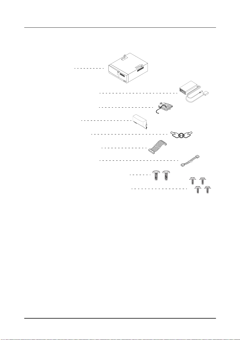
When you unpack the IM-515, make sure you have these items:
Main unit
❏
IM-515
Accessories
❏
Power supply (*)
❏
CPU cooling fan
❏
Back cover
❏
Keys (2 pieces)
❏
FDD ribbon cable
❏
FDD power cable
❏
Screws for an FDD (2 pieces)
❏
Screws for an HDD (4 pieces)
(*) Note that the package does not include a power cord for the power supply.
Please obtain an appropriate power cord before using the IM-515.
If any of these items is damaged or missing, please contact your
dealer for assistance.
After unpacking, save the packing materials so that you can reuse
them for future transport.
Introduction 3
Page 14
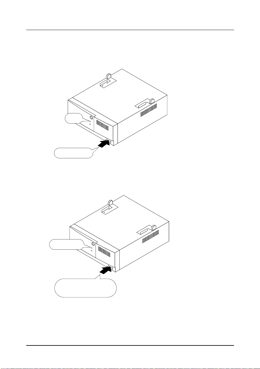
Power On and Off
Power on
Off
Press once
Power off
1. Check if the power LED is off.
2. Press the power switch once.
3. The power LED goes on.
Lit or flashing
Press and hold down
more than 4 seconds (*)
4 Introduction
1. Check if the power LED is lit or flashing.
2. Press and hold down the power
switch more than 4 seconds (*).
3. The power LED goes off.
(*) Depending on the power managem ent settings in BIOS setup,
the IM-515 may remain on if the button has been pressed less
than 4 seconds.
Page 15
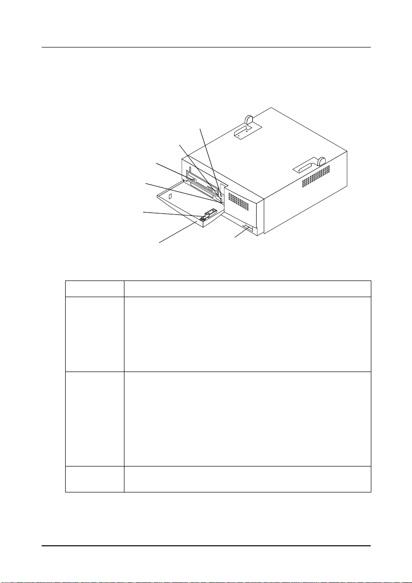
Part Names and Functions
The following illustration is a front view of the IM-515.
Power LED
HDD LED
FDD LED
Reset switch
Key lock
Front cover
Power switch
Part names and functions (front view)
Part name Function
The Power LED indicates power on /o ff and the po wer
management mode.
Power LED
(Green)
Power switch
Reset switch
Lit: Power is on (working mode or doze mode)
Flashing in 2 Hz: standby mode
Flashing in 1 Hz: suspend mode
Off: Power is off (soft off mode)
(See Appendix B for information ab ou t power management.)
Push-type switch to power the IM-515 on or off. This switch also
functions to change the power management mode.
Power on: Push once when IM-515 is off.
Power off: Push and hold down more than 4 seconds (*) when
power is on.
(*) Depending on the setting of th e BIOS se tup, the
IM-515 may not be turned off if it is pressed less
than 4 seconds.
See Appendix B for information about power management.
Push-type switch to reset the IM-515; accessib le usin g a point ed
object like a ball-point pen.
Introduction 5
Page 16

Part names and functions (front view)
Part name Function
Front cover
and key lock
HDD LED
(Green)
FDD LED
The key lock secures the front panel, making the flop py disk
drive inaccessble and securing the cover set.
The HDD LED in dica tes acc essi ng of th e har d di sk dr ive ( when a
hard drive is insta lle d) .
The FDD LED indicates accessing of the floppy disk drive (when
a floppy disk drive is installed). The FDD LED is atta ched to the
floppy disk driv e.
6 Introduction
Page 17
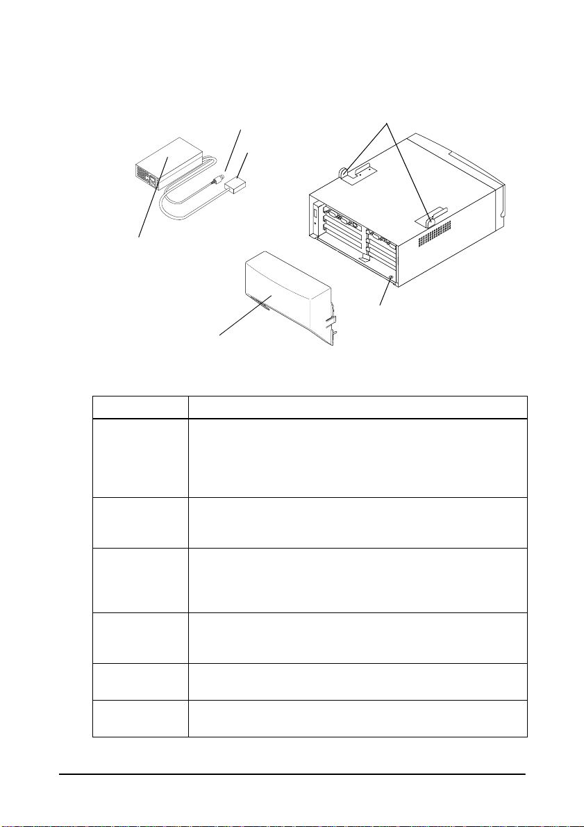
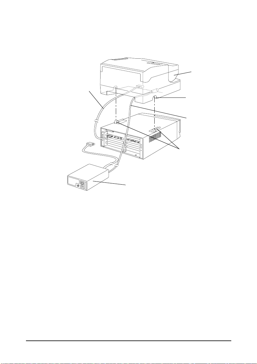
The following illustration is a rear view of the IM-515.
TM printer power cable
IM-515 power cable
Power supply
Back cover
Part names and functions (rear view)
Part name Function
These are guides for the TM printer to position it in the correct
TM printer
position fittings
Back cover
Power supply
TM printer
power cable
(DC)
IM-515 power
cable (DC)
Hole for a lock
chain
location. You can remove the fitting s whe n they are n ot
necessary by removing the securing screw. These fittings are
only for positioning and not for mounting the TM printer. Be
careful not to let the TM pr inter drop when moving the unit.
The back cover hides cables connected to the rear panel.
When attached to the IM-515, it can also cover cables to the
TM printer.
This is an exclusive power supply designed for the IM-515.
Note that this power supply does not have an on/off switch.
Place the power supply where you can easily unplug the
power cord in case of a problem.
This is the power cable for the TM printer.
This is the power cable for the IM-515.
The chassis has a hole for a lock chain
TM printer position fittings
A hole for a lock chain
Introduction 7
Page 18
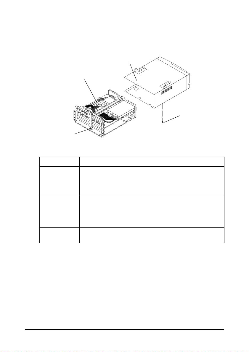
The illustration below is the view when the IM module is removed
from the cover.
Cover
IM module
Transportation
screw
Plate lock
Part names and functions (when the IM module is removed)
Part Function
The IM module is a control unit without the cover. Before you
IM module
Plate lock and
cover
Transporta tion
screw
can install internal components or change DIP switch or
jumper settings, you need to remove the cover from the IM
module.
The plate lock prevents the inside of the unit from falling
when it is moved because of the unit’s sliding structure. This
hook can be opened or cl osed easily, and it also is used as a
knob to remove an internal module. The hook is locked
automatical ly when the internal module is inserted.
The IM module is secured to the cover during shipping by a
transportation screw.
8 Introduction
Page 19
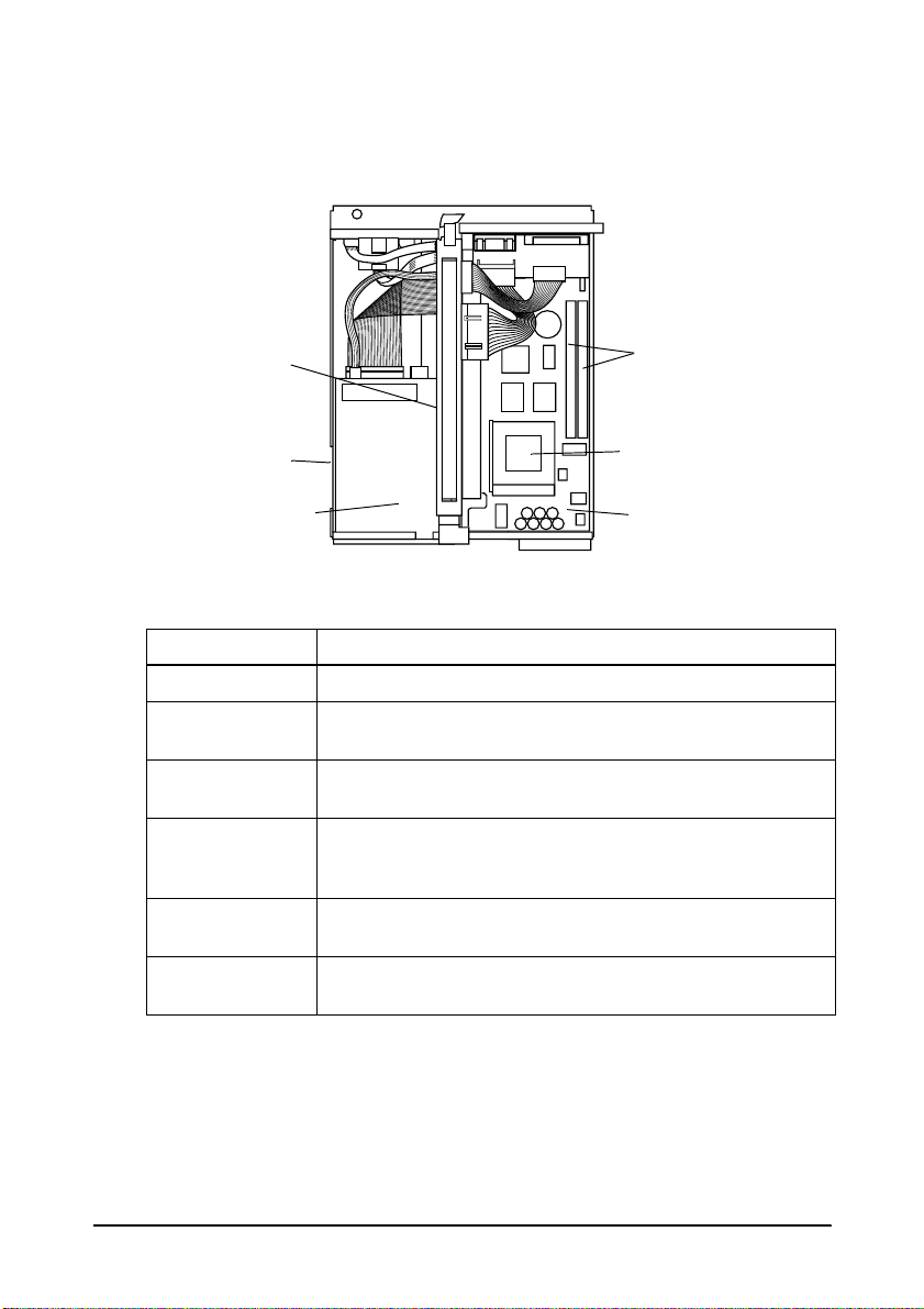
The following illustration shows the major components in the IM
module.
Interconnection
board
Hard disk drive
(under floppy
disk drive)
Floppy disk drive
Part name and functions (major components)
Part name Function
Main board Main board of the IM-515.
CPU socket
(Socket 7)
SIMM sockets
Hard disk drive
Floppy disk drive
Interconnection
board
CPU socket. See Appendix D for the supported CPUs. The
CPU cooling fan shou ld be attached after in stalling a CPU.
Two SIMM sockets are provided. See Appendix D for details
on the SIMMs.
One mount is available for a 2.5-inch hard di sk dri ve
(19 mm or 0.75” maximum) with an IDE/EIDE contro ller
conforming to MCC standards.
One mount is available for a 3.5-inc h floppy disk drive with
720KB/1.44MB storage capacity.
The interconnection board contains the jumpers to set
COM port functions.
SIMM sockets
CPU socket (Socket 7)
Main board
Introduction 9
Page 20
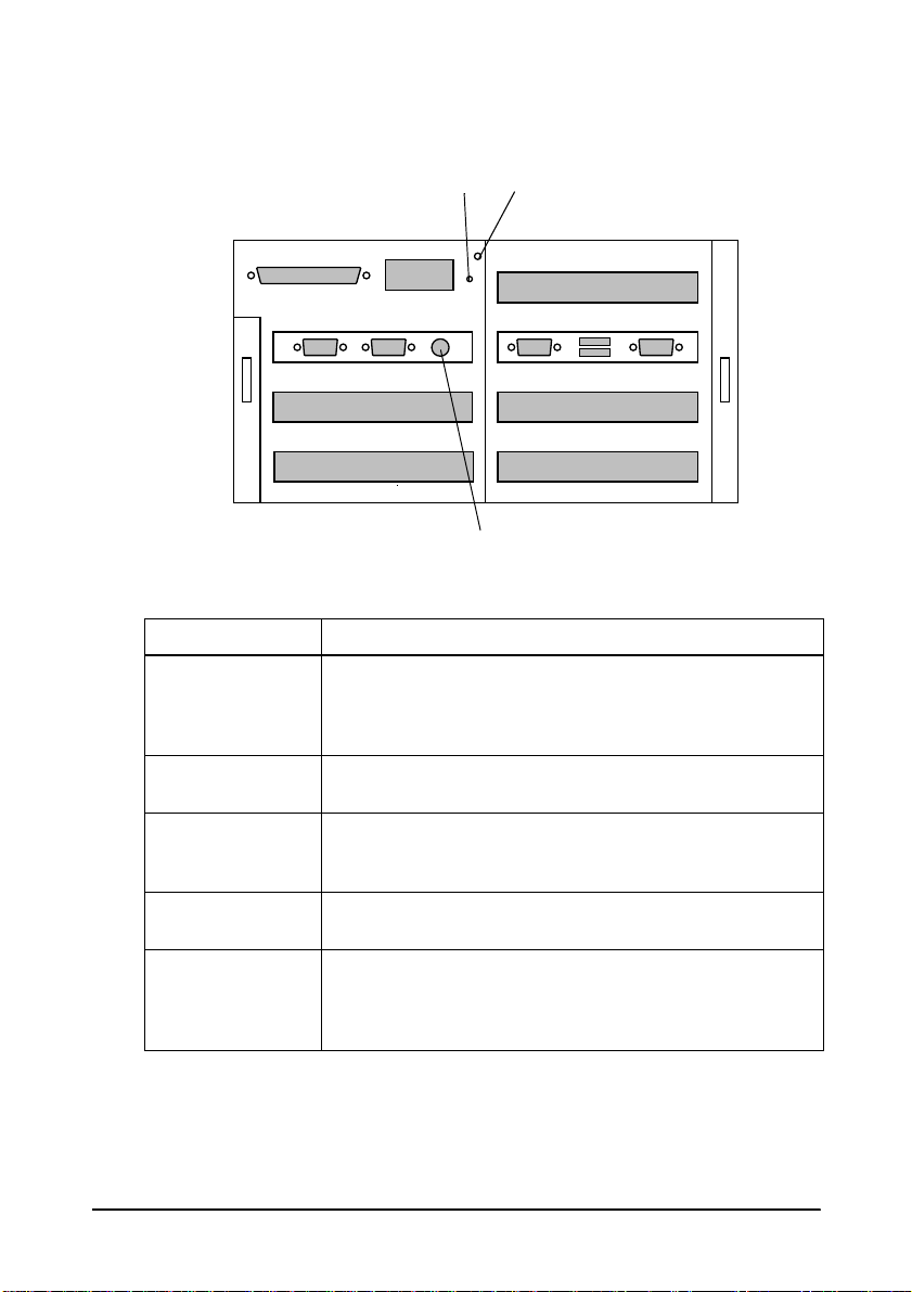
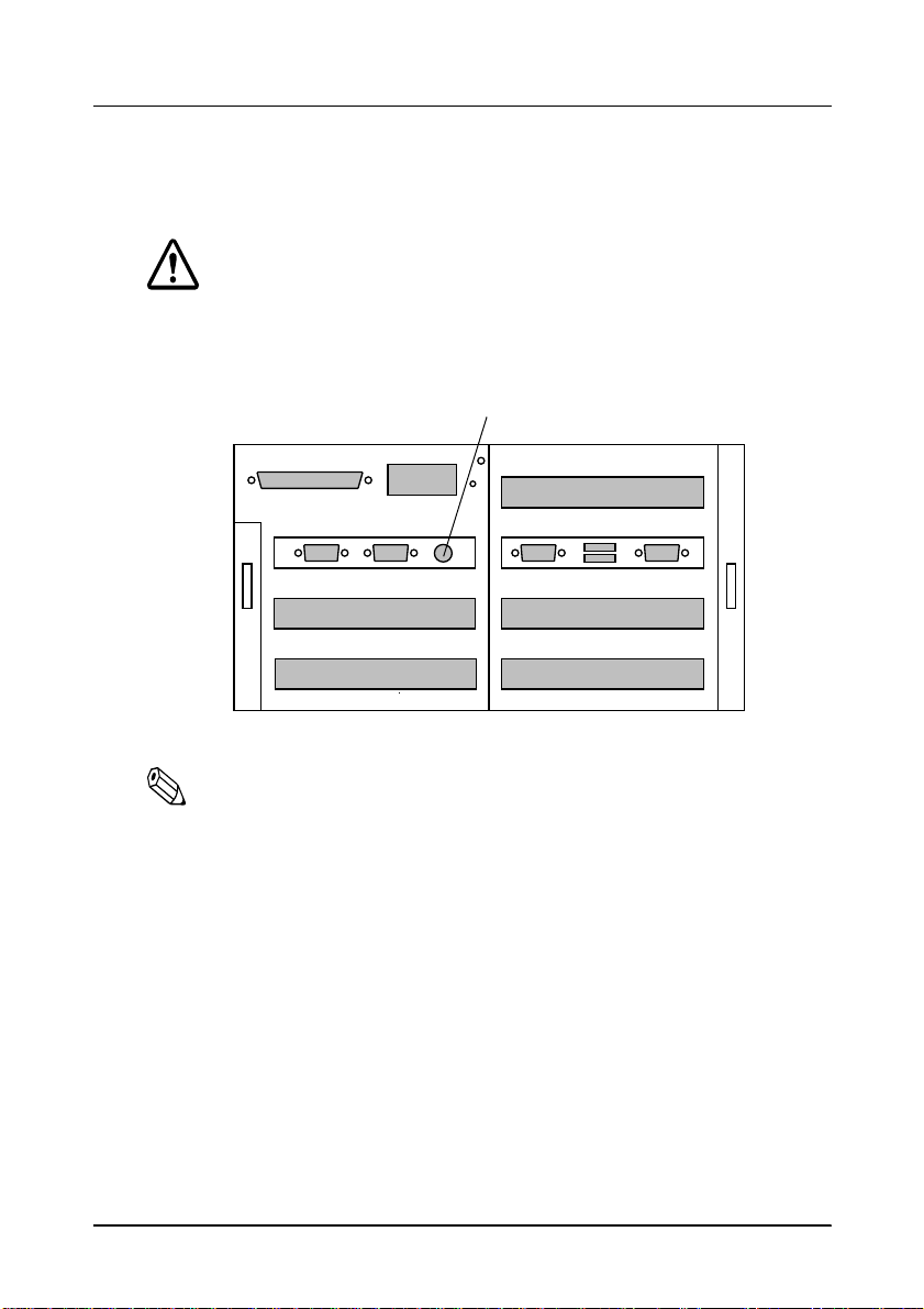
The illustration below is the rear panel of the IM-515.
LPT1
COM1
Frame ground
DC IN
COM2
PCI slot
ISA slot
Transportation screw storage hole
FG
COM3
Keyboard/Mouse
Part name and functions (rear panel)
Part name Function
COM1 to 4, LPT1,
USB1 and 2
keyboard/mouse
connectors
DC IN connector
PCI, ISA, and
exclusive
expansion slots
Frame ground
screw
Transportation
screw storage hole
Interface connectors. Each interface connector has an
icon based on the PC97 standard by Microsoft
Corporation. See Appendix D for details on the interfaces.
DC power IN connector. The power supply DC cable is
connected here.
Expansion slots . See Appendix D for details .
If your interface cable needs a frame ground, use this
screw.
The IM module is secured by the transportation screw on
the bottom of the unit to prevent damage by vibration.
The removed screw can be attached in this hole to
prevent it from becoming lost.
PCI slot
USB1
COM4
USB2
PCI slot
Exclusive slot
10 Introduction
Page 21

Handling Guidelines
Observe these guidelines for proper usage:
❏
Make sure you re ad the safety pre ca utions in this manual
before you use the IM-515.
❏
Make sure the total power requirements of all devices receiv ing
power from the IM-515 does not exceed the IM-515 power
limitations. See Appendix D for details.
❏
When you transport the IM-5 15 i n i ts ship pi ng container, make
sure you replace the transportation screw.
❏
Do not block any slots or openings on the IM-515. These are
provided for the ventilation necessary to ensure reliable
operation and protection from overheating.
❏
TM printer position fittings are only for positioning and not for
mounting the TM printer. Be careful not to let the TM printer
drop when moving the unit.
❏
Never hold the IM-515 by the back cover. This cover cannot
support the weight of the unit, so it may fall onto the floor.
❏
Except when installing the PC card, always use the PC card
cover (*) to protect it from static electricity.
(*) If you have the optional OI-B05, close the front cover of the
IM-515. If you have the optional OI-B06, attach the PCMCIA
slot cover enclosed with the OI-B06 package. See page 2-17 for
details on the PCMCIA slot cover.
❏
When you move the IM-515, make sure the IM module is
secured by the plate lock. The module could fall fr om t he cov er
if it isn’t secured.
❏
Make sure any device connected to the AC outlet of the power
supply does not consume more than 200 VA.
Introduction 11
Page 22

❏
Do not connect to electri cal outl ets that are cl ose to devices that
generate voltage fluctuations or electrical noise. In particular,
stay clear of devices that use large electric motors.
❏
Do not place the side of the power supply connecting the
power cord or DC cables down.
❏
Always connect the DC cables before plugging the power cord
into the wall outlet.
❏
Be sure to push the end of the power cord all the way into the
AC inlet. The fitting on the cord should make contact with the
back of the inlet.
❏
When disconnecting power, always unplug the power cord
from the wall outlet before disconnecting the DC cables.
❏
When disconnecting a DC cable, hold it firmly at the connector
area. Do not tug on the cord itself.
❏
To clean the unit, wipe with a dry or slightly moistened (and
firmly wrung) cloth. Never clean the unit while it is plugged
into the wall outlet.
❏
Never attempt to stretch the cords to make a connection. The
power cord and DC cables must have adequate slack at all
times during use.
❏
Never allow the power supply to hang from the power cord or
DC cables.
12 Introduction
Page 23

Usage and Storage Environment
Keep away from the following:
❏
Direct sunlight
❏
High temperature and humidity
❏
Extreme changes in temperature or humidity
❏
Heating and cooling equipment
❏
Volatile materials
❏
High levels of dust
❏
Locations where it might become wet
❏
Fire
❏
Vibration and impact.
Introduction 13
Page 24

About This Manual
❏ Chapter 1
❏ Chapter 2
jumpers, and installing component devices into the IM-515.
❏ Chapter 3
❏ Appendix A to Appendix E
management functions, loop back connector information,
specifications, and list of the EPSON sales subsidiaries and
their addresses.
contains guidelines on setting up the IM-515.
contains information on setting t he DIP switches and
contains information on using system utilities.
contain error messages, power
14 Introduction
Page 25

Chapter 1
Set Up Guidelines
The IM-515 is designed so it can use various combinations of
components or peripherals. Therefore, the setup procedure
depends on your system configuration. This chapter explains the
essential information for setting up your IM-515 system.
General Setup Procedure
The following table shows you the ge neral procedur e for setting u p
the IM-515. Follow this procedure for whatever you install.
Detailed descriptions for each items follow this section.
General Setup Procedure
Step # Set up items
Step 1 Install internal components
Step 2 Set jumpers and DIP switches
Step 3 Connect the TM printer
Step 4 Connect your peripherals
Step 5 Connect the power supply
Step 6 Attach the back cover
Step 7 Set the system configuration using BIOS setup
Step 8 Set the supervisor password
Step 9 Install your OS (operating system) or application software
Step 10 Charge the battery
Set Up Guidelines 1-1
Page 26

Precautions
If you open the cover of the IM-515, observe these precautions:
Caution
Components on the internal boards in the IM-515 can get
hot. Turn off the IM-515, and wait at least 10 minutes for
components to cool before you remove the cover.
To prevent damage, make sure you turn off the IM-515 and
disconnect the power supply. You must disconnect the
power supply because the electrical current is flowing in
some parts of the circuit even when t he power is turned off.
To prevent damage, make sure you disconnect any
peripheral devices.
To avoid generating static electricity and damaging the
components, ground yourself by touching a grounded met al
surface before you touch any component.
To avoid contamination, do not touch the connectors on the
components.
Step 1 - Installing Internal Components
If you want to install internal components in the IM-515, you need
to remove the transportation screw and the cover first. Check the
table below to see where these procedures are described; then
follow the instructions on that page.
Work See page
Removing the transportation screw 2-1
Removing the IM module from the cover 2-2
1-2 Set Up Guidelines
Page 27

Once you remove the cover from the IM module, turn to the
appropriate sections in Chapter 2 and follow the instructions for
installing the component.
Work See page
Installing a CPU an d a C PU co o lin g fa n 2-3
Installing a SIMM 2-6
Installing a hard disk drive 2-8
Installing a floppy di sk driv e 2-11
Installing a PCI/ISA card 2-14
Installing a PCMC IA expa ns i on mod ule 2-16
When you have the components installed, go to next section.
Step 2 - Jumper/DIP Switch Settings
If you installed a CPU, you need to set the jumpers and DIP
switches. If you want to provide +5 V or +12 V power to COM1 to
COM4, you also need to set the jumpers.
Check the table below to see wher e these p rocedures are described;
then follow the instructions on that page.
Work You need to See page
If you have installed a CPU
If you plan to provide +5 V or
+12 V to COM1 to COM4
Set JP3 and DIP SW1 on th e
main board
Set JP1 on the
interconnection board
2-20
2-28
When you have finished, reattach the IM module to the cover.
Set Up Guidelines 1-3
Page 28

Step 3 - Connecting the TM Printer
The following TM printers can be connected to the IM-515:
❏
EPSON TM-H5000/H5000II series
❏
EPSON TM-U950 series
To set up the TM printer itself, see the operator’s manual for the
TM printer.
Follow these steps to connect the TM printer:
Note:
You need an appropriate interface cable. The interface cable is not
enclosed in your IM-515 package.
1. Set the TM printer on the IM-515 so that the printer hooks fit
into the hol lows in the TM printer.
1-4 Set Up Guidelines
Page 29
2. Connect the interface cable to the TM printer, referring to the
operator’s manual for the TM printer.
TM printer
Interface cable
Power supply
Hollow in
the printer
DC cable for
the TM printer
Printer hooks
3. Connect the other end of the interface cable to the IM-515.
4. Connect the DC cable of the power supply to the TM printer.
Set Up Guidelines 1-5
Page 30
Step 4 - Connecting Your Peripherals
You can connect various peripherals to the IM module using the
connectors on the back panel.
Caution
See Appendix D for power limitations for any device that
draws its power from the IM-515.
Keyboard/Mouse
PCI slot
LPT1
DC IN
FG
USB1
COM1
COM2
PCI slot
ISA slot
COM3
Exclusive slot
USB2
PCI slot
COM4
Note:
For some peripherals, you may need to change the jumper settings.
See page 2-28 for more information.
1-6 Set Up Guidelines
Page 31

Step 5 - Connecting the Power Supply
Follow these steps to connect the power supply:
1. Make sure you read the safety precautions in this manual.
2. Connect the DC cable connector (rectangular connector) for the
power supply to the DC IN connector on the IM-515. Push the
connector in as far as it will go.
DC cable connector
Power supply
3. Connect the power cord to the power supply.
Note:
Note that the package does not include a power cord for the power
supply. Please obtain an appropriate power cord before using the
IM-515.
4. Insert the other end of the power cord into an electrical outlet.
See Appendix D for additional information on the power supply.
Set Up Guidelines 1-7
Page 32

Step 6 - Attaching the Back Cover
Follow the procedures below to attach the back cover:
1. Remove the tape securing the spacers on both sides of the back
cover.
2. Move spacers in the direction indicated by arrow (1).
3. Insert the tab on one side of the cover first; then push the tab on
the other side into place.
4. Move the spacers in the direction indicated by arrow (2).
Back cover
1
2
Tab
Spacer
Caution
Never lift the IM-515 by the back cover. This cover cannot
support the weight of the IM-515, so it could drop.
1-8 Set Up Guidelines
Page 33

Step 7 - Setting the BIOS Setup Utility
The BIOS setup utility defines how the system is configured. The
number of items you need to set depends how you configure the
system. This section explains the essential settings for configuring
the IM-515.
The first time you setup the IM-515 system, you need to run this
program to set the correct date and time. If you installed a floppy
disk drive or SIMM, you may need to use this program. If you do
not use a floppy or hard disk drive, you also need to run this
program.
To start the BIOS setup, turn to page 3-1; then follow the
instructions on that page .
Work See page
Starting the BIOS setup 3-1
Check the table below to see wher e these p rocedures are described;
then follow the instructions on that page.
Work You need to See page
First time s e t up of the
IM-515
Installing a floppy di sk
drive
Not using a floppy disk
drive
Installing a SIMM
If you do not have a h ard
disk drive
Set the date and time using the
STANDARD CMOS SETUP menu
Set the correct type using the
STANDARD CMOS SETUP menu
Set Drive A to “None” in the
STANDARD CMOS SETUP menu,
and set the O nboard FDC
Controller to "Disabled" in the
INTEGRATED PERIPHERALS menu
Change setting, if you want to use
parity SIMMs. Use BIOS FEATURES
SETUP menu
Set HARD DISKS to "None" in the
STANDARD CMOS SETUP menu,
and set the On-chip Primary IDE to
"Disa bled" in the INTEGRA TED
PERIPHERALS menu.
3-5
3-6
3-6
3-15
3-8
3-6
3-14
Set Up Guidelines 1-9
Page 34

Step 8 - Setting the Drawer Password
When a cash drawer is connected to the TM printer , you need to set
the drawer password. If the password is not set, anyone can open
the drawer using the IM-515’s device diagnostics utility.
Turn to page 3-26; then follow the instructions on that page.
Work See page
Defining a drawer password 3-26
Step 9 - Installing your OS or Application software
If you install a n OS (operating system) and application software
onto the IM-515, perform it in this step.
Step 10 - Charging the Batteries
The IM-515 contains a rechargeable Vanadium-Lithium battery
that backs up the real-time clock, CMOS RAM data, and NVRAM
data. The battery is not charged fully at the factory. You need to
charge the battery before you use the IM-515 for the first time. If
you have not used the IM-515 for a long time, you also need to
charge the battery.
The battery is being charged when the IM-515 is being turned on.
Use the following time table for charging.
Item Description
Time for full charge 40 hours or more
Backup time 30 days or more (wit h full ch a r ge )
1-10 Set Up Guidelines
Page 35

Chapter 2
Component Installation
This chapter explains how to install components into the IM-515.
The chapter also describes jumper and DIP switch functions.
Removing the Transportation Screw
The IM module is secured to the cover during shipping by a
transportati on screw. Follow t hese steps to rem ove this screw:
1. Turn the IM-515 over so the bottom of the unit faces up; then
locate the tra nsportation screw.
2. Use a #2 Phillips screwdri ver to turn the screw
counterclockwise and remove it.
Transportation screw
3. Locate the storage hole on the back panel of the IM-515.
Component Installation 2-1
Page 36

4. Screw the transportation screw into the storage hole in the ba ck
panel.
Storage hole
FG
Caution
When you transport th e IM-515 in its shippi ng con taine r, make
sure you replace the transportation screw to the bottom of
the IM-515.
Removing the IM Module from the Cover
Before you can install or remove any components from the IM
module or change jumper/DIP switch settings, you ne ed to remove
the IM module from the cover. Follow these steps:
1. Make sure the transportati on screw ha s been remove d. (See the
previous section.)
2. Open the front panel. If it is locked, use the key provided to
open the lock.
2-2 Component Installation
Page 37

3. Set the tab on the plate lock to
module out, as shown below:
Tab on the plate lock
When you are ready to replace the IM module in the cover, slide it
in until it is all the way in the cover. Close the front panel, and if
necessary, use the key to lock it.
UNLOCK
and pull the IM
Installing a CPU
The IM module contains a 321-pin ZIF (Zero Insertion Force)
Socket 7. The following CPU types can be installed in it:
❏
Intel Pentium P54C (75 MHz to 200 MHz)
❏
Intel MMX Pentium P55C (166 MHz to 233 MHz)
❏
AMD K6-PR166(166MHz) to PR200(200 MHz)
Component Installation 2-3
Page 38

Caution
To avoid generating static electr icity and damaging th e CPU,
ground yourself by touching a grounded metal surface
before you touch the CPU.
Do not touch CPU pins with your fingers.
Make sure you install the enclosed CPU cooling fan onto the
CPU to prevent the CPU from overheating.
Follow these steps to install the CPU:
1. Make sure you have the CPU cooling fan enclosed in the
IM-515 package.
2. Lift the release lever of the Socket 7.
3. Insert the CPU in the Socket 7 in the correct orientation, as
shown in the illustration, using the notched corner of the CPU.
The notch should point toward the end of the lever. The CPU
will fit in only one orientation.
Lever
4. Push down t he release lever and lock it.
5. Remove the piece of paper from the rubber sheet attached to
the bottom surface of the CPU cooli ng fan. The r ubber sheet is a
heat sink and must not be removed.
2-4 Component Installation
Notch
Page 39

6. Hold the CPU cooling fan in the direction shown below.
CPU cooling fan
7. Hook the hole in the fan’s clip into the notch in the Socket 7.
Hole in fan’s clip
8. Place the CPU cooling fan on the CPU surface.
9. Push down the opposite side of fan’s clip and hook it. Make
sure the clip is inserted as shown below; otherwise unclip it
and try again.
Component Installation 2-5
Page 40

10. Connect the fan cable to connector CN7. Arrange the cable so
cable wires do not touch the fins of either the CPU cooling fan
or case fan of the IM-515.
CN7
Note:
You must set jumpers and DIP switches for the CPU you installed.
Installing or Removing a SIMM
The main board supports two 72-pin, 32-bit SIMMs (Single Inline
Memory Modules) of 4, 8, 16, 32, or 64MB for a memory size
between 4MB and 128MB. SIMMs can be either 60ns or 70ns Fast
Page Mode (FPM), or Enhanced Data Out (EDO). The system
allows installation of a single SIMM. However, it is recommended
that you use SIMMs in pairs, both of the same type and capacity.
Caution
To avoid generating static electricity and damaging the
SIMMs, ground yourself by touching a grounded metal
surface before you touch a SIMM.
To avoid contamination, do not touch the connectors on the
SIMM.
2-6 Component Installation
Page 41

Note:
ECC can be supported in the following conditions:
• Use a pair of parity SIMMs.
• Use the BIOS setup and set the Memory Parity/ECC check to
“Enabled” in the BIOS Features Setup menu.
Make sure the SIMMs are the same type and capacity.
Follow these steps to install or remove the SIMMs:
1. Install a SIMM into the inner SIMM socket first. Position the
SIMM at a 45 degree angle over the socket. Make sure t he notch
on the SIMM points toward the CPU, as shown below.
Notch
2. Push the SIMM into the socket until it is seated firmly.
3. Tilt the SIMM until it is upright, guiding the hole at each end of
the SIMM over the retaining post at each end of the SIMM
socket. If it does not go in smoothly, do not force it; pull it all
the way out and try again. Make sure the SIMM is properly
installed and locked by the tabs on both sides of the socket.
Component Installation 2-7
Page 42

4. Install another SIMM using the procedure above.
5. To remove the SIMM, use your fingers or a small screwdriver
to carefully pull away the metal tabs that secure the SIMM at
each end. The SIMM falls to the side. Lift it out of the socket.
Make sure you store the SIMM in an anti-static bag.
Note:
To use parity SIMMs, you need to enable the "Memory Parity/ECC
Check" setting in BIOS setup.
Installing a Hard Disk Drive
You can install a 2.5-inch hard disk drive [19 mm (0.74 inch) high]
in the IM module.
Caution
Handle the hard disk drive gently. Small shocks or vibrati ons
could damage the drive.
To avoid contamination, do not touch drive connectors.
Follow these steps to install the hard disk drive:
1. Make sure you have the four cup head screws enclosed in the
IM-515 package.
2-8 Component Installation
Page 43

2. Remove the screw fastening the hard disk mounting bracket,
and pull it out as shown below.
Screw
Hard disk
mounting
bracket
3. Attach the hard disk drive onto the mounting bracket, by
sliding the hard disk drive as shown below and fixing it with
the four cup head screws enclosed in the IM-515. The
tightening torque for all fo ur screws must not exceed 29. 4 cN·m
(3 kgf·cm).
Component Installation 2-9
Page 44

4. Slide the drive assembly into the chassis so that the notches
along the bottom of the drive assembly are under the chassis
tabs.
Chassis tabs
5. Push the drive assembly in gently until you feel the connector
fit into place.
6. Secure the mounting bracket to the IM module with the screw
you removed in step 2, as shown below.
2-10 Component Installation
Screw
Page 45

Installing a Floppy Disk Drive
You can install a 3.5-inch floppy disk drive in the IM module.
Follow these steps to install the floppy disk drive:
1. Make sure you have the FDD lock plate, FDD ribbon cable,
FDD power cable, and the two binding head screws enclosed in
the IM-515 package.
2. Remove the floppy disk drive slot cover at the front of the IM
module. Remove the screw securing the slot cover to the
chassis; then lift the slot cover out. Store the slot cover and
screw in case you remove the floppy disk drive later.
3. Remove a spacer and a screw attached to the IM module
chassis.
Screw
Spacer
Component Installation 2-11
Page 46

4. Secure the spacer and FDD lock plate to the bottom of the
floppy disk drive with the screw you removed in the step
above. Make sure you attach the FDD lock plate in the correct
direction. The bent part should fit as shown below
s
Screw
Bent part
Spacer
FDD lock plate
Bottom of drive
5. Mount the floppy disk drive assembly onto the IM module
chassis. Then push the drive assembly toward the front face to
meet two screw holes in the floppy disk drive and the IM
module chassis.
Push the drive
CN18
2-12 Component Installation
Screws
CN9
Page 47

6. Secure the floppy disk drive assembly with the two binding
head screws enclosed in the IM-515 package. See the
illustration i n step 5.
7. Connect the FDD cables as described in the steps below:
1. Connect the one end of the FDD ribbon cable to connector
CN9 on the IM-515, and connect the other end to the drive.
Shape the ribbon cable as shown in the illustration in step 5.
2. Connect the one end of the FDD power cable to connector
CN18 on the IM-515, and connect the other end to the drive.
See the illustration in step 5.
Note:
If you installed a 1.44MB, 3.5-inch drive, you do not need to set the
drive type in BIOS setup, because this is the default setting. If you
installed any other type of floppy disk drive or do not use a floppy
disk drive, you must change the setting using the BIOS setup.
To remove the floppy disk drive, reverse the installation
procedure. When you r emove the drive fr om the frame, fol low the
steps below.
1. Insert your hand under the drive in the place shown with the
arrow, and press the insulation sheet upward at the area
shown below.
Press here upward from bottom
* This illustratio n does not have the flo p p y di s k dr iv e
to show you the portion to press.
By doing this, you unlock the FDD lock plate from the frame.
Component Installation 2-13
Page 48

2. Slide the drive toward the arrow shown below to remove it.
Installing a PCI/ISA Card
You can install up to three PCI cards in the PCI expansion slots.
You also can install one ISA card in the ISA expansion slot.
The IM-515 does not have an onboard video function, so you must
install either an ISA vi deo boar d or PCI video boar d befor e you u se
the IM-515.
FG
PCI slot
ISA slot
(*) Note: When the front PCMCIA expan sion mo du le (OI- B05) is used , the
maximum length of the card in this slot is 130 mm (5.1”)
PCI slot
PCI slot
(*)
2-14 Component Installation
Page 49

The maximum size of PCI/ISA cards is as follows:
Max.
size
Length Width
240 mm/130 mm
(9.4/5.1 inches)
107 mm
(4.2 inches)
Height
(Parts side)
12 mm
(0.47 inch)
Height
(Solder side)
10 mm
(0.39 inch)
Caution
When you install PCI/ISA cards, make sure the drawing
current of the cards does not exceed the limits shown on
page D-7.
To avoid contamination, do not touch the card connectors.
Follow these steps to install a PCI/ISA card:
1. Remove the screw securing the slot cover. Then slide the slot
cover out. Keep the screw to secure the ISA/PCI card to the IM
module. Store the slot cover in case you remove the ISA/PCI
card later.
Slot cover
Screw
Component Installation 2-15
Page 50

2. Gently guide the card into the connector; then push the card in
firmly (but carefully) to insert it fully . You should feel the
connector fit into place. If the card does not go in smoothly, do
not force it; pull it all the wa y out and try a gain.
PCI/ISA card
Screw
3. Secure the PCI/ISA card to the IM module with the screw you
removed in step 1 .
Installing a PCMCIA Expansion Module (PC Card Slot)
Caution
When you connect PC cards, make sure the dr awing current
of the cards does not exceed the limits shown on page D-7.
To avoid contamination, do not touch PC card connectors.
2-16 Component Installation
Page 51

Follow these steps to install an expansion module for a PC card.
1. Remove the screw securing the slot cover. Then slide the slot
cover out. Keep the screw to secure the PCMCIA expansion
mod u l e t o t h e IM m o dule. Store the slot cover in case you
remove the PCMCIA expansion module later
Slot cover
Screw
2. Push both sides of the PCMCIA slot cover in, and remove it.
PCMCIA
slot cover
Component Installation 2-17
Page 52

3. Gently guide the module into the connector. Then push the
module in firmly (but carefully) to insert it fully. You should
feel the connector fit into place. If the card does not go in
smoothly, do not force it; pull it all the way out and try again.
Expansion module
for PC card
4. Secure the PC card module to the IM module with the screw
you removed in step 1.
5. Attach the PCMCIA slot cover you removed in step 2. Insert
the tab on one side of the PCMCIA slot cover into the notch in
the expansion module; then push the tab on the other side into
place.
Note:
Remove the PCMCIA slot cover before you install or remove PC
cards.
Caution
Make sure you always attach the slot cover to the PC
card. The slot cover discharges static electricity in your
body. If you do not attach the cover, the IM-515 could
lock up when you insert or remove the PC cards.
2-18 Component Installation
Page 53

Note:
You need to setup the PCMCIA driver on your IM-515 before it can
recognize PC cards in the slots on the PCMCIA expansion
module.See the installation manual for the PC card for details.
Setting Jumpers/DIP Switches
The IM-515 contains two circuit boards with jumpers or DIP
switches you can set. The following sections describe setting the
jumpers and DIP switches on each these boards.
Note:
“Short” in the description below means to connect a pair of pins
with a plastic jumper cap. “Open” means the plastic jumper cap is
connected to only a single pin or no jumper cap is connected.
Settings also are shown graphically below.
Short =
Open =
or
or
or
or
Component Installation 2-19
Page 54

Main Board Jumper/DIP Switch Settings
The main board contains four sets of jumpers and a single set of
DIP switches.
JP1 JP2 JP3
SW1
JP4
JP1: Use this jumper to remove NVRAM fr om the memory
map. To do that, set this jumper to “Open.”
JP2: Use this jumper when the system does not boot
because of an incorrect BIOS setup. This jumper clears
CMOS RAM. No plastic jumper cap is mounted on
this jumper. If you want to use the jumper, remove
any one of the jumper caps set to “Open” on the main
board, and use it for JP2.
Follow the steps below to clear the CMOS RAM.
1. Turn off the IM-515 and remove a jumper cap.
2. Set the JP2 to short.
3. Turn the IM-515 on.
4. Turn off the IM-515 again.
5. Return the jumper cap you removed in step 1.
2-20 Component Installation
Page 55

JP3: This set of jumpers sets the CPU voltage. See the table
titled “CPU voltage settings” below for details.
JP4: This jumper switches the modes of the second cache
on the main board. Always set this jumper to “Ope n”
(pipelined burst) on the IM-51 5. No plast ic jumper cap
is mounted on this jumper.
SW1: This set of switches sets the CPU speed. See the table
titled “CPU spee d settings” below f or details.
Component Installation 2-21
Page 56

Main board jumper/DIP switch settings
Jumper Function Settings
JP1
JP2
JP3 CPU voltage — —
JP4
Enabling NVRAM
for POS
Clearing CMOS
RAM
Secondary cache
mode
Open Disabled
Short (*) Enabled
Open (*) Normal use
Short Clear
Open (*) Pipelined burst
Settings
illustrated
Description
See table
below.
SW1 CPU speed — —
*Factory setting
2-22 Component Installation
Short Liner burst
See table
below.
Page 57

CPU voltage settings
Pins
7 & 8
Open Open Open Open 2.0 V
Open Open Open Short 2.1 V
Open Open Short Open 2.2 V
Open Open Short Short 2.3 V
Pins
5 & 6
Pins
3 & 4
Pins
1 & 2
Settings
illustrated
5
678
5
678
5
678
5
678
CPU
voltage
1
3
4
2
1
3
4
2
1
3
4
2
1
3
4
2
CPU
1
5
3
Open Short Open Open 2.4 V
4
2
678
1
5
3
Open Short Open Short 2.5 V
4
2
678
1
5
3
Open Short Short Open 2.6 V
4
2
678
Component Installation 2-23
Page 58

CPU voltage settings
Pins
7 & 8
Open Short Sh o rt Short 2. 7 V
Short Open Open Open 2.8 V
Short Open Open Short 2.9 V
Short Open Sh ort Open 3.0 V
Pins
5 & 6
Pins
3 & 4
Pins
1 & 2
Settings
illustrated
5
678
5
678
5
678
5
678
CPU
voltage
1
3
4
2
1
3
4
2
1
3
4
2
1
3
4
2
CPU
Intel MMX
Pentium (166 to
233 MHz)
AMD-K6 (PR166
and PR200)
Short Open Short Short 3.1 V
Short Short Open Open 3.2 V
2-24 Component Installation
1
5
3
4
2
678
1
5
3
4
2
678
Page 59

CPU voltage settings
Pins
7 & 8
Short Short Open Short
Short Short Short Ope n 3.4 V
Short Short Short Short 3.5 V
*Factory setting
Note:
Pins
5 & 6
Pins
3 & 4
Pins
1 & 2
Settings
illustrated
5
678
5
678
5
678
CPU
voltage
1
3
3.3 V
(*)
4
2
1
3
4
2
1
3
4
2
CPU
Intel Pentium (75
to 200 MHz)
For a CPU that has a dual power sources, voltages lis te d ab ov e apply to
the CPU core, and its I/O voltage is always at 3.3 V.
Component Installation 2-25
Page 60

CPU speed settings
CPU
Frequency
(MHz)
CPU
rate
CPU
clock
(MHz)
Settings
illustrated
CPU rate
CPU clock
SW
1-1SW1-2SW1-3SW1-4SW1-5SW1-6
Intel
Pentium
Intel
Pentium
Intel
Pentium
Intel
Pentium
Intel
Pentium
Intel
Pentium
75 1.5 x 50 OFF OFF OFF ON ON ON
90 1.5 x 60 OFF OFF OFF ON OFF OFF
(*)
100
1.5 x 66 OFF OFF OFF OFF OFF OFF
120 2.0 x 60 ON OFF OFF ON OFF OFF
133 2.0 x 66 ON OFF OFF OFF OFF OFF
150 2.5 x 60 ON ON OFF ON OFF OFF
O N
1
O N
1
O N
1
O N
1
O N
1
O N
1
6
5
432
6
5
432
6
5
432
6
5
432
6
5
432
6
5
432
Intel
Pentium
Intel
Pentium
166 2.5 x 66 ON ON OFF OFF OFF OFF
200 3.0 x 66 OFF ON OFF OFF OFF OFF
2-26 Component Installation
O N
1
O N
1
6
5
432
6
5
432
Page 61

CPU speed settings
CPU
Frequency
(MHz)
CPU
rate
CPU
clock
(MHz)
Settings
illustrated
SW
1-1SW1-2SW1-3SW1-4SW1-5SW1-6
Intel
MMX
Pentium
166 2.5 x 66 ON ON OFF OFF OFF OFF
Intel
MMX
200 3.0 x 66 OFF ON OFF OFF OFF OFF
Pentium
Intel
MMX
233 3.5 x 66 OFF OFF OFF OFF OFF OFF
Pentium
AMD-K6
(PR166)
AMD-K6
(PR200)
166 2.5 x 66 ON ON OFF OFF OFF OFF
200 3.0 x 66 OFF ON OFF OFF OFF OFF
**Factory setting
O N
1
O N
1
O N
1
O N
1
O N
1
6
5
432
6
5
432
6
5
432
6
5
432
6
5
432
Component Installation 2-27
Page 62

Interconnection board jumper settings
The interconnection board has JP1, which contains four blocks of
jumpers. These jumpers control the function of pin 1 for COM1 to
COM4.
JP1
Use the information in the following table t o change the jumpers on
the interconnection board
Caution
Do not short more than two jumpers in the same jumper block;
otherwise you may damage the IC chips on the IM-515.
Interconnection board jumper settings
Jumper JP1 Function Settings Settings illustrated Description
Pins 1 & 2
1
5
3
79111315
17 19
Short (*)
20 22
18
14 16
79111315
14 16
79111315
17 19
18
17 19
20 22
Block #1
(pins 1
to 6)
Setting
pin 1 of
COM1
Pins 3 & 4
Short
Pins 5 & 6
2
1
2
1
6810 12
4
5
3
6810 12
4
5
3
Short
20 22
18
2
6810 12
4
14 16
2-28 Component Installation
RS-232
23
21
DCD
signal
24
23
21
+5 V
24
23
21
+12 V
24
Page 63

Interconnection board jumper settings
Jumper JP1 Function Settings Settings illustrated Description
RS-232
23
21
14 16
17 19
18
20 22
DCD
signal
24
Pins 7 & 8
Short (*)
1
2
5
3
6810 12
4
79111315
Block #2
(pins 7
to 12)
Block #3
(pins 13 to
18)
Setting
pin 1 of
COM2
Setting
pin 1 of
COM3
Pins 9 & 10
Short
Pins 11 & 12
Short
Pins 13 & 14
Short (*)
Pins 15 & 16
Short
Pins 17 & 18
Short
1
2
1
2
1
2
1
2
1
2
5
3
6810 12
4
5
3
6810 12
4
5
3
6810 12
4
5
3
6810 12
4
5
3
6810 12
4
79111315
14 16
79111315
14 16
79111315
14 16
79111315
14 16
79111315
14 16
17 19
18
17 19
18
17 19
18
17 19
18
17 19
18
20 22
20 22
20 22
20 22
20 22
23
21
+5 V
24
23
21
+12 V
24
RS-232
23
21
DCD
signal
24
23
21
+5 V
24
23
21
+12 V
24
Component Installation 2-29
Page 64

Interconnection board jumper settings
Jumper JP1 Function Settings Settings illustrated Description
RS-232
23
21
14 16
17 19
18
20 22
24
DCD
signal
Pins 19 & 20
Short (*)
1
2
5
3
6810 12
4
79111315
Block #4
(pins 19 to
24)
Setting
pin 1 of
COM4
*Factory settings
Pins 21 & 22
Short
Pins 23 & 24
Short
1
2
1
2
5
3
6810 12
4
5
3
6810 12
4
79111315
14 16
79111315
14 16
17 19
18
17 19
18
20 22
20 22
23
21
+5 V
24
23
21
+12 V
24
2-30 Component Installation
Page 65

Chapter 3
Using the System Utilities
The IM-515 comes with the following utility programs in system
ROM:
❏ BIOS setup, for defining the system configuration.
❏ Device diagnostics, for troubleshoo ting devices attached to the
IM-515.
These programs and the factory default options for this IM-515 are
stored in ROM. New configuration settings are stored in CMOS
RAM, which is backed up by a battery.
Using BIOS Setup
BIOS setup defines how the system is configured. You need to run
this program the first time you configure the IM-515. You need to
run it again if you change the configuration.
Caution
Do not change setting values not described here. Changing
them creates the possibility that the IM-515 may not work. If
this happens, see “In Case of Problems” on page 3-3.
Starting BIOS Setup
Follow these steps to start BIOS setup:
1. Turn on or reset the system.
Using the System Utilities 3-1
Page 66

2. Press the
on, or press
Delete
Delete
key immediately after switching the system
when the following message appears
briefly at the bottom of the screen:
Press DEL to enter SETUP.
3. If a supervisor password is set, a message appears in the center
of the screen:
ENTER PASSWORD
Type the supervisor password, and press
Enter
4. The BIOS setup starts.
Setup Keys
The following table shows how to navigate in set up using the
keyboard.
Key functions
Key Function
Arrow keys Select an item.
Main Menu: Quit and do not save changes to CMOS RAM.
Esc key
PgUp key or
+ key
PgDn key or
– key
F1 key
F2 key or
Shift+F2
F5 key
F6 key Load the BIOS defaults, only for Option Page Setup Menu
F7 key Load the Setup defaults
F10 key Save all the CMOS changes, only for Main Menu
Status Page Setup Menu and Option Page Setup Menu:
Exit current page and return to Main Menu
Increase the numeric value or make changes
Decrease the numeric value or make changes
General help, only for Status Page Setup Menu and Option
Page Setup Menu
Change color from a total of 16 colors. F2 to select color
forward, Shift+F2 to select color backward
Restore the previous CMOS value from CMOS, only for Option
Page Setup Menu
.
3-2 Using the System Utilities
Page 67

Getting Help
Press F1 to pop up a small help window that describes the possible
selections. To exit the Help Window press
Esc
or the F1 key again.
In Case of Problems
If, after making and saving system changes in setup, you discover
that your computer no longer boots, clear the CMOS RAM using
the jumper JP2 on the main board. See page 2-20 for the
instructions to clear the CMOS RAM.
Main Menu
When you enter the BIOS setup utility, a main menu appears on the
screen. Use the arrow keys to highlight items and press
accept and enter the sub-menu. A brief description of each
highlighted selection appears at the bottom of the screen.
The following is a brief summary of the items you can set.
Brief description of main menu
Items you can s et Descriptions
STANDARD CMOS SETUP Options in the original PC AT-compatible BIOS.
BIOS FEATURES SETUP Enhanced BIOS options.
POWER MANAGEMENT
SETUP
LOAD BIOS DEFAULTS
LOAD SETUP DEFAULTS Setup defaults are factory settings for the IM-515.
INTEGRATED PERIPHERALS
SUPERVISOR PASSWORD
Advanced Power Management (APM) options.
BIOS defaults are the settings for the most stable,
minimal-performance system operations. These
settings make the system boot-up stable. However,
system performance may not be optimized.
I/O subsyst em s th at de pend on the integ r a ted
peripherals controller in your system.
Change, set, or disable a password. The supervisor
password permits access to BIOS setup.
Enter
to
Using the System Utilities 3-3
Page 68

Brief description of main menu
Items you can s et Descriptions
USER PASSWORD
SAVE & EXIT SETUP Save settings in the CMOS RAM and exit setup.
EXIT WITHOUT SAVING Abandon all changes and exit setup.
Change, set, or disable a password. The user
password allows power-on access.
3-4 Using the System Utilities
Page 69

Standard CMOS Setup
i
i
i
i
i
i
When you enter Standard CMOS Setup, the following menu
appears on the screen. Do not change the settings for the shaded
items (Note that the actual screen does not have this shading.)
Date (mm:dd:yy) : xxx, xxx xx xxxx
me (hh:mm:ss) : xx : xx : xx
T
HARD DISKS TYPE SIZE CYLS HEAD PRECOMP L ANDZ SECTOR MODE
--------------------------------------------- ------------------------ Pr
mary Master : Auto 0 0 0 0 0 0 Auto
mary Slave : Auto 0 0 0 0 0 0 Auto
Pr
Secondary Master : Auto 0 0 0 0 0 0 Auto
Secondary Slave : Auto 0 0 0 0 0 0 Auto
Drive A : 1.44M, 3.5 in.
Floppy 3 Mode Support : Disabled Extended Memory: XXXXXK
deo : EGA/VGA --------------------------
V
Halt On : All Errors Total Memory: XXXXXK
t : Select Item PU/PD/+/- : Modify
ESC : Qu
F1 : Help (Sh
ft)F2 : Change Color
The following de scribes items you can set on this menu.
Standard CMOS setup
Items you
can set
Date --- Press the right or left arr ow key to move to
Time --- The time format is based on a 24-hour
Options
(*) : SETUP defaults
(**): BIOS defaults
Base Memory: XXXK
Other Memory: XXXK
Descriptions
the desired field (date, month, year).
Press the PgUp or PgDn key to increment
the setting, or type the desired value into
the field.
clock. For example, 1 p.m. is 13:00:00.
Press the right or left key to move to the
desired field. Press the PgUp or PgDn key
to increment the setting, or type the
desired value into the field.
Using the System Utilities 3-5
Page 70

Standard CMOS setup
Items you
can set
HARD DISKS Auto (*)
Drive A None (**)
Halt On All Errors (*),(**)
Options
(*) : SETUP defaults
(**): BIOS defaults
User
None (**)
360KB, 5.25 in.
1.2MB, 5.25 in.
720KB, 3.5 in.
1.44MB, 3.5 in. (*)
2.88MB, 3.5 in.
No Errors
All, But Keyboard
All, But Diskette
All, But Disk/Key
Descriptions
Sets the HDD ty pe.
Auto: The system checks the HD D an d
set the type au t omatically.
User: You can set each parameters.
None: If you do not use the HDD, select
this option.
You can use this to select the correct
specificatio ns for th e f lo ppy di sk driv e
installed in the IM-515. If you do not use a
floppy disk drive, select None.
During the power on self test (POST), the
system stops if BIOS detects a hardware
error. You can tell BIOS to ignore certain
errors during POST and cont in ue t he
boot-up pro cess. Thes e are the
selections:
3-6 Using the System Utilities
All Errors: If BIOS detects any
non-fatal error, POST
stops and prompt s
you to take
corrective action.
No Errors: POST does not stop
for errors.
All, But Keyboard: POST does not stop
for a keyboard error,
but stops for all other
errors.
All, But Diskette: POST does not stop
for floppy disk drive
errors, but stops for all
other errors.
All, But Disk/Key: POST does not stop
for a keyboard or disk
error, but stops for all
other errors.
Page 71

BIOS Features Setup
i
i
i
i
i
i
i
i
i
i
When you enter BIOS Features Setup, the following menu appears
on the screen. Do not change the settings for the shaded items
(Note that the actual screen does not have this shading.)
Virus Warning : Disabled Video BIOS Shadow : Enabled
CPU Internal Cache : Enabled C8000-CBFFF Shadow : D
External Cache : Enabled CC000-CFFFF Shadow : D
Qu
ck Power On Self Test : Enabled D0000-D3FFF Shadow : Disabled
Boot Sequence : A,C,SCSI D4000-D7FFF Shadow : D
Boot Up Floppy Seek : Disabled D8000-DBFFF Shadow : Disabled
Boot Up NumLock Status : On DC000-DFFFF Shadow : Disabled
Boot Up System Speed : High
Gate A20 Option : Fast
Memory Parity/ECC Check : Disabled
Typematic Rate Setting : Disabled
Typematic Rate (Chars/Sec) : 6
Typemat
c Delay (Msec) : 250
Secur
ty Option : Setup
PS/2 mouse funct
PCI/VGA Palette Snoop : D
OS Select For DRAM > 64MB : Non-OS2 F1 : Help PU/PD/+/- : Mod
Report No FDD For WIN 95 : No F5 : Old Value (Sh
on control : Enabled
sabled ESC : Quit : Select Item
F6 : Load BIOS Defaults
F7 : Load Setup Default
sabled
sabled
sabled
ft)F2 : Color
fy
Using the System Utilities 3-7
Page 72

The following describes the items you can set on this menu.
BIOS Features Setup
Items you
can set
Virus Warning Enabled
Quick Power
On Self Test
Boot
Sequence
Boot Up
Floppy Seek
Boot Up
NumLock
Status
Memory
Parity/ECC
Check
Typematic
Rate Setting
Typematic
rate (Char/
Sec)
Options
(*): SETUP defaults
(**): BIOS defaults
Disabled (*), (**)
Disabled (**)
Enabled (*)
A, C, SCSI (*), (**)
C, A, SCSI
D, A, SCSI
E, A, SCSI
F, A, SCSI
SCSI, A, C
SCSI, C, A
C only
Disabled (*)
Enabled (**)
Off (**)
On (*)
Disabled (*), (**)
Enabled
Disabled (*), (**)
Enabled
6 (*), (**)
8
10
12
15
20
24
30
Descriptions
When this setting is Enable d, you receive
a warning message if a program
(specifically, a virus) attempts to write to
the boot sector or the partition table of
the hard disk drive. Keep in mind that this
feature protects only the boot sector, not
the entire hard drive.
Select Enabled to activate the quick
POST.
The original IBM PCs loaded the
operating system from dr iv e A (a flo ppy
disk), so IBM PC-compatible systems are
designed to search for an operating
system first on drive A, and then on drive
C (hard disk). However, the BIOS now
offers a large number of boot devices
and boot sequen ce options.
When this setting is Enabled, the floppy
disk drive seeks during boot up.
Toggles between On or Off to control the
state of the Num Lock key when the
system boots.
To use parity for the SIMMs, select
Enabled.
When this setting is Disabled, the
following two item s (Typematic Rate and
Typematic Delay) are irrelevant.
Keystrokes repeat at a rate determined
by the keyboard controller in your system.
When the typematic rate setting is
enabled, you can select a typematic
rate (the rate at which character repeats
when you hold down a key) of 6, 8, 10,12,
15, 20, 24 or 30 characters per second.
3-8 Using the System Utilities
Page 73

BIOS Features Setup
Items you
can set
Typematic
Delay (Msec)
Security
Option
PS/2 mouse
function
control
OS Select For
DRAM >
64MB
C8000-CBFFF
Shadow
CC000-CFFFF
Shadow
D0000-D3FFF
Shadow
D4000-D7FFF
Shadow
D8000-DBFFF
Shadow
DC000-DFFFF
Shadow
Options
(*): SETUP defaults
(**): BIOS defaults
250 (*), (**)
500
750
1000
Setup (*), (**)
System
Disabled
Enabled (*), (**)
Non-OS2 (*), (**)
OS2
Disabled (*), (**)
Enabled
(Same as above) (Sam e as abo v e)
(Same as above) (Sam e as abo v e)
(Same as above) (Sam e as abo v e)
(Same as above) (Sam e as abo v e)
(Same as above) (Sam e as abo v e)
Descriptions
When the typematic rate setting is
enabled, you can select a typematic
delay (the delay bef ore key s trokes begin
to repeat) of 250, 500, 750 or 1000
milliseconds.
You can set passwords in one of two
ways below :
Setup: You must enter a supervisor
password to enter BIOS setup.
System: You need to enter a user
password each time the system
boots. You also must enter a
supervisor password to enter BIOS
setup.
If you use a PS/2 mous e, se lect Enabled.
IRQ12 will be used for the PS/2 mouse.
Disabled will reserve IRQ12 for expansion
cards and the PS/2 mouse will not
function.
You should select OS2 only if you are
running the OS/2 operating system with
greater than 64MB of RAM on your
system.
Selects whether to permit shadowing in
this section of memory .
Using the System Utilities 3-9
Page 74

Power Management
i
i
When you enter Power Management Setup, the following menu
appears on the screen. Do not change the settings the shaded items.
(Note that the actual screen does not have this shading.)
Global PM Timers : Disabled ** Thermal Monitor **
PM Control by APM : Yes CPU Warning Temperature : 60C/140F
MODEM Use IRQ : 3 Current CPU Temperature : xxxC/xxxF
Suspend Option : Static Suspend Current System Temp. : xxxC/xxxF
Beep On Suspend : Disabled ** Fan Speed Monitor **
Video Off Option : Suspend -> Off Current CPU FAN Speed : xxxx RPM
Video Off Methed : DPMS Support Current CASE FAN Speed : xxxx RPM
HDD Power Down : 15 Min VCORE Voltage : xx.xx V
Doze mode : D
Standby Mode : Disabled +5V Voltage : x.xx V
Suspend Mode : Disabled +12V Voltage : xx.xx V
Primary HDD : Disabled -5V Voltage : -x.xx V
Floppy : Disabled
Serial Ports : Enabled ESC : Quit : Select Item
Keyboard : Enabled F1 : Help PU/PD/+/- : Mod
Parallel Ports : Disabled F5 : Old Value (Shift)F2 : Color
Power Button : Green Mode F7 : Load Setup Default
** PM Timers ** ** Voltage Monitor **
sabled +3.3V Voltage : x.xx V
** Timer Reload & Wakeup Events ** -12V Voltage : -xx.xx V
fy
** External Switch ** F6 : Load BIOS Defaults
3-10 Using the System Utilities
Page 75

The following describes the items you can set on this menu.
Power Management
Items you
can set
Global PM
Timers
PM Control
by APM
Modem Use
IRQ
Beep On
Suspend
Options
(*): SETUP defaults
(**): BIOS defaults
User Define
Disabled (*), (**)
Min Saving
Max Saving
No
Yes (*), (**)
NA (**)
3 (*)
4
5
7
9
10
11
Disabled (*), (**)
Once
1 Min Interval
Descriptions
Selects power management functions
using the timers for doze, standby, and
suspend.
User Define: You can set the time for
each timer.
Disabled: When you select
Disabled, power
management featur es for
doze, standb y, and
suspend are disabled.
Min Saving: The system sets the timers
as following.
Doze timer: 10 min
Standby timer: 30 min
Suspend timer: 1 hou r
Max Saving: The system sets the timers
as following.
Doze timer: 1 min
Standby timer: 2 min
Suspend timer: 3 min
This item allows you to set power
management without using APM
(Advanced Power Management).
Set the interrupt that the modem uses.
When the interrupt chosen in this item
occurs, the system returns to working
mode from suspend mode. If you do not
use this feature, select NA.
This option controls the beep for suspend
mode. See Appendix B for detail.
Using the System Utilities 3-11
Page 76

Power Management
Items you
can set
Video Off
Option
Video Off
Method
HDD Power
Down
Doze Mode Disabled (*), (**)
Options
(*): SETUP defaults
(**): BIOS defaults
Always ON
Suspend -> O ff (*)
Susp, Stby ->Off (**)
All Modes ->Off
Blank Screen
V/H SYNC+Blank
DPMS Support
(*), (**)
Disabled (**)
1 min
-15 min (*)
1 min
-10 min
20 min
30 min
40 min
50 min
1 hour
Descriptions
This option determines when to activate
the video off feature.
Always ON: The video off feature is
disabled.
Suspend -> Off: When the system enters
suspend mode, the
video off feature goes
active.
Susp, Stby -> Off: When the system enters
suspend or standby
mode, the video off
feature goes active.
All Modes -> Off: The video off feature
goes active in all
power management
modes.
Set this field for your video card and
monitor.
This field allows you to set the period of
inactivity before the hard disk drive
enters standby mode (motor power is
off). You can select Disabled to keep the
hard disk drive running continually.
This field sets the peri od of in act iv it y
before the CPU enters doze mode.
3-12 Using the System Utilities
Page 77

Power Management
Items you
can set
Standby
Mode
Suspend
Mode
Primary HDD Disabled (*), (**)
Floppy Disabled (*), (**)
Serial Ports Disabled (**)
Keyboard Disabled(**)
Parallel Ports Disabled(*),(**)
Power Button Disabled(**)
Options
(*): SETUP defaults
(**): BIOS defaults
Disabled (*), (**)
1 min
-10 min
20 min
30 min
40 min
50 min
1 hour
Disabled (*), (**)
1 min
-10 min
20 min
30 min
40 min
50 min
1 hour
Enabled
Enabled
Enabled (*)
Enabled(*)
Enabled
Green Mode(*)
Power OFF
Descriptions
This field sets the peri od of in act iv it y
before the system goes into standby
mode from doze mod e.
This field sets the peri od of in act iv it y
before the system goes into suspend
mode from stand by mode.
If you select Enabled, the system returns
to working mode from the power saving
modes (doze, standby, or suspend
modes) when this devi ce is accessed.
(Same as above.)
(Same as above.)
(Same as above.)
(Same as above.)
Set the power switch functions. See
Appendix B for details.
Using the System Utilities 3-13
Page 78

Integrated Peripherals
i
i
i
i
When you enter the Integrated Peripherals menu, the following
appears on the screen. Do not change the settings for the items in
dark shading. The items with light shading may not appear on the
screen, depending on the settings of other items. (The actual screen
does not have this shading.)
On-Chip Primary IDE : Enabled Onboard Parallel Port : 378/IRQ7
On-Chip Secondary IDE : Disabled Parallel Port Mode : SPP
IDE Primary Master PIO : Auto ECP Mode Use DMA : 3
IDE Primary Slave PIO : Auto
IDE Secondary Master PIO : Auto
IDE Secondary Slave PIO : Auto
IDE Primary Master UDMA : Auto
IDE Primary Slave UDMA : Auto
IDE Secondary Master UDMA : Auto
IDE Secondary Slave UDMA : Auto
IDE HDD Block Mode : Enabled
On-Chip USB Controller : Disabled
USB Keyboard Support : Disabled
Onboard FDC Controller : Enabled
Onboard Ser
Onboard Ser
Onboard Ser
Onboard Ser
al Poer 1 : 3F8/IRQ4 F1 : Help PU/PD/+/- : Modify
al Poer 2 : 2F8/IRQ3 F5 : Old Value (Shift)F2 : Color
al Poer 3 : 3E8/IRQ11 F6 : Load BIOS Defaults
al Poer 4 : 2E8/IRQ10 F7 : Load Setup Default
The following describes the items you can set on this menu.
Integrated Peripherals
Items you
can set
On-Chip
Primary IDE
On-Chip
Secondary
IDE
IDE Primary/
Secondary
Master/Slave
PIO
Options
(*): SETUP defaults
(**): BIOS defaults
Disabled
Enabled (*),(** )
Disabled (*), (**)
Enabled
Auto (*),(** )
Mode 0
Mode 1
Mode 2
Mode 3
Mode 4
ESC : Quit : Select Item
Descriptions
Select Enabled to activate the IDE
interface.
Select Enabled to activate the
secondary IDE channel.
The four IDE PIO (Programme d Inp ut /
Output) fields let yo u se t a PIO mode (0-
4) for each of t he four IDE d ev ices that
the onboard IDE interfac e sup ports.
Modes 0 through 4 provid e successively
increased performance. In Auto mode,
the system automatically de termines the
best mode for eac h device.
3-14 Using the System Utilities
Page 79

Integrated Peripherals
Items you
can set
IDE Primary/
Secondary
Master/Slave
UDMA
On-Chip USB
Controller
USB
Keyboard
Support
Onboard
FDC
Controller
Onboard
Serial Port 1/2
Onboard
Serial Port 3/4
Options
(*): SETUP defaults
(**): BIOS defaults
Disabled (**)
Auto(*)
Mode 0
Mode 1
Mode 2
Disabled(*),(**)
Enabled
Disabled(*),(**)
Enabled
Disabled
Enabled (*),(** )
Disabled
3F8, IRQ4
2F8, IRQ3
3E8, IRQ11
2E8, IRQ10
338, IRQ11
238,IRQ10
Disabled
3F8, IRQ4
2F8, IRQ3
3E8, IRQ4
2E8, IRQ3
3E8, IRQ11
2E8,IRQ10
Descriptions
If your hard drive and your syste m
software both support Ultra DMA, select
Auto to enable BIOS suppo rt.
Select Enabled to activate the USB
controller.
Select Enabled when you use a USB
keyboard.
Select Enabled to use the onboard
floppy disk con t roller (FDC) on the main
board. If you install an add-in FDC or the
system has no floppy drive, select
Disabled in this fiel d.
Select an address and corresponding
interrupt for the serial ports. Here are the
SETUP/BIOS default settings for each port:
Port 1: 3F8, IRQ4
Port 2: 2F8, IRQ3
Select an address and corresponding
interrupt for the serial ports. Here are the
SETUP/BIOS default settings for each port.
Port 3: 3E8, IRQ11
Port 4: 2E8, IRQ10
Using the System Utilities 3-15
Page 80

Integrated Peripherals
Items you
can set
Onboard
Parallel Port
Parallel Port
Mode
ECP Mode
Use DMA
Options
(*): SETUP defaults
(**): BIOS defaults
Disabled
3BC, IRQ7
378, IRQ7 (*),(**)
278, IRQ5
PS/2
EPP1.9
ECP
ECPEPP1.9
SPP (*),(**)
EPP1.7
ECPEPP1.7
0
1
3 (*),(**)
Descriptions
Select an address and corresponding
interrupt for the parallel port.
Select an operating mode for the parallel
port.
SPP: Standard Parallel Port (data flows
from PC to peripheral only)
PS/2: Bidirectional
When the parallel port is set to ECP
mode, this field determines a DMA
channel for the port.
Supervisor/User Password Setting
Follow these steps to set the supervisor or user password.
1. Select Supervisor Password or User Password item on the main
menu screen, and press
Enter
.
To abort the process at any time, press
To clear the password, simply press
a password. Then the password function is disabled.
2. A message appears at the center of the screen:
ENTER PASSWORD :
Type a password up to eight characters and press
Typing a password clears any previously entered password
from CMOS memory.
3-16 Using the System Utilities
Esc
.
Enter
when asked to enter
Enter
.
Page 81

3. Now the message changes:
CONFIRM PASSWO RD :
Again, type the password and press
Enter
.
4. In the security option item in the BIOS features setup screen,
select Setup or System.
Setup
System
You need to enter a supervisor password whenever you
enter the BIOS Setup.
You need to enter a user password each time the system
boots. You also need to enter a supervisor password
whenever you enter the BIOS Setup.
Using Device Diagnostics
The device diagnostics utili ty included in IM -515 syst em ROM lets
you isolate communication problems that the IM-515 or connected
devices may be having. You can use these diagnostics to test the
following:
❏
TM printer operation test
❏
DM display indication test
❏
Cash drawer operation test
❏
Serial port loop-back test
❏
LPT1 port loo p-back test
❏
Printing test of printer connected to LPT1.
Using the System Utilities 3-17
Page 82

Device Diagnostics Utility Conditions
The device diagnostics utility runs under the following conditions.
Device Diagnostics Utility Conditions
Items Conditions
❏
Set the receive buff er to the ma ximum.
❏
Set the selection switch for customer display
connection/non-connection to non-connection (if it has
a selection switch).
❏
Setting of the TM
printer DIP switches
Setting of DIP
switch of the DM
displays
Setup the communication settings to follow the
instruction, if the TM printer does not have the ID function
(ESC/POS
Baud Rate: 9600 bps
Word Length: 8 bits
Parity: None
See the TM printer manual for the setup procedure.
When the TM printer connects to COM1:
❏
Setup the communication setting to follow the
instruction, for a TM printer with ID function (ESC/POS
command).
Baud Rate: Same setting as the TM printer
Word Length: Same setting as the TM printer
Parity: Same setting as th e T M printer
❏
Setup the communication setting to follow the
instruction, when the TM printer does not have the ID
function (ESC/POS
Baud Rate: 9600 bps
Word Length: 8 bits
Parity: None
When the TM printer connects to another port besides
COM1:
❏
Setup the DM display communication setting to follow
the instruction.
Baud Rate: 9600 bps
Word Length: 8 bits
Parity: None
See the DM display manual for the setup procedures
command).
GS I
command).
GS I
GS I
Starting Device Diagnostics
When you start the IM-515, you see the following prompt.
Press F10-Key to start device diagnostics.
3-18 Using the System Utilities
Page 83

When you see the prompt, press
F10
. You see the following dialog
box when you start the device diagnostics utility.
Select TM Port
COM1
COM2
COM3
COM4
LPT1
None
Select the port connected to the TM printer, using the
down arrow
printer, select
key; then press
None
.
Enter
. If you have not co nnected a TM
up arrow
or
You see the device diagnostics screen.
Device diagnostics uses a series of menu bars, pull-down menus,
and dialog boxes that allow you to select options or perform
diagnostic tests. Follow these guidelines for using device
diagnostics:
❏
To display a pull-down menu, use the
arrow
key to highlight the option; then press
left arrow
Enter
or
right
(if
necessary).You can also see the pull-down menu if you press
the key that corresponds to the initial letter of the option. (The
Initialize
❏
To select an option from the pull-down menus, use the
arrow
or
Enter
. If the option has a dialog box, you see it when you press
Enter
.
❏
Press
Esc
option does not have a pull-down menu.)
down arrow
key to highlight the option; then press
to close a pull-down menu or a dialog box.
up
❏
Press the
backspace
key to correct typing.
Using the System Utilities 3-19
Page 84

Device Diagnostics Screen
The device diagnostics screen is divided into the following areas:
❏
TM/drawer
❏
DM
❏
COM ports
❏
LPT1
❏
Messages.
3-20 Using the System Utilities
Page 85

TM/Drawer
The TM/drawer area of the device diagnostics screen displays the
communication se ttings, cash drawer driving pulse signal width,
and the status for the TM printer and cash drawer.
TM/DM information
Setting Description
TM Model
TM Port
TM Reset Signal
Baud Rate Indicates the baud rate that the TM printer is using.
Word Length Indicates the word length that the TM printer is using.
Parity Indicates whether the TM printer is using parity.
Drawer On Time
TM Status
Drawer Status Displays the status (HIGH/LOW) of the cash drawer.
Displays the model name, depending on the type of TM
printer attached to the IM-515.
Displays the TM printer connect ion support that was
selected when you s ta r te d th e device diagnostic s ut ili ty .
Indicates the signal name the system will use to reset the TM
printer. This feature fuctions if the TM printer ha s been set to
allow reset using the RTS or DTR signals.
Displays the pulse width of the signal for opening the cash
drawer.
Indicates the status of the TM printer. See the table below
called “TM status messages” for a description of these
messages.
Using the System Utilities 3-21
Page 86

TM status messages
Message
Disabled —
No
communication
Hardware
error
Priority
(*)
—
1
Description
The port connected to the TM printer is disabled. Set
to Enabled using the BIOS Setup.
❏
Displays this message when a TM printer that does
not have an ID function (ESC/POS
command) is connected. Check whether the DIP
switches of the TM printer are set to the following:
Baud Rate: 9600 bps
Word Length: 8 bits
Parity: None
Although the screen indicates “No
communication,” the device diagnostics utility
can communicate with the TM pr in te r if the DIP
switches are set up correctly. If something is
wrong, check the TM status messages.
❏
The device diagn os t ics ut ili ty ca n no t
communicate with a connected TM printer that
has the ID function (ESC/POS
Check the following items:
❏
The interface cable and power cable are
connected properly to the TM printer.
❏
Make sure you turn off the IM-515 before you
connect the cable.
❏
The TM printer power sw it c h is on .
❏
The TM printer selected when device
diagnostics started is connected to the port.
❏
The TM printer is not performing a self-test
when the device diagnostics utility starts.
❏
The paper FEED button is not pressed when
the device diagnostics utility st art s.
❏
The TM printer is on-line.
If the TM printer does not meet these condition s ,
correct the problem and select the Init ial ize optio n
from the menu bar.
If the printer meets all the above conditions , one of
the following may have occurred:
❏
The print head has overheated.
❏
The TM printer is not working.
The print head is overheated, or the print er is not
working.
GS I
GS I
command).
3-22 Using the System Utilities
Page 87

TM status messages
Message
Paper
feeding
Receipt end 3 The receipt paper path contains no paper.
Journal end 4 T he jou rna l paper path contains no paper.
Paper near-
end
Receipt
near-end
Journal near-
end
Cover open 8 The printer cover is open.
On-line 9 The printer is on-line. The TM print test is possible.
(*) If device diagnostic s de tects more than one TM stat us, it displays the highes t
priority message. (Priority co de 1 is higher than priority code 3.)
Priority
(*)
2 The TM printer is fe ed in g pape r.
5
6
7
Description
The paper roll diameter is too small, or it is not
installed.
The receipt paper roll diameter is too small, or it is not
installed.
The journal paper roll diameter is too small, or it is not
installed.
DM
The DM area on the screen indicates the communication settings
and the status of the DM display.
DM Information
Setting Description
DM port
Baud Rate Indicates the baud rate that the DM display uses.
Word Length Indicates the word length that the DM display uses.
Parity Indicates whether the DM display uses parity.
DM status
Indicates the po rt th a t th e device diagnostics ut ili ty
uses to transmit data.
Indicates DM status. See the table “DM status
messages” below, which explains of these messages.
Using the System Utilities 3-23
Page 88

DM status messages
Message Description
Disabled
No communication
Busy
Ready
The port connected to the DM display is disabled. Set to
Enabled using BIOS setup.
Device diagno s ti cs is not able to commun ic a te wi th th e
DM display. Check the TM printer and DM display for the
following:
❏
The DM display is properly connected. Make sure you
turn off the IM-515 before you connect the cable.
❏
The data communications DIP switch is the same for
the DM display and the TM printer. Make sure you
turn off the IM-515 before you change the settings.
❏
The DM display power sw it ch is on .
❏
The DM display is not executing a self test.
If the DM display does not meet these conditions, correct
the problem and se lec t th e Initialize option from the
menu bar.
If the TM printer and DM display meet the abov e
conditions, on e of th e foll owing may have occ ur red:
❏
The DM display interface circuit on the IM-515 is not
working.
❏
The DM display is not working.
If the DM display’s condition is busy, it is possibly caused
by the following:
❏
The DM display is running a self test.
❏
After the device diagnostics utility starts, the DM
display power was turned off.
The DM display is ready to receive data. A test of the DM
display is possible.
COM port information
The COM ports area of the screen lists the DTR, DSR, RTS, CTS,
DCD, and RI status for each of the available COM ports. When the
port is disabled, you see a message to that effect.
LPT1 information
The LPT1 area of the screen lists the BSY, ACK, PE, SLCT, and ERR
status for the LPT1 port. When the port is disabled, you see a
message to that effect.
3-24 Using the System Utilities
Page 89

Messages
The message portion of the screen displays the result of tests.
Message area
Test category Message Description
TM printer Disabled The port is disabled.
Done
DM display test Disabled The port is disabled.
Done
Drawer kick-out
test
Loop-back test Erro r
LPT1 print test Time out
Disabled The port is disabled.
Done
Disabled The port is disabled.
Ok The test completed successfully.
Disabled The port is disabled.
Ok The print data was sent successfully.
The TM printer test is completed. Check the
printing motion and auto cutter motion.
DM display test is completed. Check
indication.
The drawer kick-out test is compl eted. Check
the motion of the cash drawer.
The diagnostics test failed. This message also
appears when a loop-back connector is not
connected, or the wrong loop-back
connector is connected.
The printer connected to the LPT1 port did not
enter a ready state after 2 seconds.
Using the Setup Menu
The setup menu allows you to create a password for accessing the
drawer kick-out test and to set the length of time for the voltage
signal supplied to the cash drawer solenoid to open it.
Using the System Utilities 3-25
Page 90

Defining a drawer password
Caution
You need to set a drawer password if you connect your
drawer to the TM printer. If the password is not set, anyone
can open the drawer using the drawer kick-out test.
Follow these steps to define a password:
1. Select the Drawer Password option from the setup pulldown menu. You see the following message in a dialog box:
Enter
2. Type the password you want, and press Enter. Passwords can
be 4 to 8 alphanumeric characters. Make sure you enter at least
four characters or numbers. You then see this message:
Re-Enter
3. Type the same password a second time, and press Enter.
The password is now defined. You see the following prompt each
time you select the Drawer kick-out test from the devicetests pull-down menu.
Enter
Type the password and press Ente r to perform the d rawer k ick-out
test.
3-26 Using the System Utilities
Page 91

Changing or deleting a drawer password
Follow these steps to change or delete a password.
1. Select the
down menu. You see this message:
2. Type your current password and press
following message:
3. If you no longer want a p assword, press
now deleted. If you want to define a new password, type the
new password and press
4. Type the same password a second time and press
Drawer Passwo rd
Old
New
Re-Enter
option from the setup pull-
Enter
. You then see the
Enter
. The password is
Enter
. You see this message:
Enter
Setting the Drawe r O N time
Drawer ON time
The
the voltage signal to pass through the solenoid to open the cash
drawer.
To set the time, select the
pull-down menu. You see a dialog box allowing you to enter the
ON time your cash drawer requires. You can enter a value up to
500 (ms). For the appropriate value, see your cash drawer manual.
option sets the length of time required for
Drawer ON time
option from the setup
.
Running Device Tests
The device-tests option on the menu bar allows you to run the
following tests:
❏
TM print test
❏
DM display test
Using the System Utilities 3-27
Page 92

❏ Drawer kick-out test
❏ COM1 loop-back test
❏ COM2 loop-back test
❏ COM3 loop-back test
❏ COM4 loop-back test
❏ LPT1 loop-back test
❏ LPT1 print test.
Note:
Before you perform the loop-back tests, you need to connect an
appropriate loop-back connector to the port. See Appendix C for the
loop-back connector configurations.
TM print test
The following tests are executed during the TM print test:
❏ Receipt print test, which prints a standard print pattern
❏ Auto cutter test (for a printer equipped with an auto cutter
only)
Note:
Before you run the test, make sure the TM status message says online. If it doesn’t, see “TM Status Message.”
When the test is complete, make sure the standard print pattern
printed. For a printer with an auto cutter, make sure th e auto cutter
cuts the receipt.
3-28 Using the System Utilities
Page 93

DM display test
The DM display test sends the following message to the DM
display:
Display Module Test
***** Device Diagnostics *****
Note:
Before you run the DM display test, make sure the DM status
message says Ready. If it doesn't, see the table on page 3-24.
Check the DM display screen to see if the test has been performed.
Drawer kick-out test
The drawer kick-out test opens the cash drawer. If the cash drawer
opens, the test was successful. The TM printer has two drawer
kick-out drive signals: signal 1 (pin 2) and signal 2 (pin 5).
However, this test checks only drawer kick-out drive signal 1.
If you set a password, you see the following prompt when you
select Drawer kick-out test from the menu bar:
Enter
Type your password and press Enter. Device diagnostics tries to
open the cash drawer.
Note:
Before you run the drawer kick-out test, make sure the TM status
message says on-line. If it doesn't, see the table on page 3-22.
COM ports and LPT1 loop-back tests
The following loop-back tests are available:
❏ The COM port test checks the DTR, DSR, CTS, RTS, TXD, and
RXD signals.
Using the System Utilities 3-29
Page 94

❏ The LPT1 port test checks the STROBE
AUTO FEED
SELECT signals.
Note:
Before you run these tests, make sure the port you want to test is
enabled and the appropriate loop-back connector is attached to the
port.
When the tests complete successfully, you see OK in the message
area of the screen. If the test failed, you see an error message.
, PAPER EMPTY, ERR, INIT, SELECT IN, and
, ACK, DATA0, BUSY,
LPT1 print test
The LPT1 print test prints a standard print pattern on th e printer
connected to LPT1. If the printer is busy, you see the time-out
message in the message area of the screen.
Note:
Before you run the LPT1 print test, make sure the LPT1 port is
enabled. Also make sure an appropriate printer is connected to the
LPT1 port.
Initializing Device Diagnostics
When you select Initialize from the menu bar, device
diagnostics restarts the program. If device diagnostics displays No
communication for the TM status of TM/drawer area or DM
status of DM area, fix the problem. Then select this option to reset
the program. See the tables on page 3-22 and 3-24 for more
information.
Leaving Device Diagnostics
When you select Exit from the menu bar, the system reboots.
3-30 Using the System Utilities
Page 95

Appendix A
Error Messages
Error Messages From Hardware Monitor
The IM-515 monitors the power supply voltages, the fan rotation,
and the temperature of the CPU and inside the case. If an irregular
value is detected, the system BIOS displays:
Hardware Monitor found an error, enter POWER
MANAGEMENT SETUP for details
If this happens, press the
Delete
key to enter the BIOS setup; then
find the cause of the problem. The detected items are shown in the
table below.
Hardware monitors
Items Normal range
CPU core voltage Operating voltage ± 0.15 V
+3.3 V 3.3 ± 0.15 V
+5 V 5.0 ±10%
+12 V 12.0 ±10%
–12 V –12.0 ±10%
– 5 V –5.0 –10%
Rotation speed of the
CPU cooling f an
Rotation speed of the
case fan
CPU temperature 70° C (158° F) or less
Temperature inside the
case
70% of normal speed or more
70% of normal speed or more
60°C (140° F) or less
Error Messages A-1
Page 96

POST Messages
During the power-on self test (POST), BIOS either sounds a beep
code or displays a message when it detects a correctable error.
The following is a list of POST messages. An error message may be
followed by a prompt to press F1 to continue or press
BIOS setup.
POST messages
Messages Descriptions
A video error has occurred, and BIOS cannot
Beep
BIOS ROM checksum
error — System halted
CMOS battery failed CMOS battery is no longer functional.
CMOS checksum error —
Defaults loaded
CPU at
nnnn
Press ESC to skip memory
test
Floppy disk(s) fail
HARD DISK initializing
Please wait a moment...
HARD DISK INSTALL
FAILURE
initialize the video screen to display any additional
information. This beep code consists of a single
long beep followed by two short beeps.
The checksum of the BIOS code in the BIOS chip is
incorrect, indicating the BIOS code may have
become corrupt.
Checksum of CMOS is incorrect, so the system
loads the defaul t equipment configuration. A
checksum error may indicate that CMOS has
become corrupt. This error may have been
caused by a weak battery.
Displays the running speed of the CPU.
The user may press
Cannot find or initialize the floppy drive controller
or the drive. If no floppy drives are installed, be sure
the Drive A selection in BIOS se tu p is set to Non e
and the Onboard FDC Controller (under
Integrated Peripherals) is set to Disabled.
Some hard drives require extra time to initi ali ze.
Cannot find or initia lize the hard drive controller or
the drive. If no hard di s k dri ve is ins ta lled, be sure
the HARD DISKS (under Standard CMOS Setup ) is
set to None and the On-Chip Prima ry IDE (under
Integrated Peripherals) is set to Disabled.
to skip the full memory test.
Esc
DEL
to enter
A-2 Error Messages
Page 97

POST messages
Messages Descriptions
Hard disk(s) diagnosis fail
Keyboard error or no
keyboard present
Keyboard is locked out —
Unlock the key
Memory Test:
Memory test fail
Override enabled —
Defaults loaded
Primary master hard disk
fail
Primary slav e ha rd di s k f ai l
Secondary master hard
disk fail
Secondary slave hard
disk fail
The system may run specific disk diagnostic
routines. This message appears if one or more hard
disks return an error when the diagnostics run.
Cannot initialize the keyboard. Make sure the
keyboard is attached correctly and no keys are
pressed during POST. To purposely con fig u re the
system without a keyboard, set the
in BIOS setu p to
ignores the missing keyboard durin g POST .
This message usually indicates that one or more
keys have been pr essed d uring the keyb oard tests.
Be sure no objects are resting on the keyboard.
This message displays during a full memory test,
counting down the memory areas being tested.
If POST detects an error during memory testing,
additional information appears gi ving specifics
about the type and location of the memory error.
If the system cannot boot using the current CMOS
configuration, BIOS can override the current
configuration with a set of BIOS defaults designed
for the mos t stable, minimal- performance system
operations.
POST detects an error in the primary master IDE
hard drive.
POST detects an error in the primary slave IDE hard
drive.
POST detects an error in the secondary master IDE
hard drive.
POST detects an error in the secondary slave IDE
hard drive.
All, But Keyboard
Halt On
. BIOS then
option
Error Messages A-3
Page 98

A-4 Error Messages
Page 99

Appendix B
Power Management
The IM-515 can enter power saving mode if the system detects
inactivity. This power management fea ture is contro lled by
Advanced Power Management (APM) Ver. 1.2 and its support
circuitry. The conditions for entering power saving mode depend
on the settings of the APM or the settings of power management
setup in BIOS setup.
IM-515 Operating Modes
The IM-515 has the following modes of operation:
IM-515 operation modes
Mode Power saving method Power LED
Normal opera ting mode. I n th is mo de,
Working mode
Doze mode
the system offers the fastest
processing speed; however, power
consumption is maximized.
1) The system puts the cache into low
power mode.
2) The system controls the video using
the Video Off Option in the Power
Management Setup menu of BIOS
setup, as listed below.
Suspend -> Off: No control
Susp, Stby -> Off: No control
All Modes -> Off: Turns video off
Always On : No control
On
On
Power Manageme nt B-1
Page 100

IM-515 operation modes
Mode Power saving method Power LED
1) The system puts the CPU into idle
mode.
2) The system puts the cache into low
power mode.
3) The system controls the video using
Standby mode
Suspend mode
Soft Off mode
the Video Off Option in the Power
Management Setup menu of BIOS
setup, as listed below.
Suspend -> Off: N o co ntrol
Susp, Stby -> Off:Turns video off
All Modes -> Off:Turns video off
Always On: No control
1) The system stops CPU clock.
2) The system stops unnecessary clock
generators.
3) The system stops the HDD motor.
4) The system stops CPU and case
fans.
5) The system controls the video using
the Video Off Option in the Power
Management Setup menu of BIOS
setup, as listed below.
Suspend -> Off: Tu rns vid eo off
Susp, Stby -> Off: Turns video off
All Modes -> Off: Turns video off
Always On: No control
The power from the power supply
stops.
Flashes twice a
second.
Flashes once a
second.
Off
There are there kinds of flowcharts to show how the power
management modes changes, as shown below.
❏
Green mode
❏
Disabled mode
❏
Power Off mode
You can change the mode using the Power Button item in the
Power Management Setup menu of BIOS setup.
B-2 Power Management
 Loading...