

Page 1

IM-505
User’s Manual
Using this online user’s guide
The words on the left side of this screen are bookmarks for all the
topics in this guide.
Use the scroll bar next to the bookmarks to find any topic you
want. Click a bookmark to instantly jump to its topic. (If you wish,
you can increase the size of the bookmark area by dragging the
dividing bar to the right.)
Use the scroll bar on the right side of this screen to move through
the text.
Use the zoom tools to magnify or reduce the page display.
Click the Find button if you want to search for a particular term.
(However, using the bookmarks is usually quicker.)
Complete online documentation for Acrobat Reader is located in the Help directory for Acrobat Reader.
Return to main menu
Page 2
Update
Please make the following updates to the IM-505 Operation Manual.
We regret any inconvenience.
Page Updates
2-5 Main Menu - Boot Sequence
to “Boot sequence” on the main menu cannot be
2-6
2-7 Advanced Menu - Integrated Peripherals
to Add the following row at the end of the table:
2-9
selected on the IM-505. Please skip this item.
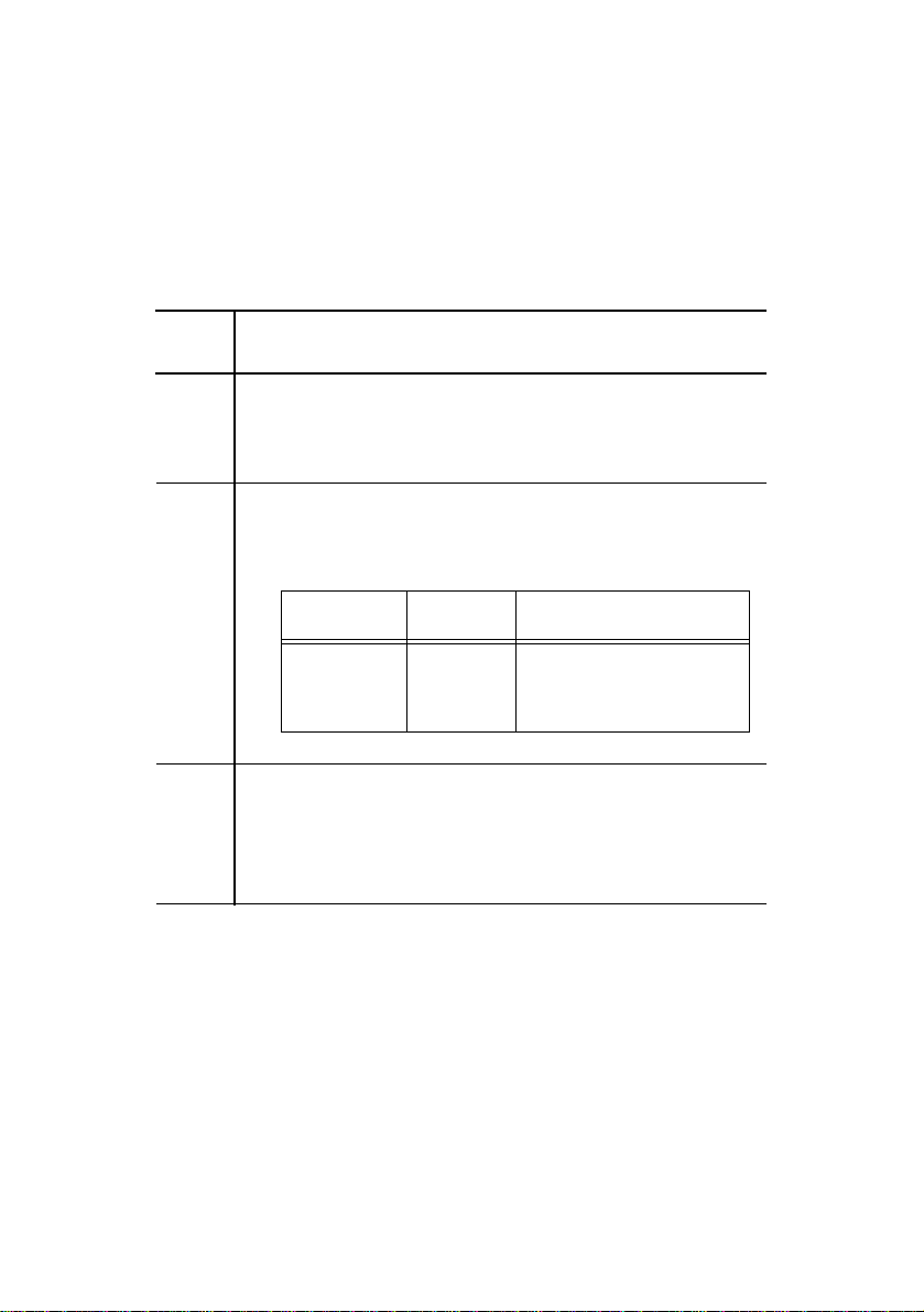
Feature Options Description
Keyboard
Connection
Check
2-12 Using Device Diagnostics
to The IM-505 does not support the diagnostics
2-23
functions. Please skip these pages.
Enabled
Disabled
Checks the keyboard
connecti on during bootup.
400693000
Page 3
IM-505
User’s Manual
400686700
Page 4

Copyright Information
All rights reserved. No part of this publication may be reproduced, stored in a retrieval
system, or transmitted in any form or by any means, electronic, mechanical, photocopying,
recording, or otherwise, without the prior written p ermission of Seiko Epson Corpor ation. No
patent liability is assumed with respect to the use of the information contained herein. While
every precaution has been taken in the prepar ation of this book, Seiko Epson Corporation
assumes no responsibility for errors or omissions. Neither is any liability assumed for
damages resulting from the use of the information contained herein.
Neither Seiko Epson Corporation nor its affiliates shall be liable to the purchaser of this
product or third parties for damage s, losses, costs, or expenses incurred by the purchasers or
third parties as a result of accident, misuse, or abuse of this product or unauthorized
modifications, repairs, or alterations to this produc t, or (exc ludin g the U.S.) fa ilure to strictly
comply with Seiko Epson Corporation’s operating and maintenance instructions.
Seiko Epson Corporation shall not be liable against any damages or problems arising from the
use of any options or any consumable products other than those designated as Original
EPSON Products or EPSON Approved Products by Seiko Epson Corporation.
EPSON is a regist ered trademark of Seiko Epson Corporation.
ESC/POS is a registered trademark of Seiko Epson Corporation.
Intel and Pentium are registered trademarks of Intel Corporation.
6x86 is a trademark of Cyrix Corporation.
AMD K5 is a trademark of Advanced Micro Devices, Inc.
Phoenix is a registered trademark of Phoenix Technologies Ltd.
IBM, PC/AT, and PS/2 are registered trademarks of International Business Machines
Corporation.
Microsoft and Windows are registered trademarks of Microsoft Corporation.
General Notice: Other product and company names used herein are for identification
purposes only and may be trademarks of their respective companies.
NOTICE:
The contents of this manual are subject to change without not ice.
Copyright 1996 © by Seiko Epson Corporation, Nagano, Japan.
Chapter 2: Copyright © 1996, Phoeni x Technologies Ltd. All rights reserved.
Except for use in review, no one may reproduce any part of this chapter in any manner
whatsoever without the written permission of Phoenix Technologies Ltd.
ii
Page 5
FCC CLASS A
FCC COMPLIANCE STATEMENT FOR AMERICAN USERS
This equipment has been tested and found to comply with the limits for a Class A digital
device, pursuant to Part 15 of the FCC Rules. These limits are designed to provide reasonable
protection against harmful int erference when the equipment is operated in a commercial
environment.
This equipment generates, uses, and can radiate radio frequency energy and, if not installed
and used in accordance with the in struction manual, may cause harmful interference to radio
communications. Operation of this equipment in a residential area is likely to cause harmful
interference, in which case the user will be required to correct the interference at his own
expense.
WARNING
The connection of a non-shielded interfa ce cabl e to this produ c t will invalid at e the FCC
Verification of this device and may cause interference levels wh ich exceed the limits
established by the FCC for this eq uipment.
You are cautioned that changes or modifications not expressly approved by the party
responsible for compliance could void your authority to operate the equipment.
FOR CANADIAN USERS
This Class A digital apparatus meets all requirements of the Canadian Interference-Causing
Equipment Regulations.
Cet appareil numérique de la classe A respecte toutes les exigences du Règlement sur le
matériel brouilleur du Canada.
iii
Page 6

Contents
Introduction
Handling Guidelines . . . . . . . . . . . . . . . . . . . . . . . . . . . . . . . . . . . . . . . . . . . . . . . . . . . . . 4
Options . . . . . . . . . . . . . . . . . . . . . . . . . . . . . . . . . . . . . . . . . . . . . . . . . . . . . . . . . . . . . . . 5
List ofTerms . . . . . . . . . . . . . . . . . . . . . . . . . . . . . . . . . . . . . . . . . . . . . . . . . . . . . . . . . . . 5
Warnings, Cautions, and Notes . . . . . . . . . . . . . . . . . . . . . . . . . . . . . . . . . . . . . . . . . . . . . 6
AC Adapter Safety Precautions . . . . . . . . . . . . . . . . . . . . . . . . . . . . . . . . . . . . . . . . . . . . . 7
Supported Devices. . . . . . . . . . . . . . . . . . . . . . . . . . . . . . . . . . . . . . . . . . . . . . . . . . . 9
Usage and Storage Locations. . . . . . . . . . . . . . . . . . . . . . . . . . . . . . . . . . . . . . . . . . . 9
Connecting the AC Adapter to the Power Cord. . . . . . . . . . . . . . . . . . . . . . . . . . . . . 10
Important Safety Rules. . . . . . . . . . . . . . . . . . . . . . . . . . . . . . . . . . . . . . . . . . . . . . . . 10
Additional Safety Precations for AC Adapter . . . . . . . . . . . . . . . . . . . . . . . . . . . . . . 11
How to Use This Manual. . . . . . . . . . . . . . . . . . . . . . . . . . . . . . . . . . . . . . . . . . . . . . . . . . 12
Chapter 1
How to Use This Chapter . . . . . . . . . . . . . . . . . . . . . . . . . . . . . . . . . . . . . . . . . . . . . . . . . 1-1
Unpacking the IM-505 . . . . . . . . . . . . . . . . . . . . . . . . . . . . . . . . . . . . . . . . . . . . . . . . . . . 1-3
Setting Up the IM Module . . . . . . . . . . . . . . . . . . . . . . . . . . . . . . . . . . . . . . . . . . . . . . . . 1-4
Setting Up the IM-505 System . . . . . . . . . . . . . . . . . . . . . . . . . . . . . . . . . . . . . . . . . . . . . 1-27
Charging the Batteries . . . . . . . . . . . . . . . . . . . . . . . . . . . . . . . . . . . . . . . . . . . . . . . . . . . . 1-34
Chapter 2
Using the BIOS Setup . . . . . . . . . . . . . . . . . . . . . . . . . . . . . . . . . . . . . . . . . . . . . . . . . . . . 2-1
Installation
Removing the Transportation Screw . . . . . . . . . . . . . . . . . . . . . . . . . . . . . . . . . . . . . 1-4
Removing the IM Module From the Cover Set . . . . . . . . . . . . . . . . . . . . . . . . . . . . 1-5
Locating Components . . . . . . . . . . . . . . . . . . . . . . . . . . . . . . . . . . . . . . . . . . . . . . . . 1-11
Setting the Jumpers . . . . . . . . . . . . . . . . . . . . . . . . . . . . . . . . . . . . . . . . . . . . . . . . . . 1-12
Installing a CPU. . . . . . . . . . . . . . . . . . . . . . . . . . . . . . . . . . . . . . . . . . . . . . . . . . . . . 1-14
Installing a CPU Cooling Fan . . . . . . . . . . . . . . . . . . . . . . . . . . . . . . . . . . . . . . . . . . 1-15
Installing or Removing a SIMM . . . . . . . . . . . . . . . . . . . . . . . . . . . . . . . . . . . . . . . . 1-16
Installing a Hard Disk Drive . . . . . . . . . . . . . . . . . . . . . . . . . . . . . . . . . . . . . . . . . . . 1-18
Installing a Floppy Disk Drive . . . . . . . . . . . . . . . . . . . . . . . . . . . . . . . . . . . . . . . . . 1-20
Installing an ISA/PCI Card . . . . . . . . . . . . . . . . . . . . . . . . . . . . . . . . . . . . . . . . . . . . 1-21
Installing a PCMCIA Expansion Module (Option) . . . . . . . . . . . . . . . . . . . . . . . . . 1-24
Connecting the TM printer . . . . . . . . . . . . . . . . . . . . . . . . . . . . . . . . . . . . . . . . . . . . 1-28
Connecting Peripherals . . . . . . . . . . . . . . . . . . . . . . . . . . . . . . . . . . . . . . . . . . . . . . . 1-30
Connecting the AC Adapter . . . . . . . . . . . . . . . . . . . . . . . . . . . . . . . . . . . . . . . . . . . 1-31
Attaching the Back Cover . . . . . . . . . . . . . . . . . . . . . . . . . . . . . . . . . . . . . . . . . . . . . 1-33
Lithium Battery . . . . . . . . . . . . . . . . . . . . . . . . . . . . . . . . . . . . . . . . . . . . . . . . . . . . . 1-34
Using System Utilities
Starting the BIOS Setup . . . . . . . . . . . . . . . . . . . . . . . . . . . . . . . . . . . . . . . . . . . . . . 2-2
v
Page 7

Menu Bar . . . . . . . . . . . . . . . . . . . . . . . . . . . . . . . . . . . . . . . . . . . . . . . . . . . . . . . . . . 2-3
Legned Bar . . . . . . . . . . . . . . . . . . . . . . . . . . . . . . . . . . . . . . . . . . . . . . . . . . . . . . . . 2-3
Field Help Window . . . . . . . . . . . . . . . . . . . . . . . . . . . . . . . . . . . . . . . . . . . . . . . . . . 2-4
General Help Window . . . . . . . . . . . . . . . . . . . . . . . . . . . . . . . . . . . . . . . . . . . . . . . . 2-4
Main Menu Selection . . . . . . . . . . . . . . . . . . . . . . . . . . . . . . . . . . . . . . . . . . . . . . . . 2-4
Advanced Menu Selection . . . . . . . . . . . . . . . . . . . . . . . . . . . . . . . . . . . . . . . . . . . . 2-5
Security Menu Selection . . . . . . . . . . . . . . . . . . . . . . . . . . . . . . . . . . . . . . . . . . . . . . 2-5
Power Menu Selection . . . . . . . . . . . . . . . . . . . . . . . . . . . . . . . . . . . . . . . . . . . . . . . 2-6
Using Device Diagnostics . . . . . . . . . . . . . . . . . . . . . . . . . . . . . . . . . . . . . . . . . . . . . . . . . 2-16
Device Diagnostics Utility Conditions. . . . . . . . . . . . . . . . . . . . . . . . . . . . . . . . . . . . 2-17
Starting Device Diagnostics . . . . . . . . . . . . . . . . . . . . . . . . . . . . . . . . . . . . . . . . . . . 2-19
Device Diagnostics Screen . . . . . . . . . . . . . . . . . . . . . . . . . . . . . . . . . . . . . . . . . . . . 2-20
TM/Drawer . . . . . . . . . . . . . . . . . . . . . . . . . . . . . . . . . . . . . . . . . . . . . . . . . . . . . . . . 2-20
DM . . . . . . . . . . . . . . . . . . . . . . . . . . . . . . . . . . . . . . . . . . . . . . . . . . . . . . . . . . . . . . 2-22
Using the Setup Menu . . . . . . . . . . . . . . . . . . . . . . . . . . . . . . . . . . . . . . . . . . . . . . . . 2-25
Running Device Tests . . . . . . . . . . . . . . . . . . . . . . . . . . . . . . . . . . . . . . . . . . . . . . . . 2-26
Initializing Device Diagnostics . . . . . . . . . . . . . . . . . . . . . . . . . . . . . . . . . . . . . . . . . 2-29
Leaving Device Diagnostics . . . . . . . . . . . . . . . . . . . . . . . . . . . . . . . . . . . . . . . . . . . 2-29
Chapter 3
Messages . . . . . . . . . . . . . . . . . . . . . . . . . . . . . . . . . . . . . . . . . . . . . . . . . . . . . . . . . . . . . . 3-1
The IM Module Will Not Start . . . . . . . . . . . . . . . . . . . . . . . . . . . . . . . . . . . . . . . . . . . . . 3-5
The IM Module Always Stops at Bootup . . . . . . . . . . . . . . . . . . . . . . . . . . . . . . . . . . . . . 3-6
The IM Module Does Not Respond . . . . . . . . . . . . . . . . . . . . . . . . . . . . . . . . . . . . . . . . . 3-7
The IM Module Shuts Down . . . . . . . . . . . . . . . . . . . . . . . . . . . . . . . . . . . . . . . . . . . . . . . 3-7
Keyboard Problems . . . . . . . . . . . . . . . . . . . . . . . . . . . . . . . . . . . . . . . . . . . . . . . . . . . . . . 3-7
Monitor Problems . . . . . . . . . . . . . . . . . . . . . . . . . . . . . . . . . . . . . . . . . . . . . . . . . . . . . . . 3-8
The EPSON DM-D Display Problems . . . . . . . . . . . . . . . . . . . . . . . . . . . . . . . . . . . . . . . 3-8
Floppy Disk Problems . . . . . . . . . . . . . . . . . . . . . . . . . . . . . . . . . . . . . . . . . . . . . . . . . . . . 3-9
Floppy Disk Drive Problems . . . . . . . . . . . . . . . . . . . . . . . . . . . . . . . . . . . . . . . . . . . . . . . 3-9
Hard Disk Drive Problems . . . . . . . . . . . . . . . . . . . . . . . . . . . . . . . . . . . . . . . . . . . . . . . . 3-10
TM Printer Problems . . . . . . . . . . . . . . . . . . . . . . . . . . . . . . . . . . . . . . . . . . . . . . . . . . . . . 3-10
Serial Port Problems . . . . . . . . . . . . . . . . . . . . . . . . . . . . . . . . . . . . . . . . . . . . . . . . . . . . . 3-11
Parallel or OCIA Port Problems . . . . . . . . . . . . . . . . . . . . . . . . . . . . . . . . . . . . . . . . . . . . 3-11
Cash Drawer Problems . . . . . . . . . . . . . . . . . . . . . . . . . . . . . . . . . . . . . . . . . . . . . . . . . . . 3-12
PC Card Problems . . . . . . . . . . . . . . . . . . . . . . . . . . . . . . . . . . . . . . . . . . . . . . . . . . . . . . . 3-12
Port 80h Diagnostic Codes . . . . . . . . . . . . . . . . . . . . . . . . . . . . . . . . . . . . . . . . . . . . . . . . 3-12
Appendix A
CPU and Memory . . . . . . . . . . . . . . . . . . . . . . . . . . . . . . . . . . . . . . . . . . . . . . . . . . . . . . . A-1
Controllers . . . . . . . . . . . . . . . . . . . . . . . . . . . . . . . . . . . . . . . . . . . . . . . . . . . . . . . . . . . . . A-2
Interfaces . . . . . . . . . . . . . . . . . . . . . . . . . . . . . . . . . . . . . . . . . . . . . . . . . . . . . . . . . . . . . . A-2
Security . . . . . . . . . . . . . . . . . . . . . . . . . . . . . . . . . . . . . . . . . . . . . . . . . . . . . . . . . . . . . . . A-4
Switches . . . . . . . . . . . . . . . . . . . . . . . . . . . . . . . . . . . . . . . . . . . . . . . . . . . . . . . . . . . . . . A-5
Troubleshooting
IM-505 Specifications
vi
Page 8

Indicators (LEDs) . . . . . . . . . . . . . . . . . . . . . . . . . . . . . . . . . . . . . . . . . . . . . . . . . . . . . . . A-5
System Utilities . . . . . . . . . . . . . . . . . . . . . . . . . . . . . . . . . . . . . . . . . . . . . . . . . . . . . . . . . A-5
AC Adapter . . . . . . . . . . . . . . . . . . . . . . . . . . . . . . . . . . . . . . . . . . . . . . . . . . . . . . . . . . . . A-6
Power Limits of the IM Module . . . . . . . . . . . . . . . . . . . . . . . . . . . . . . . . . . . . . . . . A-7
Lithium Batteries . . . . . . . . . . . . . . . . . . . . . . . . . . . . . . . . . . . . . . . . . . . . . . . . . . . . . . . .
Dimensions . . . . . . . . . . . . . . . . . . . . . . . . . . . . . . . . . . . . . . . . . . . . . . . . . . . . . . . . . . . . A-8
Environmental Requirements. . . . . . . . . . . . . . . . . . . . . . . . . . . . . . . . . . . . . . . . . . . . . . . A-9
DMA Assignments. . . . . . . . . . . . . . . . . . . . . . . . . . . . . . . . . . . . . . . . . . . . . . . . . . . . . . A-10
Hardware Interrupts . . . . . . . . . . . . . . . . . . . . . . . . . . . . . . . . . . . . . . . . . . . . . . . . . . . . . A-10
System Memory Map. . . . . . . . . . . . . . . . . . . . . . . . . . . . . . . . . . . . . . . . . . . . . . . . . . . . A-11
System I/O Map. . . . . . . . . . . . . . . . . . . . . . . . . . . . . . . . . . . . . . . . . . . . . . . . . . . . . . . . A-12
Connector Pin Assignments. . . . . . . . . . . . . . . . . . . . . . . . . . . . . . . . . . . . . . . . . . . . . . . A-13
Appendix B
Appendix C
Loop Back Connectors
SIMM Specifications
vii
Page 9

Introduction
The IM-505 is an intelli ge nt terminal for the p oint of sale (POS)
environment. The IM-505 offers the following features:
• Intel Pentium processor is available (Cyrix 6x86, AMD K5
scheduled). A fast CPU processor gives you the power and speed you
need to process your transactions.
• As the TM printer fits on top of the IM-505 without using any tools,
you can install it in a small area, giving you more counter space.
• Uniform design with TM series printer fo r EPSON POS system.
• The PC-based, open-architectu re IM-505 contains t wo standard 16-bit
ISA expansion slots, two PCI expansion slots, and an expansion slot
for a PCMCIA expansion module, allowing you to expand your
system. (Scheduled: An optional PCMCIA expansion module can be
attached by using the front PCMCIA board.)
• The built-in IBM® PS/2® keyboard port can support a variety of PC/
AT® compatible keyboards, so you can select the best one for your
environment.
• Using a standard SIMM, you can install up to 64MB of memory in an
IM-505 (up to 128MB scheduled).
• Four serial ports and a combined parallel/optical coupled interface
adapter (OCIA) port allow you to connect several industry-standard
peripherals to meet your specific transaction processing needs.
• One 2.5-inch hard disk drive (HDD) and one 3.5-inch floppy disk
drive (FDD) can be installed internally.
• The front panel locks, ensuring controlled access to the floppy disk
drive and making the removal of the IM module impossible.
Introduction 1
Page 10

• Sophisticated power management functions, based on APM
(Advanced Power Management) Ver.1.1, ensure t hat you use o nly the
power you need to process your transactions.
• The hard disk drive is easy to remove and reinstall. If a system fails,
you can be using your same data on a different IM-505 almost
immediately.
• The 128KB flash system ROM is easy-to-update.
• A maximum of 2MB user ROM can be installed.
• The BIOS is PC/AT compatible—this means you can run all your
favorite PC programs as well as your application-specific software.
• Built-in device diagnostics make troubleshooting fast and easy.
• The Plug & Play function is supported.
2 Introduction
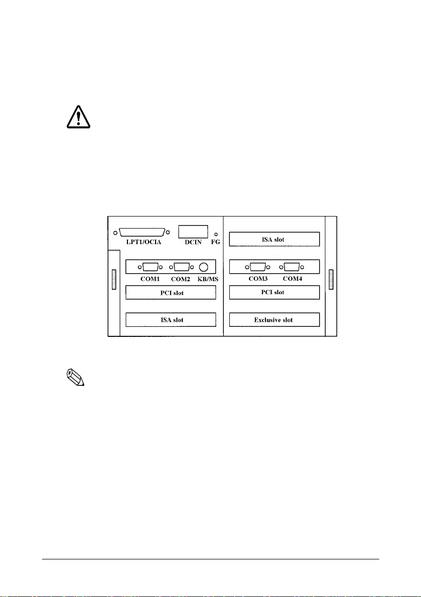
Page 11
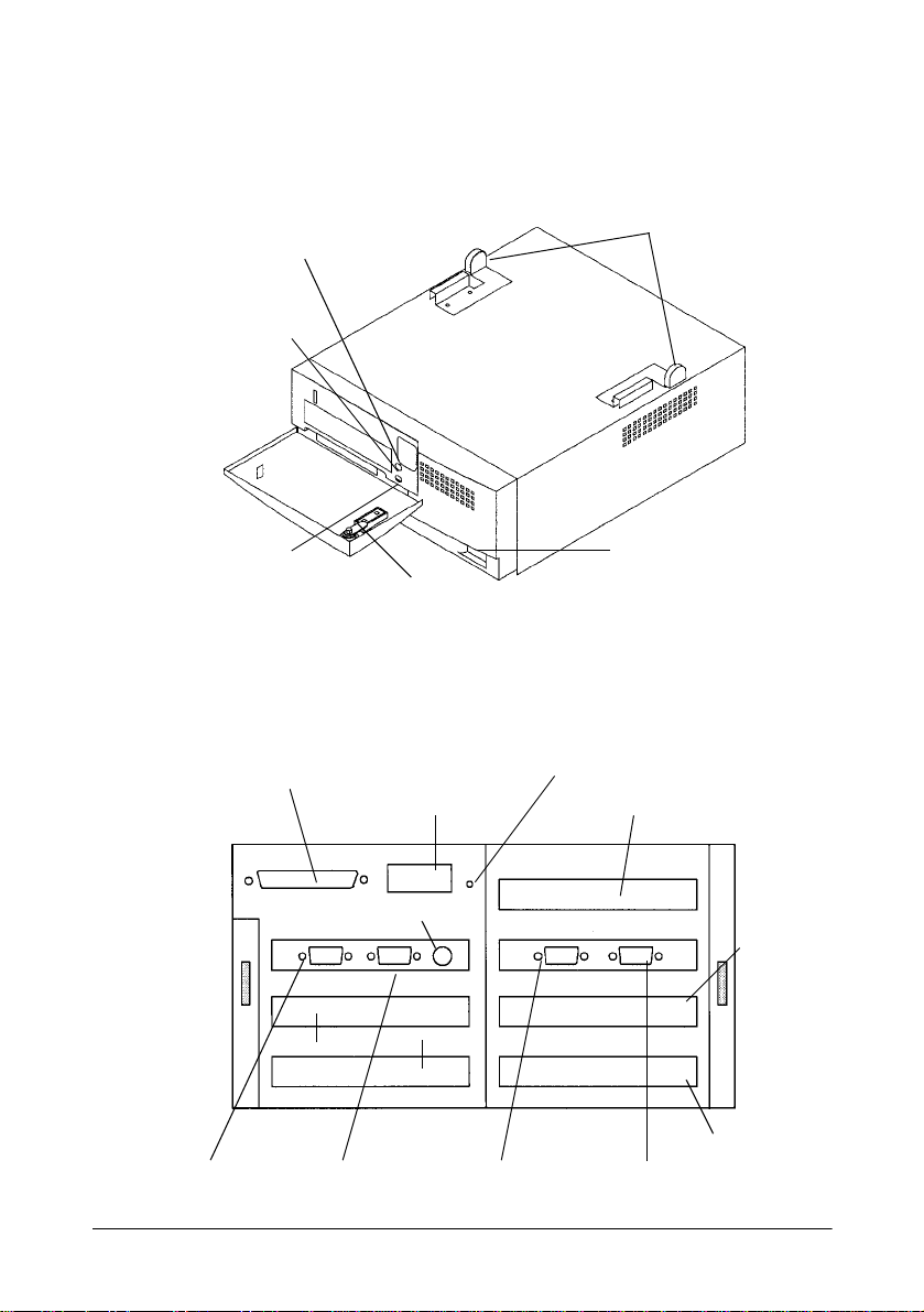
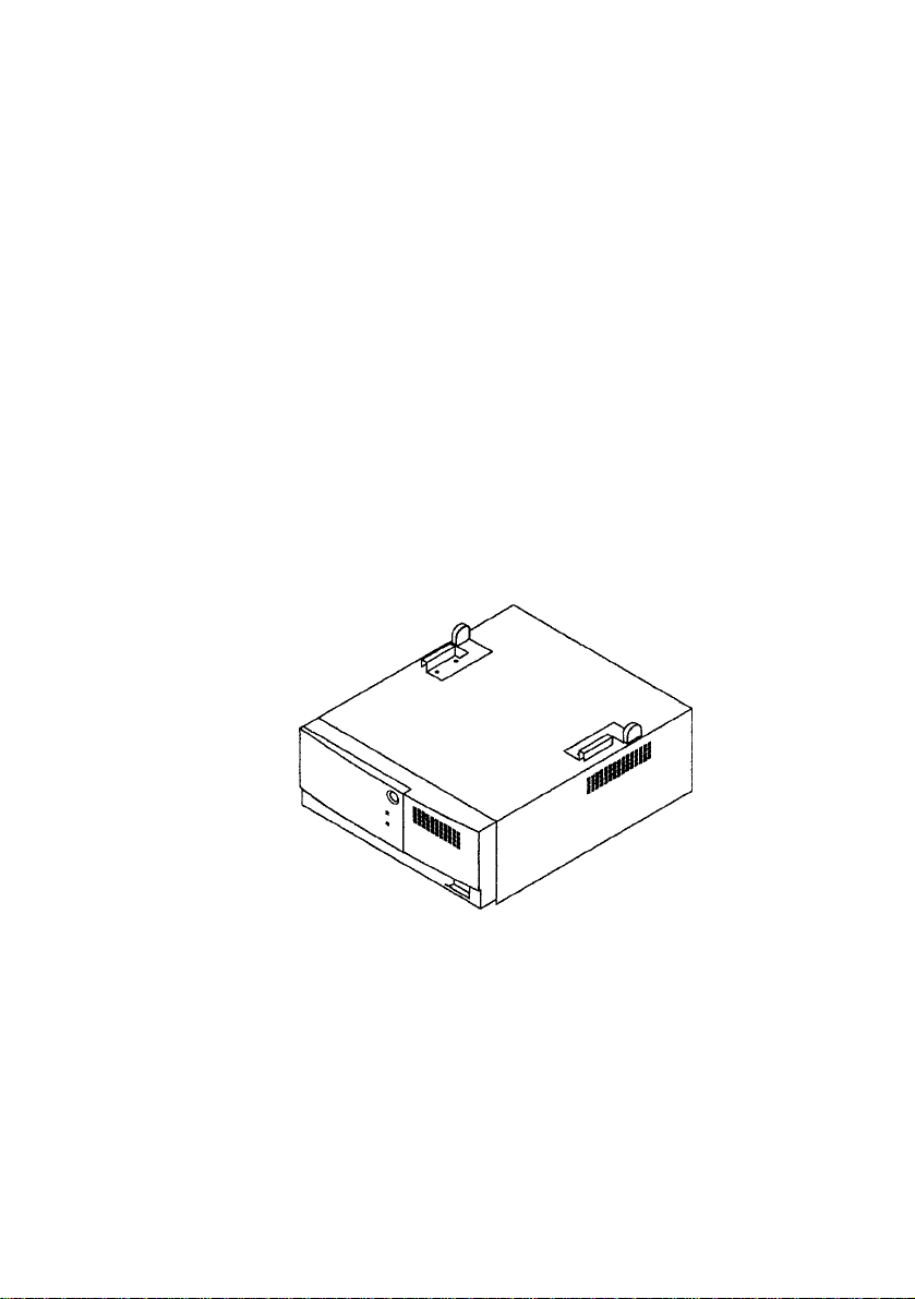
The illustration below shows the part names of the IM-505:
Printer hook
Power LED
HDD LED
Reset switch
LPT1/OCIA connector
DCIN connector
Keyboard/Mouse
PCI slot
ISA slot
COM1 COM2
Back Panel of the IM-505
Key lock
Frame Ground (Storage hole)
ISA slot
COM3
Power switch
PCI slot
Exclusive slot
COM4
Introduction 3
Page 12

Handling Guidelines
Observe these guidelines when handling the IM-505:
• Make sure you read the safety instructions for the power supply
before you attach or remove it.
• Do not block any slots or openings on t he IM-505. These are provided
for the ventilation necessary to ensure reliable operation and
protection from ov erheating.
• Make sure that any device connected to the AC outlet of the power
supply does not consume more than 200 VA.
• Make sure that the total power requirements of all the devices getting
their power from the IM-505 do not exceed the IM-505 power
limitations. See Appendix A for details.
• When you transport the IM-505 in its shipping container, make sure
you replace the transportation screw.
4 Introduction
Page 13

Option
• PCMCIA expansion module
This expansion module supports two Type I or Type II PC cards or
one Type III PC card.
Following items are also available for the IM-505:
• a 3.5-inch floppy disk drive
• a 2.5-inch hard disk drive
• SIMMs
•a CPU
• a power supply cable
• a video board
• a network adapter
• ROM chips for user programming (User ROMs)
List of Terms
The following list identifies terms used in th is manual and the
corresponding names printed on each circuit board.
Manual term Printed name on circuit board
Connector board IC board
External I/O board EX- I/O
PCMCIA expansion module PCMCIA board
Power board Power board
System board Main board
Introduction 5
Page 14

Warnings, Cautions, and Notes
Notes and precautions in this manual are identi fie d by their level of
importance, as defined below.
WARNING
Provides information that must be observed to prevent harm (not lifethreatening) to the us er.
Caution
Provides information that must be observed to prevent damage to the
equipment or loss of data.
Note:
Provides important information and useful tips on handling the
equipment.
6 Introduction
Page 15

AC Adapter Safety Precautions
This section presen ts important information intended to ensure safe and
effective use of the AC adapter. Please read this section carefully.
WARNINGS
• Shut down the IM-505 immediately if it produces smoke, a strange odor, or
unusual noise. Continued use may lead to fire or electric shock.
Immediately unplug the IM-505 and contact your dealer or a SEIKO EPSON service center for advice.
• Never attempt to repair the AC adapter yourself. Improper repair work can be
dangerous.
• Never disassemble or mo dify the AC adapter.
Tampering with this product may result in injury, fire, or electric shock.
• Be sure to use the specified power source.
Connection to an improper power source may cause fire or shock.
• Never insert or disconnect the power plug with wet hands.
Doing so may result in severe shock.
• Do not allow foreign matter to fall into the AC adapter.
Penetration of foreign objects may lead to fire or shock.
• If water or other liquid spills into the AC adapter, unplug the power cord immediately, and then contact you r dealer or a SEIKO EP SON servi ce center for ad vice.
Continued usage may lead to fire or shock.
• Do not place multiple loads on the power outlet (wall outlet).
Overloading the outlet may lead to fire.
• Always supply power directly from a standard domestic po wer outlet.
• Handle the power cord with care.
7 Introduction
Page 16

CAUTIONS
• Be sure your power cord meets the relevant safety standards and includes a
power-system ground terminal (PE terminal).
• Do not connect the AC adapter to any equipment not specified below.
Improper usage may lead to equipment damage, fire, or shock.
• Be sure to set this equipment on a firm, stable, horizontal surface.
Product may break or cause injury if it falls.
• Do not use in locations subject to high humidity or dust levels.
Excessive humidity and dust may cause equipment damage, fire, or shock.
• Do not place heavy objects on top of the AC adapter. Never stand or lean on the
AC adapter .
Equipment may fall or collapse, causing breakage and possible injury.
• To ensure safety, please unplug this product prior to leaving it unused for an
extended period.
• Do not change the fuse for yourself.
If the device that connected to the DC cable of the AC adapter does not turned
on, there may be the possibility that the fuse of the AC adapter was blown. If this
may happen, contact your dealer or a SEIKO EPSON service center for advice.
• Do not drop, bump or otherwise subject the AC adapter to strong vibration or
impact.
• Do not block the openings on the AC adapter. They are provided for the ventilation necessary to ensure reliable operation and protection from overheating.
Introduction 8
Page 17

Supported Devices
The AC adapter is intended for use only wi th the SEI KO EPSON products
listed below. Never use th e AC adapter with an unlist ed device type, as
this may lead to fire, smoke emission, or other such hazard.
•IM-505
• TM-H5000
• TM-U950
Usage and Storage Locations
The AC adapter should always be kept in a safe and stable environment,
both when in use and when in storage. In particular, keep the AC adapter
away from the following:
• Direct sunlight
• High temperature and humidity
• Extreme changes in temperature or humidity
• Heating and cooling equipment
• Volatile materials
• High levels of dust
• Locations where it might become wet
•Fire
• Vibration and impact
9 Introduction
Page 18

Connecting the AC Adapter to the Power Cord
Be sure to push the end of th e power cord all the way into the AC inlet.
The fitting on the cord should make contact with the back of the inlet.
Important Safety Rules
• Set the AC adapter so that its label side is facing up.
• Do not put the AC adapter so that the side to which the power cord or
the DC cable is connected is down.
• Do not connect to electrical outlets close to devices that generate
voltage fluctuations or electrical noise. In particular, stay clear of
devices that use large electric motors.
• Always connect th e DC cab le bef ore pl uggin g the power c ord i nto the
wall outlet.
• When disconnecting power, always unplug the power cord from the
wall outlet before disconnecting the DC cable.
• When disconnecting the DC cable, hold it firmly at the connector
area. Do not tug on the cord itself.
• To clean the unit, wipe with a dry or slightly moistened (and firmly
wrung) cloth. Never clean the unit while it is plugged into the wall
outlet.
• Note that this unit is no t equipped with an ON/OFF switch. Keep in
mind that you may need to pull the plug out of the socket in order to
cut the power in the event of a problem with the connected device.
• Observe the standard of the AC outlet.
Introduction 10
Page 19

Additional Safety Precautions for AC Adapter
• Never attempt to stretch the cords to enable a connection. The power
cord and DC cable must have adequate slack at all times during use.
• Never allow the AC adapter to hang from the power cord or DC cable.
• Do not place metallic parts (such as fasteners) in contact with the DC
cable.
• Do not connect the unit to a table tap or extension cord.
• Never clean the AC adapter with thinner, benzene, alcohol, or other
such solvent.
11 Introduction
Page 20

How to Use This Manual
You don’t have to read ev er ything in this book to set u p and con figu r e t he
IM-505; see the following chapter summaries to find the sections you
need.
Chapter 1 describes the how to set up your hardware and how to install
optional equipment such as interface cards and drives.
Chapter 2 describes the running the BIOS Setup to config ur e th e system,
establishing power management criteria, and performing device
diagnostics.
Chapter3 contains troubleshooting tips.
Appendix A lists the specifications of your IM-505.
Appendix B shows the configur ation for th e loop-ba ck connectors used to
perform loop-back tests in the device diagnostics utility.
Appendix C provides information for the SIMM.
Introduction 12
Page 21

Chapter 1
Installation
This chapter explains how to set up your hardware. For configuring your
system using the BIOS Setup, see the next chapter.
How to Use This Chapter
For a list of the components included with the IM-505, see page 1-3.
To remove the transportation screw, turn to page 1-4.
The IM module is a control unit without the cover set. Before you can
install internal compon ents or cha nge jumper sett ings, you need t o remove
the cover set from the IM module.
Check the table below to see where these procedures are described; then
follow the instructions on that page.
If you want to See page
Remove the IM modu le f rom the cover set 1-5
Once you remove the cover off from the IM module, turn to the
appropriate sections in this chapter and follow the instructions for
installing the component.
If you want to See page
Set jumper s 1-8
Install a CPU 1-14
Install a CPU Cooling Fan 1-15
Install a SIMM 1-16
Install a hard disk drive 1-18
Installation 1-1
Page 22

If you want to See page
Install a floppy disk drive 1-20
Install an ISA/PCI card 1-21
Install a PCMCIA expansion module 1-24
When you have the components installed, return the IM module to the
cover set. Then turn to page 1-27 for instructions on assembling the IM505 system.
1-2 Installation
Page 23
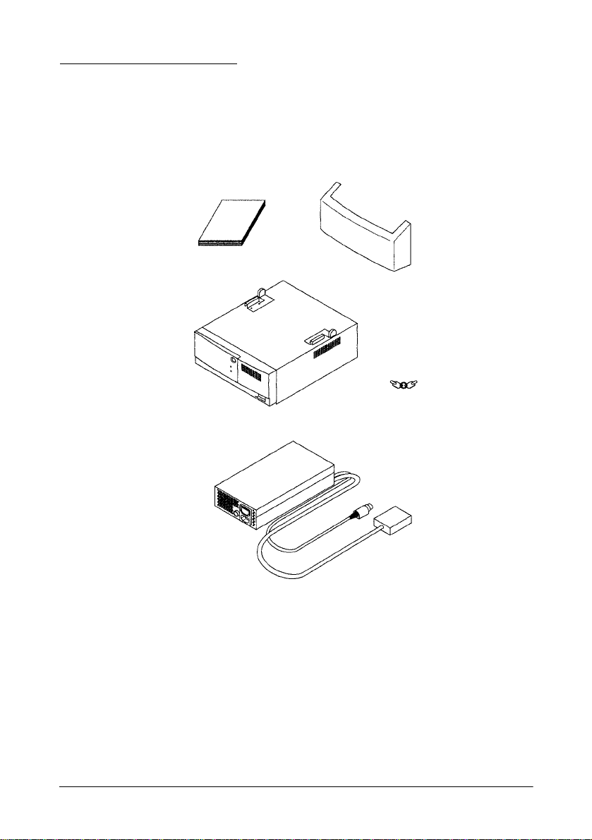
Unpacking the IM-505
When you unpack the IM-505, make sure you have these items:
User’s Manual
Back Cover
Keys (2pieces)
IM-505
AC adapter
Confirm that the package includes the items above. If any of these items
are damaged or missing, please contact your dealer for assistance. After
unpacking, save the packaging materials so that you can reuse them for
future transport.
Note that the package does not include a power cord of the AC adapter.
Please prepare an appropriate power cord before using the IM-505.
Installation 1-3
Page 24
Setting Up the IM Module
Before you perform any steps described in this section, make sure the IM
module and any peripheral devices are off. Disconnect the AC adapter
from the IM module. Also disconnect any cable s that ar e conne cte d to the
IM module.
Caution
Never install options, change jumper settings, or connect peripherals
when the IM module i s turne d on o r the AC a dapter is con nected to the IM
module.
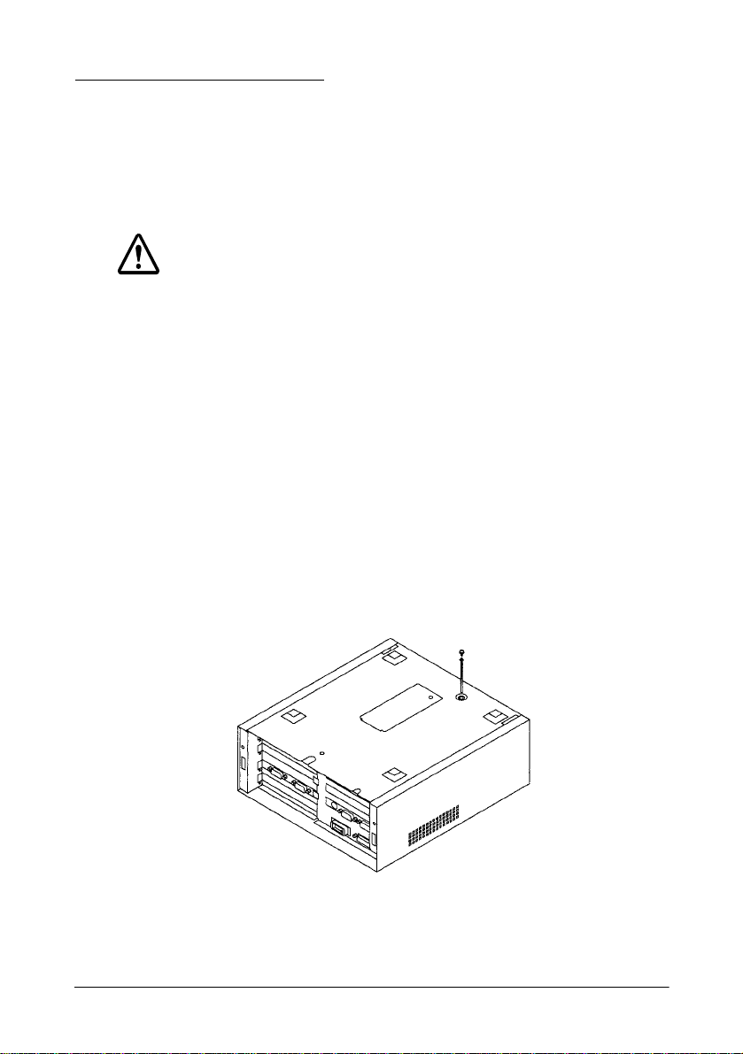
Removing the Transportation Screw
The IM module is secured to the cover set during shipping by a
transportation screw. Fo llow these steps to remove this screw:
1. Turn the IM module over so that the bottom of the IM module is
facing up; then locate the transportation screw.
2. Use a #2 phillips screwdriver to turn the screw counterclockwise and
remove it.
1-4 Installation
Page 25
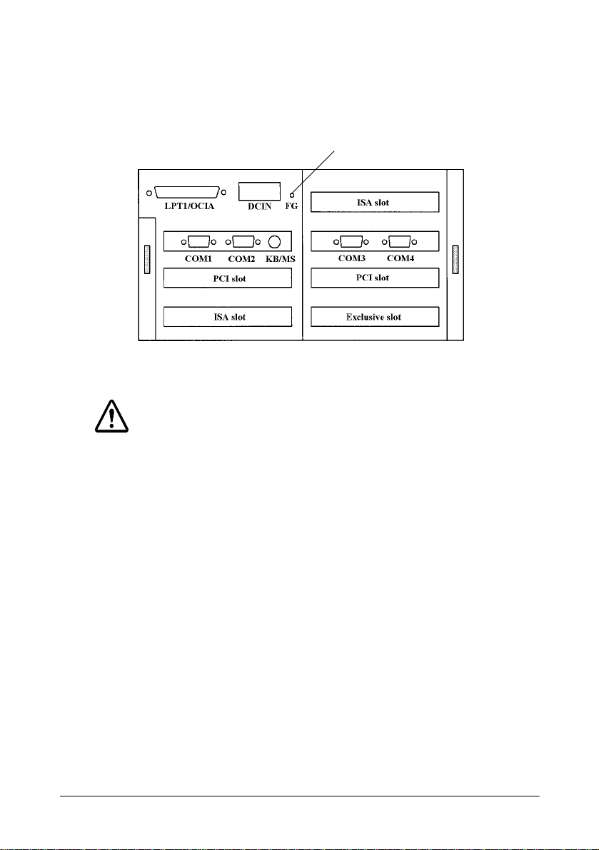
3. Locate the storage hole on the back panel of the IM module.
4. Secure the transportation screw to the storage hole (FG) in the back
panel.
Storage hole
Caution
When you transport the IM module in its shipping container, make sure
you replace the transportation screw in the bottom of the IM module.
Removing the IM Module From the Cover Set
Before you can install or remove any components from the IM module or
change jumper settings, you need to remove the IM module from t he cover
set. Follow these steps:
1. Make sure that the transportation screw has been removed. (See page
1-4.)
2. Use the key provided to open the lock on the front panel of the cover
set; then open the front panel.
Installation 1-5
Page 26
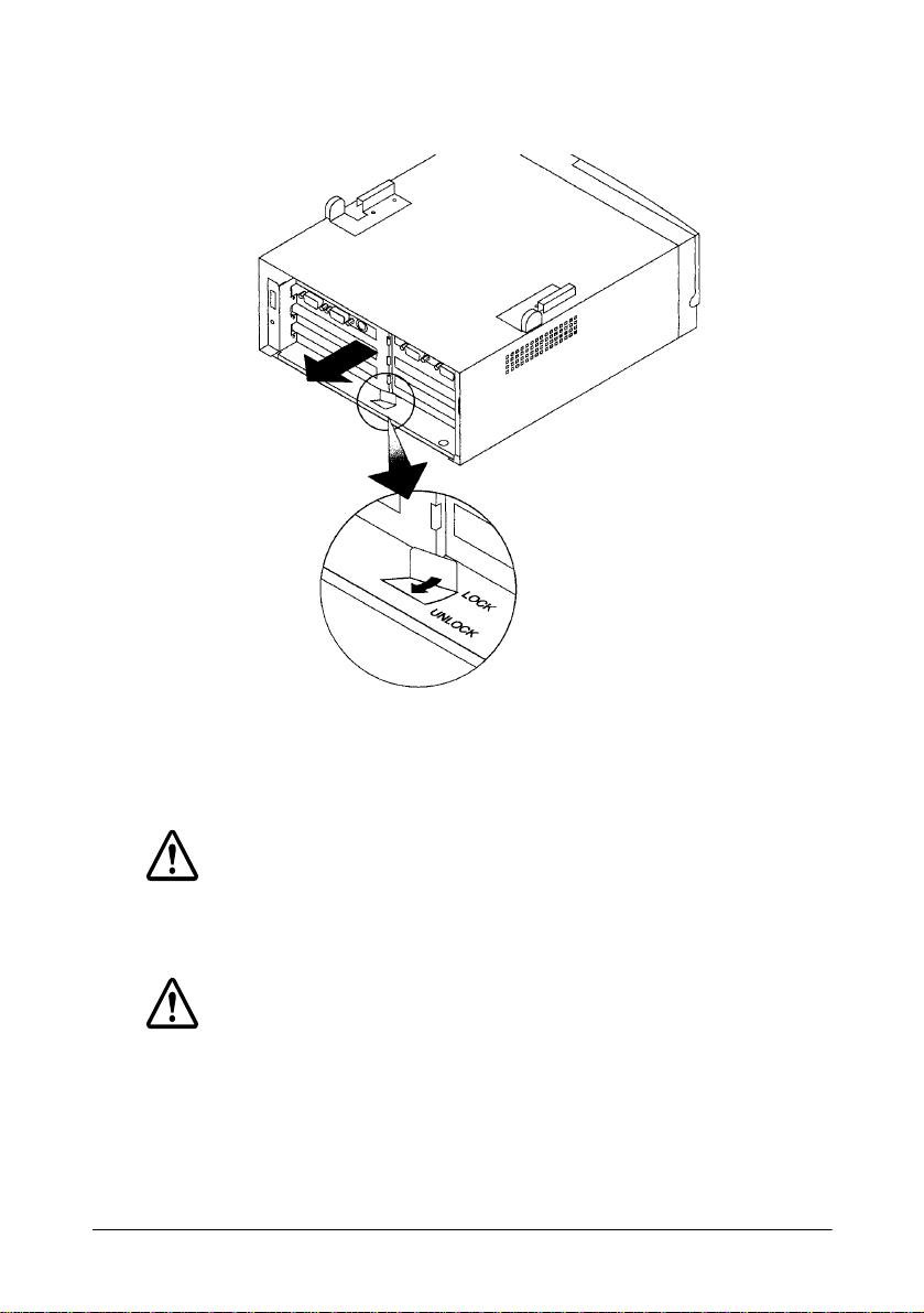
3. Set the tab on the plate lock to UNLOCK and pull the IM mo dule out,
as shown below:
When you are ready to replace the IM module in the cover set, slide it in,
until it is all the way in the cover set. Close the front panel and use the key
to lock it.
Caution
Make sure you lock the IM module to the cover set using the lock on the
front panel. The module could fall from the cover set if it isn’t secured.
Caution
Be sure to ground yourself by touching a grounded metal surface every
time you remove the cover. If you are not properly grounded, you could
generate an electric shock that could damage a component when you
touch it.
1-6 Installation
Page 27
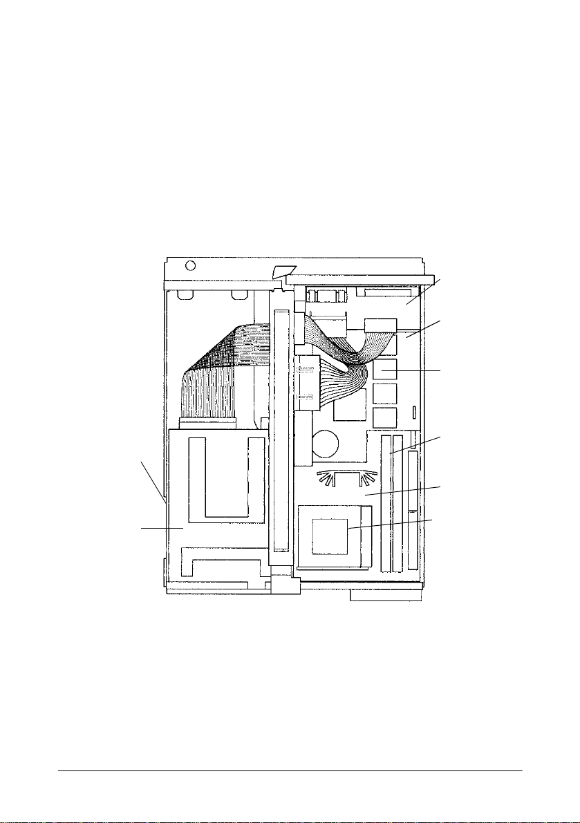
Locating Components
The following illustrati on shows the major componen ts in the IM modul e.
As you install components, refer to this diagram to locate the ones you
need.
Power board
External I/O
board
User ROM
Socket
Hard disk
drive (under
floppy disk
drive)
Floppy disk
drive
SIMM sockets
Main board
CPU socket
Installation 1-7
Page 28

Setting the Jumpers
The IM module contains three circuit boards with jumpers you can set to
control how the system operates. The following sections describe setting
the jumpers on each of these boards.
For two-pin jumpers, the jumper is either on (it connects the two pins) or
off (it doesn’t connect the two pins).
For three-pin jumpers, th e jumper setting is 1-2 when the jumper connec ts
pins 1 and 2. The setting is 2-3 when pins 2 and 3 are connected. You see
a 1 and a 3 printed on the circuit board to identify these pins.
To move a jumper from one position to another, use needle-nose pliers or
tweezers to pull it off the pins and move it to the desired position.
Caution
Be careful not to bend the jumper pins or damage any components on the
board.
1-8 Installation
Page 29

Main Board jumper settings
The main board contains seven sets of jumpers. The jumpers of the main
board determines the types of the CPU and the SIMM. Switch them as
necessary according to the CPU and S IMM config uration th at is used. Use
J13 only when the system does not start due to incorrect BIOS settings.
Use the information in the following table to change the jumpers on the
main board.
Main board jumper settings
Jumper Function Settings Description
J1, J2 BUS CLOCK switching - See table below.
J3, J4 CPU rate switching - See table below.
J9 SIMM type 1-2 EDO
2-3 (*) FPM
J10 Regulator module switch 1-2 VRE (VRM)
2-3 (*) VR
J13 Erase of the CMOS RAM setting 1-2 Erase settings
2-3 (*) Normal use
**Default setting
Installation 1-9
Page 30
Selection of the CPU Speed
CPU J1 J2 Bus Speed J3 J4 CPU Rate
75MHz ON ON 50MHz 1-2 1- 2 1.5 X
90MHz OFF ON 60MHz 1-2 1-2 1.5 X
100MHz(*) ON OFF 66MHz 1-2 1-2 1.5 X
120MHz OFF ON 60MHz 2-3 1-2 2.0 X
133MHz ON OFF 66MHz 2-3 1-2 2.0 X
150MHz OFF ON 60MHz 2-3 2-3 2.5 X
166MHz ON OFF 66MHz 2-3 2-3 2.5 X
(180MHz) OFF ON 60MHz 1-2 2-3 3.0 X
200MHz ON OFF 66MHz 1-2 2-3 3.0 X
**Default setting
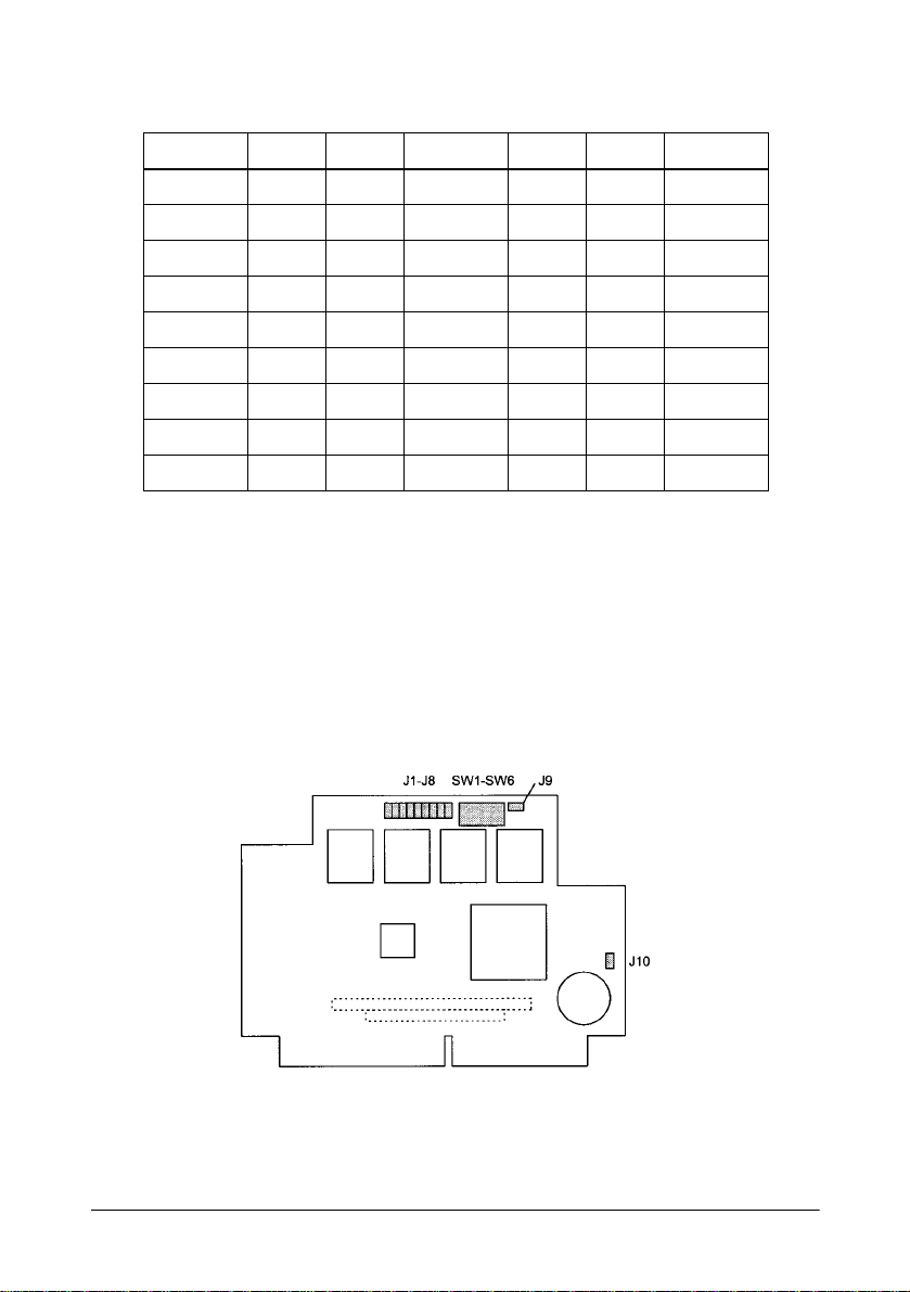
External I/O Board Jumpers and DIP Switches settings
The external I/O board contains ten jumpers and six DIP switches.
Jumpers J1 to J8 control the function for pin 1 of COM1 to COM4. The
DIP switches must be changed when the user ROM is used.
The location of the jumpers and DIP switches on the external I/O board
are shown below.
1-10 Installation
Page 31

Use the information in the following table to change the jumpers on the
external I/O board.
External I/O board jumper settings
Jumper Function Settings Description
J1, J2 COM1 (pin 1 assignment) - See table below.
J3, J4 COM2 (pin 1 assignment) - See table below.
J5, J6 COM3 (pin 1 assignment) - See table below.
J7, J8 COM4 (pin 1 assignment) - See table below.
J9 Pin 1 for use r ROM soc ke t fun ctio n 1-2 (*) VPP (1M, 2M bit)
2-3 A17 (4Mbit 5V )
J10 NVRAM backup (*) 1-2 Backup
2-3 Non backup
*Default settings
Serial port pin 1 assignment
COM1 COM2 COM3 COM4 Pin 1 Function
1-2 - 1-2 - 1-2 - 1-2 - DCD (* )
2-3 1-2 2-3 1-2 2-3 1-2 2-3 1-2 +12V
2-3 2-3 2-3 2-3 2-3 2-3 2-3 2-3 +5V
- : Do not care.
*Default settings
Installation 1-11
Page 32

External I/O board DIP switches settings
Switch Function Settings Description
SW1-SW3 User ROM control - Refer to table below.
SW4 Use of NVRAM for POS OFF Not use.
ON (*) Use
SW5 Use of user ROM for POS OFF (*) Not use
ON Use
SW6 Selection of gate array operation mode OFF Plug & Play mode
ON (*) User control mode
*Default settings
User ROM Control Settings
SW1 SW2 SW Contents
ON ON ON Normal Mode (*)
ON ON OFF Extend ROM mode, starting address C8000h
ON OFF ON Extend ROM mode, starting address D0000 h
ON OFF OFF Extend ROM mode, starting address D8000h
OFF - - Boot-strap ROM mode (BIOS ROM mode)
- : Do not care.
*Default settings
1-12 Installation
Page 33
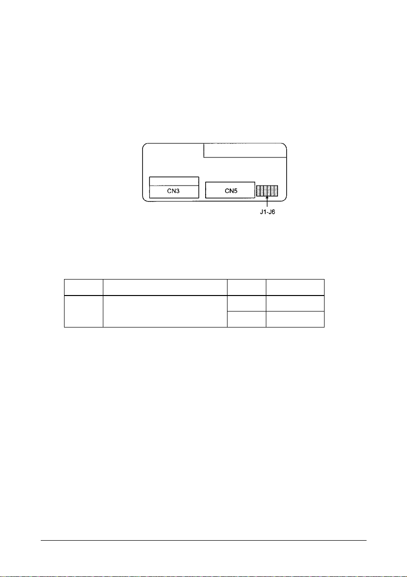
Power Board jumpers settings
Power board has six jumpers. You can insert or remove the jumpers (J1 to
J6) simultaneously. When you use the OCIA interface, switch the
jumpers.
The locations of the jumpers on the power board are shown below.
Power board Jumper settings l
Switches Function Setting Description
ON LPT1/OCIA port pin 19 -24 function 1-2 OCIA signal
ON switch 2-3 (*) GND
*Default settings
Installation 1-13
Page 34

Installing a CPU
The IM module equips the Sock et 7. Following CPU types can be insta lled
to it:
o Intel Pentium 75MHz to 200MHz
o Cyrix 6x86 (Scheduled)
o AMD K5 (Scheduled)
Caution
To avoid generating static electricity and damaging the CPU, ground
yourself by touching a grounded metal surface before you touch the CPU.
Follow these steps to install the CPU:
1. Lift the release lever of the Socket 7.
2. Align the corner cut position on the CPU and Socket 7.
3. Push down the CPU onto the Socket 7.
4. Push down the release lever and lock it.
1-14 Installation
Page 35

Installing a CPU Cooling Fan
A CPU cooling fan is included in the IM-505 package.
You must install a CPU cooling fan to the CPU to prevent the CPU from
overheating.
Follow these steps to install the CPU co oling fan:
1. Hook the hole of EIF clip to the notch on the Socket7.
2. Place the heat-sink on the CPU surface (Slide the cooling fan).
3. Push down the opposite side of EIF clip and hook up.
4. Connect the cooling fan cable to the CN7 socket.
Installation 1-15
Page 36

Installing or Removing a SIMM
The main board contains two SIMM sockets. The SIMMs must meet the
specifications in Appendix C.
Note:
You must always install two SIMMs as a pair. Their capacities and
types must be identical.
Caution
To avoid generating static electricity and damaging the SIMMs, ground
yourself by touching a grounded metal surface before you touch the
SIMMs.
Follow these steps to install the SIMMs :
1. Position the SIMM at an angle over the socket. Make sure that the
notch on the SIMM points toward the fan.
Caution
To avoid contamination, do not touch the connectors on the SIMM.
2. Push the SIMM into the socket until it is seated firmly.
1-16 Installation
Page 37

3. Tilt the SIMM until it is upright, guiding the hole at each end of the
SIMM over the retaining post at each end of the SIMM socket. If it
does not go in smoothly , do not f or ce i t ; pu ll i t al l th e wa y out and try
again.
Caution
Make sure the SIMM is properly installed and locked by the tabs on both
sides of the socket.
4. Install another SIMM as the same procedure above.
Note:
After you have installed the SIMMs, make sure the jumper settings
are correct for the type of SIMMs you installed (page 1-9).
When you want to remove the SIMM, use your fingers or a small
screwdriver to carefully pull away the metal tabs that secure the SIMM at
each end. The SIMM falls to the side. Lift it out o f the socket. Make sure
you store the SIMM in an anti-static bag.
Installation 1-17
Page 38

Installing a Hard Disk Drive
You can install a 2.5-inch hard disk drive (0.74 inch high) in the IM
module. An mounting bracket and an adapter board must be attached to
the hard disk drive.
Caution
Handle the hard disk drive gently. Small shocks or vibrations could
damage the drive.
Follow these steps to install the hard disk drive assembly:
1. Slide the drive assembly into the chassis so that the notches along the
bottom of the assembly are under the chassis tabs.
Caution
To avoid contamination, do not touch the drive connectors.
2. Push the drive assembly in gently until you feel the connector fit in to
place.
1-18 Installation
Page 39

3. Secure the mounting bracket to the IM module with the retaining
screw, as shown below.
To remove the hard disk drive, remove the screw that secures the
mounting bracket to the IM module chassis. Then pull the hard disk drive
straight out of the chassis.
Installation 1-19
Page 40
Installing a Floppy Disk Drive
You can install a 3.5-inch floppy disk drive in the IM module. A spacer
FDD and two cables must be attached to the floppy disk drive.
Follow these steps to install the floppy disk drive assembly:
1. If necessary, remove th e floppy disk d rive slo t cover at the front o f the
IM module. Remove the screw securing the slot cover to the chassis
then lift the slot cover out. Stor e the slot cover in c ase you remove the
floppy disk drive later.
2. Mount the floppy disk drive assembly into the notch of the frame
FDD, then push the drive assembly towards the front face to meet
each screw hole of the FDD and frame FDD.
3. Hold the drive assembly in place as you secure it with retaining
screws.
4. Connect the floppy disk drive cables to the connectors as shown
below.
Note:
After you have installed a floppy disk drive, run the BIOS Setup and
use the Diskette A: option to set the size of the drive.
To remove the floppy disk drive, reverse the steps above.
1-20 Installation
Page 41

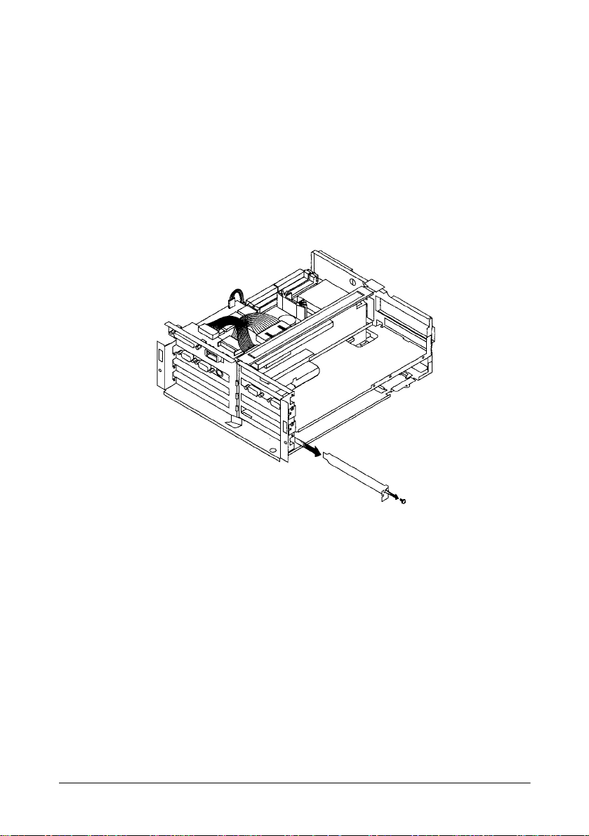
Installing an ISA/PCI Card
You can install up to two ISA cards in the ISA expansion slots. You also
can install up to tw o PCI cards in the PCI expansion slots
As the IM-505 does n ot have t he on-bo ard video f unction , you must install
either an ISA video board or a PCI video board before you use the IM-
505.
The maximum size of the ISA/PCI cards are as follows:
Length Width
Max. size 240mm (9.4inch) 107mm (4.2inch) 12mm (0.47inch) 10mm (0.39inch)
Height
(Parts side)
Height
(Solder side)
Caution
When you connect the ISA/PCI card, make sure t he drawing current of the
card does not exceed the capacity limits shown in Appendix A.
Installation 1-21
Page 42

1. Remove the retaining screw securing the slot cover, as shown below.
(Keep the screw to secure the ISA/PCI card to the IM module.)
2. Slide the slot cover out and set it aside. Store the slot cover in case
you remove the ISA/PCI card later.
Caution
To avoid contamination, do not touch the card connectors.
1-22 Installation
Page 43

3. Gently guide the card the connector as shown below:
Push the card in firmly (but carefully) to insert it fully. You should
feel the connectors fit into place. If the card does not go in smoothly,
no not force it; pu ll it all the way out and try again.
4. Secure the end of the ISA/PCI card to the IM module with the
retaining screw.
If you want to remove the ISA/PCI card, remove the retaining screw
securing the card. Pull the ca rd straight out of the slot, then replace the slot
cover.
Installation 1-23
Page 44
Installing a PCMCIA Expansion Module (option)
You can install an optional PCMCIA expansion module in the exclusive
slot on the connector board. The PCMCIA expansion module can support
two Type I or Type II cards or a single Type III card.
1. Remove the retaining screw securing the exclusive slot cover to the
IM module, as shown below. (Keep the screw to secure the PCMCIA
expansion module to the IM module.)
2. Slide the slot cover out and set it aside. Store the slot cover in case
you remove the PCMCIA expansion module later.
1-24 Installation
Page 45

3. Push both sides of the PCMCIA sl ot cover inside the cover, and
remove it.
Caution
To avoid contamination , do not touch t he connect ors on the PCMCIA
expansion module.
4. Gently guide the PCMCIA expans ion module into the bottom
connector, as shown below:
Installation 1-25
Page 46

Once the connectors on the PCMCIA expansion module reach the
slot, push them in firmly (but carefull y). You should feel them f it into
place. If the expansion module does not go in smoothly, do not force
it; pull it all the way out and try again.
5. Secure the end of the PCMCIA expansion module to the IM module
with the retaining screw.
6. Find the PCMCIA slot cover you removed in step 3.
7. Insert the tab on one side of the PCMCIA slo t co ver in to the notch on
the PCMCIA expansion module; then push the tab on the other side
into place.
Caution
When you connect the PC card(s), make sure the drawing current of the
card(s) does not exceed the capacity limits shown in Appendix A.
Note:
You need to remove the PCMCIA slot cover before you install or
remove the PC cards.
Caution
Make sure you always attach the slot cover to the PCMCIA expansion module. The
slot cover discharges the static electricity in your body. If you do not attach the cover,
the IM module could lo ck up when you insert or remove th e PC cards.
Note:
If you use MS-DOS or Windows 3.1, you need to install card and
socket services software on your IM module before it can recognize
PC cards in the slots on the PCMCIA expansion module.
If you want to remove the PCMCIA expansion module, remove the retaining
screw securing the PCMCIA expansion module to the IM module. Pull the
expansion module straight out of the slot and replace the slot cover.
1-26 Installation
Page 47

Setting Up the IM-505 System
This section describes the following:
o Conneting the TM pr inter.
o Attaching the AC adapter.
o Attaching the back cover.
Before you perform any steps described in this section, make sure you
have completed any of the following that apply
o Installed the components you need and set any necessary jumpers in
the IM module.
o Replaced the IM module in the cover set.
Make sure the IM-505 is turned off and the AC adapter is disconnected.
Caution
Never connect peripherals when the IM-505 is turned on or the AC adapter is
connected to the IM-505.
Installation 1-27
Page 48

Connecting the TM Printer
Following TM printer can be connected to the IM-505:
o TM-H5000
o TM-U950
For setting up the TM printer itself, see the operator’s manual for the TM
printer.
Follow these steps to connect the TM printer:
Note:
You need an appropriate interface cable. The interface cable is not
enclosed with your IM-505 package.
1. Set the TM printer o n the IM-505 so that the printer ho ok s fit into the
hollows of the TM printer.
1-28 Installation
Page 49

2. Connect the interface cable to the TM printer referring to the
operator’s manual of the TM printer.
3. Connect the other end of the interface cable to the IM-505 (usually to
the COM 1 port).
4. Connect the DC cable of the AC adapter to the TM printer.
Installation 1-29
Page 50
Connecting Peripherals
You can connect various peripherals to the IM module using the
connectors on the back panel.
Caution
See Appendix A for power limitations for any device that draws its power
from the IM module.
Note:
For some peripherals, you may need to change the jumper settings.
See page 1-8 for more information.
1-30 Installation
Page 51

Connecting the AC Adapter
The AC adapter that came with the IM module contains a DC cable
connector that connects to t he 2 4 VDC c onnector on the back panel of the
IM module. Follow these steps to connect the AC adapter:
Note:
Note that the package does not include a power cord of the AC
adapter. Please prepare an appropriate power cord befo re using th e
IM-505.
1. Make sure you read the safety instruction within this manual.
2. Connect the DC cable connector of the AC adapter to the 24 VDC
connector on the IM-505. Push the connector in as far as it will go.
3. Connect the power cord to the AC adapter.
4. Insert the other end of the power cord into an electrical outlet.
See Appendix A for additional information on the AC adapter.
Installation 1-31
Page 52

Attaching the Back Cover
The IM-505 comes with a back cover that provides a protective covering
for your cables. After you have connected all the peripherals to the IM505, attach the back cover. Insert the tabs on one side of the cover first;
then push the tabs on the other side into place.
back cover
Caution
Never lift the IM-505 by the back cover. This cover cannot support the
weight of the IM-505, so it could drop.
1-32 Installation
Page 53

Charging the Batteries
Lithium Battery
The IM-505 contains a rechargeable Lithium battery that backs up the
real-time clock and the CMOS RAM data. The Lithium battery is not
charged fully at the f actory. You need to charge t he batt ery before y ou use
the IM-505 for the first time. If you have not used the IM-505 for a long
time, you still need to charge it.
Follow these steps to charge the battery:
Caution
Charge the Lithium batte ry before you first use t he IM-505 . You must also
charge it if you have not used the IM-505 for a long time. If the Lithium
battery is not ful ly charged, your system configuration settings in the
CMOS RAM may be incorrect when you start the IM-505.
1. Connect the AC cable of the AC adapter to the IM-505.
2. Turn on the power swi tch of the IM-505. The Lithium battery is
charged when the power LED light is on.
The Lithium batt ery i s bein g cha rged wh en the IM-505 is bei ng turn ed on .
Use the following table for time of charging.
Time for full charge 40 hours or more (from factory condition)
Backup time 30 days or more (with full charge)
Installation 1-33
Page 54

Chapter 2
Using System Utilities
The IM-505 comes with the following utility pro grams in the System
ROM:
o BIOS Setup, for defining the configuration of the system.
o Device Diagnostics, for troubleshooting devices attached to the IM-
505.
You see a prompt to access BIOS Setup and Device Diagnostic s each time
you start the IM-505.
These programs and the factory default optio ns for th is I M-505 are stored
in the ROM. New configuration settings are stored in CMOS RAM, which
is backed up by a battery.
Using the BIOS Setup
The BIOS Setup defines how the system is configured. You need to run
this program the first time you conf igure the IM-505. You may nee d to run
it again if you change the configuration.
Caution
Do not change the setting values not described here. If you change them,
there may be the possibilities th at the IM-505 will not work. If this
happen, run the BIOS Setup and press F9 key (Setup Default).
Using System Utilities 2-1
Page 55

Starting the BIOS Setup
To start the BIOS Setup:
1. Turn on or reboot your IM-505. Following message will be
displayed:
Press <F2> to enter SETUP.
2. Press F2 to display the Main Menu of the BIOS Setup. If the
Supervisor password is set, you must enter it here.
Menu Bar
The Menu Bar at the top of the windows lists these selections:
MAIN - Use this menu for basic system configuration.
Advanced - Use this menu to set the Advanc ed Features avai lable on your
system’s chip set.
Security - Use this menu to set User and Supervisor Passwords.
Power - Use this menu to configure Power Management features.
Exit - Exits the current menu.
Use the left arrow key or right arrow key to make a selection.
2-2 Using System Utilities
Page 56

Legend Bar
Use the keys listed i n the l egend bar on the bot tom to make your select ions
or exit the current menu. The chart below described the legend keys and
their alternates:
Legend Keys
Key Function
General Help window (See below).
F1
Esc
Left arrow/Right arrow
Uparrow/Down arrow
or
Tab
Shift-Tab
or
Home
PgU
F5
F6
F9
F10
Enter
Alt-R
p or
or
-
or + or
End
PgDn
Space
Exit this menu.
Select a different m enu.
Move cursor up and down.
Cycle cursor up and down .
Move cursor to top or bottom of wind ow.
Move cursor to next or previous page.
Select the Prev ious Value for the fie ld.
Select the Next Value for the field.
Load the Default Configuration values for this m en u.
Load the Previous Configuration values for this me nu.
Execute Command or Select P Submenu.
Refresh screen.
To select an item, use the left arrow and right arrow keys to move the
cursor to the field you want. Then use the plus and minus keys to select
a value for the field. The Save Changes commands in t he Exit Menu save
the values currently displayed in all the menus.
To display a sub menu, use the arrow keys to move the cursor to the sub
menu you want. Then press Enter. A triangular pointer marks all sub
menus.
Using System Utilities 2-3
Page 57

Field Help Window
The help window on the right side of each menu displays the help text for
the currently selected field. As you move the cursor to each field, it
updates the values .
General Help Window
Pressing F1 or Alt-H on any menu brings up the General Help window
that describes the legend keys and their alternates:
The scroll bar on the right of any window indicates that th ere is more than
one page of information in the window. Use PgUp and PgDn to di splay
all the pages. Pressing Home and End displays the first and last page.
Pressing Enter displays each page and then exits the window.
Press Esc to exit the current window.
Main Menu Selections
You can make the following se le c tions on the Main Menu itself. Use the
sub menus for other selections.
Feature Options Descriptions
System Time N/A Set the system time. Enter the new date
System Date N/A Set th e s y s tem date. Enter the new date
Diskette A: 1.44MB, 3 1/2
2.88MB, 3 1/2
Not Installed
360KB, 5 1/4
1,2MB, 5 1/4
720KB, 3 1/2
in hour:minutes:seconds format
in month/day/year format.
Select the type of flop py di sk dri ve
installed in your system.
2-4 Using System Utilities
Page 58

Main Menu - IDE Adapters 0 Master
Selecting IDE Adapters 0 Master on the Main Menu displays the IDE
Adapters 0 master menu.
The IDE adapters control the hard disk drives.
None
. If the hard
Use a separate sub menu to configure the hard disk drive.
Feature Options Descriptions
Autotype Fixed
Disk
Type Auto
N/A Pressing
None
1 to 39
User
attempt to detect th e type of hard di sk. If
successful, it fill s in the re maining f ields
on this menu.
Set the hard disk type. If the hard disk is
not installed , s et to
disk is installed, genera ll y set to
causes the syst em to
Enter
Note:
If you do not install hard di sk dri ves, set Type to None. It saves boot
time.
Main Menu - Boot Sequence
Auto
.
Selecting Boot sequence on the Main Menu displays the Boot option
menu.
Feature Options Descriptions
Boot sequence: A: then C:
C: then A:
C: only
SETUP prompt: Enabled
Disabled
POST Errors: Enabled
Disabled
Sets the order system searches drives for
a boot disk.
Displays "
during bootup.
At boot error, pauses and displays
"
Press <FI> to resume, <F2> to
Setup
Press <F2> to enter Setup
".
"
Using System Utilities 2-5
Page 59

Feature Options Descriptions
Floppy check: Enabled
Summary screen: E na bled
Keyboard
connection check:
Disabled
Disabled
Enabled
Disabled
Seeks-diskette drives duri ng bootup.
Disabling speeds boot time.
Displays system summary screen during
bootup.
Checks the keyboard connection during
bootup.
Main Menu - Numlock
Selecting Keyboard Features on the Main Menu displays the Keyboard
Features menu.
Feature Options Descriptions
Numlock Auto
Key Click Disabled
Keyboard autorepeat rate
Keyboard autorepeat delay
On
Off
Enabled
30/Sec
26.7/Sec
21.8/Sec
18.5/Sec
13.3/Sec
10/Sec
6/Sec
2/Sec
1/2 Sec
3/4 Sec
1 Sec
1/4 Sec
Select Power-on state for Num lock.
Turns on or off audible key cl ic k.
Sets the numb er of times a second to
repeat a key stroke when you hold the
key down.
Set the delay time after the key is he ld
down before it begins to rep ea t th e key
stroke.
2-6 Using System Utilities
Page 60

Advanced Menu Selections
Selecting Advanced from menu bar on the Main Menu displays the
Advanced Menu.
You can make the following selections on the Advanced Menu itself. Use
the sub menus for other selections.
Feature Options Descriptions
Plug & Play OS No
Reset
Configuration
Data
Large Disk
Access Mode
Yes
No
Yes
DOS
Other
Do not change the settings of this feature
even if you use the W indows 95 on this
machine.
There may be the case that "
System Configuration Data - run
configuration utility
when the IM-505 is booted. In this case,
rebooting the IM-505 setting this feature
to
initializes the Plug & Play d ata.
Yes
After rebooting the IM -505, this setting
will automa tically return to
Select Other
system such as UNIX or OS/2, and the
HDD does not work correctly.
if you use the operating
Invalid
" will be displayed
No
.
Advanced Menu - Integrated Peripherals
Selecting Integrated Peripherals on the Advanced Menu displays the
Integrated Peripherals menu:
The menu sets up the connections between the CPU and the I/O ports
(COM: and LPT:), the floppy disk, and the hard disk controllers.
Using System Utilities 2-7
Page 61

Feature Options Descriptions
COM port1 3F8, IRQ4
2F8, IRQ3
3E8, IRQ11
2E8, IRQ10
3E8, No IRQ
2E8, No IRQ
338, IRQ11
238, IRQ10
Auto
Disabled
COM port2 Same as above.
Default settings are 2F8,
IRQ3.
COM port3 Same as above.
Default settings are 3E8,
IRQ11.
COM port4 Same as above.
Default settings are 2E8,
IRQ10.
LPT port1: 378, IRQ7
278, IRQ7
378, IRQ5
278, IRQ5
3BC, IRQ5
Auto
Disabled
LPT port2: Same as above.
Default settings are 278 ,
IRQ5.
LPT 1 Mode Output Only
Bi-Directional
EPP
ECP
ECP Mode DMA 3
0
1
Serial port settings.
When Auto is selected, PnP BIOS
selects the settings automatically.
Change the settings when other devices
such as internal modem use the serial
port.
Same as above.
Same as above.
Same as above.
Parallel port settings.
When Auto is selected, PnP BIOS
selects the settings automatically.
Parallel port settings (OCIA interface
exclusive). If you do not use the OCIA
interface, set t o Disabled.
Mode setting of the parallel port 1.
DMA setting when the paralle l po rt 1 is
set to the ECP mode. This value has no
meanings when the para ll el port 1 is set
to other mode.
2-8 Using System Utilities
Page 62

Feature Options Descriptions
Diskette
controller 2:
Integrated IDE
Adapter 2:
Mouse interrupt IRQ12
Custom Chip I/O
address:
Enabled
Auto
Disabled
Primary
Secondary
Auto
Disabled
Auto
Disabled
280
350
220
320
Auto
Disabled
Set to
Disabled
on-board floppy disk co ntroller. Do not
change this setting when you use it.
Set to
Disabled
on-board IDE controller. Do not change
this setting when you use it.
Interrupt setting when you use the PS/2
mouse. Set to
use the PS/2 mouse.
I/O address sett ing of the custom ga te
array for NVRAM for POS and User
ROM. Change this setting when other
device uses this address.
when you do not use the
when you do not use the
when you do not
Disabled
Security Menu Selections
Selecting Security from menu bar on the Main Menu displays the
Security Menu.
Enabling Supervisor Password requires a password for entering Setup.
The passwords are not case sensitive.
Pressing Enter at either Set Supervi sor Password or Set User Password
displays a dialog box.
Type the password and press Enter. Repeat the same operation.
You can make the following selections on the Security Menu itself.
Using System Utilities 2-9
Page 63

Feature Options Descriptions
Supervisor
Password
Set User
Password
Password on boot Disabled
N/A Pressing
N/A Pressing
Enabled
entering the supervisor password. This
password gives full access to SETUP
menus. To erase the password, press
only
Enter
for entering the user password. This
password gives restricted access to
SETUP menus. Requires prior setting of
Supervisor password. To erase the
password, press only
Enabled requires a password on boot.
Requires prior setting of the Supe rvi sor
password. If supervisor password is set
and this option
user is booting.
You must set this setting to
enable the user password.
displays dialog box for
r
Ente
.
displays the dialog box
Enter
Enter
, BIOS assumes
disabled
Power Menu Selections
Selecting Power from menu bar on the Main Menu displays the Power
Menu.
.
Enabled
to
Use this menu to specify your settings for power management. A power
management system reduces the amount of energy used after specified
periods of inactivity.
You can make the following selections on the Po wer Menu itself.
2-10 Using System Utilities
Page 64

Feature Options Descriptions
Power
Management
Mode
Fixed Disk
Timeout
Customize
Max. Power Savings
Med. Power Savings
Min. Power Savings
Disabled
16 min
2 min
4 min
6 min
8 min
12 min
Max., Med., and Min. set powermanagement op tions with pre-defined
values. Select Customize to make your
own selections from the followi ng
fields. Disabled turns off all powe r
management.
Inactivity period of fixe d di sk required
before standby (motor off ).
Using System Utilities 2-11
Page 65

Using Device Diagnostics
The Device Diagnostics utility included in the system ROM of the IM 505 lets you isolate communication problems the IM-505 or connected
devices may be having. You can use these diagnostics to test the
following:
o TM printer operation test
o DM display indication test
o Cash drawer operation test
o Serial port loop-back test
o LPT1 port loop-back test
o OCIA port loop-back test
o Printing test of printer which is connected to LPT1
2-12 Using System Utilities
Page 66

Device Diagnostics Utility Conditions
The Device Diagnostics Utility runs under the following conditions.
Device Diagnostics Utility Conditions
Setting Condition
Connection to the TM printer The TM printer needs to be connected to the IM-505.
Connect the print er to either COM1 to COM4 or
LPT1 even if you will not test the TM prin ter.
Setting of the TM printer DIP switches Set the receiving buffer to maxi m um.
Setting of DIP switch of the DM
displays
Set selection switch, which is the customer display
connection/non-connection, to non-c onnection. (If it
has a selection switch).
Set up the setting on com mu nication to follow the
instruction, if the TM printer does not have the ID
function. (ESC/POS GSI command).
Baud Rate: 9600 bps
Word Length: 8 bits
Parity: None
Refer to the manual of the TM printer for the setting
procedure.
o When the TM prin ter connects to COM1.
Set up the setting on com mu nication to follow the
instruction, when the TM printer which has the ID
function (ESC/POS GS I command).
Baud Rate: S am e setting as the TM printer
Word Length : S ame setting as the TM printer
Parity: Same setting as the TM printer
Set up the setting on com mu nication to follow the
instruction, when the TM printer which does not have
the ID function (ESC/POS GS I command).
Baud Rate: 9600 bps
Word Length: 8 bits
Parity: None
o When the TM printer connects another port
except COM1.
Set up the DM display the setting on communication
to follow the instruction.
Baud Rate: 9600 bps
Word Length: 8 bits
Parity: None
Refer to the DM display manual for the setting
procedures
Using System Utilities 2-13
Page 67

Starting Device Diagnostics
When you start the IM-505, you see the following prompt for a few
seconds.
Press F10-Key to start device diagnostics.
When you see the prompt, press F10. You see the following dialog box
when you start the Device Diagnostics Utility.
Select TM Port
COM1
COM2
COM3
COM4
LPT1
None
Select the port which is co nnect ed to the TM printer, using the up arrow
or down arrow key; then press ENTER.
You see the Device Diagnostics screen.
Device Diagnostics uses a series of menu bars, pull-down menus, and
dialog boxes that allow you to select options or perform diagnostic tests.
Follow these guidelines for using Device Diagnostics:
o To display a pull-down menu, use the left arrow or right arr ow key
to highlight the option; then press Enter (if necessary).You can also
see the pull-down menu if you press the key which cor responds to the
initial letter of the option. (The Initialize option does not have a
pull-down menu.)
o To select an option from the pull-down menus, use the up arrow or
down arrow key to highlight the option; then press Enter. If the
option has a dialog box, you see it when you press Enter.
o Press Esc to close a pull-down menu or a dialog box.
o Press the back-space key to correct typing.
2-14 Using System Utilities
Page 68

Device Diagnostics Screen
The Device Diagnostics screen is divided into the following areas:
o TM/Drawer
oDM
o COM ports
oLPT1/OCIA
o Messages.
TM/Drawer
The TM/Drawer area of the Device Diagnostics screen displays the
communication settings, cash drawer driving pulse signal width and the
status for the TM printer and cash drawer.
TM/DM information
Setting Description
TM Model Displays the model name depending on the type of TM printer attached
to the IM-505.
TM Port Displays the TM printer co nne ction support which was selecte d whe n
TM Reset Signal Indicates the signal and signal definition the IM-505 is using to reset the
Baud Rate Indicates the baud rate Device Diagnostics is using to communicate with
Word Length Indicates the word length Device Diagno sti cs is using to communicate
Parity Indicates whether Device Diagnostics is using parity to communicate
Drawer On Time Displays the pulse width of sig nal for opening the cash drawer .
TM Status Indicates the status of the TM printer. See the table called “TM status
Drawer Status Displays the status (High/Low) of the cash drawer.
you started the Device Dia gnostics Utility.
TM printer. You see
reset signal.
the TM printer and DM display.
with the TM printer.
with the TM printer.
messages” for a description of these messages.
here because the IM-505 does not have a
None
Using System Utilities 2-15
Page 69

TM status messages
Message Priority Description
Disable – The port connected to the TM printer is disabled. Set to Enabled
using the BIOS Setup.
No communication
Hardware error 1 The print head is overheated, or the printer is not working.
Paper feeding 2 The TM printer is feeding paper.
Receipt end 3 The receipt pa per path contain s no pa per.
Journal end 4 The journal paper path contai ns no pa per.
Paper near-end 5 The pap er roll dia me t er i s too small or is not installed.
– o Displays this message when a TM printer that does not have
ID function (ESC/POS GS I command) is connected. Check
whether DIP switches of the TM printer are set to the
following.
Baud Rate: 9600 bps
Word Length: 8 bits
Parity: None
Although the screen indicates “No communication,” the
Device Diagnostics Utility can communicate to the TM
printer if the DIP switches are set up correctly. If something
is wrong, check the TM s tatus messages.
o Device Diagnostics Utility cannot communicate to the TM
printer when a TM printer that has ID function (ESC/POS
GS I command) is connected.
Check the follow ing items:
o T he interface cable and power cable i s c onnected
properly to the TM printer.
o Make sure you turn off the IM-50 5 be fore you connect
the cable.
o T he TM printer power switch is on.
o The TM printer, that was selected when Device
Diagnostics Utility started is connected to the port.
o T he TM printer is not performing a self-test when
Device Diagnostics Utility starts.
o A paper feed switch is not pressed when Device
Diagnostics Utility starts.
If the TM printer does not m ee t these conditions, cor rect the
problem and select t he Initialize optio n from the menu bar.
If the printer meets all the above conditions, one of the following
may have occurred:
o The print head has overheat ed.
o The TM printer is not working.
2-16 Using System Utilities
Page 70

TM status messages (Continued)
Message Priority Description
Receipt nearend
Journal nearend
Cover open 8 The printer cover is open.
On-line 9 The printer is on-line. T he TM print test is possible.
* If Device Diagnostics detect s more than one TM status, it displays the highest priorit y
message. (Priority code 1 is hi ghe r than priority code 3.)
6 The receipt paper roll diame t er is too small or is not installed .
7 The journal paper roll diameter is too small or is not instal led.
DM
The DM area on the screen indicates the communication settings and the
status of the DM display.
DM Information
Setting Description
DM port Indicates the port that the Device Diagnostics Utility uses to
transmit data.
Baud Rate Indicates the Baud Rate that the Device Diagnostics Utility uses
to communicate to the DM display.
Word Length Indicates Word Length t hat the Device Diagnostics U ti li ty use s
Parity Indicates whether Device Diagnostics Utility uses parity to
DM status Indicates DM status. Refers to "DM Status Message", which has
to communicate to the DM display.
communicate to DM display.
explanations of these messages.
Using System Utilities 2-17
Page 71

DM status messages
Message Description
Disable COM port A is not set to 3F8h. Set COM port A to 3F8h in the
System Configuration U ti li ty .
No communication Device Diagnostics is not able to communicate with the DM display.
Busy DM display’s co nd ition is busy. It is possibly caused by the
Ready The DM display is ready to receive data. The DM display test is
Check the TM printer a nd DM di splay for the following:
o The DM display is properly connect ed. Make sure you turn off
the IM-505 before you connect the cable.
o The data communications DIP switch is the same for the DM
display and the TM printer. Make sure you turn off the IM -505
before you change the settings.
o DM display power switch is on.
o DM display is not executing a s el f test.
If DM display does not meet these conditions, correct the probl em
and select the Initia lize option from the me nu ba r.
If the TM printer and DM displ ay meet the above conditions, one of
the following may hav e oc curred:
o DM display interface circuit on the IM-505 is not working.
o The DM display is not working.
following;
o DM display is running a self test.
o After the Device Diagnostics Utility starts, the DM display
power was turned off.
possible.
COM port information
The COM ports area of the screen lists the DTR, DSR, RTS, CTS, DCD,
and RI status for each of the available COM ports. When the port is
disabled, you see a message to that effect.
2-18 Using System Utilities
Page 72

LPT1/OCIA information
The LPT1/OCIA area of the screen lists the -BSY, -ACK, PE, SLCT, and
-ERR status for the LPT1 port, an d the RDT, -CLI, SDT, and
-CLO status for the OCIA port. When the port is disabled, you see a
message to that effect.
Messages
The message portion of the screen displays the result of tests.
Message area
Test category Message Description
TM printer Disable The port is disabled.
Done The TM pr inter test is completed . Check the printin g
motion and auto cutter motion.
DM display test Disabled The port is disabled.
Done DM displa y test is completed. Check indication.
Drawer kick-out test Disabled The port is disabled.
Done The Drawer kick-out test is completed. Check the
Loop-back test Error The diagnostics test failed. This message also appears
Disabled The port is disabled.
motion of cash drawer.
when a loop-back conne ct or is not connected or the
wrong loop-back conn ec tor is connected.
Ok The test completed successfully
LPT1 print test Time out The printer connected to the LPT1 port did not enter a
Disabled The port is disabled.
Ok The print data was sent successfully.
ready state after 2 seconds.
Using System Utilities 2-19
Page 73

Using the Setup Menu
The Setup menu allows you to set the length of time for the voltage signal
supplied to the solenoid of the cash drawer to open it.
Setting the Drawer ON time
The Drawer ON time option sets the length of time required for the
voltage signal to pass through the solenoid to open the cash drawer.
To set the time, select the Drawer ON time option from the Setup pulldown menu. You see a dialog box allowing you to enter th e ON time your
cash drawer requires. You can enter a value up to 500 (ms). For the
appropriate value, see your cash drawer manual.
Running Device Tests
The Device-Tests option on the menu bar allows you to run the following
tests:
o TM print test
o DM display test
o Drawer kick-out test
o COM1 loop-back test
o COM2 loop-back test
o COM3 loop-back test
o COM4 loop-back test
o OCIA loop-back test
o LPT1 loop-back test
o LPT1 print test.
2-20 Using System Utilities
Page 74

Note:
Before you perform the loop-back tests, you need to connect an
appropriate loop-back connect or to the port . See App endix B for the
loop-back connector configurations.
TM print test
The following tests a r e executed during the TM print test:
o Receipt print test, which prints a standard print pattern
o Auto cutter test (for a printer equipped with an auto cutter only)
Note:
Before you run the test, make sure the TM status message says online. If it doesn’t, see "TM Status Message".
When the test is complete, make sure the standard print pattern printed.
For the printer which has an auto cutter , make sure that the auto cutt er cuts
the receipt.
DM display test
The DM display test sends the following message to the DM display:
Display Module Test
***** Device Diagnostics *****
Note:
Before you run the DM display test, make sure the DM status
message says Ready. If it doesn't, see Table on page 2-17.
Check the DM display screen to see if the test has been performed.
Using System Utilities 2-21
Page 75

Drawer kick-out test
The drawer kick-out test opens the cash drawer. If the cash drawer opens,
the test was successful. The TM printer has two drawer kick-out drive
signals: signal 1 (pin 2) and signal 2 (pin 5). However, this test checks
only for the drawer kick-out drive signal 1.
If you set a password for the drawer kick-out test (page 2-15), you see the
following prompt when you select Drawer kick-out test from the
menu bar:
Enter
Type your password and press Enter. Device Diagnosti cs tries to open the
cash drawer.
Note:
Before you run the drawer kick-out test, make sure the TM status
message says on-line. If it doesn't, see Table on page 2-15.
COM ports, OCIA, and LPT1 loop-back tests
The following loop-back tests are available:
o The COM port test checks the DTR, DSR, CTS, RTS, TXD, and RXD
signals.
o The LPT1 port test checks the -STROBE, -ACK, DATA0, BUSY, -
AUTO FEED, PAPER EMPTY, -ERR, -INIT, -SELECT IN, and
SELECT signals.
o The OCIA port test checks the -CLOCK OUT, -SD ATA, RETURN, -
CLOCK IN, RDATA RETURN, and -RDATA sig nals.
Note:
Before you run these tests, make sure that the port you want to test is
enabled and that the approp riate l oop-back connecto r is a ttached t o
the port.
2-22 Using System Utilities
Page 76

When the tests complete successfully, you see ok in the Message area of
the screen. If the test failed, you see an error message.
LPT1 print test
The LPT1 print tes t prints a standa rd prin t pattern on the pr inter con nected
to LPT1. If the printer is busy, you se e the time-out message in the
Message area of the screen.
Note:
Before you run the LPT1 print test, make sure the LPT1 port is
enabled. Also make sure that an appropriate printer is connected to
the LPT1 port.
Initializing Device Diagnostics
When you select Initialize from the menu bar, Device Diagnostics
restarts the program. If Device Diagnostics displays No
communication for the TM status of TM/Drawer area or DM status of
DM area, fix the problem. Then select this opt ion to reset the program. See
Table 2-3 and Table 2-4 for more information.
Leaving Device Diagnostics
When you select Exit from the menu bar, the system quits Device
Diagnostics and restarts the IM-505.
Using System Utilities 2-23
Page 77

Chapter 3
Troubleshooting
The IM-505 has been designed with reliab ility in min d. If, however, if you
encounter any difficulties using this IM-505, read this chapter. The first
section provides error messages for diagnost ics the system runs during th e
power-on self test (POST). This section is followed by some general
troubleshooting guidelines for the system.
Troubleshooting 3-1
Page 78

Messages
Message List
Message Description
Diskette Drive A error
Diskette Drive B error
Entering SETUP........ The SETUP Utility is entering
Extended RAM Failed at offset :nnnn The extended RAM is corrupted at offset :
Extended RAM P as s ed nnnn KB RAM check is terminat ed.
Failing Bits:nnnn At the address : nnnn the me mory (system,
Fixed Disk 0
FailureFixed Disk 1
FailureFixed D i sk Controller Failure
Incorrect Drive A type - run SETUP The floppy disk drive (A) setting is incorrect .
Incorrect Drive B type - run SETU P The flop py di sk dri ve (B) setting is incorrect.
Invalid System Configuration Data The data for PnP must be initialized. Run
Invalid NVRAM media typ e The error occurred in access to NVRAM
Keyboard controller error The error occurred in the keyboard controller
Keyboard error The keyboard may be corrupted.
Keyboard error nn The key at code : nn may be corrupted.
Keyboard locked - Uncli ck key swi tc h Release the key lock to opera te the keyboard.
Monitor type does not match CMOS - Run
SETUP
nnnn Shadow RAM Passed The nnn KB shadow RAM check is
The disk drive error occu rred at the drive A
(drive B).Check whether the disk type setting
is correct and the dri ve is inst al led correctly
through the SETUP Utility.
nnnn or the settin g is incorrect.
extended, shadow) error occurred.
The hard disk is corrupted or the setting is
incorrect check whe the r the hard disk is
installed correctly a nd the hard disk type
setting is correct through the SETUP Utility.
Run the SETUP Ut il ity.
Run the SETUP Ut il ity.
SETUP Utility and set Advanced - Reset
Configuration Data t o Yes an d reboot.
(CMOS)
test. Replace the keyboard or the keyboard
controller.
The monitor type setting is incorre ct . Run the
correct setting through the SET UP Utility.
terminated.
3-2 Troubleshooting
Page 79

Message List
Message Description
Operating system not fou nd The operat ing system is not found. Check
whether the hard disk and drive A setting is
correct.
Press (F1) to resume,(F2) to Setup This massage is al so found after error
message which can be recovered.Depress the
F1 key, the opera tion restarts.Depress the F2
key, the SETUP Utility runs.
Press (F2) to enter SETUP This message is found in the self diagnostic
Previous boot incomple te - Default
configuration used
Real time clock error The real-time clock error occurred. The board
Shadow Ram Failed at offset:nnn The shadow memory may be corrupted at
System battery is dead - Re pl ac e and run
SETUP
System BIOS shadowed The shadow BIOS is copied to the shadow
System cache error - Cache disabled The cache memory error occurred.The cache
System CMOS checksum bad - run SET UP The setting may be updat ed incorrectly
System RAM Failed at offset:nnnn The system memory may corrupted at offset :
test.
The self diagno s ti c test does not terminate
correctly.The default configuration must be
loaded. Run the SETUP Utility to check the
setting. If the setting is incorrect, the unit may
not run correctly. This error is cleared at the
next running.
may be corrupted.
offset : nnn on the setting is incorrect.
The battery may be corru pte d. Charge the
battery, and the correct setting must be done
through the SETUP Utility.
RAM.
is disabled
through the CMOS.The correct setting must
be done through the SE TUP Ut ility.
nnnn or the setting is incorre c t.
Troubleshooting 3-3
Page 80

Message List
Message Description
System time error The timer test error occurred.The board may
be corrupted.
UMB upper limit segment address:nnnn The address : nnnn shows UMB upper limit
Video BIOS shadowed The video VIOS is copied to the shadow
segment.
RAM.
The IM-505 Will Not Start
The power light is on, but the IM-505 does not start.
Check monitor problems on page 3-6. Also, start the system from a
bootable floppy disk . Make su re th e hard d isk drive typ e is set co rre ctly in
the BIOS Setup. Also make sure the hard d isk dri ve i s correctl y format ted
and contains an operating system.
The IM-505 does not start and the power light is not lit.
Make sure all cables are securely connected to the IM-505 and the
external power supply. Also check that the power cord is completely
plugged into the electrical outlet. Test the outlet to see if it is supplying
power.
You have installed or removed components and now the IM-505 does not
start.
Check to make sure you have reconnected all the internal and external
cables correctly.
3-4 Troubleshooting
Page 81

Also, make sure that any device connected to the AC outlet of the power
supply does not consume more than 150 VA or that the total power
requirements of all t he devices gett ing their po wer from th e IM-505 do not
exceed the system’s power limitations. See Appendix A for the power
limitations.
You may have incorrectly installed the SIMM. If the system does not
detect memory, it do es not st art. Check that the S IMM is secure ly inst alled
in the socket and that the j umpers are set correctly for the memory you’ve
installed.
The IM-505 Always Stops at Bootup
If the IM-505 always shows “Invalid System Configuration Data” at
bootup, run BIOS Setup and c hange Advanced - Reset Confi guration Data
to Yes, then reboot.
The IM-505 Does Not Respond
The IM-505 locks up.
Wait a few minutes; if the IM-505 still doesn’t respond after a reasonable
length of time, press Ctrl Alt Del. If that doesn't work, press the reset
switch.
You reset the IM-505, but it still does not respond.
Try turning the IM-505 off and on again.
The IM-505 Shuts Down
You may be drawing more power than th e IM-505 can provi de. Make sure
the combined power requirements for all the devices drawing power from
the IM-505 do not exceed the power limits listed on page A-9.
Also, the temperature inside the IM-505 may be too hot.
Troubleshooting 3-5
Page 82

Keyboard Problems
The screen displays a keyboard error message when you turn on or reset
the IM-505.
Make sure the keyboard is securely connected to the keyboard port, and
that no pins in the connector are bent or missing.
The items that appear on the screen do not correspond to the keyboard
options.
Your keyboard may not be mapped properly for the system. See if a
standard PC/AT keyboard with a PS/2 connector works.
Monitor Problems
There is no display on the screen.
Check that the monitor is turned on and plugged in.
Also, the IM-505 may be in a power management standby or suspend
mode. Press a key on the keyboard to see if anything appears on the
display.
The power switch is on, b ut the power light is not on.
Check the electrical outlet for power.
The monitor power light is on, but nothing appears on the screen.
Check the brightness and contrast controls on the monitor.
Make sure the monitor is securely connected to the IM-505.
If you are running an application program, see if you need to set up the
program for the type of display you are using.
3-6 Troubleshooting
Page 83

The EPSON DM-D Display Problems
The display is not working.
Make sure the display is the correct type (DM-D102 or DM-D203) and
that it is plugged into the DM display port on the TM printer.
Check that the DM display power switch is turned on and that its data
communications DIP switch set t ings are p roperl y se t. Also , p erform a self
test on the DM display to ensure that it is working correctly.
Check that the COM port settin g for the IM-505 is correct in the BIOS
Setup. Also make sure the flat cable on the IM-505 is properly connected.
Floppy Disk Problems
You see a floppy disk error message.
Reinsert the floppy disk, making sure to insert it all the way. If that
doesn’t solve the problem, insert it in a floppy disk drive on another IM505 to see if the drive is faulty.
Check that the floppy disk is properly formatted and is not writeprotected. Also, try copying the files to a new floppy disk or running
CHKDSK or a similar utility to repair the files.
Floppy Disk Drive Problems
A newly installed floppy disk drive is not working properly.
Make sure you have installed the drive correctly and check the cable
connection. Make sure the connector is completely closed. Run the BIOS
Setup to configure the system for the correct type of drive.
The drive is making loud or unusual noises.
Make sure the screws that secure the drive to the IM-505 are tight.
Troubleshooting 3-7
Page 84

Hard Disk Drive Problems
A newly installed hard disk drive is not working properly.
Make sure you have installed the dr ive correctly. Al so check that the drive
has been fully inserted into the connector.
Run the BIOS Setup and make sure that the system is auto-sensing the
correct drive type.
You are unable to store data on the hard disk drive.
Make sure the drive is partitioned and formatted correctly for the
operating system.
You notice a reduction in drive performance.
The data on the disk may have become fragmented. Back up all your data
and use a disk optimization utility to reorganize the files on the disk.
If you are seeing read/write er rors, the drive may hav e a physical probl em.
Replace the drive.
TM Printer Problems
The TM printer isn’t working.
Make sure the TM printer interface cable and power cable are properly
connected to both the printer and the connector on the IM-505.
Check that the TM printer pow e r switch is on.
Make sure the paper roll is installed properly in the printer.
Perform a self test on the printer to ensure that it is wo rking correctly.
Check that the printer DIP switch settings are set properly.
Note:
For print quality and paper handling problems, see the
troubleshooting chapter in the TM printer operator’s manual.
3-8 Troubleshooting
Page 85

Serial Port Problems
A device attached to a serial port is not working.
Make sure the cable is connected securely. Make sure the COM ports are
set properly in the BIOS Setup Utility.
If the device is powered externally, make sure the outlet is providing the
appropriate power. If the device is powered from the IM-505, make sure it
is not overloading the power supply. Also, make sure the voltage jumpers
for the port are set correctly. (See page 1-11.)
Check any DIP switches or control panel settings on the device to ensure
they are set correctly.
Parallel or OCIA Port Problems
A device attached to the LPT1/OCIA port is not working properly.
Make sure the device has power and is properly connected to the IM-505.
Make sure J1 and J6 on the Power Board are set to 2-3 if you are using a
parallel device or to 1-2 if y ou are us ing an OCIA devi ce or both a para llel
and an OCIA device.
If you are using an OCIA device, make sure the cable you are using has
the proper cable configuration.
Cash Drawer Problems
The cash drawer isn’t opening correctly.
Make sure the drawer is properly connected to the drawer kick (DK)
connector on the TM printer.
Check the connection of the interface cable and power cable of the TM
printer.
Check that the TM printer pow e r switch is on.
Troubleshooting 3-9
Page 86

Also, check the TM printer operator’s manual to verify that the drawer is
supported.
PC Card Problems
A PC card installed in the PCMCIA expansion module is not working.
Try reinserting the card. Then make sure the PCMCIA expansion module
is installed correctly. Also, make sure the card and socket services
software is installed correctly. Chec k that the correct PCMCIA driv ers and
utilities are installed. The supplied card and socket services software
supports most PC cards, but some do require special drivers or software.
See the documentation that came with the card for more information.
Port 80h Diagnostic Codes
The POST provides diagnostic codes to port 80h in the system. If you
install a Port 80 card in the ISA slot, you can pinpoint where an error has
occurred by reading the last code sent to the port. Port 80 cards typically
have a row of LEDs that let you read the hex codes.
Beeps indicate that short beeps are generated for the number in sub group.
The following table lists the possible port 80h diagnostic codes.
Diagnostic Codes
Code Beeps Description
02 Verify Real Mode
04 Get CPU type
06 Initialize system hardware
08 Initialize chipset registers with initial POST values
09 Set in POST flag
0A Initialize CPU regis ters
0B Enable CPU cache
0C Initialize caches to initial POST values
3-10 Troubleshooting
Page 87

Diagnostic Codes
Code Beeps Description
0E Initialize I/O
0F In it ialize the local bus IDE
10 Initialize Po w e r M anagement
11 Load alterna te registers with initial POST va lues
12 Restore CPU control word during warm boot
14 Initialize key boa rd controller
16 1-2-2-3 BIOS ROM checksum
18 8254 timer initialization
1A 8237 DMA controller initialization
1C Reset Programmable Interrupt Controller
20 1-3-1-1 Test DRAM refresh
22 1-3-1-3 Test 8742 Keyboard controller
24 Set ES segment register to 4GB
28 Autosize DRAM
2A Clear 512K base RAM
2C 1-3-4-1 RAM failure on address line
2E 1-3-4-3 RAM failure on data bits
30 1-4-1-1 RAM failure on data bits
32 Test CPU bus-clock frequency
34 Test CMOS RAM
35 Initialize al ternate chipset re gisters
36 Warm start shut down
37 Reinitializ e the chipset (MB on ly)
38 Shadow system BIOS ROM
39 Reinitialize th e cache (MB only)
3A Autosize ca che
3C Confi gure advanced chipset registers
xxxx *
xxxx
of low byte of memory bus *
xxxx
of high byte of memory bus *
Troubleshooting 3-11
Page 88

Diagnostic Codes
Code Beeps Description
3D Load alternate registers with CMOS values
40 Set initiali ze CPU speed
42 Initialize interrupt vectors
44 Initialize BIOS inte rrupts
46 2-1-2-3 Check ROM copyright notice
47 Initialize mana ge r for PCI Option ROMs
48 Check video configura tion against CMOS
49 Initialize al l video adapters in sys tem
4A Initialize al l video adapters in sy s te m
4B Display Quiet Boot screen
4C Shadow video BIOS RO M
4E Display copyright notice
50 Display CPU type and speed
51 Initialize EISA board
52 Test keyboard
54 Set key click if enabled
56 Enable keyboard
58 2-2-3-1 Test for unexpected inte rrupts
5A Display prompt “Press F2 to ente r SETUP”
5C Test RAM between 512 and 640k
60 Test extended memo ry
62 Test extended memory address lines
64 Jump to UserPatch1
66 Configure advanced cache registers
68 Enable external a nd CPU caches
6A Display exter nal cache size
6C Display shadow message
3-12 Troubleshooting
Page 89

Diagnostic Codes
Code Beeps Description
6E Display non-disposabl e segments
70 Display error messages
72 Check for configura ti on errors
74 Test real-time clock
76 Check for keyboard er rors
7A Test for key lock on
7C Set up hardware interrupt vect ors
7E Test coprocessor if present
80 Disable onboard I/O ports
82 Detect and install external RS232 ports
84 Detect and inst all external parallel ports
85 Initialize PC-com pa tible PnP ISA devices
86 Re-initialize on boa rd I/ O ports
88 Initialize BIOS Da ta Area
8A Initialize Extended BIOS DA TA A rea
8C Init ialize floppy control l er
90 Initialize hard disk controller
91 Initialize local-bus hard disk contro ll er
92 Jump to UserPatch2
93 Build MPTABLE for multi-processor boards
94 Disable A20 address line
95 Install CD-ROM for boot
96 Clear huge ES segment registe r
98 1-2 Search for option ROMs. One long, two short beeps on checksum
9A Shadow option ROMs
9C Setup Power Management
9E Enable hardware interrupts
failure.
Troubleshooting 3-13
Page 90

Diagnostic Codes
Code Beeps Description
A0 Set time of day
A2 Check key lock
A4 Initialize typematic rate
A8 Erase F2 prompt
AA Scan for F2 key stroke
AC Enter SETUP
AE Clear in-POST flag
B0 Check for errors
B2 POST done - prepare to boo t opera ting system
B4 1 One short beep before bo ot
B6 Check password (optional)
B8 Clear global descriptor table
BC Clear parity check ers
BE Check screen (optiona l)
BF Check virus and back up re minders
C0 Try to boot with INT19
D0 Interrupt handler error
D2 Unknown interrupt error
D4 Pending interrupt error
D6 Initialize optio n ROM e rror
D8 Shutdown error
DA Extended Bl ock Mode
DC Shutdown 10 erro r
The followings are for boot blo ck in Fla s h ROM
E2 Initialize the chipset
E3 Initialize refresh counter
E4 Check for Forced Flash
3-14 Troubleshooting
Page 91

Diagnostic Codes
Code Beeps Description
E5 Check HW status of ROM
E6 BIOS ROM is OK
E7 Do a complete RAM test
E8 Do OEM in it ialization
E9 Initialize interrupt controller
EA Read in the bootstrap code
EB Initialize all vectors
EC Boot the Flash program
ED Initiali ze the boot device
EE Boot code was read OK
*: If the BIOS detects error 2C, 2E, or 30 (ba se 512KB RAM error), it displays an addit io nal
word-bitmap (
xxxx
) indicating the address line or bits th at failed.
Troubleshooting 3-15
Page 92

Appendix A
IM-505 Specifications
CPU and Memory
CPU Socket 7 is equipped.
Following CPUs are available:
Intel: Pentium 75 MHz to 166MHz
(200MHz scheduled)
(Cyrix: 6x86 scheduled.)
(AMD: AMD K5 scheduled.)
Power management Advanced Power Management BIOS controls
power management functions for the CPU and
hard disk drive; functions controlled through
the BIOS setup.
On board memory None.
Second cache memory None.
SIMM sockets Two 72-pin SIMM sockets are provided on the
main board. The SIMMs must meet the
specifications in Appendix C.
System ROM System BIOS and Advanced Power
Management BIOS located in 128KB flash
ROM on the main board. System ROM ca n be
changed to 256KB flash ROM.
User ROM Four 32-pin PLCC sockets are provided (for
flash memory, 2MB maximum).
NVRAM for PnP Battery back up SRAM 32KB. 16KB is used
for the BIOS. 16KB is not used.
NVRAM for POS Battery backup SRAM 32KB.
Control Unit Specifications A-1
Page 93

Clock/calendar Real-time clock, calendar, and CMOS RAM
contained in the RTC chip; backed up by a
vanadium-lithium battery
Chipset OPTi VIPER-M
Controllers
Keyboard Keyboard controller supports any IBM/PC-A T
compatible mini-DIN keyboard.
Main Board I/O Super I/O controlle r on main board support s up
to two serial ports with FIFO, a parallel port
interface, an IDE hard disk drive interface, and
one floppy disk drive.
External I/O Board Super I/O controller on the external I/O board
supports up to two additional serial ports with
FIFO and an OCIA port.
Video On-board video function not supported.
Insert a commercially available video
board in the PCI or ISA slot to obtain the
required video functions. Video
specification depends on the board.
Interfaces
Parallel (LPT1)/OCIA The parallel interface connector can be set to
support OCIA or not through jumpers; see
page 1-13.
The parallel port can be defined as an ECP, an
EPP, a bidirectional or a unidirectional
(sending) interface using the LPT Port
MODE option in the BIOS Setup.
A-2 Control Unit Specifications
Page 94

Serial Four serial ports; COM1 and COM2 are
supported from the I/O controller on the main
board while COM3 and COM4 are supported
from the I/O controller on the external I/O
board; 9-pin D-sub male connectors
Keyboard IBM PC/AT compatible keyboard interface
built in the main board; A PS/2 type mouse can
be connected by using the branch connector.
PS/2 type 6-pin, mini DIN female connector
ISA expansion slots Two standard 16-bit, half size [length 240 mm,
width 107 mm, height 12 mm (parts side) 10
mm (solder side)] I/O expansion slots, ISA
AT-compatible, 7.2 MHz bus speed, with a
card-edge connector
PCI expansion slots Two standard 32-bit, half size [length 240
mm, width 107 mm, height 12 mm ( part s si de)
10 mm (solder side)] I/O expansion slots with
a card-edge connector.
PCMCIA expansion slot One expansion slot for a PCMCIA expansion
module supporting two Type I or II PC cards
or one Type III PC card; half-pitch card edge
connector.
One front expansion slot for a PCMCIA is also
equipped. (Front PCMCIA board for the front
expansion slot is scheduled.)
Speaker Internal; interface on main board; no volume
control
Floppy disk drive One mount availabl e for a 3.5-inch flop py disk
drive having 720KB or 1.44MB storage
capacity.
Control Unit Specifications A-3
Page 95

Hard disk drive One mount available for a 2.5-inch hard disk
drive [19 mm maximum] with IDE/E-IDE
controller conforming to MCC standards.
Security
Key lock The front key lock secures the front panel to
the IM-505 making the floppy disk drive
inaccessible and securing the IM-505 to the
cover set.
Passwords Two types of passwords defined within the
BIOS Setup ---one for booting the system and
the other for accessing the BIOS Setup.
Switches
Power switch Rocker-typ e switch turns system power on and
off; controls the TM printer (if it uses power
from the IM-505 exclusive AC adapter),
customer display, and any device (such as a
monitor) connected to the AC outlet on the
power supply
Reset switch Push-type switc h to reset the IM-505;
accessible using a pointed object like a ballpoint pen ; devices at tached to COM ports are
not reset when you reset the IM-505.
Indicators (LEDs)
Power Power indicator indicates that the IM-505 is
turned on.
A-4 Control Unit Specifications
Page 96

HDD indicator HDD indicator indicates accessing the hard
disk drive (when the hard disk drive is
installed).
FDD indicator FDD indicator indicates accessing the
floppy disk drive. FDD indicator is
attached to the floppy disk drive.
System Utilities
BIOS Setup Configures the IM-505, saving
settings to CMOS RAM; accessible by
pressing F2 when you turn on the IM-505.
Device Diagnostics Helps you to isolate communication problems
Utility the IM-505 or connected devices may be
having. You see a prompt to access Device
Diagnostics each time you start the IM-505.
AC adapter
The power supply for the IM-505 is equipped with an exclusive AC
adapter which can supply +24V to a T M print er connect ed to the I M-505.
This can normally be used r egardl ess o f th e i npu t vol ta ge. AC output (for
the CRT) is also supplied in the circuit with the po w er supply switch of
the main unit at a voltag e that is the same as the input. The AC output is
not produced when the system is off or the main unit is not connected.
Control Unit Specifications A-5
Page 97

Electrical Characteristics of the AC adapter are as follows:
Electrical Characteristics of the AC Adapter
Input Conditions Input Voltage (ratings)
Frequency (ratings) 50/60 Hz
Input current (ratings)
Power On/Off control
DC Output
Conditions
AC output for a
monitor
3-pin plug
Output voltage
Output current (rating s )
Output power (ratings)
Output peak current
16-pin plug
Output voltage:
Output current (rating s )
Output power (ratings)
Output voltage:
Output current (rating s )
Output power (ratings)
Output voltage:
Output current (rating s )
Output power (ratings)
Output voltage:
Output current (rating s )
Output power (ratings)
Input voltage (ratings)
Frequency (ratings)
Input current (ratings)
90 (100 - 10%) VAC to
264 (230 + 15%) VAC
3Hz
±
180 VA or less (except for AC
output)
Controlled with PSWI and PSWO
signals from the IM-505 .
±
±
±
5%
±
10%
10%
±
3Hz
±
3%
5%
+24VDC
2.0A
48W
4.5A (300msec, duty 1/10)
+5VDC
9.0A
45W
+12VDC
2.0A
24W
-5VDC
0.5A
-12VDC
1.0A
12W
90 (100-10%)VAC to
264 (230 +15%)VAC
50/60Hz
200VA or less
A-6 Control Unit Specifications
Page 98

The environmental specifications of the AC adapter are as follows:
Environmental Specifications of the AC Ad apter
Temperature limit
Humidity limit
Vibration resistance Packed
Impact resistance Unpacked
Storage
Operating
Storage
Operating
Frequency
Acceleration
Sweep
Directions
Height
Directions
-25 to 70° C (-13 to 158°F)
5 to 35°C (41 to 95°F)
10% to 90%
10% to 90%
5 to 150Hz
3G
10 minutes (half cycle)
x, y and z
No external or internal dam age
should be found alter th e
vibrations test, and the unit should
operate normally.
90cm
Drops the unit in the most weakness
direction on 30cm-t hi ckness lauan.
A non-operating unit should
not be damaged after the
drop test, and the unit
should operate normally.
Control Unit Specifications A-7
Page 99

The Standards of the AC adapter are as follows:
Standards of the AC Adapter
For North America EMI
Safety standard
For Europe EMC
Safety standards
For Japan EMI
Safety standard
FCC Class A
UL 1950-2th-D3
c-UL
(Applying as of July 1996)
CE marking
EN55022
EN50082-1
EN45001 (Power supply var ia tion
and dip)
IEC1000-3-2 (Harmonics)
TUV IEC 950 (EN60950)
(Applying as of July 1996)
VCCI Class 1
Electrical Appliance and Material
Control Law of Japan
(Applying as of July 1996)
The power supply unit itself and
the connection conditions of the
IM-505 and the Seiko Epson
printers which can be used
conform to the EM I and EMC
standards.
AC Cable The AC cable is an option. Select the unit
that corresponds to the area where it will
be used and the electrical outlet receptacle
shape. 4 types are North America, Europe
I, Europe II and Japan. The length of the
cord is approximately 1.8m.
AC Outlet The AC outlet is a three-pin (female)
socket that supplies power to a device like
a CRT. The IM can turn the output of the
AC outlet on and off.
A-8 Control Unit Specifications
Page 100

Power Limits of the IM-505
The total power supply capacity available for th e board to insert the PCI
slot, ISA slot, and exclusive expansion slot and devices to use the power
supply output from COM1 to COM4 are as follows. The total must not
exceed the capacity shown b elow for each voltage o f +5V, -5V, +12V an d
-12V.:
Total Power Supply Capacity
Power supply Function Capacity
+5VDC
-5VDC
+12VDC
-12VDC
Power supply for the exclusi ve e xpa nsion slot, ISA
and PCI.
Power supply for the exclusi ve e xpa nsion slot, ISA
and PCI.
Power supply for the exclusive expansion slot, ISA,
PCI, and COM1 to COM4.
Power supply for the exclusi ve e xpa nsion slot, ISA
and PCI.
5.0A
0.5A
2.0A
1.0A
Lithium batteries
The system is internally equi pped with two Vanadium-Lithium rechagable
batteries. One is for the real time clock with CMOS RAM, NVRAM
backup used for PnP. The other is for the NVRAM backup used for the
POS application. The specifi cation for bo th of th ese batt eries are th e same.
Charging method Constant-voltage charge 4.3V ± 0.15V
(during system operation)
Charging time 40 hours minimum
Backup time 30 days minimum (full charge)
Control Unit Specifications A-9
 Loading...