

Page 1

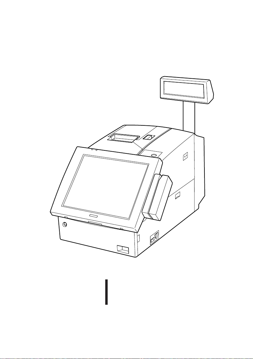
IM-300
Using this online user's guide
The words on the left side of this screen are bookmarks for all
the topics in this manual.
Use the scroll bar next to the bookmarks to find any topic you
want. Click a bookmark to instantly jump to its topic. (If you
wish, you can increase the size of the bookmark area by
dragging the dividing bar to the right.)
Use the zoom tools to magnify or reduce the page display.
Click the Find button if you want to search for a particular
term. (However, using the bookmarks is usually quicker.)
Complete online documentation for Acrobat Reader is located in the Help directory for Acrobat
Reader.
Page 2
IM-300
User's Manual
4008676
01
Page 3

Copyright Information
All rights reserved. No part of this publication may be reproduced, stored in a
retrieval system, or transmitted in any form or by any means, electronic,
mechanical, photocopying, recording, or otherwise, without the prior written
permission of Seiko Epson Corporation. No patent liability is assumed with
respect to the use of the information contained herein. While every
precaution has been taken in the preparation of this book, Seiko Epson
Corporation assumes no responsibility for errors or omissions. Neither is
any liability assumed for damages resulting from the use of the information
contained herein.
Neither Seiko Epson Corporation nor its affiliates shall be liable to the
purchaser of this product or third parties for damages, losses, costs, or
expenses incurred by the purchasers or third parties as a result of accident,
misuse, or abuse of this product or unauthorized modifications, repairs, or
alterations to this product, or (excluding the U.S.) failure to strictly comply
with Seiko Epson Corporation's operating and maintenance instructions.
Seiko Epson Corporation shall not be liable against any damages or problems
arising from the use of any options or any consumable products other than
those designated as Original EPSON Products or EPSON Approved Products
by Seiko Epson Corporation.
EPSON and ESC/POS are registered trademarks of Seiko Epson Corporation.
Intel and Pentium are registered trademarks, and MMX is a trademark of Intel
Corporation.
Award Software International is a registered trademark of Award Software
International Inc.
IBM, PC/AT, and PS/2 are registered trademarks of International Business
Machines Corporation.
Microsoft and Windows are registered trademarks of Microsoft Corporation.
General Notice: Other product and company names used herein are for
identification purposes only and may be trademarks of their respective
companies.
Notice
The contents of this manual are subject to change without notice.
Copyright 1997, 1998 © by Seiko Epson Corporation, Nagano, Japan.
ii
Page 4

FCC CLASS A
FCC COMPLIANCE STATEMENT FOR AMERICAN USERS
This equipment has been tested and found to comply with the limits for a Class A
digital device, pursuant to Part 15 of the FCC Rules. These limits are designed to
provide reasonable protection against harmful interference when the equipment
is operated in a commercial environment.
This equipment generates, uses, and can radiate radio frequency energy and, if
not installed and used in accordance with the instruction manual, may cause
harmful interference to radio communications. Operation of this equipment in a
residential area is likely to cause harmful interference, in which case the user
will be required to correct the interference at his own expense.
WARNING
The connection of a non-shielded interface cable to this product will invalidate the FCC
Verification of this device and may cause interference levels which exceed the limits
established by the FCC for this equipment.
You are cautioned that changes or modifications not expressly approved by the party
responsible for compliance could void your authority to operate the equipment.
FOR CANADIAN USERS
This Class A digital apparatus meets all requirements of the Canadian Interference-Causing Equipment
Regulations.
Cet appareil numérique de la classe A respecte toutes les exigenves du Règlement sur le matériel brouileur
du Canada.
iii
Page 5

Contents
Handling Guidelines
Introduction
Chapter 1 Setup
Precautions on Setting up.................................................................................................. 1-1
Unpacking the IM-300....................................................................................................... 1-2
Setting up the IM-300........................................................................................................ 1-3
Removing a Side Cover/Side Panel/Rear Cover.......................................................... 1-4
Setting the Jumpers and DIP Switches....................................................................... 1-6
Installing a CPU..........................................................................................................1-12
Installing a SIMM.......................................................................................................1-14
Installing a User ROM................................................................................................1-16
Installing a Battery Unit..............................................................................................1-17
Installing a Keyboard Unit...........................................................................................1-19
Installing an LCD Unit................................................................................................1-23
Installing an MSR Unit................................................................................................1-25
Mounting a Printer Tray..............................................................................................1-27
Installing a Printer.......................................................................................................1-29
Installing a DM Display...............................................................................................1-29
Installing an ISA/PCI Board.......................................................................................1-30
Installing a PCMCIA Expansion Module.....................................................................1-32
Installing a Hard Disk Drive........................................................................................1-34
Attaching a Side Cover Panel/Side Panel....................................................................1-37
Installing other Peripherals..........................................................................................1-38
Attaching a Power Cable............................................................................................1-39
Attaching the Rear Cover...........................................................................................1-40
Charging Lithium Batteries.........................................................................................1-42
Chapter 2 Operation
Power ON and Off........................................................................................................... 2-2
Key Lock Keys................................................................................................................. 2-3
Security Key...................................................................................................................... 2-4
iv
Page 6

Inserting and Removing a Floppy Disk.............................................................................. 2-5
Reset................................................................................................................................. 2-6
Paper Feed Button............................................................................................................ 2-7
LCD Contrast Adjustment................................................................................................. 2-7
LCD/Keyboard Angle Adjustment.................................................................................... 2-8
How to Read a Magnetic Stripe Card............................................................................... 2-8
Chapter 3 System Utilities
BIOS Setup Utility............................................................................................................. 3-1
Starting the BIOS Setup.............................................................................................. 3-2
Help Windows............................................................................................................. 3-2
When a Problem Occurs.............................................................................................. 3-2
Legend Keys............................................................................................................... 3-3
Main Menu.................................................................................................................. 3-4
Standard CMOS Setup................................................................................................ 3-5
BIOS Features Setup.................................................................................................. 3-7
Power Management.................................................................................................... 3-8
PnP/PCI Configuration............................................................................................... 3-9
Integrated Peripherals.................................................................................................3-10
Password Setting.........................................................................................................3-12
Device Diagnostics Utility.................................................................................................3-13
Device Diagnostics Utility Requirements....................................................................3-13
Starting Device Diagnostics........................................................................................3-14
Device Diagnostics Utility Screen..............................................................................3-15
Using the Setup Menu.................................................................................................3-21
Drawer On Time.........................................................................................................3-21
Running Device Tests..................................................................................................3-22
Initializing Device Diagnostics.....................................................................................3-25
Exiting Device Diagnostics..........................................................................................3-25
84-Key Configuration Utility..............................................................................................3-26
Start..........................................................................................................................3-26
Speed Buttons.............................................................................................................3-27
Defining Keys.............................................................................................................3-28
v
Page 7

Setting a Key Label.....................................................................................................3-29
Setting Keytop Colors.................................................................................................3-29
Running the Key Program...........................................................................................3-30
Saving the Settings......................................................................................................3-30
Loading the Settings....................................................................................................3-30
New..........................................................................................................................3-31
Viewing Keytops.........................................................................................................3-31
Printing the Settings.....................................................................................................3-31
Exit ..........................................................................................................................3-31
Key Lock Configuration Utility.........................................................................................3-32
Start..........................................................................................................................3-32
Speed Buttons.............................................................................................................3-33
Defining Keys.............................................................................................................3-34
Setting a Key Label.....................................................................................................3-34
Running the Key Program...........................................................................................3-35
Saving the Settings......................................................................................................3-35
Loading the Settings....................................................................................................3-36
New..........................................................................................................................3-36
Exit ..........................................................................................................................3-36
POS Key Mode Setting Utility...........................................................................................3-37
Start..........................................................................................................................3-37
Commands..................................................................................................................3-37
Messages....................................................................................................................3-39
Key Definition Utility (For MS-DOS)................................................................................3-40
Start..........................................................................................................................3-41
File Command.............................................................................................................3-42
Load Command...........................................................................................................3-43
Save Command...........................................................................................................3-43
Edit Command.............................................................................................................3-44
Download Command...................................................................................................3-46
Quit Command............................................................................................................3-46
Key Table...................................................................................................................3-47
Key Data File..............................................................................................................3-48
Error Messages...........................................................................................................3-49
vi
Page 8

Chapter 4 Troubleshooting
Messages .......................................................................................................................... 4-1
Troubleshooting................................................................................................................. 4-4
The IM-300 Will Not Start .......................................................................................... 4-5
The IM-300 Always Stops at Bootup .......................................................................... 4-6
The IM-300 Does Not Respond .................................................................................. 4-6
The IM-300 Shuts Down............................................................................................. 4-6
The IM-300 Can't Be Turned Off ............................................................................... 4-6
Keyboard Problems..................................................................................................... 4-7
Monitor Problems........................................................................................................ 4-7
EPSON DM-D Display Problems............................................................................... 4-8
Floppy Disk Problems ................................................................................................. 4-8
Hard Disk Problems.................................................................................................... 4-9
TM Printer Problems .................................................................................................. 4-9
Serial Port Problems ................................................................................................... 4-10
Parallel Port Problems................................................................................................. 4-10
Cash Drawer Problems............................................................................................... 4-10
PC Card Problems ...................................................................................................... 4-11
Appendix A Specifications
CPU and Memory ............................................................................................................. A-1
Controllers......................................................................................................................... A-2
Interfaces .......................................................................................................................... A-2
Expansion Slots.................................................................................................................. A-3
Disk Drives ....................................................................................................................... A-3
Security ............................................................................................................................. A-4
Switches............................................................................................................................ A-4
Indicators........................................................................................................................... A-5
System Utilities.................................................................................................................. A-5
Power................................................................................................................................ A-5
Power Limits ..................................................................................................................... A-7
vii
Page 9

Lithium Batteries...............................................................................................................A-7
Dimensions........................................................................................................................A-8
Environmental Requirements.............................................................................................A-9
DMA Assignments............................................................................................................A-10
Hardware Interrupts...........................................................................................................A-11
System Memory Map........................................................................................................A-12
I/O Addresses....................................................................................................................A-13
Connector Pin Assignments................................................................................................A-14
Appendix B Loop-Back Connector
Appendix C Memory Specifications
SIMM Specifications.........................................................................................................C-1
User ROM Specifications....................................................................................................C-2
viii
Page 10

Introduction
The IM-300 is an intelligent terminal developed for the POS environment.
The IM-300 has the following features.
1.An Intel Pentium processor or Intel MMX technology Pentium
processor can be used. This high speed CPU processor provides the
power and speed necessary for data processing.
2.Using it in combination with a variety of options and peripheral devices
allows you to construct a system that suits your needs best.
3.The security on the front panel allows only the key owner to take out the
floppy disk and the hard disk drive.
4.The keylock keys allow setting of the user's authority.
5.The refined power management function supplies power by the amount
necessary for data processing, assuring optimum power saving.
6.Use of an updatable 256KB flash ROM for system ROM.
7.Use of PC/AT compatible BIOS. This allows you to execute not only
specific application software but also any PC program of your choice.
8.Use of a built-in Device Diagnostics utility allows quick and easy error
handling.
9.Support of Plug & Play function
10. Capability of supplying +5V or +12V to all serial ports.
11. Equipped with 32KB NVRAM for POS
12. Uses a PC-based open architecture to increase system expandability,
providing one ISA slot, one PCI/ISA slot, and one special extension slot.
13. Input/output units include the keyboard unit, which allows free definition
of key functions and the LCD unit. A touch-panel type of LCD unit is also
available, which allows you to do the free layout of the screen.
14. The built-in IBM PS/2 keyboard port supports IBM PC/AT compatible
keyboards.Therefore, it is possible to connect any commercially
available keyboard in accordance with your environment.
15. Use of standard SIMMs allows you to install memory of up to 64MB.
16. Four serial ports and one parallel port allow connection of industry standard peripheral devices, increasing system expandability.
17. In addition to the standard 3.5-inch floppy disk drive, up to two 2.5-inch
hard disk drives can be installed.
Introduction 1
Page 11

18. The hard disk drive can easily be removed or mounted. In the event of a
system failure, the hard disk can be moved immediately to another IM 300 to continue the processing.
19. Use of design consistent with EPSON POS system TM series printers. A
TM printer can be mounted on the IM-300, so it does not occupy much
space.
20. Connection of the dedicated MSR (magnetic stripe reader) unit (option)
makes it possible to read magnetic cards.
21. Mounting of a battery unit (option) provides data backup function (Save
To Disk Function) when the power is off accidentally.
22. Capability to mount user ROMs of up to 2MB.
2 Introduction
Page 12
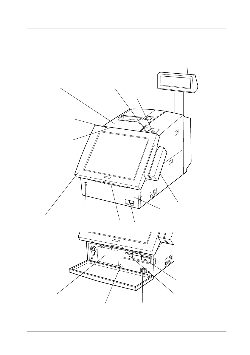
Part Names
Illustrations below show the part names of this product.
Customer Display (Option)
Printer Unit (Option)
Power Indicator
HDD Indicator
LCD unit (Option)
Paper Feed Switch
Front Cover Lock
Lock Switch
Keylock
MSR Unit (Option)
Front Cover
Front Power Switch
HDD slot
Reset Switch
Eject Button
FDD Indicator
Front Power Switch
Front View
Introduction 3
Page 13
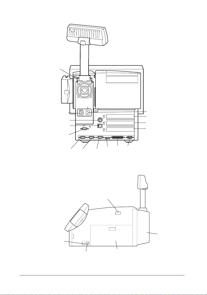
DM-D (at the base of the
customer display)
AC Outlet
TM Power Supply Connector
DKD Connector
COM4
COM3 COM2 COM1
USB2 Connector
Keyboard/Mouse Connector
LPT CRT
USB1
Rear View
Side Power Switch
Side View
AC Inlet
Exclusive Slot
ISA Slot
PCI/ISA Slot
Rear Cover
Side Cover
4 Introduction
Page 14
Handling Guidelines
Warnings, Cautions, and Notes
Notes and precautions in this manual are identified by their level of
importance, as defined below.
WARNING
Provides information that must be observed to prevent harm (not lifethreatening) to the user.
Caution
Provides information that must be observed to prevent damage to the
equipment or loss of data.
Note:
Provides important information and useful tips on handling the equipment.
Handling Precautions 1
Page 15

WARNING
• Turn off the side power switch immediately if it produces smoke, a
strange odor, or unusual noise. Continued use may lead to fire or electric
shock.
Immediately unplug the power cord and contact your dealer or a SEIKO EPSON
service center for advice.
•Never attempt to repair this product yourself. Improper repair work can
be dangerous.
•Never disassemble or modify this product.
Tampering with this product may result in injury, fire, or electric shock.
• Never insert or disconnect the power plug with wet hands.
Doing so may result in severe shock.
• Do not allow foreign objects to fall into this product.
Penetration by foreign objects may lead to fire or shock.
• If water or other liquid spills into the this product, turn off the side power
switch, unplug the power cord immediately, and then contact your dealer
or a SEIKO EPSON service center for advice.
Continued usage may lead to fire or shock.
• Do not place multiple loads on the power outlet (wall outlet).
Overloading the outlet may lead to fire.
• Always supply power directly from a standard domestic power outlet.
• Handle the power cable with care.
• Do not attempt to open or disassemble the internal Vanadium-Lithium
battery, which could result in burns or release of hazardous chemicals.
• Do not charge or leave the internal Vanadium-Lithium battery in a hot
place, such as near a fire or on a heater, as it could overheat and ignite.
• When you dispose of the internal Vanadium-Lithium battery, insulate it
by wrapping the terminals with a tape.
Mixing the battery with other metals or batteries may lead to fire, heat, or
explosion.
2 Handling Precautions
Page 16

Caution
• Be sure your power cable meets the relevant safety standards and includes
a power-system ground terminal (PE terminal).
• Be sure to set this equipment on a firm, stable, horizontal surface.
The product may break or cause injury if it falls.
• Do not use in locations subject to high humidity or dust levels.
Excessive humidity and dust may cause equipment damage, fire, or shock.
• Do not place heavy objects on top of this product.
Equipment may fall or collapse, causing breakage and possible injury.
• To ensure safety, please unplug this product prior to leaving it unused for
an extended period.
• Do not drop, bump or otherwise subject this product to strong vibration or
impact.
• Be sure to attach the rear cover after setup.
If the rear cover isn't attached, some foreign matter may enter this product causing
trouble.
• Be sure to attach the side covers and the side panels after setup.
Handling Precautions 3
Page 17

4 Handling Precautions
Page 18

Chapter 1
Setup
This chapter explains how to set up your hardware. For configuring your
system using the BIOS Setup, see the next chapter.
Precautions on Setting up
This section describes items to observe when setting up the IM-300.
In addition to the above, there are warning instructions and cautions to
observe at each work stage. They are given in each explanation.
Caution
• Turn off the power of all equipment including the IM-300 and all the
peripherals before setup. Be sure to turn off the side power switch for
the IM-300 to turn it off.
When power is on, the IM-300 or peripherals units may be
damaged during setup.
• Before setup, discharge static electricity on your body.
If you do not allow static electricity to discharge, trouble could
result. Touch a grounded metal surface to allow static electricity
to discharge.
• Do not touch the connectors.
Dirt may cause a malfunction.
Setup 1-1
Page 19
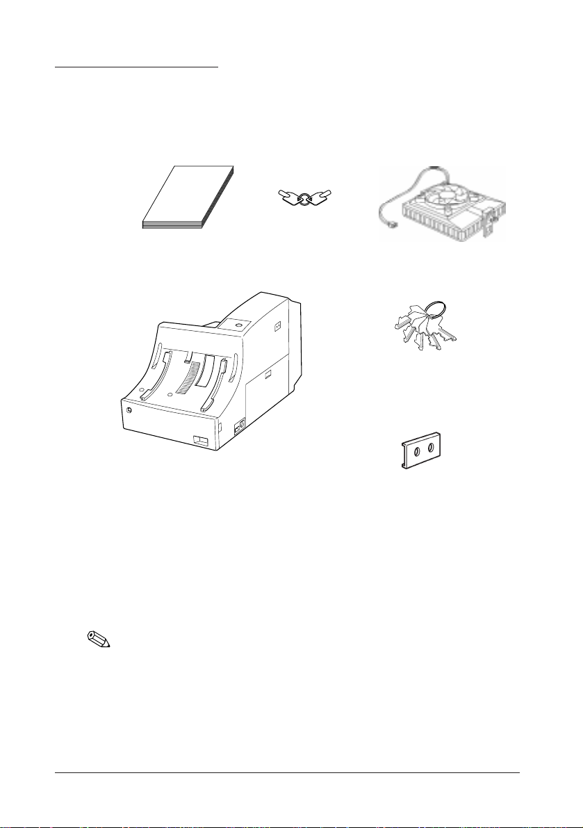
Unpacking the IM-300
When you unpack the IM-300, make sure you have these itmes:
User's manual
IM-300
Front keys
(2 pieces)
CPU cooling fan
Keylock keys
(5 pieces)
Switch covers (2)
Screws to fix the HDD (4)
Confirm that the package includes the items above. If any of these items are
damaged or missing, please contact your dealer for assistance.
1-2 Setup
Note:
After unpacking, save the packaging materials so that you can reuse them, if
necessary
.
Page 20

Setting Up the IM-300
Set up the IM-300 in the following steps. If you don't use the specified
options, skip that step.
Step Page
Removing a Side Cover/Side Panel/Rear Cover 1-4
Setting the Jumpers 1-6
Installing a CPU 1-12
Installing SIMMs 1-14
Installing User ROMs 1-16
Installing a Battery Unit 1-17
Installing a Keyboard Unit 1-19
Installing an LCD Unit 1-23
Installing an MSR Unit 1-25
Mounting a Printer Tray 1-27
Installing a Printer 1-29
Installing a DM Display 1-29
Installing an ISA/PCI Board 1-30
Installing a PCMCIA Expansion Module 1-32
Installing an HDD 1-34
Attaching a Side Cover/Side Panel 1-37
Installing Peripherals 1-38
Attaching a Power Cable 1-39
Attaching a Rear Cover 1-40
Charging Lithium Batteries 1-41
Setup 1-3
Page 21
Removing a Side Cover/Side Panel/Rear Cover
Remove the side covers and the side panels on both sides of the IM-300.
Remove the side covers and the side panels in the following cases:
Right Side (on which the side power switch is located)
Setting the jumpers and DIP switches
(For CPU speed setting, CPU voltage, pin 1 function of
COM1 to COM4 and COM3 function)
Installing a CPU, installing SIMMs
Left Side
Setting the jumpers
(For gate array mode and CMOS RAM clear)
Installing user ROMs
Installing ISA/PCI cards
Installing a PCMCIA expansion module
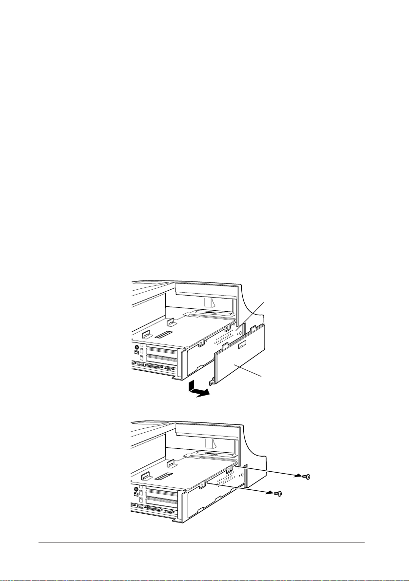
Remove the side covers and side panels using the following procedure:
1. Remove the side cover by sliding downward.
Side Panel
2. Remove two screws, which fix the side panel.
3. Remove the side panel.
1-4 Setup
Side Cover (Left)
Page 22
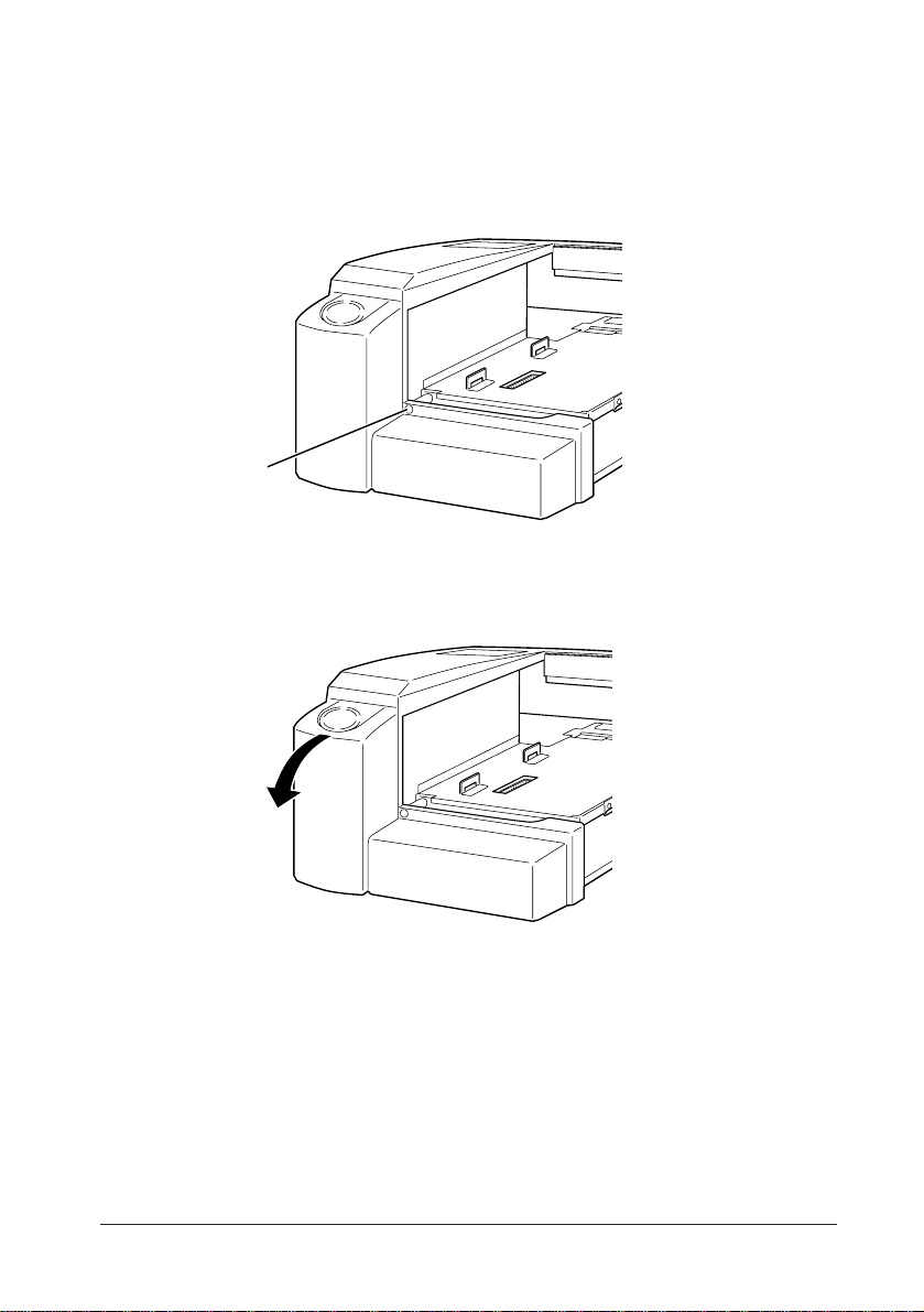
If a rear cover is attached to the IM-300, remove it using the following
procedure.
1. Loosen a screw that fastens the rear cover.
screw
2. Remove the rear cover from the IM-300 by pulling the upper part of the
rear cover backward then downward.
Setup 1-5
Page 23
Setting Jumpers and DIP Switches
There are jumpers and DIP switches on the board of the IM-300. You can
set them to control how the system operates.
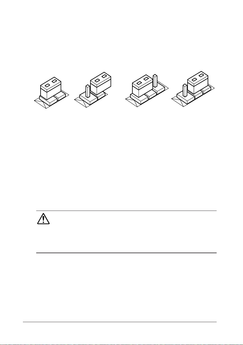
There are two types of jumpers - the 2-pin jumper and 3-pin jumper.
3
On
2-pin jumper 3-pin jumper
Off
1
1-2
1
For two-pin jumpers, the jumper is either on (it connects the two pins) or off
(it doesn't connect the two pins).
For three-pin jumpers, the jumper setting is 1-2 when the jumper connects
pins 1 and 2. The setting is 2-3 when pins 2 and 3 are connected. You see a
1 and a 3 printed on the circuit board to identify these pins. Also, one of the
lines surrounding jumpers is thick, which indicates pin NO.1.
To move a jumper from one position to another, use needle-nose pliers or
tweezers to pull it off the pins and move it to the desired position.
Caution
• Be careful not to bend the jumper pins or damage any components on the board.
• Do not change settings for jumpers and DIP switches not covered in this
manual.
3
2-3
1-6 Setup
Page 24
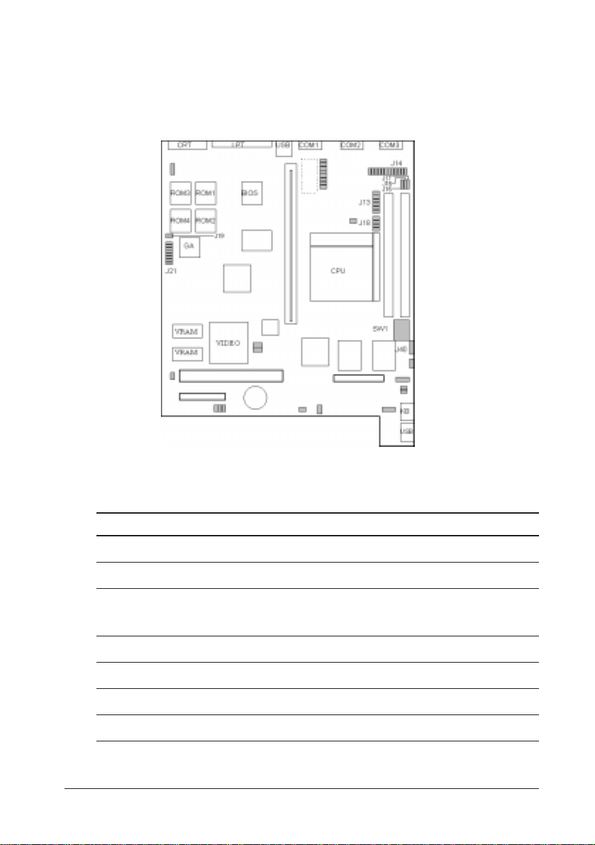
Jumpers and DIP Switches Locations
The figure below shows the locations of jumpers and the DIP switches on
the IM-300 main board.
Use the information in the following table to change the jumpers and the DIP
switches.
Jumpers/DIP Switches Functions
SW1, J40 Selection of CPU operation speed
J13 Selection of CPU power voltage
J14 Serial port pin 1 assignment
(DCD, +5V, +12 select)
J18 Selection of CPU power voltage
J21 Selection of gate array operation mode
J15, J16, J17 Selection of COM3
J19 CMOS RAM clear
Setup 1-7
Page 25

Settings of SW1 and J40:
These DIP switches determine the CPU operation speed. Change the DIP
switch settings for the installed CPU.
Selection of CPU operation speed
CPU Frequency J40SW1SW1SW1SW1
1-2 1-3 1-4 1-5
Pentium 90 MHz 1-2 OFFOFFON ON
Pentium 100 MHz 1-2 OFFOFFOFFON
Pentium 120 MHz 2-3 OFFOFFONON
Pentium (*) 133 MHz 2-3 OFFOFFOFFON
Pentium 150 MHz 2-3 ON OFFONON
Pentium 166 MHz 2-3 ON OFFOFFON
Pentium 200 MHz 1-2 ON OFFOFFON
Pentium MMX166 MHz 2-3 ON OFFOFFON
Pentium MMX200 MHz 1-2 ON OFFOFFON
* Default settings
1-8 Setup
Page 26

Settings of J13/J18:
These jumpers determine the CPU power voltage. Change the jumper
settings for the installed CPU.
Selection of CPU power voltage
CPU Frequency J13 J13 J13 J13 J18 J18 J18 J18
1-2 3-4 5-6 7-8 1-2 3-4 5-6 7-8
Pentium 90 MHz ON OFF ON ON OFF OFF ON ON
Pentium 100 MHz ON OFF ON ON OFF OFF ON ON
Pentium 120 MHz ON OFF ON O N OFF OFF ON ON
Pentium (*) 133 MHz ON OFF ON ON OFF OFF ON ON
Pentium 150 MHz ON OFF ON O N OFF OFF ON ON
Pentium 166 MHz ON OFF ON O N OFF OFF ON ON
Pentium 200 MHz ON OFF ON O N OFF OFF ON ON
Pentium MMX 166 MHz ON OFF OFF OFF ON ON OFF OFF
Pentium MMX 200 MHz ON OFF OFF OFF ON ON OFF OFF
* Default settings
Setup 1-9
Page 27

Settings of J14:
This jumper determines the pin 1 function of COM1 to COM4 serial port.
Selection of the serial port pin 1 assignment
COM1 COM2 Pin 1 Function
1-2 3-4 5-6 7-8 9-10 11-12
ON OFF OFF ON OFF OFF DCD (*)
OFF ON OFF OFF ON OFF +5V
OFF OFF ON OFF OF F O N +12V
COM3 COM4 Pin 1 function
13-14 15-16 17-18 19-20 21-22 23-24
ON OFF OFF ON OFF OFF DCD (*)
OFF ON OFF OFF ON OFF +5V
OFF OFF ON OFF OF F O N +12V
* Default settings
Settings of J21:
This jumper sets gate array operations, such as user ROM control, use of
NVRAM for POS, and so on.
Settings of Gate Array
Switch Function Setting Description
1 to 6 User ROM control Refer to next table
7-8 (SW4) Use of NVRAM for POS OFF (*) Not used.
ON Used.
9-10 (SW5) Use of user ROM for POS OFF (*) Not used.
ON Used.
11-12 (SW6) Selection of gate array mode OFF Reserved.
ON (*) Fixed to ON.
* Default settings
1-10 Setup
Page 28

User ROM Control Settings
SW1 (1-2) SW2 (3-4) SW3 (5-6) Description
ON(*) ON(*) ON(*) Normal ROM mode
ON OFF O N Extended ROM mode, starting address D0000h
ON OFF O FF Extended ROM mode, starting address D8000h
OFF - - Bootstrap ROM mode (BIOS ROM mode)
- Do not care
* Default settings
Settings of J15, J16 and J17:
Jumper Function Settings Description
J15 COM3 RXD 1-2 Use RXD of the external COM3
connector on the motherboard
2-3 Use RXD of the internal connectors (*)
J16 COM3 DSR Selection 1-2 Use DSR of the external COM3
connector on the motherboard
2-3 Use DSR of the internal connectors (*)
J17 COM3 CTS Selection 1-2 Use CTS of the external COM3 connector
on the motherboard
2-3 Use DSR of the internal connectors (*)
* Default settings
Settings of J19:
Jumper Function Settings Description
J19 CMOS Clear OFF (*) CMOS RAM data remains.
ON Clears CMOS RAM data.
* Default settings
Setup 1-11
Page 29

Installing a CPU
IM-300 contains a Socket 7, which can accept the following CPU types:.
• Intel Pentium 100 MHz to 200 MHz
• Intel MMX technology Pentium 166/200 MHz
Be sure to attach a CPU cooling fan to the CPU included in the package
after you install the CPU. It prevents the CPU from overheating.
Caution
• To avoid generating static electricity and damaging the CPU, ground yourself by
touching a grounded metal surface before you touch the CPU.
• Do not remove the rubber under the CPU cooling fan.
• Do not touch the pins of the CPU.
Dirt may cause a malfunction.
Follow these steps to install the CPU:
1. Confirm that the DIP switches are correctly set for the CPU you are going
to install.
2. Lift the release lever of the Socket 7.
3. Align the pins of the CPU to the pin holes of the Socket 7. Be sure to pay
attention to the direction of the CPU.
lever
4. Push down the CPU into the Socket 7.
5. Push down the release lever and lock it.
1-12 Setup
Page 30
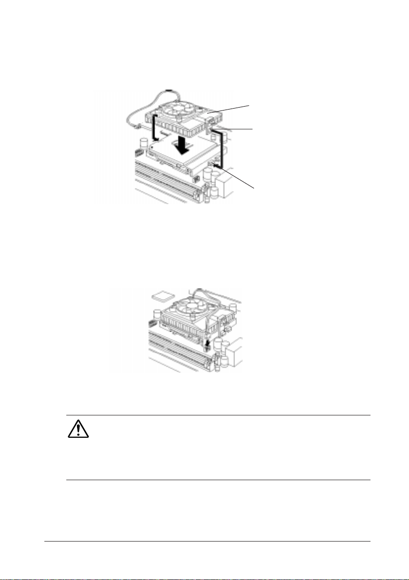
6.Hook the hole in EIF clip for the CPU cooling fan onto the notch on the
Socket 7.
7.Place the CPU cooling fan on the CPU surface.
Heat radiation plate
EIF clip
Notch
8.Push down the opposite side of the EIF clip and hook it.
9.Slide the head of the clip to left and lock it.
10. Connect the cooling fan cable to the socket as shown below. Be careful
not to place the cable on the CPU cooling fan.
Removing a CPU:
Caution
Before removing the CPU, turn off the IM-300 power; then wait for about 20 minutes until
the heat radiation plate of the cooling fan and the CPU cool down.
The CPU and the heat radiation plate are hot. They may cause burns.
To remove the CPU, reverse the installation steps.
Setup 1-13
Page 31

Installing a SIMM
The main board contains two SIMM sockets. You can insert one SIMM or
two SIMMs. However, it is recommended that you use two SIMMs of the
same type and access speed.
The SIMMs must meet the specifications in Appendix C.
Caution
• To avoid generating static electricity and damaging the SIMM, ground
yourself by touching a grounded metal surface before you touch the SIMM.
•Do not touch the connector of the SIMM.
Dirt may cause a malfunction.
Follow these steps to install the SIMMs:
1.Hold the SIMM with its notch to the front side of the IM-300 and insert
it completely into the socket at an angle of about 45 degrees. A SIMM
should be inserted into the inner socket first.
2.Tilt the SIMM until it is upright, guiding the hole at each end of the
SIMM over the retaining post at each end of the SIMM socket.
1-14 Setup
Page 32

Note:
If SIMM does not go in smoothly, do not force it. Pull it all the way out and try
again.
Caution
Make sure the SIMM is properly installed and locked by the tabs on both sides of
the socket.
3.If you install two SIMMs, install the second SIMM using the same
procedure as above.
Removing a SIMM:
To remove the SIMM, use your fingers or a small screwdriver to carefully
pull away the metal tabs that secure the SIMM at each end. The SIMM falls
to the side. Lift it out of the socket.
Make sure you store the SIMM in an anti-static bag.
Setup 1-15
Page 33

Installing a User ROM
On the IM-300, up to four user ROMs storing independent user programs
can be installed. Using the special driver, they can be used as virtual
memories with a capacity of 2MB max.
The user ROMs must meet the specifications in Appendix C.
User ROMs should be installed in the sockets in order as shown below.
(1)
(3)
(2)
(4)
Caution
• To avoid generating static electricity and damaging the ROM, ground yourself by
touching a grounded metal surface before you touch the user ROM.
• Do not touch the connectors of the user ROM.
Dirt may cause a malfunction.
Follow these steps to install the user ROM:
1. Confirm that the jumpers are correctly set for the user ROMs you are going
to install.
2. Confirm the direction of the user ROM. A mark on the user ROM should be
located as shown below.
3. Push down the user ROM into the socket.
1-16 Setup
Page 34

Installing a Battery Unit
The battery unit is the Ni-Cd battery that backs up operations during data
saves to the hard disk drive by the STD (Suspend To Disk) function, which
happens automatically if the power turns off abruptly, such as in case of a
power interruption.
The specifications for the battery unit are as follows:
Type: Ni-Cd 8-cell, 600 mAh
Charging time: About 32 hours
Charging method: Trickle
The charging time and backup time change according to the environmental
conditions.
Note: (Users in the USA)
The product you have purchased is powered by a nickel cadmium battery
which is recyclable. At the end of its useful life, under various state and local
laws, it is illegal to dispose of this battery into your municipal waste stream.
Please call 1-800-8-BATTERY for information on how to recycle this battery.
Note:
The nickel cadmium battery must be recycled or disposed of properly.
The battery unit begins to be charged when the IM-300 power is turned on.
Install the battery unit by following the procedure below.
1. Open the battery unit box.
Setup 1-17
Page 35

2. Insert a battery unit into the battery unit box.
3. Close the battery unit box.
4. Connect the cable of the battery unit as shown below.
Note:
To enable the battery unit, change the "System Battery" setting in the Power
Management menu of the BIOS setup to "Equipped." See to Chapter 4 for
details.
Removing a Battery Unit:
To remove the battery unit, reverse the installation steps.
1-18 Setup
Page 36

Installing a Keyboard Unit
The keyboard unit is an option for data entry. It has a total of 84 keys, in 12
rows by 7 columns. A function can be freely assigned to each key. By
assigning the same function to two or more keys, you can also handle the
multiple keys as one large key. For this purpose, the keyboard unit box also
contains keytops measuring 1 by 2 and 2 by 2.
The slide mechanism allows the keyboard surface inclination to slide
vertically for setting the optimum angle.
Follow these steps to install a keyboard unit:
1. Check that the lock switch in the lower part of the keyboard unit is set in the
release position.
2. Place the keyboard unit on the IM-300 and slide it downward. At this time,
the keyboard unit and IM-300 should be aligned with each other.
3. Incline the keyboard unit to the desired angle.
4. Set the keyboard unit lock switch to the lock position, and secure the
keyboard.
Setup 1-19
Page 37

5. Connect the cable of the keyboard unit as shown below. At this time, do not
bend the connector pins.
Changing a Keytop:
To change a keytop on the keyboard unit, follow the procedure below.
1. Fit the keytop remover (contained in the keyboard unit package) over the
desired keytop, as shown below.
2. Lift the keytop remover to detach the keytop.
3. To detach more than one keytop, repeat steps 1 and 2.
4. Fit the new keytop straight from above.
1-20 Setup
Page 38

Mounting a Keytop Cover:
The keyboard unit package also contains keytop covers. A keytop is indented
on top. Mount the keytop cover over the indent. Then, you can see the function
of the key with ease.
Place the keytop cover in position with the procedure below.
1. Insert a label for the key function on the keytop.
2. Fit the keytop cover, with its concave side up, over the keytop. Then, fit the
cover securely, until you hear a snap.
Removing a Keytop Cover:
To remove the keytop cover, follow the procedure below.
1. Remove the keytop using the keytop remover.
2. Remove the keytop, turn it over, and push the keytop cover out with a
pointed object such as a pin.
Setup 1-21
Page 39

Removing a Keyboard Unit:
To remove the keyboard unit, follow the procedure below.
1. Detach the keyboard unit cable from the connector.
Caution
Be careful not to injure yourself on the edges of the case when you detach the
keyboard unit cable.
2. Slide the lock switch of the keyboard unit to the release position.
3. As shown below, slide the lock of the keyboard unit while pulling it up with
your fingers and lift it up as shown.
1-22 Setup
Page 40

Installing an LCD Unit
There are two types of LCD unit: with touch panel or without touch panel.
The specifications for the LCD unit are as follows:
LCD panel: 10.4-inches, color DSTN type
640 x 480, 256 colors
Back light life: 25,000 hours until brightness is reduced
to half.
Touch panel: Resistor film type
Serial communication COM4, 9600 bps
(Touch panel)
A slide mechanism lets the LCD surface inclination slide vertically for
setting the optimum angle.
Follow these steps to install an LCD unit:
1. Check that the lock switch in the lower part of the LCD unit is set in the
release position.
2. Set the LCD unit on the IM-300 and slide it downward. At this time, the
LCD unit and IM-300 should be aligned with each other, as shown below.
3. Incline the LCD unit to the desired angle.
4. Set the LCD unit lock switch to the lock position, and secure the LCD.
Setup 1-23
Page 41

5. Connect the two cables for the LCD unit to the connectors. At this time, do
not bend the connector pins.
Removing an LCD Unit:
To remove the LCD unit, follow the procedure below.
1. Detach the LCD unit cables from the connector.
Caution
Be careful not to injure yourself on the edges of the case when you detach the
LCD unit cable.
2. Slide the lock switch of the LCD unit to the release position.
3. As shown below, slide the lock of the LCD unit while pulling it up with your
fingers and lift it up as shown.
1-24 Setup
Page 42

Installing an MSR Unit
The LCD unit and keyboard unit are equipped with an interface for a
connection to a magnetic stripe reader (MSR).
Two types of MSR units can be connected to the IM-300. They differ in
specification of readable magnetic card.
Model Name Specification of readable magnetic card
DM-MR111-012 ISO conforming to JIS1, track 1+2
DM-MR111-013 ISO conforming to JIS1, track 2+3
Mount the MSR unit by following the procedure described below.
1. Open the connector cover on the right side of the LCD unit or keyboard
unit.
2. Connect the MSR unit to the MSR interface.
Setup 1-25
Page 43

3. Secure the MSR unit using the two screws in the package for the MSR unit.
Removing an MSR Unit:
To remove the MSR unit, reverse the installation steps.
Note:
When you remove the screws and then want to fix them again, first turn them
counterclockwise slightly, and then fix them.
1-26 Setup
Page 44

Mounting a Printer Tray
When using the IM-300 either with or without an EPSON TM printer, mount
the printer tray as a top cover for the IM-300. The TM printer can be set on the
printer tray.
Mount the printer tray by following the procedure below. If you are not using
a TM printer, begin with step 3.
1. Separate the hatched part of the printer tray from the rest of the printer tray.
Then cut off the two plastic connecting pieces (burrs) with a cutter and pull
the piece down toward you. Bend the part back and forth two or three
times, so that you can cut the part off. You can now pass the cable through
the new opening.
Caution
•If burrs are left after the hatched part is removed, you may cut or scratch your fingers, etc.
Remove the burrs left on the printer tray with a cutter or file them down.
2. When setting up the TM printer on the printer tray, wrap the cable around
the poles on the other side of the tray, as shown below, to keep it out of the
way.
Setup 1-27
Page 45

3. Slide the printer tray in the direction of the arrow and fit the hooks on the
printer tray into the slots in the IM-300 base unit.
4. Secure the printer tray with two screws.
5. To set up the TM printer, it should be inserted on the printer tray.
Removing a Printer Tray:
To remove the printer tray, reverse the installation steps.
1-28 Setup
Page 46

Installing a Printer
EPSON TM series printers and the printer unit for the IM-300 can be
connected to the IM-300. For how to connect the printer unit, please refer to
the printer unit installation manual.
The IM-300 assigns the COM3 serial port to printer by default. So, connect
the serial communication cable to the COM3 port of the IM-300 and change
jumpers J15 through J17 to 1-2 (to use the external COM3). Also, if you want
to get printer power from the IM-300, connect the printer power cable (After
service part: DC cable set: 201809900) to TM power supply on the IM-300.
TM power supply
COM3
Caution
• Never connect a printer to the TM printer power supply port that is not listed below:
* TM-U200 series * TM-T85 series *TM-U300 series
* TM-U210 series * TM-U325 series
• If you connect one of the printer models especially designed for the IM-300 (such as TM-
T88R or TM-U210R), never attach the printer to the TM power supply.
Refer to the respective printer manual for the installation procedure.
Installing a DM Display
The EPSON DM-D102 customer display can be connected to the IM-300.
The DM-D102 customer display uses the COM3 serial port by default.
Be sure to connect the DM display cable to the DM display port on the IM-
300. See the DM display manual for installation procedure details.
Setup 1-29
Page 47

DM display connector
Exclusive slot
ISA slot
PCI / IASA slot
USB1
COM3
COM4
TM P/S
COM1 CRTLPT
COM2
DKD
Caution
Never plug a telephone line into the DM display port.
Installing an ISA/PCI Board
The IM-300 has one ISA expansion slot and one ISA/PCI expansion slot. You
can insert one ISA board into the ISA expansion slot, and either one ISA or
one PCI board into the ISA/PCI expansion slot.
ISA
PCI/ISA
The mamimum size of the ISA/PCI boards are as follows:
Length Width Height Height
(Parts side) (Solder side)
195 mm (7.7") 107 mm (4.2") 12 mm (0.5") 10 mm (0.4")
1-30 Setup
Page 48

Install the ISA/PCI board by following the procedure below.
1. Remove the retaining screw securing the slot cover. Keep the screw to
secure the ISA/PCI board.
2. Slide the slot cover out and set it aside. Store the slot cover in case you
remove the ISA/PCI board later.
3. Gently guide the board into the connector.
Push the board in firmly (but carefully) to insert it fully. You should feel
the connectors fit into place. If the board does not go in smoothly, do not
force it; pull it all the way out and try again.
4. Secure the end of the ISA/PCI board to the IM-300 with the retaining
screw.
Removing an ISA/PCI Board:
To remove the ISA/PCI board, remove the retaining screw securing the board.
Pull the board straight out of the slot, then replace the slot cover.
After removing the ISA/PCI board, attach a slot cover.
Setup 1-31
Page 49

Installing a PCMCIA Expansion Module
You can install an optional PCMCIA expansion module (OI-B06) in the
exclusive slot (top slot). The PCMCIA expansion module can support two
Type I or Type II cards or a single Type III card.
Exclusive slot
Install the PCMCIA expansion module using the procedure below.
1. Remove the retaining screw securing the cover for the exclusive slot to the
IM-300, as shown below. Keep the screw to secure the PCMCIA
expansion module to the IM-300.
2. Slide the slot cover out and set it aside. Store the slot cover in case you
remove the PCMCIA expansion module later.
1-32 Setup
Page 50

3. Push both sides of the PCMCIA slot cover inward and remove it from the
PCMCIA expansion module.
PCMCIA slot cover
4. Gently guide the PCMCIA expansion module into the top connector.
Push the module in firmly (but carefully) to insert it fully. You should
feel the connectors fit into place. If the module does not go in smoothly,
do not force it; pull it all the way out and try again.
Note:
Remove the PCMCIA slot cover before you install or remove the PC cards.
Removing a PCMCIA Expansion Module:
To remove the PCMCIA expansion module, reverse the installation steps.
Setup 1-33
Page 51

Installing a Hard Disk Drive
You can install a 2.5 inch hard disk drive (0.74 inch high maximum) in the
IM-300. A mounting bracket and an adapter board must be attached to the
hard disk drive.
Caution
Handle the hard disk drive gently. Do not bump or drop the hard disk drive.
Small shocks or vibrations could damage the drive.
Follow these steps to install the hard disk drive.
1. Open the front panel of the IM-300. If the front panel is locked, unlock it
with the front key. To unlock the front panel, insert the front key into the
front keylock and turn it down pushing slightly.
Front cover
Front key
2. Open the HDD cover. Open it while lightly pushing down the two tabs.
HDD cover
1-34 Setup
Page 52

3. Loosen the screw fixing the HDD mounting bracket.
4. Pull out the HDD mounting bracket as shown below.
HDD mounting bracket
5. Attach the hard disk drive onto it, by sliding the hard disk drive as shown
below and fixing it with four screws.
Caution
The tighting torque for all four screws must not exceed 29.4cN·m{3kgf·cm}.
If the tighting torque exceeds this value, some problems may occur.
6. Slide the HDD mounting bracket into the slot so that the notches along the
bottom are under the tabs of the hard disk slot.
7. Push the HDD mounting bracket in gently until you feel the connector fit
into place.
8. Attach the HDD mounting bracket to the IM-300 with a screw.
9. Close HDD cover.
10. Close the front panel.
Setup 1-35
Page 53

Removing a Hard Disk Drive:
To remove the hard disk drive, reverse the installation steps.
1-36 Setup
Page 54

Attaching Side Covers/Side Panels
Caution
• Be sure to attach the side covers and the side panels after setup.
Follow these steps to attach the side panels and the side covers:
1. Attach the side panel and secure it with two screws. Each side panel has
different positions for the screws.
2. Attach the side covers.
Setup 1-37
Page 55

Installing Other Peripherals
The following options can be attached to the IM-300. Refer to the manual for
each peripheral for the installation procedure.
• Mouse (connected to the keyboard/mouse connector through a branch cable)
• Keyboard (connected to the keyboard/mouse connector)
Keyboard/mouse connector
Note:
• To connect a mouse, a commercially available branch cable is required. Attach
the branch cable to the keyboard/mouse connector and connect the mouse to the
cable.
•With some cables, you need to attach the mouse to the keyboard connector and
the keyboard to the mouse connector.
• Cash drawer (connected to the DKD connector)
DKD connector
Caution
• Never plug a telephone line into the DKD connector.
• When the TM power supply is used, the DKD connector can't be used.
1-38 Setup
Page 56

Attaching a Power Cable
The power cable is an option. Select a power cable that meets the
specifications below.
Input voltage (rating) 90 (100-10%) VAC to
264 (240+10%) VAC
Frequency (rating) 50/60 Hz + 2 Hz
Input power (rating) 180 VA or less
Caution
• Never insert or disconnect the power plug with wet hands.
Doing so may result in severe shock.
• Do not place multiple loads on the power outlet (wall outlet).
Overloading the outlet may lead to fire. Always supply power directly from a power
outlet.
Follow these steps to attach the power cable:
1. Connect the power cable to the IM-300.
2. Connect the power plug to the power outlet.
Setup 1-39
Page 57

Attaching the Rear Cover
The IM-300 comes with a rear cover that provides a protective covering for
your cables. After you have connected all the peripherals to the IM-300, attach
the rear cover.
Caution
• Be sure to attach the rear cover after setup.
If the rear cover isn't attached, foreign objects may enter this product causing problems.
Follow these steps to attach the rear cover.
1. Attach the DM display cover.
If the DM display is installed on the IM-300, cut off the portion of the
DM display cover shown below. Cut off the three connecting pieces with
a cutter.
Cut off this
2. Attach the rear cover as shown below.
1-40 Setup
Page 58

3. Secure the rear cover with a screw.
screw
Charging Lithium Batteries
This product contains rechargeable lithium batteries that back up the realtime clock, the CMOS RAM data, and the NVRAM data. The lithium
batteries are not charged fully at the factory. You need to charge the batteries
before you use this product for the first time. If you have not used this product
for a long time, you need to charge them. If the lithium batteries are not fully
charged, your system configuration settings may be incorrect when you start
this product.
Follow these steps to charge the battery:
1. Connect the power cable to the IM-300 and connect the power cable to a
wall outlet.
2. Turn on the IM-300.
3. Leave the IM-300 for about 40 hours.
The lithium batteries are being charged when the IM-300 is turned on. Use
the following table for time of charging.
Time for full charge 40 hours or more (from factory condition)
Backup time 30 days or more (with full charge)
Setup 1-41
Page 59

1-42 Setup
Page 60

Chapter 2
Operation
This chapter explains the operations described below.
• Power on and off
• Indicators
• Security key
• Key lock keys
• Inserting and removing a floppy disk
• Reset
• Paper feed switch
• LCD contrast adjustment
• LCD/keyboard angle adjustment
• How to read a magnetic stripe card
Operation 2-1
Page 61

Power On and Off
When you use this product for the first time, turn on the side power switch. A
"Ο" mark inscribed on the case indicates power off and a "|" mark indicates
power on.
The side power switch should usually be kept on. Turn off the side power
switch only when attaching pheripherals, transporting this product, and when
not using it for an extended period of time.
The side power switch turns off the IM-300 completely. On the other hand, if
the front power switch is pressed, either the system shuts off or the IM-300 is
put into the standby. This depends on the BIOS setting. However, a small
amount of current is flowing. When the switch is pressed again, the IM-300 is
turned on.
This product package contains two switch covers. When you attach the switch
cover in front of the switch, it prevents the switch from turning off by accident.
To attach the switch cover, place the switch cover in front of the switch,
then push it into the hole.
2-2 Operation
Page 62

When you attach the switch cover, push the power switch through the holes
in the switch cover.
Indicators
Both the LCD unit and the keyboard unit have two indicators and the FDD has
one indicator.
Power Indicator
These indicators have the following meaning:
LED Color Meaning
Power Green Power is turned on.
Orange Save to Disk function occurred.
HDD Green HDD is being accessed.
If no HDD is attached, this indicator has no meaning.
FDD Green FDD is being accessed.
HDD Indicator
FDD Indicator
Operation 2-3
Page 63

Security Key
The security key is for use with the cover lock on the front panel.
Cover lock
With the front panel locked, the floppy disk and hard disk drive can be
removed only by a person with a front key.
Insert the security key into the cover lock hole and turn it while slightly
pushing it.
Lock
Unlock
Key Lock Keys
A set of five access keys is provided. Each key allows the user to access the
function level you define for that key position. The key lock keys are used by
inserting them into the key lock on top of the IM-300.
The key lock keys place restrictions on the functions that can be used by the
operator. The key lock key can be turned to six positions (from 1 to 6). Each
key can be given a different access range to prevent use of higher functions by
an unauthorized users. These restrictions are controlled by softwae..
2-4 Operation
Page 64

Inserting and Removing a Floppy Disk
To insert the floppy disk in the floppy disk drive, follow the procedure below.
1. Insert the floppy disk with the label side up in the floppy disk drive. When
the floppy disk is inserted correctly, the eject button will pop out.
To remove the floppy disk, follow the procedure below.
1. Check that the access lamp of the floppy disk drive is off.
2. When you press the eject button, the floppy disk will come out.
Eject button
3. Take out the floppy disk carefully.
Operation 2-5
Page 65

Reset
This restarts the computer while power in on.
Reset is necessary in the following cases:
• When a reset instruction has been issued by the operating
software.
• To restart the computer.
• When software has entered an endless loop.
When the system is reset, all data in memory will be lost. Unless software has
entered a loop, save the required data on an external storage medium such as
hard disk before resetting the system.
There are two types of reset: a hard reset done by pressing the reset switch and
a soft reset performed by pressing the Ctrl, Alt, and Delete keys at the same
time.
Perform a hard reset by following the procedure below.
1. Open the front panel. If the front panel is locked, unlock the front panel
using the front key.
2. Push the reset switch with a pointed object such as a pen.
Perform a soft reset by following the procedure below.
1. Press the Ctrl, Alt, and Delete keys at the same time.
2. Messages for confirmation appear on the screen. Proceed by following the
messages.
2-6 Operation
Page 66

Paper Feed Button
Press the paper feed button when the printer unit for the IM-300 is connected
to feed paper.
Paper feed button
LCD Contrast Adjustment
When you use the LCD unit, you can adjust LCD contrast by turning the
contrast dial.
LCD contrast dial
Operation 2-7
Page 67

LCD/Keyboard Angle Adjustment
The angle of the LCD/keyboard unit is adjustable. Follow these steps to
change it:
1. Slide the LCD/keyboard unit lock switch to the unlock position.
Lock switch
2. Adjust the angle any way you like.
3. Set the lock switch to the lock position again.
How to Read a Magnetic Stripe Card
When you attach a MSR unit, you can read magnetic stripe cards.
Hold the card as shown below, and pass it through the MSR unit.
2-8 Operation
Page 68

Chapter 3
System Utilities
This product comes with the following utility programs in System ROM and
on the hard disk drive:
System ROM
• BIOS setup, for defining the configuration of the system
• Device diagnostics, for troubleshooting devices attached to this product
Hard disk
• An 84-key keyboard configuration utility
• A key lock configuration utility
• A POS key mode setting utility
• Key definition utility (For MS-DOS)
BIOS Setup Utility
The BIOS setup defines how the system is configured. You need to run this
program the first time you configure this product. You may need to run it
again if you change the configuration.
You need to connect a PC keyboard to the keyboard connector to run the BIOS
setup utility.
Caution
Do not change the settings for features not described here.
If you change them, it is possible that this product will not work. If this happens, refer
to "When a Problem Occurs" in this chapter.
System Utilites 3-1
Page 69

Starting the BIOS Setup
To start the BIOS setup:
1.Turn on or reboot this product.
2.Press the DEL key immediately after the product is turned on, or press
the DEL key when the following message is displayed during POST
(the Power On Self Test).
Press DEL to enter SETUP.
3.The main menu of the BIOS setup is displayed. If the supervisor password
is set, you must enter it here.
Help Window
Pressing the F1 key on any menu brings up a display area that describes the
legend keys and the selectable items.
Press the ESC key to exit the help window.
When a Problem Occurs
If, after making and saving system changes with the Setup utility, you find
that this product no longer boots, start the BIOS setup and execute either
one of the following.
• Load Setup Default or
• BIOS Setup Default
3-2 System Utilities
Page 70

Legend Keys
Use the keys displayed on the bottom of the screen to make your selections,
exit the current menu, and so on.
The table below shows the available keys:
Legend Keys
Key Function
Arrow keys Move the cursor.
Esc Main Menu:
Quit and do not save changes to CMOS.
Except Main Menu:
Exit current BIOS screen and return to Main Menu.
Page Up, + Increase the numeric value or make changes.
Page Down, - Decrease the numeric value or make changes.
F1 Display the help window.
F2, Shift + F2 Change color from a total 16 colors. Press F2 to select color forward,
Shift + F2 to select backward.
F3 Calendar, only for Status Page Setup Menu.
F5 Restore the previous CMOS value from CMOS, only for Option
Page Setup Menu.
F6 Load the default CMOS value from the BIOS default table,
only for Option Page Setup Menu.
F7 Load the default.
F10 Save all the CMOS changes, only for Main Menu.
Note:
Shift+F2 means that the Shift key and F2 key are pressed at the same time.
System Utilites 3-3
Page 71

Main Menu
When the Main Menu is displayed, the following items can be selected.
Use arrow keys to select items and the Enter key to accept and enter the submenu.
Items Description
STANDARD CMOS SETUP
BIOS FEATURES SETUP
CHIPSET FEATURE
POWER MANAGEMENT SETUP
PnP/PCI CONFIGURATION
INTEGRATED PERIPHERALS
SUPERVISOR/USER PASSWORD
IDE HDD AUTO DETECTION
HDD LOW LEVEL FORMAT
LOAD SETUP DEFAULTS
SAVE & EXIT SETUP
EXIT WITHOUT SAVING
Basic BIOS setup.
Enchanced BIOS setup.
Advanced Power Management (APM) option.
I/O subsystems that depend on the integrated
peripherals controller in this product.
Plug and play setup.
I/O subsystems that depend on the integrated
peripherals controller.
Change, set, or disable a password. Only the supervisor
password permits access to Setup. The user password
generally allows only power-on access.
Automatically detect and configure IDE hard disk
parameters.
Format HDD. (Caution: Contact system administrator.)
Setup defaults are factory settings for optimal
performance of system operations.
Save settings in nonvolatile CMOS and exit setup.
Abandon all changes and exit setup.
3-4 System Utilities
Page 72

Standard CMOS Setup
In the standard CMOS menu, you can set the system clock and calendar,
record disk drive parameters and the video subsystem type, and select the
type of errors that stop the POST ( Power On Self Test).
Items Description
Date
Time
HARD DISKS
LCD & CRT
Set the date. The BIOS determines the day of the
week from the other information. This field is for
information only. Press the left or right arrow key to
move to the desired field (date, month, year). Press the
PgUp or PgDn key to increment the setting, or type the
desired value into the field.
Set the time. The time format is based on the 24-hour
military-time clock. For example, 1 p.m. is 13:00:00.
Press the left or the right arrow key to move to the
desired field. Press the PgUp and PgDn keys to
increment the setting, or type the desired value into the
field.
The BIOS can automatically detect the specifications
and optimal operating mode of almost all IDE hard
drives. When you select type AUTO for a hard drive,
the BIOS detects its specifications during POST. Set
this item to AUTO.
Select the video display device.
LCD LCD display.
CRT Auxiliary monitor
AUTO The BIOS autosenses the device in use.
Both Displays on both devices.
System Utilites 3-5
Page 73

Items Description
Halt On
During POST, the system stops if the BIOS detects a
hardware error. You can tell the BIOS to ignore
certain errors during POST and continue the boot-up
process.
These are the selections:
No Errors
POST does not stop for any errors.
All Errors
If the BIOS detects any non-fatal error, it stops.
All, But Keyboard
POST does not stop for a keyboard error, but
does for all other errors.
All, But Diskette
POST does not stop for diskette drive errors, but
stops for all other errors.
All, But Disk/Key
POST does not stop for a keyboard or disk
error, but stops for all other errors.
3-6 System Utilities
Page 74

BIOS Features Setup
This menu sets up the security.
Items Description
Security
Virus Warning
Quick Power On Self Test
Boot Sequence
Boot Up NumLock Status
Memory Parity/ECC Check
Typematic Rate Setting
Typematic Rate (Chars/Sec)
Typematic Delay
If you have set a password, select whether the
password is required every time the system boots, or
only when you enter setup.
System
Enter the password when the system boots and
when you enter setup.
Setup
Enter the password to run BIOS setup.
When "Enabled" is selected, an error is displayed
when an application tries to write data to the
partition table of HDD.
When "Enabled" is selected, certain steps of the
POST are skipped.
Select the boot drive order.
Select the Num Lock status when the IM-300 is
turned on.
Enable or disable the memory parity check.
Enable or disable the Typematic Rate and Delay.
Select typematic rate (the rate at which character
repeats when you hold down a key).
Select the delay before key strokes begin to repeat
(milliseconds).
System Utilites 3-7
Page 75

Power Management
In the power management menu, you can set the following items for power
management.
Items Description
APM BIOS
BIOS PM on AC
BIOS PM Timers
Video Standby Timer
Suspend Timer
APM/Timer Suspend Mode
System Battery
Select "Enabled" to turn on the BIOS powermanagement features.
If you want the BIOS power-management features to
remain active when the system is connected to an
external power source, set to ON.
After the selected period of inactivity for the subsystems
below (video, hard disk drive, suspend), the subsystem
enters standby mode.
Max Timeouts Maximum inactivity period before
entering standby mode.
User Define Select inactivity period for each
sub system.
Min Saving Minimum inactivity period before
entering standby mode.
Select time until video subsystem transits to the standby
mode.
Select time until the system transits to the standby mode.
Select the suspend mode for APM and global timer.
POS Suspend Power on suspend mode.
Power is on while some subsystems
are turned off.
STD Suspend Save to disk suspend mode. Data is
stored to the HDD and power is off.
When you attach a battery unit to back up the operation of
the devices using a 5V power supply, change this setting
from "Not Equipped" to "Equipped." If you don't set this
setting, the save to disk function won't work.
3-8 System Utilities
Page 76

Items Description
Front Switch Function
16/32-bit OS
Select the functions of the front power switch.
Power OFF System shuts off.
STD SuspendSaves the data to the hard disk and
power is turned off. Next time you
turn it on, it'll start where you leave
off. It isnecessary to secure an STD
area on the disk beforehand if you
want to use the STD Suspend.
Select the OS type when Save to disk function is enabled.
PnP/PCI Configuration
In the PnP/PCI configuration menu, you can set the plug & play standard and
PCI Local Bus configuration.
Items Description
PNP OS Installed
Resource Controlled by
Reset Configuration
Data
Plug & Play support.
If you select AUTO, BIOS automatically assigns
settings, such as DMA and interrupt.
If you select Enabled, ESC data is reset.
IRQ n assigned to
PCI IRQ Activated by
PCI IDE IRQ Map to
Primary IDE INT #
Assign each IRQ type.
Select IRQ trigger level.
IDE IRQ mapping.
Primary IDE interrupt.
System Utilites 3-9
Page 77

Integrated Peripherals
The menu sets up the connections between the CPU and the I/O ports and
the hard disk controllers.
The printer unit specialized for the IM-300 uses COM3 and is assigned to
3E8h/IRQ 11.
The touch panel uses COM4 and is assigned to 2E8h/IRQ 10.
Items Description
IDE Primary Master PIO
IDE HDD Block Mode
On-Chip USB Controller
Onboard Serial Port 1/2/3/4
Onboard Parallel Port
The IDE PIO (Programmed Input/Output) fields let you
set a PIO mode (0-4) for each of the IDE devices that the
onboard IDE interface supports. Modes 0 through 4
provide successively increased performance. In Auto
mode, the system automatically determines the best
mode for each device.
Block mode is also called block transfer, multiple
commands, or multiple sector read/write. If your IDE
hard drive supports block mode (most new drives do),
select Enabled for automatic detection of the optimal
number of block read/writes per sector the drive can
support.
Your system chipset contains a Universal Serial Bus
(USB) controller. Select Enabled if you use USB
peripherals.
Select an address and corresponding interrupt for the
serial ports 1 through 4. Consult your peripheral
documentation to select the correct setting of the TxD
and RxD signals on Serial Port 2.
Select an address and corresponding interrupt for the
physical parallel (printer) port.
Parallel Port Mode
ECP Mode Use DMA
3-10 System Utilities
Select the parallel port.
Select a DMA channel.
Page 78

Password Setting
When you select this function, a message appears at the center of the screen:
ENTER PASSWORD:
Type a password, up to eight characters, and press the Enter key. Typing
a password clears any previously entered password from CMOS.
Now the message changes:
CONFIRM PASSWORD:
Again, type the password and press the Enter key.
To clear the password, simply press the Enter key when asked to enter a
password. Then the password function is disabled.
To abort the process at any time, press the Esc key.
In the Security Option item in the BIOS Features Setup screen, select System
or Setup:
System Enter a password each time the system boots and
whenever you enter setup.
Setup Enter a password whenever you enter setup.
System Utilites3-11
Page 79

3-12 System Utilities
Page 80

Device Diagnostics Utility
The device diagnostics utility included in the system ROM lets you isolate
problems this product or connected devices may be having. You can use these
diagnostics to test the following:
• TM printer operation
• DM display indication
• Cash drawer operation
• Serial port loop-back
• LPT1 port loop-back
• Printing test of printer connected to LPT1
Device Diagnostics Utility Requirements
Run the device diagnostics utility under the following conditions:
Device Diagnostics Utility Requirements
Items Conditions
Connection to TM printer • The TM printer needs to be connected to this
product. Connect the printer to COM1 to
COM4, or to LPT1, even if you will not test
the TM printer.
Setting of the TM printer •Set the receiving buffer to the maximum.
DIP switches •Set selection switch (the customer display
connection/non-connection switch) to nonconnection, if it has a selection switch.
•Set the communications settings to
the following for a TM printer, without the
ID function (ESC/POS GS I):
· Baud rate : 9600 bps
· Word Length: 8 bits
· Parity : None
Refer to the TM printer manual for the setup
procedure.
COM, LPT port setting •Set the COM, LPT port to the default.
System Utilities3-13
Page 81

Starting Device Diagnostics
Press the F10 key during the POST, and the following messages will be
displayed:
Diagnostics Program will execute after POST.
When the POST finishes, the diagnostics program will be started and you see
the following dialog box.
Select TM Port
COM1
COM2
COM3
COM4
LPT1
None
Select the port connected to the TM printer, using the up arrow or down
arrow keys; then press Enter.
Device diagnostics uses a series of menu bars, pull-down menus, and
dialog boxes that allow you to select options or perform diagnostic tests.
Follow these guidelines for using device diagnostics:
• To display a pull-down menu, use the left or right arrow key to highlight the
option; then press Enter (if necessary). You can also see the pull-down menu
if you press the key that corresponds to the initial letter of the option. (The
initialize option does not have a pull-down menu.)
• To select an option from the pull-down menu, use the up or down arrow
key to highlight the option; then press Enter. If the option has a dialog box,
you see it when you press Enter.
• Press Esc to close a pull-down menu or a dialog box.
• Press the backspace key to correct typing.
3-14 System Utilities
Page 82

Device Diagnostics Utility Screen
The Device Diagnostics Utility screen in divided into the following areas:
• TM/Drawer
• DM
• COM Ports
• LPT1
• Messages
TM/Drawer
The TM/Drawer area of the Device Diagnostics screen displays the
communication settings, cash drawer driving pulse signal width, and the
status for the TM printer and cash drawer.
TM/DM information
Setting Description
TM Model Displays the model name depending on the type
of TM printer attached to this product.
TM Port Displays the TM printer connection support
that was selected when you started the device
diagnostics utility.
TM Reset Signal Indicates the signal and signal definition this
product is using to reset the TM printer. You
see None here because this product does not
have a reset signal.
Baud Rate Indicates the baud rate device diagnostics is
using to communicate with the TM printer and
DM display.
Word Length Indicates the word length device diagnostics is
using to communicate with the TM printer.
Parity Indicates whether device diagnostics is using
parity to communicate with the TM printer.
Drawer ON Time Displays the pulse width of the signal to open
the cash drawer.
TM Status Indicates the status of the TM printer. See the
table called "TM status messages" for a
description of these messages.
Drawer Status Displays the status of the cash drawer.
System Utilities3-15
Page 83

TM status messages
Message PriorityDescription
Disabled - The port connected to the TM printer is
disabled. Set to Enabled using the BIOS setup.
No communications - •Displays this message when a TM printer
that does not have an ID function (ESC/
POSGS I command) is connected. Check
whether DIP switches of the TM printer are
set to the following.
Baud Rate : 9600 bps
Word Length: 8 bits
Parity : None
Although the screen indicates "No
communication," the device diagnostics
utility can communicate with the TM
printer if the DIP switches are set up
correctly. If something is wrong, check the
TM status messages.
•Device diagnostics utility cannot
communicate with a TM printer with the
ID function (ESC/POS GS I command)
connected.
Check the following items:
· The interface cable and power cable
are connected properly to the TM
printer.
· Make sure you turn off this product
before you connect the cable.
· The TM printer power switch is on.
· The TM printer selected when device
diagnostics started is connected to the
port.
· The TM printer is not performing a
self-test when device diagnostics starts
· The paper feed button is not pressed
when device diagnostics starts.
If the TM printer does not meet these
conditions, correct the problem and select the
Initialize option from the menu bar.
If the printer meets all the above conditions,
one of the following may have occurred:
· The print head has overheated.
· The TM printer is not working.
3-16 System Utilities
Page 84

TM status messages (Continued)
Message PriorityDescription
Hardware error 1 The print head is overheated, or the printer is
not working.
Paper Feeding 2 The TM printer is feeding paper.
Receipt end 3 The receipt paper path contains no paper.
Journal end 4 The journal paper path contains no paper.
Paper near-end 5 The paper roll diameter is too small or is not
installed.
Receipt near-end 6 The receipt paper roll diameter is too small or is
not installed.
Journal near-end 7 The journal paper roll diameter is too small or
is not installed.
Cover open 8 The printer cover is open.
On-line 9 The printer is on-line. The TM print test is
possible.
*If device diagnostics detects more than one TM status, it displays the
highest priority message. (Priority code 1 is higher than priority code
3.)
System Utilities3-17
Page 85

DM
The DM area on the screen indicates the communication settings and the
status of the DM display.
DM Information
Setting Description
DM Port Indicates the port that the device diagnostics
utility uses to transmit data.
Baud Rate Indicates the baud rate that the device
diagnostics utility uses to communicate with
the DM display.
Word Length Indicates the word length that the device
diagnostics utility uses to communicate with
the DM display.
Parity Indicates whether the device diagnostics utility
uses parity to communicate with DM display.
DM Status Indicates DM status. Refer to the “DM
status messages,” table on the next page,
which explains these messages.
3-18 System Utilities
Page 86

DM status messages
Message Description
Disable COM port A is not set to 3F8h. Set COM port A
to 3F8h in the System Configuration Utility.
No communication Device diagnostics is not able to communicate
with the DM display. Check the TM printer and
DM display for the following:
•The DM display is properly connected. Make
sure you turn off this product before you
connect the cable.
•The data communications DIP switch is the
same for the DM display and the TM printer.
Make sure you turn off this product before
you change the settings.
•DM display power switch is on.
•DM display is not executing a self test.
If the DM display doesn't meet these conditions,
correct the problem and select the Initialize
option from the menu bar.
If the TM printer and DM display meet the
conditions above, one of the following may
have occurred:
•DM display interface circuit on this product
is not working.
•DM display is not working.
Busy The DM display's condition is busy, possibly
caused by the following:
•DM display is running a self test.
•After the device diagnostics utility started,
the DM display power was turned off.
Ready The DM display is ready to receive data. The
DM display test is possible.
System Utilities3-19
Page 87

COM Port Information
The COM ports area of the screen lists the DTR, DSR, RTS, CTS, DCD,
and RI status for each of the available COM ports. When the port is
disabled, you see a message to that effect.
LPT1 Information
The LPT1 area of the screen lists the -BSY, -ACK, PE, SLCT, and -ERR
status for the LPT1 port. When the port is disabled, you see a message to
that effect. (Minus in front of a signal indicates active LOW.)
Messages
The message portion of the screen displays the result of tests.
Message area
Test categoryMessage Description
TM printer Disabled This port is disabled.
Done The TM printer test is completed. Check the
printing motion and auto cutter motion.
DM display Disabled This port is disabled.
Done The DM display test is completed. Check the display.
Drawer kick-outDisabled This port is disabled.
Done The drawer kick-out test is completed. Check the
motion of the cash drawer.
Loop-back Error The diagnostics test failed. This message also
Disabled This port is disabled.
Ok The test completed successfully.
LPT1 print Time out The printer connected to the LPT1 port did not enter
Disabled This port is disabled.
Ok The print data was sent successfully.
appears when a loop-back connector is not
connected or the wrong loop-back connector is
connected.
a ready state after 2 seconds.
3-20 System Utilities
Page 88

Using the Setup Menu
The Setup menu allows you to set the length of time for the voltage signal
supplied to the solenoid of the cash drawer to open it.
Drawer On Time
The drawer on time option sets the length of time required for the voltage
signal to pass through the solenoid to open the cash drawer.
To set the time, select the drawer on time option from the Setup pull-down
menu. You see a dialog box allowing you to enter the ON time your cash
drawer requires. You can enter a value up to 500 (ms). For the appropriate
value, see your cash drawer manual.
System Utilities3-21
Page 89

Running Device Tests
The Device-Tests option on the menu bar allows you to run the following
tests:
•TM print
•DM display
•Drawer kick-out
•COM1 loop-back
•COM2 loop-back
•COM3 loop-back
•COM4 loop-back
•LPT1 loop-back
•LPT1 print
Note
Before you perform the loop-back tests, you need to connect an
appropriate loop-back connector to the port. See Appendix B for the loop-
back connector configurations.
TM print test
The following tests are executed during the TM print test:
• Receipt print test, which prints a standard print pattern
• Auto cutter test (for a printer equipped with an auto cutter only)
Note
Before you run the test, make sure the TM status message says "on-line."
If it doesn't, see "TM Status Message" in this chapter.
When the test is complete, make sure the standard print pattern printed.
For a printer with an auto cutter, make sure that the auto cutter cuts the
receipt.
3-22 System Utilities
Page 90

DM display test
The DM display test sends the following message to the DM display:
Display Module Test
**** Device Diagnostics ****
Note
Before you run the DM display test, make sure the DM status message
says "Ready." If it doesn't, see "DM Status Message" in this chapter.
Check the DM display screen to see if the test has been performed.
Drawer kick-out test
The drawer kick-out test opens the cash drawer. If the cash drawer opens,
the test was successful. The TM printer has two drawer kick-out drive
signals: signal 1 (pin 2) and signal 2 (pin 5). However, this test checks
only for the drawer kick-out drive signal 1.
If you set a password for the drawer kick-out test, you see the following prompt
when you select the drawer kick-out test from the menu bar:
Enter
Type your password and press Enter. Device diagnostics tries to open the cash
drawer.
Note
Before you run the test, make sure the TM status message says "on-line."
If it doesn't, see "TM Status Message" in this chapter.
System Utilities 3-23
Page 91

COM port and LPT1 loop-back test
The following loop-back tests are available:
•The COM port test checks the DTR, DSR, CTS, RTS, TXD, and RXD
signals.
•The LPT1 port test checks the -STROBE, -ACK, DATA0, BUSY, -AUTO
FEED, PAPER EMPTY, -ERR, -INIT, -SELECT IN, and SELECT
signals. (A minus sign in front of a signal indicates active LOW.)
Note
Before you run these tests, make sure that the port you want to test is
enabled and that the appropriate loop-back connector is attached to the
port. If you want to check the external COM3, the jumper must be
adjusted. If an LCD unit is attached, you can't perform the loop back
test of the external COM4.
When the test completes successfully, you see "ok" in the message area of the
screen. If the test failed, you see an error message.
LPT1 print test
The LPT1 print test prints a standard print pattern on the printer connected
to LPT1. If the printer is busy, you see a time-out message in the message
area of the screen.
Note
• Before you run the LPT1 print test, make sure the LPT1 port is
enabled. Also make sure that an appropriate printer is connected to
the LPT1 port.
• To check the external COM3 connector, set the jumpers J15, J16, and
J17 correctly.
• If you use the LCD unit with the touch panel, you cannot check the
external COM4.
3-24 System Utilities
Page 92

Initializing Device Diagnostics
When you select "Initialize" from the menu bar, device diagnostics restarts the
program. If device diagnostics displays "no communication" for the TM status
of TM/Drawer area or DM status of DM area, fix the problem. Then select this
option to reset the program. See "TM status messages" or "DM status
messages" in this chapter.
Exiting Device Diagnostics
When you select "Exit" from the menu bar, the system quits device diagnostics
and restarts the system.
System Utilities3-25
Page 93

84-Key Configuration Utility
This utility defines the keys on the keyboard unit attached connected to IM-
300.
Note
These definitions apply only to the special keyboard attached to the front
of the unit, not to the standard QWERTY keyboard connected to the PS/2
keyboard connector.
Start
The 84-key configuration utility is stored in the following directory by
default:
C:\Program Files\Key Config\84keycfg.exe
We can start the 84-key configuration utility by double clicking this file with
the Explorer or by selecting "program\Key Configuration Utilities\Configure
84 Keyboard" from the menu.
When the program is run, the following screen is displayed.
3-26 System Utilities
Page 94

Speed Buttons
11 speed buttons are displayed below the keytop setting program title bar. By
clicking these speed buttons, you can select the desired function quickly.
Exit
New
Load
Save
Label
Code
Color
Prog One
Prog All
View
Print
Exit Exits the 84-key keyboard configuration utility.
New Clears the button's function and creates a new setting.
Load Loads a saved setting.
Save Saves the current setting.
Label Opens the Key Label dialog box.
Code Opens the Key Code dialog box.
Color Opens the Color dialog.
Prog One If this button is clicked while a button is selected, only the key
of the selected button is programmed.
Prog All The settings of all the buttons are programmed.
View Opens the Key View window and displays the keytops.
Print Prints the current settings.
System Utilities 3-27
Page 95

Defining Keys
The keys on the screen correspond to the actual keytops on the keyboard unit.
The keytops are defined with the following procedure.
1. Click the key you want to define, and it becomes selected. (Clicking it again
cancels the selection.)
2. Click the code button and open the Key Code dialog box.
3. Using the touch panel or standard keyboard connected to the PS/2
connector, input the code to set for the selected key. The code can be
up to a maximum of 64 bytes.
To connect more than one key together, select a key while holding down
the shift key, and then select the key immediately below or to the right of the
currently selected key. By repeating this procedure, you can connect a
number of keys to create a large key. Holding down the shift key and
selecting a connected key cancels the connection.
4. If you click the Ok button, the setting is made and the Key Code dialog is
closed. If you click the Cancel button, the setting is canceled. Click the
Reset button to clear the code.
3-28 System Utilities
Page 96

Setting a Key Label
The following procedure sets the key label displayed on the keytop.
1. Click the key you want to label, and it becomes selected.
2. Click the label button, and the key label dialog opens.
3. Input any characters as the label.
4. Click the Ok button, the characters you input are displayed on the button,
and the Key Label dialog closes. If you click the Cancel button, the input
characters are canceled. You can input up 20 characters. "|" is regarded as
new line.
Setting Keytop Colors
The following procedure sets the color of the keytop.
1. Click the key you want to set, and it becomes selected.
2. Click the Color button; the Color Setting dialog is displayed.
3. Set the color of the keytop. The standard OS function is used for the Color
Setting dialog Windows, DOS, OS/2, etc.). For details, refer to the OS
instruction manual.
4.Click the Ok button, the key is redrawn in the selected color, and the Color
Setting dialog closes. Click the Cancel button to cancel the selected color.
System Utilities 3-29
Page 97

Running the Key Program
To assign a setting to an actual key, you must run the key program. You can run
the program using either of the following methods.
•Click the Prog One button while a button is selected. Only the selected
key is programmed.
•Click the Prog All button. All the keys are programmed.
If the program ends correctly, the following dialog is displayed.
Saving the Settings
The current settings can be saved as a file. The settings are saved using the
following procedure.
1. Click the Save button to display the Save As dialog. You can use the
standard OS function for the Save As dialog (Windows, DOS, OS/2,
etc.). For details, refer to the OS instruction manual.
2. If you input a file name and click the Save button, the setting is saved in a file.
Use the file extension ".K84".
Loading the Settings
Settings are loaded with the following procedure.
1. Click the Load button to display the Open dialog. The standard OS
function (Windows, DOS, OS/2, etc.) is used for the Open dialog.
2. Select a file name and click Load to load the selected setting.
3-30 System Utilities
Page 98

New
When clearing the current settings and creating new settings, click the New
button. All the key settings are cleared.
Viewing Keytops
Click the View button to open the Key View window to confirm the labels and
colors of the keytops. You can change the size of the Key View window by
dragging one of its corners. You can close the window by clicking the [x] button
at the right-hand end of the title bar.
Printing the Settings
You can print the current settings on the printer. Use the following procedure.
1. Click the Print button to display the Print dialog. The standard OS function is
used for the Print dialog (Windows, DOS, OS/2, etc.). For details, refer to the
OS instruction manual.
2. Click the Ok button to print the settings.
Exit
Click the Exit button to quit the 84-key keyboard configuration utility.
System Utilities 3-31
Page 99

Key Lock Configuration Utility
This utility defines key lock settings.
Start
The key lock configuration utility is stored in the following directory by default:
C:\Program Files\Key Config\Kylckcfg.exe
You can start the Key lock configuration utility by double clicking this file with
the Explorer or by selecting "program\Key Configuration Utilities\Configure
Key lock" from the menu.
When the program is run, the following screen is displayed.
3-32 System Utilities
Page 100

Speed Buttons
8 speed buttons are displayed below the keytop setting program title bar. By
clicking these speed buttons, you can access the desired function quickly.
Exit
New
Load
Save
Label
Code
Prog One
Prog All
Exit Exits the Key Lock Configuration utility.
New Clears the button's function and creates a new setting.
Load Loads a saved setting.
Save Saves the current setting.
Label Opens the Key Label dialog box.
Code Opens the Key Code dialog box.
Prog One If this button is clicked while a button is selected, only the key
of the selected button is programmed.
Prog All The settings of all the buttons are programmed.
System Utilities 3-33
 Loading...