

Page 1
Page 2

FCC COMPLIANCE STATEMENT
FOR AMERICAN USERS
This equipment generates and uses radio frequency energy and if not installed and used
properly, that is, in strict accordance with the manufacturer’s instructions, may cause
interference to radio and television reception. It has been type tested and found to comply
with the limits for a Class B computing device in accordance with the specifications in
Subpart J of Part 15 of FCC rules, which are designed to provide reasonable protection
against such interference in a residential installation. However, there is no guarantee that
interference will not occur in a particular installation. If this equipment does cause interference to radio or television reception, which can be determined by turning the equipment off and on, the user is encouraged to try to correct the interference by one or more of
the following measures:
- Reorient the receiving antenna
-
Relocate the computer with respect to the receiver
- Move the computer into a different outlet so that computer and receiver are on
different branch circuits.
If necessary, the user should consult the dealer or an experienced radio/television technician for additional suggestions. The user may find the following booklet prepared by the
Federal Communications Commission helpful:
This booklet is available from the U.S. Government Printing Office, Washington DC
20402. Stock No. 004-000-00345-4.
All rights reserved. No part of this publication may be reproduced, stored in a retrieval system,
or transmitted, in any form or by any means, mechanical, photocopying, recording or otherwise, without the prior written permission of Epson America, Inc. No patent liability is
assumed with respect to the use of the information contained herein. While every precaution
has been taken in the preparation of this book, Epson America, Inc. and the author assume no
responsibility for errors or omissions. Neither is any liability assumed for damages resulting
from the use of the information contained herein.
Baby printout on cover reprinted with permission of Apple Computer Inc., copyright 1984
Apple is a registered trademark of Apple Computer, Inc.
Centronics is a registered trademark of Data Computer Corporation.
Concept is a trademark of Corvus Systems, Inc.
DEC is a registered trademark of Digital Equipment Corporation.
FX-80, FX-100, RX-80, and RX-100 are trademarks of Epson America, Inc.
I-IX-20 Notebook Computer is a trademark of Epson America, Inc.
IBM-PC is a registered trademark of International Business Machines Corporation.
Microsoft is a trademark of Microsoft Corporation.
NEC is the NEC Information Systems, Inc., a subsidiary of Nippon Electronic Company, Ltd.
QX-10 is a trademark of Epson America, Inc.
TRS-80 is a registered trademark of Radio Shack, a division of Tandy Corporation.
80 Micro is published by Wayne Green Publishers.
“How to Identify and Resolve Radio-TV Interference Problems.”
Copyright© 1984 by Epson America, Inc.
Torrance, California 90505
ii
P8390097
Page 3

Preface
The User’s Manual for the FX Series Printers consists of two volumes: Tutorial and Reference. This volume is the Reference, which
contains the appendixes to Volume 1.
These appendixes are organized as follows:
Appendix A deals with the characters: it gives ASCII codes and
displays the dot matrix characters.
Appendixes B through D cover control codes. Appendix B shows
the codes in their ASCII numerical order, while C provides a list of the
same codes organized by usage groups. Appendix D provides a chart
of control codes as they are implemented on three Epson printers, the
MX III, the FX, and the RX; a discussion of the differences follows the
chart.
Appendixes E through H provide information on other printing
needs: E covers defaults and DIP switches, F gives troubleshooting
advice, G summarizes how to combine print modes, and H gives ideas
for customizing your printer and its programs.
Appendixes I through K concentrate on technical aspects of the
hardware: maintenance, specifications, and the parallel interface.
A complete table of contents for this volume begins on the next
page.
For your convenience, there is an index at the end of each volume
covering the complete two-volume set. You can therefore find all the
references to any topic in either one.
iii
Page 4

iv
Page 5

FX Series Printer User’s Manual
Volume 2 Contents
Preface .....................................
List of Figures . . . . . . . . . . . . . . . . . . . . . . . . . . . . . . . . .
List of Tables
ASCII Codes and Character Fonts
A
ASCII Codes and International Characters
ASCII Code Summary
International Characters Summary
ASCII Character Matrixes
Control Codes in Numeric Order
B
Control Codes by Function . . . . . . . . . . . . . . . . . . . . . .
C
Control-Code Comparison
D
Control-Code Chart
Epson Model Differences
Defaults and DIP Switches
E
Default Settings
DIP Switches
Examining the Switches
. . . . . . . . . . . . . . . . . . . . . . . . . . . . . . . . .
................
.......................
.............
......................
.................
......................
...........................
........................
......................
.................................
.................................
.........................
.........
iii
vii
vii
2.53
253
254
255
256
271
283
287
287
289
295
295
296
297
v
Page 6

Troubleshooting
F
Problem/Solution Summary
Beeper Error Warnings
Hex Diagnosis
Coding Solutions
POKEing codes
Special printer drivers
Solutions for Seven-Bit Systems
High-order bit control
Seven-bit graphics
Solutions for Specific Systems
Apple II solutions
TRS-80 solutions
IBM-PC solutions
QX-10 solutions
...............................
................................
..............................
.............................
.............................
....................
.........................
........................
..................
........................
...........................
...................
...........................
............................
...........................
301
301
304
305
306
307
308
309
310
311
312
312
313
313
314
G Mixing Print Modes
Methods for Mixing
Mode Conflicts and Priorities
Summary Notes
H Customizing the FX
Spread-Sheet Programs
Word Processing
BASIC Program Listings
Quiet Printing
Graphics and User-Defined Characters
I
Printer Maintenance
Always
Now and Then
Rarely
Changing the Print Head
J
Technical Specifications
Printing
Paper
Printer
Environment
Interface
Schematic
......................................
.......................................
......................................
........................................
.......................................
.....................................
....................................
............................
............................
...............................
............................
.........................
..............................
........................
................................
...........................
................................
.......................
.........................
..................................
....................
............
317
317
318
319
321
321
321
322
322
322
323
323
323
323
324
327
327
328
328
329
329
330
vi
Page 7

K
Parallel Interface
Data Transfer Sequence
Interface timing
Signal relationships
..............................
.........................
.............................
..........................
333
335
335
335
Index . . . . . . . . . . . . . . . . . . . . . . . . . . . . . . . . . . . . . . . .
List of Figures
E-1
Factory setting of the DIP switches . . . . . . . . . . . . . . .
F-1
Best-case hex dump
F-2
TRS-80 Model III hex dump
I-1
Print head replacement . . . . . . . . . . . . . . . . . . . . . . . . .
K-1
Parallel interface timing
............................
.....................
. . . . . . . . . . . . . . . . . . . . . . . .
List of Tables
E-1
DIP switch functions
E-2 International DIP switch settings
G-1 Arriving at 128 type styles
G-2 Master Select quick reference chart
G-3 Mode priorities
...........................
.................
......................
...............
.................................
337
297
306
306
324
335
297
298
317
318
319
K-1
Pins and signals
K-2 Signal interrelations
...............................
............................
333
336
vii
Page 8

Appendix A
253
ASCII Codes and Character Fonts
This appendix provides information about the way the ASCII
codes are employed on the FX printers and about the character fonts
associated with those codes. The first section summarizes the codes.
The second section displays, in ASCII order, the decimal number, the
hexadecimal number, a printout, and an enlarged dot matrix for each
character in the two fonts that you can access directly:
1.
the Roman font for the USA character set (decimal
2.
the Italic font for the USA character set (decimal
included here is the pair of fonts for the international characters,
which you access indirectly:
3. the Roman font for international characters (decimal 0-31)
4.
the Italic font for international characters (decimal
ASCII Codes and International Characters
To use a character or one of the control codes specified in the third
column, you use the BASIC character-string command, CHR$(n),
where n represents the decimal number shown in the first column. You
cause the code to be sent to a device by using another command; the
most common command for sending a code to the printer is LPRINT.
For more on this subject, see Chapter 2.
32-126)
X0-254) Also
128-159)
Page 9

ASCII Code summary
Dec Hex CHR
0
00
01
02
03
04
05
06
07
08
OA
OB
OC
OD
OE
OF
11
12
14
15
17
18
1B
1C
1D
1E
1F
20
21
22
24
25
29
2A
2B
2C
2D
31
33
36
37
39
3A
3B
3C
3D
none
none
none
none
none
none
none
BEL
BS
HT
LF
VT
FF
CR
SO
SI
none
DC1
DC2
DC3
DC4
none
none
none
CAN
19
none
none
ESC
none
none
none
none
!
"
#
$
%
&
(
)
*
+
,
/
0
1
2
3
4
5
6
7
8
9
:
;
<
=
>
?
1
2
3
4
5
6
7
8
9 09
10
11
12
13
14
15
16 10
17
18
19 13
20
21
22 16
23
24
25
26 1A
27
28
29
30
31
32
33
34
35 23
36
37
38 26
39 27
40 28
41
42
43
44
45
46 2E
47 2F
48 30
49
50 32
51
52 34
53 35
54
55
56 38
57
58
59
60
61
62 3E
63 3F
Dec Hex CHR
64 40
65 41
66 42
67 43
68 44
69 45
70 46
71 47
72 48
73 49
74 4A
75 4B
76 4C
77 4D
78 4E
79 4F
80 50
81 51
82 52
83 53
84 54
85 55
86 56
87
57
58
88
89 59
90 5A
91 5B
92 5C
93 5D
94 5E
95 5F
96 60
97 61
98 62
99 63
100 64
101 65
102 66
103 67
104 68
105 69
106 6A
107 6B
108 6C
109 6D
110 6E
111 6F
112 70
113 71
114 72
115 73
116 74
117 75
118 76
119 77
120 78
121 79
122 7A
123 7B
124 7C
125 7D
126 7E
127 7F
DEL
Dec Hex CHR
@
A
B
C
D
E
F
G
H
I
J
K
L
M
N
O
P
Q
R
S
T
U
V
w
X
Y
Z
[
\
]
^
—
'
a
b
c
d
e
f
g
h
i
j
k
l
m
n
o
p
q
r
s
t
u
v
w
x
y
z
{
|
}
~
128
80 none
129
81
130 82 none
131
132 84
133
134
135 87
136
137
138
139
140
141
142
143
144
145
146 92
147
148
149
150
151
152
153
154
155
156
157
158
159
160
161
162
163
164
165
166
167
168
169
170
171
172
173
174
175
176
177
178
179
180
181
182
183
184
185
186
187
188
189
190
191
none
83 none
none
85 none
86 none
BEL
88
BS
89
HT
8A
LF
8B
VT
8C
FF 204
8D CR
8E
SO
8F
SI
90 none
91
DC1
DC2
93
DC3
94
DC4
95 none 213
96 none
97
none 215
96
CAN
99 none
9A
none 218
9B
ESC
9C
none 220
9D
none
9E none
9F none
A0
A1
/
A2
"
A3
#
A4
$
A5
%
A6
&
'
A7
(
A8
)
A9
*
AA
+
AB
,
AC
—
AD
.
AE
AF
/
B0
0
B1
1
B2
2
B3
3
B4
4
B5
5
B6
6
B7
7
B8
8
B9
9
BA
BB
BC
BD
BE
BF
Dec Hex CHR
CO
C2
C3
C4
C5
C6
C7
C8
C9
CA
CB
CC
CD
CE
CF
DO
Dl
D2
D3
D4
D5
D6
D7
D8
D9
DA
DB
DC
DD
DE
DF
E1
E4
E7
EA
EB
EC
ED
EE
EF
F1
FB
FC
FD
DEL
@
A
B
C
D
E
F
G
H
I
J
k
L
M
N
O
P
Q
R
S
T
U
V
W
X
Y
Z
[
\
I
^
—
`
a
b
c
d
e
f
g
h
i
j
k
l
m
n
o
p
t
u
v
w
{
:
192
193 C1
194
195
196
197
198
199
200
201
202
203
205
206
207
208
209
210
211
212
214
216
217
219
221
222
223
224 E0
225
226 E2
227 E3
228
229 E5
230 E6
231
232 E8
233 E9
234
235
236
237
238
239
240 FO
241
242 F2
243 F3
244 F4
245 F5
246 F6
247 F7
248 F8
249 F9
250 FA
251
252
253
254 FE
255 FF
q
r
s
x
y
z
}
~
254
Page 10
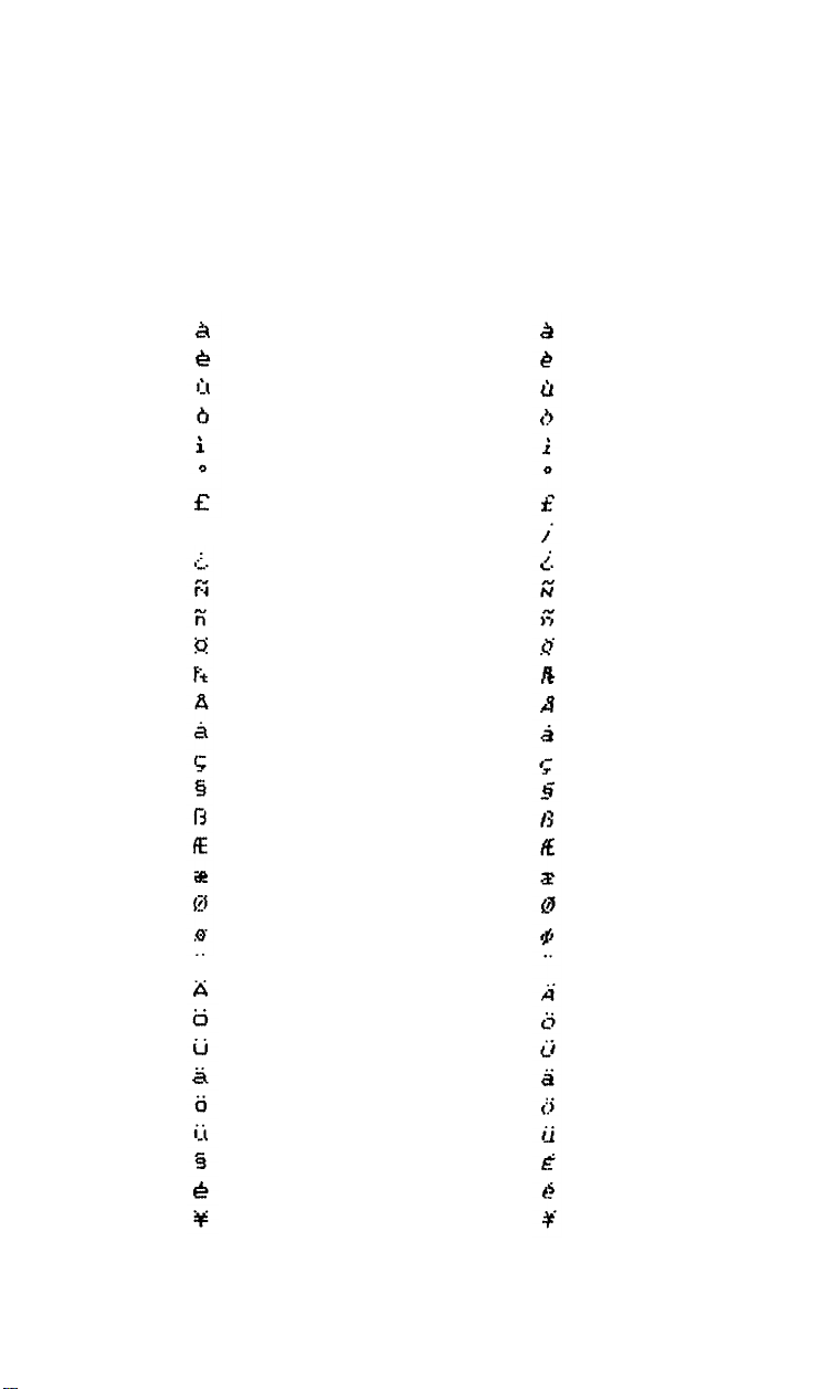
International characters summary
ASCII locations 0 to 31 and 128 to 159 store the international characters that are needed for sets other than the one for the USA. These
characters are printable only with the CHR$(27) “6”, CHR$(27) “I”, or
CHR$(27) “R” sequences.
Dec
0
1
2
3
4
5
6
7
8
9
11
19 13
20
21
22
23
24
25
26
27
28
29
30
31
Hex CHR
00
01
02
03
04
05
06
07
08
09
10
0A
0B
12
13
14
15
16 10
17
18
0C
OD
0E
0F
11
12
14
15
16
17
18
19
1A
1B
1C
1D
1E
1F
Dec Hex CHR
128
129
130
131
132 84
133
134
135
136
137
138
139
140
141
142
143
144
145
146
147
148 94
149
150
151
152
153
154
155
156
157
158
159
80
81
82
83
85
86
87
88
89
8A
8B
8C
8D
8E
8F
90
91
92
93
95
96
97
98
99
9A
9B
9C
9D
9E
9F
255
Page 11
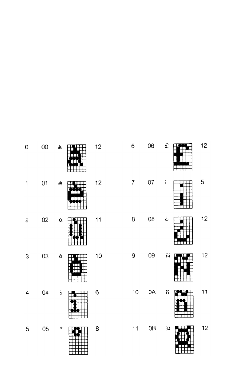
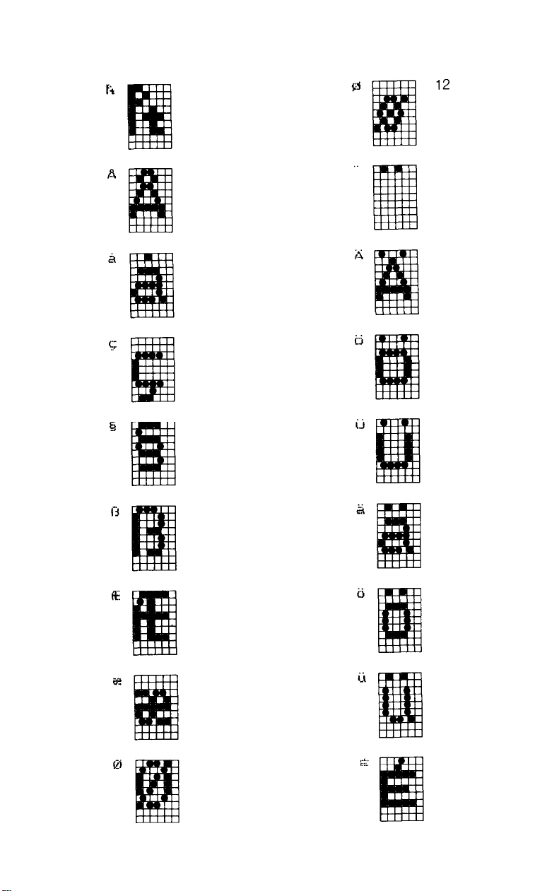
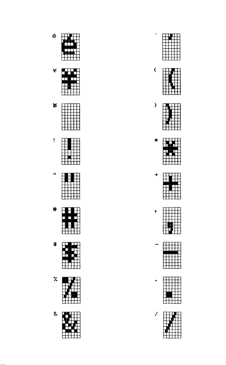
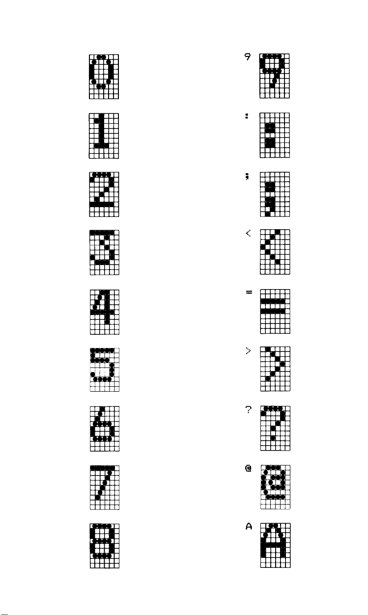
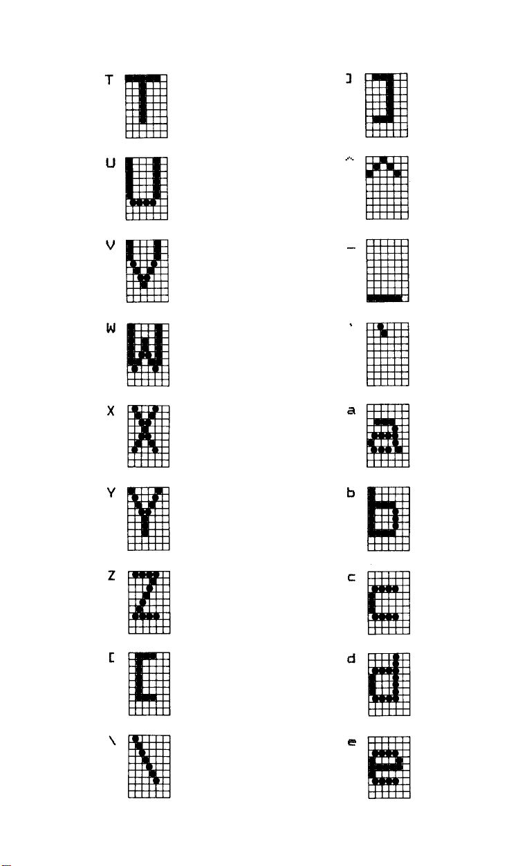
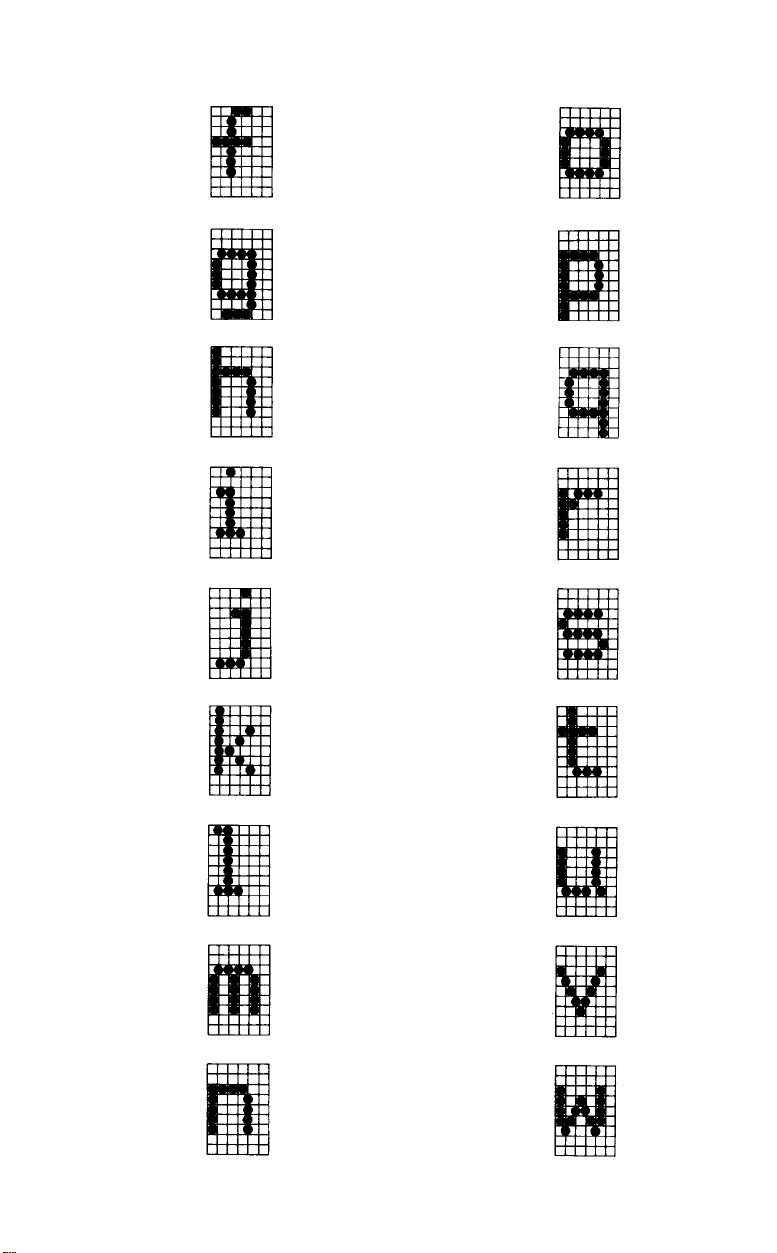
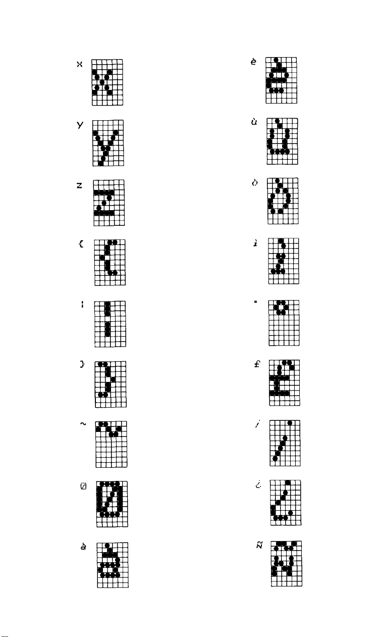
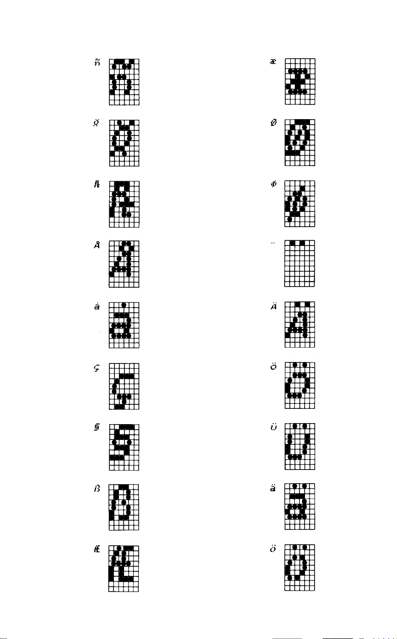
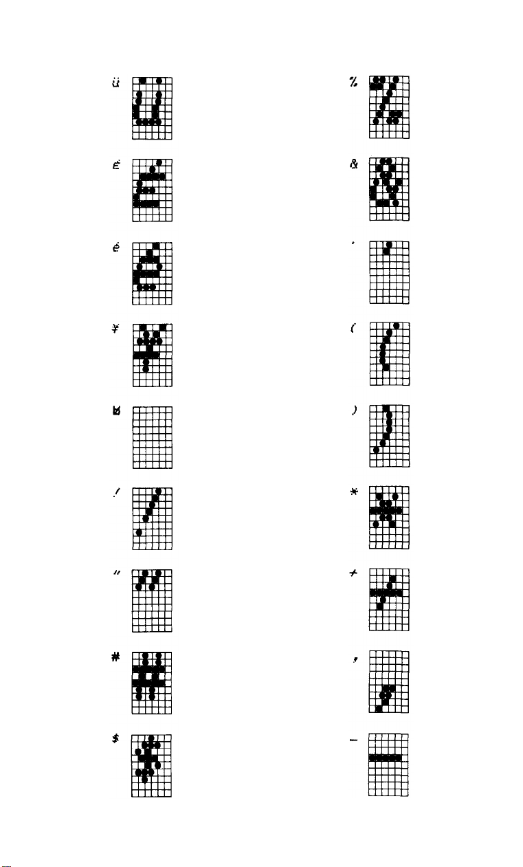
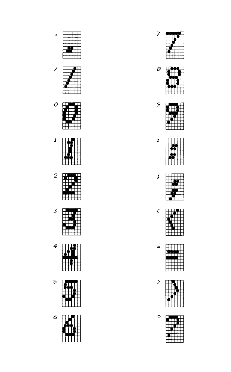
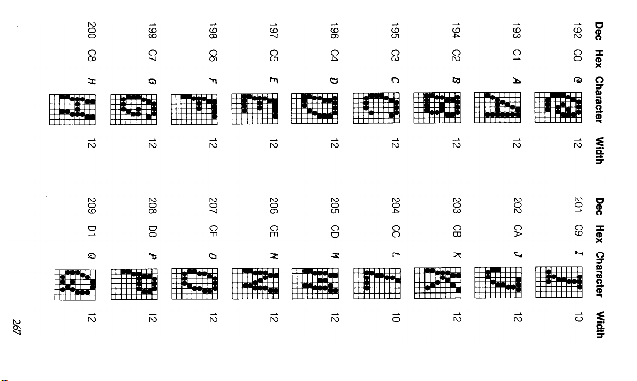
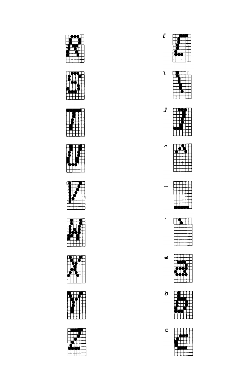
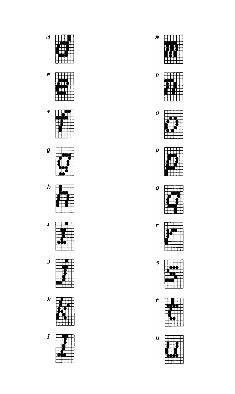
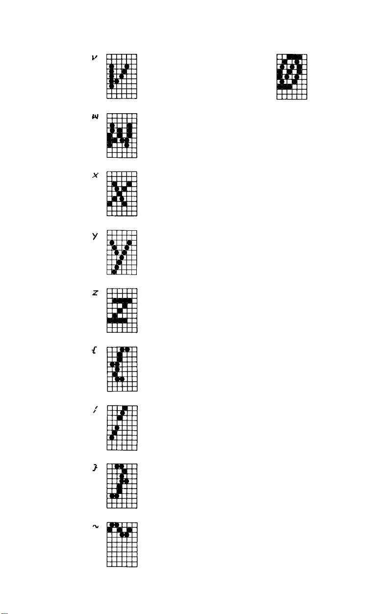
ASCII Character Matrixes
As in the summaries above, this section follows the ASCII code
arrangement, but this time we show the codes only as they are associated with characters—0 through 255. The characters for the Roman
and Italic USA fonts, which together make up the USA character set,
occupy ASCII positions 32 through 126 and 160 through 254, respectively. The international characters use ASCII positions 0 through 31
and 128 through 159. We show enlarged dot matrixes for both pairs of
fonts.
The width column shows the number of units used to print each
character in Proportional Mode. A unit is the width of one of the 12
columns in a character matrix (about half a dot).
Dec Hex
Character
Width
Dec
Character Width
Hex
256
Page 12
Dec
12
Hex
OC
Character
Width
12
Dec
21
Hex
15
Character
Width
13
14
15
16
17
OD
OE
OF
10
11
12
12
11
10
11
22
23
24
25
26
16
17
18
19
1A
8
12
12
12
12
18
19
20
12
13
14
12
12
12
27
28
29
1B
1C
1D
10
11
12
257
Page 13
Dec Hex Character Width Dec Hex Character Width
30
31
32
33
34
1E
1F
20
21
22
12
12
12
5
8
39 27
40 28
41
29
42
2A
43
2B
5
6
6
12
12
35
36
37
38
258
23
24
25
26
12
12
12
12
44
2C
45
2D
46 2E
47
2F
7
12
6
10
Page 14
Dec
Hex
Character
Width Dec Hex
Character
Width
48
49
50
51
52
30
31
32
33
34
57
58
59
60
61
39
3A
3B
3C
3D
12
8
2
3
4
12
12
12
12
6
6
10
12
53
54
55
56
35
36
37
38
5
6
7
8
12
12
12
12
3E
62
63
3F
646540
41
10
12
12
259
Page 15

Page 16
Dec
Hex
Character
Width
Dec
Hex
Character
Width
54
84
55
85
86 56
57
87
88 58
12
12
12
12
10
93
94
95
96
97
5D
5E
5F
60
61
a
12
12
5
12
89
90
91
92
59
5A
5B
5C
12
10
a
10
98
99
100
101
62
63
64
65
11
11
11
12
261
Page 17
Dec Hex Character
Width
Dec
Hex
Character
Width
102 66
103 67
104 68
105 69
106 6A
f
g
h
i
j
10
11
11
a
9
111
6F
112
70
71
113
114 72
115 73
o
p
q
r
s
12
11
11
11
12
107 6B
108 6C
109 6D
110 6E
262
k
l
m
n
10
a
12
11
116
117
118 76
119 77
74
75
t
u
v
w
11
12
12
12
Page 18
Dec Hex
Character
Width
Dec
Hex
Character
Width
120 78
121 79
122 7A
123 7B
124 7C
10
12
10
9
5
129
130
131
132
133
81
82
83
84
85
11
11
11
8
8
125 7D
126 7E
127 7F
128 80
9
12
12
11
134
135
136
137
86
87
88
89
12
10
11
12
263
Page 19
Dec Hex Character Width
Dec Hex Character Width
138
8A
139
8B
140
8C
141
8D
142 8E
12
12
12
12
11
147
148
149
150
151
93
94
95
96
97
12
12
11
9
12
143
144
145
146
264
8F
90
91
92
11
12
11
12
152
153
154
155
98
99
9A
9B
12
11
11
Page 20
Dec Hex
Character
Width
Dec
Hex
Character
Width
156
157
158
159
160
9C
9D
9E
9F
A0
12
12
11
12
12
165
166
167
168
169
A5
A6
A7
A8
A9
12
12
5
a
a
161
162
163
164
Al
A2
A3
A4
10
10
12
11
170
171
172
173
AA
AB
AC
AD
12
12
a
12
265
Page 21
Dec
Hex Character
174
AE
175
AF
176
B0
177
Bl
178
B2
Width
7
10
12
9
12
Dec
183
184
185
186
187
Hex
B7
B8
B9
BA
BB
Character
Width
12
12
11
8
9
179
180
181
182
266
B3
B4
B5
B6
12
12
12
11
188
BC
BD
189
190
191BEBF
10
11
9
11
Page 22
Page 23
Dec Hex Character Width
Dec
Hex
Character
Width
210
211
212
213
214
D2
D3
D4
D5
D6 V
DB
R
S
T
U
12
12
12
12
11
219
220
221
222
223
DC
DD
DE
DF
11
7
11
10
12
215
216
217
218
268
D7
D8
D9
DA Z
E0
W
X
Y
12
12
12
12
224
225
226
227
E1
E2
E3
5
11
11
11
Page 24
Dec Hex
Character
Width
Dec
Hex
Character
Width
228 E4
229 E5
230 E6
231 E7
232 E8
12
11
12
11
11
237
238
239
240
241
ED
EE
EF
FO
F1
11
10
11
11
11
233 E9
234 EA
235 EB
236 EC
9
10
11
9
242 F2
243 F3
244 F4
245 F5
10
11
10
11
269
Page 25
Dec Hex Character Width
Dec Hex Character Width
246 F6
247 F7
248
F8
249
F9
250
FA
10
12
12
11
12
255 FF
12
251
FB
252
FC
253
FD
254 FE
270
10
9
10
12
Page 26

Appendix B
Control Codes in Numeric Order
You activate an FX control code by using LPRINT CHR$(n), where
n is the number in the decimal column below. When the ESC column
contains a dash, you use only CHR$(n) but when ESC is written in this
ESC column, you must precede the CHR$(n) with CHR$(27). With
this ESCape sequence you may use a shortened form, the ESCape
code followed by the character in the symbol column in quotation
marks, as shown in the example below, the command that turns
Emphasized ON:
LPRINT CHR$(27) “E” .
Abbreviations: cpi = characters per inch
cps = characters per second
ESC Dec Hex Symbol Function
0 00 NUL
7 07 BEL
a 08 BS
9 09 HT
10 0A LF
Terminates horizontal and vertical tab setting.
Sounds beeper.
Backspace. Empties the printer buffer, then
moves the print head left 1 space in the
current pitch.
Horizontal tab. Empties the printer buffer,
then moves the print head to the next tab
stop.
Line feed. Empties the printer buffer, performs
a line feed at the current line spacing, and
resets the buffer character count to 0.
271
Page 27

ESC Dec Hex Symbol Function
- 11 0B VT
-
12 0C FF
-
13 0D CR
-
14 0E SO
- 15 0F SI
Vertical tab. Empties the printer buffer, then
advances the paper to the next vertical tab
stop.
Form feed. Empties the printer buffer, then
advances the paper to the next logical top of
form.
Carriage return. Prints the contents of the
buffer and resets the buffer character count
to 0. Restores the print head to the left
margin. You turn the automatic line feed on or
off with DIP switch 2-4.
Shift out. Turns Expanded Mode ON for the
length of the line unless cancelled by
CHR$(20) or CHR$(27)“WO”. Works with
Pica, Elite, or Compressed Mode.
Shift in. Empties the buffer and turns
Compressed Mode (17.16 cpi) ON. Cannot
work with Emphasized, Elite, Pica, or
Proportional Mode. Stays on until cancelled
by CHR$(18).
-
-
-
-
-
-
272
17
11
18
12
19 13
20
14
24
18
27
1B ESC
DC1
DC2
DC3
DC4
C AN
Device control 1. When 2-1 is OFF places the
printer in the active state: printer receives all
data sent to it.
Device control 2. Turns Compressed Mode
OFF
Device control 3. When DIP switch 2-1 is
OFF places the printer in the inactive state
until a DC1 code is received.
Device control 4. Turns the Expanded Mode
set by CHR$(14) OFF
Cancels all text in the print buffer.
Escape. Prepares the printer to receive
control codes.
Page 28

ESC Dec Hex Symbol Function
ESC 33 21 !
ESC 35 23 #
ESC 37 25
ESC 38 26 &
Master Print Mode Select (Master Select).
Selects 16 unique print mode combinations.
Format:
CHR$(27)” ! “CHR$(n)
where n = 0 - 255.
See Appendix D.
Accepts the eighth bit “as is” from the
computer.
%
Activates a character set. DIP switch 1-4
must be off. Format:
CHR$(27)” % “CHR$(0)CHR$(0)
selects the ROM set; and
CHR$(27)” % “CHR$(1)CHR$(0)
selects the RAM set.
Defines characters in user RAM. Format:
CHR$(27)“&“CHR$(0)CHR$(c1)CHR$(c2);
CHR$(a)CHR$(d1) . . . CHR$(d11);
where CHR$(0) is for future use, c1 is the
starting character, and c2 is the ending
character. Each character in the range c1 - c
2
requires an attribute byte (a) and 11 data
bytes (d1 - d11).
ESC 42 2A *
ESC 45 2D -
Turns Graphics Mode ON. Format:
CHR$(27)"
* “CHR$(m)CHR$(n1)CHR$(n2);
followed by n data numbers,
where n = n1 + 256*n2,
n, = 0 - 255,
n2 = 0 - 255,
m selects mode 0 - 6.
See Table 1 1-1 for modes.
Turns Underline Mode ON. Format:
CHR$(27)” - “CHR$(n)
where n toggles Underline on and off: 0 turns
it OFF 1 turns it ON.
273
Page 29

ESC Dec Hex Symbol Function
ESC 47 2F /
ESC
48
30 0
ESC
49
31
ESC 50 32 2
ESC
51
33
ESC
52
34
ESC
53
35
ESC
54
36 6
ESC 55 37 7
Selects a vertical tab channel.
Format:
CHR$(27)“/“CHR$(n)
where n
Sets line
1
3
4
5
Sets line
Returns line spacing to the default of 1/6 inch
(12-dot).
Sets line
1/3 dot). Stays on until changed. Format:
where n
Turns Italic Mode ON.
Turns Italic Mode OFF
Enables the printing of the Italic international
characters, which are stored in locations
128 - 159 and 255.
Turns off CHR$(27)“6”. Restores 126 - 159
and 255 to function as control codes.
= 0 - 7.
spacing to
spacing to
spacing to n/216-inch (1/216-inch
CHR$(27)“3”CHR$(n)
= 0 - 255.
1/8-inch (g-dot).
7/72-inch (7-dot).
is
ESC
56
38
ESC
57
39
ESC
58
3A
ESC 60 3C <
274
8
9
:
Disables the paper-out sensor.
Enables the paper-out sensor
Copies the ROM user-defined character set to
RAM. Format:
CHR$(27)“:“CHR$(n1)CHR$(n2)CHR$(n3);
where n1, n2, and n3 are all 0. (They are
included for future expansion.) The RAM
character set must be activated with
CHR$(27) " % “, and DIP switch 1-4 must be
off.
Turns 1-line Unidirectional Mode ON. Prints
each line from left to right.
Page 30

ESC Dec Hex Symbol Function
ESC 61 3D =
ESC 62 3E >
ESC 63 3F ?
ESC
64 40
ESC
65
41
ESC
66
42
A
@
B
Sets the eighth bit to 0 (limits the range to
0 - 127).
Sets the eighth bit to 1 (limits the range to
128 - 255).
Redefines one of the 4 alternate graphics
codes -- “K”,“L",“Y”, or “Z” - as one of the
seven graphics density numbers used with
the ESCape
“ * ” command. Format:
CHR$(27)“?s”;CHR$(n);
where s is K,L,Y, or Z and n is 0 - 6.
Reset Code, which resets the printer to its
power-up state, including resetting top of
form. Clears all text and control codes from
the print buffer.
Sets line spacing to n/72 inch (n-dot). Format:
CHR$(27)“A”CHR$(n)
where n = 0 - 85.
Sets up to 16 vertical tabs in the current line
spacing. Tab settings are not affected by
subsequent changes in line spacing. Format:
CHR$(27)“B”CHR$(n1)CHR$(n2). . .
CHR$(nK)CHR$(O)
where nk = 1 - 255. Terminate this tab
sequence with CHR$(0) or a number less
than that of the last tab (nk).
ESC 67 43 C
ESC 67 43 C
Sets the form length to n
lines
in the current
line spacing. The default is 66 lines. Also
resets top of form. Format:
CHR$(27)“C”CHR$(n)
where n = 1 - 127.
Sets the form length to n
inches,
regardless
of the current line spacing. The default is 11
inches. Also resets top of form. Format:
CHR$(27)“C”CHR$(0)CHR$(n)
where n = 1 - 22.
275
Page 31

ESC Dec Hex Symbol Function
ESC 68 44 D
ESC 69 45 E
ESC
70 46
ESC
71
47
ESC
72 48
ESC
73 49
Resets the current tabs and sets up to 32
horizontal tabs in the current pitch. Tabs may
range up to the maximum width for the
character and printer size. For example, the
maximum tab for Pica characters on an 8inch line is 79. Tab settings are not affected
by subsequent changes in pitch. Format:
CHR$(27)“D”CHR$(n1)CHR$(n2). . .
CHR$(nk)CHR$(O)
Terminate a tab sequence with CHR$(0) or a
number less than that of the last tab (nk).
Turns Emphasized Mode ON. Cannot mix with
Elite or Compressed Modes.
F
G
H
I
Turns Emphasized Mode OFF
Turns Double-Strike Mode ON.
Turns Double-Strike Mode OFF
Enables printing of the characters stored in
the ASCII locations 0 - 31 that are not
reserved for control codes. Symbols stored in
control-code locations must be printed with
CHR$(27)“R”. Format:
CHR$(27)“I”CHR$(n)
where n toggles the codes; 1 prints
characters, 0 prints control codes.
ESC 74 4A J
276
Forces an immediate line feed of n/21 6
inches without changing the current line
spacing. Prints the contents of the buffer
without a carriage return. Format:
CHR$(27)“J”CHR$(n)
where n = 0 - 255.
Page 32

ESC Dec Hex Symbol Function
ESC 75 4B K
ESC 76 4C L
ESC 77 4D M
Turns Single-Density Graphics Mode ON.
Prints 480 dots per 8-inch line. Format:
CHR$(27)“K”CHR$(n1)CHR$(n2);
followed by n data numbers, where
n = n1 + 256*n2,
n1 = 0 - 255,
n2 = 0 - 255.
For example, to print 480 dots, n1 = 224, n
2
= 1.
Turns Low-Speed Double-Density Graphics
Mode ON. Prints 960 dots per 8-inch line.
Format:
CHR$(27)“L”CHR$(n1)CHR$(n2)
followed by n data numbers, where
n = n1 + 256*n2,
n1 = 0- 255,
n2 = 0 - 255.
For example, to print 960 dots, n1 = 192, n
2
= 3.
Turns Elite Mode (12 cpi) ON. Cannot mix with
Pica, Proportional, Emphasized, or
Compressed Mode.
ESC 78 4E N
ESC 79 4F O
ESC 80 50 P
Sets skip-over-perforation to n lines. Format:
CHR$(27)”N”CHR$(n)
where n = 1 - 127.
Turns skip-over-perforation OFF
Turns Elite Mode OFF Returns to Pica unless
Compressed Mode is active.
277
Page 33

ESC Dec Hex Symbol Function
ESC 81 51 Q
ESC 82 52 R
ESC 83 53 S
ESC 84 54 T
Sets the right margin. Also cancels all text
that is in the print buffer. Format:
CHR$(27)“Q”CHR$(n)
where n = 1 - maximum number of
characters per line in the current pitch:
FX-80
2-80
3-96
4-137
FX-100
2-136 in Pica
3-163 in Elite
4-233 in Compressed
Selects an international character set by its
country’s number. See Tables 6-2 and 6-3.
Format:
CHR$(27)“R”CHR$(n)
where n = 0 - 8.
Turns Script Mode ON. Either type of Script is
printed in Double-Strike; neither can mix with
Proportional Mode. Format:
CHR$(27)“S”CHR$(n)
where n = 0 produces Superscript, and 1
produces Subscript.
Turns Script Mode OFF
ESC 85 55 U
ESC 87 57 W
278
Turns Unidirectional Mode ON. Prints each
line from left to right. Format:
CHR$(27)“U”CHR$(n)
where n toggles the mode on and off:
0 turns it OFF 1 turns it ON.
Turns Expanded Mode ON; stays ON until
turned OFF Cannot be turned off with
CHR$(20). Format:
CHR$(27)“W”CHR$(n)
where n toggles the mode on and off:
0 turns it OFF 1 turns it ON.
Page 34

ESC Dec Hex Symbol Function
ESC 89 59 Y
ESC 90 5A Z
ESC 94 5E ˆ
Turns High-Speed Double-Density Graphics
Mode ON; gives the same density as
CHR$(27)” L”, but cannot print two adjacent
dots in the same row.
Turns Quadruple-Density Graphics Mode ON.
Prints 1920 dots per 8-inch line. Format:
CHR$(27)“Z”CHR$(n1)CHR$(n2)
followed by n data numbers, where
n = n, + 256*n2,
n1 = 0 - 255,
n2 = 0 - 255.
For example, to print 1920 dots on the FX-80
n1 = 128, n2 = 7. On the FX-100, to print
3264 dots, n1 = 192, n2 = 12.
Turns Nine-Pin Graphics ON. Format:
CHR$(27)“ˆ“CHR$(d)CHR$(n1)CHR$(n2);
followed by 2 times n data numbers
where n = n1 + 255* n
2
n1 = 0 - 255.
n2 = 0 - 255.
The printer expects 2 data numbers for each
column of print. The d selects the density,
where 0 produces Single-Density and 1
produces Double-Density
ESC 98 62 b
ESC 105 69 i
Sets the vertical tab for channel n. Format:
CHR$(27)“b”CHR$(n);
where n = 0 - 7,
and n = 0 is the same as CHR$(27)“B”.
On the FX-80 only, turns Immediate Mode
ON. Prints each character immediately as it
is received by the printer. Format:
CHR$(27)“i”CHR$(n)
where n toggles Immediate on and off: 0
turns it OFF; and 1 turns it ON.
279
Page 35

ESC Dec Hex Symbol Function
ESC 106 6A j
ESC 108 6C I
ESC 112 70 p
ESC 115 73 s
On the FX-80 only, causes an immediate
reverse line feed in an increment of 1/216inch without a carriage return. Similar to
CHR$(27)“J”. Format:
CHR$(27)“j”CHR$(n)
where n = 0 - 255.
Sets the left margin. Format:
CHR$(27)“I”CHR$(n)
where n ranges from:
FX-80
0 - 78 0-134
0 - 93
0-133 0-229
FX-100
0-160
in Pica
in Elite
in Compressed
Turns Proportional Mode ON. Cannot mix with
Elite, Emphasized, Compressed, Script, or
Double-Strike Mode. Format:
CHR$(27)“p”CHR$(n)
where n toggles Proportional on and off: 0
turns it OFF and 1 turns it ON.
Selects the print speed. Half-Speed Mode can
be employed to reduce noise. Format:
CHR$(27)“s”CHR$(n)
where n toggles Half-Speed on and off, so
that 1 produces 80 cps, while 0 produces 160
cps.
-
127 7F DEL
280
Deletes the last text character in the print
buffer.
Page 36

The printer’s high-order control codes from 128 to 155 and 255 mir-
ror their low-order counterparts (0 - 27 and 127). For ready reference,
both sets are listed here:
Low
Dec Dec
0
7
8 136
9 137
10
11
12
13
14
15
17
18
19
20
24
27
127
High
128
135
138
139
140
141
142 8E SO
143
145
146
147
148
152
155
255
High
Hex
80 NUL
87 BEL
88
89
8A
8B
8C
8D
8F
91 DC1
92
93
93
97
9B
FF
Symbol
BS
HT
LF
VT
FF
CR
SI
DC2
DC3
DC4
CAN
ESC
DEL
Function
Terminates horizontal and vertical tab
setting.
Sounds beeper.
Backspace.
Horizontal tab.
Line feed.
Vertical tab.
Form feed.
Carriage return.
Shift out; turns Expanded Mode ON.
Shift in; turns Compressed Mode ON.
Device control 1; activates printer.
Device control 2; turns Compressed
Mode OFF:
Device control 3; deactivates printer.
Device control 4; turns the Expanded
Mode set by (CHR$(14) OFF:
Cancels all text in the print buffer.
Escape code.
Deletes the last text character in the
print buffer.
281
Page 37

282
Page 38

Appendix C
Control Codes by Function
This Appendix shows the same control codes as Appendix B, but
this time arranged by categories before ASCII order. If your computer
cannot generate lowercase letters, use the equivalent decimal ASCII
values. See Appendix B or refer to the pages suggested by the Index for
usage instructions.
Character Width (Pitch)
CHR$(27)“M”
CHR$(27) "P"
CHR$(15)
CHR$(18)
CHR$(14)
CHR$(20)
CHR$(27)“W0”
CHR$(27)“W1”
CHR$(27)“p0”
CHR$(27)“p1”
Turns Elite Mode ON.
Turns Elite Mode OFF.
Turns Compressed Mode ON.
Turns Compressed Mode OFF.
Turns one-Line Expanded Mode ON.
Turns one-Line Expanded Mode OFF.
Turns Expanded Mode OFF.
Turns continuous Expanded Mode ON.
Turns Proportional Mode OFF.
Turns Proportional Mode ON.
Character Weight
CHR$(27)“E”
CHR$(27) “F”
CHR$(27)“G”
CHR$(27)“H”
Turns Emphasized Mode ON.
Turns Emphasized Mode OFF.
Turns Double-Strike Mode ON.
Turns Double-Strike Mode OFF.
283
Page 39

Print Enhancement
CHR$(27)“S0”
CHR$(27)“S1”
CHR$(27)“T”
CHR$(27)"-0”
CHR$(27)“-1”
Turns Superscript Mode ON.
Turns Subscript Mode ON.
Turns either Script Mode OFF.
Turns Underline Mode OFF.
Turns Underline Mode ON.
Mode and Character-Set Selection
CHR$(27)“!"CHR$(n)
Master Select.
CHR$(27)”%“CHR$(n1)CHR$(n2)
Selects a character set by source: ROM
(factory) or RAM (user-defined).
CHR$(27)“&“CHR$(n)CHR$(c1)CHR$(c2)CHR$(A)CHR$(d1)...
CHR$(d11)
CHR$(27)“4”
CHR$(27)"5"
CHR$(27)“6”
CHR$(27)“7”
CHR$(27)“:“CHR$(n1)CHR$(n2)CHR$(n3)
CHR$(27)”@”
CHR$(27)“I0”
CHR$(27)“I1”
CHR$(27)“R” CHR$(n)
Defines characters c1 to c2 in RAM area; n is 0.
Each character requires an attribute byte (A),
followed by
Turns Italic Mode ON.
Turns Italic Mode OFF.
Enables printing of characters stored at ASCII
11
data numbers (d1 to d11).
128 - 159.
Causes codes 128 - 159 to print as control
codes.
Copies ROM characters to the user RAM area.
Reset Code.
Causes codes 0 - 31 to print as control codes.
Enables printing of characters stored at ASCII
0 - 31 that are not used as control codes.
Selects an international character set.
Special Printer Features
CHR$(7)
CHR$(8)
CHR$(17)
CHR$(19)
CHR$(24)
CHR$(27)“#”
284
Sounds the beeper.
Backspaces.
Enables the printer to receive data.
Disables the printer from receiving data.
Cancels the text in the print buffer.
Accepts the high-order bit “as is” from the
computer.
Page 40

CHR$(27)” < ”
CHR$(27)” = ”
CHR$(27)” > "
CHR$(27)“ U0 ”
CHR$(27)“Ul”
CHRS(27)“i0”
CHR$(27) “il”
CHR$(27)“s0”
CHR$(27)“sl”
CHR$(127)
Turns One-Line Unidirectional Mode ON.
Sets the high-order bit OFF.
Sets the high-order bit ON.
Turns Continuous Unidirectional Mode OFF.
Turns Continuous Unidirectional Mode ON.
Turns Immediate Mode OFF.
Turns Immediate Mode ON.
Returns to normal speed.
Turns Half-Speed Mode ON.
Deletes the most recent text character in the
print buffer.
Line Spacing
CHR$(10)
CHR$(27)“0” Sets line spacing to 1/8-inch.
CHR$(27)“1” Sets line spacing to 7/72-inch.
CHR$(27)“2” Sets line spacing to 1/6-inch (default).
CHR$(27)“A”CHR$(n)
CHR$(27)“3”CHR$(n)
CHR$(27)“J”CHR$(n)
CHRS(27)” j “CHR$(n)
Produces a line feed.
Sets line spacing to n/72-inch.
Sets line spacing to n/216-inch.
Produces an immediate one-time line feed of
n/216-inch without a carriage return.
Produces an immediate one-time reverse feed
of n/216-inch without a carriage return.
Forms Control
CHR$(27)“8” Turns the paper-out sensor OFF.
CHR$(27)“9” Turns the paper-out sensor ON.
CHR$(12)
CHR$(13)
CHR$(27)“C”CHR$(0)CHR$(n)
CHR$(27)“C”CHR$(n)
CHR$(27)“N”CHR$(n)
CHR$(27) “O"
Produces a form feed.
Produces a carriage return.
Sets the form length in inches.
Sets the form length in lines.
Turns a variable skip-over-perforation ON.
Turns skip-over-perforation OFF.
285
Page 41

Page Format
CHR$(9) or CHR$(137)
Activates a horizontal tab.
CHR$(1l)
CHR$(27)" / “ CHR$(n)
CHR$(27)“B"CHR$(n1) . . . CHR$(nk)CHR$(0)
CHR$(27)“D”CHR$(n1) . . . CHR$(n
CHR$(27)“Q”CHR$(n)
CHR$(27)“b”CHR$(n)CHR$(n2)CHR$(n2) . . . CHR$(nk)CHR$(0)
CHR$(27)“1”CHR$(n)
Activates a vertical tab.
Selects a vertical tab channel.
Sets vertical tab stops.
)CHR$(0)
Sets horizontal tab stops.
Sets the right margin.
Stores vertical tab stops in a channel.
Sets the left margin.
k
Dot Graphics
CHR$(2ˆX)
CHR$(27)”*“CHR$(n)CHR$(n1)CHR$(n2);
CHR$(27)“?s”CHR$(n)
CHR$(27)“K”CHR$(n1)CHR$(n2);
CHR$(27)“L”CHR$(n1)CHR$(n2);
CHR$(27)“Y“CHR$(n1)CHR$(n2);
CHR$(27)“Z”CHR$(n1)CHR$(n2);
When sent as graphics data fires pin X, where
x=0-7.
Selects one of six graphics densities.
Reassigns a code letter s to a graphics density
n, where s = K, L, Y, or Z and n = 0 - 6.
Turns Single-Density Graphics Mode ON.
Turns Double-Density Graphics Mode ON.
Turns High-Speed Double-Density Graphics
Mode ON.
Turns Quadruple-Density Graphics Mode
CHR$(27)"ˆ"CHR$(0)CHR$(n1)CHR$(n2);
Turns Single-Density Nine-Pin Graphics Mode
CHR$(27)"ˆ"CHR$(l)CHR$(n1)CHRS(n2);
Turns Double-Density Nine-Pin Graphics
Mode ON.
286
Page 42

Appendix D
Control Code Comparison
The first part of this appendix consists of a chart of the commands
used on Epson printers. It shows similarities and differences between
the MX III, the FX, and the RX. Unless otherwise specified, the FX
column applies to both the FX-80 and the FX-100, and the RX column
applies to both the
In the second part of this chapter, we summarize the differences in
software and then cover variations in hardware features. The commands, both in the chart and in the prose summary, are arranged in
ASCII order.
Control Code Chart
ASCII ASCII
Dec symbol
7
BEL
8
BS
9
HT
10
LF
VT
11
12 FF
13 CR
14 SO
15 SI
17 DC1
18
DC2
19
DC3
20 DC4
24
CAN
27
ESC
33
ESC ! Selects mode combinations
35 ESC # Cancels MSB function
RX-80
and the
Function
Sounds beeper
Backspace
Horizontal Tabulation
Line Feed
Vertical Tabulation
Form Feed * I*
Carriage Return
Shift Out; Expanded (1-line) on
Shift In; Compressed on
Activates the printer
Compressed Mode off
Deactivates the printer
Expanded Mode (1 -line) off
CANcels text in print buffer
Escape code
RX-100.
MXIII FX RX
*
* * *
* * *
*
*
* * *
*
*
*
*
*
*
*
*
*
*
I*
* *
*
*
*
*
*
*
*
*
*
*
*
*
*
*
RX-100
*
287
Page 43

288
Page 44

Epson Model Differences
In this discussion of software and hardware differences between the
MX III, the FX and the RX, the command name (backspace, vertical
tab, etc.) is that of the most recent model which carries it.
CHR$(8) - Backspacing
On the MX III in Expanded Mode, moves the print head to the left
one Pica position.
On the FX and RX in all six pitches, moves the print head to the left
one position in the current pitch.
CHR$(9) or CHR$(137) - Default horizontal tabbing
See CHR$(27)“D” and CHR$(27)“e”.
CHR$(11) - Vertical tabbing
On the MX III, prints a line feed.
On the FX and RX, activates a vertical tab. See also
ESCape “e”.
289
Page 45

CHR$(15) - Compressed Mode selection
On the MX III, prints 132 characters per 8-inch line.
On the FX-80 and RX-80, prints 132 characters per 8-inch line, but
can print 137 characters if the right margin is changed. On the FX-100
and RX-100 prints 233 characters per 13.6-inch line.
CHR$(17) and CHR$(19) - Printer selection
On the FX only and only with DIP switch 2-1 off, turns printing on
and off. When CHR$(19) is in effect, the printer ignores all output.
CHR$(24) - Cancelling text
On the FX and RX-100 only erases all text from the buffer; does not
erase control codes from the buffer.
ESCape ” ! ” -
On the FX only, selects one of 16 print mode combinations. Any
one of these may also be combined with other print modes.
Escape”#” , ” > ” and " = " - MSB control
On the MX III and the FX, these three codes allow 7-bit system users
to print high-order control codes by manipulating the most significant
bit.
ESCape ” % ” ,
On the FX only, lets you design your own characters and store them
in RAM. You can use them alone or in combination with the standard
FX characters.
Escape ”*” -
On all three models, ESCape”K” and “L” provide two Graphics
Modes.
On both the FX and the RX, Escape”*” adds four more graphics
densities: 80, 90, 120, and 140 dots per inch.
On the FX only, adds a fifth, 72 dots per inch.
ESCape ” - ” - Underlining
On all three models, the underline character is five dots wide.
On the MX-III, this code dumps the buffer and, when a space is
placed at the beginning or end of a line, the printer ignores it.
On the FX, the underline code does not empty the buffer and spaces
can occur (and thus be underlined) at the beginning or end of a line.
On the RX, the underline code does dump the buffer and spaces can
occur (and thus be underlined) at the beginning or end of a line.
Master Print Mode selection
” : ‘, and ” &" - Custom character definition
Special Graphics Mode selection
Page 46

Escape”/” ,
On the FX and RX-100 only lets you set up to 16 vertical tabs and
store up to eight vertical tab channels in memory.
ESCape “3" - Special line spacing
On all three models, you can set and reset the line feed function by
changing hardware (DIP switch and/or cable wiring).
On the FX and RX, this code provides n/216-inch line spacing and
incidentally controls the automatic line feed function.
ESCape”4” - Italic Mode selection
On all three models, prints in the Italic version of the current pitch.
On the FX only, also empties the buffer.
ESCape “6” and “7” - Special character selection
On the FX only, lets you print the characters that are stored behind
control codes 128 to 159 and 255.
Escape”?” - Graphics code reassignment.
On the FX reassigns alternate graphics codes to one of seven density
settings.
On the RX-100 only, reassigns alternate graphics codes to one of six
density settings.
ESCape”A” - Special line spacing
On all three models, you can set and reset the line feed function by
changing hardware (DIP switch and/or cable wiring).
On the FX and RX, this code provides n/72-inch line spacing and
incidentally controls the automatic line feed function.
“B”, and “b” - Vertical tabbing
ESCape”B” - Vertical tabbing. See Escape”/” .
ESCape”D” - Horizontal tabbing
On the MX III, you set horizontal tabs in the current pitch when
that is Pica, Elite, or Compressed (Emphasized does not affect the settings). The positions of horizontal tabs change with subsequent
changes in pitch, and zero is the terminator character.
On the FX and RX-100 only, you set horizontal tabs in the current
pitch. Horizontal tab stops remain located at the positions that you set
regardless of any subsequent changes in pitch, and you can terminate
them with any value less than or equal to that of the last tab stop.
Default tab settings do change when Expanded Mode is in effect.
For the RX-80, see ESCape”e”.
291
Page 47

Escape ” G” - Double-Strike Mode selection
On the MX III, FX-100, and RX, moving in and out of Double-
Strike Mode on one line produces a descent of one-third dot per
change.
ESCape ”H” - Double-Strike Mode selection
On the MX III, this code also cancels Script Mode.
ESCape ” I ” - Special character selection
On the FX only, you can use this code as a toggle (with 0 and
1)
which allows you to print the characters stored behind control codes 0
to 31. ESCape”I” will not work on those codes needed by the printer.
ESCape ”K”- Graphics Mode selection with the format
ESCape”K”CHR$(n1)CHR$(n2)
On the MX III, this code is invalid when the high-order bit is set,
and n2 works modulo 8.
On the FX, users of 7-bit systems can use this code with the high-
order bit set, but n2 will not work modulo 8.
On the RX, this code works with the high-order bit set, and n
does
2
work modulo 8.
ESCape ”M” and “P" - Elite Mode selection
On the FX and RX, prints in Elite (12 characters per inch), which
matches the pitch used on many typewriters. ESCape”M” selects Elite
and “P” returns the printer to the default mode.
ESCape ”R” - International character set selection
On the RX, lets you select from 11 international character sets.
On the FX only, lets you select from 9 international character sets:
also prints the contents of the buffer.
Escape ”S” and “T” - Script Mode selection
On the MX III, Script characters cannot be printed in Expanded or
Emphasized Mode; ESCape”H” cancels not only Double-Strike Mode
but also both Script Modes; and ESCape”T” returns the printer to
Double-Strike.
On the FX and RX, Script characters can be printed in Expanded or
Emphasized; Escape”H”
cancels only Double-Strike; and
ESCape”T” returns the printer to the previous mode, whether it was
Single- or Double-Strike.
See also ESCape ”G”.
292
Page 48

ESCape ”Y" - High-Speed Double-Density Graphics Mode selection
On the FX and RX, prints ESCape”L” graphics at twice the usual
speed. There is one limitation: it will not print adjacent dots in the
same row.
ESCape “Z” - Quadruple-Density Graphics Mode selection
On the FX and RX, prints 1920 dots per B-inch line; on the FX-100
and RX-100, prints 3264 dots per 13.6-inch line.
Escape ”^” -
On the FX and RX-100 only, speeds up screen dumps.
ESCape ”b” - Vertical tabbing. See Escape ”/” .
ESCape ”e” - Horizontal and vertical tabbing
On the RX-80 only, lets you set an increment to be used by
CHR$(9), CHR$(137),
you set horizontal tabs in Pica pitch. After a tab is set, subsequent
changes in line spacing or pitch do not affect its position.
Escape ”f” - Special horizontal and vertical spacing
On the RX-80 only, lets you print up to 127 horizontal spaces or
vertical line feeds.
ESCape ”i” - Immediate printing
On the FX-80 only, causes character-by-character printing, as on a
typewriter.
Escape ”j” - Reverse line-feed selection
On the FX-80 only, causes a reverse line feed of n/216-inch in the
current column.
ESCape ”1” - Left margin selection
On the FX-80 and RX-80, lets you set the left margin for an B-inch
line at 0 to 78 in Pica, 0 to 93 in Elite, and 0 to 133 in Compressed. On
the RX-100 and FX-100, lets you set the left margin for a 13.6-inch line
at 0 to 134 in Pica, 0 to 160 in Elite, and 0 to 229 in Compressed.
Nine-pin Graphics Mode selection
or CHR$(11). Regardless of the current pitch,
ESCape ”m”
On the RX only, lets you print the graphics characters which are
stored behind control codes 128 to 159.
ESCape ”p” - Proportional Mode selection
On the FX only, prints characters proportionally, without excess
space, in Emphasized Mode.
- Graphics character selection
293
Page 49

ESCape”s”
- Half-speed printing
On the FX, prints at half the normal speed, which results in 80 char-
acters per second.
On the RX, prints at half the normal speed, which results in 50
characters per second.
Dumping programs in hexadecimal
On the FX and RX, you can use the hex dumping facility to aid you
in debugging. All codes sent to the printer are dumped onto the paper
in their hex format, which lets you see exactly what the printer is
receiving from the computer.
You turn this facility on as you turn the printer on. As you turn on
the FX, hold down the FF button. As you turn on the RX, hold down
both the FF and LF buttons. For either model, you stop dumping in
hex by turning off the printer.
The FX-80 prints the hex dump at 20 numbers per line; this leaves 2
spaces between each pair of numbers. The FX-100 prints the hex dump
at 34 numbers per line; this leaves 2 spaces between each pair of numbers.
The RX-80 prints the hex dump at 26 numbers per line; this leaves 1
space between each number.
Alarms
The FX and RX have different alarms for the various error conditions. See Appendix F.
Typestyles
On the FX and RX, you can print in 128 typestyles.
DIP switches
Each model has its own arrangement of DIP switches. See Appendix E.
Pin feeder
Only the FX-80 has a built-in pin feeder.
Page 50

Appendix E
Defaults and DIP Switches
In this Appendix we list the default settings for your printer, showing which settings you can change and the way you can change them.
Some of the defaults can be changed by using DIP switches; the second section illustrates and discusses those defaults.
Default Settings
When your FX comes from the factory, it is set to the following
defaults. An asterisk (*) means that you can change the default for
this setting by changing a DIP switch, while a bullet (•) means that
you can change this setting in a program, by using an ESCape code.
* l Printer activated
l
Roman character font
* l Pica pitch
l
Margins set at maximums: left margin at 0, and, since the default
is Pica, the right margin at 80 on the FX-80 and at 136 on the
FX-100
l
12-dot line spacing
l
66 lines (11 inches of default line spacing)
l
Vertical tabs set at every two lines
l
Vertical tab channel 0 selected
l
Horizontal tabs set at every eight spaces
* l USA character set
295
Page 51

*
2K buffer available for user-defined characters
* l Paper-out sensor on
*
Non-slashed zero (although there’s no code for “turning on”
slashed zero, you can slash one zero at a time with backspace)
*
Carriage return issued at the end of a line without an automatic
line feed
l
Bidirectional movement of the print head
* l Skip-over-perforation feature off
*
Beeper on (turning off the paper-out sensor deactivates the
beeper for this function but not for others)
Top of form occurs at the position of the print head when you
reset the printer-by turning power on or by issuing an ESCape
”@“-or when you change the form length with either format of
ESCape “C”.
DIP Switches
The FX printers have two sets of internal switches which are used by
the printer to determine the default mode on power-up. The switches
are under the upper right vent. As outlined in Chapter 1, the vent
screw must be removed with a Phillips-head screwdriver in order to
take the cover off.
Since switch settings are only checked by the printer on power-up,
all switch setting should be done with the power off. The printer will
not recognize changes made in switch settings when the power is on
until the printer is turned off and then on again.
The factory sets and numbers the switches in the following way:
296
Page 52

Table E-1. DIP switch function
Switch 1
Note: The
shaded boxes show the factory settings.
OFF
Figure E-Z. Factory setting of the DIP switches
Examining the Switches
Switches 1-6, 1-7, and 1-8 determine the active international char-
acter set as shown on the next page:
297
Page 53

Table E-2. International DIP switch settings
See Chapter 6 for a discussion of the international sets.
Switch 1-5: selects a default print weight. When it is ON, Emphasized
is the default. When it is OFF, Single-Strike is the default.
Switch 7-4: controls the RAM memory. When it is ON, makes a 2K
buffer available. When it is OFF, that memory can be used for user-
defined characters.
Switch 1-3: controls the paper-out sensor. When it is ON, the sensor is
deactivated, and printing will continue even when paper is out
(printer stays on-line). When it is OFF, printing stops when the printer
runs out of paper. The printer goes off-line (and the beeper sounds if
switch
2-2
is on).
Switch 1-2: controls the printing of zeroes. When it is ON, the FX
prints a slashed zero (0). When it is OFF, a normal zero is printed.
Switch 1-1: selects a default pitch. When it is ON Compressed Mode
becomes the default. When it is OFF, Pica is the default. If both switch
1-5
and switch
Compressed.
1-1
are ON, Emphasized Mode takes priority over
Switch 2-4: controls the line feed. When it is ON, the printer produces
an automatic line feed with every carriage return. When it is OFF no
line feed is added (line feed must be provided by computer).
Switch
a form feed is produced one inch from the bottom of every form. Note
that the top of form is set when the printer is turned ON. This switch is
used primarily to skip automatically over the paper perforation of
fanfold paper. When it is OFF, no skip is made. See chapter 8 for
details.
2-3:
controls the skip-over perforation feature. When it is ON,
298
Page 54

Switch 2-2: controls the beeper. When it is ON, the beeper sounds
when it receives a CHR$(7) or to indicate the paper has run out. When
it is OFF, CHR$(7) or paper-out doesn’t sound beeper.
For printer detected error other than paper-out sensing (for which
switch
setting of switch 2-2.
1-3
must also be set), the beeper will sound regardless of the
Switch 2-1: selects the printer. When it is ON, it activates the SLCT IN
signal and the printer actively processes commands sent from the
computer; it cannot be deactivated with software codes. When it is
OFF, the printer can be activated and deactivated by external software
codes. CHR$(17) (DCl) activates or turns on printing, and CHR$(19)
(DC3) deactivates or turns off printing. While the printer is inactive,
all input data is ignored (until the printer is reactivated by CHR$(17)).
299
Page 55

300
Page 56

Appendix F
Troubleshooting
This appendix approaches troubleshooting from several directions.
The first section uses a columnar format to match solutions with problems. Other sections cover beeper error warnings, hexadecimal code
dumping, coding and seven-bit solutions, and specific solutions for
several popular personal computer systems.
Problem/Solution Summary
The left column below will help you in identifying the source of
your problem and start you on the way to finding a solution.
Problem
Setting print styles
Can’t get Compressed print.
Doesn’t go back to Pica print
when Proportional Mode is cancelled.
Solution
Cancel Emphasized, Elite and/or
Proportional Modes. They have
priority over Compressed. Be
sure that DIP switch
for Emphasized.
Proportional print masks other
modes. When it is cancelled, the
printer returns to the mode that it
was in prior to Proportional. To
get back to Pica, cancel all other
modes.
1-5
is not set
301
Page 57

Changing form measurements
The ESCape”C” command is not
working properly.
The ESCape“N” skip-over-perforation doesn’t work.
Tabbing
Vertical tabs don’t work correctly.
Horizontal tabs don’t work correctly.
Horizontal tabs are incorrect
when changing pitch.
Graphics
Strange things print.
Don’t set, form lengths of 0 or
128.
Don’t set the skip larger than the
form length.
Can’t set vertical tabs greater
than the form length. Each tab
sequence must be terminated by a
CHR$(0) or a number less than
the last tab value.
Each tab sequence must be terminated by a CHR$(0) or a number
less than the last tab value.
Tabs are set according to current
print pitch. Changes in pitch do
not affect the position of the tabs
on the page.
Some systems require a WIDTH
statement. See your system docu-
mentation.
Many computers have problems
sending one or more of the codes
0 and 8 - 13. Avoid any that affect
your
Alternatively, you can substitute
the high-order versions, or you
can POKE the problem codes
directly to the printer.
system
if possible.
302
Seven-bit computers cannot use
the eighth pin (128). If you have a
7-bit computer and your pin
sequence is larger than 127,
change it.
Page 58

Printer “freezes” in Graphics
Mode.
The printer expects a certain
number of pin patterns, determined by n1 and n2. It will wait
patiently until the quota is full.
Note that 9-Pin Graphics Mode
requires two bytes for each column of graphics.
Can’t get a full page in width.
Having trouble getting into
Graphics Mode.
User-Defined Characters
The last character is swallowed
by the printer . . . nothing gets
printed.
Characters are one dot too high
or low.
Some systems require a WIDTH
statement. See your system documentation.
Seven-bit computers are limited
to widths of 0 - 127, 256 - 383, 512
- 639,
Make sure the high-order bit is
OFF. For 7-bit computers, that
means sending the code: ESCape
" = "
Make sure the attribute byte is
sent before the 11-pin patterns for
EACH character.
Use the correct setting for the
attribute byte. An attribute byte
less than 128 makes the bottom 8
pins active (good for descenders).
An attribute byte of 128 or
greater activates the top 8
(matching ROM characters without descenders).
etc. See below.
Characters are running too close
together.
Some of the dots are being
ignored by the printer.
You must reserve space between
characters within the character
design. Typically, the last 2 columns are defined as 0. See the
matrixes for ROM characters in
Appendix A.
Two dots in the same row cannot
be printed in adjacent columns.
Page 59

Loading paper
Paper goes crooked as it rolls
down.
Paper crunches up.
Top edge of paper sticks under
the roller.
Paper-out sensor
Can’t deactivate paper-out sensor
with DIP switch 1-3 or ESCape
"8".
It may be running against the ribbon guide. Move the printhead to
the middle of its path.
The paper guides are set incorrectly. Move them to fit this
paper.
If your paper is thin, doubling the
first page may give enough rigidity to ease it through the guides.
For subsequent loading, tape the
first page of a new batch of paper
to the last page of an old batch,
thus avoiding reloading.
There may be bits of paper
caught under the roller. Stop
inserting paper; turn the roller
and extract any paper bits with
fingers or tweezers.
Computer systems that monitor
printer cable pin 12 will ignore
both ESCape “8” and the setting
of switch
stop the printing when no paper
is in contact with the paper-out
sensor (a reed switch located on
the paper guide). Certain printer
cables are designed to overcome
this problem, or you can tape a
business card over the switch.
1-3.
These systems will
Beeper Error Warnings
The FX will warn you of certain error conditions by sounding the
internal beeper. Each of the four error conditions has a unique sound.
Listen closely . . .
304
Page 60

1. A short circuit between the collector and the emitter of a head transistor along with a shorted dot driver winding produces:
PI, PI, PI . . . PI, PI, PI
on power-up or self-test, and
PI, PI, PI, PI
when on-line and printing.
2. Detection of high voltage produces:
PI, PI, PI, PEE
3. Errors detected by slave CPU (restricted printhead motion or PTS
sensor failure) produce:
PI, PI, PI . . . PI, PI, PI
4. The paper running out produces:
PI, PI, PI, PI (repeated five times)
Note: Except for paper-out sensing, the beeper will sound regardless
of switch setting.
Hex Diagnosis
Some computer systems change one or more codes when sending
them from BASIC to the printer. The FX’s ability to dump in hexadeci-
mal lets you determine which codes are creating problems for your
system.
The hex dump facility prints each code that is being received by the
FX onto the paper as a string of hexadecimal values. You turn the hex
dump on by holding down the FF button while you turn the printer
on.
A hex printout of a program shows you exactly what the printer is
receiving, regardless of what the computer is sending. The following
program lets you check to see what codes, if any, make problems for
your computer system.
10 FOR X=0 TO 255
20 LPRINT CHR$(X);
30
NEXT X
Put the printer in hex dump status and then RUN the program.
If your system passes the codes directly to the printer without
changing them, your output looks like Figure F-1 (take your printer
off-line to make it print the final line).
305
Page 61

Figure F-1. Best-case hex dump
Most BASICS, however, are not quite that straightforward. For example, the TRS-80 Model III prints Figure F-2:
Figure F-2. TRS-80 Model III hex dump
Notice that the FX is receiving decimal code 10 as hex 0D, which is
decimal 13. In addition, decimal code 12 (hex 0C) is coming across as a
series of line feeds, hex 0A (decimal 10).
The hex mode prints 20 numbers per line on the FX-80 and 34 numbers per line on the FX-100. If it receives fewer than it expects in a line,
it sits in a holding pattern, awaiting more data. Take the printer offline to dump the characters to the paper.
To debug a program quickly, just use the hex dumping capability.
Appendix A will help you translate the hex codes to ASCII equivalents.
Coding Solutions
Once you’ve determined that a code creates problems for your
306
Page 62

printing, either by trial and error or by using the hex dumping capability of the FX, you can start overcoming them.
Because each computer system deals with ASCII codes differently, it
is impossible to provide solutions for all potential problems in one
appendix. We can, however, point out generic problems and suggest
ways to handle them.
There are four common approaches. First, you may be able to buy
an alternative printer interface card for your system. This is the best
solution for 7-bit system problems. See your computer dealer for
advice about this.
The second approach is to use commercially available software that
is specifically designed to overcome these coding problems. Consult
your computer dealer or computer publications to see if a program for
your computer system is available.
The third approach consists of avoiding the software that is changing the codes. On most computers you can send each code directly to
the printer. This bypasses the BASIC interpreter and avoids the interface.
Unfortunately, this process is also different for each computer system. We’ll give the procedure for a couple of systems here; if your
system is not either of them, use the procedure as a model. Consult
your computer’s manual to determine if you can do the same on your
system.
A fourth approach is to change the printer driver program in your
system. This requires a knowledge of machine language and of the
way your computer works. If you don’t have this knowledge, your
computer dealer may be able to help you or suggest someone who
can.
We show a sample printer driver below (following the examples of
POKEing codes). The idea is to pass the codes as issued by a BASIC
program directly to the FX.
POKEing codes
The TRS-80 Model I version of the CHR$ function does not correctly pass on the values of 0, 10, 11, and 12. Zero is a particular
problem as it is very important to the ESCape codes of the FX printers.
307
Page 63

These codes can be sent directly to the printer by POKEing them to
a special memory location where they are immediately forwarded to
the printer. The format is:
POKE 14312, N
where N is the decimal value of the code you wish to send to the
printer. This works fine as long as the printer is ready to receive the
data when you are ready to send it. On the Model I, the printer’s
readiness is assured if location
It is best to first test to see if the printer is ready with:
14312
contains a decimal
63.
100 IF PEEK(14312)<>63 THEN 100
This puts the program into a continuous loop until the printer is ready
to receive data. If data is sent while the printer is “out to lunch,” it will
be lost.
To show how similar these commands can be from system to system, here is the same concept implemented on the Apple II Plus:
100 IF PEEK(49601)>127 THEN 100
200 POKE 49296,N
The printer’s status is stored in location
are sent to
49296.
49601
and the outgoing values
Special printer drivers
An even better (but more difficult) way to overcome these problems
is to modify the printer driver so that the codes are passed correctly to
the printer without any PEEKS or POKES. If you do not want to write
such a driver yourself, your computer dealer may be able to help you.
Or you may find aid in the pages of a trade journal.
The following printer driver, for instance, was written for the
TRS-80 Model I by Bob Boothe and reprinted with the kind permission of
machine-language printer driver program (stored in line
memory, then tells the system where its new driver is located. Once
you RUN the program, all codes sent by any BASIC program are sent
directly to the printer-including
80
Micro (Wayne Green Publishers). The program POKE
10)
0S, 10s,
and
12s.
S
into
a
10 DATA 2lE837CB7E20FC211100397E32E837C9
20 READ B$: A=16571
30 FOR P=1 TO LEN (B$) STEP 2
40 B=ASC(MID$(B$,P,l)) - 48
308
Page 64

50 IF B>9 THEN B=B - 7
60 T=ASC(MID$(B$,P + 1, l)) - 48
70 IF T>9 THEN T=T-7
80 POKE A,B*l6 + T
90 A=A+1
100 NEXT P
110 POKE 16422, 187
120 POKE 16423, 64
This driver will also work on the TRS-80 Model III-with one
change in line
you use this program, you can kiss problems with radical codes goodbye.
10:
change 32E837 to D3FB. That’s all there is to it. If
Solutions for Seven-Bit Systems
The BASIC language on some computers can only send seven bits
to the printer at one time, even though the machine language may be
able to send eight. (The Apple II Plus is a case in point.) On such
computers, the CHR$ function cannot send the entire range of ASCII
codes (0 - 255) to the printer; it can send only the lower half (0 - 127).
To find out whether your system is an 8-bit system, capable of
generating all 256 ASCII codes, enter this simple test:
10 FOR X=160 TO 254
20 LPRINT CHR$(X);
30 NEXT X
If you get Italic characters when you RUN this, you are using an 8-bit
system.
If you have a 7-bit system, you need to understand what happens to
the control codes you send. The FX automatically interprets these
codes the way your system sends them-as the lower half of the
range. There is something you can do when you want to send the
upper half (128 - 255): have your program convert all codes outside of
the active range to their equivalent in the upper half by adding 128 to
them.
The problems that are associated with 7-bit systems include:
Tabs can’t be set in both code ranges (to avoid problem codes).
Limitations on width in Graphics Mode.
Inability to use the top pin for Graphics Mode.
309
Page 65

User-defined characters can’t be printed with the top 8 pins (the
standard position for most characters). Eight pins can’t be used in
defining characters. Here we suggest some ways to work around these
types of problems.
High-order bit control
If you own a seven-bit system, the FX can help you. It gives you
three instructions to let you control the high-order (eighth) bit:
l
ESCape ”>” turns the high-order control and the high-order bit ON
l
ESCape
l
ESCape “#” returns the system to normal by turning the high-order
”=” turns the high-order bit OFF
control OFF
Note that the eighth bit does not change state automatically-it
remains in the state that you have set until you change it with one of
the other two bit-control codes.
The FX also helps you 7-bit system users by letting you leave the
eighth bit turned on through changes in the ESCape codes. In other
words, adding 128 to any ESCape code will not change its effect. This
means that the low-order sequence for Emphasized print:
CHR$(27)CHR$(69)
and the high-order sequence:
CHR$(27)CHR$">"CHR$(27)CHR$(69)
produce the same result even though for the high-order sequence,
is added to each of the second pair of character-string codes. This
means that when you turn the high-order bit on to handle numbers
between 128 and 255, you do not have to worry about changing any
ESCape code sequences.
128
Here’s an example of how you can use the three codes:
NEW
10 LPRINT CHR$(27)"
'Sets eighth bit
20 FOR X=65 TO 90: LPRINT CHR$(X);: NEXT X
30
LPRINT CHR$(27)"="
40
FOR X=193 TO 218: LPRINT CHR$(X);: NEXT X
'Supresses eighth bit
50 LPRINT CHR$(27)"#" ' Returns eighth bit to normal
310
Page 66

ABCDEFGHIJKLMNOPQRSTUVWXYZ
ABCDEFGHIJKLMNOPQRSTUVWXYZ
Setting the eighth bit on in line
line 20; thus it prints Italic characters. The ESCape ”=” in line 30
effectively subtracts
second line prints as the characters from 65 throught 90. Line 50
returns your system to its usual state.
128
10
adds
128
to each of the number in
from each of the numbers in line 40, so the
Seven-bit graphics
The 7-bit limitation affects graphics in two ways. First, 7-bit computer programs are limited in the widths they can specify for graphics.
When you enter a Graphics Mode from a 7-bit system, the first number (n1) you send can only range as high as 127. Even by changing
n2 from 0 to 1, 2, 3, etc., you can only set specific figure widths: 0 to
127, 256
Let’s look at an example. The usual way you reserve the entire
width of an 8-inch page for graphics is:
to 383, 512 to 639, etc.
LPRINT CHR$(27)"K"CHR$(224)CHR$(ll);
This gives 224 dots plus 1 times 256 dots, or 480 total. But a 7-bit
system cannot send the 224; the largest number it can send is 127. So
the maximum number attainable with n2 = l is 127 + 1 x 256 = 383,
which is still less than Single-Density’s page width. If you change n
a 0 and n2 to a 2 you get 0 + 2 x 256 = 512. Now it’s too high.
to
1
So, what can you 7-bit users do? First, do not get discouraged. You
can do a lot in 383 columns of dots and where you really need more
than 383 columns graphics, there is a solution. Just enter Single-Density Graphics Mode twice on the same line, first for 383 columns and
then for 97 columns.
10 LPRINT CHR$(27)"K"CHR$(127)CHR$(1):
20 FOR X=1 TO 383: LPRINT CHR$(l);: NEXT X
30 LPRINT CHR$(27)"K"CHR$(97)CHR$(0);
40 FOR X=1 TO 97: LPRINT CHR$(l);: NEXT X
50 LPRINT
This gives coverage of the full 480 columns. It’s not elegant, but it gets
the job done.
311
Page 67

Solutions for Specific Systems
The next four sections illustrate dealing with interface puzzles on
four types of computers: the Apple II, the TRS-80, the IBM-PC, and
the QX-10.
Apple II solutions
There are two types of problems that you who own Apple II computers will need to address. The first is that the Apple II is an 8-bit
computer, but its printer interface only handles seven bits. The second
is that there is one problem code number: nine.
The printer interface card furnished with the Apple II computer
only passes seven bits to the FX, which means that you have a 7-bit
system. Should you need an 8-bit system, the simplest solution is to
purchase a new printer interface card from your computer dealer.
Such a card is available for the Apple II.
Or you can use software to solve any problems that arise from the
limitation to seven bits. You can POKE codes to memory as discussed
above, you can write your own printer driver, or you can avoid the
types of programs that require eight bits.
A routine to POKE codes to the memory of an Apple II Plus is given
above.
The Apple II uses CHR$(9) to “initialize” the printer. This code and
the following character or characters are intercepted by the printer
interface card and used to change modes (in somewhat the same way
that the printer uses ESCape codes). You can divert all output to the
printer instead of to the screen by sending the following line to the
printer interface card:
PR#l
PRINT CHR$(9)"80N"
Then type anything, followed by RETURN.
The CHR$(9)“80N” code directs all subsequent output to the
printer, up to 80 characters per row. You can cancel this by typing:
PRINT CHR$(9)"1" or
The problem is that the FX uses CHR$(9) to activate horizontal tabulation and can also use it in graphics programs. When you send this
code, however, your system will interpret it as a printer initialization
312
PR#0
Page 68

code and the program will not work properly. The programs in this
manual do not use CHR$(9), but some do use its high-order version CHR$(137) - which your system will change to CHR$(9). In these
cases
use the following method to change your printer initialization
code to a number that is not used in the program. For example, you
can change your initialization code to one by typing:
PR#l
PRINT CHR$(9); CHR$(l)
TRS-80 solutions
A routine to POKE codes to the memory of a Model I is given
above. A special printer driver for either the Model I or the Model III
is also shown above. One of those methods should solve any prob-
lems with the programs in this manual.
IBM-PC solutions
There are two problems in using the IBM Personal Computer
BASIC to drive a printer. First, the IBM-PC BASIC inserts a carriage-
return/line-feed (CR-LF) after each 80 characters you send it. Second,
it adds an LF to each CR in an LPRINT statement.
Here is the way to adjust the width when it is the only problem. Tell
the computer that the print line is wider than 80 characters with this
WIDTH statement:
WIDTH "LPTl:", 255
The 255 is a special number that prevents the computer system from
inserting a CR-LF into the line. Unless, of course, there’s one in your
program.
The extra line feed-CHR$(10)-that accompanies each carriage
return-CHR$(13) - is no problem except when you need to use
CHR$(13) in a graphics program. Getting rid of the extra CHR$(10) is
rather complicated. First you open the printer as a random file:
OPEN "LPTl:" AS #l
Although this allows you to send any code to the printer, you can no
longer use the LPRINT command. Instead, you must use a PRINT
command:
#l
PRINT #l, "Now I can print anything"
313
Page 69

This does allow you to print anything, but it ignores any previous
WIDTH statements.
If you want to print more than 80 characters per line in a graphics
program, you must therefore change your opening statement to
include the appropriate WIDTH statement:
OPEN "LPTl:" AS #l : WIDTH #l, 255
And for the programs in this manual, don’t forget to use PRINT
wherever we use LPRINT.
This won’t work for those of you who have the original release of
the Disk Operating System (DOS
Last year, however, IBM issued a free update (DOS 1.05); take a disk
to your dealer to get your copy.
Another printer problem with DOS 1.0 is that it doesn’t send
CHR$(7) to the printer; it just rings the computer’s bell. This has also
been corrected in subsequent versions.
For Programmer’s Easy Lesson make the following modifications in
the program. In line
change the 26 to 25; in lines 110 and 250 change the 25s to 24s; in line
330 change the 11s to 9s; add one line:
10
change the 29 to 28 and the 137 to 9; in line 20
1.0).
It can’t run a printer like a file.
#l
7 WIDTH "LPTl:", 255
QX-10 solutions
There are two types of computer-printer interface problems that
you owners of Epson QX-10s may need to address. The first is making
a width statement when a line is to be more than 80 characters wide.
The second is changing any occurrence of the number nine to some
other number.
Any time you want to print more than 80 characters (which is the
same as 480 dots) on one line, you need to reserve the extra room by
putting the WIDTH statement:
WIDTH LPRINT 255
in one of the first lines of the program.
The only problem code for the QX-10 is 9. One way to get around
this is to use the ASCII high-order equivalent (137) whenever you
would normally use 9.
314
Page 70

Sometimes it may be easier to use another low-order value. For
example:
FOR X=1 TO 10
IF X=9 THEN X=10
When DATA numbers include
each of them or change each 9 to 8 or
tute for 9 in pin patterns is usually
9,
you can sometimes simply double
11.
11.
The best number to substi-
315
Page 71

Page 72

Appendix G
Mixing Print Modes
One of the most pleasing aspects of your FX printer is its wide variety of print modes. By mixing modes as shown in Table G-1, you can
print characters in
5; a short summary is provided here.
128
different type styles. The details are in Chapter
Table G-1, Arriving at 128 type styles.
Methods for Mixing
The Master Select code can be used to select 16 popular print
modes. The format is
CHR$(27)"!"CHR$(n)
where n ranges from 0 to 255.
317
Page 73

By using the character form of some of the numbers, you can
shorten the command string. Table G-2 shows some convenient characters to be used for the various combinations. You can find the Master Select code for any valid combination of pitch and weight by
reading across in the row for the pitch you have selected and down in
the column for the weight you want. Where the two intersect you will
find the ASCII symbol to use in the simplified format. For example, to
combine Compressed with Double-Strike, use LPRINT
CHR$(27) “!T”. N/A indicates that the two modes cannot be combined.
Table G-2.
PITCH Single Strike Emphasized
Pica
Elite
Compressed
Expanded
Pica
Expanded
I
Expanded
Compressed
Master
@
A
D
I
$
Select quick
WEIGHT
I
H
N/A
N/A
*
N/A
N/A
reference
chart
I
Double strike
P
Q
T
0
1
4
Double Strike
Emphasized
X
N/A
N/A
8
N/A
N/A
The rest of the 128 unique mode combinations can be achieved by
using one of the selections from Table G-2 with the code for one or
more of the following modes:
Superscript
Italic
Subscript Underline
Only two constraints must be observed when combining these four
modes with the others: 1) the two script modes cannot be used at the
same time; 2) the script modes are always printed in Double-Strike.
Other than that, anything goes. The upshot is that 128 unique modes
are available on your FX printer. The print sample at the end of Chap-
ter 5 shows the full array.
Mode Conflicts and Priorities
To better understand the way the FX print modes work, consider
that each mode except Pica (Pica is the default) has a separate switch
that can be turned on and off via software. Once the switch is on,
318
Page 74

it stays on until turned off. When two modes that conflict are turned
on at the same time, the printer must choose which one to use.
For example, suppose you turn on both Elite and Compressed
Pitches. Since the printer can only print one pitch at a time, it must
make a choice; in this case, the printer chooses Elite. The Compressed
switch, however, is still on even though it doesn’t show on your printout. When the Elite switch is turned off, the Compressed switch will
take charge-unless some other mode that has priority over Com-
pressed Mode is active.
Table G-3 shows the internal priority list maintained by the printer.
Table G-3. Mode priorities
Elite
Proportional
\
Emphasized
\
Compressed
Pica
Summary Notes:
(1)
Pica is the default pitch when Elite and Compressed are turned off.
(2) When two modes conflict, the one of lesser priority is masked (not
cancelled). For example, Compressed and Emphasized cannot be
printed at the same time. The chart shows that when both are
active, printing is in Emphasized. When Emphasized is cancelled,
printing is in Compressed.
(3) Italic, Underline, and Expanded Modes combine with all the
above print modes.
(4) Proportional characters are always printed in Emphasized.
(5) Script characters are always printed in Double-Strike.
319
Page 75

320
Page 76

Appendix H
Customizing the FX
You can adapt your FX to fit a variety of needs. You can alter the
print capability both by hardware switches that change default conditions and by software codes that activate or deactivate different print
modes. In this Appendix we show you a few typical applications and a
few adjustments that you may want to make to your printer.
Spread-Sheet Programs
Three changes in the standard configuration of the printer may be
of some use to those who make heavy use of spread-sheet programs.
Changing switch 1-2 to ON will print all zeros with slashes, making it
easy to distinguish between zeros and ohs. Switch 1-4 ON makes the
2K buffer available so that you can work with the computer while the
sheet finishes printing. Also, Switch 1-1 ON changes the power-up
pitch to Compressed so that you can squeeze more characters into a
line.
For software that allows you to insert printer codes during the set-
up or operation of the program, see the Quick Reference card for the
appropriate codes.
Word Processing
If your FX is used primarily for word processing, you will need to
do little more than install the printer according to the instructions for
your word processing program. Since most of these programs have
their own page formatting controls, leave switch 2-3 (automatic skipover-perforation) OFF.
If you want to use Emphasized Mode (See Chapter
your printing all the time, you can activate it with DIP switch 1-5.
4)
to enhance
321
Page 77

Keep in mind that this puts extra wear on your ribbon and slows your
printing speed.
A few word processing programs support the FX’s Proportional
Mode. Since there is no DIP switch for this mode, consult your program’s manual for instructions on activating Proportional printing. If
you wish to use right-justification with Proportional, be sure that
your program can do so.
Another option-for those who use foreign characters in their correspondence-is to select the appropriate country with switches 1-6,
1-7, and 1-8. Eight of the 9 countries can be selected (all except Japan)
according to the chart in Appendix E. This will work as long as your
word processor can send out the required codes. See Chapter 6.
For software that allows you to insert printer codes during the set-
up or operation of the program, see the Quick Reference card for the
appropriate codes.
BASIC Program Listings
Set switch 1-2 ON to print all zeros with slashes. Set switch 2-3 ON
or use CHR$(27)“N”CHR$(n) to activate the skip-over-perforation
feature.
Quiet Printing
The protective lid dampens the noise output. The Half-Speed
Mode, activated with CHR$(27)“s1”, also cuts down on the noise
level. And for those late night sessions, you may want to turn the
beeper off by turning switch 2-2 OFF.
Graphics and User-Defined Characters
Set switch 1-4 OFF to enable you to define characters.
322
Page 78

Appendix I
Printer Maintenance
Always
Always keep your printer in a safe and clean location. Keep it away
from:
Dust and grease
Heaters and furnaces. Safe temperature range is
5°C (41°F)
to
35°C(95°F)
Base unit for cordless telephone systems
Large electrical machines
Crowded areas (the paper needs room to flow freely)
Leaky ceilings
Rambunctious children or pets.
Now and Then
Clean particles and dust from the printer every so often with a soft
cloth or brush. Use a mild cleanser for the outside framework and,
after removing the ribbon cartridge, denatured alcohol for the inside.
The ribbon cartridge prints about 3 million characters. See your
Epson dealer for replacements.
Rarely
Once in a great while your printer should be lubricated. Epson recommends two lubricants:
(Epson Part No. B70020001). Every 6 months or one million lines, use
O-2
(Epson Part No.
B710200001)
and G-2
323
Page 79

O-2 lubricant on the shafts and platen bearings, wiping off excess with
cloth. Use G-2 sparingly on ribbon feed, line feed, and carriage return
drive gears, every five million lines.
Changing the Print Head
The expected life of an FX print head is about
ters (assuming an average of
dealer for FX print head replacements.
14
dots per character). See your Epson
100,000,000
charac-
To remove the old print head:
If you have been printing, turn the printer OFF for about
to allow the print head to cool. Next, remove the protective lid and
ribbon cartridge. Flip the head lock lever shown in Figure
the back of the printer.
15
I-1
minutes
toward
324
Figure I-1. Print head replacement
Page 80

Now pull the cable from the connector block. Hold the block firmly
because it has to stay put. Pull the print head straight up and off.
To install the new print head:
Place the new print head onto the head mount and flip the locking
lever back toward the front of the printer. Connect the cable to the
block. That’s all there is to it!
325
Page 81

326
Page 82

Appendix J
Technical Specifications
Printing
Printing method ......... Impact dot matrix
Printing speed ........... 160 characters per second
Paper feed speed .........
Printing direction ........ Bidirectional, logic seeking
Character set ............ 96 Roman characters
Character sizes:
Approximately 150 ms/line (at 1/6
inch/line)
Unidirectional (left to right) in
Graphics Mode
96 Italic characters
32 special international characters
(8 international character sets)
Mode
Pica
Pica Emphasized
Pica Expanded
Elite
Elite Expanded
Compressed Pica
Compressed Expanded
Super/Subscript
Line spacing ...........
Width (mm)
2.1 3.1
2.1
4.2
1.4
2.8
1.05
2.1
Default is 1/6 inch. Programmable in
increments of 1/72 inch and 1/216
inch
Height (mm)
3.1
3.1
3.1
3.1
3.1
3.1
1.6
327
Page 83

Column width:
Pica
Pica Expanded
Elite
Elite Expanded
Compressed
Compressed Expanded
Maximum characters per line
FX-80
80
40
96
48
132*
68
FX-100
136
68
163
81
233
116
*137
if right margin is changed (See Chapter 9).
Paper
FX-80
Paper width
Pin-feed................
9.5” to
4" to 9"
Cut Sheet ............... 7.25" to 8.5” Friction Feed
Roll Paper .............. 8.5”
FX-100
Paper width
Pin-feed Paper ........... 4" to 16"
Cut Sheet ............... 7.25" to 8.5” Friction feed
Number of copies ........
One original plus two carbon copies
(total thickness not to exceed 0.3 mm
(0.012")
Adjustable sprocket pin-
10"
feed
Tractor feed with optional
tractor unit
Friction Feed with
optional roll paper holder
Tractor feed
Printer
Ribbon ................. Cartridge ribbon, black
Ribbon life expectancy.... 3,000,000 characters
MTBF.................
Print head life ........... 100,000,000 characters
328
5,000,000 lines (excluding print-head
life)
Page 84

Dimensions and weight
FX-80
100
Height
Width (without paper .....
feed knob)
Depth ....................
Weight ...................
Power .................. 120 AC ± 10%
Power capacity .......... 70 volt-amperes maximum
Frequency
...............
.............. 49.5 to 60.5 Hz
mm
420 mm
347
mm
7.5
kg
FX-100
150
mm
594
mm
354
mm
10.5
kg
Environment
Temperature
Humidity ............... Operating 10% to 80% (no
Shock .................. Operating 1 G (less than 1 millisecond)
Vibration ............... Operating 0.25 G, 55Hz (maximum)
Insulation resistance ......
Dielectric strength ........
..............
Operating 5°C to 35°C (41°F to 95°F)
Storage — 30°C to 70°C ( — 22°F to
158°F)
condensation)
Storage 5% to 85% (no condensation)
Storage 2 G (less than 1 millisecond)
Storage 0.50 G, 55Hz (maximum)
10 megaohms between AC power line
and chassis
No trouble when 1 kilovolt
50 or 60 Hz is applied for more than 1
minute between AC power line and
chassis
(R.M.S.)
Interface
Interface ................
Synchronization .........
Handshaking ...........
Logic level ..............
Centronics® compatible, 8-bit parallel
(compatible with Epson MX series)
By externally supplied STROBE pulses
By ACKNLG or BUSY signals
Input data and all interface control
signals are compatible with the TTL
level
329
Page 85

330
Page 86

Schematic
331
Page 87

Appendix K
The Parallel Interface
The FX printer uses a parallel interface to communicate with the
computer; this appendix describes it.
Connector pin assignments and a description of respective interface
signals are shown in Table
K-1.
Table K-1. Pins and signals
Signal
Pin
1
2
3
4
5
6
7
8
9
10
11
12
Return
Pin
19
20
21
22
23
24
25
26
27
28
29
30
Signal
STROBE
DATA 1
DATA 2
DATA 3
DATA 4
DATA 5
DATA 6
DATA 7
DATA 8
ACKNLG OUT
BUSY OUT
PE
Direc-
tion
IN
IN
IN
IN
IN
IN
IN
IN
IN
OUT
Description
STROBE pulse to read data in. Pulse
width must be more than 0.5
microseconds at the receiving
terminal.
These signals represent information of
the 1st to 8th bits of parallel data,
respectively Each signal is at HIGH
level when data is logical 1 and LOW
when it is logical 0.
Approximately, 12-microsecond pulse.
LOW indicates that data has been
received and that the printer is ready
to accept more data.
A HIGH signal indicates that the
printer cannot receive data. The signal
goes HIGH in the following cases:
1) During data entry
2) During printing.
3) When Off-Line.
4) During printer-error state.
A HIGH signal indicates that the
printer is out of paper.
333
Page 88

Table K-1, continued
Signal Return
13
14
15
16
17
18
19 - 30
31
32 —
33 —
34 — NC
35 — —
36
—
—
—
—
—
—
—
—
— SLCT IN
Signal
—
AUTO FEED
XT
NC
OV
CHASSIS
GND
NC
GND
INIT
ERROR
GND
Direc-
tion
—
Pulled up to + 5 volts through 3.3K
ohm resistance.
When this signal is LOW, the paper is
IN
automatically fed 1 line after printing.
(The signal level can be fixed to this by
setting DIP switch
2-4 to ON.)
—
Unused.
—
Logic ground level.
Printer's chassis ground, which is
—
isolated from the logic ground.
—
Unused.
—
Twisted-pair return signal ground level.
IN
When this level becomes LOW, the
printer controller is reset to its powerup state and the print buffer is
cleared. This level is usually High; its
pulse width must be more than 50
microseconds at the receiving
terminal.
OUT This level becomes LOW when the
printer is in:
1) Paper-end state.
2) Off-line.
3) Error state.
—
Same as for Pins 19 - 30.
— Unused.
—
Pulled up to + 5V through 3.3K ohm
resistance.
IN
Data entry to the printer is possible
only when this level is LOW; DIP
switch 2-1 is set for this at the factory
Description
Notes:
1. The column heading “Direction” refers to the direction of signal
flow as viewed from the printer.
2. “Return” denotes the twisted-pair return, to be connected at signal
ground level. For the interface wiring, be sure to use a twisted-pair
cable for each signal and to complete the connection on the return
side. To prevent noise, these cables should be shielded and con-
nected to the chassis of the host computer or the printer.
3. All interface conditions are based on TTL level. Both the rise and
the fall times of each signal must be less than 0.2 microseconds.
334
Page 89

4. Data transfer must be carried out by observing the ACKNLG or
BUSY signal. (Data transfer to this printer can be carried out only
after receipt of the ACKNLG signal or when the level of the BUSY
signal is LOW.)
5.
Under normal conditions, printer cable pins
activated when the paper-out condition is detected. The
ESCape”8” code disables pins
computers that monitor pin 12 halt printing when the paper is out,
making ESCape”8” ineffective.
11
and
32,
11, 12,
but not pin
and
32
12.
are
Those
Data Transfer Sequence
Interface timing
Figure K-1 shows the timing for the parallel interface.
Figure K-1. Parallel interface timing
Signal relationships
Table
K-2
shows the way data entry is handled in the On-Line and
Off-Line states by showing the relationships between seven signal sets.
335
Page 90

Table K-2. Signal interrelations
On-Line
OFF
ON
ON
ON
SLCT IN DC1/DC3
HIGH/LOW
HIGH
LOW
DC1/DC3
DC1
DC3
DC1//DC3
ERROR BUSY
LOW
HIGH
HIGH
HIGH
HIGH
LOW/HIGH
same same
same same
ACKNLG
Not generated
Generated after data entry
DATA ENTRY
Disabled
Enabled (normal entry)
Enabled*
Enabled (normal entry)
*Data entry will be acknowledged, but the input data will be lost until DC1is input.
Note: ERROR status is assumed to result only in Off-Line state, and the ERROR status does not always mean SLCT IN.
Page 91

INDEX
Note: Refer to Table of Contents and List of Figures for specific
programs. Also, the chapter summaries are not indexed.
A
Accessories, 16
American Standard Code for Information Interchange.
See ASCII
Apostrophe.
Apple II computers, 38,
See also
Arrays, 173-176,189-193
DIMensioning, 176
Arrow.
ASCII (American Standard Code for Information Interchange),
codes listed for all characters, 253-270
See also
Attribute byte.
Automatic test.
See
Backspace, 81-83
CHR$(8) produces it.
Bail.
See
Barchart, 227-231
BASIC program listings, 322
Beeper, 41-42, 304-305
CHR$(7) sounds beeper.
Bidirectional printing.
Bit, high order, 310-311
ESCape “>” turns it on; ESCape "=" turns it off; ESCape “#” accepts
eighth bit as is from the computer.
See also even-bit systems
Blank space, v
Board, serial and interface.
Bold printing.
Bracket.
Buffer.
Business applications, 227-238
Byte, Attribute.
See
REMarks
40, 312-313
Seven-bit systems
See
Exponent character
International character set
See
User-defined characters
See
Test
Blank space
Paper bail
See
Unidirectional Mode
See
See
Double-Strike; Emphasized; Proportional
See
Exponent character
See
Printer buffer
See
User-defined characters
38,40-42
B
Interface
337
Page 92

C
Cable, 16, 35
CANcel, 46
Caret symbol.
Carriage return, 23, 41
CHR$(13) produces it.
See also
Centronics.
Channels.
Character fonts, shown, 253-270
See also
Character size, 256-270, 327
See also
Character string function.
CHR$ function, 39
See also ASCII codes
CHR$(7). Sounds beeper.
CHR$(8). Produces backspace.
CHR$(9). Activates a horizontal tab.
CHR$(10). Produces a line feed.
CHR$(11). Activates a vertical tab.
CHR$(12). Produces a form feed.
CHR$(13). Produces a carriage return.
CHR$(14). Turns One-Line Expanded Mode on.
CHR$(15). Turns Compressed Mode on.
CHR$(18). Turns Compressed Mode off.
CHR$(20). Turns One-Line Expanded Mode off.
CHR$(27). ESCape code.
CHR$(127). Deletes.
CHR$(137). Alternate code to activate horizontal tab.
Circle plotting, 177-184
Circuit board.
Codes. See ASCII codes; Control codes; Escape; CHR$ function
Coding solutions, 306-309
Columns
for ROM character set, 50-52
for User-defined characters, 201-205, 216, 222-223
Comparison table for control codes, 287-294
Compressed Mode, 53-55
CHR$(15) turns it on; CHR$(18) turns it off.
DIP switch adjustment for, 54-55
margin settings in, 117
Concept.
Continuous-feed paper:
See
Exponent character
Line feed
See
Interface
See
Tabs, vertical
User-defined characters
specific pitches by name
See
CHR$ function
See
Beeper
See
See
See
ESCape
See
DELete
See
Interface
See
Corvus
See
Paper
Backspace
See
Tabs
Line feed
See
Tabs
See
Form feed
See
See
See
Carriage return
See
Expanded Mode
Compressed Mode
Compressed Mode
See
Expanded Mode
See
Tabs
338
Page 93

Control codes, 41-42
Hex dumping and.
for FX compared with those for MX and RX, 287-294
listed by function, 283-286
listed by number, 271-281
See also
Control panel, 35
Conventions used in this manual, iii-vi
Core sets of user-defined characters, 223-226
Corvus Concept computers, 151
Covers. See lids
specific modes and functions
See
Hex dumping
D
DATA statements, 154-156, 166-167
Data transfer sequence, 335-336
DEC microcomputers, 151
Default settings, 44, 295-296
DEFINT, 176
DELete, 46
CHR$(127) deletes.
Density.
Designing graphics.
DIMensioning.
Dimensions of printer, 329
DIP switches, 20-23, 296-299
Dot matrix, 49-52
Double-Strike Mode, 61-62, 63
Downloading.
Dress-up Modes.
Driver.
Dumping, hex.
See
Graphics Mode
See
Graphics
See
Arrays
in dot graphics, 131-132
patterns for character fonts, 49-52, 253-270
ESCape “G” turns it on; ESCape “H” turns it off.
See
User-defined characters
See
Underline Mode; Script Mode; Italic Mode
See
Printer driver
See
Hex dumping
E
Elite Mode, 52-53
ESCape "M" turns it on; ESCape “P”’ turns it off.
Emphasized Mode, 62-64
ESCape “E” turns it on; ESCape “F” turns it off.
END, v
Environment, specifications for, 329
Epson computers.
See
HX-20; QX-10
339
Page 94

ESCape = CHR$(27), 42-43
format for commands, iv-v, 46-47, 57-58
listed by function, 283-286
listed by number, 271-281
See also
ESCape “!”. Master Select.
ESCape "#". Accepts eighth bit as is from computer.
ESCape “%“ CHR$(n1)CHR$(n2). Selects a character set.
specific modes or functions
See
Master Select
See
Bit, high order
See
User-defined
characters
ESCape “&“ CHR$(n)“s1s2".
Selects characters to be defined.
See
User-
defined characters
ESCape
ESCape “-0”. Turns Underline Mode off.
ESCape “-1”. Turns Underline Mode on.
ESCape “/“ CHR$(n). Selects channel n.
ESCape “0”. Sets line spacing to 1/8”.
ESCape “1”. Sets line spacing to 7/72”.
ESCape "2". Sets line spacing to 1/6”.
ESCape “3” CHR$(n). Sets line spacing to n/216”.
ESCape “4”. Turns Italic Mode on.
ESCape “5”. Turns Italic Mode off.
ESCape “6”. Enables printing of control codes 128-159.
“*“ CHR$(m)CHR$(n1)CHR$(n2). Selects Graphics Mode, density
m.
See
Graphics Mode
See
Underline Mode
See
Underline Mode
See
Tabs, vertical
See
Line spacing
See
Line spacing
See
Line spacing
See
Line spacing
See
Italic Mode
See
Italic Mode
See
User-defined
characters
ESCape “7”. Returns codes 128-159 to control codes.
See
User-defined
characters
ESCape “8”. Turns paper-out sensor off.
ESCape “9”. Turns paper-out sensor on.
See
Paper-out sensor
See
Paper-out sensor
ESCape “:“ CHR$(n1)CHR$(n2)CHR$(n3). Copies ROM characters to the
RAM area.
ESCape “<“. Turns on One-line Unidirectional Mode.
See
User-defined characters
See
Unidirectional
Mode
ESCape “=“. Sets high-order bit off.
ESCape “>“. Sets high-order bit on.
ESCape “?s” CHR$(n). Reassigns an alternate graphics code, s.
See
Bit, high order
See
bit, high order
See
Graphics; Graphics Mode.
ESCape “@”. Reset Code.
ESCape “A” CHR$(n). Sets line spacing to n/72”.
ESCape “B” CHR$(n1) ...
See
Reset Code
See
Line spacing
CHR$(nk)CHR$(0). Sets vertical tabs.
See
Tabs,
vertical
ESCape “C” CHR$(0)CHRS(n). Sets the form length in inches.
ESCape “C” CHR$(n). Sets the form length in lines.
See
ESCape “D” CHR$(n1) ... CHR$(nk)CHR$(0). Sets horizontal tabs.
Forms
See
Forms
See
Tabs, horizontal
ESCape “E”. Turns Emphasized Mode on.
ESCape “F”. Turns Emphasized Mode off.
ESCape “G”. Turns Double-Strike Mode on.
ESCape “H”. Turns Double-Strike Mode off.
ESCape “I0”. Returns codes 0-31 to control codes.
See
Emphasized Mode
See
Emphasized Mode
See
Double-Strike Mode
See
Double-Strike Mode
See
User-defined
characters.
340
Page 95

ESCape “I1”. Enables printing of control codes 0-31.
characters.
ESCape “J” CHR$(n). Produces an immediate one-time line feed of
n/216-inch without a carriage return.
ESCape “K” CHR$(n1)CHRS(n2). T
See
Graphics Mode
ESCape “L” CHR$(n1)CHR$(n2). T
Graphics Mode on.
ESCape "M". Turns Elite Mode on.
ESCape “N” CHR$(n). Sets skip-over-perforation.
perforation
ESCape “O”. Turns skip-over-perforation off.
ESCape "P". Turns Elite Mode off.
ESCape “Q” CHR$(n). Sets the right margin.
ESCape “R” CHR$(n). Selects an international character set.
International character set
ESCape “S0”. Turns Superscript Mode on.
ESCape
ESCape "T". Turns either Script Mode off.
ESCape “U0”. Turns Continuous Unidirectional Mode off.
ESCape
ESCape "W0". Turns Expanded Mode off.
ESCape “W1”. Turns Continuous Expanded Mode on.
ESCape "Y" CHR$(n1)CHR$(n2). T
ESCape “Z” CHR$(n1)CHR$(n2). T
ESCape “^” CHR$(d)CHR$(n1)CHR$(n2). Enters Nine-Pin Graphics Mode.
ESCape “b” CHR$(N)CHR$(n1) ...
ESCape “i0”. Turns Immediate-Print Mode off.
ESCape “i1”. Turns Immediate-Print Mode on.
ESCape “j” CHR$(n). Turns reverse feed on.
ESCape “l” CHR$(n). Sets left margin.
ESCape “p0”. Turns Proportional Mode off.
ESCape “p1”. Turns Proportional Mode on.
ESCape “so”. Returns to normal after Half-Speed Mode.
ESCape “s1”. Turns Half-Speed Mode on.
Expanded Mode, 56-59
Exponent character, vi
“S1”.
Unidirectional Mode
“U1”.
Unidirectional Mode
Mode
Graphics Mode on.
Mode on.
See
of vertical tab stops.
Mode.
Mode.
Mode
ESCape
turns it off. CHR$(14) turns one-line Expanded Mode on; CHRS(20)
turns it off.
compared with Emphasized Mode, 63
See
Graphics Mode.
“W1”
See
Turns Subscript Mode on.
Turns Continuous Unidirectional Mode on.
See
Graphics Mode
See
turns Continuous Expanded Mode on; ESCape “WO”
urns Low-Speed Double-Density
Graphics Mode
Graphics Mode
Tabs, vertical
See
Line feed
urns Single-Density Graphics Mode on.
See
Elite Mode
See
Elite Mode
See
See
See
See
urns High-Speed Double-Density
urns Quadruple-Density Graphics
CHR$(nk)CHR$(0). Stores channels
See
See
Margins
See
See
See
See
User-defined
See
Skip-over-
See
Skip-over-perforation
See
Margins
See
Script Mode
Script Mode
Script Mode
See
See
Expanded Mode
See
Expanded
See
Immediate-Print
See
Immediate-Print
Line feed
Proportional Mode.
Proportional Mode.
See
Half-Speed
Half-Speed Mode
341
Page 96

F
Firing of pins.
FF.
See
Form feed
Foreign language characters.
Form feed,
CHR$(12) produces one.
button, 35
See also Top of form
Forms
length of, 103-107
ESCape “C” CHR$(0)CHR$(n) sets length to n inches; ESCape
“C” CHR$(n) sets to n lines; ESCape “@” resets to default and sets
top of form to current line.
non-standard, 105-107
See also
Friction-control lever, 26, 28, 30
Friction feed, 28-29
Function switches.
See
pins
See
103-105
Form feed; Top of form
See
DIP switches
International character set
G
Graphics
densities in.
designing, 154-155, 159-171, 189-196
line, 225-226
plotter, 173-187
problem codes with, 144-145
Reset Code with, 144
troubleshooting, 302-303
with seven-bit systems, 311
width of, 134-135, 193
See also Graphics Mode
Graphics Mode, 134-135
density command, 145, 149-150
ESCape
densities.
Single-Density, 134-135, 145-146
ESCape
CHR$(n1)CHR$(n2) turns Single-Density Graphics on.
Double-Density, 146-148
ESCape
CHR$(n1)CHR$(n2) turns Low-Speed on.
ESCape
CHR$(n1)CHR$(n2) turns High-Speed on.
Quadruple-Density, 149
ESCape
CHR$(n1)CHR$(n2) turns Quadruple-Density on.
See
Graphics Mode
“*“ CHR$(m)CHR$(n1)CHR$(n2) selects one of six graphics
See also
“*“ CHR$(0)CHR$(n1)CHR$(n2) or ESCape “K”
“*“ CHR$(1)CHR$(n1)CHR$(n2) or ESCape “L”
“*“ CHR$(2)CHR$(n1)CHR$(n2) or ESCape “Y”
“*“ CHR$(3)CHR$(n1)CHR$(n2) or ESCape “Z”
densities below
342
Page 97

Nine-Pin,
152-154
Escape “^“ CHR$(d)CHR$(n
Mode.
reassigning code,
150-152
Escape "?s" CHR$(n)
Mode n.
summary table, 151
Grid. See dot matrix
)CHR$(n2) enters Nine-Pin Graphics
1
reassigns an alternate code to Graphics
H
Half-Speed Mode,
ESCape
Head.
See
Hex dumping,
Humidity, 329
Horizontal tabs.
HX-20 and printer commands, 38, 40
89, 322
"s1"
turns it on; ESCape “s0” returns it to normal.
Print head
305-306
See
Tabs, horizontal
I
IBM Persónal Computer, 38,
Immediate-Print Mode, 89-90
ESCape “i1” turns it on; ESCape "i0" turns it off.
Installation.
Interface, 329, 333-336
Intermediate positions.
International characters, 85-88, 255-258, 263-265
A DIP switch setting and/or ESCape “R” CHR$(n) selects one.
See also ASCII codes
Italic Mode, 72-73
ESCape “4” turns it on; ESCape “5” turns it off.
See
Set-up operations
40, 313-314
See
columns
K
Knob.
See
Manual-feed knob
L
Labels, 101
Left bracket.
Left margin.
Length of forms.
Lever.
LF.
See
Lids, removal and replacement, 18-19
See
Exponent character
See
Margins
See
Forms
See
Friction-control; Paper-thickness; Pin-feed
Line feed
343
Page 98

Line feed,
Line spacing, 93-98
LIST commands, 37-38
Location of printer, 16-17
LPRINT.
Lubrication, 323-324
98-101
CHR$(10) produces it.
button, 35-36
computer interface and.
DIP switch for, 23
one-time immediate, 99-100
ESCape “J”CHR$(n) produces it.
reverse, 99, 101
ESCape “j”CHR$(n) produces it.
ESCape “A”CHR$(n) sets to n/72”; ESCape “0” sets at
ESCape “1” sets at 7/72”; ESCape “2” sets at 1/6” (default);
ESCape “3”CHR$(n) sets at n/216”.
in graphics, 133-134, 140-141, 154
form feed and, 107
summary table for, 102
See also
Skip-over-perforation; Top of form; Graphics
See
PRINT
See
Interface
1/8";
M
Mailing labels.
Maintenance, 323-324
Manual-feed knob, 19-20
Margins,
Master Select, 73-78
Mathematical symbols, 81-82
Matrix. See Dot matrix
Memory. See RAM; ROM
Microscopic spacing.
Modes
Monospacing.
113-118
effect of pitch on,
with horizontal tab setting, 118, 122
left, 113-116, 118
ESCape “l”CHR$(n) sets left margin.
right, 116-118
ESCape “Q”CHR$(n) sets right margin.
printing width in Compressed and, 117
Quick reference chart for, 76, 318
mixing, 56-59, 65-66, 317-319
priorities, 55-56, 58-59, 66, 318-319
summary table of, 67, 317
See also
See
Labels
114-116
.
See
Line spacing
specific modes by name
See
Proportional Mode
344
Page 99

N
NEC, 151
Nine-pin graphics.
Noise reduction.
See
Graphics Mode
See
Half-Speed Mode
O
Off sets, 82-83
ON LINE light and button, 35
Overstrikes, 81-82
P
Page, top of. See Top of form
Paper
bail, 15, 24, 26, 29
loading, 24-32, 304
length.
separator, 17-18
thickness adjustment, 32, 34
types of, 16, 24, 328
Paper-out sensor, 110, 304
ESCape “9” turns it on; ESCape “8” turns it off.
DIP switch control of, 297-298
Parallel interface.
Pattern design.
PEEK.
Perforation.
Pica Mode, 52-53
Pin feed paper.
Pin feeder and pin-feed lever, 26-28, 30, 32
Pins
firing, 135-141
numbering of, 135-137
Pitch, summary table of, 60
See also
Platen, 28, 29, 30
Plotting.
POKEing codes, 307-308
Preparation.
PRINT command, iv, 39-41
See
Forms
See
Interface
See
Graphics
See
POKEing codes
See
Skip-over-perforation; Top of form
See
paper
specific pitches by name
See
Graphics, plotter
See
Set-up operations
345
Page 100

Print head
and dot graphics,
and dot matrix printing, 50
life of,
16, 324, 328
replacement, 324-325
Print modes.
Print pitch summary table, 60
See also
Print quality, 61-66
Print speed.
Print type chart, 78
Print width.
Printer buffer, 44
Printer driver for problem codes, 308-309
Priorities.
Proportional Mode, 64-65
ESCape “p1” turns it on; ESCape “P0” turns it off.
attribute byte with, 203-204, 206
Protective lids.
specific pitches by name
See
132-133
See
Modes
See
Half-Speed Mode
See
specific pitches by name; Width
Modes.
See
lids
Q
Quadruple-Density.
Quiet printing.
QX-10,
38, 40, 314-315
See
Graphics Mode
See
Half-Speed Mode
RAM (Random Access Memory), 2
DIP switch control of, 23, 200
See also
READ statement.
REMarks in program lines, v-vi
Reset Code, 45
Resetting.
RESTORE statement, 155-156
Reverse line feed.
Ribbon
installation and replacement, 23-25
life, 16, 65, 328
Right margin.
Roll paper.
ROM (Read Only Memory), 2
Rows.
Printer buffer; User-defined characters
See
DATA statement
See
Reset Code
See
Line feed
See
Margins
See
Paper
See
Columns
346
R
 Loading...