

Page 1
®
EPSON
Scanner
User’s Guide
Page 2
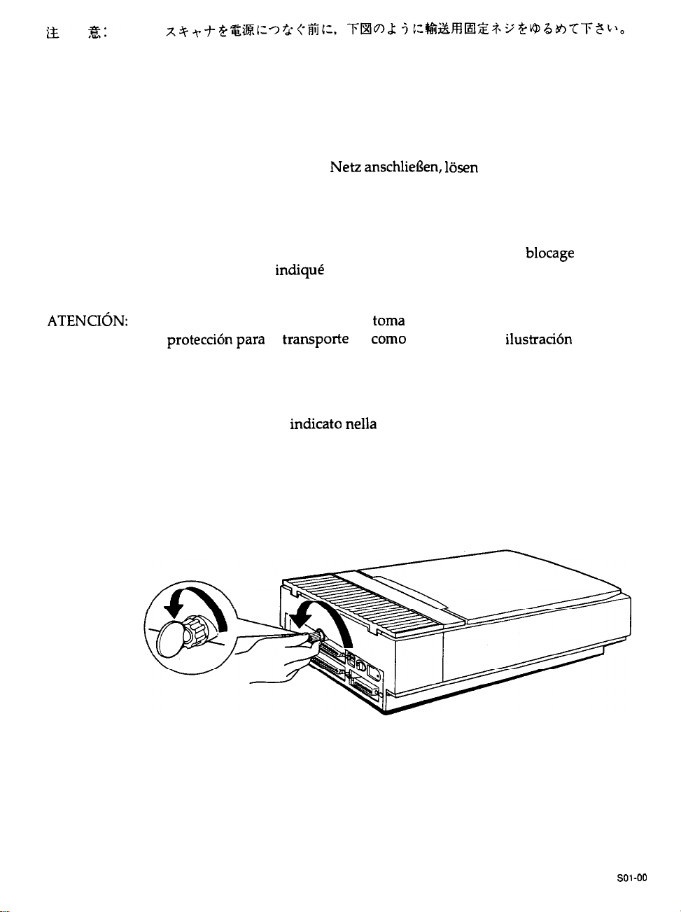
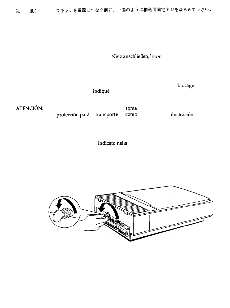
CAUTION:
Before connecting the scanner to a power source, release the transportation
Screw as shown in the figures below.
ACHTUNG:
ATTENTION:
ATENCION:
ATTENZIONE:
Bevor Sie den Scanner ans
Netz
anschlieBen,
l&en
Sie bitte die
Transport-Sicherungsschraube wie in den folgenden Abbildungen
dargestellt.
Avant de connecter le scanner au secteur, retlrez la vis de blocage pour le
transport comme
indique
ci-dessous.
Antes de conectar el scanner a la toma de corriente, afloje el tomillo de
protection
para el
transporte
tal
coma
puede ver en la ilustracion
siguiente.
Prima di collegare lo scanner all’ alimentazione elettrica rimuovere la vite
di bloccaggio come
indicate
nella figura sottostante.
Copyright 0 1994 by Seiko Epson Corporation. Nagano, Japan
Printed in Japan 94.10-.I
4003766
sol-00
Page 3

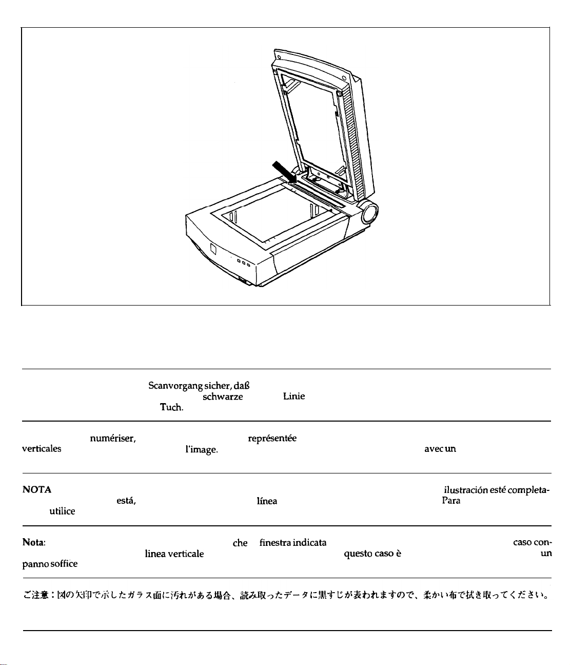
Note: Before scanning, make sure the strip of glass shown in the illustration is completely free of dust or dirt. If it is not, a black
vertical line may appear in the scanned image. If this happens, wipe the glass with a soft, clean cloth.
Hinweis: Stellen Sie vor jedem Scanvorgang sicher,
da auf dem gescannten Bild ansonsten eine schwarze vertikale
daf3
das in der Abbildung markierte Glasfeld absolut sauber und staubfrei ist,
Lit-tie
auftreten kann. Reinigen Sie das Glasfeld in einem solchen
Fall mit einem weichen sauberen Tuch.
Note: Avant de numeriser, assurez-vous que la glace
verticales
noires peuvent apparaitre sur
l’image.
Si des lignes noires apparaissent, nettoyer la glace
rep&en&
sur l’illustration est propre. Si ce n’est pas le cas, des lignes
avec un
NOTA IMPORTANTE: Antes de empezar a explorar, compruebe que la franja de cristal indicada en la
mente limpia. Si no lo
cristal
utilice
un paiio suave y limpio.
Nota:
Prima di effettuare la scansione, assicuratevi
trario potrebbe apparire una
panno
soffice e pulito.
esta,
es posible que aparezca una
linea verticale
nera nell’immagine acquisita. In quest0 case e necessario pulire la finestra con un
the
lfnea
vertical negra en la imagen explorada.
la
fine&a
indicata nell’illustrazione sia perfettamente pulita. In case con-
chiffon doux et propre.
ilustracibn
Para
este completa-
limpiar esa franja de
Page 4

A Note Concerning Responsible Use of Copyrighted Materials
Like photocopiers, scanners can be misused by improper copying of
copyrighted material. Although Section 107 of the U.S. Copyright
Act of 1976 (Title 17, United States Code), the “fair use” doctrine,
permits limited copying in certain circumstances, those
circumstances may not be as broad as some people assume. Unless
you have the advice of a knowledgeable attorney, be responsible
s
and respectful by not
canning published material without the
permission of the copyright holder.
All rights reserved. No part of this publication may be reproduced, stored in a retrieval
system, or transmitted in any form or by any means, electronic, mechanical, photocopying,
recording, or otherwise, without the prior written permission
No patent liability is assumed with respect to the use of the information contained herein.
Neither is any liability assumed for damages resulting from the use of the information
contained herein.
Neither Seiko Epson Corporation nor its affiliates shall be liable to the purchaser of this
product or third parties for damages, losses, costs, or expenses incurred by purchaser or
third parties as a result of: accident, misuse, or abuse of this product or unauthorized
modifications, repairs, or alterations to this product.
Seiko Epson Corporation and its affiliates shah not be liable against any damages or
problems arising from the use of any options or any consumable products other than those
designated as Original EPSON Products or EPSON Approved Products by Seiko Epson
Corporation.
of Seiko Epson Corporation.
EPSON is a registered trademark of Seiko Epson Corporation.
ES-12OOC is a trademark and EPSON Connection is a service mark of Epson America, Inc.
General Notice: Other product names used herein are for identifcation purposes only and may be
trademarks of their respective companies.
Copyright (0 1994 by Seiko Epson Corporation, Nagano, Japan
ii
Page 5
CAUTION:
Before connecting the scanner to a power source, release the transportation
screw as shown in the figures below.
ACHTUNG:
ATTENTION:
ATENCION:
ATTENZIONE:
Bevor Sie den Scanner ans
Netz
anschlieBen,
l&en
Sie bitte die
Transport-Sicherungsschraube wie in den folgenden Abbildungen
dargestellt.
Avant de connecter le scanner au secteur, retlrez la vis de blocage pour le
transport comme
indique
ci-dessous.
Antes de conectar el scanner a la toma de corriente, afloje el tomillo de
protection
para el
transporte
tal
coma
puede ver en la ilustracion
siguiente.
Prima di collegare lo scanner all’ alimentazione elettrica rimuovere la vite
di bloccaggio come
indicate
nella figura sottostante.
Copyright 0 1994 by Seiko Epson Corporation. Nagano, Japan
Printed in Japan 94.10-.I
4003766
sol-00
Page 6
Note: Before scanning, make sure the strip of glass shown in the illustration is completely free of dust or dirt. If it is not, a black
vertical line may appear in the scanned image. If this happens, wipe the glass with a soft, clean cloth.
Hinweis: Stellen Sie vor jedem Scanvorgang sicher,
da auf dem gescannten Bild ansonsten eine schwarze vertikale
daf3
das in der Abbildung markierte Glasfeld absolut sauber und staubfrei ist,
Lit-tie
auftreten kann. Reinigen Sie das Glasfeld in einem solchen
Fall mit einem weichen sauberen Tuch.
Note: Avant de numeriser, assurez-vous que la glace
verticales
noires peuvent apparaitre sur
l’image.
Si des lignes noires apparaissent, nettoyer la glace
rep&en&
sur l’illustration est propre. Si ce n’est pas le cas, des lignes
avec un
NOTA IMPORTANTE: Antes de empezar a explorar, compruebe que la franja de cristal indicada en la
mente limpia. Si no lo
cristal
utilice
un paiio suave y limpio.
Nota:
Prima di effettuare la scansione, assicuratevi
trario potrebbe apparire una
panno
soffice e pulito.
esta,
es posible que aparezca una
linea verticale
nera nell’immagine acquisita. In quest0 case e necessario pulire la finestra con un
the
lfnea
vertical negra en la imagen explorada.
la
fine&a
indicata nell’illustrazione sia perfettamente pulita. In case con-
chiffon doux et propre.
ilustracibn
Para
este completa-
limpiar esa franja de
Page 7

Contents
Options
How to Use This ManuaI
Warnings, Cautions, and Notes
Where United States Users Can Get Help
Chapter 1 Setting Up the Scanner
Choosing a Place for the Scanner
Releasing the Transportation Screw
Plugging in the Scanner
Initialization
Connecting the Scanner to the Computer
SCSI
Installing Scanner Software
................................
......................
..................
.............
CompuServe On-Line Support.
......................
.............................
Computer types
Connecting the parallel interface
..................................
SCSI connections
Terminators
Connecting the SCSI
Power-on sequence
........................
........................
...........................
......................
......................
....................
...............
.................
...............
............
..............
1
2
2
2
3
1-2
1-3
1-4
1-5
1-5
1-6
1-6
1-8
1-8
1-10
1-10
1-12
1-12
111
Page 8

Chapter 2 Scanner Basics
Lights and Buttons
Scanner errors
..........................
..........................
Responsible use of copyrighted materials
Placing a Document on the Scanner
Scanning Large or Thick Documents
Raising the back of the document cover
Using the document shelf
...................
Removing the document cover
Scanner Setting Guidelines
4
Image type or mode
4
Resolution.
d
Size or scale
4
Halftoning and dropout
4
Brightness
4
Color correction
4
Gamma correction
4
Cropping
..........................
..........................
...........................
...........................
Judging Image Quality
Equipment
...............................
RAM and hard disk size
Accelerator boards
Video cards
Monitors
...........................
.............................
File compression software
Maintenance
..............................
.....................
.....................
...................
.......................
......................
........................
....................
.......................
...................
Replacing the fluorescent lamps
Transporting the Scanner
......................
..........
................
................
...........
................
...............
2-2
2-3
2-3
2-3
2-6
2-6
2-7
2-8
2-9
2-9
2-10
2-14
2-15
2-15
2-15
2-15
2-15
2-16
2-16
2-16
2-16
2-17
2-17
2-17
2-18
2-19
2-19
Chapter 3 Troubleshooting
Problems and Solutions
Indicator lights.
iV
.......................
.........................
3-2
3-2
Page 9

Chapter
4 Technical Specifications
Scanner Specifications
Electrical Specifications
Environmental Conditions
Parallel Interface Specifications
Timing charts
SCSI Specifications
Signal pin assignments
Initialization
.............................
.......................................................... 4-4
.....................
..........................
.........................
....................
Appendix
Scanner Functions
How the scanner works
Scanner settings
Glossary
..........................
....................
........................
Index
..................
4-2
4-4
4-5
4-8
4-9
4-10
4-11
A-2
A-2
A-3
Page 10

introduction
The EPSON® ES-12OOC is a true 600 dpi full-color flatbed image
scanner with an A4 size scanning area. It has the ability to scan
in color or gray-scale monochrome, making it ideal for virtually
all uses, from simple drawings to complex full-color
illustrations. It achieves extremely high quality in color by
reading 30 bits per pixel and saving 24 bits per pixel.
Options
The following optional items are available to expand the
versatility of your scanner. For detailed information on the use
of these options, see the guides that come with the options.
Automatic Document Feeder 03813011)
This option is designed primarily for optical character recognition
(OCR) scanning. With software that supports the ES-1200C and
OCR, you can stack up to 30 pages in the automatic document
feeder and scan them automatically. You can then use them in a
word p
rocessing
program just as if you had typed them yourself.
Transparency Unit (B813021)
This option allows you to scan transparent materials, primarily
35mm slides and negatives.
Introduction 1
Page 11
How to Use This Manual
Chapter 1 describes setting up your scanner and connecting it to
your computer. Be sure to read this first. Chapter 2 gives basic
information on using your software and scanner, including
maintenance and transportation Chapter 3 contains
troubleshooting information, and Chapter 4 and the Appendix
provide technical information. See the end of this guide for a
glossary of scanner terms and an index.
Warnings, Cautions, and Notes
Warnings must be followed carefully to avoid bodily injury.
0
Cautions must be observed to avoid damage to your
e
Notes contain important information and useful tips on the operation
of your scanner.
equipment.
Where United States Users Can Get Help
Epson America provides local customer support and service
through a nationwide network of authorized EPSON dealers
and Service Centers.
EPSON also provides the following support services through
the EPSON Connection” at (800) 922-8911:
CI
Assistance in locating your nearest Authorized EPSON
Reseller or Service Center
Q
Technical assistance with the installation, configuration,
and operation of EPSON products
2 Introduction
Page 12

EPSON technical information library fax service
tl
Product literature with technical specifications on our
P
current and new products
Ll
Sales of supplies, parts, documentation, and accessories for
your EPSON product
cl
Customer Relations
CompuServe® On-tine Support
The fastest way to access helpful tips, specifications, drivers,
application notes, and bulletins is through the Epson America
Forum on CompuServe.
If you are not currently a member of CompuServe, you are
eligible for a free introductory membership as an owner of an
EPSON product. This membership entitles you to:
Cl
An introductory $15 credit on CompuServe
P
Your own user ID and password
Q
A complimentary subscription to CompuServe
CompuServe’s monthly publication
To take advantage of this offer, call (800) 848-8199 in the United
States and Canada and ask for representative #529. In other
countries, call (614) 529-1611 or your local CompuServe access
number.
If you are already a CompuServe member, simply type
GO EPSON at the menu prompt to reach the Epson America
Forum.
Magazine,
Introduction 3
Page 13

Important Safety Instructions
Read all of these instructions and save them for later reference. Follow
all warnings and instructions marked on the scanner.
l
Unplug the scanner before cleaning. Clean with a damp cloth only
and do not use liquid or aerosol cleaners. Do not spill liquid on the
scanner.
l Do not place the scanner on an unstable surface or near a radiator or
heat register.
l Do not block or cover the openings in the scanner’s cabinet. Do not
insert objects through the slots.
l Use only the type of power source indicated on the scanner’s label.
l Connect all equipment to properly grounded power outlets. Avoid
using outlets on the same circuit as photocopiers or air control
systems that regularly switch on and off.
l
Do not let the scanner’s power cord become damaged or frayed.
l If you use an extension cord with the scanner, make sure the total
ampere rating of the devices plugged into the extension cord does
not exceed the cord’s ampere rating. Also, make sure the total of all
devices plugged into the wall outlet does not exceed 15 amperes.
l
Except as specifically explained in this User’s Guide, do not attempt
to service the scanner yourself.
l
Unplug the scanner and refer servicing to qualified service personnel
under the following conditions:
If the power cord or plug is damaged; if liquid has entered the
scanner; if the scanner has been dropped or the cabinet damaged;
if the scanner does not operate normally or exhibits a distinct
change in performance. Adjust only those controls that are
covered by the operating instructions.
l
If you plan to use the scanner in Germany, observe the following:
To provide adequate short-circuit protection and over-current
protection for this scanner, the building installation must be
protected by a 16 Amp circuit breaker.
J3eim Anschluf3
sichergestellt werden,
16 A Uberstromschutzschalter abgesichert ist.
des Scanners an die Netzversorgung
da13
die
Gebaudeinstallation
muf3
mit einem
4 Introduction
Page 14

Chapter 1
Setting Up the Scanner
Choosing a Place for the Scanner
Releasing the Transportation Screw
Plugging in the Scanner
Initialization
Connecting the Scanner to the Computer
Computer types
Connecting the parallel interface
SCSI
Installing Scanner Software . . . . . . . . . . . . . . . . . . . .
..................................
SCSI connections
Terminators
Connecting the SCSI.
Power-on sequence
.............................
...........................
......................
........................
........................
.....................
......................
.................
...............
............
..............
1-2
1-3
1-4
1-5
1-5
1-6
1-6
1-8
1-8
1-10
1-10
1-12
1-12
Setting Up the Scanner
1-1
Page 15

Choosing a Place for the Scanner
You should consider the following when selecting a location for
your scanner:
Place the scanner on a flat, horizontal, stable surface. If the
scanner is tilted or at an angle, it cannot operate properly.
Place the scanner close enough to the computer for the
cable to reach.
Allow some space behind the scanner for the cables, and
make sure to place the scanner where you can easily
unplug the power cord. Also allow sufficient space above
the scanner so that you can fully raise the document cover
if necessary.
Keep the scanner away from high temperatures and
humidity and places subject to rapid changes of
temperature and humidity.
Keep the scanner away from direct sunlight and strong
light sources.
Avoid places subject to shocks and vibrations.
1-2
Setting Up the Scanner
Page 16
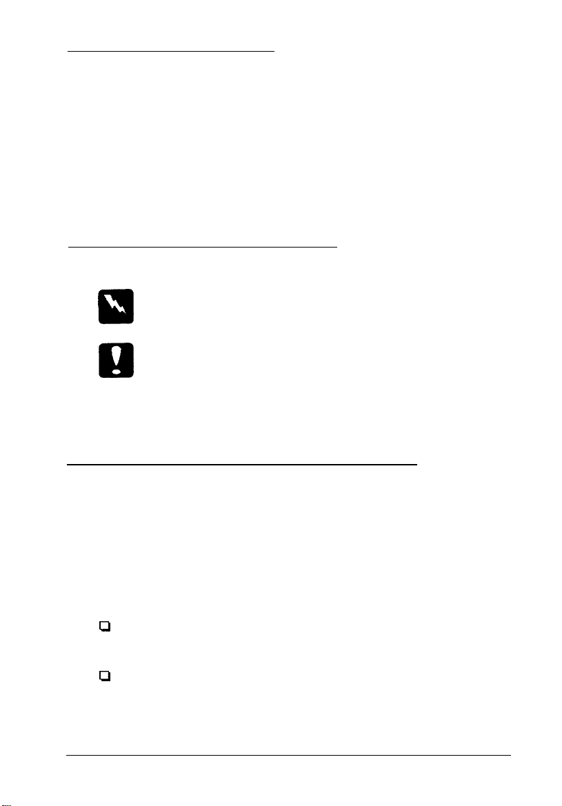
Releasing the Transportation Screw
Before connecting the scanner to a power source, you must
release the transportation screw.
Place the scanner on a flat, stable surface so that its rear
1.
panel is facing you.
Locate the round screw knob in the middle of the rear panel.
2.
Turn the screw counterclockwise as shown by the arrow.
3.
If necessary, turn the screw with a coin. The screw has a
built-in spring, so it pops out a little when it is released.
You cannot remove the screw.
Note:
You will need to screw in the transportation screw when you store or
transport the scanner.
Setting Up the Scanner
1-3
Page 17
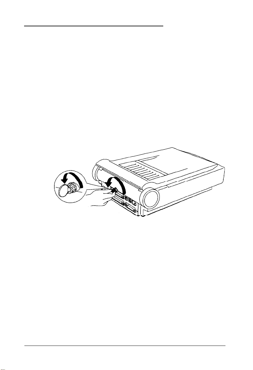
Plugging in the Scanner
1.
Firmly connect the power cable to the power inlet on the
rear
of the scanner and the other end into an appropriately
grounded outlet as shown below.
2.
If any of the scanner’s lamps come on, press the
button to turn the scanner off.
OPERATE
1-4
Warning:
Whenever you turn of the scanner, wait at least 10 seconds
before turning it back on. Rapidly turning it on and off can
damage the scanner.
Setting Up the Scanner
Page 18

In this step you observe the scanner’s self initialization. This
lets you see that the scanner is operating properly before you
connect it to your computer.
1.
Open the document cover so you can see the operation of
the scanner during the initialization.
2. Turn on the scanner by pressing the
When the scanner is initializing, the fluorescent lamps on the
carriage flash and the carriage’s position is reset. If the carriage
is not at the home position (the rear of the scanner), it moves to
the home position.
When the scanner has completed its initialization, the
light comes on. If the scanner does not work as described, turn
it off. Then make sure that you have released the transportation
screw and that the power cord is firmly plugged in and turn it
on again.
If it still does not work as described, see your dealer or call the
EPSON Connection at (800) 922-8911.
OPERATE
button.
READY
Connecting the Scanner to the Computer
Your scanner has both a bidirectional parallel interface and a
SCSI (Small Computer System Interface). You can connect both
of the interface cables to the scanner at the same time. The
scanner switches automatically to the appropriate interface.
Note:
When the scanner is capturing an image, the computer connected to
the other interface cannot use the scanner. When the computer
connected to the parallel interface is turned
not work.
off,
the
RESET
Setting Up the
Scanner
button may
1-5
Page 19

Computer types
0
For a PC-compatible computer, do one of the following:
Install a bi-directional parallel interface board in your
computer. Then connect the computer to the scanner’s
bidirectional interface.
Note:
IBM® PS/2® computers and some other computers have built-in
bi-directional parallel interfaces. You do not need to install one in
those
computers
your printer.
Install a SCSI board in your computer. Then connect the
computer to the scanner’s SCSI interface.
Q
For a Macintosh@ computer you do not need to install a
board in your computer; you just connect your Macintosh
to the scanner’s SCSI interface.
To use an interface correctly, you may need to change settings
on the scanner, computer, or both. The following sections
explain how to set up and connect each type of interface.
unless you need the built-in parallel interface for
Connecting the parrallel interface
Caution:
e
1-6
The scanner’s bi-directional parallel interface requires a
compatible type of interface on your computer. You may not
be able to use the ordinary parallel printer interface on your
computer; check your computer’s specification to see if the
parallel interface is bi-directional.
Setting Up the Scanner
Page 20
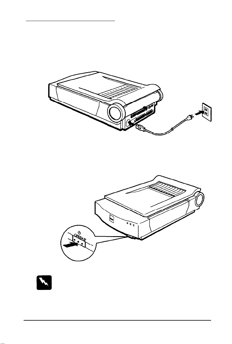
Use a standard shielded parallel interface cable.
1.
Make sure that both the scanner and computer are turned
Off.
2. Connect the 25-pin end of the cable to the computer; then
tighten the screws on the sides of the connector.
3.
Connect the 36-pin end of the cable to the scanner; then
fasten the connector with the clamps on the sides of the
connector.
Setting Up the Scanner
1-7
Page 21

SCSI
For some computers, you first install a SCSI board in your
computer. Then follow the directions below to connect your
scanner and computer. All Macintoshes have SCSI ports; you
do not need to install a SCSI board in the computer. Follow the
directions below to connect the scanner to your Macintosh
SCSI connections
The SCSI interface allows you to connect up to eight devices,
including the computer, in what is called a daisy-chain
arrangement. A daisy chain is made up of a computer and one
or more SCSI devices. Only the first SCSI device is connected to
the computer; each of the other devices is connected to the
previous device.
Each device has a SCSI ID number: the computer is usually
number 7, and each of the other devices must have a different
number between 0 and 6. Also, the first device and the last
device in the chain (not including the computer) must have a
terminator, and no other device can have a terminator. The
SCSI on the scanner has two 50-pin connectors.
If you connect the scanner directly to the computer, you need
a SCSI cable with a 25-pin connector on one end (for the
computer) and a 50-pin connector on the other end (for the
scanner). If you connect the scanner to another SCSI device, use
a SCSI cable with 50-pin connectors on both ends.
1-8
Setting Up
the Scanner
Page 22
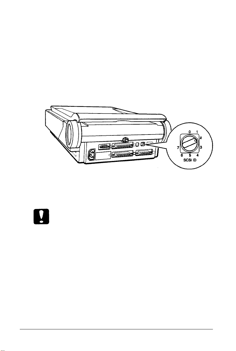
SCSI ID number setting
The factory set SCSI ID of the scanner is 2. The computer is
usually ID number 7. If you are going to add the scanner to a
system in which one of your SCSI devices already has a SCSI
ID of 2, change the ID number of the scanner to an unused
number as described next.
1.
Locate the SCSI ID rotary switch on the rear panel of the
scanner.
2.
To change the SCSI ID, turn the small dial to the desired
number.
Q
Caution:
Do not set the SCSI ID to an ID number that is already
assigned to another device. The computer, scanner,
devices will not function properly.
Setting Up the Scanner
and
other
1-9
Page 23
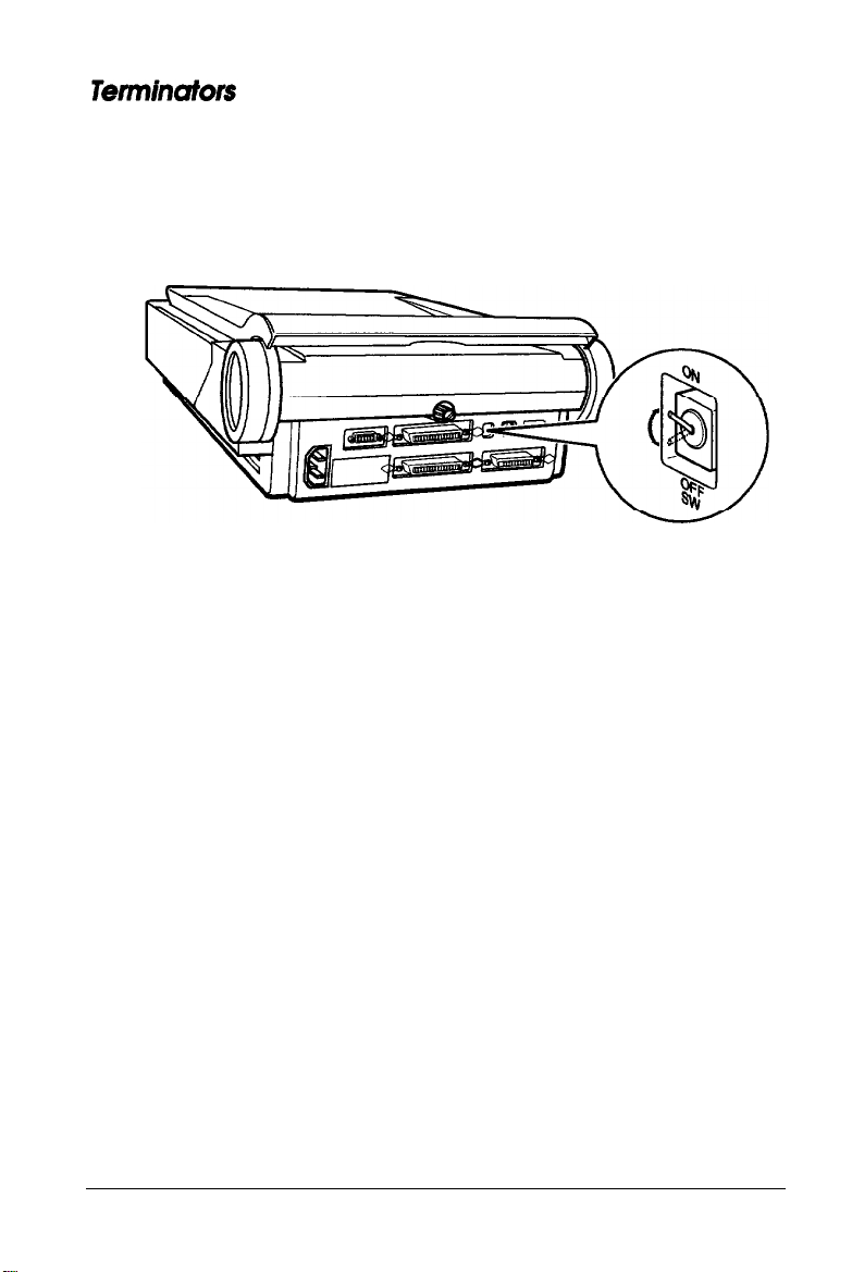
The scanner has a built-in terminator. If the scanner is the only
SCSI device you connect to your computer or if it is the last
device in the daisy chain, leave the internal SCSI terminator
turned on. It is on if the switch is up.
If the scanner is in the middle of a daisy chain, turn the
terminator switch off.
Do not use an external terminator.
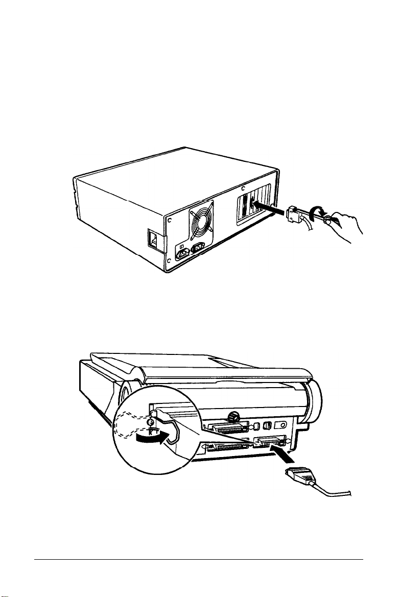
Connecting the SCSI
Connect the scanner with the SCSI as follows:
1.
See that the scanner, the computer, and all other SCSI
devices are turned off and unplugged from the power
source.
1-10
Setting Up the Scanner
Page 24
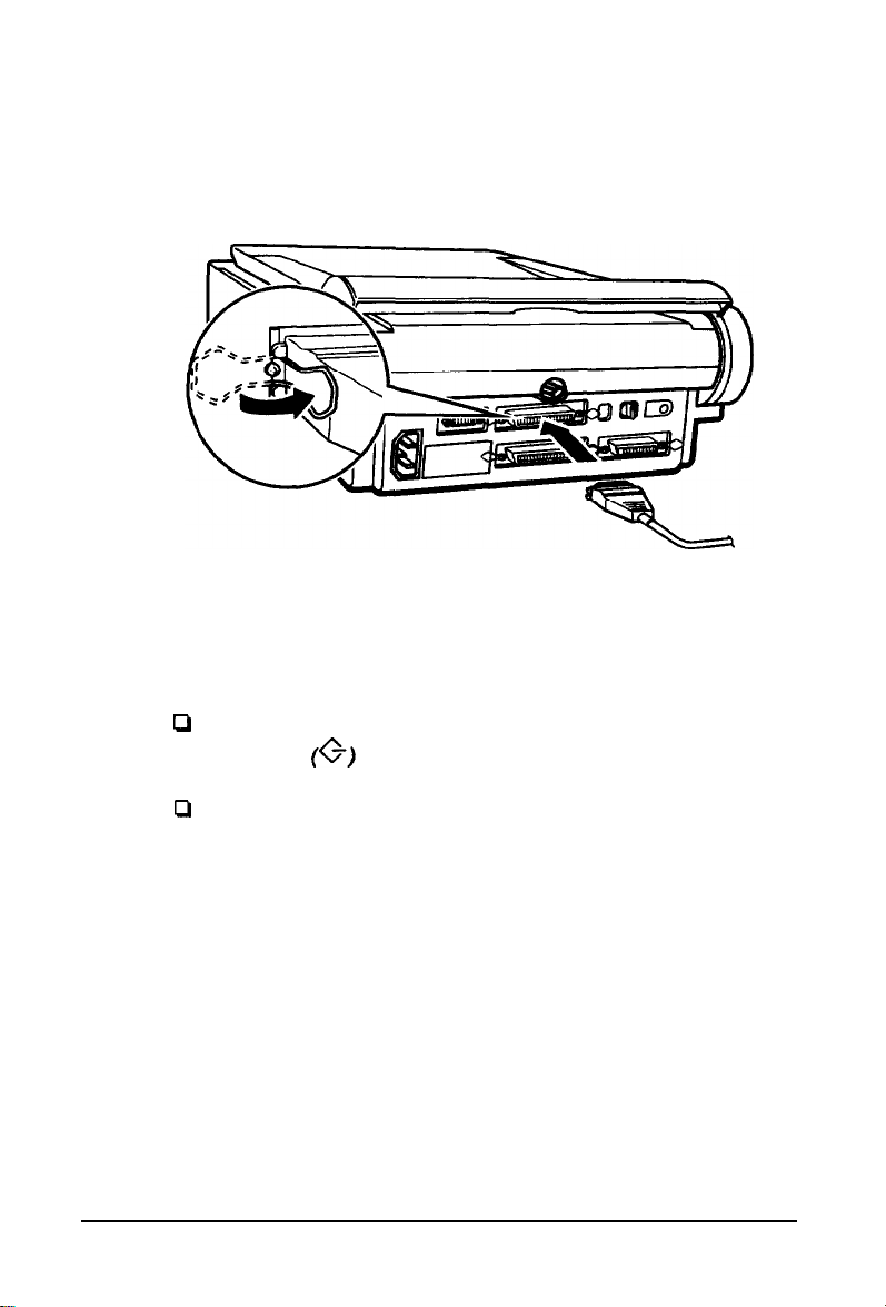
Connect the 50-pin end of the cable to either the top or
2.
bottom SCSI connector of the scanner; then fasten the
connector with the clamps on the sides of the connector, as
shown.
Connect the other end of the cable to the SCSI port of your
3.
computer or the other SCSI device.
Notes:
LI
The SCSI port of
SCSI icon
$3)
the
Macintosh is the larger port with the
over it.
CL
If you are connecting the scanner to a SCSI device other than
the computer, use a cable with 5O-pin connectors on both
ends.
The connection is now complete. Connect the power cables.
4.
Always turn on the scanner and other external SCSI devices
5.
before you turn on your computer.
Setting
Up
the Scanner
1-11
Page 25

Power-on sequence
Follow these instructions for the power-on sequence each time
you turn your computer and SCSI devices on.
If you have an internal hard disk, turn on the scanner and any
other SCSI devices you plan to use. Wait a few seconds; then
turn on the computer.
If you have an external hard disk, turn on the scanner, external
hard disk (first on the daisy chain), and any other SCSI devices
you plan to use. Wait a few seconds; then turn on the computer.
SCSI devices in the middle of the daisy chain may be left off if
you don’t plan to use them.
Installing Scanner Software
Now that you have connected the scanner to your computer,
the next thing to do is install your scanner software. Follow the
instructions in the user’s manual for the software. Then read
Chapter 2, “Scanner Basics,” before your first scan
1-12
Setting Up the Scanner
Page 26
Chapter 2
Scanner Basics
Lights and Buttons
Scanner errors
Responsible use of copyrighted materials
Placing a Document on the Scanner
Scanning Large or Thick Documents
Raising the back of the document cover.
Using the document shelf
Removing the document cover
Scanner Setting Guidelines
4
Image type or mode
J
Resolution
d
Size or scale
4 Halftoning and dropout
4
Brightness
4 Color correction
4
Gamma correction
4
Cropping.
Judging Image Quality
Equipment
RAM and hard disk size
Accelerator boards
Video cards
Monitors.
File compression software
..............................
.........................
.........................
................
...................
................
.....................
....................
..........................
.........................
..................
..........................
.......................
.....................
..........................
.......................
....................
.......................
...........................
............................
..................
.........
...............
..........
2-2
2-3
2-3
2-3
2-6
2-6
2-7
2-8
2-9
2-9
2-10
2-14
2-15
2-15
2-15
2-15
2-15
2-16
2-16
2-16
2-16
2-17
2-17
2-17
Maintenance
Replacing the fluorescent lamps
Transporting the Scanner
.............................
......................
...............
Scanner Basics 2-1
2-18
2-19
2-19
Page 27
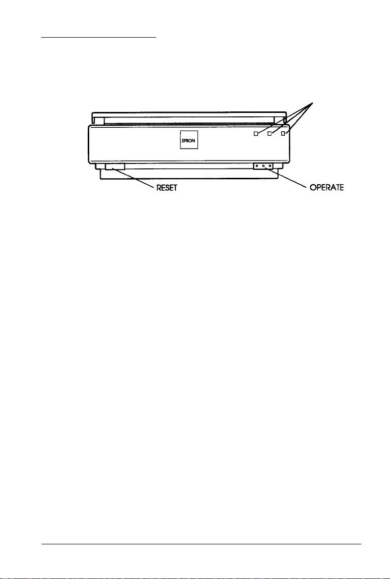
Lights and Buttons
The scanner has three indicator lights and two buttons.
lights
button
OPERATE
button
light (green)
Comes on when the scanner is turned on.
READY
light (green)
Comes on when the scanner is ready to scan images. This light
flickers during scanning. When an error occurs, it and the
ERROR
ERROR
Indicates when an error occurs. Along
light indicate the type of error.
light (red)
with the READY
light, it
indicates the type of error.
OPERATE
button
Turns the scanner on and off.
RESET
button
Resets the scanner after an error occurs. Pressing this button
during scanning stops the scanner and may cause an error in
the scanning software. This button may not work if two
computers are connected to the scanner, and the computer with
the bi-directional parallel interface is not turned on.
2-2 Scanner Basics
Page 28
Scanner errors
If an error occurs, the scanner stops operating and the
and
ERROR
details.
lights show the type of error. See Chapter 3 for
Responsible use of copyrighted materials
Remember to respect the rights of copyright owners. Don’t
scan published text or images without first checking the
copyright status.
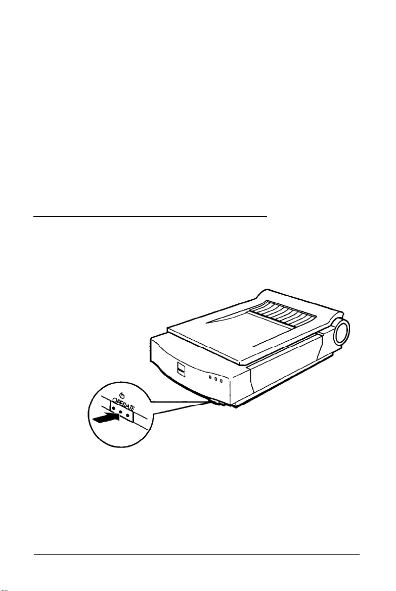
Placing a Document on the Scanner
1.
Turn on the scanner by pressing the
The
OPERATE
light comes on.
OPERATE
button.
READY
Scanner Basics 2-3
Page 29
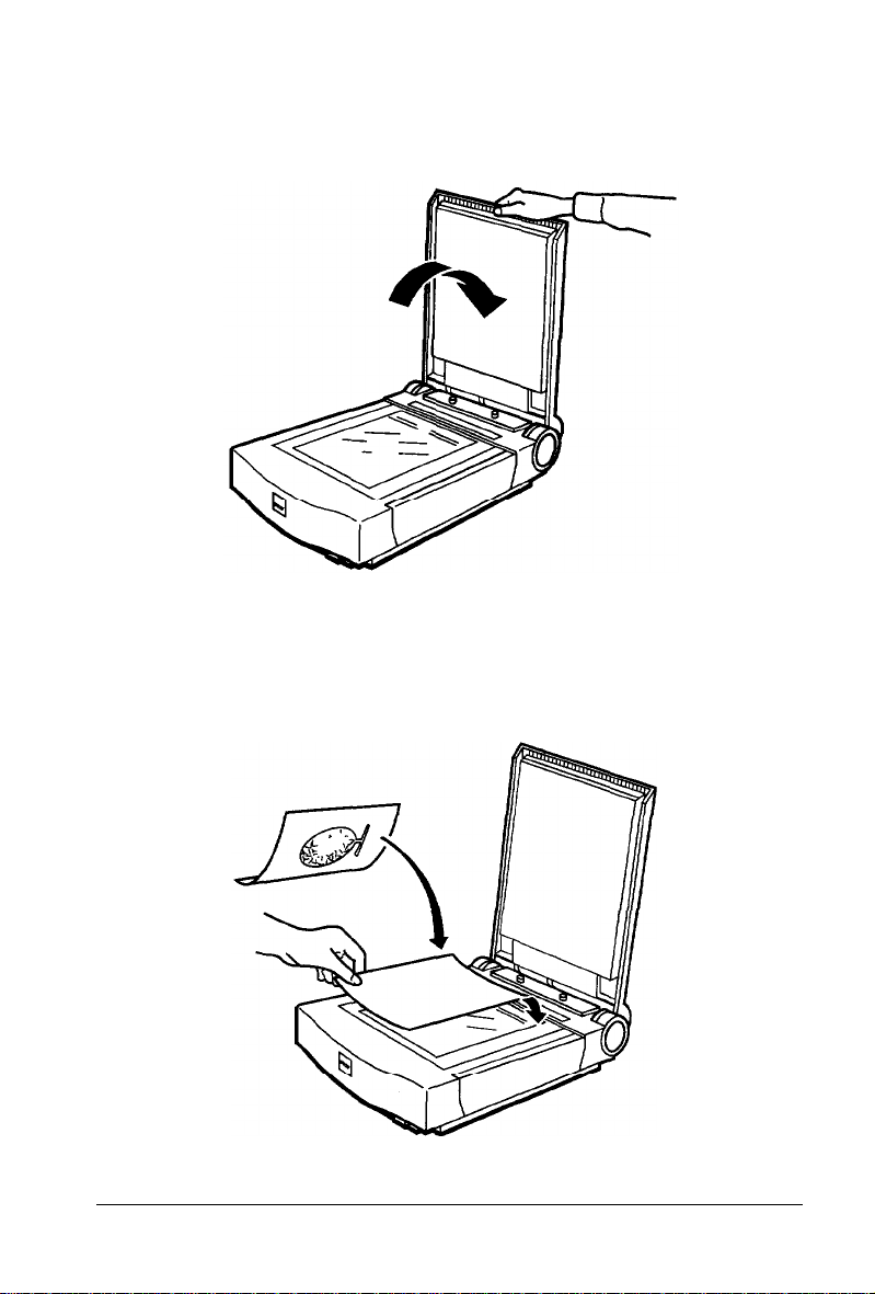
Turn on the computer and see that the scanner’s
2.
light has come on. Open the document cover.
Place the document on the document table, with the side to
3.
be scanned down. Make sure that the document is carefully
aligned.
READY
2-4 Scanner Basics
Page 30

4. Close the document cover gently so that the aligned
document is not moved.
Note:
Make sure that the document is flat against the glass surface so
that the image is properly focused. Also make sure to close the
document cover. This prevents interference from external light.
Always keep the document table clean. See “Maintenance” later
in this chapter for information on cleaning the scanner.
Avoid twisting the document cover when you open or close it.
Do not leave photographs on the document table for an extended
period of time; they may stick to the glass.
Do not place heavy objects on top of the scanner.
5. Start the scanner software on the computer, and follow its
procedures to scan the image.
Scanner Basics 2-5
Page 31

Scanning Large or Thick Documents
Your scanner has three ways you can adjust it so that you can
scan large or thick documents or other materials.
Raising the back of the document cover
For thick documents or other materials, you can raise the back
of the document cover, as shown below. Then close the cover
and scan.
2-6 Scanner Basics
Page 32

Using the document shelf
For wide documents or other materials, you can lift the
document shelf into place as shown below.
After you have finished using the document shelf, push in on
the support of the shelf, as shown below. Then return the shelf
to its former position.
Scanner Basics 2-7
Page 33

Removing the document cover
For especially difficult documents or other materials, you
can completely remove the document cover. Just raise it
completely; then pull it off in the direction of the arrows in
the illustration below.
Reattach the document cover reversing the procedure above.
Be sure to hold the cover in a vertical position as you slip its
attachments into place.
2-8 Scanner Basics
Page 34

Scanner Setting Guidelines
This overview of scanner settings will give you a little
background for using your scanning software. The messages
on the screen and your software manual should be your main
guide to scanning, but this section can supplement your
understanding of your software’s on-screen menus.
Each 4 icon indicates a setting that you make or check. The first
two are the most important.
Note:
Your software may use a somewhat different order or slightly different
terminology.
4
lmage type or mode
For the best and most efficient scans, you need to know which
type of images you are scanning: drawings, black and white
photographs, or color photographs. The corresponding terms
used by scanning software are
Line art
This is the setting for drawings, including all drawings or
pictures made up of black and white only, with no gray tones,
such as the ones below.
line art, gray scale,
and
color.
Scanner Basics 2-9
Page 35

Gray
scale
(also
called monochrome or
This is the setting for black and white photographs and
drawings with various shades of gray in addition to black and
white. You can also use this setting for color photographs that
will be printed in black and white.
color
This is the setting for color photographs or other originals in
color.
Note:
Scans from photographs are better than scans from published images,
such as newspaper or magazine pictures, because
conflicts.
experimenting with your scanner.
4
Resolution
The best resolution setting depends on the image type or mode
(line art, gray scale, or color)
“Printing methods” and “File size” below; then use the table on
page 2-13 to find the resolution you should use.
Use
photographs instead of published images for
and
continuous tone
of
half toning
the printing method. Read
Printing of display methods
The best resolution to use depends on what type of output or
printing method you will be using. The usual printing methods
for scanned images fall into the following categories.
Q
2-10
Black and white printers
good to excellent for text and line art but are not as good
for gray-scale images. These printers can be used for
reproducing photographs in documents like newsletters
that do not require the highest quality.
Scanner Basics
(laser, inkjet, or dot matrix) are
Page 36

The examples below show the typical quality of
photographs printed on laser printers. Laser printers
with a resolution of 600 dpi produce much better results
for photographs than 300 dpi laser printers, as you can
see below.
300 dpi
6OOdpi
Scanner Basics 2-11
Page 37

D
Electronic color printers use laser, ink jet, or other
technologies to produce color or gray scale images that
range from coarsely patterned to nearly photographic
(often called continuous tone) quality. It is best to see
samples from a color printer before you decide to use it.
These printers are usually used for small quantities of color
images or for preliminary proofs of images that will be
printed on a printing press.
Li
Printing presses are for high quality and high volume work.
You scan and edit your images and then send the files to a
service bureau or printing company, which uses high
resolution phototypesetters (also called imagesetters) for
high quality text and gray-scale images. For full-color
images, you scan in color and then use your image editing
software to manipulate the image and produce color
separation files. If you plan to do this, see the guidelines
below on resolution and then follow the instructions in
your software manual for making separations. Your service
bureau or printing company should also provide helpful
information.
ci
Computer screens require lower resolutions than most
printers. If your scanned image will be viewed only on a
computer monitor or screen and will never be printed,
you can use lower scanning resolutions for top-quality
work. Remember that the scanner can read and save up to
16 million colors. If your computer can display only 16 or
256 colors, you will not be able to see all of the quality of
the scanned image.
File size
In gray scale and color, use the lowest resolution that gives
acceptable quality for your printing or display method because
high resolutions mean large files. An A4 or letter-size full-color
scan at 300 dpi uses as much as 25 megabytes (MB) of disk
space.
2-12 Scanner Basics
Page 38

Large files use up your computer and hard disk memory; they
take longer to process, to print, or to transmit by modem; and
they are more difficult to save to a disk for sending to a service
bureau or printing company.
Many printing methods cannot use all of the information
stored in a high-resolution scan, so in these cases part of the
information is wasted.
Resolution guidelines
This table shows the recommended resolutions in dots per inch
or pixels per inch for the image types and printing or display
methods just described. Also, you may want to experiment
with your scanner settings, possibly using a cropped version of
your image to save time, until you achieve the desired results.
The resolution that you use to scan an image (input resolution)
does not have to match the dots per inch of your printer
(output resolution). Input and output resolution are two quite
different measurements. Just follow the guidelines below.
Resolution guidelines
Scanner Basics 2-13
Page 39

Here’s how to calculate more precisely the required resolution for
gray scale or color on an electronic color printer or a printing press:
1.
Find out the
the measurement of resolution for high quality image
printing. Do not confuse it with dots per inch, which is not
an equivalent measurement.
2.
Multiply the lines per inch by two to find the best scanning
resolution For example, for 175 lines per inch (a common
resolution for magazines and books), scan your image at
350 dpi (2 x 175 = 350).
For even smaller file sizes, try scanning at about 1.5 times the lines
per inch This may cause little or no perceptible loss of output quality.
Note:
For color or gray scale images, ignore the dpi (dots per inch) of your
printing device. Even though your service bureau may use an
imagesetter with a 2400 dpi resolution, a scan resolution of only 150
to 350 dpi will produce the highest quality gray-scale or color images
the imagesetter can print. Similarly, even though your laser printer
may have a 300 dpi resolution, a scan resolution
give the best quality gray scale images it can print.
lines per inch
of the printing method. This is
of
only 80 to 120 dpi
4
Size or scale
This is usually expressed as a percentage. If you want your
printed image to be larger than the original, increase its size
with this setting. If you are not sure how large you want the
printed image, choose the
reduce the image size later with your software. (You can also
increase the size with your software, but you may lose some
quality.)
Note:
The size of the image on your monitor will probably be different from
the size
2-14 Scanner Basics
of
the image when you print it.
largest size you might use. You can
Page 40

4
Halftoning and dropout
For nearly all uses,
you have special needs that require halftoning at the time of
scanning, see the Appendix for technical information on
halftoning, dithering, and dropout.
d
Brightness
The minus numbers lighten the image, the plus numbers
darken the image. To lighten a dark original use -1 to -3, or to
darken a light original use +l to +3. Usually you should leave
this setting at zero.
4
Color correction
Use the default or CRT display.
4
Gamma
Use the default or CRT Display B.
Note:
Your software may have different settings for Brightness, Color
correction, and Gamma correction.
correction
none is
the best setting for these. In case
J Cropping
If you know you are going to use only part of an original, use
your software’s cropping tools before you scan (if possible) to
select only the part of the image that you will use. This will
make your image file smaller.
Scanner Basics 2-15
Page 41

Judging lmage Quality
When you look at your monitor to evaluate a scanned image,
remember that the image will look different when it is printed.
A monitor is a comparatively low-resolution device; some
images that look good on a monitor do not look as good when
printed and vice versa. Keep in mind the final output device as
you choose settings and manipulate the image.
In addition, each output device may produce different results.
A proof printed on an electronic color printer will look
different from the same image printed on a printing press.
Equipment
Your present equipment may be sufficient for your scanning
needs, but if you are not satisified with the quality of the
images on your monitor or with the speed of image processing,
read this section While it does not contain specific
recommendations, it describes various possibilities for
improving your scanning system. For further information, see
your dealer or an experienced scanner user.
RAM and hard disk size
Scanned images can use much more memory than text files, so
you may need more Random Access Memory (RAM) in your
computer and a larger hard disk than you have used
previously.
Accelerator boards
In addition to memory, processing speed is important because
large files take longer to process than small ones. Therefore,
you may want to add an accelerator board to your computer.
2-16 Scanner Basics
Page 42

video cards
A video card that is sufficient for text may not be good enough
for displaying graphic images, especially in color. If all your
scanned images look coarse on your monitor, you may want to
upgrade your video card. You will need 24-bit color, also called
true color or millions of colors, for the best display of images.
The resolution of your monitor, of course, also affects the
quality of the image you see. Consider a high resolution
monitor if you do precise color work, but first be sure you have
the right video card.
File compression software
Many different programs are available to make image files
smaller for storage or transmission. For example, they can
enable you to store a 3MB image file on a floppy disk. Some
compression software can compress images and restore them
with no loss of data or quality; others compress images more,
but the restored file is not exactly the same as the original. The
difference between the original and restored files is, however,
not always noticeable.
Scanner Basics 2-17
Page 43

Maintenance
To keep your scanner operating at its best, you should clean it
periodically. Before cleaning, unplug the power cable.
Clean the outer case with mild detergent dissolved in water.
If the glass of the document table gets dirty, clean it with a soft
dry cloth. If the glass is stained with grease or other hard-toremove material, use a small amount of glass cleaner on a soft
cloth to remove it. Wipe off any remaining liquid with a dry
cloth.
Be sure that there is no dust on the glass of the document table.
Dust can cause white spots in your scanned image.
Warning:
Be careful not to get water on the scanner mechanism or
electrical components.
Caution:
Do not scratch or damage the glass
do not use a hard or abrasive brush to clean it. A damaged
glass surface can decrease the scanning quality.
of
the document table, and
Never use alcohol, thinner or corrosive solvent to clean the
scanner. These chemicals can damage
as well as the case.
Be careful not to spill liquid into the scanner mechanism or
electronic components. This could permanently damage the
mechanism and circuitry.
Do not spray lubricants inside the scanner.
Never open the scanner case.
2-18 Scanner Basics
the
scanner components
Page 44

Replacing the fluorescent lamps
The luminosity of the fluorescent lamps declines over time. If
the lamps break or become too dim to operate normally, the
scanner stops working and both the
ERROR
must be replaced. For details, contact your dealer.
0
light flash. When this happens, the lamp assembly
Warning:
Never open the case of the scanner. If you think repairs or
adjustments are necessary, consult your dealer.
READY
light and the
Transporting the Scanner
When you transport the scanner a long distance or store it for
an extended period, follow the steps below to secure the
carriage.
1.
Turn on the scanner and wait until the carriage moves to the
home position (the back of the scanner). Then turn off the
scanner.
2. Push in the transportation screw and turn it clockwise to
secure the carriage.
Scanner Basics 2-19
Page 45

Note:
If the scanner is broken, the carriage may not automatically
the home position. If fit does not, raise the front
it up until the carriage comes
perform Step 2 above.
to
rest
at the back of
of the
the scanner. Then
return
scanner and hold
to
2-20 Scanner Basics
Page 46

Chapter 3
Troubleshooting
Problems and Solutions
Indicator lights
.........................
.......................
3-2
3-2
Troubleshooting 3-1
Page 47

Problems and Solutions
The problems you may have while using the scanner
often
involve the operation of your software and computer. Problems
fall in the following major categories:
U
Incorrect setup of the interface
U
Inappropriate selection of the scanner functions
P
Incorrect setup of your computer or software
Q
Incorrect operation of your software.
Also see the documentation that came with your software,
computer, and printer for possible solutions.
Indicator lights
If an error occurs, the scanner stops operating and the
and
ERROR lights show the type
Error type
Command error
Interface error
Fatal error
Option error
READY
I On
Off
Flashing Flashing
off
of error.
ERROR
I On
Flashing
Off
READY
Command error
The scanner has received incorrect commands from your
scanning software.
When this error occurs, try the scanning operation with your
software over again The scanner returns to normal when it
receives correct commands. Normally you do not need to reset
the scanner.
3-2 Troubleshooting
Page 48

lnterface error
The interface setup is wrong, or the scanner is not properly
connected to the computer.
When this error occurs, check the interface connection Then
push the
RESET
button or turn the scanner off and then back on
to reset it.
Fatal error
This indicates one of the following problems:
One or more fluorescent lamps needs to be replaced.
The transportation screw is not released.
The scanner is broken.
There is a problem, such as an open cover, with the
optional transparency unit or the optional automatic
document feeder.
Check that the transportation screw is released and check any
options installed; then push the
RESET
button. If the scanner
still does not operate properly, try turning the scanner off and
then back on. If the scanner still does not operate properly, or if
this error occurs repeatedly, consult your dealer.
Option error
This indicates a problem such as a paper jam with an installed
option unit.
Check the option unit and correct the cause of the trouble.
Troubleshooting 3-3
Page 49

The OPERATE OPERATE
light does not come on.
Make sure the power cable is correctly plugged into the
scanner and the power outlet.
The READY READY
light does not come on.
Make sure the scanner is correctly connected to the computer
and that the computer is turned on.
The scanner does not start scanning.
See that the
scanner’s
READY light
is on.
Make sure that you have selected the correct interface port and
settings with your software. Also make sure the interface board
on your computer is properly installed.
If you are connecting the scanner with the SCSI interface, see
that the terminator and SCSI ID are correctly set up.
If you have other expansion boards in your computer, see that
they are not interfering with the interrupt setting of the
interface board for your scanner. (See your computer manual.)
3-4 Troubleshooting
Page 50

The scanner software does not work properly.
Be sure you have correctly installed your software.
Check that the system requirements, such as the operating
system version, are correct for using your software.
See if the computer has enough memory for your software. If
you are running other software at the same time, using RAM
resident programs, or have many device drivers, the computer
may not have enough memory remaining. (gee your software
and computer manuals.)
Make sure that your software supports this model of scanner
and that you correctly installed or set up the software. (gee
your software manuals.)
The entire image is distorted or blurred.
Make sure that the document is placed flat against the
document table (the glass area).
You may have accidentally moved the document during
scanning. Check the position of the document and do not move
it while the scanner is operating.
See that the scanner is not tilted or placed on an unstable
surface.
Troubleshooting 3-5
Page 51

Part of the image is distorted or blurred.
Part of the document may be wrinkled, warped, or not in
contact with the document table (the glass area). Be sure the
document is uniformly flat.
Caution:
Do not place heavy objects on the document table.
e
The edges of the document are not scanned.
The document table has non-readable areas around the edges.
Adjust your document’s position so that the image comes
inside the readable area.
Color is patchy or distorted at the edges of the document.
If the document is very thick or warped at the edges, the edges
of the image may be colored. Cover the edges of the document
with opaque paper to avoid having outside light interfere.
If part of the document is outside the document table, the edge
may not be in contact with the document table and may be
discolored. Change the position of the document.
3-6 Troubleshooting
Page 52

The image is
faint or out of focus.
Check that the document is placed flush against the document
table.
Check your gamma correction setting. If it is set for printer, the
image looks lighter when displayed on a monitor.
Make the brightness setting darker.
The image is too dark.
Adjust the brightness with your software. Also check the
brightness and contrast values of your display screen.
Straight lines in the image are jagged.
The document may be placed at an angle on the document
table. Align it so that the horizontal and vertical lines are
carefully aligned with the scales on the top and side of the
document table.
Troubleshooting 3-7
Page 53

The image does not look the same as the original.
Try different settings and combinations of the scanner
functions.
Check that your software is correctly installed. Check the
capability of your software and computer. (gee your software
and computer manuals.)
If you are importing an image file into your application
software, see if the file format is acceptable for your software.
Also check that the settings of your application and your image
match (See your software manual.)
A line of dots is always missing on the scanned image.
If this happens on your printed image only, your printer or its
print head is probably malfunctioning. (gee your printer
manual.)
If this happens on both your screen and printout, the scanner’s
sensor may be malfunctioning. Consult your dealer.
When halftoning is used, textured patterns composed of a series of
dots appear on particular areas of an image.
This is normal. See the Appendix for examples of halftoning.
3-8 Troubleshooting
Page 54

The color on the display seems different from that of the original
image.
Check the settings of the scanner functions, especially data
format (bits/pixel/color), gamma correction, and color
correction. Try a different combination of these settings.
Check the capability of your computer, display adapter, and
software. Some computers can change the color palette to
adjust colors on your screen. (gee your computer manual.)
Exact matching of colors is very difficult. Check the manuals
for your software and your monitor for information on color
matching and calibration.
The printed color seems different from that of the originals.
Exact reproduction of colors is very difficult. See your software
manual or your printing company for guidance on color
matching.
The printed image is larger or smaller than the original size.
Check the image size settings in your software. Do not use the
size of the image on your monitor to judge the printed size.
Troubleshooting 3-9
Page 55

The image cannot be printed on the printer, the printout is
garbled, or the printout is not an image.
Check that the printer is properly connected with the computer
and is correctly set up. (See your printer manual.)
Check that your software is properly installed and set up for
your printer. (See your software manual.)
3-10 Troubleshooting
Page 56

Chapter 4
Technical Specifications
Scanner Specifications
Electrical Specifications
Environmental Conditions
Parallel Interface Specifications
Timing charts
SCSI Specifications
Signal pin assignments
Initialization . . . . . . . . . . . . . . . . . . . . . . . . . . . . 4-11
.......................
.......................
.....................
..................
..........................
.........................
....................
4-2
4-4
4-4
4-5
4-8
4-9
4-10
Technical Specifications 4-1
Page 57

Scanner Specifications
Scanner type:
Photoelectric device:
Effective pixels:
Maximum document
size:
Scanning resolution:
Output resolution:
Color separation:
Reading sequence:
Flatbed, color /monochrome
CCD line sensor
5096 dots by 7016 dots at 600 dpi, 100%
216 mm by 297 mm
(8.5
inches by 11.7 inches)
US letter size or A4
600 dpi
50,60,72,75,80,90,100,120,133,144,
150,160,175,180,200,216,240,300,320,
360,400,480,600,800,900,1200,1600,
1800, and 2400 dpi.
Values above 600 through software
interpolation.
By switching light sources (G, R, B)
Monochrome mode:
One-pass scanning (Dropout color
selectable from Green, Red or Blue.)
Color page sequence mode:
Three-pass scanning (G, R, B)
Color line sequence mode:
One-pass scanning (G, R, B)
size:
Image data:
Brightness:
4-2 Technical Specifications
50% to 200% in 1% steps.
10 bits per pixel per color saved as 8 bits
per pixel per color maximum
7
levels
Page 58

Maximum reading in
pixels:
16128 (main scan)
Halftoning process:
Gamma correction:
Color correction:
Interface:
Light source:
Reliability:
Enable/disable selectable.
3 halftoning modes (A, B, and C) and
4 dither patterns (A, B, C, and D) for
bi-level data
(Halftoning mode A only in color line
sequence mode)
(2 downloadable dither patterns)
2 for CRT display
3 for printer
1 for user defined
1 type for CRT display
3 types for printer output, available in
color line sequence mode only
1 type for user defined
Bi-directional parallel and SCSI
Noble gas fluorescent lamps
Main unit MCBF: 100,000 cycles of carriage
movements
Dimensions and
weight:
Width:
Depth:
Height:
Weight:
383 mm (15 inches)
595 mm (24 inches)
170 mm (7 inches)
about 12 kg (26 lb)
Technical Specifications
4-3
Page 59

Eletrical Specifications
120
Rated voltage:
Rated frequency:
VAC or 220 to 240 VAC
50
to6OHz
Power consumption:
Insulation resistance:
Approx. 45 W
10
MC2
between AC power line and chassis
at5OOVDC
Environmental Conditions
Temperature:
Humidity:
Operating conditions:
Note:
Specifications are subject to change without notice.
Operation: 40” F to 95” F (5” C to 35” C)
Storage: -13” F to 140” F (-25” C to 60” C)
Operation: 10% to
condensation
Storage: 10% to 85%, without condensation
Ordinary office or home conditions.
Extreme dust should be avoided.
Operation under direct sunlight
or near a strong light
avoided.
80%,
source
without
should be
4-4 Technical Specifications
Page 60

Parallel lnterface Specifications
lntefface type:
Data format:
Synchronization:
Handshaking:
Logic level:
Connector type:
Connector pin arrangement:
18
Bi-directional parallel interface
8-bit parallel
By external strobe pulse
By ACKNLG and BUSY signals
Input/output data and interface control
signals are TTL level compatible
36-pin Centronics® type connector
1
Technical Specifications 4-5
Page 61

Signal pin
assignments
Pin
No.
1
2
3
4
5
6
7
8
9
10
11
R&urn
pin
19
m
21
22
23
24
25
26
27
28
29
Slgnal
STROBE
DATA0
DATA1 IN/OUT
DATA2
DATA3
DATA4
DATA5
DATA6
DATA7
ACKNLG
BUSY OUT/(IN)
Dlrectlan Function
INAOUT)
IN/OUT
IN/OUT
IN/OUT
IN/OUT
IN/OUT
IN/OUT
IN/OUT
OUT/ON)
STROBE pulse to read In
or send
width must be more
than 0.5 microseconds
at the
terminal.
These slgnals represent
information of bits 1 to 8
respectively. Each signal
Is at a high level when
data is logical 1 and low
when it Is
About a
Low indicates that data
has been
that the scanner is ready
to accept more data.
When this signal is hlgh,
the scanner cannot
receive data. The signal
is high:
2) during scanning
3) when the scanner
not ready
4) when the scanner has
an error
Out
data. Pulse
receiving
loglcal
0.
12-microsecond
1)
during data entry
pulse.
received
and
is
12-15
16
17
18
-
-
-
-
NC
GND
C-GND
NC
4-6 Technical Specifications
-
-
-
-
Not used
Logical ground level
Scanner chassis ground
Not used
Page 62

Slgnal pln assignments (continued)
Pin ROtUfIl
Pin ROtUfIl
No. pin
No. pin
19-30
19-30
-
-
Signal
-
DIrectIon
-
F
31
-
INIT
IN
Function
Twisted pair return signal
ground level
When this signal level
becomes low. the
scanner ls reset to the
state when power Is
turned on. This level is
usually High. The pulse
width
must be more
than 50 microseconds
the receiving terminal.
a?
32
33
34-35
36
Q
-
-
-
-
“Return” denotes the twisted-pair return, to be connected
NC
GND
NC
DIR
-
-
-
IN
Not used
Twlsted pair return slgnal
ground level
Not used
Low indicates the
direction is input.
at signal ground level. For interface wiring, be sure to use
a twisted-pair cable for each signal, and to complete the
connection on the return side. These cables should be
shielded and the ground connected to the chassis of the
host computer and the scanner.
Ll
All interface conditions are based on TTL level.
Technical Specifications 4-7
Page 63

The figures below show the timing for the b&directional
parallel interface as viewed from the scanner.
OUT (from scanner to computer)
STROBE
ACKNLG (I)
STROBE
ACKNLG
(0)
BUSY (I)
DATA (I)
DIR
(0)
JN
(from computer to scanner)
(0)
BUSY (I)
(I)
DATA
(I)
mln 0.5
><
l.JSh
1
mln 0.5
IJS
p
DIR
(0)
4-8 Technical Specifications
min
0.5
PS,
Page 64

SCSI Specifications
lnterface type:
Function:
Logic level:
Electrical standard:
ANSI X3.131-1986 standard
The following functions are included.
BUS FREE phase
ARBITRATION phase
SELECTION/RESELECTION phase
COMMAND phase
(Logical Unit number is fixed to 0 and
command link function is not supported.)
DATA phase
Data in phase
Data out phase
STATUS phase
MESSAGE phase
MESSAGE IN phase
MESSAGE OUT phase
ATTENTION condition
RESET condition
TTL level compatible
As per ANSI X3.131-1986
ID Setting:
Selectable from 0 to 7 and 9 with the rotary
switch (8 should not be selected, and 9 is
for the
Connector
type:
Two 50-pin connectors
Connector pin arrangement:
25
50
ES-300CW
Technical Specifications 4-9
emulation mode.)
1
26
Page 65

Signal pin assignments
In this table, the direction of the signals is given relative to the
scanner.
1 Fin
Signal
GND
I/O
-
I----
1
NC
DB3
DB4
DB5
I/O
I/O
I/O
I/O 29
I/O
I/O
No. I
1-12
14-25
35-37
39-40
42
13
26
27
28
30
31
Descrlptlotl
Ground
Not connected
Data bus 0
Data bus 1
1 DotabusP
Data
bus
3
Data
bus 4
Data
bus 5
I
MSG
SEL
C/D
0
I/O
0
4-10 Technical Specifications
46
47
48
49
50
Message
Select
Control/Data
1
Request
I
Input/Output
I
I
Page 66

Initialization
The scanner can be initialized (returned to a fixed set of
conditions) in three ways.
Hardware initialization:
Cl
When the power is turned on.
Q
When the scanner receives an INIT signal at the parallel
interface (pin 31 goes low).
Q
When the scanner receives a SCSI Reset signal at the SCSI
interface.
Software initialization:
Q
When the software command ESC @ (initialize the scanner)
is received.
CI
When the SCSI Bus Device Message is received.
Technical Specifications 4-11
Page 67

Chapter 5
Saving and Exporting Images
You can always scan an image using your TWAIN-compliant
image editing application. However, if your application is not
TWAIN-compliant, you can use EPSON Scan! II to scan the
image and export it in a format your application can open, as
described in this chapter.
Saving a Scanned Image
before you export an image, you need to save it in its original
EPSON Scan! II format. Otherwise, you will not be able to
retrieve it again in EPSON Scan! II. Follow these steps:
1.
Start EPSON Scan! II, if necessary.
2.
Select Acquire
3.
Select
Scan to scan your image.
from the File menu.
4. Choose
dialog box:
File
Name:
rlzll
Save
AS from the File menu. You see the following
Rlrectorles:
c3epscan2
i
D&es:
EC:
dlskl~vdl
Saving
and
Exporting Images
1
Cancel
1
5-1
Page 68

5.
Choose the drive and directory where you want to save the
image.
6.
Type a filename for your image in the
sure to use the file extension .ORG.
7. Choose OK.
The image is saved in the EPSON Scan! II file format. You can
now open this file and export it with a different format, as
described below.
File Name
field. Make
Exporting an Image
EPSON Scan! II allows you to export an image in a file format
your application software can use. For information on file
formats your software can open, see your software manual.
Note
Your application software
Scan! Zlfilejimnat and EPSON Scan! ZZ cannot open an exported
imagefile. Always save an image in EPSON Scan! II before exporting.
cannot
open images saved in the EPSON
Follow these steps to export an image:
1.
5-2
Choose
dialog box:
Saving and Exporting Images
Export
from the File menu. You see the following
Page 69

2.
Choose the drive and directory where you want to save the
image.
3. Type a filename for your image in the
4. You can choose one of
menu: DIB, TIFF5.0, TIFF6.O(JPEG), JPEG, and EPSF. (For a
description of these file formats, see the Term Glossary.)
Note:
You can select TIFF6.0(JPEG) and JPEG formats only if you
selected
Image Type dialog box when you scanned the image.
5. If you selected the TIFF6.0(JPEG) or JPEG format, EPSON
Scan! II allows you to choose the image quality. Since JPEG
uses a Lossy compression scheme, selecting higher quality
gives you less compression. To choose the image quality,
move the
6. Choose OK.
The image is saved in the selected file format. You can now
import this file into your application software; see your
software manual for instructions.
16 Million Colors for
Quality
these
formats from the File Format
the Pixel Depth
slide bar to
the
File Name
setting
desired setting.
field.
in the
Acquiring and Exporting an Image
EPSON Scan! II allows you to scan and export an image
directly into a selected file format, without displaying it on the
screen. Since the image is not displayed, you can perform
scanning operations more quickly.
Note:
EPSON Scan! II cannot open an image file once it is exported.
Saving and Exporting Images
5-3
Page 70

Follow these steps:
1.
Start EPSON Scan! II, if necessary.
2.
Choose Acquire and Export from the File menu. You see
the TWAIN screen. (If you see the easy screen, click
Advanced.)
3.
Choose Scan. You see the following dialog box:
I
ccl
tl I
Rlrectorles:
ciepeccan2
0 epscm2
I
M
JPEG formats only if you
for the Pixel Depth setting in the
Rle &me:
4.
Choose the directory and drive where you want to save the
exported image.
5. Type a filename for your image in the File Name field.
6.
You can choose one of these formats from the File Format
menu: DIB, TIFF5.0, TIFF6.O(JPEG), JPEG, and EPSF. (For a
description of these file formats, see the Term Glossary.)
Note:
You
can select
selected
Image Type dialog box when you scanned the image.
TIFF6.0(JPEG) and
16 Million Colors
5-4
Saving and Exporting Images
Page 71

7.
If you selected the TIFF6.0(JPEG) or JPEG format, EPSON
Scan! II allows you to choose the image quality. Since JPEG
is a Lossy compression scheme, selecting higher quality
gives you less compression. To choose the image quality,
move the
8. Choose OK.
The image is scanned and exported in the selected file format.
You can now import this file into your application software;
see your software manual for instructions.
Quality
slide bar to the desired setting.
Exiting EPSON Scan! II
To exit EPSON Scan! II, make sure you have saved or exported
your image file. Then choose Exit from the File menu.
Saving and Exporting Images
5-5
Page 72

Appendix
Scanner Functions
How the scanner worksr....................
Scanner settings
..........................
........................
A-2
A-2
A-3
A
Appendix A-l
Page 73

Scanner Functions
Various image processing functions are built into your scanner.
They are briefly described in Chapter 2. This Appendix
contains fuIler, more technical, information All functions must
be controlled from the scanner software, and most functions
can be combined with others to produce a variety of effects.
Note:
Because allfunctions must be wntrolled$!om scanner
all the scannerfunctions may be available, or the range
may be limited. The software may Perprm unique processes on the
image data and the results can be
manual. When using application
details.
dijkrentfiom
soware,
see its documentation for
sofware,
of
those described in this
not
the settings
How the scanner works
The image is divided into a two-dimensional matrix of tiny
elements. Each element is called a pixel, or picture element. The
sensor on the carriage scans a line of pixels, and as the carriage
moves, the succeeding lines of pixels are scanned.
The values of the electrical current for pixels are then processed
and converted into binary data that can be used by computer
devices.
Images such as photographs contain various, almost infinite,
tones between black and white as well as various colors.
These are detected as varied intensities of reflection In
monochrome reading, the scanner converts the intensities
into the tonal data for each pixel. In color reading, the scanner
separates the various colors into three primary colors-green,
red, and blue-and converts the tones of these colors for each
pixel. By this method, the scanner can read any colors within
the image.
A-2 Appendix
Page 74

The data produced by the scanner needs to be reproduced to be
seen as an image. This is done, for example, by displaying the
image data on a computer screen or printing it on a printer. The
same image data can appear different depending on how it is
reproduced. The various scanner functions aid in providing
optimum reproduction results by adjusting the way the image
is captured and converted into image data.
Scanner settings
The table below summarizes the scanner functions and the
settings available on your scanner. Each of them is explained in
the following pages. All of these functions are controlled by the
software commands from your scanner software.
Funciian Avciilable
Resolution
size
Data format
Color mode
Brightness
Halftoning
Gamma correction 5 sefflnas for output devices plus 1 user-defined
Color correctlon
mode
29 settings from 50 to 2400 dpi
5O%to2CXXat
1 to 8
Captures up to 10 bits/pixel/color. When lt captures
over 8 bits, it converts the information to 8
blts/pbel/color.
Color line sequence mode, color page sequence
mode and monochrome mode (dropout color
selectable)
7 levels
3 modes and disabled
4
dither
4 settings for output devices plus 1 user-defined
wfflngs
l%step
bits/plxel/cobr
patterns
You may need to do some trials by yourself to find out your
preferred settings because the original images and the output
methods you use can vary greatly.
Appendix A-3
Page 75

The output resolution determines how many pixels are used
for scanning and reproducing an image. Resolution is
measured in units of dpi (dots per inch), spi (samples per inch),
or ppi (pixels per inch). (AU are equivalent units of measure.)
As the resolution value increases, the image is read and
reproduced in finer detail. At 600 dpi, for example, an image of
one square inch is represented by 360,000 dots.
The 29 resolution settings allow you to choose the best
resolution for most types of printers. The settings available are
50,60,72,75,80,90,100,120,133,144,150,160,175,180,200,
216,240,300,320,360,400,480,600,800,900,1200,1600,1800,
and
2400
dpi. To find a matching resolution for your particular
output device, follow the guidelines in Chapter 2.
Size of scale
The size or scale function allows you to reduce or enlarge the
size of the output image. The value can be set in the range of
50%
to 200% in increments of 1%.
When the size is set to lOO%, the image is scanned at the actual
size for the current resolution. The size values determine the
vertical and horizontal lengths of the image. When the size is
set to 200% the image is enlarged four times the original size.
When the size is set to 50%, the image size is reduced to one
fourth of the original size.
The size function affects the number of dots scanned. An image
scanned at 180 dpi and 200% has the same number of dots as
an image scanned at 360 dpi and 100%.
To enlarge or reduce the image size, use the scanner’s size
function through your software at the time of scanning. Avoid
increasing the image size after scanning because the image
quality deteriorates. The default size value is 100%.
A-4 Appendix
Page 76

Data fomat
The data format specifies the number of bits used to represent
the tone of a pixel. The data format can be set in the range of
1 bit to 8 bits per pixel per color.
As the value increases, more tones and colors can be captured
in the scanned image. In monochrome, 1 bit/pixel
data) can represent only two levels of tones, black (0) or white
(1). With 2 bits/pixel (quad-level data), four levels of tones can
be represented by the binary values of 00,
91,lO
8 bits/pixel corresponds to 256 shades of gray, producing near
photographic quality results.
In color, the data format defines tones for each of the three
primary colors of green, red, and blue. One bit/pixel/color can
represent eight colors (2 x 2 x
2),
and 2 bits/pixel/color can
represent 64 colors (4 x 4 x 4). Eight bits/pixel/color (total
24
bits for a pixel) can represent over 16 million colors.
The scanner can read up to 10 bits/pixel/color. Above
8 bits/pixel/color the scanner converts the image data to
8 bits/pixel/color and sends it to the computer. This gives
much higher quality.
@-level
and 11. Using
Data
formal
1
bit/pixel/color
2
blts/plxel/color
3
bits/pixel/color
4
blts/plxel/color
5
bits/pixel/color
6
blts/plxel/color
7
bits/pixel/color
8
bits/pixel/color
Monochrome
2
grays
4
grays
8
grays
16 grays
32 grays
64
grays
128
grays
256 grays
1
color
8 colors
64 colors
512 colors
4,096 colors
32,768 colors
262,144 colors
2D97.152
16.777.216 colors
colors
Appendix A-5
Page 77

8
bits
2
bits
1 bit
To reproduce an image of more than 2 bits/pixel/color the
output device should be capable of producing the same tones.
Many displays and printers cannot do this and are limited to
monochrome without gradations, or to 8 or 16 or 256 colors.
The data format chosen also affects the amount of data
necessary for scanning and storing an image. The larger the bits
per pixel value chosen, the larger the amount of image data
becomes.
One of seven brightness levels can be chosen for scanning.
Medium is the normal setting.
A-6 Appendix
Page 78

It is better to use darker settings for line art, or faint original
images, and to use lighter settings for darker original images.
The brightness can be combined with any other function.
The graph below shows the differences between the brightness
settings when the gamma correction is set for the CRT Display
A setting.
Data
Darker Y
Ughtestl
=tiing
image input
Normal (center)
Lighter
Darkest
setting
Appendix A-7
Page 79

Color mode
The color mode specifies color reading or monochrome
reading. In color reading, you can choose either page sequence
reading or line sequence reading. In monochrome reading a
dropout color can be specified (green, red, or blue).
Color page sequence reading
The scanner scans the document three times (one each for
green, red, and blue), and produces three pages of image
data that combine to give full color image data. Since the
image data can be divided into three sets, a computer with
limited memory or processing speed can handle it more
easily.
Color line sequence reading
The scanner scans the document with one pass of the
carriage, reading green, red, and blue for every line. This
yields more accurate color separation. Because the color for
each pixel can be determined as soon as it is read, the color
correction function can be used.
Monochrome reading
(staruiard)
The scanner scans the document with one pass and reads
the image in monochrome (black and white). In standard
monochrome, the scanner
Gminates
the document with
the green, red, and blue lights all at once so that minimum
dropout color results.
Dropout colors (monochrome reading only)
The dropout color is the color you tell the scanner not to
read. You can choose a dropout color from green, red or
blue. Use a dropout color when you do not want to read
one of these colors-for example, when scanning an image
on a colored background.
The default color mode is standard monochrome.
A-8 Appendix
Page 80

Halftoning is a process of changing an image to a pattern of
dots. This is required because a printing press produces images
in a different way than photography does.
Photographs have an almost infinite number of tones, with an
almost infinite number of colors for color photographs, but
printing uses only individual single-color dots. Black and white
images use black dots, and color images use only four colors of
dots: cyan (blue-green), magenta, yellow, and black. The size
and spacing of these dots is varied to simulate photographic
continuous tones. In some halftoning the dots are quite
noticeable, as you can see in one of the illustrations on
page 2-11 of this manual. If the dots are fine enough, however,
the printed image appears to have continuous tones, as you can
see on the cover of this manual.
You can choose various types of halftoning at the time you
scan, but it is nearly always best to choose the halftoning
setting “off” or “none” and have the halftoning done by the
image editing software or by the output device (such as a laser
printer). The illustrations on page 2-11 were scanned in gray
scale with no halftoning and printed on a black and white laser
printer. The printer performed the halftoning so that it could
print the image.
You will always get better results scanning from a photograph
than from a printed image, such as a picture in a newspaper or
magazine, because printed images have already been halftoned
and you may see a conflict in the halftone methods.
Appendix A-9
Page 81

You can select from three types of halftoning, as well as enable
or disable the halftoning process itself. When halftoning is
disabled, the tones that the data can represent are determined
by the data format. Halftoning is not available when 3
bits/pixel/color or more are selected as the data format, since
halftoning is not necessary for such data. Halftoning modes B
and C are not available with color line sequence reading.
Your scanner also provides four typical dither patterns for l- or
2-bits/pixel/color data format. With suitable software, you can
define two more dither patterns.
Note:
Usually your scanner software or printing method can
halftoning. Therefore, you should usually
patterns when you scan.
0
Halfloning mode A
This is the standard halftoning mode. The image is
converted into a hard tone to produce a distinct image, and
is suitable for most purposes. (1 and 2 bits/pixel/color)
not
use
pe+rm the
haljbning
or dither
Q Hdjloning
With this mode, the image is converted into a softer tone.
This mode is suited for images which contain large areas of
similar tones. (1 bit/pixel/color)
0 Halftoning molie
With this mode, the image is represented in a way similar
to the screen commonly used for newspaper photographs.
The gradations of the tones are represented by clusters of
different numbers of dots. (1 bit/pixel/color)
A-10 Appendix
mode
B
C
Page 82

Halftoning mode A
Haljbning mode B
Halfoning
mode
C
NOW
Dither pattern A
Halftone is expressed in 4 by 4 bayer dither pattern.
Dither pattern B
Halftone is expressed in 4 by 4 spiral pattern.
Dither pattern C
Halftone is expressed in 4 by 4 net screen dither pattern.
Dither pattern D
Halftone is expressed in 8 by 4 net screen dither pattern.
Appendix A-11
Page 83

Dither pattern A
Dither pattern B
Dither pattern C Dither pattern D
Note:
Changing the size
of
a halftone-processed image with your application
software may &grade the image. Instead use the scanner’s size or
scalefunction at the time ofscanning to select your desired image size.
A-12 Appendix
Page 84

This function adjusts the light intensity ratio between the
original image and the output data. It brings out more detail in
areas of both highlight and shadow. When the image is
reproduced on certain types of output devices, the tones of the
image will be closer to those of the original. The term “gamma”
(y)
means the shape and slant of the line on the graph that
shows the ratio, as shown below
Lighter
CRT Display A
CRT Display B
I
Data
Printer Output A
Printer Output B
Printer Output C
Darker
-
Lighter
Image input
Gamma correction provides five settings, and can be combined
with all other scanner functions. Choose an appropriate setting
from the five modes below.
P
CRT Display A
The output data is in proportion to the original image, as
shown in the above graph. This setting is suited for most
types of computer displays which can display an image in
l-bit/pixel/color format. This mode is also suited for
images without continuous tones, such as line art (y = 1).
Appendix A-13
Page 85

CRT Display B
This setting is suited for analog-input CRT displays which
can display an image with multiple levels of tones of more
than 1 bit/pixel/color (y = 1.8). This is usually the best
setting.
Printer Output A
This setting is suitable for highdensity printers, such as
24-dot printers and some page printers. The image is
converted into a lighter image to compensate for the higher
(darker) density of such printers. The image looks faint
when viewed on a CRT display.
Printer Output B
This setting is suitable for low-density printers, such as
8-dot (9-pin) printers, and page printers. The image is
converted into a slightly darker image to compensate for
the lower (lighter) density of such printers. The image looks
faint when viewed on a CRT display.
Printer Output C
This setting is suitable for high contrast printing of images
which contain both picture and text. This setting gives
higher contrast and more definition than either Printer
Output A or B. The dark and light parts of images are
accentuated by this method.
Color of correction
Color correction is functional only with color line sequence
mode, because the color of a pixel is immediately determined
when the pixel is scanned. Color correction provides four
settings. To disable this function, simply choose color page
sequence reading or monochrome reading.
This function processes the image data so that the data will be
most suited for the characteristics of the color output device
used.
A-14 Appendix
Page 86

P
CRT displays
This setting compensates colors for the characteristics of
color CRT displays.
CI
Impact dot-matrix printers
This setting compensates colors for the characteristics of
impact dot-matrix color printers.
Q
Thermal transfer printers
This setting compensates colors for the characteristics of
thermal transfer color printers.
Q
Ink jet printers
This setting compensates colors for the characteristics of ink
jet color printers.
Appendix A-15
Page 87

Glossary
addtive primary colors
Primary colors which produce white when mixed in a certain
proportion. These are red, green and blue--the colors of the
scanner lamps and color monitor displays.
bi-level data
Image data which is composed of 1 bit/pixel. A pixel is
represented by a single bit of digital data that can express only
1 (light) or 0 (dark).
bit
Short for binary digit. The smallest unit of data in computer
processing. A bit can represent two values, on and off, or 1
and 0.
bit/pixel
The unit to indicate the number of bits allocated for a pixel. The
larger the value, the more detail of a pixel is represented.
brightness
A scanner function to lighten or darken the output image data.
A unit of information consisting of eight bits. A byte can
represent a control code or character.
A component of the scanner which contains the optical sensor
and light source for scanning.
Glossary GL-1
Page 88

color correction
A method of adjusting the color image data for a particular
type of device so that the reproduction results become close to
the original colors.
color separation
A process to convert full-color images into a limited number of
primary colors. The additive primary colors (red, green, and
blue) are used by the scanner and the subtractive primary
colors (cyan, magenta, and yellow) plus black are used for
printing press separations.
A set of values used when no other selections have been made.
dithering
A process in which software or an output device simulates
continuous tones with groups of dots.
document
The physical item, such as a sheet of paper or a book, that you
place on the document table for the scanner to read.
Short for dots per inch. A unit of measurement for resolution.
The higher the value, the higher the resolution.
dropout color
A color you set the scanner not to recognize.
GL-2 Glossary
Page 89

ESC/I
Abbreviation for EPSON Standard Code for Image scanners. A
system of commands to control image scanners with software.
ESC/P
Abbreviation for EPSON Standard Code for Printers. A system
of commands to control printers with software.
gamma correction
A method of adjusting the gamma curve so that the
reproduction results on different types of output devices have
gradations similar to the original image.
gamma curve
The graph that shows the contrast ratio between the input
(original image) and output (image data) in image processing.
halftoning
A data processing method of converting continuous tones into
patterns of dots so that the output data simulates the tones.
home position
The position at the back of the scanner where its carriage rests
before a scanning operation.
A device that uses computer files to produce high-resolution
text and graphics output on film or paper. These are usually
found in service bureaus and printing companies.
Glossary GL-3
Page 90

A printer that transfers ink onto the paper by striking the inked
ribbon with a number of small pins.
A printer that transfers ink onto the paper by spraying it
through a number of small nozzles.
A piece of hardware, a method, or a standard used for
connection between or among computer devices.
A type of color scanning that separates primary colors line by
line. The carriage makes only one pass.
Black and white images, or images represented only by the
intensity of luminosity.
The type of color scanning in which the entire image is scanned
once for each separation color.
Short for picture element. Each image is composed of a number
of pixels. Pixels are also counted in units of dots.
plain bi-level
Bi-level image data without the halftoning process.
GL-4 Glossary
Page 91

An interface channel through which data is transmitted
between devices.
primary colors
Basic colors. See additive primaries and subtractive primaries.
resolution
Indication of how finely an image is resolved into pixels.
Measured in dots per inch (dpi), or pixels per inch (ppi), or
samples per inch (spi).
scan
An operation performed by the sensor and the carriage. The
image is divided into pixels by scanning.
scanning area
The physical size of the image that can be scanned by the
scanner.
subtractive primary colors
Primary colors that produce black when mixed in certain
proportion. These are cyan magenta, and yellow. In printing,
black is often added to give more definition because mixing of
actual inks cannot produce pure black.
A value that is referenced to determine whether a certain value
is larger or smaller. The scanner uses a number of thresholds to
convert an image into digital data.
Glossary GL-5
Page 92

lndex
A
Accelerator board, 2-16
Art, line, 2-9, 2-13
Automatic document feeder, 1
B
Bi-directional interface, 2, 1-5-7
Bits/pixel/color, 3-9, A-5-6
Black and white
images, 2-9-11
printer, 2-10-11
Board
accelerator, 2-16
expansion, 3-4
interface, 1-5-7
video, 2-17
Brightness, 2-15, 3-7, A-6-7
Button
OPERATE, 1-4, 2-2, 3-4
BESET, 2-2, 3-3
C
Cable
interface, 1-7, 1-8, 1-11
power, 4, 1-4
Card, video, 2-17
Carriage, 1-5
Chain, daisy, 1-8, 1-10, 1-12
Choosing a place, 1-2
Cleaning
document table, 2-18
scanner, 2-18
Color, 2-10, 2-13--14, A-2, A-8
Color correction, 2-15, A-14-15
Color printing, 2-16, 3-9
Color separation, 2-12
Colors, number of, A-5-7
Compression, file, 2-17
Computer, connecting to, 1-5-12
Continuous tone, 2-10, 2-12
Contrast, 3-7
Cord, power, 4, 1-4
Correction
color, 2-15, A-14-15
gamma, 2-15, 3-7, A-13-14
Cover, document, 1-5, 2-4-5
Cropping, 2-15
D
Daisy chain, 1-8, 1-10, 1-12
Darkness, 2-15, 3-7, A-6-7
Data format, 3-8, 3-9, A-5-6
Dimensions, 4-3
Disk, hard, 1-12, 2-13, 2-16
Display, 2-15-17
Distortion, image, 3-5-7
Dithering, A-10-12
Document
cover, 1-5, 2-4-5
placement, 2-4-5
table, 2-5, 2-18
Dot matrix, 2-10
Dots per inch, 2-13, 2-14
Dpi, 2-14
Drawings, 2-9-10
Dropout color, 2-15, A-8
Index IN-1
Page 93

E
Electrical, 4-4
Electronic color printers, 2-12,
2-13
Environmental conditions, 4-4
Equipment, 2-16-17
ERROR light, 2-2, 2-19, 3-2
Expansion board, 3-4
F
File compression, 2-17
File size, 2-12-13, 2-16
Fluorescent lamps, 1-5, 2-19, 4-3
Focus, 2-5, 3-7
Format, data, 3-8, A-5-7
Images
continuous tone, 2-10, 2-12
gray scale, 2-10, A-5-7
printed, 2-9-11
Imagesetter, 2-12, 2-13-14
Initialization, 1-5, 4-11
Ink jet, 2-10
Interface
parallel, 1-5--7, 4-5, 4-8
SCSI, 1-8, 1-11,4-9
Interface cable, 1-5--7
J
Jagged lines, 3-7
G
Gamma correction, 2-15, 3-7,
A-13-14
Gray scale, 2-10, 2-13, A-5-7
Guidelines, resolution, 2-13-14
H
Halftoning, 2-15, 3-8, A-9-12
Hard disk, 1-12, 2-13, 2-16
Help, 2
Home position, 1-5, 2-19-20
Humidity, 1-2,4-4
I
IBM PS/2, 1-6
Image distortion, 3-5-7
Image type, 2-9-10
Lamps, 1-5, 2-19, 4-3
Laser, 2-10-12
Light
ERROR, 2-2, 2-19, 3-2
READY, 1-5, 2-2, 2-19, 3-2, 3-4
Lightness, 3-7, A-6--7
Line
art, 2-9, 2-10, 2-13
screen, 2-14
sequence mode, A-8, A-10,
A-13
Lines, jagged, 3-7
Lines per inch, 2-14
Location, scanner, 1-2
Lpi, 2-14
M
Macintosh SCSI port, 1-8
Maintenance, 2-18-19
Memory, 2-13, 3-5
IN-2 Index
Page 94

Method, printing, 2-1--12
Mode, image type, 2-9-10
Monitor, 2-14, 2-16, 2-17
Monochrome, 2-10, A-2, A-8
N
Newsletters, 2-10
0
OPERATE button, 1-4, 1-5, 2-2
Optical Character Recognition
(ORC), 1
Options, 1
Output resolution, 4-2
P
Page sequence, 4-2, A-8
Parallel interface, 2, 1-5-7, 4-5
4-8
Photographs, 2-5, 2-9--11, A-9
Phototypesetter, 2-12
Pin connections, 4-5, 4-10
Pixels, 4-3, A-2, A-4
Placement
document, 2-4-5
scanner, 1-2
Plugging in, 1-4
Position, home, 1-5, 2-19--20
Power cord, 4, 1-4
Power on sequence, 1-12
Ppi, 2-13, 4-2, A-4
Press, printing, 2-12, 2-13, 2-16
Printed size, 2-14, 4-9
Printer
dot matrix, 2-10, A-14-15
electronic, 2-10-12, A-13-14
laser, 2-10-12
Printing method, 2-10-12
Printing press, 2-12, 2-13, 2-16
Problems and solutions, 3-2-10
Proofs, 2-12, 2-16
PS/2, 1-6
Q
Quality, image, 2-16
R
RAM, 2-16
READY light, 1-5, 2-2, 2-19, 3-2,
3-4
Releasing,
transportation screw, 1-3
Removing
document cover, 2-8
Replacing lamps, 2-19
RESET button, 2-2, 3-3
Resolution, 2-10-12, A-4
guidelines, 2-13-14
output, 4-2, A-4
RGB, 4-2
S
Safety instructions, 4
Scale, 2-14, A-4
Scale, gray, 2-10, 2-14, A-5-7
Scales, document table, 3-7
Screen, line, 2-14
Index IN-3
Page 95

Screw, transportation, 1-3,2-19
SCSI interface, 1-8, 4-9
ID number, 1-9
power on sequence, 1-12
terminator, 1-10
Sequence
line, A-8, A-10, A-14
page, A-8, A-14
power on, 1-12
Service bureau, 2-12
Settings,
2-9-15
Setup, 1-1--5
Size
file, 2-12-13, 2-16
image,
2-14,
A-4
printed, 2-14
Slides, 1
Solutions, 3-2-10
Space, 1-2
Specifications, 4-2--12
Spi (samples per inch), A-4
switch
SCSI ID number, 1-9, 4-9
V
Video card, 2-17
W
Weight, 4-3
Where to get help, 2
T
Table, document, 2-5, 2-18
Technical specifications, 4-2--11
Temperature, 1-2, 4-4
Terminator, 1-10
Timing, interface, 4-8
Tone, continuous, 2-10, 2-12
Transparency unit, 1
Transportation screw, 1-3, 2-19
Transporting scanner, 2-19
Troubleshooting, 3-2-10
Turning on the scanner, 1-4--5
IN-4 Index
Page 96

Epson America, Inc.
20770 Madrona Avenue
Torrance, California 90503
 Loading...