


EQUITYI+
User’s Guide
and
Diagnostics
®
EPSON

®
EPSON
Equity™ I +
User’s Guide
Y14499113001

IMPORTANT NOTICE
DISCLAIMER OF WARRANTY
Seiko Epson Corporation makes no representations or warranties, either express
or implied, by or with respect to anything in this manual, and shall not be liable for
any implied warranties of merchantability and fitness for a particular purpose or
for any indirect, special or consequential damages. Some states do not allow the
exclusion of incidental or consequential damages, so this exclusion may not apply
to you.
COPYRIGHT NOTICE
All rights reserved. No part of this publication may be reproduced, stored in a
retrieval system, or transmitted, in any form or by any means, electronic, mechanical, photocopying, recording or otherwise, without the prior written permission of
Seiko Epson Corporation. No patent liability is assumed with respect to the use of
information contained herein. While every precaution has been taken in the preparation of this publication, Seiko Epson Corporation assumes no responsibility for
errors or omissions. Nor is any liability assumed for damages resulting from the use
of the information contained herein. Further, this publication and features
described herein are subject to change without notice.
TRADEMARKS
Epson is a registered trademark of Seiko Epson Corporation.
Equity is a trademark of Epson America, Inc.
Centronics is a registered trademark of Centronics Data Computer Corp.
Hercules is a trademark of Hercules Computer Technology.
IBM is a registered trademark of International Business Machines Corp.
MS and GW are trademarks of Microsoft Corp.
Copyright 0 1986 by Seiko Epson Corporation
Nagano, Japan
ii

FCC COMPLIANCE STATEMENT
FOR AMERICAN USERS
This equipment generates and uses radio frequency energy and if not installed and
used properly, that is, in strict accordance with the manufacturer’s instructions, may
cause interference to radio and television reception. It has been type tested and found
to comply with the limits for a Class B computing device in accordance with the
rules,
specifications in Subpart J of Part 15 of FCC
which are designed to provide
reasonable protection against such interference in a residential installation. However,
there is no guarantee that interference will not occur in a particular installation. If this
equipment does cause interference to radio or television reception, which can be determined by turning the equipment off and on, the user is encouraged to try to correct
the interference by one or more of the following measures:
l Reorient the receiving antenna
l Relocate the computer with respect to the receiver
l Move the computer away from the receiver
l Plug the computer into a different outlet so that computer and receiver are on
different branch circuits.
If necessary, the user should consult the dealer or an experienced radio/television technician for additional suggestions. The user may find the following booklet prepared by
the Federal Communications Commission helpful:
“Television Interference Handbook”
This booklet is available from the U.S. Government Printing Office, Washington DC
20402. Stock No. 004-000-00450-7.
Note: If the interference stops, it was probably caused by the computer or its periph-
eral devices. To further isolate the problem:
Disconnect the peripheral devices and their input/output cables one at a time.
If the interference stops, it is caused by either the peripheral device or its I/O
cable. These devices usually require shielded I/O cables. For Epson peripheral
devices, you can obtain the proper shielded cable from your dealer. For nonEpson peripheral devices contact the manufacturer or dealer for assistance.
WARNING
This equipment has been certified to comply with the limits for a Class B
computing device, pursuant to Subpart J of Part 15 of FCC Rules. Only
peripherals (computer input/output devices, terminals, printers, etc.) certified to comply with the Class B limits may be attached to this computer.
Operation with non-certified peripherals is likely to result in interference
to radio and TV reception.
The connection of a non-shielded equipment interface cable to this equipment will invalidate the FCC Certification of this device and may cause
interference levels which exceed the limits established by the FCC for this
equipment.
. . .
111

Contents
Introduction
How to Use This Manual
Setting Up Your System
1
Unpacking
Removing the disk drive protector sheet
Choosing a Location
Arranging the Components
The rear panel
The front panel
Connecting the Power Cord
Connecting the Video Monitor
Connecting the Keyboard
Connecting the Printer
Parallel interface
Serial interface
The Equity I+ character set
Setting the DIP Switches
DIP switch set 1 (internal operations)
DIP switch set 2 (parallel and serial
port operations)
Turning On the Computer
Safetyrules..
Initial setup procedure
Initial screen display
..................................
.....................................
................................
................................
.................................
.........................
........................
...........
.............................
.......................
...............................
......................
....................
........................
...........................
...............................
.....................
.........................
..............
.............................
........................
..................
............................
.......
Intro-1
Intro-2
1-1
1-1
1-2
1-2
1-3
1-4
1-5
1-6
1-7
1-8
1-10
1-10
1-12
1-12
1-13
1-14
1-16
1-18
1-18
1-19
1-19
2
Using Your Equity I+
Special Keys
Selecting Execution Speed
Resetting the Computer
Turning Off the Computer
Using Disks and Disk Drives
How disks work
Choosing diskettes for the Equity I+
Caring for your disks and disk drives
Inserting and removing diskettes
Write-protecting diskettes
....................................
.........................
........................
..........................
........................
..
...................
...............................
..............
..............
.................
.......................
2-1
2-1
2-2
2-3
2-4
2-4
2-5
2-5
2-5
2-7
2-8
V

Making backup copies
Using a single floppy disk drive
Using a hard disk drive
..........................
.........................
..................
2-9
2-9
2-10
Installing Option Cards
3
Removing the Cover
Inserting the Option Card
Removing an access slot cover
Replacing the Cover
Post-installation Setup
Removing Option Cards
Troubleshooting
4
The Computer Fails to Start Up
The Video Display Does Not Appear
The Computer Locks Up or Freezes
Floppy Disk Problems
Hard Disk Problems
Software Problems
Printer Problems
Option Card Problems
.............................
.............................
............................
..............................
............................
.............................
...............................
................................
Appendixes
Changing Jumper Settings
A
Jumper J1, Floppy Disk Controller
Jumper J2, Parity RAM
........................
........................
...................
.........................
...................
...............
................
...........................
.....................
..................
...........................
3-1
3-1
3-3
3-5
3-6
3-7
3-7
4-1
4-1
4-1
4-2
4-2
4-3
4-3
4-4
4-4
A-1
A-1
A-3
Specifications
B
Main Unit .....................................
Keyboard
Mass Storage
Power Supply
Environmental Requirements
Physical Characteristics (CPU Only)
Video and Display Options
Glossary..
C
Index
vi
. . . . . . . . . . . . . . . . . . . . . . . . . . . . . . . . . . . . . . . .
.................................
......................................
...................................
...................................
......................
................
.......................
....................................
B-1
B-1
B-2
B-2
B-2
B-2
B-2
B-3
C-1
Index-1

Figures
System arrangement
1-1
1-2
Rear panel
1-3
Front panel
Inserting the power cord
1-4
Connecting the monitor cable
1-5
1-6
Opening the keyboard socket cover
Connecting the cable to the main unit
1-7
Adjusting the keyboard legs
1-8
1-9
Locating the printer
Connecting the printer
1-10
1-11
Location of DIP switches
DIP switch label
1-12
Equity I+ keyboard
2-1
2-2
Speed switch
Inserting diskettes
2-3
Write-protect notch
2-4
Write-protect switch
2-5
3-1
Back panel screws
Side screws under plastic inserts
3-2
Removing cover..
3-3
Inserting option card
3-4
3-5
Removing access slot cover
3-6
Replacing the cover
.....................................
....................................
...................................
.............................
..........................
.............................
...........................
.................................
..............................
...............................
..............................
.............................
...............................
...............................
.............................
..............................
.....................
.................
..............
.......................
....................
...
....................
........................
1-3
1-4
1-5
1-6
1-7
1-8
1-9
1-10
1-11
1-12
1-13
1-14
2-1
2-3
2-7
2-8
2-9
3-2
3-2
3-3
3-4
3-5
3::
Jumper positions
A-1
A-2 Jumper locations . . . . . . . . . . . . . . . . . . . . . . . . . . . . . . . .
. . . . . . . . . . . . . . . . . . . . . . . . . . . . . . . .
Tables
1-1
Monitor/video card compatibility
1-2
DIP switch set 1
1-3
DIP switch set 2
2-1
Special key functions . . . . . . . . . . . . . . . . . . . . . . . . . . . . .
.................................
.................................
..................
A-1
A-2
1-8
1-14
1-16
2-2
vii

Introduction
Your Epson® EquityTM I+ personal computer is a versatile, expandable,
and economical system. Its flexibility lets you create your own system; first
you choose from three models of the Equity I+ main unit, then you select
the accessories you want to use with it to assemble the configuration that
does the most for you.
The Equity I+ main unit is available in three configurations:
l
One floppy disk drive
l
Two floppy disk drives
l
One floppy disk drive and one internal hard disk drive.
You also choose which monitor you want to use.
Optional cards and external devices further expand the capabilities of
your Equity I+. Its built-in serial and parallel interfaces and five internal
option slots let you connect almost any peripheral device you choose. Here
are some options you can use with your system:
Expanded memory option card
8087 math coprocessor
Monochrome monitor
Monochrome video card
RGB (red green blue) color or enhanced color monitor
Color/graphics video card (color, monochrome, or enhanced graphics
adapter)
Graphics or enhanced graphics video card
An Epson printer or plotter.
Check with your Epson dealer from time to time to find out which
peripherals and option cards are available. You can use most of the cards
designed for the IBM® personal computer on your Equity I+.
Intro-1

The Equity I+ comes with the
GW”-BASIC
another computer, you will find that it works the same on the Equity I+. Be
sure to refer to your Equity MS-DOS manual, however, for descriptions of
the special utility programs added by Epson.
You may have purchased other software as well; you can use most software products designed for the IBM PC on your Equity I+. Refer to your
software program documentation for information on using the software.
Additionally, the Equity I+ supports multiple users and multiple tasking
with the appropriate operating system. Consult your Epson dealer for more
information.
programming language. If you have used MS-DOS before on
MS”-DOS
operating system and the
How to Use This Manual
This user’s guide explains how to set up and care for your Equity I+. It
also describes how to connect optional equipment and start using your operating system. You may not need to read everything in this book; some sections may describe a particular option or accessory you do not have.
Follow the instructions in Chapter 1 to set up your system and turn on
your Equity I+. Chapter 2 covers some of the general operational procedures. It also describes how disks and disk drives work and shows how to use
them. Chapter 3 explains how to install and remove option cards. Chapter 4
provides information on troubleshooting. The appendixes tell you how to
change jumper settings and list hardware specifications. A glossary of some
of the computer terms this guide uses is also included, Refer to the glossary
whenever you come across an unfamiliar term.
Intro-2

Chapter 1
Setting Up Your System
Setting up your Epson Equity I+ personal computer is easy. Just follow
the nine easy steps in this chapter. You should also refer to the “Quick Guide
To Setting up Your Equity I+ ” reference card.
Unpacking
1
As you remove the components from their cartons, be sure to
inspect each piece. If anything is missing, looks damaged, or seems wrong,
consult your Epson dealer. Be sure to keep your packing materials. They
provide the best protection possible for your computer if you need to move
or ship it later.
When you unpack your Equity I+, you should find the following:
The main unit and power cord
The keyboard with detachable cable
An MS-DOS operating system diskette (version 3.2) with an MS-DOS
manual
A GW-BASIC programming language diskette with a GW-BASIC
manual
A diagnostics and system-dependent utilities diskette and a Diagnostics
manual
This Equity I+ User’s Guide.
In addition to these items, you probably purchased a compatible video
monitor and video card.
You’ll find one registration card with your Equity I+. Fill the card out
now and mail it to Epson. With your registration card on file, Epson can
send you update information.
l-l

Removing the disk drive protector sheet
A cardboard sheet occupies the disk slot in the floppy disk drive. This
sheet is inserted at the factory to protect the recording read/write heads.
Be sure to remove it before you connect any cables. Press the button on
the left side of the drive. When you release it the edge of the protector sheet
pops out. Carefully pull out this sheet.
Save the protector sheet and reinsert it whenever you move the computer, even if you are just moving it to another part of the room. If you are
not going to use your computer for a week or more, when you go on vacation
for example, reinsert the protector sheet to help keep dust from entering the
disk drive.
Choosing a Location
2
locate it. Whether you use your computer at home or in the office, you need
to find a comfortable, convenient location.
An important part of setting up your Equity I+ is deciding where to
Choose a location that provides the following:
A large, sturdy desk or table. Make sure it can easily support the weight
of your system, including all its components.
A flat, hard surface. Soft surfaces like beds and carpeted floors attract
static electricity, which erases data on your diskettes and can damage the
computer’s circuitry. Soft surfaces also prevent proper ventilation.
Good air circulation. Air must be able to circulate freely under the system as well as behind it. Leave several inches of space around the computer to allow ventilation.
Moderate environmental conditions. You need to protect your computer from extremes in temperature, humidity, dust, and smoke. Avoid
direct sunlight or any other type of heat. High humidity also hinders
operation, so select a cool, dry area. Because you can’t risk losing data
stored on disk, do not expose your computer to dust and smoke which
can damage disks and disk drives.
Appropriate power sources. To prevent static charges, connect all your
equipment to three-prong, 120-volt grounded outlets. You need one outlet for the main unit, one for the monitor, and additional outlets for your
printer and any other peripherals. The auxiliary power outlet on the
rear panel of the Equity I+ reduces the number of wall outlets you need.
1-2

l No electromagnetic interference. Locate your system away from any
electrical device that generates an electromagnetic field. Surprisingly,
even your telephone can cause problems, especially if you keep diskettes
right next to it.
When you find the ideal location for your Equity I+, you can start to set
up your system.
Arranging the Components
3
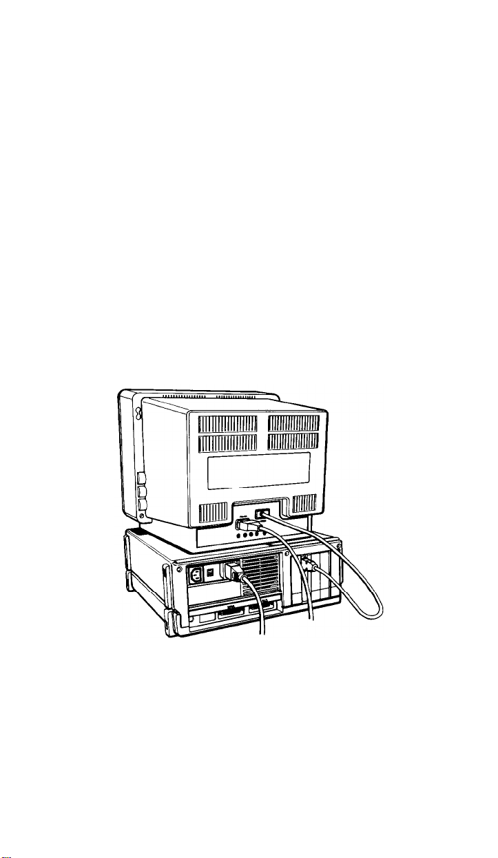
most common setup, shown in Figure 1-1, is to lay the main unit flat and set
the video monitor on top of it with the keyboard directly in front (leaving
enough space to insert diskettes into the disk drives).
First decide how you want to arrange your system components. The
Figure 1-1. System arrangement
Of course, if you have special computer furniture or want to customize
your setup, you can arrange your Equity I+ components to suit your own
particular needs.
1-3

Before you connect the cables, take a look at the rear and front panels of
the main unit.
The
rear panel
Look at the rear panel to identify the Equity I+ input/output ports.
Figure 1-2 shows where you connect the peripheral devices.
WARNING: Do not connect the power cord until you have con-
nected all peripheral devices. Always check to see
that the power switch is off before you connect or
disconnect any peripherals.
AC
outlet
/
--
--
L
Power inlet
\
I//
RS-232C serial port
Here are brief descriptions of each of the ports:
l
AC power outlet. Auxiliary power outlet. Some monitors (and other
types of peripherals) can be plugged into the main unit here, instead of a
wall outlet. The main unit’s power switch controls the monitor or
peripheral connected to this outlet. Power consumption should not
exceed 80 watts.
/
Parallel port
Figure 1-2. Rear panel
OptiXard
access slots
l
AC power inlet. Supplies electrical power to the computer. Always turn
the power switch off before you plug the power cord into an outlet.
1-4

RS-232C serial port. Allows you to connect a peripheral with a serial
interface, such as a modem, another computer or a printer.
Parallel port. Allows you to connect a peripheral with a parallel interface, such as a printer or plotter.
Option card access slots. The Equity I+ has space for five option cards
(which control your peripherals). One of these slots is occupied by either
your monochrome or color/graphics video card. You can use the other
four to add special devices such as a modem or hard disk controller.
The front panel
Now take a look at the front panel. The components on the front panel
are shown in Figure 1-3 with the covers open to show the switches and the
keyboard cable socket. To open each cover, press down gently on the small
handle.
Disk lock/release button
Disk drive
\
LED lamp
Power LED lamp
/
- Power
switch
C?ption?l /
:I% dr’ve
/
RESET/
button
/
Figure
I
DIP switches
CPU speed switch
1-3.
Front
panel
\
\
\
\
Keyboard
cable socket
The front panel components work as follows:
l
Disk lock/release button. Press to lock a diskette in place. Press again to
eject it.
l
Disk drive LED lamps. A light indicates that the drive is being accessed.
1-5

Slot for optional disk drives. You can install a second floppy disk drive or
a hard disk drive in this optional slot. All Equity I+ units come with at
least one floppy disk drive. The main unit above is shown with a second
floppy disk drive.
Power LED lamp. When the light is red the power is on and the system is
running at 4.77MHz. When the light is green the system is on and running at 10MHz.
Power switch. Turns the main unit on and off.
Keyboard cable socket. The keyboard plugs into the main unit here.
RESET
ating system diskette is in the top drive or running on the hard disk, you
can press the RESET button to reboot it.
DIP switches. These give the computer information about its keyboard,
coprocessor status, memory size, monitor type, floppy disk drives, and
interface types. You set them to match your system requirements.
CPU Speed switch. Move this switch left for 4.77MHz or right for
10MHz.
button. Press this button to reset the computer. When an oper-
Connecting the Power Cord
4
back panel, as shown in Figure 1-4. To avoid an electric shock, be sure to plug
this end into the main unit before plugging the other end into the wall
socket. For now, do not plug the power cord into an electrical outlet.
Insert the power cord into the AC power inlet on the left side of the
1-6
Figure 1-4. herring the power cord
Connecting the Video Monitor
5
Equity I+ main unit. It is easiest to connect the monitor cable if the backs of
the monitor and the main unit are facing you.
Note: Your dealer probably installed a video card in your main unit to
Refer to your monitor manual or follow these guidelines:
1.
2.
To connect the video monitor, place it on top of or near the
control your monitor. If not, you need to install it before you can
connect your monitor. See Chapter 3 for installation instructions.
The way you connect your monitor depends on the type you have.
If necessary, connect the video monitor cable to your monitor. Some
cables are permanently attached to the monitor at one end.
Connect the appropriate end of the video monitor cable to your monochrome or color/graphics card connector at the back of the main unit,
as shown in Figure 1-5. If the plug has retaining screws, tighten them
with a screwdriver.
Figure 1-5. Connecting the monitor cable
The monitor type must match the video card in the main unit. If you
have a color card, you can use either a nine-pin female D-connector for
RGB monitors or an RCA connector for composite video monitors.
Consult Table 1-1 to make sure your card and monitor match. Be sure to
set the switches on the video card to match your monitor.
1-7
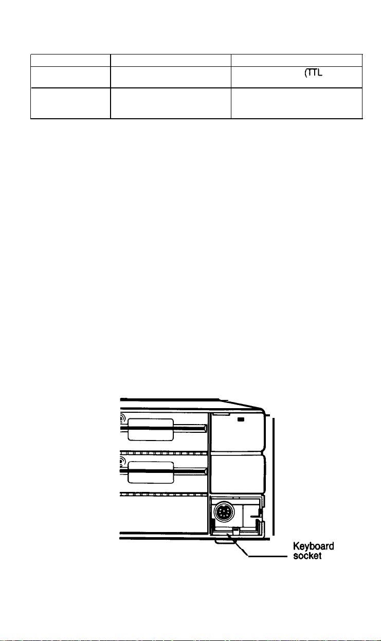
Table 1-1. Monitor/video curd
compatibility
Monitor
Monochrome
Color or
Enhanced color
3.
Plug the monitor’s power cable first into the power inlet on the monitor
and then into an electrical outlet. If a monochrome monitor has the
proper type of plug, you can plug it into the auxiliary outlet next to the
power inlet at the back of the main unit. The monitor’s power consump-
tion must not be more than 80 watts.
4.
When you check the DIP switch settings, as defined later in this chapter,
be sure they are set correctly for the type of monitor you have.
5.
If you have trouble getting a display, check that the brightness and con-
trast controls on the monitor are set correctly. Monitors usually have
their own power switches. Make sure the power switch is on.
Video card
Monochrome or graphics
or enhanced graphics
Graphics or color graphics
or enhanced graphics
output type
One 9-pin output
compatible)
One 9-pin RGB output, or one
RCA-type jack for composite
video
FL
Connecting the Keyboard
6
1.
Follow these steps to connect the keyboard:
Open the cover at the lower right front corner of the main unit, as
shown in Figure 1-6.
1-8
i
Figure 1-6.
Opening
KeyPqard
SocKeI
cover
the keyboard socket cover

2.
Insert the keyboard connector as shown in Figure
1-7.
Do not force the
connector, but make sure you insert it all the way. See that the cable exits
to the right of the main unit.
Figure
1-7. Connecting the cable to the main unit
3.
Gently push the cable into the retaining clip, and close the cover.
You can use the keyboard at different angles such as laying it flat on a
desk or placing it on your lap. You can also tilt the keyboard by adjusting the
legs on the bottom. Adjust the keyboard legs by turning the keyboard over,
reaching under the lip and pulling each of the legs upward until they lock
into place, as shown in Figure 1-8.
1-9

Figure 1-8. Adjusting the keyboard legs
To lower the legs, gently squeeze the sides until they move out of the slot
and push down on the leg until it clicks into place.
To disconnect the keyboard, open the cover on the main unit and press
down on the retaining clip to release the cable. Lift the tab on the connector,
and pull it straight out from the main unit.
Connecting the Printer
7
Your Equity I+ has both serial and parallel built-in interfaces. You
can easily connect a printer or plotter that has either a serial or parallel
interface. Just follow the instructions below.
Parallel interface
The parallel connector on the Equity I+ is a CentronicP-compatible
interface with a DB-25 socket. Most Epson printers have a parallel interface.
1-10

To connect your printer to a parallel interface:
1.
Place the printer in a convenient location next to your system, as shown
in Figure 1-9 for example.
Figure 1-9.
2.
Before connecting any cables, make sure the power switches on both the
main unit and the monitor are switched off, If you are not sure which
cable you need, consult your dealer.
3.
One end of the printer cable has a 25-pin male D-connector. (Refer to
your printer manual to determine which end this is.) Connect this end
to the socket marked
the plug has retaining screws, tighten them with a small screwdriver.
4.
Connect the other end of the cable to the printer. To secure the cable,
tighten the squeeze locks at each side of the printer port and into the
connectors on each side of the cable as shown in Figure 1-10.
PARALLEL
Locating
the printer
on the back panel of the main unit. If
1-11

Squeeze locks
Figure 1-10. Connecting the printer
5.
Plug the printer’s power cable into a separate electrical outlet.
y
Serial interface
If you have a printer (or other peripheral, such as a modem) with a serial
interface, connect it to the port marked SERIAL (RS-232C) at the back of
the main unit. If the cable is a non-standard type, with a male D-connector
at both ends, you need an adapter to connect it to the computer. To connect
your serial device, follow the same steps above for connecting a parallel
device.
The RS-232C serial port needs to be configured properly in order for it
to function correctly. The printer output must also be redirected to the serial
port instead of the parallel port. Use the MS-DOS SETMODE utility (or the
MODE command) to make these changes. See your MS-DOS manual for
instructions.
The Equity I+ character set
The Equity I+ uses a special character set that assigns graphics and inter-
national characters to some of the ASCII codes. In most cases, if you try to
print these characters on a standard printer, you get italic characters instead.
Many Epson printers support the IBM character set (like those used on the
Equity I+) as a standard feature, and other printers can be adapted. In addition, some application programs print the special graphics characters on a
standard printer using a special printer driver program. Ask your dealer for
more information.
1-12

Setting the DIP Switches
8
with information about itself. Each time you turn on your system, it checks
the DIP switch settings to determine the keyboard type, coprocessor status,
memory size, monitor type, number of floppy disk drives, and the typo of
interfaces being used. The DIP switches are located underneath the cover on
the front of your main unit, below the disk drives, as shown in Figure 1-11.
The DIP switches on the Equity I+ are set to provide your system
Figure 1-11. Location of DIP switches
Your Epson dealer should have set these switches for you. However, read
this section to be sure the settings match your system configuration. If you
upgrade your computer later (by adding a hard disk drive for example) you
may need to alter the DIP switch settings.
Note: Set the DIP switches only while your computer is off. Software pro-
grams check the settings each time you turn on the system, so do not
change the settings while a program is running.
The Equity I+ has two sets of DIP switches; set 1 contains eight switches
which control the computer’s internal operations, and set 2 contains four
switches which control the parallel and serial ports. A label inside the DIP
switch cover show; the functions of each DIP switch and the factory settings.
See Figure 1- 12.
1-13

SWITCH I
WBNPE
COPROCESSOR
NO.OFFDMS) 1
I
” I
ENHANCED
NOTINST
MONOCHROME
SINGLE
(DUAL
12345678
OFF
ON
I ON
OFF ON
ON OFF
OFFOFF
ON Oh
OFF Oh
SWlTCHll [
PARALLEL
iPRIMARY
SECONDARY
SABLE
IDISABLE
12 3
OFF ON
_.. _.
OFFOFF
ON ON
41
1
1
I
ONI
Figure 1-12. DIP
switch label
When a switch is up, it is on. When a switch is down, it is off. To change
a setting, use a hard, thin object, such as a small screwdriver.
DIP switch set 1 (internal operations)
The system functions controlled by each switch in set 1 are listed in
Table 1-2 and described below.
Table
1-2. DIP switch set 1
1-14

Switch
1 (keyboard)-tells your computer what kind of keyboard is attached
to your system. The factory setting is off for the standard (enhanced) key
board which comes with your Equity I+.
Switch
2 (coprocessor)-tells your computer whether or not an optional math
coprocessor is installed. The factory setting is on to tell the system that this
option has not been installed.
Switches 3 and 4 (memory size)-indicate how much built-in memory is avail-
able. These switches should never be changed unless you install a memory
card and you want to use part of the optional memory instead of the built-in
main memory.
The system always checks the amount of available memory each time it is
reset. Problems may occur if the switch settings do not agree with the
amount of main memory in use.
Switches
5 and 6
(monitor
type)-define what type of video card and monitor
you are using and help the system address the adapter memory correctly. Set
these switches as follows:
l
If you have a monochrome monitor and video card, set both switches
Off.
l
If you have an enhanced graphics adapter set both switches on, no matter what type of monitor you have.
l
If you have a color graphics adapter and an RGB monitor, set switch 5
on and switch 6 off.
l
If you are using a composite video monitor, and its resolution is poor,
you may want to set switch 5 off and switch 6 on. This selects 40-column
text mode for your screen and improves the resolution.
Switches 7
and
8 (floppy disk drive) -indicate how many floppy disk drives
your system has. These switches are very important and should be set as
follows:
l
If you have a single drive, set both switches on so the operating system
knows that it must provide help when disk B: is required.
l
If you have two floppy disk drives, set switch 7 off and switch 8 on so the
lower drive is not ignored.
l If you add external floppy disk drives, for a system total of four, set
switches 7 and 8 as indicated in Table 1-2.
1-15

DIP switch set 2 (parallel and serial port operations)
The parallel and serial port functions controlled by DIP switch set 2 are
listed in Table 1-3 and described below.
Table 1-3. DIP switch set 2
Switches 1, 2, 3,
and serial ports. You do not need to change the factory settings unless you
install an option card with an additional parallel or serial port. If you do
install such an option card, read the following information carefully.
Switches 2 and 2 (parallel port)-tell the computer how to access the built-in
parallel port.
The built-in parallel port functions as either the primary or secondary
parallel port. However, if you install any option card with its own parallel
port, you must set these two DIP switches so there is no conflict between the
built-in parallel port and the added card. Table 1-3 shows you how to set the
DIP switches.
If you install an option card that has only a parallel port, you must
designate this as the secondary port and leave the built-in port as the primary port.
If you install a video card with a parallel port (such as an IBM monochrome display and printer adapter) you must designate it as the primary
parallel port and the built-in port becomes the secondary parallel port.
If you install two option cards with parallel ports, one is designated as
the primary port and the other as the secondary port. In this case, you need
to set switches 1 and 2 on in order to disable the built-in port.
and 4 tell the computer how to access the built-in parallel
If MS-DOS searches the system for a parallel port and finds only one, it
names it LPT1:. If there are two parallel ports, it names the primary port
LPT1: and the secondary LPT2:.
1-16

Switches 3 and 4 (serial port)-tell the computer how to access the built-in
serial port.
The built-in serial port functions as either the primary or secondary
serial port. However, if you install any option card with its own serial port
you must set these two DIP switches so there is no conflict between the built-
in serial port and the added card. Table 1-3 shows how to set the DIP
switches.
If you install an option card with a serial port preset as primary by the
manufacturer, you must designate it as the primary port and designate the
built-in port as the secondary port.
If you install an option card or peripheral with a serial port not pre-set
you must designate it as the secondary serial port and the built-in port as the
primary serial port.
If you install two option cards with serial ports, one is designated as the
primary port and the other as the secondary port. In this case you need to set
switch 4 on to disable the built-in port.
If MS-DOS searches the system for a serial port and finds only one, it
names it COM1:. If there are two serial ports, it names the primary port
COM1: and the secondary COM2:.
1-17

Turning On the Computer
After you set up your system, you’re ready to turn on the power and
9
start using your Equity I+. But before you do turn it on, read the following
safety rules.
Safety rules
1.
Never turn the computer on or off with a disk drive protector sheet in
the disk drive.
2.
Do not attempt to dismantle any part of the computer. Only remove the
top cover to install and remove option cards. If there is a hardware
problem you cannot solve after reading Chapter 4 on troubleshooting,
or if you want to install an optional 8087 math coprocessor, consult your
Epson dealer.
3.
To install or remove option cards, always turn off the power, disconnect
the main power cord, and wait for a few minutes before removing the
cover from the computer.
Do not unplug cables from the computer while the power switch is on.
4.
5.
Never turn off or reset the computer when one of the drive lamps is on.
This can destroy data stored on a disk or make a whole disk unusable.
6.
Always wait at least five seconds after you switch the power off before
switching it on again. Turning it off and on rapidly can damage the
computer’s circuitry.
Never leave a beverage on top of, or next to, your system or any of its
7.
components. Spilled liquid damages the circuitry of your components.
Now you are ready to turn on your system. It’s a good idea to turn on
the monitor and any peripheral devices before you turn on the main unit.
First, make sure the power cord is plugged into the power inlet on the
back panel of the main unit. Then plug the power cord into a three-prong,
120-volt, grounded electrical outlet. Turn on the monitor so you can see the
messages that appear as your computer starts up. If you have a printer or
other peripheral device, turn it on next.
1-18

You can turn on your computer with or without a system diskette in the
top disk drive. For now, leave the drive empty. When you are ready to turn
on the computer, press the power switch at the upper-right corner once. The
power indicator on the front panel lights up and the cooling fan inside the
main unit starts. After a few seconds, the computer begins to perform an
internal test.
If you cannot see the screen display clearly, use the controls on your
monitor to adjust the brightness and contrast until characters on the screen
are clear and bright. If the display is not stable, check your monitor’s horizontal and vertical hold controls.
Initial setup procedure
If this is the first time your Equity I+ has been used, you need to use the
diagnostics diskette to perform an initial setup. This is a simple procedure
which you must do at least once. You may need to do it again if you change
your system time or date or serial port options. See your Diagnostics manual
for instructions.
Initial screen display
After the computer completes its self test, a message tells you how much
RAM (random access memory) is available, for example:
640KB OK
Then the following message displays:
Non-system disk or disk error
Insert system diskette in drive A:
and strike any key when ready.
This tells you that the computer can now load an operating system from a
diskette in the top drive. The Equity I+ needs a disk operating system (DOS)
to function. It comes with MS-DOS version 3.2. If you want to use another
operating system, consult your Epson dealer.
To load an operating system, insert the system diskette you want to use
(see “Inserting and removing diskettes” in Chapter 2). Refer to your
MS-DOS (or other operating system) manual for details on how to use the
system.
Note:
Use only a backup copy of the system diskette for daily use and keep
the original in a safe place. See your MS-DOS manual to find out
how to make a backup copy.
1-19

If your system has a hard disk, you need to prepare it before you can run
an operating system on it. Refer to “Using a hard disk drive” in Chapter 2
(and to your Diagnostics and MS-DOS manuals) for instructions on how to
prepare a hard disk for use.
If your hard disk has been properly prepared and set up to automatically
boot MS-DOS, the message above does not appear. Instead, the operating
system loads when you turn on the computer. The date and time prompts
display and then the system prompt:
c>
This indicates that the hard disk has been assigned as drive C.
1-20
Chapter 2
Using Your Equity I+
Once you have set up your Equity I+, you’re ready to take advantage of
its versatility. This chapter describes the special keys on the keyboard, how to
change your computer’s operating speed, and how to reset and turn off your
computer. It also explains how to use and care for your disks and disk drives.
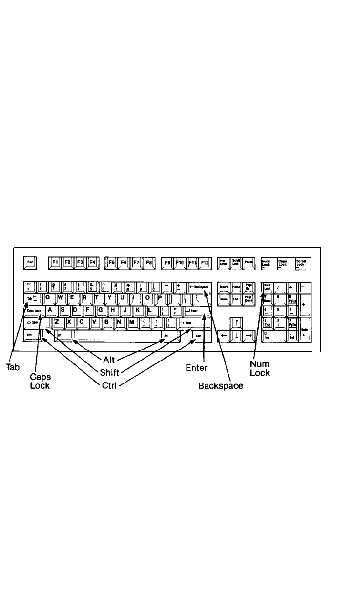
Special Keys
Certain keys serve special functions and are used in various ways by
application programs. Some of the more important keys are shown in Figure
2-1. Table 2-1 describes each of these keys as well as others with special
functions.
Figure 2-1. Equity I+ keyboard
2-1
 Loading...