

Page 1
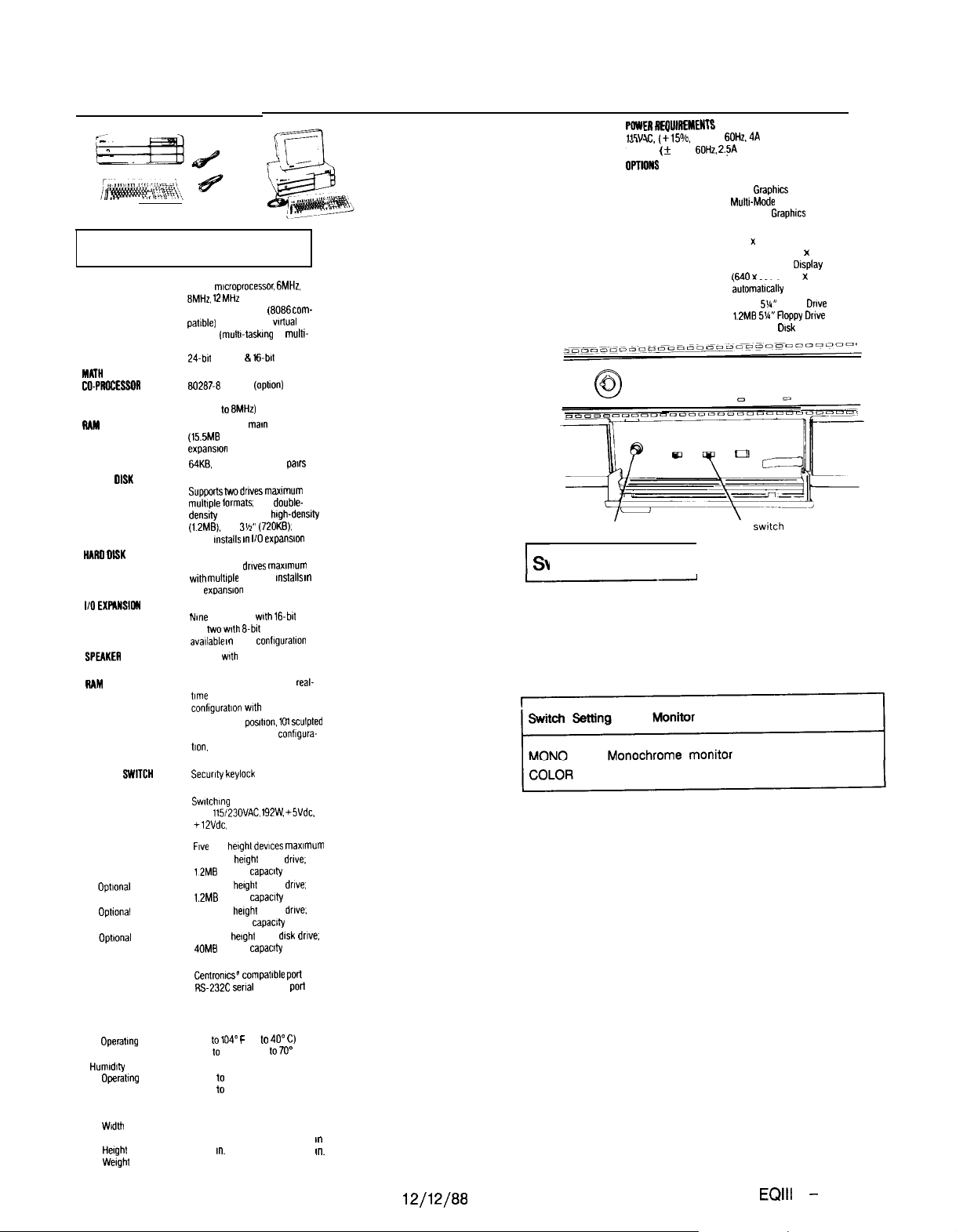
Computer Specifications
80286
CPU
MATH
CO.PfKlcESSOA
RAM
ROM
FLOPPY OISK
CONTROLLER
HARO OlBK
CONTROLLER
l/O EXPANSIOW
SLOTS
SPEllKEn
CLOCK/CALENDAR
RAM
KEYBOARD
KEYLOCK
BWITCH
POWER SUPPLY
MASS STORAGE
Standard
Optional
INTERFACES
Standard
Standard
ENVIRONMENTAL
REQUIREMENTS
Temperature
Operatmg
range
Storage range
Humrdrty
Operatmg
range
Storage range
PHYSICAL CHARACTERISTICS
Width
Depth
Herght
Werght
mlcroprocessor. 6MHz.
8MHr.
12MHz
speeds; real address (8086 com-
paltble) and protected
address (multr-taskmg or mUltl-
user) modes
24.brl
80287-8 support
Co-processor clock speed selectable (up 10 8MHz)
640KB RAM on
(155MB RAM max. with memory
expansron cards)
64KB. Selectable EPROM pairs
Supportstwodrrvesmaxrmom with
multrple lormats;
densdy (360KB). 5%” lugh-density
(l.ZMB). and
troller
Supportstwo
wrth
I/O exoanslon slot
Nme
and two wrth 8-bd bus. seven
avaIlable I”
Internal wrth volume control
64 Bytes of CMOS RAM for real-
lime
conhguratlon with battery backup
tlon. 12 function keys. enhanced
selectable clock
virtual
address 8 16.brt data bus
(option)
mar”
system board
5%”
double-
3h” (7201(8).
mstalls I” l/O expans,on
droves maxrmum
mullrple formats.
total: seven wrth
base
clock, calendar. and system
Detachable, 3
keys, 58 key QWERTY
AT style
Security keylock for cover and
keyboard
Swrtching type, fan cooled, world-
wide
115123OVAC. 192W. +SVdc.
+lEVdc, -5Vdc. -12Vdc
Five
half
height deuces maximum
5 25” half
height
12MB storage capacity
5 25” half
herght
1.2MB
storage capacltV
5.25” hall
herght
360KB storage capacdy
5.25” lull helghl hard
40MB storage capacity
Centron& compabble port
Rs-232C serlal Interface port
41”
to1040 F
19.6
17.4
6.6
m.
I”.
m.
Ibs.
(5” 10 40”
22” 10 158” F (-5”
10% 10 80% non-condensing
10% 10 90% non-condensing
CPU
31.9
mstalls I”
16.bll
conflguratlon
posrtron. 101
COflflgUra-
lloppy
floppy
floppy
drsk drive.
lo70”
con-
scufpled
drove;
drive;
drove.
C)
C)
Keyboard
bus
19.3
7.7
1.8
39
slot
I”.
I”
I”.
Ibs.
EQUITY III + (12 MHz)
E” nry”lnrnrnl”
,I.. xc.
(+15%. -20%); 60Hz,4A
230VAC. ( f 15%).
0PnoNs
Display Adapters
Monitors
Mass Storage
VOLUME control knob
Switch Settings
r
I-
There are no DIP switches on the Equity Ill +. However,
there is a MONITOR SELECT switch, a CPU SPEED switch
and a VOLUME CONTROL on the front of the unit in the
lower left hand corner.
Monitor Select
Color, composite, EGA, and VGA monitors
The CPU SPEED switch selects between 6 MHz, 8 MHz, and
12 MHz. When the computer is running at 6 MHz the power
light is red, at 8 MHz, the light is orange, and at 12 MHz,
the light is green.
60HZ.
Z.>A
Monochrome Display Adapter
Color Graphrcs Adapter
Multi-Mode Graphics Adapter
Enhanced
Monochrome Display
(720 x 350 dots)
Color Display (640 x 200 dots)
Enhanced Color Drsplay
f64l’l x
350 or 640 x 200 dots
&tomatrcally
360KB
5U”
1.2MB 5U”floppy Drove
40MB Hard
CPU SPEED
swrtch
I
Graphrcs
selectable)
Floppy
Orsk
Drive
Adapter
Drove
Equity Series Computers
12/l 2/88
EQlll
+ - 1
Page 2
EQUITY Ill+ (12 MHz)
Connector Pin Assignments
Parallel Port Connector
13
00000000000
25
00000000000
PIN NO.
1
2 DATA0
3 DATA1
4 DATA2
5 DATA3
6
7 DATA5
0
9 DATA7
10
11
12
13
14
15
16
17
16 GND
19
20
21
22
23 GND
24
25
SIGNAL
-
STROBE
DATA4
DATA6
-
ACK
+ BUSY
+PE
+ SLCT
- AIJTOFT
-
ERROR
- INIT
- SLCTIN
GND
GND
GND
GND
GND
GND
NAME
Serial Port Connector
12345
(od)
[o
PIN NO.
9
o o
6 7 8 9
SIGNAL NAME
CRDET
RXDT
TXDT
DTR
SG
DSR
RTS
CTS
RI
oJ
DIRECTION
0
0
0
0
0
0
0
0
0
I
I
I
I
I
I
I
I
DIRECTION
I
DESCRlPTKlN
Printer Data Bit 0
Printer Data Bit 1
Printer Data Bit 2
Printer Data Bit 3
Printer Data Bit 4
Printer Data Bit 5
Printer Data Bit 6
Printer Data Bit 7
Acknowledge
Printer Busy
End of Paper
Printer Select
Auto Feed
Printer Error
Printer
Inltiallze
Prlnter Select
In
Ground
Ground
Ground
Ground
Grwnd
Ground
Ground
Ground
DESCRIPTION
Data Carrier Detect
Receive Data
Transmit Data
Data Terminal Ready
Signal Ground
Data Set Ready
Request to Send
Clear to Send
Ring Indicator
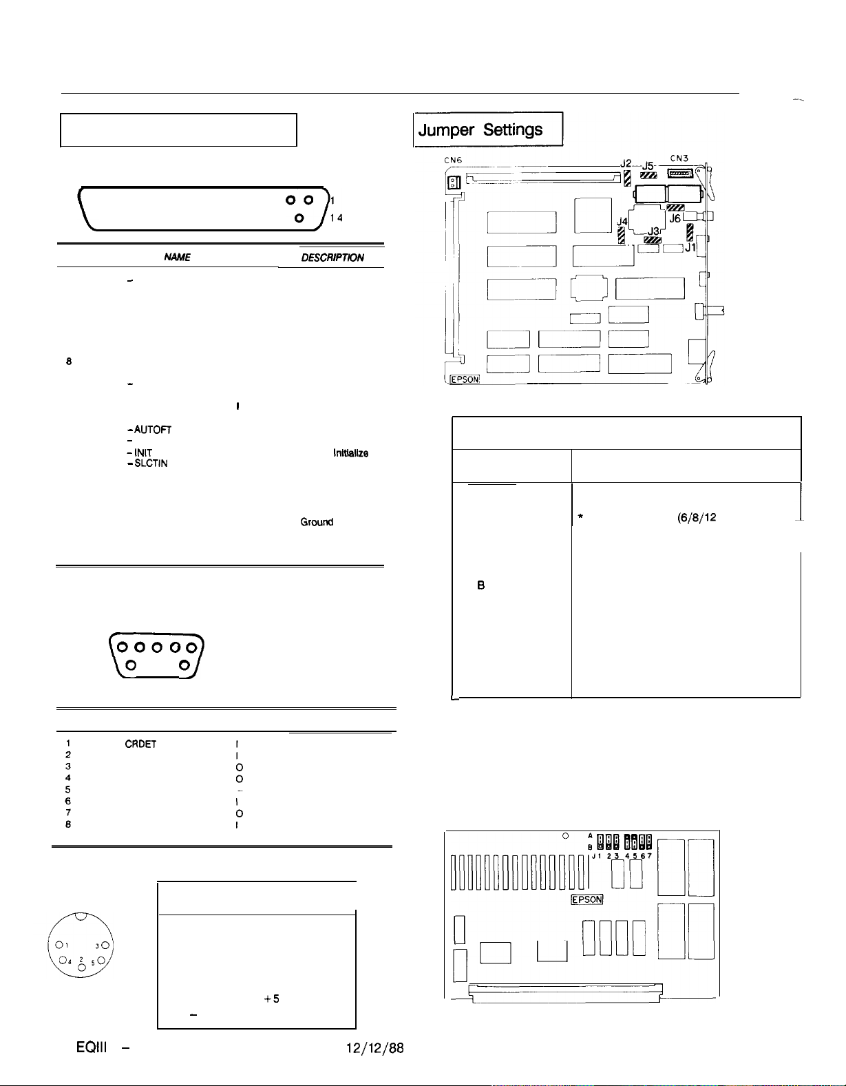
Main Circuit Board
Jumper
123456
A
B
A A
B A
A B
B
B
A
B
A A *
B A
A B
B B
L
* Factory Settings
Notes:
Selectable wait states only available at 12 MHz.
1.
Wait cycles for external 16-bit devices. These
2.
selectable wait cycles are available at 12 MHz only.
Prohibited
*
Set CPU clock
(6/8/12
Prohibited
Use CPU clock for NPX clock
* Use 8 MHz clock for NPX clock
Prohibited
* 2 wait cycles for EPROM (note 1)
1 wait cycle for EPROM (note 1)
4 wait cycles (note 2)
3 wait cycles (note 2)
2 wait cycles (note 2)
1 wait cycle (note 2)
Function
MHz)
Keyboard Connector
I
Pin Number
EQlll
+ - 2
Signal Name
1
Clock
2 Data
3
4
5
-
Not Connected
Ground
+5
Ground
VDC
I
I
12/l 2188
Equity Series Computers
Page 3
EQUITY Ill + (12 MHz)
Memory Board
Jumper
1234567
A A A
B A A
B B A
B B B
A A
B B
A A
B B
* Factory Settings
Function
* RAM 640KB
RAM 512KB
RAM 256KB
RAM OKB
EPROM 21728 type
* EPROM 27256 type
* Select ROM sockets
24A and 248
Select ROM sockets
23A and 236
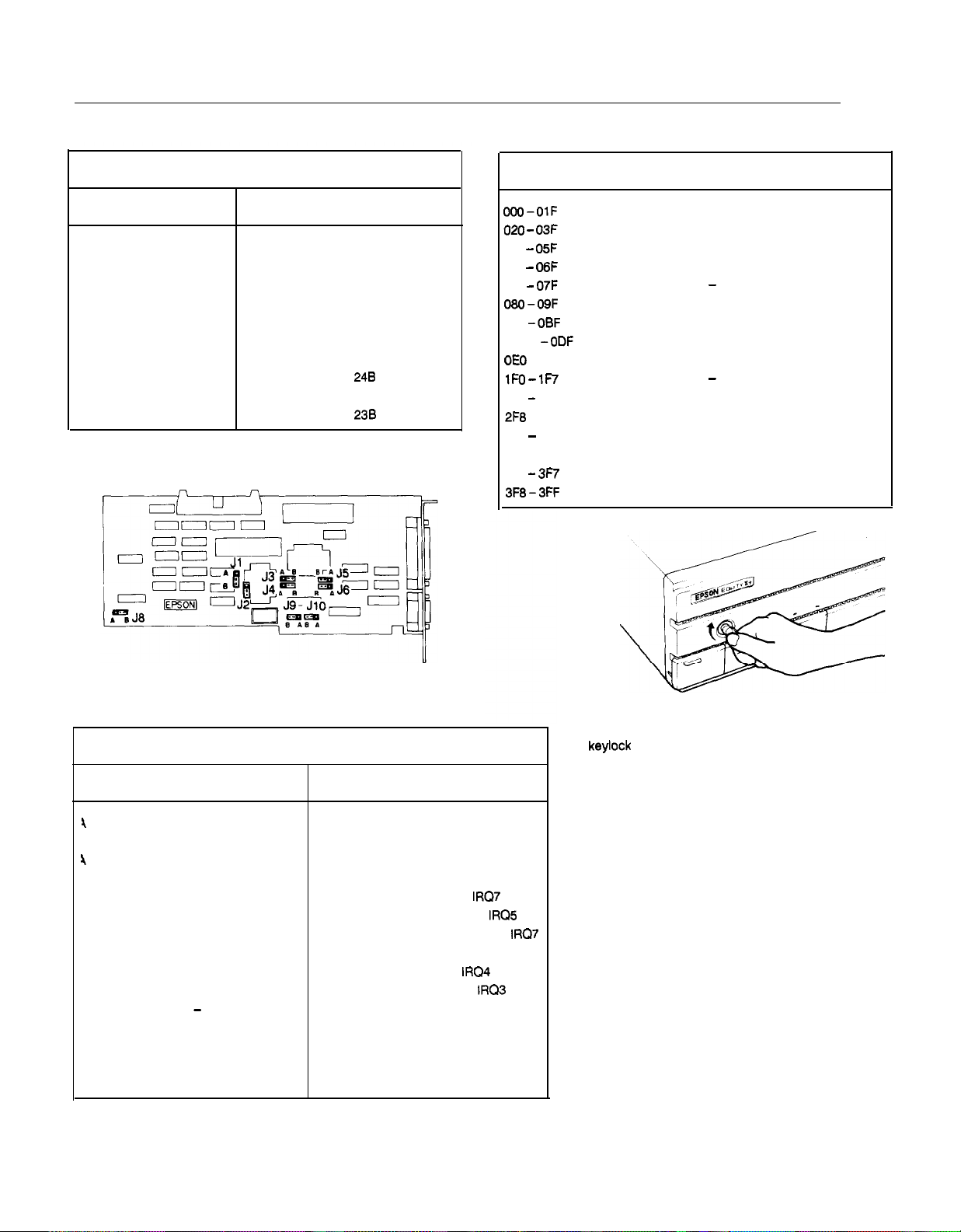
I/O Port Addresses
Address
OOO-OlF
020 -
040 - 05F
060 - 06F
070 - 07F
080-09F
OAO
-0BF
OCO
OE0
-OFF Numeric Coprocessor
1FO -
278 - 27F
2F8
-2FF Serial Port 1
378 - 37F
3BC -3BF Parallel Port 2 (on some video boards)
3Fo - 3F7
3F8-3FF
DMA Controller 1
Interrupt Controller 1
03F
Timer/Counter
Keyboard controller and Port B
CMOS RAM and Non - Maskable Interrupt Mask
DMA Page Register
Interrupt Controller 2
-0DF
DMA Controller 2
IF7 Hard Disk Controller - Primary
Parallel Port 1
Parallel Port 0
Floppy Disk Controller
Serial Port 0
Function
Multifunction Board
lumper Function
I 2 3 4 5 6 7 8 9 10
4
A
3 A
4
B
3 B
A A
A B
B A
B B
A A
A B
B
l Factory Settings
A
B
-
A
B
A
B
* Primary register set (AT FDC)
Secondary register set (AT FDC)
PC register set (FDC)
Disable FDC register set
* Primary parallel I/F,
A
B
A
Secondary parallel I/F,
Video adapter parallel I/F,
Disable parallel I/F
* Primary serial I/F,
Secondary serial I/F,
Disable serial I/F
* AT compatible FDD I/F
Equity III FDD I/F
* Standard setting
Test mode of VCO
IRQ7
IRQ4
IRQ5
IRQ3
IRQ7
Keylock
The keylock on the front panel allows you to disable the
keyboard and RESET button and lock the top cover of the
main unit for security. The keyboard may be locked while
the system is in operation. This disables the keyboard SO no
one can interfere with the current operation.
To lock the system, insert the key with the notch pointing
left and turn it clockwise. You must press it in slightly when
you turn the key. To unlock it, insert the key with the notch
pointing up and turn the key counterclockwise. You can
remove the key in either position.
Equity Series Computers
12/12/88
EQIII + - 3
Page 4
EQUITY III + (12 MHz)
DMA Channels
--
Channel
I
0 Spare
1
2
3
4
Spare
floppy disk transfers
Spare (Hard disk drive)
Cascade
5 Spare
6
7 Spare
Spare
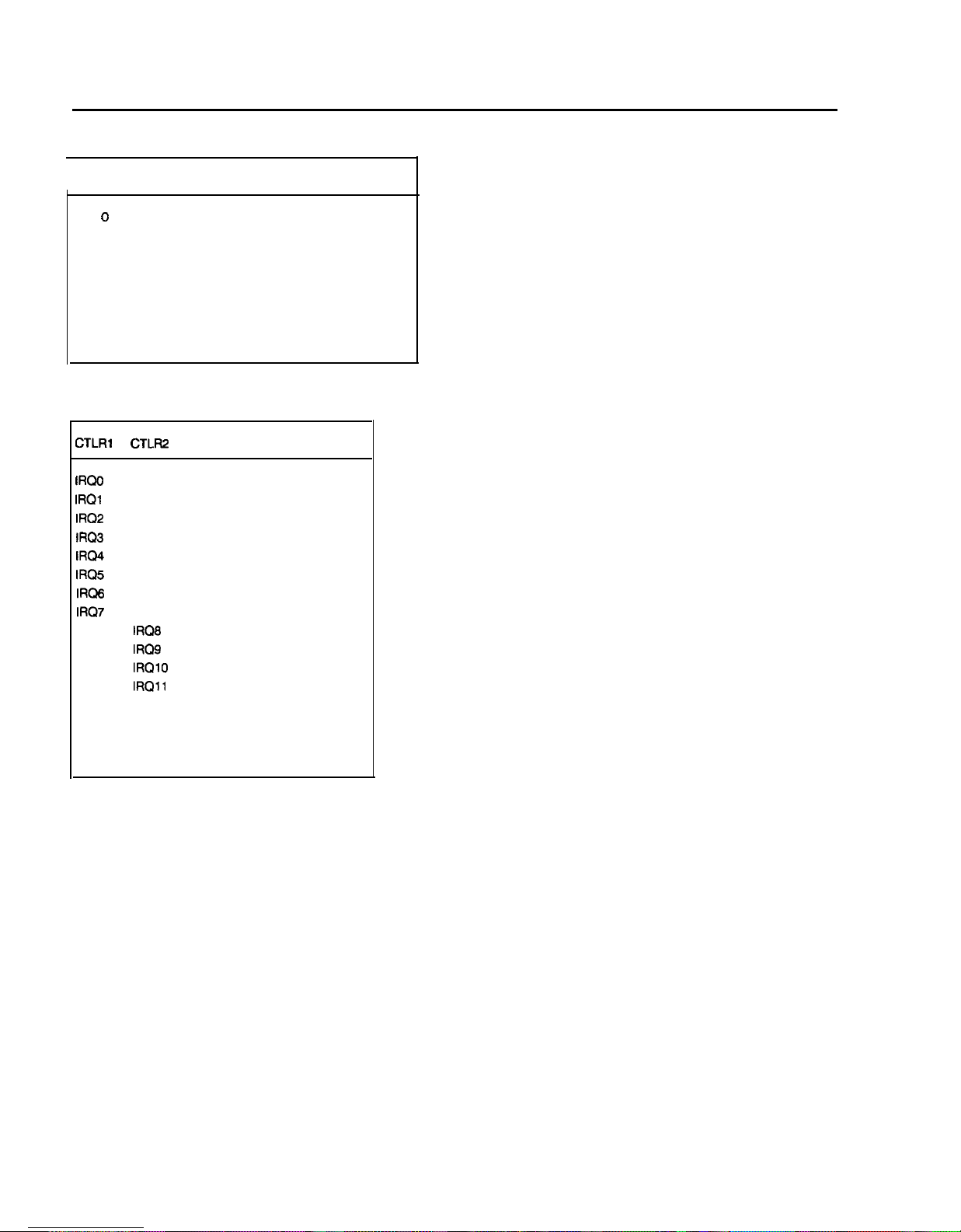
Hardware Interrupts
CTLRl CTLFI2
IRQO
IRQl
IRQ2
IRQ3
IRQ4
IRQ5
IRQ6
IRQi’
IRQ8
IRQ9
IRQlO
IRQll
IRQ12
IRQ13
IRQ14
IRQ15
Timer Output 0
Keyboard
Reserved
Serial port 2
Serial port 1
Parallel port 2
Floppy disk interrupt
Parallel port 1
RTC interrupt
Reserved
Reserved
Reserved
Coprocessor
of data from channel
FUNCTION
Reserved
Hard disk controller
Reserved
Function
0
-3
EQlll+ -4 12/12/88
Equity Series Computers
Page 5

EQUITY Ill+ (10 MHz)
Computer Specifications
CPU
MATH
CO-PROCESSOR
RAM
ftOM
FLOPPY OISK
CONTROLLER
HARD DISK
CONTROLLER
l/O EXPANSION
SLOTS
SPEAKER
CLOCWCALENOAA
RAM
KEYBOARD
KEYLOCK
SWITCH
POWEA
SUPPLY
MASS STORAGE
Standard
Optlonal
Optlonal
Opttonal
INTERFACES
Standard
Standard
ENVIRONMENTAL
REQUIREMENTS
Temperature
Dperatmg range
Storage range
HomIddy
Operating range
Storage range
80286
microprocessor, 6MHz.
8MHz. 1OMHz
speeds, real address (8086 com-
patlble) and protected
address (multi-tasking or mulb-
user1
24.bit
80287-E support (optlon)
Co-processor clock speed selectable (up to 8MHz)
640KB RAM on maln system board
I15 5MB
expansion cards)
64KB. Selectable EPROM pairs
Supports two drives
multlple
densQ1360KE),SC”h~gh-dens@
I1 2MB).
troller
Supports two
with multtple tormats, installs
I10 exoanslon
Ntne
and two with E-bit bus. seven
avaIlable in
Internal wdh volume control
64 Byles of CMOS RAM tor real-
bme clock. calendar, and system
conflguratlon with battery backup
Detachable, 3
keys, 58 key
tlon. 12 funcbon keys, enhanced
AT style
Security keylock for cover and
keyboard
Swltchlng type, fan cooled, worldwide 115/23OVAC. 192W. +5Vdc,
+lZVdc. -5Vdc. -12Vdc
Fwe
5 25” half
12MB storage capacity
5.25” halt
1.2ME
5.25” half
360KB storage capacdy
5 25” full
40MB storage capacity
Centronlcs’ compabble port
RS-232C serlal Interface port
41” to 104” F (5” to 40”
22” to 158” F
10% to 80% non-condensing
10% to 90% non-condensing
selectable clock
virtual
modes
address 8
l&bit
data bus
RAM max
wdh
memory
manmum wtth
formats,
5X”double-
and
3%” (720KB).
mstalls in I/O expansion
slot
total, seven with 16.bit bus
base
OWERTY
half
height
height
height
storage capacity
height
hetght
droves
maxImum
conflgurabon
pos~bon. 101
conflgura-
devices
floppy
floppy
floppy
hard
disk drive;
(~5”
to 70”
con-
sculpted
maxImum
drive.
drive;
drive;
C)
C)
slot
III
PHYSICAL CHARACTERISTICS
Width
Depth
Height
Weight
POWER REQUIREMENTS
115VAC, (+
15%. -20%);
23OVAC. (?
15%).
OPTIONS
Display Adapters
Monttors
Mass Storage
VOLUME control knob
1
Switch Settings
1
There are no DIP switches on the Equity
CPU
19.6
I”.
17.4 I”.
6.6 I”.
31 9 Ibs
60Hz.
6OHz. 2.:A
4A
Monochrome Display Adapter
Color Graphics Adapter
-Multi-Mode
Enhanced Graphics Adapter
Monochrome Display
(720 x 350 dots)
Color Display (640 x 200 dots)
Enhanced Color Display
(640 x 350 or 640 x 200 dots
automabcally selectable)
360KB 5%” Floppy Dove
1.2MB
5%” Floppy Drive
40MB Hard Disk Drive
CPU SPEED
switch
Keyboard
19.3
Graphzs Adapter
Ill+.
However,
7.7
1.8
3.9
I”.
I”.
I”.
Ibs.
there is a MONITOR SELECT switch, a CPU SPEED switch
and a VOLUME CONTROL on the front of the unit in the
lower left hand corner.
Monitor Select
Color, composite, EGA, and VGA monitors
The CPU SPEED switch selects between 6 MHz, 8 MHz, and
10 MHz. When the computer is running at 6 MHz the power
light is red, at 8 MHz, the light is orange, and at 10 MHz,
the light is green.
Equity Series Computers
12/12/88
EQlll + - 5
Page 6

EQUITY Ill+ (10 MHz)
Connector Pin Assignments
Parallel Port Connector
13
25
PIN NO.
1
2
3 DATA1
4
5 DATA3
6
7
6
9
10
11
12
13
14
15
16
17
16
19
20
21
22
23
24
25
SIGNAL NAME
-
STROBE
DATA6
DATA2
DATA4
DATA5
DATA6
DATA7
-
ACK
+ BUSY
+PE
+ SLCT
-
AUTOFf
-ERROR
- INIT
- SLCTIN
GND
GND
GND
GND
GND
GND
GND
GND
DIRECTION DESCRIPTWN
0
0
0
0
0
0
0
0
0
I
I
I
I
I
I
I
I
Serial Port Connector
12345
1%)
6 7 8 9
PIN NO.
1
2
3
4 DTR
5
6
7
a
9
SIGNAL NAME
CRDET
RXDT
TXDT
SG
DSR
RTS
CTS
RI
DlRECTloN
I
I
0
0
‘0
I
I
Printer Data Bit 0
Printer Data Bii 1
Printer Data Bit 2
Printer Data Bii 3
Printer Data Btt 4
Printer Data
Printer
Printer
Acknowledge
Printer Busy
End of Paper
Printer Select
Auto Feed
Printer Error
Printer
Printer Select
Ground
Ground
Ground
Ground
Btt
Data Bk 6
Data
Bit
lnltiallze
In
5
7
Ground
Ground
Ground
Ground
DESCRlPTKlN
Data Carrier Detect
Receive Data
Transmit Data
Data Terminal Ready
Signal Ground
Data Set
Request to Send
Clear to Send
Ring Indicator
Ready
1
Jumper Settings
1
CN6
Main Circuit Board
I
Jumper
I
123456
I
* Set CPU clock
Prohibited
Prohibited
Use CPU clock for NPX clock
l Use 8 MHz clock for NPX clock
Prohibited
A
B
* 2 wait cycles for EPROM (note 1)
1 wait cycle for EPROM (note 1)
* 4 wait cycles (note 2)
A A
B A
A B
B B
3 wait cycles (note 2)
2 wait cycles (note 2)
1 wait cycle (note 2)
* Factory Settings
Notes:
1.
Selectable wait states only available at 10 MHz.
2.
Wait cycles for external 16-bit devices. These
selectable wait cycles are available at 10 MHz only.
(6/8/10
1
MHz)
Keyboard Connector
EQIII + - 6
Pin Number
1
2
3
4
5
Signal Name
Clock
Data
Not Connected
Ground
+5
VDC
Ground
12/12/88
Equity Series Computers
Page 7

EQUITY III + (10 MHz)
Memory Board
Jumper
1234567
A A A
B A A
B B A
B B B
A A
B B
A A
B B
* Factory Settings
Function
* RAM 640KB
RAM 512KB
RAM 256KB
FIAM
OKB
EPROM 21728 type
* EPROM 27256 type
* Select ROM sockets
24A and 248
Select ROM sockets
23A and 23B
I/O Port Addresses
Address
300-OlF
D20 -
040 D6O-06F
Di’O-07F CMOS RAM and Non - Maskable Interrupt Mask
WO-09F
OAO-OBF Interrupt Controller 2
DC0 -0DF
OE0
lFO-lF7
278 - 27F
2F8 - 2FF
378 - 37F
3BC-3BF
3F0 -3F7
3F8-3FF
DMA Controller 1
Interrupt Controller 1
03F
Timer/Counter
05F
Keyboard controller and Port B
DMA Page Register
DMA Controller 2
-OFF Numeric Coprocessor
Hard Disk Controller - Primary
Parallel Port 1
Serial Port 1
Parallel Port 0
Parallel Port 2 (on some video boards)
Floppy Disk Controller
Serial Port 0
Function
Multifunction Board
lumper
2 3 4 5 6 7 8 9 10
\ A * Primary register set (AT FDC)
3 A
\
B
3 B
A A
A B
B A
B B
A A
A B
B
* Factory Settings
-
A
B
A
B
A
-
A
B
-
A
B
Function
Secondary register set (AT FDC)
PC register set (FDC)
Disable FDC register set
* Primary parallel I/F,
Secondary parallel I/F,
Video adapter parallel I/F,
Disable parallel I/F
* Primary serial I/F,
Secondary serial I/F,
Disable serial I/F
* AT compatible FDD I/F
Equity Ill FDD I/F
* Standard setting
Test mode of VCO
IRQ7
IRQ4
IRQ3
IRQ5
IRQ7
Keylock
The keylock on the front panel allows you to disable the
!
-I
keyboard and RESET button and lock the top cover of the
main unit for security. The keyboard may be locked while
the system is in operation.
one can interfere with the current operation.
To lock the system, insert the key with the notch pointing
left and turn it clockwise. You must press it in slightly when
you turn the key. To unlock it, insert the key with the notch
pointing up and turn the key counterclockwise. You can
remove the key in either position.
This disables the keyboard so no
Equity Series Computers
12/12/88
EQIII + - 7
Page 8

EQUITY III + (10 MHz)
DMA Channels
Channel
0
1
2
3
4
5
6
7
Spare
Spare
Floppy disk transfers
Spare (Hard disk drive)
Cascade of data from channel O-3
Spare
Spare
Spare
Hardware Interrupts
CTLRl CTLR2
IRQO
IRQl
IRQ2
IRQ3
IRQ4
IRQ5
IRQ6
IRQ7
IRQ8
IRQ9
IRQlO
IRQll
IRQ12
IRQ13
IRQ14
IRQ15
Timer Output 0
Keyboard
Reserved
Serial port 2
Serial port 1
Parallel port 2
Floppy disk interrupt
Parallel port 1
RTC interrupt
Reserved
Reserved
Reserved
Resewed
Coprocessor
Hard disk controller
Reserved
Function
FUNCTION
EQIII + - 8
12/12/88
Equity Series Computers
Page 9

EQUITY Ill+ (12/10 MHz)
lnstallation/Support Tips
I
Power
The Equity Ill+ has a power supply that is switchable
between 115 V, for USA and Canadian use, and 230 V, for
use in other countries. The voltage switch is located at the
rear of the CPU between the AC inlet and the AC outlet (see
figure below).
Option
Voltage
swtch
AC power
Inlet
AC power
outlet
WARNING! The voltage is not changed between the AC
inlet and the AC outlet.
order to function in Europe, only peripherals certified for use
at 230 V should be plugged into the outlet.
If the CPU is switched for 230 V in
access
RS232C
serial
port
card
slots
Setup
--_
---
When installing an optional expanded memory
board, do not list the memory under the memory
expansion option in SETUP. That option is for
EXTENDED memory ONLY.
If you are installing an EGA or VGA card, select
SPECIAL OPTIONS as display type in SETUP. This
holds true even when you are using a color or
monochrome monitor with these cards.
-
When installing a hard disk drive, be sure to consult
the drive type table (on page EQIII + -7) for the
drive type which fits the drive you are installing.
Third Party Option Boards
---
---
If you find that some third party option boards do
not function properly in the Equity Ill+ at the
higher speed, try setting the CPU speed back to 6
MHz or 8 MHz.
When installing a memory expansion option board,
make sure that it is a board capable of supporting
the higher bus speed (10 MHz or 12 MHz) of the
Equity Ill+. Some boards are rated for no higher
than 8 MHz.
Installing Floppy Disk Drives
---
---
When installing a floppy disk drive as drive 6,
remember to set the drive select jumper to the
second position and attach the pass -through
connector on the floppy drive controller cable to the
drive, not the end connector.
If the drive does not function normally, make sure
that the drive type has been correctly selected in
SETUP. Also check that any special drivers that
may be necessary have been installed correctly.
Installing Hard Disk Drives
---
---
It is recommended that a 16-bit AT -type hard
disk controller be used in the Equity Ill + . If you
must for some reason use an 8-bit XT-type
controller, select drive type NONE in SETUP.
If you are having difficulty in formatting the hard
disk drive, try starting over with the Unconditional
Format option in diagnostics.
Software Problems
--_
---
When installing a copy- protected software package
on the Equity Ill+, set the the CPU speed to 8
MHz. This has been found to have fewer conflicts
with copy-protection. After the installation, the
CPU can be switched back to the higher speed.
If a software package does not appear to be
compatible with the Equity Ill+, try switching the
CPU speed to 6 MHz and/or 8 MHz before giving
up. Some software packages (e.g., Microsoft Chart
1.01 and Think Tank 1.001) have been found to
function only at 6 MHz and 8 MHz.
Equity Series Computers
12/12/88
EQlll+ - 9
Page 10

EQUITY Ill+ (12/10 MHz)
-
Hard Disk Drive Types
ROM BIOS Version 1.02
-
Drive
type
:
3
4
z
i
9
10
11
12
13
14
15
16
17
18
19
20
;:
23
24-47
306
615
615
940
940
615
462
733
900
820
855
855
306
733
6%
977
977
1024
733
733
733
306
-
Heads
4
i
8
6
:
5
15
;
iii
7
-
4
5
7
5
5
4
Write
precom-
pensation
128
300
300
512
512
256
-
-
-
-
-
128
-
-
300
5%
300
300
300
-
-
-
Landing
zone
(cylinder)
305
615
615
940
940
615
511
733
901
820
855
855
319
733
6&
977
977
1023
732
732
733
336
-
10
20
;;
46
20
z:
112
z:
49
20
42
20
40
56
60
30
42
30
10
-
ROM BIOS Version 1.50
and Higher
Drive
type
:
3
9
!
6
i
9
10
11
12
13
14
15
16
17
18
19
20
;:
23
24
25
z
28
29
30
2
33-42
43
44
45
46
47
cdb'x
306
:;:
940
940
615
462
733
900
820
855
~~
733
61:
977
977
1024
733
733
733
306
612
306
612
698
976
306
611
732
1023
0
1024
830
1024
615
0
I
T-
Heads
15
10
I
4
:
:
ii
5
3
5
;
A
4
5
7
5
:
4
4
4
4
5
4
4
5
0
8
5
F!
rK%%
Write
128
E
512
512
21:
-1
-1
-1
-1
12;
-1
300
4:
300
300
300
30:
-1
30;
488
306
300
-1
51;
512
512
128
Landing
zone
(cylinder)
305
615
615
940
940
615
511
733
901
820
855
855
319
733
:
0
0
66:
9-77
977
1023
732
732
733
336
663
340
670
732
977
340
663
732
1023
0
1023
a29
1023
618
0
::
30
62
46
z:
30
112
20
2:
20
42
2:
40
E
30
42
30
::
::
40
41
::
43
43
6:
141
43
40
0
EQlll+ - 10
12/12/88
Equity Series Computers
Page 11

EQUITY III + (12/10 MHz)
Product Support Bulletins
S-O@MA
S-0010
S-0011
SoolM
S-0016
S-0018
S-OOlQB
S-0021
!xo26
215187
3113187
413187
wm
WI87
Ws7
7/29/87
WW7
9/l S/87
12/2/87
1 O/22/87
llflQf87
1
l/19/87
Ml%-MO Board Update for
Equity Ill+ HDD Initialization Procedure
Equity Ill+
Equity Ill+
Equity l+/lll+
MSDCS
Equfty
ARNET -
SC0
Equity/Apex Coprocessor Selection Guide
Equity
Equity
Equity + Series Compatibility Certification
Enhanced CPU Speed
Configuration with 3rd Party
Worldwide Power Selection
3.2 Select Command Manual Error
Ill+
ROM
BIOS Upgrade for Novell
IDEA - 3COM -
- Fox Research - Manzana Certifications
Ill+
(12 MHz)
Ill+
(12 MHz) Archive
the Equity Ill+
SFICNET
introduction
Certification
Utilify
Seleotfon
Options
S-0031
s-0042
SOO47A
S4084B
%I081
12/10/87
12/14/87
lfl2f88
6/12/89
5j16j88
5/4/@
10/12/88
s/9/89
Equity Ill+
Equity Series with Word and Serial Printers
Equity II t
Bquify
Equity Ill t Common Questions and Answers
Using Expanded Memory with Equity and Apex
Equity series wilh
Using Math Coprowssors with Equity and Apex
Equily
Equity Series Computers - ROM History
10
MHz/12 MHz
/Ill
t 40MB CDC HDD Information
Series Power Available and Consumption
t Series Novell
Differences
PLUS
H#xxARD 20
Netware Certificatfons
EQlll+-12
Equity Series Computers
Page 12

EQUITY Ill+ (12/10 MHz)
S-0072
3/16/89
311718.9
4119189
7/12/89
8/l l/89
Using ST251 and ST4095
Micron Technology Expanded/Extended
Apex/Apex Plus/Equity Series Keyboards.
Equity/Apex with the
Using High Capacity ESDI and SCSI
Related Documentation
029okAA
A805011
MTMEQlll +
MPMEQIII +
M-PL-EQ3t lo/12
Y12599112300
5/24/88
HDDs
in the Equity II
RAM
Boards
Sysgen CmniSridge &rrd
HDDs
with the Equity Series
Equity Ill t Software Package.
Equity Ill+ Software Package
MS-DOS 3.3 Upgrade
Equity Ill t Technical Manual
Equity Ill t Programmer’s
Equity Ill t 10 and 12 MHz Parts List
Equity
Ill t (12 MHz) User’s Guide
MSDCS
Referenoe
t/Ill
t
Bridge
3.2 and
Manual
Feiler
Drives
GW-Basic
Y12699100100
Y12599100200
Equity Ill t (10 MHz) User’s Guide
Equity Ill t Diagnostics Manual
Equity Series Computers
9/22/89
EQlll+-13
 Loading...