

Epson Equity III Product Support Bulletin

Product Support Bulletin
Subject: Proper Method for Running Benchmark and Diagnostics Programs
EPSON
Date: 06/04/93
Page(s): 1 of 1
This bulletin describes the proper method for running any benchmark or diagnostics
programs. This applies to any computer system.
In most cases, the computer should be started using an MS-DOS boot diskette
that’s ‘clean’ The appropriate executable can then be run, either from diskette or hard drive.
There will be some exceptions to the above rule. In attempting to benchmark or
troubleshoot any add-on that requires a device driver (CD-ROM, local area network,
etc.), obviously the necessary device driver(s) must be loaded. Also, some
programs will require a minimum number of FILES or BUFFERS to be defined in
the CONFIG.SYS file. Such programs will usually display this requirement if they
are run without the necessary CONFIG.SYS file.
For the most consistent results, use the absolute minimal boot configuration that’s
allowed by the hardware being tested.
in other words, one with no CONFIG.SYS or AUTOEXEC.BAT files.
PSB No: S-0158
Originator: MWT

Product Support Bulletin
Subject:
Date:
Page:
The purpose of this bulletin is to provide the results of compatibility testing
conducted by the Computer Product Support Center with the Sysgen
OmniBridge controller and Bridge - Filer external floppy disk drives.
Equity I
Equity II
Equity and Apex Series Compatibility with the Sysgen OmniBridge
Controller and BridgeFiler External Floppy Drives
04/11/90
1 of 3
PSB No:
Originator:
Comments
The Equity I was found compatible with the OmniBridge
controller. It was able to support one or two external
disk drives (daisychained) together. The external drives
could be used as high density (1.2M and 1.44M) or
normal (360K and 720K) disk drives.
The Equity II was found to be totally incompatible with
the OmniBridge controller.
S-0088B
KAS
60
Equity III
Equity I +
Equity le
The Equity III was found compatible with the OmniBridge
controller. It was able to support one or two external
disk drives (daisychained) together. The external drives
could be used as high density (1.2M and 1.44M) or
normal (360K and 720K) disk drives.
The Equity I + was found compatible with the
OmniBridge controller.
two external disk drives (daisychained) together. The
external drives could be used as high density (1.2M and
1.44M) or normal (360K and 720K) disk drives.
The Equity le was found compatible with the OmniBridge
controller. It was able to support only one external
floppy drive, unlike the other models tested. The drive
could be used as a high density (1.2Mb and 1.44Mb) or
normal (360K and 720K) disk drive.
It was able to support one or

PSB No: S-0088B
Page: 2 of 3
Equity II +
Equity lIe
Equity Ill +
Equity 386SX
The Equity II + was found compatible with the
OmniBridge controller.
two external disk drives (daisychained) together. The
external drives could be used as high density (1.2M and
1.44M) or normal (360K and 720K) disk drives.
The Equity Ile was found compatible with the
OmniBridge controller.
two external disk drives (daisychained) together. The
external drives could be used as high density (1.2M and
1.44M) or normal (360K and 720K) disk drives.
The Equity III + was found compatible with the
OmniBridge controller.
two external disk drives (daisychained) together. The
external drives could be used as high density (1.2M and
144M) or normal (360K and 720K) disk drives.
The Equity 386SX was found compatible with the
OmniBridge controller.
two external disk drives (daisychained) together. The
external drives could be used as high density (1.2M and
144M) or normal (360K and 720K) disk drives.
It was able to support one or
It was able to support one or
It was able to support one or
It was able to support one or
Equity 386/20
APEX
APEX +
The Equity 386/20 was found compatible with the
OmniBridge controller.
two external disk drives (daisychained) together. The
external drives could be used as high density (1.2M and
1.44M) or normal (360K and 720K) disk drives.
The Epson APEX was found compatible with the
OmniBridge controller.
two external disk drives (daisychained) together. The
external drives could be used as high density (1.2M and
1.44M) or normal (360K and 720K) disk drives.
The Epson APEX was found compatible with the
OmniBridge controller.
two external disk drives (daisychained) together. The
external drives could be used as high density (1.2M and
1.44M) or normal (360K and 720K) disk drives.
It was able to support one or
It was able to support one or
It was able to support one or

PSB No: S-008B
Page: 3 of 3
APEX 100
APEX 200
NOTE:
The Epson APEX 100 was found compatible with the
OmniBridge controller.
two external disk drives (daisychained) together. The
external drives could be used as high density (1.2M and
1.44M) or normal (360K and 720K) disk drives.
The Epson APEX 200 was found compatible with the
OmniBridge controller.
two external disk drives (daisychained) together. The
external drives could be used as high density (1.2M and
1.44M) or normal (360K and 720K) disk drives.
The recommended switch settings for the OmniBridge controller are
as follows:
1-1 DOWN 2-1 DOWN
1-2 DOWN 2-2 DOWN
1-3 DOWN
1-4 DOWN
2-3 UP
2-4 UP
It was able to support one or
It was able to support one or
These settings select NO ADDRESS for the OmniBridge BIOS and
allow it to coexist with the internal FDC of the computer in which it
is being installed.
FDC or connect any cables from the OmniBridge to internal floppy
drives. This was found to be a universal setting for all of the
computers listed above as compatible with the OmniBridge controller.
This way you do not need to disable the internal
Product Support Bulletin
Subject:
Date: 4/19/89
Page: 1 of 1
Apex / Apex Plus / Equity Series Keyboards
PSB No: S-0080
Originator: REM
AL
The purpose of this bulletin is to provide information on the various keyboards
used with the Apex, Apex Plus and Equity series computers and the part
numbers of the keyboard subassemblies used with these keyboards.
The Apex and Apex Plus computer keyboards are to be replaced as whole
units.
The Equity series keyboards are repaired to the subassembly level.
The
Equity III keyboard PCB assembly is the only one that comes with the key top
set attached.
Since some of the keyboards have the same model numbers, the difference
can be determined by the FCC ID number in those cases.
The chart below provides a quick reference to determine the part number of
the main keyboard PCB assembly, key top set, control logic subassembly, and
keyboard cable.
Apex / Apex Plus
Model
Apex
Apex Plus
Model
Model
E1160A -
Keyboard
Unit
A265091A
93553905410 Equity Ill
Code
Code
Equity I +, II +, Ill+, 386/20
FCC ID
FCC ID
C9S4D84701-201
Equity I, II, Ill
Model
Equity I/II
Keyboard Control
PCB Assy
Keyboard
PCB Assy
Y145501001 Y145501021
KAFLZ3AEPS1
Board
attached
attached Y127501022
none
Y171501017
Equity le
Keyboard Control
PCB Assy
Y163504007 Y171501017
Board
Key Top
set
attached KACCL060UCA
Key Top
set
Y127501022
Y127501022
Y127501022 Y163504006
Key Top
set
Y171501007
Keyboard
Cable
Y144305000
Keyboard
Cable
Y127501031
Y127501031
Y163502020
Keyboard
Cable
Y171501006

Product Support Bulletin
Subject:
Date:
Page:
Equity Series HDD Controllers Jumper Settings
6/12/89
1 of 8
This bulletin provides information on the jumper settings for the hard
disk controllers used in Epson Equity computers.
Please refer to the following pages for information regarding specific
hard disk controllers:
Model # Page #
WD1002A - WX1 . . . . . . . . . .
WD1002S - WX2 . . . . . . . . . .
WD1003 - WAH
. . . . . . . . .
PSB NO.: S-0070A
Originator: APA
2
3
4
ap’
WD1002 - WAH
WHDC
WD1006S - WAH . . . . .
ACB - 2320 . . . . . . . . . . . . .
. . . . . . . . . . . . . . . .
. . . . . . . . .
5
6
. 7
8
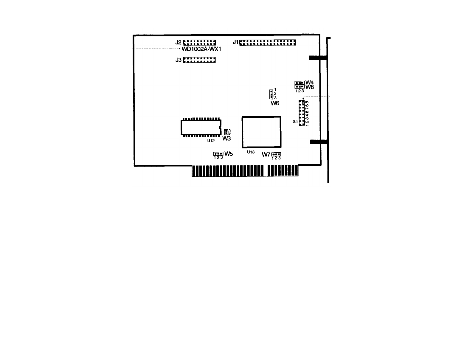
HDD Controller WD1002A-WX1 (8-bit)
Model number --------
-- Extra jumper
FACTORY SETTINGS
Jumper
W1
W2
W3
W4
W5
W6
W7
W8
* No jumper pins - 1 and 2 are connected by a PCB board etch.
Position
N/A
N/A
1 to 2
2 to 3
* hard-wired 1 to 2
2 to 3
* hard-wired 1 to 2
2 to 3
Description
Not used.
Not used.
BIOS ROM is enabled (on controller).
Device address 320H.
BIOS ROM size (32K or 64K).
Reduced write current (< = 8 heads).
IRQ 5.
Disk controller I. D. (set to be the first).
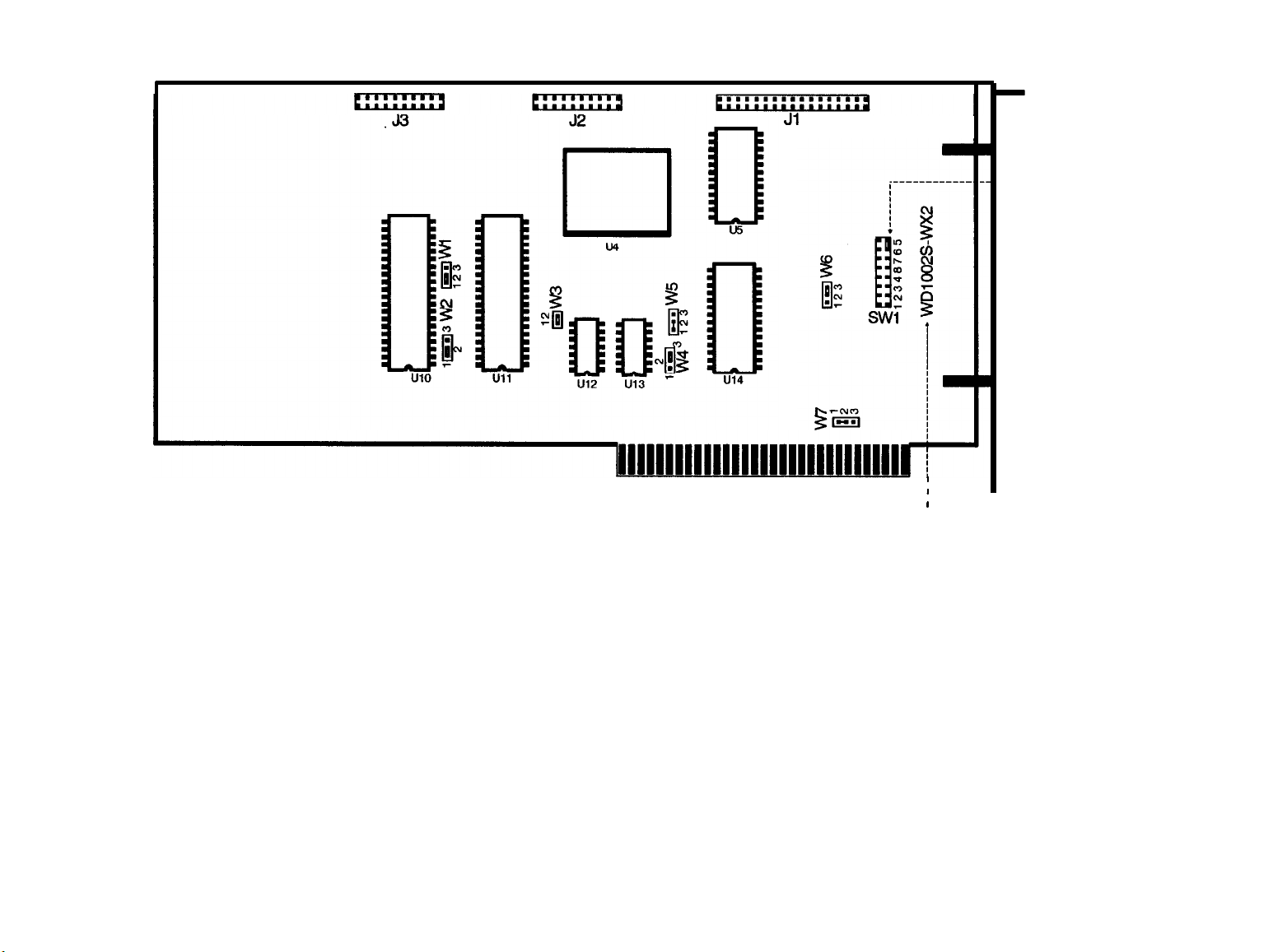
HDD Controller WD1002S-WX2 (8-bit)
Jl
I
I
FACTORY SETTINGS
Jumper
Model number--j
Position Description
0
‘--Extra jumper
W1
W-2
W3
W4
W5
W6
W7
* No jumper pins - 1 and 2 are connected by a PCB board etch.
1 to 2
1 to 2
1 to 2
2 to 3
* hard-wired 1 to 2
2 to 3
* hard-wired 1 to 2
Required for this configuration.
Required for this configuration.
BIOS ROM is enabled (on controller).
Device address 320H.
BIOS ROM size (32K or 64K).
Reduced write current (< = 8 heads).
IRQ 5.
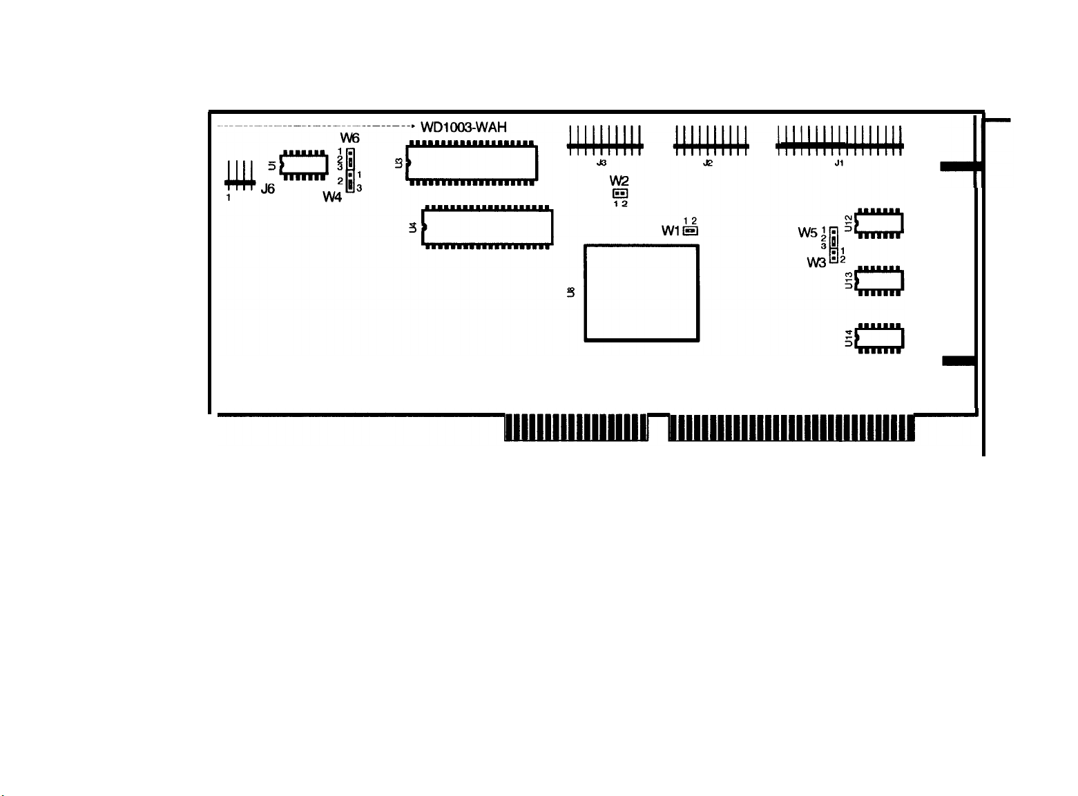
HDD Controller WD1003-WAH (16-bit)
Model number
FACTORY SETTINGS
Jumper Position
W1
W2
W3
W4
W5
W6
* No jumper pins.
1 to 2
No jumper
* No jumper
2 to 3
2 to 3
2 to 3
Description
Status read is latched.
Primary address selected.
Required for this configuration.
Required for this configuration.
Standard configuration.
Standard configuration.
Connection of LED indicator cable :
Model
Equity III
Equity II +
Equity III +
Pin 1 of J6
Orange wire
Blue wire
Red wire
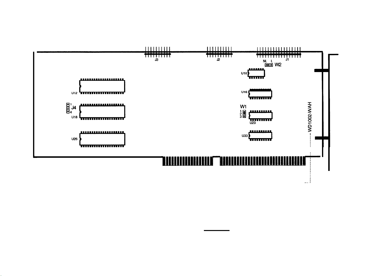
HDD Controller WD1002-WAH (16-bit)
FACTORY SETTINGS
Jumper
W1 1 to 2
W2
Position
Center to NL
Connection of LED indicator cable :
Description
Primary base address.
HDD activity LED only lights when the controller accesses the drive.
Model Pin 1 of J4
Equity III Orange wire
Equity II +
Equity III +
Blue wire
Red wire
Model number -~
j
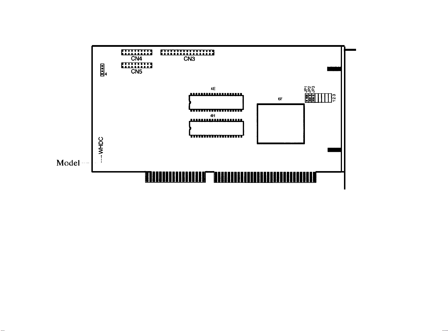
HDD Controller WHDC (16-bit)
CN6
n
l
:
-4
0
FACTORY SETTINGS
Jumper
* JP1 (J1) *2 to 3 (B to C)
* JP2 (J2)
* JP3 (J3) * 1 to 2 (A to B)
JP4 to JP8
* “JP” may labeled as “J”,
Position
* 1 to 2 (A to B) Status read is non-latched (select = drive busy).
No jumper pins.
Description
Primary address selected.
WAH mode (dual HDD controller).
Hardwired to factory settings.
“1” as “A”, “2” as “B” and “3” as “C”.
Connection of LED indicator cable :
Model Pin 1 of CN6
Equity III
Equity I I +
Equity I I I + Red wire
Orange wire
Blue wire
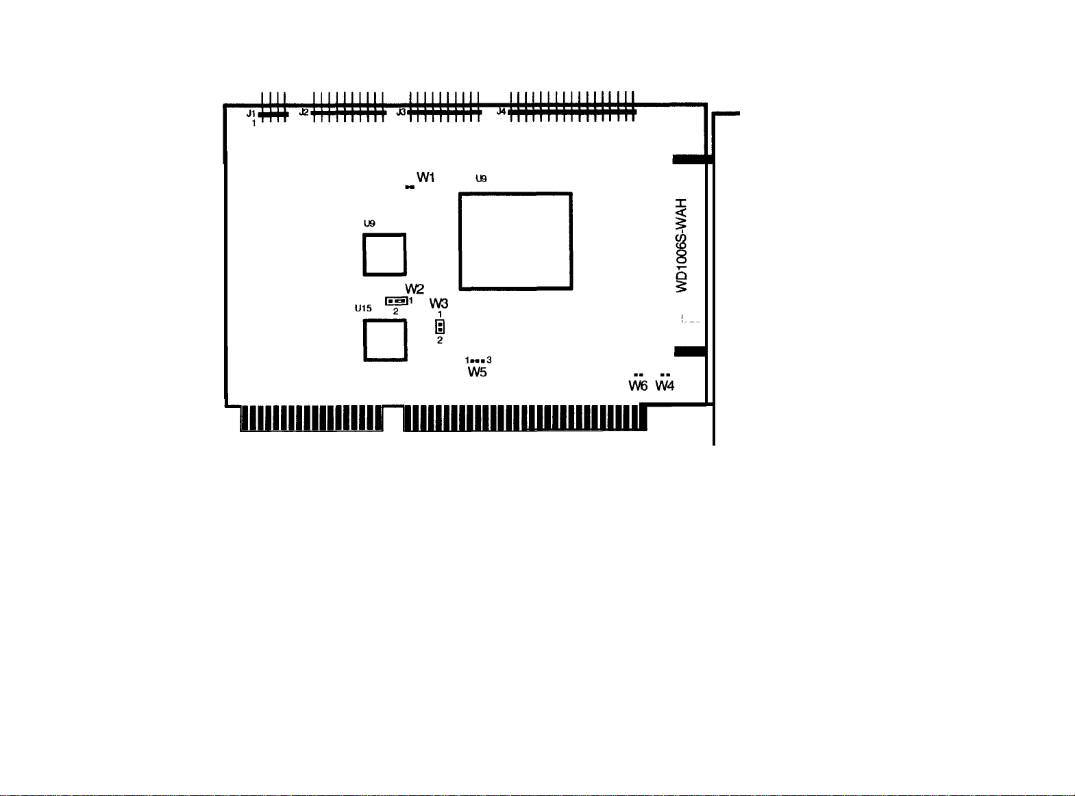
HDD Controller WD1006S-WAH (16-bit)
Model number
FACTORY SETTINGS
Jumper
W1
W2
W3
W4
W5
W6
* No jumper pins.
Position
* 1 to 2
1 to 2
No jumper
* No jumper
* 1 to 2
* No jumper
Description
LED lights for drive selection (non- latched).
No reduced write current,
Enables cacheing.
Isolates mounting bracket from logic ground.
Primary controller port.
Non-latched mode.
Connection of LED indicator cable :
Model
Equity 386/20
Pin 1 of J1
Red wire
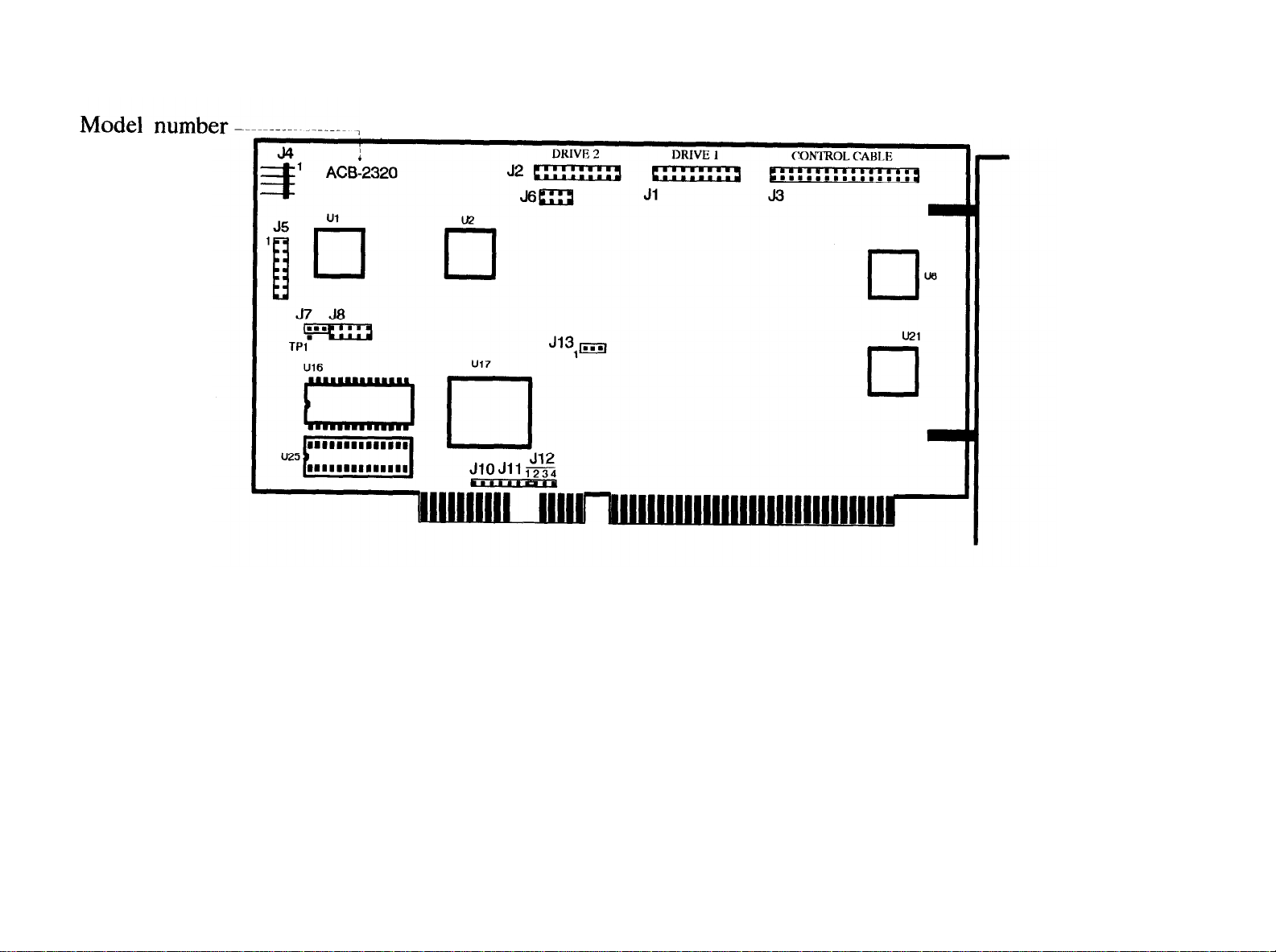
HDD Controller ACB-2320 (16-bit)
FACTORY SETTINGS
Jumper
J5
J6
J7
J8
J9, J10, J11
J12
J13
Position
No jumpers
No jumpers
No jumper
No jumpers
No jumpers
1 to 2
No jumper
Description
Used for hardware port addressing.
Manufacturing test points (DO NOT JUMPER).
Serial monitor output (DO NOT JUMPER).
Manufacturing test points (DO NOT JUMPER).
Not used.
Selects IRQ 14.
ACB-BIOS disabled (no ROM present in location U25).
Connection of LED
Model
Equity 386/20
indicator cable :
Pin 1 of J4
Red wire
EPSON AMERICA, INC.
SERVICE
PRODUCT SUPPORT BULLETIN
PSB NO. : S-0068 DATE:
SUBJECT: EQUITY I,
This bulletin describes the jumper locations and settings
on the Equity I MRS board and Equity
configuring the computers for third party keyboards and for
enabling an 8087 math coprocessor.
various releases of the Equity
that each version supported.
The Equity
change system configuration, are also provided.
Equity I MRS Board jumpers........................Page 2
Equity
III
main board dip switch settings, to set up or
II
MCY Board P/N Y1442071000 Rev. OO.......Page 3
1/25/89
II AND III MAIN BOARD JUMPER CONFIGURATIONS
ORIGINATOR: RE
II
MCY boards and the features
Index
II
MCY board used for
It also describes the
PAGE: 1 of 6
Equity
Equity
Equity
Equity
Equity
II
MCY Board P/N Y1442071000 Rev. O1.......Page 4
II
MCY Board P/N Y1442071000 Rev. O2.......Page 4
II
MCY Board P/N Y1442075000 . . . . . . . . . . . . ..Page 5
II
MCY Board P/N Y1442076000 . . . . . . . . . . . . ..Page 5
III
Main Board Dip-switch configuration....Page 6
EPSON AMERICA SERVICE, 23610 TEL0 AVENUE, TORRANCE, CALIF. 90505
 Loading...