

Page 1

®
EPSON
EQUITY® 386/33 PLUS
User’s Guide
Page 2

IMPORTANT NOTICE
DISCLAIMER OF WARRANTY
Epson America makes no representations or warranties, either express or implied, by or
with respect to anything in this manual, and shall not be liable for any implied warranties
of merchantability and fitness for a particular purpose or for any indirect, special, or
consequential damages. Some states do not allow the exclusion of incidental or
consequential damages, so this exclusion may not apply to you
COPYRIGHT NOTICE
All rights reserved. No part of this publication may be reproduced, stored in a retrieval
system, or transmitted, in any form or by any means, electronic, mechanical,
photocopying, recording, or otherwise, without the prior written permission of Epson
America, Inc. No patent liability is assumed with respect to the use of information
contained herein. Nor is any liability assumed for damages resulting from the use of the
information contained herein. Further, this publication and features described herein are
subject to change without notice.
TRADEMARKS
Epson is a registered trademark of Seiko Epson Corporation
Equity is a registered trademark of Epson America, Inc.
General notice: Other product names used herein are for identification purposes only and
may be trademarks of their respective companies.
Copyright 0 1992 by Epson America, Inc.
Torrance, California
ii
Y74499100100
Page 3

Important Safety Instructions
1.
Read all of these instructions and save them for later reference.
2.
Follow all warnings and instructions marked on the product.
3.
Unplug this product from the wall outlet before cleaning. Use a
damp cloth for cleaning, not liquid cleaners or aerosol cleaners.
4.
Do not use this product near water.
Do not place this product on an unstable cart, stand, or table.
5.
Slots and openings in the cabinet and the back or bottom are
6.
provided for ventilation; these openings must not be blocked or
covered. This product should never be placed near or over a
radiator or heat register.
7.
This product should be operated from the type of power source
indicated on the marking label. If you are not sure of the type of
power available, consult your dealer or local power company.
8.
Connect all equipment to properly grounded (earthed) power
outlets. If you are unable to insert the plug into the outlet,
contact your electrician to replace your obsolete outlet. Avoid
using outlets on the same circuit as photocopiers or air control
systems that regularly switch on and off.
9.
Do not locate this product where the cord will be walked on.
10.
If an extension cord is used with this product, make sure that the
total of the ampere ratings on the products plugged into the
extension cord do not exceed the extension cord ampere rating.
Also, make sure that the total of all products plugged into the
wall outlet does not exceed 15 amperes.
11.
Never push objects of any kind into this product through the
cabinet slots. Never spill liquid of any kind on the product.
iii
Page 4

12.
Except as specifically explained in the User’s Guide, do not
attempt to service this product yourself. Refer all servicing to
qualified service personnel.
13. Unplug this product from the wall outlet and refer servicing to
qualified service personnel under the following conditions:
A. When the power cord or plug is damaged.
B.
If liquid has entered the product.
C.
If the product does not operate normally when the operating
instructions are followed. Adjust only those controls that are
covered by the operating instructions, since improper
adjustment of other controls may result in damage and will
often require extensive work by a qualified technician to
restore the product to normal operation.
D. If the product has been dropped or the cabinet has been
damaged.
E.
If the product exhibits a distinct change in performance.
iv
Page 5

Contents
Introduction
Where to Get Help . . . . . . . . . . . . . . . . . . . . . . . . . . 2
Chapter 1
Copying the Reference and Utility Files
Special Keys on the Keyboard
Stopping a Command or Program
Resetting the Computer
Using a Power-on Password
Using Disks and Disk Drives
How Disks Store Data
Types of Diskette Drives
Caring for Diskettes and Diskette Drives
Write-protecting Diskettes
Using a Single Diskette Drive System
Inserting and Removing Diskettes
Formatting Diskettes
Making Backup Copies
Using a Hard Disk Drive
Chapter 2
Using AUTOEXEC.BAT and Other Batch Files
Changing the Processor Speed
Entering Keyboard Commands
Using the ESPEED Program
Using Your Computer as a Network Server
Using a Password in Network Server Mode
Using Special VGA Features
Using Your Computer
..............
...................
.................
.......................
....................
....................
.....................
...................
..........
..................
............
..............
......................
....................
...................
Enhancing System Operations
..........
...................
...............
.................
...........
........
....................
1-1
1-2
1-4
1-4
1-6
1-7
1-7
1-9
1-12
1-14
1-16
1-17
1-19
1-19
1-20
2-1
2-2
2-4
2-5
2-7
2-8
2-9
vii
Page 6

Chapter 3
Accessing Internal Components
Removing the Cover
Removing the Subassembly
Replacing the Subassembly
Replacing the Cover
Chapter 4
lnstalling and Removing Options
Main System Board
Changing the Jumper Settings
Setting the Jumpers
Replacing the Battery
Installing an Option Card
Removing an Option Card
Using the Alternate VGA Interface
Adding Memory Modules
Installing Memory Modules
Removing Memory Modules
Installing a Math Coprocessor
Removing a Math Coprocessor
Post-installation Setup for Memory Cards
Using the CORFIX Program
Post-installation Setup
.........................
.....................
.....................
..........................
..........................
....................
.......................
.........................
......................
......................
.................
......................
..................
.................
....................
...................
.............
..................
........................
3-2
3-5
3-9
3-17
4-3
4-4
4-4
4-7
4-11
4-15
4-16
4-18
4-19
4-22
4-23
4-26
4-26
4-27
4-28
Chapter 5
Choosing the Correct Drive Bay
How to Use This Chapter
Setting the Hard Disk Drive Jumpers
Changing the Jumper Settings
Installing a Hard Disk in the Vertical Position
Installing and Removing Drives
...................
.......................
................
.................
...........
Removing the Mounting Frames From the Drive
Removing and Attaching the Mounting Plate
Installing the Drive
.......................
Removing a Hard Disk From the Vertical Position
viii
........
........
......
5-2
5-3
5-4
5-5
5-7
5-8
5-10
5-11
5-17
Page 7

Installing or Removing a Drive in the Horizontal Position . . .
Installing a Drive in the Horizontal Position . . . . . . . .
5-19
5-19
Removing a Drive From the HorizontaI Position . . . . . 5-26
Appendix A Specifications
CPU and Memory
Controllers
Interfaces
...........................
............................
Power Supply.
Mass Storage
Keyboard
............................
Environmental Requirements
Physical Characteristics
System Memory Map
Appendix B
Performing System Diagnostics
Starting the Diagnostics Program
The Main Menu Screen
Setting the Run Time Parameters.
Error Logging.
Selecting Diagnostic Tests
Selecting Multiple Tests
Running the Tests
Memory Diagnostics
Hard Disk Diagnostics.
Hard Disk Parameters
Hard Disk Format
Media Analysis
Performance Test
Seek Test
............................
Read/Verity Test
Check Test Cylinder
Force Bad Tracks
Hard Disk Error Messages
.......................
.........................
..........................
................
....................
.....................
.................
.......................
.................
.........................
......................
....................
..........................
.........................
.......................
.....................
.......................
.........................
........................
........................
......................
........................
..................
A-1
A-2
A-2
A-3
A-3
A-4
A-4
A-4
A-5
B-2
B-2
B-4
B-6
B-8
B-8
B-10
B-12
B-13
B-14
B-17
B-18
B-18
B-18
B-19
B-19
B-19
B-19
ix
Page 8

Floppy Disk Diagnostics
Performing the Tests
......................
.....................
Floppy Disk Error Messages
Miscellaneous Diagnostics
Printer Adapter Test.
.....................
.....................
Communication Adapter Test
Exiting System Diagnostics
Appendix C Troubleshooting
.....................
.................
................
B-20
B-21
B-22
B-23
B-23
B-24
B-25
Identifying Your System
Error Messages
............................
The Computer Won’t Start
The Computer Does Not Respond
Password Problems
......................
.....................
.................
.........................
Accessing Your Current Password
Keyboard Problems
Monitor Problems
Diskette Problems
Diskette Drive Problems
Hard Disk Problems
Installing the Drive
Preparing the Drive
Accessing Data on the Drive
Software Problems
Printer Problems
Option Card Problems
Mouse Problems
Memory Module Problems
Battery Problems
Math Coprocessor Problems
Glossary
.........................
..........................
..........................
......................
.........................
......................
......................
.................
..........................
...........................
.......................
...........................
.....................
...........................
....................
.............
C-1
C-2
C-5
C-6
C-8
C-8
C-10
C-10
C-12
C-14
C-15
C-16
C-17
C-18
C-18
C-20
C-21
C-22
C-23
C-23
C-24
Index
x
Page 9

Introduction
This
Equity® 386/33 PLUS User’s Guide
you need to get the best results from your computer. You’ll find
instructions for adding options to your system such as disk
drives, option cards, or a math coprocessor, as well as general
reference information such as how to use diskettes, test your
system, and troubleshoot minor problems.
Note
For instructions on setting up your system or changing the
SETUP configuration, see the Setup Guide.
You don’t have to read everything in this book. Its contents are
summarized below:
Chapter 1 covers general operating procedures, such as using
and caring for disks and disk drives.
Chapter 2 describes special features you can use to enhance
your system’s performance.
contains the information
Chapter 3 tells how to remove and replace the computer’s
cover and subassembly to reach internal components.
Chapter 4 describes some of the options you can use in your
computer and instructions for setting jumpers, replacing the
battery, and installing options.
Chapter 5 explains how to install and remove disk drives.
Appendix A lists the specifications of your computer,
Appendix B covers the system diagnostic tests you can run, and
Appendix C contains troubleshooting tips.
At the end of this manual you’ll find a glossary and an index.
Introduction 1
Page 10

Where to Get Help
If you purchased your computer in the United States, Epson
America provides local customer support and service through a
nationwide network of authorized Epson dealers and Service
Centers.
Epson also provides the following support services through the
Epson Customer Resource Center at (800) 922-8911:
cl
Technical assistance with the installation, configuration,
and operation of Epson products
cl
Assistance in locating your nearest Authorized Epson
Reseller or Service Center
Ll
Sales of ribbons, supplies, parts, documentation, and
accessories for your Epson product
cl
Customer Relations
cl
Epson technical information library fax service
Q
Product literature with technical specifications on our
current and new products.
If you purchased your computer outside of the United States,
please contact your dealer or the marketing location nearest
you for customer support and service. International marketing
locations are listed on the inside back cover.
2 Introduction
Page 11

Chapter 1
Using Your Computer
This chapter briefly describes the following procedures for
using your computer:
Q
Copying the Reference and Utility diskette files
CI
Using special keys on the keyboard
LI
Stopping a command or program
0
Resetting the computer
Q
Using a password
0
Using disks and disk drives
LI
Preparing a hard disk for moving.
These instructions assume you have already installed the
operating system on your computer according to the
instructions in your operating system manuals.
Copying the Reference and Utility Files
If you have a hard disk, you’ll probably want to copy some of
the files on your Reference and Utility diskettes to the hard disk
for convenience. This allows you to run the programs any time
without having to insert a diskette. Copy the following files
from the Reference diskette to your hard disk:
CORFIX.EXE HDSIT.COM
ESPEED.EXE
(Chapter 2 and Appendix B explain how to use these programs.)
HDSIT.VER
Using Your Computer
1-1
Page 12
The Reference diskette also contains files for the System
diagnostics program. Because you should always run this
program from the Reference diskette, do not copy these files to
your hard disk.
The Utility diskettes contain VGA drivers that allow you to
display graphics in certain high-resolution modes. If you want
to use any of these extended modes on your VGA monitor,
copy any VGA files you need to your hard disk. See the
VGA Utilities Guide
for instructions.
Note
Be sure to make backup copies of your Reference and Utility
diskettes.
Special Keys on the Keyboard
Certain keys on your keyboard serve special functions when
your computer is running your operating system or application
programs, as described in the table below.
Special key functions
Key
GEI
1-2
Using Your Computer
Purpose
Moves the cursor one tab to the right in normal
mode and one tab to the left in Shift mode.
Changes the letter keys from lower- to uppercase;
changes back to lowercase when pressed again.
The numeric/symbol keys on the top row of the
keyboard and the symbol keys in the main part of
the keyboard are not affected.
Produces uppercase characters or the top
symbols on the keys when used with the main
character keys. Produces lowercase characters
when the Caps Lock function is on.
Page 13

Special key functions (continued)
Key
[wl
[ul
m
Iml
@iEl
[Erj
m-m
Purpose
Works with other keys to perform special (control)
functions, such as editing operations in MS-DOS
and various application programs.
Works with other keys to enter alternate character
codes or functions.
Moves the cursor back one space, deleting the
character to the left of the cursor.
Ends a line of keyboard input or executes a
command.
Turns the Insert function on and off.
Deletes the character marked by the cursor.
Control cursor location.
Changes the function of the numeric/cursor keys
from entering numbers to positioning the cursor;
changes back when pressed again.
Cancels the current command line or operation.
Perform special functions within application
programs.
@gg (PrtSc)
[slsl (Req)
m
[pul
Prints the screen display on a printer.
Generates the System Request function in some
application programs (used with
Controls scrolling in some applications.
Suspends the current operation.
Terminates the current operation (when used with
Lctrl.
Using Your Computer
[ul).
1-3
Page 14

The
[Qpllodrl, [=I,
the key once to turn on a function and again to turn it off.
When the function is enabled, the corresponding light in the
upper right comer of the keyboard is on.
and
[s#d]
keys work as toggles; press
Stopping a Command or Program
You may sometimes need to stop a command or program while
it is running. If you have entered an MS-DOS command that
you want to stop, try one of the following commands:
0
Hold down the
CI
Hold down the
These methods may also work in your application program. If
not, you may need to reset the computer as described below.
Caution
Do not turn off the computer to stop a program or command
because the computer erases any data you did not save.
[cbll
key and press
[cbll
key and press
[cl
m.
Resetting the Computer
Occasionally, you may want to clear the computer’s current
settings or its memory without turning it off. You can do this
by resetting the computer.
For example, if an error occurs and the computer does not
respond to your keyboard entries, you can reset it to reload
your operating system and try again. However, resetting erases
any data in memory that you have not saved; so reset only if
necessary.
1-4
Using Your Computer
Page 15

Caution
Do not reset the computer as a means to exit a program.
Some programs classify and store new data when you exit
them in the normal manner. If you reset the computer
without properly exiting a program, you may lose data.
To reset the computer, the operating system must be either on
the hard disk or on a diskette in drive A; so if you do not have a
hard disk, insert the system diskette in drive A.
There are two ways to reset the computer:
0
If you are using
press thecdDCW
MS-DOS, hold down a and
m
and
key. The screen goes blank for a moment
and then the computer should reload MS-DOS. If it doesn’t,
try the next method.
0
Press the
RESET
button on the front panel. This method
works even when the computer does not respond to your
keyboard entries.
If resetting the computer does not correct the problem, you
probably need to turn it off and reboot it. Remove any
diskette(s) from the diskette drive(s). Turn off the computer
and wait five seconds. If you do not have a hard disk, insert the
system diskette in drive A. Then turn on the computer.
Using Your Computer
1-5
Page 16

Using a Power-on Password
If you set a power-on password when you ran the SETUP
program, you must enter it every time you turn on or reset the
computer. Follow these steps to use your password:
1.
If you do not have a hard disk, insert your system diskette in
drive A.
2.
Turn on the computer or press
completes its memory test, the screen displays the
following prompt:
Enter Password :
3.
Type your password at the prompt. The screen does not
display the characters you type. Then press
After you type the password correctly and press I, you see
the
Press <Del> to start SETUP prompt.
press
m,
the computer loads your operating system and
displays the command prompt.
If
you do not enter the correct password the first time, press
EM
and try again.
c5
RESET.
After the computer
[Entwl.
If you do not
Note
If you turned on network server mode when you ran the
SETUP program, see “Using Your Computer as a Network
Server” in Chapter 2 for instructions on using the power-on
password.
If you want to change or delete your current password,
you must run the SETUP program. See Chapter 2 of the
Setup
Guide
for instructions. If you do not know the correct
password, see “Password Problems” in Appendix C.
1-6
Using Your Computer
Page 17

Using Disks and Disk Drives
The disk drives in your computer allow you to store data on
disk, and then retrieve and use your stored data. This section
explains how disks work and tells you how to:
Use different types of diskettes and diskette drives
Care for your diskettes and diskette drives
Write-protect diskettes
Use a single diskette drive system
Insert and remove diskettes
Format diskettes
Make backup copies
Use a hard disk drive.
How Disks Store Data
Diskettes are made of flexible plastic coated with magnetic
material. This plastic is enclosed in a square jacket that is either
slightly flexible (5¼-inch diskette) or hard (3½-inch diskette).
Unlike a diskette, a hard disk is rigid and fixed in place. It is
sealed in a protective case to keep it free of dust and dirt. A
hard disk stores data the same way that a diskette does, but it
works much faster and has a much larger storage capacity.
All disks are divided into data storage compartments by sides,
tracks, and sectors. Double-sided diskettes store data on both
sides. On each side are concentric rings, called tracks, on which
a disk can store data.
Using Your Computer
1-7
Page 18
A disk is further divided by sectors, which can be visualized as
pie slices. The figure below provides a simple representation of
tracks and sectors.
Double-sided, double-density diskettes have either 40 or 80
tracks on each side, and double-sided, high-density diskettes
have 80 tracks on each side. Diskettes can have 8,9,15, or 18
sectors per track.
A hard disk consists of two or more platters stacked on top of
one another and thus has four or more sides. In addition, a hard
disk has many more tracks per side than a diskette, but the
number of tracks depends on the capacity of the hard disk. The
number of sectors depends on the type of hard disk.
1-8
Using Your Computer
Page 19
Your computer uses the read/write heads in a disk drive to
store and retrieve data on a disk. To write to a disk, the
computer spins it in the drive to position the disk so that the
area where the data is to be written is under the read/write
head. A diskette has an exposed area where the read/write
head can access it.
Because data is stored magnetically, you can retrieve it, record
over it, and erase it just as you play, record, and erase music on
a cassette tape.
Types of Diskette Drives
The following list describes the four types of diskette drives
you can use in your computer and which diskettes to use with
them:
Q
1.44MB drive-Use 3½-inch, double-sided, highdensity,
135 TPI (tracks per inch), 1.44MB diskettes. These diskettes
contain 80 tracks per side, 18 sectors per track, and hold up
to 1.44MB of information (approximately 600 pages of text).
Note
MB stands for megabyte, which equals 1024KB (or
1,048,576 bytes). KB stands for kilobyte, which equals
1024 bytes. Each byte represents a single character, such
as A, $, or 3.
0
1.2MB drive-Use 5¼-inch, double-sided, high-density, 96
TPI, 1.2MB diskettes. These diskettes contain 80 tracks per
side, 15 sectors per track, and hold up to 1.2MB of
information (approximately 500 pages of text).
Using Your Computer
1-9
Page 20
0
720KB drive-Use 3½-inch, double-sided, doubledensity,
135 TPI, 720KB diskettes. These diskettes contain 80 tracks
per side, 9 sectors per track, and hold up to 720KB of
information (approximately 300 pages of text).
Cl
360KB drive-Use 5¼-inch, double-sided, doubledensity,
48 TPI, 360KB diskettes. (You can also use single-sided,
160KB or 180KB diskettes.) These diskettes contain 40
tracks per side and 8 or 9 sectors per track. With 8 sectors
per track, a diskette holds up to 320KB. With 9 sectors per
track, a diskette holds up to 360KB of information
(approximately 150 pages of text).
Note
You must format a new diskette before you can store data on
it. See “Formatting Diskettes,” later in this section.
Drive and diskette incompatibilities
If your computer has more than one type of diskette drive, or if
you use different types of diskettes, you need to be aware of
certain incompatibilities between the drives and diskettes.
Because of the type and size differences, you cannot use a
3M-inch diskette in a
5%inch
drive or vice versa. There are
also limitations on using diskettes that are the same size as the
drive but have different capacities. The following tables
summarize the possibilities and limitations.
1-10
Using Your Computer
Page 21

5¼-inch drive/diskette compatibility
Drive type
360KB
1.2MB 1.2MB, 360KB,* 320KB,* 180KB,* 160KB*
It you write to this diskette in a 1.2MB drive, you may not be able to read it
or write to it in a 360KB drive later.
3½-inch drive/diskette compatibility
Drive type
720KB 720KB
1.44MB 1.44MB, 720KB
Diskette types it can read from and write to
360KB, 320KB. 180KB. 160KB
Diskette types it can read from and write to
Because of these incompatibilities, always indicate the diskette
type and density when you label your diskettes. (Usually this
information appears on the manufacturer’s label.)
If you have any combination of the above drives (1.44 MB,
1.2MB, 720KB, or 360KB) and you are using MS-DOS, you can
copy files from one drive to another-using COPY or
XCOPY-as long as the correct diskette type is in each drive.
You can also use these commands to copy files between a hard
disk and
any type
of diskette. However, you cannot use the
MS-DOS DISKCOPY command to copy from one diskette drive
to another if the two drives are not the same type. For more
about copying files and diskettes, see your MS-DOS or other
operating system manuals.
Using Your Computer
1-11
Page 22

Caring for Diskettes and Diskette Drives
Follow these basic precautions to protect your diskettes and
avoid losing data:
a
If you have a diskette that contains data you don’t want to
accidentally write over or erase, be sure you write-protect
it. This is especially important for your operating system
and application program diskettes. See “Write-protecting
Diskettes,” below, for more details.
a
Do not remove a diskette from the diskette drive or reset or
turn off the computer while the drive light is on. This light
indicates that the computer is copying data to or from a
diskette. If you interrupt this process, you can destroy data.
cl
Remove all diskettes before you turn off the computer.
a
Keep diskettes away from dust and dirt. Small particles of
dust or dirt can scratch the magnetic surface, destroy data,
and ruin the read/write heads in a diskette drive.
a
Never wipe, brush, or try to clean diskettes in any way.
a
Keep diskettes in a moderate environment. Don’t leave
diskettes sitting in the sun or in extreme cold or heat.
1-12
a
Keep diskettes away from magnetic fields, such as electrical
appliances, telephones, and loudspeakers. (Diskettes store
information magnetically.)
a
Do not place diskettes on top of your monitor or near an
external hard disk drive.
cl
Always hold a
5%inch
diskette by its protective jacket and
never touch the magnetic surface (exposed by the
read/write slot). The oils on your fingertips can damage it.
Using
Your
Computer
Page 23

Q
Do not place anything on top of your diskettes, and be sure
they do not get bent.
D
Carefully label your diskettes and indicate the type and
density. Attach the label only along the top of a diskette
(next to the manufacturer’s label). Do not stick several
labels on top of one another; this can make it difficult to
insert and remove the diskette in the drive.
P
Write on a diskette label before you attach it to the diskette.
If you need to write on a label that is already on the
diskette, use only a soft-tip pen-not a ballpoint pen or a
pencil.
Q
Store diskettes in their protective envelopes and in a proper
location, such as a diskette container. Do not store diskettes
flat or stack them on top of each other.
Using Your Computer
1-13
Page 24
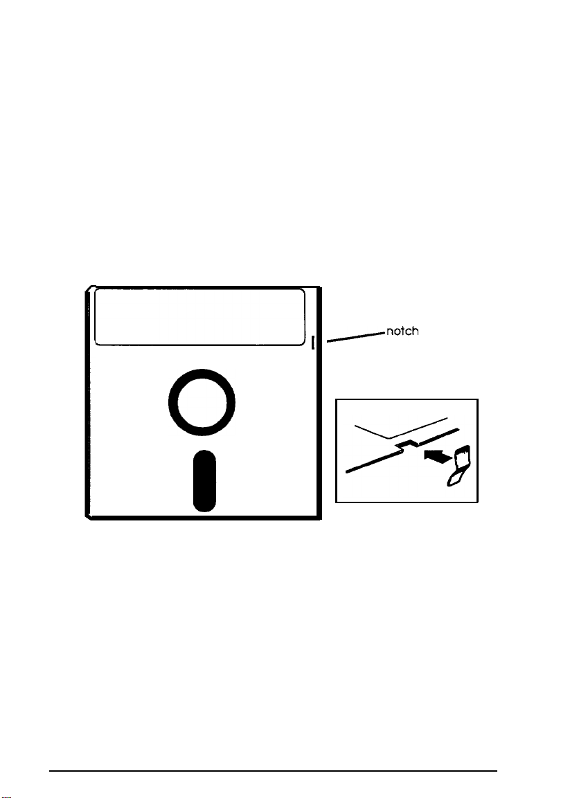
Write-protecting Diskettes
You can write-protect a diskette to prevent its data from being
altered. When a diskette is write-protected, you can read it and
copy data from it, but you cannot store new data on it or delete
any files it contains.
To write-protect a 5¼-inch diskette, cover the small,
rectangular notch (shown below) with an adhesive
write-protect tab. Write-protect tabs usually are included in a
new package of blank 5¼-inch diskettes.
+]I
-notch
l
0
To remove the write protection, peel off the write-protect tab.
1-14
Using Your Computer
Page 25
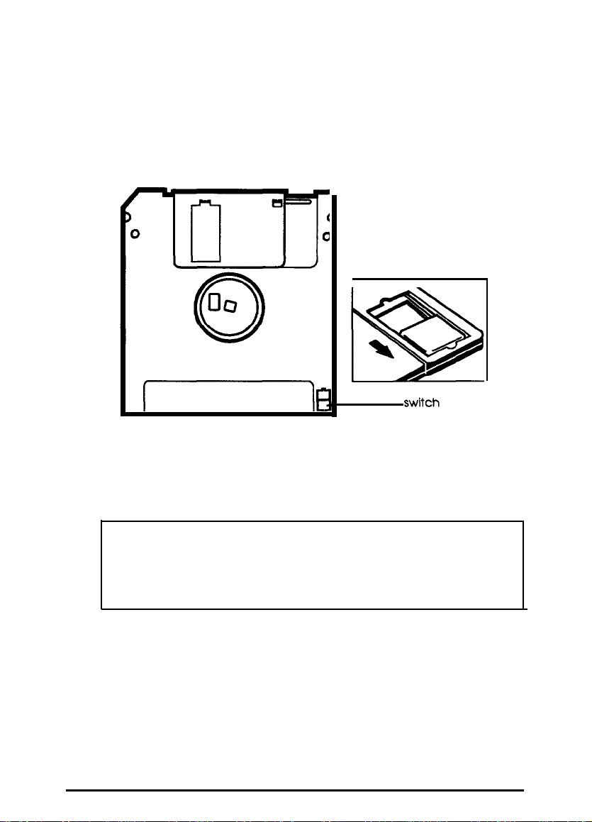
On a 3½-inch diskette, the write-protect device is a small
switch on the back of the diskette in the lower right corner,
shown below. To write-protect a 3½-inch diskette, slide the
switch toward the edge of the diskette until it clicks into
position, exposing a hole in the comer.
To remove the write protection, slide the switch toward the
center of the diskette until it clicks into position and the hole is
covered.
Note
Some program diskettes have no notch or switch so they are
permanently write-protected. This protects them from being
accidentally erased or altered.
Using Your Computer
1-15
Page 26

Using a Single Diskette Drive System
Most operating systems expect the computer to have at least
two diskette drives and display prompts and messages
accordingly. MS-DOS, for example, recognizes the first diskette
drive (the top drive) as drive A and a second diskette drive as
drive B. If you have only one diskette drive, MS-DOS can treat
it as both A and B when you need to perform operations that
normally require two diskette drives.
For example, if you enter a command to copy data from A to B,
MS-DOS copies the data from the first diskette you place in the
drive (which would be drive A) to the computer’s memory.
Then MS-DOS prompts you to insert another diskette (for drive
B) and copies the data from memory to the new diskette. When
copying is complete, you see a prompt to insert the original
diskette (A).
Because you may often swap diskettes this way, it is important
to remember which diskette is which. It is also a good idea to
write-protect your original diskette. See “Write-protecting
Diskettes,” above.
If you have a hard disk and one diskette drive, you can load the
operating system and application programs from the hard disk,
create and store your data there, and use the diskette drive just
for copying data to or from diskettes.
However, if you have only one diskette drive and no hard disk,
you need to use that drive to load the operating system as well
as any application program you are using. First, insert the
operating system diskette (the Startup diskette, for example) in
drive A and load the operating system; this copies it to the
computer’s memory (RAM) so you do not need to leave the
system diskette in the drive. Then remove the system diskette
and insert your application program diskette to load that data
into memory, too. See your application program manual for
detailed instructions.
1-16
Using Your Computer
Page 27

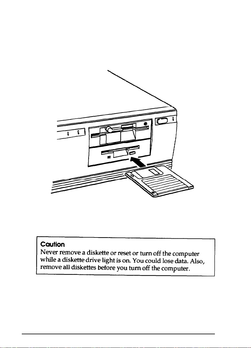
Inserting and Removing Diskettes
If you have a 5¼-inch diskette drive, insert a diskette as
follows: hold the diskette with the label facing up and the
read/write slot leading into the drive, as shown below.
Slide the diskette all the way into the slot. Then turn the latch
down to lock it in a vertical position. This keeps the diskette in
place and enables the read/write heads in the drive to access
the diskette.
When you want to remove a diskette, first make sure the disk
drive light is off. Then flip up the latch and carefully pull out
the diskette. Place it in its protective envelope and store it in a
proper location, such as a diskette container.
Using Your Computer
1-17
Page 28
If you have a 3½-inch diskette drive, insert the diskette with
the label facing up and the metal shutter leading into the
as
shown
in the following illustration. Slide the diskette into
drive,
the
drive until it clicks into place.
When you want to remove the diskette, make sure the drive
light is off; then press the release button. When the diskette
pops out, remove it and store it properly.
1-18
Using Your Computer
Page 29

Formatting Diskettes
Before you can store data on a new diskette, you must format it.
Formatting prepares the diskette so that the operating system
can write data on it. You need to do this only once, before you
use the diskette for the first time.
You can also reformat previously used diskettes to store new
data. This process erases all the data on the diskette, so be sure
you do not want to save any of the files on a used diskette
before you format it. See your operating system manual for
instructions on formatting diskettes.
Making Backup Copies
It is important to make copies of all your data and system
diskettes. Make backup (or working) copies of all diskettes that
contain programs, such as your operating system, Reference,
and Utility diskettes; then use only the copies. Store the original
diskettes away from your working diskettes. Also, copy your
data diskettes regularly, whenever you revise them, and store
them away from your originals.
If you have a hard disk, you’ll probably use it to store the
programs and data files you use regularly. Keep backup copies
of all your files on diskettes or tapes.
Using Your Computer
1-19
Page 30

Using a Hard Disk Drive
Using a hard disk is similar to using a diskette. However, the
hard disk provides several advantages:
a
A 40MB hard disk can store as much data as approximately
thirty-three 1.2MB diskettes, and a 100MB hard disk can
store as much data as approximately eighty-two 1.2MB
diskettes.
a
Your computer can perform all disk-related operations
faster.
a
You can store frequently used programs and data files on
the hard disk, eliminating the inconvenience of swapping
diskettes to access different files.
The added storage capacity makes it easy to move back and
forth between different programs and data files. However,
because it is so easy to add programs and files to your hard
disk, you may find yourself trying to organize hundreds of files.
Most operating systems let you keep related files together in
directories and subdirectories so they are easy to find and use.
See your operating system manual for instructions on
managing your files and directories.
1-20
Note
A hard disk must be partitioned and formatted before you
can use it. Be sure you have performed the procedures
described in your operating system manual to prepare your
hard disk for use.
Using Your Computer
Page 31

Backing up the hard disk
While the hard disk is very reliable, it is essential to back up
your hard disk files to diskettes or tapes in case you lose some
data accidentally. Make copies of alI your system and
application program diskettes before copying the programs to
the hard disk. After you create data files on the hard disk, be
sure to copy them whenever you revise them to keep your
backup diskettes or tapes up-to-date.
Caring for your hard disk
Follow these precautions to protect your hard disk drive from
damage and to avoid losing data:
Never turn off or reset the computer when the hard disk
access light is on. This light indicates that the computer is
copying data to or from the hard disk. If you interrupt this
process, you can lose data.
Never attempt to open the hard disk drive. The disk itself is
enclosed in a sealed container to protect it from dust.
Before you move your computer even a short distance, you
may need to run the HDSIT program to prepare the hard
disk for moving, as described below.
Preparing the hard disk for moving
If you need to move your computer to a new location, you may
want to run the HDSIT program provided on your Reference
diskette to protect the hard disk during the move.
HDSIT moves (or parks) the disk drive’s read/write heads to a
region on the disk surface that does not contain data, and locks
them securely in position. This protects the hard disk from
being damaged if the computer is bumped accidentally.
Using Your Computer
1-21
Page 32

Many hard disk drives, including all Epson drives,
automatically park their heads when you turn off the
computer. If your hard disk drive does not do this, or if you are
not sure that it does, be sure to run HDSIT.
Follow these steps to run HDSIT:
1.
If you copied the HDSIT.COM and HDSIT.VER files to your
hard disk, log onto the directory where they are stored. If
you did not copy the files to the hard disk, insert the
Reference diskette in drive A. Then type
@El
to log onto that drive.
2.
Type
HDSIT
and press
[Ent#I
A
: and press
You see a message on the screen that telIs you the disk drive’s
read/write heads will remain locked until you reset the
computer or turn the power off and on again. The computer
locks the heads and disables the keyboard. Remove any
diskettes and turn off the computer. You are now ready to
move it to the new location.
1-22
Using Your Computer
Page 33

Chapter 2
Enhancing System Operations
This chapter tells you how to use the following procedures to
enhance the operation of your computer:
Q
Using AUTOEXEC.BAT and other batch files
0
Changing the processor speed
0
Using your computer as a network server
0
Using special VGA features.
Using AUTOEXEC.BAT and Other Batch Files
If you are using MS-DOS to access your application programs,
you may find that there are commands you need to run
frequently. You can automate the execution of these commands
by listing them in a special file called a batch file. When you
type the name of the batch file and press
executes the commands in the file just as if you had typed each
command from the keyboard.
[Enbrl,
MS-DOS
If you have a word processing program that can save a file as a
text-only file (sometimes called an ASCII file), you can use it to
create a batch file. You can also use the MS-DOS COPY, EDIT,
or EDLIN command, or a text editor, to create the file.
One batch file that you may find particularly useful is called
AUTOEXEC.BAT. Every time you turn on your computer,
MS-DOS looks for the AUTOEXEC.BAT file and automatically
executes each of the commands in the file.
Enhancing System Operations
2-1
Page 34

When you install MS-DOS, it creates an AUTOEXEC.BAT file
for you, which you can modify or replace as described above.
Be sure to name the file AUTOEXEC.BAT and store it in the
root directory of the hard disk or diskette from which you load
MS-DOS.
See your MS-DOS manuals for more information about creating
and using batch files.
Changing the Processor Speed
Your computer’s processor can operate at two speeds: fast
(33 MHz) and slow (simulated 11 MHz). At fast speed, the
computer can access memory faster. This is the default setting
unless you change the speed to slow with SETUP or the
ESPEED program or set it to change automatically.
Note
When your computer is operating at fast speed, the
light on the front panel is on. It is off when the computer is
operating at slow speed.
TURBO
You should use fast speed for almost everything you do
because your programs will work faster. However, certain
application programs have specific timing requirements and
can run only at the slower speed. See your software manual to
determine if this is the case.
Some copy-protected programs require the computer to run at
slow speed while accessing the program on a diskette. These
programs also usually require you to leave a
that contains the copy protection-in the drive. If you use a
copy-protected program often, you may want to set your
processor speed to change automatically to slow speed when
accessing the diskette and return to fast when it is finished.
2-2
Enhancing System Operations
key
disk-the one
Page 35

Depending on the type of program you have, you may or may
not want to set the processor to auto speed. Follow these
guidelines:
0
If you are using a copy-protected program that can run
only on a diskette or that requires a key disk, try to load the
program at fast speed. If this works, you do not need to set
the speed to change automatically. If you can’t load the
program at fast, set the speed to change automatically.
Q
If you are using a copy-protected program that does not
require a key disk but requires a special procedure to install
it on a hard disk, set the speed to slow while you are
installing the program. Then set the speed to fast while you
load and run the program.
If this does not work, try installing
and
loading the program
at slow speed and then change to fast speed to run it. Do
not set the speed to change automatically.
There are three ways to change the processor speed:
0
Run the SETUP program
0
Enter a keyboard command
Q
Run the ESPEED program.
If you frequently use programs that require slow or automatic
speed, use SETUP to change the processor speed. See Chapter 2
of the
Setup Guide
for instructions.
If you use these programs only occasionally, you should use
the keyboard commands or the ESPEED program (described
below) to change the processor speed.
Enhancing System Operations
2-3
Page 36

Entering Keyboard Commands
You can change the processor speed by entering one of the
commands shown in the following table.
Speed setting commands
Numeric keypad commands Speed setting
33 MHz
I
I
To enter these commands, hold down the [key and the
[lutl
key simultaneously and then press the m or m key.
Use the
[+1
or
[-I
key on the numeric keypad.
Note
You can use the commands listed above while you are
running a program. However, if the program uses one of the
same commands for another function, you cannot use it to
change the processor speed. For example, if you are running
a program that uses the
the cursor, you cannot enter [m
[cbt [‘[:I
command to move
[Alt) 17
to change the
processor speed to slow. Another alternative is to use the
ESPEED program, described below.
The speed setting remains in effect until you press the
RESET
button or turn off the computer, or until you change it again
using the SETUP program, another keyboard command, or the
ESPEED program.
2-4
Enhancing System Operations
Page 37

Using the ESPEED Program
ESPEED provides an easy way to change the processor speed if
your application program does not recognize the
commands or if you want to include the program command in
a batch file.
The ESPEED program is provided on the Reference diskette. If
you copied this file onto your hard disk, log onto the drive
where it is stored. If you do not have a hard disk, insert your
Reference diskette in drive A and log onto drive A before you
enter the command to start the program.
[ctrll
key
For help information on how to run the ESPEED pro
the following at the command prompt and press
ESPEED ?
ram, type
EIW
d
:
You see this display:
Format: ESPEED
No Parm
F
S
?
:Displays current CPU Speed
:Set to Fast Speed
:Set to Slow Speed
:Help Message
[PISIP]
The message tells you the switches you should use to set the
speed to fast or slow. For example, to select slow speed, type
the following and press
ESPEED S
[Enl#l:
To change the processor speed back to fast, enter this command:
ESPEED F
Enhancing System Operations
2-5
Page 38

To display the current CPU speed, type ESPEED
m.
You see the following:
only
and press
<+>
33.0 MHZ
<->
<Esc> : Exit
To change the speed when
a
or $ key; then press & to exit.
: Speed Up
: Speed Down
you see this display, press the
The processor speed you set remains in effect until you change
it using the ESPEED program again, a keyboard command, or
the SETUP program; or until you press the
RESET
button or
turn off the computer.
Entering the ESPEED command in a batch file
You may want to run the ESPEED program by including the
command in a batch file. Let’s say you have a program called
SLOWDOWN which requires a slower processor speed. You
could include the following commands in a batch file to start
the SLOWDOWN program:
ESPEED S
SLOWDOWN
You could name the batch file SLOW.BAT. Whenever you
need
to run the SLOWDOWN program, insert the program diskette
in drive A. Then type SLOW and press
[Enbr).
The computer
changes the speed to slow and starts the SLOWDOWN
program.
See your operating system manuals for instructions on creating
and using batch files.
2-6
Enhancing System Operations
Page 39

Using Your Computer as a Network Server
A network sever is the master computer in a network and
provides storage space for the other computers connected to it.
It can also write files to and read files from the other computers.
Even if no one is typing commands at the network server
keyboard, the server can process commands sent to it from
other computers. If you use your computer as the network
server, you may want to prevent unauthorized users from
entering commands at the keyboard. To provide this security,
you can enable a power-on password in network server mode
using the SETUP program.
If you set a power-on password but do not turn on network
server mode, you enter the password before the computer loads
the operating system or the network software. Once you load it,
anyone can access your system by typing commands on the
keyboard. However, if you set a password and turn on network
server mode, you can load your operating system or network
software before you enter the password. This allows other
computers in the network to access the system, but prevents
unauthorized users from entering commands at your keyboard
and using any network server access privileges.
When you boot the computer in network server mode, you do
not see the password prompt ( _ ), as you would if network
server mode was turned off. The prompt is hidden to prevent
unauthorized users from knowing that a password is required.
You do not have to set a password in network server mode
to use your computer as a network server, but it is helpful.
See “Setting the Power-on Password” in Chapter 2 of the
Setup
Guide
for instructions on setting the password and
enabling network server mode. Then read the next section to
use your network password.
Enhancing System Operations
2-7
Page 40

Note
If your hard disk drive has a partition larger than 32MB and
you are using MS-DOS, you must use the MS-DOS SHARE
command to install file sharing and locking protection in a
network environment. See your MS-DOS manual for
instructions.
If you do not install SHARE, the following message flashes
on your screen after you install your network software and
reboot your computer:
WARNING! SHARE should be loaded
for
large media
Using a Password in Network Server Mode
When you turn on or reset the computer, it loads your
operating system or network software and you see either the
command prompt or the first screen displayed by your
network software.
Follow these steps to enter your password:
1.
Turn on or reset your computer. You do not see the password
prompt even though the computer is now waiting for you
to enter the correct password.
2.
Type your password and press I. The screen does not
display what you type.
Now you should be able to use your computer. Press a key
such as
you entered an incorrect password, the computer does not
respond. Type the correct password, press
the computer again.
m
to see if the keyboard accepts your command. If
Enlw, and try using
li
2-8
Enhancing System Operations
Page 41

Note
You cannot change or delete a power-on password in
network server mode. You must run SETUP and turn off
network server mode first. See Chapter 2 of the
for instructions. Then you can change or delete the password
as described in Chapter 1 of this manual.
Setup Guide
Using Special VGA Features
Your built-in VGA (video graphics array) display adapter
supports both standard VGA monitors and multifrequency
monitors with analog connectors. The VGA adapter operates in
all standard VGA resolutions without requiring any device
drivers. However, if you are using a monitor that supports
extended VGA features, you may want to use one or more of
the device drivers provided on the Utility diskettes.
If you are using your computer’s VGA feature connector and
Install VGA device drivers if you want to use these features:
0
Resolutions up to 800 x 600 or 1024 x 768 (non-interlaced) in
graphics modes with 16 colors
Q
Resolutions up to 640 x 480 in graphics modes with 256
colors
0
132-column text mode in 16 colors
CI
Graphics cursor movement performed by the built-in VGA
hardware.
Enhancing System Operations
2-9
Page 42

To use graphic display drivers in 800 x 600 or 1024 x 768
resolutions, you must have a multifrequency monitor capable
of displaying these resolutions. Standard VGA monitors cannot
display them.
You can use the VGA utilities (also provided on the Utility
diskettes) to take advantage of other special features of your
VGA adapter. Even if you do not use any device drivers, you
may want to install some of the VGA utilities. For complete
instructions on installing and using the VGA device drivers and
utilities,
see the VGA Utilities Guide.
2-10
Enhancing System Operations
Page 43

Chapter 3
Accessing Internal Components
To reach your computer’s internal components, you need to
remove the cover. In some cases, you may also need to remove
the front panel and the subassembly (the metal case that holds
the drive bays and the power supply). The instructions in this
chapter explain how to do these tasks:
Q
Remove and replace the cover
0
Remove and replace the subassembly.
Be sure to heed all the cautions and warnings so you do not
injure yourself or damage the computer. If you have any
reservations about performing these steps yourself, ask your
Epson dealer for assistance.
Note
You only remove the subassembly to access the math
coprocessor or SIMM sockets, or to install or remove a disk
drive. You do not need to remove it to install or remove an
option card.
Accessing Internal Components
3-1
Page 44

Removing the Cover
To access any internal components, you need to remove the
computer’s cover. Follow these steps:
1.
Turn off the computer and then any peripheral devices
(including the monitor and printer).
2.
Disconnect the computer’s power cable from the electrical
outlet and from the back panel. Also disconnect any cables
that are connected to the computer, including the keyboard
cable.
3.
If the monitor is on top of the computer, lift it off and set it to
one side.
4.
Turn the computer around so you are facing the back panel.
The cover is secured by a large screw on the back panel, as
shown below. Turn the screw counterclockwise to unlock
the cover.
3-2
Accessing Internal Components
Page 45

5.
The cover is also secured by two latches on the back, near the
comers. Press both latches inward and then lift up the cover
from the back panel. You might meet some resistance from
the grounding tabs along the inside of the cover.
6.
Pull the cover away from the front of the computer to
completely remove it. Then set it aside.
Accessing Internal Components
3-3
Page 46

7.
Before you touch any of the components, touch the inside of
the computer’s back panel, as shown below, to ground
yourself and avoid an electric shock.
3-4
WARNING
Be sure to ground yourself to the inside back panel of the
computer every time you remove the cover. If you are not
properly grounded, you could generate an electric shock
when you touch a component.
Accessing Internal Components
Page 47

Removing the Subassembly
You need to remove the subassembly to install or remove disk
drives, or to access the SIMM or math coprocessor sockets on
your computer’s main system board. The subassembly is the
large metal casing that holds the horizontal drive bays and the
power supply, as shown below.
Accessing Internal Components
3-5
Page 48

Follow these steps to remove the subassembly:
1.
Remove the front panel from the computer by gently
releasing the three tabs at the top of the panel and tilting it
toward you. You may want to use a flat-blade screwdriver
to release the tabs.
2.
If you have a hard disk drive, the drive cable is connected to
the main system board on the left side of the subassembly,
as shown below.
diskette drive
1
cable
3-6
hard disk
drive cable
Accessing internal Components
Page 49

Grasp the hard disk connector and pull it straight up to remove
it from the socket. Do not pull only on the cable.
3.
The diskette drive cable is connected to the socket above the
hard disk drive socket; disconnect it in the same manner.
4.
To lift the subassembly from the front of the computer, place
your thumbs under the diskette drive and raise the front of
the subassembly. (If there is a diskette drive installed in the
lower horizontal drive bay, place your thumbs underneath
that drive instead.)
Accessing
Internal Components
3-7
Page 50

5. Reach back underneath the subassembly and disconnect the
two power supply cables (labelled P4 and P5) connected to
the right side of the main system board, as shown below.
Pull each connector straight up. Do not pull only on the
cables.
power supply cable
3-8
6.
Lift the entire subassembly out of the computer and carefully
place it on your work surface.
Accessing Internal Components
Page 51

Replacing the Subassembly
Follow these steps to replace the subassembly:
1.
Notice that there are four mounting slots on the back of the
subassembly: two in the upper corners and two in the
lower comers.
Accessing Internal Components
3-9
Page 52

There are four corresponding tabs on the inside back panel
of the computer which fit into the subassembly slots.
tabs
Lift up the subassembly from your work surface and lower
the back end into the computer, guiding the tabs on the
computer into the top slots.
3-10
Accessing Internal Components
Page 53

2.
Hold up the front of the subassembly at a slight angle and
arrange the ribbon cables so they curve underneath the
subassembly and extend out its left side. Then grasp the
two power supply cables, labelled P4 and P5. Each
connector has six pin holes and a large tab on one side, as
shown below.
There is a 12-pin power supply socket on the right side of the
main system board (toward the back) that holds both of the
power supply connectors, as shown below.
power supply
Accessing Internal Components
3-11
Page 54

3. Position power supply connector P4 so the large tab on the
connector faces the right side of the computer. Beginning
with the six pins toward the back of the computer, carefully
line up the holes in the connector with the pins in the socket
and then push in the connector.
If you do not correctly align the holes with the pins in
the socket, you could severely damage your computer
4. Connect power supply connector P5 to the remaining six pins
in the socket using the same procedure.
3-12
Accessing Internal Components
Page 55

Carefully lower the front of the subassembly onto the
5.
computer. Make sure that all four tabs on the back of
computer are inserted into the slots on the subassembly.
the
Accessing Internal Components
3-13
Page 56

Guide the front of the subassembly over the opening in the
front of the computer so the two small tabs sit behind the
opening and the large tab with the curved lip extends over
the opening. If necessary, press on the large tab until the
subassembly snaps into place.
6.
Locate the hard disk drive and diskette drive ribbon cables.
(The hard disk drive cable is slightly wider than the
diskette drive cable.) Look at the back of each drive to make
sure you know which cable is which.
3-14
Accessing internal Components
Page 57

Both the diskette drive and hard disk drive sockets are
located on the main system board on the left side of the
subassembly, as shown below.
diskette drive
Both sockets have a notch on one side. As shown below, there is
a tab on one side of the connector. Connect the diskette
drive cable first.
tab
notch
Accessing Internal Components
3-15
Page 58

Align the connector with the socket so the tab on the
connector lines up with the notch in the socket. Make sure
the holes in the connector fit over all the pins in the socket
and then push in the connector.
align the holes with the pins, you
your computer when you push
7.
Now connect the hard disk drive cable in the same manner.
8.
To replace the front panel, fit the three ridged tabs on its
bottom edge into the three notches on the lower edge of the
computer, as shown below.
3-16
tabs
9.
Tilt up the front panel until the tabs on the top of the panel
touch the computer. Then push on the top of the panel until
it snaps into place.
Accessing Internal Components
Page 59

Replacing the Cover
Follow these steps to replace the computer’s cover:
1.
Facing the back of the computer, hold the cover so that the
side with three tabs on the edge faces away from you, as
shown below.
2.
Insert the three tabs into the three notches behind the front
panel of the computer.
Accessing Internal Components
3-17
Page 60

3.
Lower the cover onto the computer and press it down firmly
to form a tight seal.
4. Turn the large screw on the back panel clockwise to secure
the cover to the computer.
5. Reconnect the computer to the monitor, printer, keyboard,
and any other peripheral devices you have. Then reconnect
the power cable to the back of the computer and to an
electrical outlet.
3-18
Accessing Internal Components
Page 61

Chapter 4
Installing and Removing Options
You can enhance the performance of your computer by adding
a variety of options, including the following:
0
Option cards
Cl
Memory modules
LJ
A math coprocessor.
An option card is a circuit board you install in your computer
to add a particular function. Most option cards contain a
device, such as a modem, or provide an interface, such as a
high-resolution graphics card for a VGA monitor or a network
connector. This chapter describes how to install option cards
and configure your computer for use with them.
Memory module-also called SIMMs (single inline memory
modules)-allow you to increase the amount of memory in
your computer. If you want to install SIMMs, you may prefer to
ask your dealer to do it for you. You can, however, follow the
instructions in this chapter to install them yourself. This
chapter describes the SIMMs you can use in your computer.
Note
It is best not to expand your system’s memory by installing
an optional memory card. Using memory modules is more
efficient since you do not need to use one of your option
slots to add memory. Your computer can also access
memory installed on memory modules faster than memory
installed on a card.
installing and Removing Options
4-1
Page 62

A math coprocessor speeds up the numeric calculations your
computer performs when using certain application software. If
you purchase a math coprocessor, it is a good idea to ask your
dealer to install it for you, because it can be damaged easily. If
you decide to install it yourself, follow the appropriate steps in
this chapter.
This chapter also explains how to change the jumper settings
inside the computer. You may need to change jumper settings if
you install certain types of options or if you want to change the
way your computer operates.
If you need to replace the battery for your computer’s real-time
clock and CMOS RAM, you can follow the instructions in this
chapter.
To change jumper settings, replace the battery, or install the
options mentioned above, you must remove the computer’s
cover and you may need to remove the subassembly. See
Chapter 3 for instructions. (You do not need to remove the
subassembly to install or remove option cards.)
4-2
Installing and Removing Options
Page 63

Main System Board
As you follow the instructions in this chapter and Chapter 5,
use the illustration below to locate the necessary components
on your main system board.
alternate
VGA
diskette
drive
connector
hard disk
drive
connector
oprlon slofs
--_-II-,
interface
---ial
rt
-y
0
00
n
keyboard
I
power
supply
connectors
n
iicroprocessbr
‘math
I
I
battery socket
socket
(CN1)
coprocessor
Installing and Removing Options
SIMM
sockets
LED
connector
4-3
Page 64

Changing the Jumper Settings
A jumper is a small electrical connector that controls one of the
computer’s functions. The jumper settings in your computer
are preset at the factory; however, you can alter the following
functions by changing the standard settings:
0
Enable or disable the built-in VGA display adapter
Ll
Enable or disable the built-in mouse connector
D
Enable or disable the password function
D
Set the computer to use a color or monochrome monitor.
If you need to change any jumper settings, follow the
instructions in this section.
Setting the Jumpers
The illustration below shows the locations of the jumpers on
your computer’s main system board.
4-4
Installing and Removing Options
Page 65

A jumper’s setting is determined by where the jumper is placed
on the pins. It connects either pin A and the middle pin
(position A) or pin B and the middle pin (position B), as shown
below.
position B
@B
A
@I3
position A
@B
A
To move a jumper from one position to the other, use
needle-nose pliers or tweezers to pull it off its pins and gently
move it to the desired position.
Caution
Be careful not to bend the jumper pins or damage any
surrounding components on the main system board.
Installing and Removing Options
4-5
Page 66

The following table lists the jumper settings and their functions.
Main system
Jumper
number
J1
J2
J3
J4 A* A color monitor is installed
l
Factory setting
board
Jumper
setting Function
jumper settings
A’
B
A’
B
A
B* Enables the password function
B
Enables the built-in VGA display adapter
Disables the built-in VGA display adapter so
you can use a display adapter on an option
card In your computer as your primary
adapter
Enables the buitt-in mouse connector
Disables the built-in mouse connector so you
can use a mouse or other pointing device
connected to a port on an option card in
your computer
Disables the password function
A monochrome monitor is installed
If you need to change any jumper settings, follow these steps:
4-6
1.
Remove the computer’s cover as described in Chapter 3.
2.
Remove any option cards that may be blocking your access
to the jumpers. See page 4-15 for instructions.
3.
Change the jumper settings.
4.
Replace any option cards you removed. See “Installing an
Option Card” on page 4-11.
Follow the instructions in Chapter 3 to replace the
5.
computer’s cover.
Installing and Removing
Options
Page 67

Replacing the Battery
Your computer comes with a 3.6 volt lithium battery that
provides power for the real-time clock and the CMOS RAM.
The real-time clock keeps track of the time for your computer,
and the CMOS RAM stores the information about your system
configuration that was saved by the SETUP program.
This battery lasts approximately three to five years. If it loses
power, you will see an error message when you turn on or reset
your computer.
battery or to install the new battery for you. If you want to
replace the battery yourself, you can follow the instructions in
this section.
Note
When the battery runs out, your computer loses the
information stored in the CMOS RAM and the time stored in
the real-time clock. After you replace the battery, run the
SETUP program as described in the Setup
reconfigure your system and set the real-time clock.
Contact
your dealer to obtain a replacement
Guide
to
Installing and Removing Options
4-7
Page 68

Follow these steps to replace the battery:
1.
Remove the computer’s cover as described in Chapter 3.
2.
The battery is attached to the bottom of the computer case,
just behind the front panel, as shown below.
battery
To disconnect the battery from the main system board,
pull up the connector plugged into socket CN1, as shown
below.
4-8
connector
Installing and Removing Options
Page 69

3. The battery is attached to the computer with Velcro.@
Remove the battery by pulling it up from the bottom of the
computer case, as shown below. Then set it aside.
4. Remove the new battery from its package and position it so
the Velcro faces down and the cable faces connector CN1.
Then attach it to the bottom of the computer case, as shown
below.
Installing and Removing Options
4-9
Page 70

5.
Connect the battery cable to connector CN1.
battery
cable
connector
CN1
6.
Follow the steps in Chapter 3 to replace the computer’s cover.
Then run the SETUP program to reconfigure your system
and reset the time for the real-time clock. See Chapter 2 of
the Setup Guide for instructions.
4-10
Installing and Removing Options
Page 71

Installing an Option Card
Your computer has four standard option slots: three 16-bit slots
and one 8-bit slot. Each slot can accommodate an option card.
You can buy option cards from authorized Epson dealers as
well as other vendors.
This section explains how to install option cards in your
computer. If you need to remove an option card later (to access
jumpers, memory modules, or a math coprocessor), see
“Removing an Option Card” on page 4-15 for instructions.
The illustration below shows the four standard option slots
inside your computer.
option card slots
Installing and Removing Options
4-11
Page 72

Slots 1 through 3 are designed for 16-bit option cards and slot 4
is designed for an 8-bit card. As you can see below, a 16-bit
card has an extra connector along the bottom.
M-bit card
8-bit card
Usually it does not matter which slot an option card occupies as
long as the card fits in the slot. For example, you can place
some B-bit cards in a 16-bit slot. However, you must follow
these guidelines when deciding which slot to use:
D
An 8-bit card with an additional tab along the bottom must
go into an S-bit slot.
P
If you install a disk drive controller card, place the card as
close as possible to the drive it is controlling.
‘2
Some option cards must be installed in a specific slot.
Consult the instructions that come with the card to see if
this is the case.
Note
If you are installing a high-resolution graphics adapter card,
follow the instructions below to install the adapter card; then
see “Using the Alternate VGA Interface” on page 4-16 to
connect the card to the alternate VGA interface in your
computer.
4-12
Installing and Removing Options
Page 73

Follow these steps to install an option card:
1.
Remove the computer’s cover as described in Chapter 3.
2.
If you are installing an option card that controls a mouse, you
need to change the setting of jumper J2 on the main system
board before you install the card. If you install a display
adapter card, you may need to change the settings of
jumpers J1 and J4. See page 4-4 for instructions.
3.
Remove the retaining screw from the top of the metal option
slot cover; hold on to the screw so it doesn’t fall into the
computer. Lift out the slot cover.
Keep the screw to secure the option card to the computer.
Store the slot cover in a safe place in case you remove the
option card later.
Installing and Removing Options
4-13
Page 74

4.
Unpack the option card and adjust any switches or jumpers
on it, if necessary. (Check the option card instructions.)
When you handle the card, be careful not to touch any of
the components on the circuit board or the gold-edged
connectors. If you need to set it down before you install it,
place it gently on top of its original packing material with
the component side facing up. Keep the packing materials
in case you remove the card later.
5. Grip the card firmly by the top corners and make sure the
connectors point down, as shown below.
6. Insert the card into the slot, guiding it straight down. Once
the connectors reach the slot, push the card downward
firmly (but carefully) to insert it fully. You should feel the
card fit into place.
If the card does not go in smoothly, do not force it; pull it
all the way out and try again, keeping it straight as you
insert it. Examine the card to verify that it is fully seated in
the slot along the length of the connector.
4-14
Installing and Removing Options
Page 75

7.
Secure the end of the card to the back of the computer with
the retaining screw.
8.
Follow the instructions in Chapter 3 to replace the cover.
Then see “Post-installation Setup” at the end of this chapter.
If you installed a high-resolution graphics adapter card,
see “Using the Alternate VGA Connector,” below, for
instructions.
Removing an Option Card
If you need to remove an option card, follow these steps:
1.
Remove the computer’s cover as described in Chapter 3.
2.
Remove the screw securing the card to the back of the
computer and pull it straight up and out of the slot.
3.
Cover the option slot opening with the original metal cover
and secure it with the retaining screw.
installing and Removing Options
4-15
Page 76

4.
If you are removing an option card that controls a mouse, you
need to change the setting of jumper J2 on the main system
board. If you are removing a display adapter card, you may
need to change the settings of jumpers J1 and J4. See page
4-4 for instructions.
5. Replace the cover. See Chapter 3 for instructions. Then see
“Post-installation Setup” at the end of this chapter.
Using the Alternate VGA Interface
Your computer includes an alternate VGA interface on the
main system board. This feature allows you to install a
high-resolution graphics adapter card in one of the option slots
for your VGA monitor and still access the standard VGA
signals provided by your main system board circuitry.
To connect the graphics adapter card interface to the alternate
VGA interface, follow these steps:
1.
Remove the computer’s cover as described in Chapter 3.
4-16
2.
Set jumper J1 on the main system board to B to disable the
built-in VGA display adapter. See “Changing the Jumper
Settings” on page 4-4 if you need instructions.
3.
If you have not already done so, follow the instructions
above to install the graphics adapter card in your computer.
Installing and Removing Options
Page 77

4. Locate the VGA feature cable that came with your system.
(See the main system board map on page 4-3.) Attach one
end of the cable to the alternate VGA interface on the main
system board, as shown below.
interface
VGA
5.
Connect the other end of the cable to the appropriate interface
on the adapter card. (Check your graphics card manual for
instructions.)
6.
Follow the instructions in Chapter 3 to replace the computer’s
cover. Then see “Post-installation Setup” at the end of this
chapter.
Installing and Removing Options
4-17
Page 78

Adding Memory Modules
Your computer comes with 4MB of memory soldered directly
onto the main system board. By installing 4MB SIMMs (single
inline memory modules), you can increase the memory in your
computer up to 16MB.
Caution
It is best to have your dealer install memory modules for
you because they can be damaged easily if installed
incorrectly. If you prefer, you can install them yourself by
carefully following the instructions in this section. However,
you could transmit an electrostatic discharge and damage
your components; so read this entire section before you
begin.
Before you install SIMMs, check the following guidelines to
ensure that they will work properly:
P
Use only 4MB fast page mode SIMMs that operate at an
access speed of 80ns (nanoseconds) or faster. Be sure all the
SIMMs operate at the same speed.
4-18
Ll
The Equity 386/33 PLUS can use any 4MB SIMM that
complies with industry standards; however, you should
use Epson SIMM option kits to ensure reliability and
compatibility.
Installing and Removing Options
Page 79

Installing Memory Modules
There are three SIMM sockets on the main system board.
You can install one 4MB SIMM in each of these sockets. The
following table shows all the possible SIMM configurations for
your computer. Do not install SIMMs in any configuration that
is not listed below. Keep in mind that 4MB of memory is
already soldered directly on the main system board.
SIMM configurations for the Equity 386/33 PLUS
SIMM 1
4MB
4MB
4MB
l
Includes 4MB soldered on main system board
SIMM 2 SIMM 3
4MB
4MB 4MB
Total memory*
8MB
12MB
16MB
installing and Removing Options
4-19
Page 80

Follow these steps to instaIl SIMMs:
1.
Remove the computer’s cover and subassembly as described
in Chapter 3.
2.
The SIMM sockets are located on the front of the main
system board near the math coprocessor socket, as shown
on page 4-3.
3.
Install the first SIMM in the socket marked SIMM 1.
Position it so the components on the SIMM face the other
components on the main board. Place it on the left side of
the metal tabs at an angle, as shown below.
4-20
SIMM 3
S’MM :,:x
Installing and Removing Options
Page 81

4.
To insert the SIMM into the socket, press it down firmly into
the slot. At the same time, raise the SIMM to stand upright,
as shown below.
The SIMM should snap into place between the metal tabs,
and the posts should extend through the holes at both ends.
If it does not go in smoothly, do not force it; pull it all the
way out and try again.
5.
Repeat steps 3 and 4 for each SIMM you want to install.
6.
Replace the subassembly and cover as described in
Chapter 3.
7.
Then see “Post-installation Setup” at the end of this chapter
for instructions on configuring your computer for use with
your new memory.
Installing and
Removing
Options
4-21
Page 82

Removing Memory Modules
If you need to remove memory modules from your computer,
have your dealer do it for you or follow the steps below. If you
remove them yourself, check the table on page 4-19 to be sure
you remove SIMMs from the correct sockets.
Caution
It is safer to have your dealer remove SIMMs for you since
there is a danger of transmitting an electrostatic discharge
and damaging your components.
1.
Remove the computer’s cover and subassembly as described
in Chapter 3.
2.
Use your fingers or two small screwdrivers to pull away the
metal tabs that secure the SIMM at each end. Be careful not
to pull the tabs too far, or they may break.
4-22
metal tab
Installing and Removing Options
Page 83

As you pull away the tabs, the SIMM falls to the side.
When the SIMM is at an angle, carefully remove it from the
socket.
3.
Repeat step 2 for each SIMM you need to remove.
4.
Replace the subassembly and cover as described in
Chapter 3.
5.
Then see “Post-installation Setup” at the end of this chapter
for instructions on configuring your computer for use with
your decreased memory.
Installing a Math Coprocessor
Your computer has a socket on the main system board to
accommodate an 80387DX, 33 MHz or 3167,33 MHz math
coprocessor. A math coprocessor speeds up your computer’s
numeric calculations and graphic image displays when you are
using certain application software.
It is best to have your dealer install a math coprocessor for you,
since it is a delicate component that can be damaged easily if it
is installed incorrectly.
If you install it yourself, be sure to read the manual that came
with your math coprocessor, if you received one. Then follow
the steps in this section to install it in your computer. Before
you begin, be sure to read all of the instructions and warnings
carefully so you do not injure yourself or damage the
coprocessor or your computer.
Installing and Removing Options
4-23
Page 84

Carefully follow these steps to install a math coprocessor:
1.
Remove the computer’s cover and subassembly as described
in Chapter 3.
2.
Remove the math coprocessor from its package and set it
aside.
3.
The math coprocessor socket on the main system board is
square and has three rows of pins on each side. It has a
notch in the lower left corner, as shown below.
notch
4-24
The math coprocessor also has a notch in one corner, marked
by a dot, as shown below.
Y
0
r
0
0
notch
Installing and Removing Options
l
Page 85

Align the notched comer of the coprocessor with the notched
comer of its socket. The notched sides must be aligned for
the coprocessor to operate properly, so be sure its position
is correct before you go to the next step.
If you insert the math coprocessor in the wrong position
you could permanently damage it and destroy the
components on the main system board.
4.
Gently push the coprocessor into the socket, pressing evenly
on all sides, as shown below.
If the coprocessor does not go in smoothly, do not force
it; pull it all the way out and try again, keeping it straight as
you insert it.
It is completely inserted when the surface of the coprocessor
is flush (even) with the surface of the socket. Be sure it is
inserted all the way.
5.
Replace the subassembly and cover as described in
chapter 3.
6.
Then see “Post-installation Setup” at the end of this chapter
for instructions on configuring your computer for use with
your math coprocessor.
Installing and Removing Options
4-25
Page 86

Removing a Math Coprocessor
If you need to remove a math coprocessor from your computer,
contact your dealer for assistance. You need a special extracting
tool to remove the coprocessor without damaging it. Do not
attempt to remove it without this tool; you can easily damage it.
Follow the steps in Chapter 3 to remove the computer’s cover
and subassembly. Then remove the coprocessor with the tool
and replace the subassembly and the cover.
After you remove the coprocessor, run the SETUP program to
configure your system for use without it. See Chapter 2 of the
Setup Guide
for instructions.
Post-installation Setup for Memory Curds
After you install an optional memory card, you need to
configure your computer to use it. Follow these guidelines:
0
Run the SETUP program to reset your computer’s
configuration to include the memory on your memory card.
See Chapter 2 of the
Setup Guide
for instructions.
Q
Use the setup program that comes with your memory card
to configure the computer for use with your particular card.
See your memory card manual for instructions.
D
If you installed the RampagePlus® 286+ memory card,
follow the instructions in “Using the CORFIX Program,”
below, before you install the RampagePlus software.
Also see “Post-installation Setup,” below, for more information
on setting up your computer for use with an option card.
4-26
Installing and Removing Options
Page 87

Using the CORFIX Program
To configure your computer for use with the RampagePlus
286+ memory card, you need to run CORFIX, a utility program
on your Reference diskette; and then run SMART, the
RampagePlus 286+ setup program.
Follow these steps to run CORFIX:
1.
If you copied the CORFIX.EXE file to your hard disk, log onto
the
directory where it is stored. If you did
insert the Reference disk in drive A. Then type
IEnlw]
to log onto that drive.
2.
Type CORFIX and press
m.
You see the following
message:
The program will configure the system to
work with the SMART utility when
installing the RampagePlus 286.
Smart can only be executed immediately
after this configuration program.
Continue? (Y/N)
not
copy the file,
A
: and press
3.
To run the program, press [VI. To exit without running the
program, press
[Nl.
If you press [VI, you see
the
operating
system prompt and the following message:
Configuration completed. The SMART
installation utility may now be used.
Now you can run the SMART setup program as described in
your RampagePlus 286+ manual.
installing and
Removing
Options
4-27
Page 88

Post-installation Setup
After you install or remove options such as memory modules,
a math coprocessor, or a disk drive, you must run SETUP to
update the computer’s configuration. For example, if you add a
hard disk, you need to let the computer know the type of drive
it is. See Chapter 2 of the
If you replaced the battery for the real-time clock and CMOS
RAM, you must run SETUP to reconfigure your system and
reset the clock. See Chapter 2 of the
If you install a hard disk drive that has never received a
hardware level format (such as some non-Epson hard disk
drives), you need to format the disk. Check the manual that
came with your drive, and then, if necessary, follow the
instructions in Appendix B to format your new hard disk.
Setup Guide
for instructions.
Setup Guide.
If you have added a hard disk
MS-DOS or another operating system from that drive, you
to install the operating system
drive
and you
on
it. See the documentation that
want to
load
need
came with your operating system for instructions.
If you install
an
optional memory card, use the setup program
that comes with it to configure the computer for use with the
card. See your memory card manual for instructions.
Additionally, you may need to add some commands to your
configuration files. See your operating system manual and the
manual that comes with your optional equipment for
instructions.
You may also want to test a newly-installed option. Some
options come with their own diagnostics test programs, and
you can use the diagnostic programs on your Reference
diskette to test system memory, serial and parallel ports, disk
drives, monitors and display adapters. See Appendix B for
instructions.
4-28
Installing and Removing Options
Page 89

Chapter 5
Installing and Removing Drives
The instructions in this chapter describe how to install and
remove optional Epson drives in your computer. You can use
these instructions to install a variety of devices, including
diskette drives, hard disk drives, and tape drives. Although
your drive may look a bit different from the one illustrated
here, you install it the same way.
If you are installing or removing a non-Epson drive, some of
the steps in this chapter may not apply; see the documentation
that came with your drive for more information.
Before you perform any of the procedures described below,
follow the steps in Chapter 3 to remove the computer’s cover
and subassembly.
When you complete your drive installation or removal, follow
the instructions in Chapter 3 to replace the subassembly and
cover. Then see “Post-installation Setup Procedures” at the end
of Chapter 4 for information about updating the SETUP
program with your new drive configuration.
Caution
Installing or removing a disk drive is a complicated
procedure, so you may want to ask your dealer to do it for
you. If you decide to do it yourself, follow all the
instructions in this chapter carefully, or you could damage
your system.
installing and Removing Drives
5-1
Page 90

Choosing the Correct Drive Buy
Your computer has two horizontal drive bays and one vertical
mounting position which hold up to three drives, as shown
below.
vertical
mounting
horizontal drive bays
Your computer may have come with a hard disk drive already
installed in the vertical mounting position. If not, you can
install one 3½-inch hard disk drive in this position.
If you are installing your first hard disk drive, it is best to install
it in the vertical mounting position. If you add a second hard
disk drive or diskette drive, use the lower horizontal drive bay.
5-2
Installing and Removing Drives
Page 91

The upper horizontal drive bay probably contains the diskette
drive that came with your system. This drive bay can
accommodate one of the following types of devices:
0
5¼-inch diskette drive
0
3Winch
diskette drive with 5¼-inch mounting frames
installed on it.
You can install an additional device of one of the following
types in the lower horizontal drive bay:
Q
5¼-inch diskette drive, tape drive, CD-ROM, or other
storage device
D
3Winch
diskette drive, hard disk drive, tape drive, or other
storage device with 5¼-inch mounting frames installed on
it.
How to Use This Chapter
Before you begin, see the table below for a guide to the
instructions you should follow first in this chapter.
Drive installation or removal instruction guide
If you are . . .
Installing a hard disk drive or
removing one and leaving
another in the computer
Removing your only hard disk ‘Removing a Hard Disk From the
drive
Installing or removing a diskette
drive or other device Horizontal Position’ on page 5-19
Begin with this section . . .
‘Setting the Hard Disk Drive Jumpers’
on 5-4
Vertical Position’ on page 5-17
‘Installing or Removing a Drive in the
Information in each of these sections guides you to the
instructions you should follow next.
Installing and Removing Drives
5-3
Page 92

Setting the Hard Disk Drive Jumpers
You may need to change the hard disk drive jumper settings if
you install or remove a hard disk drive. The jumpers tell the
computer whether you are using one hard disk drive or two.
Note
You do not need to set these jumpers if you are removing
your only hard disk drive.
If you are installing just one hard disk drive, see “Changing the
Jumper Settings,” below, to check the jumpers on your drive.
If you are removing one hard disk drive and leaving another in
your computer, you need to change the jumper settings on the
remaining drive to indicate that it will be the only hard disk
drive installed.
If you install two hard disk drives in your system, you must
change the jumper settings on each drive to indicate which
drive is the master (primary) drive and which is the slave
(secondary) drive.
A master drive is the drive on which you’ll install the operating
system that the computer loads into its memory each time you
turn it on. You can run application programs and store data on
both the master drive and the slave drive, but the operating
system must be contained on the master drive.
Follow the instructions below to change the jumper settings on
your hard disk drives.
5-4
Installing and Removing Drives
Page 93

Changing the Jumper Settings
The hard disk drive jumpers are usually located on the drive’s
circuit board, near the large cable connector.
jumpers
The instructions in this section describe setting the jumpers on
the standard Epson 120MB hard disk drive. The jumpers on
your drive may be in a slightly different location, but you set
them the same way. See the documentation that came with
your hard disk drive for the proper settings.
There are three positions for the jumpers on the Epson 120MB
hard disk drive.
installing and Removing Drives
5-5
Page 94

The following table lists the jumper settings for all the possible
120MB hard disk drive configurations.
Hard disk drive jumper settings
Jumper One hard
positions
SP
DS
CS
X = jumper Installed
- = no jumper Installed
disk drive
-
X
-
Two hard disk Two hard disk
drives: master drives: slave
X
X
-
-
-
-
To move a jumper from one position to the other, use your
fingers, needle-nose pliers, or tweezers to pull it off its pins and
gently move it to the other position. Be careful not to drop the
jumper or damage the pins as you install it.
If you are going to use only one
hard
disk drive, make sure the
jumper is set in position DS. Then see “Installing a Hard Disk
in the Vertical Position” on the next page for instructions on
installing your first hard disk drive.
If you’ll be using two hard disk drives, install two jumpers on
the master drive in positions SP and DS. Do not install any
jumpers on the slave drive.
If you are installing both of your hard disk drives at one time, it
is easiest to install the drive in the horizontal drive bay first. See
“Installing or Removing a Drive in the Horizontal Position” on
page 5-19 for instructions.
If one of your hard disk drives is already installed in the
computer, follow the steps under “Removing a Hard Disk
From the Vertical Position” on page 5-17 to remove it. Then set
the jumpers on both drives while they are out of the computer.
5-6
Installing and Removing Drives
Page 95

Note
If you are removing one hard disk drive and leaving one in
your computer, be sure to set the jumpers on the remaining
drive to indicate that you have only one hard disk drive. See
the table above for the jumper settings. Then follow the
instructions under “Removing a Hard Disk From the
Vertical Position” on page 5-17 so you can access the
jumpers on the drive.
Installing a Hard Disk in the Vertical Position
Follow the instructions in this section to install (or reinstall) a
hard disk drive in the vertical mounting position. You may
need to perform the following procedures:
Q
Remove the mounting frames from a new hard disk drive
Li
Remove the mounting plate from the computer and connect
it to the drive
P
Install the drive
0
Connect the drive and power cables.
If you are installing a new drive in the vertical mounting
position, you should follow all the steps in this section. If you
are reinstalling a drive that you previously removed from this
position, skip to “Installing the Drive” on page 5-11.
Installing and Removing Drives
5-7
Page 96

Removing the Mounting Frames from the Drive
Your hard disk drive comes with 5¼-inch mounting frames
attached to each side of the hard disk drive, as shown below.
mounting frames
5-8
Installing and Removing Drives
Page 97

On one side, there may also be a plastic guiderail. Follow these
steps to remove the mounting frames (and guiderail) from the
drive:
1.
If necessary, remove the screws securing the plastic guiderail
and the metal grounding plate to one of the mounting
frames, as shown below.
\
\
\
b
2.
Remove the four screws securing the mounting frames to the
hard disk drive. There are two screws securing each frame,
as shown below.
Installing and Removing Drives
5-9
Page 98

Removing and Attaching the Mounting Plate
If you are installing the first hard disk drive in your computer,
you need to attach a hard disk drive mounting plate to the
drive. This mounting plate is currently attached to the right
side of the subassembly.
Follow these steps to remove the mounting plate from your
computer:
1.
Remove the screw securing the mounting plate to the
computer and set it aside. Then lift up the mounting plate
to remove it.
5-20
2.
Turn your hard disk drive so the components are facing up
and the connectors at the back of the drive are facing to the
right.
Installing and Removing Drives
Page 99

Then place the flat side of the mounting plate on the hard disk
drive and align the four holes on the plate with the four
holes on the drive, as shown below.
mounting plate holes
3.
Use the four screws that came in your hard disk drive kit to
secure the mounting plate to the drive.
Installing the Drive
If you are going to install or remove a drive in one of the
horizontal drive bays, first follow the instructions under
“Installing or Removing a Drive in the Horizontal Position” on
page 5-19. Do not install the vertically mounted drive until you
finish installing or removing any horizontal drives.
Installing and Removing Drives
5-11
Page 100

Follow these steps to install the hard disk drive in the vertical
mounting position:
1.
Place the hard disk drive on the right side of the subassembly
with the mounting plate facing up and the ribbon cable and
power supply sockets facing the back of the subassembly.
cable sockets
5-12
2.
Locate the hard disk drive ribbon cable that came with your
computer. It is a flat cable with three connectors, one on
each end and one in the middle. (If you are installing a
second hard disk drive, the cable may be attached to the
other drive.)
Installing and Removing Drives
 Loading...