

Page 1

huddlsk
indicator
light
I
,
ksy
lock
k
contml
kn&
I
1
Computer Specifications
I
CPU
CPU
ckxk
Bus spd
DMACkCk
NPX
NPX Speed
DRAM
BIOS
heumce
FDO
HDO
KeVboard
Lock
Switches
VOkJflW
ORAM
Expansion
P-supp)y
Input
Frequcmcy
Pcww Consumption 115 VAC
Surge
Cunemi
I-
SwenQlh
Insulelion Raircurco
switch
W3%-20.
20 MHz (0 wait states) / 6 MHz (1 wait state);
Hy: sdtwam - conWolkd swttch
6 MHz
4 MHz fixed
60367 - 20. PGA (68 pins). socket only
20 MHz fixed
Two
One
One
one vdeo
One FDO
Two HDD connectors
5.25-inch
3.5 - inch 1 .U
5.25-Inch half-height
On!hhJlltpSnel
Audii
PGA (132 pins), socketed
fad
1 MB minimum. 16 MB maximum on the memow board
272% - 20 chips.
mid
(9 pins, D - shell)
psmlbl
(25 pins, D
adapmf
connectcw
ESDI
ST508
1.2 MS
SO MB. ESDI. 1 :I
40 MB, ST506. 1 :l
101 -key enhanced keyboard
Reset
Clock speed select (20
Monitor select (cdor/monochrome)
speaker volume control
On the
mein wntrol bonrd
16 SIMM socketa
ApPlkaMe to both [256xtxSI and
115 VAC
230 VAC
230 VAC
115 VAC
230 VAC
25M ohm mm (500 VDC) (AC - FG. AC - secondary)
1 M ohm more (250 VDC) (SG - FG)
drive slot
1
1
I
socketai
-
shell)
(up to 2 FOOs supported)
for #
A
MB/720
KB. 5.25’ 360 KB for #
or
full-heighl
Interteave
inttive
MHz/6
Min.
92 V
Max
132 V
Min. 1% V Max. 2.5 A
Max.
265 V
49 - 61 HZ
Approxmately 60 W
Appralamat.ely
42 A 0 - P (0.5 second more)
AC t .% kV (1 min.) (AC - FG. AC AC 1.25 kV (1 min.) (AC - FG)
AC 3.75 kV (1 min.) (AC -
MHz)
60 w
disk
IOI
[lMxtxSI
Max. 4 A
witchable on-the
8
seconds)
secoaby)
EQUITY 386/20
WERNING
(non-
(HDD)
41 l F to
5’c
conch&g)
zo%tow%
ad-
0.2 G
0.5 G (HDD)
$9
(<
0 to 3.000 m ASL
T-
Hwidhy
Muhurm wel &lb
VibMCtl
Shock (no HDD)
Shock (HDD) 1 G
AhtIude
to
then 10
25
nwn
%‘F
35’c
o-w Hz)
t-m)
NoN-~nru3
-4-F
to
14O.F
-2o’c to 60-c
10% tQ so%
@%mJ-
1 G (no HOD)
0.5 G (HDD)
30
(lees
than
10
tF,
mm o-w Hz)
-300
lo 3.600 m ASL
Ins)
CPU
There are no DIP switches on the Equity
there is a MONITOR SELECT switch, a CPU SPEED switch
and a VOLUME CONTROL on the front of the unit in the
lower left-hand corner.
Monitor select
Color, composite, EGA, and VGA monitors
The CPU SPEED switch selects between 8 MHz and 20 MHz.
When the computer is running at 8 MM the power light is
red and at 20
MHz
the light is green.
ST-
*dw-
3 G (no HDO)
(lees
300
(c
speed SWWh
M/20.
-40’F to
-4o’c to
then 10 me)
25 mm O-W Hz)
-300
However,
14O.F
6o’C
to 3.600 m
ASL
Equity Series Computers
413189
The VOLUME CONTROL controls the internal speaker’s
loudness. Turn it to the right to increase the volume and to
the left to decrease the volume.
EQ386/20 - 1
Page 2

EQUITY
386/20
Connector Pin Assignments
Parallel Port Connector
P/N
No.
1
2
3 DATA1
4 DATA2
5 DATA3
6
7 DATA5
8
9
10
11
12
13
14
15
16
17
18
19
20
21
22
23
24
SIGML NAME
-
STROBE
DATA0
DATA4
DATA6
DATA7
-
ACK
+ BUSY
+PE
+ SLCT
- AUTOn
-
ERROR
- INIT
- SLCTIN
GND
GND
GND
GND
GND
GND
GND
25 GND
Serial Port Connector
DIRECW
0
0
0
0
0
0
0
:
DEScRPrn
Prinler
Data Bit 0
Prinler
Data Bit 1
Printer Dam Bit 2
Printer
Data Bit
Prints
Data
Printer Dam
Printer Dam
Printer Dam Bit 7
Acknoddge
Printer
ElldOfPIprr
Prinmr 6ebct
Auto
Prlntr Error
Printer hMauze
PrIntor !3ubct In
Ground
GWtUld
Ground
GtOWd
Ground
GNMK!
GfOUtld
Ground
Bit
Bii
81
Busy
Fead
-
J3
3
4
5
6
Maln Circuit
Board
I
J1
J2
1
JV
1 2 3
l
A
B
ON
272!sBKxROMlypa
27128BKXROMQp6
l
Mustboinrtrlkd~
F
ON
OFF
12345
(Z]
6 7 8 9
1
2
3
4
5
6
7
8
9
CADET
RXDT
TXDT
DTR
SG
DSR
RTS
CTS
RI
Keyboard Connector
Pin
Number
1
2
3
4
5
Dam Carrier
Receive Dam
Transmit Dam
Dam
Mminal
SQnal
Ground
Dam Set Ready
Requast
Clear to
Ring Indicator
Signal
Muno
Clock
Data
Not Connected
Ground
+5 VDC
Ground
Damct
Ready
to Send
Seed
l Factory Settlngs
Memcq
Bmko
ol
41256KB
4a256KB
4
4KZSKB
4xlMB
4xtMB
4rlMB
1MB
2MB
IMB
BMB
1OMB
1eMe
r-1MB
Bnkl
4 x
4 x
4XlMB
4llMB
4xlMB
256KB
256KB
Bulk2
4rZW(B
4x256)(8
4xYMB
Bank3
4 x
256KE
4 I
256KB
4XlMB
EQ386/20-2
9/22/89
Equity Series Computers
Page 3
EQUITY 366/20
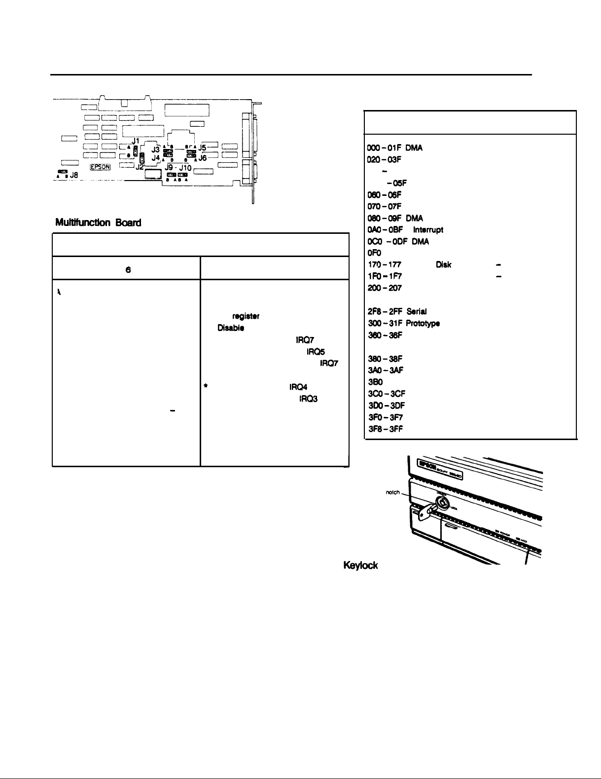
I/O Port Addresses
Address Function
lumper
I 2 3 4 5 6 7 8 9 10
4
A
3 A
4 B
3 B
A A
A B
B A
B B
A A
A B B
B-
A
B
A Video adapter parallel I/F,
A
-
A
B
Function
l Primary register set (Al FDC)
Secondary register sat (AT FDC)
PC register set (FDC)
Disable FDC register set
A
l Primary parallel I/F,
B
Secondary parallel I/F,
Disable parallel I/F
*
Primary serial I/F,
Secondary serial I/F,
Disable serial I/F
l AT -compatible FDD I/F
Equity Ill FDD I/F
l Standard setting
Test mode of VCO
IRQ7
IRQ4
IRQE
IRG3
IRQ7
WO-OlF DMA
020
-03F
022 - 023
040
-05F
060-OBF Keyboard Controller
070-07F
080-OQF
OAO -0BF
CICX -0DF DMA
OF0
-OFF Numeric Coprocessor
17g- 177
1FO - lF7
200-207
278 -27F Parallel Port 2
2F8-2FF
300-31F Robtype
3BO-3BF Reserved
378 -37F Parallel Port 1
3BO-38F SDLC, Bisynchronous Communication 2
3AD-3AF
380 -3BF MDA and Printer Port
3CO-3CF
3DO-3DF
3FO-3F7
3F8-3FF
Controller 1
Interrupt Controller 1
Configuration Registers
Timer/Counter
Real-Time Clock, NMI Mask
DMA
Page Register, MFG Port
interrupt Controller 2
Controller 2
Hard
Disk
Controller
Hard Disk Controller - Primary
Game Port
Bsrlal
Port 2
Card
Bisynchronous Communication 1
Resewed
CGA
floppy Disk Controller
Serial Port 1
-
Secondary
l
Factory
Settings
Equity Series Computers
4/3/89
The keylock on the front panel allows you to disable the
keyboard and RESET button and lock the top cover of the
main unit for security. The keyboard may be locked while the
system is in operation. This disables the keyboard so no
one can interfere with the current operation.
To lock the system, insert the key with the notch pointing
left and turn it clockwise. You must press the key in slightly
when you turn it. To unlock the system, insert the key with
the notch pointing up and turn the key counterclockwise.
You can remove the key in either position.
EQ386/20 - 3
Page 4

EQUITY 386/20
DMA Channels
C%annel
0
1
2
3
4
5
6
7
Spare
Spare
floppy disk transfers
Spare (hard disk drive)
Cascade
Spare
Spare
Hardware Interrupts
CTLR1 CTLR2
IRQO
IRQl
IRQ2
IRQ3
IRQ4
IRQ5
IRQ6
IRQ7
IRQ8
IRQ9
IRQlO
IFtQ11
IRQ12
IRQ13
IRQ14
IRQ15
Timer Output 0
Keyboard
lntbnupt
Serial port 2
Serial port 1
Parallel port 2
Floppy disk interrupt
Parallel port
RTC interrupt
Redirected to
Reserved
Reserved
Reserved
Coprocessor
Hard disk controller
Reserved
Function
of data from
FUNCTION
from Controller 2
1
INTOAH
channel 0 -3
EQ386/20 - 4
4/3/89
Equity Series Computers
Page 5

EQUITY 386/20
Installation/Support Tips
The Equity 386/20 has a power supply that is switchable
between 145 V, for USA and Canadian use, and 230 V, for
USE in Other countries. The voltage switch is located at the
rear of the CPU between the AC inlet and the AC outlet (see
figure below).
WARNING! The voltage is not changed between the AC
inlet and the AC outlet
order to function in Europe, only peripherals certified for use
at 230 V should be plugged into the outlet.
lf
the CPU is switched for
230
V in
---
---
---
---
lf
you are having difficulty in formatting the hard
disk drive, try starting over with the Unconditional
Format option in diagnostics.
When installing an optional expanded memory board
or increasing memory on the internal memory board*
for use as expanded memory, do not list the
memory under the memory expansion option in
SETUP. That option is for EXTENDED memory
ONLY.
lf you are installing an EGA or VGA card, select
SPECIAL OPTIONS as display type in SETUP. This
holds true even when you are using a color or
monochrome monitor with these cards.
When installing a hard disk drive, be sure to consult
the drive type tables (on page EQ386/20 -7) for the
drive type which fits the drive you are installing.
Adding Memory Modules
---
---
The total amount of memory must be one of the
following:1MB. 2 MB.
MB.
Memory banks must be filled with one size SIMM.
You cannot mix SIMM types in one bank.
4 MB,8MB,
10MBor
16
Installing floppy Disk Drives
---
---
When installing a floppy disk drive as drive B,
remember to set the drive select jumper to the
second position and attach the pass-through
connector on the floppy drive controller cable to the
drive, not the end connector.
If the drive does not function normally, make sure
that the drive type has been correctly selected in
SETUP. Also check that any special drivers that
may be necessary have been installed correctly.
Installing Hard Disk Drives
---
It is recommended that a 16-bit AT -type hard
disk controller be used in the Equity 386/20. lf you
must for some reason use an 8-bit, XT -type
controller, select drive type NONE in SETUP.
---
lf you are using more than one memory bank, they
must be filled in pairs. This means you can use 1,
2, or 4 banks. Each pair must be filled with the
same type of SIMMs. You must also fill them in
order. That means that the possible combinations
are Bank 0, Bank 0 and Bank 1, or all four banks.
Using Shadow RAM
---
It is only necessary to enable shadow RAM for the
video ROM if you are using an EGA or VGA card.
CGA, MDA and MGA cards are supported by the
system ROM BIOS. Therefore, they are included in
the shadow RAM setting for the BIOS ROM.
Equity Series Computers
4/3/89
EQ386/20 - 5
Page 6

EQUITY 386/20
Software Problems
---
---
When installing a copy- protected software package
on the Equity 386/20, first try the installation at 20
MHz. If this does not work properly, try switching
to 8 MHz for the installation. lf you are still unable
to load the program at 20 MHz, try loading at 8
MHz and then switching to 20 MHz.
When using a software package that uses a keydisk
as its copy-protection method, try loading it at 20
MHz. lf this does not work, enable the &to Speed
option in SETUP.
EQ386/20 - 6
4/3/89
Equity Series Computer
Page 7

Hard Disk Drive Types
EC!!
I?
16 ST.505
17
18
19
20
21
22
23
24
25
26
27
28
29
30
3'ST 5%732
32
33
34
35
36
37
38
39
a0
1'
42
43
dd
45
46 615
d!
da
a9
STM6
ST5C6
ST.506
ST.503
ST.506 733
I
ST%
ST58
ST506
ST506I306
ST326
ST506
ST5c6
ST506
ST506
ST506
I I
I
ESDI
ESDI 'C22
ST556
I I
612
977
977
1024
733
733
306
612
612
6%
9'6
306
6'1
1023
'C22
'024
326
'024
a20
830
I
4
6
8
6
*
8
5
15
3
5
7
a
1
4
5
7
7
S
7
5
4
4
4
1
7
s
4
4
7
5
a
'2
a
128
17
m
I7
xa
I?
512
I?
512
I?
17
256
17
17
17
17
17
l7
126
'7
0
ml
512
303
3ol
3w
0
305
3w
4.35
0
306
3cQ
512
5'2
'2a
'7
34
36
36
36
34
34
34
34
-
615
306
940
624
940
466
615
204
511
M?
733
334
ass
355
655
497
319
M3
733
426
-
663
977
977
1023
732
732
733
336
663
340
670
732
977
340
663
:32
1023
820
530
1024
528
reserved
203
405
cDC94m51
568
595
304
Toshba MK IDFA
426 ToshaaMK 134FA
304
102
204
102
201
406
405
102
204
426
425
1O"e
W"e
wne
WY
"One
W"e
"One
W"e
wne
,a0 5SeagateST251.
'58 3
Toshiba
'65 SeagaleST4O9f
362
Tortma MK'54F
EQUITY 386/20
-
MK56FB
Equity Series Computers
4/3/89
EQ386/20 - 7
Page 8

EQUITY 366/20
Information Reference List
Engineering Change Notices
None.
Technical Information Bulletins
386/20-001
6/12/89
CHET/CHET-RM Board Connector
Product Support Bulletins
SOO47A
S-0067
S-ooQl
6112189
6/Q/m
4/1Q/aQ
5/16/89
6/12/89
6/12/89
6/13/89
?/l2/89
a/j l/as
a/t l/a9
Using Expanded Memory with the Equity and Apex
Equity Series Computers - ROM History
Apex/Apex Plus/Equity Series Keyboards
Equity
Using the
Common Questions 88 Answers on the Equity
Tape Backup Systems Test Results
Equity/Apex with Sysgen OmniBridge and BridgeFiler Drives
Using High Capacity ESDI and SCSI
Novell Netware Compatibility Test Results for the Equity
366/20
Coprooessor Installation
EEMM366.EXE
Device Driver
366/20
HDDs
with the Equity Series
366/20
Related Documentation
Y162Qgluxo2
Y162991ooMo
M-TM-EQ366
M-PM-E0366
M-PL-EQ366
Y16499100100
4/l/89
3/23/6g
EQ386/20-8
Equity
Equity
Equity
Equity
Equity
Equity
366/20
MSDOS 3.3 Manual
366120
GW-BASIC Manual
366/2O
Technical Manual
366/20
Technical Reference Manual
386/20
Parts List
366120
User’s Guide
9/22/89
Equity Series Computers
 Loading...