

Page 1

®
EPSON
EQUITY® 32Osx PlUS
User’s Guide
Page 2

IMPORTANT NOTICE
DISCLAIMER OF WARRANTY
Epson America makes no representations or warranties, either express or implied,
by or with respect to anything in this manual, and shall not be liable for any
implied warranties of merchantability and fitness for a particular purpose or
for
any indirect, special, or consequential damages. Some states do not allow the
exclusion of incidental or consequential damages, so this exclusion may not apply
to you.
COPYRIGHT NOTICE
All rights reserved. No part of this publication may be reproduced, stored in a
retrieval system, or transmitted, in any form or by any means, electronic,
mechanical, photocopying, recording, or otherwise, without the prior written
permission of Epson America, Inc. No patent liability is assumed with respect to
the use of information contained herein. Nor is any liability assumed for damages
resulting from the use of the information contained herein. Further, this
publication and features described herein are subject to change without notice.
TRADEMARKS
Epson is a registered trademark of Seiko Epson Corporation.
Equity is a registered trademark of Epson America, Inc.
General notice: Other product names used herein are for identification purposes
only and may be trademarks of their respective companies.
Copyright © 1991 by Epson America, Inc.
Torrance, California
ii
Y740991001
Page 3

FCC COMPLIANCE STATEMENT FOR AMERICAN USERS
This equipment has been tested and found to comply with the limits for a class B
digital device, pursuant to Part 15 of the FCC Rules. These limits are designed to
provide reasonable protection against hamrful interference in a residential
installation. This equipment generates, uses and can radiate radio frequency energy
and, if not installed and used in accordance with the instructions, may cause
harmful interference to radio or television reception. However, there is no
guarantee that interference will not occur in a particular installation. If this
equipment does cause interference to radio and television reception, which can be
determined by turning the equipment off and on, the user is encouraged to try to
correct the interference by one or more of the following measures:
l
Reorient or relocate the receiving antenna
l
Increase the separation between the equipment and receiver
l
Connect the equipment into an outlet on a circuit different from that to which
the receiver is connected
l
Consult the dealer or an experienced radio/TV technician for help.
WARNING
The connection of a non-shielded equipment interface cable to this equipment will
invalidate the FCC Certification of this device and may cause interference levels
which exceed the limits established by the FCC for this equipment. It is the
responsibility of the user to obtain and use a shielded equipment interface cable
with this device. If this equipment has more than one interface connector, do not
leave cables connected to unused interfaces.
Changes or modifications not expressly approved by the manufacturer could void
the user’s authority to operate the equipment.
FOR CANADIAN USERS
This digital apparatus does not exceed the Class B limits for radio noise emissions
from digital apparatus as set out in the radio interference regulations of the
Canadian Department of Communications.
Le present appareil numérique n’emet pas de bruits radioélectriques dépassant les
limites applicables aux appareils numériques de Classe B prescrites dans le
réglement sur le brouillage radioéctrique édicté par le Ministére des
Communications du Canada.
Page 4

Important Safety Instructions
1.
Read all of these instructions and save them for later reference.
Follow all warnings and instructions marked on the product.
2.
Unplug this product from the wall outlet before cleaning. Use
3.
a damp cloth for cleaning, not liquid cleaners or aerosol
cleaners.
4.
Do not use this product near water.
Do not place this product on an unstable cart, stand, or table.
5.
Slots and openings in the cabinet and the back or bottom are
6.
provided for ventilation; these openings must not be blocked
or covered. This product should never be placed near or over a
radiator or heat register.
This product should be operated from the type of power
7.
source indicated on the marking label. If you are not sure of
the type of power available, consult your dealer or local power
company.
8.
Connect all equipment to properly grounded (earthed) power
outlets. If you are unable to insert the plug into the outlet,
contact your electrician to replace your obsolete outlet. Avoid
using outlets on the same circuit as photocopiers or air control
systems that regularly switch on and off.
Do not locate this product where the cord will be walked on.
9.
10. If an extension cord is used with this product, make sure that
the total of the ampere ratings on the products plugged into
the extension cord do not exceed the extension cord ampere
rating. Also, make sure that the total of all products plugged
into the wall outlet does not exceed 15 amperes.
11. Never push objects of any kind into this product through the
cabinet slots. Never spill liquid of any kind on the product.
12. Except as specifically explained in the User’s Guide, do not
attempt to service this product yourself. Refer all servicing to
qualified service personnel.
Page 5

13. Unplug this product from the wall outlet and refer servicing to
qualified service personnel under the following conditions:
A.
When the power cord or plug is damaged.
B.
If liquid has entered the product.
C.
If the product does not operate normally when the
operating instructions are followed. Adjust only those
controls that are covered by the operating instructions,
since improper adjustment of other controls may result in
damage and will often require extensive work by a
qualified technician to restore the product to normal
operation.
D.
If the product has been dropped or the cabinet has been
damaged.
E.
If the product exhibits a distinct change in performance.
iV
Page 6

Importantes Mesures de Séurité
Lire attentivement les instructions qui suivent. Les conserver
1.
en lieu stir.
Observer les avertissements et suivre rigoureusement les
2.
instructions marquees sur l’ordinateur.
Debrancher l’appareil avant de le nettoyer. Se servir d’un
3.
chiffon humide, sans detergents ni aerosols.
Ne pas se servir de l’ordinateur pres de l’eau.
4.
Ne pas placer l’appareil sur un meuble instable.
5.
Les ouvertures et fentes à l’arrière et au dessous du coffre en
6.
assurent la ventilation. 11 est important de ne pas couvrir ni
bloquer ces prises d’air. De meme, il ne faut jamais placer
l’ordinateur près d’un appareil de chauffage.
N’utiliser comme type de courant que celui qui est indique sur
7.
l’etiquette. En cas de doute, consultez votre distributeur ou la
compagnie électrique de votre secteur.
Toutes les connexions électriques doivent être des connexions
8.
de sècurite, avec contact de terre. Si la fiche de sécurité n’entre
pas dans le socle de prise de courant, demander a un
electricien de remplacer l’ancien socle par un socle neuf. Eviter
de brancher l’ordinateur sur le même circuit que des machines
qui se mettent en marche et s’arriêtent tour a tour, telles que
photocopieurs ou climatiseurs.
Ne pas laisser de fils ou cordons électriques dans un lieu de
9.
passage; éviter de leur marcher dessus.
10. S’il est nécessaire d’employer un cordon prolongateur pour
brancher l’appareil, s’assurer que la consommation d’energie
totale des machines branchees sur le cordon prolongateur ne
depasse pas la capacite en amperes dudit cordon. L’ampérage
total de toutes les pièces branchees sur le socle ne doit pas
depasser 15 amperes.
11. Ne jamais rien introduire dans les prises d’air. Ne pas renverser
de liquide sur l’appareil.
V
Page 7

12. Sauf dans les cas specifiquement indiques dans le Guide de
l’utilisateur, ne pas essayer de réparer l’ordinateur soi-même;
s’adresser à un spécialiste qualifié.
13. Debrancher l’appareil et s’adresser au personnel de service
qualifie dans les cas suivants:
A.
Lorsque le cordon, les broches, la prise ou le socle sont
endommages.
B.
Lorsqu’un liquide a pénétré a l’interieur de l’appareil.
C.
Lorsque l’ordinateur ne répond pas normalement aux
commandes passées en suivant les instructions. Ajuster
uniquement les controles décrits dans les instructions; il
est possible de gravement endommager l’appareil en
touchant les autres, ce qui pourrait nécessiter
l’intervention d’un technicien qualifié pour le remettre en
état de marche.
D.
Lorsque l’appareil est tombe ou le coffre a été endommagé.
E.
Lorsque la performance de l’ordinateur est nettement
inferieure a l’ordinaire.
vi
Page 8

Contents
Introduction
Optional Equipment
Operating Systems and Other Software
VGA Utilities
How to Use This Manual ............................ 3
Where to Get Help.
Chapter 1
1 Choosing a Location
2 Removing the Protector Card
3 Connecting a Monitor
Using the VGA Interface.
Using a Display Adapter Card.
4 Connecting a Printer or Other Device
Using the Parallel Interface.
Using the Serial Interface
5 Connecting the Keyboard
6 Connecting the Mouse
7 Connecting the Power Cord
8 Turning On the Computer
Turning Off the Computer
.....................................
...............................
................
................................
Setting Up Your System
.............................
......................
...........................
.......................
...................
...............
.....................
.......................
.........................
...........................
.......................
........................
......................
1
2
2
4
l-l
l-3
l-4
1-4
l-7
1-8
l-8
l-l1
1-12
1-13
1-15
1-16
1-18
Chapter 2
Starting the SETUP Program
Selecting Options
Setting the Date and Time.
Setting the Diskette Drive(s)
Setting the Hard Disk Drive(s).
Hard Disk Drive Types
Running the SETUP Program
.........................
.............................
..........................
.........................
.........................
.......................
2-2
2-3
2-3
2-4
2-5
2-5
vii
Page 9

Setting the Primary Display Type
Setting the Keyboard Test Function
Setting the Shadow RAM.
Setting the CPU Clock Speed
EMSSize
Setting the Password
Setting the BuiIt-in Interfaces
Saving Your Settings
.........................................
Changing or Deleting a Password.
Setting the Parallel Interface.
Setting the Serial Interface
Setting the Disk Drive Controllers
...........................
...............................
...............................
.....................
........................
........................
......................
...................
................
....................
................
2-8
2-9
2-10
2-11
2-12
2-13
2-14
2-15
2-15
2-16
2-l 6
2-16
Chapter 3
Installing MS-DOS or Another Operating System
Special Keys on the Keyboard
Stopping a Command or Program
Resetting the Computer
Using a Password.
Using Disks and Disk Drives
How Disks Store Data
Types of Diskette Drives
Caring for Diskettes and Diskette Drives
Write-protecting Diskettes
Using a Single Diskette Drive System
Inserting and Removing Diskettes
Formatting Diskettes
Making Backup Copies
Using a Hard Disk Drive
Using Your
.................................
Computer
........................
....................
............................
.........................
..........................
........................
...........
......................
..............
................
...........................
.........................
........................
........
3-1
3-2
3-3
3-4
3-5
3-6
3-6
3-8
3-10
3-12
3-14
3-15
3-l 7
3-l 7
3-18
viii
Page 10

Chapter 4
Enhancing System Operations
Using AUTOEXEC.BAT and Other Batch Files
Changing the Processor Speed
Entering Keyboard Commands.
Using the ESPEED Program.
Using Expanded Memory Beyond 640KB.
Modifying the CONFIG.SYS File
Using the VGA Utilities.
Chapter 5
Removing the Cover
Removing the Subassembly.
Replacing the Subassembly
Replacing the Cover
Chapter 6
Changing the Jumper Settings
Setting the Jumpers.
Replacing the Battery
Installing an Option Card
Removing an Option Card
Adding Memory Modules
Installing Memory Modules
Removing Memory Modules.
Installing a Math Coprocessor
Removing a Math Coprocessor
Post-installation Setup for Memory Cards
Post-installation Setup.
Accessing Internal Components
...............................
...............................
Installing and Removing Options
..............................
.............................
.......................
..................
.....................
..................
............................
.........................
..........................
.......................
...........................
...........................
..........................
...........................
.....................
....................
.......................
.......................
...........
..............
..............
4-l
4-2
4-4
4-5
4-7
4-8
4-11
5-2
5-5
5-9
5-17
6-2
6-3
6-5
6-9
6-13
6-14
6-15
6-18
6-21
6-24
6-25
6-25
ix
Page 11

Chapter 7
Installing and Removing Disk Drives
Using the Correct Drive Bay
How to Use This Chapter
Setting the Hard Disk Drive Jumpers
Changing the Jumper Settings
Installing a Hard Disk in the Vertical Position
.........................
...........................
..................
...................
...........
Removing the Mounting Frames From the Drive.
Removing and Attaching the Mounting Plate
Installing the Drive
............................
Removing a Hard Disk From the Vertical Position
Installing or Removing a Drive in the
Horizontal Position.
.........................
Installing a Drive in the Horizontal Position
Removing a Drive From the Horizontal Position.
Appendix A
CPU and Memory
Controllers.
Interfaces
Power Supply.
Mass Storage
Keyboard
Environmental Requirements
Physical Characteristics.
System Memory Map.
Specifications
.................................
......................................
........................................
....................................
.....................................
........................................
........................
............................
..............................
....
.......
........
........
....
7-2
7-3
7-4
7-5
7-7
7-8
7-10
7-l 1
7-17
7-19
7-19
7-27
A-l
A-2
A-2
A-3
A-3
A-4
A-4
A-4
A-5
x
Page 12

Appendix B
Performing System Diagnostics
Starting the Diagnostics Program . . . . . . . . . . . . . . . . . . . . .
The Main Menu Screen . . . . . . . . . . . . . . . . . . . . . . . . . . . . .
Setting the Run Time Parameters . . . . . . . . . . . . . . . . . . . . .
Error Logging. . . . . . . . . . . . . . . . . . . . . . . . . . . . . . . . .
Selecting Diagnostic Tests . . . . . . . . . . . . . . . . . . . . . . . . . . .
Selecting Multiple Tests . . . . . . . . . . . . . . . . . . . . . . . .
Running the Tests . . . . . . . . . . . . . . . . . . . . . . . . . . . . . . . . .
Memory Diagnostics . . . . . . . . . . . . . . . . . . . . . . . . . . . . . . .
Hard Disk Diagnostics . . . . . . . . . . . . . . . . . . . . . . . . . . . . . .
Hard Disk Parameters . . . . . . . . . . . . . . . . . . . . . . . . . .
Hard Disk Format . . . . . . . . . . . . . . . . . . . . . . . . . . . . .
Media Analysis . . . . . . . . . . . . . . . . . . . . . . . . . . . . . . .
Performance Test. . . . . . . . . . . . . . . . . . . . . . . . . . . . . .
SeekTest....................................
Read/Verify Test . . . . . . . . . . . . . . . . . . . . . . . . . . . . . .
Check Test Cylinder . . . . . . . . . . . . . . . . . . . . . . . . . . .
Force Bad Tracks . . . . . . . . . . . . . . . . . . . . . . . . . . . . . .
Hard Disk Error Messages . . . . . . . . . . . . . . . . . . . . . . .
Floppy Disk Diagnostics . . . . . . . . . . . . . . . . . . . . . . . . . . . .
Performing the Tests . . . . . . . . . . . . . . . . . . . . . . . . . . .
Floppy Disk Error Messages. . . . . . . . . . . . . . . . . . . . . .
Miscellaneous Diagnostics. . . . . . . . . . . . . . . . . . . . . . . . . . .
Printer Adapter Test . . . . . . . . . . . . . . . . . . . . . . . . . . .
Communication Adapter Test. . . . . . . . . . . . . . . . . . . .
Exiting System Diagnostics . . . . . . . . . . . . . . . . . . . . . . . . . .
B-2
B-2
B-4
B-6
B-8
B-8
B-10
B-12
B-12
B-13
B-16
B-l 7
B-18
B-18
B-18
B- 19
B-19
B-19
B-20
B-21
B-22
B-23
B-23
B-24
B-25
xi
Page 13

Appendix
Troubleshooting
C
Identifying Your System
Error Messages
....................................
The Computer Won’t Start
............................
..........................
The Computer Does Not Respond
Password Problems
................................
Accessing Your Current Password.
Keyboard Problems
Monitor Problems
Diskette Problems
Diskette Drive Problems
Hard Disk Problems.
Installing the Drive.
Preparing the Drive
................................
.................................
.................................
............................
...............................
...........................
............................
Accessing Data on the Drive.
Software Problems
Printer Problems
Option Card Problems.
Mouse Problems
Memory Module Problems
Battery Problems
Math Coprocessor Problems
.................................
..................................
.............................
..................................
..........................
..................................
.........................
Glossary
....................
................
....................
C-l
C-2
C-3
C-4
C-5
C-6
C-7
C-8
C-9
C-11
C-12
C-13
C-14
C-14
C-15
C-16
C-17
C-18
C-19
C-19
C-20
Index
Xii
Page 14

Introduction
The Epson® Equity® 320sx PLUS is a high-performance
personal computer which offers exceptional speed and
convenience in a compact design.
Your 20 MHz, 80386SX system includes 2MB of internal
memory, a built-in VGA (video graphics array) display
adapter, built-in parallel and serial interfaces, and an IBM
PS/2™ compatible mouse port. These interfaces allow you to
connect most of your peripheral devices directly to the
computer, so you do not have to install option cards.
The Equity 320sx PLUS also provides four option slots (three
16-bit and one 8-bit) in which you can install additional
devices, such as a modem or a network card.
Your computer can support up to three internal drives: either
two diskette drives and one hard disk drive, or one diskette
drive and two hard disk drives.
Additionally, your system offers shadow RAM to speed up
processing by moving the ROM BIOS and the video ROM
into the RAM area of memory. This allows the computer to
access and display information faster.
®
Optional Equipment
You can easily upgrade your computer by installing
additional memory and adding just about any optional
device that is compatible with the IBM Personal Computer,
PC XT,” or PC AT.”
By adding memory modules to the main system board, you
can expand the computer’s memory up to 24MB. The first
16MB can be used as either extended or expanded memory;
any memory above 16MB can be used only as expanded.
Introduction 1
Page 15

You may want to install an 80387SX, 20 MHz math
coprocessor in your computer to speed up mathematical
calculations in certain application programs.
Check with your authorized Epson dealer for information on
optional equipment.
Operating Systems and Other Software
You probably have a version of MS-DOS® to use with your
computer. However, you can run another operating system,
such as, OS/2, UNIX
operating system, refer to the documentation that came with
it to install and run it on your computer.
You can use virtually any application program designed for
the IBM PC, PC XT, PC AT, or compatible computers on your
Equity 320sx PLUS. You may also use powerful 32-bit
software designed for 80386 computers with your system.
®
or XENIX® If you use another
VGA Utilities
Epson has included special VGA device drivers and utilities
that you can use with your built-in VGA adapter. With these
utilities, you can take advantage of extended VGA features
such as 16-color graphics mode resolutions up to 800 x 600
and 132-column text mode. The VGA device drivers and
utilities are described in the VGA Utilities booklet that came
with your system.
2 Introduction
Page 16

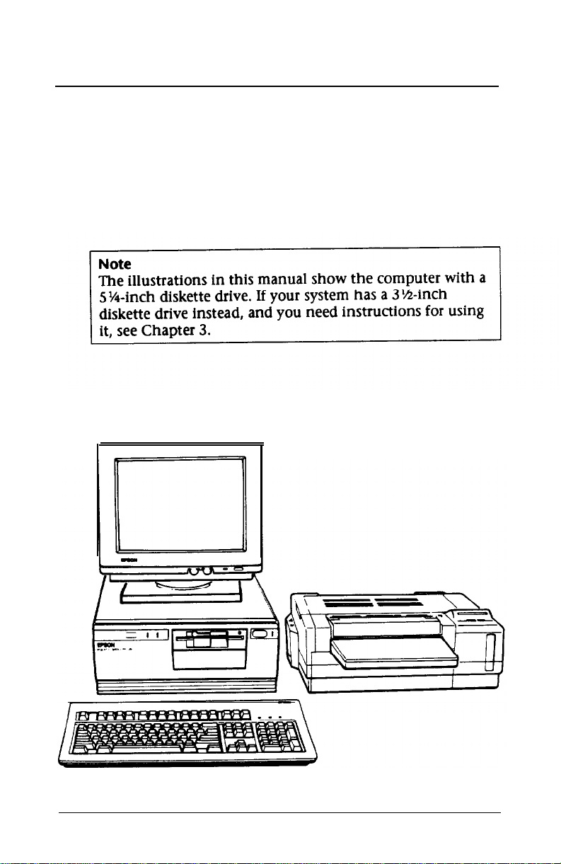
How to Use This Manual
This manual explains how to set up and operate your
computer, install options, and run diagnostic checks.
Although the illustrations show a computer with a 21/4-inch
diskette drive, instructions for using a 31/2-inch drive are
included.
You do not need to read everything in this book; see the
following chapter summaries.
Chapter 1 provides simple step-by-step instructions for
setting up your system. On the back cover foldout are
illustrations identifying the different parts of your computer;
refer to these as you set up your system.
Chapter 2 describes how to run the SETUP program to define
your computer’s configuration. Do this before you use your
computer. You may need to do it again later, if you change
the configuration.
Chapter 3 provides instructions for important operating
procedures, such as using and caring for disks and disk drives.
Chapter 4 describes specialized features you can use to
enhance your system’s performance.
Chapter 5 describes how to remove and replace the
computer’s cover and subassembly to access the internal
components.
Chapter 6 describes some of the options you can use in your
computer and contains instructions for setting jumpers,
replacing the battery, and installing options.
Introduction 3
Page 17

Chapter 7 describes how to install and remove disk drives.
Appendix A gives the technical specifications for the
computer.
Appendix B outlines the system diagnostic tests you can run
to diagnose hardware problems.
Appendix C contains troubleshooting tips.
At the end of the manual, you’ll find a glossary and an index.
Where to Get Help
If you purchased your Epson product in the United States,
Epson America provides local customer support and service
through a nationwide network of authorized Epson dealers
and Service Centers.
Epson also provides the following support services through
the Epson Consumer Resource Center at (800) 922-89 11:
Assistance in locating your nearest Authorized Epson
Reseller or Service Center
Technical assistance with the installation, configuration,
and operation of Epson products
Epson technical information library fax service
Product literature with technical specifications on our
current and new products
Sales of ribbons, supplies, parts, documentation, and
accessories for your Epson product
Customer Relations.
4 introduction
Page 18
Chapter 1
Setting Up Your System
Setting up your Equity 320sx PLUS personal computer is easy.
Just follow the eight steps in this chapter. As you set up your
system, you may want to leave this manual’s back cover
foldout open so you can refer to the illustrations identifying
the different parts.
Choosing a Location
1
Setting Up Your System
1-1
Page 19

Before you set up your computer, it’s important to choose a
safe, convenient location that provides the following:
0
A sturdy desk or table strong enough to support the
weight of your system and all of its components.
0
A flat, hard surface. Soft surfaces like beds and carpeted
floors attract static electricity, which can erase data on
your disks, damage the computer’s circuitry, and prevent
proper ventilation.
cl
Good air circulation. Leave several inches of space around
the computer so air can move freely.
cl
Moderate environmental conditions. Select a cool, dry
area and protect your computer from extremes in
temperature, humidity, dust, and smoke. Avoid direct
sunlight or any other source of heat.
cl
Appropriate power sources. To prevent static charges,
connect all your equipment to three-hole, 120-volt
grounded outlets. You need one outlet for the computer,
one for the monitor, and additional outlets for a printer
and any other peripheral devices.
0
No electromagnetic interference. Do not place your
system too dose to any electrical device, such as a
telephone, which generates an electromagnetic field.
1-2
Setting Up Your System
Page 20
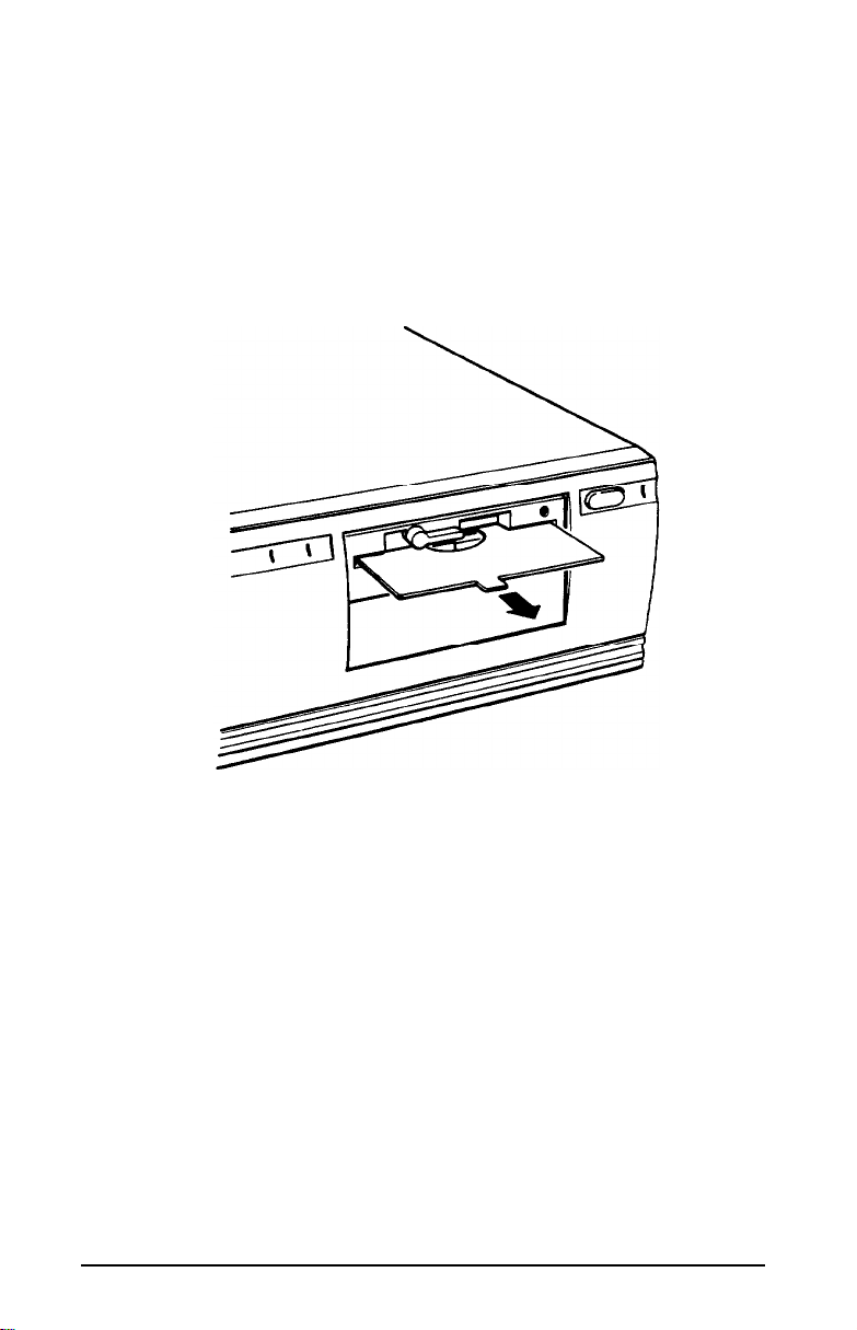
2 Removing the Protector Cord
If you have a SW-inch
in the diskette slot. This card is inserted at the factory to
protect the read/write heads in the drive. To remove it, flip
the latch up to pop the card out part way, as shown below;
then pull it out.
(If you have a second 51/4-inch diskette drive, be sure to
remove the protector card from it.)
diskette
drive, there is a protector card
Save the protector card. If you transport your computer, you
may want to insert the card into your diskette drive prior to
shipping. This will protect the read/write heads during the
shipping process.
Setting Up Your System
1-3
Page 21

3
Connecting a Monitor
The way you connect your monitor to the computer depends
on the type of monitor you have. If you have a VGA monitor
(or a multi-frequency monitor with an analog connector),
you can connect it to the computer’s built-in VGA port. See
“Using the VGA Interface” below. If you have any other type
of monitor, see “Using a Display Adapter Card” on page 1-7.
Using the VGA interface
Follow these steps to connect your VGA monitor to the VGA
port on the computer:
1.
Make sure your monitor and computer are turned off.
2.
Place your monitor on top of or near the computer. For
easy access, turn the monitor and computer around so
the backs of both components are facing you.
3.
If necessary, connect the monitor cable to the monitor.
(Your monitor may have a permanently attached cable.)
1-4
Setting up Your System
Page 22
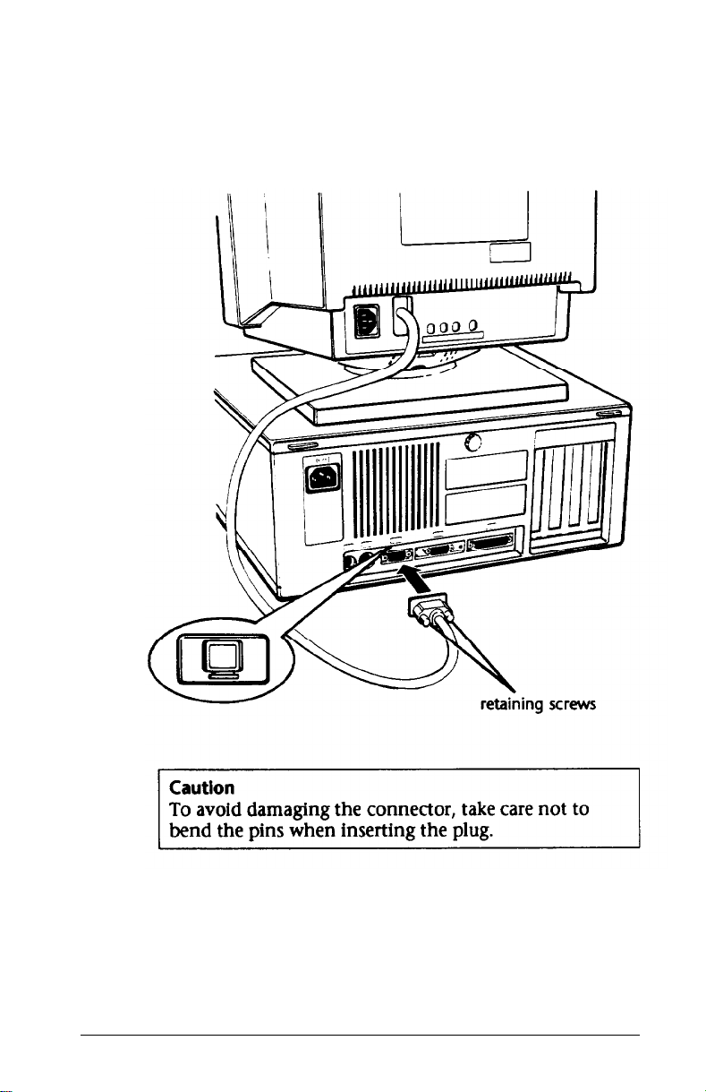
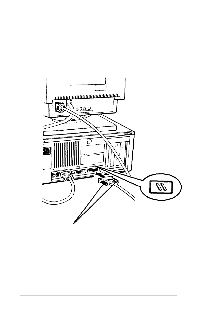
4.
Examine the connector end of the monitor cable, and
position the plug to match the orientation of the
monitor port (marked with a monitor icon). Then insert
the plug into the port, as shown below.
5.
If the connector has retaining screws, be sure to tighten
them.
Setting Up Your System
1-5
Page 23
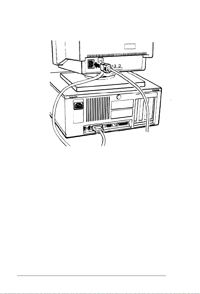
6.
Plug the monitor power cord into the monitor’s power
inlet, as shown below.
7.
Plug the other end of the power cord into an electrical
outlet.
1-6
Setting Up Your System
Page 24
Using a Display Adapter Card
If you are using a non-VGA monitor, you’ll need to install a
display adapter (video) card in one of the computer’s option
slots before you can connect the monitor. your dealer may
have already installed the video card for you.}
If the video card has not yet been installed, you’ll need to
follow the instructions in Chapter 6 to install an option card.
But first, check the following table to make sure your display
adapter card and monitor are properly matched.
Monitor/video card compatibility
Monitor
Monochrome
Color or EGA
Monochrome or
or color VGA
+
EGA cards support only EGA monitors.
Video card
Monochrome display adapter (MDA)
Multi-mode graphics adapter (MCA)
Enhanced graphics adapter (EGA)
Hercules
Color graphics adapter (CGA)
Multi-mode graphics adapter (MGA)
Enhanced graphics adapter (EGA)’
Video graphics array (VGA)
®
graphics card
When you are installing the video card, check to make sure
any switches or jumpers on the card are set properly. For
example, you may need to change a switch setting to select
color or monochrome. See the documentation that came
with your monitor or video card for instructions.
Setting
Up
Your System
1-7
Page 25

Note
If you install a display adapter card, you must set jumper
Jl on the main system board to disable the built-in VGA
interface so that your card can operate as the primary
display adapter. You may also need to set jumper J3 to
indicate whether a color or monochrome monitor is
installed. See Chapter 6 for instructions on changing
jumper settings.
Once you have installed your video card, return to this
section to connect your monitor to the computer. If your
monitor came with its own manual, follow the instructions
there. Otherwise, you can follow the steps in “Using the VGA
Interface” on page 1-4; just insert your monitor connector
into the video card port instead of the built-in VGA port.
4
Connecting a Printer or Other Device
Your computer has both parallel and serial interfaces. To
connect a printer or other peripheral device to one of these
interfaces, follow the instructions below.
Using the Parallel Interface
The parallel interface on your computer is Centronics
compatible and uses a DB-25S connector.
To connect your printer and computer, you need an IBM
compatible printer cable. If you are not sure which cable you
need, check with your Epson dealer.
Once you have the right printer cable, follow these steps:
1.
Make sure the printer and computer are turned off.
2.
Place the printer next to the computer with their backs
facing you.
1-8
Setting Up Your System
®
Page 26
3.
One end of the printer cable has a 25-pin, D-shell
connector. Position the plug to match the orientation of
the parallel interface (marked with a special icon shown
in the illustration below). Then plug the connector into
the port, as shown below. If the plug has retaining
screws, tighten them by hand or with a screwdriver,
depending on the screw type.
retaining screws
Setting Up Your System
1-9
Page 27
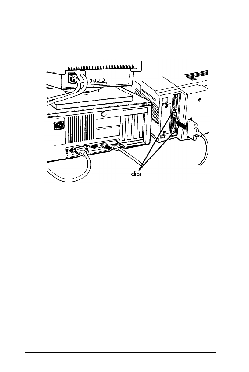
4.
Connect the other end of the cable to the printer as
shown below. To secure the cable, squeeze the clips at
each side of the printer port and push them into place.
5.
Plug the printer’s power cord into a three-hole, 120-volt,
grounded electrical outlet.
1-10
Setting Up Your System
Page 28
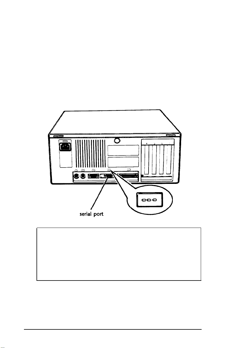
Using the Serial lnterface
If you have a printer, a modem, or other peripheral device
with a serial interface, you can connect it to the serial
(IR-232C) port on the back of the computer.
The serial port uses a DB-9P connector, so be sure you have a
compatible cable. To connect a serial device, follow the same
steps as above for connecting a parallel device but insert the
connector into the serial port, marked with a special icon, as
shown below.
Note
You need to ensure that the serial port is set up so it
functions properly. If you are using the port for a serial
printer, you need to redirect printer output to the serial
port instead of the parallel port. To do this, you can use
the MS-DOS MODE or SETMODE command. See your
MS-DOS manuals for instructions.
Setting Up
Your
System
1-11
Page 29
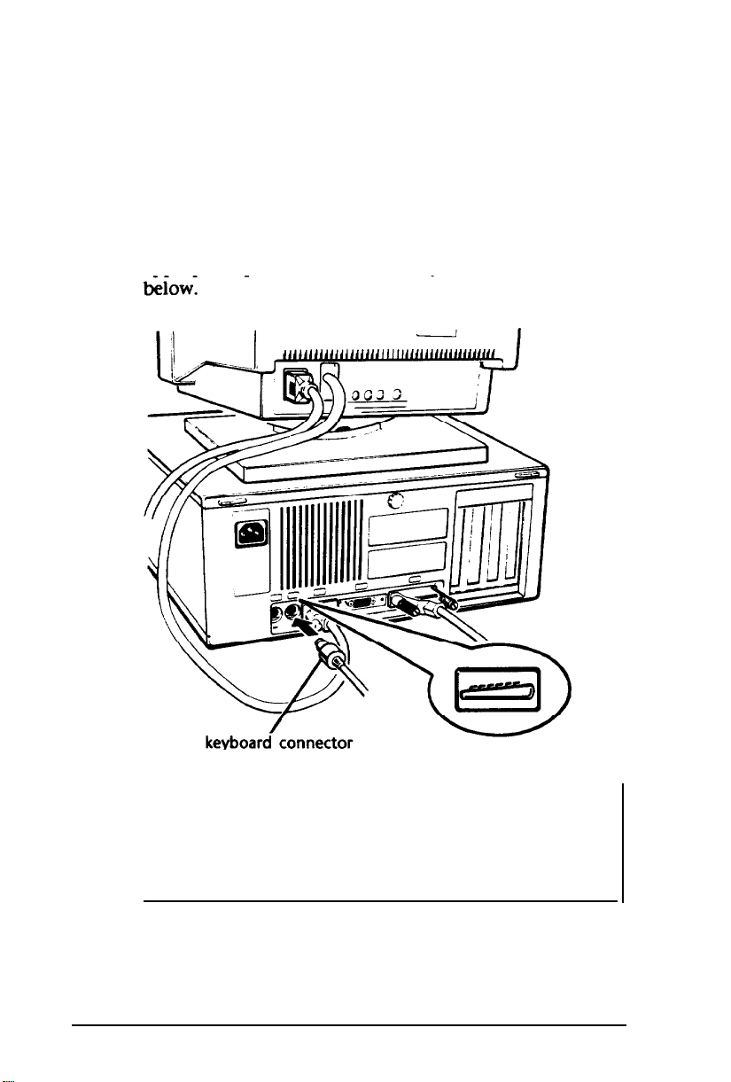
5
Connecting the Keyboard
Follow these steps to connect the keyboard:
1.
Make sure the computer is turned off.
2.
Hold the keyboard cable connector so the indicator on
the housing faces up. Insert the connector into the
appropriate port, marked with a keyboard icon, as shown
1-12
Although the connectors and ports for the keyboard
and mouse are physically identical, they cannot be
used interchangeably. Be sure to plug the keyboard
Setting Up Your System
Page 30
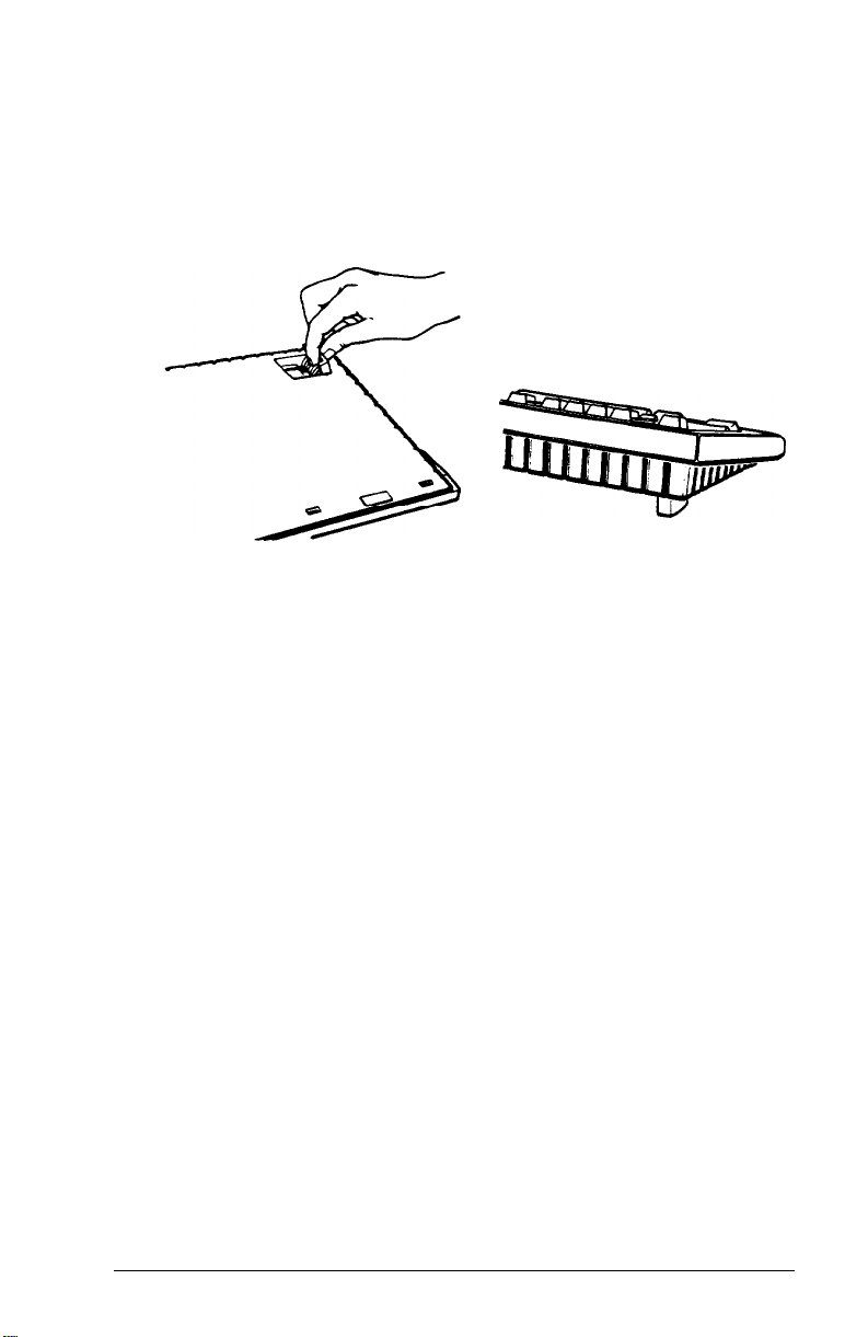
3.
You can raise the keyboard by adjusting the legs on the
bottom. To change the angle of the keyboard, turn it over
and flip each leg upward until it locks into place, as
shown below.
6 Connecting the Mouse
Your computer has an auxiliary port for an IBM PS/2
compatible mouse that uses a miniature DIN (6-pin)
connector.
Before you connect a mouse, make sure your computer is
turned off.
If your mouse has this type of connector, you can connect it
to the built-in port on your computer. If you have a mouse
that requires a different interface port, you can connect it to
the built-in serial port or install an option card to provide the
interface.
To connect a mouse to the built-in mouse port, hold the
mouse connector so it is oriented properly with its port.
Insert the connector, marked with a mouse icon, as shown in
the following illustration.
Setting Up Your System
1-13
Page 31

mouse connector
Once you have connected a mouse, you may need to add
commands to your MS-DOS CONFIG.SYS file to enable your
computer to use a mouse. See your MS-DOS and mouse
manuals for instructions.
If you want to use a mouse or other pointing device
1-14
Setting Up
Your
System
Page 32

7 Connecting the Power Cord
Follow these steps to connect the power cord:
1.
Plug the power cord into the AC power inlet on the back
panel, as shown below.
WARNING
To avoid an electric shock, be sure to plug the cord
into the computer before plugging it into the wall
socket.
2.
Plug the other end of the power cord into a three-hole,
120-volt, grounded electrical outlet.
Setting Up Your
System
l-15
Page 33

Turning On the Computer
8
After you set up your system, you’re ready to turn on the
power. But first, read the following safety rules to avoid
accidentally damaging your computer or injuring yourself:
Do not connect or disconnect any peripheral device or
a
power cables when the computer’s power is on.
Never turn on the computer with a protector card in the
a
diskette drive.
Never turn off or reset your computer while a disk drive
a
light is on. This can destroy data stored on the disk.
Always wait at least five seconds after you turn off the
a
power before you turn it on again. This allows the
computer to clear and reset its memory.
a
Do not leave a beverage near your system or any of its
components. Spilled liquid can damage the circuitry of
your equipment.
a
Always turn off the power, disconnect the computer’s
power cord, and wait 30 seconds before you remove the
cover. Only remove the cover to access internal devices,
add memory, change jumper settings, or replace the
battery.
Follow these steps to turn on your system:
1.
Make sure the power cord is plugged into the AC power
inlet on the back panel of the computer and into a
three-hole, 120-volt, grounded electrical outlet.
2.
Turn your computer around so the front panel faces you
and place your other system components in an
arrangement that suits you. (See step 1, “Choosing a
Location,” for a typical arrangement.)
3.
Turn on the monitor, printer, and any other peripheral
devices connected to the computer.
1-16
Setting Up YourSystem
Page 34

4.
To turn on the computer, press the power button located
on the right side of the front panel, as shown below.
power button
The power indicator next to the button lights up. After a few
seconds, the computer counts the amount of memory in
your computer, and then performs a diagnostic self test. This
is a series of checks the computer completes each time you
turn it on to make sure everything is working correctly.
If necessary, use the controls on your monitor to adjust the
brightness and contrast until characters on the screen are
clear and at a comfortable level of intensity. If your monitor
has horizontal and vertical hold controls, you may need to
use them to stabilize the display.
Note
If you or your dealer have made a major change to your
system, such as adding a disk drive, you may need to wait
a few minutes for your computer to complete power-on
diagnostics the first time you turn it on.
Setting Up Your System
1-17
Page 35

When the system has successfully completed its self test, you
see the following prompt:
Press <Del> to start SETUP
Do not press any key yet. If MS-DOS has already been
installed on your system, you’ll see a prompt to enter the
date. (For information about loading the operating system,
see your MS-DOS manuals.)
If there is no operating system on your computer, you see an
error message. Ignore the message for now. Follow the
instructions below to turn off the computer and then go on
to Chapter 2 for instructions on running the SETUP program.
Note
If your computer’s configuration does not match the
information stored in the computer’s CMOS RAM (defined
through the SETUP program), you see an error message
and a prompt to press the F1 key. Press F1 to continue.
Then run the SETUP program to correct the information.
(See Chapter 2 for instructions.)
Turning Off the Computer
When you are ready to turn off your system, reverse the
sequence of steps you followed to turn it on. Turn off the
computer first, then turn off the monitor and any peripheral
devices.
Now go on to Chapter 2 and follow the instructions to run
the SETUP program.
1-18 Setting
Up Your System
Page 36

Chapter 2
Running the SETUP Program
When you use your computer for the first time, you need to
run the SETUP program to define how your system is set up.
This is a simple procedure which you must do at least once.
You may need to run it again later if you change some part of
your configuration.
The SETUP program is stored in the computer’s read-only
memory (ROM), so you can run the program any time you
turn on or reset your computer. You do not need to insert a
diskette or access the hard disk.
SETUP lets you verify or change the following:
0
Current date and time
tl
Type of diskette drives(s) installed
cl
Type of hard disk drive(s) installed
D
Type of video display adapter you are using
0
Keyboard testing function
Cl
Shadow RAM function
0
CPU clock speed
P
EMS size
0
Password feature
0
Built-in interface settings for the parallel and serial ports,
and the diskette and hard disk drive controllers.
Running the SETUP Program
2-1
Page 37

The configuration you define through SETUP is stored in a
special area of memory called CMOS RAM. This memory is
backed up by a battery, so it will not be erased when you
turn off or reset the computer. Whenever you reboot the
computer, it checks the settings, and if it discovers a
difference between the information in the CMOS RAM and
your system’s configuration, it prompts you to run SETUP.
You see a message such as the following:
CMOS memory size mismatch
RUN SETUP
Press <Fl> to RESUME
Press
F1
to run SETUP and correct the setting.
UTILITY
Starting the SETUP Program
To start the SETUP program, make sure there is no diskette
in the diskette drive; then turn on your computer. (If the
computer is already on, press the
panel to reset it.)
After the computer completes its self test, you see the
following prompt:
RESET
button on the front
Press <Del> to start SETUP
As soon as you see this message, press the
not press
Del
within five seconds, the computer starts loading
Del
key. If you do
the operating system and you will not be able to run SETUP.
If this happens, reset the computer and try again.
You see the following options:
Start operating system
Run SETUP
The first option is highlighted. Press 4 to highlight
SETUP,
and then press
Enter. The
SETUP menu appears on
Run
the screen.
2-2
Running the SETUP Program
Page 38

The menu automatically displays the base memory size, the
extended memory size, and whether a math coprocessor
(numeric processor) is installed. Additionally, the SETUP
menu lists the parameters you can change.
Selecting Options
A solid cursor bar highlights the parameter currently selected.
You can scroll through the parameters using the four arrow
keys (
‘ , ’ , “
change, press
Page Up
,
”
or
). When you reach a parameter you want to
Page Down
to display and select
the available options.
An information window appears at the bottom of the menu;
it describes the options available or any other keys to press to
change the highlighted configuration parameter.
The rest of this chapter describes how to choose the correct
SETUP parameters for your system.
Setting the Date and Time
The real-time clock in your computer continously tracks the
date and time-even when the computer is turned off. Once
you set the date and time using SETUP, you should not need
to change either parameter, except to adjust the time for
daylight savings, if necessary. (The computer automatically
changes the date for leap years.)
The current month is highlighted and a calendar on the right
side of the screen shows all the days for the month. The
current day is flashing. Press
Page Up
or
Page Down
to select
the correct month, day, and year.
To change the time, move the cursor to the next line and
press
Page Up
or
Page Down
to enter the correct hour and
minutes according to a 24-hour clock. For example, 5 p.m.
would be hour 17. You cannot set the number of seconds.
Running the SETUP Program
2-3
Page 39

Setting the Diskette Drive(s)
Your system probably came with one diskette drive installed
and you may have another drive of a different size or
capacity. The SETUP menu offers five possible selections for
your diskette drives (A and B):
P
1.2MB 51/4-inch
D
360KB 51/4-inch
P
1.44MB 31/2inch
0
720KB 31/2-inch
0
Not installed.
Check the settings displayed for both drives and correct them
if necessary. (If you have only one diskette drive, select
Not
installed
Note
If you do not know the capacity of your diskette drive, ask
your dealer.
for drive B.)
2-4
Running the SETUP Program
Page 40

Setting the Hard Disk Drive(s)
The SETUP program lets you select the type of hard disk
drive(s) installed in your computer. If you have two hard disk
drives, the first one is C and the second one is D. Be sure to
choose the correct setting for both drives.
Follow these guidelines:
Cl
If your system does not have a hard disk, select
i n s t a11ed for drives C and D. If you have only one hard
disk drive,
Ll
If your computer came with an Epson 100MB hard disk
drive (or if you installed this drive yourself), select
number 60 for drive C.
D
If you have installed another type of hard disk drive, you
need to select the drive type number that matches your
drive. See “Hard Disk Drive Types” below.
Hard Disk Drive Types
If you have installed a hard disk in your computer that is not
the standard Epson 100MB drive (type 60), you need to select
the correct type number to match your drive.
select Not i nsta11ed
for drive D.
Not
The following table lists the types of standard hard disk
drives you can use in your computer. Check this table and
the documentation supplied with your hard disk to find
the correct type number for your drive. (Your drive’s
documentation should list all the parameters necessary to
identify it in this table.) If none of the types listed match
your drive, see “Defining your own drive type,” below.
Running the SETUP Program
2-5
Page 41

Hard disk drive types
2-6
Running the SETUP Program
Page 42

Hard
disk drive
Defining your own drive type
types (continued)
If the parameters for your hard disk (listed in its
documentation) do not match any of the types listed in the
table above, you can define your own type. Follow these
steps:
1.
With the cursor at
Page Up
you come to 47-USERTYPE.
or
the Hard disk type
Page Down
to scroll through the types until
option, press
2.
Use the numeric keys to enter the appropriate values for
these parameters:
Cyl n
Head
WPcom
LZone
= the number of cylinders on the disk.
= the number of read/write heads in the drive.
= the precompensation cylinder.
= the landing zone (the area on which the
computer parks the heads when you run the HDSIT
program).
Sec = the number of sectors on the disk.
Size = the total amount of storage capacity for the disk.
Running the SETUP Program
2-7
Page 43

Press Enter
after typing each number. If you enter an invalid
number, the computer beeps and does not go on to the next
parameter. Check your drive documentation and try again.
You do not enter a value for Size; SETUP does this
automatically based on the other values you have entered.
Setting the Primary Display Type
This option lets you define the type of adapter you are using
in your computer for your primary display device:
0
VGA or EGA
0
Color 80 x 25
0
Monochrome
0
Color 40 x 25.
Note that this option defines the display adapter (the built-in
VGA port or an optional video interface card in your
computer), not the monitor connected to it.
If you have connected your monitor to the computer’s builtin VGA port, select
VGA
or
EGA.
Otherwise, follow these
guidelines to select the correct adapter type:
0
If you have a color graphics adapter (CGA) or a multimode graphics adapter (MGA) attached to an RGB (color)
monitor, select
Co1 or 80x25. (Also be
sure to set the
color/mono switch on the MGA card to color.)
0
If you have a monochrome display adapter (MDA), an
MGA, or a Hercules MGA attached to a monochrome
monitor, choose
Monochrome. (Also
remember to set the
color/mono switch on the MGA card to mono.)
2-8
Running the setup Program
Page 44

0
If you have a composite color monitor, such as a color
television with a video input, try selecting Co1or
80x25. If you find that the monitor’s resolution is poor,
run SETUP again and select Co1or 40x25.
If you have two display adapters of different types, select the
setting for the one you want to be your primary display
adapter. The other one is your secondary adapter.
Note
If you have installed an EGA or VGA display adapter card,
or another type of card that you want to be the primary
display adapter, you must set jumper Jl on the main
system board to disable the built-in VGA interface.
If you install one type of display adapter card and then
change the type of monitor you are using (from color to
monochrome, or vice-versa), you also need to set jumper
J3. If you have two types of cards, set the jumper to match
the monitor that is your primary display. See Chapter 6 for
instructions on changing jumper settings.
Setting the Keyboard Test function
There are two options for the keyboard test function:
Installed or Not installed. Select Installed if you want the
computer to test the operation of the keyboard each time you
turn it on or reset it. Select
computer to skip the keyboard test to save time as you boot
the system.
Not i ns tall ed
Running the SETUP Program
if you want the
2-9
Page 45

Setting the Shadow RAM
Your computer can access RAM (random access memory)
faster than ROM (read-only memory). The Shadow RAM
feature enables the Equity 32sx PLUS to copy the contents
of its system BIOS and/or video ROM into RAM
so it can perform certain operations faster.
The SETUP Shadow RAM option lets you choose what to
place in the shadow RAM area:
0 System
3 Video
0 System and video
0 None.
Select
System+Video
unless you have installed a memory
card or video card that provides its own shadow RAM (in
which case you can select just
None
if you do not want to use the Shadow RAM function.
Note
System
or just
Vi deo). Select
Shadow RAM uses 128KB of the RAM available between
640KB and 1MB in your system (384KB). If you use the
shadow RAM feature, 256KB of this memory is available
for use as extended or expanded memory. If you do not
use shadow RAM, you can use all of the 384KB of RAM as
extended memory, but only 256KB of it as expanded
memory. See “Using Expanded Memory Above 640KB” in
Chapter 4 for more information.
2-10
Running the SETUP Program
Page 46

Setting the CPU Clock Speed
This option lets you set the default speed at which your
computer’s processor operates when you turn it on:
P
High speed (20 MHz)
0
Low speed (10 MHz)
Q
Auto speed.
When it is running at high speed, the
TURBO
light on the
front panel is illuminated.
At high speed, it can access memory faster, so your programs
work faster. You should use high speed for everything you do
unless you are using an application program that requires the
slower speed. Some programs (especially older ones) have
specific timing requirements when accessing diskettes. Check
your application program manual.
You can also set the processor to change speed automatically.
This enables the computer to switch to low speed whenever it
needs to access a diskette but run at high speed for all other
operations.
Select
Hi gh speed
Auto
speed
to have the computer switch to low speed
for 20 MHz,
Low speed
for 10 MHz, or
automatically when necessary.
Note
You may not want to use the automatic setting for certain
copy-protected programs. See “Changing the Processor
Speed” in Chapter 4 for more information.
In addition to selecting the default operating speed through
SETUP, you can change the speed temporarily by giving a
keyboard command or by running the ESPEED program. See
“Changing the Processor Speed” in Chapter 4 for more
information.
Running the SETUP Program
2-11
Page 47

EMS Size
The EMS Size option provides a simple way to set the amount
of memory you want to use as expanded. Expanded memory
can be used by application programs conforming to the
Lotus/Intel®/Microsoft® Expanded Memory Specification
(LIM EMS). The Equity 320sx PLUS is compatible with
version 4.0 of the LIM EMS.
Once you have set the expanded memory size with the EMS
Size option, you also need to use a memory manager to
convert the memory to expanded memory. Many application
programs come with a memory manager and there are a
variety of other memory managers available. If you already
have a memory manager (such as the one provided with
MS-DOS), you should use that manager along with EMS Size.
If you do not have another memory manager, you can use
the EMM386SX.SYS memory manager which is on your
Reference diskette. See “Using Memory Beyond 640KB” in
Chapter 4 for instructions.
Note
Do not use EMS Size to define expanded memory if you
plan to install Windows on your system. See your
Windows documentation for more information.
The total amount of your computer’s extended memory
appears in the information window. You can define how
much of it you want to use as expanded memory in units of
256KB.
2-12
Running the SETUP Program
Page 48

For example, with 2MB of memory, you can specify any of
the following as expanded memory:
0
0KB
3 256KB
Li
512KB
Q
768KB
Q
1024KB
Cl
1280KB.
Setting the Password
The SETUP program lets you set an optional password to
control who can use your system. If you do not want to set
a password for your computer, skip this section.
Once you set a password through SETUP, you must enter it
every time you turn on your computer or reset it by pressing
the
RESET
button. If you do not enter it correctly, you cannot
access your system.
To set a password, move the cursor to the
Next to it, you
password you see I
see Not i nsta 11 ed.
n s t a 11 ed.) Press
Password
option.
(If you have already set a
Page Up
or
Page Down
to display the following:
New Install
Running the SETUP Program
2-13
Page 49

Now type the password you want to use. You can type up to
eight characters using the letter or number keys, in upper- or
lowercase. For example, you could enter the following:
123aBc!
You can use the backspace key to correct mistakes. After you
type the password, press
Note
Enter.
Be sure to remember the password you enter or write it
down and keep it in a safe place. If you cannot remember
it, you will not be able to access the computer the next
time you turn it on. If you forget your password, however,
there is a way to disable the function. See “Password
Problems” in Appendix C for more information.
Changing or Deleting a Password
If you want to change the current password, highlight the
Password
display
option and press
New
Ins t a
Page Up
11.
Then enter a new password, as
or
Page Down
to
described above.
To delete the password, press
display
Not installed.
Page Up
or
Page Down
Be sure to save your settings (as described at the end of this
chapter) when you exit the SETUP program.
2-14
Running the SETUP Program
to
Page 50

Setting the Built-in interfaces
This option lets you define how the following built-in
interfaces operate:
Cl
Parallel port (LPTl, LPT2, LPT3)
0
Serial port (COMl or COM2)
0
Hard disk drive controller (HDC)
0
Floppy disk drive controller (FDC).
Setting the Parallel lnterface
The built-in parallel port is set to act as the primary port
(LPTl). If you install an option card that provides an
additional parallel interface, you may need to select LPT2 or
LPT3 for the built-in port. Follow these guidelines:
0
If you are using only the built-in port, select LPTl. Also
select LPTl if you have installed an additional port but
want to keep the built-in port the primary adapter.
Cl
If you have installed an additional port that is pre-set to
act as the primary port or one that you want to be the
primary
port,
select
LPTE.
For example, if you have
installed an IBM monochrome adapter/parallel interface
card, the parallel port on the card must be the primary
adapter and you need to select LPT2 for the built-in port.
0
If you have installed two additional parallel ports and
want them to be primary and secondary, select
0
If you have installed three additional parallel ports and
you do not want to use the built-in port,
Note
select Disable.
LPT3.
Be sure to set any jumpers on the card(s) to indicate how
you want the port to be recognized (LITI, LPI2, or LPT3).
Running the SETUP Program
2-15
Page 51

Setting the Serial Interface
The built-in serial port in your computer is set to act as the
primary port (COMl). If you install an option card that
provides an additional serial port, that port automatically
becomes secondary (COM2). However, if you want the port
on the card to be COMl, select COM2 for the built-in port.
If you install a card (or cards) that provides two additional
serial ports and you want them to act as the primary and
secondary ports, select
Note
Disable
for the built-in port.
Be sure to set any jumper(s) on the card(s) to indicate
whether you want the port(s) to be primary or secondary.
Setting the Disk Drive Controllers
If you are using the standard drives that came with your
computer, the hard disk drive controller (HDC) and diskette
drive controller (PDC) should
be set to Enable.
However, if you install an option card that provides a
controller for a diskette drive or hard disk drive, you need to
disable the built-in controller.
Saving Your Settings
After you have made your selections for SETUP, press
exit. You see the following prompt:
Save SETUP configuration (Y/N)?
Press Esc to return to the menu to make corrections. Press Y
and
Enter
2-16
Enter
Running the SETUP Program
to save the settings in the CMOS RAM. Press N and
to exit SETUP without saving your changes.
Esc
to
Page 52

If you saved your changes, the SETUP program resets your
system and the computer runs through its power-on
diagnostic tests.
If something is wrong, however, you see an error message
and a prompt to run SETUP. Follow the instructions on the
screen to run SETUP again to correct it. (You may need to
reset the computer.)
If you have just run SETUP for the first time, the next thing
you need to do is install MS-DOS on your computer. See
your MS-DOS manuals for instructions. (If you are using a
different operating system, follow the installation
instructions provided with it.)
Running the SETUP Program
2-17
Page 53

Chapter 3
Using Your Computer
This chapter briefly describes the following procedures for
using your computer:
P
Installing MS-DOS or another operating system
Cl
Using special keys on the keyboard
Cl
Stopping a command or program
D
Resetting the computer
Q
Using a password
P
Using disks and disk drives.
Installing MS-DOS or Another Operating System
After you connect the components of your system and run
the SETUP program, you must install the operating system
on your computer. If you are installing MS-DOS, follow the
instructions in your MS-DOS manuals. If you are installing
another operating system, such as MS OS/2 or UNIX, see the
manual that comes with that system for instructions on
installing and using it. The procedures in this manual assume
that you are using MS-DOS with your computer.
Note
Be sure to make backup copies of your original operating
system diskettes.
Using Your Computer 3-1
Page 54

Special Keys on the Keyboard
Certain keys on your keyboard serve special functions when
your computer is running MS-DOS or application programs.
The special keys are described in the table below.
Special key functions
3-2
Using Your Computer
Page 55

Special key
The
Caps Lock, Num Lock,
functions
(continued)
and
Scroll Lock
keys work as
toggles; press the key once to turn on a function and again to
turn it off. When the function is enabled, the corresponding
light in the upper right corner of the keyboard is on.
Stopping a Command of Program
You may sometimes need to stop a command or program
while it is running. Many programs provide a command you
can use to cancel or even undo an operation. If you have
entered an MS-DOS command that you want to stop, try one
of the following commands:
P
Hold down the
0
Hold down the
Ctrl
key and press C
Ctrl
key and press
Break.
Using Your
Computer
3-3
Page 56

These methods may also work in your application program.
If not, you may need to reset the computer, as described
below.
Caution
It is best not to turn off the computer to stop a program or
command. If you created new data and have not yet stored
it, the data will be erased if you turn off the computer. The
computer stores your data in its memory area (RAM) until
you save it; but the data is erased each time you turn off or
reset the computer.
Resetting the Computer
Occasionally, you may want to clear the computer’s current
settings or its memory without turning it off. You can do this
by resetting the computer.
For example, if an error occurs and the computer does not
respond to your keyboard entries, you can reset it to reload
MS-DOS and try again. However, resetting erases any data in
memory that you have not saved; so reset only if necessary.
To reset the computer, MS-DOS must be either on the hard
disk or on a diskette in drive A; so if you do not have a hard
disk, insert the Startup diskette in drive A.
3-4
Using Your Computer
Page 57

There are two ways to reset the computer:
0
If you are using MS-DOS, hold down
press the
Del
key. The screen goes blank for a moment
Ctrl
and
Alt
and then the computer should reload MS-DOS. If it
doesn’t, try the next method.
0
Press
the
RESET
button on the front panel. This method
works even when the computer does not respond to your
keyboard entries.
If resetting the computer does not correct the problem, you
probably need to turn it off and reboot it. Remove any
diskette(s) from the diskette drive(s). Turn off the computer
and wait five seconds. If you do not have a hard disk, insert
the Startup diskette in drive A. Then turn on the computer.
Using a Password
If you set a password when you ran the SETUP program, you
must enter it every time you turn on the computer or press
the
RESET
button. Follow these steps to use your password:
and
1.
If you do not have a hard disk, insert your Startup
diskette in drive A.
2.
Turn on the computer or press
RESET.
After the computer
completes its memory test, the screen displays the
following prompt:
Enter Password :
3.
Type your password at the prompt. The screen does not
display the characters you
After you type the password correctly and press
see
the
Press <Del> to start SETUP
press
Del,
the computer loads MS-DOS and displays the
type.
Then press
Enter.
Enter, you
prompt. If you do not
MS-DOS command prompt.
Using Your Computer
3-5
Page 58

If you do not enter the correct password the first time, press
Enter
and try again.
If you want to change or delete your current password, you
must run the SETUP program. See Chapter 2 for instructions.
Using Disks and Disk Drives
The disk drives in your computer allow you to store data on
disk, and then retrieve and use your stored data. This section
explains how disks work and tells you how to:
cl
Use different types of diskettes and diskette drives
3
Care for your diskettes and diskette drives
P
Write-protect diskettes
0
Use a single diskette drive system
0
Insert and remove diskettes
cl
Format diskettes
cl
Make backup copies
cl
Use a hard disk drive.
How Disks Store Data
Diskettes are made of flexible plastic coated with magnetic
material. This plastic is enclosed in a square jacket that is
either slightly flexible (51/4inch diskette), or hard (31/2inch
diskette).
Unlike a diskette, a hard disk is rigid and fixed in place. It is
sealed in a protective case to keep it free of dust and dirt. A
hard disk stores data the same way that a diskette does, but it
works much faster and has a much larger storage capacity.
3-6
Using Your Computer
Page 59

All disks are divided into data storage compartments by sides,
tracks, and sectors. Double-sided diskettes store data on both
sides. On each side are concentric rings, called tracks, on
which a disk can store data.
A disk is further divided by sectors, which are similar in
shape to pie slices. The figure below provides a simple
representation of tracks and sectors.
Double-sided, double-density diskettes have either 40 or 80
tracks on each side, and double-sided, high-density diskettes
have 80 tracks on each side. Diskettes can have 8, 9, 15, or 18
sectors per track.
A hard disk consists of two or more platters stacked on top of
one another and thus has four or more sides. In addition, a
hard disk has many more tracks per side than a diskette, but
the number of tracks depends on the capacity of the hard
disk. The number of sectors depends on the type of hard disk.
Using Your Computer
3-7
Page 60

Your computer uses the read/write heads in a disk drive to
store and retrieve data on a disk. To write to a disk, the
computer spins it in the drive to position the disk so that the
area where the data is to be written is under the read/write
head. A diskette has an exposed area where the read/write
head can access it.
Because data is stored magnetically, you can retrieve it,
record over it, and erase it-just as you play, record, and erase
music on a cassette tape.
Types of Diskette Drives
The following list describes the four types of diskette drives
you can use in your computer and which diskettes to use
with them:
1.44MB drive-Use 3 1/2-inch, double-sided, high-density,
cl
135 TPI (tracks per inch), 1.44MB diskettes. These
diskettes contain 80 tracks per side, 18 sectors per track,
and hold up to 1.44MB of information, which is
approximately 600 pages of text.
1.2MB drive-use 5 1/4-inch, double-sided, high-density,
0
96 TPI, 1.2MB diskettes. These diskettes contain 80 tracks
per side, 15 sectors per track, and hold up to 1.2MB of
information, which is approximately 500 pages of text.
0
3-8
720KB drive-Use 31/2-inch, double-sided, double-density,
135 TPI, 720KB diskettes. These diskettes contain 80
tracks per side, 9 sectors per track, and hold up to 720KB
of information, which is approximately 300 pages of text.
Using
Your Computer
Page 61
0
360KB drive-Use 5 1/4-inch, double-sided, double-density,
48 TPI, 360KB diskettes. (You can also use single-sided,
160KB or 180KB diskettes.) These diskettes contain 40
tracks per side and 8 or 9 sectors per track. With 8 sectors
per track, a diskette holds up to 320KB. With 9 sectors per
track, a diskette holds up to 360KB of information, which
is approximately 150 pages of text.
Note
You must format a new diskette before you can store data
on it. See “Formatting Diskettes,” later in this section.
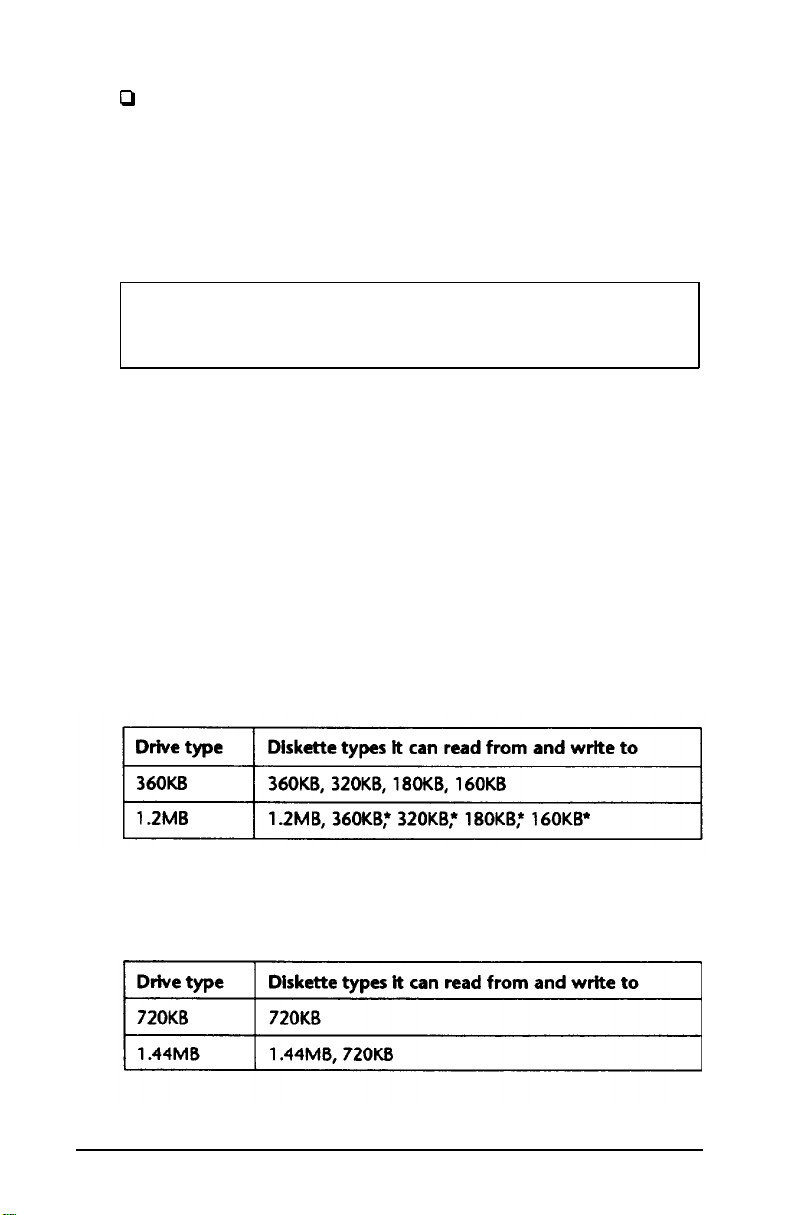
Drive and diskette incompatibilities
If your computer has more than one type of diskette drive, or
if you use different types of diskettes, you need to be aware of
certain incompatibilities between the drives and diskettes.
Because of the type and size differences, you cannot use a
31/2-inch
diskette
in a 51/4inch drive or vice versa. There are
also limitations on using diskettes that are the same size as
the drive but have different capacities. The following tables
summarize the possibilities and limitations.
5 1/4-inch drive/diskette compatibility
l If you write to this diskette in a 1 .2MB drive, you may not be able
to read it or write to it in a 360KB drive later.
3 1/2-inch
drive/diskette compatibility
Using Your Computer
3-9
Page 62

Because of these incompatibilities, always indicate the
diskette type and density when you label your diskettes.
(Usually this information appears on the manufacturer’s
label.)
If you have any combination of the above drives (1.44 MB,
1.2MB, 720KB, or 360KB), you can copy files from one drive
to another-using COPY or XCOPY-as long as the correct
diskette type is in each drive. You can also use these
commands to copy files between a hard disk and any type of
diskette. However, you cannot use the MS-DOS DISKCOPY
command to copy from one diskette drive to another if the
two drives are not the same type. For more about copying
files and diskettes, see your MS-DOS manuals.
Caring for Diskettes and Diskette Drives
Follow these basic precautions to protect your diskettes and
avoid losing data:
3
If you have a diskette that contains data you don’t want
to accidentally write over or erase, be sure you write-
protect it. This is especially important for your operating
system and application program diskettes. See “Writeprotecting Diskettes,” below, for more details.
a
a
a
a
3-10
Do not remove a diskette from the diskette drive or reset
or turn off the computer while the drive light is on. This
light indicates that the computer is copying data to or
from a diskette. If you interrupt this process, you can
destroy data.
Remove all diskettes before you turn off the computer.
Keep diskettes away from dust and dirt. Small particles of
dust or dirt can scratch the magnetic surface, destroy
data, and ruin the read/write heads in a diskette drive.
Never wipe, brush, or try to dean diskettes in any way.
Using Your Computer
Page 63

0
Keep diskettes in a moderate environment. Don’t leave
diskettes sitting in the sun, or in extreme cold or heat.
0
Keep diskettes away from magnetic fields, such as
electrical appliances, telephones, and loudspeakers.
(Remember that diskettes store information
magnetically.)
Q
Do not place diskettes on top of your monitor or near an
external hard disk drive.
Q
Always hold a 51/4-inch diskette by its protective jacket
and never touch the magnetic surface (exposed by the
read/write slot). The oils on your fingertips can damage
it.
0
Do not place anything on top of your diskettes, and be
sure they do not get bent.
0
Carefully label your diskettes and indicate the type and
density. Attach the label only along the top of a diskette
(next to the manufacturer’s label). Do not stick several
labels on top of one another; this can make it difficult to
insert and remove the diskette in the drive.
P
Write on a diskette label before you attach it to the
diskette. If you need to write on a label that is already on
the diskette, use only a soft-tip pen-not a ballpoint pen
or a pencil.
Q
Store diskettes in their protective envelopes and in a
proper location, such as a diskette container. Do not store
diskettes flat or stack them on top of each other.
Using Your Computer
3-11
Page 64

Write-protecting Diskettes
You can write-protect a diskette to prevent its data from
being altered. When a diskette is write-protected, you can
read it and copy data from it, but you cannot store new data
on it or delete any files it contains. If you try to change data
stored on a write-protected diskette, MS-DOS displays an
error message.
To write-protect a 51/4-inch diskette, cover the small,
rectangular notch (shown below) with an adhesive writeprotect tab. Write-protect tabs usually are included in a new
package of blank 51/4-inch diskettes.
To remove the write protection, peel off the write-protect tab.
3-12
Using
Your Computer
Page 65

On a 3M-inch diskette, the write-protect device is a small
switch on the back of the diskette in the lower right comer,
shown below. To write-protect a 3M-inch diskette, slide the
switch toward the edge of the diskette until it clicks into
position, exposing a hole in the comer.
-write-protect switch
To remove the write protection, slide the switch toward the
center of the diskette until it clicks into position and the hole
is covered.
Note
Some program diskettes have no notch or switch so they
are permanently write-protected. This protects them from
being accidentally erased or altered.
Using Your Computer
3-13
Page 66

Using a Single Diskette Drive System
MS-DOS expects the computer to have at least two diskette
drives and displays prompts and messages accordingly.
Usually, MS-DOS recognizes the first diskette drive (the top
drive) as A and a second diskette drive as B. If you have only
one diskette drive, MS-DOS can treat it as both A and B when
you need to perform operations that normally require two
diskette drives.
For example, if you enter a command to copy data from A
to B, MS-DOS copies the data from the first diskette you place
in the drive (which would be drive A) to the computer’s
memory. Then MS-DOS prompts you to insert another
diskette (for drive B) and copies the data from memory to the
new diskette. When copying is complete, you see a prompt to
insert the original diskette (A).
Because you may often swap diskettes this way, it is
important to remember which diskette is which. It is also a
good idea to write-protect your original diskette. See “Writeprotecting Diskettes,” above.
If you have a hard disk and one diskette drive, you can load
the operating system and application programs from the
hard disk, create and store your data there, and use the
diskette drive just for copying data to or from diskettes.
However, if you have only one diskette drive and no hard
disk, you need to use that drive to load the operating system
as well as any application program you are using. First, insert
the operating system diskette (the Startup diskette, for
example) in drive A and load the operating system; this
copies it to the computer’s memory (RAM) so you do not
need to leave the system diskette in the drive. Then remove
the system diskette and insert your application program
diskette to load that data into memory, too. See your
application program manual for detailed instructions.
3-14
Using Your Computer
Page 67

You can load MS-DOS from an application program
diskette if that diskette contains the operating system This
means it is a bootable diskette. See your MS-DOS manuals
for information about creating a system diskette.
Inserting and Removing Diskettes
If you have a 51/4-inch diskette drive, insert a diskette as
follows: hold the diskette with the label facing up and the
read/write slot leading into the drive, as shown below.
slot
Slide the diskette into the slot until it is in all the way. Then
turn the latch down to lock it in a vertical position. This
keeps the diskette in place and enables the read/write heads
in the drive to access the diskette.
When you want to remove a diskette, first make sure the disk
drive light is off. Then flip up the latch and carefully pull out
the diskette. Place it in its protective envelope and store it in
a proper location, such as a diskette container.
Using Your Computer
3-15
Page 68

If you have a 3 1/2-inch diskette drive, insert the diskette with
the label facing up and the metal shutter leading into the
drive, as shown in the following illustration. Slide the
diskette into the drive until it clicks into place.
When you want to remove the diskette, make sure the drive
light is off; then press the release button. When the diskette
pops out, remove it and store it properly.
Caution
Never remove a diskette or reset or turn off the computer
while a diskette drive light is on. You could lose data. Also,
be sure to remove all diskettes before you turn off the
computer.
3-16
Using Your Computer
Page 69

Formatting Diskettes
Before you can store data on a new diskette, you must format
it using the FORMAT command. Formatting prepares the
diskette so that MS-DOS can write data on it. You need to do
this only once, before you use the diskette for the first time.
You can also reformat previously used diskettes to store new
data. This process erases all the data on the diskette, so be
sure you do not want to save any of the files on a used
diskette before you format it. See your MS-DOS manuals for
instructions on using the FORMAT command.
Making Backup Copies
It is important to make copies of all your data and system
diskettes. Make backup (or working) copies of all diskettes
that contain programs, such as your MS-DOS, Reference, and
Utility diskettes; then use only the copies. Store the original
diskettes away from your working diskettes. Also, copy your
data diskettes regularly, whenever you revise them and store
them away from your originals.
If you have a hard disk, you’ll probably use it to store the
programs and data files you use regularly. Keep backup copies
of all your files on diskettes.
You can copy your data in several ways. See your MS-DOS
manuals for instructions on using the following commands:
0
You can use the COPY or XCOPY command to copy
individual files or groups of files.
0
You can use the DISKCOPY command to make an exact
duplicate of a diskette.
0
You can use the BACKUP command to back up hard disk
files to diskettes. Because BACKUP can split large files
across two or more diskettes, it makes more efficient use
of diskette space than COPY or XCOPY.
Using Your Computer
3-17
Page 70

Using a Hard Disk Drive
Using a hard disk is similar to using a diskette. However, the
hard disk provides several advantages:
cl
A 40MB hard disk can store as much data as
approximately thirty-three 1.2MB diskettes, and a 100MB
hard disk can store as much data as approximately
eighty-two 1.2MB diskettes.
D
Your computer can perform all disk-related operations
faster.
Cl
You can store frequently used programs and data files on
the hard disk, eliminating the inconvenience of swapping
diskettes to access different files.
The added storage capacity makes it easy to move back and
forth between different programs and data files. However,
because it is so easy to add programs and files to your hard
disk, you may find yourself trying to organize hundreds of
files.
MS-DOS lets you keep related files together in directories and
subdirectories so they are easy to find and use. See your
MS-DOS manuals for instructions on managing your files and
directories.
A hard disk must be partitioned and formatted before you
can use it. Be sure you have performed the procedures in
your MS-DOS manuals to prepare your hard disk for use.
Backing
up
the hard disk
While the hard disk is very reliable, it is essential to back up
your hard disk files to diskettes in case you lose some data
accidentally. Make copies of all your system and application
program diskettes before copying the programs to the hard
disk. After you create data files on the hard disk, be sure to
copy them to diskettes whenever you revise them to keep
your backup diskettes up-to-date.
3-18
Using Your Computer
Page 71

Caring for your hard disk drive
Follow these precautions to protect your hard disk drive from
damage and to avoid losing data:
Never turn off or reset the computer when the hard disk
access light is on. This light indicates that the computer
is copying data to or from the hard disk. If you interrupt
this process, you can lose data.
Never attempt to open the hard disk drive. The disk itself
is enclosed in a sealed container to protect it from dust.
Before you move your computer even a short distance,
you may need to run the HDSIT program to prepare the
hard disk for moving, as described below.
Preparing the hard disk for moving
If you need to move your computer to a new location, you
may want to run the HDSIT program-provided on your
Reference diskette-to protect the hard disk during the move.
HDSIT moves (or
parks)
the disk drive’s read/write heads to a
region on the disk surface that does not contain data, and
locks them securely in position. This protects the hard disk
from being damaged if the computer is bumped accidentally.
Many hard disk drives, induding all Epson drives,
automatically park their heads when you turn off the
computer. If your hard disk drive does not do this, or if you
are not sure that it does, be sure to run HDSIT.
Follow these steps to run HDSIT:
Insert the Reference diskette in drive A. Then type A : and
1.
press
Enter
Type the following and press
2.
HDSIT
to log onto that drive.
Enter:
Using Your Computer
3-19
Page 72

You see a message on the screen that tells you the disk drive’s
read/write heads will remain locked until you reset the
computer or turn the power off and on again. The computer
locks the heads and disables the keyboard. Remove any
diskettes and turn off the computer. You are now ready to
move it to the new location.
Note
For convenience, you may want to copy the following two
files from the Reference diskette to your hard disk:
HDSIT.COM
HDSIT.VER
Then, when you want to run HDSIT, just log onto the
directory on your hard disk where you stored the files,
type
H DS
IT, and press
Enter.
See your MS-DOS manuals for
instructions on using the COPY command.
If you have a 51/4-inch diskette drive and you still have the
original diskette drive protector card, you may want to insert
it into the drive prior to shipping your computer to protect
the read/write heads.
3-20
Using Your Computer
Page 73

Chapter 4
Enhancing System Operations
This chapter tells you how to use the following procedures to
enhance the operation of your computer:
Using AUTOEXEC.BAT and other batch files
0
Changing the processor speed
0
Using expanded memory beyond 640KB
Using the VGA utilities.
Using AUTOEXEC. BAT and Other Batch Files
As you get used to using MS-DOS and your application
programs, you may find that there are commands you need
to run frequently. You can automate the execution of these
commands by listing them in a special file called a batch file.
When you type the name of the batch file and press
MS-DOS executes the commands in the file just as if you had
typed each command from the keyboard.
Enter,
If you have a word processing program that can save a file as
a text-only file (sometimes called an ASCII file), you can use
it to create a batch file. You can also use the MS-DOS COPY
or EDLIN command, or a text editor, to create the file.
One batch file that you may find particularly useful is called
AUTOEXEC.BAT. Every time you turn on your computer,
MS-DOS looks for the AUTOEXEC.BAT file and automatically
executes each of the commands.
Enhancing System Operations
4-1
Page 74

When you install MS-DOS, it creates an AUTOEXEC.BAT file
for you. To modify the file or replace it with a new one, you
can use the COPY or EDLIN command, a text editor, or a
word processing program that can save a file as a text-only
file. However, be sure to name the file AUTOEXEC.BAT and
store it in the root directory of the hard disk or diskette from
which you load MS-DOS.
See your MS-DOS manuals for more information about
creating and using batch files.
Changing the Processor Speed
Your computer’s processor can operate at two speeds: high
and low. High speed is 20 MHz, low is 10 MHz. On high, the
computer can access memory faster than on low. Your
processor is set to operate at high speed (by default) in the
SETUP program unless you change the speed to low or set the
speed to change automatically.
NoteNote
When your computer is operating at high speed, theWhen your computer is operating at high speed, the
TURBO
TURBO
operating at low speed.operating at low speed.
light on the front panel is on, and it is off when
light on the front panel is on, and it is off when
You should use high speed for almost everything you do
since your programs will work faster. However, certain
application programs have specific timing requirements for
diskette access and can run only at the slower speed. See your
software manual to determine if this is the case.
Some copy-protected programs require the computer to run
at low speed while accessing the program on a diskette. These
programs also usually require you to leave a key disk-the
diskette that contains the copy protection-in the diskette
drive. If you use a copy-protected program often, you may
want to set your processor speed to change automatically to
low speed when accessing the diskette and return to high
speed when it is finished.
4-2
Enhancing System Operations
Page 75

There are different types of copy-protected programs.
Depending on the type you have, you may or may not want
to set the processor to automatic speed. Follow these
guidelines:
0
If you are using a copy-protected program that can run
only on a diskette or that requires a key disk, try to start
the program on high speed. If this works, you do not
need to set the speed to change automatically. If you
can’t load the program on high, set the speed to change
automatically.
0
If you are using a copy-protected program that does not
require a key disk but requires a special procedure to
install it on a hard disk, set the speed to low while you
are installing the program. Once it is installed, set the
speed to high, where you should be able to leave it while
you load and run the program.
If this does not work, try installing and loading the
program at low speed and then change to high speed to
run it. Do not set the speed to change automatically.
There are three ways to change the processor speed:
0
Run the SETUP program
0
Enter a keyboard command
0
Run the ESPEED program.
If you frequently use programs that require the processor to
operate at low speed or require the automatic speed change
when your computer is accessing a diskette, use SETUP to
change the processor speed. See Chapter 2 for instructions.
If you use these programs only occasionally, you should use
the keyboard commands or the ESPEED program (described
below) to change the processor speed.
Enhancing System Operations
4-3
Page 76

Entering Keyboard Commands
You can change the processor speed by entering one of the
commands shown in the following table.
Speed setting commands
To enter these commands, hold down the Ctrl key and the
Alt key simultaneously and then press the 2, +, 1, or - key.
Use the + or - key on the numeric keypad or the 1 or 2 key
on the main keyboard.
Note
You can use the commands listed above while you are
running a program. However, if the program uses one of
the same commands for another function, you cannot use
it to change the processor speed. For example, if you are
running a program that uses the Ctrl Alt - command to
move the cursor, you cannot enter Ctrl
processor speed to low. Another alternative is to use the
ESPEED program, described below.
Alt - to change the
The speed setting remains in effect until you press the RESET
button or turn off the computer, or until you change it again
using the SETUP program, another keyboard command, or
the ESPEED program.
4-4
Enhancing System Operations
Page 77

Using the ESPEED Program
ESPEED provides an easy way to change the processor speed
if your application program does not recognize the Cttl
keyboard commands or if you want to include the program
command in a batch file.
The ESPEED program is provided with your system on the
Reference diskette. If you do not have a hard disk, insert your
Reference diskette in drive A and log onto drive A before you
enter the command to start the program.
If you have a hard disk drive, copy the file ESPEED.COM
from your Reference diskette onto your hard disk and run the
program from there.
For information on how to run the ESPEED program, type
the following at the MS-DOS command prompt and press
Enter:
ESPEED ?
You see this display:
Format: ESPEED
No Parm : Displays current CPU Speed
H
L
?
The message tells you the switches you should use to
: Set to High Speed
: Set to Low Speed
: Help Message
set
the
speed to high or low. For example, to select low speed, type
the following and press
ESPEED L
Enter:
To change the processor speed back to high, enter this
command:
ESPEED H
Enhancing System Operations
4-5
Page 78

To display the current CPU speed,
press
Enter.
You see the following:
type ES P EED
only and
<+>
20.0 MHz <->
<Esc> : Exit
: Speed Up
: Speed Down
To change the speed when you see this display, press the +
or - key; then press
Esc
to exit.
The processor speed you set remains in effect until you
change it using the ESPEED program again, a keyboard
command, or the SETUP program; or until you press the
RESET
button or turn off the computer.
Entering the ESPEED command In a batch file
You may want to run the ESPEED program by including the
command in a batch file. For example, if you have a program
called SLOWDOWN which requires a slower processor speed,
you could include the following commands in a batch file to
start the SLOWDOWN program:
ESPEED L
SLOWDOWN
You could name the batch file SLOW.BAT. Whenever you
need to run the SLOWDOWN program, insert the program
diskette in drive A. Then type
SLOW
and press
Enter. The
computer changes the speed to low and starts the
SLOWDOWN program.
See your MS-DOS manuals for instructions on creating and
using batch files.
4-6
Enhancing System Operations
Page 79

Using Expanded Memory Beyond 640KB
The Equity 320sx PLUS comes with 2MB of random access
memory. MS-DOS and your application programs that run
under MS-DOS use the first 640KB of memory. You can use
any memory above 1MB as extended memory (up to 16MB)
or expanded memory (up to 24MB).
Shadow RAM uses 128KB of the RAM available between
640KB and 1MB in your system (384KB). If you use the
shadow RAM feature, 256KB of this memory is available for
use as extended or expanded memory. If you do not use
shadow RAM, you can use all of the 384KB of RAM as
extended memory but only 256KB of it as expanded memory
(to allow room for the expanded memory page frame).
Expanded memory is required by certain programs (such as
Lotus l-2-3) that support the Lotus/Intel/Microsoft Expanded
Memory Specification (LIM 4.0 EMS). To take advantage of
expanded memory, you need to use a memory manager to
convert the computer’s extended memory to expanded
memory. If you do not have another memory manager, you
can use the one provided on your Reference diskette,
EMM386SX.SYS. Follow the steps given below.
Note
Microsoft Windows comes with its own expanded memory
manager. Do not use EMM386SX.SYS (or the EMS Size
SETUP option) if you are installing Windows on your
system. See your Windows documentation for more
information.
1.
Run the SETUP program to allocate the amount of
memory you want to use as expanded memory. See “EMS
Size” in Chapter 2 for instructions.
2.
Copy the file EMM386SX.SYS from your Reference
diskette to the root directory of your hard disk (or the
Startup diskette).
Enhancing System Operations
4-7
Page 80

3.
Add a command to the CONFIG.SYS file to include the
memory manager as a device driver, as described in the
next section. The CONFIG.SYS file is used by MS-DOS to
set up the computer’s system configuration requirements.
Modifying the CONFIG.SYS File
If you have a word processing program that can save a file as
a text-only file (also called an ASCII file), you can use it to
add the memory manager to the CONFIG.SYS file. Follow
these steps:
1.
Start your word processing program.
2.
Load the file CONFIG.SYS and add the following
command line:
DEVICE-EMM386SX.SYS
For information on optional parameters, see “Using
EMM386SX.SYS options,” below.
Note
You can copy the FMM386SX.SYS file to a directory
other than the root directory as long as you either
enter that directory in a PATH command (for example,
in your AUTOEXEC.BAT file), or include the pathname
on the DEVICE= command line. For example, if
EMM386SX.SYS is in the directory \DRV on drive C,
include the pathname like this:
4-8
DEVICE-C:\DRV\EMM386SX.SYS
If you plan to use any of your expanded memory to
create a virtual disk with the MS-DOS VDISK device
driver, be sure to insert the EMM386SX.SYS command
line before the VDISK command line in your
CONFIG.SYS file. See your MS-DOS manuals for
information about VDISK.
Enhancing System Operations
Page 81

3.
Save the file as an ASCII text file.
4. Reset the computer.
If you do not have a word processing program capable of
saving an ASCII text file, you can modify CONFIG.SYS using
the MS-DOS EDLIN or COPY CON command, or a text
editor. See your MS-DOS manuals for instructions.
Using EMM386SXSYS options
You can include optional parameters in the DEVICE=
command line to tailor the way the memory manager works.
The table below summarizes the EMM386SX.SYS parameters.
EMM386SXSYS
parameters
The D parameter specifies whether you want EMM386SX.SYS
to run diagnostics on your expanded memory page frame
each time you load the program. It does not run the
diagnostics unless you include the D parameter.
Enhancing System
Operations
4-9
Page 82

The M[n] parameter specifies a particular 64KB page frame
address for EMM386SX.SYS. The value n must be a number
from 1 to 9 to indicate one of the following addresses:
l Default setting
For example, to specity a page frame address of 0CC000h,
add the following command line to your CONFIG.SYS file:
DEVICE-EMM386SX.SYS /M4
Note
If you have installed an EGA or VGA display adapter card,
you cannot enter the following values for n:
/Ml -Ml
/M2
-M2
The P[nnn] parameter specifies the number of handles (or
process IDS) available to EMM386SX.SYS. The value for nnn
must be in the range of 64 to 256. The default value is 64.
The X[nnnn-nnnn] parameter specifies a hexadecimal
memory address range to exclude from mapping by
Eh4M386SX.SYS. The first address (nnnn) is the beginning
address of the range and the second address (nnnn) is the
ending address.
4-10
Enhancing System Operations
Page 83

EMM386SX.SYS automatically excludes from mapping any
addresses that are reserved for use by your system ROM and
RAM. If you install an option card, such as a network card,
that uses the memory address range C000 through E000,
include the X parameter in the DEVICE= command line to
exclude this memory range from expanded memory
mapping.
For more information about your system’s memory, see
“System Memory Map” in Appendix A.
Using the VGA Utilities
Your built-in VGA (video graphics array) display adapter
supports both standard VGA monitors and multi-frequency
monitors with analog connectors. The VGA adapter operates
in all standard VGA resolutions without requiring any device
drivers. However, if you are using a monitor that supports
extended VGA features, you may want to use one or more of
the device drivers provided on the Utility diskettes that came
with your computer.
You need to install the VGA device drivers if you want to use
extended VGA features such as these:
D
Resolutions up to 800 x 600 in graphics modes with 16
colors
Q
132-column text mode in 16 colors
0
Graphics cursor movement performed by the built-in
VGA hardware.
Enhancing System Operations
4-11
Page 84

You can use the VGA utilities (also provided on the Utility
diskettes) to take advantage of other special features of your
VGA adapter. Even if you do not use any device drivers, you
may want to install some of the VGA utilities, such as the
following:
VGAMODE
SETVGA
Provides 132-column text in text-based
programs such as WordStar® and
WordPerfect.
@
Sets the built-in VGA adapter to emulate
the operation of other adapters, such as
Hercules@ and CGA adapters.
SNOOZE
Turns off your VGA display when you
have not used your computer for a
specified period of time.
The VGA device drivers and utilities are described in the VGA
Utilities booklet that came with your system.
4-12
Enhancing System Operations
Page 85

Chapter 5
Accessing Internal Components
To access your computer’s internal components, you need to
remove the cover and possibly the subassembly that contains
the drive bays and the power supply. Follow the instructions
in this chapter when you need to perform these steps:
Ll
Remove the computer’s cover
P
Remove the subassembly
D
Replace the subassembly
0
Replace the cover.
Be sure to heed all the cautions and warnings so you do not
injure yourself or damage the computer. If you have any
reservations about performing these steps yourself, ask your
Epson dealer for assistance.
drive. You do not need to remove it to install or remove an
Accessing Internal Components
5-1
Page 86

Removing the Cover
To access any internal components, you need to remove the
computer’s cover. Follow these steps:
1.
Turn off the computer and then any peripheral devices
(including the monitor and printer).
2.
Disconnect the computer’s power cable from the
electrical outlet and from the back panel. Then
disconnect any cables that are connected to the
computer, including the keyboard cable.
3.
If the monitor is on top of the computer, lift it off and set
it to one side.
4.
Turn the computer around so you are facing the back
panel. The cover is secured by a large screw on the back
panel, as shown below. Turn the screw counterclockwise
to unlock the cover.
screw
5-2
Accessing Internal Components
Page 87

5.
The cover is also secured by two latches on the back of
the cover near the comers. Press both latches inward and
then lift up the cover from the back panel. You might
meet some resistance from the g-rounding tabs along the
inside of the cover.
latches
6.
Pull the cover away from the front of the computer to
completely remove it. Then set it aside.
Accessing Internal Components
5-3
Page 88

7.
Before you touch any of the components, touch the
inside of the computer’s back panel, as shown below, to
ground yourself and avoid an electric shock.
WARNING
Be sure to ground yourself to the inside back panel of the
computer every time you remove the cover. If you are not
properly grounded, you could generate an electric shock
when you touch a component.
5-4 Accessing Intemal Components
Page 89

Removing the Subassembly
You need to remove the subassembly to install or remove
disk drives, or to access the SIMM or math coprocessor
sockets on your computer’s main system board. The
subassembly is the large metal casing that holds the
horizontal drive bays and the power supply, as shown below.
subassembly
Accessing Internal Components
5-5
Page 90

Follow these steps to remove the subassembly:
1.
Remove the front panel from the computer by lifting up
slightly on the three clips at the top of the panel and
tilting it toward you. Then set it aside.
clips
2.
If you have a hard disk drive, the drive cable is connected
to the main system board on the left side of the
subassembly, as shown below.
5-6
Accessing Internal Components
Page 91

Grasp the connector and pull it straight up to remove it
from the socket. Do not pull only on the cable.
3.
The diskette drive cable is connected to the socket behind
the hard disk drive socket; disconnect it in the same
manner.
4.
To lift the subassembly from the front of the computer,
place your thumbs under the diskette drive and grasp the
top edge of the computer with the rest of your fingers, as
shown in the following illustration. (If you have a
diskette drive installed in the lower horizontal drive bay,
place your thumbs underneath that drive instead.)
Accessing Internal Components
5-7
Page 92

5.
Raise the front of the subassembly, as shown below.
6.
Reach back underneath the subassembly and disconnect
the two power supply cables connected to the right side
of the main system board, as shown below. Pull each
connector straight up. Do not pull only on the cables.
5-8
-
Accessing Internal Components
Page 93

7.
Lift the entire subassembly out of the computer and
carefully place it on your work surface.
Replacing the Subassembly
Follow the steps below to replace the subassembly inside
your computer:
1.
Notice that there are four mounting slots on the back of
the subassembly: two in the upper comers and two in the
lower corners.
Accessing Internal Components
5-9
Page 94

There are four corresponding tabs on the inside back
panel of the computer which fit into the openings in the
subassembly slots.
tabs
Lift up the subassembly from your work surface and
lower the back end into the computer, guiding the top
slots on the subassembly into the top tabs on the
computer.
5-10
Accessing Internal Components
Page 95

2.
Hold up the front of the subassembly at a slight angle
and arrange the ribbon cables so they curve underneath
the subassembly and extend out its left side. Then grasp
the two power supply cables, labelled P4 and P5. Each
connector has six pin holes and a large tab on one side,
as shown below.
There is one 12-pin power supply socket on the right side
of the main system board (toward the back) that holds
both of the power supply connectors, as shown below.
Accessing Internal Components
5-11
Page 96

3.
Position power supply connector P4 so the large tab on
the connector faces the right side of the computer.
Beginning with the six pins toward the back of the
computer, carefully line up the holes in the connector
with the pins in the socket and then push in the
connector.
5-12
Caution
If you do not correctly align the holes with the pins in
the socket, you could severely damage your computer
when you push in the connector.
4.
Connect power supply connector PS to the remaining six
pins in the socket using the same procedure.
Accessing Internal Components
Page 97

Carefully lower the front of the subassembly onto the
5.
computer. Make sure that all four tabs on the back of the
computer are inserted into the slots on the subassembly
as you lower it.
small tabs
Accessing Internal Components
5-13
Page 98

Guide the tabs on the front of the subassembly over the
opening in the front of the computer so the two small
tabs sit behind the opening and the large tab with the
curved lip sits over the front of the opening. If necessary,
press on the large tab until the subassembly snaps into
place.
6.
Locate the hard disk drive and diskette drive ribbon
cables. (The hard disk drive cable is slightly longer than
the diskette drive cable.) Look at the back of each drive to
make sure you know which cable is which.
5-14
Accessing Internal Components
Page 99

Both the diskette drive and hard disk drive sockets are
located on the main system board on the left side of the
subassembly, as shown below.
Both sockets have a notch on one side. Connect the
diskette drive cable first. As shown below, there is a tab
on one side of the connector.
diskette drive connector
tab
diskette drive socket
Accessing Internal Components
5-15
Page 100

Align the connector with the socket so the tab on the
connector lines up with the notch in the socket. Make
sure the holes in the connector fit over all the pins in the
socket and then push in the connector.
Caution
If you do not correctly align the holes with the pins,
you could severely damage your computer when you
push in the connector.
7.
Now connect the hard disk drive cable in the same
manner.
8.
To replace the front panel, fit the three ridged tabs on its
bottom edge into the three notches on the lower edge of
the computer, as shown below.
5-16
tabs
9.
Tilt up the front panel until the clips on the top of the
panel touch the computer. Then push on the top of the
panel until it clicks into place.
Accessing Internal Components
 Loading...