

Page 1

®
EPSON EPL-N2700 Optional Units
SEPG98007
Page 2

Notice:
All rights reserved. No part of this manual may be reproduced, stored in a retrieval system, or transmitted in any form or by any means,
electronic, mechanical, photocopying, recording, or otherwise, without the prior written permission of SEIKO EPSON CORPORATION.
The contents of this manual are subject to change without notice.
All effort have been made to ensure the accuracy of the contents of this manual. However , shoul d any errors be detected, SEIKO EPSON
would greatly appreciate being informed of them.
The above not withstanding SEIKO EPSON CORPORATION can assume no responsibility for any errors in this manual or the consequences
thereof.
EPSON is a registered trademark of SEIKO EPSON CORPORATION.
General Notice: Other product names used herein are for identification purpose only and may be trademarks or registered trademar ks of their
respective owners. EPSON disclaims any and all rights in those marks.
Copyright © 1996 SEIKO EPSON CORPORATION. Printed in Japan.
Page 3

PREFACE
This manual describes basic functions, theory of el ectrical and mechanical operations, maintenance and repair procedures of EPSON EPL-N2700
Optional Units. The in struct ions a nd pr ocedures inc luded her ein ar e in tended for t he experienc ed r epair tec hnician s, and attenti on should be given to
the precautions on the preceding page. The chapters are organized as follows:
PCHAPTER 1. DOUBLE CASSETTE UNIT
Describes the step-by-step procedures for disassembling and assembling the
Double Cassette Unit.
CHAPTER 2. DUPLEX UNIT
Describes the step-by-step procedures for disassembling and assembling the
Duplex Unit.
CHAPTER 3. LCC UNIT
Describes the step-by-step procedures for disassembling and assembling the
LCC Unit.
CHAPTER 4. 5-BIN UNIT
Describes the step-by-step procedures for disassembling and assembling the 5Bin Unit.
CHAPTER 5. 10-BIN UNIT
Describes the step-by-step procedures for disassembling and assembling the
Double Cassette Unit.
CHAPTER 6. Operating Principles for Optional Units
Explains the operating principles of each optional unit.
Page 4

Revision Status
Revision Issued Date Description
A Fuburary 10, 1999 Revision A
Page 5

Contents
Double Cassette Unit
Installing the Doubl e Cassette Unit ................................................................. 9
Disassembly and Assembly of the Double Cassette Unit ............................... 11
Paper Take-up Roller Removal ........................................................................... 11
Paper Empty Sensor Removal ............................................................................ 11
Paper Near Empty Sensor Removal ................................................................... 12
Paper Feed Sensor Removal .............................................................................. 12
Paper Size Sensor (Paper Size Switch) Removal ............................................... 13
Controller Board (PWB-A) Removal .................................................................... 13
Paper Take-up Solenoid Removal ...................................................................... 14
Right Door Set Sensor Removal ......................................................................... 15
Maintenance of the Double Cassette Unit
Cleaning the Paper Take-up Roller .......... ............ ............................................... 16
Cleaning the Transport Roller ........ ..................................................................... 16
Exploded Diagrams for Double Cassette Unit
Housing ............................................................................................................... 17
Paper Take-up Section ........................................................................................ 19
Paper Tray Unit ................................................................................................... 21
...................................................... 16
................................................ 17
Duplex Unit
Installing the Dupl ex Unit .............................................................................. 24
Disassembly and Assembly of the Duplex Unit ............................................. 26
Duplex Unit Door Set Sensor Removal ............................................................... 26
Main Board Removal ........................................................................................... 27
Switch Back Motor Removal ............................................................................... 28
Transport Motor Removal .................................................................................... 29
Transport Roller Removal ................................................................................... 30
Maintenance of the Duplex Unit
Cleaning the Transport Roller ........ ..................................................................... 31
Exploded Diagrams for Duplex Unit
.................................................................... 31
.............................................................. 32
LCC Unit
Installing the LCC Unit .................................................................................. 35
Disassembly and Assembly of the LCC Unit
.................................................. 37
Separate Roller/Torque Limiter Removal ............................................................ 37
Feed Roller Removal .......... ............................................................... ................. 37
Paper Take-up Unit Removal ....................... .. .. .......... .. ....................................... 38
Lift-up Sensor Removal ...................................................................... 39
Paper Take-up Roller (Right) Assembly Removal .............................. 40
Right Paper Take-up Clutch Removal ................................................ 42
Paper Take-up Roller (Left) Assembly Removal ................................ 43
Paper Take-up Clutch (Left) Removal ................................................ 45
Paper Take-up Roller Removal .......................................................... 45
LCC Paper Take-up Sensor (PPS0) Removal ................................... 46
Paper Empty Sensor 1 (PPS1) Removal ........................................... 46
Paper Empty Sensor 2 (PPS2) Removal ........................................... 46
Paper Stand-by Position Sensor Removal ......................................... 47
Registration Sensor Removal ............................................................. 47
Side Cover Set Sensor Removal ........................................................ 48
Registration Clutch (RCL) Removal ................................................... 49
Separate Clutch Removal .................................................................. 49
Registration Roller Removal ............................................................... 51
Separate Roller Shaft Removal .......................................................... 51
Feed Roller Shaft Removal ................................................................ 51
Drive Section Disassembly ................................................................................. 52
LCC Transport Motor Removal .......................................................... 52
LCC Set Sensor Removal .................................................................. 53
Paper Near Empty Sensor Removal .................................................. 53
LCC Lift-up Motor Removal ................................................................ 54
LCC Main Board Removal .................................................................. 55
Paper Tray Unit Disassembly ............... .......... .. .................... .. .......... .. ................. 56
Roller with the Torque Limiter Removal ............................................. 56
Timing Belt Removal .......................................................................... 57
Lifter Drive Shaft Removal ................................................................. 59
Maintenance of the LCC Unit ......................................................................... 60
Maintenance Items .............................................................................................. 60
Cleaning the Paper Take-up Roller ..................................................................... 60
Cleaning the Feed/Separate Roller ..................................................................... 61
Cleaning the Vertical Transport Roller / Roller (Driven) ...................................... 61
Cleaning the Roller with a Torque Limiter ........................................................... 62
Page 6

Exploded Diagrams for LCC Unit ................................................................... 63
Housing ............................................................................................................... 63
Paper Take-up Section (A) .................................................................................. 65
Paper Take-up Section (B) .................................................................................. 67
Drive Section ....................................................................................................... 69
Paper Tray Unit (A) ............................................................................................. 71
Paper Tray Unit (B) ............................................................................................. 73
5-Bin Unit
Installing the 5- Bin Unit ................................................................................. 76
Disassembly and Assembly of the 5-Bin Unit ................................................ 80
Front Cover Removal .......................................................................................... 80
Rear Cover Removal ........................................................................................... 80
Jammed Paper Remove Door Removal .............................................................. 80
Shift Motor (M2) Removal ................................................................................... 81
Guide Position Sensor (PC3) Removal ............................................................... 82
Control Board (PWB-A) Removal ........................................................................ 82
Bin 4/ Bin 5 Switch Solenoid (SL2) Re moval ............ ....................... ................... 83
Jammed Paper Remove Door Sensor (PC1) Removal ....................................... 84
Transport Motor (M1) Removal ........................................................................... 84
Paper Guide Drive Motor (M3) Removal ............................................................. 85
Transfer Switch Sol enoid (SL1) Removal ........... ............ .................... .. ............ .. 86
Paper Guide Home Position Sensor (PC2) Removal .......................................... 87
Bin 1 Shift Home Position Sensor (PC4) Removal .............................................. 88
Paper Empty Sensor Board (PWB-B/D1-3/E) Removal ...................................... 89
Eject Sensor Board (PWB-C) Removal ............................................................... 90
Shift Guide Plate Removal .................................................................................. 91
Eject Roller Shaft Removal ................................................................................. 92
Bin 1 Eject Roller Shaft Removal ....................................................... 92
Bin 2 Eject Roller Shaft Removal ....................................................... 92
Bin 3 - 5 Eject Roller Shaft Removal .................................................. 93
Movable Paper Guide Removal .......................................................................... 94
Transfer Switch Guide Lever Removal ................................................................ 95
Bin 4 /Bin 5 Switch Guide Lever Removal ........................................................... 95
Maintenance of the 5-Bin Unit
Maintenance Items .............................................................................................. 96
Cleaning the Paper Take-up Roller .......... ............ ............................................... 96
Exploded Diagrams for 5-Bin Unit
Housing ............................................................................................................... 96
Paper Exit Section ............................................................................................... 98
Paper Transport Section (A) .............................................................................. 100
Paper Transport Section (B) .............................................................................. 102
....................................................................... 96
................................................................. 96
Paper Transport Section (C) ............................................................................. 104
10-bin Unit
Installing the 10-bin Unit ............................................................................. 107
Installing the 10-bin Unit .................................................................................... 107
Levelness Adjustment of the 10-bin Unit ........................................................... 113
Disassembly and Assembly of the 10-bin Unit
Outer Cover Removal ....................................................................................... 114
Tray Section Disassembly/Assembly ................................................................ 115
Transport Motor (M1) Removal ........................................................ 115
Transport Motor Pulse Detection Switch (PC1) Removal ................ 116
Sorter Set Switch (S1) Removal ....................................................... 117
Controller Board (PWB-A) Removal ................................................. 117
Sort/Non-Sort Switch Solenoid (SL1) Removal . ............................... 118
Solenoid Assembly (SL2, SL3) Removal . ........................................ 118
Bin 1/Bin 6 Paper Empty Sensor Board Removal (PWB-B/D5) ....... 119
Paper Empty Sensor Board (PWB-D1-D4, D6-D9) Removal ........... 120
Eject Sensor Board (PWB-C) Removal ............................................ 121
Vertical Transport Roller Removal ................................................... 122
Eject Roller Removal ........................................................................ 123
Bin Switch Guide Removal ............................................................... 124
Eject Guide Removal ........................................................................ 125
Sort/Non-Sort Switch Guide Removal .............................................. 126
Transport Roller Removal ................................................................ 127
Horizontal Transport Unit Disassembly/Assembly ............................................ 128
Rear Cover Removal ........................................................................ 128
Non-Sort Bin Jam Sensor (PC1) Removal ....................................... 128
Horizontal Transport Door Sensor (PC4) Removal .......................... 129
Horizontal Transport Unit Paper Empty Sensor (PC6) Removal ...... 129
Paper Path Switch Solenoid Removal .............................................. 130
Horizontal Transport Roller Removal ............................................... 131
Adjustment ................................................................................................. 132
Timing Belt Tension Adjustment ....................................................................... 132
Test Mode ......................................................................................................... 132
Pre-Operation ................................................................................... 132
Activating the Test Mode .................................................................. 133
Cancelling the Test Mode ................................................................. 133
Details of Each Test Mode ............................................................... 133
Adjusting the Eject Sensor ................................................................................ 139
Maintenance
............................................................................................... 140
............................................. 114
Page 7

Maintenance Items ............................................................................................ 140
Cleaning the Paper Take-up Roller .......... ............ ............................................. 140
Exploded Diagrams
Housing ............................................................................................................. 141
Frames .............................................................................................................. 143
Paper Transportation Section (A) ...................................................................... 145
Paper Transportation Section (B) ...................................................................... 147
Paper Transportation Section (C) ...................................................................... 149
Paper Transportation Section (D) ...................................................................... 151
Paper Transportation Section (E) ...................................................................... 153
Drive Section ..................................................................................................... 155
Horizontal Transport Unit (A) ............................................................................. 157
Horizontal Transport Unit (B) ............................................................................. 159
...... ............................ .................................................. 141
Operating principles
Double Cassette Unit ......... .............. ........................................................... 162
Structure ............................................................................................................ 162
Drive System .................................................................................... 162
Electrical Components Layout .......................................................... 162
Mechanical Operations ...................................................................................... 163
Paper Size Regulating Plate ............................................................ 163
Paper Lifting Plate ............................................................................ 163
Paper Size Setting ............................................................................ 163
Paper Near Empty Detection ............................................................ 164
Paper Empty Detection ................................................. .. ....... .......... 164
Paper Separation Mechanism .......................................................... 165
Paper Take-up Roller .......................... .. ..... .. ....... ..... ..... .. ..... ....... ..... 166
Paper Take-Up Retry Control ........................................................... 166
Duplex Unit ......... ....... ................................................................ ................. 167
Structure ............................................................................................................ 167
Drive System .................................................................................... 167
Electrical Components Layout .......................................................... 168
Mechanical Operations ...................................................................................... 168
Switchback Mechanism .................................................................... 168
Transport/Feedback Mechanism ...................................................... 169
Duplex Print Schemes ...................................................................... 170
LCC Unit Unit ................................................... ........................................... 172
Structure ............................................................................................................ 172
Drive System Layout ........................................................................ 172
Electrical Components Layout .......................................................... 173
Mechanical Operation ....................................................................................... 174
Vertical Transport Mechanism .......................................................... 174
Paper Take-up Mechanism .............................................................. 175
Paper Take-Up Retry Control ........................................................... 178
Paper Separating Mechanism .......................................................... 179
Paper Pressure Releasing Mechanism ............................................ 180
Paper Take-up Roller Retracting Mechanism . ................................. 180
Paper Size Regulating Plate ............................................................ 181
Paper Size Setting ............................................................................ 181
LCC Set Detection ............................................................................ 182
Lifting Mechanism ............................................................................ 183
Paper Near Empty Detection ............................................................ 185
Paper Empty Detection .................................................................... 185
5-Bin Unit ................................................................................................... 186
Structure ............................................................................................................ 186
Drive Section Layout ........................................................................ 186
Electrical Component Layout ........................................................... 187
Mechanical Operati ons ...................... .......... .......... ..................... .......... .......... .. 188
Paper Exit Path ................................................................................ 188
Single/Duplex Print Switch Mechanism ............................................ 189
Paper Guide Mechanism .................................................................. 189
Bin 4/Bin 5 Switch Mechanism ......................................................... 190
Shift Mechanism ............................................................................... 190
Paper Empty Detection Mechanism ................................................. 191
Paper Full Detection Mechanism . .................................................... 192
10-bin Unit .................................................................................................. 193
Structure ............................................................................................................ 193
Drive Section Layout ........................................................................ 194
Electrical Component Layout ........................................................... 195
Mechanical Operati ons ...................... .......... .......... ..................... .......... .......... .. 196
Paper Exit Path ................................................................................ 196
Paper Transport Mechanism (Horizontal Transport Unit) ................. 198
Bin Switch Mechanism ..................................................................... 198
Paper Empty Detection Mechanism ................................................. 199
Paper Full Detection Mechanism . .................................................... 199
Mode Description .............................................................................................. 200
Normal Mode (Non-Sort Mode) ........................................................ 200
Large Capacity Mode (Stacker Mode) .............................................. 200
Mailbox Mode ................................................................................... 200
Sorter Mode ........................................................................... .. ....... .. 200
Multiple Sorter Mode ........................................................................ 200
Page 8

DOUBLE CASSETTE UNIT
Page 9
EPL-N2700 Optional Units Revision A
1.1 Installing the Double Cassette Unit
This section describes how to install the Double Cassette Unit to the
printer main body. Note you are required to remove any optional unit
such as the Double Cassette Unit when servicing the printer. The
procedure for removing the Double Cassette Unit is not included since
you can remove it by reversing the installation procedure.
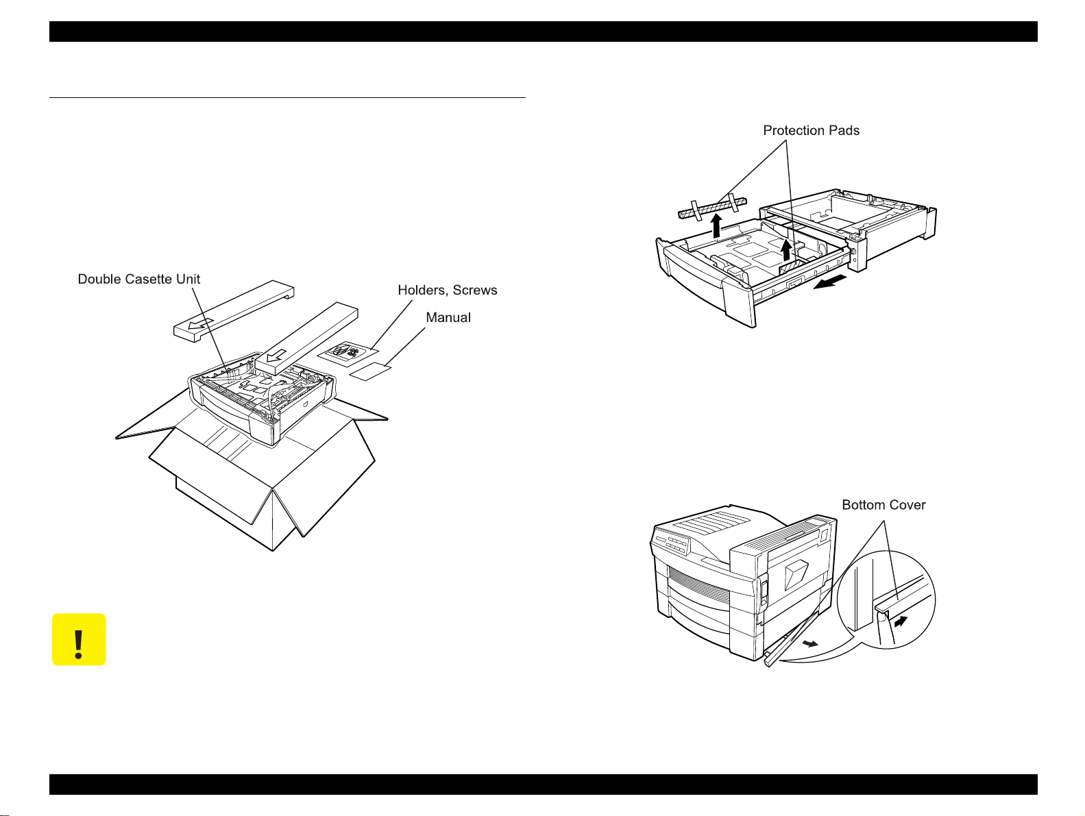
1. Open the packing carton and get a Double Cassette Unit and the
user’s manual.
2. Pull out the paper cassette and remove the protection materials.
Figure 1-2. Removing the Protection Pads
3. Turn the printer power off and disconnect the AC power cable and
interface cable.
4. Remove the bottom cover from the bottom part of the printer.
Figure 1-1. Unpacking
CAUTION
After removing the packing materials, please keep
them out of children’s reach.
Figure 1-3. Bottom Cover Removal
Double Cassette Unit Installing the Double Cassette Unit 9
Page 10
EPL-N2700 Optional Units Revision A
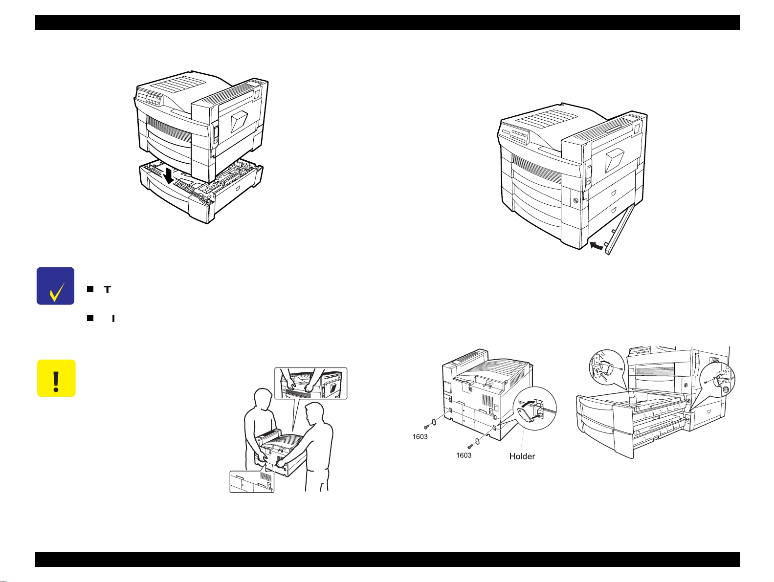
5. Place the printer main body on the Double Cassette Unit.
Figure 1-4. Placing the Printer on the Double Cassette Unit
CHECK
PO INT
When placing the printer, make sure the following:
The blue levers on the cassette and the printer are
facing in the same direction.
All corners of the printer are properly aligned with
the corresponding ones of the cassette unit.
6. Attache the bottom cover to the bottom part of the Double Cassette
Unit.
Figure 1-5. Installing the Bottom Cover
7. Secure the corners for t he printer and the Do uble Cassette Unit with
the holders and screws (1603).
CAUTION
2 people are required
to lift the printer as
shown in the figure.
Figure 1-6. Attaching the Holders
8. Connect the interface cable and the AC power cable to the printer
and turn the printer on.
Double Cassette Unit Installing the Double Cassette Unit 10
Page 11
EPL-N2700 Optional Units Revision A
1.2 Disassembly and Assembly of the Double Cassette Unit
This section provides the disassembly procedure for the Double
Cassette Unit. Unless otherwis e specified, assembly can be performed
by following the disassembly procedure in reverse order.
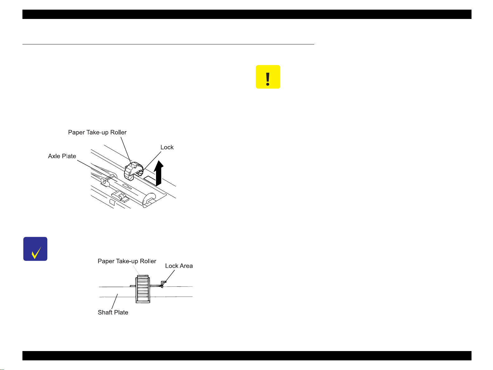
1.2.1 Paper Take-up Roller Removal
1. Release the lock on the Paper Take-up Roller and slide the roller
along the axle plate to remove the roller.
CAUTION
If you have replaced the Paper Take-up Roller, perform
“LC2 Counter Clear” in the maintenance menu. In case
2 Double Cassette Unit are connected, perform “LC3
Counter Clear” as well.
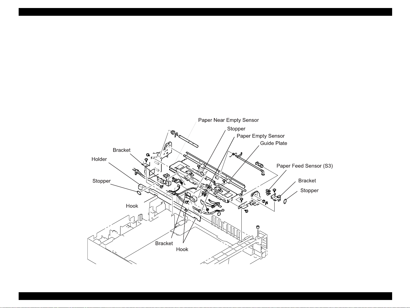
1.2.2 Paper Empty Sensor Removal
1. Release three hooks attaching the holder to the guide plate and
remove the holder. (See Figure 1-8.)
2. Remove the screw (3501) securing the paper empty sensor brack et
to the guide plate. (See Figure 1-8.)
3. Remove the stopper for the Paper Empty Sensor and remove the
sensor. (See Figure 1-8.)
4. Disconnect the harness from the Paper Empty Sensor.
Figure 1-7. Paper Take-up Roller Removal
CHECK
PO INT
When installing the Paper Take-up Roller, ensure the
roller is securely locked as shown in the figure below.
Double Cassette Unit Disassembly and Assembly of the Double Cassette Unit 11
Page 12
EPL-N2700 Optional Units Revision A
9302
3501
3704
3501
3501
3501
3704
9302
3501
S5
S4
3704
3704
1.2.3 Paper Near Empty Sensor Removal
1. Release three hooks attaching the holder to the gui de plate and
remove the holder.
2. Remove the screw (3501) securing the paper near empty sensor
bracket to the guide plate.
3. Remove the stopper for the Paper Near Empty Sensor and remove
the sensor.
4. Disconnect the harness from the Paper Near Empty Sensor.
1.2.4 Paper Feed Sensor Removal
1. Remove the screw (3501) securing the paper feed sensor bracket to
the guide plate and remove the bracket.
2. Remove the stopper for the Paper Feed Sensor and remove the
sensor.
3. Disconnect the harness from the Paper Feed sensor.
Figure 1-8. Removal of the Paper Empty / Paper Near Empty / Paper Feed Sensors
Double Cassette Unit Disassembly and Assembly of the Double Cassette Unit 12
Page 13
EPL-N2700 Optional Units Revision A
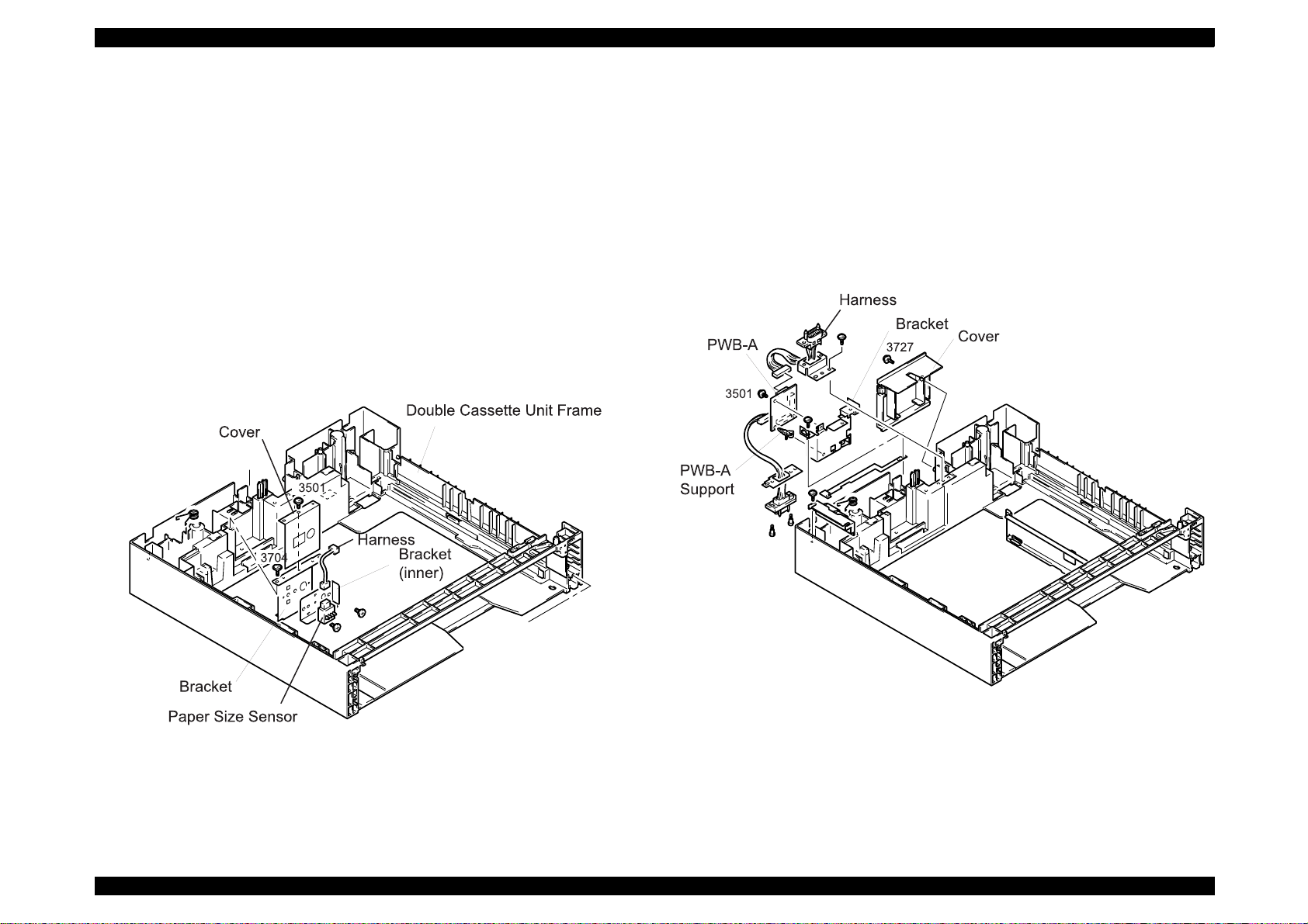
1.2.5 Paper Si ze Sensor (Paper Size Switch) Removal
1. Remove three screws (3704) securing the paper size sensor
bracket to the frame in the Double Cassette Unit, and remove the
bracket along with the paper size sensor.
2. Remove the screw (3501) securing the paper size sensor cover to
the bracket and remove the c ov er from the bracket .
3. Releas e the hook secur ing the Paper Size Sensor to the inner
bracket and remove the se ns or from the bracket.
4. Disconnect the harness from the Paper Size Sensor.
1.2.6 Controller Board (PWB-A) Removal
1. Remove the screw (3727) securing the cover and remove the cover.
2. Remove harnesses from the connectors on the PWB-A.
3. Remove two screws (3501) securing the PWB-A to the bracket and
the PWB s upport, and remov e the PWB-A.
Figure 1-10. PWB-A Removal
Figure 1-9. Paper Size Sensor Removal
Double Cassette Unit Disassembly and Assembly of the Double Cassette Unit 13
Page 14
EPL-N2700 Optional Units Revision A
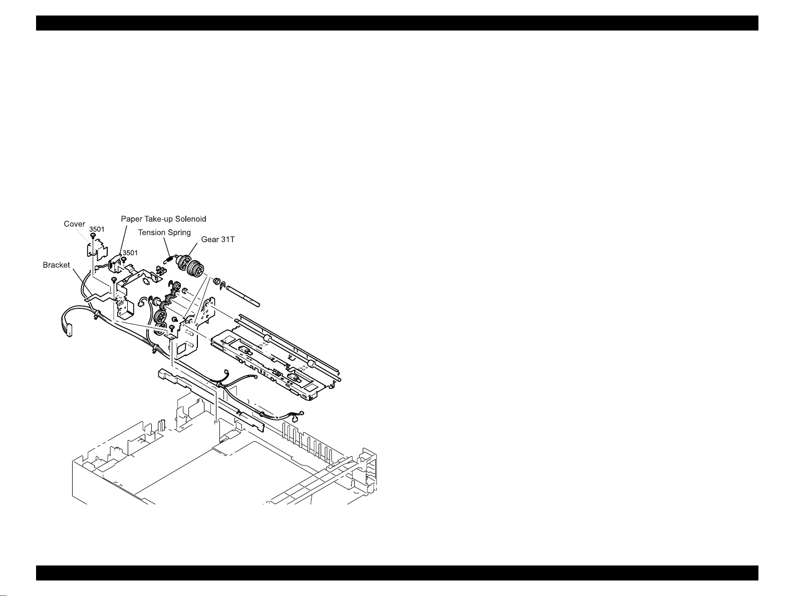
1.2.7 Paper Take-up Solenoid Removal
1. Remove the tension spring hooked to the gear 31T.
2. Remove the screw (3501) securing the paper take-up solenoi d
cover to the bracket and remove the cover.
3. Remove the screw (3501) securing the Paper Take-up Solenoid to
the bracket and remove the solenoid from the bracket.
4. Disconnect the harness from the connector on the solenoid.
Figure 1-11. Paper Take-up Solenoid Removal
Double Cassette Unit Disassembly and Assembly of the Double Cassette Unit 14
Page 15
EPL-N2700 Optional Units Revision A
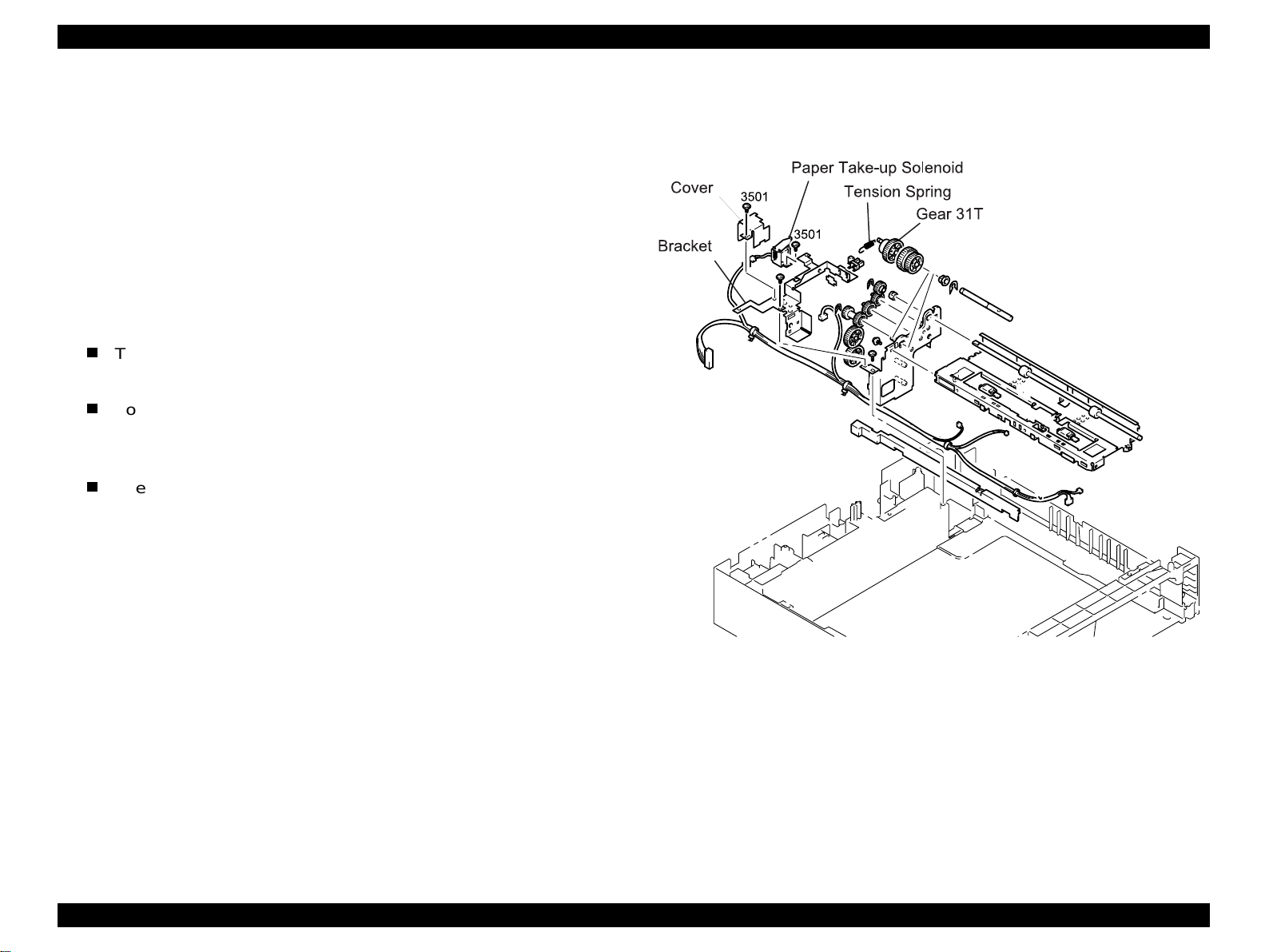
1.2.8 Right Door Set Sensor Removal
1. Remove the tension spring hooked to the gear 31T.
2. Remove two screws (3704) securing the PWB-A board bracket to
the Double Cassette Unit Frame and remove the bracket. (See
Section 1.2.7.)
3. Remove the screw (3501) securing the plate spring to the bracket
and remove the plate spring from the bracket.
4. Remove the following screws:
Two screws (3704) securing the solenoid bracket to the Double
Cassette Unit Frame.
Four screws (3704) securing the Paper Take-up Mechanism
(including the axle plate, guide plat e, and bracket) to the 2nd
Cassette Frame.
The screw (3501) securing the rail and axle plate.
5. Lift up the Paper Take-up Solenoid and bracket.
6. Remove two screws (3501) securing the solenoid bracket to the
Paper Take-up mechanism and remove the solenoid bracket.
7. Remove the stopper securing the Right Door Set Sensor to the
solenoid bracket.
8. Release the hook fixing the Right Door Set Sensor to the solenoid
bracket and remove the sensor.
9. Disconnect the harness from the connector on the Right Door Set
Sensor.
Figure 1-12. Right Door Set Sensor Removal
Double Cassette Unit Disassembly and Assembly of the Double Cassette Unit 15
Page 16
EPL-N2700 Optional Units Revision A
1.3 Maintenance of the Double Cassette Unit
The maintenance method of the Double Cassette Unit is mostly the
same as for the printer body. Therefore, this section only describes the
method specific to the Double Cassette Unit.
CAUTION
1.3.1 Cleaning the Paper Take-up Roller
1. Remove the Paper Take-up Roller. (Refer to Section 1.2.1.)
2. Wipe the Paper Take-up Roller with a soft cloth moistened with
water.
Do not use any solvent, including alcohol.
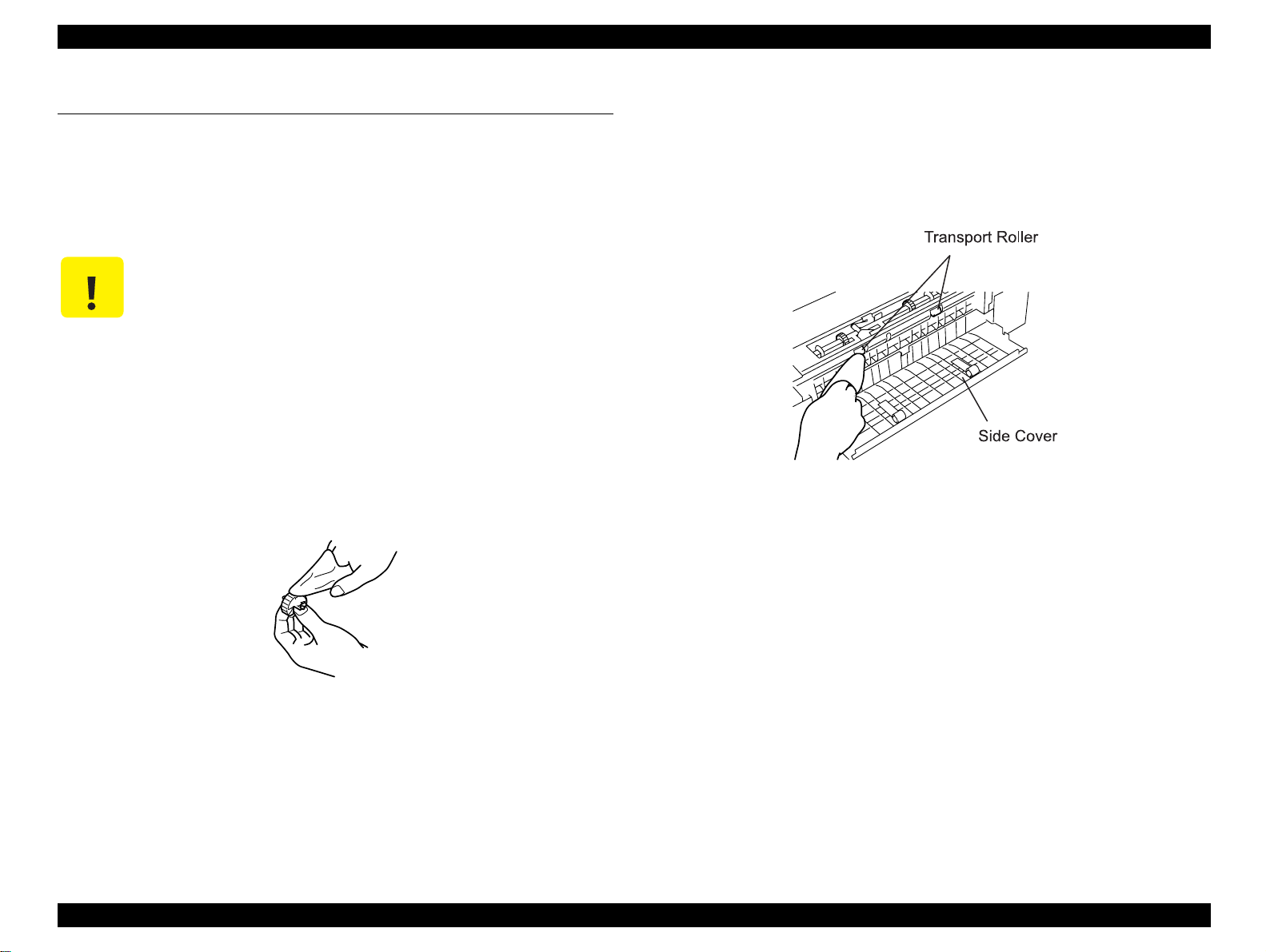
1.3.2 Cleaning the Transport Roller
1. Open the side cover.
2. Wipe the Transport Roller with a soft cloth moistened with water.
Figure 1-14. Cleaning the Transport Roller
Figure 1-13. Cleaning the Paper Take-up Roller
Double Cassette Unit Maintenance of the Double Cassette Unit 16
Page 17
EPL-N2700 Optional Units Revision A
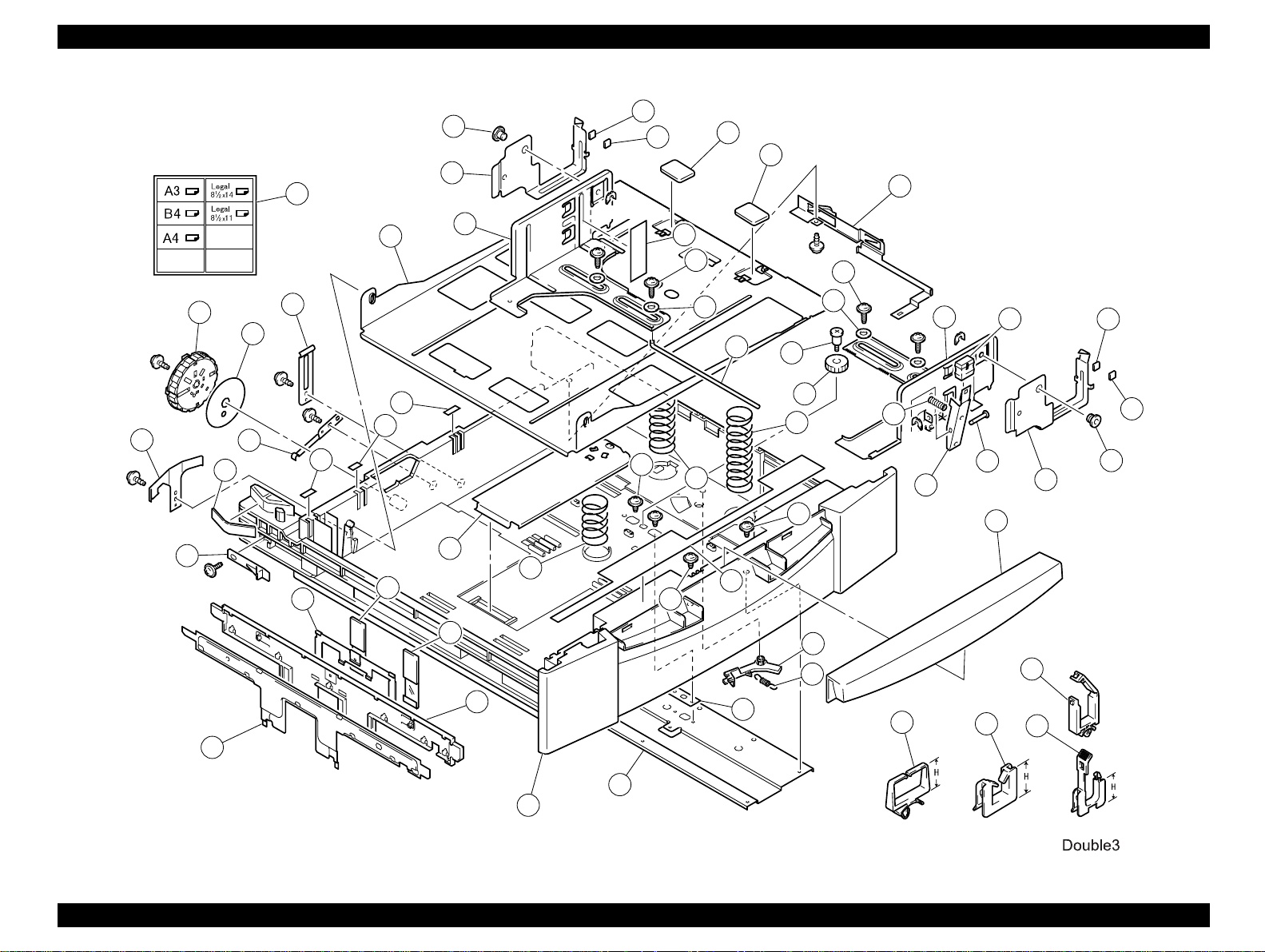
1.4 Exploded Diagrams for Double Cassette Unit
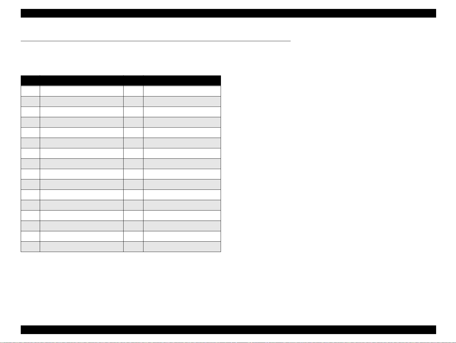
1.4.1 Housing
Table 1-1. Part List - Housing
No. Part Name No. Part Name
01 GUIDE 17 HOLDER
02 BRACKET 18 SPRING
03 PLATE SPRING 19 BRACKET
04 RUBBER FOOT 20 BRACKET
05 FRAME 21 SHOULDER SCREW
06 COVER 22 SWITCH, SIZE (S1)
07 GROUND PLATE 23 HARNESS
08 BRACKET 24 COVER
09 HARNESS 25 RUBBER FOOT
10 BRACKET 26 BRACKET
11 PW BOARD-A, MAIN (PWB-A) 27 BRACKET
12 PWB SUPPORT 6.35H 28 RAIL
13 HARNESS 29 PLATE SPRING
14 BRACKET 30 BRACKET
15 SHOULDER SCREW 31 HOLDER
16 RUBBER FOOT
− −
Double Cassette Unit Exploded Diagrams for Double Cassette Unit 17
Page 18
EPL-N2700 Optional Units Revision A
09
10
3704
08
3727
06
05
3501
03
01
11
3501
PWB-A
3704
04
02
07
12
3704
13
3704
14
3501
24
18
15
15
17
3704
23
22
19
31
1603
03
02
3501
3704
16
20
25
S1
21
3714
26
21
28
27
3704
3704
3714
3704
25
29
30
3704
Double Cassette Unit Exploded Diagrams for Double Cassette Unit 18
Page 19
EPL-N2700 Optional Units Revision A
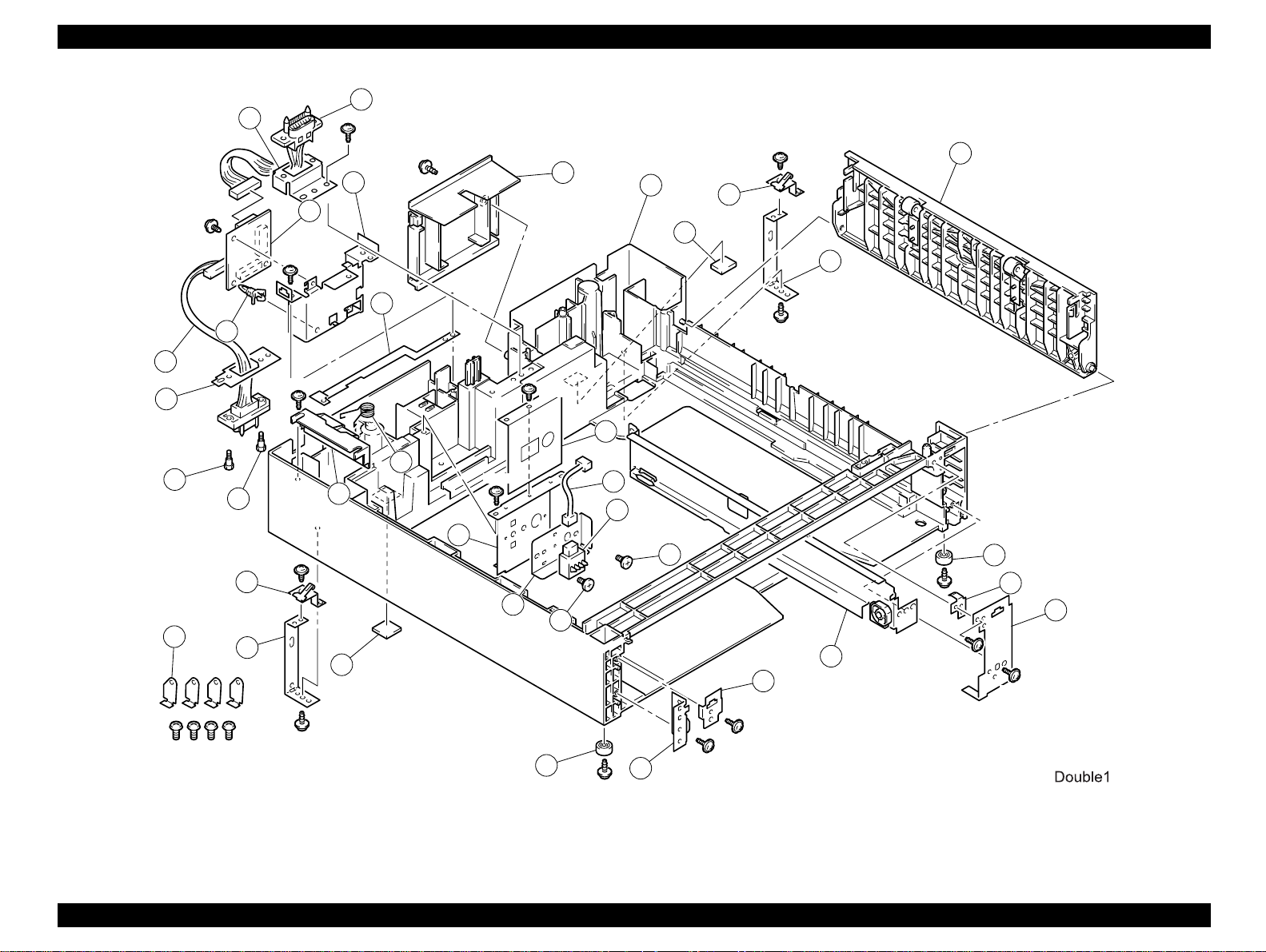
1.4.2 Paper Take-up Section
Table 1-2. Part List - Paper Take-up Section
No. Part Name No. Part Name
01 GUIDE PLATE 21 BUSHING
02 HOLDER 22 GEAR 34T
03 POLYESTER FILM 23 HARNESS
04 COLLAR 24 HOLDER
05 ROLLER 25 BRACKET
06 SHAFT 26 LEVER
07 AXLE PLATE 27 AXLE PLATE
08 ROLLER 28 SPACER
09 BUSHING 29 TORSION SPRING
10 GEAR 30/36T 30 BRACKET
11 GEAR 31T 31 TORSION SPRING
12 TENSION SPRINT 32 ACTUATOR
13 PHOTO INTERRUPTER (2S-5) 33 BRACKET
14 BRACKET 34 COLLAR
15 SOLENOID, TAKE-UP (SL1) 35 BRACKET
16 BRACKET 36 SHAFT
17 STOPPER 37 ACTUATOR
18 GEAR 16/20T 38 TORSION SPRING
19 GEAR 20T 39 GUIDE PLATE
20 GEAR 18T 40 GUIDE
Double Cassette Unit Exploded Diagrams for Double Cassette Unit 19
Page 20
EPL-N2700 Optional Units Revision A
3501
16
13
04
07
3704
03
40
38
28
32
02
05
05
3704
3501
37
40
33
21
34
04
01
S3
03
36
9302
02
13
3501
35
17
3501
SL1
15
3501
17
23
14
9301
17
18
S2
13
19
12
19
22
9302
24
20
22
3501
3704
11
25
21
S5
10
13
3501
27
1208
09
06
9302
08
39
28
3704
26
17
29
S4
30
3501
31
Double Cassette Unit Exploded Diagrams for Double Cassette Unit 20
Page 21

EPL-N2700 Optional Units Revision A
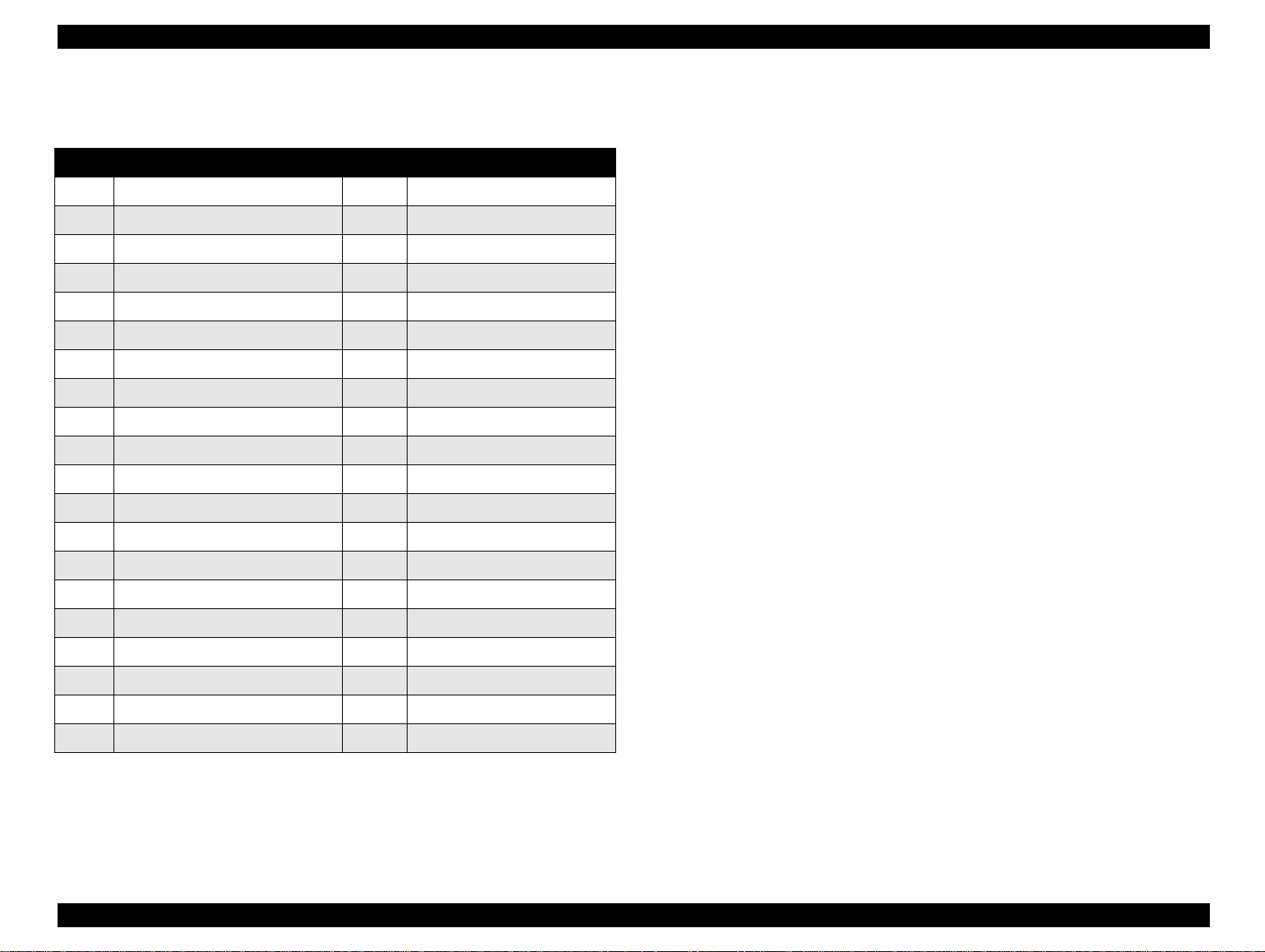
1.4.3 Paper Tray Unit
Table 1-3. Part List - Paper Tray Unit
No. Part Name No. Part Name No. Part Name
01 GROUND PLATE 18 STOPPER 35 SHOULDER SPRING
02 CORK 19 REINFORCE PLATE 36 SHAFT
03 COLLAR 20 PLATE SPRING 37 WASHER
04 HOLD PLATE 21 SHEET 38 SCREW
05 GUIDE PLATE 22 LIFTING PLATE 39 LABEL MAX LEVEL
06 REGULATING PLATE 23 PRESSURE SPRING 40 KNOB
07 LIFTING PLATE 24 REGULATING PLATE 41 REGULATING PLATE
08 LABEL PAPER SIZE 25 CASSETTE BODY 42 PRESSURE SPRING
09 PLATE SPRING 26 REINFORCE PLATE 43 LAVER
10 LABEL PAPER SIZE 27 SCREW 44 SHAFT
11 LEVER 28 PLATE 45 GUIDE PLATE
12 PLATE SPRING 29 TENSION SPRING 46 HANDLE
13 PLATE SPRING 30 LEVER 47 WIRING SADDLE 5.2H
14 FRICTION SHEET 31 LABEL CASSETTE 48 EDGE COVER 15.4H
15 LABEL 32 SCREW 49 EDGE COVER 8.5H
16 LABEL 33 PRESSURE SPRING 50 WIRE SADDLE 6.4H
17 LABEL 34 GEAR 14T
−−
Double Cassette Unit Exploded Diagrams for Double Cassette Unit 21
Page 22
EPL-N2700 Optional Units Revision A
12
3704
3704
18
11
3704
14
10
13
3704
3704
08
09
20
17
07
16
21
15
04
05
22
06
23
9302
03
32
03
27
39
38
33
37
02
31
36
02
35
33
27
3704
34
37
38
01
42
9303
43
41
9302
44
46
40
03
03
04
45
21
24
28
30
29
50
49
47
48
19
26
25
Double Cassette Unit Exploded Diagrams for Double Cassette Unit 22
Page 23

DUPLEX UNIT
Page 24
EPL-N2700 Optional Units Revision A
2.1 Installing the Duplex Unit
This section describes how to install the Duplex Unit to t he printer main
body. Note you are required to remove optional units such as the
Duplex Unit when servicing the printer. The procedure for removing the
Duplex Unit is not included since you can remove it by reversing the
installation procedure.
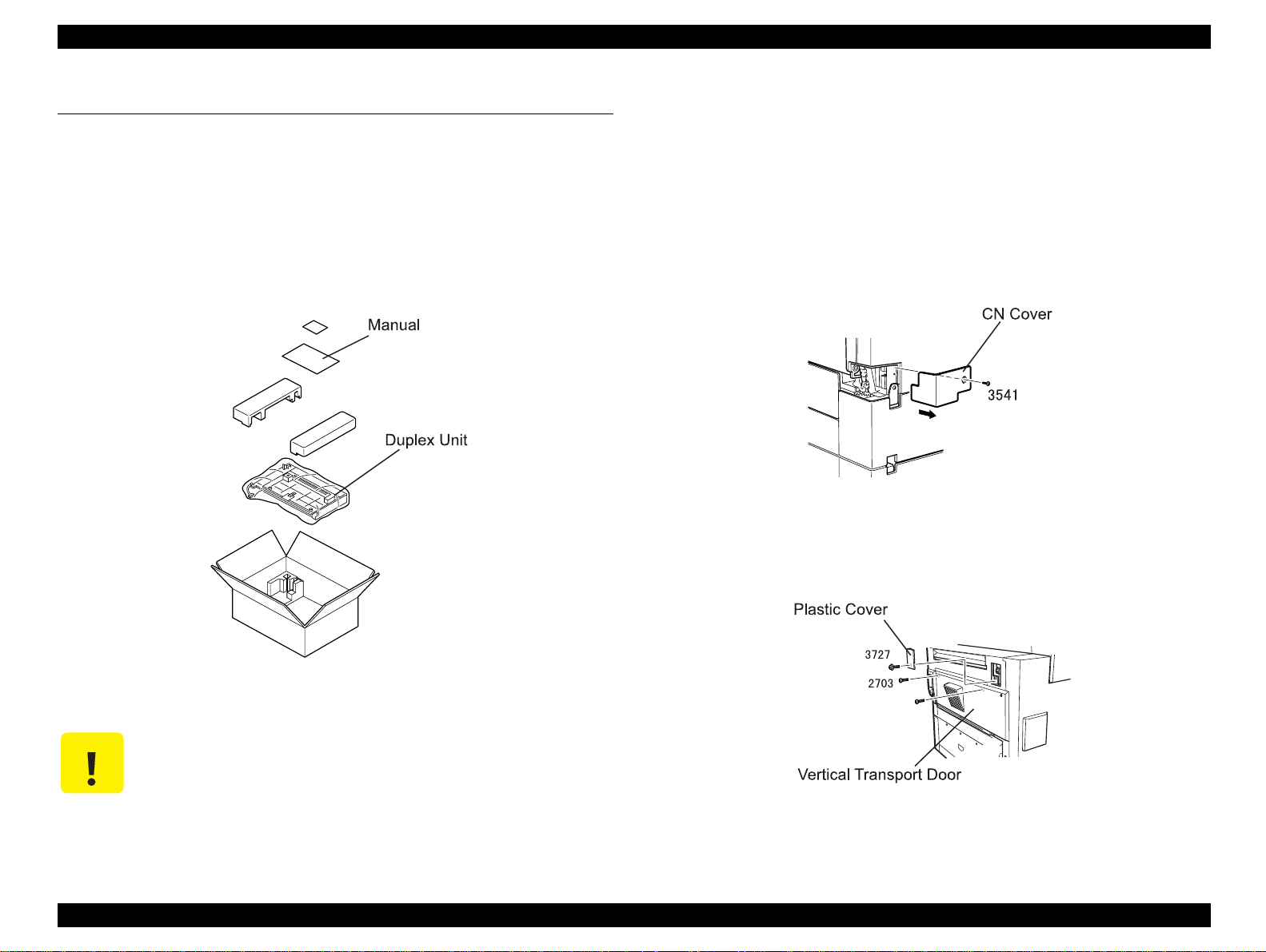
1. Open the packing carton and get a Duplex Unit and a user’s
manual.
2. Remove the protection materials and tapes from the Duplex Unit .
3. Turn the printer power off and disconnect the AC power cable and
interface cable.
4. Remove the plastic cover covering the harness connecti ng the
duplex unit to the printer main body.
5. Remove the screw (3541) securing the CN cover to the rear right
corner of the printer body and remove the CN cover.
Figure 2-2. CN Cover Removal
6. Remove the screw (3727) securing the gear cover to the f user cover
and remove the gear cover.
Figure 2-1. Unpacking
CAUTION
After removing the packing materials, please keep
them out of children’s reach.
Figure 2-3. Plastic Cover Removal
Duplex Unit Installing the Duplex Unit 24
Page 25
EPL-N2700 Optional Units Revision A
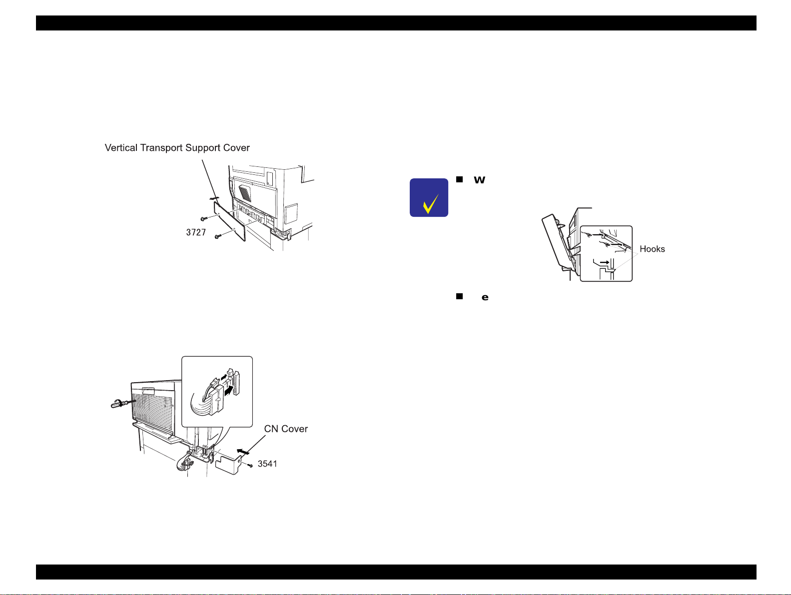
7. Remove two screws (2703) attached to the vertical trans port door.
8. Remove two screws (3727) securing the vertical trans port support
cover to the bottom part of the printer and remove the vertical
transport support cover.
Figure 2-4. Support Cover Removal
9. Using a phillips screw driver, secure the install the Duplex Unit to
the vertical transport door using two screws included with the
Duplex Unit.
10. Connect the harness from the Duplex Unit to the connector on the
printer main body.
11. Fasten three screws (3727) (attachment of the unit) to secure the
new sub cover included with the Duplex Unit to the printer.
12. Fasten the screw (3541) to fix the CN cover to the printer.
CHECK
PO INT
When placing the Duplex Unit, make sure two hooks
securely fit in the installation holes on the printer.
Before attaching the CN cover, make sure printer
connection harness is securely connected
13. Connect the interface cable and the AC power cable to the printer
and turn the printer on.
Figure 2-5. Duplex Unit Installation
Duplex Unit Installing the Duplex Unit 25
Page 26
EPL-N2700 Optional Units Revision A
2.2 Disassembly and Assembly of the Duplex Unit
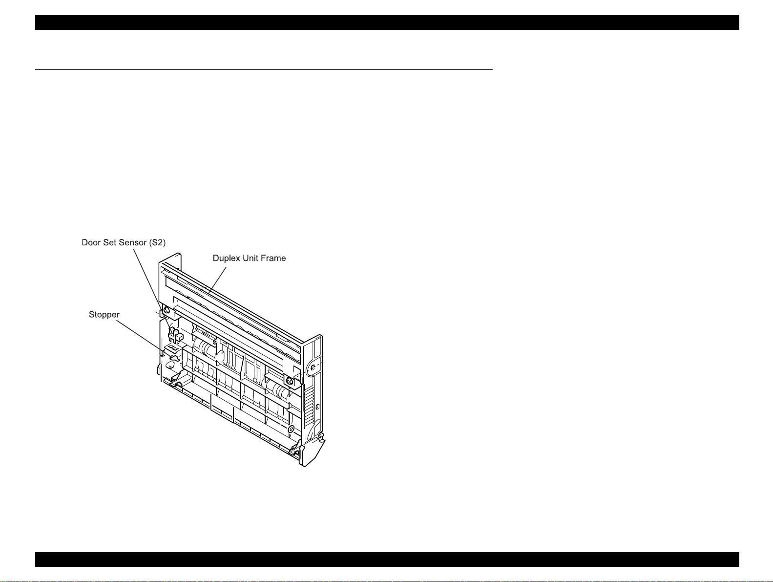
2.2.1 Duplex Unit Door Set Sensor Removal
1. Remove the Duplex Unit. (Refer to Section 2.1.)
2. Open the Duplex Unit Door.
3. Remove the stopper securing the door set sensor to the Duplex Unit
Frame and unhook the sensor from the frame.
4. Disconnect the harness from the connector on the sensor.
Figure 2-6. Paper Take-up Roller Removal
Duplex Unit Disassembly and Assembly of the Duplex Unit 26
Page 27
EPL-N2700 Optional Units Revision A
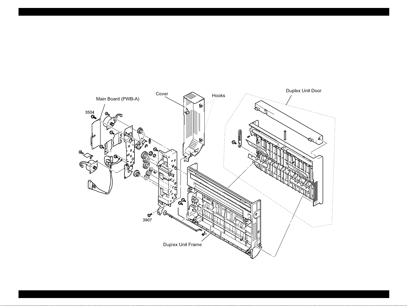
2.2.2 Main Board Removal
1. Remove the Duplex Unit. (Refer to Section 2.1.)
2. Remove two screws securing the cover to the Duplex Unit.
3. Open the Duplex Unit door and release two hooks securing the
cover to the Duplex Unit Frame, and remove the cover.
4. Disconnect the harness from the connector on the Main Board.
5. Remove two screws (3504) securing the Main Board to the Duplex
Unit and remove the Main Board.
Figure 2-7. Main Board Removal
Duplex Unit Disassembly and Assembly of the Duplex Unit 27
Page 28
EPL-N2700 Optional Units Revision A
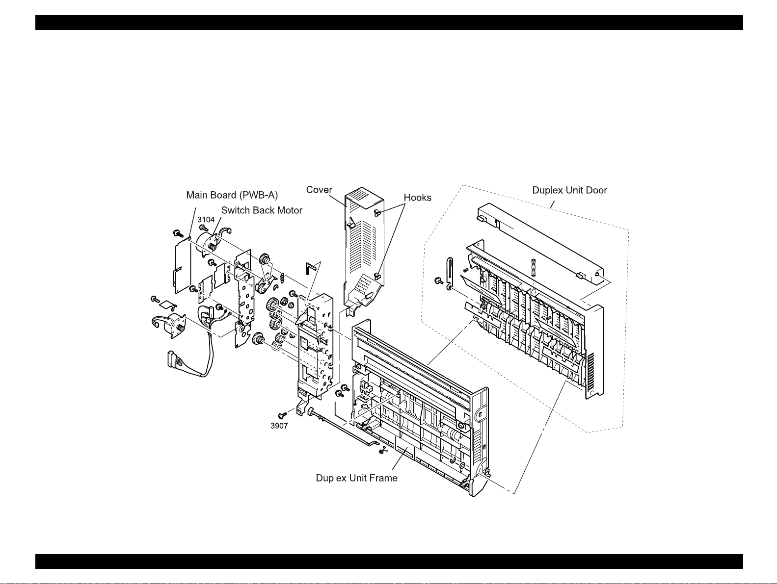
2.2.3 Switch Back Motor Removal
1. Remove the Duplex Unit. (Refer to Section 2.1.)
2. Remove two screws (3907) securing the cover to the Duplex Unit.
3. Open the Duplex Unit door and r elease two hook s fixing the cover to
the Duplex Unit frame. Then remove the cover.
4. Remove the harness for the Switch Back Motor from the connector
on the Main Board.
5. Remove two screws (3104) securing the Switch Back Motor to the
Duplex Unit and remove the Switch Back Motor.
Figure 2-8. Switch Back Motor Removal
Duplex Unit Disassembly and Assembly of the Duplex Unit 28
Page 29
EPL-N2700 Optional Units Revision A
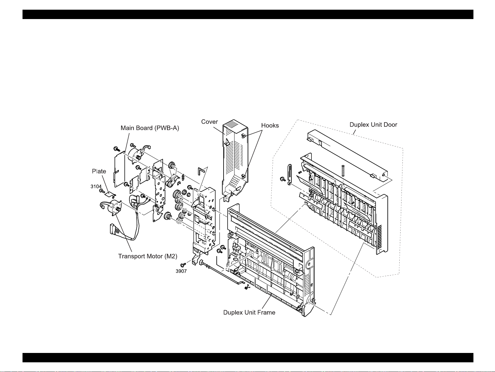
2.2.4 Transport Motor Removal
1. Remove the Duplex Unit. (Refer to Section 2.1.)
2. Remove two screws (3907) securing the cover to the Duplex Unit.
3. Open the Duplex Unit door and r elease two hook s fixing the cover to
the Duplex Unit frame. Then remove the cover.
4. Remove the harness for the Transport Motor from the connector on
the main aboard.
5. Remove two screws (3104) securing the Transport Motor to the
Duplex Unit and remove the Transport Motor and the plate.
Figure 2-9. Transport Motor Removal
Duplex Unit Disassembly and Assembly of the Duplex Unit 29
Page 30
EPL-N2700 Optional Units Revision A
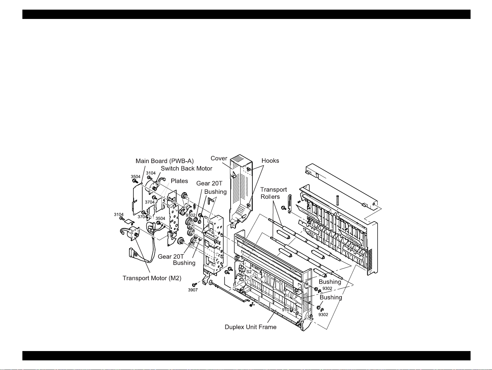
2.2.5 Transport Roller Removal
1. Remove the Duplex Unit. (Refer to Section 2.1.)
2. Remove two screws (3907) securing the cover to the Duplex Unit.
3. Open the Duplex Unit door and r elease two hook s fixing the cover to
the Duplex Unit frame. Then remove the cover.
4. Remove the Main Board. (Refer to Section 2.2.2.)
5. Remove the Switch Back Motor. (Refer to Section 2.2.3.)
6. Remove the Transport Motor. (Refer to Section 2.2.4.)
7. Remove the screw (3504) securing the ground cable to the axle
plate and remove the ground cable.
8. Remove three screws (3704) securing two plates to the holders
through the axel plate and remove the plates and the axel plate.
9. Release the hooks on the gears 20T attached to the Transport
Rollers and remove the gears 20T and the bushings.
10. Remove the E-ring (9302) from each transport roller shaft and
remove the bushing from the transport roller shaft.
11. Remove the Transport Rollers from the Duplex Unit.
Figure 2-10.
Transport Roller Removal
Duplex Unit Disassembly and Assembly of the Duplex Unit 30
Page 31

EPL-N2700 Optional Units Revision A
2.3 Maintenance of the Duplex Unit
The maintenance method of the Duplex Unit is mostly the same as for
the printer body. Therefore, this se ction only describes the method
specific to the Duplex Unit.
2.3.1 Cleaning the Transport Roller
1. Open the Duplex Unit door. (Refer to Section 2.2.1.)
2. Wipe the Transport Roller with a soft cloth moistened with water.
CAUTION
Do not use any solvent, including alcohol.
Figure 2-11. Cleaning the Transport Roller
Duplex Unit Maintenance of the Duplex Unit 31
Page 32

EPL-N2700 Optional Units Revision A
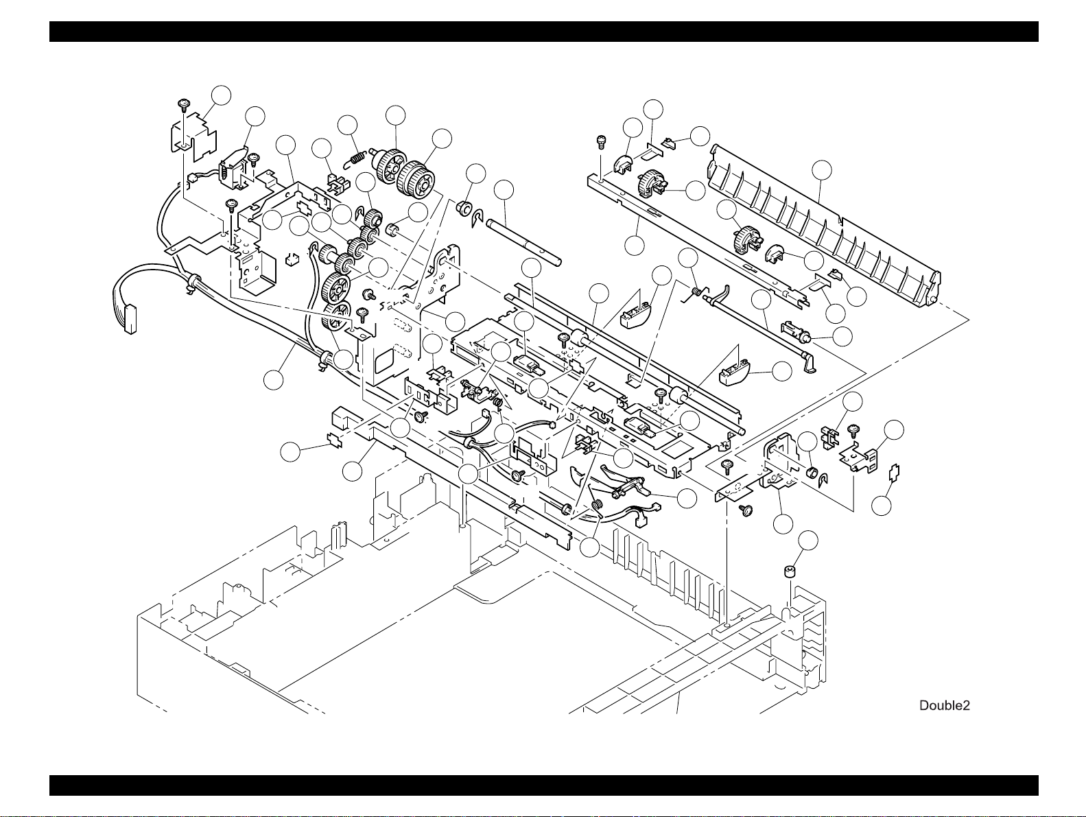
2.4 Exploded Diagrams for Duplex Unit
Table 2-1. Part List
No. Part Name No. Part Name
01 LEVER 20 PW BOARD-A, MAIN (PWB-A)
02 PRESSURE SPRING 21 PLATE
03 COVER 22 PLATE
04 PRESSURE SPRING 23 GEAR 35T
05 POLYESTER FILM 24 GEAR 24T
06 STOPPER 25 GEAR 17/45T
07 POLYESTER FILM 26 HARNESS
08 ROLLER 27 HOLDER
09 ROLL 28 SPRING
10 SHOULDER SCREW 29
11 COVER 30 STOPPER
12 SEAL 31 ACTUATOR
13 BUSHING 32 TORSION SPRING
14 GEAR 20T 33 FRAME
15 TENSION SPRING 34 COVER
16 LEVER 35 POLYESTER FILM
17 GEAR 12/40T 36 WASHER
18 AXLE PLATE 37 LABEL
19 MOTOR (M1, 2) - -
PHOTO INTERRUPTER,
DOOR SET (S2)
Duplex Unit Exploded Diagrams for Duplex Unit 32
Page 33

EPL-N2700 Optional Units Revision A
20
PWB-A
21
3104
3504
3704
M2
19
3104
22
19
M1
3704
3504
26
22
18
25
23
23
23
24
17
27
16
9302
3907
24
15
14
3704
14
12
13
13
31
28
11
3704
3704
28
30
32
S2
28
10
29
09
09
08
37
28
06
3704
9107
36
07
04
03
09
05
13
10
9302
9302
33
02
13
09
01
04
08
05
35
34
Duplex Unit Exploded Diagrams for Duplex Unit 33
Page 34

LCC UNIT
Page 35

EPL-N2700 Optional Units Revision A
3.1 Installing the LCC Unit
This section describes how to install the LCC Unit, or Large Capacity
Cassette Unit, to the printer main body. Note you are required to
remove optional units such as the LCC Unit when servicing the printer.
The procedure for removing the LCC Unit is not included since you can
remove it by reversing the install ation procedure.
1. Open the packing carton and get a LCC Unit, four pairs of holder
and screw, and a user’s manual.
2. Remove the protection materials and tapes from the LCC Unit.
Figure 3-2. Protection Material & Tape Removal
3. Remove the protection pads from the tray.
Figure 3-3. Protection Pad Removal
4. Shut the cassette in to the cabinet.
5. Turning the adjuster located at the front right corner of bottom part
of the LCC Unit, set the unit on the floor.
Figure 3-4. Fixing The LCC Unit
CAUTION
Figure 3-1. Unpacking
After removing the packing materials, please keep
them out of children’s reach.
LCC Unit Installing the LCC Unit 35
Page 36

EPL-N2700 Optional Units Revision A
6. Remove the bottom cover from the bottom part of the prin ter.
Figure 3-5. Bottom Cover Removal
7. Turn the printer power off and disconnec t the AC power cable and a
interface cable.
8. Place the printer on the LCC Unit.
CAUTION
Two people are required to lift the printer safely.
9. Secure the printer and the LCC Unit by each c orner using the holde r
and the screw (1603).
Figure 3-7. Securing the Printer to the LCC Unit
CHECK
PO INT
Figure 3-6. Placing the Printer on the LCC Unit
When placing the printer, make sure the blue
10. Connect the interface cable and the AC power cable to the printer
and turn the printer on.
handouts of the printer and the LCC Unit are al l facing
the same direction and all corners of the printer and
the LCC Unit are aligned.
LCC Unit Installing the LCC Unit 36
Page 37

EPL-N2700 Optional Units Revision A
3.2 Disassembly and Assembly of the LCC Unit
3.2.1 Separate Roller/Torque Limiter Removal
1. Open the side cover of the LCC Unit.
2. Remove the C-Ring from the separate roller shaft and re mov e the
Separate Roller first and then the Torque Limit er.
Figure 3-8. Separate Roller / Torque Limiter Removal
3.2.2 Feed Roller Removal
1. Open the side cover of the LCC Unit.
2. Remove the C-Ring from the feed roller shaft and remove the Feed
Roller.
Figure 3-9. Reed Roller Removal
CAUTION
Always replace the Feed Roller, Separate Roller, and
CAUTION
the Torque Limiter together since they have the same
length of life.
Always replace the Feed Roller, Separate Roller, and
the Torque Limiter together since they have the same
length of life.
LCC Unit Disassembly and Assembly of the LCC Unit 37
Page 38

EPL-N2700 Optional Units Revision A
3.2.3 Paper Take-up Unit Removal
1. Pull out the paper cassette.
2. Remove four screws (1723) securing the Paper Tray Unit to the
LCC Unit and remove the Paper Tray Unit.
Figure 3-10. Paper Tray Unit Removal
3. Release three connectors and code clump inside the unit and
remove the harness.
Figure 3-11. Harness Removal
4. Remove two screws (4021) securing the r ight co ver t o the LCC Unit
and remove the right cover.
Figure 3-12. Right Cover Removal
LCC Unit Disassembly and Assembly of the LCC Unit 38
Page 39

EPL-N2700 Optional Units Revision A
5. Remove the side cover.
6. Remove two screws (4012) securing the Paper Take-up Unit to the
LCC Unit and remove the Paper Take-up Unit.
Figure 3-13. Paper Take-up Unit Removal
3.2.3.1 Lift-up Sensor Removal
1. Remove the Paper Take-up Unit. (Refer to Section 3.2.3.)
2. Remove the stopper fixing the Lift-up Sensor to the Paper Take-up
Unit.
3. Push down the Paper Take-up Roller to release the actuator from
the sensor and remove the sensor.
4. Remove the harness from the connector on the sensor.
Figure 3-14. Lift-up Sensor Removal
LCC Unit Disassembly and Assembly of the LCC Unit 39
Page 40

EPL-N2700 Optional Units Revision A
3.2.3.2 Paper Take-up Roller (Right) Assembly Removal
1. Remove the Paper Take-up Unit. (Refer to Section 3.2.3.)
2. Remove the harness for the Lift-up Sensor. (Refer to Section
3.2.3.1.)
3. Remove the harness for the right paper take-up clutch.
4. Remove two springs on the Paper Take-up Roller Assembly.
6. Release the Paper Take-up Roller Assembly from the Paper Takeup Unit to loosen the timing belt, then remove the paper take-up
Roller Assembly.
Figure 3-16. Paper Take-up Roller Assembly (Right) Removal (2)
CHECK
PO INT
When installing the Paper Take-up Roller Assembly,
set the edge of the assembly to the indicated position
in the figure below.
Figure 3-15. Paper Take-up Roller (Right) Assembly Removal (1)
5. Remove the shoulder screw securing the Paper Take-up Roller
Assembly to the Paper Take-up Unit.
LCC Unit Disassembly and Assembly of the LCC Unit 40
Page 41

EPL-N2700 Optional Units Revision A
„
CAUTION
Always replace the Paper Take-up Roller 1 and 2
together since they have the same length of life.
„
When the Paper Take-up Roller in the LCC Unit is
replaced while 1 optional Double Cassette Unit is
connected, perform “LC3 Counter Clear” in the
maintenance mode. (See EPL-N2700 Service Manual /
Chapter 1.)
„
When the Paper Take-up Roller in the LCC Unit is
replaced while optional Double Cassette Unit is
disconnected, perform “LC2 Counter Clear” in the
maintenance mode. (See EPL-N2700 Service Manual /
Chapter 1.)
LCC Unit Disassembly and Assembly of the LCC Unit 41
Page 42

EPL-N2700 Optional Units Revision A
3.2.3.3 Right Paper Take-up Clutch Removal
1. Remove the Paper Take-up Unit. (Refer to Section 3.2.3.)
2. Remove the Paper Take-up Roller Assembly. (Refer to Section
3.2.3.2.)
3. Release the hook securing the Paper Take-up Clutch to the Paper
Take-up Roller Shaft and remove the clutch to the rear.
4. Disconnect the harness for the Paper Take-up Clutch from the
connector.
CHECK
PO INT
Be sure to hook th e cl u tch to the arm in the Paper
Take-up Unit as shown in the figure below.
Figure 3-17. Paper Take-up Clutch Removal
LCC Unit Disassembly and Assembly of the LCC Unit 42
Page 43

EPL-N2700 Optional Units Revision A
3.2.3.4 Paper Take-up Rol ler (Left) Assembly Removal
CHECK
PO INT
1. Remove the Paper Take-up Unit. (Refer to Section 3.2.3.)
2. Remove the harness for the Lift-up Sensor. (Refer to Section
3.2.3.1.)
3. Remove the harness for the Paper Take-up Clutch (Left).
4. Remove two springs on the Paper Take-up Roller Assembly.
Be sure to hook the clutch to the arm in the Paper
Take-up Unit.
5. Remove the shoulder screw securing the Paper Take-up Roller
Assembly to the Paper Take-up Unit.
6. Remove the Paper Take-up Roller Assembly.
Figure 3-19. Paper Take-up Roller(Left) Assembly Removal (2)
CHECK
PO INT
When installing the Paper Take-up Roller Assembly,
set the edge of the assembly to the indicated position
in the figure below.
Figure 3-18. Paper Take-up Roller (Left) Assembly Removal (1)
LCC Unit Disassembly and Assembly of the LCC Unit 43
Page 44

EPL-N2700 Optional Units Revision A
„
CAUTION
Always replace the Paper Take-up Roller 1 and 2
together since they have the same length of life.
„
When the Paper Take-up Roller in the LCC Unit is
replaced while 1 optional Double Cassette Unit is
connected, perform “LC3 Counter Clear” in the
maintenance mode. (See EPL-N2700 Service Manual /
Chapter 1.)
„
When the Paper Take-up Roller in the LCC Unit is
replaced while optional Double Cassette Unit is
disconnected, perform “LC2 Counter Clear” in the
maintenance mode. (See EPL-N2700 Service Manual /
Chapter 1.)
LCC Unit Disassembly and Assembly of the LCC Unit 44
Page 45

EPL-N2700 Optional Units Revision A
3.2.3.5 Paper Take-up Clutch (Left) Removal
1. Remove the Paper Take-up Unit. (Refer to Section 3.2.3.)
2. Remove the Paper Take-up Roller Assembly. (Refer to Section
3.2.3.4.)
3. Release the hook securing the Paper Take-up Clutch to the Paper
Take-up Roller Shaft and remove the clutch to the rear.
4. Disconnect the harness for the Paper Take-up Clutch from the
connector.
CHECK
PO INT
Be sure to hook the clutch to the arm in the Paper
Take-up Unit.
3.2.3.6 Paper Take-up Roller Removal
1. Remove the Paper Take-up Unit. (Refer to Section 3.2.3.)
2. Remove the Paper Take-up Roller Assembly. (Refer to Section
3.2.3.2.)
3. Remove the C-Ring from the Paper Take-up Roller Shaft.
4. Pull out the Paper Take-up Roller Shaft to the E-Ring side and
remove the Paper Take-up Roller.
Figure 3-20. Paper Take-up Roller Removal
CHECK
PO INT
When installing the Paper Take-up Roller, face the CRing in the direction indicated in the figure below.
LCC Unit Disassembly and Assembly of the LCC Unit 45
Page 46

EPL-N2700 Optional Units Revision A
u
3.2.3.7 LCC Paper Take-up Sensor (PPS0) Removal
1. Remove the Paper Take-up Unit. (Refer to Section 3.2.3.)
2. Remove the shoulder screw securing the LCC Paper Take-up
Sensor to the Paper Take-up Unit and remove the sensor.
3. Disconnect the harness from the connector on the LCC Paper Takeup Sensor.
3.2.3.8 Paper Empty Sensor 1 (PPS1) Removal
1. Remove the Paper Take-up Unit. (Refer to Section 3.2.3.)
2. Remove the tension spring set between the paper take-up roller act
arm and Paper Take-up Unit.
3. Sliding the paper take-up roller act arm to the left, release the arm
from the connection pin on the Paper Take -up Uni t, and r emove the
link arm.
4. Remove the shoulder screw securing the Paper Empty Sensor to
the Paper Take-up Unit and remove the sensor.
5. Disconnect the harness from the connector on the Paper Empty
Sensor 1.
3.2.3.9 Paper Empty Sensor 2 (PPS2) Removal
1. Remove the Paper Take-up Unit. (Refer to Section 3.2.3.)
Tension Spring
Paper T ake-up Roller Act Arm
Paper Empty Sensor 1 (PPS1)
Paper Empty Sensor 2 (PPS2)
Paper Take-up Unit
Shoulder Screws
Link Arm
LCC Paper TakeSensor (PPS0)
Shoulder Screw
Figure 3-21. Sensor Removal
(LCC Paper Take-up Sensor, Paper Empty Sensor 1 and 2)
2. Remove the shoulder screw securing the Paper Empty Sensor 2 to
the Paper Take-up Unit and remove the sensor.
3. Disconnect the harness from the connector on the Paper Empty
Sensor 2.
LCC Unit Disassembly and Assembly of the LCC Unit 46
Page 47

EPL-N2700 Optional Units Revision A
3.2.3.10 Paper Stand-by Position Sensor Removal
1. Remove the Paper Take-up Unit. (Refer to Section 3.2.3.)
2. Remove the screw (1306) securing the bracket for the Paper Standby Position Sensor to the reinforce plate and remove the Paper
Stand-by Position Sensor along with the bracket.
3. Remove the screw (1306) securing the Paper Stand-by Position
Sensor to the bracket and remove the Paper Stand-by Position
Sensor.
4. Disconnect the harness from the connector on the Paper Stand-by
Position Sensor.
3.2.3.11 Registration Sensor Removal
1. Remove the Paper Take-up Unit. (Refer to Section 3.2.3.)
2. Remove the screw (1306) securing the Registration Sensor to the
bracket and remove the Registration Sensor.
3. Disconnect the harness from the connector on the Registration
Sensor.
Figure 3-22. Sensor Removal
(Paper Stand-by Position Sensor / Registration Sensor)
LCC Unit Disassembly and Assembly of the LCC Unit 47
Page 48

EPL-N2700 Optional Units Revision A
3.2.3.12 Side Co ver Set Sensor Removal
1. Remove the Paper Take-up Unit. (Refer to Section 3.2.3.)
2. Unhook the Side Cover Set Sensor from the axle plate and remove
the Side Cover Set Sensor.
3. Disconnect the harness from the connector on the Side Cover Set
Sensor.
Figure 3-23. Side Cover Set Sensor Removal
LCC Unit Disassembly and Assembly of the LCC Unit 48
Page 49

EPL-N2700 Optional Units Revision A
3.2.3.13 Registration C lutch (RCL) Removal
1. Remove the Paper Take-up Unit. (Refer to Section 3.2.3.)
2. Disconnect the harness for the Side Cover Set Sensor from the
sensor. (Refer to Section 3.2.3.12.)
3. Disconnect the harnesses for the Registration Clutch and the
Separate Clutch from the relay connectors and release them from
the cable clamp on the clutch bracket.
4. Remove two screws (4012) securing the clutch bracket to the axle
plate and remove the clutch and the bracket.
5. Remove the registration clutch shaft and then remove the
Registration Clutch and the bushing.
3.2.3.14 Separate Clutch Removal
1. Remove the Paper Take-up Unit. (Refer to Section 3.2.3.)
2. Disconnect the harness for the Side Cover Set Sensor from the
sensor. (Refer to Section 3.2.3.12.)
3. Disconnect the harnesses for the Registration Clutch and the
Separate Clutch from the relay connectors and release them from
the harness clamp on the clutch bracket.
4. Remove two screws (4012) securing the clutch bracket to the axle
plate and remove the clutch, bracket, and the ti ming belt.
5. Release the hook securing the Separate Clutch to the shaft and the
E-Ring (9108), then remove the shaft and the busing from the
Separate Clutch.
Figure 3-24. Registration/Separate Clutch Removal
LCC Unit Disassembly and Assembly of the LCC Unit 49
Page 50

EPL-N2700 Optional Units Revision A
„
CHECK
PO INT
Since the pins for the clutches can come off easily,
be careful when handling the clutches.
„
When installing the clutch, be sure to fit the fixing
part of the clutch in the arm of the bracket.
LCC Unit Disassembly and Assembly of the LCC Unit 50
Page 51

EPL-N2700 Optional Units Revision A
3.2.3.15 Registration Roller Remova l
1. Remove the Paper Take-up Unit. (Refer to Section 3.2.3.)
2. Remove the E-Ring (9151) attached to the front end of the
Registration Roller’s shaft and remove th e Regist ration Roller and
the bushing from the frame.
3. Remove three screws (4012) and two shoulder scr ews securi ng the
frame to the Paper Take-up Unit.
4. Remove the pin and the gear 26T from the rear part of the
Registration Roller.
5. Remove the bushing from the rear end of the Registration Roller
and pull the Registration Roller out to the front.
3.2.3.16 Separate Roller Shaft Removal
1. Remove the Paper Take-up Unit. (Refer to Section 3.2.3.)
2. Remove the E-Ring (9108) securing the separate roller shaft to the
axle plate.
3. Remove the Separate Roller by pulling it forward.
3.2.3.17 Feed Roller Shaft Removal
1. Remove the Paper Take-up Unit. (Refer to Section 3.2.3.)
2. Remove the E-Ring (9151) attached to the front end of the
Registration Roller’s shaft and remove the Registration Roller and
the bushing from the frame.
3. Remove the Separate Roller. (Refer to Section 3.2.3.16.)
4. Remove the screw (4012) and two shoulder screws securing the
frame to the Paper Take-up Unit.
5. Remove the screw (4012, on the axle plate side) securing the
bracket to the axle plate and remove the frame and the bracket.
6. Remove the E-Ring (9111) fixing the Feed Roller Shaft, bushing,
and pulley (20T) to the axle plate and release the timing belt from
the pulley.
7. Remove the bushing and the pulley (20T) from the Feed Roller
Shaft.
8. Remove the E-Ring (9111) fixing the bushing and the pull ey (14T) to
the Feed Roller Shaft and remove the Feed Roller Shaft from the
Paper Take-up Unit.
Figure 3-25.
Registration Roller/Separate Roll er/ Feed Roller Shaft Removal
LCC Unit Disassembly and Assembly of the LCC Unit 51
Page 52

EPL-N2700 Optional Units Revision A
3.2.4 Drive Section Disassembly
3.2.4.1 LCC Transport Motor Removal
1. Pull out the paper cassette and remove the Paper Tray Unit. (Refer
to Section 3.2.3.)
2. Remove the screw (4020) securing the maintenance cover to the
LCC Unit and remove the maintenance cover.
3. Remove four screws (4021) securing t he re ar co ver to t he LCC Unit
and remove the rear cover.
4. Disconnect the harness from the connector on the LCC transport
motor board.
5. Remove two screws (1322) securing the LCC Transport Motor to
the LCC Unit.
6. Release the timing belt from the pulley (18T) and remove the LCC
Transport Motor.
Figure 3-27. LCC Transport Motor Removal
Figure 3-26. Rear Cover Removal (1)
LCC Unit Disassembly and Assembly of the LCC Unit 52
Page 53

EPL-N2700 Optional Units Revision A
3.2.4.2 LCC Set Sensor Rem o val
1. Pull out the paper cassette and remove the Paper Tray Unit. (Refer
to Section 3.2.3.)
2. Remove the rear cover. (Refer to Section 3.2.4. 1.)
3. Unhook the LCC Set Sensor from the LCC Unit Frame and remove
the sensor.
4. Disconnect the harness from the LCC Set Sensor.
3.2.4.3 Paper Near Empty Sensor Removal
1. Pull out the paper cassette and remove the Paper Tray Unit. (Refer
to Section 3.2.3.)
2. Remove the rear cover. (Refer to Section 3.2.4.1.)
3. Remove the screw (3501) securing the br acket f or t he sensor to t he
LCC Unit Frame and remove the bracket along with the sensor.
4. Remove the E-Ring (9106) fixing the lever for the Paper Near Empty
Sensor to the bracket and remove the lever.
5. Unhook the Paper Near Empty Sensor from the br acket and remove
the Paper Near Empty Sensor.
6. Disconnect the harness from the Paper Near Empty Sensor.
Figure 3-28. LCC Set Sensor Removal
Figure 3-29. Paper Near Empty Sensor Removal
LCC Unit Disassembly and Assembly of the LCC Unit 53
Page 54

EPL-N2700 Optional Units Revision A
3.2.4.4 LCC Lift-up Motor Removal
1. Pull out the paper cassette and remove the Paper Tray Unit. (Refer
to Section 3.2.3.)
2. Remove the rear cover. (Refer to Section 3.2.4. 1.)
3. Disconnect the LCC Lift-up Motor harness from the relay connector.
4. Remove three screws (3501) securing the axle plate with the LCC
Lift-up Motor attached on it to the LCC Unit Frame. Then remove the
axle along with the LCC Lift-up Motor.
5. Remove two E-Rings (9111) fixing the gears 72T to the axle plate
and remove the gears.
6. Release the harness for the LCC Lift-up Moto r from the cable clump
in the axle plate.
7. Remove two screws (1379) securing the LCC Lift-up Motor to the
axle plate and remove the motor.
CAUTION
Note the gears 72T integrate the one-way clutches that
rotate in the opposite direction from each other.
Therefore, be sure to set each gear to the correct
position according to the distinguishable color of each
gear.
Figure 3-30. LCC Lift-up Motor Removal
LCC Unit Disassembly and Assembly of the LCC Unit 54
Page 55

EPL-N2700 Optional Units Revision A
3.2.4.5 LCC Main Board Remo val
1. Pull out the paper cassette and remove the Paper Tray Unit. (Refer
to Section 3.2.3.)
2. Remove the rear cover. (Refer to Section 3.2.4. 1.)
3. Remove two screws (4020) securing the pap er size set swit ch cover
to the LCC Unit Frame and remove the cover.
4. Disconnect the harness from the connector on the LCC Main Board.
5. Remove the screw (3501) securing the LCC Main Boar d to the LCC
Unit Frame.
6. Remove the PWB support and remove the LCC Main Board.
Figure 3-31. LCC Main Board Removal
LCC Unit Disassembly and Assembly of the LCC Unit 55
Page 56

EPL-N2700 Optional Units Revision A
3.2.5 Paper Tray Unit Disassembly
3.2.5.1 Roller with the Torque Limiter Removal
1. Pull out the paper cassette and remove the Paper Tray Unit. (Refer
to Section 3.2.3.)
2. Release the hook securing the Rol ler with the Torque Limiter on it t o
the lifter and remove the roller.
Figure 3-32. Roller with the Torque Limiter Removal
LCC Unit Disassembly and Assembly of the LCC Unit 56
Page 57

EPL-N2700 Optional Units Revision A
3.2.5.2 Timing Belt Removal
1. Pull out the paper cassette and remove the Paper Tray Unit. (Refer
to Section 3.2.3.)
2. Remove three shoulder screws securing the Front Cover to the
Paper Tray Unit.
3. Remove the E-Ring (9111) fixing the cam shaft to the bracket .
4. Remove three screws (3305) securing the br acket to the Pap er Tray
Unit, then remove the pulley (32T) and the bra cket along with the
timing belt.
5. Release the hook securing the ground plate for the lifter drive shaft
to the pulley (20T) and remove the ground plate from the pulley.
6. Disengage the end of the timing belt from the pulley (20T).
7. Remove the E-Ring (9151) fixing the s haft for t he pulley ( 32T) to the
bracket.
8. Sliding the pulley (32T) towar d the b racket t o r emove the pin (0531)
and remove the pulley (32T) and the torsion spring from the shaft.
9. Remove the timing belt from the pulley (32T).
Figure 3-33. Front Cover Removal Figure 3-34. Timing Belt Removal
LCC Unit Disassembly and Assembly of the LCC Unit 57
Page 58

EPL-N2700 Optional Units Revision A
CHECK
PO INT
Be sure to install the timing belt to the pulley 20T and
pulley 32T correctly as shown below;
CHECK
PO INT
When assembling the torsion spring and the pulley
32T, make sure one end of the torsion spring is
properly inserted into the fixing part i n the holder.
LCC Unit Disassembly and Assembly of the LCC Unit 58
Page 59

EPL-N2700 Optional Units Revision A
3.2.5.3 Lifter Drive Shaft Removal
1. Pull out the paper cassette and remove the Paper Tray Unit. (Refer
to Section 3.2.3.)
2. Remove three shoulder screws securing the Front Cover to the
Paper Tray Unit. (Refer to Section 3.2.5.2.)
3. Release the hook fixing the ground plate f or the Lifter Drive Shaft to
the pulley 20T and remove the ground plate from the pulley 20T.
4. Remove the E-Ring (9151) fixing the pulley 20T to the Lifter Drive
Shaft and remove the pulley 20T from the Lifter Drive Shaft.
5. Remove two E-Rings (9151) securing two gear 24T beside the
pulley 20T to the Lifter Drive Shaft and remove the gears 24T and
the pin (0510) from the shaft.
6. Remove two E-Rings (9151) securing two gears 24T located in front
of the Paper Tray Unit to the Lifter Drive Shaft, and remove the
gears 24T from the shaft.
7. Remove the lifter from the Paper Tray Unit.
8. Remove six E-Rings (9151) securing the Lifter Drive Shaft to the
lifter and remove Lifter Drive Shaft.
Figure 3-35. Lifter Driver Shaft Removal
LCC Unit Disassembly and Assembly of the LCC Unit 59
Page 60

EPL-N2700 Optional Units Revision A
3.3 Maintenance of the LCC Unit
The maintenance method of the LCC Unit is mostly same as for the
printer body. Therefore, this section only describe the method specific
to the LCC Unit.
3.3.1 Maintenance Items
The LCC parts that require maintenance are as listed in the following
table.
Table 3-1. Maintenance Items
Maintenance Item Operations required Replacement Cycle
Paper Take-up Roller 1 Cleaning / Replacement 300,000 sheets
Paper Take-up Roller 2 Cleaning / Replacement 300,000 sheets
Roller with a Torque Limiter Cleaning / Replacement 300,000 sheets
Feed Roller Cleaning / Replacement 200,000 sheets
Separate Roller Cleaning / Replacement 200,000 sheets
Torque Limiter Assembly Replacement 200,000 sheets
3.3.2 Cleaning the Paper Take-up Roller
1. Remove the Paper Take-up Unit. (Refer to Section 3.2.3.)
2. Wipe the Paper Take-up Roller with a soft cloth moistened with
water.
Figure 3-36. Cleaning the Paper Take-up Roller
Vertical Transport Roller Cleaning / Replacement Vertical Transport Roller
(driven)
CAUTION
Do not use any solvent, including alcohol.
Cleaning / Replacement 300,000 sheets
LCC Unit Maintenance of the LCC Unit 60
Page 61

EPL-N2700 Optional Units Revision A
3.3.3 Cleaning the Feed/Separate Roller
1. Open the side cover.
2. Wipe the Paper the roller with a soft cloth moistened with water.
Figure 3-37. Cleaning the Feed/Separate Roller
3.3.4 Cleaning the Vertical Transport Roller / Roller
(Driven)
1. Remove the Paper Take-up Unit. (Refer to Section 3.2.3.)
2. Wipe the Vertical Transport Roller / Roller (Dri ven) with a soft cloth
moistened with water.
Figure 3-38. Cleaning the Vertical Transport Roll er / Roller (Driven)
LCC Unit Maintenance of the LCC Unit 61
Page 62

EPL-N2700 Optional Units Revision A
3.3.5 Cleaning the Roller with a Torque Limiter
1. Remove the paper cassette. (Refer to Section 3.2.3.)
2. Wipe the Paper the Roller with a Torque Limiter with a soft cloth
moistened with water.
Figure 3-39. Cleaning the Roller with a Torque Limiter
LCC Unit Maintenance of the LCC Unit 62
Page 63

EPL-N2700 Optional Units Revision A
3.4 Exploded Diagrams for LCC Unit
3.4.1 Housing
Table 3-2. Part List - Housing
No. Part Name No. Part Name
1 COVER 13 COVER
2 SHEET 14 REAR COVER
3 SHEET 15 POLYESTER FILM
4 RIGHT COVER 16 HOLDER
5 GROUND PLATE 17 LEFT COVER
6 SHOULDER SCREW 18 COVER
7 STOPPER 19 LABEL WARNING
8 BRACKET 20 COVER
9 SHOULDER SCREW 21 REGULATING PLATE
10 GROUND PLATE 22 SHOULDER SCREW
11 BRACKET 23 HOLDER
12 HANDLE - -
LCC Unit Exploded Diagrams for LCC Unit 63
Page 64

EPL-N2700 Optional Units Revision A
13
14
09
11
4020
05
20
4012
08
4012
4020
4021
12
12
11
16
4012
15
4012
4012
05
04
11
12
4012
12
01
03
02
19
10
4012
11
21
17
4021
3504
23
1603
22
LCC Unit Exploded Diagrams for LCC Unit 64
Page 65

EPL-N2700 Optional Units Revision A
3.4.2 Paper Take-up Section (A)
Table 3-3. Part List - Paper Take-up Section (A)
No. Part Name No. Part Name
1 GUIDE PLATE 18 SHAFT
PHOTO INTERRUPTER (PPS0-
2
2)
3 SHOULDER SCREW 20 SHAFT
4 REINFORCE PLATE 21 ARM
5 BRACKET 22 GEAR 26T
6 POLYESTER FILM 23 SHAFT
7 HOLDER 24 PULLEY 20T
PHOTO INTERRUPTER (RSEN,
8
S1)
9 ARM 26 TIMING BELT
19 STOPPER RING
25 TENSION SPRING
10 TENSION SPRING 27 CLUTCH (P1CL, PC2L)
11 ARM 28 PULLEY 18T
12 STOPPER 29 ARM
13 BRACKET 30 PULLEY 26T
14 GROUND PLATE 31 HARNESS
15 BUSHING 32 HARNESS
16 PHOTO INTERRUPTER (ls1, 2) 33 HARNESS
17 TENSION SPRING
−−
LCC Unit Exploded Diagrams for LCC Unit 65
Page 66

EPL-N2700 Optional Units Revision A
P2CL
29
9111
27
25
9111
P1CL
24
9111
9111
15
16
17
28
27
9111
29
LS2
21
03
30
26
23
12
13
25
9111
22
20
24
9111
9111
15
21
16
17
19
LS1
03
18
11
08
12
15
RSEN
13
9111
1309
07
06
14
4012
02
1309
03
PPS1
S1
06
10
08
PPS0
09
07
4012
05
04
03
02
01
9111
15
30
23
22
19
31
18
03
20
33
32
PPS2
02
LCC Unit Exploded Diagrams for LCC Unit 66
Page 67

EPL-N2700 Optional Units Revision A
3.4.3 Paper Take-up Section (B)
Table 3-4. Part List - Paper Take-up Section (B)
No. Part Name No. Part Name
1 ROLLER 24 GEAR 24T
2 PLATE SPRING 25 GEAR 20/35T
3 SHAFT 26 PULLEY 14T
4 BRACKET 27 ROLLER
5 LABEL 28 LEVER
6 AXLE PLATE 29 SHAFT
PHOTO INTERRUPTER,
7
DOORSET (SIDE)
8 BUSHING 31 SHAFT
9 GEAR 18T 32 SHAFT
10 GEAR 22/29T 33 PLY GEAR 14/26T
11 PLATE SPRING 34 TIMING BELT
30 SHAFT
12 GEAR 26T 35 PLY GEAR 14/26T
13 BUSHING 36 SHAFT
14 PULLEY 20 37 POLYESTER FILM
15 SHOULDER SCREW 38 BRACKET
16 GEAR 20T 39 TENSION SPRING
17 SHAFT 40 ARBOR ASSY
18 CLUTCH, REGIST (RCL) 41 ROLLER
19 BRACKET 42 CLUTCH
20 CLUTCH, SEPARATE (BCL) 43 STOPPER RING
21 SHAFT 44 FRAME
22 PULLEY 18T 45 ROLLER
23 TIMING BELT -- -
LCC Unit Exploded Diagrams for LCC Unit 67
Page 68

EPL-N2700 Optional Units Revision A
19
4012
08
9108
20
BCL
21
13
9106
18
RCL
0508
22
17
25
0512
23
9111
24
16
9111
13
08
12
08
14
15
0508
4012
13
15
11
10
09
08
SIDE
08
30
31
0509
34
06
9111
35
07
9108
26
9103
05
32
33
0512
0512
0508
29
9103
04
27
37
28
40
39
01
45
03
08
9111
43
02
41
43
4012
42
15
01
44
4012
11
4012
4012
13
9151
15
36
38
LCC Unit Exploded Diagrams for LCC Unit 68
Page 69

EPL-N2700 Optional Units Revision A
3.4.4 Drive Section
Table 3-5. Part List - Drive Section
No. Part Name No. Part Name
1 HARNESS 19 AXLE PLATE
2 IC 20 BUSHING
3 HARNESS 21 GEAR 72T
4 PW BOARD-A, MAIN (PWB-A) 22 GEAR 72T
5 MOTOR, TRANS (HMOT) 23 SHAFT
6 LEVER 24 WORM GEAR
PHOTO INTERRUPTER (FRONT,
7
RS1,2)
8 PWB SUPPORT 26 WORM GEAR
9 BRACKET 27 MOTOR, LIFT-UP (EMOT)
10 HARNESS 28 HOLDER
25 GEAR 16/32T
11 HARNESS 29 PULLEY 18T
12 HARNESS 30 TIMING BELT
13 PRESSURE SPRING 31 PLY GEAR 16/50T
14 SHAFT 32 BRACKET
15 GEAR 16/32T 33 HARNESS
16 GEAR 16/32T 34 ARBOR
17 BUSHING 35 MAGNET CATCH
18 GEAR 58T
− −
LCC Unit Exploded Diagrams for LCC Unit 69
Page 70

EPL-N2700 Optional Units Revision A
02
33
9111
17
18
17
9111
3501
17
22
20
9111
14
27
9111
9111
9111
25
15
EMOT
9111
1379
23
0509
20
13
21
20
19
9111
9111
0509
26
28
18
9111
9111
23
3501
9106
12
9111
24
20
09
17
11
RS2
16
15
10
3501
34
9111
07
06
09
3501
9106
14
9111
RS1
13
9111
28
PWB-A
08
07
1322
06
05
3501
04
HMOT
1210
35
3501
35
03
1210
01
32
07
FRONT
31
30
9151
7107
29
LCC Unit Exploded Diagrams for LCC Unit 70
Page 71

EPL-N2700 Optional Units Revision A
3.4.5 Paper Tray Unit (A)
Table 3-6. Part List - Paper Tray Unit (A)
No. Part Name No. Part Name
1 BRACKET 10 POLYESTER FILM
2 RAIL 11 POLYESTER FILM
3 HANDLE 12 HOLDER
4 GROUND PLATE 13 REGULATING PLATE
5 SHOULDER SCREW 14 CASSETTE BODY
6 POLYESTER FILM 15 FRONT COVER
7 HOLDER 16 STOPPER
8 SHOULDER SCREW 17 LABEL SIZE
9 LABEL MAX LEVEL
−−
LCC Unit Exploded Diagrams for LCC Unit 71
Page 72

EPL-N2700 Optional Units Revision A
17
14
01
13
08
09
12
13
11
10
04
09
06
08
1723
07
06
05
02
04
01
4022
03
05
1723
02
4022
16
05
4022
15
LCC Unit Exploded Diagrams for LCC Unit 72
Page 73

EPL-N2700 Optional Units Revision A
3.4.6 Paper Tray Unit (B)
Table 3-7. Part List - Paper Tray Unit (B)
No. Part Name No. Part Name
1HOLDER 14CAM
2 GUIDE PLATE 15 HOLDER
3 ROLL ASSY 16 TORSION SPRING
4 HOLDER 17 TORSION SPRING
5 GEAR 24T 18 PULLEY 32T
6 PAD 19 TIMING BELT
7 PULLEY 20T 20 SHAFT
8 GROUND PLATE 21 SHAFT
9 CUSHION 22 WIRING SADDLE
10 BUSHING 23 WIRING SADDLE
11 SHAFT 24 WIRING SADDLE
12 SHAFT 25 EDGE COVER
13 BRACKET 26 CABLE TIE
LCC Unit Exploded Diagrams for LCC Unit 73
Page 74

EPL-N2700 Optional Units Revision A
9151
0245
10
0531
9151
0245
11
10
0531
11
12
9111
3305
9111
14
9111
9151
09
12
15
08
05
9151
02
17
07
9151
9111
05
18
14
09
9151
08
9151
0510
04
9151
19
07
20
9151
9151
05
09
06
21
9151
0510
9151
05
9151
0510
9151
9151
9151
05
04
9151
09
9151
9151
09
20
01
05
22 24
03
0510
09
21
09
9151
02
9151
9151
01
09
05
9151
9151
05
26
13
15
16
23 25
18
19
LCC Unit Exploded Diagrams for LCC Unit 74
Page 75

5-BIN UNIT
Page 76

EPL-N2700 Optional Units Revision A
4.1 Installing the 5-Bin Unit
This section describes how to install the 5-Bi n Un it to the printer main
body. Note you are required to remove optional units such as the 5-Bin
Unit when servicing the printer. The procedur e for removing the 5-Bin
Unit is not included since you can remove it by reversi ng the install ation
procedure.
CAUTION
2. Remove the protection materials and tapes from the 5-Bin Unit.
After removing the packing materials, please keep
them out of children’s reach.
CAUTION
Note the 5-Bin Unit can not be used with the 10-Bin
Unit.
1. Open the packing carton and get a 5-Bin Unit, two fixing screws,
separate cover, and another box containing fi ve trays, and a user’s
manual.
Figure 4-2. Protection Material & Tape Removal
Figure 4-1. Unpacking
5-Bin Unit Installing the 5-Bin Unit 76
Page 77

EPL-N2700 Optional Units Revision A
3. Get the five trays out of the box.
Figure 4-3. Getting the five Trays
4. Turn the printer power off and disconnect the AC power cable and
interface cable.
5. If a 10-Bin Unit is installed to the printer, remove it. (Refer to
Chapter 5.)
6. Remove two top cover panels (front and rear optional covers) from
the top of the printer.
7. Remove the side cover from the back of the printer.
8. Place the 5-Bin Unit on the printer by fitting the posi tioning pins on
the 5-Bin Unit in the holes on the printer and also aligning the front
face of the 5-Bin Unit with the positioning line on the pri n ter. Then
shift the 5-Bin Unit to the fuser unit side until it does not move any
further.
Figure 4-5. Placing the 5-Bin Unit
Figure 4-4. Top Cover Panel/Side Cover Removal
5-Bin Unit Installing the 5-Bin Unit 77
Page 78

EPL-N2700 Optional Units Revision A
1
2
9. Using the included fixing screws, fix the 5-Bin Unit to the printer by
the front and back of the printer.
CHECK
PO INT
When disconnecting the cable for the 5-Bin Unit,
unlock the tab on the connector.
Figure 4-6. Fixing the 5-Bin Unit
10. Connect the cable from the 5-Bin Unit to the connector located at
the side cover of the printer.
Figure 4-7. Connecting the Cable
CAUTION
When connecting/disconnecting the cable to/from the
connector at the side cover, make sure the printer
power is off.
11. Close the side cover.
Figure 4-8. Side Cover Installation
5-Bin Unit Installing the 5-Bin Unit 78
Page 79

EPL-N2700 Optional Units Revision A
2
1
3
12. Install the separate co ver to the mounting screw part of the 5-Bin
Unit.
CAUTION
Note the shape of the
tray varies depending on
the installation position,
as shown on the right.
Therefore, be sure to
install each tray to the
correct position.
14. Insert the other trays by fitting the protrusions on the trays in the
mounting holes in the 5-Bin Unit. Then hook each tray to the cutout
Figure 4-9. Separate Cover Installation
in the both sides on the 5-Bin Unit.
13. Set the 1st tray (bottom tray) by fitting the protrusions on the tray in
the sockets. Make sure the tray is stable with its self -weight.
Figure 4-10. Tray Installation - 1st Tray
15. When the 5-Bin Unit is installed, connect the I/F cable and the AC
Power cable, then turn the printer on.
Figure 4-11. Tray Installation - Other Trays
5-Bin Unit Installing the 5-Bin Unit 79
Page 80

EPL-N2700 Optional Units Revision A
4.2 Disassembly and Assembly of the 5-Bin Unit
4.2.1 Front Cover Removal
1. Remove the 5-Bin Unit. (Refer to Section 4.1.)
2. Remove four screws (3541) securing the Front Cover to the 5-Bin
Unit, and remove the Front Cover by pulling it forward.
4.2.2 Rear Cover Removal
1. Remove the 5-Bin Unit. (Refer to Section 4.1.)
2. Remove four screws (3541) securing the Rear Cover to the 5-Bin
Unit, and remove the Rear Cover by pulling it to the rear. (See
Figure 4-12.)
NOTE:If Front/Rear Cover is removed, the Top Cover is also
removed together.
4.2.3 Jammed Paper Remove Door Removal
1. Remove the Top and Rear Covers. (Refer to Section 4.2.2.)
2. Open the Jammed Paper Removal Door until the sensor flag does
not interfere with the unit frame and also the door can be removed
from the frame. (viewing f rom the top, appr oximately 40
Then, remove the door by moving it upward.
° is needed.)
Figure 4-12. Front Cover Removal
5-Bin Unit Disassembly and Assembly of the 5-Bin Unit 80
Figure 4-13. Jammed Paper Remove Door Removal
Page 81

EPL-N2700 Optional Units Revision A
4.2.4 Shift Motor (M2) Removal
1. Remove the Front Cover. (Refer to Section 4.2.1.)
2. Remove two screws (3501) securing the bracket for the Shi ft Motor
to the 5-Bin Unit and pull out the Bin 1 shift mechanism.
3. Separate the cam gear 64T from the arm in the Bin 1 shift
mechanism.
4. Remove two screws (3402) securing the Shift Motor to the bracket
and remove the motor.
5. Disconnect the harness for the motor from the relay connector.
Figure 4-14. Shift Motor (M2) Removal
5-Bin Unit Disassembly and Assembly of the 5-Bin Unit 81
Page 82

EPL-N2700 Optional Units Revision A
4.2.5 Guide Position Sensor (PC3) Removal
1. Remove the Front Cover, Rear Cover, Top Cover, and the Jammed
Paper Remove Door. (Refer to Section 4.2.1, Section 4.2.2, and
Section 4.2.3.)
2. Rotating the paper guide drive motor, move the paper guide to the
top position (position used at Bin 4/5 feeding).
3. Remove two screws (3704) securing the holder (detect ion plate) to
the frame and remove the holder.
4. Remove the sensor stopper from the paper guide.
5. Unhook the Guide Position Sensor from the paper guide.
6. Disconnect the harness from the connector on the sensor.
4.2.6 Control Board (PWB-A) Removal
1. Remove the Rear Cover. (Refer to Section 4.2.2.)
2. Disconnect the harness from the connector on the Control Board.
3. Remove four PWB support securing the Control Board to the
bracket and remove the Control Board.
Figure 4-16. Control Board (PWB-A) Removal
Figure 4-15. Guide Position Sensor Removal
5-Bin Unit Disassembly and Assembly of the 5-Bin Unit 82
Page 83

EPL-N2700 Optional Units Revision A
4.2.7 Bin 4/ Bin 5 Switch Solenoid (SL2) Removal
1. Remove the Rear Cover. (Refer to Section 4.2.2.)
2. Remove the Control Board. (Refer to Section 4.2.6.)
3. Release the harness from the cable clamp in the bracket.
4. Remove six screws (3501) securing the bracket to the unit frame
and remove the bracket.
5. Remove the screw (3501) securing the bracket for the Bin 4/Bin 5
Switch Solenoid to the u nit frame and remove the bracket a long with
the jammed paper remove door sensor.
6. Remove two screws (1305) securing the Bin 4/Bin 5 Switch
Solenoid to the bracket and r emove the bra cket from the Bin 4/Bin 5
Switch Solenoid.
7. Remove two screws (1305) securing the Bin 4/Bin 5 Switch
Solenoid to the holder and remove the holder from the Bin 4/Bin 5
Switch Solenoid.
CHECK
PO INT
When installing the plunger of the solenoid, be sure to
join the spring pin (0214) in the plunger with the guide
CAUTION
lever holder.
When removing the Bin 4/Bin 5 Switch Solenoid, pay
Figure 4-17. Bin 4/Bin 5 Switch Solenoid Removal
attention to the plunger as it will come off easily.
5-Bin Unit Disassembly and Assembly of the 5-Bin Unit 83
Page 84

EPL-N2700 Optional Units Revision A
4.2.8 Jammed Paper Remove Door Sensor (PC1)
Removal
1. Remove the Rear Cover. (Refer to Section 4.2.2.)
2. Remove the Control Board. (Refer to Section 4.2.6.)
3. Release the harness from the cable clamp in the bracket.
4. Remove six screws (3501) securing the bracket to the unit frame
and remove the bracket.
5. Remove the screw (3501) securing the bracket for the Bin 4/Bin 5
Switch Solenoid to the u nit frame and remove the bracket a long with
the Jammed Paper Remove Door Sensor.
6. Remove the stopper attaching the Jammed Paper Remove Door
Sensor to the bracket.
7. Release the hook on the Jammed Paper Remove Door Sensor and
remove the sensor from the bracket.
8. Disconnect the harness from the connector on the Jammed Paper
Remove Door Sensor.
4.2.9 Transport Motor (M1) Removal
1. Remove the Rear Cover. (Refer to Section 4.2.2.)
2. Disconnect the harness for the Transport Motor from the connector
on the Control Board.
3. Release the harness from the harness clamp located below the
Transport Motor.
4. Remove two screws (3501) securing the Transport Motor to the
bracket and remove the motor.
Figure 4-18. Transport Motor Removal
CHECK
PO INT
When installing the bracket for the Transport Motor to
the Unit Frame, make sure the gear 24T in the Bin 1
Guide and the gear 22/29T in the Transport Motor Unit
are engaged.
5-Bin Unit Disassembly and Assembly of the 5-Bin Unit 84
Page 85

EPL-N2700 Optional Units Revision A
4.2.10 Paper Guide Drive Motor (M3) Removal
1. Remove the Rear Cover. (Refer to Section 4.2.2.)
2. Disconnect the harness for the Paper Guide Drive Motor from the
relay connector.
3. Remove two screws (3501) securing the Paper Guide Drive Motor
to the bracket and remove the Paper Guide Drive Motor.
Figure 4-19. Paper Guide Drive Motor Removal
5-Bin Unit Disassembly and Assembly of the 5-Bin Unit 85
Page 86

EPL-N2700 Optional Units Revision A
4.2.11 Transfer Switch Solenoid (SL1) Removal
1. Remove the Rear Cover. (Refer to Section 4.2.2.)
2. Release the harness for the so lenoid from four cable cl amps around
the Transport Motor and disconnect the harness from the relay
connector.
CHECK
PO INT
When installing the solenoid plunger, join the pin of
the transfer switch tip holder with the installation hole
in the holder on the plunger side.
3. Remove the screw (3501) securing the bracket for the Transfer
Switch Solenoid to the Unit Frame and remove the solenoid.
4. Remove two screws (1305) securing the bracket to the Transf er
Switch Solenoid and remove the bracket from the solenoid.
CAUTION
When removing the solenoid, pay attention to the
plunger as it is breakable.
Figure 4-20. Transfer Switch Solenoid Removal
5-Bin Unit Disassembly and Assembly of the 5-Bin Unit 86
Page 87

EPL-N2700 Optional Units Revision A
4.2.12 Paper Guide Home Position Sensor (PC2) Removal
1. Remove the Front Cover and the Rear Cover. (Refer to Section
4.2.1 and Section 4.2.2.)
2. Remove the Jammed Paper Remove Door. (Refer to Section 4.2.3.)
3. Remove the Transfer Switch Solenoid. (Refer to Section 4.2.11.)
4. Remove two screws (3501 and 4005) securing the bracket for the
Paper Guide Drive Motor to the Unit Frame and remove the motor
along with the bracket. (Refer to Section 4.2. 10.)
5. Remove five screws (4005 x 2 and 3501 x 3) securing the guide
plate located at the bottom of the 5-Bin Unit to the Unit Frame and
remove the guide plate.
6. Remove the stopper fixing the Paper Guide Home Position Sensor
to the Unit Frame.
7. Unhook the Paper Guide Home Position Sensor from the Unit
Frame and remove the sensor.
8. Disconnect the harness from the connector on the Paper Guide
Home Position Sensor.
Figure 4-22. Paper Guide Home Position Sensor Removal
Figure 4-21. Paper Guide Removal
5-Bin Unit Disassembly and Assembly of the 5-Bin Unit 87
Page 88

EPL-N2700 Optional Units Revision A
4.2.13 Bin 1 Shift Home Position Sensor (PC4) Removal
1. Remove the Front Cover and the Rear Cover. (Refer to Section
4.2.1 and Section 4.2.2.)
2. Remove the Jammed Paper Remove Door. (Refer to Section 4.2.3.)
3. Remove the Transfer Switch Solenoid. (Refer to Section 4.2.11.)
4. Remove two screws (3501 and 4005) securing the bracket for the
Paper Guide Drive Motor to the Unit Frame and remove the motor
along with the bracket. (Refer to Section 4.2. 10.)
5. Remove five screws (4005 x 2 and 3501 x 3) securing the guide
plate located at the bottom of the 5-Bin Unit to the Unit Frame and
remove the guide plate. (Refer to Section 4.2.12.)
6. Remove the stopper attaching the Bin 1 Shift Home Position Sensor
to the Unit Frame.
7. Unhook the Bin 1 Shift Home Position Sensor from the Unit Frame.
8. Disconnect the harness from the c onnector o n the Bi n 1 Shif t Home
Position Sensor.
Figure 4-23. Bin 1 Shift Home Position Sensor Removal
5-Bin Unit Disassembly and Assembly of the 5-Bin Unit 88
Page 89

EPL-N2700 Optional Units Revision A
4.2.14 Paper Empty Sensor Board (PWB-B/D1-3/E) Removal
1. Remove the Front Cover and the Rear Cover. (Refer to Section
4.2.1 and Section 4.2.2.)
2. Remove four screws (4025) securing the guide plate to the Unit
Frame and remove the guide plate.
Figure 4-25. Paper Empty Sensor Board Removal
When installing the guide plate, be careful not to
catch the lever for each sensor.
Since the PWB-E sensor lever is long, it is better to
remove the lever and the tension spring before
Figure 4-24. Guide Plate Removal
3. Unhook the sensor holder from the guide.
CHECK
PO INT
removing the sensor board.
4. Remove the Paper Empty Sensor Board from the guide and
disconnect the harness from the connector on the sensor.
5-Bin Unit Disassembly and Assembly of the 5-Bin Unit 89
Page 90

EPL-N2700 Optional Units Revision A
4.2.15 Eject Sensor Board (PWB-C) Removal
1. Remove the Front Cover and the Rear Cover. (Refer to Section
4.2.1 and Section 4.2.2.)
2. Remove five screws (4005 x 2 and 3501 x 3) securing the guide
plate at the bottom of the 5-Bin Unit to the Unit Frame and remove
the guide plate. (Refer to Section 4.2.12.)
3. Disconnect the harness from the connector on the Eject Sensor
Board.
4. Remove two shoulder screws securing the Bin 1 guide to the shift
mechanism to make room between the guide and the Eject Sensor
Board.
5. Release the hook securing the Eject Sensor Board to the guide
plate and remove the sensor board.
6. Remove the screw (3501) securing the Eject Sensor Board to the
holder and remove the holder from the Eject Sensor Board.
Figure 4-26. Eject Sensor Board Removal
5-Bin Unit Disassembly and Assembly of the 5-Bin Unit 90
Page 91

EPL-N2700 Optional Units Revision A
4.2.16 Shift Guide Plate Removal
1. Remove the Front Cover and the Rear Cover. (Refer to Section
4.2.1 and Section 4.2.2.)
2. Remove the Shift Motor along with the bracket. (Refer to Sect ion
4.2.4.)
3. Remove the Transport Motor along with the bracket. (Refer to
Section 4.2.9.)
4. Remove the Transfer Switch Sol enoid along with t he bracket. ( Refer
to Section 4.2.11.)
5. Remove the Bin 1 Guide, gear 24T, pin (0535), and the Eject
Sensor Board. (Refer to Section 4.2.15.)
6. Remove the screw (4005) and five screws (3501) securing the Shift
Guide Plate to the Unit Frame and remove the shift mechanism from
the 5-Bin Unit Frame.
7. Remove two shoulder screws securing the Shift Guide Plate to the
guide plate and two rolls. Then remove the Shift Guide Plate from
the guide plate.
8. Remove the screw (1318) securing the arm and shaft to the Shift
Guide Plate and remove the arm and the shaft.
Figure 4-27. Shift Guide Plate Removal
5-Bin Unit Disassembly and Assembly of the 5-Bin Unit 91
Page 92

EPL-N2700 Optional Units Revision A
4.2.17 Eject Roller Shaft Removal
4.2.17.1 Bin 1 Eject Rol ler Shaf t Removal
1. Remove the Front Cover and the Rear Cover. (Refer to Section
4.2.1 and Section 4.2.2.)
2. Remove the Transport Motor along with the bracket. (Refer to
Section 4.2.9.)
3. Remove five screws (4005 x 2 and 3501 x 3) securing the guide
plate at the bottom of the 5-Bin Unit to the Unit Frame and remove
the guide plate. (Refer to Section 4.2.12.)
4. Remove four screws (3501) securing the guide plate located under
the Bin 1 Eject Roller Shaft to the Unit Frame, and remove the guide
plate. (See Figure 4-28.)
5. Remove the retaining ring (9302) fixing the gear 20T to the Bin 1
Eject Roller Shaft, and remove the gear. (See Figure 4-28.)
6. Remove two retaining rings (9302) fixing the bushings for the Bin 1
Eject Roller Shaft to the Unit F rame, and remove the bushings . (See
Figure 4-28.)
7. Remove the Bin 1 Eject Roller Shaft.
4.2.17.2 Bin 2 Eject Roller Shaft Removal
1. Remove the Front Cover and the Rear Cover. (Refer to Section
4.2.1 and Section 4.2.2.)
2. Remove the Transport Motor along with the bracket. (Refer to
Section 4.2.9.)
3. Remove the Paper Guide Drive Motor along with the bracket. (Refer
to Section 4.2.10.)
4. Remove four screws (4025) securing the guide plate to the Unit
Frame and remove the guide plate. (See Figure 4-28.)
5. Remove the retaining ring (9302) fixing the gear 20T to the Bin 1
Eject Roller Shaft and remove the gear. (See Figure 4-28.)
6. Remove the retaining ring (9302) securing the gear 28/32T to the
Unit Frame shaft and remove the gear. (See Figure 4-28.)
7. Remove the retaining ring (9302) fixing the gear 20T to the Bin 2
Eject Roller Shaft and remove the gear. (See Figure 4-28.)
8. Remove the retaining ring (9302) fixing the bushings for the Bin 2
Eject Roller Shaft to the Unit Frame and remove the bus hings . (See
Figure 4-28.)
9. Remove the Bin 2 Eject Roller Shaft.
5-Bin Unit Disassembly and Assembly of the 5-Bin Unit 92
Page 93

EPL-N2700 Optional Units Revision A
4.2.17.3 Bin 3 - 5 Eject Roller Shaft Removal
1. Remove the Front Cover and the Rear Cover. (Refer to Section
4.2.1 and Section 4.2.2.)
2. Remove the Bin4/Bin5 Switch Solenoid. (Refer to Section 4.2.7.)
3. Remove four screws (4025) securing the guide plate to the Unit
Frame and remove the guide plate. (Refer to Section 4.2.14.)
4. Remove the retaining ring (9302) fixing the gear 20T to Eject Roller
Shaft and remove the gear. (See Figure 4-28.)
5. Remove four screws (3501) securing the guide plate located under
the Eject Roller Shaft t o the Unit Frame and re move the gui de plate.
(See Figure 4-28.)
6. Remove the retaining ring (9302) fixing the bushings for the Eject
Roller Shaft to the Unit Frame and remove the bushings. (See
Figure 4-28.)
7. Remove the Eject Roller Shaft.
Figure 4-28.
Bin 1- 5 Eject Roller Shaft Removal
5-Bin Unit Disassembly and Assembly of the 5-Bin Unit 93
Page 94

EPL-N2700 Optional Units Revision A
4.2.18 Movable Paper Guide Removal
1. Remove the Front Cover and the Rear Cover. (Refer to Section
4.2.1 and Section 4.2.2.)
2. Remove the Jammed Paper Remove Door. (Refer to Section 4.2.3.)
3. Remove the screw (3501) securing the support plate (lower) to the
Unit Frame and remove the support plate.
4. Remove the screw (3501) and the shoulder screw securing the
guide lever to the Unit Frame and remove the guide lever.
5. Remove the Paper Guide Drive Motor. (Refer to Section 4.2.10.)
6. Remove the retaining ring (9302) fixing the gear 14/70T to the Uni t
Frame shaft and remove the gear.
7. Remove the retaining ring (9302) fixing the gear 14/42T to the Uni t
Frame shaft and remove the gear.
8. Remove the retaining ring (9302) fixing the gear 24T to the Unit
Frame shaft and remove the gear.
9. Remove the retaining ring (9301) fixing the bushing located under
the gear 24T to the Movable Paper Guide and remove the bushing
and the washer.
10. Remove the retaining ring (9302) fi xing the bushing located in front
of the Movable Paper Guide to the Unit Frame and remove the
bushing.
11. Remove the harness for the Guide Position Sensor. (Refer to
Section 4.2.5.)
12. Remove the Movable Paper Guide from the right and left inst allation
holes in the Unit Frame.
Figure 4-29. Movable Paper Guide Removal
5-Bin Unit Disassembly and Assembly of the 5-Bin Unit 94
Page 95

EPL-N2700 Optional Units Revision A
4.2.19 Transfer Switch Guide Lever Removal
1. Remove the Front Cover and the Rear Cover. (Refer to Section
4.2.1 and Section 4.2.2.)
2. Remove the Jammed Paper Remove Door. (Refer to Section 4.2.3.)
3. Remove the Movable Paper Guide. (Refer to Section 4.2.18.)
4. Remove the Transfer Switch Solenoid. (Refer to Section 4.2.11.)
5. Remove the retaining ring (9302) securing the arm to the Transfer
Switch Guide Lever and remove the arm and the tension spring.
6. Remove the retaining ring (9301) securing the bushing under the
arm from the inner side and remove the bushing.
7. Remove the Transfer Switch Guide Lever from the Unit Frame.
4.2.20 Bin 4 /Bin 5 Switch Guide Lever Removal
1. Remove the Front Cover and the Rear Cover. (Refer to Section
4.2.1 and Section 4.2.2.)
2. Remove the Jammed Paper Remove Door. (Refer to Section 4.2.3.)
3. Remove the Bin 4 /Bin 5 Switch Solenoid. (Refer to Section 4.2.7.)
4. Remove the retaining ring ( 9302) securing t he arm to the Bi n 4/Bin 5
Switch Guide Lever and remove the arm and the tension spring.
5. Remove the retaining ring (9301) securing the Bin 4/Bin 5 Switch
Guide Lever from the inner side to the Unit Frame and remove the
bushing and the Bin 4/Bin 5 Switch Guide Lever.
Figure 4-30. Transfer Switch Guide Lever Removal
5-Bin Unit Disassembly and Assembly of the 5-Bin Unit 95
Figure 4-31. Bin 4/Bin 5 Switch Guide Lever Removal
Page 96

EPL-N2700 Optional Units Revision A
4.3 Maintenance of the 5-Bin Unit
The maintenance method of the 5-Bin Unit is mostly same as for the
printer body. Therefore, this section only describe the method specific
to the 5-Bin Unit.
4.3.1 Maintenance Items
The 5-Bin Unit part that requires maintenance is as shown in the
following table.
Table 4-1. Maintenance Items
Maintenance Item Operations required Replacement Cycle
Transport roller (each) Cleaning / Replacement 300,000 sheets
4.3.2 Cleaning the Paper Take-up Roller
1. Remove the Rear Cover. (Refer to Section 4.2.2.)
2. Wipe the Transport Roller with a soft cloth moistened with water.
4.4 Exploded Diagrams for 5-Bin Unit
4.4.1 Housing
Table 4-2. Part List - Housing
No. Part Name No. Part Name
1 TOP COVER 7 TRAY
2 REAR COVER 8 TRAY
3 COVER 9 TRAY
4 HOLDER 10 COVER
5 ROLL 11 FRONT COVER
6 SHOULDER SCREW 12 LABEL BIN
CAUTION
Do not use any solvent, including alcohol.
5-Bin Unit Maintenance of the 5-Bin Unit 96
Page 97

EPL-N2700 Optional Units Revision A
02
01
12
07
08
09
06
3541
05
3704
03
04
3704
05
3704
04
05
3704
04
05
04
11
06
3541
10
5-Bin Unit Exploded Diagrams for 5-Bin Unit 97
Page 98

EPL-N2700 Optional Units Revision A
4.4.2 Paper Exit Section
Table 4-3. Part List - Paper Exit Section
No. Part Name No. Part Name
1 SHOULDER SCREW 22
2 ROLL 23 PWB SUPPORT
3 GUIDE PLATE 24 HARNESS
4 ROLL 25 STOPPER
5 GUIDE PLATE 26 COVER
6 HOLDER 27 NEUTRALIZING BRUSH
7 PW BOARD-C (PWB-C) 28 NEUTRALIZING BRUSH
8 SHAFT 29 COVER
9 GROUND PLATE 30 BUSHING
10 SUPPORT 31 GEAR 45T
11 GEAR 24T 32 MOTOR, SHIFT (M2)
12 BELT 33 BRACKET
13 BUSHING 34 GEAR 15T
14 SHOULDER SCREW 35 SHAFT
15 ROLL 36 SHAFT
16 GUIDE 37 GEAR 16/28T
PW BOARD-A, CONTRO
(PWB-A)
17 GUIDE PLATE 38 CAM GEAR 64T
18 ROLLER 39 ARM
PHOTO INTERRUPTER, SHIFT
19
(PC4)”
20 PWB SUPPORT 41 SHAFT
21 BRACKET 42 HOLDER
40 SHAFT
5-Bin Unit Exploded Diagrams for 5-Bin Unit 98
Page 99

EPL-N2700 Optional Units Revision A
PWB-A
24
22
3501
23
26
19
PC4
21
20
25
4025
3501
3501
3501
3501
3501
3501
27
12
10
11
12
12
3501
9302
0535
28
3501
13
10
09
14
3501
3501
3501
3501
3501
18
08
16
05
17
07
06
14
4025
3501
12
12
01
PWB-C
29
03
02
1318
9302
13
15
04
01
01
04
4005
30
02
01
41
40
01
4005
31
32
4005
39
1318
9126
9125
3402
42
02
42
0534
M2
02
9124
38
01
37
34
36
35
30
1320
1320
33
3501
5-Bin Unit Exploded Diagrams for 5-Bin Unit 99
Page 100

EPL-N2700 Optional Units Revision A
4.4.3 Paper Transport Section (A)
Table 4-4. Part List - Paper Transport Section (A)
No. Part Name No. Part Name
1 GUIDE PLATE 1 1 BRACKET
2 GUIDE PLATE 12 MOTOR, TRANSPORT (M1)
3 GUIDE PLATE 13 HOLDER
4 GUIDE PLATE 14 TENSION SPRING
5 BUSHING 15 GEAR 22/29T
6 GEAR 28T 16 SHOULDER SCREW
7 GEAR 30T 17 GUIDE PLATE
8 GEAR 46T 18 ROLLER
9 GEAR 28/32T 19 ROLLER
10 GEAR 18/29T 20 ROLLER
5-Bin Unit Exploded Diagrams for 5-Bin Unit 100
 Loading...