

Page 1
®
Laser Printer
EPSON EPL-N2700
SEPG98006
Page 2

Notice:
g
g
g
g
g
g
g
g
g
EPSON is a re
General Notice: Other product names used herein are for identification purpose only and may be trademarks or re
Copyri
hts reserved. No part of this manual may be reproduced, stored in a retrieval system, or transmitted in any form or by any means,
All ri
electronic, mechanical, photocopyi n
The contents of this manual are subject to chan
All effort have been made to ensure the accuracy of the contents of this manual. However , shoul d any errors be detected, SEIKO EPSON
would
The above not withstandin
thereof.
reatly appreciate being informed of them.
SEIKO EPSON CORPORATION can assume no responsibility for any errors in this manual or the consequences
istered trademark of SEIKO EPSON CORPORATION.
respective owners. EPSON disclaims any and all ri
ht © 1996 SEIKO EPSON CORPORATION. Printed in Japan.
, recording, or otherwise, without the prior written permission of SEIKO EPSON CORPORATION.
e without notice.
istered trademarks of their
hts in those marks.
Page 3

PRECAUTIONS
g
g
Precautionary notations throughout the text are categorized relative to 1)Personal injury and 2) damage to equipment.
DANGER
WARNING
The precautionary measures itemized below should a lways be observed when performin
Signals a precaution which, if ignored, could result in serious or fatal personal injury. Great caution should be exercised in
performin
Signals a precaution which, if ignored, could result in damage to equipment.
procedures preceded by DANGER Headings.
repair/maintenance procedures.
DANGER
1. ALWAYS DISCONNECT THE PRODUCT FROM THE POWER SOURCE AND PERIPHERAL DEVICES PERFORMING ANY MAINTENANCE
OR REPAIR PROCEDURES.
2. NO WORK SHOULD BE PERFORMED ON THE UNIT BY PERSONS UNFAMILIAR WITH BASIC SAFETY MEASURES AS DICTATED FOR
ALL ELECTRONICS TECHNICIANS IN THEIR LINE OF WORK.
3. WHEN PERFORMING TESTING AS DICTATED WITHIN THIS MANUAL, DO NOT CONNECT THE UNIT TO A POWER SOURCE UNTIL
INSTRUCTED TO DO SO. WHEN THE POWER SUPPLY CABLE MUST BE CONNECTED, USE EXTREME CAUTION IN WORKING ON
POWER SUPPLY AND OTHER ELECTRONIC COMPONENTS.
WARNING
1. REPAIRS ON EPSON PRODUCT SHOULD BE PERFORMED ONLY BY AN EPSON CERTIFIED REPAIR TECHNICIAN.
2. MAKE CERTAIN THAT THE SOURCE VOLTAGES IS THE SAME AS THE RATED VOLTAGE, LISTED ON THE SERIAL NUMBER/RATING
PLATE. IF THE EPSON PRODUCT HAS A PRIMARY AC RATING DIFFERENT FROM AVAILABLE POWER SOURCE, DO NOT CONNECT IT
TO THE POWER SOURCE.
3. ALWAYS VERIFY THAT THE EPSON PRODUCT HAS BEEN DISCONNECTED FROM THE POWER SOURCE BEFORE REMOVING OR
REPLACING PRINTED CIRCUIT BOARDS AND/OR INDIVIDUAL CHIPS.
4. IN ORDER TO PROTECT SENSITIVE MICROPROCESSORS AND CIRCUITRY, USE STATIC DISCHARGE EQUIPMENT, SUCH AS ANTISTATIC WRIST STRAPS, WHEN ACCESSING INTERNAL COMPONENTS.
5. REPLACE MALFUNCTIONING COMPONENTS ONLY WITH THOSE COMPONENTS BY THE MANUFACTURE; INTRODUCTION OF
SECOND-SOURCE ICs OR OTHER NON-APPROVED COMPONENTS MAY DAMAGE THE PRODUCT AND VOID ANY APPLICABLE EPSON
WARRANTY.
Page 4

Safety Information
g
g
g
g
g
To prevent accidents during a maintenance procedure, strictl y observe the Warnings and Cautions. Do not do anything that is dangerous or not within
the scope of this document.
Do not do anythin
manual, there are many situations and circumstances that ar e dan
that is dangerous even if not specifically described in this manual. In addition to the descriptions below and those given in this
erous. Be aware of these when you are working with the printer.
Power Supply and Other Electrical Devices
Before starting any service procedure, switch off the printer power and
unplu
printer when the power is applie d, be aware of the pot ential for el ectrical
shock and do all tasks by followin
the power cord from the wall outlet. If you must service the
the procedures in this manual.
Do not touch any live part unless you are instructed to
do so by a service procedure.
Mechanical Components
If you service gear or roll, manually rotate a drive assembly . Never
hand-rotate or stop the drive assembly while the main motor is rotatin
.
Page 5

Laser Beam
g
g
g
g
g
g
g
g
g
Safety Component
The laser beam used for exposing process during
printing is a very powerful, straight, narrow beam of
light that produces extreme heat at its focal point. The
laser beam is this printer is invisible. Although you
cannot see the beam, it can still cause severe damage.
Direct eye exposure to the laser beam may cause eye
injury or blindness. Never place a mirror or a reflective
tool or object in the laser beam path.
To avoid permanent eye damage, follow these directions;
Before startin
and unplu
Do not disassemble the ROS Assembly or any laser component
that displays Laser Warnin
Use caution when you are workin
when you are performin
Do not disassemble the printer in such a way that the laser
beam can exit the printer en
ay service procedure, switch o ff the printer power
the power cord from the wall outlet.
Sticker.
around the ROS Assembly or
laser related repair procedures .
ine during a print cycle.
Make sure fuses, interlock switches, covers , and panels are all
functionin
properly after you have reinstalled or replaced them.
Warning/Caution Label
WARNING and CAUTION labels are stuck on dangerous parts in the
printer to make you aware of the potential dan
when you are workin
with those parts.
ers that are present
Page 6

PREFACE
g
g
This manual describes basic functions, theory of el ectrical and mechanical operations, maintenance and repair pro cedures of EPSON EPL-N2700.
The instructions and procedures include d herein are intended for the exper ienced repair technici ans, and attention shou ld be
on the precedin
page. The chapters are organized as follows:
CHAPTER 1. PRODUCT DESCRIPTIONS
Provides a general overview and specifications of the product.
CHAPTER 2. OPERATING PRINCIPLES
Describes the theory of electrical and mechanical operations of the product.
CHAPTER 3. DISASSEMBLY AND ASSEMBLY
Describes the step-by-step procedures for disassembling and assembling the
product.
CHAPTER 4. ADJUSTMENTS
Provides Epson-approved methods for adjustment.
CHAPTER 5. TROUBLESHOOTING
Provides the step-by-step procedures for troubleshooting.
iven to the precautions
CHAPTER 6. MAINTENANCE
Provides preventive maintenance procedures and the lists of Epson-approved
lubricants and adhesives required for servicing the product.
APPENDIX
Provides the following additional information for reference:
• Connector Pin Assignment
• Electrical Circuit Board Component Layout
• Exploded Diagram
• Electrical Circuit Board Schematic
Page 7

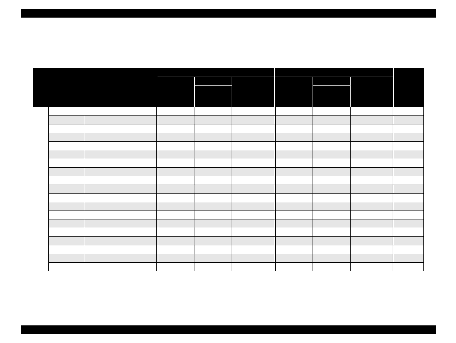
Revision Status
Revision Issued Date Description
0 January 26, 1999 Preliminary version
Page 8

Contents
Product Description
OVERVIEW ................................................................................................. 12
BASIC SPECIFICATIONS .......................................................................... 13
CONTROLLER SPECIFICATIONS ........................................................ 13
Configuration ................ ....................................................................... ... 14
ENGINE SPECIFICATIONS ................................................................... 15
PAPER SPECIFICATIONS .................................................................... 17
Process Specifications ........................................................................... 20
Paper Specifications ............................................................................... 20
RELIABILITY, DURABILITY, AND MAINTAINABILITY .......................... 22
ENVIRONMENTAL CONDITION FOR STORAGE AND
TRANSPORTATION (Including Consumables) ..................................... 24
Electrical Specifications .......................................................................... 25
SAFETY APPROVAL ............................................................................. 26
CONSUMABLES ................ .............................................. ...................... 27
External Interface Specifications ............................................................. 28
Host Interface Usage Configurations ..................................................... 28
Parallel Interface ................ ....... ...... .............................................. ......... 29
Serial Interface ....................................................................................... 29
Ethernet I/F ............................................................................................. 30
Type-B I/F ............................................................................................... 31
Panel Operation ......................................................................................... 32
Control Panel. ......................................................................................... 32
Panel Settings ........................................................................................ 34
Setting Items ...................................................................................... 34
User Setting Items which are not include in the Setting Menu ........... 38
Setting Item Description ..................................................................... 38
One-Touch Setting ....................................... ....... ...... ....... ...... ....... ...... ... 41
Special Functions ................................................................................... 41
Maintenance Mode ................................................................................. 43
Engine Status Sheet ........................................................................... 44
List of Data Controlled by the Engine Status Sheet
and Controlling Method...................................................................... 47
Dimensions and Weight ............................................................................ 48
Operating Principles
Printer Mechanism Operating Principles ................................................ 51
General Description of Each Section ..................................................... 52
Gear/Roller Location .............................................................................. 53
Electrical Component Layout ................................................................. 54
Switches and Sensors ........................................................................ 55
Paper Feeding Section ........................................................................... 56
MP Tray .............................................................................................. 56
Cassette 1 .......................................................................................... 60
Paper Feed ......................................................................................... 65
Printhead Unit (Exposure Section) ......................................................... 66
Print Process Sequence ..................................................................... 67
Imaging Cartridge ................................................................................... 68
Part Names and Functions of the Imaging Cartridge ......................... 68
Charging Section ................................................................................ 69
Development Section ......................................................................... 69
Transfer Section ................................................................................. 71
Fusing Section .................................................................................... 72
Paper Exit Section .............................................................................. 74
Detection whether New or Used Imaging Cartridge ............................... 75
Right Door Interlock Switch .................................................................... 75
Electrical Circuit Operating Principles. ................................................... 76
System Layout ....................................................................................... 76
Drive Section ...................................................................................... 76
Electrical Section ................................................................................ 77
Main Circuit (Video Controller) ... ....... ...... ....... ...... ....... ...... ..................... 78
Main Component in the Main Circuit Board ........................................ 78
Page 9

Troubleshooting
Overview ..................................................................................................... 80
Printer Messages ................................................................................... 80
Message List ...................................................................................... 80
Message Descriptions ........................................................................ 82
Service-call Error .................................................................................... 83
Engine Related Error .......................................................................... 83
Controller Related Error List ............................................................... 84
Clearing the Service-call Error ............................................................ 85
Adding on RAM ...................................................................................... 85
Troubleshooting .................. ............. ............. ............. ............. ............. ... 85
The Printer will not Start ..................................................................... 85
The Printer will no Print. ..................................................................... 86
Image Quality Problems ..................................................................... 86
Disassembly/Assembly
Overview ..................................................................................................... 88
Precaution .............................................................................................. 88
Tools ............................. ............. ............. ............. ............. ............. ......... 88
Small Parts ............................................................................................. 89
Disassembly Procedure ............................................................................ 91
ROM DIMM Removal ............................................................................. 92
Paper Eject Sensor Removal ................................................................. 93
1st Cassette Paper Take-up Roller Removal ......................................... 94
Transfer Section ..................................................................................... 95
Transfer Roller Removal .................................................................... 95
Transfer Unit Removal ....................................................................... 96
Timing Roller Front Sensor Removal ................................................. 96
Timing Clutch Removal ...................................................................... 97
Timing Roller Removal ....................................................................... 98
Internal Cooling Fan Removal ............................................................ 99
Separating the Printer ............................................................................ 99
Rear Cover Removal ............................................................................ 100
Transport Motor Removal ..................................................................... 100
I/C Drive Motor Removal ...................................................................... 101
1st Cassette Size Sensor Removal ...................................................... 101
Paper Size Sensor Removal ................................................................ 102
Top Cover Removal ............................................................................. 102
Toner Empty Sensor Removal ............................................................. 103
Main Circuit Board Removal ................................................................ 104
Engine Controller Board Removal ........................................................ 105
Power Supply Unit Cooling Fan Removal ............................................ 107
High Voltage Unit Removal .................................................................. 108
Front Cover Removal ........................................................................... 109
Control Panel Removal ........................................................................ 109
Printhead Unit Removal ....................................................................... 110
Power Supply Unit Removal ................................................................ 112
Fusing Section ..................................................................................... 113
Fuser Unit Removal .......................................................................... 113
Heater Lamp Replacement ............................................................. 114
Fusing Roller Thermistor / Thermostat / Temperature Fuse Removal 115
Upper Paper Separator Finger Removal ......................................... 118
Lower Paper Separator Finger Removal .......................................... 119
Upper Paper Eject Roller Removal ................................................. 119
Lower Paper Eject Roller Removal .................................................. 120
Drive Unit Removal .............................................................................. 121
1st Cassette Paper Take-up Solenoid (SL1) Removal .................... 123
1st Cassette Set Sensor Removal ................................................... 123
1st Cassette Paper Empty Sensor Removal .................................... 123
1st Cassette Paper Near Empty Sensor Removal ........................... 124
2nd Cassette Disassembly ................................................................... 125
Paper Take-up Roller Removal ........................................................ 125
2nd Cassette Paper Empty Sensor Removal ................................... 126
2nd Cassette Paper Near Empty Sensor Removal .......................... 126
Paper Size (Paper Size Switch) Sensor Removal ............................ 127
2nd Cassette Control Board (PWB-A) Removal ............................... 127
2nd Cassette Paper Take-up Solenoid Removal ............................. 128
2nd Cassette Right Door Set Sensor Removal ................................ 129
Updating the Firmware ......................................................................... 130
Updating the Program ROM ................................................................. 130
Error Indications and Measures ....................................................... 130
Copying the DIMM Module ................................................................... 132
Adjustment
Maintenance
Page 10

Overview ................................................................................................... 136
Maintenance by Users .......................................................................... 136
Replacement of Consumable Items ..................................................... 136
Maintenance by Servicers .................................................................... 137
Appendix
Connector Summary ............................................................................... 139
Component Layout .................................................................................. 141
Exploded Diagrams ................................................................................. 142
Housing ................................................................................................ 142
Frames ................................................................................................. 144
Fussing Section (A) .............................................................................. 146
Fusing Section (B) ................................................................................ 148
Transport Section (A) ........................................................................... 150
Transport Section (B) ........................................................................... 152
Electrical Components ......................................................................... 154
Paper Take-up Section ......................................................................... 156
Drive Section ........................................................................................ 158
Paper Tray Unit .................................................................................... 160
Circuit Diagrams ...................................................................................... 162
Page 11

PRODUCT DESCRIPTION
Page 12

EPL-N2700 Revision A
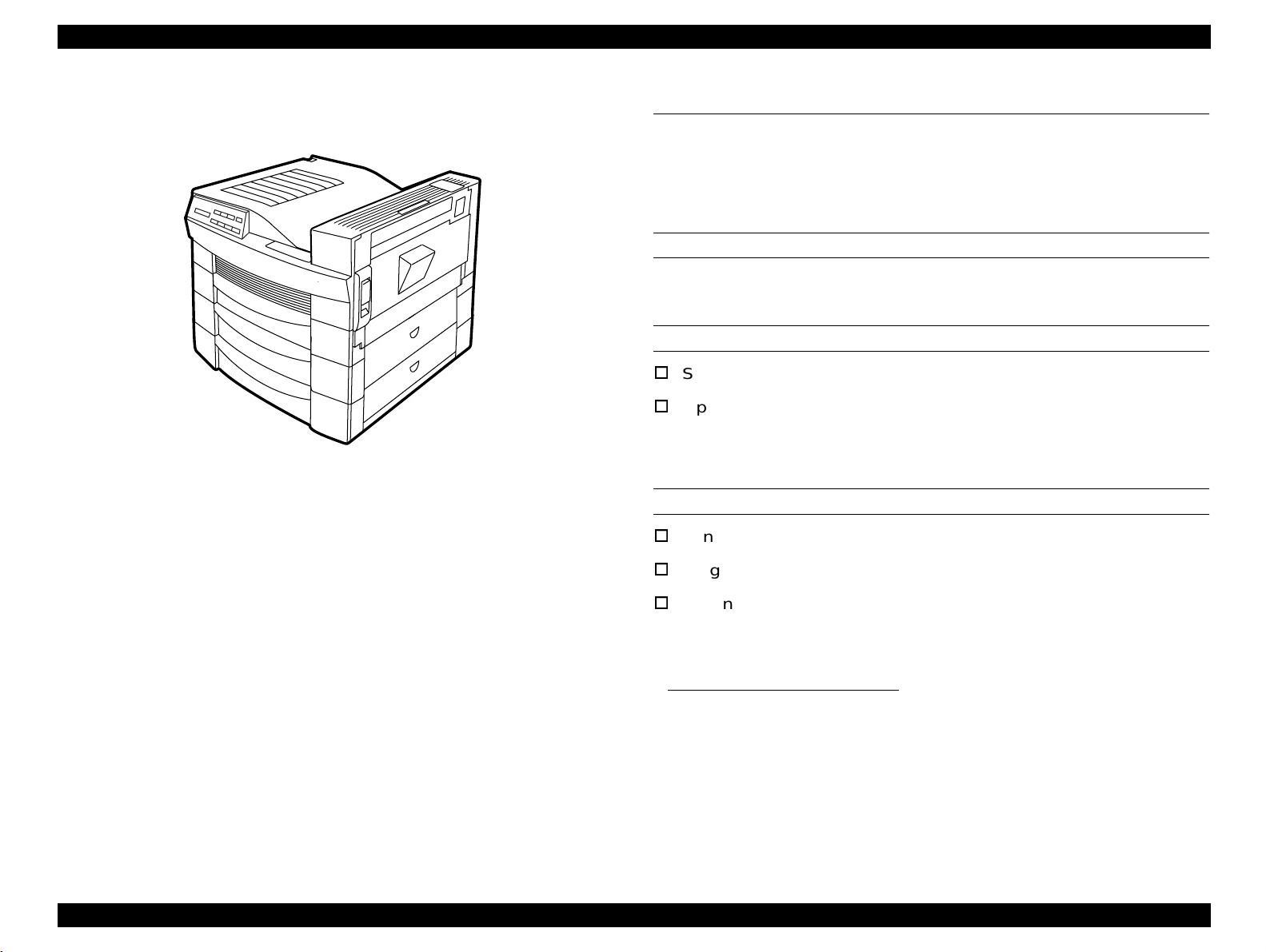
1.1 Overview
The EPL-N2700 is a business-oriented page printer making the most
use of the laser diode and the electrical photo technology. The main
feature of the printer are as follows:
ENGINE FEATURES
High-speed, highly reliable A3 Engine (Maximum duty cyc le is
100,000 sheets per month).
Resolution is 600 dpi, with a printing speed of 27 ppm when feeding
A4 from Cassette 1. (26 ppm for Letter)
Standard paper capacity is 750 sheets, 250 in the MP tray and 500
in the Cassette 1.
Holds optional cassettes to increased paper loading capacity:
One Lower Cassette (500 sheets) + Large Capacity Paper
Cassette (2500 sheets for A4 of Letter)
Up to three Lower Cassettes
SOFTWARE
IEEE l284 based parallel interface (supports ECP)
RS-232C serial interface
Ethernet Interface (100/10Base-TX)
One slot for Type B interface card
Supports Enhanced MicroGray
Supported Emulation
ESC/Page
PCL5e
ESC/P2
FX
1239X
EPSON GL2
PostScript 3 (Optional item provided on a ROM DIMM board)
Rewriting the Flash DIMM
Flash ROM in Slot A and program slot can be rewritten.
*1
Wide variety of options
Duplex unit
5-bin Multibin unit
10-bin Multibin unit.
CONTROLLER FEATURES
A new CPU (166MHz, VR4310) used for a high-speed controller
Use of SDRAM DIMM for an optional RAM will expand the standard
16-MB memory up to 256 MB.
Three types of standard interface
*1. Uninteded for users
Product Description Overview 12
Page 13
EPL-N2700 Revision A
1.2 Basic Specifications
This section describes the basic specifications of the EPL-N2700.
1.2.1 Controller Specifications
CPU
VR4310 / 166MHz
RAM
Figure 1-1. Exterior View of the EPL-N2700
Standard 16MB (on-board)
Optional 8MB*2/16MB*2/32MB/64MB/128MB/
*3
256MB
(SDRAM type,1 slot)
*1
Can be expanded up to 256MB.
ROM
Font: 2Mbytes (on-board)
Program: 4Mbytes (on Flash ROM-DIMM board)
Expansion ROM: 3 ROM-DIMM slots (Can be removed/
installed at power on only)
Available for NLSP FONT DIMM and
PostScript 3 DIMM
*1. 8MB (TBD) is alloca ted for the pr ogram area. The RAM Check at
startup shows the attached memory size, while th e status sheet
shows the size with the program code size deducted as well as the
attached memory.
*2. Not mentioned in any catalog nor specifications, since they are
hardly distributed.
*3. Availability of 25 6MB RAM , which ma y be dis tribu ted in futu re, will
be determined after the printer is in market.
Product Description Basic Specifications 13
Page 14
EPL-N2700 Revision A
INTERFACES
Standard interface:
Parallel interface:
Bidirectional parallel I/F (B type connector)
(IEEE-1284 compliant / Compatibility, Nibble and ECP mode)
Serial interface:
RS-232C
Ethernet 100/10BaseTX
Optional interface: Type-B interface slot (1 slot)
CONTROL PANEL
Consists of the 8 push-button switches, 6 LED lamps, and 20-digi t LCD
INSTALLATION FORMAT
Direct attachment
1.2.2 Configuration
The following configuration set on the controller varies according to the
destination. (See Table 1-1.) Settings are made in factory using the
jumper resistance.
Table 1-1. Configuration Classification
Version (Destination)
South American Letter
European, Pacific,
South American, Korean
North European A4
Taiwanese A4
Default for
Paper Size
A4
NLSP (Slot C)
Unsupported Unsupported
Unsupported Unsupported
Supported Unsupported
Unsupported Unsupported
Chinese
character fonts
(Slot C)
OTHER FEATURE
Does not support mechanism controller.
Product Description Basic Specifications 14
Page 15
EPL-N2700 Revision A
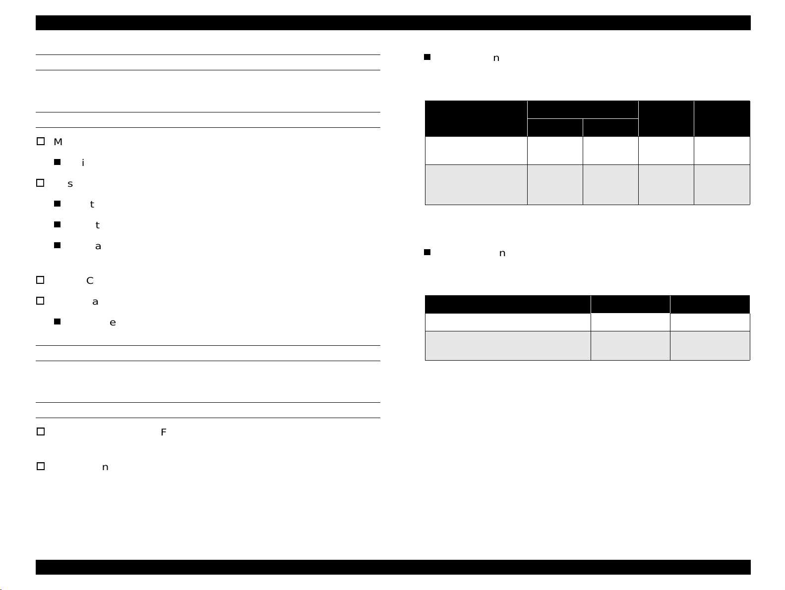
1.2.3 Engine Specifications
PRINTING METHOD
Semiconductor laser beam scan + dry-powdered single-component
magnetic toner electro-photographic printing
RESOLUTION
600DPI
PRINTING SPEED
Table 1-2. Printing Speed (Sheet / Minute)
Paper Size
A4 (SEF)* 26.0 27.0 16.9 17.0
A3 (LEF)** 14.1 14.2 8.5 8.5
A5 (SEF) 33.0
LTR (SEF) 25.4 26.0 16.7 16.7
SEF: Short Edge First, LEF: Long Edge First
NOTE:
For non-standard size paper, the printer pr ints at a lower
MP Cassette Cassette 1 MP Cassette Cassette 1
speed since the printer automatically performs cleaning.
Single Print Duplex Print
−
19.7
−
FIRST PRINT
Table 1-3. First Print
Paper Size
MP Cassette Casse tte 1 MP Cassette Cassette 1
A4 (LEF*) 11.2 11.2 20.1 20.1
A3 (SEF**) 13.3 13.3 22.4 22.4
A5 (LEF) 10.9
LTR (LEF) 11.3 11.3 20.3 20.3
*SEF: Short Edge First, **LEF: Long Edge First
Single Print Duplex Print
−
17.7
WARM-UP TIME
60 seconds or less (at 23
°C / at rated voltage
)
PAPER SOURCES
Standard
MP (Multi Purpose) cassette
Cassette 1 (Universal Paper Cassette)
Optional
Lower Cassette Unit (Universal Cassette)
−
Large Capacity Lower Cassette
NOTE:
Up to 3 optional Paper Cassette Units can be installed.
Product Description Basic Specifications 15
Page 16

EPL-N2700 Revision A
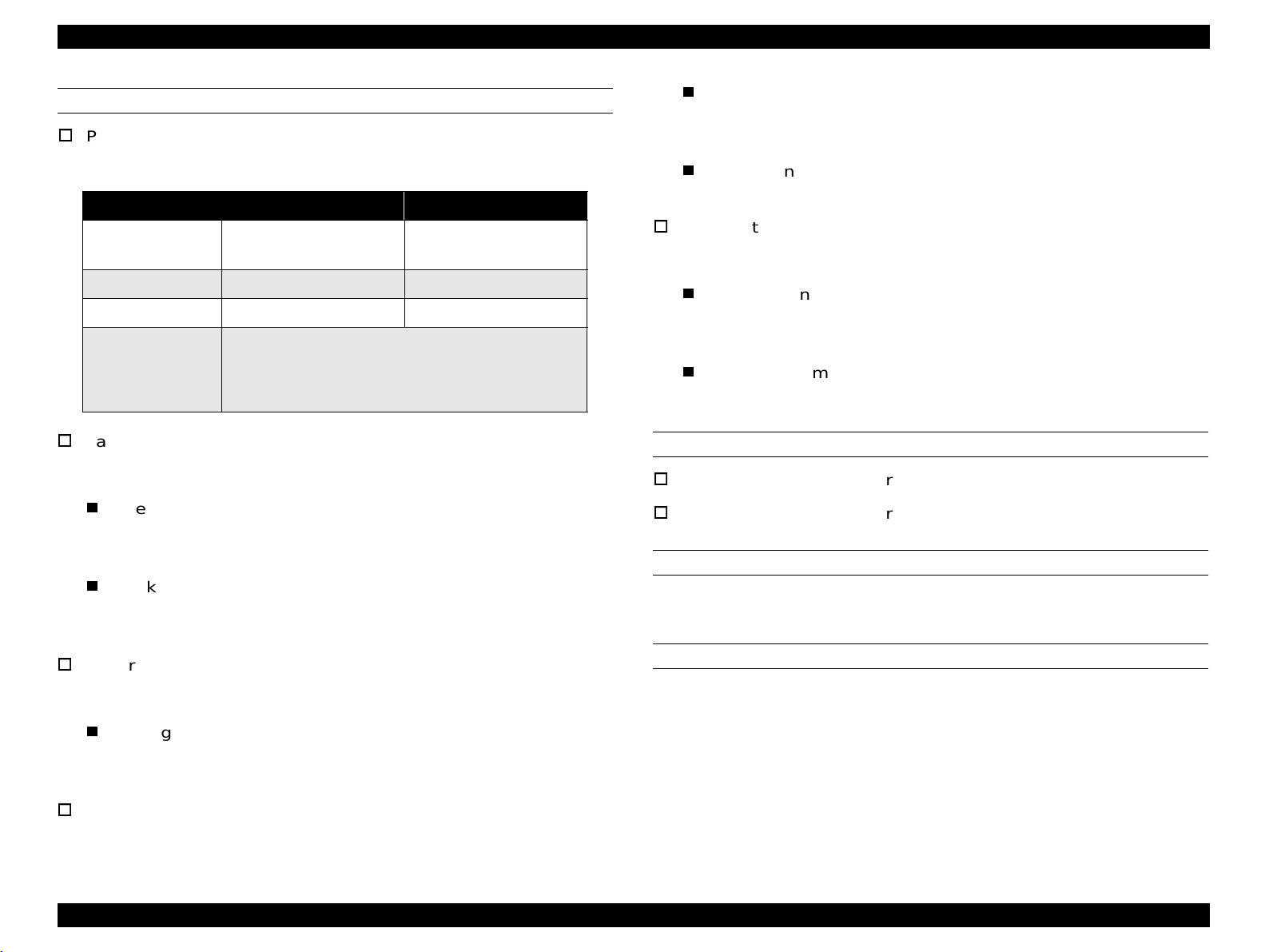
See Table 1-4 for paper source specifications.
Table 1-4. Paper Supply / Paper Size / Capacity
Paper Source / Capacity Paper Size Available Paper Thickness Available
250 sheets
MP Tray
Standard
Cassette 1 500 sheets
20 sheets
• Standard size paper within the size of:
A5(LEF
Half Letter - Ledger(SEF)
(8.5" x 5.5") (11" x 17")
• Custom size paper
Any size of paper within the range of:
Width: 86 - 297 mm
Length: 140 - 432 mm
Envelopes (Monarch, C10, DL, C5, C6)
Labels, OHP sheet, Thick paper,
Letterhead
A3(SEF), A4(LEF),
Ledger (SEF) (11" x 17")
Legal (SEF) (14" x 805")
Letter (LEF) (11" x 8.5")
G.Letter (LEF) (10.5" x 8")
*1
) - A3(LEF*2)
Normal paper:60 - 90g/m² (16 - 24lb)
• Special paper (Labels, OHP sheet)
• Normal paper: 60 - 90g/m² (16 - 24lb)
• Thick paper: 90 - 163 g/m²
Normal paper: 60 - 90g/m² (16 - 24lb)
A3(SEF), A4(LEF),
Lower Cassette
(500-sheet cassette
*3
)
unit
Option
Large Capacity
Lower Cassette
500 sheets
2500 sheets
Ledger (SEF) (11" x 17")
Legal (SEF) (14" x 805")
Letter (LEF) (11" x 8.5")
G.Letter (LEF) (10.5" x 8")
A4 (LEF)
*4
Letter (LEF) (11" x 8.5")
Normal paper: 60 - 90g/m² (16 - 24lb)
Normal paper: 60 - 90g/m² (16 - 24lb)
*1: Set paper with the Long Edge First.
*2: Set paper with the Short Edge First
*3: Up to 3 optional Lower Cassette Units can be installed.
*4: With 80g/m² paper
Number of sheets loaded
Standard: 750 sheets (250 + 500)
With options: Up to 3,750 sheets in total. (Standard: 250 + 500, Optional 500 + 2,500)
Product Description Basic Specifications 16
Page 17
EPL-N2700 Revision A
1.2.4 Paper Specifications
See Table 1-5 for the paper sources and their paper availability.
Table 1-5. Paper Sources and their Paper Availability
North America Europe
Type
A3 297 x 420 AC AM AA AM AC
A4 (LEF) 210 x 297 AC AM AA AM AA AC
A5 (LEF) 148 x 210 AC AA AC
JIS-B5 (LEF) 182 x 257 AC AC AC
ISO-B5 (LEF) AC AA AC
LTR (LEF) 215.9 x 279.4 (8.5 x 11") AA AM AA AA AM AA AC
HLT (LEF) 139.7 x 215.9 (5.5 x 8.5") AA AC AC
LGL 215.9 x 355.6 (8.5 x 14") AA AM AA AM AC
EXE (LEF) 184.15 x 266.7 (7.25 x 10.5") AA AC AC
Normal Paper
GLG 215.9 x 330.2 (8.5 x 13") AA AC AC
GLT (LEF) 203.2 x 266.7 (8 x 10.5") AA AM AC AM AC
B AA AM AC AM AC
F4 210 x 360 AC AA AC
Nonstandard 330 x 275 AC AC
MON 98.43 x 190.5 (37/8 x 7½") AC AC
C10 104.78 x 241.3 (41/8 x 9½") AC AC
DL 110 x 220 AC AC
C5 162 x 229 AC AC
special paper
C6 114 x 162 AC AC
Size
mm (inch)
MP Cassette
Cassette 1
500 -Sheet
Lower
cassette
Large Capacity
Lower Cassette
MP Cassette
Cassette 1
500-Sheet
Lower
cassette
Large Capacity
Lower Cassette
Duplex
Unit
NOTE:
AA: Available (Automatic paper size detection is supported for MP cassette.)
AM: Available (Manual paper size detection is supported. Paper size is set with dials.)
AC: Available (Paper size is set though the control panel.)
Product Description Basic Specifications 17
Page 18
EPL-N2700 Revision A
CONSUMABLES AND OPTIONS
Imaging Cartridge
With a 5-bin Unit installed:
Table 1-6. Paper Ejection Capacity with 5-bin Unit
SUPPORTED PAPER SIZES
MP Cassette:
Width =86 to 297 mm (3.39 to 11.7 ")
Cassette 1:
Width = 215.9 to 297 mm (3.9 to 11.7 ")
Length = 203.2 mm to 431.8 mm (8 to 17 ")
Available paper size = A3 (SEF), A4 (LEF),
Letter (SEF), Letter (LEF), G.Letter (LEF)
Lower Cassette: Same as for the Cassette 1.
Large Capacity Lower Cassette:
Available paper size = A4(LEF), Letter(LEF)
PAPER FEED ALIGNMENT
Center alignment for all paper sizes
Paper Type
Normal paper
(60 - 90 g / m
Envelopes, OHP sheets
Thick paper
(90 - 163 g / m2)
NOTE:
With a 10-bin unit installed:
2
)
Each bin is equipped with the full stack sensor.
Table 1-7. Paper Ejection Capacity with 10-bin Unit
Normal paper (60 - 90 g / m
Envelopes, OHP sheets
Thick paper (90 - 163 g / m
NOTE:
Each bin is equipped with the full stack sensor.
Bin 1
Normal Shifting
250 sheets 250 sheets 50 sheets 100 sheets
10 sheets
(TBD)
2
) 200 sheets 200 sheets
2
)
− − −
10 sheets
(TBD)
Bin 2 - 4 Bin 5
Bin 1 Bin 2 - 20
−
PAPER EJECTION
Standard: Face-down ejection only
2
g / m
)
With options:
Holds up to 500 sheets (75
See Table 1-6 and Table 1-7 for paper ejection capacity with the
optional 5-bin/10-bin Unit installed.
Product Description Basic Specifications 18
Page 19
EPL-N2700 Revision A
POWER CONSUMPTION
Average consumption current:
1.3 A or less (24V)
Printer Main Body: See Table 1-8.
Table 1-8. Power Supply Specification
Item 100V Model 200V Model
Input Voltage
Rated Frequency 50 - 60Hz ±3Hz 50 - 60Hz ±3Hz
Rated Current 11.5 A 6.0 A
• Maximum: 1050W
Power
Consumption
Large Capacity Paper Cassette Unit
• Continuous printing: 750W
• Stand-by (H eater ON): 200W
• Stand-by (Heater OFF): 45W
120V ±10%
(90 to 132V)
220 - 240V ±10%
(198 to 264V)
NOISE:
0.5 A or less (5V)
Power consumption:
32 W or less (TBD)
5-bin Unit
DC24 V and DC5 V are supplied from the printer.
Average consumption current:
1.0 A or less (24V)
0.3 A or less (5V)
Power consumption:
24 W or less (TBD)
DC24 V and DC5 V are supplied from the printer.
Average consumption current:
Stand-by: Approximately 38.0 dB (A) or less
Operating: Approximately 55.0 dB (A) or less
1.0 A or less (24V)
0.5 A or less (5V)
Peak current:
1.5 A or less (24V)
OZONE DENSITY
0.1 ppm or less
0.5 A or less (5V)
Lower Cassette Unit:
DC24 V and DC5 V are supplied from the printer.
Average consumption:
TOXICITY
OPC, toner, and plastic materials are all nontoxic.
TBD (24V)
TBD (5V)
10-bin Unit:
DC24 V and DC5 V are supplied from the printer.
Product Description Basic Specifications 19
Page 20
EPL-N2700 Revision A
1.2.5 Process Specifications
Printing system: Dry single-component toner
electrophotographic process
Carbon paper, "non-carbon" paper
Thermal paper, pressure-sensitive paper, Acidic paper
Paper already printed on by thermal-transfer printer or ink jet
printer
Exposing source: Semi-conductor laser beam
Exposed object: OPC drum
Charging system: Rotating charging brush system
Developing system: Exposed area developing system
Thin or thick paper (exceeding the specificati on)
Wet (damp) paper
Paper with coated or processed color surface
Paper with extra smooth or extra rough surface
Paper whose smoothness on the both sides are largely different
Toner: Single-component nonmagnetic toner
Transfer system: Roller transfer system
Fixing system: Heat roller system
Paper with perforation or binder holes
Folded, curled, or torn paper
Paper of irregular shape
Paper cut at off-angle
Density control: Variable developer bias (can be set by yser)
Label sheets that peel too easily
Paper with clips, staples, glue, and so on.
1.2.6 Paper Specifications
Paper exclusively designed for ink jet print ers (s uper fine paper ,
PAPER TYPE
Standard paper: Xerox 4024 DP paper 20lb (75 g/m
Normal paper: 60 g/m
2
- 90 g/m2 (16 lbs - 24 lbs)
Copy paper, bond paper, and recycled paper
that are generally used
2
)
glossy paper, glossy film, and so on.)
Transparency film designed for color photo copier or color laser
page printer.
Paper already printed on with a color/monochro me laser printer
or photo copier.
Paper pasted together
Special paper: Labels, OHP film, Color paper, Thick paper
2
(90 - 157 g/m
), DTP paper, and Letterhead
CAUTION
Use of illustrated postcard may leave paper debris on
the paper loading roller, which causes the printer to
NOTE:
Do not use the following papers in this pri n ter. Use of any of
the following papers will causes the printer malfunctions
such as print problem and paper jam, and also damage the
feed paper improperly. If this problem occurs, clean
the paper loading roller. (Refer to Chapter 6
“Maintenance” for cleaning method.)
printer.
Product Description Basic Specifications 20
Page 21

EPL-N2700 Revision A
G uaranteed
print area
4m m
4m m
4m m 4m m
PAPER PATH AVAILABILITY
Table 1-9. Paper Path Availability
Special Paper
Standard
paper
MP Cassette RF R PPPPP
Cassette 1 RF R N N N N N
500-sheet lower
cassette unit
Large Capacity
Lower Cassette
Duplex Unit RF R NNNNN
RF: Reliable feeding and good image quality.
R: Reliable feeding and good image quality, but limited to paper generally available.
P: Possible, but limited to paper generally available.
N: Not supported
RF R NNNNN
RF R N N N N N
Normal
paper
OHP sheet
Postcard
Label
Thick paper
Envelope
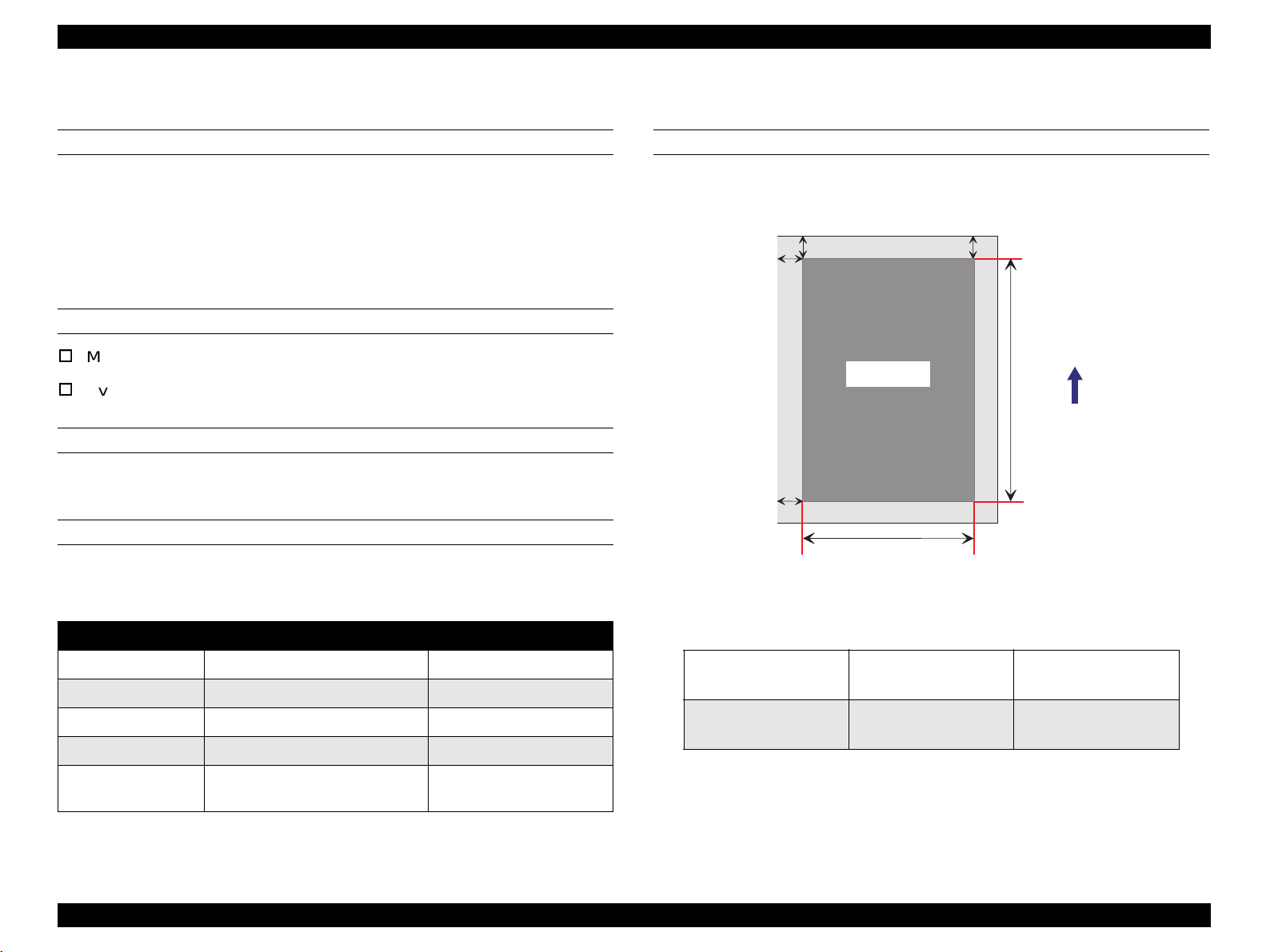
PRINTABLE AREA
Printable area: TBD
Guaranteed print area:Area other than 4 mm inward from each
edge. (See Figure 1-2.)
NOTE:
Guaranteed printable area may vary depending on the
printer mode.
Figure 1-2. Guaranteed Printable Area
Product Description Basic Specifications 21
Page 22
EPL-N2700 Revision A
a
b
c
d
e
f
Print area
Paper feeding direction
1.2.7 Reliability, Durability, And Maintainability
MPBF
60,000 sheets (For single-side print)
NOTE:
MPBF is an average number of sheets printed between
failures, where "failure" indicates a condition that requires
part replacement or that cannot be corrected by user.
PRINT VOLUME
Maximum = 100,000 sheets / month
Average = 10,000 sheets / month
MTBF
3,000 H (10 months) or more
PAPER FEED RELIABILITY
When standard paper is used in the standard environment:
Table 1-10. Paper Feed Reliability
PRINT POSITION ACCURACY
Jam rate
Feed failure 1/2000 or less TBD
Multiple paper feeds 1/500 or less TBD
Paper wrinkle 1/1000 or less 1/500 or less
*1
Edge bent
*1: Multiple feed is not included.
*2: 1C means 1 corner bent by 1 mm or less.
Single-side Print Duplex print
1/2000 or less 1/1000 or less
1/1000 or less for 1C or more
(Less than 1C is disregarded.)
1/500 or less
*2
Single-side print
Duplex print
Table 1-11. Print Position Accuracy
Main scan direction (c)
Sub scan direction (a)
Main scan direction (c)
Sub scan direction (a)
±2.mm
TBD
±3.mm
TBD
Product Description Basic Specifications 22
Page 23

EPL-N2700 Revision A
SKEW
Ambient Illumination: 3000 lux or less
(Must avoid direct sunlight.)
Table 1-12. Paper Skew
Space Requirement:
Print mode Direction A4 (LEF) A3 (SEF)
Single-side
print
Duplex print
Main scan direction (c
Sub scan direction (a
Main scan direction (c − d)
Sub scan direction (a − b)
d)
−
b)
−
±2.mm TBD
±1.5.mm TBD
±3.mm TBD
±2.5.mm TBD
DURABILITY
5 years or 600,000 sheet, whichever comes first.
MAINTAINABILITY
MTTR* = Within 30 minutes (average)
*
MTTR: Mean Time To Repair
EJECTION CURL
Normal paper:
OHP Sheet:
± 15 mm or less (TBD)
± 10 mm or less (TBD)
To ensure proper operation of the printer, sufficient open space
must be left around printer, as indicated in Figure 1-3.
TBD
TBD
< Top View >
734 m m (W ith the R ight C over open)
950 m m
OPERATING CONDITIONS (INCLUDING CONSUMABLES)
Temperature: 10 to 35°C
Humidity: 15 to 85%RH (without condensation)
Air Pressure (Altitude):760hPa or more (below 2500m)
Tilt: 1° or less (rear
↔ back, right ↔ left)
(W ith the C assette extended to the m axim um )
Figure 1-3. Space Requirement
Product Description Basic Specifications 23
Page 24

EPL-N2700 Revision A
1.2.8 Environmental Condition For Storage And Transportation (Including Consumable Items)
TEMPERATURE AND HUMIDITY
Table 1-13. Environmental Conditions - Main Unit
Item Conditions
Normal 0 to 35°C
Extreme
(1/30 of the total st orage
period)
Temperature
Normal 30 to 80%RH
Extreme
(1/30 of the total st orage
Humidity
period)
Storage duration Within 18 months from the production
*1: 35 - 55 °C without an ET Cartridge
High temperature 35 to 40°C *1
Low temperature -20 to 0°C
High humidity 85 to 95%RH
Low humidity 10 to 30%RH
AIR PRESSURE
74.0 to 101.3 kPa (Max. 555 - 760 mm Hg)
VIBRATION TOLERANCE
Vibration: 5 to 100Hz / 100 to 5Hz
Acceleration: 1G
Sweep time: 10 minutes (one way)
Direction: Three directions (X/Y/Z)
Time: 60 minutes in each direction
DROP TOLERANCE
No damage when tested in accordance with JIS Z0200-1987 level 1
Direction: 1 corner, 6 sides, 3 edges
Product Description Basic Specifications 24
Page 25
EPL-N2700 Revision A
1.2.9 Electrical Specifications
AC LINE NOISE
Pulse width: 50 to 1000 ns
Pulse polarity: + / -
Repetition: Asynchronous
Modes: Common / Normal
Voltage: 1KV
(Parts must be able to withstand 2KV without
damage)
TRANSIENT OUTAGE
DIP 100% (at rated voltage - 10%) 1 cycle
(No abnormal print quality)
ELECTROSTATIC TOLERANCE
Up to 10KV: No hard error, no user-nonrecoverable
software error
DIELECTRIC STRENGTH
Insulation shall not break down when the following voltage is applied
between primary circuit and chassis for 1 minute:
100V version: AC1000V
200V version: AC1500V
LEAKAGE CURRENT
3.5mA or less
Up to 15KV: No damage to parts
SURGE CURRENT
1/2-cycle / Not above 50A
INSULATION RESISTANCE
Ω or more
10M
Product Description Basic Specifications 25
Page 26
EPL-N2700 Revision A
1.2.10 Safety Approval
SAFETY REGULATION
Table 1-14. Safety Regulation
Model Applicable Standard
100V version
200V version
SAFETY REGULATION (LASER RADIATION)
Table 1-15. Safety Regulation (Laser Radiation)
Model Applicable Standard
100V version FDA (NCDRH) Class 1
200V version TUV-GS (EN60825)
• UL 1950
• CSA 22.2 No.950
• TUV-GS (EN60950)
•CCIB
• Complies with a safety regulation of the following countries:
Russia, Singapore, Hong Kong (IEC950), Korea
POWER CONSUMPTION
In compliance with International Energy Star program
OTHERS
Toner:
No effect on human health.
(In compliance with OSHA, TSCA, EINECS, worker saf ety laws an d
CSCL)
OPC:
No effect on human health. (In compliance with OSHA)
Ozone:
In compliance with UL478 5th Edition
Materials:
In compliance with Swiss environment protecti on law (no CdS
content)
EMC
Table 1-16. Safety Regulation (EMC)
Model Applicable Standard
100V version
200V version
• CNS 13438 (for Taiwan)
• FCC Part15 Subpart B Class B / CSA C108.8 Class B
• EC EMC directive 89/336/EEC
• EN55022 Class B
• EN61000-3-2
• EN61000-3-3
• EN50082-1
• AS/NZS 3548 class B (for Australia)
• Korea EMC class B
Product Description Basic Specifications 26
Page 27

EPL-N2700 Revision A
1.2.11 Consumable Item
This printer's only consumable part is the Imaging Cartridge.
SPECIFICATIONS
Table 1-17. Imaging Cartridge Specifications
Name Components Life Weight
•OPC Drum
• Charging unit
ET Cartridge
*1: Toner life is estim ated based on continu ous pri nting on A 4 (LEF) size paper
with 5% print co verage. Toner life will vary accordin g to print coverage and
printing method (continuous or intermittent, print density, and toner-save
mode).
*2: If the number of photo conductor rotation reaches the values equivalent to
25,000 sheets (A4 LEF / continuous) before toner life-end is detected, the
printer detects t he c ond iti on as t one r empty, same as the c ond iti on "ET Toner
Cartridge has expired its life".
• Development unit
• Single-component
unmagnetic black
toner
Average:
15,000 pages
Approximately 2.5
*1 *2
Kg
ENVIRONMENTAL CONDITION FOR STORAGE AND
TRANSPORTATION
Table 1-18. Environmental Conditions - Consumables
Item Conditions
Normal 0 to 35°C
Extreme
(1/30 of the total
storage period)
Temperature
Normal 30 to 85%RH
Extreme
(1/30 of the total
Humidity
storage period)
Air Pressure: 74.0 - 101.3 KPa (555 to 760mmHg)
Storage duration Within 18 months from the production
High temperature 35 to 40°C
Low temperature -20 to 0°C
High humidity 85 to 95%RH
Low humidity 10 to 30%RH
(unpacked)
DROP TEST
Same as for the printer main body.
VIBRATION
Same as for the printer main body.
Product Description Basic Specifications 27
Page 28

EPL-N2700 Revision A
)
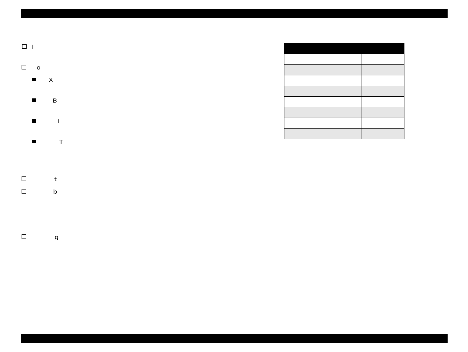
1.3 External Interface Specifications
The EPL-N2700 supports the following interfaces .
Bidirectional parallel I/F (standard)
RS-232C serial (standard)
Ethernet I/F
Type-B interface slot (option)
See Figure 1-4 for the locations of the Interface slots.
Ethernet I/F C onnector
(1 )
(2 )
O ptional TypeB S lot
Parallel I/F C onnector
(IE E E 1284 B C onnector
1.3.1 Host Interface Usage Configurations
The EPL-N2700 has the automatic interface switching mode. however,
the interface to be used can be fixed by a control panel operation.
Table 1-19. Host Interface Usage Configurations
Parallel I/F Serial I/F Ethernet I/F Type B I/F
1. Automatic I/F
switching
2. Fixed I/F
(Parallel)
3. Fixed I/F
(Serial)
4. Fixed I/F
(Ethernet)
5. Fixed I/F
(Type B I/F))
Usable Usable Usable Usable
Usable Not Usable Not Usable Not Usable
Not Usable Usable Not Usable Not Usable
Not Usable Not Usable Usable Usable
Not Usable Not Usable Not Usable Usable
S e ria l I/F C o n n e c to r
(1) 100Base/10B ase Lam p (C olor: O range)
(2) Link/Reception Lam p (C olor: G reen)
Figure 1-4. Interface Slot Location
Product Description External Interface Specificati ons 28
Page 29

EPL-N2700 Revision A
1.3.2 Parallel Interface
Interface type: IEEE1284 bidirectional high-speed parallel
interface
Operation modes: Compatibility, Nibble, ECP
Connector: 57RE-40360-830B(D7A) DDK or equivalent
Applicable plug: Amphenole equivalent
Device ID:
*1;
MFG:
CMD:
MDL:
CLS:
DES:
*1. Total length of Device ID + 2 (hex) are entered in hexadecimal.
*2. The following character string appears when an optional ROM DIMM is
*3. Displays model name: EPL-N2700
EPSON;
PJL, EJL, ESCPL2-00, ESCP9-84, PRPXL24-01, HP ENHANCED
PCL5, HPGL2-01, ESCPAGE-04, ESCPAGE-04
*3
PRINTER;
EPSON EPL-N2700;
installed:
- PostScript 3 DIMM: ,POSTSCRIPT (TBD)
∗∗
*2;
1.3.3 Serial Interface
Type: RS-232C
Synchronization: Asynchronous
Transmission rates: 300 to 115200 bps
Parity bit: Even, Odd or NONE
Start bit: 1
Stop bit: 1 / 2
Data length: 7 or 8 bits
Hardware protocols: DTR/DSR
Software protocol: XON/XOFF (Robust mode is supported)
Connector: 17LE-13250-27(D57) DDK or equivalent
NOTES:
Page returns have been inserted in the explanation above to
make it easier to read, but it is actually given in a serial string
format without any breaks.
The CMD parameters are shown in random order. The items
MODE and STATUS are not included.
DES has the values for the MFG and MDL which are connected
with a space in between.
Product Description External Interface Specificati ons 29
Page 30
EPL-N2700 Revision A
1.3.4 Ethernet I/F
I/F type: 10BaseT, 100Base T , Half Duplex, Full
Duplex (Switched at power on)
Communication protocol:
IPX/SPX (IPX, SPX, NCP, RIP, SAP, PrintServer,
RemotePrinter, NDS, SNMP)
NetBIOS (SMB)
NetBEUI
TCP/IP (IP, UDP, TCP, LPR, FTP, TELNET, APR, ICMP,
RARP, BOOTP, DHCP, SNMP, HTTP)
AppleTalk (ELAP, DDP, ATP, PAP, AARP, NBP, ZIP, RTMP)
(When AppleTalk is used, items such as printer name must be
set on the Web browser. EPSON Net and EPSON Net2 can not
be used.)
Connector: RJ45
Applicable cable: 2-pair category 3, 4 or 5 UTP (10BaseT,
100BaseT)
(To conforms with ECC Class B, EN55022
Class B, VCCI Class B, a shielded cable must
be used.) (T BD)
Table 1-20. Ethernet I\F Pin Assignment
Pin Signal Name I/O
1Tx+ O
2Tx- O
3Rx+ I
4N.C.
5N.C.
6 Rx- I
7N.C.
8N.C.
−
−
−
−
Pin assignment: See Table 1-20.
Product Description External Interface Specificati ons 30
Page 31

EPL-N2700 Revision A
1.3.5 Type-B I/F
This printer is equipped with one slot for an optional Type-B interface
card.
Main System Type: MTP600dpi,PW7016dt600dpi,PRG(
AP1300ma,SPD0fast
∗∗∗∗: ROM version)
(
Printer Name: Factory value is the same as the Product
Name.
Product Name: EPL-N2700
Emulation type: See Table 1-21.
Entity type: See Table 1-21.
When the emulation is set to "Auto", the following Entity Types are
returned:
If PS is supported:
EPSONPCL5, EPSONPAGE4, EPSONLQ2
(EPSONHPGL2, EPSONFX, EPSONPRPXL24)*
∗∗∗∗)rev,
Table 1-21. Emulations Available
Emulation Emulation Type Entity Type
LJ4 PCL5E-00 EPSONPCL5
GL/2 HPGL2-01 EPSONHPGL2
PS POSTSCRIPT-00 LaserWriter
FX ESCP9-84 EPSONFX
ESCP2 ESCPL2-00 EPSONLQ2
1239X PRPXL24-01 EPSONPRPXL24
ESC/Page ESCPAGE-04 EPSONPAGE4
ESCPC ESCP24C-84 EPSONLQ0C
RCC *1
*1: Can not be selected by users.
−−
If PS is unsupported:
LaserWriter, EPSONPCL5, EPSONPAGE4
(EPSONNLQ2, EPSONHPGL2, EPSONFX, EPSONPRPXL24)*
* The Entity Types in the brackets are returned when the
number of multi-entity is 3 or more.
Product Description External Interface Specificati ons 31
Page 32

EPL-N2700 Revision A
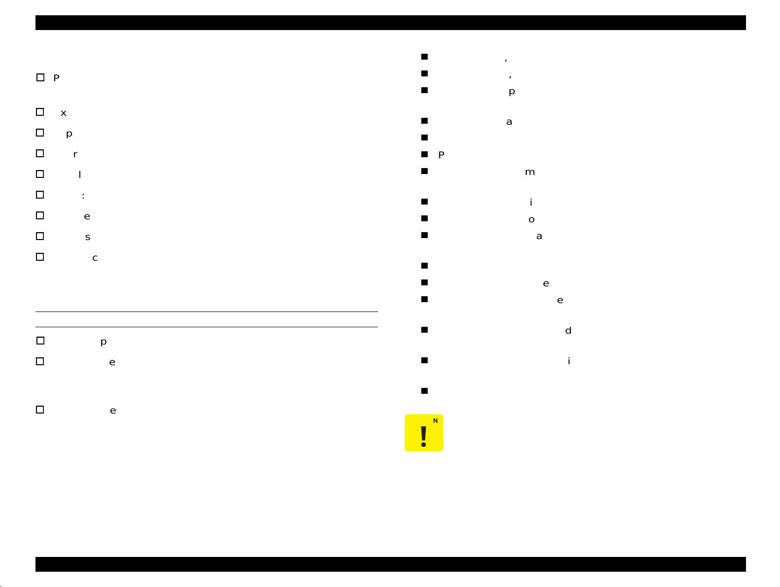
1.4 Panel Operation
Data LED (Yellow)
ON: Printer contains data that has not yet been proces sed.
The control panel of the EPL-N2700 includes a variety of buttons and
indicator lamps, together with an LCD. The user can use the panel to
select the printer's operating mode, to set the various printer functions,
and to view settings and status information.
OFF: Printer has finished processing all print data.
(If data is not effective print da ta, light will not be on.)
(If control code is not terminated, however, this lamp will
be ON.)
Blinking: Printer is currently processing data.
1.4.1 Control Panel.
Continue LED (Red)
Blinking: Printer is in an error state. User can clear the error
by pressing the Continue button.
AB C
D
E
F
G
One-Touch Mode 1 LED (Green)
Indicate that the printer is in One-Touch mode 1. This mode offers
O rientation
Toner Save
Value Enter
Mode
N
O
the direct access to the following items:
Paper Source, Paper Size, Manual Feed, Orientation
One-Touch Mode 2 LED (Green)
Indicate that panel is in One-Touch mode 2. This mode offers the
direct access to the following items:
On Line
H
Form Feed
I
Paper Source P aper S ize M anual Feed
C ontinue
JK
Reset
SelecType
ALT
RITech
Menu Item
L
MP Tray Size
C opies
M
RITech, Copies, MP Tray Size, Out Bin
Figure 1-5. EPL-N2700 - Control Panel
SelecType (Green)
Indicates that printer is in SelecType setting mode.
LCD PANEL
NOTE:
All LEDs come on when a service-call error has occurred.
1-line by 20 column LCD display equipped with backlog, and it is used
for displaying printer status and setup menus
LED INDICATORS
On Line LED (Green)
ON: Printer is ready to receive data and print.
BUTTONS
On Line button
Toggles printer ON-LINE state on and off. (If printer is in one of the
setup modes, this switch releases the mode and sets the printer to
On-Line state.)
OFF: Printer is not for receiving print data.
Product Description Panel Operation 32
Page 33

EPL-N2700 Revision A
Form Feed button
If the printer contains data but is not enabled for printing (if Form
Feed lamp is on), this switch causes print er to output printing r esults
and eject the paper. (This button does not cause ejection if Form
Feed lamp is off.)
Continue button
Clears error (if pressed while Continue LED is blinki ng). When
printer is in On-Line state, this butt on will also clear any warning
display that may appear on the LCD.
SelecType / ALT button
Selects the panel setting mode: OneTouch Mode 1, OneTouch
Mode 2, or SelecType Mode. Also operates as a ALT key. Panel
button operations vary according to the currently selected panel
setting mode.
MENU button
Selects the corresponding OneTouch mode setting l isted above t his
button, or selects the SelecType menu if in SelecType mode. Press
this button when the printer is on-line to enter SelecType mode.
setting when in SelecType mode.
Press this button twice when the printer is on-line to pri nt the Status
Sheet.
RESET (ALT + Continue)
Pressing the Continue button while h olding down the ALT b utton will
reset the printer. The LCD will display the message RESET. To
generate a complete reset (warm boot), continue t o hold down these
buttons for approximately five seconds after the RESET message
appears; the message will then change to RESET ALL and the
printer will start warm-up processing.
CAUTION
1. This printer has a non-volatile memory (EEPROM) to
store various setting values and print data. If the
printer power is turned off while it is writing data, the
ongoing writing operation is not completed and an
error may occur at the next power on. Therefore, be
sure not to turn the printer off when the printer is in
any of the following conditions because a writing
operation is processing.
ITEM button
Selects the corresponding OneTouch mo de option listed above this
button, or selects the function available within the current menu,
after entering the SelecType mode.
VALUE button
Selects the corresponding OneTouch mo de option listed above this
2. To stop printing, press the On Line button or perform
Printer is turned on but the On Line LED has not
come on yet.
On Line LED is blinking.
Printer is printing. (PF motor is live.)
Job Cancel / Reset operation.
button, or selects the parameter available within the current item,
after entering the Item of the SelecType mode.
ENTER button / Status Sheet print
Selects the corresponding OneTouch mo de option listed above this
button, or accepts the setting currently shown on the LCD as a new
Product Description Panel Operation 33
Page 34

EPL-N2700 Revision A
1.4.2 Panel Settings
Table 1-23. SelecType Option (2/7)
1.4.2.1 Setting Items
The following tables show the panel setting options available.
Table 1-22. SelecType Option (1/7)
MENU Button
ITEM Button VALUE Button
Test Menu
Status Sheet
Network Status Sheet
PS3 Status sheet
PS3 Font Sample
ESC/Page Font Sample
LJ4 FOnt Sample
FX Font Sample
1239S Font Sample
Emulation Menu
Parallel / Serial /
Network / AUX
Printing Menu
Paper Source
Page Size
Wide A4
Orientation
Out Bin
Copies
Quantity
*26
Manual Feed
Resolution
Skip Blank Page
Duplex
Binding
*10
*10
(Continued to the next table)
*1
*1
*4
Auto / LJ4 / ESCP2 / FX / I239X / PS3 *1 /
*2
GL2
Auto / MP / LC1 / LC2
*20
A4
/ A3 / A5 / B4 / B5 / LT
*3
/ LC3
*3
*19
/ B / HLT /
LGL /GLT / GLG / EXE / F4 / MON / C10 / DL
/ C5 / C6 / IB5 / CTM
OFF / ON
Port
/ Land
Face-Down / Stacker *6 / Staple *8 /
Mailbox 1
*7
− 10 *7 / Sorter
*25
1 − 999
1 − 999
OFF
/ ON
600 / 300
*9
OFF / ON
OFF
/ ON
Long Edge / Short Edge
MENU Button
ITEM Button VALUE Button
Printing Menu
(Continued from the previous table)
Start Page
Offset Stacking
Finish
Staple Position
Punch
*10
*11
*12
*12
*12
Tray Menu
MP Mode
MP Tray Size
LC1 Size
LC2 SIze - LC3 Size
*13
*3 *13
MP Type
LC1 Type
LC2 Type *3, LC3 Type
*3
Config Menu
RITech
Toner Save
Density
Top Offset
Left Offset
*10
*10
T Offset B.
L Offset B.
Size Ignore
Auto Cont
Page Protect
Image Optimum
Paper Type
Front / Back
OFF
/ ON
None / Staple
Left / Right
None / Punch
Normal / Last
Auto *5 / A4 / A3 / A5 / B4 / B5 / B / LT /
HLT / LGL / GLT / GLG / EXE / F4 / MON /
C10 / DL / C5 / C6 / IB5
A4 / A3 / B4 / LT / B / LGL / GLT
A4 / A3 / B4 / LT / B / LGL / GLT (Universal
Cassette), A4, LT, B5 (LCC)
/ Preprinted / Letterhead / Bond /
Plain
Recycle / Color / Transprncy / Labels
/ Preprinted / Recycle / Color
Plain
Plain
/ Preprinted / Recycle / Color
ON / OFF
OFF / ON
3
/ 4 / 5 / 1 / 2
-150.0 - 0.0 - 150.0 (step: 0.5mm)
-150.0 - 0.0 - 150.0 (step: 0.5mm)
-150.0 - 0.0
- 150.0 (step: 0.5mm)
-150.0 - 0.0 - 150.0 (step: 0.5mm)
OFF / ON
OFF
/ ON
Auto / ON
Auto / OFF / ON
Normal / Thick W / Thick N / Trnsprnc /
Ltrhead
Product Description Panel Operation 34
Page 35

EPL-N2700 Revision A
Table 1-24. SelecType Option (3/7)
MENU Button
ITEM Button VALUE Button
Setup Menu
Interface
Time Out
Standby
*14
Lang
Panel Lock
Toner
Multibin
Finisher
Page Count
*15
*13
*27
*12
*13
SelecType Init
Parallel Menu
Speed
Bi-D
Buffer Size
Serial Menu
Word Length
Baud Rate
Parity
Stop Bit
DTR
Xon/Xoff
Buffer Size
Network Menu
Get IPAddress
IP Byte 1 - IP Byte 4
SM Byte 1 - SM Byte 4
GW Byte 1 - GW Byte 4
Buffer Size
AUX Menu *2
Buffer Size Normal / Maximum / Minimum
Auto / Parallel / Serial / Network / AUX
0, 5 - 60 - 300 (step: 1)
Enable / Disable
English
/ Français / Deutsch / ITALIANO / ESPANOL /
SVENSKA / Dansk / Nerderl. /SUOMI / Português
OFF
/ ON
E****F
−
E
F
Mailbox / Stacker / Sorter / MultiSort
Mailbox / Stacker / Sorter / MultiSort
0 - 99999999
Fast / Normal
Nibble / ECP / OFF
Normal
/ Maximum / Minimum
8 / 7
9600 / 19200 / 38400 / 57600 / 76800 / 115200 / 300 /
600 / 1200 / 2400 / 4800
/ Even / Odd
None
1
/ 2
ON / OFF
ON / OFF / Robust
Normal / Maximum / Mi nimum
Panel / DHCP / PING
0 − 255
0
− 255
0 − 255
Normal / Maximum / Minimum
Table 1-25. SelecType Option (4/7)
MENU Button
ITEM Button VALUE Button
*22
*4
On / Off
On
/ Off
CR / CR+FF
CR+FF / LF
CR+FF
/ FF
Ignore / Space
Off / On
On
/ Off
Resident / Download / ROM A
*23
/ ROM B
*23
0 - available (max. 65535)
0.44 - 10.00
- 99.99 (step:0.1cpi)
4.00 - 12.00 - 999.75 (step:0.25pt)
IBM-US / Roman-8 / ECM94-1 / 8859-2 ISO / 8859-9 ISO /
IBM-DM / PcMultiling / PcE.Europe / PcTk437 / WiAnsi /
WiE.Europe / WiTurkish / DeskTop / PsText / VeInternati /
VeUS / MsPublishin / Math-8 /PsMath / VeMath / PiFont /
Legal /UK / ANSI ASCII / Swedish2 / Italian / Spanish /
German / Norweg1 / French2 / Windows / Pclcelandic
*18
*18
PcLt774
PcTurk2
3 ISO
WiLatvian
BpAbicomp
8859-7 ISO
PcCy866
Bulgarian
Hebrew8
8859-6 ISO
5 - 60
*18
/ PcTurk1
*18
/ PcCanFrench
*18
/ 8859-4 ISO
*18
*18
*18
*18
/ PcLt866
*18
*18
/ PcHe862
*18
*19
- 64
0 - 277 - 3199
0 - 277 - 3199
CR
/ CR+LF
/ Mazowia
/ PcUkr866
*18
/ PcPortugues
*18
*18
/ PcGK437
/ WiGreek
*18
*18
/ OCR A
*20
*18
- 128
*18
/ PcSl437
/ WiBaltic
*18
/ CodeMJK
*18
/ PcGk851
*18
/ Europe3
/ 8859-5 ISO
*18
/ Hebrew7
/ Arabic8
/ OCR B
*18
*18
*18
/ PcEt850
*18
/ PcNordic
/ WiEstonian
*18
/ BpBRASCII
*18
/ PcGk869
*18
/ PcCy855
*18
/ WiCyrillic
*18
/ 8859-8 ISO
/ PcAr864
LF / CR+LF
*18
*18
*18
/
*18
/
*18
/ 8859-
/
*18
*18
*18
/
*18
/
*18
/
/
/
/
ESC/Page Menu
*2
Auto CR
AutoFF
CR Function
LF Function
FF Function
Error Code
Avoid Error
PGI
LJ4 Menu
FontSorce
Font Number
*22
Pitch
Height
SymSet
Form
Source Symset
Dest Symset
CR Function
LF Function
Product Description Panel Operation 35
Page 36

EPL-N2700 Revision A
Table 1-26. SelecType Option (5/7)
MENU Button
ITEM Button VALUE Button
GL2 Menu
GL-Mode
Scale
Origin
Pen
End
Join
Pen0/1
*16
Pen2
PS3 Menu
- 6
*1
Error Sheet OFF / ON
ESCP2 Menu
Font
Pitch
Condensed
T.Margin
Text
CGTable
Country
Auto CR
Auto LF
Bit Image
ZeroChar
GLlike / LJ4GL
OFF / A0 / A1 / A2 / A3
Corner / Center
*16
Pen0 / 1 / 2
- 6
*16
Butt / Square / Triangular / Round
Mitered / Miteredveveled / Triangular / Round / Beveled / None
0.05 - 0.35 - 5.00 (step:0.05mm)
*16
0.05 - 0.35 - 5.00 (step:0.05mm)
Courier / Prestige / Roman / Sans serif / Roman T / Orator S /
Sans H / Script / OCR A / OCR B
/ 12cpi / 15cpi / Prop.
10cpi
OFF
/ ON
0.40 - 0.5 - 1.50 (step:0.05")
1 - 62
PcUSA
*19
*20
- 66
- available (max 111)
/ Italic / PcMultilin / PcPortugue / PcCanFrenc /
PcNordic / PcTurkish2 / PcE.Europe / BpBRASCII /
BpAbicomp 8859-15ISO / PcEur858 / PcS1437
PcTurkish1
CodeMJK
*18
/ PcCy855
ISO
Hebrew7
*18
*18
/ Pclcelandic
*18
/ PcGk437
/ Hebrew8
*18
*18
*18
/ PcGK851
/ PcCy866
*18
/ PcAr864
/ 8859-9 ISO
USA / French / Germany / UK / Denmark / Sweden / Italy /
Spain1 / Japan / Norway / Denmark2 / Spain2 / LatinAmeric /
Korea / Legal
ON
/ OFF
OFF / ON
Dark / Light / BarCode
0
/ 0 (slashed)
*18
*18
/ Bulgarian
*18
/ PcHe862
*18
*18
/ Mazowia
/ PcGk869
*18
/ PcUkr866
*18
/
*18
*18
/
/ 8859-7
*18
Table 1-27. SelecType Option (6/7)
MENU Button
ITEM Button VALUE Button
FX Menu
Font
Pitch
Condensed
T.Margin
Text
CGTable
Country
Auto CR
Auto LF
Bit Image
ZeroChar
I239X Menu
Font
Pitch
Code Page
T.Margin
Text
/
Auto CR
Auto LF
Alt. Graphic
Bit Image
ZeroChar
CharacterSet
Courier / Prestige / Roman / Sans serif / Roman T / Orator S /
Sans H / Script / OCR A / OCR B
10cpi
/ 12cpi / 15cpi / Prop.
OFF / ON
0.40 - 0.5 - 1.50 (step:0.05")
*19
1 - 62
*20
- 66
- available (max 111)
PcUSA / Italic / PcMultilin / PcPortugue / PcCanFrenc /
PcNordic / PcTurkish2 / PcE.Europe / BpBRASCII /
BpAbicomp / 8859-15ISO / PcEur858
/ French / Germany / UK / Denmark / Sweden / Italy /
USA
Spain1 / Japan / Norway / Denmark2 / Spain2 / LatinAmeric
/ OFF
ON
OFF / ON
Dark
/ Light / BarCode
0 / 0 (slashed)
Courier / Prestige / Gothic / Orator / Script / Presentor / Sans
serif
10cpi
/ 12cpi / 15cpi / 17cpi / 20cpi / 24cpi / Prop.
437 / 850 / 860 / 863 / 865
0.30 - 0.40 - 1.50 (step:0.05")
*19
1 - 63
- 67
*20
- available (max 111)
OFF / ON
OFF / ON
OFF
/ ON
Dark / Light
0, 0 (slashed)
*19
*20
1
/ 2
Product Description Panel Operation 36
Page 37

EPL-N2700 Revision A
Table 1-28. SelecType Option (7/7)
MENU Button
ITEM Button VALUE Button
Maintenance Menu
Engine Status Sheet
Fuser Counter Clear
MP Counter Clear
LC1 Counter Clear
LC2 Counter Clear
LC3 Counter Clear
TR Counter Clear
Errlr Long Clear
NOTES:
1: Appears only when an optional PostScript Level 3 DIMM is installed.
2: Appears only when an optional TypeB Interface Card is installed.
3: Appears and can be selected only when an optional lower cassette unit is installed.
4: Does not appear on the panel nor sta tus shee t.
5: When "Auto" is selected, the following paper sizes can be detected.
- North American version: LT, HLT, LGL, EXE, GLG, GLT, B
- Other versions:A3, A4, A5, IB5, LTR, LGL, F4
6: Appears and can be selected only when 5-Bin Unit or 10-Bin Unit is insta lled and
the Stacker mode is enabled.
7: Appears and can be selected only when 5-Bin Unit (Mail box 1 - 4) or 10-Bin Unit
(Mail box 1-9) is installed in the Mailbox mode.
8: Does not appear .
9: Effective only in the ESC/Page or PCL mode.
10: Appears only when an opt ional Duplex Unit is installed.
11: Appears only when an optional 5-Bin Unit or Finisher is installed.
12: Does not appear.
13: Appears but not to be sele cted.
14: STANDBY command of the EJL is also supported. The default is 60 minutes. (Not
intended f or users.)
15: Does not appear on the panel nor status sheet. Only set in EJL.
16: Appears only in the GLike mode.
17: The selected value is not effective until the next warm boot or power on.
18: Appears only when the NLSP Bitmap 3 Plus ROM DIMM is installed.
19: Default for the North American version.
*24
*21
*21
20: Default for the versions other than the North American version.
21: Appears even though the optional unit is not installed. The counter is also cleared.
22: Either “Height” or “Pitch2 appears, depending on the selected font type;
- Constant pitch font: “Pitch”
- Proportional pitch font: “Height”
23: Appears only when an optional Font DIMM is installed in the optional ROM DIMM
Socket.
24: Appears when the maintenance menu is activated by the power-on service
function.
25: Appears and can be selected only when an optional 5-Bin Unit or 10-Bin Unit is
installed in the Sorter or MultiSort mode.
26: Does not appear on the panel nor status sheet but can be set in the EJL or PJL.
27: Appears and can be selected only when an optional 5-Bin Unit or 10-Bin Unit is
installed. After exiting the panel setting mode in which the selection has changed,
warm-boot is executed. Also, after the selection has changed, "Test Menu" is not
shown until the panel setting mode is terminated.
Product Description Panel Operation 37
Page 38

EPL-N2700 Revision A
1.4.2.2 User Setting Items which are not include in the Setting Menu
The items shown below are not included in the setting menu but can be
set by users. The values set by the users are not cleared by the
initialization through the control panel.
Setting Item Setting val ue Default Value Setting method
PrinterName
Device ID MFG
Device ID MDL
Device ID DES
Device ID CID
Mail Bin 1 - 10 NAME 24-byte data (Undefined) EJL
MP Tray
compensation
LC1 - LC3
compensation
Duplex compensation
32-byte character
string
32-byte character
string
32-byte character
string
32-byte character
string
32-byte character
string
-0.4 mm to 4.00 mm
(in 0.5 mm steps)
-0.4 mm to 4.00 mm
(in 0.5 mm steps)
-0.4 mm to 4.00 mm
(in 0.5 mm steps)
EPL-N2700
(Undefined) EJL
(Undefined) EJL
(Undefined) EJL
(Undefined) EJL
0.0 mm EJL
0.0 mm EJL
0.0 mm EJL
EJL, Printer Name
Command
1.4.2.3 Setti ng Item Descripti on
This section provides the information on the product-specific setting
item.
MP Tray Size
“Auto” is added and the North American version automatically detects
LT, HLT, LGL, EXE, GLG, GLT, and B paper sizes, while the versions
for areas other than North America detect the A3, A4, A5, IB5, LTR,
LGL, and F4 paper sizes. When “Auto” is selected, the following
conditions should be considered:
If the edge guide is set to any position other than automatic
selectable paper sizes, the paper size loaded is detected A3.
The automatically selected paper si ze is s hown i n Status Sheet and
EJL status.
MP Type
Selects the paper type for the MP Tray.
If “Paper Source” is set to “Auto”, the printer automatically selects the
paper source that matches the selected paper type from the paper
sources that currently store the selected paper size.
The MP Type selected during paper source selection is only specified
with the EJL command.
In printer modes that have no specification command, oper ations are
the same as when “Plain” is set for “MP Type”.
The EPL-N2700 has the setting item “Paper Type”, if the “Paper Type”
is set to “Normal” and “MP Tray” is set to “Transprnc” or Letterhead” , the
MP Type is also set to the engine side.
Product Description Panel Operation 38
Page 39

EPL-N2700 Revision A
LC1 to LC3 Type
These are basically same as the MP Type but because special paper
cannot be fed from the LC1 - LC3, “Letterhead”, “Bond”, “Tran sprnc”,
and “Labels” can not be selected.
Paper Source
The priority for selecting th e paper source is in the order of MP Tray >
LC1 > LC2 > LC3. (Applicable when “MP Tray Mode” is set to “Normal”.)
The combination of the optiona l paper s ources and the na me during t he
selection is as shown in the below:
Table 1-29. Combination of the Optional Paper Cassette and
Corresponding Names
MP Tray LC1 LC2 LC3 Remarks
Standard Standard --- --- No option installed
Standard Standard
Standard Standard
Standard Standard LCC * --- LCC installed
Standard Standard
500-sheet
cassette unit
500-sheet
cassette unit
500-sheet
cassette unit
---
500-sheet
cassette unit
LCC *
One 500-sheet cassette
unit installed
Two 500-sheet cassette
units installed
One 500-sheet cassette
unit and LCC installed
Table 1-30.
“Multibin” Settings and Corresponding Outbins Avail able
Mailbox Sorter Multisort Stacker
Without option Face-down Face-down Face-down Face-down
Face-down,
5-bin unit
10-bin unit
NOTES:
1. When an optional unit is installed, the standard Face-down can no be used. So,
“Face-down” in this case means another device.
2. If any item which can not be selected due to operation mode of the Outbin is
selected by the EJL or ESC/Page command, the selection is ignored,
3. If Face-down is selected in the 5-bin or 10-bin mailbox mode, paper is output to
Mailbox 1.
Mailbox 1,
Mailbox 2 - 5
Face-down,
Mailbox 1,
Mailbox 2 - 10
Face-down,
Sorter
Face-down,
Sorter
Face-down,
Sorter
Face-down,
Sorter
Face-down,
Stacker
Face-down,
Stacker
Output Tray Selection Specifications
<5-bin unit>
When “Multibin = Stacker” and “Outbin = Stacker” are selected:
The sequence of outbin destinat ions is Bin2 > Bi n3 > ---> Bin 5 >
Bin1.
*: Large Capacity Lower Cassette
The printer searches some consecutive empty bins in the order
of Bin 5 - Bin 2, and paper will be output to the empty bin which
Multibin
The values that can be selected for the “Out Bin” in the “Printing Menu”
vary depending on the selection made f or the “Multibin” in “Setup Menu”
<10-bin unit>
found last in the search.
When “Multibin = Stacker” and “Outbin = Stacker” are selected:
as shown in the following table:
The sequence of outbin destinations is Bin10 > Bin9 > - --> Bin 2
> Bin1
Product Description Panel Operation 39
Page 40

EPL-N2700 Revision A
The printer searches some consecutive empty bins in the order
of Bin 2, Bin 3 - - -, and paper will be output to the empty bin
which found last in the search.
When “Multibin = Sorter” and “Outbin = Sorter” are selected:
The sequence of ejected paper destination is Bin10 > Bin 9 > - Bin1.
When “Multibin = MultiSort” and “Outbin = Sorter” are selected:
If requested copies is 9 or less, ejection starts at Bin 2. If
requested copies is 10 or more, ejection starts at Bin 1, and
when all pages are ejected, next ejection st arts at Bin3 and then
in the following order; 4, 5, - - - 10, and 1.
<Items of restriction on the paper tray>
When the 5-bin or 10-bin is installed:
When the “Out Bin” is set to other than Face-down, “Outbin Select
Error” will occur if the printer is in any of the followi ng conditions:
Paper size is any of the A5, B5, GLT, HLT, EXE, MON, C10, DL,
C5, or custom.
ESC/PAGE command. The setting value is not stored in memory. If onjob data is too large to stor e, the printer shows the war ning “Collate was
disabled” and prints one set only.
Duplex (Printing Menu)
Selects Single of Duplex printing.
<Items of restriction on the duplex printing>
When the printer is in any of the conditions below, “Can’t Print Duplex”
is indicated and printing is disabled.
Paper size is any of the MON, C10, DL, C5, or custom.
Paper type is other than “Plain”.
“Paper Type” is set to “Transprnc” or “Label”.
NOTE:
To check the condition, see the paper source that was
selected by the user and also the one from which the paper
was fed.
Offset Stacking (Printing Menu) (TBD)
Paper type is other than “Plain”.
“Paper Type” is set to “Transprnc” or “Label”.
NOTE:
To check the condition, see the paper source that was
selected by the user and also the one from which the paper
was fed.
Quantity (Printing Menu)
The number of copies is specified by the job unit. It has a priority over
the number set for “Copies”. Accordingly, if “Quantity” is set to “2” or
larger, the value set for “Copies” is not effect ive. This is set with EJL or
Turns on or off a use of the shifter when the installed Out Bin has a
shifter. Since this s election aff ects all ou tput devices, it is ef fective to the
Face-down stacker for 5-bin unit. However, if any of the following
settings is selected, t his function i s not effect ive despite pape r is ejected
to Bin1 for 5-bin unit:
“Multibin = Stacker” and “Out Bin = Stacker” (for 5- bin unit)
“Multibin = Mailbox”
“Out Bin = Mailbox1”
Product Description Panel Operation 40
Page 41

EPL-N2700 Revision A
1.4.3 One-Touch Setting
The One-Touch setting f unction of the printer offer s the quick access to
the following panel setting items, which are frequently changed:
Table 1-31. One-Touch Setting Functions
Button Menu Item Value Enter
One-Touch Setting 1
One-Touch Setting 2 RITech Copies
Paper
Source
Page Size Manual Feed Orientation
MP Tray
Size
Toner Save
Mode
1.4.4 Special Functions
Built-in special function can be selected by turning on the printer while
holding down the specific combination of button(s). Table 1-32 lists the
special functions supported by the printer.
CAUTION
Hex-Dump Form Feed
EEPROM Initialization On Line, Continue, Menu
Panel Setting Initialization Continue
Formatting Flash ROM Alt, Item, Value, Enter
Updating the Program ROM On Line, Alt, Value
All special functions but the hex dumps are intended
for service technicians only and are not open to users.
Table 1-32. Special Functions Available
Functions
Button to Press while Tuning on the
Printer
Copying the ROM module On Line, Alt, Enter
Maintenance mode One Line, Form Feed, Continue,
CPU when a Service-call error is
generated
Printing an error sheet
Alt, Menu, Item, Value, and Enter
Press Enter twice after resettin g th e CPU
when a service-call error occurs.
Product Description Panel Operation 41
Page 42

EPL-N2700 Revision A
Hex-Dump Mode
This function initializes all user-selectable settings.
The values such as total printed pages, toner
remaining level, paper remaining level, and all it ems
printed on an Engine St atus Sheet, which ar e affecte d
by the printer operation and maintenance operation,
are not cleared.
Converts received data into hexadecimal ASCII codes. Effective all
interfaces.
Button to press: “Form Feed” while turning on the printer
Exit: Switch the printer off or perform Warm-boot
CAUTION
by job cancel or reset.
Formatting the Flash ROM Module
EEPROM Initialization
This function erases all contents of the flash ROM module attached to
Initializes all controller-side values stored in the EEPROM to factory
default values.
Button to press: “On Line”, “Continue”, and “Menu” while
turning on the printer
the DIMM ROM module A slot on the main board.
Button to press: “Alt“, “Item“, “Value“, “Enter“ while turning on
the printer
The printer starts initializing when the
message “DIMM A ERASING” appears.
CAUTION
The Total Counter, Tray Counter, and transfer Roller
Counter, which are managed by the mechanical
controller side, are not initialized.
When the job is completed, the printer
performs a warm-boot operation to return to
the normal status.
Updating the Program ROM
Panel Setting Initialization
This function updates the program DIMM in the program socket on the
main board.
Initializes all panel settings to the fact ory default values. The printer
performs a warm-boot operation and returns to the normal statues after
the initialization.
Button to press: “Continue” while turning on the printer
Exit: Switch the printer off or perform Warm-boot
by job cancel or reset.
Button to press: “On Line“, “Alt“, and “Value“ while turning on
the printer
Copying the ROM Module
This function copies the contents of the ROM module in the soc ket B on
the main board to the flash ROM module in the socket A. If no ROM
module is in the socket B, the contents of the ROM module in the Code
ROM socket is copied.
Product Description Panel Operation 42
Page 43

EPL-N2700 Revision A
Button to press: Press “On Line“, “ALT“, and “Enter“ while
turning on the printer. Then, when the LCD
indicates “DIMM COPY MODE”, press the
“Enter” button, and the printer erases the
contents of the Flash ROM and then starts
copying. To return to the normal status, the
printer performs a warm-boot operation.
1.4.5 Maintenance Mode
CAUTION
By entering the Maintenance mode, “Maintenance Mode” is added to
the setting menu options, and the mode is enabled after the worm- boot
operation is executed. To return to the normal mode, perform the warmboot operation.
Engine status sheet
Prints an engine status sheet.
When executing any function but “Error Log Clear”,
make sure the engine is not live completely.
NOTE:
Before running an engine status sheet, make sure that the
printer is free from any engine related error in the normal
mode.
Fuser Counter Clear
A servicer performs this operation once whenev er he/she has
replaced the fuser.
This function returns the value for th e Fuser Counter to zero and
the counter value for the Fuser Change increases by one which
are shown on the engine status sheet.
MP Counter Clear
A servicer performs this operation once whenev er he/she has
replaced the feed roller in the MP tray.
This function returns the value for the MP Counter to zero and
the counter value for the MP FR Change increases by one whi ch
are shown on the engine status sheet.
Product Description Panel Operation 43
Page 44

EPL-N2700 Revision A
LC1 - LC3 Counter Clear
A servicer performs t his operat ion on ce whenever t he feed roller
in the LC1/LC2/LC3 has been replaced.
This function returns the value for the LC1/LC2/LC3 Counter to
zero and the counter value for the LC1/LC2/LC3 FR Change
increases by one which are shown on the engine status sheet.
TR Counter Clear
A servicer performs this operation once whenever the transfer
roller has been replaced.
This function returns the value for the TR Counter to zero and
the counter value for t he TR Change inc reases by one whic h are
shown on the engine status sheet.
Error Log Clear
Clears the error log list stored to print on the Engine Status Sheet.
The error log list stores the most recent 20 errors.
1.4.5.1 Engine Status Sheet
A sample print of the Engine Status Sheet is shown below:
Engine Status Sheet
Total Counts
Jam Counts
ET Cartridge
Toner
OPC Counter
Cartridge Change
Fuser
Fuser Counter
Fuser Change
Input
LC1 Counter
LC2 Counter
LC3 Counter
MP Counter
LC1 FR Change
LC2 FR Change
LC3 FR Change
MP FR Change
Transfer Roller
TR Counter
TR Change
Adjust
MP
LC1
LC2
LC3
Duplex
Engine Version
MCU
Multibin
Finisher
Error Log
Panel Message
zzzzzzzzzzzzzzzzzzzz
600,000 sheets
100,000
100%
600,000 min
10
600,000 sheets
10
600,000 sheets
600,000 sheets
600,000 sheets
600,000 sheets
10
10
10
10
600,000 sheets
10
0.0 mm
0.0 mm
-0.4 mm
0.0 mm
0.0 mm
020101
001012
000000
Code
xxxx
Page
yyyyyyyy
Figure 1-6. Sample Engine Status Sheet
NOTE:
The Engine Status Sheet does not show the versio n number
of the options which are not installed.
NOTE:
Removal of options does not clear their counter values.
Product Description Panel Operation 44
Page 45

EPL-N2700 Revision A
Total Counts
Shows the same value as the one for the “ Page Count” in t he “Setup
Menu”.
Jam counts:
Shows the number of times jams occurred.
ET Cartridge:
Toner:
Shows the remaining toner level in one percent units.
OPC Drum:
Shows a total time of drum’s rotation in one minute units.
Cartridge Change:
Shows the number of times the ET c artri dge has b een r eplaced.
With each detection of a new ET cartridge, the number
increases with an increment of one.
Fuser:
Fuser Counter:
Shows the total number of sheets printed after the latest Fuser
Counter Clear operation in the Maintenance Menu. The count
system is the same as for the Total Counter. Note there is a
possibility that the counter shows a minus value when the Total
Counter Clear is executed, since the counter actua lly shows the
difference between the current value for the Total Counts and
the one at the last fuser replaceme nt.
Fuse Change:
Shows the number of times the fuser has been replaced. With
each Fuser Counter Clear operation in the Maintenance Menu,
the number increase with an increment of one.
Input:
LC1/2/3 Counter:
Shows the total sheets number loaded from the LC1/2/3 after
the last LC 1/2/3 Counter Clear in the Maintenance Menu. It is
read on the engine side.
MP Counter:
Shows the total sheets number loaded from the MP tray aft er the
last MP Counter Clear in the Maintenance Menu. Is is read on
the engine side.
LC1/2/3 FR Change:
Shows the number of times the Feed Roll in the LC 1/2/3 has
been changed. With each LC 1/2/3 Counter Clear operation in
the Maintenance Menu, the number increases with an increment
of one.
MP FR Change:
Shows the number of times the Feed Roll in the MP tray has
been changed. With each MP Counter Clear operation in the
Maintenance Menu, the number increases with an increment of
one.
Transfer Roller
TR Counter:
Shows the number of sheets that has passed through the
transfer roller after the last TR Counter Clear in th e Maintenance
Menu. It is read on the Engine side.
TR Change:
Shows the number of times the Transfer Roller has been
changed. With each TR Counter Clear operation in the
Maintenance Menu, the number increases with an increment of
one.
Product Description Panel Operation 45
Page 46

EPL-N2700 Revision A
Adjust
LC1
Shows the adjusting value for the LC1’s main scanning
direction. Set by EJL.
LC2
Shows the adjusting value for the LC2’s main scanning
direction. Set by EJL.
LC3
Shows the adjusting value for the LC3’s main scanning
direction. Set by EJL.
MP
Shows the adjusting value for the MP tray’s main scanning
direction. Set by EJL.
Duplex
Shows the adjusting value for the Duplex Unit’s main scanning
direction. Set by EJL. (Stage code, Modification management
mode)
Error Log:
Shows the record of the most recent 20 errors that occurred. It
includes corresponding LCD message, EJL status command, and
total sheet number. They are shown in the order of recentnes s. The
error types included are as follows:
Service-call error (Ones occurred after On Line indication.)
Paper Jam
LCC Error
Multibin Error
If an error has occurred for the total sheet number with which
another error has been already recorded, the new error is not
stored.
MCU:
Shows the mechanical controller version for the printer main body.
Read on the engine side.
LCC:
Shows the mechanical controller version for the Large Capacity
Lower Cassette. Read on the engine side.
Multibin:
Shows the mechanical controller version for the Multibin unit. Read
on the engine side.
Product Description Panel Operation 46
Page 47

EPL-N2700 Revision A
1.4.5.2 List of Data Controlled by the Engine Status Sheet and Controlling Method
Table 1-33. Data Controlled by the Engine Status Sheet and Controlling Method
Data name Storage location Storage location Count condition Clear condition
Total Counts Mechanical controller to 600,000 sheets During printing EJL (EEPROM initialization)
Jam Counts Controller to 100,000 sheets When a jam occurs (EEPROM Initialization)
Toner
OPC Counter
Cartridge Change
Fuser Counter
Fuser Change
MP Counter
LC1 Counter
LC2 Counter
LC3 Counter
MP FR Change
LC1 FR Change
LC2 FR Change
LC3 FR Change
TR Counter
TR Change
Error Code1
Error Page 1
:
Error Code 20
Error Page 20
Controller
Mechanical controller
Controller
Controller
Controller
Controller
Controller
Controller
Controller
Controller
Controller
Controller
Controller
Controller
Controller
Controller
Controller
Controller
Controller
0 - 100%
0 - 100 times
to 600,000 sheets
0 - 10 times
to 600,000 sheets
to 600,000 sheets
to 600,000 sheets
to 600,000 sheets
0 - 10 times
0 - 10 times
0 - 10 times
0 - 10 times
to 600,000 sheets
0 - 10 times
During printing
During printing
New one detected
During printing
Panel
During a paper feed
During a paper feed
During a paper feed
During a paper feed
Panel
panel
Panel
Panel
During printing
Panel
When an error occurs
When an error occurs
When an error occurs
When an error occurs
When an error occurs
New one detected (EEPROM initialization)
None
(EEPROM initialization)
Panel, (EEPROM)
(EEPROM initialization)
Panel, (EEPROM initialization)
Panel, (EEPROM initialization)
Panel, (EEPROM initialization)
Panel, (EEPROM initialization)
(EEPROM initialization)
(EEPROM initialization)
(EEPROM initialization)
(EEPROM initialization)
Panel, (EEPROM initialization)
Panel, (EEPROM initialization)
Panel, (EEPROM initialization)
Panel, (EEPROM initialization)
NOTE:
NOTE:
“Panel” in the “Clear condition” column means the value can be clear ed by the Maintenance Mode.
When the value controlled by the controller reac hes the maximum, it does not increase any more.
Product Description Panel Operation 47
Page 48

EPL-N2700 Revision A
559 m m (D)
534 m m (W )
428 m m (H)
Top View
Front View
1.5 Dimensions and Weight
DIMENSIONS
Printer main body:
535 mm (W) x 559 mm (D) x 428 mm (H)
Large Capacity Lower Cassette:
Unit itself: 535 mm (W) x 545 mm (D) x 284 mm (H)
With the main unit:535 mm (W) x 559 mm (D) x 712 mm (H)
500-sheet Lower Cassette Unit:
535 mm (W) x 544 mm (D) x 127.5 mm (H)
(When stacked, each unit is 105 mm in height.)
Duplex Unit:
Unit itself: 55 mm (W) x 415 mm (D) x 255 mm (H)
With the main unit:615 mm (W) x 559 mm (D) x 428 mm (H)
10-bin Unit:
Unit itself: 480 mm (W) x 512 mm (D) x 863 mm (H)
With the main unit:1097 mm (W) x 543 mm (D) x 890 mm (H)
5-bin Unit:
Unit itself: 481 mm (W) x 543 mm (D) x 356 mm (H)
With the main unit:617 mm (W) x 543 mm (D) x 689 mm (H)
Table 1-34. Exterior View of the Printer Mai n Body
Product Description Dimensions and Weight 48
Page 49

EPL-N2700 Revision A
WEIGHT
Printer main body:
30 Kg (Without any consumable or optional items)
Large Capacity Lower Cassette:
17 Kg or less
500-sheet Lower Cassette Unit:
7 Kg or less (TBD)
Duplex Unit:
2 Kg or less
10-bin Unit:
10-bin portion:
25.9 Kg (including packed items)
Horizontal transport portion:
3.6 Kg (including packed items)
5-bin Unit:
12.2 Kg or less
Product Description Dimensions and Weight 49
Page 50

OPERATING PRINCIPLES
Page 51

EPL-N2700 Revision A
2.1 Printer Mechanism Operating Principles
The following diagram shows the major parts, including the sensors,
and the paper paths in the printer. The pr inter consists of the paper feed
section, print head unit (exposure secti on), imaging cartridge (charging
section and development section), transfer section, fusing section, and
paper exit section
Figure 2-1. Major Mechanism of the Printer
Operating Principles Printer Mechanism Operating Principles 51
Page 52

EPL-N2700 Revision A
2.1.1 General Description of Each Section
Paper Feed Section
Paper is fed from either the MP Tray or Cassette 1 (universal
cassette). When the printer receives a print command, the paper
take-up solenoid turns ON and a sheet of paper is fed by the paper
take-up rolle r.
The timing roller front sensor (PC2) detects the fed paper and the
paper is fed to the timing roller for printing.
<Optional cassettes
When optional cassette (500-sheet lower cassette/ LCC) is installed,
paper can be fed from respective paper sources.
NOTE:The optional cassettes are the same as the Cassette 1
(universal cassette).
Print Head Unit (Exposure Section)
The laser diode in the print head unit emits a laser beam
corresponding to the prin t data. The laser beam falls on the rotating
heptagonal polygon mirror to produce a scanning beam, produci ng
an electrostatic latent image on the surface of the PC drum in the
imaging cartridge.
>
Fusing Section
Using a heated roller, t he fusi ng secti on permanentl y fi xes the toner
image onto the paper. The f usi ng temper atu re i s contr ol led by using
a heat sensitive element (thermistor) attached to the upper fusing
roller.
Paper Exit Section
The paper which has passed the fusing section is ejected to the t op
of the printer with the paper exit roller. The paper exit sensor (PC3)
senses the ejection of the paper.
When the optional duplex unit are installed:
For duplex printing, the trailing edge of the printed paper is drawn
inside the duplex unit by the switch back motor in the duplex unit.
Then, the paper is fed to the manual unit by the transport motor in
the duplex unit and waits for the 2nd print command.
Imaging Cartridge
The imaging cartridge consists of the charging section and
development section. The moving par ts of t he imaging car trid ge are
driven by the I/C drive motor (M1). In t he development secti on, toner
is fed to the electrostatic latent image for med on the surface of the
PC drum to produce a visible toner image on the PC drum.
Transfer Section
The transfer section transfers the toner image on the surf ace of the
PC drum onto the paper.
Operating Principles Printer Mechanism Operating Principles 52
Page 53

EPL-N2700 Revision A
2.1.2 Gear/Roller Location
The gears and roller in the printer are located as shows in the fi gurer
below. The transportation motor (M2) drives the transportation system
and the I/D drive motor (M1) drives the gears in the Imaging Cartri dge.
Transportation Motor (M2)
I/C Drive Motor (M1)
Figure 2-2. Gear/Roller Location
Operating Principles Printer Mechanism Operating Principles 53
Page 54

EPL-N2700 Revision A
2.1.3 Electrical Component Layout
The electrical component layout is as shown below.
Figure 2-3. Electrical Component Layout
PH: Print Head Unit
CL2: Transport Clutch
PU1: Power Supply Unit
S1: Power Switch
HV1: High Voltage Unit
S2: Right Door Interlock Switch
PWB-A: Main Board
SW3: Cassette 1 Set Switch
PWB-A2: Cassette 1 Main Board
PWB-G: Toner Empty Detecting Board
PWB-OP: Control Panel
PWB-P: Controller Board
PWB-R1: Fuser Frame Resistor Board
PWB-R2: Pre-Transfer Guide Plate Resistor Board
PC3: Paper Exit Sensor
PC4: MP Cassette Paper Empty Sensor
PC5: MP Cassette Paper Near Empty Sensor
PC6: MP Cassette Set Sensor
PC22: Cassette 1 Paper Empty Sensor
PC23: Cassette 1 Side Door Detecting Sensor
PC25: Cassette 1 Paper Near Empty Sensor
M1: I/C Drive Motor
H1: Fusing Roller Heater Lamp
M2: Transport Motor
TF1: Fusing Roller Heater Lamp Fuse
M3: Cooling Fan Motor
TH1: Fusing Roller Thermistor
M4: Power Unit Cooling Fan Motor
TS1: Fusing Roller Thermostat
SL1: MP Cassette Paper Take-up Solenoid
SL21: Cassette 1 Paper Take-up Solenoid
CL1: Timing Clutch
Operating Principles Printer Mechanism Operating Principles 54
Page 55

EPL-N2700 Revision A
2.1.3.1 Switches and Sensors
Table 2-1. Switches and Sensors
Location Name Function
Printer main body
S1 Main Switch Turns on/off power.
S2
PC2
PC3 Paper Eject Sensor
PC4
PC5
Right Door Interlock
Switch
Timing Roller Front
Sensor
MP Cassette Paper
Empty Sensor
MP Cassette Paper Near
Empty Sensor
Detects open-close condition of the right
door. (The right door is opened when the
imaging cartridge is replaced.)
Detects the paper has been fed.
Signal is LOW when paper is detected.
Detects the paper has been output.
Signal is Low when paper is detected.
Detects the paper empty condition for the
MP Cassette.
Signal is HI GH when no paper is in the
cassette.
Detects the paper near empty cond iti on fo r
the MP Cassette.
Signal is LOW when no paper is in the
cassette.
Location Name Function
Cuts off the voltage for the heater lamp
TS1 Fuser Thermostat
TF1 Fuser Temperature Fuse
Cassette 1
PC22
PC25
PC23
Cassette 1 Paper Empty
Sensor
Cassette 1 Paper Near
Empty Sensor
Cassette 1 Right Doo r Set
Sensor
when the upper fusing roller heats up
abnormally.
The fuse is blown when the temperature of
the upper fusing roller has risen
abnormally.
Detects the paper empty condition for the
Cassette 1.
Signal is LOW when no paper is in the
cassette.
Detects the paper near empty cond ition for
the Cassette 1.
Signal is LOW when no paper is in the
cassette.
Detects open-close condition of the
Cassette 1 right door.
The signal is HIGH when the door is
closed.
PC6 MP Cassette Set Sensor
PWB-1 MP Cassette Size Sensor
S3
PWB-G Toner Empty Sensor
TH1 Fuser Thermistor
MP Cassette Paper Size
Sensor
Detects the MP Cassette is installed.
Signal is HIGH with the cassette installed.
Detects the size of the pap er se t in th e MP
Cassette.
Detects the size of the pap er se t in th e MP
Cassette is whether A4 or LETTER.
Detects the toner empty condition for the
imaging cartridge.
Signal is LOW when the toner has run o ut.
Cuts off the voltage for the heater lamp
when the upper fusing roller heats up
abnormally.
Operating Principles Printer Mechanism Operating Principles 55
Page 56

EPL-N2700 Revision A
2.1.4 Paper Feeding Section
2.1.4.1 MP Tray
Paper feeding from MP Tray
The power is transmitted from the transport motor (M2) as follows to
take up paper from the MP.
NOTE:Note: The rotational direction is the one viewing from the
front of the printer.
1) The transport motor (M2) turns counterclockwise
gear turns clockwise.
(SL1) turns ON.
counterclockwise.
→The MP Cassette paper take-up solenoid
→ 3) The paper take-up roller turns
→ Paper is taken up.
PC drum
Transfer Roller
Timing Roller
Transport Motor (Ms)
Paper Takeup Roller
Paper
Timing Roller Front Sensor
(PC2)
→ 2)The idle
Double feed of paper in the MP cassette is prevented by the friction
produced with the separator pad.
Figure 2-4. Paper Feeding Motion - MP Tray
Operating Principles Printer Mechanism Operating Principles 56
Page 57

EPL-N2700 Revision A
MP Cassette Set Sensor (PC6)
MP Cassette Paper Empty Sensor (PC4)
This sensor detects the installation of the MP cassett e. This sensor
uses a photointerrupter. When the signal is input to the CPU in the
control circuit, the CPU detects that the MP Cassette has been
installed.
If the MP cassette is not installed in the MP Tray:
The projection of the paper cassette co mes off the sen sor which
is mounted on the printer. In this ca se, the li ght emit ted from the
LED of the photointerrupter reaches the phototr ansistor of the
photointerrupter and the phototr ansistor turns ON. Accordingly,
the output of the phototransistor, i.e., the output of the sensor is
“L”.
When the MP cassette is installed in the MP Tray:
The projection of the paper cassette engages with the sensor. In
this case, the light emitted from the LED is blocked by the
projecting and it does not reach the phototransistor. As a result,
the phototransistor turns OFF and its output is “H”.
MP Cassette Set Sensor (PC6)
MP Cassette
This sensor detects the paper empty s tatus of the MP casset te. The
sensor uses a photointerrupter. When paper runs out in the MP
cassette, paper empty occurs.
When paper is present in the paper cassette, the lower par t of the
sensor arm is pressed by the paper and the projection of the upper
part of the sensor a rm comes off t he photointerr upter. Thus, the light
from the LED of the photointerrupter passes in the photointerrupter
and the photointerrupter turns ON. As a result, the output of the
photointerrupter is “L”.
When paper runs out in the paper cassette, the lower part of the
sensor arm lowers with its weight so that t he projection of the sen sor
arm engages with the photointerrupter. As a result, the outpu t of the
photointerrupter is “H”.
MP Cassette Paper Empty Sensor (PC4)
Paper
Light passes:
Output = L
Light is blocked:
Output = H
[Paper is Out]
Light passes:
Output = L
[Cassette is not installed.]
Light is blocked:
Output = H
[Cassette is installed.]
[Paper is present.]
Figure 2-6. MP Cassette Empty Sensor Mechanism
Note: PC6 is mounted on the Printer.
Figure 2-5. MP Cassette Set Sensor Mechanism
Operating Principles Printer Mechanism Operating Principles 57
Page 58

EPL-N2700 Revision A
(3) MP Cassette Paper Near Empty Sensor (PC5)
Timing Roller Front Sensor (PC2)
This sensor detects the paper near empty status of the MP Cassette
paper. The sensor uses a photointerrupter. As the sheets of paper
in the paper cassette decrease, the paper lifting plate in the paper
cassette lifts. When the paper lifting plate lifts exceeding a certain
point, the MP Cassette paper near empty occurs.
Paper near empty detection accuracy: 50
When enough paper is present in the paper cassette:
± 30 sheets
The paper lifting plate is lowered. In this condit ion, the lower part
of the sensor arm is engaged with the photointerrupter. Thus,
the light from the LED of the photointerrupter is blocked by the
sensor arm and the photointerrupter turn s OFF. As a result, the
output of the photointerrupter is “H”.
When the remainder of paper decreases:
The upper part of the sensor arm is pressed by the paper lifting
plate and the lower part of the sensor arm comes off the
photointerrupter. Thus, the l ight from the LED passes in the
photointerrupter and the photoint errupter turns ON. As a result,
the output of the photointerrupter is “L”.
MP Cassette Paper
Near Empty Sensor (PC5)
Paper
Few Paper
This sensor detects that the paper is fed inside the pri nter. The
sensor uses a photointerrupter. The output of the sensor is used as
a reference for feeding paper inside the printer. This sensor will be
activated when paper is fed from any paper source.
No paper is fed:
The sensor arm is pressed by a spring and the end of the sensor
engages with the photointerrupter. As a result, the output of the
photointerrupter is “H”.
Paper is fed to the Timing Roller Front Sensor:
The sensor arm is pushed by the paper and the end of the
sensor arm comes off the photointerrupter. As a result, the
output of the photointerrupter is “L”.
Timing Roller Front Sensor (PC2)
Paper
Light is blocked:
Output = H
Light passes:
Output = L
Paper Lifting Plate
[No paper]
[Paper is present]
Paper Lifting Plate
Figure 2-8. Timing Roller Sensor Mechanism
Light is blocked:
Output = H
[Paper is present]
Light passes:
Output = L
[Paper near empty]
Figure 2-7. MP Cassette Paper Near Empty Sensor Mechanism
Operating Principles Printer Mechanism Operating Principles 58
Page 59

EPL-N2700 Revision A
MP Cassette Size Sensor
A4 / Letter Detection
The paper size for the MP cassette is detected by the rear paper
guide. The paper size detection mechanism consists of the arm that
joins with the rear paper guide and four mechanical switches in the
printer body. When the rear paper guide is aligned with the pap er
size, the arm swivel accordingly, as shown below. The arm has a
notch, which moves as the arm swivels to turn on/off the four
mechanical switches. The paper size is determined accordin g to the
switches’ on/off conditions.
The MP Cassette has the A4 / Letter detection mechanism. The
mechanism consists of the right paper edge guide, the arm that
engages/disengages with the right paper edge guide, and one
mechanical switch that is installed in the pri nter main body. When
the right and left paper guides are aligned with Letter size paper set
in the cassette, the arm turns around. This motion switches the
mechanical switch and Letter size paper is detected.
Figure 2-9. Paper Size Detection Mechanism
Figure 2-10. A4 / Letter Detection Mechanism
Operating Principles Printer Mechanism Operating Principles 59
Page 60

EPL-N2700 Revision A
8
9
5
6
7
3
4
2
1
0
4108s023
2.1.4.2 Cassette 1
Paper Feeding from Cassette 1
The power is transmitted from the tr ansport motor (M2) as described
on the right to take up paper from the Cassette 1.
1)The transport motor (M2) turns counterclockwise →2)The idle
gear turns clockwise. → 3) The MP Cassette paper take-up gear
turns counterclockwise. →4) The MP Cassette idle gear turns
clockwise. The transport clutch (CL1) turns ON. → Power is
transmitted to the Cassette 1. → The Cassette 1 paper take-up
solenoid (SL21) turns ON. → 5) Paper Take-up Roller turns
counterclockwise. → Paper is taken up. → 6) ~ 8) The gear train
turns. → 9) The transport gear turns counterclockwise. → Paper is
taken up. → Paper is fed
NOTE:The rotational direction is the one m from the front of the
printer.
PC Drum
Transfer Roller
Transport Motor
Timing Roller
(M2)
Transport clutch
(CL1)
Timing Roller Sensor
(PC2)
Paper Take-up
Roller
Transport Gear
Paper
Figure 2-11. Cassette 1 Paper Path
[Cassette 1]
Operating Principles Printer Mechanism Operating Principles 60
Page 61

EPL-N2700 Revision A
[Separators]
Double feed of paper in the
Cassette 1 is prevented by the
separators of the paper
cassette.
Cassette 1 Paper Empty
Sensor (PC22)
Cassette 1 Paper Near
Empty Sensor (PC25)
Paper Take-up Roller
Cassette 1 Right Door
Detecting Sensor (PC23)
Figure 2-12. Cassette 1 Paper Feeding Mechanism
Cassette 1 Set Switch
(SW3)
Cassette 1 Paper
Take-up Solenoid (SL21)
Operating Principles Printer Mechanism Operating Principles 61
Page 62

EPL-N2700 Revision A
Cassette 1 Paper Size Sensor
A mechanical switch is installed to the Cassette 1 to set the size of
the paper set. Unlike for the MP Cassette (MP Tray), the printer
detects the paper size set in the Cassette 1 (all univ ersa l casset tes)
by the paper size setting dial. Each notch on the setting dial
corresponds to different paper size. When the dial is turned, the
paper size sensor detects the notch for the corresponding paper
size to determine the paper size set in the paper cassette.
Figure 2-13. Cassette 1 Paper Size Detection
Paper Size Detection Sequence
The paper sizes and corresponding actuator conditions are as
shown in the following table.
Table 2-2. Paper Size and Corresponding Actuator Condition
No.
4 3 2 1
11 1 1 1A3
21 1 0 1Ledger (11 x 17”)
3 1 1 0 0 A4 (LEF)
4 1 0 1 1 Legal
5 1 0 1 0 Letter
6 1 0 0 1 G-Letter
71 0 0 0B4
*1: Long Edge First
Actuators
Paper Size
*1
Operating Principles Printer Mechanism Operating Principles 62
Page 63

EPL-N2700 Revision A
Cassette 1 Paper Empty Sensor (PC22)
Cassette 1 Paper Near Empty Sensor (PC25)
This sensor detects the paper empty status of the Cassette 1. The
sensor uses a photointerrupter . When paper runs out in the Cassett e 1,
paper empty occurs.
When paper is present in the paper cassette:
The sensor arm is pressed by the paper and it is lifted. So, the
projection of the sensor arm engages with the photointerrupter.
As a result, the output of the photointerrupter is “H”.
When paper runs out in the paper cassette:
The sensor arm lowers by pressing a spring so that the
projection of the sensor arm comes off the photoint errupter. As a
result, the output of the photointerrupter is “L”.
Sensor Arm
Cassette 1 Paper Empty Sensor
This sensor detects the paper near empty status of the Cassette 1
paper. The sensor uses a photointerrupter. As the sheets of paper
in the paper cassette decrease, the paper lifting plate in the paper
cassette lifts. When the paper lifting p lat e li fts exceeding a certain
point, the Cassette 1 paper near empty occurs.
When enough paper is present in the paper cassette:
The paper lifting plate is lowered. In t his condition, the pr ojection
of the sensor arm is engaged with the photointerrupter. Thus,
the output of the photointerrupter is “H”.
When the remainder of paper decreases:
The lower part of the sensor arm is pressed by the paper lifting
plate and the projection of the sensor arm comes off the
photointerrupter. Thus, the output of the photointerrupter is “L ”.
Cassette 1 Paper Near Empty Sensor
Paper
Paper
Light is blocked:
Output = H
[Paper is present.]
Figure 2-14. Cassette 1 Paper Empty Sensor Mechanism
Light passes:
Output = L
[Paper empty]
Paper Lifting Plate
Light is blocked:
Output = H
[Paper is present.]
Figure 2-15. Cassette 1 Paper Near Empty Sensor Mechanism
Light passes:
Output = L
[Paper near empty]
Few paper
Operating Principles Printer Mechanism Operating Principles 63
Page 64

EPL-N2700 Revision A
Cassette 1 Right Door Detecting Sensor (PC23)
This sensor detects whether the Cassette 1 right door i s clos ed or
not. The sensor uses a photointerrupter. The right door i s normally
closed except when removing jammed paper.
When the right door is closed:
The projection of the side door engages with the
photointerrupter of the Cassette 1. Thus, the output of the
photointerrupter is “H”.
When the right door is opened:
The projection of the side door comes off the photointer rupter.
Thus, the output of the photointerrupter is “L”.
Cassette 1 Right Door Detecting Sensor (PC23)
Right Door
Light is blocked:
Output = H
[Side door is closed.]
Figure 2-16. Cassette 1 Right Door Detecting Sensor
Right Door
Light passes:
Output = L
[Side door is open]
Operating Principles Printer Mechanism Operating Principles 64
Page 65

EPL-N2700 Revision A
3
2
1
4
4108s031
2.1.4.3 Paper Feed
Paper Feeding
The paper taken up by the paper take-up section is fed to the transfer
section after registration compensat ion.
Registration Compensation
To eliminate any paper slant (skew), registr ation compensation is
made by controlling the rotating timing of the paper take-up roller
and timing roller.
The taken up paper passes the timing roller sensor (PC2) and
reaches the timing roller. At this moment, the printer delays turning
timing of the timing rol ler for a moment. As a re sult, the leadi ng edge
of the paper is aligned with the timing roller, eliminat ing any skew.
The leading edge of the paper will slack a little as shown in the
figure. Next, the timing clutch (CL1) is activated for feeding the
paper to the inside of the printer. At the same time, the paper takeup roller turns for a moment to securely feed the paper.
Transport Motor (M2)
Timing Roller
Slack of paper
When the timing clutch (CL1) is activated, torque is tr ansmitted to
the timing roller from the transport motor (M2) as follows and the
paper is fed to the transfer section.
1) The transport motor (M2) turns counterclockwise. → 2) The idle
gear turns clockwise. The timing clutch (CL1) turns ON. → 3) The
idle gear turns counterclockwise. → 4) The timing roller turns
clockwise. → Paper is fed.
The PC drum is driven by the I/C drive motor (M1). As the PC drum
turns, the transfer roll er also turns. Accordingly , the paper fed by the
timing roller is pi nched by the PC drum and t ransfer roll er for feeding
to the fusing section.
Retry of paper feeding
If the timing roller front sensor does not detect the fed paper
within certain time, paper feeding is perfor med again.
PC Drum
Transfer Roller
Transport Motor
Timing Roller
(M2)
Timing
Paper Take-up
Slack
Clutch (CL1)
Roller
Paper
Timing Roller Sensor (PC2)
Paper Path
[Registration compensation]
Figure 2-17. Registration Compensation
Figure 2-18. Paper Feeding Mechanism
Operating Principles Printer Mechanism Operating Principles 65
Page 66

EPL-N2700 Revision A
2.1.5 Printhead Unit (Exposure Section)
Operation of the SOS Sensor
The print head unit i ncor porates a laser di ode that emi ts t he lase r beam
corresponding to the print image data. The spot of the laser beam
emitted from the laser diode is shaped in a circle through th e co llimator
lens. Then, it is applied to the heptagonal polygon mirror via the
cylindrical lens. The polygon mirror is turned by the polyg on motor in th e
print head unit in the direction as shown by the arrow.
The reflected laser beam by the rotating polygon mirror passes the
three lenses, producing a parallel scanning laser beam. The scanning
laser beam scans on the PC drum from left to right for producing an
electrostatic latent image on the surf ace of the PC drum.
Collimator Lens
Cylindrical Lens
Rotational
direction
Laser Diode
SOS Sensor
Scanning direction
To maintain the printing density constant, it is required to emit a
laser beam at constant laser power. To control the laser power to be
constant is called APC (Automatic Power Control).
The SOS sensor incorporated in the print head unit is used to detect
whether the laser power reaches certain laser power for printing.
The SOS sensor is located outside of the printing area. When
printing starts, it ta kes 1 or 2 scans to obtain the SOS sensor output.
During printing, the SOS sensor output is monitored in every
scanning for controlling the laser power constant.
Heptagonal Polygon
Mirror
PC Drum
Figure 2-19. Printhead Unit Mechanism
Operating Principles Printer Mechanism Operating Principles 66
Page 67

EPL-N2700 Revision A
2.1.5.1 Print Proc ess Sequence
The print process sequence is as shown in the following figure.
For details, See Section 2.1.5.1
Figure 2-20. Print Process Sequence
Operating Principles Printer Mechanism Operating Principles 67
Page 68

EPL-N2700 Revision A
2.1.6 Imaging Cartridge
2.1.6.1 Part Names and Functions of the Imaging Cartridge
The following illustrates the construc tion of the imaging cartridge. The
power to the gears of the imaging cartridge is transmitt ed from the I/C
drive motor (M1) of the printer main body. The I/C drive motor (M1)
turns clockwise viewing from the front of the printer.
Figure 2-21. Imaging Cartridge
Charge Brush: Charges the PC Drum. By using the
brush, less ozone is emitted.
Toner Hopper: Agitates toner with the two agitator
blade to feed toner to the toner feed
roller.
Sleeve Roller: Feeds tone r to the electrostatic latent
image formed on the surface of the PC
drum to produce a visible toner image.
Transfer Roller: Transfers the toner image on the
surface of the PC drum onto the pape r.
(The transfer roller is not incorporated
in the imaging cartridge.)
Separating Claw: Securely separates the paper from the
PC drum.
Cleaning Blade: Cleans off the toner remaining on the
surface of the PC drum.
Rotary Blade: Feeds the wasted toner to the wasted
toner box.
Toner Empty Sensor: Detects a toner-empty status. (The
toner empty sensor is not incorporated
in the imaging cartridge.) The sensor
unit consists of the LED and the sensor.
Light emitted from the LED is reflected
by the reflection mirror built in the
imaging cartridge and then detected by
the sensor. the sensor monitors the
toner’s empty/near empty condition by
referring to the voltage level, pulse
width, and detected times of the
detection signal.
Toner Feed Roller: Feeds toner to the sleeve roller.
Operating Principles Printer Mechanism Operating Principles 68
Page 69

EPL-N2700 Revision A
2.1.6.2 Charging Section
Before producing an electrostatic latent image on the surface of the PC
drum with a laser beam, the PC dr um is charged by static electrici ty with
the rotating charge bush so that the surface of the PC drum is
negatively charged. The charging system uses th e rotating charge
brush system. Since this charging system can apply charge directly to
the PC drum, charging is possible at a low voltage, producing negligible
amount of ozone.
The negative level of the surface of the PC drum will be redu ced when a
laser beam is applied. (Negative voltage level reduces.)
NOTE:Note: For the laser beam emission, see Section 2.1.5 “Print
Head Unit (Exposure Section)”.
Charge Brush
Charge bias
PC Drum
2.1.6.3 Development Section
The development section feeds toner to the electrostatic latent image
on the surface of the PC drum to produce a visible toner image.
The toner in the toner hopper is agitated by the two agitator blades to
feed toner to the toner feed roller. Then, the toner is fed to the sleeve
roller which is negatively biased. Accord ingly, the toner is negatively
charged by the sleeve rol ler. The toner regulating pla tes acts to r egulate
the amount of toner fed to the sleeve roller. To regulate the toner, a
voltage lower than the sleeve roller is applied to the toner regulating
plates.
Since the toner is negatively charged by the sleeve roller, the toner will
stick to the electrostatic latent image where the negative voltage is
reduced. On the other hand, toner does not stick to the part where no
laser beam is applied since the part maintains the negatively charged
voltage with the charge brush.
Agitator Blade
Developer bias
Toner bias
Mirror
Mirror/Window Cleaner
Toner Regulating Plate
PC Drum
Laser beam
Sleeve Roller
Bottom Seal
Toner Feed Roller
Toner Empty Sensor
Figure 2-22. Charging Section Mechanism
Seal bias
Figure 2-23. Development Section
Operating Principles Printer Mechanism Operating Principles 69
Page 70

EPL-N2700 Revision A
The following illustrates an example where the letter “A” is written by the
laser beam and toner sticks onto the letter “ A” on the surf ace of the PC
drum.
Sleeve Roller
PC Drum
Operation of the Toner Empty Sensor:
The toner empty sensor detects the to ner-empty status. The s ensor is a
photo reflector mounted on the printer.
If low toner condition occurs , the li ght emitted f rom the LED of t he photo
reflector passes the window of the toner hopper and reflected by the
mirror. The reflected light reaches the phototransistor of the photo
reflector and the phototransistor turns ON. Thus, the sensor output is
“L” when the toner is empty.
In actual fact, detection of the toner empty is a little more complicate.
Since toner in the hopper is agitated with the agitator blades, toner
empty cannot be detected like the ON/OFF status of a switch.
The rotating mirror/window blade cle ans the mirror and window
repeatedly. Basically, the CPU on the main board judges that the toner
near empty occurred when a low toner condition has been detected by
a certain number of times while the mirror/window blade has been
rotated by a certain number of times. Next, the CPU judges that the
toner empty occurred when thus detected toner near empty has been
counted by a certain number of times. If toner empty is detected,
printing becomes impossible.
Figure 2-24. Toner Image Production
The seal beneath the sleeve roller acts to discharge the negati velycharged unused-toner on the sleeve roller. The discharged toner is fed
back to the toner feed roller for recycling it. Note that, during printing,
the seal voltage is the same as the sleeve roller voltage and disc harge
is not made. However, before and after printing, the voltage of the seal
bias is set 100V higher than that of the sleeve roller to discharge the
unused toner for recycling.
Operating Principles Printer Mechanism Operating Principles 70
Page 71

EPL-N2700 Revision A
2.1.6.4 Transfer Section
The transfer roller transfers the toner image on the surface of the PC
drum onto the paper. A positive transfer bias is applied to the transfer
roller so that the toner (reduced negative voltage) on the surface of the
PC drum sticks to the paper.
The transfer bias is transmitted via; HV tran sformer (high voltage unit)
contact plate
→ compression spring → transf e r roller bushing → transfer
→
roller.
For constant image quality, the engine controll er ma nages changes
voltage (around 20
µA) depending on the paper type and color duty
(black and white).
The paper then passes through the ne edle pole and the stati c electr icity
remaining on the paper is discharged to the ground. This enables
forcible separation of the paper form the PC drum.
After the transfer roller, the paper passes discharging pole. The
discharging pole prevents the toner from moving due to dis charge
electricity produced while paper is separated from the transfer roller.
PC Drum
Paper
Needle Pole
Transfer Roller
Transfer Guide
PC Drum
Transfer Roller
Figure 2-25. Transfer Section Mechanism
Operating Principles Printer Mechanism Operating Principles 71
Page 72

EPL-N2700 Revision A
2.1.6.5 Fusing Secti o n
Temperature control using the thermistor
The power from the transport motor (M2) is transmitted to the upper
fusing roller so that the toner-transferred paper is fed from the transfer
section to the fusing section.
The paper is heated to melt the toner by the upper fusing roller and
pressed by the upper and lower fusing roller s. The upper fus ing roll er is
heated by the fusing roller heater lamp (H1) which is built in it. The
fusing roller thermistor (TH1) is attached to the upper fusing roller for
controlling the heater temperature. Also, the fusing roller thermostat
(TH1) and fusing roller hea ter lamp fuse (TF1) are attached to the upper
fusing roller as shown on the next page. The thermostat (TH1) and lamp
fuse (TF1) are connected in series to the heater lamp (H1). The heater
lamp (H1) is heated when an AC voltage is applied.
Lower Fusing Roller
Thermostat
Thermistor
The resistance of the thermistor (TH1) attached to the upper fusing
roller varies with temperatures. When temperature rises, the
resistance of the thermistor (TH1) decreases, and vice versa. As
shown in the circuit diagram, the thermistor output is connected to
an analog port of the CPU on the main board.
The input level to the analog port of the CPU decreases as the
temperature rises. The CPU performs A/D (Analog-to-Digital)
conversion for the input level to know the current temperature.
To heat the upper fusing roller, the CPU set the Heater Remote 1
output to ON (“L”) state. Then, the triac on the power supply unit
turns ON and an AC voltage is applied to the fusing roller heater
lamp (H1) and the upper fusing roller is heated. The CPU monitors
the output from the thermistor and controls ON/OFF of the triac to
control the temperature of the upper fusing roller.
When the upper fusing roller temperature becomes abnormal and
the output from the thermistor lowers than the predetermined level,
the abnormal-heater-temperature detecting circuit is activated and
the triac is forcibly turned OFF, resulting in shutting off an AC
voltage application to the heater lamp.
Temperature fuse
Paper
Upper Fusing Roller
(Heater Lamp)
Figure 2-26. Fusing Section
Figure 2-27. Temperature Control Using the Thermistor
Operating Principles Printer Mechanism Operating Principles 72
Page 73

EPL-N2700 Revision A
Rush current preventing circu it for heater lamp
To prevent rush current when an AC voltage is applied to the heater
lamp, the CPU turns off the Remote 1 signal and turns on the
Remote 2 signal in the form of pulse. By outputting Remote 2, the
additional resistor is connected in series to the heater lamp to
suppress the rush current flowing into the heater lamp.
Thermostat (TS1) and heater lamp fuse (TF1)
If an abnormal current flows into the heater lamp because of
thermistor trouble, etc. and the upper fusi ng roller temperature
reaches about 220°C, the contact of the thermostat automatically
opens to shut off an AC voltag e. (As the temperat ure decreases, t he
contact of the thermostat closes again. However, once the
thermostat has been activated, it must be replaced with new one.)
When a large abnormal current suddenly f lows into t he heater l amp,
since the thermostat cannot respond qui ckly, th e heater lamp fuse is
blown to protect the heater lamp.
Fusing temperature control
1. When the main switch is turned ON, the fuser start s warm-up
until the upper fusing roller temperature reaches approximately.
200°C. (It will take about one minute.)
2. To maintain the upper fusing roller temperature above 190°C,
the control circuit raises the temperature and ke eps at
approximately. 210°C for approximately. five minutes. (Mode 1)
3. The control circuit gradually decreases the temperature by
190°C in five minutes. (Mode 2)
4. Preparing for printing, the control circuit keeps the upper fusing
roller temperature at approximately. 190°C. (Mode 3)
5. While the printer is in the idle status, the control circuits maint ain
the temperature at 180 °C.
6. In energy saving mode, the control circuit turns OFF the heater
lamp.
NOTE:190°C --> 183°C for overseas versions (TBD)
Figure 2-28. Fuser Temperature Control
Fuser temperature control depending on the paper type
Normal paper:190°C
Special paper (thick paper):200°C
OHP:180°C
PPM (Print Per Minute) control
When the printer prints on more than specified number of paper
whose width is 250 mm or less, the temper ature of the fuser ri ses by
its edge areas. To avoid abnormal rise of the temperature, the
printer prints with larger intervals than normal. (Print speed
reduces.) When the interval is more than 2 minutes, the printer
release the PPM control.
In Mode 3:After 1000 sheets, PPM control is activated.
In Mode 1 or 2:After 30 sheets, PPM control is activated.
Operating Principles Printer Mechanism Operating Principles 73
Page 74

EPL-N2700 Revision A
2.1.6.6 Paper Exit Section
The paper fed from the fusing section passes through the paper exit
roller and ejected to the output tray. The transmit power for feeding
paper is given by the transport motor (M2) and transmitted in the order
from 1) ~ 12) shown in the figure.
When the duplex unit is installed, however, dri ve from the fusing section
is mechanically cut off, and the duplex unit is driv en by the int e rnal
motor of the unit. This is performed to eject the paper temporarily and
then switch back the paper for duplex printing.
The paper exit sensor (PC3) detects ejecti on of paper. Thi s sensor uses
a photointerrupter. During paper is passi ng through the sensor, the
sensor arm is pressed by the paper so that the end of the sensor arm
engages with the photointerrupter. In this condition, the output of the
photointerrupter is “H”.
When paper has passed the sensor, the sensor arm returns to the
original position by spring force so that the end of the sensor arm comes
off the photointerrupter. As a r esult, the output of the phot ointer rupt er is
“L”.
Sensor Arm
Paper Exit Sensor
Paper Exit Sensor
Paper Exit Roller
Paper Exit Sensor
Paper Path
Lower Fusing
Roller
Upper Fusing Roller
(Heat Roller)
PC Drum
Transport Motor
Timing Roller
Timing Roller
Front Sensor
Paper
Light passes:
Output=L
[No paper]
Figure 2-29. Paper Exit Sensor Mechanism
Light is blocked:
Output=H
[Paper is present.]
Figure 2-30. Paper Exit Mechanism
Operating Principles Printer Mechanism Operating Principles 74
Page 75

EPL-N2700 Revision A
2.1.7 Detection whether New or Used Imaging Cartridge
The printer has the function to detect whether the newly installed
imaging cartridge is a new one or used one. This function is equipped
because the PC drum counter has to be reset when the imaging
cartridge is replace with a new one. As shown in the figure below, a fu se
is connected in parallel with a resistor. In a new imaging cartridge, the
fuse is not blown. Accordingly, by measuring the voltage across the
resistor, the printer can determine whether the imaging cartridge is a
new one or not.
When the printer is turned ON after a new imaging cartridge has been
installed (or the right door has been cl osed after the imaging cartri dge is
replaced), the fuse is blown. When the fuse has been blown, the PC
drum counter is cleared to enable detection of the image cartridge life.
A resistor is used for the counter and when power is turned OFF,
counter value, including other values, are stored in the EEPROM in the
imaging cartridge. When power is turned ON, the counte r value is recall
from the EEPROM from the imaging cartridge for continuing counting.
Imaging cartridge
2.1.8 Right Door Interlock Switch
The right door is normally closed. It will be opened when the imaging
cartridge is replaced or jammed paper is removed.
When the door is open:
The door closed, the projection of the right door presses the
switch lever via the spring linked with the switch lever and the
switch is ON.
When it is opened:
The lever of the switch is set free so that the switch is OFF.
Right Door Interlock Switch (S2)
Projection
Right Door
Spring
F4
R1
Internal
circuit
Figure 2-32. Right Door Interlock Switch
Figure 2-31. Internal Circuit of the Imaging Cartridge
NOTE:The counter is reset despite the fuse is not blown for some
reason.
Operating Principles Printer Mechanism Operating Principles 75
Page 76

EPL-N2700 Revision A
2.2 Electrical Circuit Operating Principles.
2.2.1 System Layout
2.2.1.1 Drive Section
The figure below shows the drive mechanism
that consists of the motors, solenoids, clutch,
rollers, and sensors
Figure 2-33. System Layout - Drive Section
Operating Principles Electrical Circuit Operating Principl es. 76
Page 77

EPL-N2700 Revision A
2.2.1.2 Electrical Section
The power supply system and the signal lines are shown below.
The power supply unit supplies DC +5 V and DC
+24 V to the main control board. It also supply an
AC voltage to the heater lamp.
The main controller (video controller) receives a
compressed print data from the host PC through an
interface.
The main circuit generates image data.
The image data is sent to the print head unit via the
engine control board.
The engine controller board manages the various
parts of the engine including the paper take-up
section, development section, transfer secti on, and
fusing section.
PC
Figure 2-33. System Layout - Electrical Section
Operating Principles Electrical Circuit Operating Principl es. 77
Page 78

EPL-N2700 Revision A
2.2.2 Main Circuit (Video Controller)
Data sent from the host PC is i nput to t he main circui t via an inter face or
network board. The C269MAIN, the main circuit of the printe r, converts
data from the PC into raster data to generate video signals. The video
signals turn on/off the las er diode on th e printhead to fo rm latent images
on the PC drum.
2.2.2.1 Main Component in the Main Circuit Board
The following table lists the main components on the main circuit board.
Table 2-3. Main Components in the Main Circuit Board
Item Name (Location) Functions
• 64-bit CPU
CPU VR4310 (IC9)
ASIC E05B57EA (IC14)
C215PROG (CN14)
ROM (IC7, 8)
Memory
SDRAM (IC4, 20)
(Internal operational frequency: 166.7 MH)
• Clock wavelength: 66.58912MHz
• Memory DMA control
• Panel - Host interface
• PGI - RIT - Engine interface
•EIC
8Mbit Flash ROM-DIMM
•Code
• Local language
• Expansion ROM
32Mbit
• Font
8MB SDRAM
• Various buffers
Optional SD-RAM slot (168-pin)
• Expansion SDRAM
128Kbit EEPROM (serial type)
• Stores printer settings.
Reset IC
• Reset sat power on.
Figure 2-34. Main Circuit Block Diagram
Others
(CN8)
X25128 (IC12)
M51953 (IC13)
59SC36 (IC405) Network EEPROM
LM3411 (IC18) Regulator IC
Operating Principles Electrical Circuit Operating Principl es. 78
Page 79

TROUBLESHOOTING
Page 80

EPL-N2700 Revision A
3.1 Overview
Since the mechanism of page printer is complicated, i t is difficult to
isolate the cause of the probl em exhibited. This chap ter explains how t o
isolate the cause of the problems as well as remedies based on the
abnormal phenomenons and error conditions.
3.1.1 Printer Messages
The printer messages fall into the following four types:
Status message:
Shows the printer’s executing stat us. Only appears when the pri nter
is free from any error or during initialization.
Error message:
Shows the error condition that has occurred.
Warning message:
Shows the warning condition.
Service-call error
Shows the error which requests service-call.
3.1.1.1 Message List
See the following table which lists the messages indicated by the
printer.
Table 3-1. Printer Message
Message Type
(Displays at power on) Status
Service Req. effff Service-call error
ROM check Status
RAM check Status
Self Test Status
Reset All Status
Reset Status
Job Cancel Status
x Error yyy
Check Duplex P-Size Error
Jam x x x x
Face-down Full Error
Multibin 1 Full Error
Multibin 2 Full Error
Multibin 3 Full Error
Multibin 4 Full Error
Multibin 5 Full Error
Multibin 6 Full Error
Multibin 7 Full Error
Multibin 8 Full Error
Multibin 9 Full Error
Multibin 10 Full Error
Insert Imaging Crtg Error
Cover A Open Error
Cover D Open Error
Cover C1 Open Error
Cover C2 Open Error
*1
*2
Error
Error
Troubleshooting Overview 80
Page 81

EPL-N2700 Revision A
Table 3-1. Printer Message
Message Type
Cover C3 Open Error
Cover E Open Error
Cover F Open Error
Cover G Open Error
Multibin is removed Error
Manual Feed ssssss tttt Error
Remove Output Paper Error
Can’t Print Duplex Error
Paper Out sssss tttt Error
Toner Out Error
Paper Set sssss tttt Error
Print Overrun Error
Mem Overflow Error
Duplex Mem Overflow Error
Invalid Option Error
Invalid PS3 Error
Invalid Aux I/F Card Error
Invalid ROM A Error
Invalid ROM B Error
Writing Error ROM A Error
Writing Error ROM P Error
Reset to Save (Stat us)
Writing ROM A Status
Writing ROM P Status
Memus Locked (panel setting
display)
Collate was disabled Warning
Check Paper Size Warning
Image Optimum Warning
Check Paper Type Warning
Outbin Select Error Warning
Need Memory Warning
Warning
Table 3-1. Printer Message
Message Type
Format Error ROM A Warning
Format Error ROM B Warning
Form Feed (Test printing display) Warning
Warming Up Status
Toner Low Warning
Offline Status
Standby Status
Ready Status
*1: x = LCC/Multibin, yyy = 3-digit number
<x> <yyy>
LCC#132:LCC carrier motor error (2-20)
#133:LCC lift motor error (2-21)
#135:LCC lifter 1 limit error (2-23)
#136:LCC lifter 2 limit error (2-24)
#137:LCC communication error (2-25)
Multibin#740:Shift error (2-28) (5-bin mailbin)
#743:Movable guide drive error (2-30)
(5-bin mailbin)
#748:Horizontal carrier driv e error ( 2-30 )
(10-bin, Finisher)
#750:Carrier driver error (2-32)
(10-bin, finisher)
*2: Jams may occur in s everal locations at once, and if tha t happens,
the locations are given in this order of priority:
A, B, C1, C3, D, E, F, G, L, LC2, LC3 (wi th a m ax imum of fou r lo cations displays). There will be a space between each of the indiations of jam locations.
Troubleshooting Overview 81
Page 82

EPL-N2700 Revision A
3.1.1.2 Message Descriptions
This section describes the messages specific to EPL-N2700.
x Error yyy (error)
Given when a problem occurs with the paper feeders or output bins.
<Remedy>
Power down temporarily, check t he con nection on t he de vice wher e
the error has occurred and start-up again.
If the problems is not solved, there is a possibility of malfunction.
Check Duplex P-size (error)
Occurs when duplex printing cannot be done because the paper
size that has passed and the paper size selected for duplex pri nt ing
were deferent.
<Remedy>
Open the cover on the paper feed path and remove the jammed
paper, then close the cover.
If the problems is not solved, there is a possibility of malfunction.
Jam xxxx (error)
A paper jam has occurred at the indi cated lo cation. I f more than one
locations are indicated, it means there is a possibility of jammed
paper near the indicated locations. Therefore, the numbers of
locations and the jammed paper do not match.
<Remedy>
Open the cover indicated, remove the jammed paper, and close the
cover.
Face-down Full (error)
The printer attempts to eject paper to the FD, but the FD was full.
Only occurs when the multibin or finisher is install ed. (Does not
occur without any options installed.)
<Remedy>
After removing paper from the FD, press the Continue button, and
the printer resumes printing.
Multibin <N> Full (err or )
The printer attempts to eject paper to the multibin <N>, but the bin is
full.
<Remedy>
After removing paper from the multibin, press the Continue button,
and the printer resumes printing.
Cover A - G Open (error)
Cover at the indicated position is open.
<Remedy>
Close the cover indicated.
Multibin is removed
10-bin multibin is not properly installed. The 10-bin multibin was
separated from the printer to open the door to remove the jammed
paper, and the 10-bin multibin is left separated from the printer.
<Remedy>
Install the 10-bin multibin to the printer main body.
Manual Feed ssss ttt (error)
When the manual feed mode is selected by the panel or command,
the selected paper source and paper size are indicated before
printing starts.
<Remedy>
Press the Continue button, and printing start s. If paper is loaded in
the selected paper source ssss, the printer feeds paper from that
paper source. If not, the printer feeds pap er from the paper source
of the highest priority among the ones which hold paper. In case
Troubleshooting Overview 82
Page 83

EPL-N2700 Revision A
none of the paper source has paper in it, the message “Manual
Feed ssss ttt” is indicated again. Even though the fed paper size
does not match ttt, “Check Paper Size” is not indicated.
Remove Output Paper (error)
When the multibin mode is changed from the previous one, paper
remains in the multibin unit.
<Remedy>
Remove all paper in the multibin unit, and the erro r is automatically
cleared.
Can’t Print Duplex (error)
Duplex print is not available due to restricted matter on the duplex
print.
<Remedy>
Press the Continue button, and the printer st arts single printing. If
“Auto Cont” in the Config menu is activated, the printer starts single
printing after specified period of time. In case the err or relates to the
paper source device, the printer may starts duplex pri nting when the
device’s condition changes and the error is cleared.
Invalid option (error)
The option currently installed is not support ed by the printer.
<Remedy>
Turn the printer off and remove the corresponding opti on.
Check Paper Type (warning)
When “Paper Source” is set to “Auto” and paper type is specified,
none of the paper sources holds paper whose size and type both
meet the selected paper size and type. So the printer loads paper
from the paper source which holds the paper that does not match
the selected paper type but the size only. In case the paper source
set for the paper of the selected paper size and type is empty,
“Paper Out” error occurs instead of this warning.
Outbin Select Error
The output device used is other than selected one because the
selected device is restricted.
3.1.2 Service-call Error
The service-call errors fall into two categories; engine related and
controller related, as described in the next sections.
3.1.2.1 Engine Related Error
The following table lists the eng ine related err ors which can oc cur in this
printer.
Table 3-2. Engine Related Error List
Error Code Description
E0004 Main motor error
E0005 Fan motor error
E0006 Polygon motor error
E0008 Engine EEPROM error
E0014 Error in communications with engine
E0015 Error in communication with option
E0030 Fuser error (time-out)
E0032 Fuser error (overheat)
E0034 Fuser error (low temperature error)
E0041 IU motor error
E0046 HSYNC detection error
E0047 IU fuse blown error
Troubleshooting Overview 83
Page 84

EPL-N2700 Revision A
3.1.2.2 Controller Related Error List
The following table lists the controller related errors which can occur in
this printer.
Table 3-3. Controller Related Error List
Error Code ffff Description Error Code ffff Description
0017 CPU error (undefined interrupt occurred) 0258 CPU error (brake generated)
0081 CPU error (TLB revision exception [Load/Fetch]) 0800 IPL error (controller defective)
0082 CPU error (TLB error exception [Store]) 1220 Standard RAM error (such as when there is no
standard-sized segment)
0083 CPU error (TLB miss exception [Store]) 1010 Verification error
0084 CPU error (Address error exception [Load/Fetch]) 1020 RAM error (slot 0)
0085 CPU error (Address error exception [Store]) 1100 ROM checksum error (bits 0-15) (font)
0086 CPU error (Bus error exception [Fetch]) 1101 ROM checksum error (bits 16-31) (font)
0087 CPU error (Bus error exception [Load/Store]) 1120 ROM checksum error (bits 0-7) (program)
0088 CPU error (SYSCALL exception) 1121 ROM checksum error (bits 81-5) (program)
0089 CPU error (Break exception) 1122 ROM checksum error (bits 16-2) (program)
0090 CPU error (reserve command exception) 1123 ROM checksum error (bits 24-3) (program)
0091 CPU error (co-processor unused exception) 1170 Option FONT ROM checksum error
0092 CPU error (FPU exception) 1180 Option ROM module A checksum error
0093 CPU error (TLB exception) 1181 Option ROM module B checksum error
0094 CPU error (XTLB exception) 1185 Unsupported ROM module
0095 CPU error (cache exception) 1190 Cartridge not access
0096 CPU error (Trap exception) 1200 EEPROM write error
0097 CPU error (FPU exception) 1210 EEPROM write times limit
0098 CPU error (watch exception) 1400 Engine initialization error
0128 - 0254 CPU error (undefined trap) 1700 Built-in network hardware error
0255 CPU error (NMI exception) 1999 Other hardware error
0256 CPU error (multiplied by 0) 2000 Software error
0257 CPU error (arithmetic/logic operation overflow)
−−
Troubleshooting Overview 84
Page 85

EPL-N2700 Revision A
3.1.2.3 Clearing the Service-call Error
Service-call error can be cleared by taking appropriate actions as
shown in Chapter 1 / Section 1.4.4 “Special Functions”.
3.1.3 Adding on RAM
The EPL-N2700 may display such messages as Duplex Mem Overflow,
Mem Overflow, Image Optimum, Collate was disabled, and Need
Memory. If any of these mess ages displ ays, us e t he fol lo wing r emedies .
1) Make the resolution 300 dpi.
2) Set the receive buffer size on minimum.
3) Fix the interface.
To avoid any shortage of memory, memory must be incr eased. (Limi ted
to SDRAM DIMMs for PCs that are available on the marked: 168-pin,
with SPD)
3.1.4 Troubleshooting
Troubleshooting for the engine related probl ems are described in the
following sections.
3.1.4.1 The Printer will not Start
Table 3-4. Troubleshooting - The Printer will not Start.
Symptom Analysis Finding Action
The printer
won’t start.
Plug in another electrical
appliance and see if it is
started.
Check the power cord for
continuity.
Listen for the fan starting
whirling.
No Faulty power outlet.
Yes To next ste p.
No Defective power cord.
Yes To next ste p.
No
Yes
Defective low voltage
power supply unit.
Defective or loose control
panel.
Troubleshooting Overview 85
Page 86

EPL-N2700 Revision A
3.1.4.2 The Printer will no Print.
Table 3-5. Troubleshooting - The Printer will not Print.
Symptom Analysis Finding Action
Press the On Line button
The printer
does not eject
paper.
The printer
ejects blank
sheets of
paper.
Is the On Line LED ON? No
You get a message other
than “Ready.”
Does the printer give a
correct test print?
The printer does print, but
ejects blank sheets of paper.
Yes Follow the message.
Yes
Yes
to turn ON the On Line
LED.
Check the connection
between the printer and
computer.
Refer to Image Quality
Problems.
3.1.4.3 Image Quality Problems
Table 3-6. Troubleshooting - Image Quality Problem
Symptom Analysis Finding Action
Check the connection
between the printer and
computer. If it is proper,
the application or printer
driver is probably faulty.
Defective image transfer
bias. Replace High
Voltage Unit.
Replace High Voltage
Unit.
Replace the Imaging
Cartridge.
Faulty image
The printer
ejects blank
sheets of
paper.
Solid black
Lines (feeding
direction)
Does the symptom st ill oc cur
in a test print?
Turn OFF the printer d uring a
print cycle and check to see
if toner sticks to the PC
Drum.
Replace the Imaging
Cartridge to determine if the
problem persists.
Replace the Imaging
Cartridge to determine if the
problem persists.
Is the PC Drum scratched?
No
Yes
No Replace ROS unit.
No
Yes
No Replace ROS unit.
Replace the Imaging
Lines
(direction
perpendicular
to feeding
direction)
Pitch is 94.2 mm. Yes
Pitch is 56.5 mm. Yes
Pitch is 93.5 mm. Yes
Pitch is 33.9 mm. Yes
Cartridge. (Clean the PC
Drum.)
Clean/replace the Timing
Roller or Image Transfer
Roller.
Replace the Fusing Unit .
(Clean/replace the Fusing
Rollers.)
Clean/replace the Exit
Roller.
Troubleshooting Overview 86
Page 87

DISASSEMBLY/ASSEMBLY
Page 88

EPSON EPL-N2700 Rev. A
4.1 Overview
4.1.1 Precaution
Observe the following instruction well before starting servicing.
W ARNING
CAUTION
Before servicing, turn the printer power off and
unplug the power code from the AC socket.
Before removing the fuser and nearby parts, turn the
printer off and wait for at least 30 minutes t o lower the
fuser temperature.
Since the printer weighs 30 Kg, be sure to carry the
printer with 2 people.
Before starting servicing, make sure the following
points:
Interface cable is disconnected fr om the back of the
printer.
No option is installed on the printer.
Wear the wrist strap to release static electricity so
you can avoid damaging static electricity sensitive
components.
4.1.2 Tools
The tools used to dis assembl e/assemble t his pri nter a re as li st ed belo w:
Table 4-1. Tool List
Name Availability Code
Phillips screw driver A
Phillips screw driver A B743800500
Standard driver A B743000100
Tweezers A B641000100
Pillars A B740400100
*1:A = Available on the market
*1
B743800100
Chapter 4 Disassembly/Assembly 88
Page 89

EPSON EPL-N2700 Rev. A
4.1.3 Small Parts
The small parts used in the printer are listed in the following table.
Table 4-2. Small Part Classification
Reference No. Size Name Appearance
0208 3
0214 3 × 20
0242 3
0245 3 × 18
0509 2 × 12 Pin
0510 3
0512 2 × 18
0531 3 × 18
0534 1.5
0535 2.5 × 10
1210 3 × 8 CP with a spring washer
1305 3
1308 3 × 8
1309 3 × 10
1322 4
1379 2 × 4
1421 3 × 8 Flat head screw
1723 3
10 Spring pin
×
18
×
14
×
6
×
screw
6 Screw with a spring
×
washer + plane washer
14
×
8 Cup screw
×
Reference No. Size Name Appearance
2101 3 × 6 Bind screw
2703 4
3104 3
3114 4 × 6
3211 3
3305 3
3402 3 × 6 Tapping screw
3435 3 × 30
3501 3
3504 3 × 8
3505 3
3506 4 × 6
3509 4 × 10
3520 3
3541 3 × 8
3702 4 × 10 Tapping screw
3703 4
3704 3 × 8
3708 3 × 8
3709 3
3727 3 × 8
6
×
8 Tapping screw
×
(Pan head B-tite screw)
14 Tapping screw
×
(Flat head B-tite screw)
8 Tapping screw
×
(Pan head B-tite screw)
(Pan head S-tite screw)
6 Tapping screw
×
(Cup head S-tite screw)
10
×
14
×
12
×
10
×
(Pan head B-tite screw)
Chapter 4 Disassembly/Assembly 89
Page 90

EPSON EPL-N2700 Rev. A
Reference No. Size Name Appearance
3907 3 × 8 Tapping screw
3923 3
10
×
(Binding head B-tite
screw)
4011 3
4012 3
4021 3 × 8
4025 3
7107 4 × 6 Setscrew
8501 Plane washer
9102 #2 E-ring
9103 #2
9105 #3
9107 #4
9111 #5
9112 #6
9140 #5
9151 #7
9301 Retaining ring
9302
9303
8 Tapping screw
×
6
×
6
×
(Binding head S-tite
screw)
Chapter 4 Disassembly/Assembly 90
Page 91

EPSON EPL-N2700 Rev. A
4.2 Disassembly Procedure
This section contains the disassembly procedure for EPL-N2700. The
flowchart for the disassembly procedure is as shown below. For the
information on the parts which are not included in t his Chapter, refer to
Chapter 7 / Exploded Diagrams.
Figure 4-2. Disassembly Flowchart (2)
Figure 4-1. Disassembly Flowchart (1)
Chapter 4 Disassembly/Assembly 91
Page 92

EPSON EPL-N2700 Rev. A
4.2.1 ROM DIMM Removal
1. Release two hooks fixing the access cover to the Upper Case and
remove the access cover.
2. Remove two screws (1305) securing the upper shield cover and
remove the upper shield cover.
3. Remove ROM DIMM from the PROG DIMM socket.
Access Cover
Upper Case
Upper Shield Cover
Shield Cover
Figure 4-3. ROM DIMM Replacement
Chapter 4 Disassembly/Assembly 92
Page 93

EPSON EPL-N2700 Rev. A
PC3
4.2.2 Paper Eject Sensor Removal
1. Open the Fuser Unit Cover and release two hooks securing the
Paper Eject Sensor Cover to the Fuser Unit and remove the cover.
Sensor Harness
Paper Eject Sensor Cover
Fuser Unit
Hooks
Fuser Unit Cover
Paper Eject Sensor
Sensor Stopper
Actuator
Figure 4-5. Paper Eject Sensor Removal
Torsion Spring
Figure 4-4. Paper Eject Sensor Cover Removal
2. Remove the sensor stopper from the Fuser Unit.
3. Disconnect the sensor harness from the sensor connect or.
4. Remove the actuator and remove the Paper Eject Sensor.
Chapter 4 Disassembly/Assembly 93
Page 94

EPSON EPL-N2700 Rev. A
4.2.3 MP Cassette Paper Take-up Roller Removal
1. Take out the MP Cassette from the printer body.
Figure 4-6. Taking out the MP Cassette
2. Remove the C-clip from the Paper Take-up Roller.
3. Slide the Paper Take-up Roller Assembly to the rear and remove
the Paper Take-up Roller Assembly from the bushing (front).
4. Remove the C-clip and remove the Paper Take-up Roller.
Figure 4-8. MP Cassette Paper Take-up Roller Removal
Figure 4-7. Paper Take-up Roller Assembly Removal
Chapter 4 Disassembly/Assembly 94
Page 95

EPSON EPL-N2700 Rev. A
4.2.4 Transfer Section
CAUTION
4.2.4.1 Transfer Roller Removal
1. Open the vertical transport door.
Figure 4-9. Opening the Vertical Transport Door
Never touch the transfer roller surfac e with your bare
hands. Doing so may affect print quality.
If you have replaced the Transfer Roller Unit, be sure
to perform “TR Counter Clear” in the maintenance
mode. (See Chapter 1 / Section 1.4.5.)
2. Put up the transfer front guide plate.
3. Remove the Transfer Roller.
Figure 4-10. Transfer Roller Unit Removal
Chapter 4 Disassembly/Assembly 95
Page 96

EPSON EPL-N2700 Rev. A
4.2.4.2 Transfer Unit Removal
1. Release two hooks securing the Transfer Unit to the verti cal
transport door and lift the Transfer Unit a little.
2. Disconnect the harnesses for the Timing Clutch and Timing Roller
Front Sensor from the corresponding connectors. Then remove the
Transfer Roller Unit from the vertical transport door.
4.2.4.3 Timing Roller Front Sensor Removal
1. Remove the Transfer Unit. (See Section 4.2.4.2.)
2. From the back of the Transfer Unit, release the hooks securing the
Timing Roller Front Sensor to the sensor bracket, then remove the
Timing Roller Front Sensor.
Figure 4-11. Transfer Unit Removal
Figure 4-12. Timing Roller Front Sensor Removal
CAUTION
Since the harnesses are short, disconnect the harness
holding up the Transfer Unit, and then remove the
Transfer Unit.
Chapter 4 Disassembly/Assembly 96
Page 97

EPSON EPL-N2700 Rev. A
4.2.4.4 Timing Clut ch Removal
1. Remove the Transfer Unit. (See Section 4.2.4.2.)
2. Remove the E-ring (9140) fixing the Timing Clutch to the Transpor t
Roller (Timing Drive Roller) and remove the Timing Clutch from the
Holder Assembly.
CHECK
PO IN T
When installing the Timing Clutch, be sure to align the
fork on the clutch with the mounting point on the
Holder Assembly.
Figure 4-13. Timing Clutch Removal
Chapter 4 Disassembly/Assembly 97
Page 98

EPSON EPL-N2700 Rev. A
4.2.4.5 Timing Roller Removal
1. Remove the Transfer Unit. (See Section 4.2.4.2.)
2. Put up the transfer front guide plate. (See Section 4.2.4.1.)
3. Remove the Timing Clutch. (See Section 4.2.4.4.)
4. Release the hook securing the Guide Bar to the Holder Assembly
and remove the paper dust remove filter from the Holder Assembly.
5. Remove two tension springs securing the bushing for the Timing
Driven Roller to the Holder Assembly.
6. Remove two E-rings (9140) from the right and left ends of the
Timing Sub Roller. Then remove one gear (13T), two busings, and
the Timing Driven Roller.
7. Remove E-rings (9140) from the right and left ends of the Timing
Drive Roller. Then remove one gear (18T), two bushings, and the
Timing Drive Roller.
Figure 4-14. Timing Roller Removal
Chapter 4 Disassembly/Assembly 98
Page 99

EPSON EPL-N2700 Rev. A
4.2.4.6 Internal Cooling Fan Removal
1. Remove the Transfer Unit. (See Section 4.2.4.2.)
2. Disconnect the motor harness from the connector.
3. Remove two screws (3704) securi ng the I nte rnal Cool ing Fan t o t he
vertical transport door, and remove the Int ernal Cooling Fan.
4.2.5 Separating the Printer
1. Remove 1 screw (3727) securing the frame to the back of the
Cassette 1, and remove the frame.
2. Disconnect the harness linking the printer and the Cassette 1
control board from the connector (PJ1).
3. Remove four screws securing four holders which hold the MP
Cassette in the printer and the Cassette 1, and remove the holders.
4. Separate the Cassette 1 from the MP Cassette.
Figure 4-15. Internal Cooling Fan Removal
CHECK
PO IN T
Be suer to install the fan with its ventilation side facing
outward.
Figure 4-16. Holder Removal
Chapter 4 Disassembly/Assembly 99
Page 100

EPSON EPL-N2700 Rev. A
4.2.6 Rear Cover Removal
1. Remove one screw (3541) securing the CN cover to t he printer and
remove the CN cover.
2. Remove the Harness Cover.
3. Remove the rear optional cover.
4. Remove three screws (3541) securing the rear cover to the pri nter.
5. Release the hook securing the Rear Cover to t he Paper Eject Cover
and remove the Rear Cover.
4.2.7 Transport Motor Removal
1. Remove the Rear Cover. (See Section 4.2.6.)
2. Remove four screws (3501) securing the Transport Motor to the
printer frame and remove the Transport Motor.
3. Disconnect the harness for the Transport Motor from the connector.
Figure 4-18. Transport Motor Removal
Figure 4-17. Rear Cover Removal
Chapter 4 Disassembly/Assembly 100
 Loading...