

Page 1
®
SERVICE MANUAL
SERVICE MANUAL
SERVICE MANUALSERVICE MANUAL
Monochrome Laser Printer
EPSON EPL-N2050 Optional Units
SEPG99010
Page 2

Notice:
n All rights reserved. No part of this manual may be reproduced, stored in a retrieval system, or transmitted in any form or by any means,
electronic, mechanical, photocopying, recording, or otherwise, without the prior written permission of SEIKO EPSON CORPORATION.
n The contents of this manual are subject to change witho ut notice.
n All efforts have been made to ensure the accuracy of the contents of this manual. However, should any errors be detected, SEIKO EPSON
would greatly appreciate being informed of them.
n The above not withstanding SEIKO EPSON CORPORATION can assume no responsibility for any errors in this manual or the conse quences
thereof.
EPSON is a registered trademark of SEIKO EPSON CORPORATION.
General Notice: Other product names used herein are for identification purpose only and may be trademarks or registered trademarks of their
respective owners. EPSON disclaims any and all rights in those marks.
Copyright © 1999 SEIKO EPSON CORPORATION. Printed in Japan.
Page 3

PRECAUTIONS
Precautionary notations through out the text are categorized relative to 1) Personal inj ury and 2) Damage to equipment.
W ARNING
The precautionary measures itemized below should always be observed when performing repair/maintenance procedures.
Signals a precaution which, if ignored, could result in
serious or fatal personal injury. Great caution should be
exercised in performing procedures preceded by a
WARNING heading.
CAUTION
Signals a precaution which, if ignored, could result
in damage to equipment.
DANGER
1. ALWAYS DISCONNECT THE PRODUCT FROM THE POWER SOURCE AND PERIPHERAL DEVICES PERFORMING ANY MAINTENANCE
OR REPAIR PROCEDURES.
2. NOWORK SHOULD BE PERFORMED ON THE UNIT BY PERSONS UNFAMILIAR WITH BASIC SAFETY MEASURES AS DICTATED FOR
ALL ELECTRONICS TECHNICIANS IN THEIR LINE OF WORK.
3. WHEN PERFORMING TESTING AS DICTATED WITHIN THIS MANUAL, DO NOT CONNECT THE UNIT TO A POWER SOURCE UNTIL
INSTRUCTED TO DO SO. WHEN THE POWER SUPPLY CABLE MUST BE CONNECTED, USE EXTREME CAUTION IN WORKING ON
POWER SUPPLY AND OTHER ELECTRONIC COMPONENTS.
WARNING
1. REPAIRS ON EPSON PRODUCT SHOULD BE PERFORMED ONLY BY AN EPSON CERTIFIED REPAIR TECHNICIAN.
2. MAKE CERTAIN THAT THE SOURCE VOLTAGES IS THE SAME AS THE RATED VOLTAGE, LISTED ON THE SERIAL NUMBER/RATING
PLATE. IF THE EPSON PRODUCT HAS A PRIMARY AC RATING DIFFERENT FROM AVAILABLE POWER SOURCE, DO NOT CONNECT IT
TO THE POWER SOURCE.
3. ALWAYS VERIFY THAT THE EPSON PRODUCT HAS BEEN DISCONNECTED FROM THE POWER SOURCE BEFORE REMOVING OR
REPLACING PRINTED CIRCUIT BOARDS AND/OR INDIVIDUAL CHIPS.
4. IN ORDER TO PROTECT SENSITIVE MICROPROCESSORS AND CIRCUITRY, USE STATIC DISCHARGE EQUIPMENT, SUCH AS ANTISTATIC WRIST STRAPS, WHEN ACCESSING INTERNAL COMPONENTS.
5. REPLACE MALFUNCTIONING COMPONENTS ONLY WITH THOSE COMPONENTS BY THE MANUFACTURE; INTRODUCTION OF
SECOND-SOURCE ICs OR OTHER NONAPPROVED COMPONENTS MAY DAMAGE THE PRODUCT AND VOID ANY APPLICABLE EPSON
WARRANTY.
Page 4

PREFACE
This manual describes basic functions, theory of electrical and mechanical operations, maintena nce and repai r procedures of EPL-N2050 Optional
Units. The instructions and procedur es incl uded herei n are int ended for t he experie nced repai r techni cians, and close at tention should be given to the
precautions on the preceding page. Chapters are organized as follows:
CHAPTER 1. Mulibin Unit
CHAPTER 2. Duplex Unit
CHAPTER 3. Shifter
CHAPTER 4. Envelope Feeder
CHAPTER 5. Large Capacity Paper Unit
Page 5

Revision Status
Revision Date of Issue
A December 2 , 1999 First Release
B January 13, 2000 Parts lists and exploded diagrams have been revised.
Description
Page 6

EPSON EPL-N2050 Optional Units Revision B
Contents
Chapter 1 Multibi n Unit
1.1 Installation and Removal of Multibin Unit ........................................ 10
1.1.1 Installation ................ ....... ...... ....... ....................................... ...... ... 10
1.1.2 Removal ....................................... ...... ....... ...... ....... ...... ................ 10
1.2 Specifications
1.2.1 Features .................... ....... ...... ....... ...... ....................................... ... 11
1.2.2 Basic Specification ............................ ....... ...... ....... ...... ....... ...... ... 11
1.2.3 Paper Specification ...................................................................... 12
1.2.4 Reliability, Durability, Serviceability .......................................... 13
1.2.5 Operating Conditions .................................................................. 13
1.2.6 Electrical Characteristics ............................................................. 13
1.2.7 Applicable Standards and Regulations ..................................... 13
1.2.8 External Dimension ..................................................................... 13
1.2.9 Operating Specification .............................................................. 14
1.3 Troubleshooting
1.3.1 If Paper Jam Occured Inside a Tray ........................................... 15
1.4 Disassembly and Ass embly ................................................................ 16
1.4.1 Preparation ......... ...... ....... ...... ....... ...... ....... ...... ....... ...... ................ 16
1.4.2 Notations in the Manual ............................................................. 16
1.4.3 Cover Left, Cover Top and Cover Right ..................................... 17
1.4.4 Chute Rear and Chute Assy Lower
(with 7-10, 24) ............................................................................ 18
1.4.5 Sensor Pass INT .................... ....... ...... ....... ...... ....... ...... ....... ...... ... 19
1.4.6 Tray Assy Multibin Unit 2 (with 36-38): Tray1-9 and
Tray Assy Multibin Unit 1 (with 37, 38, 42): Tray10 ................ 20
1.4.7 Panel Assy, PWBA LED, and Switch Main ................................. 22
1.4.8 Frame Assy LVPS ........................................................................ 23
1.4.9 PWBA Main .................................................................................. 25
1.4.10 Solenoid Assy Link (with 23-25) ............................................... 26
1.4.11 Sensor Stack Full ....................................................................... 28
1.4.12 Stopper Key Lock L .......................... ....... ...... ....... ...... ....... ...... ... 30
1.4.13 Gate ..... ....... ...... ...... ....... ...... ....... ...... ....................................... ... 31
1.4.14 Harness Assy MCU .................................................................... 32
....................................................................................... 11
.................................................................................. 15
1.4.15 Motor Bracket Assembly (with 19, 23, 24, 34) ......................... 33
1.4.16 Solenoid Assy R ........................................................................ 35
1.4.17 Belt Synchronous ...................................................................... 36
1.4.18 Stopper Key Lock R ................................................................... 38
1.4.19 Roll Assy Transport ................................................................... 39
1.4.20 Roll Exit ...................................................................................... 40
1.4.21 Solenoid Direction ..................................................................... 42
1.5 Parts List and Exploded Diagram
...................................................... 44
Chapter 2 Duplex Unit
2.1 Installation and Removal of Duplex Unit .......................................... 49
2.1.1 Installation ................................................................................... 49
2.1.2 Removal ....................................................................................... 49
2.2 Introduction
2.2.1 Preparation .................................................................................. 50
2.2.2 Precautions .................................................................................. 50
2.2.3 Notations in the Manual ............................................................. 50
2.3 Disassembly and Assembly
2.3.1 Chute Assy Turn DUP ................................................................. 51
2.3.2 Chute Assy Connector DUP ........................................................ 52
2.3.3 Chute Assy Upper DUP ............................................................... 53
2.3.4 Cover Drive DUP .......................................................................... 54
2.3.5 Roll Assy DUP: Rear .................................................................... 55
2.3.6 Roll Assy DUP: Middle ................................................................ 57
2.3.7 Roll Assy DUP: Front ................................................................... 59
2.3.8 Stopper Belt DUP ........................................................................ 61
2.3.9 Motor Assy DUP .......................................................................... 62
2.3.10 Belt Synchronous ...................................................................... 63
2.3.11 Sensor Photo IN-H (L) ............................................................... 64
2.3.12 PWBA DUP ................................................................................. 65
2.3.13 Cover DUP .................................................................................. 66
2.3.14 Sensor Assy DUP ...................................................................... 67
......................................................................................... 50
................................................................ 51
6
Page 7

EPSON EPL-N2050 Optional Units Revision B
2.4 Parts List and Exploded Diagram ....................................................... 68
Chapter 3 Shifter
3.1 Installation and Removal of the Shifter ............................................ 72
3.1.1 Installing the Shifter .................................................................... 72
3.1.2 Shifter Removal ........................................................................... 72
3.2 Introduction
3.2.1 Preparation ......... ...... ....... ...... ....... ...... ....... ...... ....... ...... ................ 73
3.2.2 Precaution ............................. ....... ...... ....... ...... ............................. 73
3.2.3 Notations in the Text ................................................................... 73
3.2.4 Tray Exit Assy .............................................................................. 74
3.2.5 Spring Tray .................................................................................. 75
3.2.6 Tray Exit ....................................................................................... 76
3.2.7 Link Weight .................................................................................. 77
3.2.8 Cover Rear .................................................................................... 78
3.2.9 Chute Exit Inner Assy .................................................................. 79
3.2.10 Cover Lower ............................................................................... 80
3.2.11 PWBA OCT ................................................................................. 81
3.2.12 Motor Drive Assy ................ ....... ...... ....... ...... ....... ...... ....... ...... ... 82
3.2.13 Eliminator ...................... ...... ....... ...... ....... ...... ....... ...... ................ 83
3.2.14 Solenoid Direction ..................................................................... 84
3.2.15 Sensor Assy Exit OCT ............................................................... 85
3.2.16 Actuator Full Stack .................................................................... 86
3.2.17 Sensor Full Stack ....................................................................... 87
3.2.18 Roll Assy Offset ......................................................................... 88
3.2.19 Roll Assy MID OCT .................................................................... 90
3.2.20 Chute Exit Inner ......................................................................... 92
3.2.21 Offset Assy ................................................................................. 93
3.2.22 Motor Offset Assy ...................................................................... 95
3.2.23 Sensor OCT Home ..................................................................... 96
3.3 Parts List and Exploded Diagram
......................................................................................... 73
....................................................... 97
Chapter 4 Envelope Feeder
4.1 Installation and Removal of Envelope Feeder ................................ 101
4.1.1 Installation ................................................................................. 101
4.1.2 Removal ..................................................................................... 101
4.2 Introduction
4.2.1 Preparation ................................................................................ 102
4.2.2 Precautions ................................................................................ 102
4.2.3 Notations in Text ....................................................................... 102
4.3 Disassembly and Assembly
4.3.1 Chute Top ................................................................................... 103
4.3.2 Roll Pinch and Shaft Pinch ....................................................... 104
4.3.3 Arm Weight ................................................................................ 105
4.3.4 Cover Bottom ............................................................................. 106
4.3.5 Tray Extension ........................................................................... 107
4.3.6 Sensor Assy Exit ENV ............................................................... 108
4.3.7 Kit Roll Assy Retard ................................................................... 109
4.3.8 Cover Gear ................................................................................. 110
4.3.9 Clutch ELEC 29 ........................................................................... 111
4.3.10 Roll Assy Trans ........................................................................ 112
4.3.11 Roll Assy Bottom ..................................................................... 113
4.3.12 Roll Pinch ENV ......................................................................... 115
4.3.13 Belt Feed .................................................................................. 116
4.3.14 Actuator N/P Envelope ............................................................ 117
4.3.15 Sensor Photo: No Paper ......................................................... 118
4.3.16 Roll Assy Feed 1 ...................................................................... 119
4.3.17 Roll Assy Feed 2 ...................................................................... 121
4.3.18 Roll Feeder: Roll Feed 1 .......................................................... 122
4.3.19 Roll Feeder: Roll Feed 2 .......................................................... 123
4.3.20 Connector ENV ........................................................................ 124
4.3.21 PWBA ENV ............................................................................... 125
4.4 Parts List and Exploded Diagram
....................................................................................... 102
.............................................................. 103
.................................................... 126
7
Page 8

EPSON EPL-N2050 Optional Units Revision B
Chapter 5 Large Capacity Paper Unit
5.1 Installation and Removal of the Large Capacity Paper Unit ......... 130
5.1.1 Installing the Large Capacity Paper Unit ................................. 130
5.1.2 Large Capacity Paper Unit Removal .................... ...... .............. 130
5.2 Introduction
5.2.1 Preparation ......... ...... ....... ...... ....... ...... ....... ...... ........................... 131
5.2.2 Precaution ............................. ....... ...... ....... ...... ....... .................... 131
5.2.3 Notations in the Text ................................................................. 131
5.3 Disassembly and Ass embly
5.3.1 Bracket Assy OPT Gear ............................................................. 132
5.3.2 Plate Top F ......... ...... ....... ...... ....... ...... ....... ...... ....... ...... ....... ...... . 133
5.3.3 Harness Assy Size Option ........................ ...... ....... ...... ....... ...... . 134
5.3.4 PWBA Size Option ..................................................................... 136
5.3.5 Harness Assy Size M ................................................................ . 137
5.3.6 Housing Side R .......................................................................... 138
5.3.7 Feeder ....................... ....... ...... ....... ...... ....... ...... ....... ...... ....... ....... 139
5.3.8 Housing Side L ........................................................................... 140
5.3.9 Size Sensor Housing (with 8-12) .............................................. 141
5.3.10 Housing Assy Size Sensor (with 5-13) ................................... 142
5.3.11 Roll Assy Turn .......................................................................... 143
5.3.12 Spring Chute ............................................................................ 145
5.3.13 Actuator N/P ............................................................................. 146
5.3.14 Sensor Photo: Face Control, Low Paper ................................ 147
5.3.15 Feeder Assy ................... ...... ....... ...... ....... ...... ....... ...... ....... ...... . 148
5.3.16 Roll Assy ........................ ...... ....... ...... ....................................... . 150
5.3.17 PWBA Feeder ........................................................................... 151
5.3.18 Clutch Assy Feed ..................................................................... 152
5.3.19 Socket ...................................................... ...... ....... ...... ....... ...... . 154
5.4 Parts List and Exploded Diagram
....................................................................................... 131
.............................................................. 132
..................................................... 155
8
Page 9
MULTIBIN UNIT
CHAPTER
1
Page 10
EPSON EPL-N2050 Optional Units Revision B
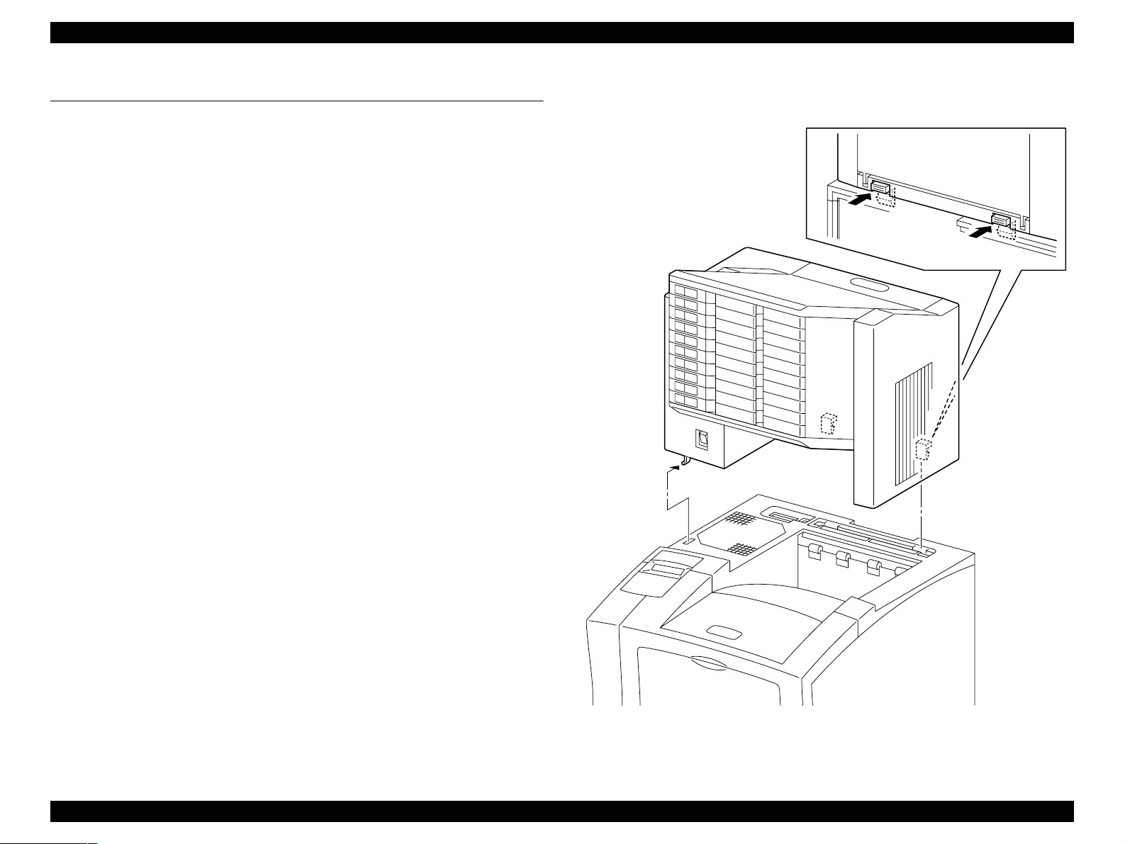
1.1 Installation and Removal of Multibin Unit
1.1.1 Installation
1. Switch off the printer’s power.
2. Place one hand under the Multibin Unit Bins and the other hand on the
Chute Rear handle.
3. Position the Multibin Unit over the printer.
4. Slide the positioning hook into the slot on the printer Cover Assy Top.
5. Lower the rear of the Multibin Unit onto the Cover Assy Top, carefully
lining up the P/J at the bottom rear of the Multibin Unit with the
corresponding P/J in the open Cover Option hole.
6. Press down on the rear of Multibin Unit until it snaps into place on the
Cover Assy Top.
7. Reconnect all AC power cords to the rear of the Multibin Unit.
1.1.2 Removal
1. Make sure the printer is off.
NOTE: Place a thick plate under the bottom plate of Multibin Unit to
protect metallic hook and the Chute Lower and the P/J
connector at the bottom of Multibin Unit.
2. Disconnect all AC power cords from the rear of the Multibin Unit.
3. Press the two latches that are located at the bottom-rear of the Multibin
Unit while you lift up the rear of the Multibin Unit.
4. Slide the positioning hook out of the Cover Assy Top and remove the
Multibin Unit.
NOTE: Mount the Cover Option on t he Cover Assy Top, if the Mu ltibin
Unit is removed from the printer for a long time.
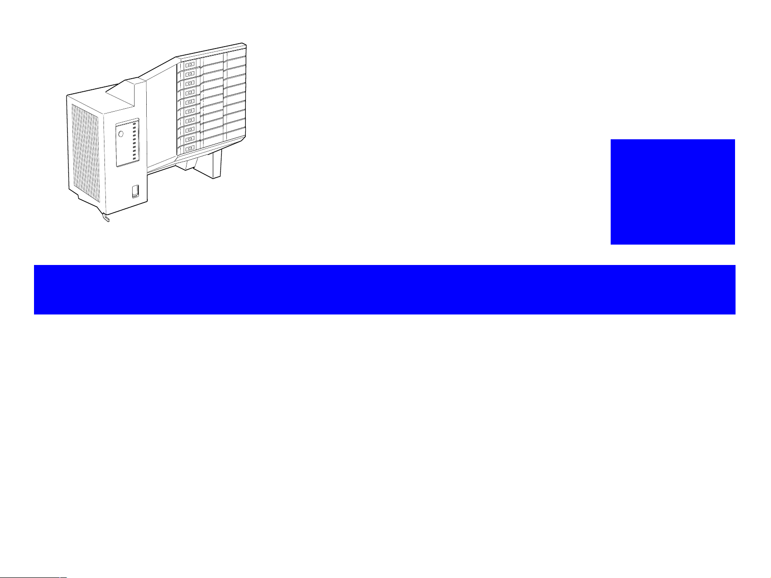
Figure 1-1. Multibin Unit
Multibin Unit Installation and Removal of Multibin Unit 10
Page 11
EPSON EPL-N2050 Optional Units Revision B
1.2 Specifications
1.2.1 Features
o The Mult ibin Unit is installed on top of the printer. This Unit is
electrically connected to the printer by connectors, and when the
printer is switched on, it can automatically detect if the Multibin Unit
is installed, and each bin is full or not full, on condition t hat the switch
of the Multibin Unit is on before the printer is turned on.
o The Mu ltibin Unit has independ ent drive and logic. The switching flap
installed in the upper part of the printer switches the paper path
between the printer output tray and the Multibin Unit.
o Each bin can hold up to 45 sheets of paper, and the entire Unit can
hold a total of 450 sheets (See Table 1-1 on the right).
o Bins are drawer-type trays that are locked by solenoid and lock levers
all the time. All ten bins can be unlocked by pressing the Multibin
Open button.
o Pass word to open e ach bin can be s et. Once pa sswords ar e set for the
bins, only the authenticated bin can be unlocked.
1.2.2 Basic Specification
o Name Multibin Unit
o Paper Output Method
Straight Output, Switching Flap
o Installation Installed on top of the printer exit (desk top type
installed by users)
o Drive Method Built-in Motor Drive
o Interface Transmit: Installation of the Unit, bin full,
bin open/closed.
Receive: Signal to determine which bin paper
should be output to.
o Paper Type / Size Standard paper, normal paper (60-105g/m
16-28lb), special paper, and A4 or Letter (LT)
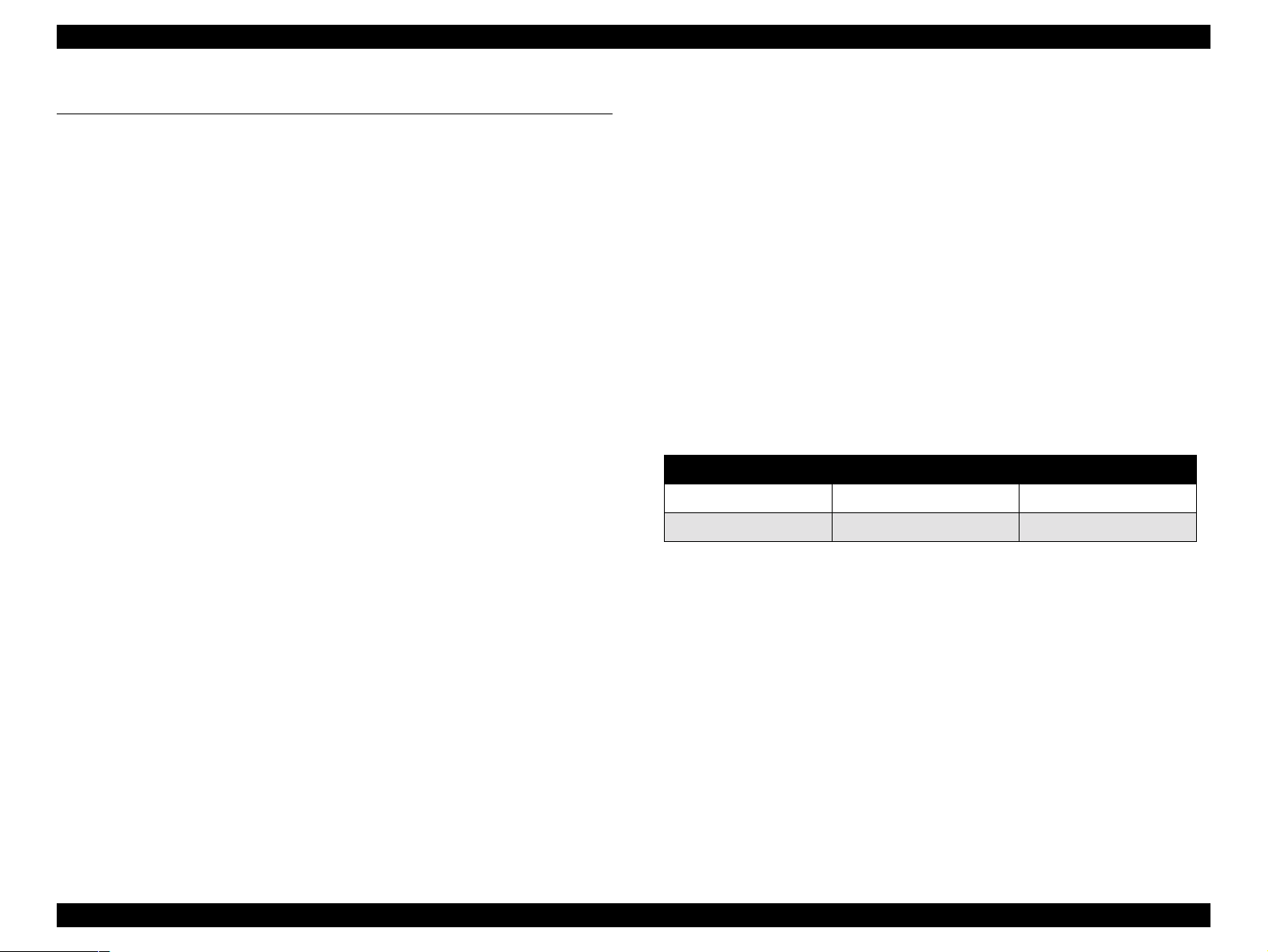
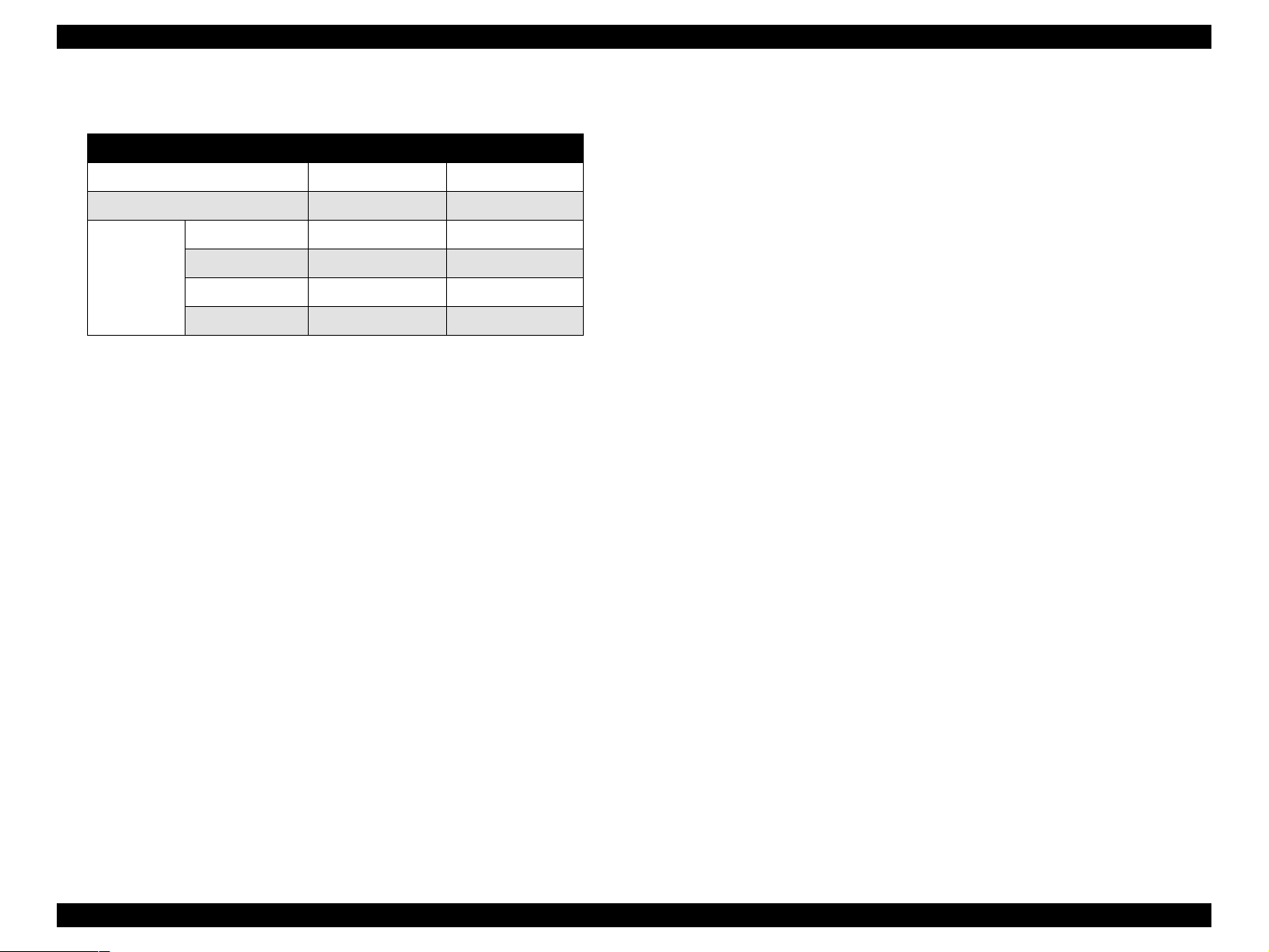
o Capacity
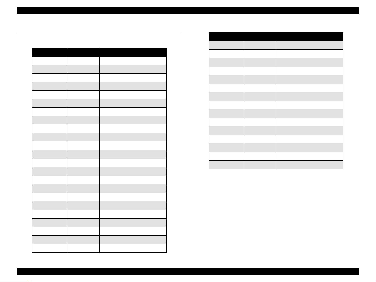
Table 1-1. Capacity
Condition Capacity of Each Bin Total Capacity (10 bins)
10°C/30% to 27°C/65% 45 sheets 450 sheets
28°C/85% 30 sheets 300 sheets
2
:
NOTE: When standard paper is used.
o Paper Fe ed Standard Center-line reference for each paper size
o Detection Structure
n
Paper Full: Automatic detection by Photo Sensor + Actuator
n
Bin Open/Closed: Automatic detection by Micro Switch
o Dimension 403mm (W) x 360mm (D) x 364 mm (H)*
*Protrusions at the bottom of the Unit are not
included.
o Weight 9.2 kg
o Acoustic Noise Max. of 51.5db (A) when instald on the printer.
(Based on ISO7779)
Multibin Unit Specifications 11
Page 12
EPSON EPL-N2050 Optional Units Revision B
o Power Consumption
Table 1-2. Power Consumption
100V/115V 220V/240V
Maximum 74W 69W
Average (Continuous Printing) 36W 37W
All bins closed* 8W 12W
Average
(Stand-by)
*When Energy Star Mode is used.
1 bin open 17W 20W
5 bin open 33W 34W
All bins open (TBD) (TBD)
o Power Supply
Universal type which meets the following specifications:
100V Model: 100V/120V 90V-140V (50/60Hz ±3%)
200V Model: 220V/240V 198V-264V (50Hz ±3%)
1.2.3 Paper Specification
o Supported Paper Type
n
Standard Paper: LT: Xerox-4024
A4: Xerox-RX80, FX-L
n
Normal Paper: 60-105g/m2 (16-28lb)
Commonly used copy paper, bond paper, and
recycled paper
n
Special Paper: Labels, OHP Films
o Supported Paper Size
n
Letter (216 x 279mm: 8.5 x 11”)
n
A4 (210 x 297mm)
NOTE: Use of paper other than the above size will cause paper jam,
or such paper cannot be removed from the paper exit tray
easily.
It is therefore necessary to reject such paper the controller
operation.
Multibin Unit Specifications 12
Page 13
EPSON EPL-N2050 Optional Units Revision B
1.2.4 Reliability, Dur ability, Serviceab i li ty
o MPBF 300,000 pages
o Printing Volume Maximum 25,000 pages/month
Average 5,000 pages/month
o Paper Feeding Reliability
o Jam Rate (Condition: 18-27°C/20-65%)
One-side Printing Duplex Printing
Standard Paper 1/5000 1/3333
o Durability 600,000 pages or 5 years, whichever comes
earlier.
o Serviceability MTTR: Within 30 minutes
1.2.5 Operating Conditions
Refer to Chapter 1 of the printer’s Service Manual.
1.2.6 Electrical Characteristics
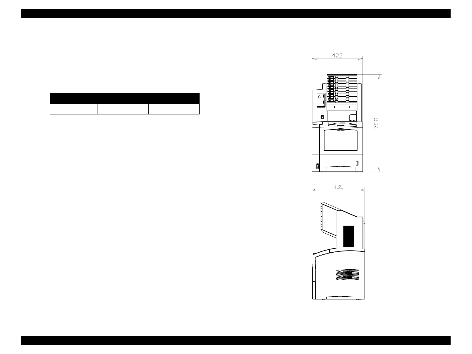
1.2.8 External Dimension
mm
o Leak Current Maximum of 3.5mA (100V/115V)
Maximum of 3.5mA (220V/240V)
Refer to Chapter 1 of the printer’s Service Manual for other items.
1.2.7 Applicable Standards and Regulations
When connected to the printer;
o Safety Regulations (Laser Radiation)
None
Refer to Chapter 1 of the printer’s Service Manual for other items.
Figure 1-2. External Dimension
Multibin Unit Specifications 13
Page 14

EPSON EPL-N2050 Optional Units Revision B
1.2.9 Operating Specification
1.2.9.1 How to Open Bins
1. Display is changed to user authentication mode when the Open button on
the Multibin Unit is pressed.
Display: Enter Password = XXXX
NOTE: When the Open button on the Multibin Unit is pressed, the
LED of the bin(s) for which password is disabled goes on. At
this time, this bin(s) can be opened. If there is no bin for which
password is enab led , Enter Password=XXXX is not displayed,
and Open Multibin Unit is displayed.
2. Enter password by pressing 4 switches, and all bins which matched the
password will open. The LED of the bin(s) that can be opened goes o n,
and Open Multibin Unit is displayed on the LCD.
If the entered password is incorrect, Password Error is displayed for two
seconds, and Enter Pasword=XXXX is once again displayed afterwards.
3. The bin(s) will be automatically locked 20 seconds after the Open button
is pressed. The Unit goes Off-Line when the Open button is pressed, and
for the next 20 seconds, no operation on the panel except for entering
password is possible.
1.2.9.2 Period in which the Multibin Unit can be opened
o Can be opened When the printer is in a status of lower priority
than XXX Error yyy.
o Cannot be opened During the printer is in SelecType mode, or
during printing.
NOTE: Bins can be opened when the Multibin Unit is not installed on
the printer (mechanical specification).
1.2.9.3 Display of Each Bin’s LED
o Paper Loaded: -
o Locked: Off
o Unlocked: On
o Full: Flash
The bin which is opened at that time will be locked immediately after it is
closed.
If no password is entered and 20 seconds passed after Enter
Password=XXXX is displayed, LCD display returns to the normal state.
NOTE: Bins can be opened during the following period:
20 seconds minus time required from the moment the Open
button is pressed until the password is authenticated.
From the moment the password is authenticated until the bin
will automatically locked, no operation on the panel is
possible.
Multibin Unit Specifications 14
Page 15
EPSON EPL-N2050 Optional Units Revision B
1.3 Troubleshooting
1.3.1 If Paper Jam Occured Inside a Tray
1. Switch off the Multibin Unit and disconnect the power cable.
2. Remove the Unit from the printer.
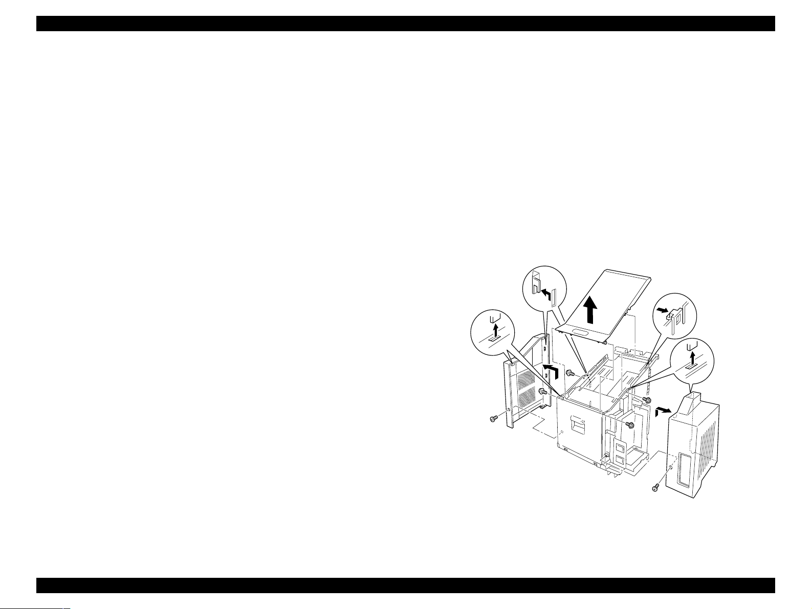
3. Remove the housing parts (Cover Left, Cover Right, and Cover Top) by
releasing the screws.
4. Remove the Stopper Tray (L & R).
5. Unlock the corresponding Stopper Key by releasing the solenoid.
6. Draw out the corresponding tray and take out the jammed paper.
7. Reassemble and install the Unit.
CAUTION
This operation is for service personnel only.
Figure 1-3. Cover Left, Cover Right, Cover Top
Multibin Unit Troubleshooting 15
Page 16

EPSON EPL-N2050 Optional Units Revision B
1.4 Disassembly and Assembly
This section contains the removal and assembly procedures for the Multibin Unit option.
1.4.1 Preparation
Before you begin any Removal and Assembly Procedure;
1. Switch OFF the main power.
2. If this manual instructs you to remove the Multibin Unit from the base
engine, place the Multibin Unit on a stable worktable.
3. Unless otherwise specified, position the Multibin Unit so the rear,
including the Low Chute and the P/J connector, hang over the edge of the
worktable.
4. Wear an electrostatic discharge wrist strap to protect sensitive Multibin
Unit parts from damage.
1.4.2 Notations in the Manual
o Arrows in an illustrat ion show direct ion of m ovement when r emoving
a component.
o Slas hes in a p art name indicate that n ume rous com ponents sha re the
same heading and function. For example, “Gears In/Feed/O ut” refers
to Gear In, Gear Feed, and Gear Out.
Multibin Unit Disassembly an d A s se mbly 16
Page 17
EPSON EPL-N2050 Optional Units Revision B
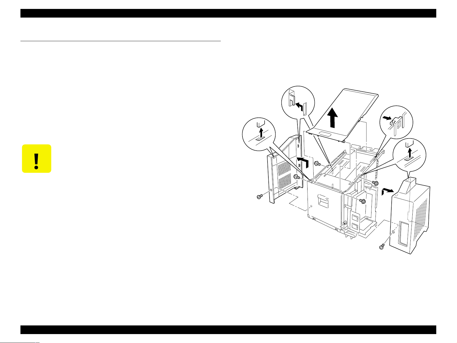
1.4.3 Cover Left, Cover Top and Cover Right
1.4.3.1 Removal
1. Remove the Multibin Unit from the base engine. (See “Removal” on
page 10)
2. Remove the screw (located at the rear of the Cover Left) that is securing
the Cover Left to the Multibin Unit.
3. Slide the Cover Left up, and remove it. (See “Cover Left, Cover Top and
Cover Right” on page 17)
4. Remove the screw (located at the rear of the Cover Right) that is securing
the Cover Right to the Multibin Unit.
5. Slide the Cover Right up, and remove it.
6. Remove the four screws that secure the Cover Top to the Multibin Unit.
7. Open the Chute Rear.
8. Open the Stopper Key Lock R, and push a screwdriver into a square hole
in the Stopper Key Lock R.
9. Press the Solenoid Assy Link to unlock the Multibin Unit Bins and pull out
the top Bin.
10. Release the two Cover Top latches (accessed through the open Bin), and
carefully lift the front of the Cover Top off of the Multibin Unit.
6. Use four screws to secure the Cover Top to the Multibin Unit.
7. Position the Cover Left at the top of the right side of the Multibin Unit.
8. Slide the Cover Left down, repositioning as necessary to clear the LCD
Panel at the front, and the AC receptacles at the rear.
9. Use one screw to secure the Cover Left to the Multibin Unit.
10. Position the Cover Right at the top of the left side of the Multibin Unit.
11. Slide the Cover Right down.
12. Use one screw to secure the Cover Right to the Multibin Unit.
13. Close the Chute Rear.
14. Reinstall the Multibin Unit onto the base engine. (See “Installation” on
page 10)
11. Remove the Cover Top. (See “C over Left, Cover Top and Cover Right” on
page 17)
1.4.3.2 Assembly
1. Remove the screwdriver wedging open Stopper Key Lock R and allow the
Lock to close.
2. Open the Chute Rear.
3. Position the rear of the Cover Top at the rear of the Multibin Unit.
4. Snap the rear into place first, the lower the Cover Top onto the Multibin
Unit.
5. Press down on the Cover Top until it snaps into place.
Multibin Unit Disassembly an d A s se mbly 17
Figure 1-4. Cover Left, Cover Top, Cover Right
Page 18
EPSON EPL-N2050 Optional Units Revision B
1.4.4 Chute Rear and Chute Assy Lower
(with 7-10, 24)
1.4.4.1 Removal
1. Remove the Multibin Unit from the base engine. (See “Removal” on
page 10)
2. Remove the Cover Left and Cover Right. (See “Cover Left, Cover Top and
Cover Right” on page 17)
3. Position the Multibin Unit so the rear of the Multibin Unit hangs over the
edge of the worktable.
4. Open the Chute Rear.
5. Remove the screw that is securing the Support Tape to the Chute Rear.
6. Remove two screws securing the Eliminator S to the Chute Assy Lower,
and remove the Eliminator S.
7. Remove two screws securing the Eliminator to the Chute Assy Lower,and
remove the Eliminator.
8. Close the Chute Rear.
9. Remove the two screws (one at each end of the Chute Assy Lower) that
are securing the Chute Assy Lower to the Multibin Unit.
6. Secure the Eliminator S to the Chute Assy Lower with two screws.
7. Use one screw to secure the Support Tape to the Chute Rear.
8. Close the Chute Rear.
9. Reinstall the Cover Left and Cover Right. (See “Cover Left, Cover Top and
Cover Right” on page 17)
10. Reinstall the Multibin Unit onto the base engine. (See “Installation” on
page 10)
10. Remove the Chute Assy Lower. (See “Chute Rear and Chute Assy Lower (with 7-10, 24)” on page 18)
11. Remove the Chute Rear.
1.4.4.2 Assembly
1. Reinstall the Chute Rear (See the illustration for correct positioning). (See
“Chute Rear and Chute Assy Lower (with 7-10, 24)” on page 18)
2. Reinstall the Chute Assy Lower (See the illustration for correct
positioning).
3. Use two screws to secure the Chute Assy Lower to the Multibin Unit.
4. Open the Chute Rear.
5. Secure the Eliminator to the C hute Assy Lower with two screws.
Multibin Unit Disassembly an d A s se mbly 18
Figure 1-5. Chute Rear and Chute Assy Lower
Page 19
EPSON EPL-N2050 Optional Units Revision B
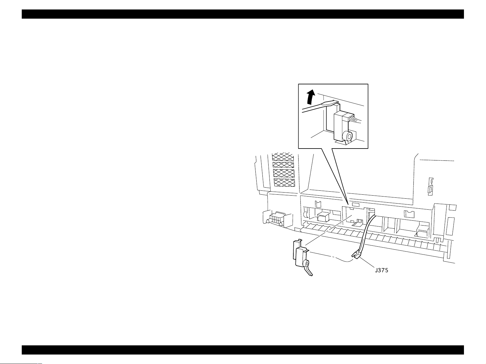
1.4.5 Sensor Pass INT
1.4.5.1 Removal
1. Remove the Multibin Unit from the base engine. (See “Removal” on
page 10)
2. Position the Multibin Unit so it is resting on the Chute Rear.
3. Disconnect J375 from the Sensor Pass INT.
4. Use a small, flat screwdriver blade to pry the upper part of the Sensor
Pass INT away from the Multibin Unit, and remove the Sensor.
1.4.5.2 Assembly
1. Position the Multibin Unit so it is resting on the Chute Rear.
2. Reinstall the lower part of the Sensor Pass INT (the bottom clip and the
sensor actuator arm) into the corresponding holes in the Multibin Unit.
3. Press the upper part of the Sensor against the Multibin Unit.
4. Use a small, flat screwdriver blade to press down on the upper clip so it
slips into the corresponding hole in the Multibin Unit.
5. Make sure the Sensor actuator moves freely and does not bind.
6. Reconnect J375.
7. Reinstall the Multibin Unit onto the base engine. (See “Installation” on
page 10)
Figure 1-6. Sensor Pass INT
Multibin Unit Disassembly an d A s se mbly 19
Page 20

EPSON EPL-N2050 Optional Units Revision B
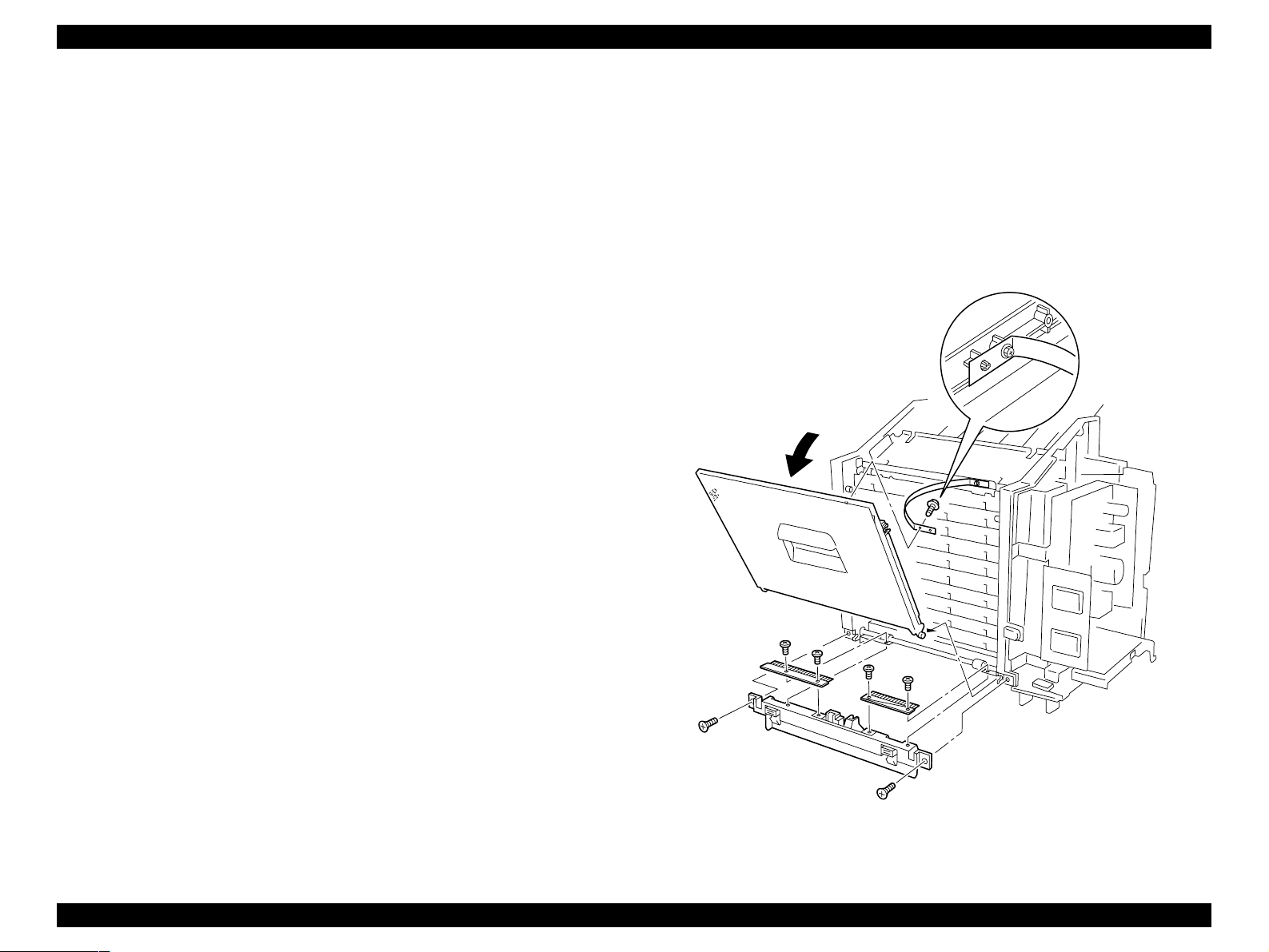
1.4.6 Tray Assy Multibin Unit 2 (with 36-38): Tray1-9 and
Tray Assy Multibin Unit 1 (with 37, 38, 42): Tray10
1.4.6.1 Removal
1. Remove the Multibin Unit from the base engine. (See “Removal” on
page 10)
2. Remove the Left, Right, and Cover Tops.
3. Remove the two screws that are securing the Stopper Tray: Left to the
Multibin Unit frame.
4. Squeeze the latches at the top of the Stopper and remove the Stopper
Tray: Left from the frame.
5. Remove the two screws that are securing the Stopper Tray: Right to the
Multibin Unit frame.
6. Squeeze the latches at the top of the Stopper and remove the Stopper
Tray: right from the frame.
7. Remove the four screws that secure the Plate Assy Top to the Multibin
Unit.
8. Keep the Chute Rear closed during the remainder of this Removal
Procedure.
NOTE: With the Plate Assy Top removed, the ten Gates and ten Roll
Exits tend to slip out of place unless the Chute Rear is closed.
9. Press in on the Solenoid Assy R plunger to open the Stopper Key Lock R.
1.4.6.2 Assembly
1. Open the Chute Rear.
2. Slide the first Tray half-way into the lowest vacant slot in the Multibin
Unit.
3. Lift the Link Assy Paper L and Link Assy Paper R out of the way.
4. Slide the first Tray all the way into the slot, making sure the Sensor S tack
Full actuator does not hang up on the edge of the Tray.
5. Lower one Link Assy Paper L and one Link Assy Paper R onto the bed of
the reinstalled Tray.
6. Slide the next Tray all the way into the slot, making sure the Sensor Stack
Full actuator does not hang up on the edge of the Tray.
7. Lower one Link Assy Paper L and one Link Assy Paper R onto the bed of
the reinstalled Tray.
8. Repeat this process until all of the Trays are reinstalled in the Multibin
Unit.
9. Remove the screwdriver wedging open Stopper Key Lock R and allow the
Lock to close.
10. Reinstall the Plate Assy Top.
11. Use four screws to secure the Plate Assy Top to the Multibin Unit.
10. Use a screwdriver to wedge the Stopper Key Lock R open.
11. Starting with the top Solenoid Assy L, press in and hold the Solenoid
plunger as you slide out the top Multibin Unit tray.
12. Repeat step 10 until you have rem oved all, or the necessary, Multibin Unit
trays.
NOTE: Do not fully tighten the screws at this time.
12. Carefully examine the Gates and Roll Exits.
13. Replace any Gates or Roll Exits that may have been dislodged during Tray
removal or reinstallation.
14. Once all of the Gate and Roll Exits are in place, tighten the four screws
that secure the Plate Assy Top to the Multibin Unit.
15. Reinstall the Stopper Tray: right into the cutouts in the Multibin Unit
frame.
Multibin Unit Disassembly an d A s se mbly 20
Page 21
EPSON EPL-N2050 Optional Units Revision B
16. Use two screws to secure the Stopper Tray: right.
17. Reinstall the Stopper Tray: left into the cutouts in the Multibin Unit frame.
18. Use two screws to secure the Stopper Tray: left.
19. Reinstall the Left, Right, and Cover Tops.
20. Reinstall the Multibin Unit onto the base engine. (See “Installation” on
page 10)
Figure 1-7. Tray Assy Multibin Unit 2 (with 36-38): Tray1-9 and
Tray Assy Multibin Unit 1 (with 37, 38, 42): Tray10
Multibin Unit Disassembly an d A s se mbly 21
Page 22
EPSON EPL-N2050 Optional Units Revision B
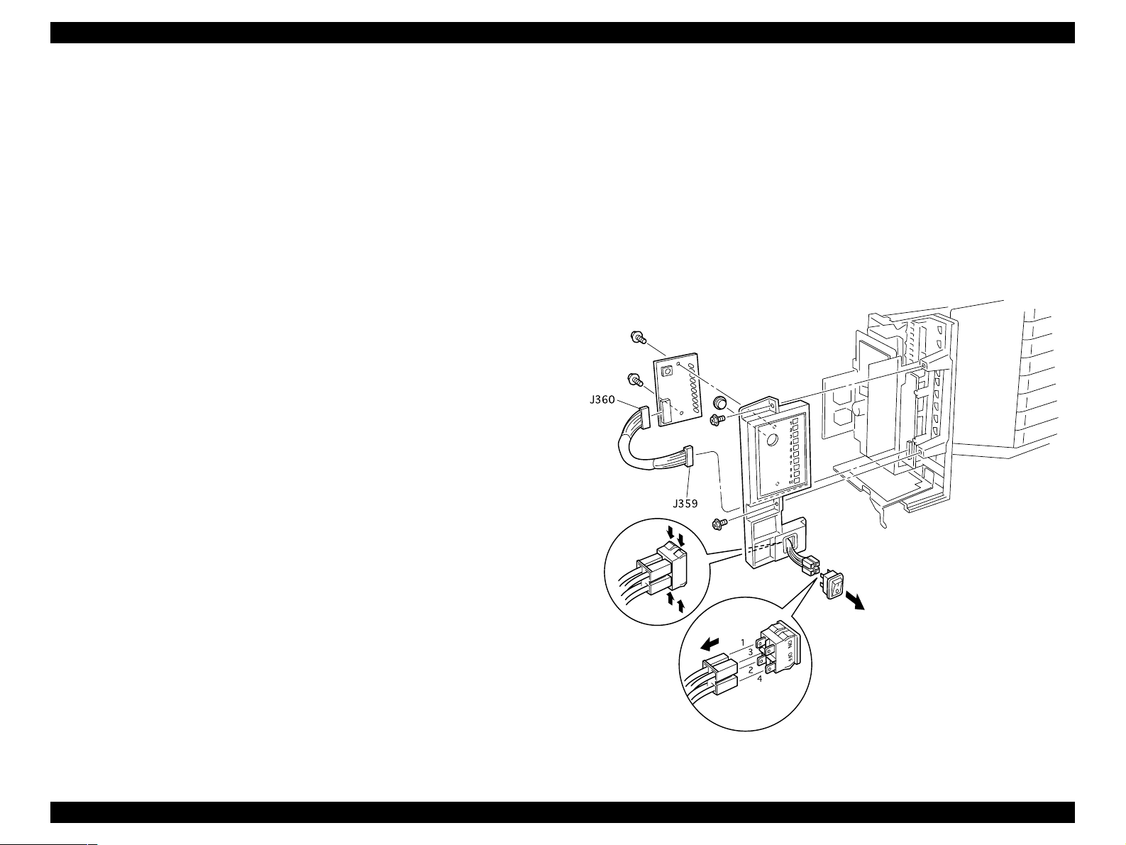
1.4.7 Panel Assy, PWBA LED, and Switch Main
1.4.7.1 Removal
1. Remove the Multibin Unit from the base engine. (See “Removal” on
page 10)
2. Remove the Cover Left. (See “Cover Left, Cover Top and Cover Right” on
page 17)
3. Remove the two screws that are securing the Panel Assy Indicator to the
Multibin Unit frame.
4. Disconnect J359 from the PWBA Main.
5. Disconnect the P/J that is attached to the Switch Main.
6. Remove the Panel Assy Indicator.
7. Remove the two screws that are securing the PWBA LED to the Panel
Assy Indicator, and remove the PWBA LED.
8. Disconnect J360 from the PWBA LED
9. Press in on the latches that secure the Switch Main to the Panel Assy
Indicator, and remove the Switch.
1.4.7.2 Assembly
8. Reinstall the Panel Assy Indicator onto the Multibin Unit frame, by first
sliding the tab that is located at the bottom of the Panel into the
corresponding hole in the Multibin Unit frame, then sliding the Panel into
position.
9. Use two screws to secure the Panel Assy Indicator to the Multibin Unit
frame.
10. Reinstall the Cover Left. (See “Cover Left, Cover Top and Cover R ight” on
page 17)
11. Reinstall the Multibin Unit onto the base engine. (See “Installation” on
page 10)
1. Reinstall the Switch Main into the opening in the Panel Assy Indicator.
Position the Switch Main so the O is at the bottom and the l is on the top.
2. Reinstall the Button into the opening in the Panel Assy Indicator.
3. Reconnect the PWBA LED Harness to J360 on the PWBA LED.
4. Reinstall the PWBA LED into the Panel Assy Indicator, making sure the
LEDs on the PWB fit into the square opening on the back of the Panel
Assy Indicator.
5. Use two screws to secure the PWBA LED to the Panel Assy Indicator.
6. Reconnect the four wire P/J to the Switch Main.
7. Reconnect J359 to the PWBA Main.
Figure 1-8. Panel Assy, PWBA LED, and Switch Main
Multibin Unit Disassembly an d A s se mbly 22
Page 23

EPSON EPL-N2050 Optional Units Revision B
1.4.8 Frame Assy LVPS
1.4.8.1 Removal
1. Remove the Multibin Unit from the base engine. (See “Removal” on
page 10)
2. Remove the Cover Left. (See “Cover Left, Cover Top and Cover Right” on
page 17)
3. Remove the Panel Assy Indicator. (See “Panel Assy, PWBA LED, and
Switch Main” on page 22)
4. Squeeze the tie wrap latch to release the tie wrap from the Multibin Unit
frame, and remove the tie wrap and harness from the frame.
5. Disconnect J350 from the PWBA LVPS.
6. Remove the four screws (1 through 4) that are securing the Frame Assy
LVPS to the Multibin Unit frame.
7. Remove ground wires T351 and T355 from the PWBA LVPS (secured by
screw 3).
8. Remove the screw that is securing ground wire T300 (item I) to the PWBA
LVPS and remove the wire.
NOTE: The screw that secures T300 to the PWBA LVPS is different
from the other screws on the PWBA LVPS. Do not substitute
screws.
9. Remove the screw that is securing ground wire T353 (item S) to the
PWBA LVPS and remove the wire.
1.4.8.2 Assembly
1. Reinstall the Frame Assy LVPS onto the Multibin Unit frame.
2. Reinstall ground wire T353 (item S) onto the PWBA LVPS and secure it
with one screw.
3. Reinstall ground wire T300 (item I) onto the PWBA LVPS and secure it
with one screw.
NOTE: The screw that secures T300 onto the PWBA LVPS is different
from the other screws on the PWBA LVPS. Do not substitute
screws.
4. Reinstall the ground wires T351 and T355 onto the PWBA LVPS at screw
hole 3, and secure them with one screw.
5. Use the other three screws to secure the PWBA LVPS to the Multibin Unit
frame.
6. Reconnect J350 to the PWBA LVPS.
7. Press the tie wrap, with the wire harness, into the hole in the Multibin
Unit frame.
8. Reinstall the Panel Assy Indicator. (See “Panel Assy, PWBA LED, and
Switch Main” on page 22)
9. Reinstall the Cover Left. (See “Cover Left, Cover Top and Cover Right” on
page 17)
10. Reinstall the Multibin Unit onto the base engine. (See “Installation” on
page 10)
10. Remove the Frame Assy LVPS from the Multibin Unit frame.
Multibin Unit Disassembly an d A s se mbly 23
Page 24

EPSON EPL-N2050 Optional Units Revision B
Figure 1-9. Frame Assy LVPS
Multibin Unit Disassembly an d A s se mbly 24
Page 25
EPSON EPL-N2050 Optional Units Revision B
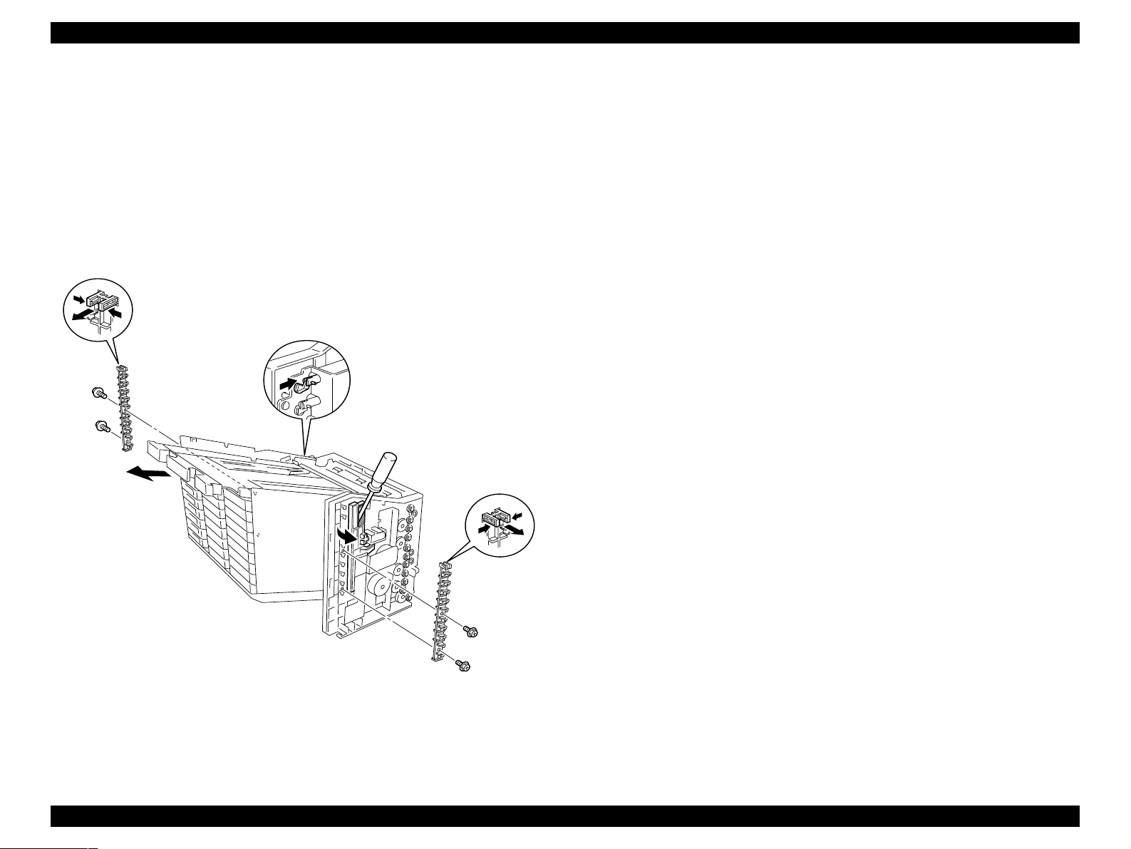
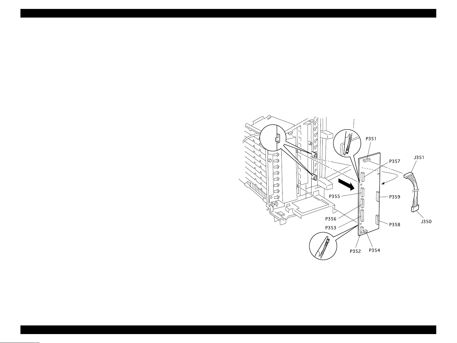
1.4.9 PWBA Main
1.4.9.1 Removal
1. Remove the Multibin Unit from the base engine. (See “Removal” on
page 10)
2. Remove the Cover Left. (See “Cover Left, Cover Top and Cover Right” on
page 17)
3. Remove the Panel Assy Indicator. (See “Panel Assy, PWBA LED, and
Switch Main” on page 22)
4. Remove the Frame Assy LVPS. (See “Frame Assy LVPS” on page 23)
5. Disconnect all of the P/Js that are attached to the PWBA Main.
P/Js 351, 352, 353, 354, 355, 356, 357, 358
6. Press in on the two latches that secure the left side of the PWBA Main to
the Multibin Unit frame, and pull free the left side of the PWB.
7. Slide the right side of the PWB out from under the two tabs that are
located on the right.
8. Remove the PWBA Main.
1.4.9.2 Assembly
7. Reinstall the Cover Left. (See “Cover Left, Cover Top and Cover Right” on
page 17)
8. Reinstall the Multibin Unit onto the base engine. (See “Installation” on
page 10)
1. Slide the right side of the PWBA Main under the two tabs that are located
on the right.
2. Position the two holes in the left side of the PWBA Main with the two
latches on the Multibin Unit frame.
3. Press the left side of the PWBA Main onto the tabs until the PWB snaps
into place.
4. Reconnect all of the P/Js that were attached to the PWBA Main.
P/Js 351, 352, 353, 354, 355, 356, 357, 358
5. Reinstall the Frame Assy LVPS. (See “Frame Assy LVPS” on page 23)
6. Reinstall the Panel Assy Indicator. (See “Panel Assy, PWBA LED, and
Switch Main” on page 22)
Figure 1-10. PWBA Main
Multibin Unit Disassembly an d A s se mbly 25
Page 26

EPSON EPL-N2050 Optional Units Revision B
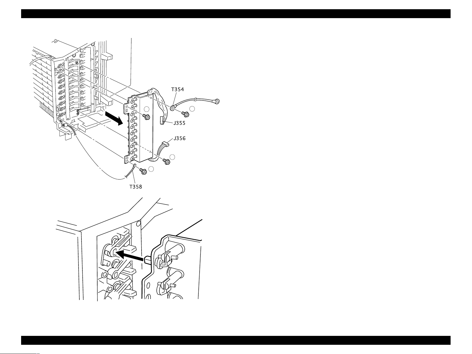
1.4.10 Solenoid Assy Link (with 23-25)
1.4.10.1 Removal
1. Remove the Multibin Unit from the base engine. (See “Removal” on
page 10)
2. Remove the Cover Left. (See “Cover Left, Cover Top and Cover Right” on
page 17)
3. Remove the Panel Assy Indicator. (See “Panel Assy, PWBA LED, and
Switch Main” on page 22)
4. Remove the Frame Assy LVPS. (See “Frame Assy LVPS” on page 23)
5. Remove the PWBA Main. (See “PWBA Main” on page 25)
6. Remove the four screws that are securing the Solenoid Assy L to the
Multibin Unit frame.
NOTE: The top right screw also secures the ground wire T354 to the
Assembly.
NOTE: The bottom left screw also secures the ground wi re T358 to
the Assembly.
7. Pull the Solenoid Assy Link straight out, and remove it from the Multibin
Unit frame.
6. Reinstall the green ground wire T354 against the top right screw hole in
the Solenoid Assy Link.
7. Use one screw to secure the ground wire and the Assembly to the
Multibin Unit frame (item 1).
8. Reinstall the ground wire T358 against the bottom left screw hole in the
Solenoid Assy Link.
9. Use one screw to secure the ground wire and the Assembly to the
Multibin Unit frame (item 4).
10. Reinstall the PWBA Main. (See “PW BA Main” on page 25)
11. Reinstall the Frame Assy LVPS. (See “Frame Assy LVPS” on page 23)
12. Reinstall the Panel Assy Indicator. (See “Panel Assy, PWBA LED, and
Switch Main” on page 22)
13. Reinstall the Cover Left. (See “Cover Left, Cover Top and Cover R ight” on
page 17)
14. Reinstall the Multibin Unit onto the base engine. (See “Installation” on
page 10)
1.4.10.2 Assembly
1. Reinstall the Solenoid Assy Link onto the Multibin Unit frame.
2. Slide the plunger out of each of the ten solenoids.
3. Align each of the ten LInk Solenoids with the ten corresponding openings
in the Gates.
NOTE: If any one of the ten Links fails to line up with the
corresponding Gate opening, you will not be able to correct
seat the Solenoid Assy Link.
4. Press the Solenoid Assy Link against the Multibin Unit frame.
5. Use two screws to secure the Solenoid Assy Link to the Multibin Unit
frame.
Multibin Unit Disassembly an d A s se mbly 26
Page 27
EPSON EPL-N2050 Optional Units Revision B
2
3
4
1
Figure 1-11. Solenoid Assy Link (with 23-25)
Multibin Unit Disassembly an d A s se mbly 27
Page 28

EPSON EPL-N2050 Optional Units Revision B
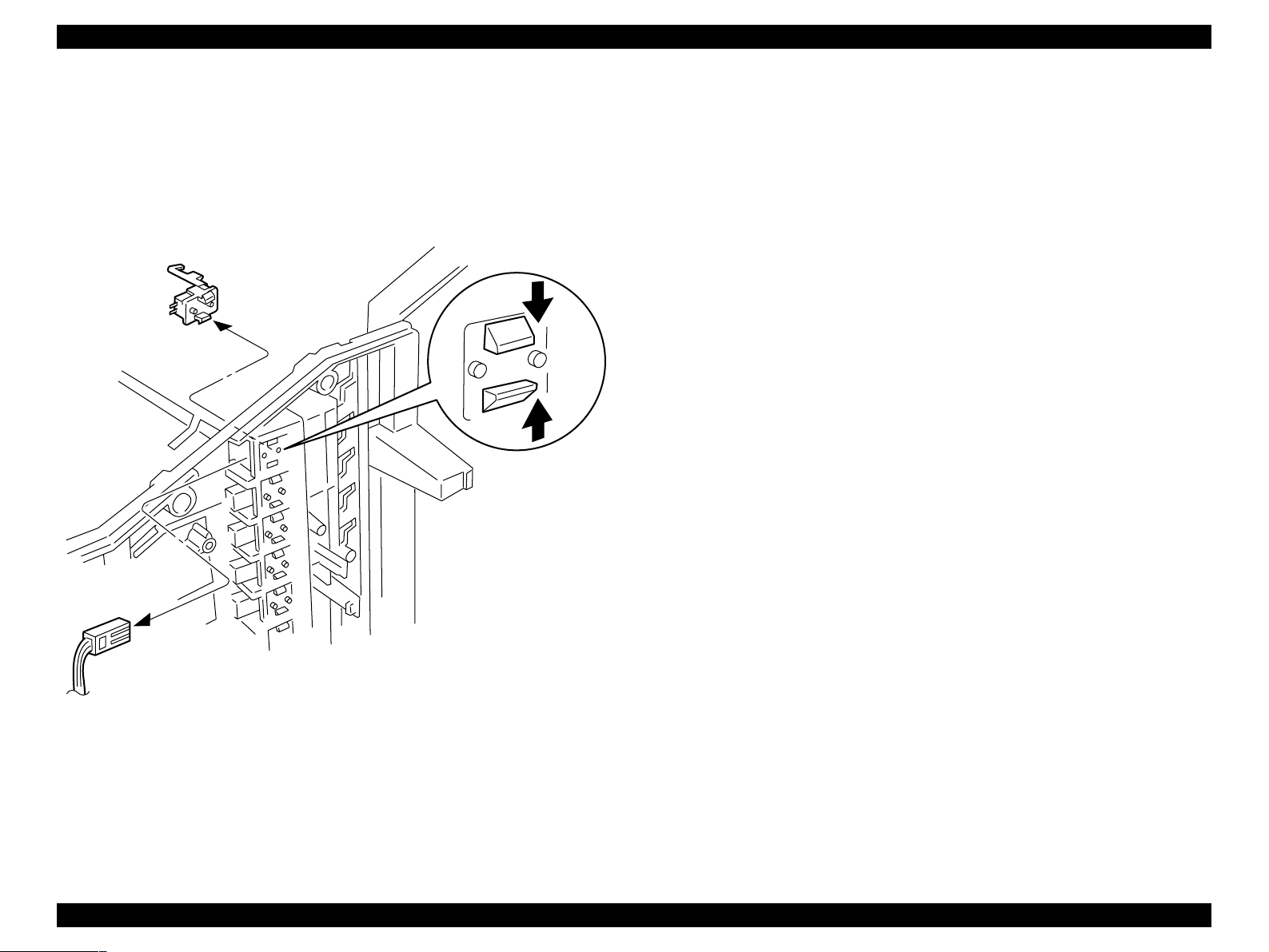
1.4.11 Sensor Stack Full
1.4.11.1 Removal
1. Remove the Multibin Unit from the base engine. (See “Removal” on
page 10)
2. Remove the Cover Left. (See “Cover Left, Cover Top and Cover Right” on
page 17)
3. Remove the Panel Assy Indicator. (See “Panel Assy, PWBA LED, and
Switch Main” on page 22)
4. Remove the Frame Assy LVPS. (See “Frame Assy LVPS” on page 23)
5. Remove the PWBA Main. (See “PWBA Main” on page 25)
6. Remove the Solenoid Assy Link.
7. Remove all of the Multibin Unit Trays necessary to access the Sensor
Stack Full that you want to remove.
8. Disconnect the P/J that is attached to the Sensor Stack Full you want to
remove.
9. Press in on the latches that secure the Sensor Stack Full to the Multibin
Unit frame and pull the Sensor Stack Full in the direction of the Multibin
Unit Trays.
10. Remove the Sensor Stack Full.
1.4.11.2 Assembly
3. Reconnect the P/J to the Sensor.
The P/Js are numbered:
P/J361 goes to Sensor Stack Full 1 (the top Sensor).
P/J362 goes to Sensor Stack Full 2.
P/J363 goes to Sensor Stack Full 3.
P/J364 goes to Sensor Stack Full 4.
P/J365 goes to Sensor Stack Full 5.
P/J366 goes to Sensor Stack Full 6.
P/J367 goes to Sensor Stack Full 7.
P/J368 goes to Sensor Stack Full 8.
P/J369 goes to Sensor Stack Full 9.
P/J370 goes to Sensor Stack Full 10 (the bottom Sensor).
4. Reinstall the Multibin Unit Trays.
5. Reinstall the Solenoid Assy Link.
6. Reinstall the PWBA Main. (See “PWBA Main” on page 25)
7. Reinstall the Frame Assy LVPS. (See “Frame Assy LVPS” on page 23)
8. Reinstall the Panel Assy Indicator. (See “Panel Assy, PWBA LED, and
Switch Main” on page 22)
9. Reinstall the Cover Left. (See “Cover Left, Cover Top and Cover Right” on
page 17)
1. Reinstall the Sensor Stack Full by sliding it from the Tray side, into the
correct Sensor slot. (See the illustration for correct positioning).
2. Press the two tabs and two latches located on the back of the Sensor
Stack Full, into the corresponding holes in the Sensor Stack Full slot.
The Sensor Stack Full snaps into place.
10. Reinstall the Multibin Unit onto the base engine. (See “Installation” on
page 10)
Multibin Unit Disassembly an d A s se mbly 28
Page 29
EPSON EPL-N2050 Optional Units Revision B
Figure 1-12. Sensor Stack Full
Multibin Unit Disassembly an d A s se mbly 29
Page 30
EPSON EPL-N2050 Optional Units Revision B
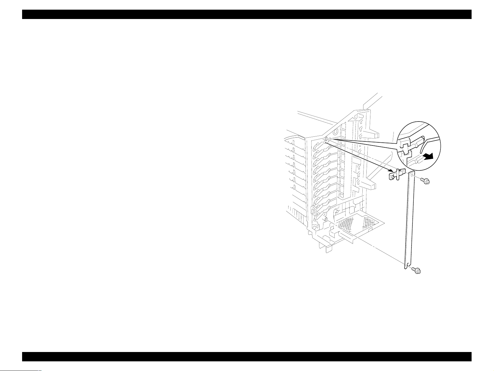
1.4.12 Stopper Key Lock L
1.4.12.1 Removal
1. Remove the Multibin Unit from the base engine. (See “Removal” on
page 10)
2. Remove the Cover Left. (See “Cover Left, Cover Top and Cover Right” on
page 17)
3. Remove the Panel Assy Indicator. (See “Panel Assy, PWBA LED, and
Switch Main” on page 22)
4. Remove the Frame Assy LVPS. (See “Frame Assy LVPS” on page 23)
5. Remove the PWBA Main. (See “PWBA Main” on page 25)
6. Remove the Solenoid Assy Link. (See “Solenoid Assy Link (with 23-25)”
on page 26)
7. Remove the two screws that are securing the Support Key Lock L to the
Multibin Unit frame, and remove the Support.
8. Remove a specific Stopper Key Lock L by lifting it from its slot.
1.4.12.2 Assembly
1. Reinstall the Stopper Key Lock L. (See the illustration for correct
positioning).
9. Reinstall the Multibin Unit onto the base engine. (See “Installation” on
page 10)
2. Reinstall the Support Key Lock L. (See the illustration for correct
positioning).
3. Use two screws to secure the Support Key Lock L.
4. Reinstall the Solenoid Assy Link. (See “Solenoid Assy Link (with 23-25)”
on page 26)
5. Reinstall the PWBA Main. (See “PWBA Main” on page 25)
6. Reinstall the Frame Assy LVPS. (See “Frame Assy LVPS” on page 23)
7. Reinstall the Panel Assy Indicator. (See “Panel Assy, PWBA LED, and
Switch Main” on page 22)
8. Reinstall the Cover Left. (See “Cover Left, Cover Top and Cover Right” on
page 17)
Figure 1-13. Stopper Key Lock L
Multibin Unit Disassembly an d A s se mbly 30
Page 31

EPSON EPL-N2050 Optional Units Revision B
1.4.13 Gate
1.4.13.1 Removal
1. Remove the Cover Right, Cover Top, and Cover Left.
2. Remove the Chute Rear. (See “Chute Rear and Chute Assy Lower (with 710, 24)” on page 18)
3. Slide the Gate to the left.
4. Pull out on the center of the Gate and slide the other end of the Gate out
of the bearing in the Multibin Unit frame and remove the Gate.
5. Repeat this procedure for all of the Link Gates and Gates you want to
remove.
1.4.13.2 Assembly
1. Reinstall the Gate by first inserting the left end of the Gate into the
bearing in the Multibin Unit frame. (See the illustration for correct
positioning).
2. Bow the Gate enough to allow you to slide the right end of the Gate into
the Link Gate.
3. Press down on the Link Gate to make sure the Gate opens and closes
correctly.
4. Reinstall the Chute Rear. (See “Chute Rear and Chute Assy Lower (with 710, 24)” on page 18)
5. Reinstall the Cover Right, Cover Top, and Cover Left.
Figure 1-14. Gate
Multibin Unit Disassembly an d A s se mbly 31
Page 32

EPSON EPL-N2050 Optional Units Revision B
1.4.14 Harness Assy MCU
1.4.14.1 Removal
1. Remove the Multibin Unit from the base engine. (See “Removal” on
page 10)
2. Remove the Cover Left. (See “Cover Left, Cover Top and Cover Right” on
page 17)
3. Remove the Panel Assy Indicator. (See “Panel Assy, PWBA LED, and
Switch Main” on page 22)
4. Remove the Frame Assy LVPS. (See “Frame Assy LVPS” on page 23)
5. Disconnect P352 on the PWBA Main. (See “PWBA Main” on page 25)
6. Remove the screw that is securing ground wire T355 to the frame, and
remove the wire.
7. Position the Multibin Unit on the Cover Left.
8. Use a screwdriver blade to pry up the two Support MCU that secure the
Harness Assy MCU to the Multibin Unit frame.
9. Remove the Harness Assy MCU from the frame.
1.4.14.2 Assembly
9. Reinstall the Multibin Unit onto the base engine. (See “Installation” on page 10)
Make sure J202 mates with P202.
1. Orient the Harness Assy MCU J202 so it mates with P202 on the base
engine.
2. Thread the Harness through the opening in the Multibin Unit frame.
3. Reinstall the J202 into the opening in the Multibin Unit frame.
4. Use two Support MCU to secure J202 to the frame.
5. Reconnect P352 on the PWBA Main. (See “PWBA Main” on page 25)
6. Reinstall the Frame Assy LVPS. (See “Frame Assy LVPS” on page 23)
7. Reinstall the Panel Assy Indicator. (See “Panel Assy, PWBA LED, and
Switch Main” on page 22)
8. Reinstall the Cover Left. (See “Cover Left, Cover Top and Cover Right” on
page 17)
Figure 1-15. Harness Assy MCU
Multibin Unit Disassembly an d A s se mbly 32
Page 33

EPSON EPL-N2050 Optional Units Revision B
1.4.15 Motor Bracket Assembly (with 19, 23, 24, 34)
1.4.15.1 Removal
1. Remove the Multibin Unit from the base engine. (See “Removal” on
page 10)
2. Remove the Cover Right. (See “Cover Left, Cover Top and Cover Right”
on page 17)
3. Cut the tie wrap that secures the wire harness to the Bracket Motor.
4. Disconnect J372 and J373 from the Motor Assys.
5. Disconnect the J374-1 from J374 leading to the Solenoid Assy R.
6. Remove the Solenoid Assy R harness from the Motor Bracket Assembly.
7. Remove the screw that is securing the ground wire T352 to the Motor
Bracket Assembly, and remove the wire.
8. Remove the four screws that are securing the Motor Bracket As se m bl y to
the Multibin Unit frame.
9. Pull the Motor Bracket Assemb ly away from the frame and slightly to the
right to free the two Belt Synchronous from the Gear Pulley 19/42T on the
Motor shafts.
10. Remove the Motor Bracket Assembly by pulling it away from the frame.
1.4.15.2 Assembly
5. Maintain tension on the Motor Bracket Assembly, so the belts do not slip
out of place, and start to press the Motor Bracket Assembly against the
frame.
6. Press down on the ground strap that is located at the top of the Bracket,
and continue pressing the Bracket against the frame so the ground strap
goes under the metal tab that is protruding out of the frame.
7. Press the Bracket firmly against the frame and reposition the Bracket so
all of the screw holes in the Bracket line up with the screw holes in the
frame.
8. Use four screws to secure the Motor Bracket Assembly to the Multibin
Unit frame.
9. Use one screw to secure ground wire T352 to the Motor Bracket
Assembly.
10. Reconnect the J374-1 to J374 leading to the Solenoid Assy R.
11. Reconnect J372 and J373 to the Motor Assy.
12. Dress all of the wires so they are clear of all moving parts and use a tie
wrap to secure the harness (item R).
13. Reinstall the Cover Right. (See “Cover Left, Cover Top and Cover Right”
on page 17)
14. Reinstall the Multibin Unit onto the base engine. (See “Installation” on
page 10)
1. Hold the Solenoid Assy R harness out of the way so it does not get
trapped between the Motor Bracket Assembl y and the Multibin Unit
frame.
2. Position the Motor Bracket Assembly slightly away from the Multibin Unit
frame. (See the illustration for correct positioning).
3. Thread the wire harness through the opening located at the bottom of the
Bracket.
4. Reposition the Motor Bracke t Ass embly so the two Belt synchronous loop
the two Gear Pulley 19/42T on the Motor shafts.
Multibin Unit Disassembly an d A s se mbly 33
Page 34

EPSON EPL-N2050 Optional Units Revision B
Figure 1-16. Motor Bracket Assy (with 19, 23, 24, 34)
Multibin Unit Disassembly an d A s se mbly 34
Page 35

EPSON EPL-N2050 Optional Units Revision B
1.4.16 Solenoid Assy R
1.4.16.1 Removal
1. Remove the Multibin Unit from the base engine. (See “Removal” on
page 10)
2. Remove the Cover Right. (See “Cover Left, Cover Top and Cover Right”
on page 17)
3. Disconnect J374-1 from the in-line connector located near the bottom
Motor.
4. Spread the four latches and pull the Solenoid Assy R way from the frame.
1.4.16.2 Assembly
1. Reinstall the Solenoid Assy R. (See the illustration for correct
positioning).
2. Reposition the Solenoid plunger so the pin is vertical and fits into the slot
in the Stopper Key Lock R.
3. Press the Solenoid Assy R against the Multibin Unit frame so the four
latches snap into place.
4. Press and release the Solenoid plunger to make sure the Stopper Key
Lock R opens and closes correctly.
5. Reconnect J374-1.
6. Reroute the Solenoid Harness so it is away from all moving parts.
7. Reinstall the Cover Right. (See “Cover Left, Cover Top and Cover Right”
on page 17)
8. Reinstall the Multibin Unit onto the base engine. (See “Installation” on
page 10)
Figure 1-17. Solenoid Assy R
Multibin Unit Disassembly an d A s se mbly 35
Page 36

EPSON EPL-N2050 Optional Units Revision B
1.4.17 Belt Synchronous
1.4.17.1 Removal
1. Remove the Multibin Unit from the base engine. (See “Removal” on
page 10)
2. Remove the Cover Right. (See “Cover Left, Cover Top and Cover Right”
on page 17)
3. Remove the Motor Bracket Assembly. (See “Harness Assy MCU” on
page 32)
4. To remove the Belt Synchronous Top:
5. Open the gear latches and remove the Gear Idler 16T 2, 3, 4, and 5
(number 1 is the top gear in the line).
6. Remove the two Gear Idler 30T that contact the Gear Pulley 19/42T:Top.
7. Remove the Gear Pulley 19/42T:Top that is driving the Belt Synchronous:
Top.
8. Remove the Belt Synchronous: Top.
9. To remove the Belt Synchronous Bottom:
10. Open the gear latches and remove the Gear Idler 16T numbers 7, 8, 9, and
10 (number 10 is the bottom gear in the line).
1.4.17.2 Assembly
1. To reinstall the Belt Synchronous Bottom:
2. Loop the belt over the Gear Pulley 19/42T: Bottom. (See the illustration for
correction positioning).
3. Slide the belt and Gear Pulley 19/42T: Bottom onto the large diameter
shaft.
NOTE: The belt should rest against the Multibin Unit frame.
4. Slide two Gear Idler 30T onto the two shafts that are located next to the
Gear Pulley 19/42T: Bottom.
NOTE: The teeth of the Gear Idler 30T should mesh with the teeth of
Gear Pulley 19/42T: Bottom.
5. Position Gear Idler 16T number 10 (the bottom gear in the line) so the
latch faces away from the Multibin Unit frame and the gear teeth face the
Multibin Unit frame.
6. Line up the flat part of the gear hole with the flat part of the shaft, and
slide the Idler Gear onto the shaft.
The Gear latch snaps into place.
7. Repeat these steps and reinstall Gear Idler 16T numbers 9, 8, and 7.
11. Remove the two Gear Idler 30T that contact the Gear Pulley 19/42T:
Bottom.
12. Remove the Gear Pulley 19/42T: Bottom that is driving the Belt
Synchronous: Bottom.
13. Remove the Belt Synchronous: Bottom.
8. To reinstall the Belt Synchronous Top:
9. Loop the belt over the Gear Pulley 19/42T:Top. (See the illustration for
correction positioning).
10. Slide the belt and Gear Pulley 19/42T:Top onto the large diameter shaft.
NOTE: The belt should rest against the Multibin Unit frame.
11. Slide two Gear Idler 30T onto the two shafts that are located next to the
Gear Pulley 19/42T:Top.
NOTE: The teeth of the Gear Idler 30T should mesh with the teeth of
Gear Pulley 19/42T:Top.
Multibin Unit Disassembly an d A s se mbly 36
Page 37

EPSON EPL-N2050 Optional Units Revision B
12. Position Gear Idler 16T number 2 (number 1 is the top gear in the line) so
the latch faces away from the Multibin Unit frame and the gear teeth face
the Multibin Unit frame.
13. Line up the flat part of the gear hole with the flat part of the shaft, and
slide the Gear Idler 16T onto the shaft.
NOTE: The Gear latch snaps into place.
14. Repeat these steps and reinstall Gear Idler 16T numbers 3, 4, and 5.
15. Reinstall the Motor Bracket Assembly. (See “Harness Assy MCU” on
page 32)
16. Reinstall the Cover Right. (See “Cover Left, Cover Top and Cover Right”
on page 17)
17. Reinstall the Multibin Unit onto the base engine. (See “Installation” on
page 10)
Figure 1-18. Belt Synchronous
Multibin Unit Disassembly an d A s se mbly 37
Page 38

EPSON EPL-N2050 Optional Units Revision B
1.4.18 Stopper Key Lock R
1.4.18.1 Removal
1. Remove the Multibin Unit from the base engine. (See “Removal” on
page 10)
2. Remove the Cover Right. (See “Cover Left, Cover Top and Cover Right”
on page 17)
3. Remove the Motor Bracket Assembly. (See “Harness Assy MCU” on
page 32)
4. Remove the Solenoid Assy R. (See “Solenoid Assy R” on page 35)
5. Bow the Stopper Key Lock R and slide the top pivot out of the pivot hole
in the Multibin Unit frame.
6. Remove the Stopper Key Lock R and the attached Spring Lock.
1.4.18.2 Assembly
1. Reinstall the Spring Lock onto the back of the Stopper Key Lock R.
2. Insert the bottom pivot of the Stopper Key Lock R into the pivot hole in
the Multibin Unit frame. (See the illustration for correct positioning ).
3. Press the Stopper Key Lock R against the Multibin Unit frame, making
sure the free end of the Spring Lock fits over the tab on the Multibin Unit
frame.
4. Bow the Stopper Key Lock R and slide the top pivot into the pivot hole in
the Multibin Unit frame.
5. Press and release the Stopper Key Lock R to make sure it moves freely
and has a spring-action return.
6. Reinstall the Solenoid Assy R. (See “Solenoid Assy R” on page 35)
7. Reinstall the Motor Bracket Assembly. (See “Harness Assy MCU” on
page 32)
8. Reinstall the Cover Right. (See “Cover Left, Cover Top and Cover Right”
on page 17)
9. Reinstall the Multibin Unit onto the base engine. (See “Installation” on
page 10)
Figure 1-19. Stopper Key Lock R
Multibin Unit Disassembly an d A s se mbly 38
Page 39

EPSON EPL-N2050 Optional Units Revision B
1.4.19 Roll Assy Transport
1.4.19.1 Removal
1. Remove the Multibin Unit from the base engine. (See “Removal” on
page 10)
2. Remove the Cover Left and Cover Right. (See “Cover Left, Cover Top and
Cover Right” on page 17)
3. Remove the Chute Rear and Chute Assy Lower.
4. Open the gear latch and remove the Gear Idler 16T that is attached to the
Roll Assy Transport (1).
5. Remove the E Ring from the Roll Assy Transport (2).
6. Slide the Bearing out of the bearing hole (3).
7. Slide the Roll Assy Transport to the Right (4), then pull it away from the
Multibin Unit frame (5).
8. Remove an E-ring attached to the left side of Roll Assy Transport. (6)
9. Remove the Roll Assy Transport.
1.4.19.2 Assembly
1. Attach an E-ring to the left side of Roll Assy Transport.
10. Reinstall the Cover Left and Cover Right. (S ee “Cover Left, Cover Top and
Cover Right” on page 17)
11. Reinstall the Multibin Unit onto the base engine. (See “Installation” on
page 10)
2. Reinstall the Bearing 6 into the left bearing hole. (See the illustration for
correct positioning).
3. Slide the Bearing onto the right end of the Roll Assy Transport. (See the
illustration for correct positioning).
4. Slide the right end of the Roll Assy Transport into the right bearing hole.
5. Slide the left end of the Roll Assy Transport into the left bearing.
6. Slide the Bearing along the shaft and into the right bearing hole.
7. Use an E Ring to secure the right end of the Roll Assy Transport.
8. Reinstall the Gear Idler 16T on the right end of the Roll Assy Transport.
9. Reinstall the Chute Rear and Chute Assy Lower.)
Figure 1-20. Roll Assy Transport
Multibin Unit Disassembly an d A s se mbly 39
Page 40

EPSON EPL-N2050 Optional Units Revision B
1.4.20 Roll Exit
1.4.20.1 Removal
1. Remove the Multibin Unit from the base engine. (See “Removal” on
page 10)
2. Remove the Cover Left and Cover Right. (See “Cover Left, Cover Top and
Cover Right” on page 17)
3. Remove the Chute Rear and Chute Assy Lower. (See “Chute Rear and
Chute Assy Lower (with 7-10, 24)” on page 18)
4. Press in on the Solenoid Assy R plunger to open the Stopper Key Lock R.
5. Use a screwdriver to wedge the Stopper Key Lock R open.
6. Press in the Solenoid Assy L plunger to open the Bins, and slide the
Multibin Unit trays out as far as they go.
7. Remove the Gate that is associated with the Roll Exit you want to remove.
8. Remove the Gate just above the Gate you removed in step 2.
9. Open the gear latch and remove the Gear Idler 16T from the Roll Exit you
want to remove (1).
10. Unhook the Link Assy Paper L (2) and the Link Assy Paper R from the Roll
Exit shaft.
11. Remove the E Ring from Right end of the shaft (3).
12. Slide Bearing 6 out of the bearing hole.
13. Slide the Roll Exit to the right (4), then pull it away from the Multibin Unit
frame (5).
1.4.20.2 Assembly
1. Remove the screwdriver wedging open Stopper Key Lock R and allow the
Lock to close.
2. Reinstall the Bearing 6 into the left bearing hole. (See the illustration for
correct positioning).
3. Slide the Bearing onto the right end of the Roll Exit. (See the illustration
for correct positioning).
4. Slide the right end of the Roll Exit into the right bearing hole.
5. Slide the left end of the Roll Exit into the Bearing 6.
6. Slide the Bearing along the shaft and into the right bearing hole.
7. Use an E Ring to secure the right end of the Roll Exit.
8. Reattach the Link Assy Paper L (2) and the Link Assy Paper R to the Roll
Exit shaft.
9. Reinstall the Gear Idler 16T on the right end of the Roll Exit.
10. Reinstall the Gates. (See “Gate” on page 31)
11. Reinstall the Chute Rear and Chute Assy Lower. (See “Chute Rear and
Chute Assy Lower (with 7-10, 24)” on page 18)
12. Reinstall the Cover Left and Cover Right. (S ee “Cover Left, Cover Top and
Cover Right” on page 17)
13. Reinstall the Multibin Unit onto the base engine. (See “Installation” on
page 10)
14. Remove the Roll Exit (6).
Multibin Unit Disassembly an d A s se mbly 40
Page 41

EPSON EPL-N2050 Optional Units Revision B
1
2
3
4
5
6
Figure 1-21. Roll Exit
Multibin Unit Disassembly an d A s se mbly 41
Page 42

EPSON EPL-N2050 Optional Units Revision B
1.4.21 Solenoid Direction
1.4.21.1 Removal
1. Remove the Multibin Unit from the base engine. (See “Removal” on
page 10)
2. Remove the Cover Left and Cover Right. (See “Cover Left, Cover Top and
Cover Right” on page 17)
3. Remove the Chute Rear and Chute Assy Lower.
4. Press in on the Solenoid Assy R plunger to open the Stopper Key Lock R.
5. Use a screwdriver to wedge the Stopper Key Lock R open.
6. Press the Solenoid Assy L plunger to open the Bins, and slide the bottom
three Multibin Unit trays out as far as possible.
7. Remove the bottom four Gates. (See “Gate” on page 31)
8. Remove the bottom three Roll Exits. (See “Roll Exit” on page 40)
9. Remove the two screws that secure the Solenoid Direction to the M ultibin
Unit frame.
NOTE: The two screws are located just below the bottom Motor, and
are accessed through the cutouts in the Bracket Motor.
10. Slide the Solenoid Direction forward to free the plunger from the frame.
11. Disconnect J371-1 from J371.
12. Remove the Solenoid Direction.
1.4.21.2 Assembly
1. Remove the screwdriver wedging open Stopper Key Lock R and allow the
Lock to close.
2. Reconnect J371-1 to J371.
3. Slide the Solenoid Direction plunger into the slot in the Multibin Unit
frame.
4. Position the Solenoid Direction so the two screw holes in the Solenoid
Direction line up with the two screw holes in the Multibin Unit frame.
5. Use two screws to secure the Solenoid Direction to the frame.
6. Route the Solenoid wire harness under the plastic clip.
7. Reinstall the bottom three Roll Exits. (See “Roll Exit” on page 40)
8. Reinstall any other Roll Exits that may have been dislodged during the
removal of the Solenoid Direction.
9. Reinstall the bottom four Gates. (See “Gate” on page 31)
10. Reinstall any other Gates that may have been dislodged during the
removal of the Solenoid Direction.
11. Close all of the Multibin Unit trays.
12. Reinstall the Chute Rear and Chute Assy Lower.
13. Reinstall the Cover Left and Cover Right. (S ee “Cover Left, Cover Top and
Cover Right” on page 17)
14. Reinstall the Multibin Unit onto the base engine. (See “Installation” on
page 10)
Multibin Unit Disassembly an d A s se mbly 42
Page 43

EPSON EPL-N2050 Optional Units Revision B
Figure 1-22. Solenoid Direction
Multibin Unit Disassembly an d A s se mbly 43
Page 44
EPSON EPL-N2050 Optional Units Revision B
1.5 Parts List and Exploded Diagram
Table 1-3. Parts List
Ref No. Part Code Description
S64.1.2 1051678 COVER LEFT
S64.1.3 1051679 COVER TOP
S64.1.4 1051680 CHUTE REAR
S64.1.6 1051681 CHUTE ASSY LOWER
H1.1.11 1051682 COVER RIGHT
H1.1.12 1051683 FRAME ASSY BOTTOM
H1.1.14 1052073 ROLLER ASSY PINCH
H1.1.20 1052072 ELIMINATOR
H1.1.21 1051684 SUPPORT TAPE
H1.1.22 1052074 ELIMINATOR S
H1.1.23 1052076 ELIMINATOR
H1.2.2 2033508 PANEL ASSY INDICATOR
H1.2.4 2033509 PANEL ASSY
H1.2.5 1051685 BUTTON
Table 1-3. Parts List
Ref No. Part Code Description
1.2.30 2033765 HARNESS S SNR 2
1.2.33 2033770 HARNESS ASSY MAIN
1.2.35 1051652 TRAY ASSY MBX
1.2.41 1051688 TRAY ASSY MBX
1.2.99 2034523 KIT HARNESS MCU MBX
H1.3.1 1051689 LINK ASSY PAPER L
H1.3.2 1051690 LINK ASSY PAPER R
H1.3.4 1051691 ROLL EXIT
H1.3.6 1051694 ROLL ASSY TRANSPORT
H1.3.7 2033516 FRAME ASSY RIGHT
H1.3.14 2033771 SOLENOID DIRECTION
H1.3.15 2033517 SOLENOID ASSY R
H1.3.19 1051695 BRACKET ASSY MOTOR
H1.3.23 2033518 PLATE ASSY MOTOR 2
H1.3.24 2033519 PLATE ASSY MOTOR
H1.2.7 2033510 PWBA LED
H1.2.13 2033511 SENSOR STACK FULL
H1.2.13 2033512 FRAME ASSY LVPS
H1.2.17 2033760 HARNESS ASSY INLET
H1.2.18 2033762 HARNESS LVPS
H1.2.20 2033514 PWBA MAIN
H1.2.22 2033515 SOLENOID ASSY LINK
H1.2.28 1051651 GATE
1.2.29 2033764 HARNESS S SNR 1
Multibin Unit Parts List and Exploded Diagram 44
Page 45

The parts to which no reference number
is assigned will not be available as
after-sale service parts.
EPSON EPL-N2050 Optional Units Revision B
Figure 1-23. Exploded Diagram (1)
Multibin Unit (1.1)
10168 Rev.01
Multibin Unit Parts List and Exploded Diagram 45
Page 46

Figure 1-24. Exploded Diagram (2)
EPSON EPL-N2050 Optional Units Revision B
Multibin Unit Parts List and Exploded Diagram 46
Page 47

The parts to which no reference number
is assigned will not be available as
after-sale service parts.
EPSON EPL-N2050 Optional Units Revision B
Figure 1-25. Exploded Diagram (3)
Multibin Unit (1.3)
10168 Rev.01
Multibin Unit Parts List and Exploded Diagram 47
Page 48

DUPLEX UNIT
CHAPTER
2
Page 49

EPSON EPL-N2050 Optional Units Revision B
2.1 Installation and Removal of Duplex Unit
2.1.1 Installation
1. Make sure the printer’s power is off.
2. Pushing in the left and right levers of Duplex Unit, mount the Duplex Unit
on the printer.
3. Close the Cover Assy Rear from the printer.
2.1.2 Removal
1. Switch off printer’s power.
2. Open the Cover Assy Rear from the printer.
3. Pushing in the left and right levers of Duplex Unit, draw the Duplex Unit
from the printer.
Duplex Unit
Figure 2-1. Duplex Unit Removal
Duplex Unit Installation and Removal of Duplex Unit 49
Page 50

EPSON EPL-N2050 Optional Units Revision B
2.2 Introduction
This section contains the removal and assembly procedure for main parts
of the Duplex.
2.2.1 Preparation
Before you begin any disassembly and assembly proce dure;
1. Switch OFF the main power.
2. Disconnect the AC power cord from the wall outlet, then start work.
3. Remove the EP cartridge and store it at a dark and safety place free from
direct sunlight.
4. In performing work for the FUSER ASSY periphery, wait until the FUSER
ASSY and its periphery have become cool enough.
5. Disconnect all interface cables from the rear panel of printer.
6. In performing work, to eliminate static electricity in your body, wear
wristbands, etc. to take grounding properly.
2.2.2 Precautions
CAUTION
n Many kinds of screws are used, and do not confuse where
they are used. Using wrong screws could cause the
tapped holes to be broken, or troubles to occur.
n In performing work with parts that are managed as spare
parts but its procedure is not given, make sure how the
parts have been mounted before starting work.
n Optional parts, as a rule, should be removed, but they
may be left in the printer, on condition that they do not
obstruct your work.
2.2.3 Notations in the Manual
The printer orientation expressed in the procedure is defined as follows.
Figure 2-2. Definition of Printer Orientation
o The screws in the illustration imply that they should be loosened and
removed using a cross-tip screw-driver, unless otherwise specified.
o A black arrow in the illustration implies that the part should be moved
in the arrow direction, and when numbers are assigned to black
arrows, the parts should be moved in the order of given numbers.
Duplex Unit Introduction 50
Page 51

EPSON EPL-N2050 Optional Units Revision B
2.3 Disassembly and Assembly
2.3.1 Chute Assy Turn DUP
2.3.1.1 Removal
1. Remove the Duplex Unit. (See “Removal” on page 49)
2. Remove the two screws securing the Chute Assy Turn DUP to the Duplex
Unit.
3. Remove the Chute Assy Turn DUP from the Duplex Unit.
2.3.1.2 Assembly
1. Align the Chute Assy Turn DUP with its mount position to the Duplex
Unit.
2. Secure the Chute Assy Turn DUP to the Duplex Unit with two screws.
3. Mount the Duplex Unit. (See “Installation” on page 49)
Figure 2-3. Chute Assy Turn DUP Removal
Duplex Unit Disassembly and Assembly 51
Page 52

EPSON EPL-N2050 Optional Units Revision B
2.3.2 Chute Assy Connector DUP
2.3.2.1 Removal
1. Remove the Duplex Unit. (See “Removal” on page 49)
2. Remove the Cover DUP. (See “Cover DUP” on page66)
3. Remove the Cover Drive DUP. (See “Cover Drive DUP” on page 54)
4. Unplug the connector of the Chute Assy Connector DUP from the PWBA
DUP.
5. Disengage the Harness of Chute Assy Connector DUP from three hooks of
Duplex Unit.
6. Remove the two screws securing the Chute Assy Connector DUP to the
Duplex Unit.
7. Draw the harness of Chute Assy Connector DUP from the hole in the
Duplex Unit.
8. Remove the Chute Assy Connector DUP to the Duplex Unit.
2.3.2.2 Assembly
1. Align the Chute Assy Connector DUP with its mount position to the
Duplex Unit.
2. Insert the harness of Chute Assy Connector DUP into the hole in the
Duplex Unit.
3. Secure the Chute Assy Connector DUP to the Duplex Unit with two
screws.
4. Secure the harness of Chute Assy Connector DUP with three hooks of
Duplex Unit.
5. Plug the connector (P/J39) of the Chute Assy Connector DUP to the PWBA
DUP.
6. Mount the Cover Drive DUP. (See “Cover Drive DUP” on page 54)
7. Mount the Cover DUP. (See “Cover DUP” on page 66)
8. Mount the Duplex Unit. (See “Installation” on page 49)
Figure 2-4. Chute Assy Connector DUP Removal
Duplex Unit Disassembly and Assembly 52
Page 53

EPSON EPL-N2050 Optional Units Revision B
2.3.3 Chute Assy Upper DUP
2.3.3.1 Removal
1. Remove the Duplex Unit. (See “Removal” on page 49)
2. Remove the Cover DUP. (See “Cover DUP” on page66)
3. Remove the Cover Drive DUP. (See “Cover Drive DUP” on page 54)
4. Remove the Chute Assy Connector DUP. (See “Chute Assy Connector
DUP” on page 52)
5. Push two levers securing the Chute Assy Upper DUP to the Duplex Unit in
the arrow direction to disengage two hooks.
6. Rotate the Chute Assy Upper DUP by about 90 degrees upward from the
Duplex Unit.
7. Release the right shaft of Chute Assy Upper DUP from the bearing, and
draw the Chute Assy Upper DUP toward upper right from the Duplex
Unit.
2.3.3.2 Assembly
1. Insert the left shaft of Chute Assy Upper DUP into the left bearing bore of
Duplex Unit.
2. Insert the right shaft of Chute Assy Upper DUP into the right bearing of
Duplex Unit.
3. Rotate the Chute Assy Upper DUP by about 90 degrees toward the front
from the Duplex Unit.
4. Secure the Chute Assy Upper DUP to the Duplex Unit with two levers.
5. Mount the Chute Assy Connector DUP. (See “Chute Assy Connector
DUP” on page 52)
6. Mount the Cover Drive DUP. (See “Cover Drive DUP” on page 54)
7. Mount the Cover DUP. (See “Cover DUP” on page 66)
8. Mount the Duplex Unit. (See “Installation” on page 49)
Figure 2-5. Chute Assy Upper DUP Removal (1)
Figure 2-6. Chute Assy Upper DUP Removal (2)
Duplex Unit Disassembly and Assembly 53
Page 54

EPSON EPL-N2050 Optional Units Revision B
2.3.4 Cover Drive DUP
2.3.4.1 Removal
1. Remove the Duplex Unit. (See “Removal” on page 49)
2. Remove the two screws securing the Cover Drive DUP to the Duplex Unit.
3. Remove the Cover Drive DUP from Duplex Unit.
2.3.4.2 Assembly
1. Align the Cover Drive DUP with its mount position to the Duplex Unit.
2. Secure the Cover Drive DUP to the Duplex Unit with two screws.
3. Mount the Duplex Unit. (See “Installation” on page 49)
Figure 2-7. Cover Drive DUP Removal
Duplex Unit Disassembly and Assembly 54
Page 55

EPSON EPL-N2050 Optional Units Revision B
2.3.5 Roll Assy DUP: Rear
2.3.5.1 Removal
1. Remove the Duplex Unit. (See “Removal” on page 49)
2. Remove the Cover DUP. (See “Cover DUP” on page66)
3. Remove the Cover Drive DUP. (See “Cover Drive DUP” on page 54)
4. Remove the Chute Assy Connector DUP. (See “Chute Assy Connector
DUP” on page 52)
5. Remove the Motor Assy DUP.
6. Remove the Chute Assy Turn DUP. (See “Chute Assy Turn DUP” on
page 51)
7. Remove the Stopper Belt DUP: Rear. (See “Stopper Belt DUP” on
page 61)
8. Draw the Gear DUP 17/Pulley from the Roll Assy DUP: Rear of the Duplex
Unit.
9. Draw the Gear DUP 17/39 from the shaft of Duplex Unit.
10. Draw the Gear DUP 18/39 from the shaft of Duplex Unit.
11. Disengage one hook of left Bearing DUP securing the left shaft of Roll
Assy DUP: Rear to the Duplex Unit, and draw off the Bearing DUP.
12. Disengage one hook of right Bearing DUP securing the right shaft of Roll
Assy DUP: Rear to the Duplex Unit, and draw off the Bearing DUP.
13. Shift the Roll Assy DUP: Rear to the front bearing from the Duplex Unit.
14. Shifting the Roll Assy DUP: Rear to the left from the Duplex Unit, draw the
right shaft of Roll Assy DUP: Rear off the right bearing of Duplex Unit.
2.3.5.2 Assembly
1. Insert the left shaft of Roll Assy DUP: Rear into the left bearing of Duplex
Unit.
2. Insert the right shaft of Roll Assy DUP: Rear into the right bearing of
Duplex Unit.
3. Align the Roll Assy DUP: Rear with its mount position to the Duplex Unit.
4. Insert the Bearing DUP into the right shaft of Roll Assy DUP: Rear, and
hook it to the Duplex Unit.
5. Insert the Bearing DUP into the left shaft of Roll Assy DUP: Rear, and hook
it to the Duplex Unit.
6. Insert the Gear DUP 18 into the shaft of Duplex Unit.
7. Insert the Gear DUP 17/39 into the shaft of Duplex Unit.
8. Insert the Gear DUP 17/Pulley into the left shaft of Roll Assy DUP: Rear.
9. Mount the Stopper Belt DUP: Rear. (See “Stopper Belt DUP” on page 61)
10. Mount the Chute Assy Turn DUP. (See “Chute Assy Turn DUP” on
page 51)
11. Mount the Motor Assy DUP.
12. Mount the Chute Assy Connector DUP. (See “Chute Assy Connector
DUP” on page 52)
13. Mount the Cover Drive DUP. (See “Cover Drive DUP” on page 54)
14. Mount the Cover DUP. (See “Cover DUP” on page 66)
15. Mount the Duplex Unit. (See “Installation” on page 49)
15. Raising the right shaft of Roll Assy DUP: Rear, draw the Roll Assy DUP:
Rear off the Duplex Unit in the upper right direction.
Duplex Unit Disassembly and Assembly 55
Page 56

EPSON EPL-N2050 Optional Units Revision B
Figure 2-9. Roll Assy DUP: Rear Removal (2)
Figure 2-8. Roll Assy DUP: Rear Removal (1)
Figure 2-10. Roll Assy DUP: Rear Removal (3)
Duplex Unit Disassembly and Assembly 56
Page 57

EPSON EPL-N2050 Optional Units Revision B
2.3.6 Roll Assy DUP: Middle
2.3.6.1 Removal
1. Remove the Duplex Unit. (See “Removal” on page 49)
2. Remove the Cover DUP. (See “Cover DUP” on page66)
3. Remove the Cover Drive DUP. (See “Cover Drive DUP” on page 54)
4. Remove the Chute Assy Connector DUP. (See “Chute Assy Connector
DUP” on page 52)
5. Remove the Chute Assy Upper DUP. (See “Chute Assy Upper DUP” on
page 53)
6. Remove the Motor Assy DUP.
7. Remove the Stopper Belt DUP: Middle. (See “Stopper Belt DUP” on
page 61)
8. Remove the Stopper Belt DUP: Front.
9. Remove the Belt Synchronous.
10. Draw the Gear DUP 17/Pulley from the Roll Assy DUP: Middle of the
Duplex Unit.
11. Draw the Gear DUP 17/39 from the shaft of Duplex Unit.
12. Draw the Gear DUP 18 from the shaft of Duplex Unit.
13. Using a small screwdriver, disengage one hook of left Bearing DUP
securing the left shaft of Roll Assy DUP: Middle to the Duplex Unit, and
draw off the Bearing DUP.
14. Using a small screwdriver, disengage one hook of right Bearing DUP
securing the right shaft of Roll Assy DUP: Middle to the Duplex Unit, and
draw off the Bearing DUP.
15. Shift the Roll Assy DUP: Middle to the upper bearing from the Duplex
Unit.
16. Shifting the Roll Assy DUP: Middle to the left from the Duplex Unit, draw
the right shaft of Roll Assy DUP: Middle off the right bearing of Duplex
Unit.
17. Raising the right shaft of Roll Assy DUP: Middle, draw the Roll Assy DUP:
Middle off the Duplex Unit in the upper right direction.
2.3.6.2 Assembly
1. Insert the left shaft of Roll Assy DUP: Middle into the left bearing of
Duplex Unit.
2. Insert the right shaft of Roll Assy DUP: Middle into the right bearing of
Duplex Unit.
3. Align the Roll Assy DUP: Middle with its mount position to the Duplex
Unit.
4. Insert the Bearing DUP into the right shaft of Roll Assy DUP: Middle, and
hook it to the Duplex Unit.
5. Insert the Bearing DUP into the left shaft of Roll Assy DUP: Middle, and
hook it to the Duplex Unit.
6. Insert the Gear DUP 18 into the shaft of Duplex Unit.
7. Insert the Gear DUP 17/39 into the shaft of Duplex Unit.
8. Insert the Gear DUP 17/Pulley into the left shaft of Roll Assy DUP: Rear.
9. Mount the Stopper Belt DUP: Middle. (See “Stopper Belt DUP” on
page 61)
10. Mount the Stopper Belt DUP: Front.
11. Mount the Belt Synchronous.
12. Mount the Motor Assy DUP.
13. Mount the Chute Assy Upper DUP. (See “Chute Assy Upper DUP” on
page 53)
14. Mount the Chute Assy Connector DUP. (See “Chute Assy Connector
DUP” on page 52)
15. Mount the Cover Drive DUP. (See “Cover Drive DUP” on page 54)
16. Mount the Cover DUP. (See “Cover DUP” on page 66)
17. Mount the Duplex Unit. (See “Installation” on page 49)
Duplex Unit Disassembly and Assembly 57
Page 58

EPSON EPL-N2050 Optional Units Revision B
Figure 2-12. Roll Assy DUP: Middle Removal (2)
Figure 2-11. Roll Assy DUP: Middle Removal (1)
Figure 2-13. Roll Assy DUP: Middle Removal (3)
Duplex Unit Disassembly and Assembly 58
Page 59

EPSON EPL-N2050 Optional Units Revision B
2.3.7 Roll Assy DUP: Front
2.3.7.1 Removal
1. Remove the Duplex Unit. (See “Removal” on page 49)
2. Remove the Cover DUP. (See “Cover DUP” on page66)
3. Remove the Cover Drive DUP. (See “Cover Drive DUP” on page 54)
4. Remove the Chute Assy Connector DUP. (See “Chute Assy Connector
DUP” on page 52)
5. Remove the Chute Assy Upper DUP. (See “Chute Assy Upper DUP” on
page 53)
6. Remove the Motor Assy DUP.
7. Remove the Stopper Belt DUP: Middle. (See “Stopper Belt DUP” on
page 61)
8. Remove the Stopper Belt DUP: Front.
9. Remove the Belt Synchronous.
10. Draw the Gear DUP 17/Pulley from the Roll Assy DUP: Front of the Duplex
Unit.
11. Using a small screwdriver, disengage one hook of left Bearing DUP
securing the left shaft of Roll Assy DUP: Front to the Duplex Unit, and
draw off the Bearing DUP.
12. Using a small screwdriver, disengage one hook of left Bearing DUP
securing the right shaft of Roll Assy DUP: Front to the Duplex Unit, and
draw off the Bearing DUP.
13. Shift the Roll Assy DUP: Front to the upper bearing from the Duplex Unit.
2.3.7.2 Assembly
1. Insert the left shaft of Roll Assy DUP: Front into the left bearing of Duplex
Unit.
2. Insert the right shaft of Roll Assy DUP: Front into the right bearing of
Duplex Unit.
3. Align the Roll Assy DUP: Front with its mount position to the Duplex Unit.
4. Insert the Bearing DUP into the right shaft of Roll Assy DUP: Front, and
hook it to the Duplex Unit.
5. Insert the Bearing DUP into the left shaft of Roll Assy DUP: Front, and
hook it to the Duplex Unit.
6. Insert the Gear DUP 17/Pulley into the left shaft of Roll Assy DUP: Rear.
7. Mount the Stopper Belt DUP: Middle. (See “Stopper Belt DUP” on
page 61)
8. Mount the Stopper Belt DUP: Front.
9. Mount the Belt Synchronous.
10. Mount the Motor Assy DUP.
11. Mount the Chute Assy Upper DUP. (See “Chute Assy Upper DUP” on
page 53)
12. Mount the Chute Assy Connector DUP. (See “Chute Assy Connector
DUP” on page 52)
13. Mount the Cover Drive DUP. (See “Cover Drive DUP” on page 54)
14. Mount the Cover DUP. (See “Cover DUP” on page 66)
15. Mount the Duplex Unit. (See “Installation” on page 49)
14. Shifting the Roll Assy DUP: Front to the left from the Duplex Unit, draw
the right shaft of Roll Assy DUP: Front off the right bearing of Duplex Unit.
15. Raising the right shaft of Roll Assy DUP : Front, draw the Roll Assy DUP:
Front off the Duplex Unit in the upper right direction.
Duplex Unit Disassembly and Assembly 59
Page 60

EPSON EPL-N2050 Optional Units Revision B
Figure 2-15. Roll Assy DUP: Front Removal (2)
Figure 2-14. Roll Assy DUP: Front Removal (1)
Figure 2-16. Roll Assy DUP: Front Removal (3)Removal
Duplex Unit Disassembly and Assembly 60
Page 61

EPSON EPL-N2050 Optional Units Revision B
2.3.8 Stopper Belt DUP
2.3.8.1 Removal
1. Remove the Duplex Unit. (See “Removal” on page 49)
2. Remove the Cover DUP. (See “Cover DUP” on page66)
3. Remove the Cover Drive DUP. (See “Cover Drive DUP” on page 54)
4. Remove the Chute Assy Connector DUP. (See “Chute Assy Connector
DUP” on page 52)
5. Remove the Chute Assy Upper DUP. (See “Chute Assy Upper DUP” on
page 53)
6. Disengage one hook that secures the Stopper Belt DUP: Rear to the Roll
Assy DUP: Rear of Duplex Unit, and draw off the Stopper Belt DUP: Rear.
7. Disengage one hook that secures the Stopper Belt DUP: Middle to the Roll
Assy DUP: Middle of Duplex Unit, and draw off the Stopper Belt DUP:
Middle.
8. Disengage one hook that secures the Stopper Belt DUP: Front to the Roll
Assy DUP: Front of Duplex Unit, and draw off the Stopper Belt DUP: Front.
2.3.8.2 Assembly
1. Insert the Stopper Belt DUP: Front into the Roll Assy DUP: Front of Duplex
Unit, and fix the Roll Assy DUP: Front with one hook.
2. Insert the Stopper Belt DUP: Middle into the Roll Assy DUP: Middle of
Duplex Unit, and fix the Roll Assy DUP: Front with one hook.
3. Insert the Stopper Belt DUP: Front into the Roll Assy DUP: Front of Duplex
Unit, and fix the Roll Assy DUP: Front with one hook.
4. Mount the Chute Assy Upper DUP. (See “Chute Assy Upper DUP” on
page 53)
5. Mount the Chute Assy Connector DUP. (See “Chute Assy Connector
DUP” on page 52)
6. Mount the Cover Drive DUP. (See “Cover Drive DUP” on page 54)
7. Mount the Cover DUP. (See “Cover DUP” on page 66)
8. Mount the Duplex Unit. (See “Installation” on page 49)
Duplex Unit Disassembly and Assembly 61
Figure 2-17. Stopper Belt DUP Removal
Page 62

EPSON EPL-N2050 Optional Units Revision B
2.3.9 Motor Assy DUP
2.3.9.1 Removal
1. Remove the Duplex Unit. (See “Removal” on page 49)
2. Remove the Cover DUP. (See “Cover DUP” on page66)
3. Remove the Cover Drive DUP. (See “Cover Drive DUP” on page 54)
4. Unplug the connector (P/J38) of the Motor Assy DUP from the PWBA
DUP.
5. Disengage the Motor Assy DUP harness from two hooks of Duplex Unit.
6. Remove the two screws securing the Motor Assy DUP to the Duplex Unit.
7. Remove the Motor Assy DUP from Duplex Unit.
2.3.9.2 Assembly
1. Align the Motor Assy DUP with its mount position to the Duplex Unit.
2. Secure the Motor Assy DUP to the Duplex Unit with two screws.
3. Plug the connector (P/J38) of the Motor Assy DUP to the PWBA DUP.
4. Secure the Motor Assy DUP harness to two hooks on the back of Duplex
Unit.
5. Mount the Cover Drive DUP. (See “Cover Drive DUP” on page 54)
6. Mount the Cover DUP. (See “Cover DUP” on page 66)
7. Mount the Duplex Unit. (See “Installation” on page 49)
Figure 2-18. Motor Assy DUP Removal
Duplex Unit Disassembly and Assembly 62
Page 63

EPSON EPL-N2050 Optional Units Revision B
2.3.10 Belt Synchronous
2.3.10.1 Removal
1. Remove the Duplex Unit. (See “Removal” on page 49)
2. Remove the Cover DUP. (See “Cover DUP” on page66)
3. Remove the Cover Drive DUP. (See “Cover Drive DUP” on page 54)
4. Remove the Chute Assy Connector DUP. (See “Chute Assy Connector
DUP” on page 52)
5. Remove the Chute Assy Upper DUP. (See “Chute Assy Upper DUP” on
page 53)
6. Remove the Motor Assy DUP.
7. Remove the Stopper Belt DUP: Middle. (See “Stopper Belt DUP” on
page 61)
8. Remove the Stopper Belt DUP: Front.
9. Disengage the rear side of Belt Synchronous from the gear of Gear DUP
17/Pulley of the Duplex Unit.
10. Disengage the front side of Belt Synchronous from the gear of Gear DUP
17/Pulley, and remove the Belt Synchronous from the Duplex Unit.
8. Mount the Cover Drive DUP. (See “Cover Drive DUP” on page 54)
9. Mount the Cover DUP. (See “Cover DUP” on page 66)
10. Mount the Duplex Unit. (See “Installation” on page 49)
2.3.10.2 Assembly
1. Engage the Belt Synchronous with the front gear of Gear DUP 17/Pulley of
the Duplex Unit.
2. Engage the rear of Belt Synchronous with the middle gear of Gear DUP
17/Pulley of the Duplex Unit.
3. Mount the Stopper Belt DUP: Front. (See “Stopper Belt DUP” on page 61)
4. Mount the Stopper Belt DUP: Middle.
5. Mount the Motor Assy DUP.
6. Mount the Chute Assy Upper DUP. (See “Chute Assy Upper DUP” on
page 53)
7. Mount the Chute Assy Connector DUP. (See “Chute Assy Connector
DUP” on page 52)
Duplex Unit Disassembly and Assembly 63
Figure 2-19. Belt Synchronous Removal
Page 64

EPSON EPL-N2050 Optional Units Revision B
2.3.11 Sensor Photo IN-H (L)
2.3.11.1 Removal
1. Remove the Duplex Unit. (See “Removal” on page 49)
2. Disengage five hooks that secure the Sensor Photo IN-H(L) to the Duplex
Unit.
NOTE: In the following steps, do not detach the Duplex Unit and
Sensor Photo IN-H (L) far away because they are connected
with the harness.
3. Detach the Sensor Photo IN-H (L) a little from Duplex Unit.
4. Unplug the connector (P/J361) from the Sensor Photo IN-H(L).
2.3.11.2 Assembly
1. Plug the connector (P/J361) to the Sensor Photo IN-H(L).
2. Align the Sensor Photo IN-H (L) with its mount position to the Duplex
Unit.
3. Secure the Sensor Photo IN-H (L) to the Duplex Unit with five hooks.
4. Mount the Duplex Unit. (See “Installation” on page 49)
Figure 2-20. Sensor Photo IN-H (L) Removal
Duplex Unit Disassembly and Assembly 64
Page 65

EPSON EPL-N2050 Optional Units Revision B
2.3.12 PWBA DUP
2.3.12.1 Removal
1. Remove the Duplex Unit. (See “Removal” on page 49)
2. Remove the Cover DUP. (See “Cover DUP” on page66)
NOTE: In the following steps, do not detach the Duplex Unit and
PWBA DUP far away because they are connected with the
harness.
3. Disengaging one hook that secures the PWBA DUP to the Duplex Unit,
draw off the PWBA DUP.
4. Unplug the connector (P/J36) from the PWBA DUP.
5. Unplug the connector (P/J37) from the PWBA DUP.
6. Unplug the connector (P/J38) from the PWBA DUP.
7. Unplug the connector (P/J39) from the PWBA DUP.
2.3.12.2 Assembly
1. Plug the connector (P/J39) in the PWBA DUP.
2. Plug the connector (P/J38) in the PWBA DUP.
3. Plug the connector (P/J37) in the PWBA DUP.
4. Plug the connector (P/J36) in the PWBA DUP.
5. Disengaging one hook of the Duplex Unit, mount the PWBA DUP in exact
position.
6. Mount the Cover DUP. (See “Cover DUP” on page 66)
7. Mount the Duplex Unit. (See “Installation” on page 49)
Figure 2-21. PWBA DUP Removal
Duplex Unit Disassembly and Assembly 65
Page 66

EPSON EPL-N2050 Optional Units Revision B
2.3.13 Cover DUP
2.3.13.1 Removal
1. Remove the Duplex Unit. (See “Removal” on page 49)
2. Disengage three hooks that secure the Cover DUP to the Duplex Unit.
3. Remove the Cover DUP from the Duplex Unit. (See “Cover DUP” on
page 66)
2.3.13.2 Assembly
1. Engaging two hooks on the rear side of Cover DUP with two holes on the
rear side of Duplex Unit, mount the Cover DUP in exact position.
2. Secure the Cover DUP to the Duplex Unit with three hooks. (See “Cover
DUP” on page 66)
3. Mount the Duplex Unit. (See “Installation” on page 49)
Figure 2-22. Cover DUP Removal
Duplex Unit Disassembly and Assembly 66
Page 67

EPSON EPL-N2050 Optional Units Revision B
2.3.14 Sensor Assy DUP
2.3.14.1 Removal
1. Remove the Duplex Unit. (See “Removal” on page 49)
2. Remove the Cover DUP. (See “Cover DUP” on page66)
3. Unplug the connector (P/J37) of the Sensor Assy DUP from the PWBA
DUP.
4. Disengage four hooks that secure the Sensor Assy DUP to the Duplex
Unit.
5. Remove the Sensor Assy DUP from the Duplex Unit.
2.3.14.2 Assembly
1. Align the Sensor Assy DUP with its mount position to the Duplex Unit.
2. Secure the Sensor Assy DUP to the Duplex Unit with four hooks.
3. Plug the connector (P/J37) of the Sensor Assy DUP to the PWBA DUP
4. Mount the Cover DUP. (See “Cover DUP” on page 66)
5. Mount the Duplex Unit. (See “Installation” on page 49)
Figure 2-23. Sensor Assy DUP Removal
Duplex Unit Disassembly and Assembly 67
Page 68

EPSON EPL-N2050 Optional Units Revision B
2.4 Parts List and Exploded Diagram
Table 2-1. Parts List
Ref No. Part Code Description
S64.1.3 2033742 CHUTE ASSY CONNECTOR DUP
S64.1.4 1051664 CHUTE ASSY UPPER DUP
H1.2.2 1051665 ROLL ASSY DUP
H1.2.3 1051666 STOPPER BELT DUP
H1.2.8 2033498 MOTOR ASSY DUP
H1.2.9 1051716 BELT SYNCONOUS
H1.2.13 2033749 HARNESS ASSY DUP SNR
H1.2.14 2021773 E.R.M. SENSOR
H1.2.16 2033500 PWBA DUP
H1.2.17 1051667 COVER DUP
H1.2.18 2 033501 SENSOR ASSY DUP
1.2.99 1053781 KIT LATCH DUP
Duplex Unit Parts List and Exploded Diagram 68
Page 69

The parts to which no reference number
is assigned will not be available as
after-sale service parts.
EPSON EPL-N2050 Optional Units Revision B
Duplex Unit (1.1)
10168 Rev.01
Figure 2-24. Exploded Diagram (1)
Duplex Unit Parts List and Exploded Diagram 69
Page 70

The parts to which no reference number
is assigned will not be available as
after-sale service parts.
EPSON EPL-N2050 Optional Units Revision B
Figure 2-25. Exploded Diagram (2)
Duplex Unit (1.2)
10168 Rev.01
Duplex Unit Parts List and Exploded Diagram 70
Page 71

SHIFTER
CHAPTER
3
Page 72

EPSON EPL-N2050 Optional Units Revision B
3.1 Installation and Removal of the Shifter
3.1.1 Installing the Shifter
NOTE: Remove the Cover Option by referring to the EPL-N2050 Service
Manual / Chapter 4 when the Cover Option has been mounted on
the Cover Top of the printer.
1. Align the Shifter with its mount position to the printer.
2. Engage the left hook of Shifter with the top left hole in the Cover Assy Top
on the printer.
3. Engage two hooks on the back of Shifter with two notches on the top rear
side of Cover Assy Top on the printer.
4. Close the Cover Rear.
3.1.2 Shifter Removal
1. Open the Cover Rear.
2. Pushing two hooks on the back of Shifter, disengage hooks of Shifter
from the Cover Assy Top on the printer.
3. Shifting the Shifter toward the rear, disengage the hook of Shifter from
the hole on the top left side of Cover Assy Top on the printer.
4. Remove the Shifter from the printer.
NOTE: Mount the Cover Option on the Cover Assy Top, if the
removed from the printer for a long time. For a mounting method,
refer to the EPL-N2050 Service Manual / Chapter 4.
Shifter
is
Shifter
Figure 3-1. Shifter
Shifter Installation and Removal of the Shifter 72
Page 73

EPSON EPL-N2050 Optional Units Revision B
3.2 Introduction
This section contains the disassembly and disassembly procedures for major
parts within the Shifter.
3.2.1 Preparation
1. Switch OFF the main power.
2. Disconnect the AC power cord from the wall outlet, then start work.
3. Remove the Cassette Assy.
4. In performing work for the FUSER ASSY periphery, wait until the FUSER
ASSY and its periphery have become cool enough.
5. Disconnect all interface cables from the rear panel of printer.
6. In performing work, to eliminate static electricity in your body, wear
wristbands, etc. to take grounding properly.
3.2.2 Precaution
CAUTION
n Many kinds of screws are used, and do not confuse where
they are used. Using wrong screws could cause the
tapped holes to be broken, or troubles to occur.
n In performing work with parts that are managed as spare
parts but its procedure is not given, make sure how the
parts have been mounted before starting work.
n Optional parts, as a rule, should be removed, but they
may be left in the printer, on condition that they do not
obstruct your work.
3.2.3 Notations in the Text
1. The printer orientation expressed in the procedure is defined as follows
Figure 3-2. Definition of Printer Orientation
2. The screws in the illustration imply that they should be loosened and
removed using a cross-tip screwdriver, unless otherwise specified.
3. A black arrow in the illustration implies that the part should be moved in
the arrow direction, and when numbers are assigned to black arrows, the
parts should be moved in the order of given numbers.
Shifter Introduction 73
Page 74

EPSON EPL-N2050 Optional Units Revision B
3.2.4 Tray Exit Assy
3.2.4.1 Removal
1. Open the Tray Exit Assy from the Shifter .
2. Deflecting the right side of Tray Exit Assy, draw the right shaft of Tray Exit
Assy from the right hole in the Cover OCT.
3. Draw the left shaft of Tray Exit Assy from the left hole in the Cover OCT,
and remove the Tray Exit Assy.
3.2.4.2 Assembly
NOTE: Take care not to pinch your fingers when mounting the Tray Exit
Assy.
NOTE: The left and right hooks of Tray Exit Assy must be positioned
above the left and bosses of Cover OCT.
1. Insert the left shaft of Tray Exit Assy into the left hole in the Cover OCT.
2. Deflecting the right side of Tray Exit Assy, insert the right shaft of Tray
Exit Assy into the right hole in the Cover OCT.
3. Close the Tray Exit Assy from the Shifter.
Figure 3-3. Tray Exit Assy Removal
Tray Exit Assy
Shifter Introduction 74
Page 75

EPSON EPL-N2050 Optional Units Revision B
3.2.5 Spring Tray
3.2.5.1 Removal
1. Remove the Tray Exit Assy. (See “Tray Exit Assy” on page 74.)
2. Remove the Tray Exit. (See “Tray Exit” on page 76.)
3. Turning the Spring Tray to the left, disengage and remove the right
Spring Tray from the hook of the Shifter.
4. Turning the Spring Tray to the left, disengage and remove the left Spring
Tray from the hook of the Shifter.
3.2.5.2 Assembly
1. Turning the Spring Tray to the right, secure the right Spring Tray to the
hook of the Shifter.
2. Turning the Spring Tray to the right, secure the left Spring Tray to the
hook of the Shifter.
3. Mount the Tray Exit.
4. Mount the Tray Exit Assy.
Figure 3-4. Spring Tray Removal
Shifter Introduction 75
Page 76

EPSON EPL-N2050 Optional Units Revision B
3.2.6 Tray Exit
3.2.6.1 Removal
1. Remove the Tray Exit Assy. (See “Tray Exit Assy” on page 74.)
NOTE: In the following steps, do not damage the Actuator Full Stack.
2. Deflecting the right bracket of Tray Exit, draw the right shaft of Tray Exit
from the right hole in the Cover OCT.
3. Deflating the left bracket of Tray Exit, draw the left shaft of Tray Exit from
the left hole in the Cover OCT, and remove the Tray Exit.
3.2.6.2 Assembly
NOTE: In the following steps, do not damage the Actuator Full Stack.
1. Align the Tray Exit with its mount position to the Shifter.
2. Insert the top of Spring Tray into two holes on the back of Tray Exit.
3. Insert the left shaft of Tray Exit into the left hole in the Cover OCT.
4. Insert the right shaft of Tray Exit into the right hole in the Cover OCT.
5. Mount the Tray Exit Assy.
Tray Exit
Figure 3-5. Tray Exit Removal
Shifter Introduction 76
Page 77
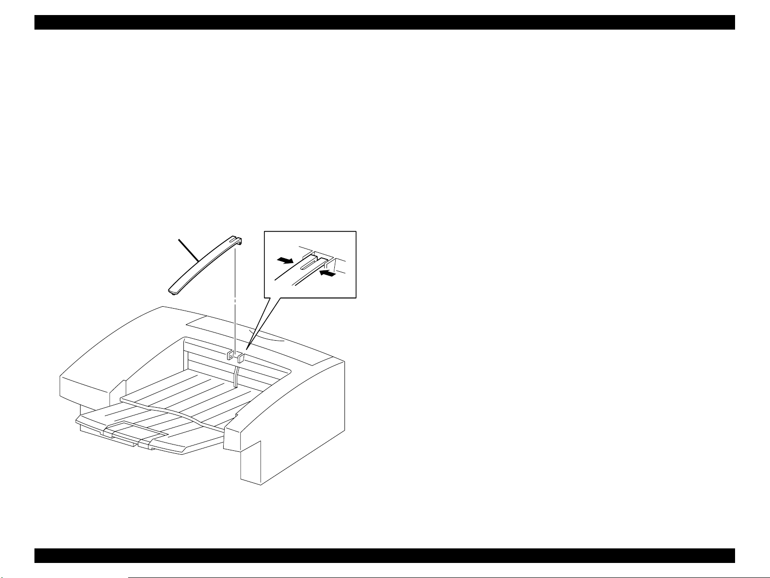
EPSON EPL-N2050 Optional Units Revision B
3.2.7 Link Weight
3.2.7.1 Removal
1. Deflecting the left and right brackets of Link Weight, draw the shaft from
the bearing bore of the Cover OCT, and remove the Link Weight from the
Shifter.
3.2.7.2 Assembly
1. Deflecting the left and right brackets of Link Weight, insert the shaft into
the bearing bore of the Cover OCT, and mount the Link Weight on the
Shifter.
Link Weight
Figure 3-6. Link Weight Removal
Shifter Introduction 77
Page 78

EPSON EPL-N2050 Optional Units Revision B
3.2.8 Cover Rear
3.2.8.1 Removal
1. Open the Cover Rear from the Shifter.
2. Deflecting the right bracket of Cover Rear with a small screwdriver, draw
the shaft from the right hole in the Cover OCT.
3. Draw the left chaff of Cover Rear from the left hole in the Cover OCT, and
remove the Cover Rear.
3.2.8.2 Assembly
1. Insert the left shaft of Cover Rear into the left hole in the Cover OCT.
2. Deflecting the right bracket of Cover Rear with a small screwdriver,
engage the boss with the right hole in the Cover OCT.
3. Close the Cover Rear from the Shifter.
Figure 3-7. Cover Rear Removal
Shifter Introduction 78
Page 79

EPSON EPL-N2050 Optional Units Revision B
3.2.9 Chute Exit Inner Assy
3.2.9.1 Removal
1. Remove the Link Weight. (See “Link Weight” on page 77.)
2. Remove the Tray Exit Assy. (See “Tray Exit Assy” on page 74.)
3. Remove the Tray Exit. (See “Tray Exit” on page 76.)
4. Remove the Spring Tray. (See “Spring Tray” on page 75.)
5. Open the Cover Rear.
6. Remove the Cover Lower. (See “Cover Lower” on page80.)
7. Remove the five screws securing the Chute Exit Inner Assy to the Shifter.
8. Remove the Chute Exit Inner Assy from the Shifter.
3.2.9.2 Assembly
1. Align the Chute Exit Inner Assy with its mount position on the Shifter.
2. Secure the Chute Exit Inner Assy to the Shifter with five screws.
3. Mount the Cover Lower.
4. Close the Cover Rear.
5. Mount the Spring Tray.
6. Mount the Tray Exit.
7. Mount the Tray Exit Assy.
8. Mount the Link Weight.
Figure 3-8. Chute Exit Inner Assy Removal
Shifter Introduction 79
Page 80

EPSON EPL-N2050 Optional Units Revision B
3.2.10 Cover Lower
3.2.10.1 Removal
NOTE: In the following steps, do not damage the Actuator Full Stack.
1. Remove the Link Weight. (See “Link Weight” on page 77.)
2. Remove the Tray Exit Assy. (See “Tray Exit Assy” on page 74.)
3. Remove the Tray Exit. (See “Tray Exit” on page 76.)
4. Remove the Spring Tray. (See “Spring Tray” on page 75.)
5. Open the Cover Rear.
6. Remove the six screws securing the Cover Lower to the Chute Exit Inner
Assy.
7. Remove the Cover Lower from the Chute Exit Inner Assy.
3.2.10.2 Assembly
NOTE: In the following steps, do not damage the Actuator Full Stack.
1. Align the Cover Lower with its mount position on the Chute Exit Inner
Assy.
2. Secure the Cover Lower to the Chute Exit Inner Assy with six screws.
3. Close the Cover Rear.
4. Mount the Spring Tray.
5. Mount the Tray Exit.
6. Mount the Tray Exit Assy.
7. Mount the Link Weight.
Figure 3-9. Cover Lower Removal
Shifter Introduction 80
Page 81

EPSON EPL-N2050 Optional Units Revision B
3.2.11 PWBA OCT
3.2.11.1 Removal
1. Remove the Link Weight. (See “Link Weight” on page 77.)
2. Remove the Tray Exit Assy. (See “Tray Exit Assy” on page 74.)
3. Remove the Tray Exit. (See “Tray Exit” on page 76.)
4. Remove the Spring Tray. (See “Spring Tray” on page 75.)
5. Open the Cover Rear.
6. Remove the Cover Lower. (See “Cover Lower” on page80.)
7. Remove the Chute Exit Inner Assy. (See “Chute Exit Inner Assy” on
page 79.)
8. Remove the one screw securing the PWBA OCT to the Chute Exit Inner
Assy.
NOTE: In the following steps, do not detach Chute Exit Inner Assy and
PWBA OCT far away because they are connected with the harness.
9. Detach the PWBA OCT a little from the Chute Exit Inner Assy.
10. Unplug the connector (P/J223) from the PWBA OCT.
11. Unplug the connector (P/J210) from the PWBA OCT.
8. Mount the Cover Lower.
9. Close the Cover Rear.
10. Mount the Spring Tray.
11. Mount the Tray Exit.
12. Mount the Tray Exit Assy.
13. Mount the Link Weight.
12. Unplug the connector (P/J224) from the PWBA OCT.
13. Unplug the connector (P/J209) from the PWBA OCT.
3.2.11.2 Assembly
1. Plug the connector (P/J209) to the PWBA OCT.
2. Plug the connector (P/J224) to the PWBA OCT.
3. Plug the connector (P/J210) to the PWBA OCT.
4. Plug the connector (P/J223) to the PWBA OCT.
5. Align the PWBA OCT with its mount position on the Chute Exit Inner Assy.
6. Secure the PWBA OCT to the Chute Exit Inner Assy with one screw.
7. Mount the Chute Exit Inner Assy.
Shifter Introduction 81
Figure 3-10. PWBA OCT Removal
Page 82

EPSON EPL-N2050 Optional Units Revision B
3.2.12 Motor Drive Assy
3.2.12.1 Removal
1. Remove the Link Weight. (See “Link Weight” on page 77.)
2. Remove the Tray Exit Assy. (See “Tray Exit Assy” on page 74.)
3. Remove the Tray Exit. (See “Tray Exit” on page 76.)
4. Remove the Spring Tray. (See “Spring Tray” on page 75.)
5. Open the Cover Rear.
6. Remove the Cover Lower. (See “Cover Lower” on page80.)
7. Remove the Chute Exit Inner Assy. (See “Chute Exit Inner Assy” on
page 79.)
8. Remove the two screws securing the Motor Drive Assy to the Chute Exit
Inner Assy.
NOTE: In the following steps, do not detach Chute Exit Inner Assy and
Motor Drive Assy far away they are connected with the harness.
9. Detach the Motor Drive Assy a little from the Chute Exit Inner Assy.
10. Unplug the connector (P/J210) of the Motor Drive Assy.
7. Close the Cover Rear.
8. Mount the Spring Tray.
9. Mount the Tray Exit.
10. Mount the Tray Exit Assy.
11. Mount the Link Weight.
3.2.12.2 Assembly
NOTE: The Motor Drive Assy must be mounted with its connector facing
the front.
1. Plug the connector (P/J210) of the Motor Drive Assy.
2. Positioning the lower hole in Motor Drive between Plate Earth and HSG
Gear, mount the Motor Drive Assy on the Chute Exit Inner Assy.
3. Secure the lower hole in the Motor Drive Assy to the Chute Exit Inner
Assy with one screw.
4. Secure the upper hole in Motor Drive Assy together with Wire Assy OCT
to the Chute Exit Inner Assy with one screw.
5. Mount the Chute Exit Inner Assy.
6. Mount the Cover Lower.
Shifter Introduction 82
Figure 3-11. Motor Drive Assy Removal
Page 83

EPSON EPL-N2050 Optional Units Revision B
3.2.13 Eliminator
3.2.13.1 Removal
1. Remove the Link Weight. (See “Link Weight” on page 77.)
2. Remove the Tray Exit Assy. (See “Tray Exit Assy” on page 74.)
3. Remove the Tray Exit. (See “Tray Exit” on page 76.)
4. Remove the Spring Tray. (See “Spring Tray” on page 75.)
5. Open the Cover Rear.
6. Remove the Cover Lower. (See “Cover Lower” on page80.)
7. Remove the Chute Exit Inner Assy. (See “Chute Exit Inner Assy” on
page 79.)
8. Remove the three screws securing the Eliminator from the Chute Exit
Inner Assy.
9. Remove the Eliminator from the Chute Exit Inner Assy.
3.2.13.2 Assembly
1. Align the Eliminator with its mount position on the Chute Exit Inner Assy.
2. Secure the left hole in Eliminator together with Wire Assy OCT to the
Chute Exit Inner Assy with one screw.
3. Secure the Eliminator to the Chute Exit Inner Assy with two screws.
Figure 3-12. Eliminator Removal
4. Mount the Chute Exit Inner Assy.
5. Mount the Cover Lower.
6. Close the Cover Rear.
7. Mount the Spring Tray.
8. Mount the Tray Exit.
9. Mount the Tray Exit Assy.
10. Mount the Link Weight.
Shifter Introduction 83
Page 84

EPSON EPL-N2050 Optional Units Revision B
3.2.14 Solenoid Direction
3.2.14.1 Removal
1. Remove the Link Weight. (See “Link Weight” on page 77.)
2. Remove the Tray Exit Assy. (See “Tray Exit Assy” on page 74.)
3. Remove the Tray Exit. (See “Tray Exit” on page 76.)
4. Remove the Spring Tray. (See “Spring Tray” on page 75.)
5. Open the Cover Rear.
6. Remove the Cover Lower. (See “Cover Lower” on page80.)
7. Remove the Chute Exit Inner Assy. (See “Cover Lower” on page 80.)
8. Unplug the connector (P/J228) from the Solenoid Direction.
NOTE: Take care not to drop the Solenoid Direction when remove the
screw.
9. Remove the two screws securing the Solenoid Direction to the Chute Exit
Inner Assy.
10. Unhook the harness of Solenoid Direction from the Chute Exit Inner Assy,
and remove the Solenoid Direction.
9. Mount the Tray Exit.
10. Mount the Tray Exit Assy.
11. Mount the Link Weight.
3.2.14.2 Assembly
1. Aligning the spool of Solenoid Direction with the notch in Lever Solenoid,
mount the Solenoid Direction on the Chute Exit Inner Assy.
2. Hook the harness of Solenoid Direction to the Chute Exit Inner Assy.
3. Secure the Solenoid Direction to the Chute Exit Inner Assy with two
screws.
4. Plug the connector (P/J228) of the Solenoid Direction.
5. Mount the Chute Exit Inner Assy.
6. Mount the Cover Lower.
7. Close the Cover Rear.
8. Mount the Spring Tray.
Shifter Introduction 84
Figure 3-13. Solenoid Direction Removal
Page 85

EPSON EPL-N2050 Optional Units Revision B
3.2.15 Sensor Assy Exit OCT
3.2.15.1 Removal
1. Remove the Link Weight. (See “Link Weight” on page 77.)
2. Remove the Tray Exit Assy. (See “Tray Exit Assy” on page 74.)
3. Remove the Tray Exit. (See “Tray Exit” on page 76.)
4. Remove the Spring Tray. (See “Spring Tray” on page 75.)
5. Open the Cover Rear.
6. Remove the Cover Lower. (See “Cover Lower” on page80.)
7. Remove the Chute Exit Inner Assy. (See “Chute Exit Inner Assy” on
page 79.)
8. Disengage four hooks that secure the Sensor Assy Exit OCT to the Chute
Exit Inner Assy.
9. Unplug the connector (P/J227) from the Sensor Assy Exit OCT.
3.2.15.2 Assembly
1. Plug the connector (P/J227) of the Sensor Assy Exit OCT.
2. Align the position exactly, secure the Sensor Assy Exit OCT to the Chute
Exit Inner Assy with four hooks.
3. Mount the Chute Exit Inner Assy.
4. Mount the Cover Lower.
5. Close the Cover Rear.
6. Mount the Spring Tray.
7. Mount the Tray Exit.
8. Mount the Tray Exit Assy.
9. Mount the Link Weight.
Figure 3-14. Sensor Assy Exit OCT Removal
Shifter Introduction 85
Page 86

EPSON EPL-N2050 Optional Units Revision B
3.2.16 Actuator Full Stack
3.2.16.1 Removal
1. Remove the Link Weight. (See “Link Weight” on page 77.)
2. Remove the Tray Exit Assy. (See “Tray Exit Assy” on page 74.)
3. Remove the Tray Exit. (See “Tray Exit” on page 76.)
4. Remove the Spring Tray. (See “Spring Tray” on page 75.)
5. Open the Cover Rear.
6. Remove the Cover Lower. (See “Cover Lower” on page80.)
7. Remove the Chute Exit Inner Assy. (See “Chute Exit Inner Assy” on
page 79.)
NOTE: In the following steps, do not damage the Actuator Full Stack.
8. Disengage the left shaft of Actuator full Stack from the left bearing of
Chute Exit Inner Assy.
9. Disengage the right shaft of Actuator full Stack from the right bearing of
Chute Exit Inner Assy, and remove the Actuator full Stack.
3.2.16.2 Assembly
9. Mount the Link Weight.
NOTE: In the following steps, do not damage the Actuator Full Stack.
1. Engage the right shaft of Actuator full Stack with the right bearing of
Chute Exit Inner Assy.
2. Engage the left shaft of Actuator full Stack with the left bearing of Chute
Exit Inner Assy.
3. Mount the Chute Exit Inner Assy.
4. Mount the Cover Lower.
5. Close the Cover Rear.
6. Mount the Spring Tray.
7. Mount the Tray Exit.
8. Mount the Tray Exit Assy.
Figure 3-15. Actuator Full Stack Removal
Shifter Introduction 86
Page 87

EPSON EPL-N2050 Optional Units Revision B
3.2.17 Sensor Full Stack
3.2.17.1 Removal
1. Remove the Link Weight. (See “Link Weight” on page 77.)
2. Remove the Tray Exit Assy. (See “Tray Exit Assy” on page 74.)
3. Remove the Tray Exit. (See “Tray Exit” on page 76.)
4. Remove the Spring Tray. (See “Spring Tray” on page 75.)
5. Open the Cover Rear.
6. Remove the Cover Lower. (See “Cover Lower” on page80.)
7. Remove the Chute Exit Inner Assy. (See “Chute Exit Inner Assy” on
page 79.)
8. Remove the PWBA OCT. (See “PWBA OCT” on page 81.)
9. Unplug the connector (P/J225) from the Sensor Full Stack.
10. Disengage four hooks that secure the Sensor Full Stack to the Chute Exit
Inner Assy.
11. Remove the Sensor Full Stack from the Chute Exit Inner Assy.
3.2.17.2 Assembly
1. Align the position exactly, secure the Sensor Full Stack to the Chute Exit
Inner Assy with four hooks.
Sensor Full Stack
Right
Left
2. Plug the connector (P/J225) to the Sensor Full Stack.
3. Mount the PWBA OCT.
4. Mount the Chute Exit Inner Assy.
5. Mount the Cover Lower.
6. Close the Cover Rear.
7. Mount the Spring Tray.
8. Mount the Tray Exit.
9. Mount the Tray Exit Assy.
10. Mount the Link Weight.
Figure 3-16. Sensor Full Stack Removal
Shifter Introduction 87
Page 88

EPSON EPL-N2050 Optional Units Revision B
3.2.18 Roll Assy Offset
3.2.18.1 Removal
1. Remove the Link Weight. (See “Link Weight” on page 77.)
2. Remove the Tray Exit Assy. (See “Tray Exit Assy” on page 74.)
3. Remove the Tray Exit. (See “Tray Exit” on page 76.)
4. Remove the Spring Tray.(See “Spring Tray” on page 75.)
5. Open the Cover Rear.
6. Remove the Cover Lower. (See “Cover Lower” on page80.)
7. Remove the Chute Exit Inner Assy. (See “Chute Exit Inner Assy” on
page 79.)
8. Remove the PWBA OCT. (See “PWBA OCT” on page 81.)
9. Remove the Offset Assy. (See “Offset Assy” on page 93.)
10. Remove the Eliminator. (See “Elimin ator” on page 83.)
11. Remove the Actuator Full Stack. (See “Actuator Full Stack” on page 86.)
12. Unhook the Gear Exit OCT from the left shaft of Shaft Exit, and remove
the Gear Exit OCT from the Chute Exit Inner Assy.
13. Remove the Bearin g Exit from th e l e ft sh a f t o f Shaft Exit of the Chute Exit
Inner Assy.
3. Secure the left shaft of Shaft Exit to the Chute Exit Inner Assy with the
Bearing Exit.
4. Hook the Gear Exit OCT to the left shaft of Shaft Exit to mount the Gear
Exit OCT on the Chute Exit Inner Assy.
5. Mount the Actuator Full Stack.
6. Mount the Eliminator.
7. Mount the Offset Assy.
8. Mount the PWBA OCT.
9. Mount the Chute Exit Inner Assy.
10. Mount the Cover Lower.
11. Close the Cover Rear.
12. Mount the Spring Tray.
13. Mount the Tray Exit Ç.
14. Mount the Tray Exit Assy.
15. Mount the Link Weight.
14. Disengage the hole in Lever Offset from the hook of Roll Assy Offset.
15. Remove the Shaft Exit securing the Roll Assy Offset together with Bearing
Exit and E-ring from the right hole in the Chute Exit Inner Assy.
16. Remove the Roll Assy Offset fr om the Chute Exit Inner Assy.
3.2.18.2 Assembly
1. Insert two bosses at the bottom of Roll Assy Offset into a gap between
Holder PWBA OCT and HSG Gear, and mount the Roll Assy Offset on the
Chute Exit Inner Assy.
2. From the right hole in the Chute Exit Inner Assy, insert the Shaft Exit into
the hole in the Roll Assy Offset to secure the Roll Assy Offset to the Chute
Exit Inner Assy.
Shifter Introduction 88
Page 89

EPSON EPL-N2050 Optional Units Revision B
Figure 3-17. Roll Assy Offset Removal
Shifter Introduction 89
Page 90

EPSON EPL-N2050 Optional Units Revision B
3.2.19 Roll Assy MID OCT
3.2.19.1 Removal
1. Remove the Link Weight. (See “Link Weight” on page 77.)
2. Remove the Tray Exit Assy. (See “Tray Exit Assy” on page 74.)
3. Remove the Tray Exit. (See “Tray Exit” on page 76.)
4. Remove the Spring Tray. (See “Spring Tray” on page 75.)
5. Open the Cover Rear.
6. Remove the Cover Lower. (See “Cover Lower” on page80.)
7. Remove the Chute Exit Inner Assy. (See “Chute Exit Inner Assy” on
page 79.)
8. Remove the PWBA OCT. (See “PWBA OCT” on page 81.)
9. Remove the one screw securing the Plate Earth to the Chute Exit Inner
Assy.
10. Remove the three screws securing the Holder PWBA to the Chute Exit
Inner Assy.
11. Remove the Holder together with Harness Assy OCT and Plate Earth from
the Chute Exit Inner Assy.
12. Unhook the Gear Exit from the left shaft of Roll Assy MID OCT, and
remove the Gear Exit from the Chute Exit Inner Assy.
13. Disengage the right E-ring that secures the Roll Assy MID OCT to the
Chute Exit Inner Assy.
14. Remove the Bearing Exit that secures the left and right shafts of Roll Assy
MID OCT to the Chute Exit Inner Assy.
3.2.19.2 Assembly
1. Insert the left shaft Roll Assy MID OCT into the left hole in the Chute Exit
Inner Assy.
2. Insert the right shaft of Roll Assy MID OCT into the right hole in the Chute
Exit Inner Assy.
3. Secure the left and right shafts of Roll Assy MID OCT to the Chute Exit
Inner Assy with the Bearing Exit.
4. Secure the right shaft of Roll Assy MID OCT to the Chute Exit Inner Assy
with an E-ring.
5. Hook the Gear Exit to the left shaft of Roll Assy MID OCT to mount the
Gear Exit on the Chute Exit Inner Assy.
6. Aligning the position exactly, mount the Holder PWBA together with
Harness Assy OCT and Plate Earth Chute Exit Inner Assy.
7. Secure the Holder PWBA to the Chute Exit Inner Assy with three screws.
8. Secure the Plate Earth to the Chute Exit Inner Assy with one screw.
9. Mount the PWBA OCT.
10. Mount the Chute Exit Inner Assy.
11. Mount the Cover Lower.
12. Close the Cover Rear.
13. Mount the Spring Tray.
14. Mount the Tray Exit.
15. Mount the Tray Exit Assy.
16. Mount the Link Weight.
15. Shifting the Roll Assy MID OCT to the left fro m th e Chute Exit Inner Assy,
draw the right shaft from the right hole in the Chute Exit Inner Assy.
16. Draw the Roll Assy MID OCT from the Chute Exit Inner Assy.
Shifter Introduction 90
Page 91

EPSON EPL-N2050 Optional Units Revision B
Right
Figure 3-18.
Roll Assy MID OCT Removal (1)
Figure 3-20.
Roll Assy MID OCT Removal (3)
Figure 3-19.
Roll Assy MID OCT Removal (2)
Shifter Introduction 91
Page 92

EPSON EPL-N2050 Optional Units Revision B
3.2.20 Chute Exit Inner
3.2.20.1 Removal
1. Remove the four screws securing the Chute Exit Inner to Chute Exit Inner
Assy.
2. Remove the Chute Exit Inner from Chute Exit Inner Assy.
3.2.20.2 Assembly
1. Align the Chute Exit Inner with its mount position on the Chute Exit Inner
Assy.
2. Secure the Chute Exit Inner to the Chute Exit Inner Assy with four screws.
Figure 3-21. Chute Exit Inner Removal
Shifter Introduction 92
Page 93

EPSON EPL-N2050 Optional Units Revision B
3.2.21 Offset Assy
3.2.21.1 Removal
1. Remove the Link Weight. (See “Link Weight” on page 77.)
2. Remove the Tray Exit Assy. (See “Tray Exit Assy” on page 74.)
3. Remove the Tray Exit. (See “Tray Exit” on page 76.)
4. Remove the Spring Tray. (See “Spring Tray” on page 75.)
5. Open the Cover Rear.
6. Remove the Cover Lower. (See “Cover Lower” on page80.)
7. Remove the Chute Exit Inner Assy. (See “Chute Exit Inner Assy” on
page 79.)
8. Unhook the Lever Offset of Offset Assy from the Chute Exit Inner Assy.
9. Remove the two screws securing the Offset Assy to the Chute Exit Inner
Assy.
NOTE: In the following steps, do not detach Chute Exit Inner Assy and
Offset Assy far away they are connected with the harness.
10. Detach the Offset Assy a little from the Chute Exit Inner Assy.
11. Unplug the connector (P/J226) from the Sensor OCT Home.
4. Align the Offset Assy with its mount position to the Chute Exit Inner Assy.
5. Secure the Offset Assy to the Chute Exit Inner Assy with two screws.
6. Engaging the hole in the Lever Offset of Offset Assy with the hook of
Chute Exit Inner Assy, secure the Lever Offset with the hook.
7. Mount the Chute Exit Inner Assy.
8. Mount the Cover Lower.
9. Close the Cover Rear.
10. Mount the Spring Tray.
11. Mount the Tray Exit.
12. Mount the Tray Exit Assy.
13. Mount the Link Weight.
12. Unplug the connector (P/J210) of the Motor Offset Assy.
13. Unclamp the harness of Motor Offset Assy at two places from the Chute
Exit Inner Assy.
14. Remove the Offset Assy from the Chute Exit Inner Assy.
15.
3.2.21.2 Assembly
1. Plug the connector (P/J210) of the Motor Offset Assy.
2. Plug the connector (P/J226) from the Sensor OCT Home.
3. Clamp the harness of Motor Offset Assy at two places to the Chute Exit
Inner Assy.
Shifter Introduction 93
Page 94

EPSON EPL-N2050 Optional Units Revision B
Figure 3-22. Offset Assy Removal
Shifter Introduction 94
Page 95

EPSON EPL-N2050 Optional Units Revision B
3.2.22 Motor Offset Assy
3.2.22.1 Removal
1. Remove the Link Weight. (See “Link Weight” on page 77.)
2. Remove the Tray Exit Assy. (See “Tray Exit Assy” on page 74.)
3. Remove the Tray Exit. (See “Tray Exit” on page 76.)
4. Remove the Spring Tray. (See “Spring Tray” on page 75.)
5. Open the Cover Rear.
6. Remove the Cover Lower. (See “Cover Lower” on page80.)
7. Remove the Chute Exit Inner Assy. (See “Chute Exit Inner Assy” on
page 79.)
8. Remove the Offset Assy. (See “Offset Assy” on page 93.)
9. Remove the two screws securing the Motor Offset Assy to the Offset
Assy.
10. Remove the Motor Offset Assy from the Offset Assy.
3.2.22.2 Assembly
1. Align the Motor Offset Assy with its mount position to the Offset Assy.
10. Mount the Link Weight.
2. Secure the Motor Offset Assy to the Offset Assy with two screws.
3. Mount the Offset Assy .
4. Mount the Chute Exit Inner Assy.
5. Mount the Cover Lower.
6. Close the Cover Rear.
7. Mount the Spring Tray.
8. Mount the Tray Exit.
9. Mount the Tray Exit Assy.
Figure 3-23. Motor Offset Assy Removal
Shifter Introduction 95
Page 96

EPSON EPL-N2050 Optional Units Revision B
3.2.23 Sensor OCT Home
3.2.23.1 Removal
1. Remove the Link Weight. (See “Link Weight” on page 77.)
2. Remove the Tray Exit Assy. (See “Tray Exit Assy” on page 74.)
3. Remove the Tray Exit. (See “Tray Exit” on page 76.)
4. Remove the Spring Tray. (See “Spring Tray” on page 75.)
5. Open the Cover Rear.
6. Remove the Cover Lower. (See “Cover Lower” on page80.)
7. Remove the Chute Exit Inner Assy. (See “Chute Exit Inner Assy” on
page 79.)
8. Remove the Offset Assy. (See “Offset Assy” on page 93.)
9. Disengage the five hooks that secure the Sensor OCT Home to the Offset
Assy.
10. Remove the Sensor OCT Home from the Offset Assy.
3.2.23.2 Assembly
1. Align the Sensor OCT Home with its mount position to the Offset Assy.
2. Secure the five hooks the Sensor OCT Home to the Offset Assy.
3. Mount the Offset Assy .
4. Mount the Chute Exit Inner Assy.
5. Mount the Cover Lower.
6. Close the Cover Rear.
7. Mount the Spring Tray.
8. Mount the Tray Exit.
9. Mount the Tray Exit Assy.
10. Mount the Link Weight.
Shifter Introduction 96
Figure 3-24. Sensor OCT Home Removal
Page 97

EPSON EPL-N2050 Optional Units Revision B
3.3 Parts List and Exploded Diagram
Table 3-1. Parts List
Ref No. Part Code Description
S64.1.2 1051668 TRAY EXIT ASSY
S64.1.4 1051669 TRAY EXIT
S64.1.6 1051670 LINK WEIGHT
S64.1.7 1051671 COVER REAR
H1.1.11 1051672 COVER OCT
H1.1.14 1051673 COVER LOWER
H1.2.1 2033502 CHUTE EXIT INNER ASSY
H1.2.2 2033750 HARNESS ASSY UNIT
H1.2.3 1052064 HOLDER PWBA
H1.2.4 2033503 PWBA OCT
H1.2.6 2033504 MOTOR DRIVE ASSY
H1.2.13 1052066 ELIMINATOR
H1.2.15 2033505 SOLENOID DIRECTION
H1.2.16 1051674 LEVER SOLENOID
H1.2.18 2033506 SENSOR ASSY EXIT OCT
H1.2.19 1051675 ACUTUATOR FULL STACK
H1.2.20 2021773 E.R.M. SENSOR
H1.2.21 2033751 HARNESS ASSY OCT SNR
1.2.32 1051676 CHUTE EXIT INNER
1.2.34 2033507 OFFSET ASSY
1.2.35 2033752 MOTOR SFFSET ASSY
1.2.37 2021773 E.R.M. SENSOR
Shifter Parts List and Exploded Diagram 97
Page 98

The parts to which no reference number
is assigned will not be available as
after-sale service parts.
EPSON EPL-N2050 Optional Units Revision B
Shifter (1.1)
10168 Rev.01
Figure 3-25. Exploded Diagram (1)
.
.
Shifter Parts List and Exploded Diagram 98
Page 99

(in clide Fig 1.2)
The parts to which no reference number
is assigned will not be available as
after-sale service parts.
EPSON EPL-N2050 Optional Units Revision B
Figure 3-26. Exploded Diagram (2)
Shifter (1.2)
10168 Rev.01
Shifter Parts List and Exploded Diagram 99
Page 100

ENVELOPE FEEDER
CHAPTER
4
 Loading...