

Page 1
®
EPSON EPL-N1600 Option
Duplex Unit
Page 2

Notice
g
g
g
g
g
g
g
EPSON is a re
General Notice: Other product names used herein are for identification purpose only and may be trademarks or registered trademar ks of their
Copyright © 1998 SEIKO EPSON CORPORATION. Printed in Japan.
hts reserved. No part of t his manual may be r eprod uced, st ored in a r etri eval sy ste m, or t ransmit ted in any for m or by an y means el ectroni c,
All ri
mechanical, photocopyin
All effort have been made to ensure the accuracy of the contents of this manual. However, should any errors be detected, SEIKO EPSON would
reatly appreciate being informed of them.
The contents of this manual are subject to chan
All effort have been made to ensure the accuracy of the contents of this manual. However, should any errors be detected, SEIKO EPSON would
reatly appreciate being informed of them.
The above not withstandin
thereof.
istered trademark of SEIKO EPSON CORPORATION.
respective owners. EPSON disclaims any and all rights in those marks.
, or otherwise, without the prior written permission of SEIKO EPSON CORPORATION.
e without notice.
SEIKO EPSON CORPORATION can assume no responsibility for any errors in this manual or the consequences
Page 3

PRECAUTIONS
g
g
Precautionary notations throughout the text are categorized relative to 1)Personal injury and 2) damage to equipment.
DANGER
WARNING
The precautionary measures itemized below should always be observed when performin
Signals a precaution which, if ignored, could result in serious or fatal personal injury. Great caution should be exercised in
performin
Signals a precaution which, if ignored, could result in damage to equipment.
procedures preceded by DANGER Headings.
repair/maintenance procedures.
DANGER
1. ALWAYS DISCONNECT THE PRODUCT FROM THE POWER SOURCE AND PERIPHERAL DEVICES PERFORMING ANY
MAINTENANCE OR REPAIR PROCEDURES.
2. NO WORK SHOULD BE PERFORMED ON THE UNIT BY PERSONS UNFAMILIAR WITH BASIC SAFETY MEASURES AS DICTATED
FOR ALL ELECTRONICS TECHNICIANS IN THEIR LINE OF WORK.
3. WHEN PERFORMING TESTING AS DICTATED WITHIN THIS MANUAL, DO NOT CONNECT THE UNIT TO A POWER SOURCE UNTIL
INSTRUCTED TO DO SO. WHEN THE POWER SUPPLY CABLE MUST BE CONNECTED, USE EXTREME CAUTION IN WORKING ON
POWER SUPPLY AND OTHER ELECTRONIC COMPONENTS.
WARNING
1. REPAIRS ON EPSON PRODUCT SHOULD BE PERFORMED ONLY BY AN EPSON CERTIFIED REPAIR TECHNICIAN.
2. MAKE CERTAIN THAT THE SOURCE VOLTAGES IS THE SAME AS THE RATED VOLTAGE, LISTED ON THE SERIAL NUMBER/
RATING PLATE. IF THE EPSON PRODUCT HAS A PRIMARY AC RATING DIFFERENT FROM AVAILABLE POWER SOURCE, DO NOT
CONNECT IT TO THE POWER SOURCE.
3. ALWAYS VERIFY THAT THE EPSON PRODUCT HAS BEEN DISCONNECTED FROM THE POWER SOURCE BEFORE REMOVING OR
REPLACING PRINTED CIRCUIT BOARDS AND/OR INDIVIDUAL CHIPS.
4. IN ORDER TO PROTECT SENSITIVE MICROPROCESSORS AND CIRCUITRY, USE STATIC DISCHARGE EQUIPMENT, SUCH AS
ANTI-STATIC WRIST STRAPS, WHEN ACCESSING INTERNAL COMPONENTS.
5. REPLACE MALFUNCTIONING COMPONENTS ONLY WITH THOSE COMPONENTS BY THE MANUFACTURE; INTRODUCTION OF
SECOND-SOURCE ICs OR OTHER NONAPPROVED COMPONENTS MAY DAMAGE THE PRODUCT AND VOID ANY APPLICABLE
1. EPSON WARRANTY.
Page 4

About This Manual
g
g
g
g
g
g
g
g
g
g
g
g
g
g
g
g
g
This manual describes basi c functions, theory of electrical and mechanical operations, maintenance and repair procedures of the Duplex Unit for the
EPL-N1600. The instructions and procedures included herein are intended for the experienced repair technicians, and attention should be
the precautions on the precedin
page.
iven to
Contents
This manual consists of six chapters and Appendix.
CHAPTER 1. PRODUCT DESCRIPTIONS
Provides a
product.
CHAPTER 2. OPERATING PRINCIPLES
Describes the theory of electrical and mechanical
operations of the product.
CHAPTER 3. TROUBLESHOOTING
Provides the step-by-step procedures for
troubleshootin
CHAPTER 4. DISASSEMBLY AND ASSEMBLY
Describes the step-by-step procedures for
disassemblin
CHAPTER 5. ADJUSTMENTS
Provides Epson-approved methods for adjustment.
CHAPTER 6. MAINTENANCE
Provides preventive maintenance procedures and the
lists of Epson-approved lubricants and adhesives
required for servicin
APPENDIX
Provides the followin
reference:
• Connector pin assi
• Electric circuit boards components layout
• Exploded dia
• Electrical circuit boards schematics
eneral overview and specifications of the
.
and assembling the product.
the product.
additional information for
nments
ram
Symbols Used in This Manual
Various symbols are used throughout this manual either to provide
additional information on a specif ic topic or to warn of possible dan
present durin
they are used, and always read WARNING, CAUTION or NOTE
CHECK
PO IN T
es.
messa
W ARNING
CAUTION
a procedure or an action. Be aware of all symbols when
Indicates an operatin
or condition that, if not strictly observed, could result in
injury or loss of life.
Indicates an operatin
or condition that, if not strictly observed, could result in
dama
May indicate an operatin
practice or condition that is necessary to accomplish a task
efficiently. It may also provide additional information that is
related to a specific subject, or comment on the resul ts
achieved throu
e to, or destruction of, equipment.
h a previous action.
or maintenance procedure, practice
or maintenance procedure, practi ce,
or maintenance procedure,
er
Page 5

Revision Status
Revision Issued Date Description
Rev. 0 August 17, 1998 Prelimina ry release. (intended for service training purpose only)
Rev.A October 30, 1998 First release.
Page 6

EPSON EPL-N1600
g
g
g
Table of Contents
Product Descriptions
OVERVIEW ..................................... ...... ....... ...... ....... ...... ............................... 9
Basic specificatio n ........................ ...... ....................................... ..... 9
Paper specification.......................................................................... 9
Reliability/Durability/s ervicea bil it y ................................. ....... ...... ..... 9
dimension and wei
ht...... ...... ......................................................... 9
Operating Principles
OVERVIEW .................................................................................................. 11
Paper Transportation............................................................................... 11
paper transportation control.......................................................... 13
Scannin
Drive Power Transmission ...................................................................... 14
Duplex unit drive power transmission (1)...................................... 15
Duplex unit drive power transmission (2)...................................... 15
Function of Duplex Unit Major Components............................................ 16
Vertical Unit ........ ...... ....... ...... ....... ...... ....... ...... ....... ...... ................ 16
Horizontal Unit .............................................................................. 18
direction in duplex printing............................................ 13
Troubleshooting
Chute Cover............................................................................................ 27
Fan Assembly Duplex ............................................................................. 28
Sensor Assembly (Vertical)..................................................................... 29
Motor Duplex........................................................................................... 30
Solenoid .................................................................................................. 31
Shaft Latch & Lever................................................................................. 32
Rolls Pinch & Roll Assembly Exit............................................................ 33
Chute Lower & Roll Assembly................................................................. 34
Photo Interrupters (Rear I/L & Chute Cover I/L)..................................... 35
Photo Interrupter (PL11.1.9: Rear Interlock)................................. 35
Photo Interrupter (PL11.2.15: Chute Cover Interlock) .................. 35
Chute Upper............................................................................................ 36
Sensor Assembly (Horizontal)................................................................. 37
Roll Assembly #1 & Pinch Roll................................................................ 38
Plate Base............................................................................................... 39
Roll Assemblies #2 & #3 ......................................................................... 40
PWB Assembly Duplex ........................................................................... 41
Bracket & Gear Assembly ....................................................................... 42
Adjustment
Maintenance
DISASSEMBLY AND ASSEMBLY
OVERVIEW .................................................................................................. 23
Precautions ............................................................................................. 23
Tools........................................................................................................ 23
DISASSEMBLY AND ASSEMBLY............................................................... 24
Duplex Unit Removal............................................................................... 25
Duplex Assembly Unit Vertical................................................................ 26
Appendix
Connector Location ...................................................................................... 49
Exploded Dia
ram........................................................................................ 50
Duplex Unit (Optional)................................................................... 50
Duplex Unit Vertical I .................................................................... 52
Duplex Unit Vertical II ................................................................... 54
Duplex Unit Vertical III .................................................................. 56
Rev. 0 6
Page 7

EPSON EPL-N1600
Duplex Unit Horizontal I ................................................................ 58
Duplex Unit Horizontal II ............................................................... 60
Duplex Unit Chute......................................................................... 62
Rev. 0 7
Page 8

PRODUCT DESCRIPTIONS
Page 9

EPSON EPL-N1600/Duplex Unit Chapter 1 Product Descriptions
g
g
g
g
g
g
g
g
1.1 OVERVIEW
This section describes the specification of the 500 Sheets feeder.
BASIC SPECIFICATION
Paper Handlin
Drive Source: Driven by the base printer
Speed: A4 = 7.8PPM / Letter = 8.0PPM
Capacity: 1 sheet (in reverse tray)
Paper Feed Ori
PAPER SPECIFICATION
Paper Type: <Standard Paper>
: Tray reverse
in: Left edge of sheet
Xerox 4024DP 20 lb. (75
<Normal Paper>
60 - 105
- PPC Paper
- Bond paper
- Recycled paper
/m2 (16 - 28 lbs.)
/m2) paper
RELIABILITY/DURABILITY/SERVICEABILITY
MPBF: 25,000 sheets or more
MTBF: 3,000 hours or more
Life: 300,000 sheets or 5 years
(whichever comes first)
Paper Feed Reliability *1:<Jam rate>
1/2000 sheets or less
<Misfeed>
1/2000 sheets or less
<Multiple sheet feed>
1/500 sheets or less
<Folded coners>
1C or more at 1/1000 sheets or less
(1C or less is not included)
NOTE:
*1:With recommended paper and normal conditions
MTTR: 30 minutes or less
DIMENSION AND WEIGHT
Paper Size: A4 (210 x 297mm)
Letter (8.5 x 11 inch)
G-Le
Le
al (8.5 x 13 inch)
al (8.5 x 14 inch)
Dimension: 396 x 517 x 254 mm (W x D x H)
Wei
ht: 6.5 K
Rev. 0 9
Page 10

OPERATING PRINCIPLES
Page 11
EPSON EPL-N1600/Duplex Unit Chapter 2 Operating Principles
g
g
g
g
2.1 OVERVIEW
This section describes the operating principles of the Duplex Unit.
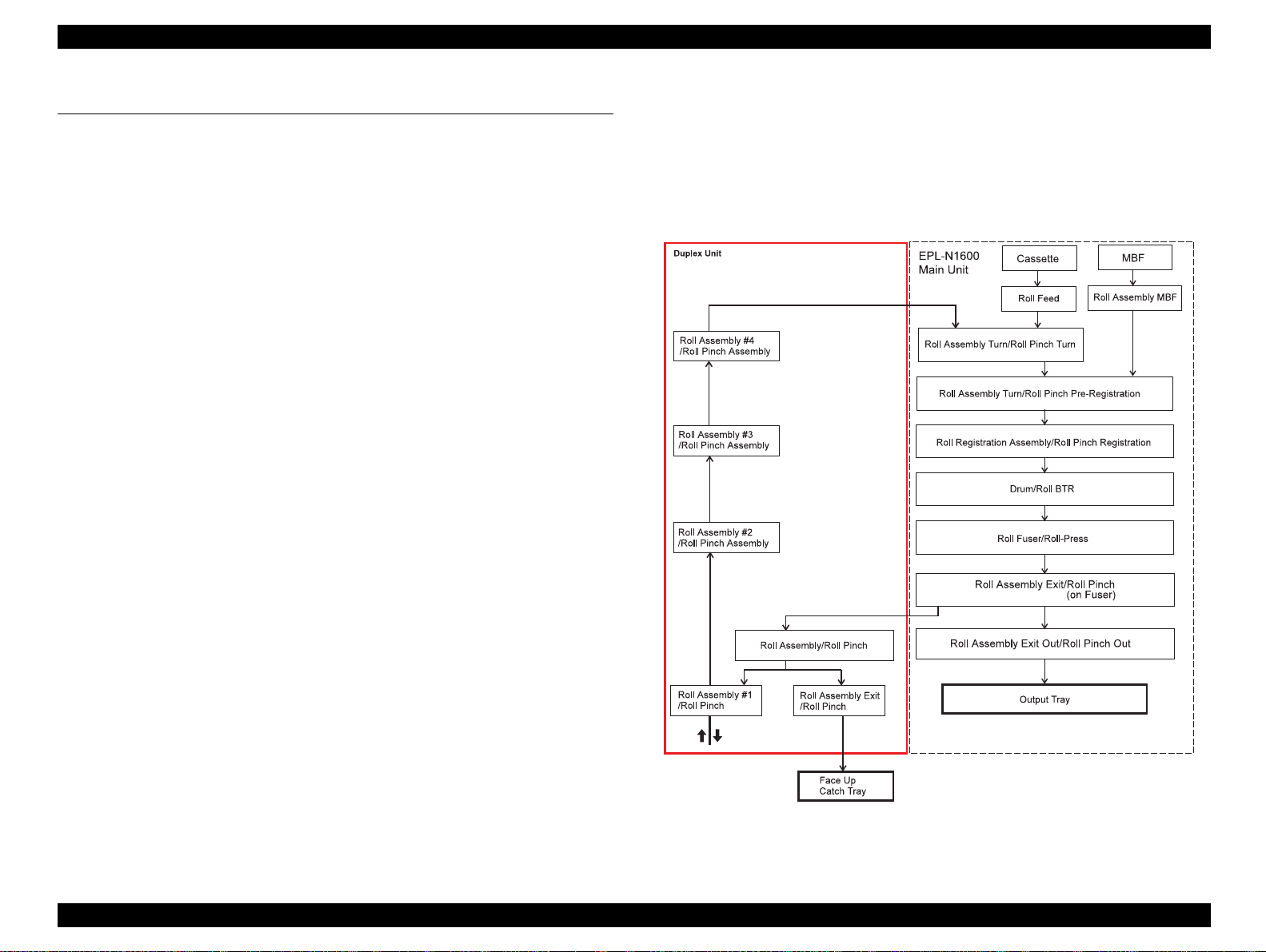
2.1.1 Paper Transportation
Paper is transported through the printer Base Engine and the Duplex
Unit alon
Mode is selected or the optional Face UP Catch Tray is installed and
selected. In the Duplex Mode, a sheet of paper printed on one side is
uided into the Duplex Unit to re-feed, turned over in the Duplex Unit,
reversed, and fed a
Catch Tray is selected, a sheet print ed on one side in the Simplex Mode
or a sheet printed on both sides is delivered into the Face Up Catch
Tray throu
the paper path shown in the Figure below when the Duplex
ain into the Base Engine. When the optional Offset
h the Duplex Unit.
Figure 2-1. Paper Transport Path
Rev. 0 11
Page 12
EPSON EPL-N1600/Duplex Unit Chapter 2 Operating Principles
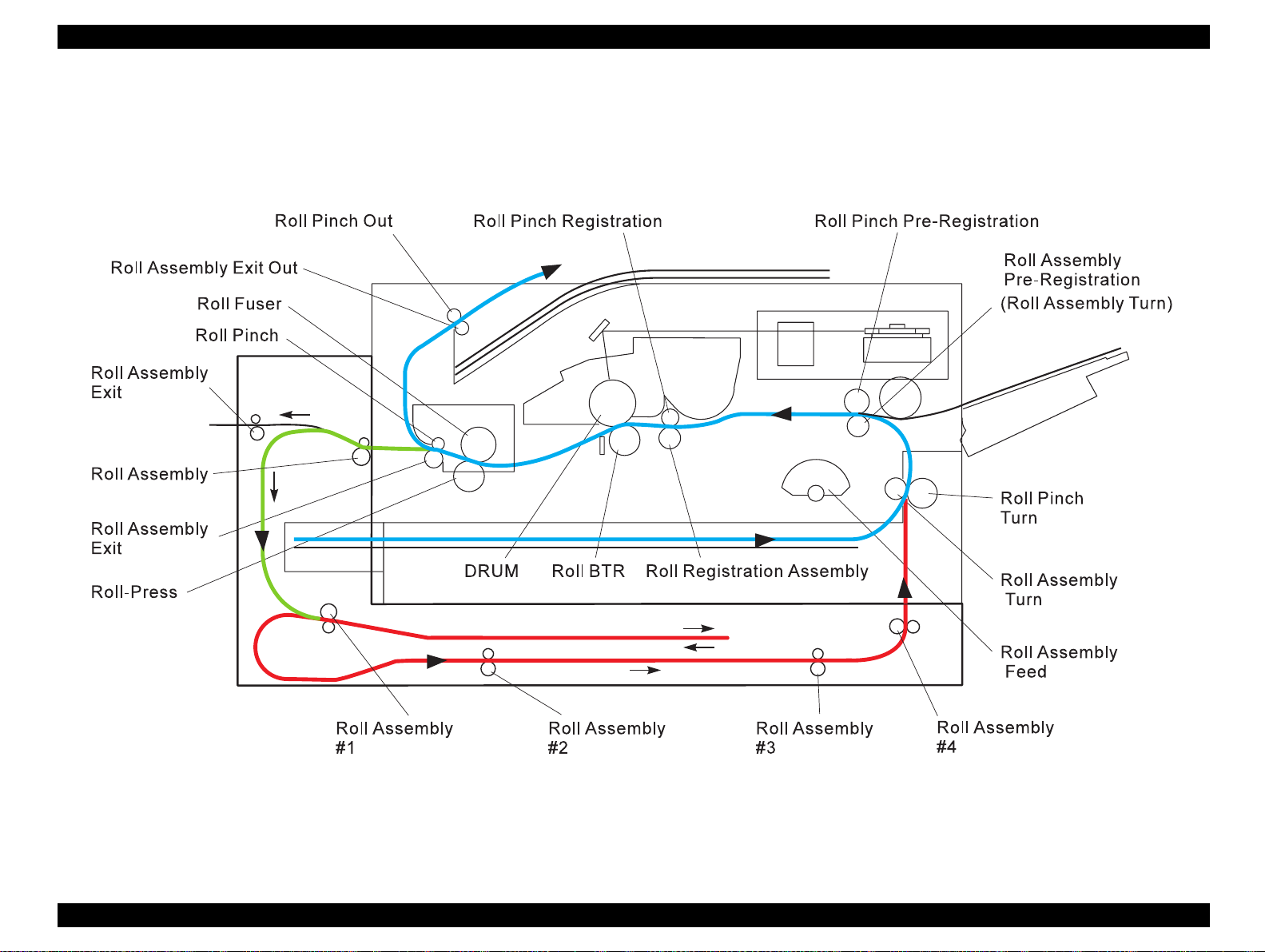
The Figure below is a cut-section side view of the EPL-N1600 with the
optional Duplex Unit attached that shows the paper path and the major
components directly related to the paper transportation.
Figure 2-2. Duplex Printing Paper Path
Rev. 0 12
Page 13
EPSON EPL-N1600/Duplex Unit Chapter 2 Operating Principles
g
g
g
g
g
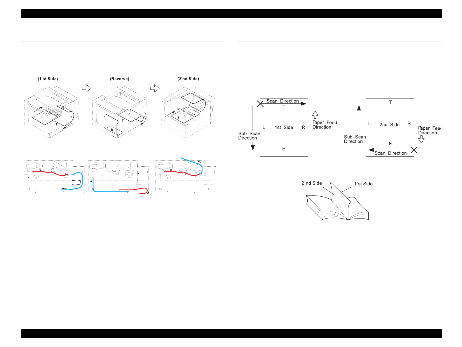
PAPER TRANSPORTATION CONTROL
The fi
ure below shows the paper movements in duplex printing mode.
SCANNING DIRECTION IN DUPLEX PRINTING
The fi
scannin
controller sends the ima
order of pa
ure below shows the relationship between the main and sub
direction and a side of the page printed in duplex pri nting. The
e data to the engine according to the printing
es, lines (raster lin es) on each page and pixels on each line.
Figure 2-3. Paper Movement Control
Figure 2-4. Scanning Direction
Rev. 0 13
Page 14
EPSON EPL-N1600/Duplex Unit Chapter 2 Operating Principles
g
g
g
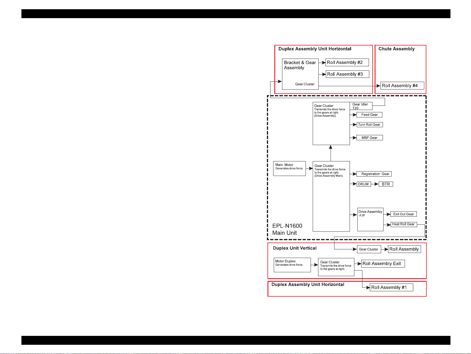
2.1.2 Drive Power Transmission
The Duplex Unit is operated by the drive power generated by the Main
Motor and the Paper Handlin
drive power
ure in right shows the relations of each components.
fi
enerated by the Motor Duplex within t he Duplex Unit. The
Motor of the Base Engine and by the
Figure 2-5. Drive Power Transmission
Rev. 0 14
Page 15
EPSON EPL-N1600/Duplex Unit Chapter 2 Operating Principles
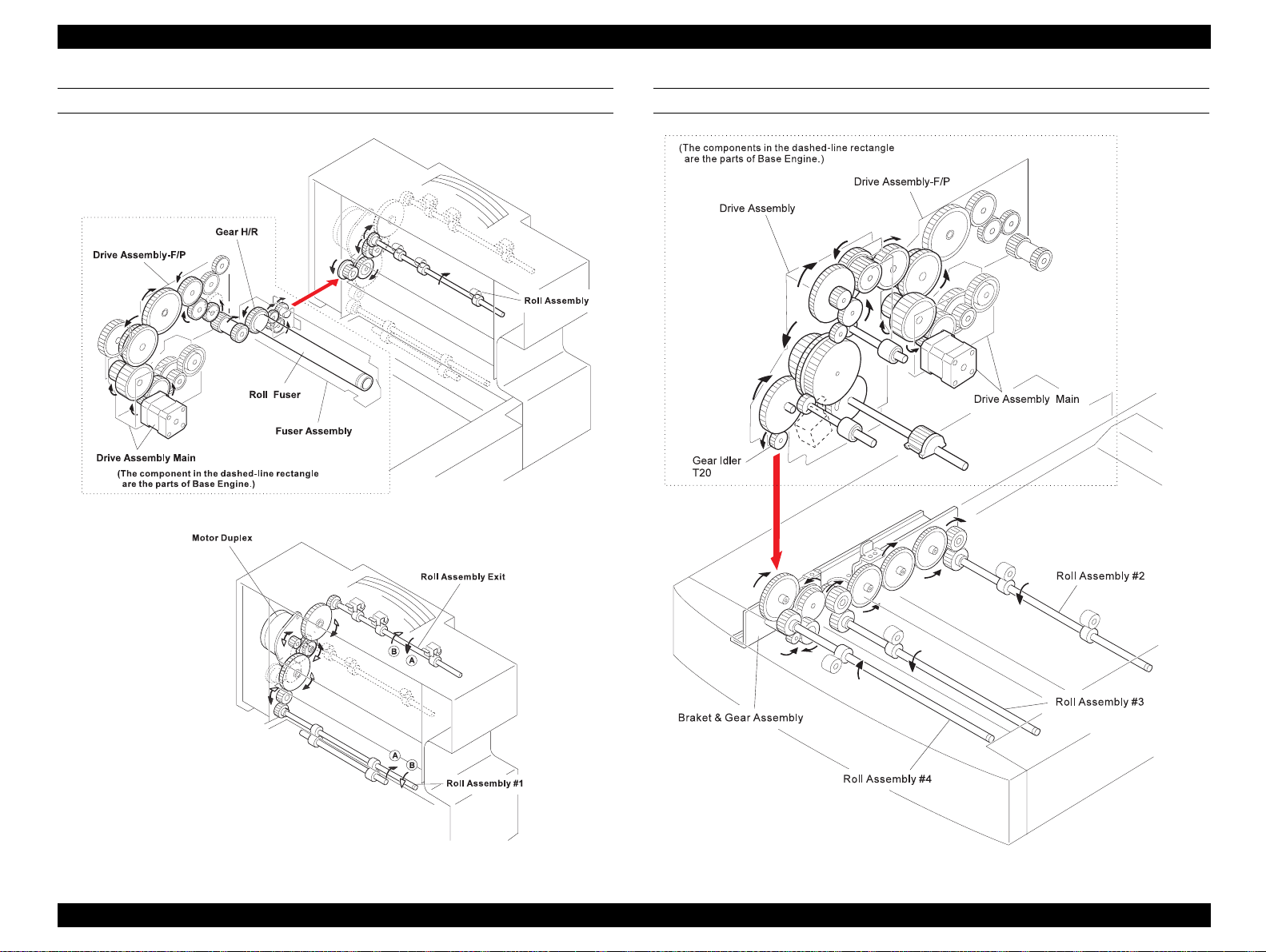
DUPLEX UNIT DRIVE POWER TRANSMISSION (1) DUPLEX UNIT DRIVE POWER TRANSMISSION (2)
Rev. 0 15
Page 16
EPSON EPL-N1600/Duplex Unit Chapter 2 Operating Principles
gag
gag
g
g
g
g
gg
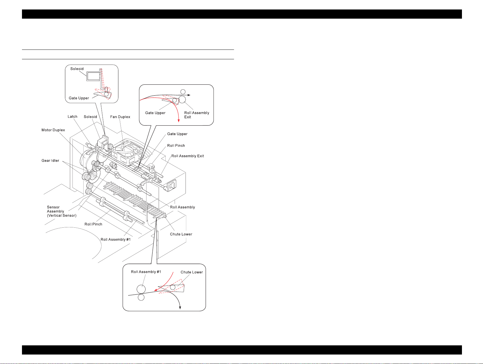
2.1.3 Function of Duplex Unit Major Components
VERTICAL UNIT
Motor Duplex: Generates the drive power for the Duplex
Unit.
Gear Cluster: Transmits the drive power from the Motor
Duplex to the Roll Assembly Exit and to Roll
Assembly #1 (part of the Horizontal Unit).
When the Vertical Unit is in place, the Idle r
Gear in the Gear Cluster en
the end of the Roll Assembly #1 shaft, and
transmits the drive power to Roll Assembly
#1. When the Vertical Unit is tilted back, the
Idler Gear disen
Roll Assembly #1 shaft.
Roll Assembly: Works with Rolls Pinch to drive paper from
the Fuser Exit Roll Assembly into the Vertical
Unit. The drive power is transmitted from the
Base En
the Duplex Gear Assembly of the Base
En
Roll Assembly Exit: Works with Rolls Pinch to drive paper out into
the Face Up Catch Tray. The drive power for
the Roll Assembly Exit is trans mitted fr om the
Motor Duplex throu
ine to the Roll Assembly, through
ine and the gears in the Duplex Unit.
e from the gear on the
h the Gear Cluster.
es the gear on
Gate Upper: A movin
to either Roll Assembly #1 or to the Roll
Assembly Exit.
Solenoid: To
Figure 2-6. Duplex Unit - Vertical unit Components
baffle that switches the paper path
les the Gate Upper.
Rev. 0 16
Page 17

EPSON EPL-N1600/Duplex Unit Chapter 2 Operating Principles
g
g
g
g
g
g
g
Sensor Assembly: Sensor in the Vertical Unit which is located
near the inlet and det ects paper which enters
the Duplex Unit. This sensor i s also called the
Vertical Sensor.
Chute Lower: Pushed down by the paper comin
Gate Upper, allowin
to Roll Assembly #1. Without the wei
the paper pushin
its raised position. Then the sh eet of paper,
driven in the reverse direction by Roll
Assembly #1, is
the Gate Lower to Roll Assembly #2.
Fan Duplex: Expels the air inside the Duplex Unit (and the
printer throu
introduces fresh air into the Duplex Unit and
the printer) to prevent an excessive r ise of the
inside temperature.
Latch: Secures the Vertical Unit to the rear of the
Base En
h the rear exit of the printer) and
ine.
the paper to proceed on
it down, the Gate returns to
uided by the bottom side of
from the
ht of
Rev. 0 17
Page 18
EPSON EPL-N1600/Duplex Unit Chapter 2 Operating Principles
g
g
g
g
g
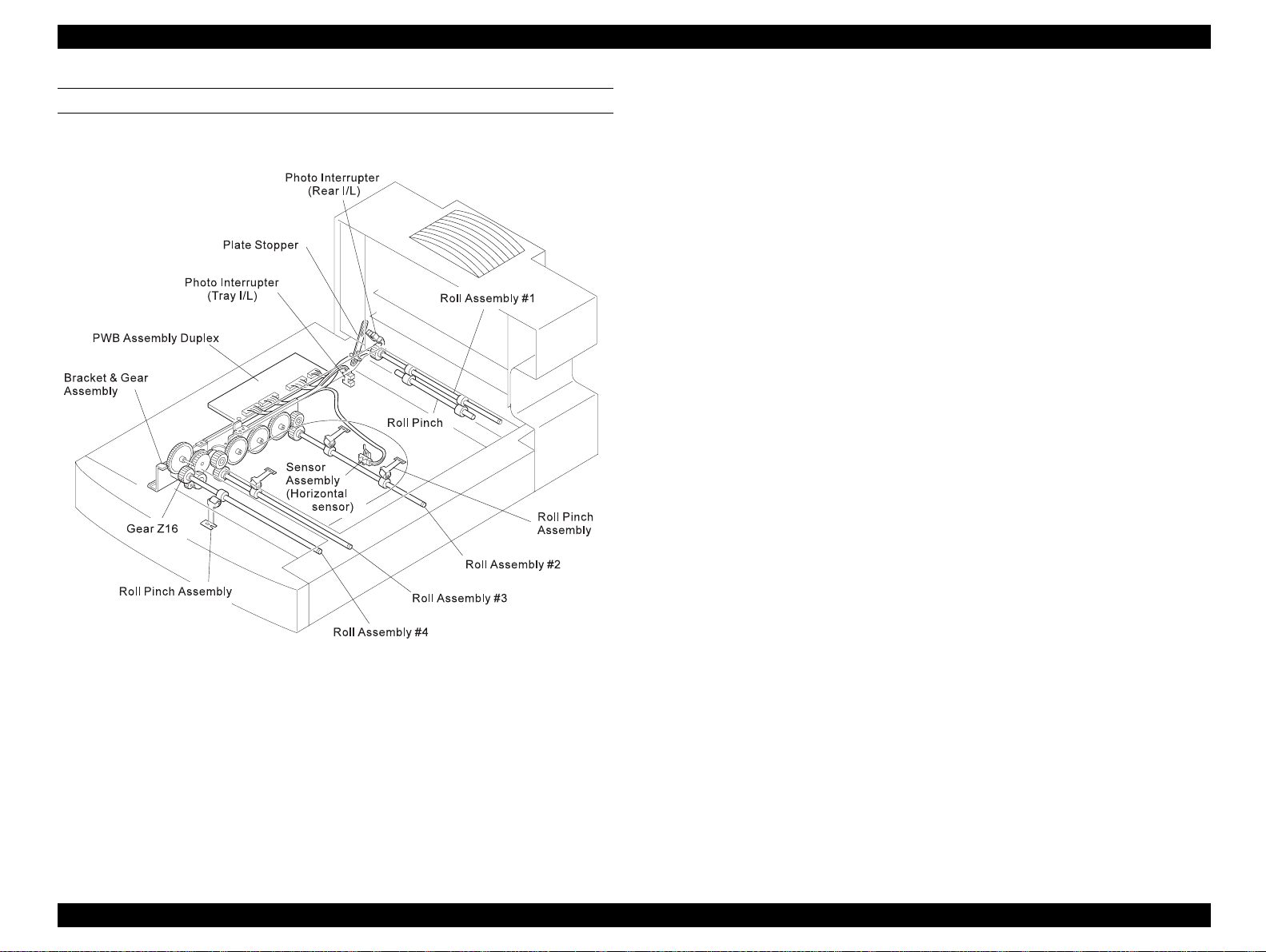
HORIZONTAL UNIT
Bracket & Gear Assembly:Receives the drive power from the Base
ine, and transmits it to Roll Assemblies
En
#2, #3, and #4 of the Horizontal Unit.
Roll Assembly #: Receives the drive power from the Motor
Duplex and Gear Cluster which are p art of the
Vertical Unit. Roll Assembly #1 rotates
forward when receivin
the first side printed. Roll Assembly #1 then
rotates in reverse to drive the sheet to Roll
Assembly #2 in preparation for printin
second side of the sheet.
Roll Assemblies#2/3/4: Drive the paper into and out of the Duplex
Unit.
PWBA Assembly Duplex: Controls the Duplex Unit operation. The 4-bit
MPU on the PWBA Duplex receives
commands from the PWBA MMCU, receives
nals from the Sensors within the Duplex
si
Unit, actuates the Solenoid Duplex, and the
Motor Duplex, and returns the status of the
Duplex Unit.
a sheet of paper with
the
Horizontal Sensor: Detects when a sheet of paper reaches Roll
Assembly #2.
Figure 2-7. Duplex Unit - Horizontal Unit Components
Duplex Unit ChuteCover Interlock:
Photo interrupter (PL11.24) that monitors
whether or not the Duplex Unit Chute Cover
is in place.
Vertical Unit Interlock: Photo interrupter (PL11.24) that monitors
whether or not the Vertical Unit is in position
ainst the rear of the Base Engine.
a
Rev. 0 18
Page 19

EPSON EPL-N1600/Duplex Unit Chapter 2 Operating Principles
gg
Plate Stopper: Support and limiting arm for the Vertical Unit
Solenoid: To
les the Gate Upper.
Rev. 0 19
Page 20

TROUBLESHOOTING
Page 21

EPSON EPL-N1600/Duplex Unit Chapter 3 Troubleshooting
This chapter is not appliacble to the Duplex Unit.
Rev. 0 21
Page 22

DISASSEMBLY AND ASSEMBLY
Page 23

EPSON EPL-N1600 / Duplex Unit Chapter 4 DISASSEMBLY AND ASSEMBLY
g
g
4.1 OVERVIEW
This chapter explains how to disassemble the Duplex Unit and its
various mechanisms. Except where otherwise indicated, the
reassembly procedure is the reverse of the disassembly procedure.
4.1.1 Precautions
This section describes the precautions you must take to prevent
accidents durin
out all work in accordance with the pre cautions and
provided in this manual.
CAUTION
disassembly and reassembly work. Be sure to carry
eneral instructions
Be careful to avoid injury from frame edges and other
sharp or protruding areas of the printer.
Avoid touching IC elements with bare hands, so as to
prevent possible damage from electrostatic
discharge. If you need to touch these areas, wear
appropriate electrostatic protection gear
(electrostatic wrist band, etc.) .
To ensure work efficiency and safety, use only the
tools specified in this manual.
The unit uses screws of many differen t types. Be sur e
to note the correct location for each screw before
removing it. Inserting screws into the wrong places
may strip or damage the screw holes.
4.1.2 Tools
The following table lists the tools you need to disassemble and
reassemble the printer.
Table 4-1. Required Tools
Market
Tool
Phillips screwdriver Yes B743800200
Tweezers Yes B641000100
Round nose pliers Yes B740400100
Availability
Code
Rev. 0 23
Page 24

EPSON EPL-N1600 / Duplex Unit Chapter 4 DISASSEMBLY AND ASSEMBLY
g
4.2 DISASSEMBLY AND ASSEMBLY
This section describes the procedures for disassembling the Duplex
Unit. The assembly of the unit can be made by performin
disassembly step in reverse order unless otherwise specified, and the
assembly procedure is therefore omitted in thi s manual.
the
Rev. 0 24
Page 25

EPSON EPL-N1600 / Duplex Unit Chapter 4 DISASSEMBLY AND ASSEMBLY
g
g
g
g
g
F4-1a
4.2.1 Duplex Unit Removal
1. Switch OFF printer power and remove the AC power cord from the
rear of the printer.
2. Disconnect all interface cable s from the rear of the printer.
3. Remove the 500 Sheet Feeder, if one is installed.
4. Push the Vertical Unit release lever to the rear (1) and tilt the
Vertical Unit away from the printer (2).
5. Press the Feeder Joint Clips to
feeder joints securin
the Duplex Unit to the Printer.
ether and remove the two rear
6. Remove the 250 Sheet Cassette and the Chute Assembly (4).
7. Press the feeder joint clips to
joints securin
8. Lift the base en
the Duplex Unit to the printer (5).
ine off of the Duplex Unit.
ether and remove the two front feeder
F4-1b
Figure 4-1. Duplex Unit Removal
Rev. 0 25
Page 26

EPSON EPL-N1600 / Duplex Unit Chapter 4 DISASSEMBLY AND ASSEMBLY
g
g
g
4.2.2 Duplex Assembly Unit Vertical
1. Remove the Duplex Unit.
2. Remove the Chute Upper.
3. Slide the end of the Plate Stopper off of the post on the Frame L/H
(1).
4. Tilt back the Vertical Unit (2).
5. Remove the wire clamp that holds the harness.
6. Remove the Bracket Sensor of t he Rear Inter lock Swi tch ( PL11.1 .9:
Photo Interrupter) (4).
7. Disconnect J230 (5).
F4-2a
8. Remove the two screws that are securin
round wire to the Frame L/H (6).
and
the Plate Assembly Pivot
9. Pry off the Plate Assembly Pivot (7).
10. Slide the Duplex Assembly Unit Vertical to the left to free the ri
ht
pivot from the Horizontal Unit, and remove the Vertical Un it.
F4-2b
Figure 4-2. Duplex Assembly Unit Vertical Removal
Rev. 0 26
Page 27

EPSON EPL-N1600 / Duplex Unit Chapter 4 DISASSEMBLY AND ASSEMBLY
g
4.2.3 Chute Cover
1. Remove the Duplex Unit.
2. Remove the Chute Upper.
3. Remove the Duplex Assembly Unit Vertical.
4. Remove the two screws that sec ure the Plate Cover to the Frame L/
H, and remove the Plate Cover.
5. Remove the seven screws that are securin
Duplex Assembly Unit Vertical.
6. Lift the Duplex Assembly Unit Vertical out of the Chute Cover.
the Chute Cover to the
Figure 4-3. Chute Cover Removal
Rev. 0 27
Page 28

EPSON EPL-N1600 / Duplex Unit Chapter 4 DISASSEMBLY AND ASSEMBLY
4
4.2.4 Fan Assembly Duplex
1. Remove the Duplex Unit.
2. Remove the Chute Upper.
3. Remove the Duplex Assembly Unit Vertical.
4. Remove the Chute Cover.
5. Disconnect P249/J2491 and route the Harness Vertical out of the
Frame.
6. Remove the two screws that secure the Fan Assembly Duplex to
the Bracket Fan.
7. Remove the Fan.
Figure 4-4. Fan Assembly Duplex Removal
Rev. 0 28
F4-
Page 29

EPSON EPL-N1600 / Duplex Unit Chapter 4 DISASSEMBLY AND ASSEMBLY
g
4.2.5 Sensor Assembly (Vertical)
1. Remove the Duplex Unit.
2. Remove the Chute Upper.
3. Remove the Duplex Assembly Unit Vertical.
4. Remove the Chute Cover.
5. Remove the Fan Assembly Duplex.
6. Disconnect J246 from the Sensor Assembly (Vertical).
7. Press in on the latchin
Frame, and remove the Sensor.
clips that are securing the Sensor to the
Figure 4-5. Sensor Assembly (Vertical) Removal
Rev. 0 29
Page 30

EPSON EPL-N1600 / Duplex Unit Chapter 4 DISASSEMBLY AND ASSEMBLY
g
4.2.6 Motor Duplex
1. Remove the Duplex Unit.
2. Remove the Chute Upper.
3. Remove the Duplex Assembly Unit Vertical.
4. Remove the Chute Cover.
5. Disconnect J244 from the Motor Duplex.
6. Remove the two screws that are securin
Bracket, and remove the Motor.
the Motor Duplex to the
Figure 4-6. Motor Duplex Removal
Rev. 0 30
Page 31

EPSON EPL-N1600 / Duplex Unit Chapter 4 DISASSEMBLY AND ASSEMBLY
g
4.2.7 Solenoid
1. Remove the Duplex Unit.
2. Remove the Chute Upper.
3. Remove the Duplex Assembly Unit Vertical.
4. Remove the Chute Cover.
5. Disconnect J2471 (Solenoid) from P247.
6. Free the harness of the Solenoid from the wire clamp.
7. Turn the Chute Cover upside down.
8. Remove the screw that is securin
9. Remove the Solenoid.
the Solenoid to the Frame L/H.
Figure 4-7. Solenoid Removal
Rev. 0 31
Page 32

EPSON EPL-N1600 / Duplex Unit Chapter 4 DISASSEMBLY AND ASSEMBLY
g
g
g
g
4.2.8 Shaft Latch & Lever
1. Remove the Duplex Unit.
2. Remove the Chute Upper.
3. Remove the Duplex Assembly Unit Vertical.
4. Remove the Chute Cover.
5. Remove the screw that is securin
and remove the Latch.
6. Remove the Sprin
7. Remove the screw that is securin
and remove the Latch.
8. Slide the Shaft Latch, alon
out of the Frame.
that is attached to the right Latch.
with the attached Lever, to the right and
the left Latch to the Shaft Latch,
the right Latch to the Shaf t Latch,
Figure 4-8. Shaft Latch/Lever Removal
Rev. 0 32
Page 33

EPSON EPL-N1600 / Duplex Unit Chapter 4 DISASSEMBLY AND ASSEMBLY
g
g
g
g
g
-
4.2.9 Rolls Pinch & Roll Assembly Exit
1. Remove the Duplex Unit.
2. Remove the Chute Upper.
3. Remove the Duplex Assembly Unit Vertical.
4. Remove the Chute Cover.
5. Remove the Fan Assembly Duplex.
6. Remove the three screws that secure the Bracket Fan to the Chute
Upper 2 and Plate Tie.
7. Remove the E-rin
s from both ends of the shaft of the Roll
Assembly Exit.
8. Remove the Bearin
9. Remove the Gear and Bearin
10. Slide the shaft to the left until the ri
11. Slide the shaft to the ri
from the right end of the shaft.
from the left end of the shaft.
ht end is freed from the Frame.
ht and out of the Frame.
12. Press down each Roll Pinch clip and remove the three Pinch Rolls
from the Chute.
F4
Figure 4-9. Rolls Pinch/Roll Assembly Exit Removal
Rev. 0 33
Page 34

EPSON EPL-N1600 / Duplex Unit Chapter 4 DISASSEMBLY AND ASSEMBLY
g
g
g
g
g
g
4.2.10 Chute Lower & Roll Assembly
1. Remove the Duplex Unit.
2. Remove the Chute Upper.
3. Remove the Duplex Assembly Unit Vertical.
4. Remove the Chute Cover.
5. Remove the two screws that are securi n
the Frame R/H and Bracket Pivot R/H.
6. Pull the Frame R/H away from the Chute Invert-V/TRA so you can
free the Chute Lower ri
7. Slide the Chute Lower to the ri
pivot from the Frame L/H and remove the Chute Lower from the
Frame.
8. Remove the E-rin
Assembly.
9. Remove the Bearin
10. Remove the Gear and Bearin
11. Lift the Roll Assembly off of the Chute Lower.
ht pivot from the Frame R/H.
ht and free the Chute Lower left
s from both ends of the shaft of the Roll
from the right end of the shaft:
from the left end of the shaft.
the Chute Invert-V/TRA to
Figure 4-10. Chute Lower/Roll Assembly Removal
Rev. 0 34
Page 35

EPSON EPL-N1600 / Duplex Unit Chapter 4 DISASSEMBLY AND ASSEMBLY
g
g
g
g
4.2.11 Photo Interrupters (Rear I/L & Chute Cover I/ L)
1. Remove the Duplex Unit.
2. Slide the end of the Plate Stopper off of the post on the Frame L/H.
See the illustration (1).
3. Tilt back the Duplex Assembly Unit Vertical.
PHOTO INTERRUPTER (PL11.1.9: REAR INTERLOCK)
4. Remove the two screws that is securin
Sensor to the Frame.
5. Remove the Bracket, alon
6. Disconnect J2732 from the Rear Interlock Swit ch.
7. Press in on the lockin
from the Bracket.
PHOTO INTERRUPTER (PL11.2.15: CHUTE COVER INTERLOCK)
8. Remove the Chute Upper.
9. Slide the Chute Assembly out of Duplex Unit.
10. Press in on the lockin
Switch from the Support Duplex-L/H.
11. Disconnect J2733 from the Chute Cover Interlock Switch.
with the attached Rear I nt erlock Switch.
clips and remove the Rear Interlock Switch
clips and remove the Cute Cover Interlock
the Rear Interlock Bracket
Figure 4-11. Photo Interrupter (Rear I/L, Chute Cover I/L) Removal
Rev. 0 35
Page 36

EPSON EPL-N1600 / Duplex Unit Chapter 4 DISASSEMBLY AND ASSEMBLY
g
4.2.12 Chute Upper
1. Tilt back the Duplex Assembly Unit Vertical.
2. Remove the four screws that are securin
Horizontal Unit.
3. Remove the Chute Upper.
the Chute Upper to the
Figure 4-12. Chute Upper Removal
Rev. 0 36
Page 37

EPSON EPL-N1600 / Duplex Unit Chapter 4 DISASSEMBLY AND ASSEMBLY
g
F
4.2.13 Sensor Assembly (Horizontal)
1. Remove the Duplex Unit.
2. Remove the Chute Assembly.
3. Remove the Plate Base.
4. Disconnect J2731 from the Sensor Assembly (Horizontal).
5. Press in on the lockin
(Horizontal) from the Chute Assembly.
clips and remove the Sensor Assembly
Figure 4-13. Sensor Assembly (Horizontal) Removal
Rev. 0 37
Page 38

EPSON EPL-N1600 / Duplex Unit Chapter 4 DISASSEMBLY AND ASSEMBLY
g
g
g
g
g
g
g
4.2.14 Roll Assembly #1 & Pinch Roll
1. Remove the Duplex Unit.
2. Slide the end of the Plate Stopper off of the post on the Frame L/H.
See illustration (1).
3. Tilt back the Duplex Assembly Unit Vertical.
4. Remove the Chute Upper.
5. Remove the two screws that are securin
Duplex R/H and L/H and remove the Chute (1).
6. Loosen the screw that secures the Rear Interl ock Swit ch (PL11.1. 8:
Bracket Sensor) to the Duplex Unit Horizontal II (PL11.2) (2).
7. Remove the E-rin
8. Remove the bearin
9. Remove the
#1.
10. Lift the shaft up and out of the Chute.
11. Slide the shaft to the ri
12. Unhook and remove the two Sprin
the Chute.
13. Remove the two Brackets Pinch alon
Chute.
s from both ends of Roll Assembly #1.
from the right end of the Roll Assembly #1.
ear and bearing from the left end of the Roll Assembly
ht and out of the Chute.
the Chute to the Supports
s that hold the Brackets Pinch to
with the Roll Pinch from the
14. Remove the two Brackets Pinch from the ends of the Pinch Roll.
Figure 4-14. Roll Assembly #1/Pinch Roll Removal
Rev. 0 38
Page 39

EPSON EPL-N1600 / Duplex Unit Chapter 4 DISASSEMBLY AND ASSEMBLY
g
4.2.15 Plate Base
1. Remove the Duplex Unit.
2. Slide the end of the Plate Stopper off of the post on the Frame L/H.
See the illustration (1).
3. Tilt back the Vertical Unit.
4. Turn the Duplex Unit upside down.
5. Remove the ei
Horizontal Unit, and remove the Plate Base.
ht screws that are securing the Plate Base to the
Figure 4-15. Plate Base Removal
Rev. 0 39
Page 40

EPSON EPL-N1600 / Duplex Unit Chapter 4 DISASSEMBLY AND ASSEMBLY
g
g
g
g
g
g
g
4.2.16 Roll Assemblies #2 & #3
1. Remove the Duplex Unit.
2. Remove the Plate Base.
3. Set the Horizontal Unit on the Support Duplex L/H-.
4. Remove the two screws that are securin
the Support Duplex-R/H.
5. Carefully pull the Chute Assembly a few inches away from the
Support.
6. Remove the E-rin
rubber rolls).
7. Remove the bearin
8. Slide the Roll Assembly #2 down to free the bearin
end of the Assembly.
9. Pull the top end of the Roll Assembly #2 away from the Horizontal
Unit and remove the Assembly.
10. Remove the E-rin
rubber roll).
11. Remove the bearin
12. 1Slide Roll Assembly #3 down to free the bearin
of the Assembly.
from the end of Roll Assembly #2 (shaft with two
from the top end of Roll Assembly #2.
from the end of Roll Assembly #3 (shaft with one
from the top end of Roll Assembly #3.
the Chute Assembly to
at the bottom
at the bottom end
13. Pull the top end of the Roll Assembly #3 away from the Horizontal
Unit and remove the Assembly.
Figure 4-16. Roll Assemblies #2/#3 Removal
Rev. 0 40
Page 41

EPSON EPL-N1600 / Duplex Unit Chapter 4 DISASSEMBLY AND ASSEMBLY
g
4.2.17 PWB Assembly Duplex
1. Remove the Duplex Unit.
2. Disconnect J263, J272, J273, and J274 from the PWB Assembly
Duplex.
3. Remove the screw that is securin
the Support Duplex-L/H.
4. Slide the end of the PWB out of the slot in the Support Duplex L/H
and remove the PWB.
the PWB Assembly Duplex to
Figure 4-17. PWB Assembly Duplex Removal
Rev. 0 41
Page 42

EPSON EPL-N1600 / Duplex Unit Chapter 4 DISASSEMBLY AND ASSEMBLY
g
g
g
4.2.18 Bracket & Gear Assembly
1. Remove the Duplex Unit.
2. Remove the PWB Assembly Duplex.
3. Slide the Chute Assembly out from the Duplex Unit.
4. Remove the two screws that are securin
the Plate Tie to the
Support Duplex-L/H and Support Duplex-R/H, and remove the Pl ate
Tie.
5. Remove the three screws that are securin
the Bracket & Gear
Assembly to the Support Duplex L/H. The rear screw also secures a
round wire to the Bracket. The middle screw also secures the
Bracket PWBA to the Gear Assembly Bracket.
6. Pull up and tilt back the Gear Assembly as you carefu lly re mov e the
Gear Assembly from the Support Duplex L/H.
CAUTION
The Gear Assembly gears are not secured to their
respective shafts, and they can slide off during Gear
Assembly removal. Tilt the Gear Assembly back to
keep the gears in place during removal and
replacement.
Figure 4-18. Bracket & Gear Assembly Removal
Rev. 0 42
Page 43

ADJUSTMENT
Page 44

EPSON EPL-N1600/Duplex Unit Chapter 5 Adjustment
There is no adjustment required when repairing the Duplex Unit.
Rev. 0 45
Page 45

MAINTENANCE
Page 46

EPSON EPL-N1600/Duplex Unit Chapter 6 Maintenance
There is no specific maintenance required for the duplex unit.
Rev. 0 47
Page 47

APPENDIX
Page 48

EPSON EPL-N1600/Duplex Unit Chapter 7 Appendix
7.1 Connector Location
Connector Location Harness
J229
P/J230
P/J244 9 Harness Vertical
P/J246 10 Harness Vertical
P/J247
J2471
P/J249
J2491
J252 5 Harness 15P
P/J263 3 Harness 15P
P/J272 4 Harness 7P
P/J273 1 Harness Sensor 9P
P/J2731 13 Harness Sensor 9P
P/J2732 11 Harness Sensor 9P
P/J2733 12 Harness Sensor 9P
P/J274 2 Harness Sensor Horizontal
P/J282 14 Harness 7P
6 Harness Sensor Horizontal
Harness Vertical
8 @ Solenoid *1
Harness Vertical
7 @ Fan Assembly Duplex
Harness Vertical
*1:"@" mark at the beginning of a harness name indicates that the subject harness is a
part of the component from where the harness extends.
Figure 7-1. Connector Location Diagram
Rev. 0 49
Page 49

EPSON EPL-N1600/Duplex Unit Chapter 7 Appendix
7.2 Exploded Diagram
DUPLEX UNIT (OPTIONAL)
1. Duplex Unit
(with PL10.2, PL10.3, PL10.4, PL11.1, PL11.2, PL12.1 and 5~8)
2. Reference only (Exploded on PL10.2, PL10.3, PL10.4)
3. Reference only (Exploded on PL11.1, PL11.2)
4. Reference only (Exploded on PL12.1)
5. Clip Chute $
6. Chute Duplex
7. Plate Cap
8. Joint Feeder (PL9.1.22) $
Rev. 0 50
Page 50

Page 51

EPSON EPL-N1600/Duplex Unit Chapter 7 Appendix
DUPLEX UNIT VERTICAL I
1. Duplex Assembly Unit Vertical (with 2 - 5, PL10.3, PL10.4) $
2. Sensor Assembly $
3. Bracket Fan
4. Fan Assembly Duplex $
5. Chute Cover
6. --
Rev. 0 52
Page 52

Page 53

EPSON EPL-N1600/Duplex Unit Chapter 7 Appendix
g
g
g
g
DUPLEX UNIT VERTICAL II
1. Harness Vertical
2. Clamp NSB1207
3. Bracket
4. Motor Duplex $
5. Gear
6. Wire
7. Plate Cover
8. Gear
9. Sprin
10. Gear
11. Gear
Torsion-Latch LH
19. Bracket
20. Frame R/H
21. Sprin
22. Plate Assembly Pivot
Torsion-Latch RH
12. Frame L/H
13. Solenoid $
14. Gear
15. Gear Idler
16. Sprin
17. Roll Trackin
18. Gear Idler
Extension
Rev. 0 54
Page 54

Page 55

EPSON EPL-N1600/Duplex Unit Chapter 7 Appendix
g
g
g
g
g
g
g
DUPLEX UNIT VERTICAL III
1. Chute Lower
2. Bearin
3. Roll Assembly
4. Bearin
5. Gear
6. Chute Lower
7. Sprin
8. Chute Invert-V/TRA
9. Chute Upper
10. Sprin
11. Sprin
Earth
R
L
19. Sprin
20. Roll Assembly Exit
21. Gate Upper
22. Lever
23. Bracket Pivot R/H
12. Plate Tie
13. Roll Pinch
14. Chute Upper 2
15. Bearin
16. Gear
17. Latch
18. Shaft Latch
Rev. 0 56
Page 56

Page 57

EPSON EPL-N1600/Duplex Unit Chapter 7 Appendix
g
g
g
g
DUPLEX UNIT HORIZONTAL I
1. Duplex Assembly Unit Horizontal (with 2 - 24, PL11.2, PL12.1) $
2. Roll Assembly #3
3. Roll Assembly #2
4. Chute Assembly
5. Bearin
6. Gear Z16
7. Guide
8. Bracket Sensor
9. Photo Interrupter $
10. Chute Upper
11. GearA
19. Chute Lower
20. Plate Pivot R/H
21. Sprin
22. Sensor Assembly $
23. Support Duplex-R/H
24. Plate Base
Earth
12. Roll Assembly #1
13. Bearin
14. Chute
15. Bracket Pinch
16. Sprin
17. Roll Pinch
18. Plate Tie
Rev. 0 58
Page 58

Page 59

EPSON EPL-N1600/Duplex Unit Chapter 7 Appendix
g
g
g
DUPLEX UNIT HORIZONTAL II
1. Support Duplex-L/H
2. Bracket & Gear Assembly
3. Bracket PWBA
4. Sprin
5. Sprin
6. PWBA Assembly Duplex $
7. Harness Sensor 9P
8. Harness Sensor Horizontal
9. Plate Stopper
10. Pin
11. Harness 15P
12. Sprin
13. Plate Pivot L/H
14. Harness 7P
15. Photo Interrupter $
Earth
Earth
Rev. 0 60
Page 60

Page 61

EPSON EPL-N1600/Duplex Unit Chapter 7 Appendix
g
g
g
DUPLEX UNIT CHUTE
1. Chute Assembly (with 2 - 13) $
2. Chute
3. Roll Pinch Assembly
4. Roll Pinch Assembly
5. Chute Pass A
6. Sprin
7. Chute Pass B
8. Roller Assembly # 4
9. Sprin
10. Bearin
11. Gear Z16
12. Roll Pinch Assembly
13. Cover Front
Earth
Earth
Rev. 0 62
Page 62

 Loading...