

Page 1
EPSON TERMINAL PRINTER
EPL-N1200
SERVICE MANUAL
EPSON
4006838
Page 2

All rights reserved. Reproduction of any part of this manual in any form whatsoever without
SEIKO EPSON’s express written permission is forbidden.
The contents of this manual are subjects to change without notice.
All efforts have been made to ensure the accuracy of the contents of this manual. However, should
any errors be detected, SEIKO EPSON would greatly appreciate being informed of them.
The above notwithstanding SEIKO EPSON can assume no responsibility for any errors in this
manual or the consequence thereof.
Epson is a registered trademark of Seiko Epson Corporation.
General Notice: Other product names used herein are for identication purposes only and may be
trademarks of their respective campanies.
Copyright 0 1996 by SEIKO EPSON CORPORA
_i-
T/ON
Nagano, Japan
Page 3

PRECAUTIONS
Precautionary notations throughout the text are categorized relative to 1) personal injury and 2)
damage to equipment.
DANGER
WARfVlNG
The precautionary measures itemized below should always be observed when performing repair/
maintenance procedures.
Signals a precaution which, if ignored, could result in serious or fatal personal injury.
Great caution should be exercised in performing procedures preceded by DANGER
Headings.
Signals a precaution which, if ignored, could result in damage to equipment.
DANGER
ALWAYS DISCONNECT THE PRODUCT FROM BOTH THE POWER SOURCE AND PERIPHERAL DEVICES PERFORMING ANY MAINTENANCE OR REPAIR PROCEDURE.
NO WORK SHOULD BE PERFORMED ON THE UNIT BY PERSONS UNFAMILIAR WlTH
BASIC SAFETY MEASURES AS DICTATED FOR ALL ELECTRONICS TECHNICIANS IN
THEIR LINE OF WORK.
WHEN PERFORMING TESTING AS DICTATED WITHIN THIS MANUAL, DO NOT CONNECT THE UNIT TO A POWER SOURCE UNTIL INSTRUCTED TO DO SO. WHEN THE
POWER SUPPLY CABLE MUST BE CONNECTED, USE EXTREME CAUTION IN WORKING
ON POWER SUPPLY AND OTHER ELECTRONIC COMPONENTS.
WA
FINING
REPAIRS ON EPSON PRODUCT SHOULD BE PERFORMED ONLY BY AN EPSON CERTIFIED
1.
REPAIR TECHNICIAN.
MARE CERTAIN THAT THE SOURCE VOLTAGE IS THE SAME AS THE RATED VOLTAGE,
2.
LISTED ON THE SERIAL NUMBER/RATING PLATE. IF THE EPSON PRODUCT HAS A
PRIMARY AC RATING DIFFERENT FROM AVAILABLE POWER SOURCE, DO NOT CONNECT IT TO THE POWER SOURCE.
ALWAYS VERIFY THAT THE EPSON PRODUCT HAS BEEN DISCONNECTED FROM THE
3.
POWER SOURCE BEFORE REMOVING OR REPLACING PRINTED CIRCUIT BOARDS
AND/OR INDMDUAL CHIPS.
IN ORDER TO PROTECT SENSITIVE MICROPROCESSORS AND CIRCUITRY, USE STATIC
4.
DISCHARGE EQUIPMENT, SUCH AS ANTI-STATIC WRIST STRAPS, WHEN ACCESSING
INTERNAL COMPONENTS.
REPLACE MALFUNCTIONING COMPONENTS ONLY WITH THOSE COMPONENTS BY
5.
THE MANUFACTURE; INTRODUCTION OF SECOND-SOURCE ICs OR OTHER NONAP-
PROVED COMPONENTS MAY DAMAGE THE PRODUCT AND VOID ANY APPLICABLE
EPSON WARRANTY.
Page 4
SAFETY INFORMATION
This printer is a page printer which operates by means of a laser. There is no possibility of danger from
the laser, provided the printer is operated according to the instructions in this manual provided.
Since radiation emitted by the laser is completely confined within protective housings, the laser beam
cannot escape from the machine during any phase of user operation.
For United States Users;
[Laser Safety]
This printer is certified as a Class 1 Laser product under the U.S. Department of Health
and Human Services (DHHS) Radiation Performance Standard according to the Radiation Control for Health and Safety Act of 1968. This means that the printer does not
produce hazardous laser radiation.
ICDRH Regulations]
The Center for Devices and Radiological Health (CDRH) of the U.S. Food and Drug
Administration implemented regulations for laser products on August
ance is mandatory for products marketed in the United States. The label shown below
indicates compliance with the CDRH regulations and must be attached to laser products
marketed in the United States.
2,1976.
Compli-
WARNING : Use of controls, adjustments or performance of procedures other
than those specified in this manual may result in hazardous radiation exposure.
[Internal Laser Radiation]
Maximum Radiation Power:
Wave Length:
This is a Class
unit is NOT A FIELD SERVICE ITEM. Therefore, the print head unit should not be
opened under any circumstances.
For Other Countries Users;
WARNING: Use of controls, adjustments or performance of procedures other
than those specified in this manual may result in hazardous radiation exposure.
This is a semiconductor laser. The maximum power of the laser diode is 5.0
lo4
W and the wavelength is 790 + 20 nm.
I
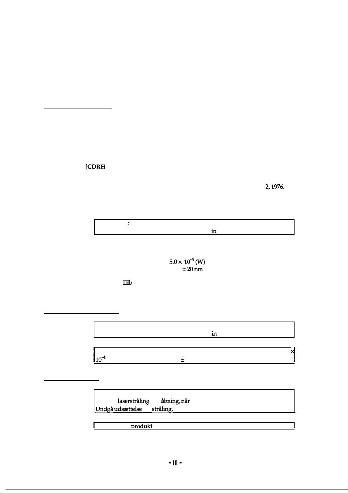
For Denmark Users;
5.0x lO-QW)
790
f20nm
IIIb
Laser Diode Assay that has an invisible laser beam. The print head
1
ADVARSEL
Usynlig
Undga udsaettelse
1
Klasse 1 laser
laserstr&ling
nrodukt
ved
Abning, r&r
for
strtig.
der onfvlder IEC825 sikkerheds kravene.
- III
sikkerhedsafbrydere er ude af funktion
. . .
-
I
Page 5
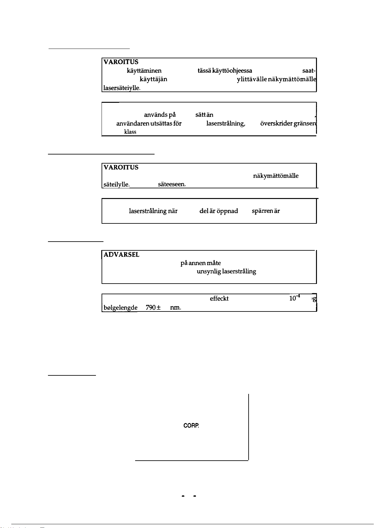
For Finland. Sweden Users:
vARoITus
Laitteen kayttaminen muulla kuin t&&i kayttoohjeessa mainitulla tavalla saat-
taa altistaa
kayttajan
lasersateiylle.
VARNING
Om apparaten anvands pa at-mat
kan
anvandaren
for laser klass
utsattas for osynlig
1.
For Finland, Sweden Service People
vARoITus
Avattaessa ja suojalukitus ohitettaessa olet alttiina
sateilylle.
Ala katso
VARNING
Osynlig
laserstr&lning
Betrakta ei strblen.
turvallisuusluokan 1
sHtt an
i denna bruksanvisning specificerats
laserstr&ing,
sateeseen.
nar denna
de1 3r oppnad
ylittaville
nakymatt6mHlle
som over&rider
nakymhttomalle
och
spirren Hr
gr%ns
laser
urkopplad
For Norway Users;
1
ADVARSEL
Dersom apparatet brukes pa
visning, kan brukeren utsettes for
annen mate
unsynlig
enn spesifisert i denne bruksan
laserstr%ng som over&rider gren
sen for laser klasse 1.
Dette er en halvleder laser. Maksimal
[bolgelengde
er
790 f
20
run.
effeckt
til laserdiode er 5.0 x
Laser Safety Labels
[Label on rear printer case]
A laser safety labels is attached on the outside of the printer shown below.
For United State
This laser product conforms to the applicable
requirement of 21 CFR
Chapter I, subchapter J.
SEIKO EPSON
Hirooka Office
80 Hirooka, Shiojiri-shi, Nagano-ken,
Japan
MANUFACTURED:
CORP.
lo4
W o
I
- iv
-
Page 6
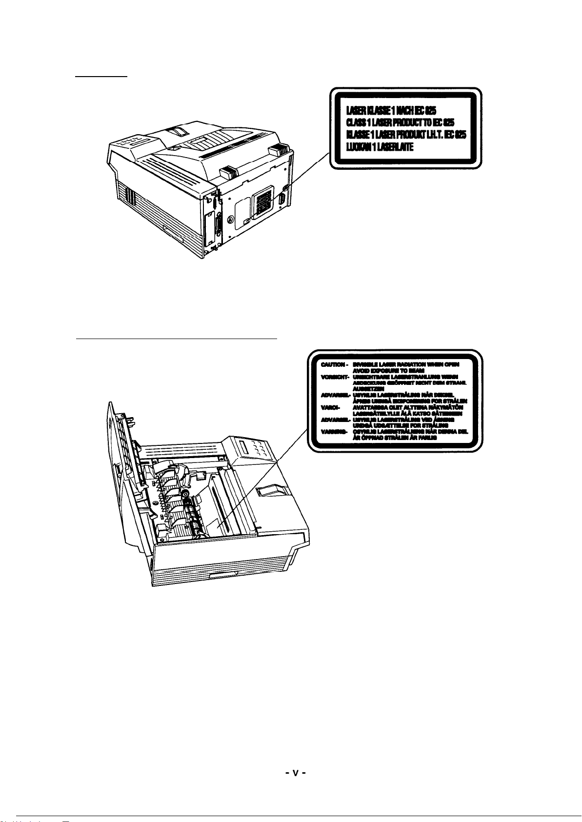
For Europe
[Label inside printer]
The following laser safely label will be attached inside the printer as shown below.
For Denmark, Finland, Sweden, and Norway
Page 7

This manual describes functions, theory of electrical and mechanical operations, maintenance, and repair
of
EPL-NlZOO.
The instructions and procedures included herein are intended for the experience repair technician, and
attention should be given to the precautions on the preceding page. The chapters are organized as
follows:
CHAPTER 1. GENERAL DESCRIPTION
Provides a general product overview, lists specifications, and illustrates the main components of the printer.
CHAPTER 2. OPERATING PRINCIPLES
Describes the theory of printer operation.
CHAPTER 3. DISASSEMBLY AND ASSEMBLY
Includes a step-by-step guide for product disassembly and assembly.
CHAPTER 4. ADJUSTMENTS
Includes a step-by-step guide for adjustment.
CHAPTER 5. TROUBLESHOOTING
Provides Epson-approved techniques for adjustment.
CHAPTER 6. MAINTENANCE
Describes preventive maintenance techniques and lists lubricants and adhesives required to service the equipment.
APPENDIX
Describes connector pin assignments, circuit diagrams, circuit board component layout and exploded diagram.
The contents of this manual are subject to change without notice.
- vi
-
Page 8
REVISION SHEET
I
Revision
Rev.
A
I
Issue Date
December 9 1996
Revision Page
1st issue
-
vii -
Page 9

TABLE OF CONTENTS
CHAPTER 1.
CHAPTER 2.
CHAPTER 3.
CHAPTER
CHAPTER
CHAPTER
APPENDIX
4.
5.
6.
GENERAL DESCRIPTION
OPERATING PRINCIPLES
DISASSEMBLY AND ASSEMBLY
ADJUSTMENTS
TROUBLESHOOTING
MAINTENANCE
-
. . .
VIII -
Page 10

Chapter 1 General Description
Table of Contents
1.1 FEATURES 1-1
1.2 SPECIFICATIONS 1-3
1.2.1 Basic Specifications . . . . . . . . . . . . . . . . . . . . . . . . . . . . . . . . . . . . . . . . . . 1-3
1.2.2 Electrical Specifications . . . . . . . . . . . . . . . . . . . . . . . . . . . . . . . . . . . . . . . 1-5
1.2.3 Reliability Specifications. . . . . . . . . . . . . . . . . . . . . . . . . . . . . . . . . . . . . . . 1-5
1.2.4 Environmental Conditions for Operating (Including Imaging Cartridge). . . 1-5
1.2.5 Environmental Condifitons for Storage and Transporation
(Excluding Image Cartridge). . . . . . . . . . . . . . . . . . . . . . . . . . . . . . . . . . . . 1-5
1.2.6 Applicable Standards (without any electrical optional unit) . . . . . . . . . . . . 1-6
1.2.7 Specification for Consumable (Imaging Cartridge) . . . . . . . . . . . . . . . . . . 1-6
1.2.8 Physical Specifications. . . . . . . . . . . . . . . . . . . . . . . . . . . . . . . . . . . . . . . . 1-6
1.2.9 Software Specifications . . . . . . . . . . . . . . . . . . . . . . . . . . . . . . . . . . . . . . . 1-7
1.2.10 Lower Paper Cassette (Option) Specifications . . . . . . . . . . . . . . . . . . . 1-11
1.3 INTERFACE SPECIFICATIONS 1-12
1.3.1 Parallel Interfaces. . . . . . . . . . . . . . . . . . . . . . . . . . . . . . . . . . . . . . . . . . . 1-12
1.3.1.1 Compatibility (Standard) Mode . . . . . . . . . . . . . . . . . . . . . . . . . . 1-12
1.3.1.2 Nibble (Reverse), ECP Mode . . . . . . . . . . . . . . . . . . . . . . . . . . . 1-14
1.3.2 Optional Serial Interface (LocalTalk/Serial Module). . . . . . . . . . . . . . . . . 1-18
1.4 OPERATING INSTRUCTIONS 1-22
1.4.1 Control Panel . . . . . . . . . . . . . . . . . . . . . . . . . . . . . . . . . . . . . . . . . . . . . . 1-22
1.4.2 SelecType Functions . . . . . . . . . . . . . . . . . . . . . . . . . . . . . . . . . . . . . . . . 1-24
1.4.3 Service Mode . . . . . . . . . . . . . . . . . . . . . . . . . . . . . . . . . . . . . . . . . . . . . . 1-29
1.4.3.1 Hexadecimal Dump Mode . . . . . . . . . . . . . . . . . . . . . . . . . . . . . . 1-29
1.4.3.2 EEPROM Format. . . . . . . . . . . . . . . . . . . . . . . . . . . . . . . . . . . . . 1-29
1.4.3.3 Error Recovery. . . . . . . . . . . . . . . . . . . . . . . . . . . . . . . . . . . . . . . 1-30
1.4.4 Display of Messages . . . . . . . . . . . . . . . . . . . . . . . . . . . . . . . . . . . . . . . . 1-31
1.4.4.1 Status Messages . . . . . . . . . . . . . . . . . . . . . . . . . . . . . . . . . . . . . 1-31
1.4.4.2 Error Messages . . . . . . . . . . . . . . . . . . . . . . . . . . . . . . . . . . . . . 1-32
1.4.4.3 Warning Message . . . . . . . . . . . . . . . . . . . . . . . . . . . . . . . . . . . . 1-33
1.4.5 Multi-User and Multi-Emulation . . . . . . . . . . . . . . . . . . . . . . . . . . . . . . . . 1-34
1.4.6 Emulation Mode Switch Function. . . . . . . . . . . . . . . . . . . . . . . . . . . . . . . 1-35
1.4.6.1 Emulation Switch by SPL. . . . . . . . . . . . . . . . . . . . . . . . . . . . . . . 1-35
1.4.6.2 Intelligent Emulation Switch. . . . . . . . . . . . . . . . . . . . . . . . . . . . . 1-35
1.4.7 Bi Resolution Improvement Technology . . . . . . . . . . . . . . . . . . . . . . . . . 1-36
1.4.8 Printer Initialization. . . . . . . . . . . . . . . . . . . . . . . . . . . . . . . . . . . . . . . . . . 1-37
1.4.9 Toner Save Mode. . . . . . . . . . . . . . . . . . . . . . . . . . . . . . . . . . . . . . . . . . . 1-38
Page 11

1.5 MAIN COMPONENTS 1-39
1.5.1 C205 MAIN Board. . . . . . . . . . . . . . . . . . . . . . . . . . . . . . . . . . . . . . . . . . 1-40
1.5.2 C173 PROG Board`. . . . . . . . . . . . . . . . . . . . . . . . . . . . . . . . . . . . . . . . . 1-41
1.5.3 Control Panel. . . . . . . . . . . . . . . . . . . . . . . . . . . . . . . . . . . . . . . . . . . . . . 1-41
1.5.4 Engine Coontroller Board . . . . . . . . . . . . . . . . . . . . . . . . . . . . . . . . . . . . 1-42
1.5.5 Power Supply Board . . . . . . . . . . . . . . . . . . . . . . . . . . . . . . . . . . . . . . . . 1-42
1.5.6 High-Voltage Supply Board. . . . . . . . . . . . . . . . . . . . . . . . . . . . . . . . . . . 1-43
1.5.7 Optical Unit . . . . . . . . . . . . . . . . . . . . . . . . . . . . . . . . . . . . . . . . . . . . . . . 1-43
1.5.8 Fusing Unit . . . . . . . . . . . . . . . . . . . . . . . . . . . . . . . . . . . . . . . . . . . . . . . 1-44
1.5.9 Imaging Cartridge . . . . . . . . . . . . . . . . . . . . . . . . . . . . . . . . . . . . . . . . . . 1-44
1.5.10 Lower Paper Cassette. . . . . . . . . . . . . . . . . . . . . . . . . . . . . . . . . . . . . . 1-45
List of Figures
Figure 1-1. EPL-N1200 Exterior View . . . . . . . . . . . . . . . . . . . . . . . . . . . . . . . . 1-1
Figure 1-2. Printable Area . . . . . . . . . . . . . . . . . . . . . . . . . . . . . . . . . . . . . . . . . 1-4
Figure 1-3. Compatibility Mode Signal Timing . . . . . . . . . . . . . . . . . . . . . . . . . 1-12
Figure 1-4. Parallel Interface State Switch Diagram . . . . . . . . . . . . . . . . . . . . 1-15
Figure 1-5. Negotiation Timing Chart . . . . . . . . . . . . . . . . . . . . . . . . . . . . . . . 1-16
Figure 1-6. Data Transfer Timing Chart . . . . . . . . . . . . . . . . . . . . . . . . . . . . . . 1-16
Figure 1-7. Termination Timing Chart . . . . . . . . . . . . . . . . . . . . . . . . . . . . . . . 1-17
Figure 1-8. Interrupt Timing Chart . . . . . . . . . . . . . . . . . . . . . . . . . . . . . . . . . . 1-17
Figure 1-9. Control Panel. . . . . . . . . . . . . . . . . . . . . . . . . . . . . . . . . . . . . . . . . 1-22
Figure 1-10. Multi-Port and Multi-Emulation. . . . . . . . . . . . . . . . . . . . . . . . . . . 1-34
Figure 1-11. Emulation Switch by SPL. . . . . . . . . . . . . . . . . . . . . . . . . . . . . . . 1-35
Figure 1-12. Intelligent Emulation Switch. . . . . . . . . . . . . . . . . . . . . . . . . . . . . 1-35
Figure 1-13. BiRITech Effect . . . . . . . . . . . . . . . . . . . . . . . . . . . . . . . . . . . . . . 1-36
Figure 1-14. RITech Adjustment . . . . . . . . . . . . . . . . . . . . . . . . . . . . . . . . . . . 1-36
Figure 1-15. Toner Save Mode . . . . . . . . . . . . . . . . . . . . . . . . . . . . . . . . . . . . 1-38`
Figure 1-16. Component Layout. . . . . . . . . . . . . . . . . . . . . . . . . . . . . . . . . . . . 1-39
Figure 1-17. C205 Main Board. . . . . . . . . . . . . . . . . . . . . . . . . . . . . . . . . . . . . 1-40
Figure 1-18. C173 PROG Board . . . . . . . . . . . . . . . . . . . . . . . . . . . . . . . . . . . 1-41
Figure 1-19. Control Panel . . . . . . . . . . . . . . . . . . . . . . . . . . . . . . . . . . . . . . . . 1-41
Figure 1-20. Engine Controller Board. . . . . . . . . . . . . . . . . . . . . . . . . . . . . . . . 1-42
Figure 1-21. Power Supply Board . . . . . . . . . . . . . . . . . . . . . . . . . . . . . . . . . . 1-42
Figure 1-22. High-Voltage Supply Board . . . . . . . . . . . . . . . . . . . . . . . . . . . . . 1-43
Figure 1-23. Optical Unit . . . . . . . . . . . . . . . . . . . . . . . . . . . . . . . . . . . . . . . . . 1-43
Figure 1-24. Fusing Unit. . . . . . . . . . . . . . . . . . . . . . . . . . . . . . . . . . . . . . . . . . 1-44
Figure 1-25. Imaging Cartridge . . . . . . . . . . . . . . . . . . . . . . . . . . . . . . . . . . . . 1-44
Figure 1-26. Lower Paper Cassette . . . . . . . . . . . . . . . . . . . . . . . . . . . . . . . . . 1-45
Page 12

List of Tables
Table 1-1. EPL-N1200 Options . . . . . . . . . . . . . . . . . . . . . . . . . . . . . . . . . . . . . . 1-2
Table 1-2. Paper Feed Methods . . . . . . . . . . . . . . . . . . . . . . . . . . . . . . . . . . . . . 1-3
Table 1-3. Paper Types. . . . . . . . . . . . . . . . . . . . . . . . . . . . . . . . . . . . . . . . . . . . 1-3
Table 1-4. Special Papers Usability . . . . . . . . . . . . . . . . . . . . . . . . . . . . . . . . . . 1-4
Table 1-5. Electrical Specifications . . . . . . . . . . . . . . . . . . . . . . . . . . . . . . . . . . . 1-5
Table 1-6. Differences between EPSON GL/2 and GL/2 in the
HP LaserJet 4 Emulation . . . . . . . . . . . . . . . . . . . . . . . . . . . . . . . . . . 1-7
Table 1-7. Built-in Fonts . . . . . . . . . . . . . . . . . . . . . . . . . . . . . . . . . . . . . . . . . . . 1-7
Table 1-8. Parallel Interface Pin Assignment . . . . . . . . . . . . . . . . . . . . . . . . . . 1-13
Table 1-9. Parallel Interface Pin Assignment . . . . . . . . . . . . . . . . . . . . . . . . . . 1-14
Table 1-10. Serial Interface Pin Assignments . . . . . . . . . . . . . . . . . . . . . . . . . . 1-19
Table 1-11. LocalTalk Interface Pin Assignments. . . . . . . . . . . . . . . . . . . . . . . 1-21
Table 1-12. SelecType Functions . . . . . . . . . . . . . . . . . . . . . . . . . . . . . . . . . . . 1-27
Table 1-13. Main Controller Board Default Paper Size Setting. . . . . . . . . . . . . 1-29
Table 1-14. Status Messages . . . . . . . . . . . . . . . . . . . . . . . . . . . . . . . . . . . . . . 1-31
Table 1-15. Error Messages . . . . . . . . . . . . . . . . . . . . . . . . . . . . . . . . . . . . . . . 1-32
Table 1-16. Warning Messages . . . . . . . . . . . . . . . . . . . . . . . . . . . . . . . . . . . . 1-33
Table 1-17. Differences in Components for the C205 MAIN Board . . . . . . . . . 1-40
Page 13

EPL-N1200 Service Manual General Description
1.1 FEATURES
The EPSONEPL-N1200 is a non-impact page printer that combines a semi-conductor laser with
electro-photographic technology. Resolution is 600/300 DPI and print speed is 12 PPM. The main
features are:
o Upward compatibility with the EPL-5600
o No ozone generation
o Printing speed — 12 PPM (pages per minute) for A4 size or letter paper
o Resolution — 600/300 DPI (dots per inch)
o Standard paper tray holds up to 250 sheets
o Standard paper tray can be used as manual feed slot
o Lower paper cassette (500 sheets ) available as option
o Small footprint because output tray is held within the printer
o Support of HP
IBM I239X mode in standard model
o 45 built-in scalable fonts (14 Windows TrueType compatible and 31 LJ4 compatible)
o With memory improvement technology, standard RAM supports 600 DPI at full-page size in all
modes (LJ4, GL/2, FX, ESC/P2, and I239X modes)
o High-performance controller (20 MHz SPARKlite (MB86930) CPU)
o Bi Resolution Improvement Technology (BiRITech) refines print quality, eliminating jagged
edges from images and characters on 600 and 300 DPI printing.
o Optional EPSONScript Level 2 (PostScript
o Optional LocalTalk/Serial Module and Type-B interfaces can be used simultaneously
o 2 MB standard RAM and up to 64 MB RAM using optional SIMMs
o Two bidirectional parallel interface ports, Parallel B and Parallel C
Parallel B : Supports IEEE 1284 compatible, Nibble modes
Parallel C: Supports IEEE 1284 compatible, Nibble, and ECP modes
o High-speed parallel communication rate
Parallel B : Approx. 400 KB / second in fast mode
Parallel C: Approx. 2 MB / second in ECP mode
o Support for EPA Energy Star program
o Multi-port and multi-emulation are supported
o IES (Intelligent Emulation Switch) allows switching between EPSONScript mode and other
mode
o Setting for automatic release of paper size errors
LaserJet4 (LJ4) emulation mode, EPSON GL/2 mode, ESC/P 2 mode, and
compatible) module
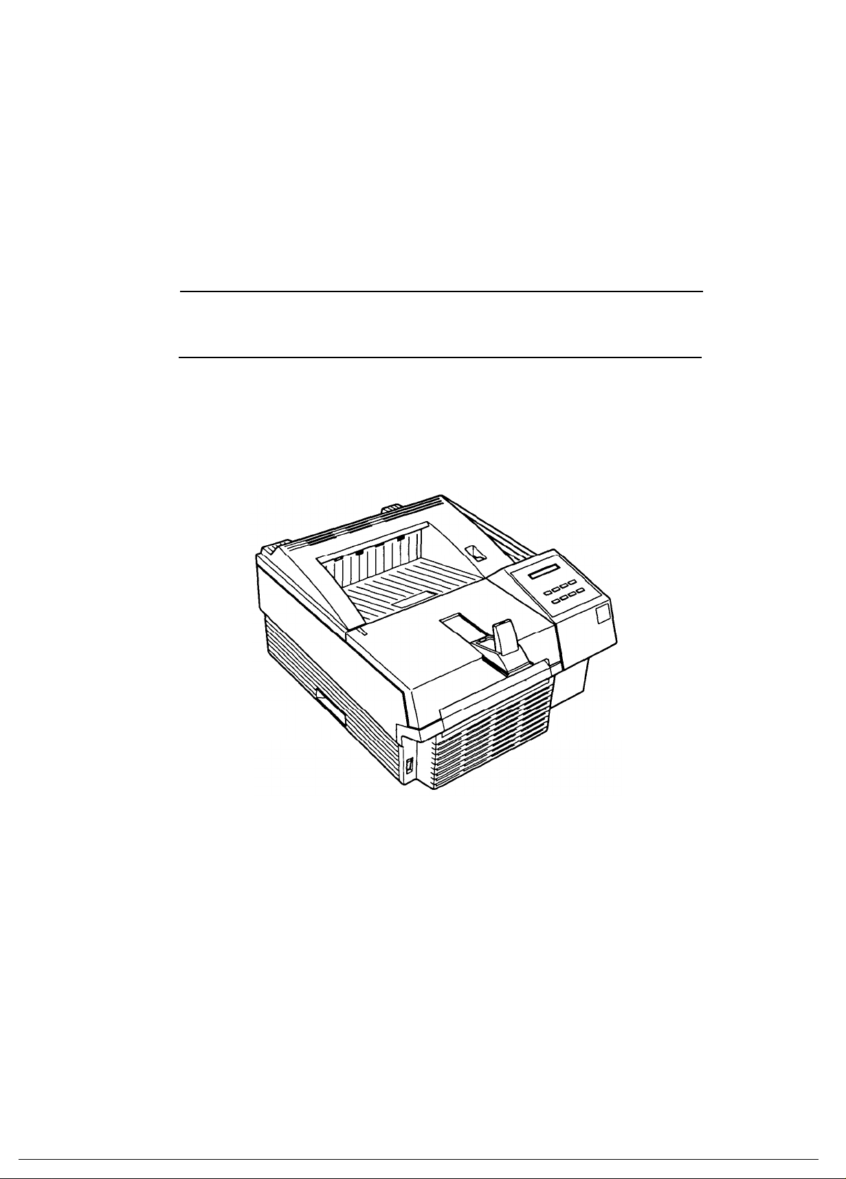
Figure 1-1 shows an exterior view of the EPL-N1200.
Figure 1-1. EPL-N1200 Exterior View
Rev. A 1-1
Page 14

General Description EPL-N1200 Service Manual
Table 1-1 lists optional units available for the EPL-N1200.
Table 1-1. EPL-N1200 Options
Cat. No. Description Note
Supports EPSONScript Level 2 ROM
C83219✽ EPSONScript Level 2 ROM Module
— 72-pin RAM SIMM memory modules For IBM PC compatibles
C81262✽ 500 sheet lower paper cassette A4 Lower paper cassette
C812631 500 sheet lower paper cassette Letter Lower paper cassette
S051016 Imaging cartridge Toner cartridge
C82334✽ LocalTalk
/ Serial Module —
C83620✽ RS-232C intrerface cable (9 pin) For C82334✽
C83619✽ RS-232C intrerface cable (25 pin) For C82334✽
C83618✽ Current loop cable For C82334✽
C82307✽/
C82308✽
C82310✽/
C82311
C82312✽ LocalTalk
32 KB serial interface card —
32 KB parallel interface card —
interface card —
C82314✽ COAX interface card —
C82315✽ TWINAX interface card —
C82323✽ GPIB interface card —
C82331✽
Ethernet interface card for
NetWare
Note: The LocalTalk card (C82312✽) cannot be used with LocalTalk setting on the
LocalTalk/Serial I/F module (C82355✽).
mode (PostScript Level 2 compatible)
fonts and commands
å
1-2 Rev. A
Page 15

EPL-N1200 Service Manual General Description
1.2 SPECIFICATIONS
This section provides statistical data for the EPL-N1200.
1.2.1 Basic Specifications
Print method: Laser beam scanning and dry electro-photography
Resolution: 600 DPI
Printing speed: 12 PPM (letter/A4)
First print time (A4/LT): Less than 16 seconds (A4/Letter; at Polygon-motor stop)
(Warm-up time must be added in above value at standby mode)
Warm-up time:
Paper supply: See Table 1-2.
60 seconds (at rated current and 23° C (73° F) temperature)
Table 1-2. Paper Feed Methods
Paper Supply Capacity Paper Size
A5, B5, A4, LT, GLT,
250*3)
Standard paper tray
EXE, LGL, GLG, F4,
HL, Custom
Monarch, DL, C5,
10 (Envelope)
C6, International B5,
Commercial-10
Lower paper cassette
(optional)*1)
*1:Two units maximum can be mounted.
*2:Paper size is fixed either A4 or Letter.
2
*3:70g/m
*4:When you set pieces of paper on standard paper tray.
*5:When you set a piece of paper on standard paper tray.
*6) It can be used as manual feeding paper slot.
Note 1:
(20lb.)paper
The weight in pounds (lb.) is determined by how much 500 sheets cut to 17 × 22
inch would weigh; 1 g/m
500*3) A4 or LT*2)
2
= 0.2659763 lb.
16 to 24 lb.*4)
(60 to 90 g/m
16 to 41.8 lb.*5)
(60 to 157 g/m
Envelopes made of 16
to 24 lb. (60 to 90 g/m
paper
16 to 24 lb.
(60 to 90 g/m
Note 2: Paper size range: width 3.62 to 8.5 inches (92 to 216 mm)
length 5.83 to 14.0 inches (148 to 356 mm)
Paper types: See Table 1-3.
Usable Thickness
(Ream Weight)
2
)
2
)
2
)
2
)
Table 1-3. Paper Types
Standard paper
Xerox
20 lb. (75 g/m
Regular photocopier paper,
Normal paper
Bond paper,
Recycled paper,
16 to 24 lb. (60 to 90 g/m
Card stock (90 to 157 g/m
Special papers
Envelopes, Labels,Letterhead,
Transparency (OHP) sheets,
Colored paper
Rev. A 1-3
4024 DP paper
2
)
2
)
2
),
Page 16

General Description EPL-N1200 Service Manual
Usability of special papers: See Table 1-4.
Table 1-4. of Special Papers Usability
Input Output OHP Envelopes Labels Card Stock Letterhead
Standard
built-in paper
tray
Lower paper
cassette
R: Reliable feeding and good image quality.
P: Possible, but better avoided.
N: Not supported.
Face down P P P P R
Face down N N N N P
Paper feed alignment and direction:
Paper ejection: Face down
Output tray capacity: 250 sheets (standard paper ; 20 lb. (75g/m
Printable area (standard paper): See Figure 1-2.
Note: The actual printable area depends on the printer mode.
Harmonic noise:
Ozone density: Less than 0.02 PPM
Toxicity: No toxicity exists in organic photo-conductor (OPC), toner,
Center alignment for all sizes
Less than 36 dB(A) standby
Less than 52 dB(A) operating
and plastic materials
2
))
4.00mm
Printable Area
4.00mm
4.00mm4.00mm
Figure 1-2. Printable Area
1-4 Rev. A
Page 17

EPL-N1200 Service Manual General Description
1.2.2 Electrical Specifications
Table 1-5. Electrical Specifications
Description 100 V Version 230 V Version
Rated voltage
Rated frequency range
Input frequency range
Power consumption Less than 700 W Less than 800 W
Power consumption in
non-standby mode
Power consumption in
standby mode
(Heater lamp is off.)
100 ∼ 120 VAC
50 ∼ 60 Hz
47 ∼ 63 Hz
Less than 150 W (Average)
Less than 30 W
(without any optionals installed)
230 VAC
1.2.3 Reliability Specifications
MPBF (Mean Prints Between Failures): Over 50,000 sheets
Note: MPBF indicates average number of pages printed before an occurrence of a problem
requiring replacement or service.
MTBF (Mean Time Between Failures): 3000 Power on hours (more than 10 months)
Jam rate: 1 out of 2,000 sheets or less (excluding multiple-sheet feeding)
Feed failure: 1 out of 2,000sheets or less (excluding multiple-sheet feeding)
Multiple-sheet feeding: 1 out of 500 sheets or less
Paper curl height: 30 mm (1.2 inches) or less (Standard paper)
30 mm (1.2 inches) or less (OHP sheet)
Leading edge bending (1 cm or more): 1 out of 1,000sheets
MTTR (Mean Time To Repair): 30 minutes or less
Durability: 5 years or 300,000 sheets
1.2.4 Environmental Conditions for Operating (Including Imaging Cartridge)
Temperature:
Humidity: 15 to 85% RH
Altitude: 2,500m (8,200 feet) or lower
Levelness: 1 degree or less (front to rear,right to left)
Illuminance: 3,000 lux or less (must not be exposed to direct sunlight)
Surrounding space: Printer should have at least 100mm of clearance on sides
10 to 35°C (50 to 95°F)
and rear.
1.2.5 Environmental Conditions for Storage and Transportation
(Excluding Imaging Cartridge)
Temperature:
Humidity: 30 to 85% RH overfull storage period
Drop test: Clear to JISZ0200-1987 Level1
Vibration: Vibration frequency 5 to 100Hz and 100 to 5Hz
Resistance to atmospheric pressure: 61.3 to 101.3 KPa
Storage period: 18 months (after date of manufacture)
0to35°C (32 to 95°F) overfull storage period
Sweep time10 minutes
Acceleration1G
Acceleration direction 3 directions
Acceleration time180 minutes(60 minutes for ach
direction X, Y, Z)
Rev. A 1-5
Page 18

General Description EPL-N1200 Service Manual
1.2.6 Applicable Standards (without any electrical optional unit)
Safety Standards
120 VAC model: UL 1950 Deviation 3, CSA 22.2 No.950 Deviation 3
230 VAC model (Europe): EN 60950 (IEC950), NEMKO (IEC950),
CE marking (low voltage directive)
Safety Regulations (Laser Radiation)
120 VAC model: FDA (NCDRH) Class 1
230 VAC model (Europe): VDE 0837 (Laser Class 1)(IEC825)
EMI
120 VAC model: FCC Part 15 Subpart B Class B, DOC Class B
230 VAC model (Europe): Vfg 243 (VDE 0878 Part 3,30),
EN55022 class B (CISPR Pub.22 class B),
CE marking (EMC directive)
230 VAC model (Pacific): AS/NZS 3548
Others
Toner: No effect on human health (OSHA, TSCA, EINECS)
OPC: No effect on human health (OSHA)
Ozone: Less than 0.02 PPM
other UL478 (5th edition)
Materials: SWISS Environmental Law (No CdS must be contained)
Power Consumption Applies to International Energy Star Program standard
1.2.7 Specification for Consumable (Imaging Cartridge)
Life: 6,000 pages
Note: In continuous print mode with A4/letter paper at a 5% image (black/white ratio) ratio. L
life varies, depending on print mode (continuous or intermittent) and/or image ratio.
Environmental Conditions for Storage and Transportation
Temperature:
Humidity: 30 to 85% RH over full storage period
Drop test: Height 76 cm (30.4 inches): 1 corner, 3 edges, 6 sides
Vibration: Same as printer
Resistance to atmospheric pressure: Same as printer
Storage period: 18 months after date of manufacture
0to30°C(32 to 86°F) overfull storage period
1.2.8 Physical Specifications
Dimensions (Width × Depth × Height):
Printer: 411 × 484 × 265 mm (16.2 × 19.0 × 10.4 inches)
With one lower cassette: 411 × 484 × 365 mm (16.2 × 19.0 × 14.4 inches)
With two lower cassettes: 411 × 484 × 466 mm (16.2 × 19.0 × 18.3 inches)
Weight: Approx. 15 Kg (33.1 lb.)
(including imaging cartridge, excluding optional unit)
1-6 Rev. A
Page 19
EPL-N1200 Service Manual General Description
1.2.9 Software Specifications
Built-in modes: HP LaserJet4 emulation ( PCL
EPSON GL/2 mode (LJ4-GL/2 mode and GL-like mode)
FX (FX-870/1170,LX-100) emulation mode
ESC/P2 (Stylus800/1000) mode
I239X ( IBM 2390/2391 Plus emulation)
EPSON PostScript Level 2 (Option)
Note: The EPSON GL/2 mode is similar to the GL/2 mode included in the HP LaserJet 4
emulation. Table 1-6 shows the differences between EPSON GL/2 mode and the GL/2
mode in the HP LaserJet 4 emulation. While in EPSON GL/2 mode, the operator can
enter GL/2 mode without sending the ESC %#B (Enter GL/2 mode) command. If the
operator’s application software cannot send the ESC %#B command, then use this mode.
5e)
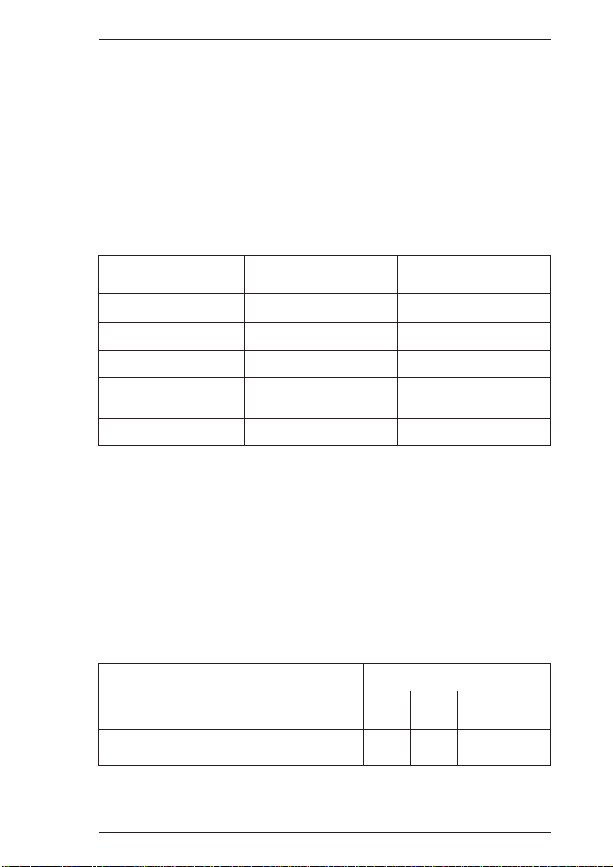
Table 1-6. Differences between EPSON GL/2 and
GL/2 in the HP LaserJet 4 Emulation
EPSON GL/2 Mode
PCL mode Does not exist Exists as the initial mode
Paper eject Supports PG, AF commands Supported in PCL
Auto eject SelecType setting Not available
Reduced printing SelecType setting Available in PCL
Switch to PCL
(ESC %#A)
Reset (ESC E) Ejects paper and then initializes
PJL, EJL, and ES Supported Supported
Advance Full Page
(PG, AF)
Notes: EPSON GL/2 mode has two operational modes. One is LJ4-GL/2 mode; the other is the
GL-like mode.
LJ4-GL/2 mode emulates the GL/2 mode in the HP LaserJet 4 emulation. The user can
print with software that supports the HP 7600 series plotter.
The GL-like mode features all the commands of the LJ4-GL/2 mode, plus a few additional
commands. The GL-like mode emulates some of the HP-GL
commands. If the application software uses unsupported commands for the GL-like
mode, print cannot be assured.
Optional modes:
EPSON Script Level 2(PostScript Level 2 emulation) mode
Not supported Supported
Supported Not supported
GL/2 for HP LaserJet 4
Emulation Mode
Ejects paper, switches to PCL,
and then initializes
plotter (HP 7475A, etc.)
Auxiliary software: Hexdump
Status sheet
Font sample
Built-in fonts: SeeTable1-7.
Table 1-7. Built-in Fonts (Bitmap Fonts)
Applicable Mode
Resident Fonts
Line Printer 16.66 CPI (Portrait)
OCR B 10 CPI (Portrait)
V: Supported, -: Not Supported
Rev. A 1-7
HP LJ4
GL/2
ESC/P 2 FX I239X
V--
-VV
V
Page 20

General Description EPL-N1200 Service Manual
Table 1-7. Built-in Fonts (Scalable Fonts)
Applicable Mode
Resident Fonts
HP LJ4
GL/2
ESC/P 2 FX I239X
EPSON Roman - V V EPSON Sans serif - V V V
EPSON Prestige - V V V
EPSON Script - V V V
EPSON Gothic - - - V
EPSON Presentor - - - V
EPSON Orator - - - V
Dutch
801 Roman SWC V - - Dutch 801 Bold SWC V - - Dutch 801 Italic SWC V - - Dutch 801 Bold Italic SWC V - - Zapf Humanist 601 Demi SWC V - - Zapf Humanist 601 Bold SWC V - - Zapf Humanist 601 Demi Italic SWC V - - Zapf Humanist 601 Bold Italic SWC V - - Ribbon 131 SWC V - - Clarendon Condensed SWC V - - -
Swiss
742 SWC V - - Swiss 742 Bold SWC V - - Swiss 742 Medium Italic SWC V - - Swiss 742 Bold Italic SWC V - - Swiss 742 Condensed SWC V - - Swiss 742 Bold Condensed SWC V - - Swiss 742 Condensed Italic SWC V - - Swiss 742 Bold Italic Condensed SWC V - - Incised 901 SWC V - - Incised 901 Black SWC V - - Incised 901 Italic SWC V - - Original Garamond SWC V - - Original Garamond Bold SWC V - - Original Garamond Italic SWC V - - Original Garamond Bold Italic SWC V - - Audrey Two SWC V - - Flareserif 821 SWC V - - Flareserif 821 Extra Bold V - - Swiss 721 Roman SWM V V - Swiss 721 Bold SWM V V - Swiss 721 Oblique SWM V - - Swiss 721 Bold Oblique SWM V - - Dutch 801 Roman SWM V V - Dutch 801 Bold SWM V V - Dutch 801 Italic SWM V - - Dutch 801 Bold Italic SWM V - - Symbol Set SWA V - - More WingBats SWM V - - -
V: Supported, -: Not Supported
1-8 Rev. A
Page 21

EPL-N1200 Service Manual General Description
Table 1-7. Built-in Fonts (Scalable Fonts;Cont’)
Applicable Mode
Resident Fonts
HP LJ4, GL/2 ESC/P 2 FX I239X
Courier SWC V V V V
Courier Bold SWC V V V V
Courier Italic SWC V - - Courier Bold Italic SWC V - - Letter Gothic Roman SWC V V V Letter Gothic Bold SWC V V V Letter Gothic Italic SWC V - - Ext. Graph - V V V
V: Supported, -: Not supported
Rev. A 1-9
Page 22

General Description EPL-N1200 Service Manual
Font Symbol Sets and Character Tables
HP LaserJet 4 Mode (bitmap fonts) : 28 symbol sets
Roman-8 Norweg1 Roman Extension French
HP German ItalianT JIS ASCII ECM94-1
Swedis2 ANSI ASCII Norweg2 UK
French2 German HP Spanish Legal
Chinese 8859-2 ISO Spanish IRV
Swedish Portuguese 8859-9 ISO IBM Portuguese
IBM Spanish IBM
HP LaserJet4 Mode (scalable fonts) :45 symbol sets
Roman-8 Norweg1 Roman Extension French
HP German Italian JIS ASCII ECM94-1
Swedis2 ANSI ASCII Norweg2 UK
French2 German HP Spanish Legal
Chinese 8859-2 ISO Spanish IRV
Swedish Portuguese PsMath 8859-9 ISO
IBM Portuguese WiTurkish DeskTop Math-8WiE.Europe
PcTk437 Windows PsText IBM-US
IBM-DN McText PcMultilingual VeInternational
VeUS PiFont PcE.Europe Symbol
WiAnsi TWingdings MsPublishing VeMathRIBM SPanish
-US IBM-DN PcMultilingual
ESC/P 2 Mode : 15 International characters and 9 code tables
USA SPAIN1 FRANCE JAPAN
GERMANY NORWAY UK DENMARK2
DENMARK1 SPAIN2 SWEDEN L.AMERICA
ITALY KOREA TLEGAL
PcUSA(437) PcMultilingual(850) TPcPortuguese(860)
TPcCanFrench(863) PcNordic(865) T PcTurk2(857)
PcE.Europe(852) BpBRASCII BpAbicomp
FX Mode : 13 International characters and 9 code tables
USA SPAIN1 FRANCE JAPAN
GERMANY NORWAY UK DENMARK2
DENMARK1 SPAIN2 SWEDENT L.AMERICA
ITALY
PcUSA(437) PcMultilingual(850) TPcPortuguese(860)
PcCanFrench(863) PcNordic(865) PcTurk2(857)
PcE.Europe(852) BpBRASCII T BpAbicomp
I239X Mode : 5 code tables
PcUSA(437) PcMultilingual(850)
RPcPortuguese(860) PcCanFrench(863)
PcNordic(865)
1-10 Rev. A
Page 23

EPL-N1200 Service Manual General Description
1.2.10 Lower Paper Cassette (Option) Specifications
Paper Size: A4 or Letter
2
Paper Weight: 60 to 90 g/m
Print Speed: 12 PPM (letter/A4)
(16 to 24 lb)
Paper Feed: Automatic feed delivery system. Cassette capacity up to 500 sheets
(75 g/m
2
or 20 lb paper)
Feeding Speed (first print): First Lower Paper Cassette:
16 seconds or less; (A4 or letter)
Second Lower Paper Cassette
16 seconds or less; (A4 or letter)
Feeding Speed
12 PPM (A4/Letter)
(subsequent sheets)
Paper Type: Plain paper, such as copier paper
Power Supply: 5 V DCand 24 VDC are supplied by the printer
Dimensions and Weight:
(Width × Depth × Height)
Lower paper cassette entire housing;
405 × 477 × 107 mm (18.8 × 19.0 × 4.2 inches)
2.8 Kg (6.2 lb.)
Paper Cassette;
252 × 318 × 82 mm (9.9 × 12.5 × 3.2 inches)
1.1 Kg (2.4 lb.)
Harmonic noise: Less than 52 dB(A) (operating)
Rev. A 1-11
Page 24
General Description EPL-N1200 Service Manual
1.3 INTERFACE SPECIFICATIONS
The EPL-N1200 is equipped with the following external interfaces:
■ Parallel interface B
■ Parallel interface C
■ Serial interface on optional LocalTalk/Serial module
■ LocalTalk interface on optional LocalTalk/Serial module
1.3.1 Parallel Interfaces
There are two parallel interfaces: parallel interface B and parallel interface C. Each interface has
his own connector.
Parallel Interface B
Interface specification complies with IEEE 1284-I.
Operating modes:
Compatibility (standard) and nibble (reverse) modes
Transfer speed: APPROX. 400 KB/second (MAX.)
Connector type: Amphenol or equivalent (IEEE 1284B - type connector)
Parallel Interface C
Interface specification complies with IEEE 1284-II.
Operating modes:
Compatibility (standard), nibble (reverse), and ECP modes
Transfer speed: APPROX. 2MB/second in ECP mode (MAX.)
Connector type: IEEE 1284C - type connector
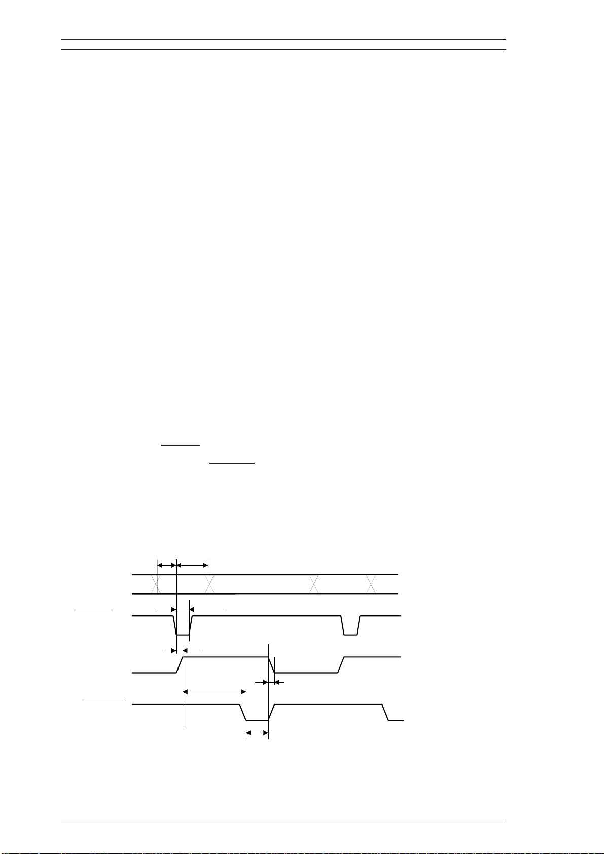
1.3.1.1 Compatibility (Standard) Mode
System: STROBE synchronization, 8-bit parallel data transfer
Handshaking: BUSY andACKNLG signals
Applicable plug: 57-30360 (Amphenol or equivalent)
Signal timing: See Figure 1-3.
Signal description: See Table 1-8.
0.5
(minimum)
s
µ
0.5
s
µ
(minimum)
DATA 1-8
STROBE
0.5
BUSY
ACKNLG
s (maximum)
µ
VALID
0.5 or 5
0.5
s (minimum)
µ
s
(minimum)
µ
0 s
(min.)
1 or 10
(typical)
VALID
s
µ
Figure 1-3. Compatibility Mode Signal Timing
1-12 Rev. A
Page 25
EPL-N1200 Service Manual General Description
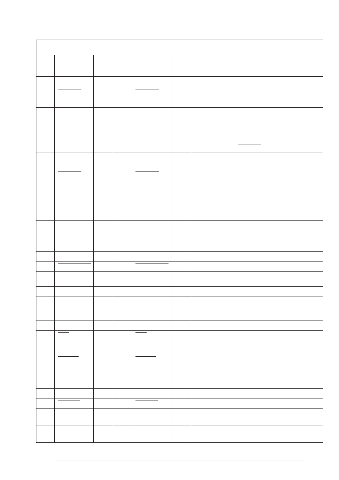
Table 1-8. Parallel Interfaces Pin Assignment
Parallel-B Parallel-C
Pin
Signal Name I/O
No.
STROBE I 15 STROBE I
1
2-9 DATA 1-8 I 6-13 DATA 1-8 I/O
ACKNLG O 3 ACKNLG O
10
11 BUSY O 1 BUSY O
Pin
No.
Signal Name I/O
Description
STROBE is a strobe pulse used to read data from
the host computer. The pulse width must be more
than 0.5 µsec. Normally it is HIGH, and data is
latched at the trailing edge of this signal.
DATA 1 to 8 are parallel data bits. When the signal
is HIGH, the data bit is 1, and when it is LOW, the
data bit is 0.
The most significant bit (MSB) is DATA8. The
signal state must be maintained for 0.5 µsec. on
either side of the
ACKNLG is an acknowledge pulse with an
approximate width of 1 or 10 µsec. This signal
goes LOW when the data reception is completed,
which indicates that the printer can accept new
data. Timing with the BUSY signal is specified
through SelecType.
The BUSY signal informs the host computer of the
printer state. When the signal is HIGH, the printer
cannot accept data.
STROBE signal active edge.
The PE signal indicates paper empty for the
12 PE O 5 PE O
13 SLCT O 2 SLCT O
AUTO-FEED I 17 AUTO-FEED I Not used.
14
15,18,
19-30 GND - 19-35 GND - Ground level for the twisted pair return signal.
NC - - - - Not used.
34
16 GND - - - -
CHASSIS
17
GND
INIT I 14 INIT I
31
32
ERROR O 4 ERROR O
33 GND
---
---
standard tray selected through SelecType or
command, or for the optional paper cassette.
Paper empty is indicated by HIGH.
Use at reverse mode.
Logic ground level.
Connected to the printer chassis. The printer
-
chassis GND and the signal GND are connected
to each other.
The STROBE signal is ignored when this signal is
LOW.
This level goes LOW when the printer is:
out of paper
paper jam
in error state
off line
- Same as for pins 19 to 30.
35 +5 - - - - Pulled up to +5V through 1.0 Kohm resistance.
SLCT IN - 16 SLCT IN I
36
-- - 18
--
Rev. A 1-13
-36
Host Logic
High
Peripheral
Logic High
Use the reverse mode.
Hosyt logic high signal
I
O Peripheral logic high signal
Page 26
General Description EPL-N1200 Service Manual
1.3.1.2 Nibble (Reverse), ECP Mode
The reverse mode for EPL-N1200 supports the IEEE-P1284 nibble mode. This printer can run in
reverse mode, in which the printer can inform the computer of its status by EJL and PJL commands.
System:
Connector type: P90-25027-1 (Amphenol) receptacle
Applicable plug: 57-30360( Amphenol or equivalent)
Signal description: See Table 1-9.
Nibble mode of IEEE-P1284
Table 1-9. Parallel Interface Pin Assignment
Pin No. Signal Name I/O Description
1
2-9 DATA 1-8 IN
10
11 BUSY OUT
12 PE OUT
13 SLCT OUT
STROBE IN
ACKNLG OUT
HostClk: This signal is a strobe pulse used to read extension
request values from the host computer during negotiation.
The signals are data bits of extension request values during
negotiation. This printer supports following values:
0000 0100: Request Device ID (by nibble mode sending)
0000 0000: Request nibble mode
PtrClk: Printer data sending clock.
PtrBusy: Printer sending data bits 3 and 7 during data transfer
to host computer.
AckDataReq: Printer sending data bits 2 and 6 during data
transfer to host computer.
Xflag: Printer sending data bits 2 and 6 during data transfer to
host computer.
HostBusy: This signal informs the printer of the host computer
14
15 NC 16 GND -
17 CHASSIS GND 18 NC - Not connected.
19-30 GND -
31
32
33 GND -
34 NC 35 +5 - Pulled up to +5V through 1.0 Kohm resistance.
36
AUTO-FEED IN
INIT IN nInit: High level fixed
ERROR OUT
SLCT IN IN
state. When the signal is HIGH, the host computer cannot
accept data.
Not used.
Logic ground level.
Connected to the printer chassis. The printer chassis GND
and the signal GND are connected to each other.
Ground level for the twisted pair return signal.
nDataAvail: Printer sending data bits 0 and 4 during data
transfer to host computer.
Same as for pins 19 to 30.
Not used.
1284Active: If this signal is set to HIGH, this printer active
P1284 (reverse mode).
1-14 Rev. A
Page 27
EPL-N1200 Service Manual General Description
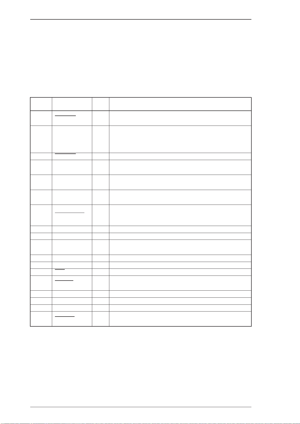
Compatibility Mode
Forward
Data
Transfer
No data sent
Host Busy
Data Not
Available
STROBE
ACK and BUSY
ERR=HIGH
ERR=HIGH
No data sent
Forward
Idle
SLCT IN=HIGH
Negotiation
Reverse
Data
Transfer
Failed
Negotiation
Sending data
ERR=LOW
Sending data
AUTO
FEED=LOW
Request to
send data
Terminate
SLCT IN=LOW
ERR=LOW
Host Busy
Data
Available
AUTO
FEED=LOW
Reverse
ERR=LOW
Idle
Figure 1-4. Parallel Interface State Switch Diagram
Figure 1-4 shows the parallel interface state switch diagram.
AUTO
FEED=HIGH
Interrupt
Host
Rev. A 1-15
Page 28
(
)
(
)
General Description EPL-N1200 Service Manual
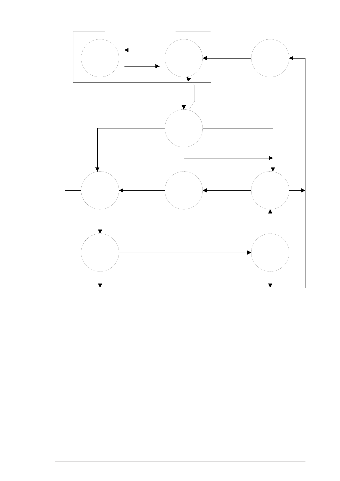
Figure 1-5 shows the timing chart for negotiation.
DATA
SEL-IN
STROBE
AUTO-FEED
ACKNLG
BUSY
ERROR
Peripheral Busy Status
Current Peripheral StatusPE
Current Peripheral Status
Compatibility
00h or 04h
Negotiation
Note1
Note 2SLCT
Note1
HB DA or
HB DNA
Note 3
Figure 1-5. Negotiation Timing Chart
Note 1: The signal is set to HIGH when not sending data.
The signal is set to LOW when sending data.
Note 2: The signal is set to HIGH, if extension request value was 04h.
Note 3: HB DA: Host Busy Data Available
HB DNA: Host Busy Data Not Available
Idle or
Transfer
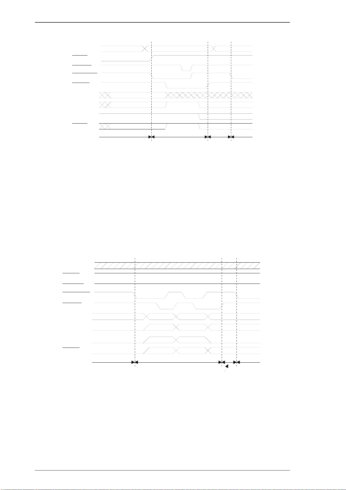
Figure 1-6 shows the timing chart for data transfer.
DATA
SEL-IN
STROBE
AUTO-FEED
ACKNLG
Peripheral Busy StatusBUSY
PE
SLCT
ERROR
HB DA Negotiation
Bit 3 Bit 7
Bit 2 Bit 6
Bit 1 Bit 5
Bit 0 Bit 4
Figure 1-6. Data Transfer Timing Chart
Peripheral Busy Status
Note 1
Note 2
Note 1
Idle or
Transfer
HB DA or
HB DNA
Note 3
Note 1: The signal is set to HIGH when not sending data.
The signal is set to LOW when sending data.
Note 2: The signal is set to HIGH, if extension request value was 04h.
Note 3: HB DA: Host Busy Data Available
HB DNA: Host Busy Data Not Available
1-16 Rev. A
Page 29
A
A
EPL-N1200 Service Manual General Description
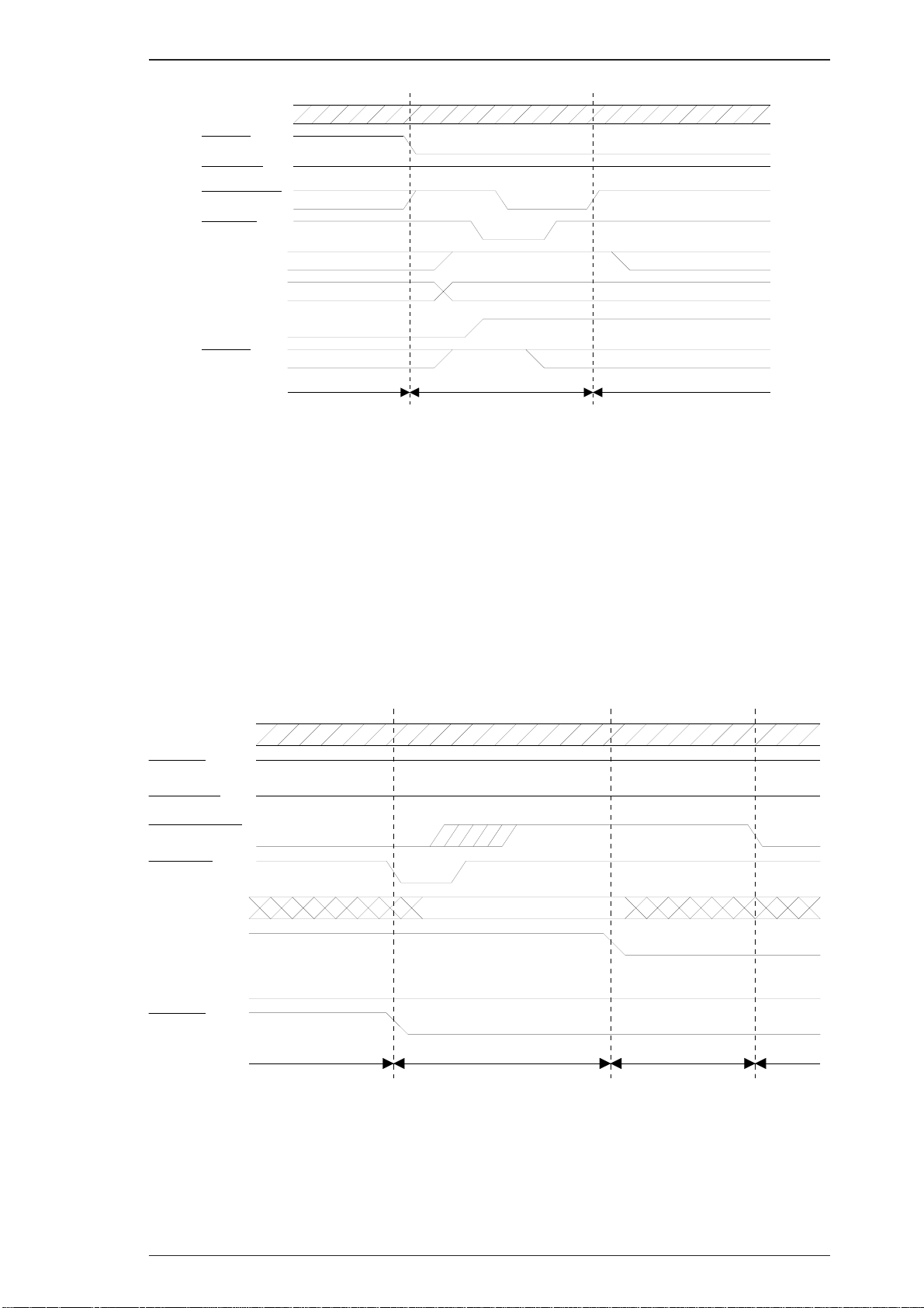
DATA
SEL-IN
STROBE
AUTO-FEED
ACKNLG
Note 3
Peripheral Busy StatusBUSY
PE
SLCT
ERROR
Note 1
Note 2
HB DNA, Idle,
or HB DA
Termination Compatibility
Current Peripheral Status
Current Peripheral StatusNote 1
Figure 1-7. Termination Timing Chart
Figure 1-7 shows the timing chart of termination.
Note 1: The signal is HIGH when HB DNA.
The signal is LOW when HB DA.
Note 2: The signal is set to HIGH, if extension request value was 04h.
Note 3: Idle = LOW
Figure 1-8 shows the timing chart for an interrupt.
Peripheral Busy Status
DATA
SEL-IN
STROBE
UTO-FEED
CKNLG
Peripheral Busy StatusBUSY
PE
SLCT
Note 1
ERROR
Reverse Idle Interrupt
HB DA Transfer
Figure 1-8. Interrupt Timing Chart
Note : The signal is set to HIGH, if extension request value was 04h.
Rev. A 1-17
Page 30

General Description EPL-N1200 Service Manual
1.3.2 Optional Serial Interface (LocalTalk/Serial Module)
The optional LocalTalk/Serial module contains serial interface with the following characteristics.
Type: RS-232C or current loop
Transfer system: Full duplex
Synchronization: Asynchronous start-stop system
Start-bit: 1 bit
Stop-bit: 1 or 2 bits
Data length: 7 bits or 8 bits
Parity: Odd, even, or none
Protocol: X-ON/X-OFF (can be combined with DTR control)
DTR control (can be combined with X-ON/X-OFF)
Transfer speed: 300, 600, 1200, 2400, 4800, 9600, 19200, 38400, or 57600 BPS
Note 1: For RS-232C signal level, speeds of 38400 BPS and above place restrictions on the host
computer, cable, and other operating conditions.
Note 2 For current loop signal level, speeds of 2400 BPS and above place restrictions on the
host computer, cable, and other operationg conditions.
Error: Overrun error: Processed as missing data and replaced by “*”
Parity error: Replaced by “*”
Framing error: Replaced by “*”
Breaking character: Ignored
Applicable plug Circular miniature DIN 8-pin plug
Signal Level
(EIA BASED) :
Note : Annotations “MIN”. and “MAX.” apply to absolute values.
Signal descriptions: See Table 1-10.
TXD, DTR
Out put Voltage (VOH) 5 to 15 V
(VOL) -5 to -15 V
Open circuit voltage (VO) within
Impedance with power off (rO) 300 ohms (MIN.)
Load capacitance (CL) 2500 pF (MAX.)
Through rate 30 V/u SEC (MAX.)
Load resistance (Lo) 3 K to 7 K ohms
RXD, CTS
Input Voltage (VIH) 3 V (MIN.)
(VIL) -5 V (MIN.)*1)
Input signal range +25 V (MAX.)*1)
Input impedance (RI) 3 K to 7 K ohms
Imput current (II) + 8 mA (MAX)*1)
Open-circuit input voltage (EL) -2 V (MAX>)*1)
+15 V
1-18 Rev. A
Page 31

EPL-N1200 Service Manual General Description
Table 1-10. Serial Interface Pin Assignments
Pin No.
^
1
2
3
4
RS-232C Current Loop
Signal Name I/O Signal Name I/O ^
DTR O N.C. -
CTS I N.C. - Always ignored.
TXD O
GND - GND - Ground.
TTY-TXD
return
Description
Signal output by the printer. When the DTR
signals HIGH, the RXD signal can be
received by the printer. The SelecType
setting doesn’t specify DTR control, the
signal level is HIGH while the printer power is
on. When SelecType setting is used for DTR
control, DTR goes LOW in case of any error
conditions.
The data (RXD) from host computer must be
stopped within 256 characters after DTR
goes LOW.
TXD:
Serial ASCII data output from the printer.
It maintains “MARK” state (LOW level)
between transmitted character codes.
-
Logic 0 is at HIGH level (“SPACE”) and logic
1 is at LOW level (“MARK”).
TTY-TXD return:
Refer to TTY-TXD.
RXD:
Serial ASCII data input to the printer. It
5
6
7
8
RXD I
N.C. - TTY-TXD O
N.C. - N.C. - Not connected.
N.C. I TTY-RXD I
TTY-RXD
return
maintains “MARK” state (“LOW level)
-
between received character codes.
TTY-TXD return:
Refer to TTX-RXD.
TTY-TXD:
Serial ASCII data output from the printer.
The logic is determined by the impedance
between pins 3 and 6.
Logic 0 is high impedance (“SPACE”) at
current off and logic 1 is low impedance
(“MARK”) at current on.
It maintains “MARK” state (LOW level)
between transmitted character codes
TTY-RXD:
Serial ASCII data input to the printer.
The logic is determined by the impedance
between pins 5 and 8.
Logic 0 is high impedance (“SPACE”) when
current is off and logic 1 is low impedance
(“MARK”) when current is on.
It maintains “MARK” state (LOW level)
between transmitted character codes
Rev. A 1-19
Page 32

General Description EPL-N1200 Service Manual
Handshaking
When the vacant area for data in the input buffer drops to 256 bytes, the printer outputs an X-OFF
code or sets the DTR signal level to LOW, indicating that the printer cannot receive more data.
Once the vacant area for data in the buffer recovers to 512 bytes, the printer outputs an X-ON code
or sets the DTR flag to HIGH, indicating that the printer is again ready to receive data.
Protocol
There are two types of protocols, as listed below, and each of them can be designated by
SelecType independently.
o DTR/DSR protocol
SelecType is used to execute the DTR/DSR control protocol. The DTR signal is set to HIGH when
the printer is ready to receive data, and to LOW when conditions indicate an error or that the
receiving buffer is full.
When the error is cleared and the printer returns to on-line mode, the signal returns to HIGH. When
SelecType is used to set the DTR control OFF, DTR is always set HIGH. The printer transmits TXD
only when DSR is at the HIGH level (DSR is always considered HIGH when the SelecType setting
for DSR is OFF). X-ON/X-OFF transmission is independent of the DSR state.
o X-ON/X-OFF (DC1/DC3) protocol
SelecType is used to execute the X-ON/X-OFF protocol. The X-OFF (DC3) code is output if status
indicates an error, and the printer warns the host to stop data transmission within 256 characters.
No further X-OFF codes are sent in response to additional data received from the host after the
X-OFF code has been sent once. The X-ON (DC1) code is output after all conditions given in the
error are cleared.
When the remaining capacity of the receive buffer reaches 512 characters, X-OFF (DC3) is output
once. It is sent only once, even if there are multiple errors. The printer goes on line automatically at
power on, and outputs an X-ON code. Transmission of X-ON/X-OFF codes can be defined by
SelecType.
1-20 Rev. A
Page 33

EPL-N1200 Service Manual General Description
1.3.3 Optional LocalTalk Interface (LocalTalk/Serial Module)
The optional LocalTalk/Serial module contains LocalTalk interface with the following characteristics.
Type: LocalTalk
Signal level: Same as RS-422 signal level
Protocol: X-ON/X-OFF (cannot be combined with DTR control)
DTR control (cannot be combined with X-ON/X-OFF)
Transfer speed: 230.4 K BPS
Signal description: See Table 1-11.
Table 1-11. LocalTalk Interface Pin Assignments
Pin No.
1
2
3
4
5
6
7
8
Signal Name I/O Description
DTR O
CTS I The printer transmits the data through TXD while CTS is HIGH.
TXD- O
GND - Ground.
RXD- I
TXD+ O Refer to TXD-.
N.C. - Not connected.
RXD+ I Refer to RXD-.
Signal output by the printer. When the DTR signals HIGH, the RXD
signal can be received by the printer.
Serial ASCII data output from the printer.
HIGH level: when SD+ voltage is higher than SD- voltage.
LOW level: when SD+ voltage is less than SD- voltage.
Logic 0 “SPACE” and logic 1 “MARK” must be maintained between
transmitted character codes.
Serial ASCII data input from computer.
HIGH level: when RD+ voltage is higher than RD- voltage.
LOW level: when RD+ voltage is less than RD- voltage.
Logic 0 “SPACE” and logic 1 “MARK” must be maintained between
transmitted character codes.
Rev. A 1-21
Page 34

EPL-N1200 Service Manual General Description
Buttons
o On Line Switches the printer between on-line and off-line modes. While in
SelecType mode, this button exits SelecType mode.
o Manual Feed
(On Line + ALT)
o Item Enters SelecType mode.
o Page Size
(Item+ ALT)
Enters directly (a short cut) to manual feed; this setting is the same
as the manual setting in the PRINTING Menu of SelecType.
Changes the item in SelecType mode.
Enters directly (a short cut) to the paper size setting for the standard
and optional paper tray in Printing Menu of SelecType.
o Paper Source
(Menu+ ALT)
o ALT Modifies functions of other buttons.
o ↑
o ↓ (↑ + ALT)
o Enter Sets the current option in SelecType.
o Form Feed When the printer is off line and the Form Feed light is lit, pressing
o Continue Pressing this button when the Continue light is flashing clears an
o SelecType Selects one of three modes, OneTouch menu 1, OneTouch menu 2,
o Menu Selects one of three menus, Paper Source, RITech, or SelecType.
o Value Selects one of three menus, Manual Feed, MP Tray Size, or
o Enter Selects one of three menus, Orientation, Toner Save Mode, or
o RESET
(Continue + ALT)
Enters directly (short cut) to the paper tray select setting in
Config Menu of SelecType.
Changes to the next SelecType option.
Changes to the previous SelecType option.
this button prints data in the printer’s memory.
error.
or SelecType mode.
selects item option in SelecType.
defines setting value or executes an operation in SelecType.
Enter to reset operation; LCD displays “Reset”, printing stops, and
the input buffer of current interface is cleared.
If the Continue + ALT buttons aredepressed continuously after
“Reset” displays, the message displayed on the LCD changes to
“Reset ALL” (after about 5 seconds), and the printer enters to
Warming Up" operation; printer clears all RAM.
Rev. A 1-23
Page 35

General Description EPL-N1200 Service Manual
1.4 OPERATING INSTRUCTIONS
This section describes the functions performed through the control panel, such as test print,
hexadecimal dump, and SelecType.
1.4.1 Control Panel
The printer control panel gives you easy control over most common printer operations. The panel
consists of a liquid crystal display (LCD), indicator lights, and buttons.
Figure 1-9. Control Panel
Display (LCD)
A 20-character (5 × 7 dot matrix) by 1-row liquid crystal display (LCD) unit that indicates printer
status. A variety of printer parameters can be displayed and set using SelecType mode.
Indicator lights
o On Line
ON: Communication with the host is possible.
OFF: Communication with the host is not currently possible.
Flashing: This state occurs when the system cannot shift from off line to on line, or vice
versa.
o Form Feed
This LED indicates the data processing condition for each interface channel.
ON: Received data stored in the printer but has not been printed.
OFF: No printable data remains in the printer.
Flashing: The printer is processing data.
o Continue
Flashes when an error is detected or a maintenance procedure is needed. An error message
appears on the display at the same time.
o OneTouch Menu 1
Indicates that OneTouch setting mode is active and OneTouch Menu 1 is in use.
o One Touch Menu 2
Indicates that OneTouch setting mode is active and OneTouch Menu 2 is in use.
o SelecType
Indicates that SelecType setting mode is active.
o All LEDs are flashing
An error has occurred that requires a service call.
1-22 Rev. A
Page 36

General Description EPL-N1200 Service Manual
1.4.2 SelecType Functions
SelecType function on the printer control panel allows the user to control most of the printer’s
functions, such as printing test pages, selecting a paper size, and changing the printer’s
configuration. Enter SelecType mode by pressing the Menu or Item button.
Table 1-12 shows the SelecType options.
Table 1-12. SelecType Functions
Menu
(Changed by Menu
button)
Printing Menu
LJ4 Menu
Item
(Changed by Item button)
Paper Source
Page Size
Orientation Port, Land
Copies 1 to 999
Manual Feed Off, On
Resolution 600, 300
Font Source Resident, SIMM, Download
Font Number 0 to (available; MAX. 65535)
Pitch 0.44 to 10.00 to 99.99 CPI (step 0.01)
Height 4.00 to 12.00 to 999.75 PT. (step 0.25)
SymSet
Auto, MP, LC1*11), LC2*12)
A4*1), A5, B5, LT*3), HLT, LGL, GLT,
GLG, EXE, F4, MON, C10, DL, C5, IB5,
CTM
Roman-8, ECM94-1, 8859-2 ISO, 8859-9
ISO, IBM-US, IBM-DN, PcMultiling,
PcE.Europe, PcTk437, WiAnsi,
WiE.Europe, WiTurkish, DeskTop, PsText,
VeInternati, VeUS, MsPublishin, Math-8,
PsMath, VeMath, PiFont, Legal, UK, ANSI
ASCII, Swedis2, Italian, Spanish, German,
Norweg1, French2, Windows
Available Options
(Changed by ↑ or ↓ button)
(Set by Enter button)
Form 5 to 60*3), to 64*2), to 128 lines
Source SymSet*16) 0 to 277 to 3199
Desrt SymSet*16) 0 to 277 to 3199
PS Menu*4)
ESCP2 Menu
* With option
1-24 Rev. A
Err Sheet Off, On
MicroGray Off
Protect Level 1 to 5
Font
Pitch 10 CPI, 12 CPI, 15 CPI, Prop
Condensed Off, On
T.Margin 0.40 to 0.50 to 1.50 Inch (step 0.05)
Text
Courier, Prestige, Roman, Sans serif,
Roman T, Orator S, Sans H, Script, OCR B
1 to 62*3), to 66*2), to (available; MAX.
81) Lines
Page 37

EPL-N1200 Service Manual General Description
Table 1-12. SelecType Functions (Cont.)
Menu
(Changed by Menu
button)
ESCP2 Menu
(Cont.)
FX Menu
Item
(Changed by Item button)
Italic, PcUSA, PcMultilin, PcPortugues,
CG Table
Country
Auto CR On, Off
Auto LF Off, On
Bit Image Dark, Light, BarCode
Zero Char 0, 0
Font
Pitch 10cpi, 12cpi, 15cpi, Prop
Condensed Off, On
T.Margin 0.40 to 0.50 to 1.50 Inch (step 0.05)
PcCanFrenc, PcNordic, PcTurkish2,
Pc.E.Europe, BpBR ASCII, BpAbicomp
USA, France, Germany, UK, Denmak,
Sweden, Italy, Spain1, Japan, Norway,
Denmark2, Spain2, LatinAmeric, Korea
Courier, Prestige, Roman, Sans serif,
Script, Orator S, OCR B
Available Options
(Changed by ↑ or ↓ button)
(Set by Enter button)
,
I239X Menu
1 to
Text
CG Table
Country
Auto CR On, Off
Auto LF Off,On
Bit Image Dark, Light, BarCode
Zero Char
Font
Pitch 10cpi, 12cpi, 15cpi, 17cpi,20cpi,24cpi, Prop
Code Page 437, 850, 860, 863, 865
T.Margin 0.30 to 0.40 to 1.50 Inch (step 0.05)
Text
62*3) to 66*2) to (Available 81 MAX.)
Lines
Italic,
PcUSA, PcMultilin, PcPortugues,
PcCanFrenc, PcNordic, PcTurkish2,
Pc.E.Europe, BpBRASCII, BpAbicomp
USA, France, Germany, UK, Denmak,
Sweden, Italy, Spain1, Japan, Norway,
Denmark2, Spain2, LatinAmeric
0, φ
Courier, Prestige, Gothic, Orator, Script,
Presentor, Sans serif
1 to
62*3) to 66*2) to (Available 81 MAX.)
Lines
Auto CR Off,On
Auto LF Off,On
Alt. Graphics Off,On
Bit Image Dark, Light
Zero Char
CharacterSet 1*3), 2*2)
Rev. A 1-25
0, φ
Page 38

General Description EPL-N1200 Service Manual
Table 1-12. SelecType Functions (Cont.)
Menu
(Changed by Menu
button)
Emulation Menu
Tray Size Menu
Config Menu
Item
(Changed by Item button)
Parallel B LJ4, ESCP2, FX, I239X, PS*4), GL2, Auto
Parallel C LJ4, ESCP2, FX, I239X, PS*4), GL2, Auto
Serial*6) LJ4, ESCP2, FX, I239X, PS*4), GL2, Auto
L/T*6) PS*4), GL2, Auto, LJ4, ESCP2, FX, I239X
AUX* LJ4, ESCP2, FX, I239X, PS*4), GL2, Auto
MP Tray Size*0)
LC1 Size*8)*11) A4, LT
LC2 Size*8)*12) A4, LT
RITech*0) Medium, Dark, Off, Light
Toner Save Off, On
Density 3, 4, 5, 1, 2
Top Offset -9.0 to 0.0 to 99.0 mm
A4*2), A5, B5, LT*3), HLT, LGL, GLT,
GLG, EXE, F4, MON, C10, DL, C5, C6, IB5
Available Options
(Changed by ↑ or ↓ button)
(Set by Enter button)
Setup Menu
Left Offset -9.0 to 0.0 to 99.0 mm
Size Ignore Off, On
Auto Cont Off, On
Page Protect Auto,On
Image Optimum Auto, Off, On
Interface
Time Out 0, 5 to 60 to 300
Standby Enable, Disable
Lang*18) English
Lang*18) Francais
Sprache*18) Deutch
Ling*18) Italiano
Leng*18) Espanol
Sprak*18) Svenska
Sprog*18) Dansk
Auto, ParallelB, ParallelC, Serial*6),
L/T*5), AUX*10)
Taai*18) Nederal.
Kieli*18) Soumi
Idiom*18) Portugues
Panel Lock*1`7) Off, On
Toner*8) E****F, E*** F, E*** F, E* F, E F
Toner Count Clear
Page Count*8) 0 to 99999999
1-26 Rev. A
Page 39

EPL-N1200 Service Manual General Description
^
Menu
(Changed by Menu
button)
Test Menu
Parallel B Menu
SelecType Init
Table 1-12. SelecType Functions (Cont.)
Item
(Changed by Item button)
Status Sheet —
LJ4 Font Sample —
ESCP2 Font Sample —
FX Font Sample —
I239X Font Sample —
PS Status Sheet*4) —
PS Font Sample*4) —
Speed Fast, Normal
Bi-D On, Off
Buffer Size*21) Normal, Maximum, Minimum
Available Options
(Changed by ↑ or ↓ button)
(Set by Enter button)
Parallel C Menu
^
Serial Menu*6)
L/T Menu*5)
AUX Menu*10)
JOB
*1) GL/2 menu doesn’t have it.
Speed Fast, Normal
Buffer Size*21) Normal, Maximum, Minimum
Word Length 8, 7
Baud Late
Parity None, Even, Add
Stop Bit 1, 2
Xon/Xoff*7) On, Off, Robst
DTR On, Off
Buffer Size*21) Normal, Maximum, Minimum
Buffer Size*21) Normal, Maximum, Minimum
Buffer Size*21) Normal, Maximum, Minimum
PAGE PROTECT OFF, LT, LGL, A4
RESOLUTION 300, 600
TIMEOUT 5 to 300
9600, 19200, 38400, 57600, 300, 600,
1200, 2400, 4800
*2) Factory setting for Europe and Taiwan.
*3) Factory setting for North America
*4) Can be selected only when EPSONScript Level 2 ROM Module is installed
*5) Can be selected only when LocalTalk/Serial module is installed and LocalTalk is selected on
the module.
*6) Can be selected only when LocalTalk/Serial module is installed and serial I/F is selected on the
module.
*7) LJ4 is the factory setting without EPSONScript Level 2 ROM Module.
*8) The item is display
Rev. A 1-27
-only and can ‘t be selected.
Page 40

General Description EPL-N1200 Service Manual
*10) Can be selected only when Type-B I/F is installed.
*11) Can be selected only when the lower paper cassette is set as unit 1.
*12) Can be selected only when the lower paper cassette is set as unit 2.
*13) Can be selected only when content-information data exists.
*15) Internally always set to OFF. It is not displayed on the LCD as a setting item.
*17) This item is not displayed on the LCD.
*18) Setting Item Lang is displayed for a language setting value for both setting the item and the
value.
*21) After resetting the value, warm boot or restart the printer to make the value effective.
1-28 Rev. A
Page 41

EPL-N1200 Service Manual General Description
1.4.3 Service Mode
This printer has the following three service modes:
■ Hexadecimal Dump Mode
■ EEPROM Format
■ Error Recovery
1.4.3.1 Hexadecimal Dump Mode
Hexadecimal dump mode is a useful tool for troubleshooting data control problems. To enter
hexadecimal dump mode, turn on the printer while holding down the Form Feed button until
“HEX Dump Mode
.......” is displayed.
To exit the hexadecimal dump mode, executing warm boot by resetting or turning printer power off,
waiting a few seconds, then turning it on again.
1.4.3.2 EEPROM Format
EEPROM format operation is required only when the main controller board (C205 MAIN board) or
EEPROM is replaced and these operations are specified in the accompanying documentation.
EEPROM format functions (default paper size (A4 or letter), toner counter, page counter, jam
counter, and panel settings) are all stored in memory.
Default Factory Setting
Defaults for EEPROM format functions can be written to EEPROM as follows:
Turn on the printer while holding down the On Line, Reset, and Menu buttons until
“Format Nvram" is displayed.
This function :
* Clears the page counter
* Clears the paper jamcounter
* Writes the factory default setting. The destination is identified by the jumper setteing on the main
controller board. Refer to Table 1-13..
Table 1-13. Main Controller Board Default Paper Size Setting
Jumper Address
J4
^
Clear Page Counter to 0
Setting
Close pin 1 and pin 2 A4
Open pin 1 and pin2 Letter North America
Fcatory Default
Paper Size
Market
Eurpoe, Asia, and
Oceania
Clears EEPROM page counter to 0 by turning the printer while holding down the On Line, Menu,
and Item buttons until “PCOUNT CLEAR” is displayed.
Rev. A 1-29
Page 42

General Description EPL-N1200 Service Manual
1.4.3.3 Error Recovery
The LCD on the control panel unit indicates the printer status and error code if the printer has fatal
error.
CPU reset
This function can be used without restarting the printer to attempt to recover from a fatal error
(“E*****” or “C2XXX”) that occurs during printer operation.
Press the SelecType, Menu, Item, Value, and Enter buttons.
Displays the detailed information for the fatal error code
This function let you know the meaning of the error status (“E*****” or “C2XXX”) in details.
1. Press the Continue, SelecType, and Menu buttons.
2. The printer diplays “ERR YXXXX 0X*******”.
3. Press any button.
4. The printer diplays “ERR TYPE 0X*******”.
5. Press any button, then return to 2.
6. “Printing SysErr? >” desplays, and you can print an error status sheet by pressing the Enter
button.
1-30 Rev. A
Page 43

EPL-N1200 Service Manual General Description
1.4.4 Display of Messages
This printer displays three types of messages on the LCD: status messages, error messages, and
power on messages.
1.4.4.1 Status Messages
The LCD panel normally indicates the printer’s status and the software mode.
Table 1-14. Status Messages
Message
Self Test
Reset All
Reset
Reset to Save
Form Feed
Warming up
Standby
Ready
Menus Locked
Chack Paper Size
Image Optimum
Toner Low
Status Message Type
Internal self test Status
Warm boot Status
Resetting Status
A control panel setting has been changed.
Press the Continue or On Line button to bring the
change becomes valid when a reset or warm boot is
performed.
Paper form feeding Status
Warming up Status
Power down mode Status
Normal condition Status
This message is valid when Panel Lock is set to on by
EJL command.
Press any button.
This message is valid when Size Ignore is off.
Paper size is different from the page size you are
attempting to print.
Press the Continue button or performs a reset or warm
boot.
Couldn’t be printed at the specified resolution, due to
memory shortage.
Detected toner low (remaining toner is 0 %.) Warning
Status
Warning
Warning
Warning
Rev. A 1-31
Page 44

General Description EPL-N1200 Service Manual
1.4.4.2 Error Messages
If any of the following errors occurs, it will be displayed on the LCD panel. The error must be cleared
immediately using the measures shown in the following table.
Table 1-15. Error Messages
Message
Paper Jam
Feed Jam
Printer Open
Manual Feed XXX
Paper Out XXXXX
YYYY
Toner Out
Paper Set XXXXX
YYYY
Print Overrun
Mem Overflow
Illegal AUX I/F Card
Illegal I/F Module
Service Req XYYYY
Status Measures
Open the top cover and remove
A paper jam occurred.
A paper jam occurred in the feed
process.
Cover is open. Close the top cover.
Manual feed selected.
No paper is left in either the
standard tray or optional cassette.
The engine detects toner out and
printing is terminated.
The paper in the selected tray is
different from the paper size
selection.
Engine speed is faster than print
image processing.
Data has filled the buffer.
The inserted I/F card not supported.
The inserted I/F module not
supported.
Printer problem Service required.
jammed paper. Then close the top
cover.
Open the top cover and remove
jammed paper. Then close the top
cover.
Insert paper and press the On Line
button.
Perform a reset or warm boot.
Load proper paper in paper tray or
optional cassette.
Replace the imaging cartridge
Press the Continue button clear
the error temporarily.
When Auto Cont is off:
Load proper paper in the correct
paper tray.
Press the Continue button without
replacing paper.
When Auto Cont is on:
The error is automatically cleared.
When the Auto Cont is off:
Press Continue button.
When Auto Cont is on:
The error is automatically cleared.
When Auto Cont is off:
Press the Continue button.
Perform reset or warm boot.
When Auto Cont is on:
The error is automatically cleared.
Turn power off and remove the I/F
card.
Turn power off and remove the I/F
module.
1-32 Rev. A
Page 45

EPL-N1200 Service Manual General Description
1.4.4.3 Warning Message
If any of the following warnings occurs, it will be displayed on the LCD panel.
Table 1-16. Warning Messages
Message
Menus Locked
Check Paper Size
Image Optimum
Toner Low
Status Measures
Occurs when Panel Lock=On is set by
EJL.
When the setting is on, press Menu,
Item, Value or Enter button in One
Touch Mode or press Enter button in
SelecType mode. Also displays the
warning to indicate that setting values
can’t be saved in EEPROM.
Paper in the selected tray is different
from the paper size chosen with Size
Ignore = Off.
Because of insufficient memory, the
printer uses a lower print quality.
Remaining toner is 0 %.
Press any button to release
this warning.
Press the Continue button.
Increase memory size.
Press the Continue button.
Replace the imaging cartridge
with a new one.
You can clear the error
temporarily by pressing the
Continue button.
Rev. A 1-33
Page 46

General Description EPL-N1200 Service Manual
1.4.5 Multi-user and Multi-emulation
This printer has a multi-user and multi-emulation functions. It can be connected simultaneously to
and receive print codes from up to four different hosts or networks (when the optional module and
I/F card are installed.).
Figure 1-10. Multi-port and Multi-emulation
Note 1: LocalTalk/Serial Module and Type-B I/F card can be used simultaneously.
Note 2: Selection of one of two interfaces for the LocalTalk/Serial Module is determined by the
type of cable and jumper settings on the module. Jumper settings for the module are
recognized when the printer is powered on.
Note3: Installation of a Type-B I/F card is recognized when the printer is powered on.
1-34 Rev. A
Page 47

EPL-N1200 Service Manual General Description
1.4.6 Emulation Mode Switch Function
This section describes the emulation mode switch function.
1.4.6.1 Emulation Switch by SPL
The four types of emulation switch functions described below are available on this printer.
EJL: Eson Job Language
This is EPSON’s original language system. It is able to skip among various destinations, as shown
in Figure 1-11.
PJL: Printer Job Language
This is HP’s original language, which is available with the LaserJet 4 printer.
It is able to skip among various destinations, as shown in Figure 1-11. The precise specifications for
this language are based on the HP LaserJet 4.
The figure below shows three types of mode switching.
Neither EJL nor PJL switches the mode directly. They first exit the current mode and return to EJL
or PJL. Then they enter another mode.
FX
EJL
I239X
PJL
ESCP2
Figure 1-11. Emulation Switch by SPL
1.4.6.2 Intelligent Emulation Switch
The Intelligent Emulation Switch (IES) automatically switches the emulation switch mode,
depending on the data sent from the host computer through one of the interface channels. It is able
to switch between EPSON Script and other modes, as shown in the figure below.
ESCP2
FX
I239X
Figure 1-12. Intelligent Emulation Switch
Rev. A 1-35
Page 48

General Description EPL-N1200 Service Manual
1.4.7 Bi Resolution Improvement Technology
The EPL-N1200 printer has BiRITech (Bi Resolution Improvement Technology), which is designed
to improve print quality at 600 DPI and 300 DPI. Using this method, dot map data extracted from the
image data and reassembled to improve print quality.
The main improvement of this technique is in eliminating “jaggies” in diagonal lines. It is most
effective when the dot map data fits the development characteristics of the printer mechanism well.
It is therefore necessary to set appropriate values in SelecType.
1 inch
1 2 600
34
1
2
3
4
5
1 inch
6
7
8
R
600
(When 600 DPI printing)
Figure 1-13. BiRITech Effect
Note: BiRITech is not as effective for printing mesh patterns or gray scales. In such cases,
BiRITech must be set to OFF. (The default setting is MEDIUM.) Since the BiRITech
effect depends on the toner condition, it should be adjusted when the imaging cartridge is
replaced or after the imaging cartridge is used for a long time.
The following settings are available in SelecType Level for RITech: DARK, MEDIUM, LIGHT, OFF.
When the toner density of area A is almost the same as that of area B (as shown in the figure
below), the RITech setting is at its optimum setting. In other words, the optimum setting is achieved
when it is difficult to distinguish the shape of area A from that of B.
A
B
Figure 1-14. RiTech Adjustment
1-36 Rev. A
Page 49

EPL-N1200 Service Manual General Description
1.4.8 Printer Initialization
There are three ways to initialize this printer before entering the on line state.
Reset Procedure
This is performed by holding down the Alt and Reset buttons. The reset procedure aborts printing
on the active interface only, then performs the reset. It can be used to cancel multi-copy printing or
abort prinitng of invalid data.
1. Compared print requests made up to the point of the reset are
lost.
2. Data input from the current port up to the point of the reset is lost.
3. Errors are canceled.
Warm Boot Procedure
This is performed by holding down the Alt and Reset buttons for several seconds. The worm boot
procedure aborts printing on all interfaces, and performs the reset.
1. Initialization of memory.
2. The data input buffers for all interfaces are cleared.
Cold Start Procedure
This is performed by turning the power switch is on. A cold start performs the following processes.
1. Initialization of engine.
2. Check of ROM, EEPROM, and DRAM.
3. Check of peripheral devicess.
4. Initialization of memory.
5. Initialization of peripheral devices.
Rev. A 1-37
Page 50

General Description EPL-N1200 Service Manual
1.4.9 Toner Save Mode
The Tonere Save Mode uses about 50 % less toner than the normal. The printer saves toner by
substituting a gray shade for the black inside of characters. The outsides of the characters are still
printed in full black.
Upper Edge
Left Edge
Figure 1-15. Toner Save Mode
1.4.10 Optional Memory
If you have difficulty printing complex, graphics-intensive pages or if you regularly use downloaded
fonts, you may need to install the optional SIMM sets on this printer’s controller board. The printer’s
controller board comes with 2 MB of RAM installed.
By installing additional SIMMs, you can increase the printer’s memory to a total of 64 MB, including
the resident memory.
EPSON supplies several types of memory option (SIMMs). Other SIMMs can be purchased from
other vendors. Be sure the SIMM meets the requirements listed below.
■ 72-pin type
■ Capacity is one of the following: 1, 2, 4, 8, 16, 32 MB
■ Access speed is less than 70 ns.
■ Within the following dimensional size:
36 mm (Height) × 108 mm (Width) × 10 mm (Depth)
1.4" (Height) × 4.3" (Width) × 0.4" (Depth)
1-38 Rev. A
Page 51

EPL-N1200 Service Manual General Description
1.5 MAIN COMPONENTS
To simplify maintenance and repair, the main components of the EPL-N1200 has been designed for
easy removal and replacement. The main components are:
❏ C205 MAIN Board Main controller circuit board
❏ C173 PROG Board*1) Program ROM circuit board
❏ Control panel Unit
❏ PWB-A Board Engine controller circuit board
❏ PU1 Board Power supply circuit board
❏ HV1 Board High-voltage supply circuit board
❏ Optical Unit Printhead unit
❏ Fusing Unit
❏ Imaging Cartridge
❏ Lower Paper Cassette Unit (optional)
Only for specific models.
Figure 1-16. Component Layout
Rev. A 1-39
Page 52

General Description EPL-N1200 Service Manual
1.5.1 C205 MAIN Board
The C205 MAIN board is a Main controller board. The primary functions of this board are receiving
print data from the host, generating the print image (Main), and sending the print image to the
engine controller via the Main interface. A 32-bit 20 MHz RISC CPU MB86930 (SPARKlite)
(location: IC15) is used, and the following memory chips and custom ICs are assigned to the 4 GB
memory space.
■ Memory chips
Font ROM: two 8M-bit ROMs (IC32, IC33)
Code ROM: two 8M-bit ROMs (IC12, IC13)
4M-bit DRAM (IC18, 19, 20, 21)
1K-bit EEPROM (IC5)
■ Custom ICs
ASIC E05A91 (IC1)
ASIC E05A93 (IC11)
ASIC E05B17 (IC16)
ASIC E05B27 (IC43)
ASIC E05B31 (IC38)
■ Other
Reset IC 953B
(IC2)
8M-Bit ROM
Socket (Local Language)
ROM SIMM
Slot
E05B17
(IC16)
E05B31
(IC38)
8M-Bit ROMs
(IC32, 33)
8M-Bit ROM
(IC12)
953B
(IC2)
RAM SIMM
Slots`
E05A91(IC1)
8M-Bit ROM
(IC13)
4M-Bit DRAM
(IC18,19,20,21)
MB86930
(IC15)
E05A93
(IC11)
Figure 1-17. C205 Main Board
E05B27
(IC43)
1K-Bit
EEPROM
(IC5)
There are two types of C205 MAIN boards used as after service parts. The following table shows
differences between them.
Table 1-17. Differences in Components for the C205 MAIN Board
For USA For Others
Standard Paper Size
Jumper J4 Setting
1-40 Rev. A
Letter Size Paper A4 Size Paper
Open Pin 1 and Pin 2 Close Pin 1 and Pin2
Page 53

(
)
EPL-N1200 Service Manual General Description
1.5.2 C173 PROG Board
The C173 PROG board, which is mounted on the C205 MAINboard, includes the program ROMs. It
consists of four 4M-bit flash ROMs and its peripheral bus interface communicating with C205 Main
board
.
4M-bit Flash ROM
IC1, 2, 3, 4
Figure 1-18. C173 PROG Board
1.5.3 Control Panel
The control panel includes a 20 column × 1 row LCD panel, which provides many functions for the
printer (e.g., displaying error messages or printer operation status).
Figure 1-19. Control Panel
Rev. A 1-41
Page 54

General Description EPL-N1200 Service Manual
1.5.4 Engine Controller Board
The engine controller board consists of an M37451 8-bit CPU (including a P-ROM) and a gate
array. The board controls laser scanning (the polygon mirror drive motor), image synchronization,
laser beam pulse width, and power.
M37451(IC1)
Figure 1-20. Engine Controller Board
1.5.5 Power Supply Board
The power supply board consists of a switching regulator circuit. It converts the AC line voltage into
+24 V and +5 VDC voltages. There are two types of power supply board, the 100/120 V type and
230 V type. The difference between the two circuits is only in the input section.
CAUTION
Do not touch VR1 and VR61 on the power supply board. These volumes are for
factory setting only.
Figure 1-21. Power Supply Board
1-42 Rev. A
Page 55

EPL-N1200 Service Manual General Description
1.5.6 High-Voltage Supply Board
The high-voltage supply circuit board converts the development bias, OPC drum charge bias, and
image transfer bias.
CAUTION
Do not touch VR1 and VR2 on the high-voltage supply board. These volumes are for
factory setting only.
Figure 1-22. High-Voltage Supply Board
1.5.7 Optical Unit
The optical unit consists of the laser diode (semi-conductor laser), the mirror motor (scanner motor)
which drives the polygon mirror for laser scanning, and several mirrors and lenses. The laser beam
generated by the laser diode is conducted to the OPC drum surface by way of the polygon mirror,
as well as several mirrors and lenses, to create a latent electro-photographic image on the drum.
Figure 1-23. Optical Unit
Rev. A 1-43
Page 56

General Description EPL-N1200 Service Manual
1.5.8 Fusing Unit
The fusing unit fixes the toner to the paper using heat and pressure. This unit has a heater lamp,
thermistor, and thermostat. There are two types of fusing units, the 100/120 V type and the 230 V
type. The only difference between them is the heater lamp.
Figure 1-24. Fusing Unit
1.5.9 Imaging Cartridge
The core mechanisms of the printing process, such as charging, developing, and cleaning, are
integrated into this imaging cartridge.
Figure 1-25. Imaging Cartridge
1-44 Rev. A
Page 57

EPL-N1200 Service Manual General Description
1.5.10 Lower Paper Cassette
The optional lower paper cassette allows you to feed up to an additional 500 sheets of A4 or
letter-size paper into this printer. You can add the two lower papaer cassettes for the printer.
Figure 1-26. Lower Paper Cassette
Rev. A 1-45
Page 58

Chapter 2 Operating Principles
Table of Contents
2.1 ENGINE OPERATION 2-1
2.1.1 Print Process . . . . . . . . . . . . . . . . . . . . . . . . . . . . . . . . . . . . . . . . . . . . . . . 2-2
2.1.1.1 Paper Feeding . . . . . . . . . . . . . . . . . . . . . . . . . . . . . . . . . . . . . . . . 2-3
2.1.1.2 Drum Charge . . . . . . . . . . . . . . . . . . . . . . . . . . . . . . . . . . . . . . . . . 2-4
2.1.1.3 Laser Exposure . . . . . . . . . . . . . . . . . . . . . . . . . . . . . . . . . . . . . . . 2-5
2.1.1.4 Development . . . . . . . . . . . . . . . . . . . . . . . . . . . . . . . . . . . . . . . . . 2-5
2.1.1.5 Drum Cleaning. . . . . . . . . . . . . . . . . . . . . . . . . . . . . . . . . . . . . . . . 2-5
2.1.1.6 Image Transfer . . . . . . . . . . . . . . . . . . . . . . . . . . . . . . . . . . . . . . . 2-6
2.1.1.7 Fusing . . . . . . . . . . . . . . . . . . . . . . . . . . . . . . . . . . . . . . . . . . . . . . 2-6
2.1.1.8 Paper Exit . . . . . . . . . . . . . . . . . . . . . . . . . . . . . . . . . . . . . . . . . . . 2-6
2.1.1.9 Toner Empty Sensor . . . . . . . . . . . . . . . . . . . . . . . . . . . . . . . . . . . 2-7
2.1.2 Engine Control . . . . . . . . . . . . . . . . . . . . . . . . . . . . . . . . . . . . . . . . . . . . . . 2-8
2.1.2.1 Main Motor Functions and Control . . . . . . . . . . . . . . . . . . . . . . . . 2-9
2.1.2.2 Fuser Control. . . . . . . . . . . . . . . . . . . . . . . . . . . . . . . . . . . . . . . . 2-11
2.1.2.3 Scanner Mirror Motor Control . . . . . . . . . . . . . . . . . . . . . . . . . . . 2-13
2.1.2.4 Laser Diode Drive . . . . . . . . . . . . . . . . . . . . . . . . . . . . . . . . . . . . 2-13
2.1.2.5 Bias Voltages and Laser Drive Timing . . . . . . . . . . . . . . . . . . . . 2-14
2.1.2.6 Power Supply Circuit Function and Safety Protection. . . . . . . . . 2-16
2.2 VIDEO CONTROLLER OPERATION 2-17
2.2.1 C205 MAIN Board Operation . . . . . . . . . . . . . . . . . . . . . . . . . . . . . . . . . . 2-17
2.2.1.1 Reset Circuit . . . . . . . . . . . . . . . . . . . . . . . . . . . . . . . . . . . . . . . . 2-20
2.2.1.2 Bus Control Circuit. . . . . . . . . . . . . . . . . . . . . . . . . . . . . . . . . . . . 2-19
2.2.1.3 Interrupt Control. . . . . . . . . . . . . . . . . . . . . . . . . . . . . . . . . . . . . . 2-21
2.2.1.4 DRAM Management . . . . . . . . . . . . . . . . . . . . . . . . . . . . . . . . . . 2-21
2.2.1.5 Parallel-B Interface Circuit. . . . . . . . . . . . . . . . . . . . . . . . . . . . . . 2-22
2.2.1.6 Parallel-C Interface Circuit. . . . . . . . . . . . . . . . . . . . . . . . . . . . . . 2-22
2.2.1.7 Video Interface. . . . . . . . . . . . . . . . . . . . . . . . . . . . . . . . . . . . . . . 2-22
List of Figures
Figure 2-1. Main Components. . . . . . . . . . . . . . . . . . . . . . . . . . . . . . . . . . . . . . . 2-1
Figure 2-2. Print Process Diagram . . . . . . . . . . . . . . . . . . . . . . . . . . . . . . . . . . . 2-2
Page 59

Figure 2-3. Paper Feeding from Multi-Purpose Tray . . . . . . . . . . . . . . . . . . . . . 2-3
Figure 2-4. Paper Feeding from Lower Paper Cassette . . . . . . . . . . . . . . . . . . 2-4
Figure 2-5. Drum Charge . . . . . . . . . . . . . . . . . . . . . . . . . . . . . . . . . . . . . . . . . . 2-4
Figure 2-6. Laser Exposure . . . . . . . . . . . . . . . . . . . . . . . . . . . . . . . . . . . . . . . . 2-5
Figure 2-7. Development . . . . . . . . . . . . . . . . . . . . . . . . . . . . . . . . . . . . . . . . . . 2-5
Figure 2-8. Image Transfer. . . . . . . . . . . . . . . . . . . . . . . . . . . . . . . . . . . . . . . . . 2-6
Figure 2-9. Fusing . . . . . . . . . . . . . . . . . . . . . . . . . . . . . . . . . . . . . . . . . . . . . . . 2-6
Figure 2-10. Toner is Enough. . . . . . . . . . . . . . . . . . . . . . . . . . . . . . . . . . . . . . . 2-7
Figure 2-11. Tonere is Empty. . . . . . . . . . . . . . . . . . . . . . . . . . . . . . . . . . . . . . . 2-7
Figure 2-12. Engine Controller Connecting Diagram . . . . . . . . . . . . . . . . . . . . . 2-8
Figure 2-13. Gears and Rollers . . . . . . . . . . . . . . . . . . . . . . . . . . . . . . . . . . . . . 2-9
Figure 2-14. Gear and Roller Positions . . . . . . . . . . . . . . . . . . . . . . . . . . . . . 2-10
Figure 2-15. Main Motor Drive Circuit . . . . . . . . . . . . . . . . . . . . . . . . . . . . . . . 2-11
Figure 2-16. Fuser Control Circuit . . . . . . . . . . . . . . . . . . . . . . . . . . . . . . . . . . 2-11
Figure 2-17. Temperature for Fuser Control Procedure. . . . . . . . . . . . . . . . . . 2-12
Figure 2-18. Scanner Motor Control Circuit . . . . . . . . . . . . . . . . . . . . . . . . . . . 2-13
Figure 2-19. Laser Diode Drive Circuit. . . . . . . . . . . . . . . . . . . . . . . . . . . . . . . 2-13
Figure 2-20. /L DATA Generation Circuit . . . . . . . . . . . . . . . . . . . . . . . . . . . . . 2-13
Figure 2-21. High-Voltage Supply Block Diagram . . . . . . . . . . . . . . . . . . . . . . 2-14
Figure 2-22. Print Process . . . . . . . . . . . . . . . . . . . . . . . . . . . . . . . . . . . . . . . . 2-15
Figure 2-23. Print Sequence (Start) . . . . . . . . . . . . . . . . . . . . . . . . . . . . . . . . . 2-15
Figure 2-24. Print Sequence (End). . . . . . . . . . . . . . . . . . . . . . . . . . . . . . . . . . 2-15
Figure 2-25. Power Supply Circuit Block Diagram. . . . . . . . . . . . . . . . . . . . . . 2-16
Figure 2-26. Video Controller Section . . . . . . . . . . . . . . . . . . . . . . . . . . . . . . . 2-17
Figure 2-27. C205 MAIN Board Block Diagram . . . . . . . . . . . . . . . . . . . . . . . . 2-17
Figure 2-28. Data Flow Diagram . . . . . . . . . . . . . . . . . . . . . . . . . . . . . . . . . . . 2-19
Figure 2-29. Reset Circuit . . . . . . . . . . . . . . . . . . . . . . . . . . . . . . . . . . . . . . . . 2-20
Figure 2-30. Bus Control Circuit. . . . . . . . . . . . . . . . . . . . . . . . . . . . . . . . . . . . 2-20
Figure 2-31. DRAM Management . . . . . . . . . . . . . . . . . . . . . . . . . . . . . . . . . . 2-21
Figure 2-32. Parallel-B Interface Circuit . . . . . . . . . . . . . . . . . . . . . . . . . . . . . . 2-22
Figure 2-33. Parallel-C Interface Circuit. . . . . . . . . . . . . . . . . . . . . . . . . . . . . . 2-22
List of Tables
Table 2-1. Gears and Rollers. . . . . . . . . . . . . . . . . . . . . . . . . . . . . . . . . . . . . . 2-10
Table 2-2. Functions of C205 MAIN Board Main Elements . . . . . . . . . . . . . . . 2-18
Page 60

EPL-N1200 Service Manual Operating Principles
2.1 ENGINE OPERATION
This section describes the functions and operating principles of the EPL-N1200 engine.
Figure 2-1 shows the locations and names of the main engine components.
1
26
25
24
6
2
43
5
8
7
9
10
11
12
13
14
15
16
17
18
19
23
20
21
22
1. Paper Guide 16. Paper Take-up Sensor Lever
2. Paper Empty Sensor Lever 17. Transfer Roller
3. Optical Unit 18. Paper Take-up Roller
4. Imaging Cartridge 19. Paper Empty Sensor Lever
5. Paper Take-up Roller 20. Transfer Roller
6. Heater Lamp (H1) 21. Paper Take-up Roller
7. Thermostat 22. Paper Empty Sensor Lever
8. Paper Exit Roller 23. 2nd Lower Paper Cassette Unit (Option)
9. Upper Fusing Roller 24. 1st Lower Paper Cassette Unit (Option)
10. Paper Exit Sensor Lever 25. Power Supply Unit (PU1)
11. Paper Exit Sensor (PC3) 26. Multi- Purpose Paper Tray
12. Lower Fusing Roller
13. Image Transfer Roller
14. Cooling Fan (M3))
15. Main Motor (M1)
Figure 2-1. Main Components
Rev. A 2-1
Page 61

Operating Principles EPL-N1200 Service Manual
2.1.1 Print Process
This section describes the print process from paper feeding to paper exit.
Figure 2-2 shows a diagram of the print process.
Figure 2-2. Print Process Diagram
2-2 Rev. A
Page 62

EPL-N1200 Service Manual Operating Principles
2.1.1.1 Paper Feeding
There are two methods of feeding paper into the printer. One uses the multi—purpose tray
(standard tray), and the other uses one or two optional 500-sheet lower paper cassettes.
Paper-out conditions are detected by the paper empty sensor, located above the paper tray or the
cassette. While paper is in the tray or cassette, the detection lever for the paper empty sensor is
lifted. When the paper supply runs out, the detection lever is lowered, causing the shutter to
interrupt light from the LED to the photo-transistor. This causes the signal to go HIGH, informing
the engine driver that the paper tray or the cassette is empty.
When the paper take-up solenoid is actuated, the paper take-up roller rotates and feeds the first
page. The paper take-up roller stops after one rotation. The timing to align the leading edge of the
page with the image is detected by the paper take-up sensor.
When the page is on top of the paper take-up sensor, the detection lever is lowered, allowing light
from the LED to reach the photo-transistor. This causes the signal to go HIGH, informing the
engine driver that paper has been detected.
The paper exit sensor is located beyond the fusing roller in the paper path. When paper passes the
paper exit sensor, the detection lever is lowered, allowing light from the LED to reach the
photo-transistor. This causes the signal to go HIGH, informing the engine driver that paper has
been delivered.
Multi-Purpose Tray (Standard Tray)
The paper guide can be moved to fit against the sides of various sizes of paper, allowing the paper
to be fed.
Although the paper take-up roller stops after one rotation, the transport rollers continue to feed the
first page, because these rollers are independent of the paper take-up roller. At this time, the
depressing cams attached to the paper take-up roller depresses the paper lift-up plate to prevent
the feeding of a second sheet.
Paper
Paper Exit Sensor
Imaging Transfer
Roller
Paper Take-Up Sensor
Transport Roller
Paper Lifting-Up
Plate
Lower Fusing Roller
Upper Fusing Roller
OPC Drum`
Depressing Cams
Transport Roller
Paper Take-up Roller
Paper Take-Up Clutch
Paper Take-Up Solenoid
Paper Empty Sensor
Paper Guide
Figure 2-3. Paper Feeding from the Multi-Purpose Tray
Rev. A 2-3
Page 63

Operating Principles EPL-N1200 Service Manual
Lower Paper Cassette
A maximum of 500 sheets can be loaded in the optional 500-sheet lower paper cassette. The paper
size, however, must be a size that the casette is capable of handling. (The lower paper cassette unit
can hold letter or A4 paper.)
The driving force for paper feeding and transport is from the transmission gear. All electrical
controls are performed on the printer side through the coupling connector.
Transport Rollers
Paper Take-Up Rollers
Paper Empty
Sensor Lever
Paper Take-Up Clutch
Transmission Gears
to 2nd Lower Paper Cassette
Lower Paper Cassette
(up to two units)
Connector to 2nd Lower Paper Cassette
Paper Take-Up Solenoid
Figure 2-4. Paper Feeding from the Lower Paper Cassette
2.1.1.2 Drum Charge
Drum charge is the process of charging the PC drum with static electricity before laser exposure.
This printer uses a brush charge method, rather than the corona charge method, to charge the
drum. In the brush charge method, there is no generation of ozone as a result of corona discharge.
This method also allows the drum to be charged at a low voltage, because a direct electric load is
applied to the PC drum.
Figure 2-5. Drum Charge
2-4 Rev. A
Page 64

EPL-N1200 Service Manual Operating Principles
2.1.1.3 Laser Exposure
Laser exposure is the process of creating an invisible static electric image on the PC drum with
laser beams emitted from the optical unit. The mirror scanner motor (polygon motor) rotates the
six-sided mirror counterclockwise to produce a laser light scan. (One side of the mirror produces
one scan.) The SOS (start of scan) sensor detects the laser rays from the SOS mirror and outputs
the SOS signals to make the starting position of each line of the image uniform.
Figure 2-6. Laser Exposure
2.1.1.4 Development
Development is the process of creating a toner image on the PC drum by applying toner to the
invisible static electric image. The doctor blade spreads a thin, even coat of toner over the flexible
sleeve. When the toner passes between the doctor blade and the flexible sleeve, it becomes
negatively charged. The flexible sleeve transports toner to the surface of the PC drum and controls
the development with the developing bias voltage.
No positively charged toner is transported to the PC drum, and the doctor blade is negatively
charged to prevent the printout from having a foggy background.
Figure 2-7. Development
2.1.1.5 Drum Cleaning
After the image is transferred onto paper, any remaining toner on the PC drum is scraped off by the
cleaning blade and collected in the used toner bottle.
Rev. A 2-5
Page 65

Operating Principles EPL-N1200 Service Manual
2.1.1.6 Image Transfer
Image transfer is the process of transferring the toner image created on the PC drum to the paper
during the developing process. This printer uses the roller image transfer method, instead of corona
image transfer, as the image transfer process. In roller image transfer, there is no generation of
ozone as there is with corona discharge. Also, there is no blurring caused by motion in the image
transfer, because the image transfer roller is maintained for the pressure bonding of the paper with
the PC drum.
A reverse bias voltage is applied so that the positive toner is not transferred onto the image transfer
roller. (The drum charge bias voltage is used.)
Figure 2-8. Image Transfer
2.1.1.7 Fusing
Fusing is the process of fixing the toner image transferred during the image transfer process onto
the paper. This printer uses the heating roller method for fusing. The heating roller method fixes
the toner image with an upper fusing roller that is heated by the heater lamp.
The thermistor (TH1) detects the temperature of the upper fusing roller and the value is fed back to
the PWB-A board to controls On/Off operation of the heater lamp.
If the thermostat (S3) detects 210° C (410° F), inside the terminal, S3 goes open and cut the
current off to the heater lamp (H1).
Figure 2-9. Fusing
2.1.1.8 Paper Exit
The paper on which the toner image has been fused is fed to the face-down tray.
2-6 Rev. A
Page 66

EPL-N1200 Service Manual Operating Principles
2.1.1.9 Toner Empty Sensor
Toner empty is detected by the toner empty LED and the photo sensor on the toner empty
detection board.
When there is enough toner in the imaging cartridge, light is not reflected from the toner empty
sensor LED. When toner in the imaging cartridge is empty, light from the toner empty sensor LED is
reflected by the reflective mirror. Then, the photo sensor receives the light and the controller
recognizes a toner empty condition.
When you open and close the top cover after the printer has detected a toner empty signal, the
controller assumes that the imaging cartridge has been replaced and resets the toner empty status.
Toner is enough Toner is empty
Reflective Mirror
Figure 2-10. Toner is Enough
LED Transparent Windowpane
Toner Empty Sensor LED
Photo Sensor
Figure 2-11. Toner is Empty
Rev. A 2-7
Page 67

Operating Principles EPL-N1200 Service Manual
2.1.2 Engine Control
This section describes engine control, the power supply board, and the high-voltage supply board.
The engine is controlled by the engine controller board (PWB-A board). Figure 2-12 shows an
engine controller connecting diagram.
Fan Motor
PWB-D
LD
SOS
Mirror
Scanner
Motor
Engine
Controller
Board
PWB-A
High Voltage
Supply B
HV-1
Doctor Blade Bias
Image Transfer Roller
Development
Charge Brush
Control
Panel
Main
Controller
Board
C205
MAIN
Lower Paper
Cassette #1
(option)
PWB-B
Paper Empty
Sensor
Cassette
Detecting
SW
Paper Take Up
Solenoid SL2
Lower Paper
Cassette #2
(option)
PWB-B
Paper Empty
Sensor
Paper Take Up
Sensor PC2
Thermistor
Paper Take Up Solenoid SL1
Paper Exit Sensor PC3
Paper Empty Sensor PC1
Power SW
Power
Supply
Board
PU1
AC Power Input
Interlock SW
Heater Lamp
Main Motor
PWB-G
Toner Empty
Sensor
PWB-S
Transfer Current
Change SW.
Cassette
Detecting
SW
Paper Take Up
Solenoid SL2
Figure 2-12. Engine Controller Connecting Diagram
2-8 Rev. A
Page 68

EPL-N1200 Service Manual Operating Principles
2.1.2.1 Main Motor Functions and Control
Power from the main motor (M1) drive is used for the P/C (photo conductor) drive, the developing
drive, the fusing drive, the standard paper slot feeding drive, and the lower paper cassette (optional)
feeding drive. Figures 2-13 and 2-14 show the positions of the gears and rollers.
15
29
29
28
19
20
26
18
10
14
20
25
6
5
8
7
21
4
31
11
30
27
18
31
13
16
12
3
2
1
0
9
28
30
27
0: Main Motor (M1)
4: PC Drum
10: Paper Take-up Roller
11: Transport Roller
13: Upper Fusing Roller
15: Paper Exit Roller
21: Image Transfer Roller
Figure 2-13. Gears and Rollers (1)
Rev. A 2-9
Page 69

Operating Principles EPL-N1200 Service Manual
4
21
8
3
26
2
1
0
14
10
11
9
15
5
13
15
16
18
9
765112
Figure 2-14. Gear and Roller Positions
Table 2-1. Gears and Rollers
No.
No. of Gear
Teeth
Roller Name No.
0 20 Main Motor (M1) 15 14 Paper Exit Roller
1 84/38/23 16 50/35
2 29 18 36/27
3 32/24 19 24/14
4 43/30 P/C Drum 20 22/17
5 47 21 16 Image Transfer Roller
6 41/29 25 39
7 28/26/24 26 17
823 2718
9 40/16 28 18
10 69/46 Paper Take-Up Roller 29 28
11 23 Transport Roller 30 18
12 66/18 31 14
13 40 Upper Fusing Roller
14 35
No. of Gear
Teeth
Roller Name
2-10 Rev. A
Page 70

EPL-N1200 Service Manual Operating Principles
Figure 2-15 shows the main motor drive circuit. The main motor (M1) is a four-phase stepping
motor. This motor is controlled by the CPU (IC1) on the engine controller board (PWB-A). The
power supply board (PU1) has a stepping motor driver IC. This IC drives the main motor (M1) with
a constant current.
Engine Controller
Board
PWB-A
CN10A
A
B
TdA
TdB
2
3
4
5
Power Supply
Board
PU1
CN3PU1
5
4
3
2
CN5PU1
24V
24V
1
B
2
3
B
4
A
5
6
A
Main Motor M1
M
Figure 2-15. Main Motor Drive Circuit
2.1.2.2 Fuser Control
The fuser is heated by the heater lamp, which is powered by AC voltage. When the power supply
board receives a
board (PU1) supplies the AC voltage to the heater lamp. This AC voltage is cut by the interlock
switch when the top cover opens.
FUSER LAMP signal from the engine controller board (PWB-A), the power supply
The fuser temperature is detected by the thermistor. Based on the TH1 signal from the thermistor,
the engine controller board (PWB-A) controls the fusing temperature using the
signal.
Engine Controller
Board
(PWB-A)
CN2A
THERMISTOR
+5V
CN10A
FUSER LAMP
CN1T
1
2
Power Supply
(PU1)
CN1H
HEAT-L
6
HEAT-N
1
2
1
2
Fusing Unit
Thermostat
(S3)
FUSER LAMP
Thermistor
(TH1)
Heater
Lamp
(H1)
Figure 2-16. Fuser Control Circuit
Rev. A 2-11
Page 71

Operating Principles EPL-N1200 Service Manual
The following figure shows the fuser temperature control operation.
Temperature
Normal Mode
Hot Mode
Ready
Power On
Ready
Print Cycle
(Normal Mode)
Print Cycle
(Hot Mode)
Print Cycle
(Envelope)
Time
Figure 2-17. Temperature for Fuser Control Procedure
There is a thermistor to the surface of the upper fusing roller to detect its temperature and to
controls the fusing lamp On/Off operation. There are three temperature control modes for the upper
fusing roller on the fusing unit.
Normal Node
When the temperature of the upper fusing roller is less than 100° C (212° F) after printer power on,
fusing temperature is controlled to heat the roller to 195° C (383° F) during standby and to 200° C
(392° F) during printing. After the standby state has continued for 300 seconds or more, or the
printing state has continued for 120 seconds or more, the printer enters hot mode.
Hot Mode
When the temperature of the upper fusing roller is less than 100° C (212° F) or more at the printer
power on, the fusing temperature is controlled keep the roller at 175° C (347° F) during standby
and 200° C (392° F) during printing.
Envelope Mode
When the printer encounters paper smaller than the exective paper, such as an envelope, in the
standard MP tray, the fusing temperature is controlled to keep the roller at 175° C (347° F) during
standby and 200° C (392° F) during printing. When the roller temperature is 100° C (212° F) or
more at printer power on, the fusing temperature is controlled to keep the roller at 175° C (347° F)
during standby and 205° C (401° F) during printing.
The thermostat goes open (S3) if the temperature of the fusing section rises to an abnormally high
level (over 210° C, 410° F).
2-12 Rev. A
Page 72

EPL-N1200 Service Manual Operating Principles
2.1.2.3 Scanner Mirror Motor Control
Figure 2-18 is the scanner mirror motor (M2) control circuit. The scanner mirror motor is driven
while the scanner motor receives the
Engine Controller Board
(PWB-A)
POLYGON MOTOR
PORYGON CLOCK
POLYGON MOTOR (M2:ON) signal.
Scanner Motor
CN5A
+24V
GND2
PORYGON LOCK
5
4
3
2
1
M2
M
Figure 2-18. Scanner Motor Control Circuit
2.1.2.4 Laser Diode Drive
Figure 2-19 shows the laser diode drive circuit. Laser diode emission is controlled by three signals
L DATA, DA1, and DA2) from the engine controller board (PWB-A).
(
CN5A
S SCAN
DA2
DA1
L DATA
Engine Controller
Board (PWB-A)
CO
12
11
10
7
9
LD
SOS
(PWB-D)
Laser Diode
SOS Mirror
SOS sensor
Figure 2-19. Laser Diode Drive Circuit
L DATA signal is the laser ON/OFF signal. When it is LOW, the laser emits, and when it is
The
HIGH, the laser stops emitting.
the
VIDEO or the FORCED LASER DIODE ON signal is activated (LOW), the L DATA signal will be
active. The
board). The FORCED LASER DIODE ON signal is a laser emission signal to apply the laser beam
to the SOS sensor.
VIDEO signal is an image signal sent from the video controller board (C205 MAIN
L DATA is the combination of the two signals in the figure below. If
Forced Laser Diode ON
L DATA
VIDEO
from the Video
Controller Board
(C205 MAIN)
Figure 2-20. /L DATA Generation Circuit
Rev. A 2-13
Page 73

Operating Principles EPL-N1200 Service Manual
2.1.2.5 Bias Voltages and Laser Drive Timing
Figure 2-21 is a diagram of the drum charge bias voltage, image transfer bias voltage, doctor blade
bias voltage, and the developing bias voltage control circuit. These bias voltages are generated
from the +24 VDC from the high-voltage supply board (HV1). If the printer detects the top cover
open condition, the interlock switch is set to OFF, which cuts the +24 VDC, which, in turn, cuts the
bias voltages.
These bias voltages are controlled by the engine controller board (PWB-A). The
HV-T signal is the
image transfer (roller) bias voltage control. While this signal is LOW, the image transfer roller is
charged to 3.2K VDC by the high-voltage supply circuit. And while this signal is HIGH, the image
transfer roller is charged to –0.8K VDC. The
HV-CT.R signal controls the drum charge. While this
signal is LOW, the PC drum is charged to –1.2K VDC.
The
HV-B.VR signal is an analog signal for developing bias voltage control. This signal controls the
bias voltage level (–175 V to –375 VDC) using analog data. The image density is controlled by the
developing bias voltage level.
Power Suppry
Board
(PU1)
+24 VDC
Engine Controller
Board
(PWB-A)
Interlock
SW
+24 VDC
HV-B.VR
HV-T
HV-CT.R
High Voltage Supply
Board
(HV1)
Image Transfer
Bias
3.2K or -0.8 K VDC
Developing
Bias
-175 to -375 VDC
Drum Charge
-1.2 K VDC
Doctor Blade Bias
-550 VDC
PWB-S Board
HLM
Figure 2-21. High-Voltage Supply Block Diagram
There is a three position slide switch on the PWB-S board. The switch can select one of three
image transfer bias current values. The standard position is M.
If the printer is used in an environment with high temperature and high humidity and an image
transfer problem occurs, especially with small size of paper, it is recommended that the switch be
positioned at H.
If the printer is used in an environment with low temperature and low humidity and a toner smear
problem occurs at the age of the transparency sheets, it is recommended that the switch be
positioned at L
Each position’s current value is shown below.
H: 18 uA
M: 8 uA
L: 5 uA
2-14 Rev. A
Page 74

EPL-N1200 Service Manual Operating Principles
Figure 2-22 shows the print process.
Brush Charging
Laser Exposure
PC Drum
Development
Image Transfer
Figure 2-22. Print Process
Figure 2-23 shows the start print sequence. The printer’s engine starts printing when the
signal is received from the video controller board.
Drum
Charge (CH1)
Laser
Exposure (LD)
Development
(DB)
Image
Transfer (CH1)
Paper Take-up
Solenoid(SL1)
Print
4.09
Main Motor On
0.8
074
0.5
0.3
[sec.]
0.255
0.26
0.5
PRINT
Paper Loading Sensor(PC2): On
Figure 2-23. Print Sequence (Start)
Figure 2-24 is the end of the print sequence. The printer stops the main motor (M1) from rotating
when the paper exit sensor turns off after 1.71 seconds.
Drum
Charge (CH1)
Laser
Exposure (LD)
Development
(DB)
Image
Transfer (CH1)
Paper Take-up
Solenoid(SL1)
0.65
0.575
Paper Loading Sensor(PC2): Off
Main Motor Off
0.735
0.12
0.195
0.15
1.56
Paper Exit Sensor(PC3): Off
[sec.]
Figure 2-24. Print Sequence (End)
Rev. A 2-15
Page 75

Operating Principles EPL-N1200 Service Manual
2.1.2.6 Power Supply Circuit Function and Safety Protection
The printer’s power supply board (PU1) supplies the +5 VDC and +24 VDC. The +24 VDC is used
as the bias voltage supply, main motor (M1) drive, scanner mirror motor (M2) drive, fan motor (M3)
drive, and solenoid drive. For safety protection, the +24 VDC line is cut when the interlock switch
(cover open switch) is off.
Interlock
SW
+24 VDC
GND2
AC IN
Power Supply Board
(PU1)
+5 VDC
GND1
Figure 2-25. Power Supply Circuit Block Diagram
2-16 Rev. A
Page 76

EPL-N1200 Service Manual Operating Principles
2.2 VIDEO CONTROLLER OPERATION
The video controller section generates the video signals for the received data. The video controller
section is separate in the C205 MAIN board and the control panel. The control panel is connected
to the engine controller board (PWB-A), but is controlled by the C205 MAIN board, which sends the
signals for the control panel through the engine controller board.
Video Controller Section
C205 MAIN Board
Engine
Controller
Board
(PWB-A)
Control
Panel
Figure 2-26. Video Controller Section
2.2.1 C205 MAIN Board Operation
Figure 2-27 shows a block diagram of the C205 MAIN board. The C205 MAIN board contains the
video controller, which consists of a MB86930 (SPARKlite, 20 MHz, 32-bit bus) RISC CPU, the
standard cells developed for this printer, RAMs, ROMs, and a EEPROM.
Parallel-C
74ACT1284
(C29,30,31)
CPU
MB86930
(IC15)
ROM 16M-Bits
(Code)
(IC32, 33)
E05A91
(IC 1)
ROM 16M-Bits
(Font)
(IC12, 13)
I/O Data
Address
E05B17
(IC16)
E05B27
(IC43)
E05B31
(IC38)
E05A93
(IC11)
Address
Data
Control
EEPROM
(IC5)
Control Panel
PWB-A Board
DRAMs
(IC 18, 19,
20, 21)
RAM SIMM
(CN1, CN6)
ROM SIMM
(CN3)
L. L. ROM
(IC6)
: Option
SRAM
(IC17)
Video I/F
(PWB-A)
Serial/LT
Module
RS-232C, RS-422, or
LocalTalk
Parallel-B
Type B
I/F
Specific
I/F
Figure 2-27. C205 Main Board Block Diagram
Rev. A 2-17
Page 77

Operating Principles EPL-N1200 Service Manual
Table 2-2 lists the functions of the C205 MAIN board mainelements.
Table 2-2. Functions of C205 MAIN Board Main Elements
Element Location Function
MB86930 RISC CPU IC15
E05A91 ASIC IC1
E05B31 ASIC IC38
E05A93 ASIC IC11
E05B17 ASIC IC16
E05B27 ASIC IC43
Two 8 M-bit ROMs IC12,13 These ROMs are code ROM.
Two 8M-bit ROMs IC32,33 These ROMs are font ROM.
Option 8M-Bit ROM IC6 This ROM is a local language ROM option for fonts.
EEPROM IC5
SRAM IC17 It provides working memory area for E05B17.
DRAM
IC18,19,20,21These DRAMs are used as the working area of the CPU:
The CPU, which operates at 20 MHz, manages the video
controller operation.
This ASIC contains the following functions:
Address decoding
DRAM management (refresh control,
RAS/CAS control)
This ASIC contains the following functions:
Video signal processing
This ASIC contains the following functions:
Video interface
Parallel-B interface
Serial/LocalTalk I/F board interface
Type-B interface card control
Control panel control
This ASIC contains the following functions:
BiRITech
This ASIC contains the following functions:
Parallel-C interface
This 1 K-bit EEPROM stores the following:
Model type
Printed page counter value
Toner life counter value
Jam counter value
SelecType setting
input buffer, image buffer, etc.
2-18 Rev. A
Page 78

EPL-N1200 Service Manual Operating Principles
Print data and commands transmitted from the host computer via parallel-B/C, serial/LocalTalk, or
optional interfaces are read using the interrupt process of the CPU and stored in the DRAM input
buffer.
Data and commands in the input buffer are processed by the CPU, which then stores the printing bit
map data (image data) in the V (video) -RAM (image buffer) of the DRAM. The size of the V-RAM
depends on the available DRAM size. A “Print Overrun” occurs when the V-RAM is so small that
the CPU cannot process data faster than it is transmitted to the engine controller board. If such an
error occurs, the user can increase the V-RAM by using SelecType setting “Page Protect”.
The E05A91 transmits image data stored in the V-RAM to E05B17. The E05B17 changes the
image data format from 32 bits parallel data to serial data, and stores it in the internal temporary
buffer. The temporary buffer has a capacity equivalent to several lines. This is controlled by the
E05B17, which synchronizes and transmits the temporary buffer’s data to the engine controller
board. The E05B17 then manipulates the printer data according to the BiRITech setting.
CPU
MB86930
(IC15)
Development
Input Buffer
E05A91
(IC1)
E05A93
(IC11)
or E05B27
(IC43)
SRAM
(IC17)
Buffer
VRAM System Area
Parallel/Serial
Converter
Host Computer
RITech
E05B17
(IC16)
Video
DRAM
Figure 2-28. Data Flow Diagram
Rev. A 2-19
Page 79

Operating Principles EPL-N1200 Service Manual
2.2.1.1 Reset Circuit
The entire system (CPU and external devices) can be initialized if the RESET signal (CPU pin 113)
is active simultaneously. This circuit uses an M5193B IC to monitor the supply voltage if the voltage
level less than 4.25 V is detected. The reset time is approximately 128 ms.
+5V
+5V
Vcc
M51953B
(IC2)
C
OUT
RSTOUTRSTIN
E05B31
(IC38)
RESET
Figure 2-29. Reset Circuit
2.2.1.2 Bus Control Circuit
The MB86930 CPU outputs the R/W (read/write) signal, AS (address strobe) signal, and the BE0,
BE1, BE2, and BE3 signals (byte enables) to the ASIC E05A91. The ASIC E05A91 uses these
signals to generate the
RD (read strobe) signal, WR (write strobe) signal, and READY signal.
R/W
AS
CPU
MB86930
BE0-3
READY
E05A91
(IC1)
(IC15)
Address
Bus
Data
Bus
RD WR
Figure 2-30. Bus Control Circuit
2-20 Rev. A
Page 80

EPL-N1200 Service Manual Operating Principles
2.2.1.3 Interrupt Control
The ASIC E05A93 determines the priority level of the interrupt and outputs it to terminals IRL0 IRL3. Then an interrupt is sent to the CPU. When the IRL0-3 value is 1111B, the CPU process is a
non-maskable interrupt process. When the IRL0-3 value is 0000B, the CPU process is a standard
process. When the IRL0-3 is any other value, the CPU process is a maskable interrupt process.
2.2.1.4 DRAM Management
The video controller uses DRAMs for the system RAM and for the V-RAM.
In this printer, four standard 512K × 8bit DRAMs are mounted in locations IC18, IC19, IC20, and
IC21, providing a total of 2 MB. SIMM sockets number 1 (CN1) and number 2 (CN6) are optional
SIMM sockets. These SIMM sockets can use 1, 2, 4, 8, 16, 32 MB SIMM (32-bit bus).
The DRAMs (including optional SIMMs) are managed by the ASIC E05A91, which also outputs
MA0-10 (memory address),
RAS/CAS, and DWE signals.
RAS3,4
RAS1,2
RAS0
DWE
E05A91
(IC1)
CAS0,1,2,3
MA0-10
CPU DATA BUS
DRAM
(IC18)
DRAM
(IC19)
SIMM
Slot 1
(CN1)
DRAM
(IC20)
DRAM
(IC21)
Figure 2-31. DRAM Management
SIMM
Slot 2
(CN6)
Rev. A 2-21
Page 81

Operating Principles EPL-N1200 Service Manual
2.2.1.5 Parallel-B Interface Circuit
Figure 2-32 shows the Parallel-B interface circuit block diagram. Data sent from the host computer
is latched within the E05A93 by the
the host computer from sending additional data. The CPU resets the BUSY signal after reading the
data from the E05A93, so that the printer is ready to receive more data from the host computer.
STROBE signal. The E05A93 outputs the BUSY signal to stop
DATA
Latch
E05A93
STROBE
BUSY
Latch
(IC11)
Figure 2-32. Parallel-B Interface Circuit
2.2.1.6 Parallel-C Interface Circuit
Figure 2-33 shows the Parallel-C interface circuit block diagram. The 74ACT1284 is a bi-directional
bus driver IC that used to satisfy the data bus length under the IEEE1284 standard. The
E05B27(IC43) is used the Parallel-C interface to support, not only standard parallel interface, but
also compatibility mode and bi-directional mode (Nibble and ECP) under the IEEE1284 standard.
Data 0-7
BUSY
/ACK
PE
SELECT
/ERR
/STB
/SEL IN
/AUTO
/INIT
74ACT1284
/DIR
/DIR
PD 0-7
BUSY
/ACK
PE
SELECT
/ERR
/STB
/SEL IN
/AUTO
/INIT
I/ODB0-7
E05B27
(IC43)
Figure 2-33. Parallel-C Interface Circuit
DB 0-7
AB 0-4
E05A93
(IC11)
2-22 Rev. A
Page 82

EPL-N1200 Service Manual Operating Principles
2.2.1.7 Video Interface
The ASIC E05B17 (IC16) maps the SRAM into a different memory space from system memory.
The CPU transmits data from the V-RAM (in the system RAM) to the SRAM using the ASIC
E05B17. The ASIC cell converts the image data in the SRAM from parallel to serial, synchronizes
it, and then transmits it to the engine controller board. In other words, the SRAM is a temporary
buffer used to transmit the image data to the engine controller board. This serial image data
creates VIDEO signal of video interface.
The signal line of the internal video interface circuit (the C205 MAIN board and engine controller
board) can be broadly divided into four groups. The first group (PRINT, CPRDY, EPRDY, and
PRDY) gives the status of either the video controller or engine controller and indicates whether they
are ready to communicate with each other or ready to start the printing operation.
The second group (VSYNC, HSYNC) is the synchronizing signal for the printing operation. The
third group (VIDEO) is the serial video data signal. The fourth group (CMD, SRCLK, CTBSY, and
ETBSY) is used to transfer the commands (from the video controller) or status (from the engine
controller) for printer mechanism control. Except for VIDEO, PRINT, VSINC, and HSYNC, all
signals are controlled by ASIC E05A93.
This printer has BiRITech function standard. These functions modify the VIDEO signal with the
ASIC E05B17 (IC16).
Rev. A 2-23
Page 83

Chapter 3 Disassembly and Assembly
Table of Contents
3.1 GENERAL INFORMATION 3-1
3.1.1 Precautions for Disassembly/Assembly. . . . . . . . . . . . . . . . . . . . . . . . . . . 3-1
3.1.2 Tools. . . . . . . . . . . . . . . . . . . . . . . . . . . . . . . . . . . . . . . . . . . . . . . . . . . . . . 3-1
3.1.3 Small Parts. . . . . . . . . . . . . . . . . . . . . . . . . . . . . . . . . . . . . . . . . . . . . . . . . 3-2
3.1.4 Service Checks after Repair. . . . . . . . . . . . . . . . . . . . . . . . . . . . . . . . . . . . 3-3
3.2 DISASSEMBLY AND ASSEMBLY 3-4
3.2.1 Removal of the Main Controller Section. . . . . . . . . . . . . . . . . . . . . . . . . . . 3-4
3.2.1.1 Main Controller Board (C205 MAIN Board) Removal . . . . . . . . . . 3-4
3.2.1.2 Control Panel Removal . . . . . . . . . . . . . . . . . . . . . . . . . . . . . . . . . 3-5
3.2.2 Disassembling the Engine . . . . . . . . . . . . . . . . . . . . . . . . . . . . . . . . . . . . . 3-7
3.2.2.1 Engine Controller Board Removal. . . . . . . . . . . . . . . . . . . . . . . . . 3-7
3.2.2.2 Power Supply Unit Removal . . . . . . . . . . . . . . . . . . . . . . . . . . . . . 3-8
3.2.2.3 Interlock Switch Removal . . . . . . . . . . . . . . . . . . . . . . . . . . . . . . 3-11
3.2.2.4 Optical Unit Removal. . . . . . . . . . . . . . . . . . . . . . . . . . . . . . . . . . 3-12
3.2.2.5 Paper Empty Sensor Removal . . . . . . . . . . . . . . . . . . . . . . . . . . 3-13
3.2.2.6 Toner End Sensor Removal . . . . . . . . . . . . . . . . . . . . . . . . . . . . 3-14
3.2.2.7 Paper Take-Up Solenoid Removal . . . . . . . . . . . . . . . . . . . . . . . 3-15
3.2.2.8 High-Voltage Supply Board Removal . . . . . . . . . . . . . . . . . . . . . 3-16
3.2.2.9 Main Motor Removal . . . . . . . . . . . . . . . . . . . . . . . . . . . . . . . . . . 3-18
3.2.2.10 Paper Take-Up Sensor Removal . . . . . . . . . . . . . . . . . . . . . . . 3-19
3.2.2.11 Fan Motor Removal . . . . . . . . . . . . . . . . . . . . . . . . . . . . . . . . . 3-20
3.2.2.12 Fusing Unit Removal . . . . . . . . . . . . . . . . . . . . . . . . . . . . . . . . . 3-21
3.2.2.13 Paper Exit Sensor Removal. . . . . . . . . . . . . . . . . . . . . . . . . . . . 3-21
3.2.2.14 Fusing Lamp Removal; . . . . . . . . . . . . . . . . . . . . . . . . . . . . . . . 3-22
3.2.2.15 Thermistor and Thermostat Removal . . . . . . . . . . . . . . . . . . . . 3-23
3.2.2.16 Image Transfer Roller Removal. . . . . . . . . . . . . . . . . . . . . . . . . 3-24
3.2.2.17 Paper Take-Up Roller Removal. . . . . . . . . . . . . . . . . . . . . . . . . 3-25
Page 84

List of Figures
Figure 3-1. Main Controller Board Removal (1) . . . . . . . . . . . . . . . . . . . . . . . . . 3-4
Figure 3-2. Main Controller Board Removal (2) . . . . . . . . . . . . . . . . . . . . . . . . . 3-4
Figure 3-3. Control Panel Removal . . . . . . . . . . . . . . . . . . . . . . . . . . . . . . . . . . 3-5
Figure 3-4. Shield Cover Removal . . . . . . . . . . . . . . . . . . . . . . . . . . . . . . . . . . . 3-5
Figure 3-5. Connectors on Engine Driver Board . . . . . . . . . . . . . . . . . . . . . . . . 3-6
Figure 3-6. Engine Controller Board Removal . . . . . . . . . . . . . . . . . . . . . . . . . . 3-7
Figure 3-7. Front Cover Removal` . . . . . . . . . . . . . . . . . . . . . . . . . . . . . . . . . . . 3-8
Figure 3-8. Shield Cover Removal . . . . . . . . . . . . . . . . . . . . . . . . . . . . . . . . . . . 3-8
Figure 3-9. Power Supply Unit Removal (1). . . . . . . . . . . . . . . . . . . . . . . . . . . . 3-9
Figure 3-10. Power Supply Unit Removal (2). . . . . . . . . . . . . . . . . . . . . . . . . . . 3-9
Figure 3-11. Power Supply Unit Installation. . . . . . . . . . . . . . . . . . . . . . . . . . . 3-10
Figure 3-12. Interlock Switch Removal . . . . . . . . . . . . . . . . . . . . . . . . . . . . . . 3-11
Figure 3-13. Left Cover Removal. . . . . . . . . . . . . . . . . . . . . . . . . . . . . . . . . . . 3-12
Figure 3-14. Optical Unit Removal . . . . . . . . . . . . . . . . . . . . . . . . . . . . . . . . . 3-13
Figure 3-15. Paper Empty Sensor Removal . . . . . . . . . . . . . . . . . . . . . . . . . . 3-13
Figure 3-16. Toner End Sensor Removal . . . . . . . . . . . . . . . . . . . . . . . . . . . . 3-14
Figure 3-17. Bracket Removal . . . . . . . . . . . . . . . . . . . . . . . . . . . . . . . . . . . . . 3-15
Figure 3-18. Paper Take-Up Solenoid Removal . . . . . . . . . . . . . . . . . . . . . . . 3-15
Figure 3-19. Fusing Unit Cover Removal. . . . . . . . . . . . . . . . . . . . . . . . . . . . . 3-16
Figure 3-20. Rear Panel Unit Removal . . . . . . . . . . . . . . . . . . . . . . . . . . . . . . 3-16
Figure 3-21. High-Voltage Supply Board Removal . . . . . . . . . . . . . . . . . . . . . 3-17
Figure 3-22. Main Motor Removal . . . . . . . . . . . . . . . . . . . . . . . . . . . . . . . . . . 3-18
Figure 3-23. Paper Take-Up Sensor Removal. . . . . . . . . . . . . . . . . . . . . . . . . 3-19
Figure 3-24. Fan Motor Removal . . . . . . . . . . . . . . . . . . . . . . . . . . . . . . . . . . 3-20
Figure 3-25. Fusing Unit Removal . . . . . . . . . . . . . . . . . . . . . . . . . . . . . . . . . . 3-21
Figure 3-26. Paper Exit Sensor Removal. . . . . . . . . . . . . . . . . . . . . . . . . . . . . 3-21
Figure 3-27. Fusing Unit Removal (1) . . . . . . . . . . . . . . . . . . . . . . . . . . . . . . . 3-22
Figure 3-28. Fusing Unit Removal (2) . . . . . . . . . . . . . . . . . . . . . . . . . . . . . . . 3-22
Figure 3-29. Fusing Unit Disassembly . . . . . . . . . . . . . . . . . . . . . . . . . . . . . . . 3-23
Figure 3-30. Thermistor and Thermostat Removal . . . . . . . . . . . . . . . . . . . . . 3-23
Figure 3-31. Image Transfer Assembly Removal . . . . . . . . . . . . . . . . . . . . . . 3-24
Figure 3-32. Image Transfer Roller Combination. . . . . . . . . . . . . . . . . . . . . . . 3-24
Figure 3-33. Paper Pick Unit Removal. . . . . . . . . . . . . . . . . . . . . . . . . . . . . . . 3-25
Figure 3-34. Right Frame and Paper Pick Unit Matching . . . . . . . . . . . . . . . . 3-25
Figure 3-35. Paper Pick Unit Disassembly. . . . . . . . . . . . . . . . . . . . . . . . . . . . 3-26
Figure 3-36. Paper Take-Up Roller Removal . . . . . . . . . . . . . . . . . . . . . . . . . 3-26
List of Tables
Table 3-1. Tools . . . . . . . . . . . . . . . . . . . . . . . . . . . . . . . . . . . . . . . . . . . . . . . . . 3-1
Table 3-2. Abbreviations Used for Screws. . . . . . . . . . . . . . . . . . . . . . . . . . . . . 3-2
Table 3-3. Screw Types and Abbreviations. . . . . . . . . . . . . . . . . . . . . . . . . . . . 3-2
Table 3-4. Checks after Repair . . . . . . . . . . . . . . . . . . . . . . . . . . . . . . . . . . . . . 3-3
Page 85

EPL-N1200 Service Manual Disassembly and Assembly
3.1 GENERAL INFORMATION
This chapter describes the disassembly/assembly procedures to be used for replacing the main
assemblies of the EPL-N1200.
3.1.1 Precautions for Disassembly/Assembly
Follow the precautions below when disassembling/assembling the printer.
WARNING
■
Disconnect the power cord before disassembling/assembling the printer.
■
Be sure to handle the fusing unit carefully, because the unit remains hot for a
while after the
printer stops printing.
■
If it is necessary to plug in the power cord and operate the printer after
disassembling it,
please be careful of the following:
1. Keep your hands and clothing well away from operating or rotating parts (such
as rollers,
fan motors, etc.).
2. Never touch electric terminals or high-voltage components (such as the charger
and the high
voltage unit).
CAUTION
■
Do not disassemble the imaging cartridge.
■
If the imaging cartridge is removed from the printer, do not place it in direct
sunlight.
■
Do not disassemble the optical unit.
■
Never turn power on if the optical unit is not installed.
■
To prevent damage to ICs from static electricity, do not touch the ICs on the
circuit board or
the terminals of peripheral electrical components with your hands.
■
Use only the recommended tools to ensure safe and efficient maintenance work.
Inappropriate tools may damage the machine.
■
Never open the top cover until the main motor stops completely. Otherwise, the
gears may
be damaged.
■
When transporting the printer, remove the imaging cartridge from the printer.
■
When transporting the printer a long distance, pack up the printer using the
original packing
material.
3.1.2 Tools
Use the tools listed in Table 3-1 for disassembling/assembling the printer and for troubleshooting.
Table 3-1. Tools
Name Commercially Available? Part No.
Philips screwdriver No. 2 Yes B743800200
Regular screwdriver Yes B743000100
Tweezers Yes B641000100
Soldering iron Yes B740200100
Round-nose pliers Yes B740400100
Rev. A 3-1
Page 86

Disassembly and Assembly EPL-N1200 Service Manual
3.1.3 Small Parts
In the following sections, abbreviations are used for small parts, such as screws and washers.
Tables 3-2 and 3-3 list these abbreviations.
Table 3-2. Abbreviations Used for Screws
Abbreviation Part Name
CP Cross-recessed Pan head
CC Cross-recessed Cup head
CP(O) Cross-recessed Pan head with Outside toothed lock washer
CP(S)(P1) Cross-recessed Pan head with Spring lock washer and 1 Plain washer
CCB Cross-recessed Cup head Bind
SCB Slotted Cross-recessed B-tight
SCB(S)(P1) Slotted Cross-recessed Bind with Spring washer and 1 Plain washer
Table 3-3. Screw Types and Abbreviations
3-2 Rev. A
Page 87

EPL-N1200 Service Manual Disassembly and Assembly
3.1.4 Service Checks after Repair
Check the repaired unit using the following list on completion of servicing.
Table 3-4. Checks after Repair
Item Location Check Point Check
Control panel Do all LEDs, LCD, and buttons function normally?
Heater lamp Does the heater lamp turn ON normally?
Operation
Adjustment Print position
ROM
version
Cleaning
Packing
Test print (status
sheet, font sample,
feature print)
Data print Does data print in all modes?
Status sheet or
C205 MAIN board
Is the test print performed normally?
Does the J4 on the main controller board match
for the specific standard paper size (A4 size paper
of letter size paper)?
Is it the latest ROM version?
Is toner and dust removed from the paper path?
Is the lens on the optical unit cleaned?
Is the paper take-up roller cleaned?
Is the rollers in the fusing unit cleaned?
Is the outer surface of the printer clean?
Is the imaging cartridge removed from the printer?
Is the unit packed securely?
Are accessories packed also?
Rev. A 3-3
Page 88

Disassembly and Assembly EPL-N1200 Service Manual
3.2 DISASSEMBLY AND ASSEMBLY
This section describes and illustrates the procedures for removing and disassembling the
components of the EPL-N1200. Cleaning is described in Chapter 6. The assembly procedures are
not described, except for special notes where necessary, because assembly can be accomplished
by performing disassembly in reverse.
3.2.1 Main Controller Section Removal
The control section is comprised of the main controller board (C205 MAIN board) and the control
panel unit.
3.2.1.1 Main Controller Board (C205 MAIN Board) Removal
CAUTION
Before you remove the main controller board, make sure that you remove any
optional cards or cartridges. Otherwise, you may damage the cartridge or card
connectors on the board as well as the cartridge or card itself.
1. Turn the printer so that its back side faces you.
2.
Remove the four thumbscrews (M3 × 14).
3.3. Pull the plastic tabs to release the main controller board.
5. Grasp the board with both hands and pull it out of its slot.
Figure 3-1. Main Controller Board Removal (1)
Figure 3-2. Main Controller Board Removal (2)
3-4 Rev. A
Page 89

EPL-N1200 Service Manual Disassembly and Assembly
3.2.1.2 Control Panel Removal
1. Open the top cover. Remove the imaging cartridge. Cover the imaging cartridge to protect it
from light or place it in a dark area.
2. Remove the main controller board. (Refer to Section 3.2.1.1.)
3.3. Remove one CC (M3x6) screw from the control panel and lift the panel forward.
4. Remove two CC (M3x8) screws and take the right cover away.
5. Remove two CC (M3x8) screws on the paper guide case.
6. Remove four CC (M3x6) screws on the top and two CC (M3x6) screws at the right of the shield
cover and take it away.
7. Remove connector CN3 on the engine controller board.
8. Remove the control panel.
CC(M3X8)
CC(M3X8)
CC(M3X6)
Control Panel
Paper Guide Case
Figure 3-3. Control Panel Removal
CC(M3X6)
CC(M3X6)
Figure 3-4. Shield Cover Removal
Rev. A 3-5
Page 90

Disassembly and Assembly EPL-N1200 Service Manual
CN3
Figure 3-5. Connectors on Engine Driver Board
3-6 Rev. A
Page 91

EPL-N1200 Service Manual Disassembly and Assembly
3.2.2 Engine Disassembly
This section describes disassembling the engine, including the engine controller board and power
supply board.
3.2.2.1 Engine Controller Board Removal
1.1. Open the top cover. Remove the imaging cartridge. Cover the imaging cartridge to protect it
from light or place it in a dark area.
2. Remove the main controller board. (Refer to Section 3.2.1.1.)
3.3. Remove one CC (M3x6) screw from the control panel and lift the panel forward.
4. Remove two CC (M3x8) screws and take the right cover away.
5. Remove two CC (M3x8) screws on the paper guide case.
6. Remove four CC (M3x6) screws on the top and two CC (M3x6) screws at the right of the
shield cover and take it away.
7. Remove all connectors, CN2, CN3, CN4, CN5, CN6, CN7, CN9, and CN10 on the engine
controller board.
8. Remove four CC (M3x6) screws on the engine controller board.
9. Remove the engine controller board.
CC(M3X6)
CN5
CN9
CC(M3X6)
CN8
CN7
CN3
CN10
CC(M3X6)
CN6
CC(M3X6)
CN2
CN4
Figure 3-6. Engine Controller Board Removal
Rev. A 3-7
Page 92

(
)
)
Disassembly and Assembly EPL-N1200 Service Manual
3.2.2.2 Power Supply Unit Removal
1. Open the top cover. Remove the imaging cartridge. Cover the imaging cartridge to protect it
from light or place it in a dark area.
2.
Remove one CC (M3 × 6) screw from the control panel then lift the panel forward.
3. Remove two CC (M3x8) screws on the paper guide case.
4.4. Loosen one CC (M3x8) screw which secures the front cover.
5. Remove the paper guide case and the front cover.
6. Remove one CP(O) (M3x6) screw on the power supply board shield cover and take the PS
unit shield cover away.
7. Remove two CP(O) (M3x8) screws which secure the power supply unit frame and release two
fooks from the bottom frame. Then remove the power supply unit frame by pulling it forward.
8. Remove all connectors on the power supply board, CN1, CN2, CN3, CN4, CN5, CN6, blue
socket and white socket cables on the power supply board.
9. Remove four CC (M3x6) screws securing the power supply board and its frame.
Paper Guide Case
Front Cover
Figure 3-7. Front Cover Removal
Shield Cover
CC
M3X8
CP(O)(M3X6
Figure 3-8. Shield Cover Removal
3-8 Rev. A
Page 93

EPL-N1200 Service Manual Disassembly and Assembly
CP(O)(M3X8)
CP(O)(M3X8)
Power Supply Unit
Figure 3-9. Power Supply Unit Removal (1)
CC(M3X6)
Blue
White
CC(M3X6)
CC(M3X6)
CN4
CN6
CN2
CN3
CN5
CC(M3X6)
CN1
Figure 3-10. Power Supply Unit Removal (2)
Rev. A 3-9
Page 94

Disassembly and Assembly EPL-N1200 Service Manual
ASSEMBLING POINT
When you install the power supply unit into the printer, insert the tabs on the power
supply unit frame into the holes in the bottom frame correctly.
Power Supply
Unit Frame
Bottom Base Frame
Figure 3-11. Power Supply Unit Installation
3-10 Rev. A
Page 95

EPL-N1200 Service Manual Disassembly and Assembly
3.2.2.3 Interlock Switch Removal
1. Open the top cover. Remove the imaging cartridge. Cover the imaging cartridge to protect it
from light or place it in a dark area.
2. Remove the main controller board. (Refer to Section 3.2.1.1.)
3.3.
Remove one CC (M3 × 6) screw from the control panel and lift the panel forward.
4. Remove two CC (M3x8) screws and take the right cover away.
5. Remove two CC (M3x8) screws on the paper guide case.
6. Remove four CC (M3x6) screws on the top and two CC (M3x6) screws at the right of the shield
cover and take it away.
7. Remove two CP(S)(P) (M3x16) screws.
8. Remove two cables (orange and red) from the interlock switch.
CC (M3x16)
Orange Wire
Red Wire
Interlock Switch
Figure 3-12. Interlock Switch Removal
Rev. A 3-11
Page 96

Disassembly and Assembly EPL-N1200 Service Manual
3.2.2.4 Optical Unit Removal
CAUTION
■
Do not touch the optical unit except at the time of replacement.
■
Do not open the unit under any conditions.
■
Do not remove the circuit board from the optical unit under any condition.
■
Do not loosen two screws that secured with a black paint, shown in position A in
Figure
3-14.
■
Do not loosen two screws shown in position B in Figure 3-14.
1.1. Open the top cover. Remove the imaging cartridge. Cover the imaging cartridge to protect it
from light or place it in a dark area.
2. Remove the main controller board. (Refer to Section 3.2.1.1.)
3.3.
Remove one CC (M3 × 6) screw from the control panel and lift the panel forward.
4. Remove two CC (M3x8) screws and take the right cover away.
5. Remove two CC (M3x8) screws on the paper guide case.
6. Remove four CC (M3x6) screws on the top and two CC (M3x6) screws at the right of the shield
cover and take it away.
7. Remove connector CN5 on the engine controller board.
8. Remove one CC (M3x6) screw on the right frame which secures the optical unit.
9. Loosen two CC (M3x8) screws and take the left cover away.
10. Remove one CC (M3x6) screw on the left frame which secures the optical unit.
11. Remove one CC (M3x14) screw on the bottom side of the optical unit, then remove the optical
unit.
CC(M3X8)
Left Cover
Figure 3-13. Left Cover Removal
3-12 Rev. A
Page 97

EPL-N1200 Service Manual Disassembly and Assembly
A
CC (M3x14)
B
CC (M3x6)
B
CN5
CC (M3x6)
Engine Controller Board
A
Figure 3-14. Optical Unit removal
3.2.2.5 Paper Empty Sensor Removal
1. Open the top cover. Remove the imaging cartridge. Cover the imaging cartridge to protect it
from light or place it in a dark area.
2. Remove the optical unit. (Refer to Section 3.2.2.4.)
3. Disconnect tabs for the paper empty sensor and remove the paper empty sensor .
Paper Empty Sensor
Connector
Figure 3-15. Paper Empty Sensor Removal
4. Disconnect connector for the paper empty sensor.
Rev. A 3-13
Page 98

Disassembly and Assembly EPL-N1200 Service Manual
3.2.2.6 Toner End Sensor Removal
1. Open the top cover. Remove the imaging cartridge. Cover the imaging cartridge to protect it
from light or place it in a dark area.
2. Remove the optical unit. (Refer to Section 3.2.2.4.)
3. Disconnect tabs for the toner end sensor and remove the toner end sensor.
4. Disconnect connector for the toner end sensor.
Toner End Sensor
Connector
Figure 3-16. Toner End Sensor Removal
3-14 Rev. A
Page 99

(
)
EPL-N1200 Service Manual Disassembly and Assembly
3.2.2.7 Paper Take-up Solenoid Removal
1. Open the top cover. Remove the imaging cartridge. Cover the imaging cartridge to protect it
from light or place it in a dark area.
2. Remove the toner end sensor. (Refer to Section 3.2.2.6.)
3. Remove the roller cover.
4. Remove the bracket which mounted the toner empty sensor.
5. Disconnect the cable for the paper take-up solenoid from the base unit.
6.
Remove one CC (M3 × 6) screw from the paper take-up solenoid and remove the paper
take-up solenoid.
Bracket
Roller Cover
CC(M3X6)
CC(M3X6)
Figure 3-17. Bracket Removal
Paper Take-up
Solenoid
Connector
CC
M3X6
Figure 3-18. Paper Take-up Solenoid Removal
Rev. A 3-15
Page 100

(O)(
)
Disassembly and Assembly EPL-N1200 Service Manual
3.2.2.8 High-Voltage Supply Board Removal
1.1. Open the top cover. Remove the imaging cartridge. Cover the imaging cartridge to protect it
from light or place it in a dark area.
2. Remove the main controller board. (Refer to Section 3.2.1.1.)
3.3. Loosen two CC (M3x8) screws which secure the right cover.
4. Remove left and right tabs for the top cover from the printer base unit then remove the top
cover. (Refer to Figure 3-2)
5. Remove one CC (M3x6) screw on the fusing unit cover and remove the fusing unit cover.
6. Remove four CP(O) (M3x6) screws on the rear panel unit.
7.7. Disconnect connector from the paper exit sensor then lay the rear panel unit flat.
8. Remove connectors CN1, CN2, CN3, the red wire terminal, and the black wire terminal on the
high-voltage supply board.
9.
Remove three CP(B) (M3 × 6) screws on the high-voltage supply board then remove the
high-voltage supply board.
CP(O)(M3X6)
CP(O)(M3X6)
CC(M3X6)
Fusing Unit Cover
Figure 3-19. Fusing Unit Cover Removal
Paper Exit Sensor
Figure 3-20. Rear Panel Unit Removal
CP(O)(M3X6)
CP
M3X6
3-16 Rev. A
 Loading...