

Page 1
®
Color Laser Printer
EPSON ColorPage -C8200
SEPG99-003
Page 2

Notice
g
g
g
g
g
g
g
g
g
g
EPSON is a re
General Notice: Other product names used herein are for identification purpose only and may be trademarks or re
Copyri
hts reserved. No part of t his manual may be r eprod uced, st ored in a r etri eval sy ste m, or t ransmit ted in any for m or by an y means el ectroni c,
All ri
mechanical, photocopyin
All effort have been made to ensure the accuracy of the contents of this manual. However, should any errors be detected, SEIKO EPSON would
reatly appreciate being informed of them.
The contents of this manual are subject to chan
All effort have been made to ensure the accuracy of the contents of this manual. However, should any errors be detected, SEIKO EPSON would
reatly appreciate being informed of them.
The above not withstandin
thereof.
istered trademark of SEIKO EPSON CORPORATION.
respective owners. EPSON disclaims any and all ri
ht © 1999 SEIKO EPSON CORPORATION. Printed in Japan.
, or otherwise, without the prior written permission of SEIKO EPSON CORPORATION.
e without notice.
SEIKO EPSON CORPORATION can assume no responsibility for any errors in this manual or the consequences
istered trademarks of their
hts in those marks.
Page 3

PRECAUTIONS
g
g
Precautionary notations throughout the text are categorized relative to 1)Personal injury and 2) damage to equipment.
DANGER
WARNING
The precautionary measures itemized below should always be observed when performin
Signals a precaution which, if ignored, could result in serious or fatal personal injury. Great caution should be exercised in
performin
Signals a precaution which, if ignored, could result in damage to equipment.
procedures preceded by DANGER Headings.
repair/maintenance procedures.
DANGER
1. ALWAYS DISCONNECT THE PRODUCT FROM THE POWER SOURCE AND PERIPHERAL DEVICES PERFORMING ANY
MAINTENANCE OR REPAIR PROCEDURES.
2. NO WORK SHOULD BE PERFORMED ON THE UNIT BY PERSONS UNFAMILIAR WITH BASIC SAFETY MEASURES AS DICTATED
FOR ALL ELECTRONICS TECHNICIANS IN THEIR LINE OF WORK.
3. WHEN PERFORMING TESTING AS DICTATED WITHIN THIS MANUAL, DO NOT CONNECT THE UNIT TO A POWER SOURCE UNTIL
INSTRUCTED TO DO SO. WHEN THE POWER SUPPLY CABLE MUST BE CONNECTED, USE EXTREME CAUTION IN WORKING ON
POWER SUPPLY AND OTHER ELECTRONIC COMPONENTS.
WARNING
1. REPAIRS ON EPSON PRODUCT SHOULD BE PERFORMED ONLY BY AN EPSON CERTIFIED REPAIR TECHNICIAN.
2. MAKE CERTAIN THAT THE SOURCE VOLTAGES IS THE SAME AS THE RATED VOLTAGE, LISTED ON THE SERIAL NUMBER/
RATING PLATE. IF THE EPSON PRODUCT HAS A PRIMARY AC RATING DIFFERENT FROM AVAILABLE POWER SOURCE, DO NOT
CONNECT IT TO THE POWER SOURCE.
3. ALWAYS VERIFY THAT THE EPSON PRODUCT HAS BEEN DISCONNECTED FROM THE POWER SOURCE BEFORE REMOVING OR
REPLACING PRINTED CIRCUIT BOARDS AND/OR INDIVIDUAL CHIPS.
4. IN ORDER TO PROTECT SENSITIVE MICROPROCESSORS AND CIRCUITRY, USE STATIC DISCHARGE EQUIPMENT, SUCH AS
ANTI-STATIC WRIST STRAPS, WHEN ACCESSING INTERNAL COMPONENTS.
5. REPLACE MALFUNCTIONING COMPONENTS ONLY WITH THOSE COMPONENTS BY THE MANUFACTURE; INTRODUCTION OF
SECOND-SOURCE ICs OR OTHER NONAPPROVED COMPONENTS MAY DAMAGE THE PRODUCT AND VOID ANY APPLICABLE
EPSON WARRANTY.
Page 4

About this manual
g
g
g
g
g
g
g
g
g
g
g
g
g
g
g
g
g
g
W ARNING
CAUTIO N
NOTE
This manual describes basic functions, theory of electrical and mechanical operations, maintenance and repair procedures of the EPSON EPLC8200. The instructions and procedures included herein are intended for the experienced repair technicians, and attention should be
precautions on the precedin
page.
iven to the
Manual Configuration
This manual consists of six chapters and Appendix.
CHAPTER 1. PRODUCT DESCRIPTIONS
Provides a
product.
CHAPTER 2. OPERATING PRINCIPLES
Describes the theory of electrical and mechanical
operations of the product.
CHAPTER 3. DISASSEMBLY / ASSEMBLY AND ADJUSTMENT
Describes the step-by-step procedur es for
disassemblin
CHAPTER 4. DIAGNOSTICS
Provides Epson-approved methods for dia
CHAPTER 5. TROUBLESHOOTING
Provides the step-by-step procedure s for
troubleshootin
CHAPTER 6. MAINTENANCE
Provides preventive maintenance procedures and the
lists of Epson-approved lubricants and adhesives
required for servicin
APPENDIX
Provides the followin
reference:
• Connector pin assi
• Electric circuit boards components layout
• Exploded dia
• Electrical circuit boards schematics
eneral overview and specifications of the
/assembling and adjusting the product.
nostics.
.
the product.
additional information for
nments
ram
Symbols Used in this Manual
Various symbols are used throughout this manual either to provide
additional information on a specif ic topic or to warn of possible dan
present durin
they are used, and always read NOTE, CAUTION, or WARNING
CHECK
PO INT
es.
messa
a procedure or an action. Be aware of all symbols when
Indicates an operatin
or condition that, if not strictly observed, could result in
injury or loss of life.
Indicates an operatin
or condition that, if not strictly observed, could result in
dama
May indicate an operatin
practice or condition that is necessar y to accomplish a task
efficiently. It may also provid e additional information that is
related to a specific subject, or comment on the results
achieved throu
e to, or destruction of, equipment.
h a previous action.
or maintenance procedure, practice
or maintenance procedure, practi ce,
or maintenance procedure,
er
Page 5

Abbreviation
g
g
g
g
g
g
g
g
g
g
g
g
g
g
g
g
g
g
g
g
g
g
g
g
g
g
ADC = Automatic Density Control
AG = Analo
ASSY = Assembly
AUX. = Auxiliary
B/W = Black and White
BCR = Bias Char
Bk = Black
BK = Black
BTR = Bias Transfer Roll
BUR = Back Up Roll
C = Cyan
CART. = Cartrid
CCW = Counterclockwise
CL. = Clutch
CLN = Cleanin
CLK = Clock
CONT. = Controller
CR = Char
CRU = Customer Replaceable Unit
CRUM = CRU Monitor
CW = Clockwise
DB = Developin
DEVE. = Developer
DIAG. = Dia
dpi = dots per inch
DTS = Detach Saw
ELEC. = Electric
EP = Electrophoto
Ground
e Roll
e
(or Cleaner)
e Roll
Bias
nostic
raphy
FDR = Feeder
FG = Frame Ground
FRU = Field Replaceable Unit
GND = Ground
H/R = Heat Roll
Hex = Hexadecimal
HVPS = Hi
I/F = Interface
IBT = Intermediate Belt Transfer
ID = Ima
L = Left
L/H = Left Hand
L/P = Low Paper
LD = Laser Diode
LEF = Lon
LVPS = Low Volta
M = Ma
MAG. = Ma
MCU = Machine Control Unit
MECH. = Mechanical
MOT. = Motor
MSI = Multi Sheet Inserter
N/F = Normal Force
N/P = No Paper
NVM = Non Volatile Memory
O/H = Option Hin
OHP = Overhead Projector
(In this manual, OHP means OHP film)
h Voltage Power Supply
e Density (or Identification)
Edge Feed
e Power Supply
enta
netic
e
OPC = Or
P/H = Paper Handlin
P/R = Pressure Roll
PCDC = Pixel Count Dispense Control
Pixel = Picture Cell
PPM = Prints Per Minute
PV = Print Volume
PWB = Printed Wirin
R = Ri
R/H = Ri
REGI. = Re
ROS = Raster Output Scanner
RTN = Ret urn
SEF = Short Ed
SG = Si
SNR = Sensor
SOL. = Solenoid
SOS = Start Of Scan
SPI = Scans Per Inch
SYNC. = Synchronous
TC = Toner Concentration
TEMP. = Temperature
TR = Transfer
TRANS. = Transport
WDD = Wide Ran
XERO. = Xero
Y = Yellow
YMCBk = Yellow, Ma
anic Photo Conductor
Board
ht
ht Hand
istration
e Feed
nal Ground
e Dynamic Damper
raphic
enta, Cyan, Black
Page 6
Safety Information
g
g
g
g
g
g
To prevent accidents during a maintenance procedure, strictly observe
the Warnin
within the scope of this document.
Do not do anythin
in this manual. In addition to the descriptions below and those
this manual, there are many situations and circumstances that are
erous. Be aware of these when you are working with the print e r.
dan
s and Cautions. Do not do anything that is dangerous or not
that is dangerous even if not specifically described
iven in
Power Supply
Before starting any service procedure, switch off the printer power and
unplu
printer when the power is applied, be aware of the pot ential for el ectrical
shock and do all tasks by followin
the power cord from the wall outlet. If you must service the
the procedures in this manual.
W ARNING
Do not touch any live part unless you are instructed to
do so by a service procedure. The LVPS power supply
switch/inlet part is li ve even when the power switch has
been turned off. Do not touch any live part.
Page 7
Mechanical Components
g
g
g
g
g
g
g
g
Safety Components
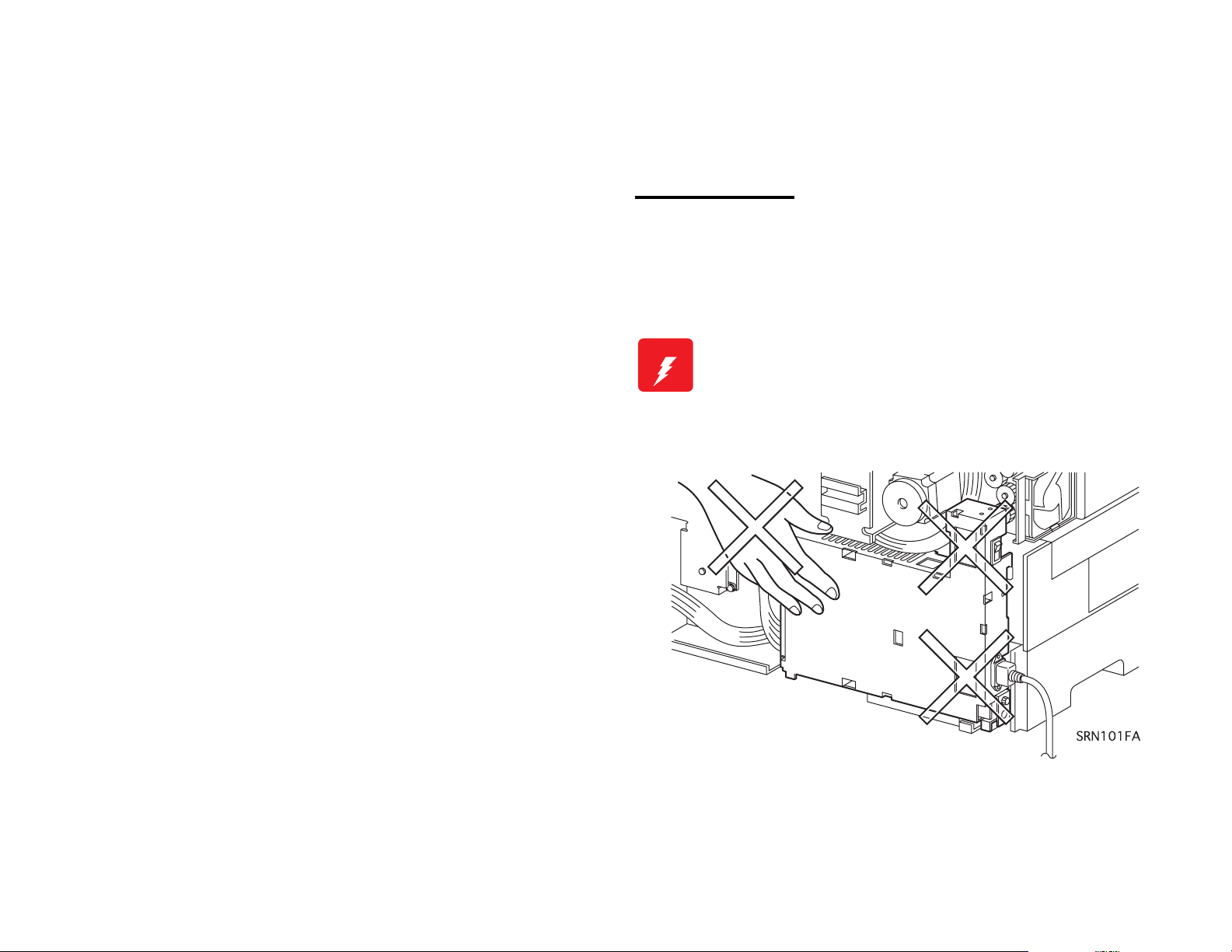
If you service a driving assembly (e.g., gears), first turn off the power
and unplu
W ARNING
the power cord. Then manually rotate the assembly.
Do not touch the driving part (e.g., gears) while the
assembly (printer) is being driven.
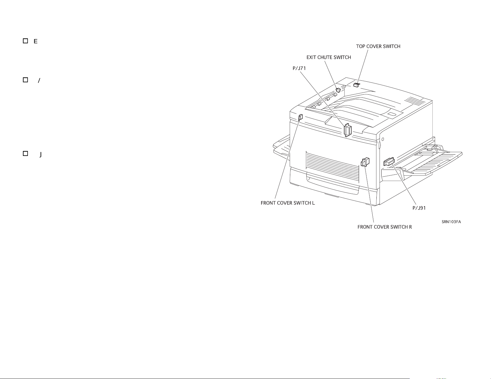
The printer is equipped with safety components (e.g., interlock
switches, fuses, thermostat) and safety switches for protectin
and service personnel from injury and the equipment from dama
The printer has two interlock switches, two saf ety switches and two
interlock connectors that serve as the main safety mechanism.
Front Cover Switch R
This switch is turned off when the Front Cover Assembly is opened.
It cuts off the power supply (24VDC, 5VDC-LD) from the power
supply unit to stop all operat ions and di sconnec ts the out put (5VDCLD) circuit from the power supply and stops the laser beam
emission.
This switch consists of the followin
A switch that cuts off the power supply (24VDC, 5VDC-LD) to
the control circuits and related parts.
A switch that directly cuts off the power supply circuit (5VDC-LD)
to the laser beam output circuit.
Front Cover Switch L
This is a safety switch. This switch is turned off when the Front
Cover Assembly is opened, causin
to stop operatin
.
two switches:
the printer without control units
users
e.
Top Cover Switch
This is an interlock switch that directly cuts off the power supply
(5VDC-LD) circuit to the laser beam output circuit. This switch is
turned off when the Top Cover Assembly is removed, cuttin
output (5VDC-LD) circuit from the power supply unit and stoppin
the laser beam emission.
off the
Page 8
g
g
g
g
g
Exit Chute Switch
This switch is a safety switch. Thi s switch i s turned off when t he Exit
Upper Assembly (the cover on the upper left side of the printer) is
opened.
P/J91 (Connector that connects the Main Harness Assembly and
istration Harness Assembly)
Re
This is an interlock connector that cuts off the power supply
(24VDC, 5VDC-LD) to the control circuit and related parts.
This connector is disconnected when the Main P/H Assembly (pullout type unit on the ri
the output (24VDC, 5VDC-LD) from the power supply and stoppin
the printer operation without control units.
P/J71 (Connector that connects the Fuser Connector and Fuser
Harness Assembly)
This is an interlock connector that cuts off the power supply
(24VDC, 5VDC-LD) to the control circuit and related parts.
This connector is disconnected when the Fuser Assembly (pull-out
type unit on the left side of the printer) is pulled out, cuttin
output (24VDC, 5VDC-LD) from the power supply and stoppin
printer operation without control units.
ht side of the printer) is pulled out, cutting off
off the
the
Page 9
Laser Beam
g
The printer has two interlock switches: the Front Cover Switch R and
the Top Cover Switch. The purpose of these switches is to turn off the
laser beam emission if any of t he pri nter cover s ha ve been op ened; this
protects the user or service personnel from exposure to the laser beam
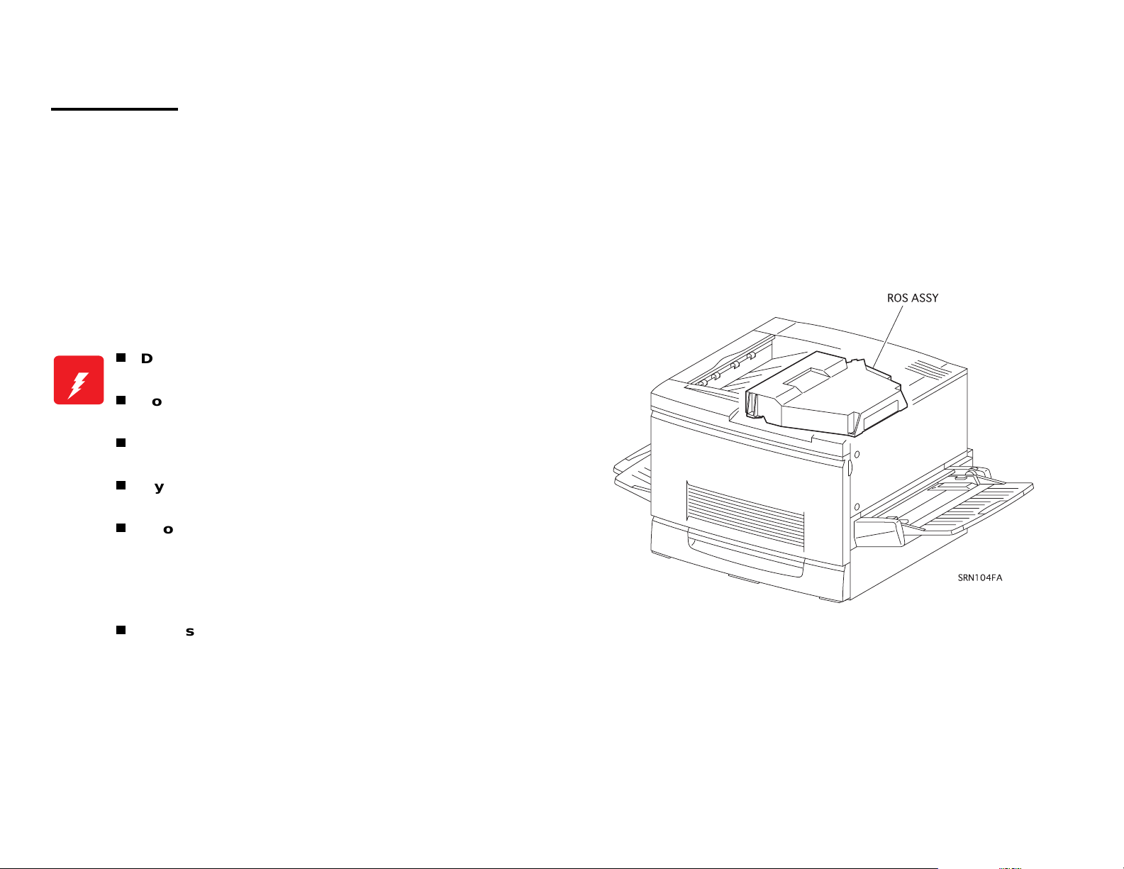
from the ROS Assembly.
NOTE:The laser beam has a narrower frequency band and more
coherent phases than any other light (s unlight , electr ic light ).
It has excellent monochromaticity and convergence. A thin
laser beam reaches long distances. Because of its
convergence characteristic, the laser beam converges into
one point, causing high density and high temperature. A
laser beam is harmful to the human body.
A laser beam may be emitted durin
turn on these interlock switches simultaneously under any
circumstances except in a normal operation.
W ARNING
Do not expose yourself to the laser beam to prevent
injury (blindness).
Do not open the cover that has the laser beam
warning label.
If you disassemble or assemble the printer, turn off
the power.
If you need to work on the printer with power applied,
strictly follow the instructions in thi s manual.
If you have to activate the printer while pressing the
Front Cover Switch R by hand or with a tool, remove
the Top Cover. (Do not turn on these interlock
switches simultaneously under any circumstances
except in a normal operation.)
Understand how the laser beam functions and take
maximum precautions not to injure yourself or anyone
around you.
a maintenance operation. Do not
NOTE:The laser beam in this printer is invisible.
Page 10
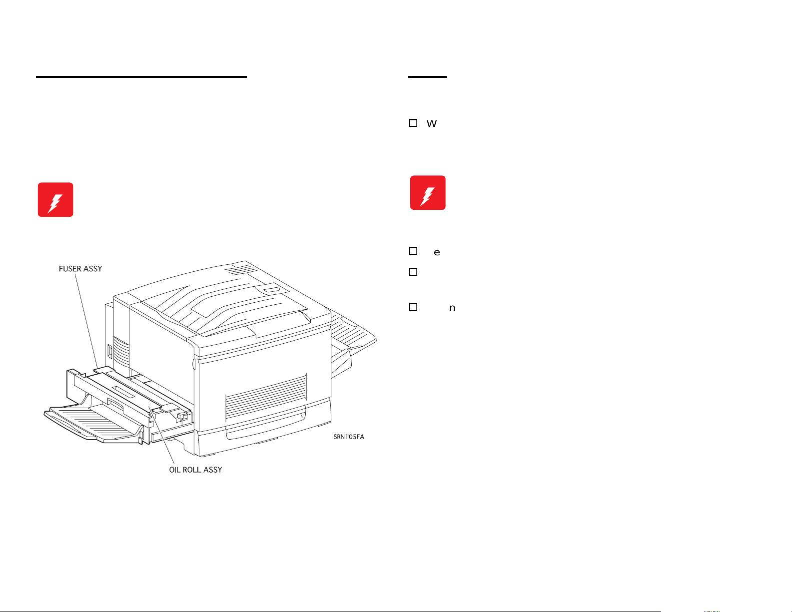
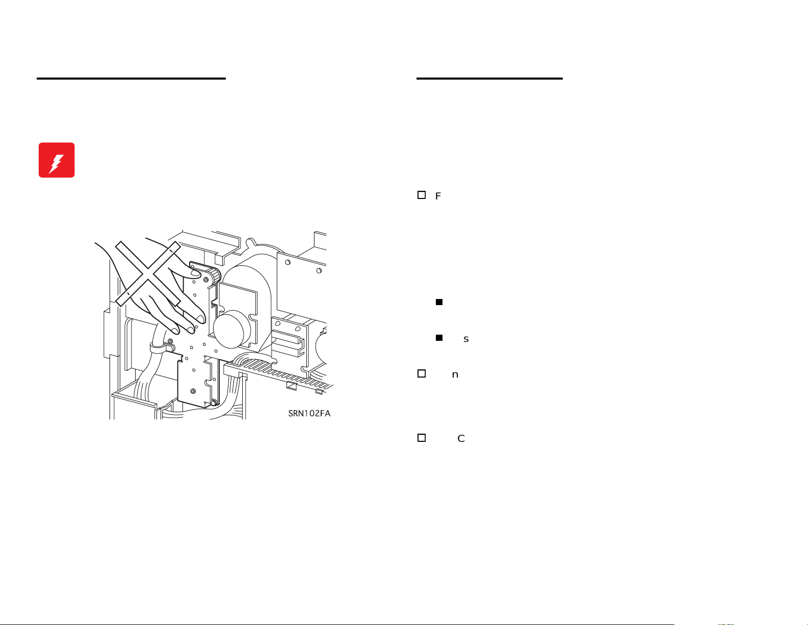
High Temperature Assembly
g
g
g
g
g
Parts
To prevent you from becoming injured or burned, do the following:
Before workin
Assembly), turn off the power, unplu
cools down.
W ARNING
with a high temperature Assembly (e.g., Fuser
the power cord and wait until it
The high temperature Assembly is very hot
immediately after any printer operations. Wait at least
40 minutes before you start working on the printer.
To prevent you from becoming injured, keep the following in mind:
When handlin
posture to protect your back whenever you lift, move or place parts.
W ARNING
Be careful not to injure yourself with the sharp ed
Do not work with wet or oily hands-you may drop a part or injure
yourself. Dry your hands first.
When pullin
force. Pull out the part carefully and slowly step by step.
Do not lift, move or place heavy parts in a body posture
that is likely to cause injury to yourself or cause the
part to drop.
heavy parts (including the printer itself), use good
es of the parts.
out a part (including a harness), do not use too much
Page 11

Consumables
g
g
g
g
Improper Printer Use
Some parts may cause a particulate explosion or fire if handled
improperly. Do not handle these parts near fire or throw into a fire.
Some materials (e.
Do not swallow or inhale these materials or allow them to come in
contact with the eyes.
Help to protect those around you and follow the prohibiti ons a
swallowin
all times.
Place a sheet inside or under the printer so that the floor or workbench
is protected.
If the Developer or Fuser Oi l
wash with clean water.
NOTE:The printer has the following consumable parts:
or inhaling those materials. Be caref ul to protect the eyes at
•
Drum Cartridge
•
Oil Roll Assembly
•
Toner Cartridge M
•
Toner Cartridge Bk
., Developer or Fuser Oil) may cause bodily injury.
ainst
ets on your clothing, dry it with a c loth and
•
Waste Toner Box
•
Toner Cartridge Y
•
Toner Cartridge C
Modifying, revising, tampering with the printer, especially to the safety
mechanism, is strictly prohibited in all circumstances.
Page 12
Page 13

Manual Contents
y
Chapter 1 Product Descriptions
Chapter 2 Operating Principles
Chapter 3 Disassembly and Assembly / Adjustment
Chapter 4 Diagnostics
Chapter 5 Troubleshooting
Chapter 6 Maintenance
Appendix
Revision Status
Revision Issued Date Description
(Preliminar
revision)
Page 14

PRODUCT DESCRIPTIONS
Page 15

Tabl e of Co nt en t s
Features.................................................................................................. 1
Specifications........................................................................................ 3
Basic Specifications.......................................................................... 3
Paper Specification......................................................................... .. 8
Reliability and Durability.................................................................. 11
Operating Environment................................................................... 13
Environmental Conditions for Storage and Transportation............. 14
Electrical Specification.................................................................... 14
Process Specifications .................................................................... 15
Applicable Standards ...................................................................... 16
Options and Consumable Products ................................................ 16
Toner cartridge 17
Drum Cartridge 18
Fuser Oil Roll 18
Waste Toner Box 19
Regularly Replaced Parts ............................................................... 19
Exterior Dimensions........................................................................ 19
Controller Specifications................................................................. 20
Controller Board Jumper Settings................................................... 21
Interface Specifications . ..................................................................... 21
Parallel Interface Specification........................................................ 22
Ethernet Interface........................................................................... 24
Type B Interface.............................................................................. 25
Control Panel....................................................................................... 26
Appearance and Descriptions......................................................... 26
LED Description 27
Button Functions............................................................................. 28
Service Functions................................................................................ 30
Hex Dump Mode............................................................................. 30
Support Mode ................................................................................. 30
EEPROM Initialization..................................................................... 30
Formatting the Flash ROM Module................................................. 31
Updating the Program ROM ........................................................... 31
ROM Module Copy ......................................................................... 31
Panel Setting Initialization............................................................... 31
Maintenance Mode......................................................................... 31
Error Recovery Operation............................................................... 32
Panel Setting........................................................................................ 33
Setting Methods.............................................................................. 33
OneTouch mode 33
Sele cType mode 33
SelecType Setting Menu List. ......................................................... 35
Details of Menus and Settings........................................................ 39
RAM Expansion.............................................................................. 45
Page 16

EPSON ColorPage EPL-C8200 Revision A
1.1 Features
64-bit high speed memory: SDRAM DIMM
(Same as EPL-C8000)
The EPSON ColorPage EPL-C8200 is a non-impact color page printer
that is designed based on the EPL-C8000. This printer is mainly
improved on a controller basis. The main features of the pri n ter are as
follows:
Engine features (Same as for EPL-C8000)
1. Designed for performance in true business environments. Supports
sizes from A5 to A3W. Printing speed (on A4/Letter) is 4ppm for
color printing, 16ppm for monochrome printing.
2. Supports high-resolution full color (True 600dpi).
3. Can generate high-quality prints on special (dedicated) paper.
4. Supports thick sheets and OHP (dedicated OHP sheets).
5. Easy to maintain for a color laser printer.
6. The printer is equipped with the 2 standard paper feed bins; Paper
tray (150 sheets; A3W) and standard universal cassett e (250
sheets: A3).
7. Installing an optional 500-Sheet Paper Cassette Unit provides 4
bins with a maximum capacity of 900 sheets.
With a Large Capacity Paper Unit installed, the printer has 5 bins
holding up to 1150 sheets.
64MB RAM standard: expandable up to 256MB (2 expansion
slots) (Same as EPL-C8000)
2. Color management technology
Enhanced ASIC supported
Color management technology included in hardware for faster
image manipulation
AcuLaser Color Halftoning and CRIT (Color RIT) supported
New compression technology enables further reduction in RAM
use compared to EPL-C8000.
3. Monochrome print technology
AcuLaser Color Halftoning (for Color Copy Stati on 8200) and
RIT supported
4. Two standard interfaces
Bi-directional parallel I/F: IEEE1284 compliance, ECP
Ethernet interface (100Base -TX/10Base-T)
5. installation of expansion RAM (DIMMs) improves the fol lowing:
AcuLaser Color Halftoning drawing area
Print data processing speed
Resolution
6. Toner save mode for both black and monochrome prints enabled.
8. Standard paper ejection is face down (up to 250 sheets). Face-up
ejection is also available (up to 150 sheets).
Controller features (Specific to EPL-C8200)
1. Newly developed high-speed controller
New 64-bit RISC CPU: R5000- 200MHz
7. ROM update function with a flash DIMM installed (for RCC)
8. HDD (Hard Disk Drive) can be installed.
Chapter 1 Product Descriptions 1-1
Page 17
EPSON ColorPage EPL-C8200 Revision A
Software features
1. ESC/Page-Color increases AcuLaser Color Halftoning speed.
2. Bidirectional EJL and MIB can retri eve printer status and mo nitor the
printer environment.
3. Remote panel function using the Web browser (for JAVA JSSK1.1)
4. Electrical sort system with an optional HDD
Expanded I/F data buffer size (for Ethernet I/ F only)
Font registration in the PostScript3 mode
5. Full compatibility with the EPL-N2700:
LJ4, GL2, 1239X, ESC/Page (monochrome)
6. Supports PostScript3 when used with an optional EPSON RIP
Station XXXX or Adobe PostScrip 3 Module.
7. Used with SC6000 (optional), color copy (EPSON Color Copy
Station) is enabled.
8. Font Management function by the EPSON FONT Manager
Supports 96 screen fonts, including 31 fonts suppor ted by the
printer.
Figure 1-1. Exterior View of the EPL-C8200
Chapter 1 Product Descriptions 1-2
Page 18
EPSON ColorPage EPL-C8200 Revision A
1.2 Specifications
This section describes specifications for this printer.
1.2.1 Basic Specifications
Method: Semi-conductive laser beam scanning and
dry electrophotographic process
Resolution: 600 DPI
Print mode:
B/W mode: St andard monochrome print mode that
supports the fastest speed.
Color mode: Color mode which uses the color toner of Y,
M, C, and BK.
Speed mode:
Standard mode: Transports paper at the highest speed
supported by the printer.
Half speed mode: Low speed mode that enables better fusing
for thick paper (over 105 g/m
OHP sheet.
Print speed: See Table 1-1.
2
) envelopes, and
Table 1-1. Speed Mode
Print mode Speed mode LT/A4 LEF*1 2UP
B/W Standard mode 16 PPM or more 8PPM or more
Half speed mode 2.7 PPM or more 1.3PPM or more
Color Standard mode 4 PPM or more 2PPM or more
half speed mode 1.8 PPM or more 0.9PPM or more
*1: [LEF, or Long Edge Feed]
The longer edge of the paper is the top toward the paper feed direction.
[SEF, or Short Edge Feed]
The shorter edge of the paper is the top toward the paper feed direction.
*2: In this mode, the printer prints two print images on the IBT bel t and the images
are transferred in seque nc e on to two sh eets of paper. It is available for L T/A4
(LEF) or smaller.
First print*:
Face-up: B/W: 20 seconds or less (LT/A4 LEF)
*2
B(LD)/A3 SEF
Color: 42.6 seconds or less (LT/A4 LEF)
Face-down: B/W: 24.9 seconds or less (LT/A4 LEF)
Color: 47.6 seconds or less (LT/A4 LEF)
NOTE: First print is def ined as the du ration taken a fter receiv ing the
start command until outputting the first pri n t. It is applicable
when a feeder is selected in the standard mode. (Not
applied during the process control opera ti on.)
Warm-up time: Within 300 seconds
(at 22
°C, 55% Rh, rated voltage)
*1
Chapter 1 Product Descriptions 1-3
Page 19
EPSON ColorPage EPL-C8200 Revision A
Paper handling: See Table 1-2.
Table 1-2. Paper Feeding
Paper source Available feeder
Standard Tray (MSI)
Cassette
Unit*
Standard universal
2 *7
cassette
*1 *6
Standard feeder 250 sheets
Optional A3W cassette Standard feeder 250 sheets
Optional Large
Capacity Paper Unit *
Optional 500-Sheet
Paper Cassette Unit *
250 x 3 feeder
3
(option)
250 x 2 feeder
4
(option)
*1: Change the side guide position in the MSI tray for paper whose width is more than 304.8mm (12”)
*2: Each casssettes is equi pped with the side guide a nd end guide that als o serve to detect paper siz e. They are set by the use r. With an optional
Large Capacity Paper Unit installed, 4 cassettes (maximum) can be used and, including a standard tray, up to 1150 sheets can be set.
*3: Composed of 3 p ap er c as set ts (eac h h ol ds 250 sheets). Each pa per cassette unit is c om pa tib le with a standard uni ve rsa l c as sette and can
be set in any slot.
*4: Composed of 2 p ap er c as set ts (eac h h ol ds 250 sheets). Each pa per cassette unit is c om pa tib le with a standard uni ve rsa l c as sette and can
be inserted in any slot.
*5: Note the following points when setting envelopes:
- Open flaps and set them facing to the tailing side.
- Set envelopes with the longer edges first. Length (excluding flap) must be shorter than width.
- The minimum length with a flap open must be 143mm.
- The minimum width must be 90mm.
*6: Paper out condition is detected.
*7: Paper out and paper near empty conditions are detected for each cassette.
Paper near empty condition: 40 sheets ± 30 sheets (condition: Fuji Xerox L paper, 64g/m
Capacity
(Thickness)
150 sheets
90 x 139.7 - 330.2 x 457.2 mm 60 - 105g/m2, 16 - 20 lb (N ormal
Paper size Available paper thickness
(16mm)
75 sheets 90 x 139.7 - 330.2 x 457.2 mm
OHP sheet/Labels/Thick paper
20 sheets Envelopes
*5
Monarch, C10, DL, C6
B5 LEF, Letter LEF, A4 LEF,
(28mm)
B4, A3, Legal, Executive LEF,
Ledger (B)
A3W (304.8 x 420 - 328 x 453
(28mm)
250 sheets
(28mm)
mm)
Letter LEF, A4LEF, B4, A3,
Legal LEF, Executive LEF,
Ledger (B)
2
)
paper, Recommended paper)
105 - 220g/m
2
(Thick paper, Special paper)
2
60 - 105g/m
(Normal paper,
Recommended paper)
60 - 105g/m2 (Normal paper,
Recommended paper)
60 - 105g/m2 (Normal paper,
Recommended paper)
Paper size: See Table 1-3 .
Chapter 1 Product Descriptions 1-4
Page 20
EPSON ColorPage EPL-C8200 Revision A
Table 1-3. Paper Size / 2-UP Mode Availability
Paper setting orientation
Paper Size
Standard tray
(MSI)
Standard cassette A3W cassette
Normal paper
A3W 328 x 453mm SEF SEF Unavailable
A3 297 x 420mm SEF SEF Unavailable
A4 210 x 297mm LEF LEF Available
A5 148 x 210mm LEF Available
B4 257 x 364mm SEF SEF Unavailable
B5 182 x 257mm LEF Available
I-B5 176 x 250 LEF Available
LT
HLT
LG
EXE
GLG
GLT
B (LD)
F4 210 x 330 SEF Unavailable
8.5 x 11”
(215.9 x 27 9.4mm)
5.5 x 8.5”
(139.7X215.9mm)
8.5 x l4”
(215.9X355.6mm)
7.25 x 10.5”
(184.15X266.7mm)
8.5 x 13”
(215.9X330.2mm)
8 x 10.5”
(203.2 x 26 6.7mm)
11 x 17”
(279.4 x 43 1.8mm)
LEF LEF Available
LEF Available
SEF SEF Unavailable
LEF LEF Available
SEF Unavailable
LEF Available
SEF SEF Unavailable
Special paper
OHP Sheet
MON
C10
DL 110 x 220mm LEF* Available
C6 114 x 162 LEF* Available
8.5 x 11”
(210 x 297mm)
3 7/8” x 71/2”
(98.43 x 19 0.5mm)
41/8 x 91/2
(104.78 x 241.3mm)
LEF Available
LEF* Available
LEF* Available
2UP mode
availability
Notes
• LEF: Long edge is loaded first.
• SEF: Short edge is loaded first.
• 2UP is available only for paper size of LT(LEF) or
smaller. For custom size paper, paper length along
the loading direction must be 8.5 inch or shorter. As
for envelopes, the total length including the opened
flap part must be 8.5 inch or shorter.
• The minimum size of paper set in the standard
universal paper cassette is EXE (LEF).
• The maximum size of paper set in the MSI tray is
330.2 x 457.2 mm (13” x 18”).
• When setting envelopes (LEF*), open their flaps and
set the rear ends of the flaps toward paper feeding
direction.
• A3W cassette have capability for only A3W paper.
Chapter 1 Product Descriptions 1-5
Page 21
EPSON ColorPage EPL-C8200 Revision A
Paper aligning: Single side aligning (front side) for all sizes
(both standard tray (MSI) and each cassette)
Consumables:
TONER CARTRIDGE (Black, Cyan, Magenta, Yellow)
DRUM CARTRIDGE (including one WASTE TONER BOX)
WASTE TONER BOX
OIL ROLL
Regularly replaced parts:
MAIN FUSER ASSEMBLY
Air filter (replaced with the MAIN FUSER ASSEMBLY
BELT CLEANER ASSEMBLY
2ND BTR ASSEMBLY
Normal paper A3W Available HLT Unavailable
Special paper OHP sheet FU* C10 FU*
Table 1-4. Face-Down Output Availability
Paper Size FD Availability Paper Size FD Availability
A3 Available LG Available
A4 Available EXE Available
A5 Unavailable GLG Available
B4 Available GLT Available
B5 Available B(LD) Available
LT Available F4 Available
I-B5 Unavailable
Postcard FU* DL FU*
MON FU* C6 FU*
Paper output:
Face-down (FD):
250 sheets (B5/EXE or larger, up to 105g/m
Face-up (FU):
150 sheets (smaller than A4)
50 sheets (A4 or larger)
See Table 1-4 FD availability for each paper size.
2
or 28lb
NOTE
1. The minimum paper size available for FD ejection is 182 mm in the paper feeding
direction x 210 mm vertical to the paper feeding direction.
2. “FU*” in the FD availability columns means face-up ejection for OHP, thick paper,
and envelope.
Dimensions (without option):
728 (W)* mm x 641 (D)* mm x 490 (H) mm (tolerances:
± 1%)
* When the standard tray (MSI) and Output tray (FU) are stored.)
Weight: 68.4 kg ± 1% (without option)
Voltage: 110V/120V
220V/240V
Power consumption, Rated current:See Table 1-5.
± 10%, 50/60Hz ± 3Hz
± 10%, 50/60Hz ± 3Hz
Chapter 1 Product Descriptions 1-6
Page 22
EPSON ColorPage EPL-C8200 Revision A
Table 1-5. Power Consumption Specifications
Operating (color)
Operating (B/W)
Power
consumption
Rated current
*1:
Saves more energy than in standby mode. Time required for warning up
Standby mode
Energy save mode 1
Energy save mode 2*2
• 100 V: 11A or less (at rated voltage)
• 115V: 10A or less (at rated voltage)
• 240V: 5A or less (at rated voltage)
is shorter.
*2:
Completely non-operating condition. Complies with the Energy Star.
• Average: 400Wh or less
• Maximum: 1100W or less (Fuser: On)
• Average: 500Wh or less
• Maximum: 1100W or less (Fuser: On)
• Average: 250Wh or less
• Maximum: 1000W or less (Fuser: On)
100W or less (Fuser: Off)
• Average: 200Wh or less
*1
• Maximum: 1000W or less (Fuser: On)
100W or less (Fuser: Off)
• Average: 45Wh or less
• Maximum: 1000W or less (Fuser: On)
100W or less (Fuser: Off)
Product life
Printer: Approximately 180,000 printed pages on A4 LEF
(450,000 images) or five years, whichever comes first.
Standard tray (MSI): 72,000 sheets
250 sheets x 3 feeders: 135,000 sheets (45,000 sheets x 3)
Acoustic noise: Operating = 54.8dB (A) or less
Stand-by = 38.3dB (A) or less
Energy Save mode 1 = 38.3dB (A) or less
Energy Save mode 2 = 35.0dB (A) or less
Ozone emission: 0.02 ppm (time waited average value) or less.
Toxicity: Photo conductor, toner, carrier , plastic
material have no effect on human body.
Chapter 1 Product Descriptions 1-7
Page 23

EPSON ColorPage EPL-C8200 Revision A
1.2.2 Paper Specification
Paper specifications: See Table 1-6.
Table 1-6. Paper Specifications
Paper Type
Recommended paper 4024 paper (B/W), X-pression paper (color)
Normal Paper Normal copier paper, Recycled paper,
Special Paper OHP film, Card stock, Labels, Color paper, Thick
NOTE: lb: Ream Weight = lb/500sheets/17” x 22”
2
g/m
= 0.2659763 lb
1
NOTE: Before purchasing a large amount of paper, try it ou t and
check that it is properly fed.
NOTE: Avoid using the types of paper listed below to prevent
abnormal printing, paper jam, and printer malfunction.
- C arbon paper, non-carbon paper, thermal paper, impact paper,
acidic paper
- Paper that has gone through a thermal or an ink-jet printer.
- Paper that is too thick or thin.
- Wet (damp) paper
- Paper to which a special coating has been applied, or colored
paper that has gone through surface process.
- Paper that has been lubricated (too smooth or slippery).
- Paper whose texture is different on the front and back.
- Paper with holes for binders and perforations.
- Paper with irregular shape or not cut with right angles.
- Paper with labels that come off and stick easily.
- Paper with glue, staples, or paper clips attached.
- Special ink-jet paper (Super Fine Paper, glossy film, and so on.)
- OHP sheets for other color laser printers, monochr ome printers,
and photocopiers.
2
- 105g/m2 (16lb - 28lb)
60g/m
paper (105g/m
2
- 220g/m2), DTP paper, Envelopes
- Paper that has gone through other color laser printers,
monochrome printers, and photocopiers.
- Pasted paper
Chapter 1 Product Descriptions 1-8
Page 24
EPSON ColorPage EPL-C8200 Revision A
Paper source classification:See Table 1-7.
Table 1-7. Paper Usability for Each Paper Source
Paper source
Standard (MSI) tray RF P P P P P P
Standard universal cassette RF P N N N N N
A3W cassette*
Large Capacity Paper Unit
500-Sheet Paper Cassette Unit
3
*3
Recommended
paper
RF P NNNNN
RF P N N N N N
Normal
paper
OHP
sheet
Postcard Labels
Special paper
Thick
paper*
1
Envelope
2
*
NOTE: RF
*1:
105 - 220g/m
*2:
MON, C10, DL, C6
*3:
Option
Guaranteed print area: See Figure 1-2.
: Reliable feeding and good image quality, P: Possible, but limited to paper generally available, N: Not supported
2
4m m 4m m
4m m
G uaranteed
print area
4m m
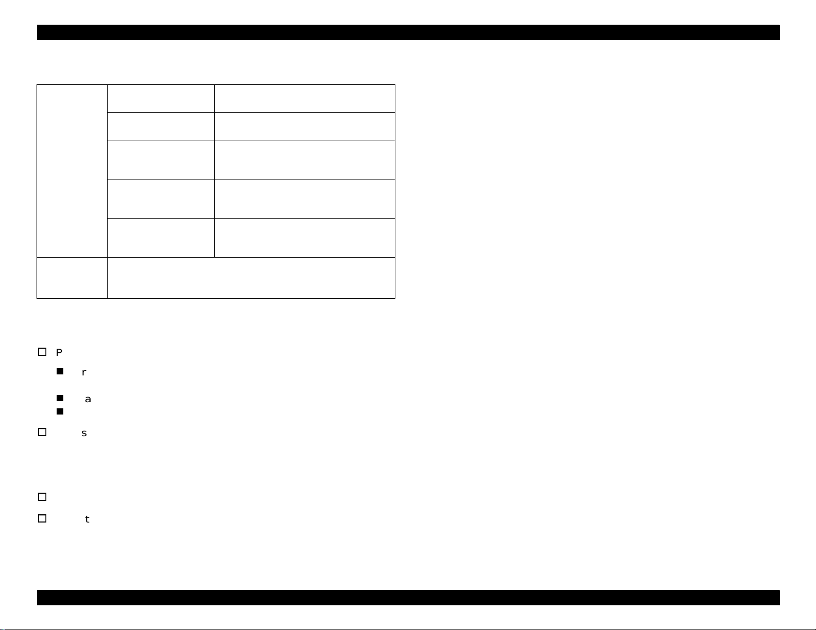
Maximum guaranteed print area:
Area with a margin of 4 mm from each side
Applied to a paper size up to 297mm (11.7”) width x 431.8mm (17”)
length.
Maximum printable area:
320mm (12.6”) width x 449.2mm (17.7”) length
Figure 1-2. Guaranteed Print Area
Chapter 1 Product Descriptions 1-9
Page 25
EPSON ColorPage EPL-C8200 Revision A
r
Printable area:
Paper whose width is 304.8mm (12”) or shorter: From the edge
When the standard universal cassette, Large Capacity Pape r
Unit, or 500-Sheet Paper Cassette Unit is used.
Paper whose width is longer than 304.8mm (12”)*: From the point
with a margin of 5mm
* When loading paper whose width is more than 304.8 mm (12”),
4m m
4m m
304.8m m (12,6")
296.8m m (11.7")
4m m
the standard cassette (MSI) is shi fted and pri nt positi on starts with
a margin of 5 mm from the paper edge (a). This change is applied
to paper loaded from the A3W cassette.
When the standard tray (MSI) or A3W cassette is used.
330.2m m (13")
4m m
457.2m m (18")
(a )
320m m (12,6")
297m m (11.7")
Printable
area
Paper feeding direction
457.2m m (18")
431.8m m (17")
Printable area
Paper feeding direction
Side guide position for paper w hose w idth is 304.8 m m (12") or less
M axim um size of paper: 304.8 m m (11.2") w idth x 457.2 m m (18") length
Printable area: 296.8 m m (11.7") w idth x 449.2 m m (17.7") length
G uaranteed print area: 296.8 m m (11.7") w idth x 431.8 m m (17") length
Figure 1-4. Printable Area 2
Side guide position for paper w hose w idth is 304.8 m m or shorte
Side guide position for paper w hose w idth is m ore than 304.8 m m
Length betw een the guides is 12.6m m
M axim um size of paper: 330.2 m m (13") w idth x 457.2 m m (18") length
Printable area: 320.0 m m (12.6") w idth x 449.2 m m (17.7") length
G uaranteed print area: 297 m m (11.7") w idth x 431.8 m m (17") length
Figure 1-3. Printable Area 1
Chapter 1 Product Descriptions 1-10
Page 26
EPSON ColorPage EPL-C8200 Revision A
a
b
c
d
e
f
Print area
Paper feeding direction
1.2.3 Reliability and Durability
MPBF:
Printer including standard tray (MSI):
38,000 pages or more (95,000 images or more*)
Printer including optional 250 sheet x 3 feeders:
32,000 pages or more (80,000 images or more*)
Print position accuracy:
Main scan direction:Reference position (c)
Sub scan direction:Reference position (a)
± 2.5 mm
± 2.0 mm
See Figure 1-5.
Paper skew: See Figure 1-5 and Table 1-9.
NOTE: Figured out based on the MPBF in condition that the job
ratio of the color and monochrome prints is 1: 1, since 1
page of color print is formed with 4 images.
Paper feed reliability: See Table 1-8.
Table 1-8. Paper Feed Reliability
Recommended
paper
Standard paper tray
Paper jam rate 1/500 or less 1/100 or less 1/100
Multiple feeding rate 1/ 80 or less 1/50 or less 1/50
Standard universal cassette / Large Capacity Paper Unit / 500-Sheet Paper
Cassette Unit(option)
Paper jam rate 1/3,000 or less 1/2,000 or less
Multiple feeding rate 1/800 or less 1/500 or less
A3W cassette (option)
Paper jam rate 1/2,000 or less
Multiple feeding rate 1/500 or less
* Do not feed envelopes at high temperature to avoid adhering.
* Statistics for envelopes only apply to front fac e feeding u nder norma l temper-
ature. (back side feeding is not in cluded.)
NOTE: Paper jam or multiple feeding occurred to the top sheet of
Normal paper Special paper *
Figure 1-5. Paper Skew
Table 1-9. Paper Skew
Direction A4 (landscape) A3
Main scan direction (|c-d| )
Sub scan direction (|a-b|)±2.0mm(e=271mm)
1.5mm(f=196mm)
±
3.0mm(f=406mm)
±
2.0mm(f=271mm)
±
an added stack of paper is ignored.
Chapter 1 Product Descriptions 1-11
Page 27

EPSON ColorPage EPL-C8200 Revision A
Durability:
Printer:
180,000 sheets* (450,000 images) A4 LEF or 5 years,
whichever comes first. Parts regularly repl aced by the service is
ignored.
* 450,000 sheets if the printer is used for monochrome print only. In
color printing, one page is formed with 4 images, and the value
“180,000” sheets is figured out in the condition that the job ratio of
monochrome and color printings is 1:1.
Standard tray (MSI): 72,000 sheets
250sheets x 3 feeders: 135,000 sheets (45,000 sheets x 3)
MTTR: Within 30 minutes (average)
Curl height at ejection:Less than
± 15mm (Color printing with the
image ratio of 5% in non- aligned condition,
which varies depending on the image rate
and aligning pattern.)
Chapter 1 Product Descriptions 1-12
Page 28
EPSON ColorPage EPL-C8200 Revision A
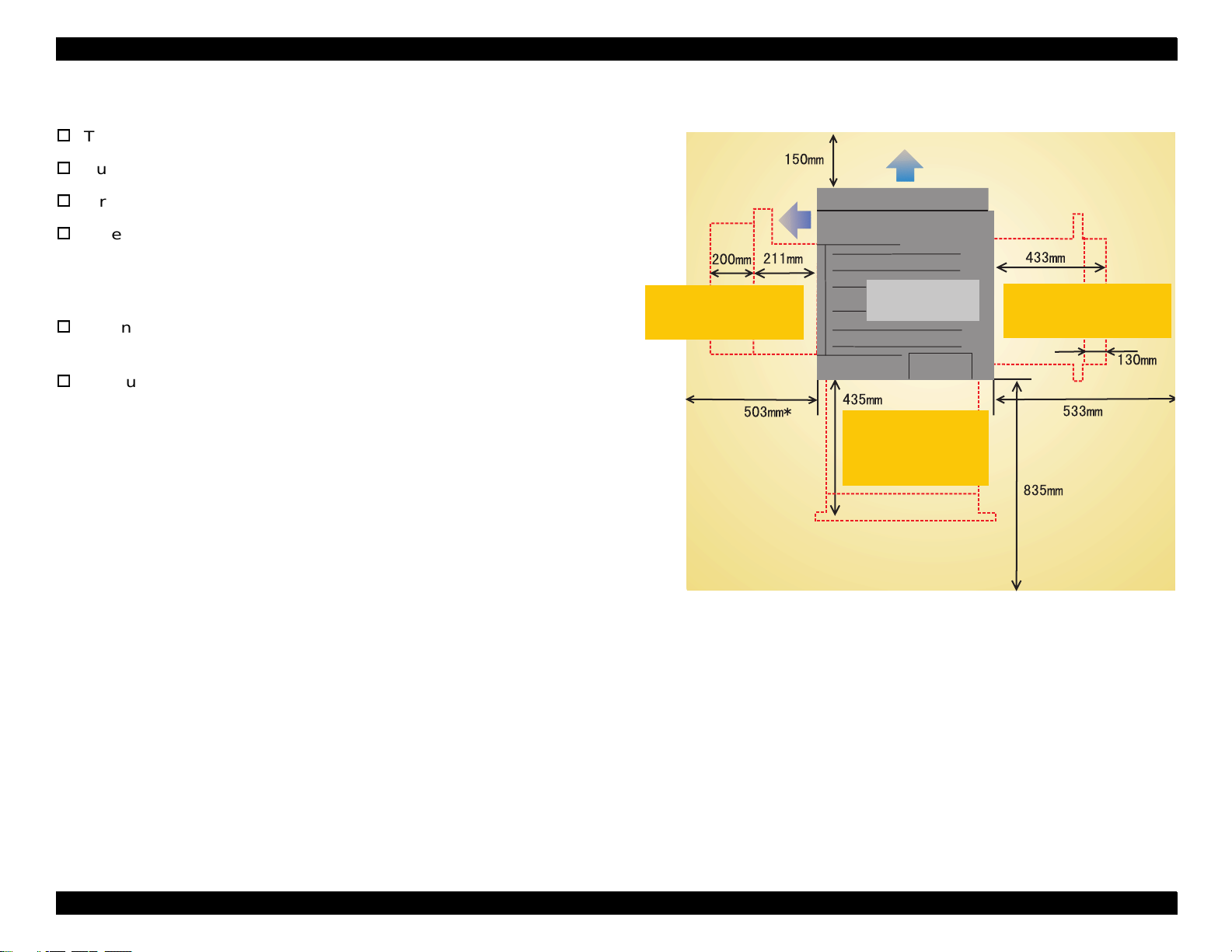
1.2.4 Operating Environment
Temperature: 10 to 32°C
Humidity: 15% to 85% RH (without condensation)
Air pressure (altitude):760 hPa or more (2500 meters or les s)
Levelness:
Front - rear direction on the table:5mm or less (within 641mm)
Right - left direction on the table:10 mm or less (within 560mm)
Luminosity: 3000 lux or less (not to exposed to direct
sunlight)
Surrounding environment:See Figure 1-6.
Ventilation
R equired w hen pullin g
out the FU SE R U N IT
to remove jammed paper.
* 511 m m w ith a face-up tray installed.
Ventilation
R equired w hen pulling out
the paper path unit to
rem ove jam m ed paper.
R equired w hen pullin g
out the standard paper
c a s s e tte u n it to lo a d
paper.
Figure 1-6. Space Requirement
Chapter 1 Product Descriptions 1-13
Page 29
EPSON ColorPage EPL-C8200 Revision A
1.2.5 Environmental Conditions for Storage and Transportation
temperature and Humidity:See Table 1-10.
Table 1-10. Environmental Conditions 1
Temperature Humidity Guaranty
Normal condition 0 - 35
Extreme condition High: 35 - 40 °C
*1:
Without condensation.
Storage air pressure (altitude)
C 15 - 80%RH
°
Low: -20 - 0
C
°
High: 80 - 95%RH*
Low: 5 - 15%RH*
0 - 2500 meters (0 up to 15000m is possible during ai r shippi ng, but
the air pressure in the cargo room must be 0.7 hPA or more.)
Drop test: See Table 1-11.
Table 1-11. Drop Test
Height Test times
Bottom: 457 mm (18”) Once
Free drop
Ridge drop 45 7 mm (18”)
Resistance to vibration
Frequency: 2 - 500 Hz
Acceleration: 12.6 m/s
Direction: 3 directions (X, Y, Z)
Duration: 30 minutes (single way)
Other than bottom: 305mm (12”)
2
(on a vibrating board)
*1: Overall rms value
*2: Z=vertical, X and Y=horizontal
*1
Once for each surface
(total of 5 times)
Once for each side
(total of 4 times)
*
2
For 12 months
One month (Max.)
*
1
1.2.6 Electrical Specifications
AC line noise
Pulse width: 50 to 1000 ns
Pulse polarity:
Repeat: Not synchronized
Modes: Common/normal
Voltage: 1kv (However, the parts can withstand up to
Instant cutoff: DIP 100% (at rated voltage-10%) for one
Electrostatic durability:
No possibility of any error which affects on print quality under the
following conditions.
Atmospheric discharging:
Contact discharging:
Rush current: 1/2 cycle, 100A or less
Insulation resistance: 10 M Ω or more
Dielectric strength:
There is no breakdown when the following voltages are applied for
one minute.
100V/120V model:
AC 2000V (Between primary and secondary sides)
AC 1000V (Between primary side and chassis)
220V/240V model:
AC 2000V (Between primary and secondary sides)
AC 1500V (Between primary side and chassis)
+/−
2kv without damage.)
cycle with normal print quality.
± 8KV
± 6KV
Chapter 1 Product Descriptions 1-14
Page 30
EPSON ColorPage EPL-C8200 Revision A
Leakage current:
100 V model: 0.5mA or less
120V model: 3.5mA or less
220V/240V model: 3.5mmA or less
Condition: 1.5K Ω, 0.15uF
(between non-metallic parts and frames)
1.2.7 Process Specifications
Printing method: Dry electrophotographic with 2 ingredients
Using the intermediate belt transfer system
Light source: Semi-conductive laser beam
Exposed object: OPC drum (organic photo conductor)
Charging method: Roller transfer system
Developing method: Exposed part developing system
Toner: Single-ingredient nonmagnetic toner with
carrier
1st transfer: Intermediate belt transfer system
2nd transfer: Roller transfer system
Fusing: Heat roller system
Density adjustment: Automatic (can not be set by user)
Chapter 1 Product Descriptions 1-15
Page 31

EPSON ColorPage EPL-C8200 Revision A
1.2.8 Applicable Standards
Safety standards
100V/120V:
UL1950 2nd Edition, CSA C22.2 No. 950-M89
220V/240V:
IEC950 2nd Edition/1991 by VDE with GS-mark
Safety regulations
100V/120V:
FDA21CFR Chapter 1, Subchapter L, Section 1010, 1040
220V/240V:
IEC825 Class l Laser Product
NOTE: Laser power: 5mW (rated)
+
10/-15nm (at 25 °C)
Wavelength: 785nm
EMI
US: FCCPart15 SubpartB, ClassB(ANSI 63.4/11.4D)
Europe: EN55022(CISPR Pubilication22), ClassB
Followings will become effective in January,
2001:
EN61000-3-2 (Hamonics)
EN61000-3-3 (Flicker)
Others
Toner: No effect on human health (OSHA, TSCA,
EINECS)
Carrier: No effect on human health
1.2.9 Options and Consumable Products
The following table shows the options and consumable products for
EPL-C8200.
Table 1-12. Options and Consumable Products for EPL-C8200
Options Code Consumable Products Code
Large Capacity Paper Unit C81301* Toner Cartridge (Yellow) S050016
500-Sheet Paper Cassette
Unit
250 Sheet Lower Paper
Cassette Unit A3W
Hard Disc Drive C82377* Toner Cartridge (Black) S050019
Adobe PostScript 3 Kit C83236* Waste Toner Collector
EPSON RIP Station XXXX Fuser Oil Roll S052002
32KB Serial Interface Card C82307* Photoconductor unit (DRUM
32KB Parallel Interface Card C82310* EPSON Color Laser Paper
Coax Interface Card C82314* EPSON Color Laser Paper
Twinax Interface Card C82315* EPSON Color Laser Paper
LocalTalk Interface Card C82312* EPSON Color Laser Paper
GPIB Interface Card C82313* EPSON Color Laser
- - EPSON Color Laser
C81335* Toner Cartridge (Magenta) S050017
C81302* Toner Cartridge (Cyan) S050018
S050020
(WASTE TONER BOX)
S051061
CARTRIDGE)
S041215
(A4)
S041216
(A3)
S041217
(A3W)
S041218
(Letter)
S041175
Transparencies (A4)
S041174
Transparencies (Letter)
OPC: No effect on human health (OSHA)
Ozone: UL478 (5th edition)
Material: SWISS environmental law (must contain no Cds)
* Asterisk varies depending on the market.
Chapter 1 Product Descriptions 1-16
Page 32

EPSON ColorPage EPL-C8200 Revision A
1.2.9.1 Toner cartridge
Toner Cartridge life: See Table 1-13.
Storage air pressure:
0 - 2,500m (0 up to 15,000 m is possible during air shi ppin g, but the
air pressure in the cargo room must be 0.7 hPA or more.)
Table 1-13. Toner Cartridge Life
Item Life
Toner Cartridge (Black) 4,500 images
Toner Cartridge (Cyan) 6,000 images*
Toner Cartridge (Magenta) 6,000 images*
Toner Cartridge (Yellow) 6,000 images*
*: Defined under the con diti on s t hat the im ag e ra tio is 5% on A4 (LEF) paper during
continuous printing, and different in color printing. Also, life varies depending on
the image ratio and printer usage, weather continuous or intermittent.
Dimensions and weight:
See Table 1-14. (Tolerances for dimensions and weight are both
±
Drop test:
Height: 91 cm
Resistance to vibration:
Frequency: 5 - 100 Hz
Acceleration: 0.7G
Direction: 3 directions (X, Y, Z) *2
Duration: 50 minutes (single way) for each direction
(1 corner, 3 sides, 6 surfaces)
1%)
Table 1-14. Dimensions and Weight
Unpacked Packed
Dimensions (WxDxH) 50 mm(W) x 400mm (D) x
54.5mm (H)
Weight Black: 0.39kg
Y/M/C: 0.39kg
85 mm(W) x 435mm (D) x
80mm (H)
Black: 0.48kg
Y/M/C: 0.48kg
Environmental conditions for storage and tr ansportation:
Temperature/Humidity: See Table 1-15.
Table 1-15. Temperature/Humidity
Temperature Humidity Guaranty *1
Normal condition 0 - 35
Extreme condition High: 35 - 45 °C
*1: Without condensatio n
*2: 12 months for unpacked cartridges under the used condition.
C 15 - 80% RH *1 24 months
°
High: 80 - 95% Rh*1
Low: -20 - 0
C
°
Low: 5 - 15% Rh*1
1 month (Max.)
Chapter 1 Product Descriptions 1-17
Page 33
EPSON ColorPage EPL-C8200 Revision A
1.2.9.2 Drum Cartridge
Specifications: See Table 1-16.
Table 1-16. Photoconductor Unit Specifications
Specifications
Formation Photoconductor, drum cleaner, waste toner box
Life 20,000 sheets *1 (same for the waste toner box)
Dimension (WxDxH)
2
*
Weight • Unpacked: 2.45 kg
Environmental
condition f or storage
and transportation
*1: Defined under the co ndi tio ns t hat the image ratio is 5% on A4 (LEF ) pap er
during continuous printing, and different in color printing. Also, life varies
depending on the im age ratio and printer usage , w ea ther continuous or intermittent printing.
*2: Tolerances for dimensions and weight are both
• Unpacked: 213 mm(W) x510 mm (D) x 181 mm (H)
• Packed: 318 mm(W) x 618 mm (D) x 280 mm (H)
• Packed: 3.5 kg
Same as for Toner Cartridge
1%
±
1.2.9.3 Fuser Oil Roll
OIL Roll specifications: See Table 1-17.
Table 1-17. Fuser Oil Roll Unit Specifications
Specifications
Formation Oil roll
Life 20,000 sheets *1
Dimensions (WxDxH)
2
*
Weight • Unpacked: 0.68 kg
Environmental
condition for storage
and transportation
*1: Varies depending on the operating conditions, as follows:
- Operating rate is 120 sheets / day or more: 20,000 sheets
- Operating rate is 120 sheets / day or less: 11,000 sheets
*2: Tolerances for dimensions and weight are both
• Unpacked: 75 mm(W) x 421 mm (D) x 48 mm (H)
• Packed: 160 mm(W) x 600 mm (D) x 130 mm (H)
• Packed: 1 kg
Same as for Toner Cartridge
±
1%
Chapter 1 Product Descriptions 1-18
Page 34

EPSON ColorPage EPL-C8200 Revision A
(
)
1.2.9.4 Waste Toner Box
WASTE TONER BOX specifications:See Table 1-18.
Table 1-18. Waste Toner Box
Specifications
Formation Waste toner box and others
Life 20,000 sheets *1
Dimensions (WxDxH)
2
*
Weight • Unpacked: 0.45 kg
Environmental
condition f or storage
and transportation
*1: Defined under the c onditions that the i mage ratio is 5% o n A4 (LEF) printing
at 4P/J. Life varies depen ding on the i mage ratio and p rinter usag e, weather continuous or intermittent printing.
*2: Tolerances for dimensions and weight are both
• Unpacked: 80 mm(W) x 444 mm (D) x 131 mm (H)
• Packed: 149 mm(W) x 495 mm (D) x 192 mm (H)
• Packed: 0.87 kg
Same as for Toner Cartridge
1%
±
1.2.10 Regularly Replaced Parts
The regularly replaced parts (replaced by servi ce engineers) and their
lives are as follows.
1.2.11 Exterior Dimensions
Exterior dimensions of the EPL-C8200 are as follows.
641m m (D )
560m m (W )
H
490m m
728m m (W )
1367.4m m (M ax.)
MAIN FUSER ASSEMBLY 100,000 sheets
Figure 1-7. Exterior Dimensions of EPL-C8200
(including the ventilation filter)
2ND BTR ASSEMBLY: 100,000 sheets
Chapter 1 Product Descriptions 1-19
Page 35

EPSON ColorPage EPL-C8200 Revision A
1.2.12 Controller Specifications
CPU: R5000 (200MHz)
Enhancement technologies:
AcuLaser Color Halftoning (monochrome print)
RIT, CRIT
RAM: SDRAM 64-bit-wide DIMM (168-pin, 3.3V)
Maximum: 256MB
3 RAM slots, including 1 used for the standard
RAM
Standard: 64MB
Expansion: 32MB, 64MB, 128MB, 256MB
ROM: 32-bit-wide
Program: 4MB (ROM DIMM)
Font: 4MB
Expansion ROM: 3 slots (ROM DIMM slots)
Printer modes:
Standard: ESC/Page-Color, ESC/Page (B/W), LJ4 (B/W), GL2
(B/W), ESCP2 (B/W), FX (B/W), 1239X (B/W)
Optional: Postscript3 (PostScr ipt3 module, Peacock-B)
Others: EJL, PJL, RCC
Supplementary software:
Status sheet
Network Status Sheet
Opt I/F Status Sheet (with a Type-B level 3 I/F installed)
Font Sample (each mode)
Hex dump
Support Mode
Maintenance mode (Engine Status Sheet)
Slot A, B: Font ROM module, PostScript3 module, CM table
Slot C: NLSP font ROM module only
Panel: 1-line 20-Character LCD, 6 LEDs, 8 switches
Interfaces:
Standard: Parallel, 1ch
1EEE-1284-compliant bidirectional
B-type connector
Compatibility
Nibble
ECP
Ethernet
100Base/TX, 10Base/T, 1ch
Optional: Type-B - 1 slots (for l evel 3)
Printer settings: Made through the panel setting mode, EJL
commands, and MIB
Chapter 1 Product Descriptions 1-20
Page 36

EPSON ColorPage EPL-C8200 Revision A
1.2.13 Controller Board Jumper Settings
The controller board confi guration of th is printer ca n be set for the t arget
market (destination) as indicated bel ow. The settings are made at
factory (by jumper resistor).
Factory paper default switch setting betwee n A4 and Letter:
[Letter] North/South American
[A4] European
Pacific/Russian
Taiwanese
Chinese
Korean
Paper size switch setting for the cassette:
[EXE] North/South America
European
Pacific/Russia
[B5] Taiwanese
Chinese
Korean
1.3 Interface Specifications
The EPL-C8200 supports the following external interfaces.
Standard: 1. Parallel interface
2. Ethernet interface
Optional: Type-B host interfaces (1 slot)
The host interface usage configurations are as follows.
Table 1-19. Host Interface Usage Configurations
Parallel I/F Ethernet I/F
1. Automatic I/F switching Usable Usable Usable
2. Fixed I/F (Parallel) Usable Not Usable Not Usable
3. Fixed I/F (Etherent) Not Usable Usable Not Usable
4. Fixed I/F (AUX) Not Usable Not Usable Usable
Figure below shows the locations of these interfaces.
Type B (AUX)
I/F
Short/Open condition for RJ3 and RJ4:
[RJ3] Open
T y p e -B (A U X ) In te rfa c e
Parallele Interface
(IE E E1284 B -type)
[RJ4] Short
Link/R eception Lam p (G reen)
100Base/10B ase Lam p (O range)
E th e r n e t In te rfa c e
(100BaseTX /10BaseT)
Figure 1-8. Locations of the Interface Slots
Chapter 1 Product Descriptions 1-21
Page 37
EPSON ColorPage EPL-C8200 Revision A
g
1.3.1 Parallel Interface Specification
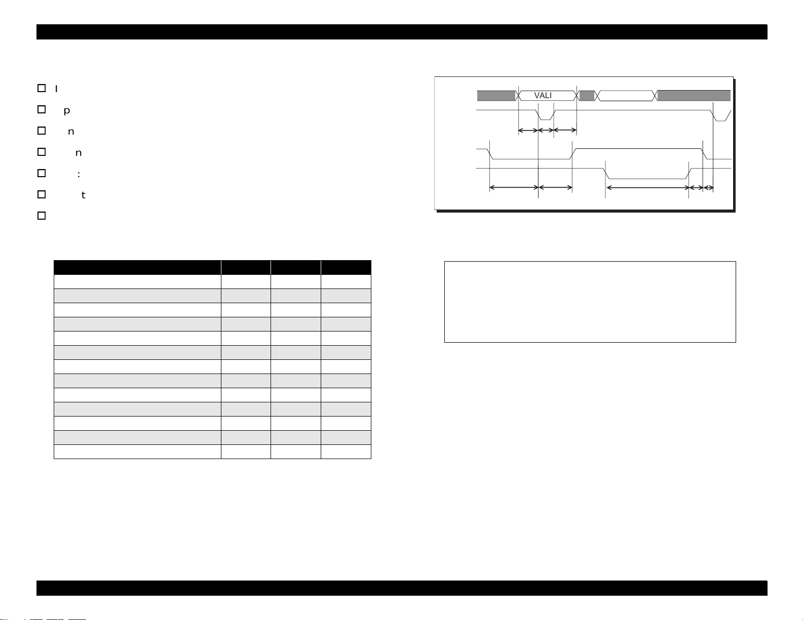
Interface type: IEEE 1284 High-Speed Bi-directional Parallel I/F
Operating modes: Compatibility, Nibble, ECP
Synchronization: /STROBE pulse
Connector type: 57RE-40360-830B(D7A)DDK or equivalent
DATA
STRBX
BUSY
(1 )
VALID
1
VALID
(2 ) (3 )
3
VALID
VALID
2
Plug: Amphenol equivalent
Data transmission timing:Refer to Table 1-20 and Figure 1-9.
Device ID: See Table 1-21.
Table 1-20. Data Transmission Timing
Min. Typ. Max
(1) Data hold setup 0.5 us
(2) Data hold 0.5 us
(3) Strobe pulse 0.5 us
(4) BUSY to STRBX 0 us
(5) STROB to BUSY 0.5 us
(6) BUSY to STRBX 0 us
(7) ACKX pulse width 0.5 us 1 us*
(8) ACKX to BUSY 0 s
(9) BUSY to PE or ERRX 2 ms*
(10) PE or ERRX to BUSY 2 ms*
(11) Power on to signal output valid 05 s
(12) PE or ERRX to ACKX 2 ms*
(13) STRBX to ACKX 0 s*
ACKX
(4 ) (5 ) (6 )(7 ) (8 )
7
8
6
8
6
Figure 1-9. Data Transmission Timing
Table 1-21. Device ID
*1;
MFG:
CMD:
MDL:
CLS:
DES:
EPSON;
PJL, EJL, ESCPL2, ESCP9, PRPXL24-01, PCL, HPGL201, ESCPAGE-04, ESCPAGECOLOR-01*2;
*3;
PRINTER;
*4;
*1: Total length of Device ID + 2 (hex)
*2:
POSTSCRIP
*3: Model name
*4: Manufacture and product name
is added when a PostScript module is installed.
EPL-C8200
EPSON ColorPa
e EPL-C8200
Note the MFG, MDL, DES, and CID can be defined by the users. The
CID field, which does not reply at initialized device ID, only repl ies with a
user-defined character s trin g. The devic e I D at r e-defi nit ion i s as sho wn
below. A “*****” represents a user-defined character string.
MFG: *****;
CMD: Same as above
MDL: *****;
CLS: PRINTER
DES: *****;
CID: *****;
Chapter 1 Product Descriptions 1-22
Page 38

EPSON ColorPage EPL-C8200 Revision A
Table 1-22. Centronics Parallel Interface Pin Assignment
Pin # Signal Names I/O Descriptions
1 STRBX I Latch pulse used to read data. DATA is valid when the signal is LOW.
2-9 DATA 1-8 I DATA 8 is MSB and DATA 1 is LSB.
10 ACKNLGX O An acknowledge pulse to the host that indicates the data from the host
computer has been received.
11 BUSY O HIGH status indicates the printer is not ready to accept data.
12 PE O Indicates paper empty status in paper tray or cassette selected.
13 SELOT O Always HIGH.
14 AUTOX I When the signal is LOW, the printer automatically feeds a line as “CR” is
input. The “CR” is detected when the printer is turned on or the interface
selection is switched from the optional I/F to parallel I/F.
15 NC - Not used.
16 GND - Ground level for the twisted pair return.
17 CG - Connected to the printer chassis. The printer chassis GND and the signal
GND are connected each other.
18 NC - Not used.
19-30 GND - Ground level for the twisted pair return.
31 INITX I When the signal is LOW, the STRBX signal is ignored.
32 ERRX O The signal is LOW when the printer is in the following condition:
User maintenance is required.
Service maintenance is required.
Another type of error has occurred.
The printer is off line.
33 GND - Ground level for the twisted pair return.
34 NC - Not used.
35 +5V - Pu lled up to +5V through 1K Ω resistor.
36 SELINX I Always LOW.
Chapter 1 Product Descriptions 1-23
Page 39

EPSON ColorPage EPL-C8200 Revision A
1.3.2 Ethernet Interface
Interface type*: 10BaseT
100BaseTX
Half Duplex
Full Duplex
*: Switched at power on
Communication protocol:
1. IPX/SPX (IPX, SPX, NCP, RIP, SAP, PrintServer,
RemotePrinter, NDS, SNMP, ENPC)
2. NetBIOS (SMB)
NetBEUI
3. TCP/IP (IP, UDP, TCP, LPR, FTP, TELNET, APR, ICMP,
RARP, BOOTP, DHCP, SNMP, HTTP, ENPC)
4. AppleTalk (ELAP, DDP, ATP, PAP, AARP, NBP, ZIP, RTMP,
SNMP, ENPC)
Connector type: RJ45
Table 1-23. Pin Configuration for the Ethernet I/F
Pin Signal Name I/O
1Tx+ O
2Tx- O
3Rx+ I
4N.C. 5N.C. 6 Rx- I
7N.C. 8N.C. -
Applicable cable: 2-pair STP (10BaseT, 100BaseTX)
NOTE: Use a shielded cable to meet FCC Class B, EN55022 Class
B, and VCCI Class B.
Pin configuration: See Table 1-23.
Entity type: See Section 3.3.3 Type B Interface.
Chapter 1 Product Descriptions 1-24
Page 40
EPSON ColorPage EPL-C8200 Revision A
1.3.3 Type B Interface
This printer is equipped with a slot for Type B option al interface.
Main system type: MTP600dpi, PW774dt600doi, PRG(
rev. AP2000ma, SPD0fast, D4
*: “
∗ ∗ ∗ ∗ ∗
Printer name: Same as the Product name at factory.
Product name: EPL-C8200
Emulation type / Entity type: See Table 1-24.
“Represents ROM version.
∗ ∗ ∗ ∗ ∗)*
Entity type
1. Emulation = Auto:See Table 1-24.
2. Emulation Menu = Fixed
The entity type of the default emulation,
EPSONCOLORPAGE is returned.
Table 1-24. Type B I/F Emulation/Entity Type
Emulation Emulation Type Entity Type
*1
PS
ESC/Page Color ESCPAGECOLOR-01 EPSONPAGECOLOR1
ESC/Page ESCPAGE-04
LJ4 PCL5E-00 EPSONPCL5
*2
RCC
1239X PRPXL24-01 EPSONPRPXL24
GL2 HPGL24-01 EPSONHPGL2
FX ESCP9-84 EPSONFX
ESCP2 ESCPL2-00 EPSONLQ2
POSTSCRIPT-00
--
*1
LaserWriter
*1
*1: Added with PostScript3 module attached.
*2: Can not be selected by users.
Emulation type
1. Emulation = Auto
When PS is active: AUTO (Emulation Type 1,2,3,...)
When PS is inactive: EJL(POSTSCRIPT-00, other
Emulation Type 1,2,3...)
2. Emulation Menu = fixed
EJL (Default Emulation Type, Other Emulation Type 1,2,3,
...)
Chapter 1 Product Descriptions 1-25
Page 41

EPSON ColorPage EPL-C8200 Revision A
1.4 Control Panel
This section describes the control panel of this printer and its functions.
1.4.1 Appearance and Descriptions
The control panel of this printer consists of the LCD, 8 buttons, and 6
LEDs. See Figure 1-10 and Tabl e 1-25 for th e control panel appearance
and its descriptions, respectively.
J
DE
Paper Source P aper S ize M anual Feed O rientation
SelecType
K
Alt
FG
RITech
Menu Item Value
L
C opies M P Tray Size
MN
Toner Save
Mode
Enter
O
On Line
H
A
B
Form Feed
I
C
C ontinue
Reset
Figure 1-10. Control Panel Appearance
Table 1-25. LEDs and Switches on the Control Panel
LED Button
Location Name Remarks Location Name Remarks
A LCD Panel
B On Line LED Green I Form Feed button
C Data LED Yellow J Continue button
D Continue LED Red K SelecType/Alt button Also serves as the Shift button
E OneTouch Mode 1 LED L Menu Select button
F OneTouch Mode 2 LED M Item Select button
G SelecType Mode LED N Value Select button
- - O Enter button
1 line, 20 characters
(5 x 7 dot matrix)
H On Line button
Chapter 1 Product Descriptions 1-26
Page 42

EPSON ColorPage EPL-C8200 Revision A
1.4.1.1 LED Description
LCD (Liquid Crystal Display) (A)
One-line display for 20 characters (5 x 7 dot matrix)
Normally displays printer status.
In panel setting mode, LCD displays various setting val ues.
On Line LED (B)
On: The printer is on-line.
Off: The printer is a pause status.
Form Feed LED (C)
On: Unprinted data remains in the printer. However, the
lamp is not lit if the remaining data is not effective
print data but other data such as control codes
including commands.
Off: No effective print dat a remains in the printer. If
control codes are not terminated, the indicator is lit.
Blinking: The printer is processing data.
Continue LED (D)
OneTouch Mode 2 LED (F)
On: OneTouch mode 2 is enabled. The following 4 items
can be set in this mode:
- RITech
- Copies
- Mp Tray Size
- Toner Save Mode
SelecType Mode (G)
On: SelecType mode is enabled.
All LEDs
All LEDs come on when a service-call error has occurred.
Blinking: An error has occurred which can be cleared by
pressing the Continue button.
OneTouch Setting Mode 1 LED (E)
On: OneTouch mode 1 is enabled. The following 4 items
can be set in this mode:
- Paper Source
- Paper Size
- Manual Feed
- Orientation
Chapter 1 Product Descriptions 1-27
Page 43

EPSON ColorPage EPL-C8200 Revision A
1.4.2 Button Functions
On Line button (H)
When the printer is on-line, pressing this button puts the printer in
off-line to prevent printing. Pressed during panel setting mode, it
immediately terminates the setti ng mode and brings the prin ter back
to on-line status.
Form Feed button (I)
If the Form Feed lamp is lit in off-line status, pressi ng this button
causes the printer to print a page of data. If data for multipl e pages
has been received, it is printed. If t he Form Feed LED is lit because
the control codes are not terminated, the data recei ved up to that
point is printed. The printer does not eject paper when the Form
Feed LED is on.
Continue button (J)
While the Continue LED is on, pressing this button clears the error.
Also, a warning message indicated during on-line status can be
cleared by pressing this button.
Menu button (L)
Pressing this button activates the SelecType mode, and the
initial level of the mode (“Test Menu”) appears. In the SelecType
mode, this button is used to select the setting menu, t he primary
level of the mode.
In OneTouch mode 1, used to select the value for “Paper
Source”.
In OneTouch mode 2, used to select the item for “RITech”.
In SelecType mode, used to select the setting menu.
NOTE: If this button is pressed with the Shift button held down,
setting values and items scroll backward.
Item button (M)
Pressing this button brings up the item that was last selected.
In OneTouch mode 1, this button is used to select the value for
“Paper Size”.
In OneTouch mode 2, this button is used to select the value for
“Copies”.
In SelecType mode, this but ton is us ed to se lec t the set ting i tem.
NOTE: If this button is pressed with the Shift button held down,
setting values and items scroll backward.
SelecType button (K) (or Shift button)
Used to select OneTouch mode 1 / OneTouch mode 2 / SelecType
mode, as follows:
The first push of the button puts the printer in OneTouch mode
1.
Pressing this button in the OneTouch mode 1 puts the printer in
OneTouch mode 2.
Pressing this button in the OneTouch mode 2 activates the
SelecType mode to enter the initial level of SelecType mode.
(The “Test Menu” appears.)
Value button (N)
Pressing this button enables the item that was last selected.
In OneTouch mode 1, used to select the value for “Manual
Feed”.
In OneTouch mode 2, used to select the value for “MP Tray
Size”.
In SelecType mode, used to select the value for the currently
selected setting item. The next available value for the item is
indicated.
NOTE: If this button is pressed with the Shift button held down,
setting values and items scroll backward.
Chapter 1 Product Descriptions 1-28
Page 44

EPSON ColorPage EPL-C8200 Revision A
Enter button (O)
Pressing this button generates “Status Sheet” in “Test Menu”.
In OneTouch mode 1, used to select the value for “Orientation”.
In OneTouch mode 2, used to select the value for “Toner Save
Mode”.
In SelecType mode, the setting value is confirmed and printing
or other functions are activated.
NOTE: If this button is pressed with the Shift button held down,
setting values and items scroll backward.
Reset button (Continue button + Alt button) (K + J)
Pressing this button with the Alt butt on held down caus es the printer
to stop printing and reset. Af ter th e message “ Reset ” is indi cat ed on
the LCD, if the both buttons are kept pressed for more 5 seconds,
“Reset All” is indicated and warm boot is performed.
Chapter 1 Product Descriptions 1-29
Page 45

EPSON ColorPage EPL-C8200 Revision A
1.5 Service Functions
Turning the printer on while pressing the specified button(s) until RAM
check is completed provides several service functions. The service
functions supported with this print er are as listed below.
Hex Dump Mode
Support Mode
EEPROM Initialization
Panel Setting Initialization
Formatting the Flash ROM Module
Updating the Program ROM
ROM Module Copy
Maintenance Mode
CPU Reset During Service-Call Error
Error Sheet Print
NOTE:Following modes are not supported.
Total page counter clear
Total Counter Clear in the Maintenance Menu is substituted.
Toner level reset
Remaining toner level is evaluated based on the dispense time
on the engine side.
1.5.1 Hex Dump Mode
Buttons: Form Feed + Power on
Functions: “Hex Dump” is indicated. Received data is converted
into hex ASCII. This is vali d for a ll i nte rfaces. The he x
damp sheet contains the following information:
-Dump list with the received data in hex ASCII format
-Data list with 1-byte code characters (Unreadable
characters are expressed by *.*.)
-Page number
-Termination:Press “Reset” button to perform warm
boot or turn the printer off and back on.
1.5.2 Support Mode
Buttons: Value + Power on
Functions: Adds the support mode to t he setting menu list. Once
it is added, the printer performs warm-boot, then the
support mode can be selected and executed. The
support mode enables servicers to set items,
including HDD initialization, that are normally not set
by users.
1.5.3 EEPROM Initialization
Buttons: On Line + Continue + Menu + Power on
Functions: Clears the EEPROM to 00h and writes factor y default
values. All values except for the values below are
cleared; IBT Cleaner, 2ND BTR, Fuser Unit, and
accumulated printed pages counter value. (Ref er to
Section 1.5.8.)
Termination: After initializing, the printer performs warm boot and
returns to the normal states.
Chapter 1 Product Descriptions 1-30
Page 46

EPSON ColorPage EPL-C8200 Revision A
1.5.4 Formatting the Flash ROM Module
Buttons: Alt + Item + Value + Enter + Power on
Termination: After initializing, the printer performs warm boot and
returns to the normal states.
Functions: Clears the flash ROM module inserted in the slot A. It
starts as the message “DIMM A ERASING” appears.
Termination: After formatting the flash ROM module, the printer
performs warm boot and return s to the normal st ates .
1.5.5 Updating the Program ROM
Buttons: On Line + Alt + Value + Power on
Functions: Updates the DIMM inserted in the program socket.
1.5.6 ROM Module Copy
Buttons: On Line + Alt + Enter + Power on
Functions: Copies the contents of the ROM module in the socket
B to the flash ROM module in the socket A. If ther e is
no module in the socket B, the contents of the ROM
module in the code ROM socket is copied. As the
indication “DIMM COPY MODE” appears, press the
Enter button. The contents of the ROM is erased a nd
copy process is carried out.
Termination: After copying, the printer performs warm boot and
returns to the normal states.
1.5.8 Maintenance Mode
Buttons: On Line + Form Feed + Continue + Power on
Functions: Adds the Maintenance menu to the setting menu.
After this operation, the printer automatically
performs warm boot and the Maintenance menu is
enabled. To eliminate this menu from the setting
menus, turn the printer off and back on. Note that all
engine-related Service-Call Errors (Service-Call
Error e f f f f) are ignored (No Service-Call Error
occurs.) while the Maintenance menu is generated.
(Same as for EJL) Note the following points in the
Maintenance mode:
Interfaces are always open. (Disconnected)
Before entering the Maintenance mode to print an
engine status sheet, make sure no engi ne-rel ated
error is indicated in a normal mode (other than
Maintenance mode).
In this mode, the printer only prints engine status
sheet. In case other printouts such as normal
status sheet is needed, be sure to check that no
engine related error is i ndicate d i n a normal mode
(other than Maintenance mode), as described
above.
1.5.7 Panel Setting Initialization
Buttons: Continue + Power on
Functions: All panel settings for total environment and interface-
specific environment are reset t o the factory def aults.
Information such as accumulated printed pages to
which users have no access is not initialized.
Termination: Turn the printer off and back on.
Chapter 1 Product Descriptions 1-31
Page 47

EPSON ColorPage EPL-C8200 Revision A
1.5.9 Error Recovery Operation
By pressing the specified buttons, the foll owing functions are activated.
a) CPU reset when E***** or C2000 Service call error is indicated
Buttons: Alt + Menu + Item + value + Enter
Functions: Returns the printer to the normal states without
turning off and back on the printer.
NOTE:If the message “Printing SysErr?>” appears after this
operation, an error sheet can be printed by pressing the
Enter button. If any other button is pressed, the printer
returns to the normal status without outputting an error
sheet.
b) Display of error details when E***** or C2000 Service-call error
is indicated
Step 1
Step 2
Step 3
: Press the Continue, Alt, and Menu buttons.
“ERR Y x x x x 0x********” (code and address)
appears. - *1
: Press any button.
“ERR TYPE 0x********” (error type) appears.
: Press any button. The display returns to *1.
NOTE: See Chapter 5 / Section 5.1.3 for Service-call Error code
list.
Chapter 1 Product Descriptions 1-32
Page 48

EPSON ColorPage EPL-C8200 Revision A
1.6 Panel Setting
This printer is equipped with the 2 types of panel setting functions; the
OneTouch mode and SelecType mode. The OneTouch mode allow the
users to get directl y to the spec ific set ting it ems in the Sele cType mode.
Therefore, this manual only lists the setting items for the SelecType
mode.
OneTouch mode 1, 2
There are two OneTouch modes, OneTouch mode 1 and 2. This
mode enables users to make selection by pressing a button in the
panel design matrix.
SelecType mode
The SelecType mode has two levels.
1. Setting menu
Panel setting items fall into numbers of categories cal led se tting
menus.
2. Setting item
This is the lowest level of the panel setting mode. Some items
have values to be s elected and others are just executed directly.
1.6.1 Setting Methods
1.6.1.1 OneTouch mode
NOTE:OneTouch mode is effective when the printer is free from any
error condition.
1. Enter the OneTouch mode 1 or 2 by pressing the
(The current values for 4 items are shown on the LCD.)
2. Scroll the setting value list by pressing the
3. When the desired value is indicated, exit the OneTouch mode, and
the new value is stored.
4. To return to the On Line status from the OneTouch mode, perform
one of the followings:
1) Press the
2) Perform panel setting initialization.
3) Run a status sheet.
4) Press the
On Line
SelecType
button.
button.
SelecType
OneTouch
*: “Menu”, “Item”, “Value” and “Enter” buttons serve as the OneTouch
buttons in this mode.
button.
button*.
1.6.1.2 SelecType mode
NOTE:SelecType mode is effective when no error has occurred.
1. To enter the SelecType mode, perform one of the following
operations:
1) Press the
through the One touch mode 1 and 2.
2) Press the
SelecType
Menu
NOTE: SelecType mode is effective when the printer is free from
any error condition.
Chapter 1 Product Descriptions 1-33
button to enter the SelecType mode
button,
Item, Value
, or
Enter
button.
Page 49
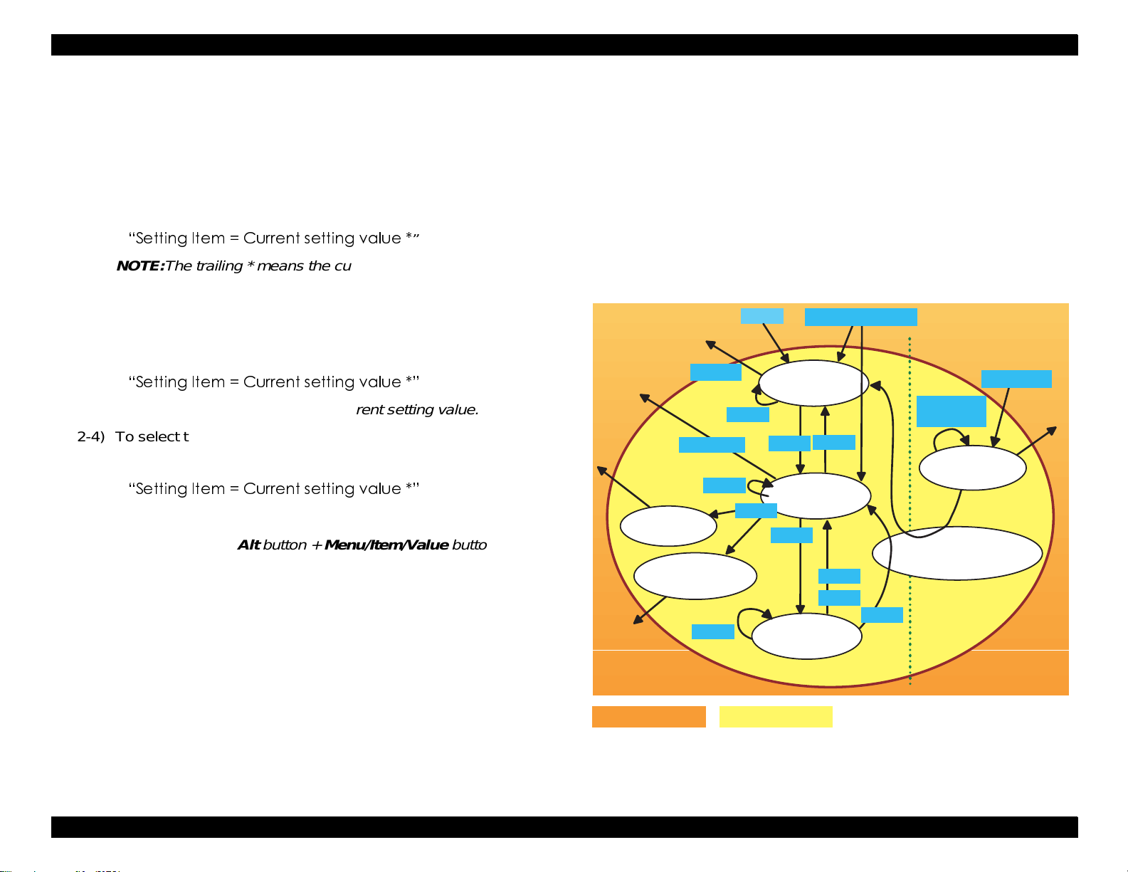
EPSON ColorPage EPL-C8200 Revision A
2. Follow the next steps to operate the SelecType mode.
2-1) In the setting menu select mode, select the desired menu by
pressing the
button. The menus are shown left-aligned
Menu
on the LCD.
2-2) To enter the setting item select mode, press the
Item
button.
The initial item appears in the format below:
”
NOTE:The trailing * means the current setting value.
2-3) In the setting item select mode, press the
button to bring
Item
up the desired item. With each push of the Item button, the
item is switches to the next item, again shown in the format
below:
NOTE:The trailing * means the current setting value.
2-4) To select the value for the selected item, press the
Value
button. Each value available appears in the format below:
NOTE:The trailing * means the current setting value.
NOTE:Using the Alt button + Menu/Item/Value button, it is
possible to cycle through the lists backward.
NOTE:Keeping the Value button (+ Alt button) depressed for
a certain length of time causes the values to change
continuously.
2-5) In the value select mode, press the Enter button when the
desired value is displayed. The value is stored as the
new setting or executed directly. (For the value
previously set, pressing the Enter but ton has no effec t.)
2-6) In the item select mode, pressing the Menu button brings bac k
the setting menu select mode and the next menu is displayed.
2-7) In the value select mode, pressing the Menu or Item button,
the item select mode is brought back.
3. To return to the On Line status from the SelecType mode, perfor m
one of the following operations:
1) Press the
On Line
button.
2) Perform panel setting initialization.
3) Run a status sheet.
4) Press the
In itia liz e
panel settings.
Execute test
print/cleaning print
O n Line status
O n-Line status
SelecType
On Line
M enu
S elecT ype
Ite m
Value
Panel setting m ode
M enu
Enter
button.
Ite m /V a lu e /E n te r
Setting m enu
select m ode
M enu
Ite m
Setting item
select m ode
Value
M enu
Ite m
S e ttin g v a lu e
select m ode
SelecType M ode
S elecT ype
O ne-toucn
setting
O neTouch
m ode
Store in EEPR O M
or perform processing.
O neTouch m ode
Enter
Figure 1-11. Panel Setting Mode Diagram
Chapter 1 Product Descriptions 1-34
Page 50

EPSON ColorPage EPL-C8200 Revision A
1.6.2 SelecType Setting Menu List
This section contains the tables which li st the SelecType sett ing menus.
The factory defaults values are shown in Bold Italic style. The menus
selected through the One-touch mode are shaded.
Table 1-26. Panel Setting Menu List (1/8)
Menu Item Value
Test Menu Status sheet
Network Status Sheet
AUX Status Sheet
PS3 Status Sheet
PS3 Font Sample
ESC/Page Font Sample
LJ4 Font Sample
ESCP2 Font Sample
FX Font Sample
1239X Font sample
Emulation
Parallel
Menu
Network
*6
AUX
Printing Menu
Paper Source
Page Size
Wide A4
Orientation
Out Bin
Copies
Quantity
*11
Manual Feed
Resolution
Skip Blank Page
Auto Eject Page
*12
*2*3
*4
*4
*1
*5
, LJ4, ESCP2, FX, 1239X, PS3*4
Auto
GL2
, LJ4, ESCP2, FX, 1239X, PS3*4
Auto
GL2
, LJ4, ESCP2, FX, 1239X, PS3*4
Auto
GL2
, MP, LC1, LC2*7, LC3*7 LC4
Auto
*9
, A3, A5, B4, B5,
A4
LT
*10
*8
, B, HLT,
LGL, GLT, GLG, EXE, F4, MON,
C10, DL, C6, IB5, CTM, A3W
, On
Off
Land
Port,
Face-down
999
∼
1
999
∼
1
, On
Off
, 300
600
, On
Off
, On
Off
, Face-Up
Menu Item Value
Tray Menu MP Mode
Config Menu RITech
Setup Menu
(Continues to the
next table)
Table 1-27. Panel Setting Menu List (2/8)
Normal
MP Tray Size
A4
GLT, GLG, EXE, F4, MON, C10, DL, C6,
IB5, A3W
LC1 Size
*13
With a stan dard 250-sheet cassette
mounted:
A4, A3, B4, B5
With a 250-sheet lower paper cassette
unit A3 W mounted: A3W
LC2 Size
LC3 Size
LC4 Size
MP Type
*7*13
*7*13
*8*13
A4, A3, B4, B5
A4, A3, B4, B5
A4, A3, B4, B5
Plain
Color, Transprncy, Labels
LC1 Type
LC2 Type
LC3 Type
LC4 Type
*7
*7
*8
Plain
Plain
Plain
Plain
On,
Toner Save
Off,
Top Offset -5.0
Left Offset -5.0
Size Ignore
Auto Cont
Page Protect
Image Optimum
Paper Type
Interface
Off,
Off,
Auto
Auto
Normal,
Auto,
Time Out 0, 5
Standby
*16
Enable
, Last
*9
,
A3, A5, B4, B5,
LT
*14
, LT, LGL, B, EXE
*14
, LT, LGL, B, EXE
*14
, LT, LGL, B, EXE
*14
, LT, LGL, B, EXE
, Letterhead, Bond, Recycled,
, Letterhead, Bond, Recycled, Color
, Letterhead, Bond, Recycled, Color
, Letterhead, Bond, Recycled, Color
, Letterhead, Bond, Recycled, Color
Off
On
∼ 6.0 mm step 0.5 mm
∼
0.0
∼ 6.0 mm step 0.5 mm
∼
0.0
On
On
, On
, Off, On
Thick, Trmsprnc,
Parallel, Network, AUX
∼ 300 step1
∼
60
, Disable
*10
, B, HLT, LGL,
*6
*15
*15
*15
*15
Chapter 1 Product Descriptions 1-35
Page 51

EPSON ColorPage EPL-C8200 Revision A
Table 1-28. Panel Setting Menu List (3/8)
Menu Item Value
Setup Menu
(Continued)
Parallel Menu Speed
Network Menu
(Continues to the
next table)
Lang
Lang
Sprache
LINGUA
LENG
SPRΑK
Sprog
Taal
LANG
Ling
Panel Lock
C Toner
M Toner
Y Toner
K Toner
Total Pages
Color Pages
B/W Pages
*17
*13
*13
*13
*13
*13
*13
*13
SelcType lnit
Bi-D
Buffer Size
Network Confiig
Get IPAddress
IP Byte 1
IP Byte 2
IP Byte 3
IP Byte 4
SM Byte 1
SM Byte 2
SM Byte 3
SM Byte 4
GW Byte 1
GW Byte 2
*19
*19
*19
*19
*19
*19
*19
*19
*19
*19
*19
*18
English
Francais
Deutsch
ITALIANO
ESPANOL
SVENSKA
Dansk
Nederl.
SUOMI
Portugues
On
Off,
E * * * * F, E * * * F, E * * F,
E * F, E F
0 ∼ 99999999
0 ∼ 99999999
0 ∼ 99999999
, Normal
Fast
ECP, Off
Nibble,
Normal,
No
Panel
0 0 0 0 0 0 0 -
0
0 0 -
Maximum, Minimum
, Yes
, Auto, PING
- 255
192
- 255
168
- 255
192
- 255
168
255
255
255
- 255
255
255
Table 1-29. Panel Setting Menu List (4/8)
Menu Item Value
Network Menu
(Continued)
AUX Menu
*6
ESC/Page
*5
Menu
GW Byte 3
GW Byte 4
Buffer Size
AUX Confiig
Get IPAddress
IP Byte 1
IP Byte 2
IP Byte 3
IP Byte 4
SM Byte 1
SM Byte 2
SM Byte 3
SM Byte 4
GW Byte 1
GW Byte 2
GW Byte 3
GW Byte 4
Netware
AppleTalk
NetBEUI
AUX Init
Buffer Size Normal, Maximum, Minimum
Auto CR
Auto FF
CR Function
LF Function
FF Function
Error Code
Avoid Error
PGI
TriColorSpace
CM Media Type
*19
*19
*2*19*20
*2*19*20
*2*19*20
*2*19*20
*2*19*20
*2*19*20
*2*19*20
*2*19*20
*2*19*20
*2*19*20
*2*19*20
*2*19*20
*2*19*20
*2*19*20
*2*19*20
*2*19
*2*18
*2*19*20
0 -
255
0 -
255
Normal
No
, Maximum, Minimum
, Yes
Panel, Auto, PING
0 - 255
0 - 255
0 - 255
0 - 255
0 - 255
0 - 255
0 - 255
0 - 255
0 - 255
0 - 255
0 - 255
0 - 255
ON, Off
On, Off
On, Off
, Off
On
, Off
On
, CR+LF
CR
, LF
CR+LF
, FF
CR+FF
, Space
Ignore
, On
Off
, Off
On
Normal
Off
, sRGB
, Opt1, Opt2
Chapter 1 Product Descriptions 1-36
Page 52
EPSON ColorPage EPL-C8200 Revision A
Table 1-30. Panel Setting Menu List (5/8)
Menu Item Value
LJ4 Menu FontSource
Font Number
*22
Pitch
*22
Height
SymSet
Form 5
Source SymSet 0
Dest SymSet 0
CR Function
LF Function LF,
GL2 Menu
GLMode
Scale
Origin
Pen
End
(Continues to
the next table)
Join
Residen
0
0.44 ∼
4.00
IBM-US
ISO, 8859-15ISO, IBM-DN, PcMultiling,
PcE.Europe, PcTk437, PcEur858, WiAnsi,
WiE.Europe, WiTurkish, DeskTop, PsText,
Velnternati,VeUS, MsPublishin, Math-8, PsMath,
VeMath, PiFont, Legal, UK, ANSI ASCII, Swedis2,
Italian, Spanish, German, Norweg1, French2,
Windows, Pclcelandic
PcPortugues
PcCanFrench
ISO
WiLatvian
BpBRASCII
PcGk851
WiGreek
PcLt866
Bulgarian
ISO
PcAr864
CR
LJ4GL2
Off
Corner
Pen0
Pen6
Butt
Mitered
Beveled, None
t
, Download, ROM A
∼ available (Max 65535)
∼ 99.99 cpi step 0.01 cpi
10.00
∼
12.00
999.75 pt step 0.25 pt
∼
, Roman-8, ECM94-1, 8859-2 ISO, 8859-9
*23
, PcEt850
*23
*23
, 8859-4 ISO
*23
*23
, Hebrew8
∗10
∼
∼
60
∼ 3199
∼
277
∼ 3199
∼
277
, PcSl437
*23
, Mazowia
*23
, BpAbicomp
*23
, PcGk869
*23
, Europe3
, 8859-5 ISO
*23
, PcUkr866
*23
*23
, 8859-6 ISO
*9
∼ 128 lines
64
, CR+LF
CR+LF
, Gllike
, A0, A1, A2, A3
, Center
,
Pen1, Pen2
*24
, Square, Triangular, Round
, Miteredbeveled, Triangualr, Round,
*23
, PcLt774
*23
*23
*23
, WiBaltic
*23
, CodeMJK
*23
,8859-7 ISO
*23
, PcCy855
*23
, WiCyrillic
*23
, Hebrew7
, PcHe862
*23
, OCR A
*24
Pen3
*21
, ROM B
*23
, PcTurk2
, PcNordic
*23
, WiEstonian
*23
, PcGK437
*23
*23
, Arabic8
*24
, Pen4
*21
, PcTurk1
*23
,
*23
, 8859-3
*23
,
*23
*23
,
, PcCy866
*23
,
*23
, 8859-8
*23
*23
, OCR B
*24
, Pen5
Table 1-31. Panel Setting Menu List (6/8)
Menu Item Value
GL2 Menu
(Continued)
PS3 Menu
*23
*23
,
,
ESCP2 Menu Font
,
*23
,
,
*23
*24
,
Pen0 0.05
Pen1 0.05 ∼
*24
Pen2
*24
Pen3
*24
Pen4
*24
Pen5
*24
Pen6
*4
Error Sheet
Coloration
Image Protect
Pitch
Condensed
T.Margin 0.40
Text 1
CGTable
Country
Auto CR
Auto LF
Bit Image
ZeroChar
∼ 5.00 mm step 0.05 mm
∼
0.35
∼ 5.00 mm step 0.05 mm
0.35
0.05 ∼
0.05
0.05 ∼
0.05 ∼
0.05 ∼
, On
Off
Color
, On
Off
Courier
∼ 5.00 mm step 0.05 mm
0.35
∼ 5.00 mm step 0.05 mm
∼
0.35
∼ 5.00 mm step 0.05 mm
0.35
∼ 5.00 mm step 0.05 mm
0.35
∼ 5.00 mm step 0.05 mm
0.35
, Mono, TrueCol.
, Prestige, Roman, Sans serif, Roman
T, Orator S, Sans H, Script, OCR A, OCR B
10 cpi,
Off,
PcUSA
12 cpi,15 cpi, Prop.
On
∼
∼
62
1.50 inch step 0.05 inch
∼
0.50
*10
*9
∼
available (Max:111) Lines
∼
66
, Italic, PcMultilin, PcPortugue,
PcCanFrenc, PcNordic, PcTurkish2,
PcE.Europe, BpBRASCII, BpAbicomp, 885915ISO, PcEur858, PcSl437, PcTurkish1,
Pclcelandic, 8859-9 ISO, Mazowia, CodeMJK,
PcGk437, PcGK851, PcGk869, 8859-7 ISO,
PcCy855, PcCy866, Bulgarian, PcUkr866,
Hebrew7, Hebrew8, PcAr864, PcHe862
France, Germany, UK, Denmark,
USA,
Sweden, Italy, Spain1, Japan, Norway,
Denmark2, Spain2, LatinAmeric, Korea, Legal
, Off
On
On
Off,
, Light, Barcode
Dark
, 0
0
Chapter 1 Product Descriptions 1-37
Page 53
EPSON ColorPage EPL-C8200 Revision A
Table 1-32. Panel Setting Menu List (7/8)
Menu Item Value
FX Menu Font
Pitch
Condensed
T. Margin 0.40 ∼
Text 1
CGTable
Country
Auto CR
Auto LF
Bit Image
ZeroChar
1239X Menu Font
Pitch
Code Page
T. Margin 0.30 ∼
Text 1
Auto CR
Auto LF
Alt. Graphics
Bit Image
ZeroChar
Character Set
Support
*25
Menu
HDD Format
PS3 HDD Init
Courier
Orator S, OCR A, OCR B
10 cpi
Off
PcUSA
PcCanFrenc, PcNordic, PcTurkish2,
PcE.Europe, BpBRASCII, BpAbicomp, 885915ISO, PcEur858
USA,
Sweden, Italy, Spain1, Japan, Norway,
Denmark2, Spain2, LatinAmeric
On
Off,
Dark
0
Courier
Presentor, Sans serif
10 cpi,
437
Off
Off,
Off,
Dark
0
1
*27
*27*4
, Prestige, Roman, Sans serif, Script,
, 12 cpi,15 cpi, Prop.
, On
∼ 1.50 inch step 0.05 inch
0.50
*10
*9
66
∼
62
France, Germany, UK, Denmark,
, Off
On
, Light, Barcode
, 0
12cpi,15cpi, 17cpi, 20cpi, 24cpi, Prop.
, 850, 860, 863, 865
0.40
*10
∼
63
, On
On
On
, Light
, 0
*10
*9
,
2
∼ available (Max:111) Lines
∼
, Italic, PcMultilin, PcPortugue,
, Prestige, Gothic, Orator, Script,
∼ 1.50 inch step 0.05 inch
*9
∼
∼
67
available (Max:111) Lines
Table 1-33. Panel Setting Menu List (8/8)
Menu Item Value
Maintenance
*26
Menu
Engine Status Sheet
2nd BTR Clear
IBT Cleaner Clear
Fuser Counter Clear
Total Count Clear
Error Log Clear
*1: Appears only when activated with “Setup Menu” > “Interface” set to
“Auto” or “Network”.
*2: Appears only when an Type-B level 3 is installed.
*3: Appears only when activated with “Setup Menu” > “Interface” set to
“Auto” or “AUX”.
*4: Appears only when an optional PostScript3 module is installed.
*5: Indicated neither on the panel nor status sheet. Can be se t in EJL.
Not intended for users.
*6: Appears only when an optional Type-B I/F card.
*7: Appears only when an optional Large Capacity Paper Unit or 500-
Sheet Paper Cassette Unit is installed.
*8: Appears only when an optional Large Capacity Paper Unit is
installed.
*9: Factory default for the European, Pacific/Russian, Taiwanese,
Chinese, and Korean models.
*10: Factory default for the North/South American models.
*11: Indicated neither on the panel nor status sheet. Can be set in EJL
or PJL.
*12: Effective only in the LJ4, ESC/Page, or ESC/Page-Color modes.
*13: Indicated only. Not to be changed.
*14: Appears only for the Taiwanese, Chinese, and Korean models.
*15: Appears only for the North/South American models.
*16: STANDBYTIME command for EJL is also supported. Default is 60
(minutes).
Chapter 1 Product Descriptions 1-38
Page 54

EPSON ColorPage EPL-C8200 Revision A
*17: Indicated neither on the panel nor status sheet. Can be set in EJL.
*18: The value is automatically changed to “No” aft er the pr inter re turns
to an on-line status.
*19: Appears only when “Network Config = Yes” or “AUX Config = Yes”.
*20: Setting condition depends on the setting conditions for the Type-B
level 3 board.
*21: Appears only when an optional font module is insert ed in the
optional ROM DIMM socket.
*22: Either “Pitch” of “Height” is indicated, whi ch varies depending on
the type of the font selected, as shown below.
“Pitch”: A fixed-pitch font is selected.
“Height”: A proportional-spacing font is selected.
*23: If “LJ4 Menu” >“SymSet” value i s changed to this symbol set, “Font
Source” changes to “Resident” and “Font Number” changes to “0”.
To print with this symbol set, therefore, “Font Source” and “Font
Number” must be set to a font that supports this symbol set.
*24: Appears only in the GLlike mode.
*25: Appears only when the Support Mode is activated with the power-
on service function.
*26: Appears only when the Maintenance Mode is activated with the
power-on service function. Always printed in English regardless of
the selected language in “Setup menu”.
*27: Appears only when HDD Unit is installed.
1.6.3 Details of Menus and Settings
This section contains the EPL-C8200-spec ific infor mation on the menus
and settings.
Printing Menu
Paper Source
Selects the paper source when “Paper Type”=Normal
Auto: Paper is fed from the paper source that holds the
selected paper type and size.
MP: Paper is fed from the MP tray.
LC1: Paper is fed from the 1st paper cassette.
LC2: Paper is fed from the 2nd paper cassette.
LC3: Paper is fed from the 3rd paper cassette.
LC4: Paper is fed from the 4th paper cassette.
If paper size is set to an envelope si ze, paper is f ed from the MP
tray.
If “Paper Type” is set to “Thick” or “Trnsprnc”, paper is fed from
the MP tray.
2. Wide A4
Table 1-34 shows the user setting items that are not included in the
SelecType setting menu.
Effective only in the LJ4 mode.
Off: Printable area for graphics remains the ordinal
size.
Table 1-34. User Setting Items
Setting items Setting value Initial value Setting method
Printer Name 32-byte character string EPL-C8200 EJL, PrinterName
command
MFG of the Device ID 32-byte character string (Undefined) EJL
MDL of the Device ID 32-byte character string (Undefined) EJL
DES of the Device ID 32-byte character string (Undefined) EJL
CID of the Device ID 32-byte character string (Undefined) EJL
On: Printable area for graphics is expanded.
Chapter 1 Product Descriptions 1-39
Page 55

EPSON ColorPage EPL-C8200 Revision A
3. Out Bin
Selects the ejection tray.
Face-down: Ejects into face-down tray. Note that for certain
paper sizes and types, the printer will force
ejection into the face-up tray regardless of t his
setting.
Face-up: Ejects into face-up tray.
4. Quantity
Number of copies can be set for collating. Since it has priority over
the setting made for “Copies”, the value set for “
when the selected number of copies for “Quantity” is two or more.
This setting is made only by the PJL, EJL, ESC/Page, or ESC/
PageColor mode only. The setting value is not stored. If one-job
data is too large, the printer indicates “Collate was disabled” and
prints one copy. In the ESC/Page or Esc/PageColor mode, if a HDD
unit is not installed, the printer alway s operates with “Quantity” set
to “1”.
5. Manual Feed
Determines whether or not to generate the message “Manual Feed
xxx yyyy” before printing.
Off: Manual Feed is disabled.
On: Manual Feed is abled. “Check Paper Size” error is not
generated regardless of the setting for “Size Ignore”
for “Config Menu”. With “Manual Feed” on, the printer
prints in 1-UP mode only.
Copies
” is ignored
Tray Menu
1. MP Type
Specifies the type of the paper set in the MP tray.
Plain: Ordinal paper such as copy paper
Letterhead: Letter paper
Bond: Bond paper
Recycled: Recycled paper
Color: Color paper
Trnsprncy: OHP film
Labels: Labels
When “Paper Size” = “Normal” and “Paper Source” = “Auto”, the
printer refers to the values set for this item to search the paper
sources that hold the selected pap er ty pe and then t he one that also
matches the selected paper size.
Envelopes are always fed from the MP tray.
When “Paper Type” = “Thick” or “Trnsprncy”, paper is always
fed from the MP tray.
When “Paper Type” = “Normal”, the printer refers to the values
to determine the printing speed.
Type of paper that is selected at paper source selection is only
designated by the ESC/Page, ESC/PageColor, or LJ4
command.
2. LC1 - 4 Type
Specifies the types of paper that are set in LC1 - LC4. Available
setting values are “Plain”, “Letter head”, “Bond”, “Recycled”, and
“Color”. See MP Type” above for details.
Chapter 1 Product Descriptions 1-40
Page 56

EPSON ColorPage EPL-C8200 Revision A
Config Menu
1. RITech
Turns on/off the RITech function. For B/W printing, RITech works in
the general way for monochrome page printers. For color printing,
RITech is effective in the AcuLaser Color Halftoning mode by using
CRIT function.
2. Toner Save
If this function is turned on for color printing, toner is saved by
controlling halftoning level for lower density.
3. Size Ignore
Determines whether or not to ignore the messages “Paper Set
aaaaa bbbbb” (error) and “Check Paper Size” (warni ng).
Off: The printer generates the above messages when
detecting the corresponding conditions.
On: The above mentioned messages are not shown. In this
case, make sure the image should not be larger than the
page size.
This printer, specifically, prints in the 1-UP mode only with this item
set to “On”.
4. Paper Type
Specifies the paper type, to which the print er refe rs to det ermine the
printing speed and CM.
Normal (Copy paper, Recycled paper, J paper)
<Condition 1>
“Paper Source” = “MP”, “LC1”, “LC2”, “LC3”, or “LC4”
or “Paper Source” = “Auto” without any paper type specified
Printing speed: Standard
CM: Varies depending on the value set for “ESC Page
Menu” > “CM Media Type”, as shown below:
CM Media Type CM
Off Normal paper
Opt1 Option1
Opt2 Option2
<Condition 2>
“Paper Source” = “Auto” with a paper type specified
Printing speed: Varies depending on the paper type
Paper Type Printing Speed
Plain Standard mode
Letterhead Standard mode
Bond Standard mode
Recycled Standard mode
Color Standard mode
Trnsprincy Half speed mode
Labels Half speed mode
CM: Varies depending on the setting for “ESC/Page
CM Media Type CM
Off See the NOTE below.
Opt1 Option1
Opt2 Option2
NOTE: When “
on the selected paper type, as shown below:
(selected by “Tray Menu” > “MP LC1
LC4 Type” ) set in the currently used
paper source, as shown below.
Menu” > “CM Media Type”, as shown below:
CM Media Type
” = “
Off
”, the CM varies depending
Chapter 1 Product Descriptions 1-41
Page 57

EPSON ColorPage EPL-C8200 Revision A
Paper Type CM
Plain Normal paper
Letterhead Normal paper
Bond Normal paper
Recycled Normal paper
Color Normal paper
Trnsprincy OHP
Labels Normal paper
Note there is a possibility that the paper types which
determine the printing speed and CM differ. In this case,
“Check Paper Type” is indicated.
Thick (Envelopes, Thick paper)
Printing Speed: Half speed mode
CM: Normal paper
Trnsprnc (OHP sheet)
Printing Speed: Half speed mode
CM: OHP
Setup Menu
1. Standby
Turns on/off the standby mode for saving energy while the p rinter is
idle.
Enable: The standby mode is enabled.
Disable: The standby mode is disabled.
When the standby mode is on, the printer enters the standby mode
1 or 2 according to the printer conditions listed below.
1) After emulation changeover, at least one printable images is
completed.
2) Print request
3) Reset through the control panel
4) Warm-boot
5) “Standby” is set to “Disable”.
After any of the conditions above occurs, if a half of the specified
time-out interval has passed without any occurrence of the
conditions above, the printer enters the standby mode 1. While in
this status, if any of the conditions above still does not occur within
another half of the specified time-out interval, the standby mode 2
takes over. When any of the conditions above occurs, the energy
save function is temporarily disabled (the printer returns to the
normal standby mode or printing mode) to clear the total standby
mode time to zero.
Standby mode 1
The printer uses less power than in the normal standby mode by
controlling the fuser temperature within the specified range. This
mode does not meet the energy-star requirement. Warm-up time
(60 minutes to recover to the normal standby mode) is shorter than
in standby mode 2.
Standby mode 2
The standby mode 2 keeps the Fuser Unit and the mechanism
circuits turned off cons tantly and maximally, respectively, t o manage
further energy save than the standby mode 1. This mode, complying
with the energy star program (45 W or less), can minimize power
consumption but requires approximately 3 00 seconds for warm-up
time (standby mode 2
→ normal standby mode), which is longer than
standby mode 1.
2. C/M/Y/K Toner
Shows the remaining level of each toner in five steps.
Values are to be read only.
Toner level > 75%
100%
E
E
E
E
E
F
F
F
F
F
≥
Toner level > 50%
75%
≥
50% ≥ Toner level > 25%
Toner level > 0%
25%
≥
Toner level = 0%
Chapter 1 Product Descriptions 1-42
Page 58

EPSON ColorPage EPL-C8200 Revision A
NOTE: The remaining level of each toner is evaluated based on t he
dispense time of each toner cartridge. According to the
dispense time, which is stored on the engine side, the
engine generates such an error as “Toner Out”.
3. Total Pages
Indicates the total number of sheets that the printer has printed on.
(To be indicated only) Values within a range of 0 to 99999999
(increment: one page) are indic ated. The sheets ove r 99999999 are
not counted. The printer shows the value counted on the engine
side.
4. Color Pages
Indicates the total number of color-print ing sheet s that the printer
has printed. (To be indicated only) Values within a range of 0 to
99999999 (increment: one page) are indicated. The sheets over
99999999 are not counted. The printer shows the value counted on
the controller side.
5. B/W Pages
Indicates the total numbe r of B/W-printing sheets t hat the printer has
printed. (To be indicated only) Since the value is a difference
between the “Total Pages” and the “Color Pages”, if the total pages
has exceeded 99999999, the indicated value is not correct. Values
within a range of 0 to 99999999 (increment: one page) are
indicated.
6. SelecType Init
Clears the panel setting values to the factory setting values. The
following counters are not reset; page counter, C/M/Y/K toner
counter, 2nd BTR counter, I BT Cleaner coun ter, Fuser Unit count er,
the printer 1/printer 2 counters that are on the engine side, and the
settings for “Parallel Menu”, “Network Menu”, and “AUX Menu”.
Parallel Menu
1. Buffer Size
Sets the amount of installed memory that operates as a receive
buffer.
Normal: Balances between draw processing and buffer.
Maximum: Allocates more memory for use as receive buffer.
Minimum: Allocates less memory for use as receive buffer.
See Table 1-35 for details.
Table 1-35. Buffer Size Specifications
Installed
memory
(MB)
64 1167 4300 8 1167 4300 16
96 1822 7577 8 1822 7577 16
128 2478 10854 8 2478 10854 16
160 3133 14131 8 3133 14131 16
192 3788 17408 8 3788 17408 16
224 4444 20684 8 4444 10684 16
256 5099 23961 8 5099 23961 16
Normal Max. Min. Normal Max. Min.
Parallel / AUX Network
Setting change does not become effective until next warm-boot or
power-on. Buffer size can be calculated as foll ows.
Parallel, AUX
Normal: Buffer size = 512 KB + 2% of the expanded
memory size
Maximum: Buffer size = 1024 KB + 10% of the expanded
memory size
Minimum: Buffer size = 8 KB (regardless of the installed
memory and number of interfaces)
Chapter 1 Product Descriptions 1-43
Page 59

EPSON ColorPage EPL-C8200 Revision A
Network
Normal: Buffer size = 512 KB + 2% of the expanded
memory size
Maximum: Buffer size = 1024 KB + 10% of the expanded
memory size
Minimum: Buffer size = 16 KB (regardless of the installed
memory and number of interfaces)
Note if a HDD unit is installed for the Network I/F, job spool to
the HDD is enabled. With this unit installed, the printer can spoo l
data whose size is larger than buffer size to the HDD unit.
NOTE: The expanded memory size is defined as follows:
Total installed RAM memory size - Standard RAM size
Network Menu
1. Buffer Size
Sets the memory size allocated to the receive buffer out of the
installed memory. See “Paral lel Menu” for details.
AUX Menu
1. Buffer Size
Sets the memory size allocated to the receive buffer out of the
installed memory. See “Paral lel Menu” for details.
Maintenance Menu
This menu is indicated and selected only while the Maintenance Mode
is activated by the p ower-on operation. To eliminate this menu from the
setting menu option, turn the printer off and then back on, and the
printer returns to the normal mode. This menu is intended for servicers
only.
1. Engine Status Sheet
Pressing the Enter button lets the printer print Engine Status Sheet.
lf language data is still in the printer, the sheet wi ll eject. Make sure
the printer is free from any engine related service-call error in the
normal mode (any mode other than the maintenance mode) before
entering and executing the “Maintenance Menu”. Engine Stat us
Sheet will be printed with RIT, toner-save, and resolution remained
in the current settings; and al l other set t o their fac tory def aults. The
user-default environment remains in eff ect after printing is
completed. The indication on the LED blinks while printing is in
progress. The printed sheet will show the count values of the
counter on each unit in the engine. The Engine Status Sheet is
always printed in English regardless of the Setup menu’s Lang
setting.
2. 2nd BTR Clear
Resets the 2nd BTR counter. The maintenance engineer must reset
this counter after replacing the 2nd BTR during maintenance.
3. IBT Cleaner Clear
Resets the IBT Cleaner counter. Since IBT Cleaner is not a
periodically replaced part, however, this function is not normally
used.
4. Fuser Counter Clea
Resets the Fuser Unit counter. The maintenance engineer must
reset this counter after replacing the Fuser Unit.
5. Total Counter Clear
Clears the engine’s printer 1 and printer 2 counters to reset “Total
Page” to 0. It also clears “Color Page”.
6. Error Log Clear
Clears Error Log List stored to be printed on Engine Status Sheet.
The Error Log lists the latest 20 errors.
Chapter 1 Product Descriptions 1-44
Page 60

EPSON ColorPage EPL-C8200 Revision A
1.6.4 RAM Expansion
This printer generates the following er rors when it detects insufficient
memory condition.
“Mem Overflow”, “Image Optimum”, “Need Memory”
In this case, try taking any of the actions below.
For B/W print, lower the resolution to 300 dpi.
For color print, use a non-reciprocal compression format.
Reduce the size of the data buffer.
Fix the interface.
To avoid these errors without fail, however, adding memory is
recommended.
Chapter 1 Product Descriptions 1-45
Page 61

OPERATING PRINCIPLES
Page 62

Tabl e of Co nt en t s
Print Process ........................................................................... ....... ....... 1
Print Process Overview..................................................................... 1
Print Process - Major Components................................................... 2
Print Process Description.................................................................. 3
(1) Charge ...... .................................................... ........................3
(2) Exposure ..................................................................... ..........4
(3) Development ......................................................................... 5
(4) First Transfer (Drum
(5) Cleaning (Drum) .................... ..... ..... .... ..... .. ..... ..... .. ..... .. ..... ...9
(6) Repeat (Forming a complete full-color toner image) ...........10
(7) Second Transfer (Belt
(8) Detach .................................................................................13
(9) Cleaning (Belt) ........................... .. ..... .. ..... .. ..... ..... .. ..... .. ..... .13
(10) Fusing ................................................................ ...............14
→ Belt) ...............................................8
→ Paper) .......................................11
Print Data Flow .................................................................................... 15
Data Flow........................................................................................ 15
Driver Power Transmission Path....................................................... 16
Process Motor Assembly ................................................................ 16
P/H Motor Assembly....................................................................... 17
Dispense Motor Assembly .............................................................. 18
Rotary Motor Assembly................................................................... 18
Gear Layout .................................................................................... 19
Paper Transportation .......................................................................... 20
Paper Transportation Path (No Option) .......................................... 20
Main Components ............................................................................... 21
Paper Tray ...................................................................................... 22
Paper Feeder............................................................................. ..... 23
Multi Sheet Inserter (MSI)................................................. .. ....... ..... 24
Paper Transportation ...................................................................... 26
Xerographics I................................................................................. 28
Xerographics II................................................................................ 29
Development................................................................................... 31
IBT-I................................................................................................ 33
IBT-II............................................................................................... 34
Fusing-I........................................................................................... 35
Fusing-II.......................................................................................... 37
Paper Exit....................................................................................... 39
Drives.............................................................................................. 40
Electrical......................................................................................... 42
Operation Modes................................................................................. 44
Controls................................................................................................ 45
Paper Size Control.......................................................................... 45
Paper Tray Selection Control.......................................................... 46
OHP Side Detection Control........................................................... 47
ROS Control.................................................................................... 48
Scanner Motor Rotation . ..........................................................48
Light Quantity Control ...............................................................48
Process Control.............................................................................. 49
Electric Potential Control ..........................................................49
Toner Density Control (PCDC) . ................................................50
Toner Density Control (ADC) ....................................................51
ADC Solenoid Operation ..........................................................52
Process Sequence ..................................................................52
Xerographic Control........................................................................ 53
BCR/Erase Lamp Control .........................................................53
Drum Cartridge Replacement ...................................................54
Drum Cartridge End of Life Detection .......................................55
Waste Toner Box Full Detection ...............................................55
Developer Control. .......................................................................... 56
Home Position Detection ..........................................................56
Toner Cartridge Detection Position . .........................................57
Toner Cartridge: Old/New Detection ........................................57
Development Posi tion ........................ ......................................57
Development Control: Detection Methods ................................58
IBT Control...................................................................................... 60
First Transfer (Drum
Second Transfer (Belt
Discharging ..............................................................................64
Belt Cleaning ............................................................................64
→ Belt) .......... ...........................................60
→ Paper) .............................................61
Page 63

1-UP/2-UP Control.......................................................................... 66
Fuser Control.................................................................................. 67
Fuser Control Method ...............................................................67
Warm-up Control ......................................................................67
Mode Contro l: REA DY, LI GHT SLE EP, DEEP SL EEP ............68
Printing Mode Control ...............................................................68
Not Ready State Detection During Printing ..............................68
Oil Roll Control .........................................................................69
Fuser Fan Control .....................................................................71
Detection Controls in Fuser ......................................................71
Controller Operating Principles......................................................... 75
Page 64

EPSON ColorPage EPL-C8200 Revision A
2.1 Print Process
2.1.1 Print Process Overview
This is a full-color laser printer using the Xerographic process. This
process forms an image of toner (Yellow, Magenta, Cyan and Bl ack) on
the surface of the drum. The image of one color is then transferred onto
the IBT Belt Assembly (Belt). On the belt, this process is repeated four
times, resulting in a full-color image. The print process is summarized
as follows:
(1) Charge: Charges the drum surface.
(2) Exposure: Exposes the image with a laser beam.
(3) Development: Develops the image with the toner.
(4) First transfer: Transfers the toner image on the drum to the
belt.
(5) Cleaning: Cleans the drum.
(6) Repeat: In the YMCBk mode, steps [1-5] are repeated
for each toner. At the end, the belt has a full-
color image. (The steps are not repeated in
the B/W mode.)
(7) Second transfer: Transfers the image on the belt onto the
paper.
(8) Detach: Removes the el ectrical charge from the paper.
(9) Cleaning: Cleans the belt.
(10) Fusing: Fixes the toner image to the paper by heat
and pressure.
Transfer
Figure 2-1. Print Process Flowchart
Chapter 2 Operating Principles 2-1
Page 65

EPSON ColorPage EPL-C8200 Revision A
2.1.2 Print Process - Major Components
The major components of the printer are shown in the figure below.
NOTE:In this document Developer Assembly Y, Developer Assembly
M, Developer Assembly C, and Developer Assembly Bk are
termed Developer Assembly.
NOTE:In this document Toner Cartridge Y, Toner Cartridge M, Toner
Cartridge C and Toner Cartridge Bk are termed Toner Cartridge.
Figure 2-2. Major Components
Chapter 2 Operating Principles 2-2
Page 66

EPSON ColorPage EPL-C8200 Revision A
The BCR is always in contact with the surface of the drum, driven by the
2.1.3 Print Process Description
2.1.3.1 (1) Charge
In the Charge step, the surface of the drum rotates at a constant speed
and is uniformly charged (negative) by the discharge of the BCR (Bias
Charge Roll) in the Drum Cartridge.
drum rotation. The BCR is a conductive roll, receiving discharge voltage
from the HVPS. The discharge voltage is negative DC voltage to which AC
voltage has been superimposed. The discharge occurs in the very small
gap between the BCR and the drum surface. The drum surface is uniformly
charged (negative) with DC bias voltage. The drum surface consists of
photoconductive material (on the surface) and an aluminum cylinder
(inside the drum). (The photoconductive material becomes conductive
when it receives light; it becomes an insulator in the dark.)
Figure 2-3. Charge
Chapter 2 Operating Principles 2-3
Page 67

EPSON ColorPage EPL-C8200 Revision A
2.1.3.2 (2) Exposure
In the exposure step, the system scans the drum surface (nega tively
charged) with a laser beam and forms an invisible electrost atic latent
image on the drum surface.
The printer controller outputs the data (image dat a) to the laser
beam unit. As determined by the data from the printer controller, the
laser beam unit emits a laser beam onto t he drum surface, the area
of which is determined by data from the printer controll er. (That is,
areas on the drum surface where the laser is emitted will be
developed with toner; areas on the drum surface where the laser is
not emitted will not be developed.)
The laser beam is emitted from the laser diode in the ROS
Assembly. The laser beam goes through the Scanner Assembly in
the ROS Assembly, the rotating polygon mirror, fixed mirror and
lens, and scans the drum surface from one end to the other in the
axis direction of the drum.
The laser beam irradiated on the drum surface generates electronhole pairs in the photoconductive layer. (Excited electrons create a
hole in the conductive band.) The electrons are attract ed by the
electric field and move toward the inner conductor of the dr um and
flow into it. The holes move toward the outside surface of the
photoconductive layer and recombine with the negative charges
(electrons) on the drum surface, thus decreasing the negative
charges on the surface. The resultant l ess negatively char ged areas
on the drum surface forms an invisible electrostati c latent image
(printed image).
Figure 2-5. Exposure process
Figure 2-4. Lase beam emission
Chapter 2 Operating Principles 2-4
Page 68

EPSON ColorPage EPL-C8200 Revision A
2.1.3.3 (3) Development
In the development step, toner particles are attracted to the invisible
electrostatic latent image on the drum surface to form a visible toner
image.
This printer employs the rotary and tr ickl e development methods. In
rotary development, fo ur Dev elop er Ass embli es ro tate i n s equence;
trickle development uses developer consisting of carrier and toner.
The developer in the Developer Assembly is agitated by the Auger.
(The auger is a spiral agitator.) The developer is sent to the Magnet
Roll near the surface of the drum. The toner particles and carrier
particles (that make up the developer) are charged by agitation;
toner particles are negati vely charged, car rier particles ar e positively
charged and thus electrically attracted each other. The carrier
particles are magnetic and are attracted to the Magnet Roll
(magnetized). The carrier particles go through the Trimmer Blade,
resulting in a uniform carrier layer.
The Magnet Roll surface is covered with a thin semiconductive
sleeve. The HVPS applies the DB (Developing Bias) voltage to this
sleeve. The DB voltage is negative DC voltage to which AC voltage
has been superimposed. Using this DC voltage, the Magnet Roll
retains constant negative voltage on the photoconductive layer of
the drum. As a result, areas where negative potential on the drum
surface has not been decreased have lower electric potential than
the Magnet Roll; areas where negative potential has been
decreased have higher electric potential. The AC voltage shakes
developer onto the Magnet Roll so that it is easy for the toner
particles to be attracted to the drum surface.
The negatively charged toner particles are attracted only toward
areas where negative potential on the drum surface has decreased,
thus forming a toner image on the drum surface. When the toner
particles adhere to the drum surface, the negative potential at that
area where the toner particles are a dhering decreases, resul ting in a
decrease in force in attracting toner particles to that area.
Bias
Figure 2-6. Development (1)
Chapter 2 Operating Principles 2-5
Page 69

EPSON ColorPage EPL-C8200 Revision A
As the printer prints more pages, the toner i n the developer
decreases. To maintain proper developer densi ty, it is necessary to
resupply toner to the Developer Asse mbly from the Toner Cartr idge.
This is called ‘Toner Dispensing.’ The Toner Dispensing mechanism
uses two types of controls (PCDC and ADC). For details on PCDC
and ADC, See Section 2.7.5.
To obtain a full-color image (of 4-color toner), four toner images
(YMCBk) must be formed on the drum’s surface in sequence. This
printer uses the rotary development method to form images. The
rotary development method uses the Rotary Frame Assembly. The
Rotary Frame Assembly has four Developer Assemblies which are
installed every 90° (see figure below). For each image, the
appropriate Develop Assembly faces the drum surface to for m an
image. (For more details, see Section 2.7.7.)
Figure 2-7. Development (2)
Chapter 2 Operating Principles 2-6
Page 70

EPSON ColorPage EPL-C8200 Revision A
The carrier looses its electrical charges. This occurs because the
surface of a carrier particle may be covered with a toner particle or
may be damaged by agitation. To maintain the electrical charge of
carrier particles, a small amount of carrier is mixed in the toner;
when the toner is dispensed, carrier is also supplied.
The carrier in the Developer Assembly, however, is collected i n to a
different chamber in the Toner Cartridge, so that the developer
(mostly carrier) is replaced lit tle by little, resulting in a constant
electrical charge being maintained. This is call ed the trickle
development method. The trickle development method uses the
rotation of the Rotary Frame Assembly.
The trickle development process is as follows:
1. An L-shaped pipe is inserted in the developer.
2. A small amount of carrier moves into the pipe.
3. The carrier is sucked in and moves deeper into the pipe.
4. The carrier is collected in the Toner Cartridge.
Figure 2-8. Development (3)
Chapter 2 Operating Principles 2-7
Page 71

EPSON ColorPage EPL-C8200 Revision A
2.1.3.4 (4) First Transfer (Drum → Belt)
In the first transfer step, the toner image formed on the drum surface is
transferred onto the belt (Tr ansfer As sembly ) by th e 1st BTR (F irst Bias
Transfer Roll).
The 1st BTR is a conductive roll, receiving positive high voltage
from the HVPS. The 1st BTR touches the back of the belt. Following
the rotation of the belt, the 1st BTR gives a positive charge to the
back of the belt. The toner image on the drum surface (negatively
charged) is attracted to the positive charge on the back of the belt.
The image is transferred from the drum surface to the belt.
Figure 2-9. First Transfer
Chapter 2 Operating Principles 2-8
Page 72

EPSON ColorPage EPL-C8200 Revision A
2.1.3.5 (5) Cleaning (Drum)
In the Cleaning (Drum) step, the residual toner on the dr um surface is
scraped off and the residual charge is cleaned off.
Physical drum cleaning
Toner that is not transferred in the 1st Transfer step remains on the
drum surface. This residual toner is scraped of f by the Cleaning
Blade. It is then tr ansport ed to the Waste Toner Box by t he Aug er in
the Drum Cartridge.
Electrical drum cleaning
An electrical charge still remains on the drum surface after the
residual toner has been scraped off. This residual electrical charge
is removed by the LED beam output from the Erase Lamp
Assembly.
Figure 2-10. Cleaning (Drum)
Chapter 2 Operating Principles 2-9
Page 73
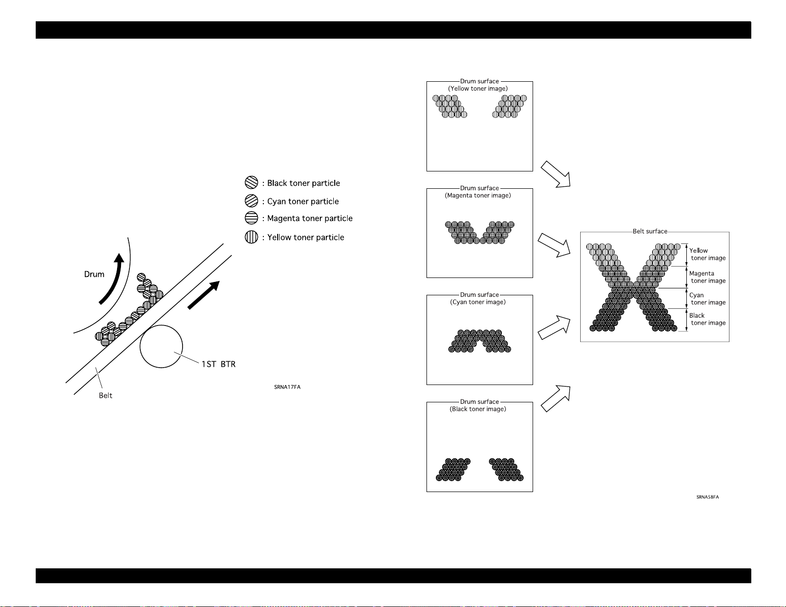
EPSON ColorPage EPL-C8200 Revision A
2.1.3.6 (6) Repeat (Forming a complete full-co lor toner image)
In the Repeat step (forming a complete full-color ton er image), the toner
image of each color on the drum sur face is tr ansferred on to the belt and
is repeated four times, resulting in a complet e full-color toner image on
the belt.
Figure 2-11. Repeat (1)
Figure 2-12. Repeat (2)
Chapter 2 Operating Principles 2-10
Page 74

EPSON ColorPage EPL-C8200 Revision A
2.1.3.7 (7) Second Transfer (Belt → Paper)
In the Second Transfer step, the complete image on the belt is
transferred onto the paper. This is done by supplying voltage to the
Contact Roll, Back Up Roll and 2nd BTR (Second Bias Transfer Roll).
The Contact Roll is a small-diameter metal roll and is in contact with
the Back Up Roll. The Back Up Roll is a conductive roll and is in
contact with the back of the belt. It faces the 2nd BTR where the bel t
is in between. The 2nd BTR is also a conductive roll and is
grounded to the frame via the metal shaft in the center.
The Contact Roll receives n egative high voltage (DC) and gives the
potential to the Back Up Roll. The negative potential given to the
Back Up Roll neutralizes the positive charge on the back of the belt,
and induces a positive charge on the 2nd BTR through the belt and
the paper. The Back Up Roll , belt and 2nd BTR have resi stance an d
the paper functions as a capacitor, resulting in induction of a
positive charge on the 2nd BTR.
When the back of the belt i s neutrali zed, the be lt looses the abi lity t o
retain toner and the complete toner image on the belt i s tr ansferred
onto the paper by the positive charge induced on the 2nd BTR.
The paper (adhering to the belt) is transferred at the correct time so
that the complete toner i mage on the bel t will be tran sferred ont o the
paper in the proper position. When the paper reaches the point the
2nd BTR and the Back Up Roll face each other, the HVPS outputs
high voltage.
Figure 2-13. Second Transfer (1)
Chapter 2 Operating Principles 2-11
Page 75

EPSON ColorPage EPL-C8200 Revision A
In the Repeat step (forming a complete full-color toner image), the
toner image is transferred onto the belt from the drum surface four
times. If, during these transfers, the 2nd BTR is touching the belt,
the toner image created up to this point will be destr oyed. This
means the 2nd BTR must touch (advance to) the belt only after the
complete toner image has been transf err ed onto t he pap er. At other
times, the 2nd BTR must be retracted from the belt. This Advance/
Retract switching operat ion i s ca rried out by the BTR Cam Solenoid .
IBT Surface
By BTR Cam Solenoid
Figure 2-14. Second Transfer (2)
Chapter 2 Operating Principles 2-12
Page 76

EPSON ColorPage EPL-C8200 Revision A
2.1.3.8 (8) Detach
In the detach step, the charge on the paper is neu tralized/removed. Thi s
is done when the Detach Saw gives negative DC voltage to the back
side of the paper.
The Detach Saw receives high voltage from the HVPS.
In the 2nd Transfer step, if there is a positive charge, the toner may
scatter, resulting in a damaged image. To prevent this, the Detach
Saw removes the charge on the paper.
2.1.3.9 (9) Cleaning (Belt)
In the Cleaning (Belt) step, the belt is clea ned aft er the image has been
transferred onto the paper.
The belt has residual toner that was not transf erred onto the paper
in the 2nd Transfer step. The residual toner is scraped off by the
Cleaning Blade (in the Belt Cleaner Assembly) which i s touching the
belt. The scraped toner is transferred through the Auger High
Assembly to the Waste Toner Box.
In the Repeat step (forming a complete full-color toner image), the
toner images are transferred from the drum surface to the belt four
times. If, during these transfers, the Cleaning Blade is touching the
belt, the toner image created up to this point will be destr o yed. So
the Cleaning Bade must touch (advance to) the belt only after the
complete image has been transferred onto the paper. At other
times, the Cleaning Blade must be retracted from the belt. Thi s
Advance/Retreat switching operation is carried out by the Cleaner
Cam Solenoid.
Figure 2-15. Cleaning (Belt)
Chapter 2 Operating Principles 2-13
Page 77

EPSON ColorPage EPL-C8200 Revision A
2.1.3.10 (10) Fusing
In the Fusing step, the toner (image) is fused onto the paper by heat
and pressure.
The complete full-color toner image transferred o nto the paper form
the belt is very fragile, so it must be fused onto the paper by the
Fuser Assembly. The toner is melted with heat from the Heat Roll
and fused under pressure between the Pressure Roll and the Heat
Roll. (The Heat Roll is heated by the H/R Heater.) As auxiliary heat,
the Pressure Roll has a P/R Heater.
When the toner image is fused, the toner becomes adhesive,
causing the paper to adhere to the Heat Roll. To prevent this, the Oil
Roll Assembly supplies Fuser Oil to the Heat Roll. This allows the
paper to be peeled off easily from the Heat Roll.
If the Oil Roll (Oil Roll Assembly) is continuously touching the Heat
Roll, the Fuser Oil may degrade or cause oil spots on the paper. To
prevent this, the Oil Roll touches (advances) the Heat Rol l onl y
when the toner is fused; at other times it is retracted from the Heat
Roll. This Advance/Retract switching operation is carried out by the
Oil Cam Solenoid.
Figure 2-16. Fusing
Chapter 2 Operating Principles 2-14
Page 78

EPSON ColorPage EPL-C8200 Revision A
2.2 Print Data Flow
2.2.1 Data Flow
The print data (electrical signal s) from the printer controller goes
through the processes shown below to form a final print image on the
paper.
(Laser beam)
(On Drum) (Invisib le )
(On Drum) (Visible)
(On Belt)
NOTE:How a two-dimensional image is formed
Scanning the laser beam over the drum’s surface from one side
to the other by switching the laser beam ON and OFF produces
a dot image of one line. A single-color, two-dimensional dot
image is produced by repeating the scanning of the laser beam
for one page. To obtain a full-color image, a single-color image
is generated for each color (YMCBk).
The resolution is determined by the following two factors:
- Main scanning direction: Dots/inch
- Subscanning direction: Number of scanned lines/inch
(On Paper)
(On Paper)
Figure 2-18.
Figure 2-17. Data Flow
Chapter 2 Operating Principles 2-15
Page 79

EPSON ColorPage EPL-C8200 Revision A
2.3 Driver Power Transmission Path
2.3.1 Process Motor Assembly
The rotational force of the Process Motor Assembly is transmi tted to the
Process WDD Assembly and then transmit ted to variou s units as shown
below.
Figure 2-19. Drive Transmission in Process Motor Assembly
Chapter 2 Operating Principles 2-16
Page 80

EPSON ColorPage EPL-C8200 Revision A
2.3.2 P/H Motor Assembly
The rotational force of the P/H Motor Assembly is transmitted to the
Fuser Drive Assembly and P/H Drive Assembly and then to various
units as shown on the right.
Figure 2-20. Drive Transmission in P/H Motor assembly
Chapter 2 Operating Principles 2-17
Page 81

EPSON ColorPage EPL-C8200 Revision A
2.3.3 Dispense Motor Assembly
The Dispense Motor Assembly drives the Auger in the Developer
Assembly. (The Auger supplies the toner from the Toner Cartridge to
the Developer Assembly.)
Figure 2-21.
Drive Transmission in Dispense Motor Assembly
2.3.4 Rotary Motor Assembly
The Rotary Motor Assembly drives the Rotary Frame Assembly.
Figure 2-22.
Transmission in Rotary Motor Assembly
Chapter 2 Operating Principles 2-18
Page 82
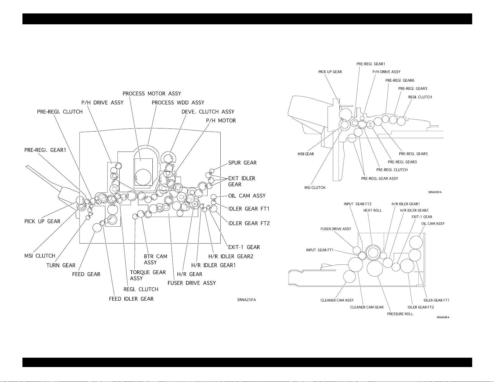
EPSON ColorPage EPL-C8200 Revision A
2.3.5 Gear Layout
Figure 2-23. Gear Layout
Chapter 2 Operating Principles 2-19
Page 83

EPSON ColorPage EPL-C8200 Revision A
2.4 Paper Transportation
2.4.1 Paper Transportation Path (No Option)
NOTE:In this document, Cassettes 1 - 4 are defined as follows:
Cassette 1 (LC1): St andard universal ca ssette
Cassette 2 (LC2): Top tray (Large Capacity Paper Unit / 500-Sheet
Paper Cassette Unit)
Cassette 3 (LC3): Middle tray (Large Capacity Paper Unit)
Bottom tray (500-Sheet Paper Cassette Unit)
Cassette 4 (LC4): Bottom tray (Large Capacity Paper Unit)
Laser Beam
Paper Paths
Sensors fo r detecting paper
Paper feed (C assette 1)
Figure 2-24. Paper Transportation Path Layout
Figure 2-25. Paper Transportation Flow
Chapter 2 Operating Principles 2-20
Page 84

EPSON ColorPage EPL-C8200 Revision A
2.5 Main Components
This section describes the main components and their functions. Each
subsection has a figure illustrating the component and its function. The
major components are listed below.
Paper Tray
Paper Feeder
Multi Sheet Inserter
Paper Transportation
Xerographics-I
Xerographics-II
Development
IBT-I
IBT-II
Fusing-I
Fusing-II
Paper Exit
Frame & Drive
Electrical
Chapter 2 Operating Principles 2-21
Page 85

EPSON ColorPage EPL-C8200 Revision A
2.5.1 Paper Tray
1. Universal Tray
The End Guide can be moved toward the paper feed and holds
the paper stack in place. By moving the End Guide, the moving
force is transmitted to the Sector Gear and the position of the
Tray Size Actuator changes. The Tray Size Actuator pushe s
down (turns on) the Paper Size Switches (on the Size Switch
Assembly). If the Tray Size Actuator position changes, the
combinations of ON/OFF of the four Paper Size Switches
change. The printer recog nizes the paper size from the ON/OFF
combinations.
The Rear Guide Assembly moves in a direct ion perpendi cular to
the direction of the paper feed and holds the paper stack
horizontally.
The Bottom Plate Assembly pushes the paper stack onto the
Feed Roll so that one sheet is pulled out by friction. The Tray N/
F Springs push up the Bottom Plate Assembly.
The bottom of the Bottom Plate Assembly has a magnet that
detects the low paper state (Low Paper Sensor).
The Front Snubber pushes down a corner of the paper so that
only one sheet of paper is pul led out. (Thi s mechanism us es t he
stiffness of the paper to prevent more than one sheet of paper
from being pulled out.)
Figure 2-26. Paper Tray
Chapter 2 Operating Principles 2-22
Page 86

EPSON ColorPage EPL-C8200 Revision A
2.5.2 Paper Feeder
1. Size Switch Assembly
The Size Switch Assembly consists of four Paper Size Switches.
(The switches are directly mounted on the circuit board.) When the
Tray Size Actuator position changes, the ON/OFF combinations of
these switches change and the printer detects the paper size and
the paper tray.
2. Tray No Paper Sensor
From the Tray N/P Actuator posit ion, the printe r detects paper in t he
paper tray.
3. Low Paper Sensor
If the paper in the paper tray gets low, the dist ance between the
Bottom Plate Assembly and the Low Paper Sensor is shortened.
That is, the Magnet behind the Bottom Plate Assembly gets closer;
the Low Paper Sensor detects the magnetism from the Magnet,
determining that the supply of paper is getting low.
4. Feed Solenoid
By controlling the rotation of the Feed Gear, the operation (rotation/
stop) of the Feed Roll Assembly is controlled.
5. Feed Roll Assembly
When the Feed Solenoid is act ivated, the Feed Spring f orc e caus es
the Feed Gear and Feed Idler Gear to mesh. The Feed Roll
Assembly then receives the driving force from the P/H Motor
Assembly and starts rotating, causing the Feed Roll to pull a sheet
of paper from the Paper Tray.
The Feed Gear has a notch that, after it rotates once, dislodges the
Feed Gear and the Feed Idler, causing the Feed Roll Assembly to
stop rotating. This mechanism ensures that only one sheet of p aper
is pulled out.
6. Turn Roll Assembly
The Turn Roll Assembly receives the driving force fr om the P/H
Motor Assembly (via the Main P/H Assembly); it rotates and sends
the paper pulled out from the Paper Tray to the Main P/H Assembly.
Figure 2-27. Paper Feeder
Chapter 2 Operating Principles 2-23
Page 87

EPSON ColorPage EPL-C8200 Revision A
2.5.3 Multi Sheet Inserter (MSI)
1. MSI Assembly
The MSI Assembly feeds paper from the MSI Tray. The MSI
Assembly consists of the MSI Edge Sensor, Pick Up Solenoid, MSI
Clutch and others.
(a) MSI Edge Sensor
The MSI Edge Sensor detects the paper interval (from the
bottom edge of the preceding sheet to the top edge of the next
sheet) in the 2UP mode. I f the paper i nterval is too short, printing
is not done properly in the 2UP mode. If the paper interval
detected by the MSI Edge Sensor is shorter than the
predetermined interval, the system tur ns off the MSI Clutch. This
causes temporarily cuts the driving for ce to the Pick Up Roll s so
that the paper transportation timing is adjusted.
(b) Pick Up Solenoid
The MSI Roll Assembly operation (r otat ion/s top) i s contr oll ed by
controlling the rotation of the Pick Up Cam Gear.
(c) MSI Clutch
(d) MSI Short N/P Sensor
When the MSI N/P Actuator position changes, the MSI Short N/
P Sensor detects paper on the MSI Assembly. The MSI Short N/
P Sensor only functions when the printer controller sends a
signal indicating short paper size (shorter than 150mm) in the
feeding direction.
(e) MSI Long N/P Sensor
The MSI Long N/P Sensor detects paper on the MSI Assembly
by detecting the light reflected from the paper’s surf ace. The
sensor is horizontally attached to the MSI Tray Assembly . It can
detect light from the light emitter which is reflected on the
paper’s surface. (A transparent OHP sheet can be detected by
this method.) The sensor only functions when the printer
controller sends a signal indicating long paper size (150mm or
longer) in the feeding direction.
(g) Retard Pad Assembly
When the Pick Up Roll pulls out a sheet of paper, the friction
between the paper and the Retard Pad Assembly prevents more
than one sheet of paper from being pulled out.
If the paper interval detected by the MSI Edge Sensor is shorter
than the predetermined interval, the paper transportation timing
needs to be adjusted. If the paper interval is too short, the MSI
Clutch temporarily cuts off the driving force to the Pick Up Rolls
transportation timing. (to adjust the paper interval) and corrects
the paper.
(h) Pick Up Roll
The MSI Roll Assembly receives the force from the Pick Up
Solenoid and the MSI Clutch and starts ro tat ing and t he Pick Up
Roll pulls out a sheet of paper. Both the Pick Up Gear and the
Pick Up Cam Gear have a notch that, after rotating once,
disengages the Pick Up Cam Gear and MSI Gear, thus causing
the MSI Roll Assembly to stop rotating. This mechanism
ensures that only one sheet of paper is pulled out.
Chapter 2 Operating Principles 2-24
Page 88
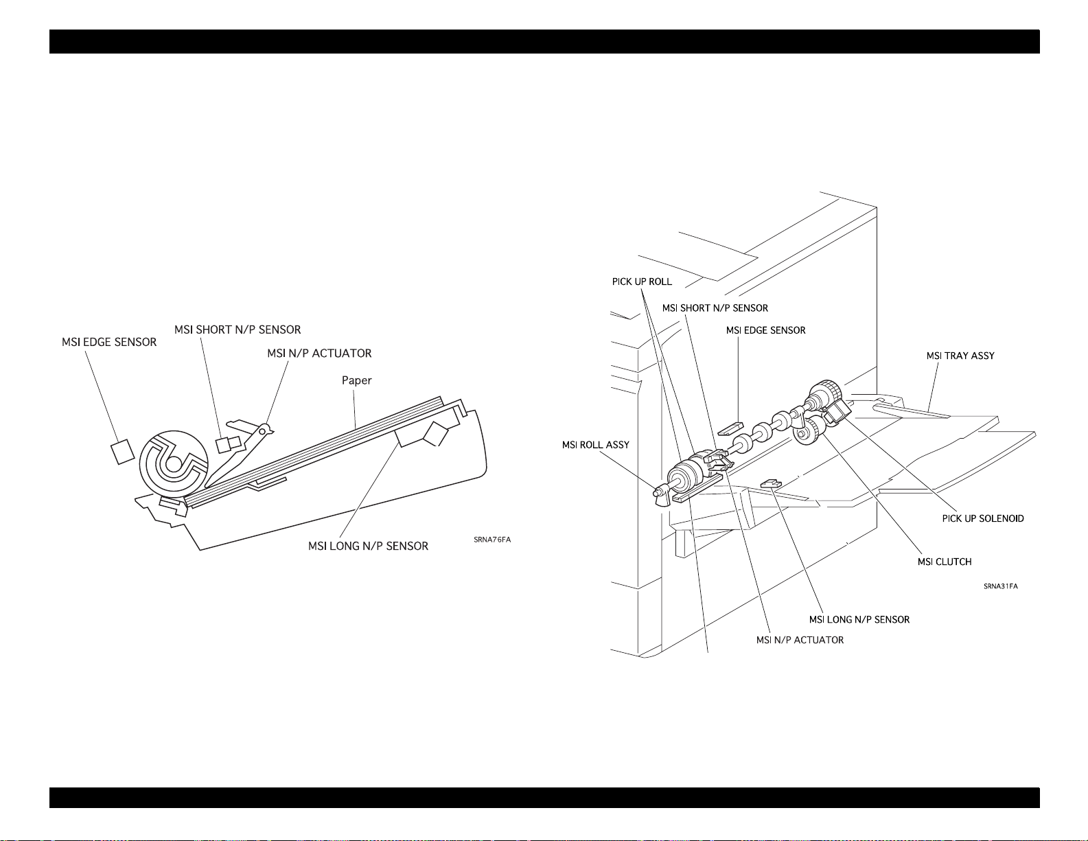
EPSON ColorPage EPL-C8200 Revision A
2. MSI Tray Assembly
The MSI Tray Assembly hold the paper stack on the MSI Assembly.
RETARD PAD ASSY
Figure 2-28. Multi Sheet Inserter
Chapter 2 Operating Principles 2-25
Page 89

EPSON ColorPage EPL-C8200 Revision A
2.5.4 Paper Transportation
1. Main P/H Assembly
The Main P/H Assembly consists of the following components:
Pre-Registration Roll Assembly
Registration Clutch
Pre-Registration Clutch
Registration Brake Clutch
Registration Sensor
Front OHP Sensor
Rear OHP Sensor
Registration Brake Clutch
Registration Metal Roll
Registration Rubber Roll
(a) The Registration Metal Roll and Registration Rubber Roll pull
out the paper in synchronization with the IBT Belt Assembly
timing so that the paper will be positioned properly for the
complete toner image on the IBT Belt Assembly to be correctly
transferred onto the paper.
(b) Pre-Registration Roll Assembly transfers paper from the paper
tray or the MSI Assembly onto the Registration Metal Roll and
Registration Rubber Roll. Until the top of the paper reaches the
Registration Metal Roll and Registration Rubber Roll and until
those rolls start rotating, the Pre-Registration Roll Assembly
keep transferring the rear part of the paper by making a paper
loop and correcting the skew at the top of the paper.
(c) The Registration Brake Clutch controls (applies the bra ke to) the
Registration Metal Roll.
When the top of the paper reaches the Registration Metal Roll
and Registration Rubber Roll it forms a loop. However, hard
paper (such as an OHP sheet) may go through the Registration
Metal Roll and the Registration Rubber Roll without mak ing a
loop. By turning on the Registration Brake Clutch , the
Registration Metal Roll and the Registration Rubber Roll are
constricted and the paper cannot go through—and that causes a
paper loop.
(d) The Registration Clutch transmits the driving force from the P/H
Motor Assembly to the Registration Metal Roll and Registrat ion
Rubber Roll so that the paper and the IBT Belt Assembly are
properly positioned for a secondary image transf er.
(e) The Pre-Registration Clutch transmits the driving force from the
P/H Motor Assembly to the Pre-Registration Roll Assembly.
(f) The Registration Sensor detects when the top of the paper has
reached the Registration Metal Roll and the Registration Rubbe r
Roll. To determine the paper size, the system detects the
bottom edge of the paper. (The paper size is determined by the
system keeping track of the time from when the Registration
Clutch is turned on to when the Registration Sensor detects no
paper.)
(g) The printer detects the front and back of an OHP sheet* fro m the
combined results of the Front OHP Sensor and the Rear OHP
Sensor. (For more details, see “7.3 OHP Side Detection Control ”
in Section 10.)
*The printer can use EPSON Color Laser Transparencies
(S041175, S041174) only.
(h) The resistor and the capacitor installed on the front of the Main
P/H Assembly maintain the potential of the Registra tion Metal
Roll at the time of image transfe r. If the Registr ation Metal Roll i s
directly grounded, the potential of th e pape r escapes to the
ground via the Registration Metal Roll. This means that the
paper will not have enough potential for an image to be
transferred correctly.
Chapter 2 Operating Principles 2-26
Page 90

EPSON ColorPage EPL-C8200 Revision A
Figure 2-29. Paper Transportation
Chapter 2 Operating Principles 2-27
Page 91
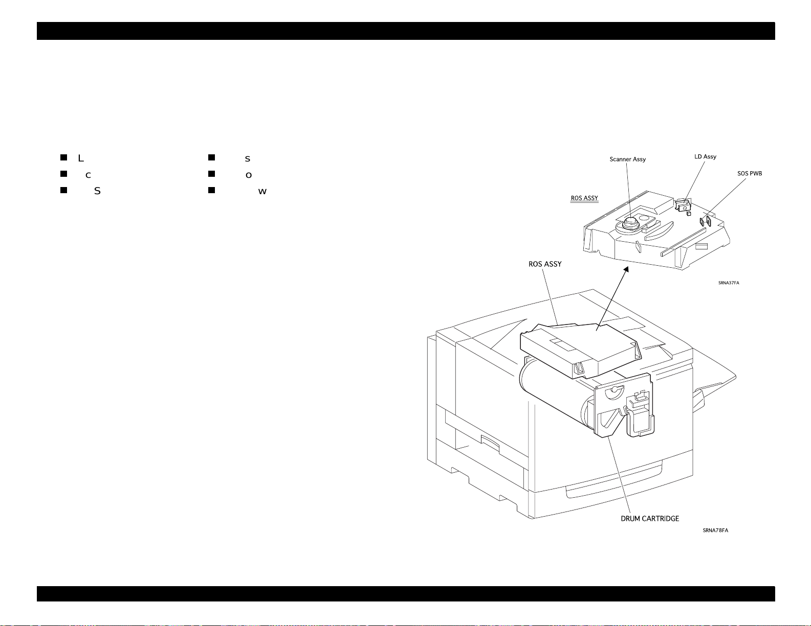
EPSON ColorPage EPL-C8200 Revision A
2.5.5 Xerographics I
1. ROS Assembly
The ROS (Raster Output Scanner) Assembly outputs laser beam to
form an electrostatic latent image on the drum’s surface. The ROS
Assembly consists of the following components.
LD Assembly
Scanner Assembly
SOS PWB
(a) The image data is sent to the ROS Assembly as electrical
signals. (High and low voltage indicates dat a in the el ectrical
signals.). The LD (Las er Diode) Assembly converts the electrical
signals (of the image data) to optical signals (laser beam ON/
OFF). If the laser light quantity changes, a proper el ectrostatic
latent image cannot be obtained. To obtain a stable laser
amount, the LD Assembly (monitor circuit) always monitors and
controls the LD output (LD Power). This is called the APC (Auto
Power Control). For details, see Section 2.7. 4.2.
(b) The Scanner Assembly consists of the Scanner Motor and
Polygon Mirror. (The Scanner Motor rotates at a constant
rotational speed; the Polygon Mirror is on the ro tational axis of
the Scanner Motor.). The laser beam output from the LD
Assembly is projected onto the Polygon Mirror. The Polygon
Mirror has 12 reflecting surfaces; as the Scanner Motor rotates,
the reflection angle of the laser beam changes. This change
causes the laser beam to scan the drum’s surface in the drum
axis direction. One reflecting surface of the mirror scans one
line.
Lens
Mirror
Window
(d) To form a proper electrosta tic latent image on the drum sur face ,
the laser scanning timing and the writing timing of the i ma ge
data must be coordinated. The SOS Sensor on the SOS PWB
(Start Of Scan Printed Wiring Board) converts the laser beam
into electrical signals ( SOS signals) which detect the initial
position (scan start position) in each line that the laser will scan.
(c) The laser beam reflected by the Polygon Mirror arrives on the
drum surface via the lens, mirror and window. The lens corrects
any aberrations and the mirror ensures light passage. The
window prevents any foreign objects from enter ing the ROS.
Figure 2-30. Xerographics
I
Chapter 2 Operating Principles 2-28
Page 92

EPSON ColorPage EPL-C8200 Revision A
2.5.6 Xerographics II
1. Drum Cartridge
The Drum Cartridge consists of the Xero. Cartridge, Waste Toner
Box and others.
(a) The Xero. Cartridge consists of the Drum, BCR, Cleaning Blade,
and others.
• The Drum is an aluminium cylinder on which the OPC
(Organic Photoconductor) material has been painted. The
OPC material is photoconductive so a laser scanning the
drum’s surface forms an electrostatic latent image on the
drum. (Photoconductive: A photoconductive material is an
insulator (holds potential in the dark) that, when it receives
light, becomes conductive and the potential is grounded.)
• The BCR uniformly charges the drum surface in the Charge
step in the print process.
• The Cleaning Blade scrapes off the residual t oner particles in
the First transfer process in the print proces s.
(b) The Waste Toner Box collects the toner scraped off the drum’s
surface by the Cleaning Blade and the other toner sent by the
Auger High Assembly (the toner scraped off from the IBT Belt
Assembly by the Belt Cleaner Assembly).
5. ADC Sensor Assembly
The ADC Sensor Assembly consists of the ADC Sensor, ADC
Solenoid and others.
(a) ADC Sensor
The ADC (Automatic Density Control) Sensor detects the toner
density of the image on the drum’s surface or toner densi ty of
the drum’s surface itself, and sends the density data to the
Process Control Unit.
(For more details, see Section 2.7.5.)
(b) ADC Solenoid
If the ADC Sensor light emitter or receptacle is dirty with toner ,
the sensor cannot detect the toner density of the image or the
drum’s surface. So, the ADC Sensor light emitter and receptacle
are cleaned by the cleaning lever when the ADC Solenoid is
activated.
2. Erase Lamp Assembly
The Erase Lamp Assembly emits a light onto the drum’s surface to
remove the residual charges remaining from the previous Ch arge
process.
3. Waste Toner Sensor
The Waste Toner Sensor detects when the Waste Toner Box is full
of discarded toner.
4. Toner Box Sensor
The Toner Box Sensor detects the Waste Toner Box.
Chapter 2 Operating Principles 2-29
Page 93

EPSON ColorPage EPL-C8200 Revision A
Figure 2-31. Xerographics II
Chapter 2 Operating Principles 2-30
Page 94

EPSON ColorPage EPL-C8200 Revision A
2.5.7 Development
1. Used Cartridge Sensor
The Used Cartridge Sensor detects whether the toner car tr idge is
new or used for the color in each toner cartridge. In the trickle
development method, the used developer is collected in the
collection chamber in th e Toner Cartridge. A reflection seal has
been pasted on a wall inside the chamber; when collected and
accumulated in the collection chamber, the used developer covers
the reflection seal. The Used Cartridge Sensor is a reflection type
photo sensor. If it detect s a refl ected l ight f rom the Toner Cart ri dges
for each color, it determines that the used developer has not filled
up the collection box, meaning that the Toner Cartridge is still new.
If it does not detect a reflected light from the Toner Cartridge, the
Toner Cartridge is old.
2. Cartridge Sensor
The Cartridge Sensor is a reflection type photo sensor. It detects a
reflection light from the Toner Cartridges. If it detects a reflected
light, it determines that the Toner Cartridge has been mounted. If it
does not detect a reflected light, it dete rmines that the Toner
Cartridge has not been mounted.
(a) The three Augers in the Developer Assembly:
• Supplies toner from the Toner Cartridge to the Developer
Assembly.
• Agitates the developer in the Developer Assembly.
• Supplies the developer from the Developer Assembly to the
Magnet Roll.
(b) The Magnet Roll has the following functions:
• Attracts the carrier particles.
• Forms an even developer layer.
• Supplies toner to the drum.
(c) The Trimmer Blade is positioned so that a gap is maintained
between the Magnet Roll and the Trimmer Blade; it forms an
even developer layer on the Magnet Roll.
(d) The Tracking Roll maintains a gap between the drum and the
Magnet Roll.
5. The Toner Cartridges (Y, M, C and Bk) have toner (including
carriers) and collect the used developer (carriers).
3. Rotary Sensor
The Rotary Sensor detects the home position of the Rotary Frame
Assembly. The Developer control is done based on the home
position.
(For more details, see “7.8 Developer Control.”)
4. Developer Assembly Y, Developer Assembly M, Developer
Assembly C, Developer Assembly Bk
The major components of each of these Developer Assemblies (Y,
M, C and Bk) are the Augers, Magnet Roll, Trimmer Blade and
Tracking Roll.
Chapter 2 Operating Principles 2-31
Page 95

EPSON ColorPage EPL-C8200 Revision A
Figure 2-32. Development
Chapter 2 Operating Principles 2-32
Page 96
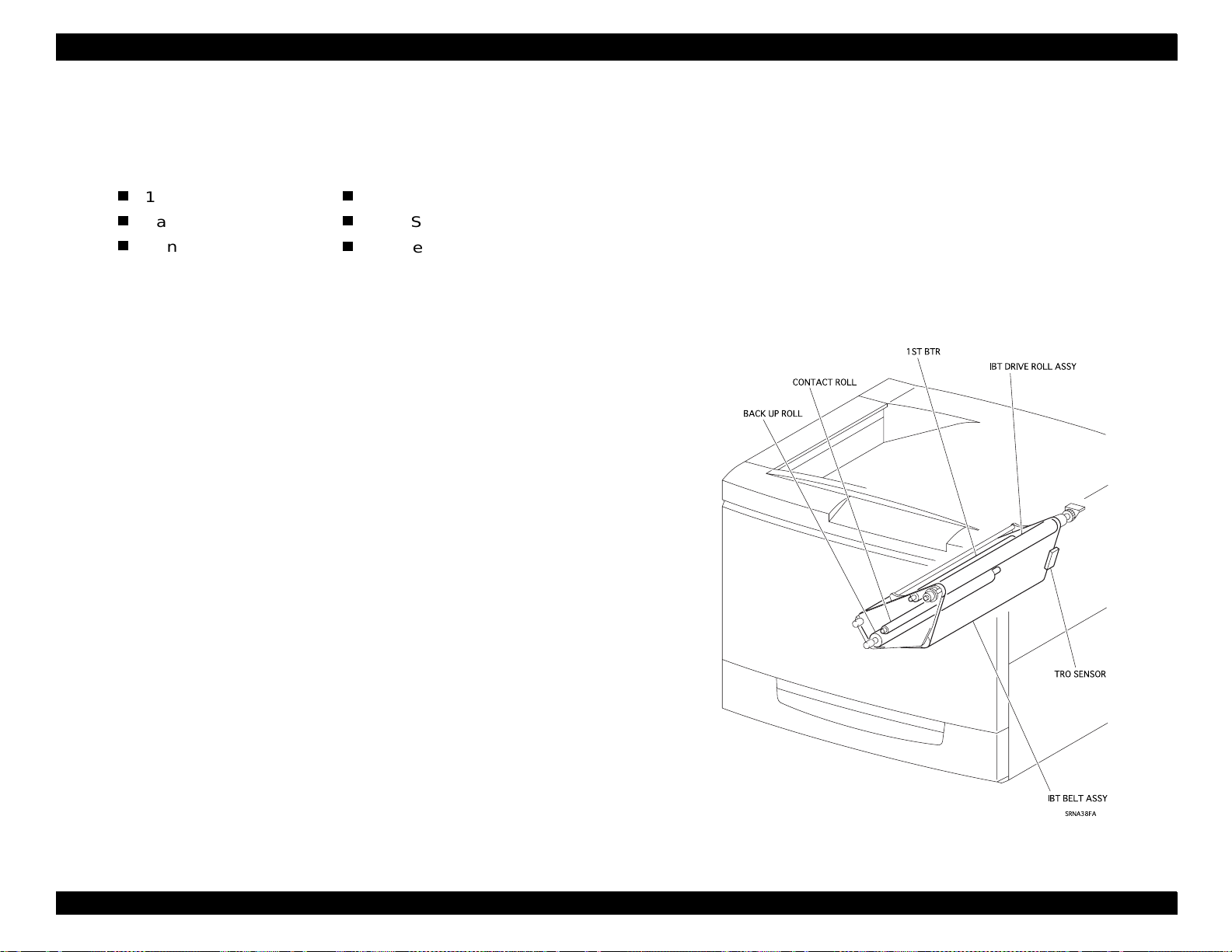
EPSON ColorPage EPL-C8200 Revision A
2.5.8 IBT-I
1. Transfer Assembly
The Transfer Assembly consists of the following components:
1st BTR
Back Up Roll
Contact Roll
(a) The 1st BTR (First Bias Transfer Roll) is a conductive roll, fa cing
the drum. (The IBT Belt Assembly i s in the middle.) The 1st BTR
transfers the toner image on the drum to the IBT Belt Assembly.
(b) The Contact Roll is a metal roll (small diameter). It is in contact
with the Back Up Roll and provides the 2nd transfer voltage to
the Back Up Roll.
(c) The Back Up Roll is a conductive roll, facing (from inside) the
2nd BTR. (The IBT Belt Assembly is in the middle). When the
paper passes through, the Back Up Roll provides the 2nd
transfer voltage to the paper from the inside of the IBT Belt
Assembly.
(d) The IBT Drive Roll Assembly transfers the driving force of the
Process Motor Assembly to the IBT Belt Assembly. (The
Process Motor Assembly receives the driving force from the
Process WDD Assembly.)
IBT Drive Roll Assembly
TRO Sensor
IBT Belt Assembly
Process Motor runs, the transfer ref erence marks are alt ernately
detected. This prevents the image from being transf erred onto
the same location on the belt all the time—something that leads
to image degradation.
(f) A one-color toner image on the drum is transferred onto the I B T
Belt Assembly. This process is repeated four times (for four
colors). At the end, a 4-color overlaid toner image has been
formed on the IBT Belt Assembly. When the complete toner
image is formed on the belt, the 2nd BTR provides negative
transfer voltage to the belt and the bel t tr ansfers t he image (of 4color toner) onto the paper (2nd transfer).
(e) The silver marks (TRO marks) is pasted at the rear end of the
IBT Belt Assembly. This is because t he toner images transfer red
onto the IBT Belt Assembly must match precisely. The TRO
Sensor detects this mark every time the IBT Belt Assembly
makes one rotation. When the sensor detects the mark, the
system waits for a predetermined period and then generates a
TRO signal (which indicates the reference point and the image
transfer reference point to form an image.) The IBT Belt
Assembly has two TRO marks. As a result, every time the
Figure 2-33. IBT-I
Chapter 2 Operating Principles 2-33
Page 97

EPSON ColorPage EPL-C8200 Revision A
2.5.9 IBT-II
1. 2nd BTR Assembly
The 2nd BTR Assembly consists of the following components:
2nd BTR
2nd BTR Cleaner
Detach Saw (Charge Removable board)
(a) The 2nd BTR (Second Bias Transfer Roll) is a conductive roll. It
faces the Back Up Roll from outside the belt. (The IBT Belt
Assembly is in the middle.) The 2nd BTR induces the transfer
voltage from the voltage provided by the Back Up Roll and
transfers the toner image on the IBT Belt Assembly onto the
paper (2nd transfer).
(b) The 2nd BTR Cleaner is in contact with the 2nd BTR and
scrapes off the toner from the surface of the 2nd BTR. (The
scraped toner is collected in the toner chamber in the 2nd BTR
Assembly.)
(c) The Detach Saw (Charge Removal Plate) provides the charges
on the back of the paper and neutralizes/removes the charges
on the paper.
(a) The Cleaning Blade moves forward to the IBT Belt Assembly
after the 2nd transfer process and scrapes off the remaining
toner on the belt.
(b) The Auger transfers the scraped toner to the Auger High
Assembly.
(The Auger High Assembly transfers the toner to the Waste
Toner Box.)
2. BTR Cam Solenoid
The BTR Cam Solenoid transfers the drive f orce from t he P/H Motor
Assembly, via the P/H Drive Assembly, to the 2nd BTR Cam
Assembly, and controls the advance/retract movement of the 2nd
BTR Assembly. (Advance: The 2nd BTR Cleaner moves forward to
the IBT Belt Assembly; Retract: The 2nd BTR Cleaner moves away
from the IBT Belt Assembly.)
3. BELT Cleaner Assembly
The Belt Cleaner Assembly consists of the following compo nents:
Cleaning Blade
Auger
Figure 2-34. IBT-II
Chapter 2 Operating Principles 2-34
Page 98

EPSON ColorPage EPL-C8200 Revision A
2.5.10 Fusing-I
1. Fuser Assembly
The Fuser Assembly fuses the toner on the paper with heat and
pressure, and transfers the paper in and out, to and from the Fuser
Assembly. The Fuser Assembly consists of the Main Fuser
Assembly and the Fuser Tray Assembly.
Main Fuser Assembly
The Main Fuser Assembly consists of the Heat Roll, Pressure
Roll, H/R Heater, P/R Heater, Temperature Sensor Assembly
and others.
• The Heat Roll is a cylindrical metal roll with a rubber layer on
the surface. It applies heat to the paper to fuse the toner onto
the paper.
• The Pressure Roll is a cylindrical metal roll with the rubber
layer on the surface. It applies heat and pressure on the
paper to fuse the toner on the paper.
• The H/R Heater is a halogen lamp in which hea ting coils have
been sealed. (The heating coils provide the heat source for
the Heat Roll.) The H/R Heater is installed inside the Heat
Roll and heats the Heat Roll to the fusing temperature.
• The P/R Heater is a halogen lamp in which heating coils h ave
been sealed. (The heating coils provide the heat source for
the Pressure Roll.) The P/R Heater is installed inside the
Pressure Roll and heats the Pressure Roll to the fusing temperature.
• The Temperature Sensor Assembly is a thermistor sensor. It
always touches the Heat Roll and detects the temperature on
the Heat Roll’s surface. (A thermi stor is an element that
changes its resistance by temperature. ) From the detected
temperature, the Temperature Sensor Assembly controls the
ON/OFF of the H/R Heater and P/R Heater and prevents
overheating (primary overheating prevention mechanism).
• The Thermostat is connected (in series) to the power supply
circuits of the H/R Heater an d P/R Heat er. If the primary overheating prevention mechanism of the Temperature Sensor
Assembly fails, the contact point in the Thermostat opens,
shutting off the power supply to the H/R Heater and P/R
Heater (secondary overheating prevention mechanism).
• The Thermal Fuse is connected in series to the power supply
circuits of the H/R Heater and P/R Heater. If the primary and
secondary overheating prevention mec hanisms fai l, t he Thermal Fuse is melted by t he heat, shutting off the power supply
to the H/R Heater and P/R Heater (tertiary overheating prevention mechanism).
• The Fuser Exit Sensor detects a paper pass from the position
change of the Fuser Exit Actuator.
• The H/R Finger prevents paper from being rolled into the
Heat Roll.
• The P/R Finger prevents paper from being rolled into the
Pressure Roll.
Chapter 2 Operating Principles 2-35
Page 99
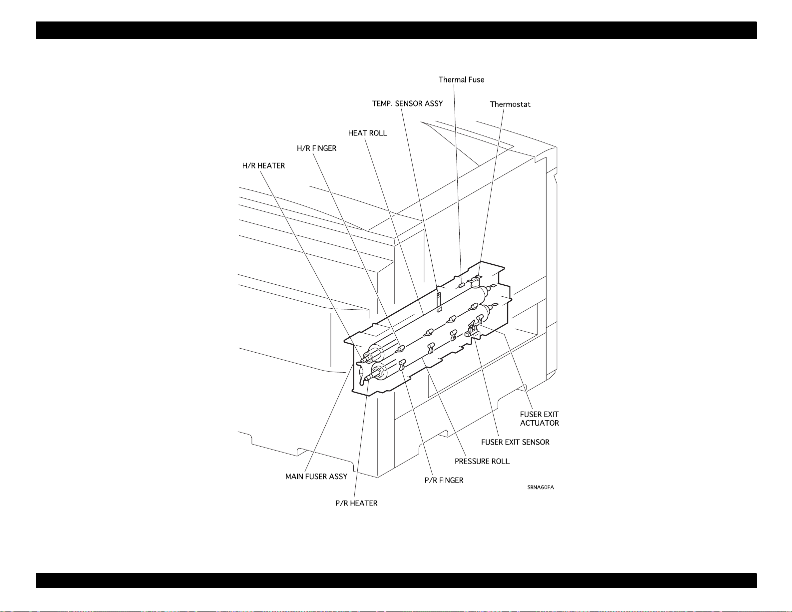
EPSON ColorPage EPL-C8200 Revision A
Figure 2-35. Fusing-I
Chapter 2 Operating Principles 2-36
Page 100

EPSON ColorPage EPL-C8200 Revision A
2.5.11 Fusing-II
1. Fuser Assembly
The Fuser Assembly fuses the toner on the paper with heat and
pressure and transfers the paper to and from the Fuser Assembly.
The Fuser Assembly consists of the Main Fuser Assembly and
Fuser Tray Assembly.
(a) Fuser Tray Assembly
The Fuser Tray Assembly consists of the Fuser In Sensor, the
Oil Cam Solenoid and the Exchange Solenoid. It transfers the
paper to and from the Main Fuser Assembly.
• Fuser In Sensor
The Fuser In Sensor detects a paper pass status from the
position change of the Fuser In Actuator . (It detects the paper
tip based on the detection timing of the Fuser Exit Sensor.)
• Fuser Chute Fan
The Fuser Chute Fan pulls down the paper to the Fuser
Paper Guide and the Horizontal Chute. This is necessary to
position the paper correctly so that the paper is properly
transferred to the Fuser Main Assembly.
• Cleaner Cam Solenoid
The Cleaner Blade in the Belt Cleaner Assembly needs to
touch the IBT Belt Assembly only immediately after the 2nd
toner transfer. It must not touch the belt at any other time. (If
the Cleaning Blade is touching the IBT Belt Assembly while
the toner image is being formed on the IBT Belt Assembly,
the toner image is damaged.)
The Cleaner Cam Solenoid transfers the driving force from
the P/H Main Assembly, via the P/H Drive Assembly, to the
Cleaner Cam Assembly and the Cleaner Cam Guide, and
controls the advance/retract operation of the Belt Cleaner
Assembly. (Advance: The Cleaning Blade moves forward to
the IBT Belt Assembly; Retract: The Cleaning Blade moves
away from the IBT Belt Assembly.)
• O il Cam Solenoid
If the Oil Roll in the Oil Roll Assembly is constantly touching
the Heat Roll, the Fuser Oil may degrade and oil stains may
appear on the paper. The Oil Roll needs to touch the Heat
Roll only during the fusing operation; at other times, the Oil
Roll must remain separated from the Heat Roll.
The Oil Cam Solenoid transfers the driving force from the P/H
Main Assembly, via the P/H Drive Assembly, to the Oil Cam
Assembly, and controls the advance/retract operations of the
Oil Roll Assembly. (Advance: The Oil Roll of the Oil Roll
Assembly moves forward to the Heat Roll; Retract: The Oil
Roll moves away from the Heat Roll.)
• Exchange Solenoid
After fusing, the paper may be ejected face up or face down.
The Exchange Solenoid switches the Exchange Chute and
controls the paper ejection modes.
• Exit-1 Roll Assembly
The Exit-1 Roll Assembly transfers the fused paper from the
Fuser Main Assembly.
2. Oil Roll Assembly
The Oil Roll Assembly has an Oil Roll in which Fuser Oil has been
impregnated. The Oil Roll in the Oil Roll Assembly follows the Heat
Roll rotation and applies the Fuser Oil evenly onto the Heat Roll
surface. The Fuser Oil prevents the following:
• Paper from being rolled into the Heat Roll.
• Heat Roll wear caused by contact with the Temperature Sensor Assembly and the H/R Fingers.
Chapter 2 Operating Principles 2-37
 Loading...