

Page 1
EPSON TERMINAL PRINTER
EPL-9000
SERVICE MANUAL
EPSON
Page 2
NOTICE
AN
rights reserved. Reproduction of any part of this manual in any form whatsoever without
SEIKO
EPSON’S
express
written permission is forbidden.
The contents of this manual are
All efforts have been made toensuretheaccuracyof the contents of this manual. However, should
any errors be detected, SEIKO EPSON would greatly appreciate being informed of them.
The above notwithstanding SEIKO EPSON can assume no responsibility for any errors in this
manual or the consequence thereof.
Epson and Epson ESCPare registered trademarks and Epson
Corporation.
Speedo,
CG
Univers is a registered trademark of Linotype AG and / or its subsidiaries.
Antique Olive is a trademark of Fonderie Olive.
Albertus is a trademark of Monotype Corporation
Coronet is a trademark of Ludlow Industries (UK) Ltd.
Arial and Times New Roman are registered trademarks of Monotype Corporation
Fontware, FaceLift, Swiss, and Dutch are trademarks of BitStream Inc.
Times and CG Omega are registered trademarks of Miles, Inc.
subjcxts
to change without notice.
ESCP2
plc.
isa tradernarkof Seiko Epson
plc.
GeneraZNotice:
trademarks of their respective
Other product
Copyright @ 1994 by SEIKO EPSON CORPORATION
mrnes
carnpanies.
used herein are for identication purposes only and maybe
Nagano,
Japan
-i-
Page 3

PRECAUTIONS
Precautionary notations throughout
damage to equipment.
DAIVGIER
WAWW4G
The precautionary measures itemized below should always be observed whenperforrning repair/
maintenance procedures.
Signals a precaution which, if ignored, could result in serious or fatal personal injury.
Great caution should be exercised in performing procedures preceded by DANGER
Headings.
Signals a precaution which, if ignored, could result in damage to equipment.
the
text are categorized relative to 1) personal injury and 2)
DANGER
1.
ALWAYS DISCONNECT THE PRODUCT FROM BOTH THE POWER SOURCE AND
PERIPHERAL DEVICES PERFORMING ANY MAINTENANCE OR REPAIR PROCEDURE.
NO WORK SHOULD BE PERFORMED ON THE UNIT BY PERSONS UNFAMILIAR WITH
2.
BASIC SAFETY MEASURES AS DICTATED FOR ALL ELECTRONICS TECHNICIANS IN
THEIR LINE OF WORK.
WHEN PERFORMING TESTING AS DICTATED WITHIN THIS MANUAL, DO NOT
3.
CONNECT THE UNITTOA POWER SOURCE UNTIL INSTRUCTED TO DO SO. WHEN
THE POWER SUPPLY CABLE MUST BE CONNECTED, USE EXTREME CAUTION IN
WORKING ON POWER SUPPLY AND OTHER ELECTRONIC COMPONENTS.
WARNING
1.
REPAIRS ON EPSON PRODUCT SHOULD BE PERFORMED ONLY BY AN EPSON
CERTIFIED REPAIR TECHNICIAN.
2.
MAKE CERTAIN THAT THE SOURCE VOLTAGE IS THE SAME AS THE RATED VOLTAGE, LISTED ON THE
HAS A PRIMARY AC RATING DIFFERENT FROM AVAILABLE POWER SOURCE, DO
NOT CONNECT IT TO THE POWER SOURCE.
ALWAYS VERIFY THAT THE EPSON PRODUCT HAS BEEN DISCONNECTED FROM
3.
THE POWER SOURCE BEFORE REMOVING OR REPLACING PRINTED CIRCUIT
BOARDS AND/OR INDIVIDUAL CHIPS.
4.
IN ORDER TO PROTECT SENSITIVE MICROPROCESSORS AND CIRCUITRY, USE
STATIC DISCHARGE EQUIPMENT, SUCH AS ANTI-STATIC WRIST STRAPS, WHEN
ACCESSING INTERNAL COMPONENTS.
REPLACE MALFUNCTIONING COMPONENTS ONLY WITH THOSE COMPONENTS
5.
BY THE MANUFACTURE; INTRODUCTION OF SECOND-SOURCE
NONAPPROVED COMPONENTS MAY DAMAGE THE PRODUCT AND VOID ANY
APPLICABLE EPSON WARRANTY.
SEIUAL
NUMBER/RATING PLATE. IF THE EPSON PRODUCT
ICS
OR OTHER
- ii -
Page 4
SAFETY INFORMATION
‘lhis
printer is a page printer which operates by means of a laser. There is no possibility of danger from
the laser, provided the printer is
operated
accordrng
to the instructions
in this manual provided.
Since radiation emitted by the
cannot escape from the machine during any phase of user operation.
For Europe
For Denmark
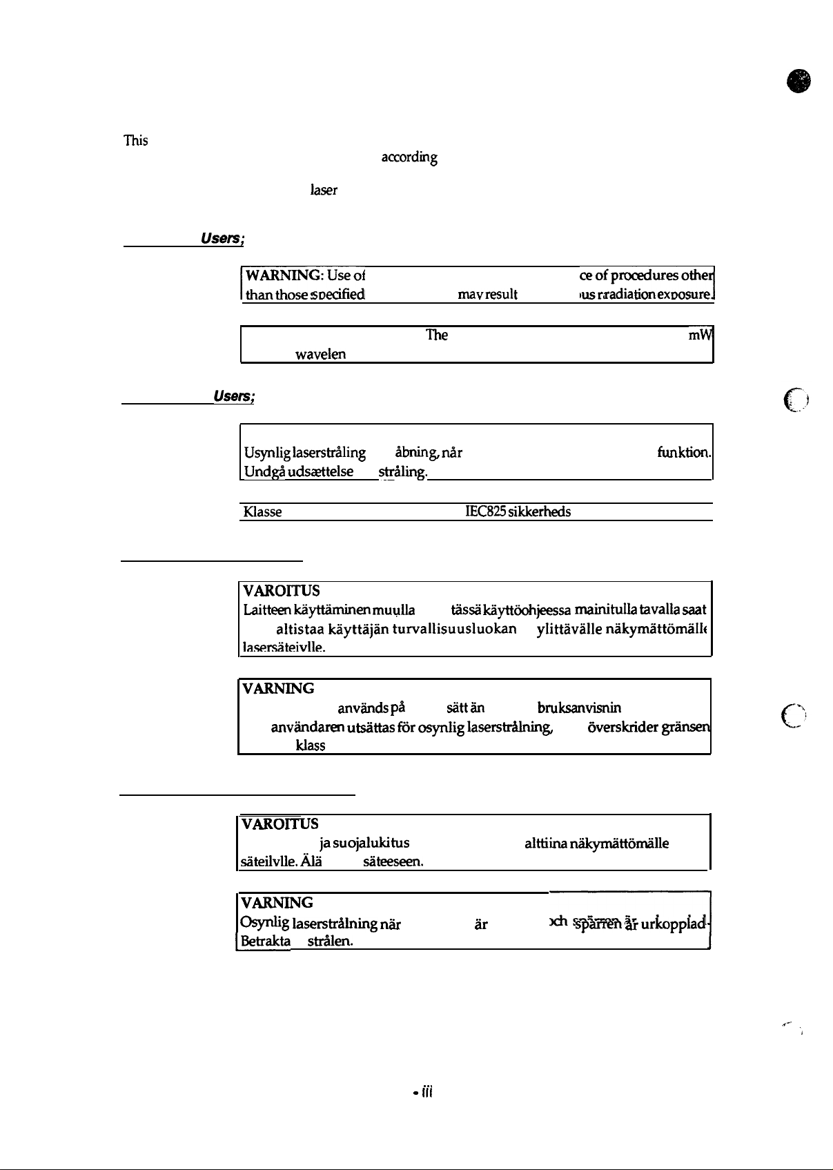
For Finland, Sweden Users;
Usem;
WARNING: Use of controls, adjustments or performan
r-”-”””-”--
than those
This is a semiconductor laser.
and the
Usem;
ADVARSEL
Usynlig Iaserstri?ding
Undg5 uds~telse
Klasse
laser
is completely confined within protective housings, the laser beam
sm?cified
wavelen
1 laser produkt der opfylder
in this manual
The
gth is 780 nm.
ved
iibnin~ n~r
for
strWng.
rnavresult
maximum power of the laser diode is 5
sikkerhedsafbrydere er ude af
IEC825 sikkerheds
in hazardous
kravene.
‘ofp-w=otiel
radlationexoosure
m~
funktion.
I
VAROITUS
Laitteen lciiyttlhinen muulla
taa
altistaa kayttajan turvallisuusluokan
Ia.sersiiteivlle.
VARMNG
Orn apparaten
kan
anv~dam utsiittas K5r osyrdig Iaserstr&nin&
for laser
For Finland, Sweden Service People
VAROITUS
Avattaessa
siiteilvlle. Ala
VARNING
-g
~Betrakta
klass
laserstriilning niir
ej
anviinds pi%
1.
ja suojalukitus
katso
stxfden.
siiteeseen.
kuin
t.iis.sii
k@t60hjeessa
1
ylittavalle nakymattomalI[
annat
denna del & oppnad och
siitt iin
i denna
ohitettaessa olet
bruksanvisnin
som
alttiina niikymiittonulille
7
rnainitulla tavalla mat
g specificerats,
Wdcrider griinsen
laser
sparren ar Urkopplad
I
. . .
-
Ill -
*..
L.’
‘,
Page 5
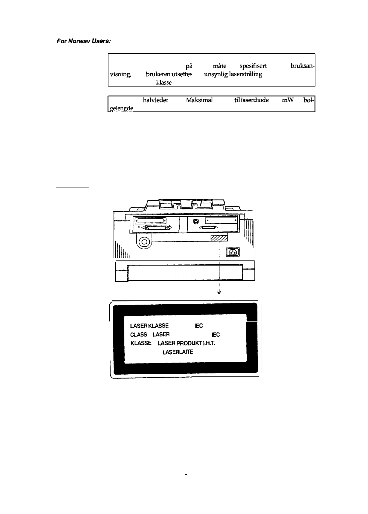
ADVARSEL
Dersom apparatet brukes pa annen
visning,
grensen for laser
kan
bmkeren utsettes
klasse
1.
for
unsynlig laserstn!ding
rn&e
enn
spesifisert
som overskrider
i denne
bruksan-
Dette er en
gelengde
Laser
[Label
A
For Europe
Safety Labels
on rear printer case]
laser safety labels is attached on the outside of the printer shown below.
halvleder
er 780 nm.
laser.
Maksimal
effeckt
til Iaserdiode
lllh-
er 5
mW
og
brd-
r
-
I
IASER MASSE
CIJLSS
1
IJ$SER
KIA!3SE
LUOKAN 1
1
IJiSER PRODUKT I.H.T.
IASER14TE
1
NACH
PRODUCT TO
- iv -
IEC
825
IEC
825
IEC 825
1
Page 6
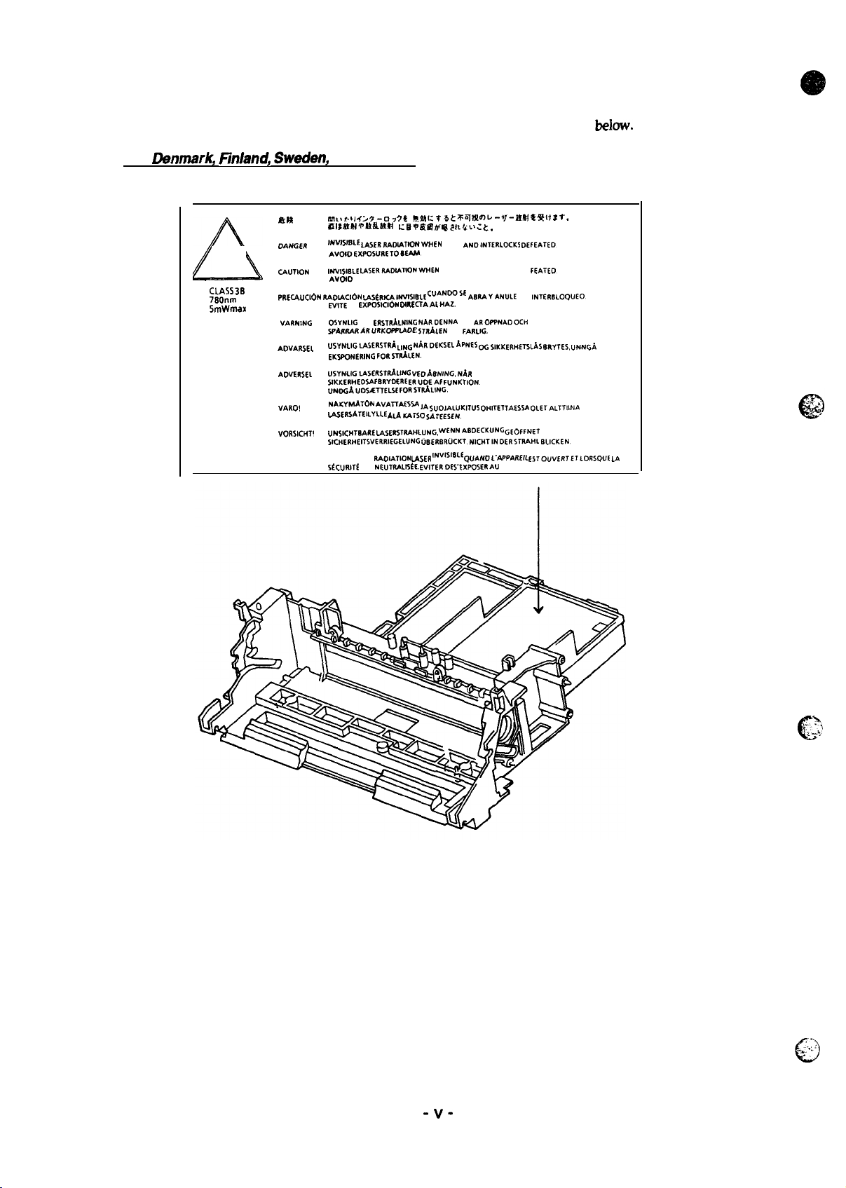
[Label inside printer]
The following laser safety label will be attached inside the printer as shown
For
Danmark, finland, Swadan,
km
DANGm
*
CLASS 3B
780nm
5mWmax
~UTION
PREOWCldN RAOIAC16N LA5tRlCAlW0181E C1.1AN005E ABRA~ANuLE
VARNING
AOVARSEL
AOVERSEL
VARO! NFWYNEAToN AVA~A6w JA
VORSICHT!
ATTENTION
and Norway
rkll~t:
~1 4 i
9-07 ~ t
.Rf.hl:
i$lstm+nkils!!
INVISISIIE
IASERJIAOW_WEN
AvOIOEXP05URE T08EAM
NEV018LE
LASMTFWXA7WNWWEN OPEN AND INTERLOCKS DE fEATEO.
AVLNO
EXPOSURE TOMAM.
EV17E
IA
EXPOSIC16N DIREmAAL HAZ.
OSYNLIG LAS fRSTRALNING
SPARRARARUIWWEADE~
uSYNLIGLASERSTR~ LING N~RDEKSELkWESOG
EKSPONERING FoRSTRALEN.
USYNLIGLASERSTRAL[* VEDA8NING.
SIKKERHEO$AF8RYDERE
UNDGAUOSATTELSC
LASERSAIEILYLLE Ati=rSo sArEE5EN.
UNSICH18ARE LASERSTIL4HLUNG,
SICHERHEITSVERRIEGEIUNG CIBERLTRUCK?.
EMISSION DE
StCURITt
RAOIATION
EST NEUTRALIStE.
7 * ~~~~~~
+l=mvctm
WE? tttit~: t.
OPEN AND1NTERLOCK5 D6FEATED.
NARDENNA
5TRALEN
ERUDEAF
FOR$TRALING.
SUOIALUKITU5
wENNABDECKUNG
USER
lNVf118Lf QUANOL’AppAREIL
WIIERDE
DEL
ARoWNADOCH
AR
FARL!G.
SIKKERHETsLAS
NAR
FUNUTION.
OHITE1TAES5A
NICHTIN
S’EXPOSERAU RAYON LASER.
-+f-~* *
Qtf ~ f.
EL
INTERBLOQLIE13
8RYTES.
OLEIALTTIINA
GEo6pNET
UND
OERSTRAHL BLICKEN.
ES70UWRTETLOR$QUE LA
below.
UNNG~
-v-
~:.:>.l
.=
c
-./,’
Page 7

PREFACE
This manual describes functions, theory of electrical and mechanical operations, maintenance, and repair
of EPL-9000.
The instructions and procedures included herein are intended for the experience repair technician, and
attention should be given to the precautions on the preceding page. The chapters are organized as
follows:
CHAPTER 1. GENERAL DESCRIPTION
Provides a general product overview, lists specifications, and illustrates the main components of the printer.
CHAPTER 2. OPERATING PRINCIPLES
Describes the theory of printer operation.
CHAPTER 3. DISASSEMBLY AND ASSEMBLY
Includes a step-by-step guide for product disassembly and assembly.
CHAPTER 4. ADJUSTMENTS
Includes a step-by-step guide for adjustment.
CHAPTER 5. TROUBLESHOOTING
Provides Epson-approved techniques for adjustment.
CHAPTER 6. MAINTENANCE
Describes preventive maintenance techniques to service the equipment.
APPENDIX
Describes connector pin assignments, circuit diagrams, circuit board component layout.
The contents of this manual are subject to change without notice.
- vi -
Page 8

REVISION SHEET
Revision
Rev.
A
Isaue
Date
Augusl
I
5, 1994
Revision Page
1s
issue
I
I
:’
. . .
.
c
- vii -
c“
,, . . . .
[.
~..-
“
Page 9

TABLE OF CONTENTS
CHAPTER 1.
CHAPTER 2.
CHAPTER 3.
CHAPTER 4.
CHAPTER 5.
CHAPTER 6.
APPENDIX
GENERAL DESCRIPTION
OPERATING PRINCIPLES
DISASSEMBLY AND ASSEMBLY
ADJUSTMENTS
TROUBLESHOOTING
MAINTENANCE
-
Vlll
.m.
-
Page 10
Chapter 1 General Description
Table of Contents
1.1
FEATURES
1.2 SPECIFICATIONS
1.2.1
1.2.2
1.2.3
1.2.4
1.2.5
1.2.6
1.2.7
1.2.8
1.2.9
1.3 INTERFACE SPECIFICATIONS
1.3.1 Parallel interface. . . . . . . . . . . . . . . . . . . . . . . . . . . . . . . . . . . . . . . . . .
1.3.2 Serial Interface . . . . . . . . . . . . . . . . . . . . . . . . . . . . . . . . . . . . . . . . . . . 1-17
1.3.3 Optional LocalTalk Interface . . . . . . . . . . . . . . . . . . . . . . . . . . . . . . . . .
1.4
Basic Specifications. . . . . . . . . . . . . . . . . . . . . . . . . . . . . . . . . . . . . . . . . 1-3
Electrical Specifications. . . . . . . . . . . . . . . . . . . . . . . . . . . . . . . . . . . . . . 1-5
Reliability Specifications . . . . . . . . . . . . . . . . . . . . . . . . . . . . . . . . . . . . . 1-5
Environmental Conditions for Operation (Including Imaging Cartridge). . 1-6
Environmental Conditions for Storage and Transportation . . . . . . . . . . . 1-6
Applicable Standards. . . . . . . . . . . . . . . . . . . . . . . . . . . . . . . . . . . . . . . . 1-6
Specification for Consumable (Imaging Cartridge) . . . . . . . . . . . . . . . . . 1-7
Physical Specifications . . . . . . . . . . . . . . . . . . . . . . . . . . . . . . . . . . . . . . 1-7
Software Specifications. . . . . . . . . . . . . . . . . . . . . . . . . . . . . . . . . . . . . . 1-8
1.3.1.1 Compatibility Mode of Parallel lntetface. . . . . . . . . . . . . . . . . .
1.3.1.2 Reverse Mode.... . . . . . . . . . . . . . . . . . . . . . . . . . . . . . . . . . .
OPERATING INSTRUCTIONS
1.4.1 Control Panel.... . . . . . . . . . . . . . . . . . . . . . . . . . . . . . . . . . . . . . . . . .
1.4.2
1.4.3 Sewice
SelecType
Functions. . . . . . . . . . . . . . . . . . . . . . . . . . . . . . . . . . . . . . .
Mode.... . . . . . . . . . . . . . . . . . . . . . . . . . . . . . . . . . . . . . . . . .
1.4.3.1 Hexadecimal Dump Mode. . . . . . . . . . . . . . . . . . . . . . . . . . . . .
1.4.3.2 Language Setting Mode . . . . . . . . . . . . . . . . . . . . . . . . . . . . . .
1.4.3.3 Factory Service Mode. . . . . . . . . . . . . . . . . . . . . . . . . . . . . . . .
1.4.3.4 EEPROM Format Mode . . . . . . . . . . . . . . . . . . . . . . . . . . . . . .
1.4.4 Display ofMessages. . . . . . . . . . . . . . . . . . . . . . . . . . . . . . . . . . . . . . .
1.4.4.1 Status Messages. . . . . . . . . . . . . . . . . . . . . . . . . . . . . . . . . . . .
1.4.4.2 Error Messages.. . . . . . . . . . . . . . . . . . . . . . . . . . . . . . . . . . . .
1.4.4.3 Warning Messages. . . . . . . . . . . . . . . . . . . . . . . . . . . . . . . . . .
1.4.5
PrinterSharing. . . . . . . . . . . . . . . . . . . . . . . . . . . . . . . . . . . . . . . . . . . .
1.4.5.1 Port Fixed Mode.. . . . . . . . . . . . . . . . . . . . . . . . . . . . . . . . . . .
1.4.5.2 AutoSense Mode. . . . . . . . . . . . . . . . . . . . . . . . . . . . . . . . . . .
1.4.6 Emulation Mode Switch Functions. . . . . . . . . . . . . . . . . . . . . . . . . . . . .
1.4.6.1 Emulation Switch by
1.4.6.2 Intelligent Emulation Switch . . . . . . . . . . . . . . . . . . . . . . . . . . .
1.4.7 Bi Resolution Improvement Technology . . . . . . . . . . . . . . . . . . . . . . . .
1.4.8 Optional Memory. . . . . . . . . . . . . . . . . . . . . . . . . . . . . . . . . . . . . . . . . .
SPL . . . . . . . . . . . . . . . . . . . . . . . . . . . . .
1-1
1-3
1-11
1-11
1-11
1-13
1-19
1-20
1-20
1-22
1-25
1-25
1-25
1-26
1-26
1-27
1-27
1-27
1-28
1-29
1-29
1-30
1-31
1-31
1-31
1-32
1-33
1.5
MAIN COMPONENTS
1.5.1
1.5.2
1.5.3
1.5.4
1.5.5
1.5.6
1.5.7
C135 MAIN Board. . . . . . . . . . . . . . . . . . . . . . . . . . . . . . . . . . . . . . . . .
C82326*
Control panel... . . . . . . . . . . . . . . . . . . . . . . . . . . . . . . . . . . . . . . . . . .
MCU PWB Board. . . . . . . . . . . . . . . . . . . . . . . . . . . . . . . . . . . . . . . . . .
LVPS Unit . . . . . . . . . . . . . . . . . . . . . . . . . . . . . . . . . . . . . . . . . . . . . . .
HVPS Board . . . . . . . . . . . . . . . . . . . . . . . . . . . . . . . . . . . . . . . . . . . . .
ROS Unit. . . . . . . . . . . . . . . . . . . . . . . . . . . . . . . . . . . . . . . . . . . . . . . .
l/F Board (Optional LocalTalk Module). . . . . . . . . . . . . . . . .
1-34
1-35
1-36
1-36
1-37
1-37
1-38
1-38
Page 11
1.5.8 Fusing Unit. . . . . . . . . . . . . . . . . . . . . . . . . . . . . . . . . . . . . . . . . . . . . . .
1.5.9 Drive
1.5.10 Imaging Catiridge. . . . . . . . . . . . . . . . . . . . . . . . . . . . . . . . . . . . . . . . .
Unit. . . . . . . . . . . . . . . . . . . . . . . . . . . . . . . . . . . . . . . . . . . . . . . .
List of Figures
1-39
1-39
1-39
e
Figure 1-1. Exterior View of the EPL-9000 . . . . . . . . . . . . . . . . . . . . . . . . . . . .
Figure 1-2. Printable Area. . . . . . . . . . . . . . . . . . . . . . . . . . . . . . . . . . . . . . . . . 1-5
Figure 1-3. Compatibility Mode Signal Timing. . . . . . . . . . . . . . . . . . . . . . . . . 1-11
Figure l-4.
Figure 1-5. Negotiation
Figure 1-6. Data Transfer Timing Chart. . . . . . . . . . . . . . . . . . . . . . . . . . . . . . 1-15
Figure 1-7. Termination Timing Chart. . . . . . . . . . . . . . . . . . . . . . . . . . . . . . . 1-16
Figure 1-8. Interrupt Timing Chart. . . . . . . . . . . . . . . . . . . . . . . . . . . . . . . . . . 1-16
Figure 1-9. Control Panel . . . . . . . . . . . . . . . . . . . . . . . . . . . . . . . . . . . . . . . . 1-20
Figure
Figure 1-11. Auto
Figure 1-12. Emulation Switch by SPL . . . . . . . . . . . . . . . . . . . . . . . . . . . . . . 1-31
Figure 1-13. Intelligent Emulation Switch . . . . . . . . . . . . . . . . . . . . . . . . . . . . 1-31
Figure 1-14. Effect of
Figure 1-15.
Figure 1-16. Component Layout . . . . . . . . . . . . . . . . . . . . . . . . . . . . . . . . . . . 1-34
Figure 1-17. C135 MAIN Board. . . . . . . . . . . . . . . . . . . . . . . . . . . . . . . . . . . . 1-35
Figure 1-18. C8232&k
Figure 1-19. Control Panel . . . . . . . . . . . . . . . . . . . . . . . . . . . . . . . . . . . . . . . 1-36
Figure 1-20. MCU PWB Board . . . . . . . . . . . . . . . . . . . . . . . . . . . . . . . . . . . .
Figure 1-21. LVPS Unit. . . . . . . . . . . . . . . . . . . . . . . . . . . . . . . . . . . . . . . . . .
Figure 1-22. HVPS Drive. . . . . . . . . . . . . . . . . . . . . . . . . . . . . . . . . . . . . . . . .
Figure 1-23.
ParalleI
1-10. Port Fixed Mode . . . . . . . . . . . . . . . . . . . . . . . . . . . . . . . . . . . . . 1-29
ROS Unit. . . . . . . . . . . . . . . . . . . . . . . . . . . . . . . . . . . . . . . . . . .
interface State Switch Diagram . . . . . . . . . . . . . . . . . . . . 1-14
Timing Chart . . . . . . . . . . . . . . . . . . . . . . . . . . . . . . . 1-15
Sense Mode. . . . . . . . . . . . . . . . . . . . . . . . . . . . . . . . . . . . 1-30
BiRITech. . . . . . . . . . . . . . . . . . . . . . . . . . . . . . . . . . . . 1-32
RITech
Adjustment. . . . . . . . . . . . . . . . . . . . . . . . . . . . . . . . . . . 1-32
l/F Board. . . . . . . . . . . . . . . . . . . . . . . . . . . . . . . . . . .
Figure 1-24. Fusing Unit . . . . . . . . . . . . . . . . . . . . . . . . . . . . . . . . . . . . . . . . .
Figure 1-25. Drive Unit . . . . . . . . . . . . . . . . . . . . . . . . . . . . . . . . . . . . . . . . . .
Figure 1-26. Imaging Cartridge. . . . . . . . . . . . . . . . . . . . . . . . . . . . . . . . . . . .
1-1
1-36
1-37
1-37
1-38
1-38
1-39
1-39
1-39
@
. .
,.
.
List of Tables
Table
Table 1-2. Paper Feed Methods . . . . . . . . . . . . . . . . . . . . . . . . . . . . . . . . . . . .
Table 1-3. Paper Types. . . . . . . . . . . . . . . . . . . . . . . . . . . . . . . . . . . . . . . . . . .
Table 1-4. Usability of Special Paper . . . . . . . . . . . . . . . . . . . . . . . . . . . . . . . . 1-4
Table l-5. Electrical Specifications . . . . . . . . . . . . . . . . . . . . . . . . . . . . . . . . . .
Table 1-6. Differences
Emulation. . . . . . . . . . . . . . . . . . . . . . . . . . . . . . . . . . . . . . . . . . . . . . . . . . . . . .
Table 1-7.
Table 1-8. Parallel Interface Pin Assignments . . . . . . , . . . . . . . . . . . . . . . . . .
Table 1-9. Parallel Interface Pin Assignments. . . . . . . . . . . . . . . . . . . . . . . . .
Table l-10. Serial Interface Pin Assignments . . . . . . . . . . . . . . . . . . . . . . . . .
Table 1-11. LocalTalk Interface Pin Assignments. . . . . . . . . . . . . . . . . . . . . .
Table 1-12.
Table 1-13. Factory Service Mode . . . . . . . . . . . . . . . . . . . . . . . . . . . . . . . . .
Table 1-14. Status Messages . . . . . . . . . . . . . . . . . . . . . . . . . . . . . . . . . . . . .
Table 1-15. Error Messages . . . . . . . . . . . . . . . . . . . . . . . . . . . . . . . . . . . . . .
Table 1-16. Warning Messages. . . . . . . . , . . . . . . . . . . . . . . . . . . . . . . . . . . .
1-1,
Options for EPL-9000. . . . . . . . . . . . . . . . . . . . . . ..............1-2
Buitt-in
Fonts . . . . . . . . . . . . . . . . . . . . . . . . . . . . . . . . . . . . . . . . . .
SelecType
between EPSON GU2 and
Functions . . . . . . . . . . . . . . . . . . . . . . . . . . . . . . . . . .
GIJ2
in the HP LaserJet
1-3
1-4
1-5
4
1-8
1-8
1-12
1-13
1-17
1-19
1-22
1-26
1-27
1-27
1-28
Page 12
EPL-9000
Service Manual
1.1 FEATURES
General Description
The EPSON@ EPL-9000
electr~photographic
is a non-impact page printer that combines a semi-conductor laser with
technology. This printer is small and light, and features high-speed,
high-resolution printing. Maintenance is very easy as a result of various built-in diagnostic
functions. The main features are:
No ozone
L1
Printing speed — 8 ppm (pages per minute) (A4 or letter size)
Q
Resolution — 600/300
c1
Small footprint
D
Easy maintenance
c1
HP@
cl
c1
c1
c)
cl
LaserJet@ 4 emulation mode
45 built-in scalable fonts (35
ESC/P 2’”
emulation
High-performance controller (the controller’s CPU is a 19.2 MHz
Bi Resolution Improvement Technology
jagged edges from images and characters on 600
Optional
tl
EPSON Micro Gray Technology
la
EPSONScript
Level 2 mode, refines gray scale printing to be comparable to printing on a
Ct
Small and low-cost optional LocalTalk
2 MB standard RAM and up to 64 MB RAM with the addition of
Q
Bidirectional parallel interface
Q
High-speed serial communication rate of 57.6K bps
c1
High-speed parallel communication rate of approximately 400 KB/second
D
A multi-user, multi-emulation mode
D
ES
c1
(Intelligent Emulation Switch) allows switching between
dpi
(dots per inch)
Intellifonts
and 10 TrueType fonts)
(BiRITech) r#fh&
dpi
and 300
the print quality by eliminating
dpi
Level 2 (PostScript@ compatible) module
(EMGTech),
TM
interface module
which is
availabie
EPSONScript
SPARKlite (MB86930))
printing.
when using
EPSONScript
12~dpi
optioml SIMMS
mode and another
printer
mode
SPL (Shared Printer Language) enables switching of the printer mode by command
c1
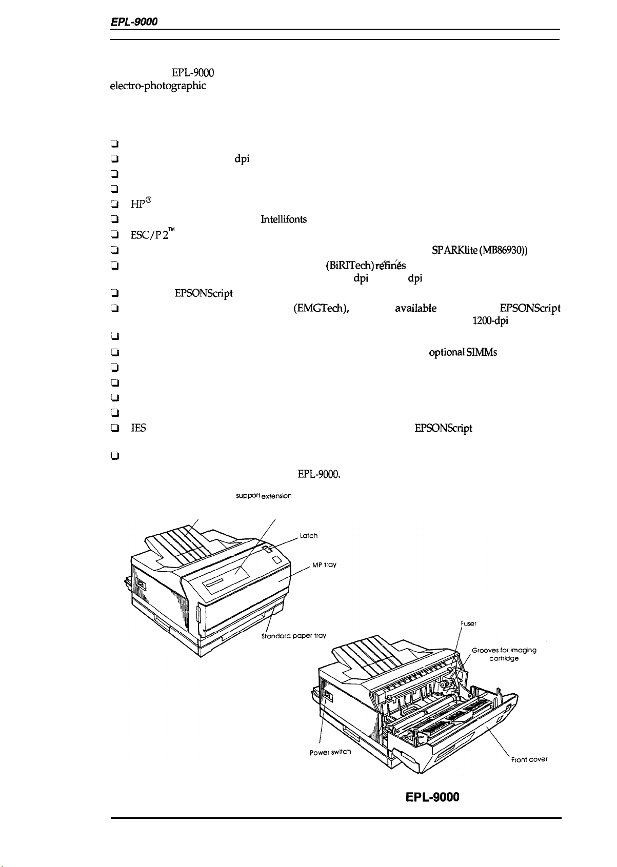
Figure 1-1 shows an exterior view of the
Paper
sup~fl eflens~n
/
EPL-9000.
, Control panel
Rev. A
Figure 1-1. Exterior View of the
EPL-9000
1-1
Page 13
General Description
EPL-~
Service
Mhnual
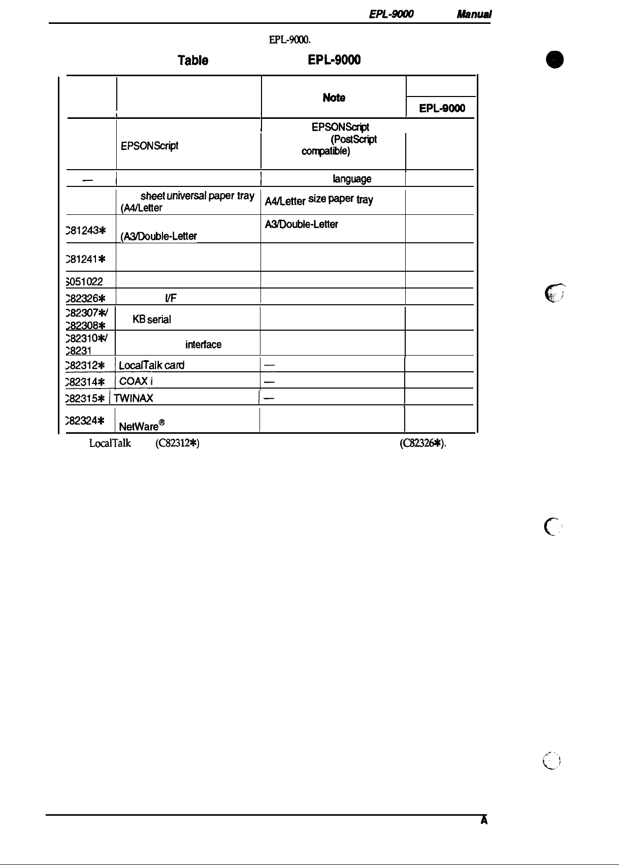
Table 1-1 lists the optional units available for the
Cat. No.
X3209*
Description
I
EPSONScript
Table
Level 2 Module
1-1. Options for
EPL-9(XXI.
I
I
Supports
Level 2 mode
Level 2
commands
—
81242
‘
*
;8124*
;81241 *
;051022
282326*
282307M
;82a8*
I
Local language ROM
250
sheet t.m~ersal wr W
(A4/Letter
250
(A3/Double-Letter
size)
sheet universal paper tray
size)
Lower paper cassette unit
Imaging cartridge
LocalTalk
32 KB
flF
Module
seril
interface card
I
Supports local
1
A~etter size pqer tray
A3Double-Letter
tray
Lower paper cassette unit
(No include paper cassette)
Toner cartridge
—
—
EPL-9000
EPSONScr@
(PostSc@
compatitde)
fonts and
fanguage
size paper
Machine Type
EPL-9000
1
I
Yes
fonts Yes
1
Yes
Yes
Yes
Yes
Yes
Yes
28231 OW
;8231
, *
32
KB
~82312X LocalTalkcard
:82314X
*
COAX interface card
;82315X I TWINAX
>82=4*
Ethernet interface card for
NetWare@
Note:
LodTalk
card
parallel
intetface
card
interface card
(C82312*)
cannot be used with LocalTalk I/F module
—
:
1—
—
Yes
Yes
Yes
Yes
1
Yes
(C8232649.
1-2
Rev.
A
Page 14
EPL-9000
Service Manual
1.2 SPECIFICATIONS
General Description
This section provides statistical data for the
1.2.1
Basic Specifications
Printing method:
Resolution: 600/300 dpi
Printing speed:
First printing time:
Warm-up time:
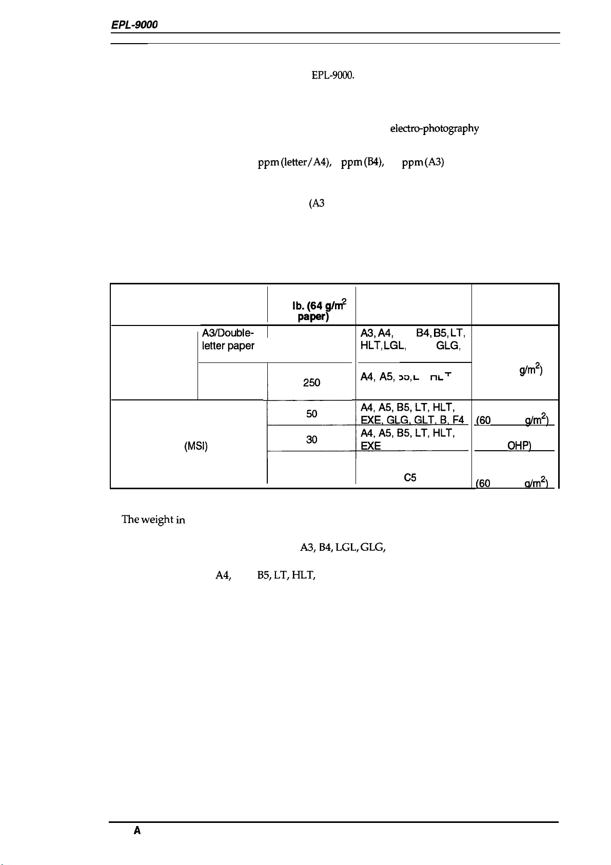
Paper supply: See Table 1-2.
Laser beam scanning and dry
8
ppm (letter/A4),
18.9 seconds (A4 cassette feed)
19.1 seconds (Letter cassette feed)
25.0 seconds
Less than 120 seconds
(at rated current and 20° C (68° F) temperature)
EPL-9000.
(A3
Table 1-2. Paper Feed Methods
Capacity
Paper Supply
Standard built-in
paper tray or
optional
paper cassette
unit
Manual feeder
lower
;;:::;:;
cassette
A4/Letter
paper
cassette
(MSI)
I
M
(17
l~:grj/m
250
5
5
ppm (B4),
cassette feed)
~
)
4.3
A3, A4,
HLT, LGL,
B, F4
A4, A!5,
EXE
lntemational-B5, MON,
C1O, DL,
electro-photography
ppm (A3)
Paper Size
A5,
EXE,
l?= ‘ T “ 7
xl, L
C5
by cassette feed
B4, B5, LT,
GLG,
I ,
I-IL
I ,
Usage Thickness
16 to 24 lb.
(60
16 to 24 lb.
(60
Special paper
[label,
Envelopes made
of 16 to 28 lb.
(60
(Ream Weight)
to
90
g/m2)
to 135
to 105
a/m2)
OHP)
a/m2)
Notes:
1.
The weight in
weigh; 1 g/m2 = 0.2659763 lb.
2. The printer can use manual feed for
paper by hand.
3. When inserting
horizontal.
pounds (lb) is determined
A4,
AS,
B5, LT, HLT,
by
how much 500 sheets cut to 17x 22 inches would
B4,
A3,
LGL, GLG,
EXE, and GLT size
B and
F4 size paper, if user supports
papers, keep the longer side
Rev.
A
1-3
Page 15
Genersl L)eswiption
EPL-$tX# ~
“
ManuaJ
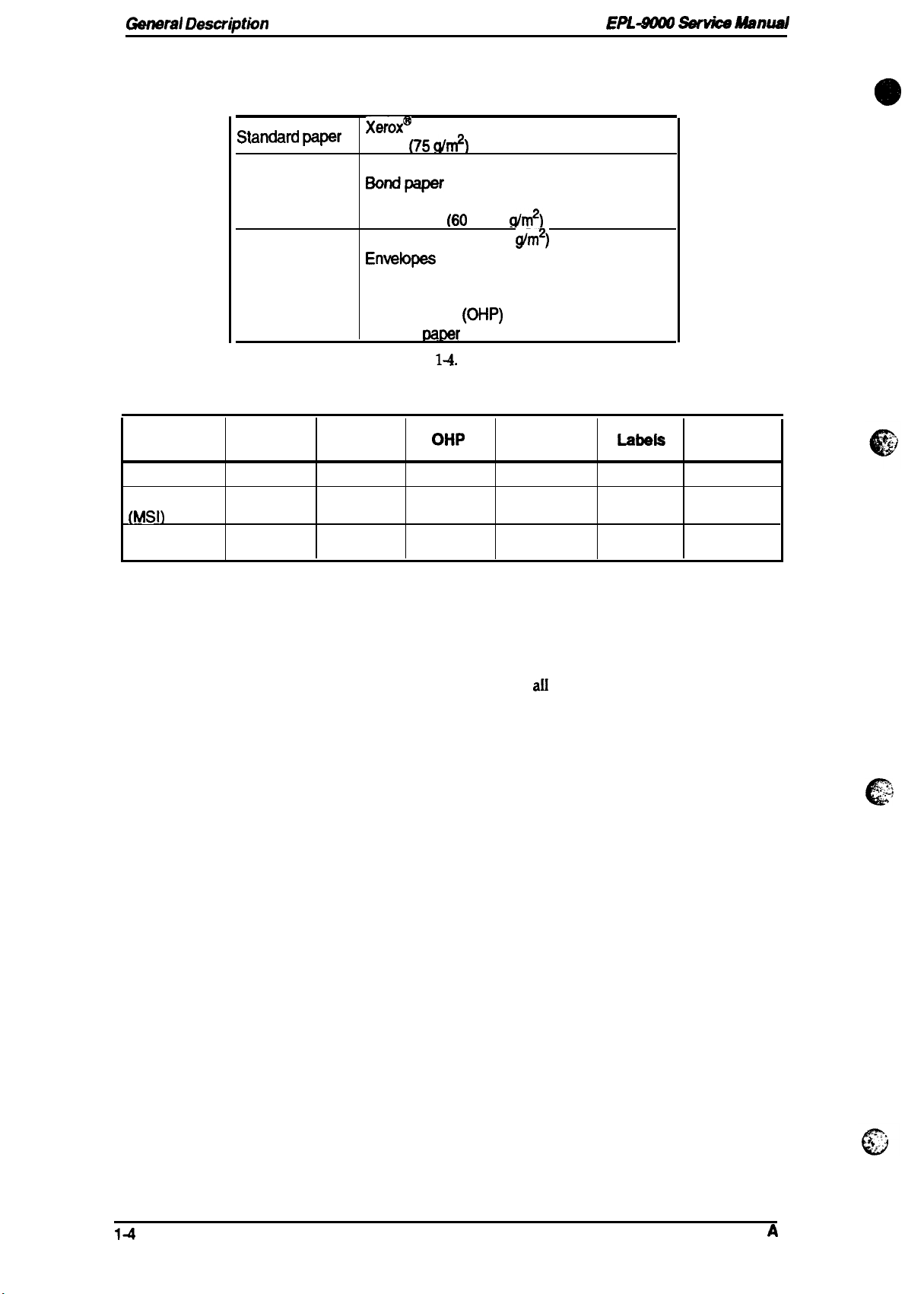
Paper types:
‘tatid ‘r
Normal paper
Special paper
Usability of special papers:
Table 1-4. Usability of Special Paper
Input
Paper tray
Manual feed
(MSI)
Envelope
cassette
Standard
paper
R
R
N
See Table 1-3.
Table 1-3. Paper Types
Xerox@
20 lb.
Recycled paper
16 to 24 lb.
Card stock (90 to 135
Envefopes
Labels
Letterhead
Transparency
Colored
Normal
paper
R
R P
N
4024 DP paper
(75 dr#)
Regular photocopier paper
Bondpaper
(60
to 90
(ah#’)
(OHP)
sheets
rxmer
See Table
1-4.
OHP Envelopes
P N
N
@m2)
P
P
Labefs Card Stock
P
P P
N N
N
R: Reliable feeding and good image quality.
P: Possible, but better avoided.
N: Not supported.
Paper size range:
Paper feed alignment and direction: Center alignment for
Paper ejection:
Output tray capacity:
98 mm (3.87 inches) to 297 mm (11.7 inches)
140 mm
Face down
250 sheets (standard paper)
(5.5
inches) to
432 mm (17
aII
sizes
(Width)
inches) (Length)
$’;
c
14
Rev.
A
Page 16
EPL-9000
Service Manual
General Description
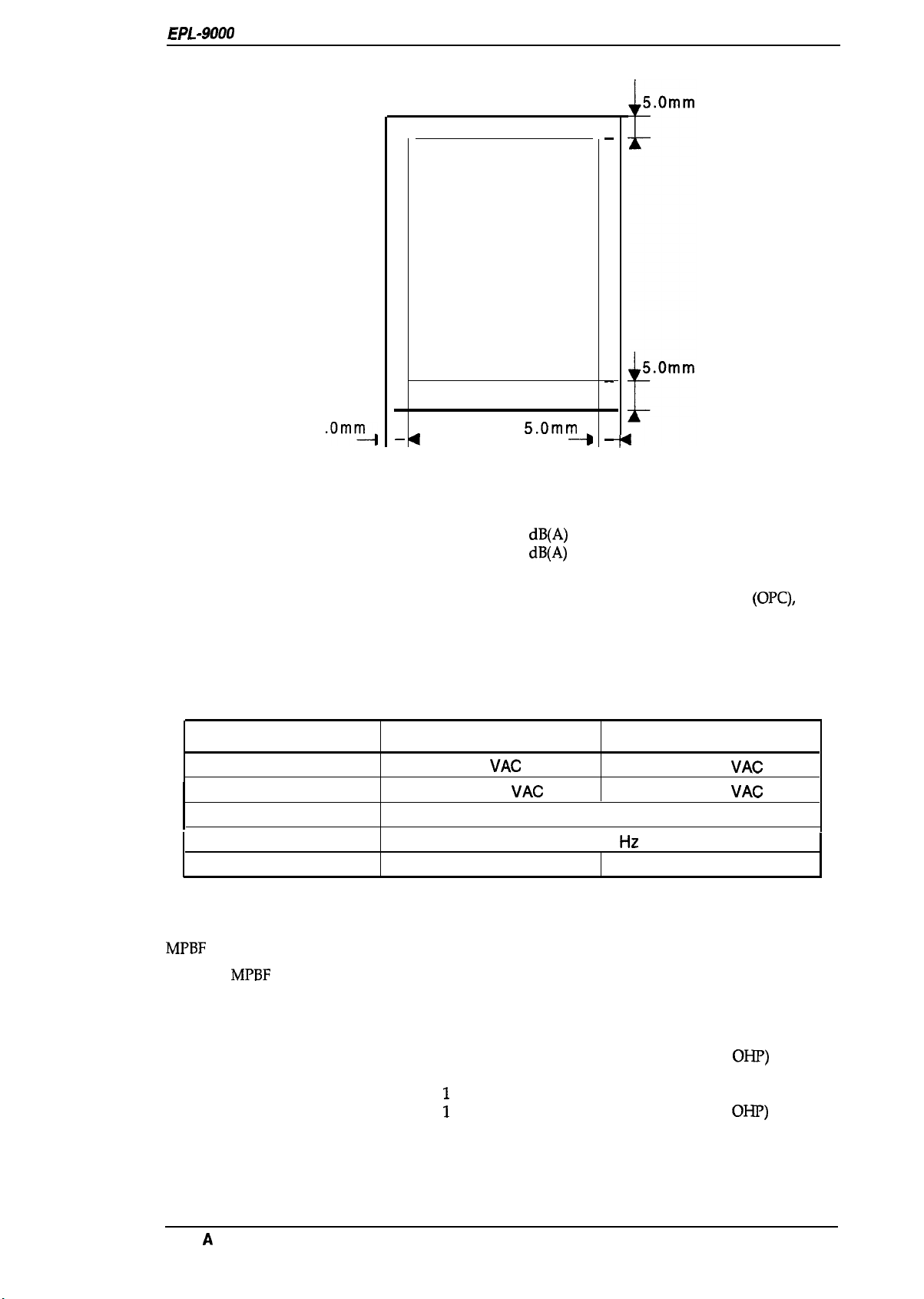
Printable area (standard paper):
5
.Omm~
—
Figure 1-2. Printable Area
Note:
Noise:
Ozone density:
Toxicity:
The actual printable area depends on the printer mode.
See Figure 1-2.
—
Printable Area
—
I
Less than 35
Less than 48
5.Omm
dB(A)
dB(A)
—
(standby)
(operating)
0.05 ppm (typical)
No toxicity exists in organic photo conductor
or plastic materials
(OPC),
toner,
1.2.2 Electrical Specifications
Table 1-5. Electrical Specifications
Description
Rated voltage
Input voltage range
Rated frequency range
Input frequency range
Power consumption
100 V Version 200 V Version
115
VAC
104-127
Less than 500 W
1.2.3 Reliability Specifications
MPBF
(Mean Prints Between Failures): Over 12,000 sheets
MPBF
Note:
Jam rate:
Multiple paper feeds:
Paper curl height:
MTTR (Mean Time To Repair):
Durability:
indicates average number of pages printed before occurrence of problem requiring
replacement or service.
1 out of 3,000 sheets or less (Standard paper)
1 out of 2,000 sheets or less (Normal paper)
1 out of 25 sheets or less (Label, Envelope,
1 out of 800 sheets or less (Standard paper)
1
out of 500 sheets or less (Normal paper)
1
out of 25 sheets or less (Label, Envelope,
30 mm (1.2 inches) or less
30 minutes or less
5 years or 300,0000 sheets
VAC
50-60 Hz
47-63
Hz
220-240
198-264
VAC
VAC
Less than 600 W
OHP)
OHP)
Rev.
A
1-5
Page 17
General
Description
EPL-XXUI
Service Manual
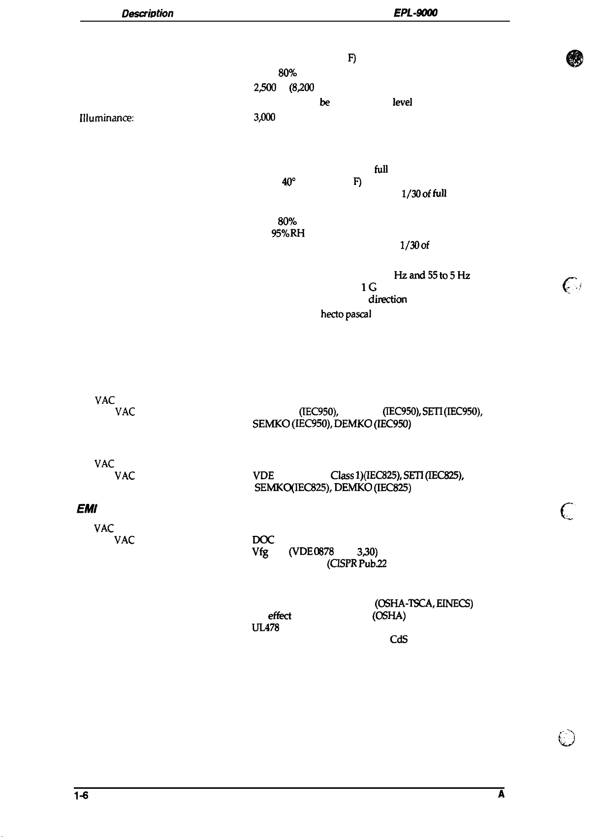
1.2.4 Environmental Conditions for Operation (Including Imaging Cartridge)
Temperature:
Humidity:
Altitude:
Levelness:
Illuminance:
10 to 32° C (50 to 90°
20 to
80’Yo
RH
2~
m
(8ZO0
feet) or lower
Printer should be installed on a
3@Kl
I
UX
or less (Must not be exposed to direct sunlight.)
F)
level
plane.
1.2.5 Environmental Conditions for Storage and Transportation
Temperature:
Humidity:
Drop test:
Vibration:
Resistance to atmospheric pressure:
Storage term:
O to 35° C (32 to 95° F) over
–20 to
4(Y
C (-4 to 104° F) under extreme conditions
(Extremes are allowable for up to
Temperature variation must be 10° C (18° F)/hour or less
20 to
8070
RH
over full storage term
5 to
%?. RH
(Extremes are allowable for up to
Height 52 cm
Vibration frequency
Acceleration
Acceleration direction 3
More than
12 months (following date of manufacture)
under extreme conditions
740
hecto pascal
full
storage term
5 to55
IG
diwction
l/300f full
l/300f
full storage term)
Hzand55
storage term)
to5Hz
-
c
:...
,
,7
1.2.6
Applicable Standards
Safety
120
220/240
Standards
VAC
model:
VAC
model:
None
EN 60950
SEMKO (IEC950), DEMKO (IEC950)
Safety Regulations (Laser radiation)
120
VAC
220/240
model:
VAC
model: VDE
None
SEMKO(IEC825), DEMKO (IEC825)
EMI
120
VAC
220/240
model:
VAC
model:
None
DOC
Vfg
EN55022 class B
Others
Toner:
OPC:
Ozone:
Materials:
No effect on human health
No effixt on human health
UL478
SWISS Environmental Law (No
(IEC950),
0837 (Laser
Class B
243
(VDE (X378
(5th edition)
NEMKO
Class 1)(IEC825), SETl (IEC825),
Part
(CISPR Pub.22
(IEC950), SETI (IEC950),
3s0)
class B)
(OSHA-T!XA, EINECS)
(OSHA)
CdS
must be contained)
“,.
c
..-
1-6
Rev.
A
. . .-
k:.
,.
h’.)
Page 18

EPL-9000
Service Manual
1.2.7 Specification for Consumable (Imaging Cartridge)
General Description
Life:
Note:
Environmental
Temperature:
Humidity:
Drop test:
Vibration:
Resistance to atmospheric pressure:
Storage term:
1.2.8
Dimensions (Width x Depth x Height):
Printer:
Weight:
In continuous printing mode with
ratio). The life varies, depending on the printing mode (continuous or intermittent)
and/or the image ratio.
CondRions
for Storage and Transportation
Physical Specifications
6,500 pages
O to 35° C (32 to 95° F) over full storage term
–20 to 40° C (-4 to 104° F) under extreme conditions
(Extremes are allowable for up to 1/30 of full storage term)
Temperature variations must be 10° C (18° F)/hour or less.
20 to
5 to
(Extremes are allowable for up to 1/30 of full storage term)
Height 76 cm (30.4 inches)
Same as printer
More than 740
24 months (following date of manufacture)
437 x 473 x 270 mm (17.2 x 18.6x 10.6 inches)
Approx. 17 Kg (37.5 lb.) (consumable, excluding all options)
A4/letter
80Y0
95~0
RH under extreme conditions
paper at a
RH over full storage term
hecto pascal
5’XO
image ratio (black/white
Rev.
A
1-7
Page 19
General Description
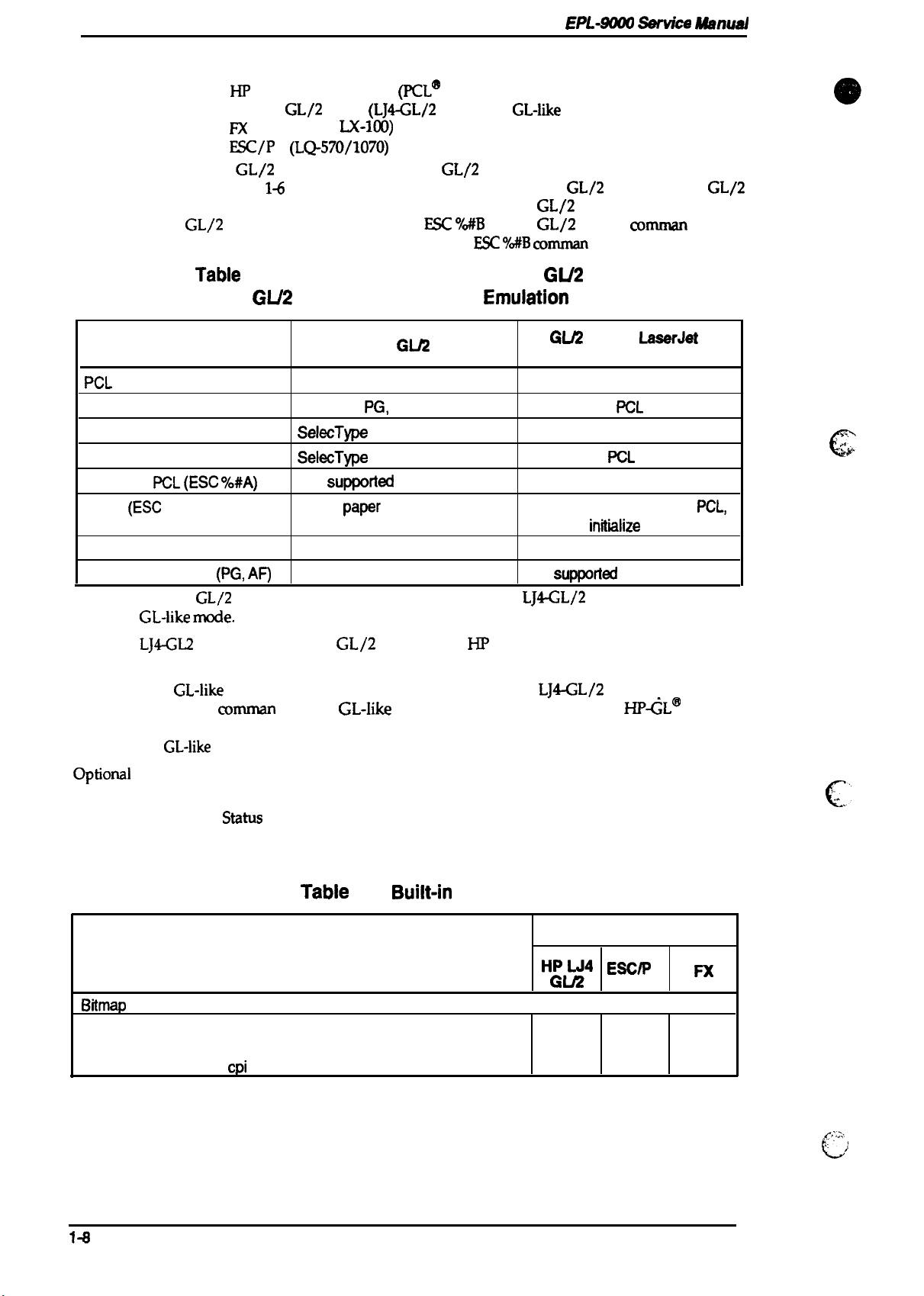
1.2.9 Software Specifications
HP
Built-in modes:
Note:
The EPSON
emulation. Table 14 shows the differences
mode in the HP LaserJet 4 emulation. While in EPSON
enter
operator’s application software cannot send the
GL/2
Tabie
LaserJet 4 emulation
EPSON
M
ESC/P
GL/2
mode without sending the
GL/2
mode
@$70/1170,
2
(LQ-570/1070)
mode is similar to the
LX-NM)
1-6. Differences between EPSON GU2 and
GU2 in the HP LaserJet 4
EPSON
(PCL@
5e)
(LJ4-GL/2
mode
mode and
emulation mode
GL/2
between EPSON
ESC ‘3WB
GL/2
Mode
EPL-9tlXXl ti”ce Wnual
GL-like
mode included in the HP LaserJet 4
(Enter
ESC ‘MB comrnan
mode)
GL/2
mode and the
GL/2
mode, the operator can
GL/2
mode)
cornman
d, then use this mode.
GL/2
d. If the
Emuiation
GlJ2
for HP
Emulation Mode
LaserJat
4
PCL
mode
Paper eject
Auto eject
Reduced printing
Switch to
Reset
PJL, EJL, and ES
Advance Full Page
Notes:
Optioml
Auxiliary software: Hex dump
Built-in fonts: See Table 1-7
PCL (ESC OA#A)
(ESC
E)
(PG, AF)
EPSON
GL-like rncde.
LJ4-GL2
print with software that supports the HP 7600 series plotter.
The
additional
(HP 7475A, etc.) co
the
modes: EPSONScript Level 2 (PostScript Level 2 emulation) mode
GL/2
mode has two operational modes. One is
mode emulates the
GL-like
GL-like
mode features all the cornmands of the
comrnan
mode, print cannot be assured.
Status
Font sample
Does not exist
Supports
SelecType
SelecType
Not
Ejects
supported supported
supported
ds. The
remands. If the application software uses unsupported co
sheet
PG,
AF commands
setting
setting
SUflflOrted
papr
and then initialize
GL/2
mode in the HP LaserJet 4 emulation. The user can
GL-like
mode emulates some of the
Exists as the initial mode
Supported in
Not available
Available in
supported
Ejects paper, switches to
and then
Not
SUppIOlted
LJ4-GL/2
LJ4-GL/2
PCL
PCL
PCL,
init”wlize
mode; the other is the
mode, plus a few
HP<L@
plotter
remands for
,.,
,{
‘$+
c
. .
c.’
Resident
BitrnaP
fonts
Line Printer
Prestige
Prestige
S:
Supported, NS: Not Supported
1-8
16.66 cpi (Portrait)
12 cpi
20
cpi
Tabie
Fonts
(Portrait)
(Portrait)
1-7.
Buiit-in
Fonts
Applicable Mode
H&~4
s
NS
NS
E~/p
NS
s
s
2
F)(
NS
s
s
Rev. A
.
. . . . . . .
(/
“..
.
;
Page 20
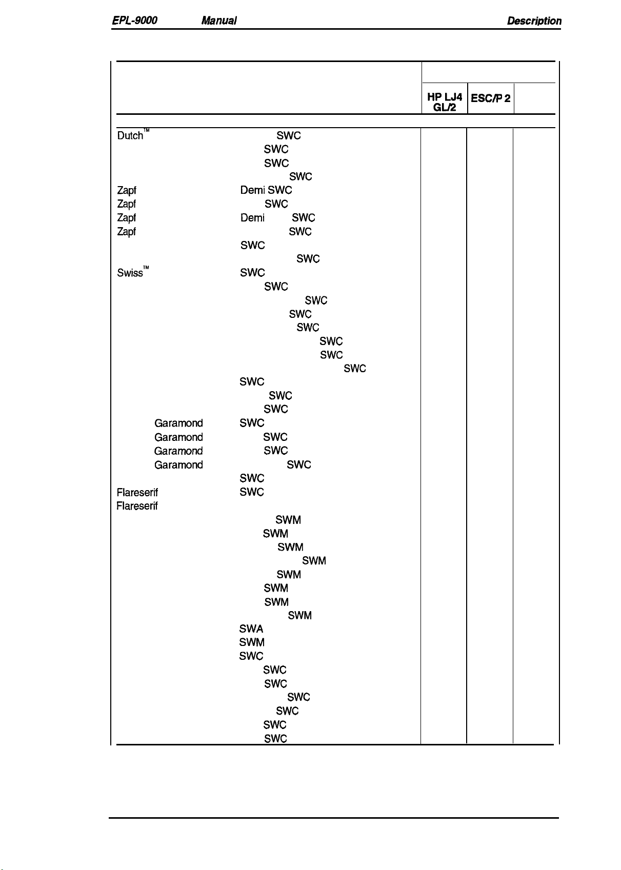
EPL-9000
Scalable fonts
Dutch’”
Dutch 801
Dutch 801
Service
801
Dutch 801
Zapf
Humanist 601
Zapf
Humanist 601
Zapf
Humanist 601
Zapf
Humanist 601
Ribbon 131
Clarendon
Swiss’”
742
Swiss 742
Swiss 742
Swiss 742
Swiss 742
Swiss 742
Swiss 742
Swiss 742
Incised 901
Incised 901
Incised 901
Original
Original
Original
Original
Audrey Two
Flareserif
Flareserif
Swiss 721
Swiss 721
Swiss 721
Swiss
Garamond
Garamond
Garamond
Garamond
821
821
721
Dutch 801
Dutch 801
Dutch 801
Dutch 801
Symbol Set
More WingBats
Courier
Courier
Courier
Courier
Letter Gothic
Letter Gothic
Letter Gothic
Manual
Table 1-7. Built-in Fonts (Continued)
Resident Fonts
Roman
Bold
Italic
Bold Italic
Demi SWC
Bold
Demi
Bold Italic
Swc
Condensed
Swc
Bold
Medium Italic
Bold Italic
Condensed
Bold Condensed
Condensed Italic
Bold Italic Condensed
Swc
Black
Italic
Swc
Bold
Italic
Bold Italic
Swc
Swc
Extra Bold
Roman
Bold
Oblique
Bold Oblique
Roman
Bold
Italic
Bold Italic
SWA
SWM
Swc
Bold
Italic
Bold italic
Roman
Bold
Italic
SWC
SWC
SWC
SWC
Italic
SWC
SWC
SWC
SWC
SWC
SWM
SWM
SWM
SWM
SWM
SWM
SWC
SWC
SWC
SWC
SWC
SWC
SWC
SWC
SWC
SWC
SWC
SWC
SWC
SWC
SWC
SWC
SWM
SWM
SWC
General
Applicable Mode
H:&JQ
s
s
s
s
s
s
s
s
s
s
s
s
s
s
s
s
s
s s
s
s
s
s
s s
s
s
s
s
s
s
s
s
s
s
s
s
s
s
s
ESC~ 2
NS NS
NS NS
NS NS
NS
NS NS
NS NS
NS NS
NS NS
NS
NS NS
NS
NS NS
NS
NS NS
NS
NS NS
NS NS
NS
NS NS
NS
NS
NS NS
NS
NS NS
NS
NS
NS
NS NS
s
NS
NS NS
s
NS
NS
NS
NS
s s s
s s s
s
s
s s s
s
s s s
NS
NS
s
Description
FX
NS
NS
NS
NS
NS
NS
NS
NS
NS
NS
NS
NS
NS
NS
NS
NS
NS
NS
NS
NS
NS
NS
NS
s
S: Supported, NS: Not Supported
Rev. A
1-9
Page 21
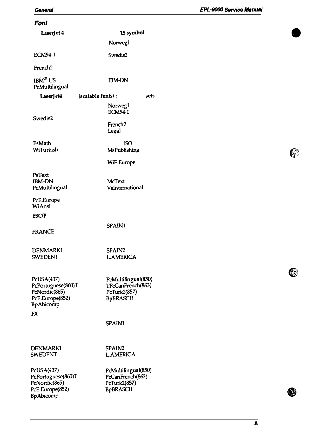
Genersl
F6nt
Symbol Sets
HP
LaserJet4
Description
Mode (bitmap fonts):
15symbol
EPL#UM Ser&e Msnwd
sets
Roman-8
Roman Extension
ECM94-1
ANSI ASCII
Norwegl
Italian
sweclis2
UK
French2 German
Legal
IBti-US
Spanish
IBM-DN
PcMultilingual
HP
LaserJet4
Roman-8
Italian
Sweclis2
UK
German
8859-2 1S0
PsMath
WiTurkish
VeMath
Math-8
Mode (scxdablefonts): 34
Norwegl
ECM941
ANSI ASCII
French2
Legal
Spanish
8859-9
M#ublishing
DeskTop
WiE.Europe
symbol
Iso
PcTk437 windows
PsText
IBM-DN
Pchdultilingual
VeUS
PcE-Europe
WiAnsi
IBM-US
McText
VeInternational
PiFont
symbol
Wingdings
seb
Q
‘:’.7
. .
. .
.
ESCIP
2 Mode:
USA
FR4NCE
GERMANY
UK
DENMARK1
SWEDENT
ITALY
15 International characters and 9 code
SPAIN1
JAPAN
NORWAY
DENMARK2
SPAIN2
L.AMERICA
KOREAR
LEGAL
PcUSA(437)
PcPortuguese(860)T
PcNordic(865)
PcE.Europe(852)
PcMu1tilingual(850)
TPcCanFrench(863)
PcTurk2(857)
BpBRASCII
BpAbicomp
FX
Mode: 13 International characters and 9 code tables
USA
FRANCE
GERMANY
SPAIN1
JAPAN
NORWAY
UK DENMARK2
DENMARK1
SWEDENT
SPAIN2
L.AMEIUCA
ITALY
tables
PcUSA(437)
PcPortuguese(860)T
PcNordic(865)
PcE.Europe(852)
BpAbicomp
1-1o
PcMultilingual(850)
P&anFrench(863)
PcTurk2(857)
BpBRASCII
Rev.
A
Page 22
EPL-9000
Service
Manual
General Description
1.3 INTERFACE SPECIFICATIONS
The
EPL-9000
■ Parallel interface
■
■
Optional LocalTalk interface
■
Optional Type B interface
1.3.1 Parallel Interface
The parallel interface has two modes as follows:
9
Compatibility mode (same as parallel interface of EPSON’s current page printer)
■ Reverse mode
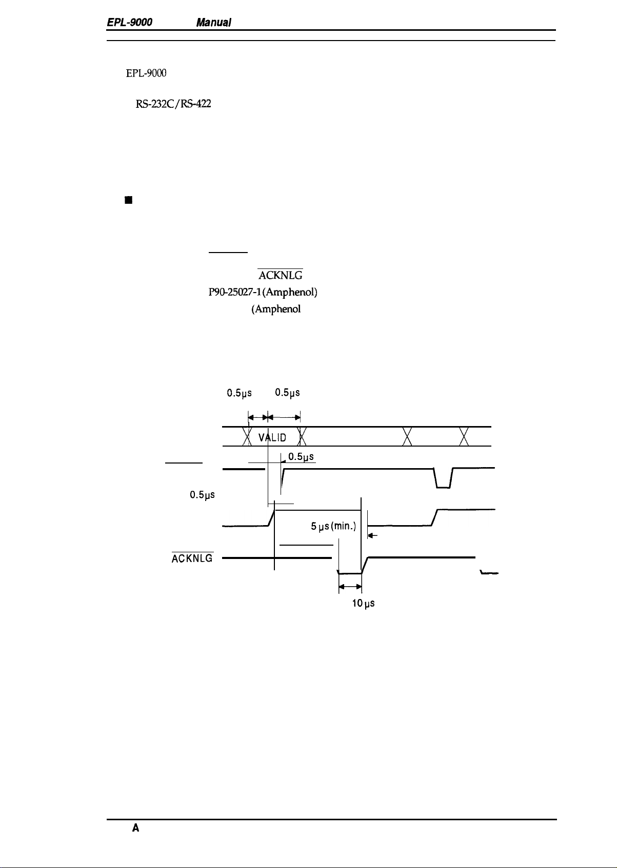
1.3.1.1 Compatibility Mode of Parallel Interface
is equipped with the following external interfaces:
RS-232C/RS-422
interface
System:
Handshaking:
Connector type:
Applicable plug:
Transfer speed:
Signal timing:
Signal description:
DATA 1-8
STROBE
0.5ps
BUSY
ACKNLG
STROBE synchronization, 8-bit parallel data transfer
BUSY and
P90-25027-1 (Amphenol)
57-30360
ACKNLG
(Arnphenol
or equivalent)
signals
receptacle
Approximately 400,000 bytes/second (max.)
See Figure 1-3.
See Table 1-8.
I
VALID
o.5~s
I I
~
\ -
/
0.5 or
(minimum)
0.5ps
(minimum)
0s
5pS (min.)
●
\
VALID
+
I
o.5@
(minimum) (minimum)
(maximum)
I
El
1 or
IOps
(typical)
\
Rev.
Figure 1-3. Compatibility Mode
A
Signal Timing
1-11
Page 23
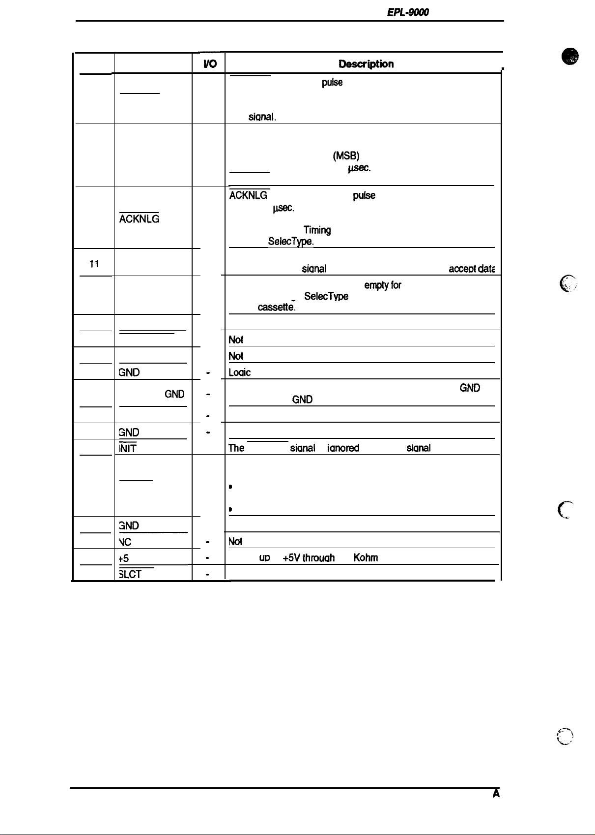
General Description
Table 1-8. Parallel Interface Pin Assignments
EPL-$WO
Service Manual
Pin No.
1
2-9
10
11
12
13
14
1516NC
17
18
19-30
31
32
33
34
35
36
Signal Name
STROBE
DATA 1-8
ACKNLG
BUSY
PE
SLCT
AUTO-FEED
GND
CHASSIS
GND
NC
GND
iii?
ERROR
F5
3LCT
IN
ilo
IN
IN
OUT
OUT
OUT
OUT
IN
.
.
.
.
IN
OUT
.
.
Descri*n
STROBE is a strobe
computer. The pulse width
Normally it is
this
sicmal.
HIGH, and data is latched at the trailing edge of
pufse
used to read data from the host
.
must be more than
0.5&c.
I
.
DATA 1 to 8 are parallel data bits. When the signal is HIGH,
the data bit is 1, and when it is LOW, the data bit is O.
The most significant bit
must be maintained for 0.5
(MSB)
is DATA8. The signal state
p.aec.
on either side of the
STROBE signal active edge.
ACKNLG
of 1 or
reception is completed,
accept new data.
through
The BUSY
state. When the
The PE
selected through
paper
is an
10
acknowledge
psec.
This signal goes LOW
pufse
with an approximate width
when the data
which indicates that the printer can
l“iming
with the
BUSY signal is specified
SelecType.
signal informs the host computer of the printer
sianal
is HIGH. the minter cannot
signal indicates paper
SelecType
cassett~
Paper empty is indicated by HIGH.
ernptyfor
the standard tray
or command, or for the optional
acceot dat~
-
Use in reverse mode.
Not
used.
Not
used.
Loaic
around level.
connected to the printer chassis. The printer chassis
and the signal
GND
are connected to each other.
GND
Not connected.
Ground level for the twisted pair return signal.
me
STROBE
sianal
is
ianored
when this
sianal
is LOW.
This level goes LOW when the printer is:
●
out of paper
D
in paper jam state
●
in error state
o
off line
Same as for tins19 to 30.
Not
used.
Pulled
Use
UD
to
+5V thmuah
the reverse mode.
1.0
Kohm
resistance.
c’
1-12
Rev.
A
Page 24
EPL-9000
Service Manual
General Description
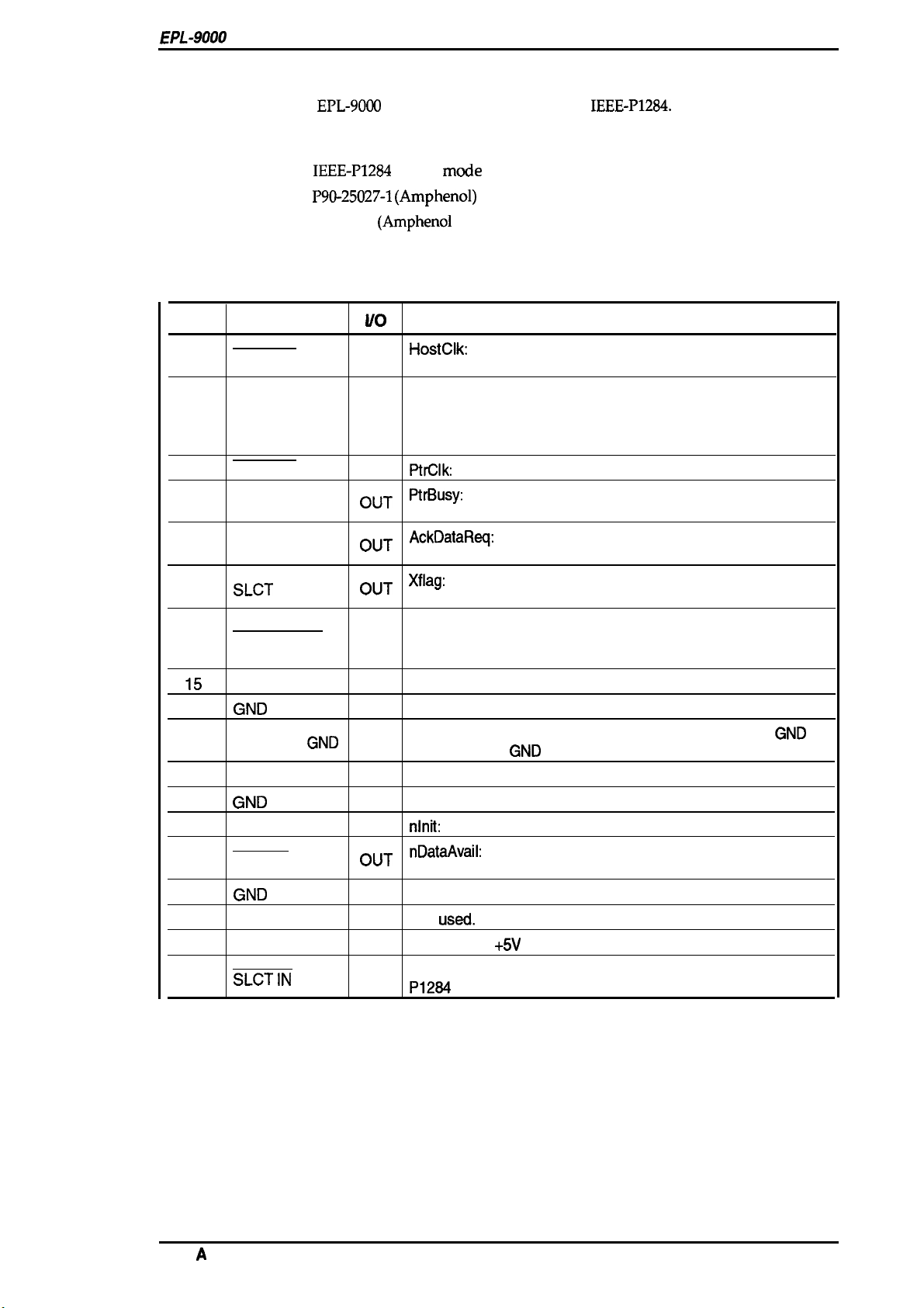
1.3.1.2
The reverse mode for
Reverse Mode
EPL-9000
supports the nibble mode of
IEEE-P1284.
This printer can run in
reverse mode, in which the printer can inform the computer of its status by EJL and PJL
commands.
System:
Connector type:
Applicable plug:
Signal description:
IEEE-P1284
P90-25027-1 (Amphenol)
57-30360
See Table 1-9.
nibble
(Amphenol
mmle
or equivalent)
receptacle
Table 1-9. Parallel Interface Pin Assignments
Pin No.
1
2-9
10
11
12
13
14
15
16
17
18
19-30
31
32
33
34
35
36
Signal Name
STROBE
DATA
1-8
ACKNLG
BUSY
PE
SLCT
AUTO-FEED
NC
GND
CHASSIS
NC
GND
GND
INIT
ERROR
GND
NC
+5
SLCT IN
I/o
IN
IN
OUT
OUT
OUT
OUT
IN
-
.
IN
OUT
.
IN
HostClk:
request values from the host computer during negotiation.
The signals are data
negotiation.
This signal is a strobe pulse used to read extension
This printer supports following values:
0000 0100: Request Device ID (by nibble mode sending)
0000 0000: Request nibble mode
PtrClk:
Printer data sending clock.
PtrBusy:
Printer sending data bits 3 and 7 during data transfer
to host computer.
AckDataReq:
Printer sending data bits 2 and 6 during data
transfer to host computer.
Xflag:
Printer sending data bits 2 and 6 during data transfer to
host computer.
HostBusy: This signal informs the printer of the host computer
state. When the signal is HIGH, the host computer cannot
accept data.
Not used.
Logic ground level.
Connected to the printer chassis. The printer chassis
and the signal
Not connected.
GND
Ground level for the twisted pair return signal.
nlnit:
High level fixed
nDataAvail:
Printer sending data bits O and 4 during data
transfer to host computer.
Same as for pins19 to 30.
Not
USf2d.
Pulled up to
+5V
through 1.0 Kohm resistance.
1284Active: If this signal is set to HIGH, this printer active
P1264
(reverse mode).
Description
bits of extension request values during
GND
are connected to each other.
Rev.
A
1-13
Page 25
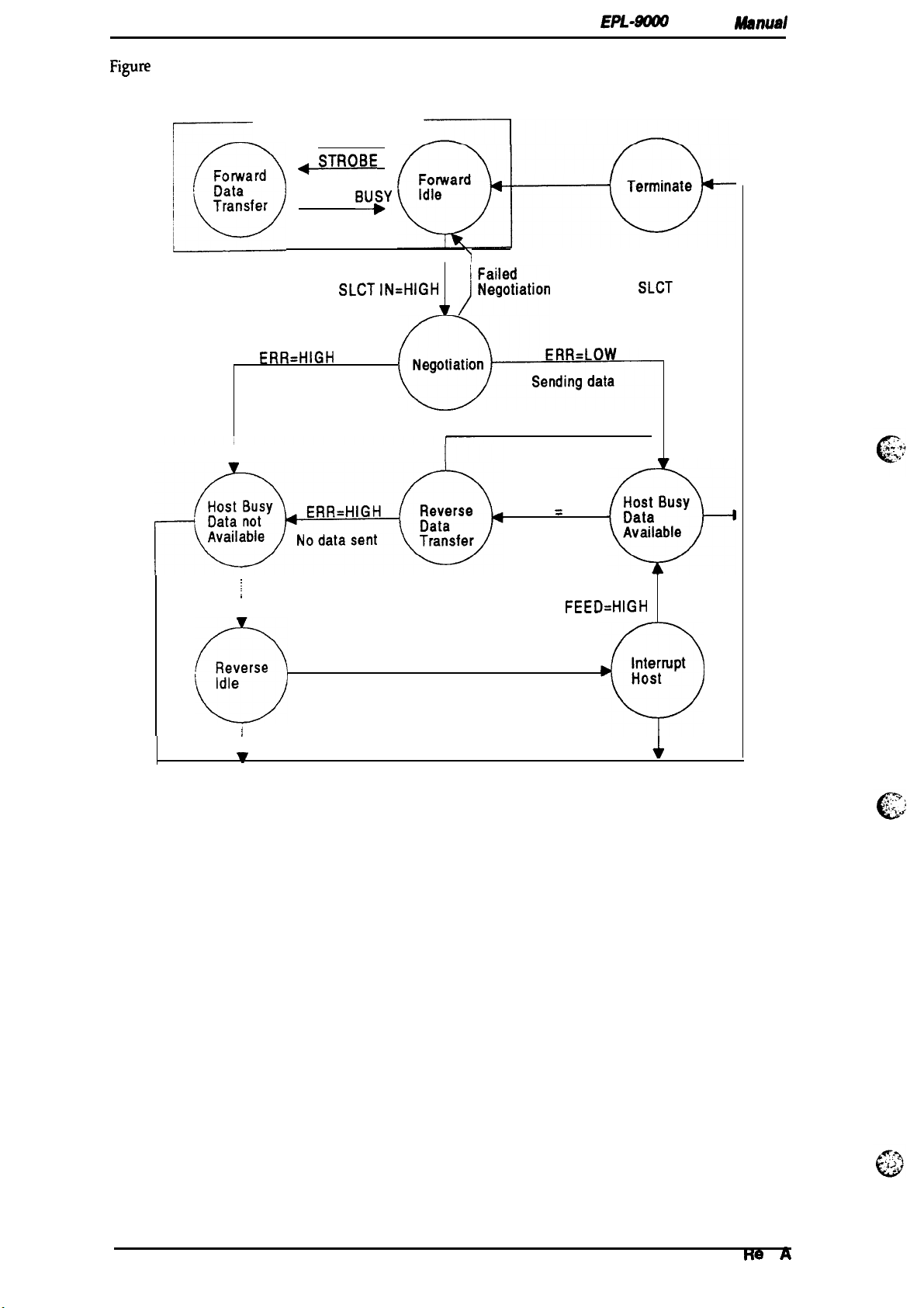
General Description
Figure
1-4 shows the parallel interface state switch diagram.
Compatibility Mode
EPL-XWl Service
Rkwwal
r
,0
Forward
Data
Transfer
ERR=HIGH
No data sent
I
~
AUTO
~
FE ED= LOW
.,,,,,,
ACK and
SLCT IN=HIGH
BUSY
)
SLCT
IN= LOW
ERR= LOW
Sending data
AUTO
=
FFFD LOW
Request to
●
send data
AUTO
FEED=HIGH
ERR= LOW
I
Figure 1-4. Parallel Interface State Switch Diagram
Page 26
EPL-9000
Service Manual
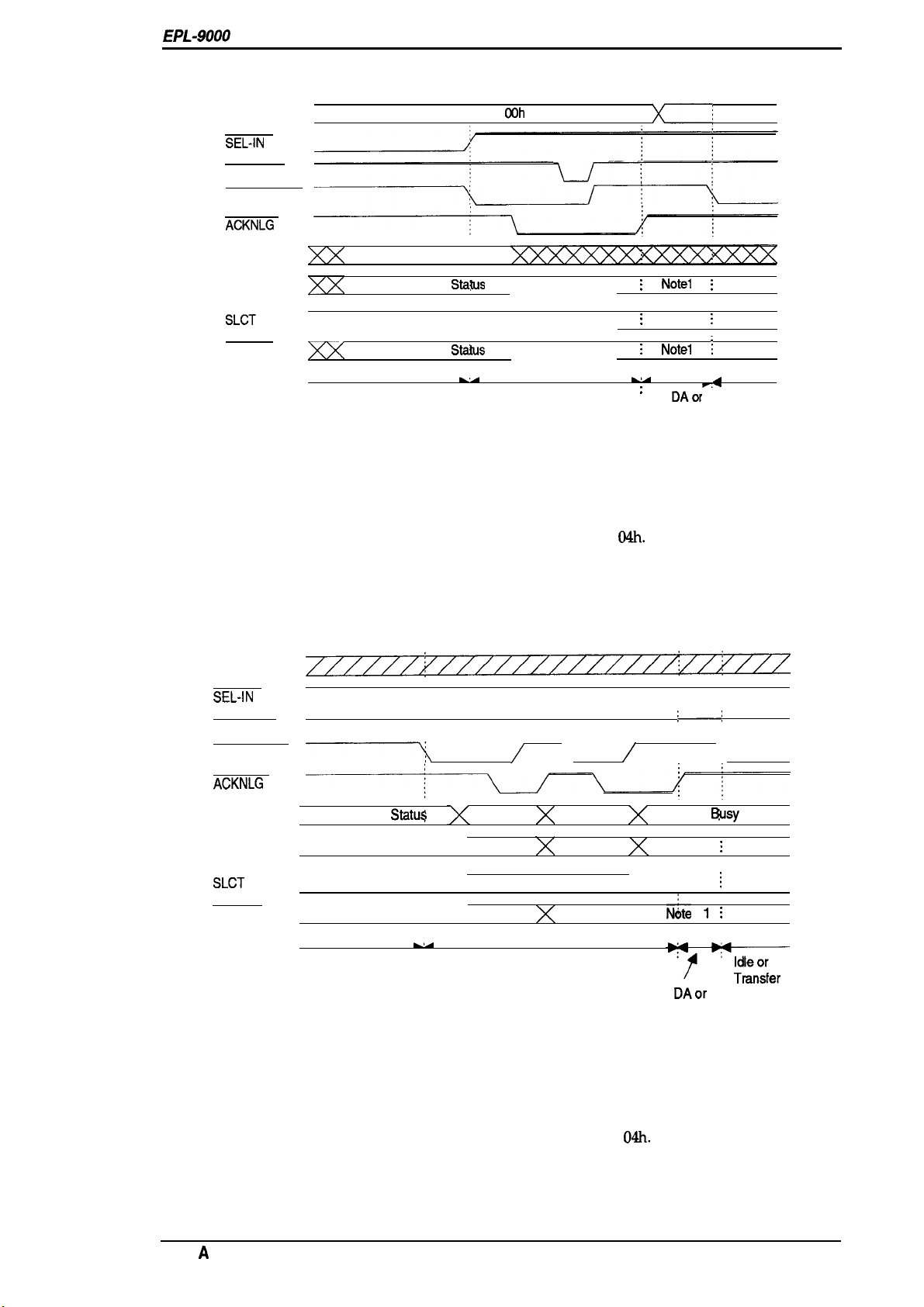
Figure 1-5 shows the negotiation timing chart.
DATA
SEL-IN
STROBE
AUTO-FEED
ACKNLG
COh
or 04 h
General Description
x-
BUSY
PE
SLCT
ERROR
~
Peripheral Busy Status
Current Peripheral
Current Peripheral
Compatibility
Wus
Staius
LA
/
/
Negotiation
\
\
\
!
;
Note 2
;
L,A
:
HB DAor
Figure 1-5. Negotiation Timing Chart
Note
1: The signal is set to HIGH when not sending data.
The signal is set to LOW when sending data.
Note 2: The signal is set to HIGH, if extension request value was
Note3: HB DA: Host Busy Data Available
HB DNA: Host Busy Data Not Available
Figure 1-6 shows the data transfer timing chart.
DATA
SEL-IN
STROBE
AUTO-FEED
/
04h.
/
Notel ;
Notel
HB DNA
(Note 3)
:—;
;
;
A
-
:
Idle or
Transfer
ACKNLG
X
BUSY
PE
SLCT
ERROR
Peripheral Busy Statu$
HB DA
k,-
Bit 3
Bit 2
Bit 1
Bit O
Bit 7
Bit 6
Bit 5
Bit 4
Negotiation
Peripheral
Figure 1-6. Data Transfer Timing Chart
Note 1: The signal is set to HIGH when not sending data.
The signal is set to LOW when sending data.
Note 2: The signal is set to HIGH if the extension request value is
Note 3: HB DA: Host Busy Data Available
HB DNA: Host Busy Data Not Available
04h.
N&e 1
N&e 2
N;te 1 ;
HB
DAor
HB
DNA
(Note 3)
Msy
;
;
Status
Rev.
A
1-15
Page 27
Genere!
Description
EPL-~
Service
Menual
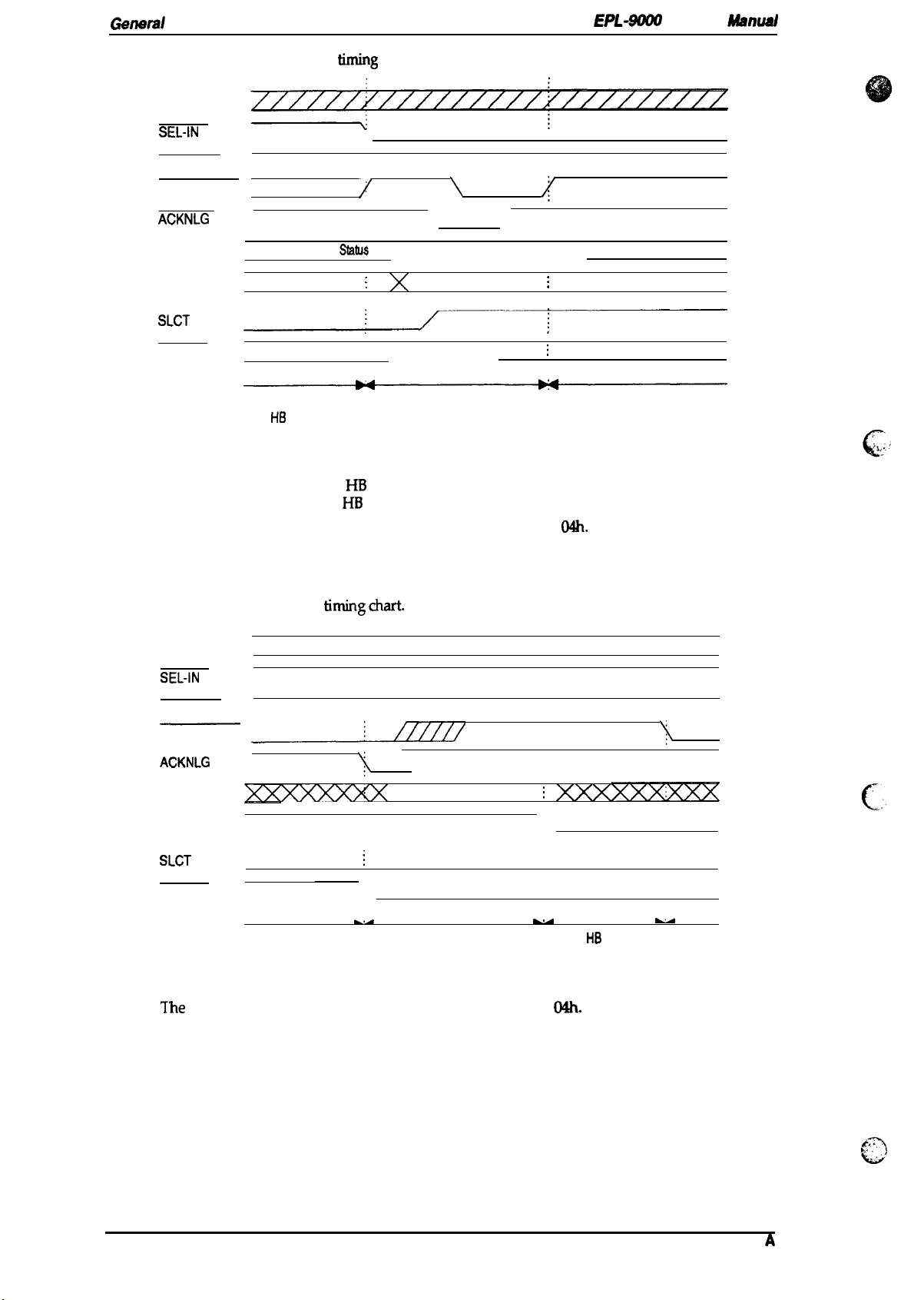
Figure 1-7 shows the te
DATA
SEL-IN
STROBE
AUTO-FEED
ACKNLG
BUSY
PE
SLCT
ERROR
rrnination
Note 3
Peripheral Busy
HB DNA, Idle,
or HB DA
Note 1
Note 2
Note 1
Figure 1-7. Termination Timing
fining chart.
/
!3atu.$
;
~
\
\ /
Termination
$
\ Peripheral Busy Status
;
current Peripheral status
;
Current
chart
Note 1: The signal is HIGH when HB DNA.
The signal is LOW when
Note 2: The signal is set to HIGH if the extension request value is
HB
DA.
03h.
Note3: Idle= LOW
Peripheral Status
Compatibility
Figure 1-8 shows the interrupt
DATA
SEL-IN
STROBE
AUTO-FEED
—.
ACKNLG
BUSY
PE
SLCT
ERROR
Reverse Idle
tirningchart.
XXXXXX
Note 1
Figure 1-8. Interrupt Timing Chart
Note 1:
The
signal is set to HIGH, if extension request value was
$
Peripheral Busy status
i
u
-
:
Interrupt
~
;
-
HB
DA
u
:
Transfer
c.
.
O&
1-16
Rev.
A
Page 28
EPL-9000
Service Manual
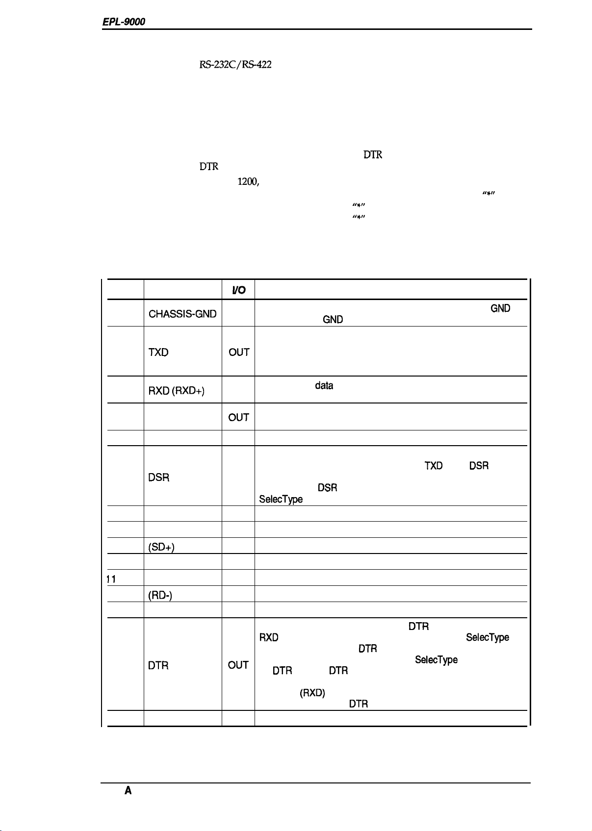
1.3.2 Serial Interface
Type: RS-232C/R%122
Transfer system:
Synchronization:
Full duplex
Asynchronous start-stop system
Start-bit:
Stop-bit: 1 or 2 bits
Data length: 7 or 8 bits
Parity:
Protocol:
Transfer speed:
X-ON/X-OFF (can be combined with
DTR
control (can be combined with X-ON/X-OFF)
300,600,
12tXl,
2400,4800,9600,19200,38400, or 57600 bps
Error: Overrun error:
Parity error:
Framing error:
Breaking Character: Ignored
Signal description:
See Table 1-10.
Table 1-10. Serial Interface Pin Assignments
General Description
1 bit
Odd, even, or none
DTR
control)
Processed as missing data and replaced by
Replaced by
Replaced by
“’”
““”
““”
Pin No.
1
2
3
4 RTS
5
6
7
8
9
10
11
to 17
18 (RD-)
19
20
21-25
Signal Name
CHASSIS-GND
TXD
RXD (RXD+)
Uo
-
~uT
IN
OUT Transmission request signal output from the printer. It is
CTS
DSR
SIGNAL-GND
DCD
(SD+)
IN
IN
-
IN
OUT
(SD-) OUT
NC
IN
NC
DTR
OUT
NC
Description
Connected to the printer chassis. The printer chassis
and the signal
GND
are connected to each other.
GND
Serial ASCII data output by the printer. It maintains “MARK’
state
(LOW level) between transmitted character codes.
Logic O is at HIGH level (“SPACE”) and logic 1 is at LOW level
(“MARK”).
Serial ASCII
data
input to the printer. It maintains “MARK”
state (LOW level) between received character codes.
always at HIGH level during power ON.
Always ignored.
Signal input to the printer.
The printer can transmit data through
TXD
while
DSR
is at
HIGH level. X-ON/X-OFF, however, can be transmitted
regardless of
SelecType
DSR
state. It can always be ignored by setting
(factory setting).
Ground.
Always ignored.
See Note 4.
See Note
Not connected.
See Note 4.
Not connected.
Signal output by printer. When the
RXD
settings do not specify
while the printer power is on. When
for
DTR
4.
DTR
signals HIGH, the
signal can be received by the printer. The
DTR
control, the signal level is HIGH
SelecType
control,
DTR
goes LOW in case of any error
SelecType
setting is used
conditions.
The data
128 characters after
(RXD)
from host computer must be stopped within
DTR
goes LOW.
Not connected.
Rev.
A
1-17
Page 29

General Description
Epl.-m Serwe‘ Manual
Note 1: ( )
Note 2:
Note3: Although the
Note4: SD+, SD-:
indicates an
‘US”,
“DSR”,
for
RS-422
mode if selected through
Serial ASCII data output from the printer.
HIGH level; when SD+ voltage is higher than SD-voltage.
LOW level; when SD+ voltage is less than SD-voltage.
Logic O is “SPACE” and logic 1 is “MARK” state must be maintained between
transmitted character codes.
RD+, RD-:
Serial ASCII data input from the computer.
HIGH level; when
LOW level; when
Logic O is “SPACE” and logic 1 is “MARK” state must be maintained between
transmitted character codes.
Handshaking
When the
cede or sets the
Once
or sets the
vacant area
DTR signal leveI
the vacant area for data in
DTR flag
to
RS-422
signal, which is
and
“DTR”
states can be selected through
signaIs Rn, ~, DSR, DTR,
RD+
voltage is higher than
RD+
voltage is less than
for data in the input buffer drops to 256 bytes, the printer outputs an
to LOW, indicating that the printer cannot receive more data.
the
buffer recovers to
HIGH,
indicating that the
SelecType.
SelecType.
and DCDare
SelecType.
RD-
RD-
voltage.
5X2
bytes, the printer outputs an X-ON code
printer is again ready to receive data.
RS-232Clevel,
voltage.
theycanbe used
X~FF
G
.,.,:
~,,.
Protocol
There are two types of protocols, as listed below, and each of them can be designated by
independently.
■
DTR/DSR
SelecType
the printer is ready to receive data, and to LOW when conditions indicate an error or that the
receiving buffer is full.
When the error is cleared and the printer returns to on-line mode, the signal returns to HIGH.
When
TXD
only when
setting for
■ X-ON/X-OFF
SelecType
indicates an error, and the printer warns the host to stop data transmission within 128 characters.
No further X-OFF codes are sent in response to additional data received from the host after the
X-OFF code has been sent once. The
error are cleared.
When the remaining capacity of the receive buffer reaches 256 characters, X-OFF
once. It is sent only once, even if there are multiple errors. The printer goes on line automatically at
power on, and outputs an X-ON code. Transmission of X~N/X-OFP codes can be defined by
SelecType.
protocol
is used to execute the
SelecType
is used to set the
DSR
is at the HIGH level (DSR is always considered HIGH when the
DSR
is OFF). X-ON/X~FF transmission is independent of the
(DC1/DC3) protocol
is used to execute the X-ON/X-OFF protocol. The X-OFF
DTR/DSR
DTR controI
control protocol. The
X43N
DTR
OFF,
(DCl) code is output after
DTR
is always set HIGH. The printer transmits
signal is set to HIGH when
DSR
state.
(DC3)
code is output if status
all
renditions given in the
(DCl)
SelecType
SelecType
is output
“.+,
c“
.
.
/’
1-18
Rev.
,*
J
G
A
Page 30
EPL-9000
Service Manual
1.3.3 Optional LocalTalk Interface
This printer can use the optional LocalTalk interface module.
General Description
Type:
Signal level:
Protocol:
Transfer speed: 230.4 K bps
Signal description:
LocalTalk
Same as RS-422 signal level
X-ON/X-OFF (cannot be combined with
DTR
control (cannot be combined with X-ON/X-OFF)
See Table 1-11.
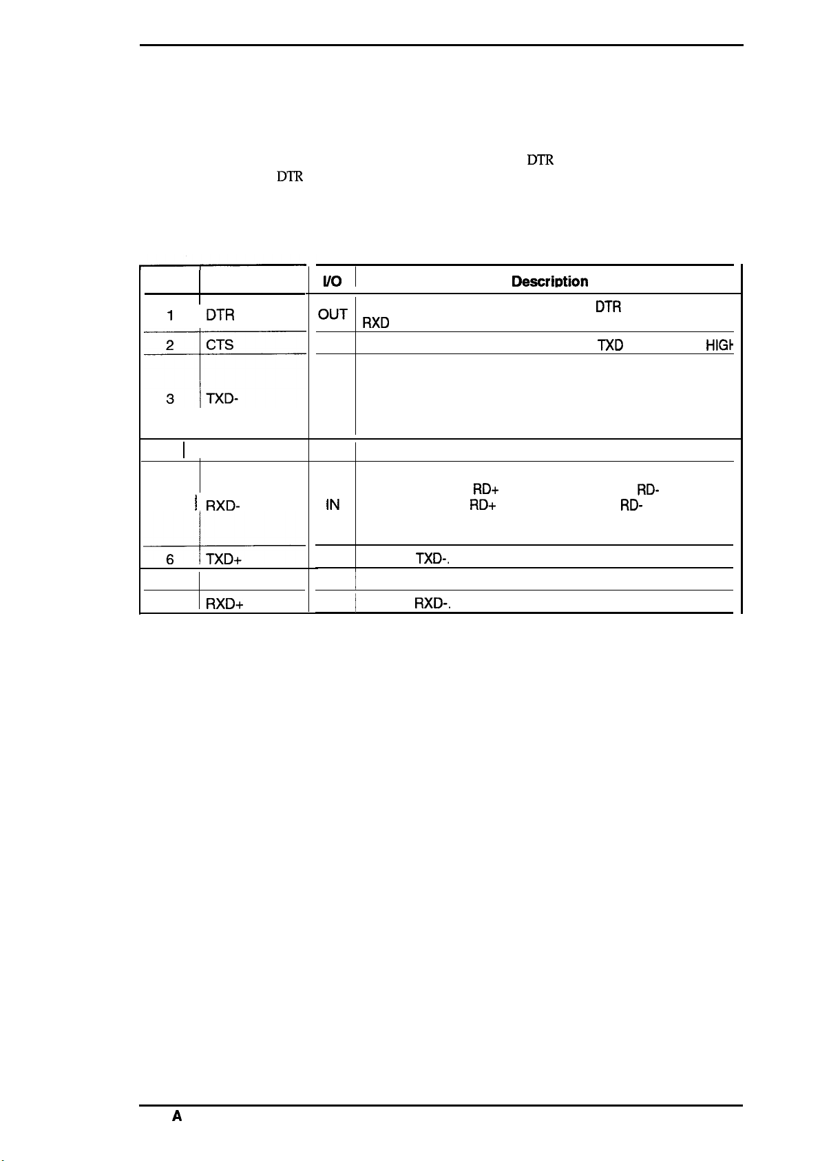
Table 1-11. LocalTalk Interface
Pin No.
1
Signal Name
DTR
I/o
~“T
IN
OUT
I
4 I GND
\
RXD-
5
TL----
NC
7
8
RXD+
IN
OUT
INI Refer to
DTR
control)
Pin Assignments
DescritXion
Signal output by the printer. When the
RXD
signal can be received by the printer.
The printer transmits the data through
Serial ASCII data output from the printer.
HIGH level; when SD+ voltage is higher than SD- voltage.
LOW level; when SD+ voltage is less than SD- voltage.
Logic O is “SPACE” and logic 1 is “MARK” state must be
maintained between transmitted character codes.
Ground.
Serial ASCII data input from computer.
HIGH level; when
LOW level; when
Logic O is “SPACE” and logic 1 is “MARK” state must be
maintained between transmitted character codes.
Refer to
\
Not
TXD-.
connected.
RXD-.
RD+
voltage is higher than
RD+
voltage is less than
DTR
signals HIGH, the
TXD
while CTS is
RD-
voltage.
RD-
voltage.
HIG}
Rev.
A
1-19
Page 31

General Description
EPL-m ~
“
MWluel
1.4 OPERATING INSTRUCTIONS
This section describes the functions performed through the control panel, such as test print,
hexadecimal dump, and
1.4.1 Control Panel
The printer control panel gives you easy control over most common printer operations. The panel
consists of a liquid crystal display
\
SelecType
functions.
(LCD),
indicator
lighk,
and buttons.
~A?600=
o
cmL#n
❑
n
Fmn
Feed ontmw
MamMl
Resel
n
‘w ‘p-q’ ‘:’
ALT Menu
TI_w
Seiea
Item
MPTray
Sue
A
v
‘H’
Enter
‘1
❑
Figure 1-9. Control Panel
Display (LCD)
A 20-character (5
status. A variety of printer parameters can be displayed and set using
Indicator lights
■ On Line
on:
off
Flashing:
■ Form Feed
This LED indicates the data processing condition for each interface channel: S, P, L, and O.
on:
m
Flashing
■ Continue
x 7 dot matrix) by l-row liquid crystal display (LCD) unit that indicates printer
SelecType
Communication with the host is possible.
Communi@tion
This state occurs when the system cannot shift from off line to on line, or vice
versa.
Received data is stored in the printer but has not been printed.
There is no printable data
The printer is processing data.
with the host is not currently possible.
remainin
gin the printer.
mode.
..$$
c’
Flashes when an error is detected or a maintenance procedure is needed. An error message appears
on the display at the same time.
Rev.
1-20
A
e
Page 32

EPL-9000
Buttons
Service Manual
General Description
■ On Line
■ Form Feed
■ Manual
(Form Feed +
■ Continue
■ Reset
(Continue +
■
ALT
~
Menu
■ Tray Select
(Menu+
H
Item
■
MP
Tray Size
(Item+
Alt)
■ ’r
■
~
(~+
Alt)
■ Enter
Alt)
Alt)
Ah)
Switches the printer between on-line and off-line mode. While in
SelecType
mode, this button exits
SelecType
mode.
When the printer is off line and the Form Feed light is lit, pressing
this button prints out data in the printer’s memory.
Enters directly (short cut) to manual feed; this setting is the same as
the manual setting in the PRINTING MENU of
SelecType.
Pressing this button when the Continue light is flashing clears an
error.
Enter to reset operation; LCD displays “RESET”, printing stops, and
the input buffer of current interface is cleared.
If the RESET button is depressed continuously after “RESET” is
displayed, the message displayed on the LCD changes to “RESET
ALL” (about 5 seconds), and the printer enters to WARM BOOT
operation; printer clears all RAM.
Modifies the function of other buttons.
Enters
Changes the menu in
SelecType
mode.
SelecType
mode.
Enters directly (short cut) to the paper tray select setting in CONFIG
MENU of
Enters
Changes the item in
Enters directly (short cut) to the
MENU of
Changes to the next available option of
Changes to the previous available option of
Sets available option of
SelecType.
SelecType
SelecType.
mode.
SelecType mcde.
SelecType.
NIP
TRAY SIZE setting in TRAY
SelecType.
SelecType.
Rev.
A
1-21
Page 33

General Description
1.4.2
SeIecType
The
SelecType
functions, such as printing test pages, selecting a paper size, and changing the printer’s
configuration. Enter
Table 1-12 shows the
Functions
function on the printer control
SelecType
SelecType
mode by pressing the
options.
panel
allows the user to control most of the
Menu
or
Item butkm.
EPi-90tM Smme“
h4iwwal
pMter’s
Menu
(Chan%~g#)MENU
PRINTING
LJ4
[Ps)
ESCP2
Table 1-12.
(chan@ ~~~EM
COPIES
PAGE SIZE
ORIENTATION
MANUAL FEED
RITsch
FONT SRC
FONT NUMBER
PITCH
HEIGHT
SYMSET
FORM
SRC
SYMSET’
DEST
—
Font
Pitch
Condensed
T-Margin
Text
CG
country
Auto CR
Auto LF
Zero Char
Bit
SYMS~
Table
lrns~
SelecType
button)
1 to 999
A4, A3, A5, B4, B5, LT, LGR, HLT, LGL,
GLT, GLG, EXE, F4, MON, C1O, DL, C5,
IB5
PORT, LAND
OFF, ON
OFF, LIGHT, MEDIUM, DARK
RESIDENT, CARTRIDGE, DOWNLOAD
O to (available)
0.44 to 99.99
4.00 to 999.75 PT. (Step 0.25)
Roman-8,
ISO, IBM-US,
PcE.EuroPs, PcTk437, WiAnsi,
WiE.Europe, WiTurkish,
Velnternati,
PsMath, VeMsth,
ASCII,
Norwegl, French2,
5 to 128 LINES
o
o to
—
Courier,
Rornsn-T, sane-l-l, Prestige, Script
10
On, Off
0.40 to
1 to (Available) LINES
PcUSA,
PcCanFrenc, PcNordic,
Pc.E.EuroPs, BPBRASCII,
USA, France, Gerrnsny, UK, Denmark
Sweden,
DenrnarlQ, Spain2,
Legal
ON, OFF
ON, OFF
o,
Dark, Light, BarCode
Functions
Available Options
(Cha
ad by
(M%y
CPI
ECM94-1
VeUS,
Swedis2,
to
3199
3199
Rornsn,
CPI,
12
CPI,
1.50
Inch (step 0.05)
Italic,
($
PcMultilin, PcPortuguss,
Itaty,
Spainl, Japan, Norway,
~or 4
button)
ENTER
(step 0.01)
,8859-2 ISO, 8859-9
IBM-DN, PcMuitiiing,
MsPuMishin,
PiFont, Legal, UK, ANSI
Italian, Spanish, German,
Windows
Orator S,
15
CPI,
LatinArneric, Korea,
button)
DeskTop,
Math-8,
sane
Ser
Prop
PcTurk2,
B@bimnP
PsText,
.;, ,,
62
c
.
.
,.;
o
* With option
1-22
Rev. A
Page 34

EPL-9000
Service Manual
General Description
Table 1-12.
Menu
(Chan~~g{)MENIJ
FX
GL2
JOB
EMULATION
SelecType
(Chang~ $%EM
Font
Pitch
Condensed
T-Margin
Text
CG Table
Country
Auto CR
Auto LF
Zero Char
Bit Image
GLMODE
SCALE OFF, AO, Al , A2, A3
ORIGIN
PEN
END
JOIN
PENO
PEN1
PEN2
PEN3
PEN4
PEN5
PEN6
PAGE PROTECT
RESOLUTION
TIMEOUT
PARALLEL
SERIAL
L/T’
AUX*
Functions (Continued)
Available Options
button)
(Changed by? or $ button)
(Set by ENTER button)
Courier, Roman, Orator S, Saris Ser,
Prestige, Script
10
CPI,
12
CPI,
15
ON, OFF
0.40 to 1.50 Inch (step 0.05)
1 to (Available) LINES
Pc
USA, Italic,
PcCanFrenc,
Pc.E.Europe, BpBRASCll,
USA, France, Germany, UK, Denmark,
Sweden, Italy,
Denmark2, Spain2,
ON, OFF
ON, OFF
o,
(j)
Dark, Light, BarCode
LJ4GL2,
CORNER, CENTER
0, 1,2,3,4,5,6
BUIT, SQUARE, TRIANGULAR, ROUND
MITERED, MITEREDBEVELED,
TRIANGULAR, ROUND, BEVELED,
NONE
0.05 to 5.00 mm (step 0.05)
0.05 to 5.00 mm (step 0.05)
0.05
to
5.00 mm (step 0.05)
0.05 to 5.00 mm (step 0.05)
0.05 to 5.00 mm (step 0.05)
0.05 to 5.00 mm (step 0.05)
0.05 to 5.00 mm (step 0.05)
OFF, A4, A3, LT, LGL
600,300
5 to
300
LJ4, FX, ESCP2, PS*,
PS&FX*, PS&ESCP2*, PS&GL2*
LJ4, FX, ESCP2, PS*,
PS&FX*, PS&ESCP2*, PS&GL2*
LJ4, FX, ESCP2, PS*,
PS&FX*,
LJ4, FX, ESCP2, PS*,
PS&FX*, PS&ESCP2*, PS&GL2*
PcMultilin, PcPortugues,
PcNordic, PcTurk2,
Spainl,
GLIike
PS&ESCP2*, PS&G12*
CPI,
Prop
BpAbicomp
Japan, Norway,
LatinAmeric
GL2, PS&LJ4*,
GL2, PS&LJ4*,
GL2, PS&LJ4*,
GL2,
PS&LJ4*,
Rev. A
1-23
Page 35

General Description
EPL-WOO -Joe Manual
Table 1-12.
Menu
(Chan ~:~)MENIJ
!
TRAY SIZE
CONFIG
PARALLEL SPEED
SERIAL
(Chanx t#%EM
MP TRAY SIZE
STD
SIZE
OPT SIZE*
MP MODE
MP TRAY
STD
TRAY
OPT TRAY*
SIZE IGNORE
AUTO CONT
STANDBY DISABLE, ENABLE
AUTO SENSE
TOP
OFFS=
LEIT’
OFFSET
TONER
TONER LIFE
PAGE COUNT
SelecType
61-D
SERIAL TYPE
WORD LENGTH
BAUD RATE
PARITY
STOP BIT
DTR
XON/XOFF
DSR
SelecType
button)
INIT
Functions (Continued)
Available
(Cha
ad by~or~ button)
(%%y
A4, A3, A5,
GLT, GLG,
ENTER button)
64,65,
EXE,
165
A4, A3, %,
GLT, GLG,
64,65,
EXE,
105
A4, A3, A5,
GLT, GLG,
64,65,
EXE,
165
MANUAL, 1ST, EXT
UNLOCK LOCK
UNLOCK, LOCK
UNLOCK, LOCK
OFF, ON
OFF, ON
ON, PARALLEL, SERIAL, (L/T),
o
to
99
oto150
E-’’’*F,
E’”-
F,
o to 99999999
—
FAST, SLOW
ON, OFF
RS232C,
RS422
8,7
9600,19200,38400,57600, 300,600,
1200,2400,4800
NONE, EVEN, ODD
1,2
ON, OFF
ON, OFF
OFF, ON
Optione
LT, LGR, HLT, LGL,
F4, MON, C1O, DL, C5,
LT, LGR, HLT, LGL
F4, MON, CIO, DL, C5,
LT, LGR, HLT, LGL,
F4, MON, C1O, DL, C5,
E-’
F, E** F, E* F,
(AUX)
“
With option
1-24
Rev.
l.’
,..
@
A
Page 36

EPL-9000
Service Manual
Table 1-12. SelecType Functions (Continued)
General Description
Menu
(Chan
TEST
e&g#)MENU
1!
(Chang~ ~~~EM
STATUS SHEET
button)
LJ4 FONT SAMPLE
ESCP2
FONT SAMPLE —
FX
FONT SAMPLE —
FACT SHEET
RITech
TEST PAGE —
PS
STATUS SHEET* —
PS FONT SAMPLE*
PS
FACT SHEET*
CLEANING PRINT —
CLEANING EXEC
“
With option
1.4.3 Service Mode
This printer has four service modes as follows:
Available Options
(Changed by ~ or $ button)
(Set by ENTER
—
—
—
—
—
—
button)
■
Hexadecimal Dump Mode
■
Language Setting Mode
■
Factory Service Mode
■ EEPROM Format
1.4.3.1
Hexadecimal Dump Mode
The hexadecimal dump mode is a useful tool in trouble shooting data control problems. To enter
hexadecimal dump mode, turn on the printer while holding down the Form Feed button until
“HEX DUMP MODE” is displayed.
1.4.3.2
The
sheet. To enter language setting mode, turn on the printer while holding down the
until “CONFIG LANGUAGE” is displayed. The options are changed by pressing the ? and
buttons and are set by pressing the
ENGLISH,
Language Setting Mode
language setting mode allows the user to specify a language for panel displays and the status
Menu
button
~
Enter
button. Available options areas follows:
FRAN~AIS, DEUTCH,
ITALIANO,
Esptiol,
SVENSKA, DANSK, NEDERL,
SUOMI,
PORTUGUI%
Rev. A
1-25
Page 37

Genaml Descri@ion
1.4.3.3 Factory Service Mode
EM-W(W Sarvrca
“ Manual
The factory service
enter factory service mode, turn on the printer while hoMing down the On Line,
Continue buttons until “PRODUCT MENU” is displayed. The
Table
1-13.
mode
is a useful tool for service people. This mode is not available to users. To
t%ctory
seMce settings am shown m
Table 1-13. Factory Service Mode
Menu
(Chan CMJ&MENU
%
VERSION
PRODUCT
(Changed $%EM
CODE ROM
FONT
ROM
LL ROM
(Local Language ROM)*
PS
ROM
(EPSONScript
Module ROM)*
PCOUNT
PCOUNT
TCOUNT
TCOUNT
JCOUNT
JCOUNT
CLEAR
CLEAR
CLEAR
button)
Available
(Chan
ad by
(Set$y
(Diaplayed veraion)
(Diaplayed veraion)
(Diaplayed veraion)
(Displayed
(Page counter value
(Page
(Note 1)
(Toner left counter clear)
(Jam
(Jam counter clear)
veraion)
counter
munter
ciear)
value
Optione
~or$
ENTER button)
diaplayed)
dieplayed)
Fotm
Feed, and
button)
.
(~
. .
* With option
Note 1:
This counter value is
leftoftoner
weight
(~grarns)
in imaging cartridge.
1.4.3.4 EEPROM Format Mode
EEPROM format operations are required only when the video
EEPROM is replaced and these operations are specified m the accompanying documentation.
Defaults for the
Turn on the printer while holding down the On Line, Continue, and Menu buttons until
“FORMAT=EPL9000” is displayed.
EEPROM
format functions can be written to EEPROM as follows:
mntroller
board
(C135 MAIN)
or
c
. .
1-26
Rev. A
Page 38

EPL-9000
Service Manual
General Description
1.4.4 Display of Messages
This printer displays three types of messages on the LCD: status messages, error messages, and
power on messages.
1.4.4.1 Status Messages
The
LCD panel normally indicates the printer’s status and the software mode.
Table 1-14. Status Messages
1
SELF TEST Internal self test
RESET ALL
RESET Resetting
RESET TO SAVE
WARMING UP Warming up
TONER FULL?
STANDBY
READY Normal condition
FORM FEED
1.4.4.2 Error Messages
If any of the following errors occurs, it will be displayed on the LCD panel. The error must be
cleared immediately using the measures shown in the following table.
Message
Warm boot
SelecType
Press the RESET
Toner counter value is low
Power down
Form feeding
is changed while Form Feed light is on.
mode
status
button to reset.
Table 1-15. Error Messages
Message
PAPER JAM
FEED JAM
PRINTER OPEN
INSERT IMAGING
CRTG
INSERT PAPER TRAY
MANUAL FEED
PAPER OUT
TURN PAPER
PAPER SET
PRINT OVERRUN
MEM OVERFLOW
Status
A paper jam has occurred.
A paper jam has occurred
feed process. press the Continue button.
Cover is open.
No imaging cartridge Insert the imaging cartridge
No paper cassette
Select manual feed.
No paper is left in either the
standard tray or the optional
cassette.
Paper
inserl
direction is bad
The paper in the selected tray is
different from the paper size Continue button.
selection.
Engine speed faster than print
image processing.
Data has filled the buffer.
in the
Open the cover and
jammed paper. Then close the
cover.
Remove the jammed paper. Then
Close the cover.
Insert the paper cassette
Inserl
paper and press On Line
button.
Load paper in paper tray or
optional cassette.
Rotate and insert paper.
Load proper paper and press the
Press the Continue button.
Confirm and press the Continue
button. And add optional SIMM.
Measures
remove the
Rev.
A
1-27
Page 39

General Description
EPL-_ Serv#ce
‘ Manual
Table 1-15. Error Messages
Message
ILLEGAL CART
INSERT CART
REMOVE CART
SERVICE REQ.
Xxxxx
1.4.4.3 Warning
If any of the following warnings occurs, it will be displayed on the LCD panel.
The inserted cartridge is not
Cartridge was removed while Form Feed
light was on or the printer was on line.
Cattridge
light was on or the printer was on line.
Printer problem.
was inserted while Form Feed
Mesaages
status
sLVPOrted.
(Contined)
Measures
Remove cartridge and press
Continue button.
Reinstall cartridge and press
Continue button.
Remove
Continue button.
SeNice
cartriige and press
required.
Table 1-16. Warning Messages
Message
CHECK PAPER SIZE
IMAGE OPTIMUM
The paper in the selected tray is
different from the paper size chosen
when SIZE IGNORE = OFF setting.
Because of insufficient memory, the
printer uses a lower print quality.
status
Press the Continue button.
Press the Continue button.
Measures
1-28
Rev.
c
A
Page 40

EPL-9000
1.4.5
This section describes printer sharing. This printer has two methods of printer sharing, port fixed
mode and auto sense mode. These modes are selected by SelecType menu “AUTO SENSE”.
Service Manual
Printer Sharing
General Description
1.4.5.1
When the printer is in port fixed mode, only one interface port is active. Data from other ports is
ignored.
Port Fixed Mode
Memory
Figure 1-10. Port Fixed Mode
❑
Rev.
A
1-29
Page 41

General
Deecriptkm
EPi-&MO Service Manual
1.4.5.2
It is possible to allocate each mode to parallel, serial, L/T, and
Auto Sense
Mode
AUX. The
entire memory will be
allocated to the channels that are used. me interface that receives the data&twill print first.
Mode Assignment
ESC/P2
mode
s
‘1
B
‘Y
FX mode
GL2 mode
EpsonScript
mode
b
ESCIP2
FX mode
EpsonScript
mnde
------
r
ESCIP2
FX mode
GL2 mode
EpsonScript
made
mode
mode
I
Y
4
t’
t-----
\
\
Auto Sense
L.. m-,
d
‘k
Memory
iA
I
User 1
User 2
w
User 3
D
Parallel
4
Mode Assignment
.i?Vtlal
-
Mode Assignment
UT
I
J.
@
I
User 4
Mode Assignment
AUX
ESCIP2
mode
.
FX mode
GL2 mode
Input buffer
Figure 1-11. Auto Sense Mode
I
1-30
Rev.
A
Page 42

EPL-9000
Service Manual
General Description
1.4.6 Emulation
This section describes the emulation mode switch function.
1.4.6.1 Emulation Switch by SPL
The two types of emulation switch functions described below are available on this printer.
Together they are referred to as
EJL: EPSON
This is EPSON’s
in Figure 1-12.
PJL:
Printer Job Language
This is HP’s original language, which is available with the LaserJet 4 printer.
It is able to skip among various destinations, as shown in Figure 1-12. The precise specifications for
this language are based on the HP LaserJet 4.
The
figure below shows three types of mode switching.
Neither
or
EJL
nor
PJL.
Then they enter another mode.
Mode Switch Functions
SPL
(Shared Printer Language).
Job Language
origiml
PJL
language system. It is able to skip among various destinations, as shown
switches the mode directly. They first exit the current mode and return to
LJ4
EJL
I
‘x
I
ESCP2
Figure 1-12. Emulation Switch by
SPL
I
1.4.6.2 Intelligent Emulation Switch
The Intelligent Emulation Switch
depending on the data sent from the host computer through one of the interface channels. It is able
to switch between EPSON Script and other modes as shown in the figure below.
mPS&LJ4
(IES)
automatically switches the emulation switch mode,
EPSONScript
I
I
Rev.
Figure 1-13. Intelligent Emulation Switch
A
1-31
Page 43

General Description
1.4.7 Bi Resolution Improvement Technology
The
EPL-9000
to improve print quality at 600
the image data is reassembled to improve print data.
printers have
BiRITech
dpi and
(Bi Resolution Improvement Technology), which is designed
300
dpi.
By this method, the dot map data extracted from
EPL-WXM Serwce
“
Manual
The
main improvement of this technique is m
effective when the dot map data fits the development characteristics of the printer mechanism well.
It is therefore necessary to set appropriate values in
minating “jjggies”
eli
SelecType.
in diagonal lines. It is most
1 inch
-
1
inch
/
I
I
600
II
R
c
. . .
(When 600
Figure 1-14. Effect of
Note:
The
When the toner density of area A is almost the same as that of area B (as shown m the figure
below), the
achieved when it is difficult to distinguish the shape of area A from that of B.
BiRITech
BilUTech
depends on the toner condition, it should be adjusted when the imaging cartridge is
replaced or after the imaging cartridge is used for a long time.
following settings are available in
is not as effective for printing a mesh pattern or gray scale. In such cases,
must be set to OFF. (’The
RITech
setting is at its optimum setting. In other words, the optimum setting is
DPI
printing)
default setting is MEDIUM.) Since the
SelecType
Level for
BiRITech
RITech:
DARK, MEDIUM, LIGHT, OFF.
J3iRlTech
effect
A
c“:
1-32
Figure 1-15.
RITech
Adjustment
Rev.
-.
“:.
.
.
.,, .
c)
A
Page 44

EPL-9000
Service Manual
General Description
1.4.8 Optional Memory
If you have difficulty printing complex, graphics-intensive pages or if you regularly use
downloaded fonts, you may need to install the optional SIMM sets on this printer’s controller
board. The printer’s controller board comes with 2.0 MB of RAM installed.
By installing additional
SIMMS,
you can increase the printer’s memory to a total of 64 MB,
including the resident memory.
EPSON supplies several types of memory option (SIMM). Other
SIMMS
can be purchased from
other vendors. Be sure the SIMM meets the requirements listed below.
■ 72-pin type
■ Capacity is one of the following: 1,2,4,8,16,32 MB
H
Access speed is less than 70 ns.
9 Within the
following dimensional size (H x W x D)
36 mm (1.3 inches) x 108 mm (4.3 inches) x 10 mm (0.4 inches)
Rev.
A
1-33
Page 45

General Description
1.5 MAIN COMPONENTS
EPL-$UXM ~
“
h4mual
To simplify maintenance and repair, the
easy removal and replacement. The main components are:
c1
C135
MAIN board
Q
C8232@
Control panel
c1
a
MCU PWB
LVPS
L1
HVPS board
o
ROS
Q
c1
Fusing unit
Drive unit
Q
Imaging cartridge
a
Housing
a
Paper tray
a
Lower paper cassette unit (optional)
c1
I/F
unit
unit
Control
(Optkd)
board
Panel
main components of the
Video controller
Optional LocalTalk module
Engine controller circuit board
Low-voltage supply arcuit unit
High-vohage
Optical unit
MCU PWB Board
LVPS
Unit
arcuit
board
supply circuit board
C135
MAIN Board
\
I
EPL-9000
have been designed for
Board
I
Fusing Unit
Drive Unit
Figure 1-16. Component Layout
. .. .
.
“ -/
c’
1-34
Rev.
A
Page 46

EPL-9000
1.5.1
The
receiving print data from the host, generating the print image (video), and sending the print image
to the engine controller via the video interface. A 32-bit 19.2 MHz RISC CPU MB86930
(location: ICI) is used, and the following memory chips and custom
memory space.
H
Memory chips
Service Manual
C135
MAIN Board
C135
MAIN board is a video controller board. The primary functions of this board are
ICS
General Description
(SPARKlite)
are assigned to the 4
GB
Code ROM: four
Font ROM: two
4M-bit
DRAM
16K-bit
■
Custom
ASIC E05A91 (IC7)
ASIC E05A92 (IC18)
ASIC E05A93 (IC17)
9
Others
RS-232C interface driver/receiver MAX202
RS-422
Reset IC
EEPROM (IC8)
ICS
interface driver/receiver MC34050
M51953BFP (IC23)
E05A93
(IC17)
4M-bit EP-ROM (IC5,
8M-bit
mask ROM (M80A76:
(IC24,
25,26, 27)
E05A92
(IC18)
\
t
rll
I
/[
111
CPU
Icl
❑ ✌✏✌
D
CG CG
ml
~..
I
E05A91
lk
‘c’
1!
lm-;”
6,14, 13) or two
IC30,
(IC19)
(IC4)
ROMs
8M-bit
M80A77:
/\\
------- -. ------ ---
I
1
---”---
mask ROM
IC29)
I
:
(IC16,
15)
Rev.
I
EEPROM
(IC8)
Figure 1-17.
A
C135
MAIN Board
I
DRAMs
1-35
Page 47

Ganaral
Description
EPL--
Sarv&a Msnua/
1.5.2
The C8232&
Apple”
ti
C8232&k I/F
Maantosh@
Main Chips
85C30
(IC3)
26LS30
26LS32 (IC2)
NJU7660 (IC4)
(ICI)
Board
I/F board has the LocalTalk interface circuit, which allows this printer to
computers.
h
u
I-J
(O@”onal
The LocalTallc
26LS30
(1;1)
. .
,.” - . .
1.
,
a
9
. . . . . . .
**. *
26LS32
(IC2)
LocalTalk Module)
ccmnect
module is available for a LocalTalk connection.
NJU7660
(IC4)
●
*
,
*
,
●
,
*
,
-------1
●
.-’,
,,
,,
. . .
85C30
([C3)
,
,
.
to
,...:
c’
Figure 1-78.
C8232*
l/F Board
1.5.3 Control Panel
The
control
printer (e.g., displaying error messages or printer operation status).
panel includes a 20
column
x
1
row
LCD
panel, which provides many functions for the
~A3600=
o
on
L1l-M
Elf
omIFecII
MamJ81
n
n
rnw
R*SU
‘wp=q’-~’
ALT
lraj%+ea
MPTrw
Item
Sue
“
Figure 1-19. Control Panel
A
T
‘i
Emu
❑
1-36
Rev.
A
Page 48

EPL-9000
Service Manual
General Description
1.5.4
This is the engine controller board. It consists ofanpPD782388-bit CPU (including a MASK ROM)
and a gate array. The board controls laser
synchronization, laser beam pulse width, and power.
MCU PWB
Board
CPU
/
/
Figure 1-20.
scannin
g (the polygon mirror drive motor), image
-
uPD78238
-,
MCU PWB
(Ul)
ASIC
(U2)
SMA7029M
Board
1.5.5
The
converts the AC line voltage into
board, the 120V type and 220/240V type. The difference between the two circuits is only in the
input section.
LVPS
LVPS
Unit
unit is the low-voltage supply unit, which consists of a switching regulator circuit. It
+24V
and +5 VDC voltages. There are two types of power supply
Figure 1-21.
LVPS
Unit
Rev. A
1-37
Page 49

General Description
1.5.6
HVPS
The
HVPS
charge bias, and image transfer bias.
Board
is the high-voltage supply circuit board. It
rmnverts
EK4UUM Service Manual
the development bias,
OFC
drum
Do not touch VRl, VIW,
volumes are for
factoy
YR5& VR53, VRIOl
setting only.
VR52 VR51
I
“ #
“’R1-’
ROS
1.5.7
The
ROS
which drives the polygon mirror for laser
generated by the laser diode is conducted to the
as well as several mirrors and lenses, to
Unit
unit consists of the laser diode (semi-conductor laser), the mirror motor (
~–,
figure
1-22.
scannin~
aeate
HVPS
and several mirrors and lenses.
OPC
a latent
and
WU02
on the
VR53 VRIO1
HVPS
board. These
/
k
no
Board
drum surface by way of the polygon mirror,
electrwphotographic
d
E(
VR102
image on the drum.
scanner motor)
The laser beam
y\
.Y’;3
(.’
1-38
Figure 1-23.
ROS
Unit
Rev.
A
Page 50

EPL-9000
Service Manual
General Description
1.5.8 Fusing Unit
The fusing unit fixes the toner to the paper using heat and pressure. This unit has a heater lamp,
thermistor, and thermal fuse. There are two types of fusing units, the 120 V type and the 220/240 V
type. The only difference between them is the heater lamp.
Figure 1-24. Fusing Unit
1.5.9 Drive Unit
The drive unit consists of the main motor and a series of gears and clutches. It drives the paper
transport rollers, OPC drum, sleeve roller, fusing roller, and some other mechanisms.
Figure 1-25. Drive Unit
1.5.10 Imaging Cartridge
The
core mechanisms of the printing process, such as charging, developing, and cleanina are
integrated into this imaging
cm
Rev.
Figure 1-26. Imaging Cartridge
A
1-39
Page 51

Chapter 2 Operating Principles
Table of Contents
2.1 ENGINE OPERATION
2.1.1 Print Process. . . . . . . . . . . . . . . . . . . . . . . . . . . .
2.1.1.1
2.1.1.2
2.1.1.3
2.1.1.4
2.1.1.5
2.1.1.6
2.1.1.7
2.1.1.8
Drum Charge. . . . . . . . . . . . . . . . . . . . . .
Laser Exposure. . . . . . . . . . . . . . . . . . . .
Development. . . . . . . . . . . . . . . . . . . . . .
Image Transfer. . . . . . . . . . . . . . . . . . . .
PaperSeparation . . . . . . . . . . . . . . . . . .
Fusing. . . . . . . . . . . . . . . . . . . . . . . . . . .
Drum Cleaning . . . . . . . . . . . . . . . . . . . .
Quenching. . . . . . . . . . . . . . . . . . . . . . . .
2.1.2 Paper Feed Mechanism. . . . . . . . . . . . . . . . . . . .
2.1.2.1
2.1.2.2
2.1.2.3
2.1.2.4
2.1.3 Engine
2.1.3.1
2.1.3.2
2.1.3.3
2.1.3.4
2.1.3.5
2.1.3.6
2.1.3.7
2.1.3.8
2.1.3.9
Cassette Feed. . . . . . . . . . . . . . . . . . . . .
Multi-Sheet Inserter Feed (Manual Feed)
PaperTransport . . . . . . . . . . . . . . . . . . .
Paper Exit..... . . . . . . . . . . . . . . . . . . .
Control. . . . . . . . . . . . . . . . . . . . . . . . . . .
Main MotorFunctions and Control . . . . .
REGl. Sensor and Exit Sensor . . . . . . . .
Fuser Control . . . . . . . . . . . . . . . . . . . . .
Scanner Motor Control . . . . . . . . . . . . . .
LaserDiode Drive. . . . . . . . . . . . . . . . . .
Bias Control. . . . . . . . . . . . . . . . . . . . . . .
Fan Motor and Chute Fan Motor Control
PaperSize Detection . . . . . . . . . . . . . . .
Imaging Cartridge Sensor. . . . . . . . . . . .
2.1.3.10 Power Supply Circuit Function and Safety Protection
. . . . . . . . . . . . . . . . . .
. . . . . . . . . . . . . . . . . .
. . . . . . . . . . . . . . . . . .
. . . . . . . . . . . . . . . . . .
. . . . . . . . . . . . . . . . . .
. . . . . . . . . . . . . . . . . .
. . . . . . . . . . . . . . . . . .
. . . . . . . . . . . . . . . . . .
. . . . . . . . . . . . . . . . . .
. . . . . . . . . . . . . . . . . .
. . . . . . . . . . . . . . . . . .
. . . . . . . . . . . . . . . . .
. . . . . . . . . . . . . . . . .
. . . . . . . . . . . . . . . . .
. . . . . . . . . . . . . . . . .
. . . . . . . . . . . . . . . . .
. . . . . . . . . . . . . . . . .
. . . . . . . . . . . . . . . . .
. . . . . . . . . . . . . . . . .
. . . . . . . . . . . . . . . . .
. . . . . . . . . . . . . . . . .
. . . . . . . . . . . . . . . . .
. . . . . . . . . . . . . . . . .
. . . . . . . . . . . . . . . . .
2-1
2-2
2-3
2-3
2-4
2-4
2-5
2-5
2-6
2-6
2-7
2-8
2-1o
2-11
2-13
2-14
2-15
2-15
2-16
2-17
2-18
2-19
2-20
2-21
2-22
2.2
VIDEO CONTROLLER OPERATION
2.2.I
C135MAlN Board Operation. . . . . . . . . . . . . . . . . . . . . . . . . . . . . . . . . 2-23
2.2.1.1
2.2.1.2
2.2.1.3
2.2.1.4
2.2.1.5
2.2.1.6
2.2.1.7
2.2.1.8
2.2.1.9
ResetCircuti-. . . . . . . . . . . . . . . . . . . . . . . . . . . . . . . . . . . . . . .
BusControlCircuit . . . . . . . . . . . . . . . . . . . . . . . . . . . . . . . . . .
Interrupt Control . . . . . . . . . . . . . . . . . . . . . . . . . . . . . . . . . . . .
DRAM Management . . . . . . . . . . . . . . . . . . . . . . . . . . . . . . . . .
Parailel
lnterFaceCircuit . . . . . . . . . . . . . . . . . . . . . . . . . . . . . .
RS-232C Circuit . . . . . . . . . . . . . . . . . . . . . . . . . . . . . . . . . . . .
RS-422Circuit. . . . . . . . . . . . . . . . . . . . . . . . . . . . . . . . . . . . . .
LocalTalkCircuit . . . . . . . . . . . . . . . . . . . . . . . . . . . . . . . . . . . .
Optional Type-B Interface. . . . . . . . . . . . . . . . . . . . . . . . . . . . .
2.2.1.10 Video Interface . . . . . . . . . . . . . . . . . . . . . . . . . . . . . . . . . . .
.
2-23
2-26
2-26
2-27
2-27
2-28
2-28
2-29
2-29
2-29
2-30
Page 52

List of Figures
Figure 2-1. Main Components . . . . . . . . . . . . . . . . . . . . . . . . . . . . . . . . . . . . . .
Figure 2-2. Print Process
steP.
. . . . . . . . . . . . . . . . . . . . . . . . . . . . . . . . . . . . . 2-2
2-1
Figure 2-3. Print Process Diagram . . . . . . . . . . . . . . . . . . . . . . . . . . ....:.... 2-2
.
Figure 2-4. Drum Charge. . . . . . . . . . . . . . . . . . . . . . . . . . . . . . . . . . .
. . . . . .2-3
Figure 2-5. Laser Exposure . . . . . . . . . . . . . . . . . . . . . . . . . . . . . . . . . . . . . . . . 2-3
Figure 2-6. Development . . . . . . . . . . . . . . . . . . . . . . . . . . . . ..............2-4
Figure 2-7.
lmageTransfefi . . . . . . . . . . . . . . . . . . . . . . . . . . . . . . . . . . . . . . . . 2-4
Figure 2-8. Paper Selection . . . . . . . . . . . . . . . . . . . . . . . . . . . . . . . . . . . . . . . . 2-5
“
Figure 2-9. Fusing . . . . . . . . . . . . . . . . . . . . . . . . . . . . . . . .
. .............2-5
Figure 2-10. Cleaning. . . . . . . . . . . . . . . . . . . . . . . . . . . . . . . . . . . . . . . . . .. ..2-6
Figure 2-11. Quenching. . . . . . . . . . . . . . . . . . . . . . . . . . . . . . . . . . . . . . . . . . .2-6
Figure 2-12. Paper Feed Procedure Diagram . . . . . . . . . . . . . . . . . . . . . . . . . . 2-7
Figure 2-13. Paper Feed Mechanism Diagram. . . . . . . . . . . . . . . . . . . . . . . . . . 2-7
Figure 2-14. Paper Cassette and Feeder Assembly . . . . . . . . . . . . . . . . .. ....2-8
Figure 2-15. Paper Size Detecting . . . . . . . . . . . . . . . . . . . . . . . . . . .........2-8
(1)
Figure 2-16. Printing Timing Chad
Figure
Figure 2-18.
2.17.
Pfinting
MSI
Timing chart (2) . . . . . . . . . . . . . . . . . . . . . ...........2-9
Feed. . . . . . . . . . . . . . . . . . . . . . . . . . . . . . . . . . . . . . . . . “ “
. . . . . . . . . . . . . . . . . . . . . . . . . . . . . . . . 2-9
2-10
Figure 2-19. Registration Mechanism (1). . . . . . . . . . . . . . . . . . . . . . . . .....2-11
Figure 2-20. Registration Mechanism (2). . . . . . . . . . . . . . . . . . . . . . . . .....2-11
Figure 2-21. Paper Transfer Mechanism . . . . . . . . . . . . . . . . . . . . . . . . . . . . .
Figure 2-22. PaperEx~Section . . . . . . . . . . . . . . . . . . . . . . . . . . . . . . . . . . . .
2-12
2-13
Figure 2-23. PaperExfi Mechanism . . . . . . . . . . . . . . . . . . . . . . . . . . . . . . . . . 2-13
Figure 2-24. Engine
Contro~er
Figure2-25. Main Motor DfiveCircufi. . . . . . . . . . . . . . . . . . . . . . . . . . . . . . . .
Figure 2-26.
Figure 2-27.
REGI.
Sensor and
Fuser Control Circufi . . . . . . . . . . . . . . . . . . . . . . . . . . . . . .....2-16
Figure 2-28. Temperature for
Figure 2-29. Scanner Motor
Figure 2-30. Laser Diode Drive
Figure 2-31. Bias Control
Figure 2-32. Fan and Chute Fan
Connecting Diagram . . . . . . . . . . . . . . . . . . . .
Exfi
Sensor OnlOff Timing. . . . . . . . . . .....2-15
Fuser Control procedure.. . . . . . . . . . . . .....2-16
Control. . . . . . . . . . . . . . . . . . . . . . . . . . . . .....2-17
Circuti. . . . . . . . . . . . . . . . . . . . . . . . . . .....2-18
Circuti
. . . . . . . . . . . . . . . . . . . . . . . . . . . . . . .....2-19
Control
Circufi.
. . . . . . . . . . . . . . . . . . .....2-20
2-14
2-15
Figure 2-33. Imaging Cartridge Sensor . . . . . . . . . . . . . . . . . . . . . . . . . . . . . .
Figure 2-34. Power
SUPPIY Circu~.
. . . . . . . . . . . . . . . . . . . . . . . . . . . . . . . . .
Figure 2-35. Video Controller Section . . . . . . . . . . . . . . . . . . . . . . . . . . . . . . . 2-23
Figure 2-36. C135
MAIN Board
Figure 2-37. Data Flow Diagram . . . . . . . . . . . . . . . . . . . . . . . . . . . . . . . . . . . 2
Figure 2-38. Reset
Figure 2-39. Bus Control
Circuti . . . . . . . . . . . . . . . . . . . . . . . . . . . . . .” . . . ... ...2-26
Circuti. . . . . . . . . . . . . . . . . . . . . . . . . . . . . . . .....2-26
Figure 2-40. DRAM Management. . . . . . . . . . . . . . . . . . . . . . . . . . . . . . . . . . . 2
Figure 2-41. Parallel Interface
Figure 2-42.
Figure 2-43.
Figure 2-44. LocalTalk
RS-232C Circufi. . . . . . . . . . . . . . . . . . . . . . . . . . . . . . . . . .....2-28
RS-422 Circuti . . . . . . . . . . . . . . . . . . . . . . . . . . . . . . . . . . .....2-29
Circufi.
Block
Diagra m . . . . . . . . . . . . . . . . . . . . . . . 2-23
-
25
-
27
Circufi. . . . . . . . . . . . . . . . . . . . . . . . . . . .....2-28
. . . . . . . . . . . . . . . . . . . . . . . . . . . . . . . . .....2-29
2-22
2-22
e
(
c
-..
-
.d
:.. ;,!
List of Tables
Table 2-1. Paper Size Detection . . . . . . . . . . . . . . . . . . . . . . . . . . . . . . .....2-21
Tabie2-2. Functions of
C135MAlN
Board Main Elements . . . . . . . . . . .....2-24
.’””~,
,/
L
Page 53

EPL-9000
Service Manual
2.1 ENGINE OPERATION
Operating Principles
This section describes the function and operating principles of the
EPL-9000.
location and names of the main components for the engine.
89
//
2,
24 22
1. Pickup roller
2. Pickup solenoid
3. MSI sensor
(SL1)
(PC2)
4. Trans. chute assembly
5. BIAS transfer roll
6. Chute fan (M3)
7. Fuser assembly
8. Pressure roller
9. Heat roller
10. Exit sensor
(PC3)
11. Thermistor (THl)
12. Interlock switch
13. Erase lamp assembly
14. Fan (M4)
23
15. Raster output scanner
16. CRU SENSOR PWB
17. Main motor (Ml)
18. Paper cassette
19. Paper size switch
20. Paper-out sensor
21. Toner sensor
22. Feed solenoid
23. Feed roller
24. Turn roller
25. Turn solenoid
26.
REGI.
sensor
27. Pitch roller
28. Multi-sheet inserter
Figure 2-1 shows the
(SW4)
(PC1)
Rev. A
Figure 2-1. Main Components
2-1
Page 54

Oparating Principias
2.1.1 Print Process
This
section describes the
Figure 2-2 shows the print process
print
process from drum charge to quenching.
steps, and
I
]
Figure 2-2. Print Process Steps
F@re
2-3 shows the print process diagram.
1. Drum Charge
v
2. Laser Exposure
●
3. Development
*
4. Image Transfer
*
5. Paper Separation
*
6. Fusing
●
7. Cleaning
*
8. Quenching
I
[
I
1
I
I
[
1
EPL-WXM Servike Manual
. \
,
c
.,
7. Paper Separatkm
\
5. Development
9. Fusing
Figure 2-3. Print Process Diagram
\
1.
Paper Pick-up
10. Paper Exit
/
==7
-..
c
---
Page 55

EPL-9000 Service Manual
2.1.1.1 Drum Charge
Operating Principles
Drum charge is the process of charging static electricity to the
drum before laser exposure. The charge wire discharge to the
OPC
drum even. The charge screen between the charge wire and the
connected to the ground through the
maintain the
OPC
drum surface potential at the specified level (-310
Charge Screen
Figure 2-4. Drum Charge
zener
diode, limits the discharge to the
OPC
OPC
(Organic Photo Conductor)
drum surface potential of the
OPC
drum, which is
OPC
drum to
VDC).
1
2.1.1.2 Laser Exposure
Laser exposure is the process of creating an invisible static electricity image on the
laser beams emitted from the ROS (Raster Output Scanner) Assembly. The polygon mirror is
rotated by the polygon motor (scanner motor). This is
clockwise direction to produce a laser light scan (one side of the mirror produces one scan). The
SOS (Start Of Scan) sensor detects the laser rays from the SOS mirror and outputs SOS signals in
order to make the starting position of each line of the image uniform.
Laser emission
,JJ.L
.- -- ---
PC Drum
a
six-sided mirror which rotates in the
/’-l
-/
I
OPC
drum by
Rev.
Invisible static-
electricity image
Scanner Assembly
Figure 2-5. Laser Exposure
A
2-3
Page 56

Operating Principles
2.1.1.3 Development
EPL-%NNI
Service
Manuel
The development is the process of creating a toner image on the
the invisible static
toner over the magnet roll. ALso, as toner passes between the CM blade and
becomes negatively charged. The magnet
controls developing by developing bias. It is ratted and charged developing bias by the magnet
roll.
Resin Sleeve
electriaty
image.
The
Development
Bias
CM (Charge Metal) blade spreads a thin, even coat of
mll
transports toner to the surface of the
~PC ~rum
~
OPC
drum by applying toner onto
tlw
magnet roll, it
OPC
drum and
CM Blade
L
I
1
L
~ Dweloprnent
Bias
/+7’
Toner
Image
Figure
2.1.1.4
Image transfer is the process of transferring the toner image created on the
developing process to paper. As the image transfer process this time, we have
transfer method instead of the
no generation of
because the pressure bonding of the paper with the
maintained.
Reverse bias is applied to not transfer the positive toner onto the
Imsge Trsnsfer
ozone
due to
corom
corona
r
2-6.
Development
OFC
drum in the
WA
the roller image
image transfer. In the roller image transfer method, there is
discharge. Also, there is no blur of motion m image transfer
OPC
oPC
drum and the
BTR-
Drum
--@
BTR (Bias
OPC
Drum
r
Sequential Bias
Reverse Bias
Transfer Roll) is
2-4
L
Image
Transfer Roller
Figure
2-7.
Image Transfer
T-7
Rev.
A
Page 57

EPL-9000
Service Manual
2.1.1.5 Paper Separation
Operating Principles
After image is transferred onto the paper, the paper is separated from the
curvature separation. In the curvature separation method, the diameter of the
designed to be small enough to separate the paper from the
(discharge plate) on trans chute assembly support paper separation by discharged from paper
backside.
DETACH SAW
—
J
OPC
drum easily. And DETACH SAW
Drum
OPC
drum by means of
OPC
drum is
Figure 2-8. Paper Separation
2.1.1.6 Fusing
Fusing is the process of fixing the toner image transferred from the image transfer process on the
paper. This time, we have used the heating roller method for fusing. The heating roller method is
the process of fixing the toner image using the heat roll that is heated by the heater assy.
When switch on the power, the heater assembly lights up until the temperature of the heat roll
becomes 147 degrees C. After the warm up, the MC PWB (Main Control Unit Printed Wiring
Board: engine controller board) controls the on/off operation of the heater, according to
signals from the thermistor.
~upwr
Thermistor
Heater Lamp
Fusing
Roller
Lower Fusing Roller
TEMP
Rev. A
Figure 2-9. Fusing
2-s
Page 58

Operating Principles
2.1.1.7 Drum Cleaning
EPL-_ *vice Manual
After the image
cleaning blade and collected in the used toner bottle.
2.1.1.8 Quenching
After the cleaning process, the re
eliminated to ensure proper print quality
drum surface is exposed to the light from the erase lamp to neutralize the
potential.
transfernxi
OPC
Drum
onto paper, any remaining toner on the
Figure 2-10. Cleaning
maining
negative charges on the
fir
the next print.
During the quentig
OPC
OPC
drum is scraped off by the
drum surface need to be
OPC
process,
drum surface
the
OK
.,
.,
c
.
OPC
Drum
+
Light
Figure 2-11. Quenching
C)j
Erase
Lamp
.
c
24
Rev.
A
Page 59

EPL-9000
2.1.2
This section describes the paper feed mechanism. This printer engine has two paper feed methods:
one is cassette feeding (optional second cassette feeding is the same), and the other one is manual
feeding. Figure 2-12 shows the paper feed procedure diagram, and Figure 2-13 shows the paper
feed mechanism diagram.
Service Manual
Paper Feed Mechanism
Operating Principles
Paper pick up by feed roll
Paper
Paper
feed bv turn
transpmtation
I
1
r
[
Figure 2-12. Paper Feed Procedure Diagram
Pressure Roller
nr[
tm
-,
”,,,
\
Paper pick-up by pickup roller of
pickup
1
roll
by Upper and Lower
I
REG1.roll
roller assembly
of
REGI.
roll
assembly
J
Paper transportation by OPC drum and
Paper transportation by heat roll and pressure roll of
J
Paper exit by exit roll
Heat Roller
\l
I
\
Pinch Roller
/ / Exit Roller
//
BTR
fuser
1
J
I
/
Pick-up Roller
REGI.
Roll Upper
‘EG’”RO’’LOfl:c~Ro,,er
Rev.
A
\,
\
\
JnR::-ll’=
Figure 2-13. Paper Feed Mechanism Diagram
2-7
Page 60

Operating Principle
EPL--
Service
Manual
2.1.2.1 Cassette Feed
This printer can use three types of paper cassette: A3 universal cassette, A4 universal cassette, and
optional envelope cassette. Figure 2-14 shows the paper cassette and feeder assembly.
Paper Cassette
Feed
Roller
Turn Roller
p~-out
Assernbty
\
/
Assem
Actuator
Turn
/
=ienoid
Feed
Paper Guide
pring
&lenoid
Figure 2-14. Paper Cassette and Feeder Assembly
Paper@ut
paper is in the paper cassette, the
paper supply runs out, the paper-out actuator is lowered, causing the shutter to interrupt light
from the LED to the photMransistor.
driver board (MCU
conditions are detected by the paper-out sensor, located on the FEEDER
paper*ut
PWB)
that the paper cassette is empty.
actuator
TM
causes the signal to go
fir
the
papermut
I-DGH,
sensor is lifted. When the
informing the engine
PWB.
While
The paper cassette of this printer has paper guide plate and paper size detecting cam.
guide of this cassette m move to fit several size papers. ‘This printer detects paper size by the
paper size switch. The paper size detecting cam is rotated by moving the paper guide plate (rear).
The paper size switch has four small
detecting cam is detected by these four switches on/off.
Feeder
&N13
Board
mechanical switches. The rotating position of paper size
Cam
Paper Cassette
Paper
S;e
Switch
11-
Size Spring
The
paper
Figure 2-15. Paper Size Detecting
,k
,,,>.
c
. . .
2-8
Rev. A
Page 61

EPL-9000
The paper stacked in the paper cassette is pushed by the feed rolls. This causes the top of the paper
stack to contact them. The feed solenoid
roll assembly. When the feed solenoid is on and the feed rolls rotate, the top sheet of paper is
separated from the others and transported to turn rolls by friction separation.
The turn rolls send the paper supplied at the paper pick-up section (feed rolls) toward the
registration section
disconnects the main motor drive to the turn roll assembly. While the turn solenoid is on and the
turn rolls stop, paper waits before the registration section. This causes through-put up. This printer
is long between paper pick-up position and registration section. If paper pick-up is started by the
trigger of the START (print start) signal, the video controller waits at paper feeding time. This
timing chart is Figure 2-16.
Service Manual
(REGI.
comects or disconnect the main motor drive to the feed
roll assembly and
REGI.
sensor). The turn solenoid connects or
Operating Principles
Video l/F Signal
I
Paper Position
Video Controller Job
Total Job Time
Image processing
ISTART
h
w
Feed Rolls
REGI.
OPC
Roll
Drum
Figure 2-16. Printing Timing Chart (1)
This printer fed paper until before registration section before
controller (MC
interface.
When the video controller sends
controller (MC
paper to before
solenoid on. Then printer starts sending paper and printing when the engine controller (MC
receives START signal. The video controller process printing image between
START signal sending. This timing chart is Figure 2-17.
The
PRFD
signal used sequence is through put better than no used sequence.
PWB)
so that through put up. This printer add
PRFD (Pre
PWB)
before START (print start) signal of video interface signals, this printer sends
REGI.
sensor sensed position, and holds the sending paper on this position by turn
Feed) signal of video interface signals to engine
receiving
PRFD (Pre
the START signal of engine
Feed) signal of video
PWB)
PRFD
signal and
Video l/F Signal
I
Video Controller Job
Total Job Time
Rev.
A
/PRFD
I
●
Wait position
Feed
Rolls
+
Image processing
ISTART
☛
OPC
Drum
Fuser
●
Figure 2-17. Printing Timing Chart (2)
Exit
2-9
Page 62

Oprating
2.1.2.2 Multi-Sheet Inserter Feed (Manual Feed)
Principles
EPL-%XW ServiGe
Mutual
This printer has a manual feed slot called
l’ihen
the pickup solenoid is actuated, the pickup rolls rotate and feed the first page.
rolls stop after one rotation.
Paper+ut
in the
actuator is lowered, causing the shutter to
causes the signal to go HIGH, informing the engine driver board (MC
conditions are detected by the
MSI,
the MS actuator for the
/
/
MSI
Tray
\
MSI
(Multi-Sheet Inserter).
MSI
sensor, located above the pickup rolls. While paper is
sensor is lifted. When the paper supply runs out, the
MSI
intermpt
I
light from the
REGI<
Roll Upper
LED
to the photo-transistor. This
PWB)
REGI.
//
The
pickup
MSI
that the MS is empty.
Roil Assembly
REGI.
Roll Lower
i
,.
.
c’
-.
Retard
Pad
Lower Chute
Figure 2-18.
MSI
Feed
REGI.
Actuator
-..
<
(
-.
2-1o
Rev.
A
Page 63

EPL-9000
Service Manual
Operating
Principhs
2.1.2.3
This section describes the paper registration and paper transport.
The printer detects paper inserted in the printer engine from the paper cassette or
sensor. After the
REGI.
(TOP: Top Of Paper) signal to video controller.
Paper Transport
REGI.
sensor detects the paper top edge, the
roll is rotated. This time, the engine controller (MC
Link Assembly
\
PWB)
MSI
by the
REGI.
clutch is turned on and the
sends the vertical synchronous
Roil Assembly
REGI.
Trans. Chute Assembly
Figure 2-19. Registration Mechanism (1)
MSI
Tray
1-
Retard Pad
REGI.
/
/
L
;011
(
Tray Link
Upper
Rev.
Retard Pad
‘OwerchuteAssemb’y
u~
Figure 2-20. Registration Mechanism
A
(2)
2-11
Page 64

Opmtingl%hm$?ks
This
printer uses a contact type image
is transported to
The
BTR
and
fan. Protect of paper
fuser
by
BTR
and
OPC
drum through paper is vacuumed to trans. chute assembly side by air for chute
rnming
ja
is so that the chute fan vacuum the paper to trans. chute
side.
BTR AsS
Inlet Chute
transfkr
OPC
drum.
Chute Fan
system by
EPL-WServiCehfanual
BTR.
Registration section through paper
assembly
Pick-up
Rol
MSI
Sensor
Bottom Plate
-
1
Figure 2-21. Paper Transfer
Mechani$m
Solenoid
.’
c’
2-12
Rev.
,-.
L.
A
Page 65

EPL-9000
Service Manual
Operating Principles
2.1.2.4 Paper Exit
The paper on which the toner image has been fused is fed to the output tray.
The exit sensor is
controller (MC PWB) detects by the exit sensor that paper has been delivered.
kxated
beyond the pressure roll and the heat roll in the paper path. The engine
Exit Roller
Rod
Figure 2-22. Paper Exit Section
Pinch Roller
Pressure Roller
/
Figure 2-23. Paper Exit Mechanism
r
Rev.
A
2-13
Page 66

OperatingPrinciples
2.1.3
Engine Control
EPL-_ Sertihtanual
This section
board
shows the engine
describes engine control, low voltage supply board
(HVPS). The
ROS UNIT
LD ASSY..
rl
Scanner
Motor
SOB
Sensor
D
FEEDER
ASSY..
Feed
Solencid
L
I
TURN
Solenoid
Paper-out
Sensor
El
Paper Size
Sensor
I---_J
Optional
FEEDER
ASSY.
Feed
solenoid
l----J
Turn
Solenoid
n
Paper-out
Sensor
1
1
Paper Size
Sensor
LJ
(LVPS),
engine is controlled by the engine controller board (MC
contrcdh?r
connecting diagram.
MCU PWB
BOARD
,
1
,YPS
BOARD
!2!E@_J
CRU
SENSOR
b
-
c1
I—
d REG1.
Clutch
and high voltage supply
-
AC IN
FUSER
a
Thermal
Fuse
7
Thermistor I
I
Ii=====%
(Not
Ued)
I
I
2rrd
~
Toner Sensor
~ REG1.
e
Sensor
EXIT Sensor
MSI Sensor
?idcup
Solenoid
]
I
===7
Chute Fan
Detach Saw
BTR
charge We
l—
OPC Drum
l—
1
I
Charge
l—
Magnet
Fan
FWB).
Saw
Roll
Figure 2-24
J
1
I
t
1
1
-.s. . .
. .
G
.,
2-14
DRIVE
ASSY.
Main
Motor
r
Figure 2-24. Engine Controller
Connecting
Diagram
Rev.
A
Page 67

EPL-9000
Service Manual
Operating Principles
2.1.3.1 Main Motor Functions and Control
The power of the main motor drive is used OPC drum drive, developing drive, fusing drive, and
paper feeding drive.
Figure 2-25 shows the
motor is controlled by the CPU on the engine controller board (MC
main motor drive circuit. The main motor is a 4 phase stepping motor. This
PWB).
MCU
PWB
PIJ14
Main Motor
24VDC
24VDC
;
cJ
A
4
B ~
1A
‘~
/B
Figure 2-25. Main Motor Drive Circuit
2.1.3.2
The
REGI.
Sensor and Exit Sensor
REGI.
sensor has three functions. One function of the
REGI.
sensor is to detect the top edge of
the paper. This engine starts printing by detecting the signal.
One function is paper size detecting. This printer detects on time of
REGI.
sensor, while paper is
feeding. This time is long, while longer paper is feeding. This time is short, while shorter paper is
feeding.
One function is paper jam and feed jam detecting to combine for exit sensor.
If the
REGI.
sensor does not turn on at paper feeding, it will be judged feed jam. The feed jam is
the
condition that a paper jam has occurred in the feed process.
If the following conditions are detected, it will be judged paper jam. The paper jam is when paper
is jammed in printing process area.
■
The
REGI.
sensor or the exit sensor is on when the power is on or the front cover is closed.
■
The
REGI.
sensor or the exit sensor is not turned on/off within the specified time. (Refer to
following timing chart.)
REG1.Sensor
EXIT Sensor
Feed or Pickup Solenoid ON
m
v
E2
~
r,-
*
11.96-18.42
*
[sec.]
Rev.
E2: Cassette
Figure 2-26.
A
Feed=4.34
Optional Cassette Feed=6.33
MS I Feed=3.48
REGI.
Sensor and Exit Sensor On/Off Timing
2-15
Page 68

Opereting
Principles
EPL-$UMO
Service
Menual
2.1.3.3
The
supply board
receives the HEATER ROD ON signal from the engine
Fuser
Control
fuser
is heated by the heater rod.
(LVPS W) suPply
l’he
heater rod’s power is AC voltage. The low voltage
AC voltage to the heater rod, when the power supply board
amtroller
voltage is cut by interlock switch, when the front cover is open.
The temperature for the
thermistor, the engine controller board (MC
ROD ON signal. standby mode
fuser
is detected by the thermistor. Based on the TEMP. signals from the
PWB)
controls the
fuser
temperature is 147 degrees C, normal paper printing mode is
fuser
temperature by the HEATER
152 degrees C, and envelope printing mode is 170 degrees C
When paper size is set to
sets the
fuser
temperature to envelope printing mode.
ine Controller Board
:U PWB)
MONARCFI,
DL,
PIJ11
13
C5,
or COM-10, the engine controller board (MC
Low Voltage Supply
Board
(LVPS)
PIJ2
1
TEMP.
AC
I
HEATER
1
ROD ON
AC
1.
board (MC
Fuser
. . . . . . . . . . . . . . . . . . . . . . . .
:
Thermistor
!
Thermostat
Thermal
Fuse
L--
;
Heater Rod
PWB).
This AC
PWB)
{
~
~
~
;
Figure 2-27.
The following figure is the temperature for the
Pauer
On
HEATER ROD ON
Temperature
182 degree C
152 w
170degrea
c
147 degree C
122 degree C
w
f
.–
Fuser
fuser
Standbv mode)
–.
,,
::
: :
,
Figure 2-28. Temperature for
Control Circuit
control procedure.
Print Starr Paper Exit
n
“
,.
Fuser
Control Procedure
.,
w
“
rsec.1
.–
. .
.
c
!,.
2-16
Rw.
‘, :,.
0
A
Page 69

EPL-9000
Service Manual
Operating Principles
If the following conditions are detected, it will be judged that there is a fuser error (LCD displayed
“SERVICE REQ.
■
The warming-up period does not end within 150 sec.
■
The thermistor temperature drops to 122 degrees C.
K
The thermistor temperature exceeds 182 degrees C.
EOO03”).
The thermostat cuts power if the temperature of the fusing section rises to an abnormally high level
(220 degrees C).
The thermostat fuse cuts power if the temperature of the fusing section rises toanabnormallyhigh
level (over 220 degrees C) and the thermostat did not move.
2.1.3.4
Scanner Motor Control
Figure 2-29 is the scanner motor control circuit. The scanner motor is driving, while the scanner
motor receives the SCANNER MOTOR ON signal.
rotating speed setting signals. The printing resolution of this printer is 600
SPI1
is HIGH and
SP12
is LOW. In these settings, the scanner motor rotating speed is 8031 rpm.
Engine Controller Board
(MCU PWB)
P/J12 ~
8
SP12
9
SPI1
and
SP12 si~als
ROS Unit
,------- ----------- . . . . . . . . . . . . . . . .
Scanner Assembly
. . . . . . . . . . . . . . . . . . . . .: . . . . ., ,
---
~
:
:
,,
::
,,
Soanner
Motor ~
are
scanner motor
DPI
(dot per inch), then
.
I
:,
!
SPI1
SG
SCANNER MOTOR ON
RTN
+24VDC
Figure 2-29. Scanner
,,
: :
::
,,
! . . . . .
. . . . . . . . . . . . . . . . . . . . . . . . . . . . ,
,.. . . . . . . . . . . . . . . . . . . . . . . . . . . . . . . . . :
Motor Control
Rev.
A
2-17
Page 70

Operating
Pnnciplea
EPL-9tXM Sarvibe
Manual
2.1.3.5
Figure 2-30 is a laser diode drive arcuit. Laser diode emission is
VL1, VL2,
Laser Diode Drive
and
5VDC-LD)
from the engine controller board (MC
amtrolled
PWB).
. . . . . . . . . . . . . . . . . . . . . . . . . . . . . . . . . . . . . . . . . . . . . . . . . . . . . . . . . . . . . . . . . . . . . . . .
by four signals (DATA,
.
Rx Ud
DATA
w
VL1
5VDGLD
Sos
Engins Confrdler
Bead
(MCU
PWB)
MO
4
4
*
●
LDAasenwy
●
●
. . . . . . . . . . . . . . . . . . . . . . . . . . . . . . . . . . . . . . . . . . . . . . . . . . . . . . . . . . . . . . . . . . . . . . . .
Las&w
Sos aenaof
i
Figure 2-30. Laser Diode Drive Circuit
The DATA signal is the laser on/off signal. When it is LOW, the laser is allowed to emit and when
it is HIGH, the laser is stopped.
The MO is the laser emission power monitor analog signal. The engine controller board (MC
adjusts the laser emission power by
adjust signals, they are analog signals.
If the ~ signal is not detected, it will be judged that there ia a laser diode
If the SOS signal is not detected, it would be judged as a scanner motor malfunction.
VL2
and VLl signals.
VL2
and
VL1
are laser emission power
malfunction.
PWB)
$-?.
.,
. . .
c-
.,
@
2-18
Rev.
A
Page 71

EPL-9000
Service Manual
Operating Principles
2.1.3.6 Bias Control
This section describes the bias control.
A diagram of drum charge bias, image transfer bias, detach bias and developing bias control circuit
is shown in Figure 2-31. These bias generate from the +24
(HVPS).
detected.
These bias cut so that +24
VDC
is cut, while the interlock switch is off by case open
VDC
on high voltage supply board
These bias are controlled by engine controller board (MC
image transfer
active. And, while
voltage supply circuit. And while this signal is to HIGH, the image transfer roller is charged to
-0.6K VDC.
The
CS/DS:ON signal
the DETACH SAW is charged to
The imaging cartridge has charged screen between charge wire for
charge screen is connected 310
surface to -310
The
DB:ON
charge.
The developing bias is changed by image density control volume. The developing bias is controlled
bias level (-205 V to -265
developing bias level.
24
Low
Voltage
Suppry Board
(LVPS)
(rol~bias
TR+
VDC.
signal control to developing bias. While this signal LOW, the developing roller is
Interlock
VDC
>.
control. While
signal is to LOW, the image transfer roller is charged to 1.2K
control to drum charge and DETACH SAW bias. While this signal is LOW,
-1.OK VDC,
VDC zener
VDC)
by this volume. The image density is controlled so that the
Engine Controller
Board
(MCU
PWB)
TR:ON,
TR:ON
and the
diode. The charge screen control potential of
24 VDC
DB:ON
TR+
CS/DS:ON
signal is to LOW, the image transfer roller is
OPC
L
PWB).
The
TR:ON
drum is charged.
OPC
High Voltage Supply
Board
(HPVS)
E
●
-“”””---”-----”-:---””
●
--””””-””””-””-”’:
. . . . . . . . . . . . . . . . . . . . . . .
●
:
and
drum and
Image Transfer
b
Bias
1.2 or-O.6 K
●
Developing
r-.
Bias
-205 to -265
;..
●
DETACH SAW Bias
-1
.
●
Drum Charge
recharge
TR+
VDC
OPC
.OKVDC
b
signals are
by high
drum. The
OPC
drum
VDC
VDC
Screen
-310
VDC
Rev.
●
FG
Figure 2-31. Bias Control Circuit
A
2-19
Page 72

Operating Principles
EPL~
~
Manual
2.1.3.7 Fan Motor and
The
fan motor rotates at all
printing. When printing ends, the fan motor slows down. ‘l’he high voltage supply board
receives FAN CONTROL signals from the engine
the high voltage supply board
=
to fan during printing.
The fan rotates faster while FAN FAST ON
ON signal receive.
The fan output FAN ALARM signal, while it is locked.
Engine Controller
NCUPWS)
24
VDC
FAN CONTROL
AIARM
FAN
Chuta
ti”kws
t
Fan Motor Control
after the
(HVPS)
High Voltage *@y
l%%)
●
✍✍✍✎ ✍✍✍☞ ✍✍✍✍✍✍✍✍✚
●
✍✍✍✍
. . . . .
:::
:::
:,;
. . . . . . . . . . . . . . . . . . . . .
power is on.
sends
CHUTE FAN ON signal to chute fan and FAN
signal
receive.
✎✍✍✍✎✎✚
-o-. -x--
::
: :
--
*
--”-”””
Ihe b
contdler
CHUTE FAN ON
board
The
chute fan rotates while CHUTE FAN
Front Frame
Assembly
. . . . . . . . . . . . . . .
-n
~
-
1
motor rotates faster
(MC
PWB)
during pMtin& and
Chute
Fan
.
.
.
.
.
.
.
;
M
o
Fan
M
0
during
(HVPS)
FASI’
,*,;
,.*
c’”
Figure 2-32. Fan and Chute Fan Control Circuit
.-
c’
.-.
2-20
Rev.
A
Page 73

EPL-9000
Service Manual
Operating Principles
2.1.3.8
The
Paper Size Detection
paper size in paper cassette is detected by four mechanical switches. The paper size
. . . .
. .
analog signal. Table 2-1 is lists the paper size and paper size switches functions.
Table 2-1. Paper Size Detection
Paper Size Switch
Paper Size
No paper cassette holder
(Option only)
No paper cassette
MONARCH
LEGAL 13”
Japan Post Card
COM-10
LEITER:
or
A4:
Other
USA
ver.
ver.
Swl
-
OFF OFF OFF
OFF OFF OFF
I
OFF I OFF I ON I OFF I 0.834 to0.871
OFF OFF
OFF
OFF
SW2 SW3 SW4
-
ON
ON
.
-
OFF 0.275 to 0.293
ON
ON ON
OFF OFF 1.396 to 1.445
OFF
ON
Paper Size Signal Level
O
VDC
VDC
0.554 to 0.583
1.116
to
1.680 to 1.730
1.157
VDC
VDC
VDC
VDC
VDC
si~al
is
C5
DL
LEGAL 14”
EXECUTIVE: USA
or
B5:
Other
ver.
B4
STATEMENT: USA
or
A5:
Other
ver.
A3
LEDGER
ver.
ver.
OFF
OFF
ON
ON
ON
ON
ON ON
ON ON
ON
OFF
OFF
OFF
OFF
ON ON
OFF
OFF ON
!
ON
OFF
ON ON
OFF
ON
OFF
OFF
1.962 to 2.015
2.814 to 2.868
1
3.098
to
3.152
3.385 to 3.433
3.671
to
3.715
4.247 to 4.276
VDC
VDC
VDC
VDC
VDC
VDC
Rev. A
2-21
Page 74

Operating
Principks
EPLm
“
Semce
h&mual
2.1.3.9 Imaging
The
CRU
actuator push to
CRU
switch is imaging cartridge sensor. The LD switch is laser power off switch. Laser power is
cut off at no imaging cartridge.
Cattridge
CRU
Sensor
switch and LD switch, while
LD Switch
imaging
cartridge is set to
Board
PWB
pMter. The
Figure 2-33. Imaging Cartridge Sensor
2.1.3.10 Power Supply Circuit Function and Safety Protection
This printer’s low voltage supply board
used bias voltages supply, main motor drive, polygon
solenoid drive. The
protection.
+24
VDC
line
is cut, while interlock switch
(LVPS)
supplies +5
scanner motor drive, fan motor drive, and
VDC
and +24
(case
open switch) is off. It’s a safety
VDC. The
interlock
Low Voltage
Su@y
Board
switch
u’” ~
+24VDC
(LVPS)
~ +5VDC
LD Switctl
d~
+5VDC-LD
Figure 2-34. Power Supply Circuit
+24
VDC
is
c
2-22
Rev.
A
Page 75

EPL-9000
Service Manual
Operating Principles
2.2 VIDEO CONTROLLER OPERATION
The video controller section generates the video signals for the received data. The video controller
section is separate in the
C135
MAIN board and the control panel.
, ------------- ------------------ . . . . . . . . . . .
,
.
*
0
,
,
.
.
,
0
,
,
0
.
,
,
.
s
●
*
,
. . . . . . . . . . . . . . . . . . . . . . . . . . . . . . . .
Video Controller Section
C135
MAIN Board
,
0
,
;
Control
:
Panel
*
.
,
,
,
. . . . . . . . . . . .
#
Figure 2-35. Video Controller Section
2.2.1
Figure 2-36 shows a block diagram of the
video controller, which consists of a
standard cells developed for this printer, DRAMs, ROM, and a
C135
MAIN Board Operation
C135
MAIN board. The
MB86930 (SPARKlite,
19.2 MHz, 32-bit bus)
16K-bit EEPROM.
.
,
●
.
,
,
0
,
0
,
,
0
,
m
,
,
,
,
,
,
,
o
,
.
,
*
.
:
:
,
,
,
s
,
.
C135
MAIN board contains the
IW3C
CPU, the
CPU
M B86930
[ICI)
ROM
16M
(IC16, 15 or
IC5, 6, 13, 14)
1 I
I
T
1
I 1
E05A91
(1C
7)
1/0 Data
I
Address
Figure 2-36.
ROM
16M
~l&9,
30)
J I
I
1
!
I
E05A92
(IC18)
C135
MAIN Board Block Diagram
EEPROM
(IC8)
JI I
I
1
A
1
E05A93
(IC17)
Option
Board
~ I I
L
I
RS-232C
ADDRESS
DATA
CONTROL
Type B
IIF
3
Specific
IIF
Local
Talk
5
Local
Talk
Rev.
A
2-23
Page 76

OperatingPrinciples
EPL-@XMSertieh4muai
Table 2-2 lists the functions of the
C135
Table 2-2. Functions of
Etement
MB86930 RISC
CPU
E05A91 ASIC
E05A92 ASIC
E05A93 ASIC
Location
ICI
IC7
IC18
IC17
MAIN board main
C135
MAIN Board Main Elements
elements.
Function
The CPU,
which operates at 19.2 MHz, manages the video
controller operation.
This
ASIC
contains the
● Address decoding
.
DRAM management (refresh control,
RAWCAS
This
ASIC
●
video signal processing
.
BiRITech
● EMGTech
This
ASIC
●
Video interface
●
Bi-Parallel
●
RS-232C
6 RS-422
control)
contains the
contains the
interface
interface
interface
fdbwing
fdbwing
folbwing
functions:
functions:
functions:
. LocalTalk module control
. Type-B interface card control
c
Control panel control
Two
8M ROMs or
four
4M
ROMs
Two 8M ROMs
BM ROM
EEPROM
>RAM
WV(2O2
klc34050
IC1615 or
,C5 ~ ,3 ,4
,,
,
iC29,
30
IC9
IC8
IC24,
25,26,
27
IC19
w
These ROMs are code ROM.
These ROMs are font ROM.
This ROM is
This
EEPROM
local
language ROM (fonts) option.
stores the fdbwing:
. Model type
. Printed page counter value
. Toner life counter value
. Jam counter value
●
SelecType
setting
These DRAMs are used as the working area of the CPU:
input buffer, image buffer, etc.
This IC changes the
This IC changes the
RS-232C
RS-422
signal level.
signal level.
2-24
Rev.
A
Page 77

EPL-9000
Print data and commands transmitted from the host computer via parallel, serial, or optional
interfaces are read using the interrupt process of the CPU and stored in the DRAM input buffer.
Data and commands in the input buffer are processed by the CPU, which then stores the printing
bitmap data (image data) in the V (video) -RAM (image buffer) in the DRAM. The size of the
V-RAM depends on the available DRAM size. A “PRINT OVERRUN” occurs when the V-RAM is
so small that the CPU cannot process data faster than it is transmitted to the engine controller
board. If such an error occurs, the user can increase the V-RAM by using
PROTECT”.
The
data format from 32 bits parallel data to serial data, and stores it in the internal temporary buffer.
The temporary buffer has a
which synchronizes and transmits the temporary buffer’s data to the engine controller board. The
E05A92
Service Manual
E05A91
transmits image data stored in the V-RAM to
capaaty
then manipulates the printer data according to the BiRITech and EMGTech settings.
equivalent to several lines. This is controlled by the
E05A92.
The
Operating Principles
SelecType
E05A92
setting “PAGE
changes image the
E05A92,
CPU
MB86930
(ICI)
Development
z
I
1
+
Input Buffer
E05A91
(IC7)
E05A93
(IC17)
R
l-video
-
!
4
;
‘RAM
DRAM
Figure 2-37. Data Flow Diagram
r-
1
System Area
Host Computer
s
Rev.
A
2-25
Page 78

Opefating Pfincipk
2.2.1.1 Reset Circuit
The entire system (the CPU and the external devices) can be initialized if the RESET signal (CPU
pin 113) are active
a voltage level less than 4.25 V is detected.
simuhaneously.
This circuit uses an
M51938 IC
The
reset time is approximately 128 ms.
EPL&UIO
to monitor the supply voltage if
Service
Manual
+5V
L
+
WC
OUT
M51938FP
(IC23)
c
+5V
4
RSTIN
E05A92
(IC18)
RSTOUT
T
Figure 2-38. Reset Circuit
2.2.1.2
The
BE1, BE2, and BE3 signals (byte
to generate the RD (read strobe) signal, WR (write strobe) signal, and READY signal.
Bus
MBS6930
Control
CPU outputs the R/W (read/write) signal, AS (address strobe) signal, and the BE(),
Circuit
CPU
MB66930
(ICI)
embles)
to the
tm—
AS
BE()-3
ncAnv
-u
●
ASIC EQ5A91.
E
*
E05A91
*
T
(IC7)
The
ASIC E4)5A91
uses these signals
.., ,
,. . . . .
G
~..!,
w
—
-
u
Ar&hnee Lb
.“.—
-.
Bus Bus
RI)
Figure 2-39. Bus Control Circuit
WR
2-26
Rev.
A
Page 79

EPL-9000
Service Manual
2.2.1.3 Interrupt Control
The
ASIC E05A93
IRL3.
Then an interrupt is sent to the CPU. When the
non-maskable
process. When the
2.2.1.4 DRAM Management
The
video controller uses DRAMs for the system RAM and for the V-RAM.
dete
rrnines the priority level of the interrupt and outputs it to terminals
interrupt process. When the
IRLO-3
is any other value, the CPU process is a rnaskable interrupt process.
IRLO-3
IRLO-3
value is
value is
OOOOb,
Illlb,
the CPU process is a standard
Operating Principles
IRLO
-
the CPU process is a
In this printer, a standard four 512K x 8 DRAMs are mounted in locations
IC27,
providing a total of 2.0 MB. SIMM sockets number 1
(CN1)
and number 2
IC24, IC25, IC26,
(CN2)
are optional
SIMM sockets. These SIMM sockets can use 1,2,4,8,16,32 MB SIMM (32-bit bus).
The DRAMs (including optional
handles the management.
The
SIMMS)
E05A91
are managed by the
ASIC
E05A91. The
outputs MAO-10 (memory address),
ASIC E05A91
RAS/CAS,
signals.
RAs
DWE
E05A91
(IC7)
CAS0,1,2,3
MAO-10
r
I
Standard
DRAM
SIMM
slot 1,2
(CN1,2)
and
and WE
CPU Data
Bus
~
J
Figure 2-40. DRAM Management
Rev.
A
2-27
Page 80

Operating Principles
EPL-_ Sertke JMnual
2.2.1.5
Figure 2-41 shows the parallel interface circuit block diagram. Data sent from the host
latched within the
automatically to stop the host computer from sending additional data. The CPU
signal after reading the data from the
the host computer.
Parallel Interface Circuit
E05A93
by the STROBE signal.
‘ATA
——————b
E05A93,
mmputer
The
E05A93
outputs the
BUSY signal
resets the
so that the printer is ready to receive more data from
r
Latch
A
E05A93
.....:
(IC17)
1-” ”-:
Figure 2-41. Parallel Interface Circuit
2.2.1.6
RS-232C
Circuit
is
BUSY
.-’ .-
.-., ..,
.
.
c
.;/
This circuit uses the
RS-232C
signal level to the
The
signal level (-12
E05A93
standard cell changes serial
Parallel Data
RS-232C
RS-232C
receiver/driver IC
VDC
or
+12 VDC)
signal level.
-.................. ------”--”-b
4-”--”---”””’””””---”” ““-----””-”””
lhis IC
(RS-232C)
E05A93
(IC17)
Figure 2-42.
MAX202 (IC19)
to the
TI’L
signal level (O V or +5 V) or from the
converts +5
data to parallel data.
serial
Data
Transmit
?;;=;e-”-
“8’-’=”=:”m”’=’-
RS-232C
Circuit
to change the signal level
VDC
to +12
VDC
and –12
MA)(2O2
(IC19)
VDC.
horn
the
TTL
c
-.,
-’
2-28
Rev.
A
Page 81

EPL-9000
Service Manual
Operating Principles
2.2.1.7
This circuit uses the
RS-422
signal level.
The
RS-422
signal level to the
E05A93
Parallel Data
Circuit
standard cell changes serial
1
RS-422
receiver/driver IC
‘Ill
signal level (O V or +5 V) or from the
(RS-422)
Transmit
,:.-,: =,=::::=,=:=::::=,=:=:=,,,=,,::=:=:.:,:
..... ----------””-
4----”-”-””””-----------”----”--”-
--------------
. . .
“+
Receive
,::,:=:=,
E05A93
(IC17)
Figure 2-43.
MC34050 (IC4)
data to parallel data.
to change the signal level from the
ITL
signal level to the
Serial
Data
=,=,,,,,,,,,,,,,,,,,,,=,,,,=,,,,,:=,
RS-422
*
MC34050
(IC4)
Circuit
RS-422
2.2.1.8 LocalTalk Circuit
The LocalTalk arcuit is an optional
and
26LS32 (IC2).
It is controlled by
The
26LS30 (IC1)
level to a LocalTalk signal level (compatible with
Cl
35 MAIN Board
The
E05A93 (IC17)
and the
E05A93
(IC17)
85C30 (IC3)
26LS32 (IC2),
1/0
Data Bus
1/0
Address
Bus
C82326*
changes parallel data to serial data or serial data to parallel data.
at the C135 MAIN board.
I/F board. It uses three
which are signal level change
RS-422
C82326*
CN7
CN1
.
85C30
(IC3)
.
\
ICS: 85C30 (IC3), 26LS30
ICS,
signal level).
l/F Board (Option)
4
4
. . .
~
26LS30
(Icl)
. 26LS32
(IC2)
(ICI),
changes a TTL signal
LocalTalk
+
TxD+/-
~
DTR
+
RxD+/-
*
CTS
Figure 2-44. LocalTalk Circuit
2.2.1.9 Optional
This printer supports an EPSON Type-B optional interface, which is controlled by the INH and
signals from the
Rev. A
Typ+B Interfaoe
BIF
E05A93 (IC17).
2-29
Page 82

Opefeting
2.2.1.10 Video Interface
The
CPU transmits data from the V-RAM
The
then transmits it to the engine controller board. In other words, the
used to transmit the image data to the engine controller board. This serial image data is called the
VIDEO signal of video interface.
Principles
ASIC E05A92
ASIC
cell converts the image data in the
maps the
SRAM
into a memory space different from the system memory. The
(in
the system RAM) to the W using the
SRAM
from parallel to serial, synchronizes it, and
EPL-WM -e
SRAM
is a temporary buffer
Mmual
ASIC E05A92.
e
The signal line of the internal video interface arcuit (the
board) can be broadly divided into four groups. The first group (PRINT,
gives the status of either the video controller or engine
ready to communicate with each
(TOP,
BD)
is the synchronizing signal for the printing operation. The third group (VIDEO) is the
serial video data signal. The fourth group
commands (from the video controller) or the status (from the engine controller) for printer
mechanism control. Except for VIDEO, PRINT, TOP, and
E05A93.
This printer has
signal with the
BiRITech
ASIC E05A92.
and
other or
EMGTech
ready to start the printing
(CMD, CCLK, CBSY,
functions standard. These functions modify the VIDEO
C135
MAIN board and engine controller
CPRDY,
amtmller and indicates whether they are
operation.
and
EBSY)
is used to transfer the
BD, all
signals are controlled by
RDY, and PRD)
The
second
group
ASIC
c
“’-’)
*. . . .
L
.
,,
2-30
Rev.
A
Page 83

Chapter 3 Disassembly and Assembly
Table of Contents
3.1 GENERAL INFORMATION
3.1.1 Precautions for Disassembly/Assembly. . . . . . . . . . . . . . . . . . . . . . . . . .
3.1.2
3.1.3 Small Parts . . . . . . . . . . . . . . . . . . . . . . . . . . . . . . . . . . . . . . . . . . . . . . . 3-2
3.1.4 Service
3.2 DISASSEMBLY AND ASSEMBLY
3.2.1 Housing Removal . . . . . . . . . . . . . . . . . . . . . . . . . . . . . . . . . . . . . . . . . . 3-4
3.2.2 Electrical Component Removal . . . . . . . . . . . . . . . . . . . . . . . . . . . . . . . . 3-6
3.2.3 Feeder Assembly Removal and Disassembly. . . . . . . . . . . . . . . . . . . .
3.2.4 Paper
3.2.5 Fusing Unit Removal and
TOOIS
. . . . . . . . . . . . . . . . . . . . . . . . . . . . . . . . . . . . . . . . . . . . . . . . . . . . .
ChecksafierRepair
3.2.1.1
3.2.1.2 Top Cover Removal . . . . . . . . . . . . . . . . . . . . . . . . . . . . . . . . . . 3-4
3.2.1.3 LeftCoverRemoval . . . . . . . . . . . . . . . . . . . . . . . . . . . . . . . . .
3.2.1.4 RightCoverRemoval . . . . . . . . . . . . . . . . . . . . . . . . . . . . . . . .
3.2.2.1
3.2.2.2 Video Controller Board
3.2.2.3 Engine Controller Board
3.2.2.4 High Voltage Supply Board
3.2.2.5 Low Voltage Supply Unit
3.2.2.6 Earth Plate Removal. . . . . . . . . . . . . . . . . . . . . . . . . . . . . . . . .
3.2.2.7 Fan Unit Removal. . . . . . . . . . . . . . . . . . . . . . . . . . . . . . . . . . .
3.2.3.1 Feeder Assembly Removal. . . . . . . . . . . . . . . . . . . . . . . . . . . .
3.2.3.2 Feed Solenoid Removal . . . . . . . . . . . . . . . . . . . . . . . . . . . . . . 3-12
3.2.3.3 Turn Solenoid Removal. . . . . . . . . . . . . . . . . . . . . . . . . . . . . . .
3.2.3.4 Feed Roller Assembly Removal . . . . . . . . . . . . . . . . . . . . . . . .
3.2.3.5 Feed Roller Removal . . . . . . . . . . . . . . . . . . . . . . . . . . . . . . . .
3.2.3.6 Turn Roller
3.2.3.7 Paper-out Actuator
3.2.3.8 FEEDER PWB Board Removal. . . . . . . . . . . . . . . . . . . . . . . . .
3.2.3.9 Size Spring Removal. . . . . . . . . . . . . . . . . . . . . . . . . . . . . . . . .
3.2;4.1
3.2.4.2
3.2.4.3
3.2.4.4
3.2.4.5
3.2.4.6
3.2.4.7
3.2.4.8
3.2.4.9
3.2.4.10
3.2.4.11 Bottom Plate Removal . . . . . . . . . . . . . . . . . . . . . . . . . . . . . . 3-2 I
3.2.4.12 Control
3.2.4.13
3.2.5.1 Fusing Unit
3.2.5.2 Pressure
3.2.5.3 Exit Chute
3.2.5.4 Exit Roller
RearCoverRemova~ . . . . . . . . . . . . . . . . . . . . . . . . . . . . . . . . . 3-4
ELECCoverRemoval.
Assembiy Removal. . . . . . . . . . . . . . . . . . . . . . . . . 3-14
Transpoflation Section Disassembly. . . . . . . . . . . . . . . . . . . . . . 3-16
Link ”Assembly Removal . . . . . . . . . . . . . . . . . . . . . . . . . . . . . .
REGI
Roll Assembly Removal. . . . . . . . . . . . . . . . . . . . . . . . . . 3-16
Lower Chute Assembly Removal . . . . . . . . . . . . . . . . . . . . . . .
BTRAssembly Removal. . . . . . . . . . . . . . . . . . . . . . . . . . . . . . 3-17
Front Cover Removal . . . . . . . . . . . . . . . . . . . . . . . . . . . . . . . .
Retard Pad Removal. . . . . . . . . . . . . . . . . . . . . . . . . . . . . . . . .
Trans. Chute Assembly. . . . . . . . . . . . . . . . . . . . . . . . . . . . . . .
Pick-up Roller Assembly Removal . . . . . . . . . . . . . . . . . . . . . .
Pick-up Solenoid Removal . . . . . . . . . . . . . . . . . . . . . . . . . . . .
MSI
Sensor Removal . . . . . . . . . . . . . . . . . . . . . . . . . . . . . . .
Panei
MSI
Tray
Removai
Removal.
Roller Removal
Removal
Removal.
. . . . . . . . . . . . . . . . . . . . . . . . . . . . . . . . . . 3-3
. . . . . . . . . . . . . . . . . . . . . . . . . . . . . . . . 3-6
(C135MAlN Board) Removal . . . . . . . . 3-7
(MCUPWB Board) Removal . . . . . . . . 3-8
(HVPS
(LVPS
(PESensor Lever) Removal. . . . . . . . . . . . 3-14
Board) Removal . . . . . . . . . 3-8
Unit) Removal . . . . . . . . . . . . . 3-9
Removal. . . . . . . . . . . . . . . . . . . . . . . . . . . . . .
. . . . . . . . . . . . . . . . . . . . . . . . . . . . . . . . . 3-22
Disassembly.
. . . . . . . . . . . . . . . . . . . . . . . . 3-23
. . . . . . . . . . . . . . . . . . . . . . . . . . . . . . . . 3-23
. . . . . . . . . . . . . . . . . . . . . . . . . . . . . 3-23
. . . . . . . . . . . . . . . . . . . . . . . . . . . . . . . . . 3-24
. . . . . . . . . . . . . . . . . . . . . . . . . . . . . . . . . 3-24
3-1
3-1
s-l
3-4
.
3-5
.
3-5
3-10
3-10
3-11
3-11
3-12
3-13
3-13
3-15
3-15
3-16
3-17
3-18
3-19
3-19
3-20
3-20
3-21
3-22
Page 84

3.2.5.5 Heater Removal ..........”.”””””.” o.
3.2.5.6 Heat
3.2.5.7 Thermostat Removal .. ... .. ””. .””s”
3.2.5.8 Exit Sensor Removal ..........””.””””””””” -”
3.2.5.9 Exit Actuator Removal.. ... ... ... .” ”. ””. .” ”” s”” o
3.2.6 Drive Unit and Optical Unit Removal . . . . . . . . . . . . . . . . . . . . . . . . . . .
3.2.6.1 Drive
3.2.6.2 CRU SENSOR PWB Board Removal . . . . . . . . . . . . . . . . . . . .
3.2.6.3 Erase
3.2.6.4
ROS
Roller
Removal ..........”..””””.” - o” -. ”..”
Unit Removal
Lamp
Removal ... ... ... ... .. ”.. ...
Unit Removal
. . . . . . . . . . . . . . . . . . . . . . . . . . . . . . . . . .
. . . . . . . . . . . . .
o”””
o ” ””..””... o
o”””. *26
“.”..”..”””SOSO “o. 327
o.s..”.s” *28
o”” o”.
-”” -”” o””
-” .”.”
..s.
s.. .”. .s
o”””” - $29
’25
3
$~
3-30
$3°
3+
List of Figures
-28
Figure 3-1.
Figure 3-2. RemovingtheTOp Cover . . . . . . . . . . . . . . . . . . . . . . . . . . . . . . . . .
Figure 3-3. Removing the Left Cover. . . . . . . . . . . . . . . . . . . . . . ...........3-5
Figure 3-4.
Figure 3-5. RemovingtheShield Cover. .......” . . . . . . . . . . . . . . . . . . . . . .
Figure3-6. Removingthe
Figure
Figure 3-8. Removing the
Figure 3-9. Removing the
Figure 3-10. Removing the
Figure 3-11. Removing the
Figure 3-12. Removing the
Figure 3-13. Removing the Fan
Figure 3-14. Removing the Feeder Assembly . . . . . . . . . . . . . . . . . . . . . . . . .
Figure 3-15. Removing the
Figure 3-16. Removing the Tum
Figure 3-17. Removing the Feed Roller Assembly. . . . . . . . . . . . . . . . . . . . . .313
Figure 3-18. Removing the Feed Roller.
Figure 3-19. Removing the Tum Roller Assembly. . . . . . . . . . . . . . . . . . . . . .
Figure 3-20. Removing the Paper-out
Figure 3-21. Removing the
Figure 3-22. Removing the
Figure 3-23. Removing the
Figure 3-24. Removing the
Figure 3-25. Removing the
Figure 3-26. Removing the
Figure 3-27. Removing
Figure 3-28.
Figure 3-29.
Figure 3-30.
Figure 3-31. Removing the Pick-up Roiler Assembly. . . . . . . . . . . . . . . .....3-20
Figure 3-32. Removing the Pick-up Solenoid . . . . . . . . . .
Figure 3-33. Removing the
Figure 3-34.
Figure 3-35. Removing
Figure 3-36. Removing the
Figure 3-37. Removing the Fusing Unit . . . . . . . . . . . . . . . . . . . . . . . . . . . . . .
Figure 3-38. Removing the pressure Roller . . . . . . . . . . . . . . . . . . . . . . . . . . .
Figure 3-39. Removing the
Figure 3-40. Removing the
Figure 3-41. Removing the Heater . . . . . . . ... ... ... s . . . . . . . . . . . . . . . . .
Removingthe
Removingthe Flight Cover. ....”
3-7.
Removing the C135
Rear Cover . . . . . . . . . . . . . . . . . . . . . . . . . . . . . . . .
ELEC
Cover . . . . . . . . . . . . . . . . -. .. ... .. ”. ....3-6 .
MAIN
MCU pm
HVPS
MclJ BOX. . . . . . . . . . . . . . . . . “ . . . . . “ . . . . “ .. ..3-9
LVPS
Ea~h
plate . . . . . . . . . . . . . . . . . . . . . . . . . . . . . .
Unit
Feed
FEEDER PWB
Size
Link
Assembly. . . . . . . . . . . . . . . . . . . . . . . . . s .. 316
REGi RoII Assembly.
Lowerch~e
BTR
Assembly . . . . . . . . . . . . . . . . . . . . . . . . . . .
the I%mt
Removing the Front cover
Removing
Removing the
Removing the
the Retard pad
Trans. Chute Assembly.
MSI
Bottom plate . . . . . . . . . . . . . . . . . . . . . . . . . . . . . *21
the
control panel
MSi
Exit ch~e..
Exit
Roller . . . . . . . . . . . . . . . . . . . . . . . . . . . . . . .
3A
3A
...............
Board. . . . . . . . . . . . . . . . . . . . . . . .. ..3-7
Board . . . . . . . . . . . . . . . . . . . . ... ... .$8
Board. . . . . . . . . . . . . . . . . . . . . .
Unit. . . . . . . . . . . . . . . . . . . . . . . . . .......39
. . . . . . . . . . . . . . . . . . . . . . . . . . . . . . . .
Solenoid. . . . . . . . . . . . . . . . . . . . .. ”....”
Solenoid
Cover(1) . . . . . . . . . . . . . . . . . . . . . . . . . . .
. . . . . . . . . . . . . . . . . . . . . . . .....3-12
.
. . . . . . . . . . ..”. . . . . . . s . . . . . .
A~uator
SPrin9. . . . . . . . . . . . . . . . . . . . . . .. .”...”
Assembly. . . . . . . . . . . . . . . . . . . . .
. . . . . . . . . . . . . . . . . . . . . . . .
Board. . . . . . . . . . . . . . . . . . . . . .
. . . . . . . . . . . . . . . . . . . . .. $16
(2), . . . . . . . . . . . . . . . . . . . . . . . . . .
. . . . . . . . . . . . .” ..”. ... ” . . . . . . . .
. . . . . . . . . . . . . . . . . . . .
“...........””
Sensor. . . . . . . . . . . . . . . . . . . . . . . .......321
. . . . . . . . . . . . . . . . . . . . . . . . . . . .
Tray ... ... ... ... .... .. ”. s . . . . . . . . . . .
. . . . . . . . . . . . . . . . . . . . . . . . . . . . .
.“....”....
“.”
.. ....38
. .
35
*6
$10
~10
$11
312
313
$14
314
315
*17
317
~lB
*18
*19
3-19
~20
~~
‘z
*23
%23
’24
324
*25
~;
(“
$15 +
c“
Page 85

Figure 3-42. Removing the Heat Roller. . . . . . . . . . . . . . . . . . . . . . . . . . . . . . 3-26
Figure 3-43. Removing the Thermostat. . . . . . . . . . . . . . . . . . . . . . . . . . . . . .
Figure 3-44. Removing the Exit Sensor. . . . . . . . . . . . . . . . . . . . . . . . . . . . . . 3-28
Figure 3-45. Removing the Exit Actuator. . . . . . . . . . . . . . . . . . . . . . . . . . . . . 3-28
Figure 3-46. Removing the Drive Unit. . . . . . . . . . . . . . . . . . . . . . . . . . . . . . .
Figure 3-47. Removing the CRU SENSOR PWB Board . . . . . . . . . . . . . . . . .
Figure 3-48. Removing the Erase Lamp . . . . . . . . . . . . . . . . . . . . . . . . . . . . . 3-30
Figure 3-49. Removing the ROS Unit . . . . . . . . . . . . . . . . . . . . . . . . . . . . . . . 3-32
3-27
3-29
3-30
List of Tables
Table 3-1. Tools. . . . . . . . . . . . . . . . . . . . . . . . . . . . . . . . . . . . . . . . . . . . . . . . .
Table 3-2. Screw Abbreviations. . . . . . . . . . . . . . . . . . . . . . . . . . . . . . . . . . . . . 3-2
Table 3-3. Screw and Washer Types . . . . . . . . . . . . . . . . . . . . . . . . . . . . . . . . 3-2
Table 3-4.
ChecksafterRepair
. . . . . . . . . . . . . . . . . . . . . . . . . . . . . . . . . . . . . 3-3
3-1
Page 86

EPL-9000
Service Manual
Disassembly and Assembly
3.1 GENERAL INFORMATION
This chapter describes the disassembly /assembly procedures to be used for replacing the main
assemblies of the
3.1.1 Precautions for Disassembly/Assembly
Follow the precautions below when disassembling/assembling the printer.
W
Disconnect the power cord before
■
Be sure to handle the
the printer stops printing.
w
If it is
take the following precautions:
1. Keep your hands and clothing well
2. Never touch electric terminals or high-voltage components (such as the charger and the
necessay
rollers, fan motors, etc.).
high voltage unit).
EPL-9000.
disassemblinglassembling
fising
unit carefully, because the unit remains hot for a while after
the printer.
to plug in the power cord and operate the printer after disassembling it,
awayfiom
operating or rotating parts (such as
■
Do not disassemble the imaging cartridge.
■
If the imaging cartridge is removedfiom the printer, do not place it in
■
Do not disassemble the optical unit.
■
Never turn power on if the optical unit is not installed.
■
To prevent damage to
ICsfiom
static electricity, do not touch the
direct
ICS
on the circuit
sunlight.
board or the terminals of peripheral electrical components with your hands.
■
Use
only the recommended tools to ensure safe and efficient maintenance work.
Inappropriate tools may damage the machine.
■
Never open the front cover until the main motor stops completely. Otherwise, the gears
may be damaged.
■
When transporting the printer, remove the imaging cartridge.
■
When transporting the printer a long distance, pack up it using the original packing
material.
3.1.2
TOOIS
Use the tools listed in Table 3-1 for disassembling/assembling the printer and for troubleshooting.
Table 3-1. Tools
Name
Philips screwdriver No. 2
Regular screwdriver
Tweezers
Soldering
Round-nose pliers
iron
Commercially Available?
Yes
Yes
Yes
Yes
Yes
Part No.
B743800200
B743OOO1OO
B641OOO1OO
B740200100
B7404OO1OO
Rev. A
3-1
Page 87

Disassembly and Assembly
EPMOOO
Service Manual
3.1.3 Small Parts
In the following sections, abbreviations are used for small parts such as screws and washers. Table
3-2 lists these abbreviations. Table 3-3 lists screw and washer types.
Table 3-2. Screw Abbreviations
Abbreviation
CB
CBB
CBS(0)
CP
CP(S-P1)
CPFS
Top
1.
Gross-recessed
head
@
Part Name
Cross-recessed Bind head
Cross-recessed Bind head B-tite
Cross-recessed Bind head
I
Cross-recessed Pan head
Cross-recessed Pan head with Spring lock washer and 1 Plain washer
Cross-recessed Pan Flange head
S-tite
with Outside toothed lock washer
S-tite
Table 3-3. Screw and Washer Types
Head
1.Eind
2.Ean
b
b
Side
—
—
Body
1. Normal
2. B-tight
m
1.Plain
2.@tside toothed
washer
(assembled)
washer
@@
lock washer
Q@
1
\
I
3.Ran Elange
.
@
3s4ite
3.Spring
ok
washer
t.’
@
3-2
Rev. A
Page 88

EPL-9000
Service Manual Disassembly and Assembly
3.1.4 Service Checks after Repair
Check the
Item
Operation
ROM
version
Cleaning
Packing
repaired unit using the list in Table 3-4.
Table 3-4. Checks after Repair
Location
Control
Heater lamp
Test print (status
sheet, font sample,
feature print)
HP
Data print
oanel
font cartridge
Do all
LEDs,
LCD, and buttons function normally?
Does the heater lamp turn on normally?
Is the test print performed normall~
Do cartridge fonts print on font sample printing?
Does data print in all modes?
Is it the latest version?
Are toner and dust removed from the paper path?
Is the lens on the optical unit clean?
Is the paper take-up roller clean?
Is the outer surface of the printer clean?
Is the imaging cartridge removed from the printer?
Is the unit packed securely?
Are accessories packed also?
Check Point
Check
I
Rev.
A
3-3
Page 89

Disassembly and
AssembW
EPL#X#
Service
Man@
3.2 DISASSEMBLY AND ASSEMBLY
l“his
section describes and illustrates the procedures
components of the
described, except for special notes where necessary, because assembly can be accomplished by
performing disassembly in reverse.
EPL-9000. Cleanin
g is described in Chapter 6. me assembly procedures are not
3.2.1 Housing Removal
TMS
section describes how to remove the rear,
3.2.1.1 Rear Cover Removal
top,
left, and right covers.
fir
removing and disassembling the
1. Remove the option
2.
Rerrwve
3. Remove 1 CB screw
1 CBB
screw (M3
rnterface
(M3
cover.
x 8) securing the top cover.
x
8) securing the
rear cover, and remove it.
Figure 3-1. Removing the Rear Cover
. .
c’
,
3.2.1.2 Top Cover Removal
1. Remove the rear cover. (Refer to Section 3.2.l.l.)
2. Remove 4 CB screws
(h43
x
8) securing the top cover, and remove it.
Figure 3-2. Removing the Top Cover
c
3-4
Rev.
A
Page 90

EPL-9000
Service Manual
3.2.1.3 Left Cover Removal
Disassembly and Assembly
1. Remove the rear cover. (Refer to Section
2. Remove the top cover. (Refer to Section
3. Remove 1 CB screw
(M3
x 8) securing the left cover, and remove it.
3.2.l.2.)
3.2.l.l.)
Figure 3-3. Removing the Left Cover
3.2.1.4 Right Cover Removal
1.
Remove the rear cover. (Refer to Section 3.2.1.1.)
2. Remove the top cover. (Refer to Section 3.2.1.2.)
3. Remove 1 CB screw
(M3
x 8) securing the right cover, and remove it.
Rev.
Figure 3-4. Removing the Right Cover
A
3-5
Page 91

Disassembly and
Assemb&
3.2.2 Electrical Component Removal
11-iis
section describes how to remove the
(MCU
PWB),
fan unit.
high voltage supply board (l-lVPS), low voltage supply unit
ELEC
cover,
C135
MAIN bead,
EM.-4WtKl
Service Manual
mgine
controller board
(LVPS),
earth plate, and
3.2.2.1
1. Remove the
2.
3.
4. Remove the right cover. (Refer to Section
5. Remove 18
ELEC
Cover Removal
rear cover. (Refer
Remove the top cover. (Refer to Section
Remove theleftcover. (Refer to Section 3.2.13.)
CB
screws
(M3
to%ction32.1.l.)
3.2.l.2.)
3.2.l.4.)
x 6) securing the shield cover, and remove it.
.>..
:.:.”.
>.
c
3
;1
smnnect CN1l
Di
6.
7.
Remove 8 CB screws
remove it.
Figure
and
CN12
3-5.
Removing the Shield Cover
from the
(M3
x 6) and 2 CBB screws
CBB(M3X8)
C135
MAIN board.
(l@
x 8) securing the
ET-EC
CBB(M3X8)
cover, and
. . ,.,
&
c
3-6
Figure 3-6. Removing the
ELEC
Cover
Rev.
. . .
,..
..\
-’
C./
A
Page 92

EPL-9000
Sarvice
Manual
Disassembly and Assembly
3.2.2.2
1.
2.
3.
4.
5.
6.
7.
8.
9.
10.
Video Controller Board
(C135
MAIN Board) Removal
Remove the rear cover. (Refer to Section 3.2.1.1.)
Remove the top cover. (Refer to Section 3.2.1.2.)
Remove the left cover. (Refer to Section 3.2.1.3.)
Remove the right cover. (Refer to Section 3.2.1.4.)
Remove the shield cover. (Refer to Section 3.2.2.1. Steps 1 to 5)
Remove 2 CP screws
Remove 3
Remove 2
CP
screws
CP
screws
(M3
x
6) securing the font cartridge connector, and remove it.
(M3
x 6) securing the font
(M3
x 6) securing the option interface cover, and remove it.
cartiidge
guide and cover, and remove them.
Remove the option interface guide.
Remove 4 CB screws
(M3
x 6), 2 serial interface connector screws, and 2 small screws from the
rear shield cover, and remove it.
Disconnect CN1l and
11.
12.
Remove 7 CP screws
Remove the
13.
C135
CN12
from the
(M3
x 6).
MAIN board.
OpthI
C135
MAIN board.
hterface Guide
Rev. A
Figure 3-7. Removing the
C135
MAIN Board
3-7
Page 93

Disassembly and
Asssmbly
EPL-W@
&Vb Manual
3.2.2.3 Engine Controller Board
1. Remove therearcover. @eferto Section 3.2.l.l.)
2. Remove thetopcover. (Refer to Section
3. Remove theleftcover. @efertoSection32.13.)
4. Remove therightcover. (Refer to Section
5. Remove the ELECcover. (Refer to Section
6.
7. Remove 5 CBB screws
sconnect
Di
engine controller board.
connectors
(M3
P/J12, P/J13, P/J14, P/J15 P/J16, P/J17, P/J18
x
6) securing the engine
(MCU PWB Board)
3.2.l.2.)
3.2.l.4.)
3.2.2.l.)
Removal
and
P/J19
driver board, and remove it.
from the
Figure 3-8. Removing the
3.2.2.4 High Voltage
1.
Remove the rear cover. (Refer to Section 3.2.1.1.)
2.
Remove the top cover. (Refer to Section 3.2.12)
Remove the
3.
Remove the right cover.
4.
Remove the ELEC cover. (Refer to Section 322.1.)
5.
Di
6.
7.
8.
sconnwt mnnectors
Remove the volume adjustment knob.
Remove 5
kftcover. (Refer to Section 3.2.13.)
CBB
Suppty
screws
Board
(Ret%r
to Section 3.2.1.4.)
P/Jill,
P/J301, P/J305, P/J306,
(M3
x 8) securing the HVPS board, and remove it.
(HVPS
MCU PWB
Board
Board) Removal
DS, TR, and CS from the
f?
HVPS W.
x%--
(
-----
3-8
Figure 3-9. Removing the
HVPS
(?J
Board
Rev. A
Page 94

EPL-9000
Service Manual
Disassembly and Assembly
3.2.2.5 Low Voltage Supply Unit
Remove the rear cover. (Refer to Section 3.2.1.1.)
1.
Remove the top cover. (Refer to Section 3.2.1.2.)
2.
Remove the left cover. (Refer to Section 3.2.1.3.)
3.
Remove the right cover. (Refer to Section 3.2.1.4.)
4.
Remove the ELEC cover. (Refer to Section 3.2.2.1.)
5.
Disconnect the connector
6.
MCU PWB
7.
Remove 3 CB screws
Remove the fusing unit. (Refer to Section 3.2.5.1.)
8.
board.
(M3
x 6)
(LVPS
P/Jll, P/J12, P/J13, P/J14, P/J15, P/J:
securing the
Unit) Removal
MCU
P/J17, P/J18, P/J19
6,
box, and remove it and the
MCU PWB
on the
board.
Figure 3-10. Removing the
9.
Remove 1 CB screw
10.
Remove 2 CBB screws
fusing unit.
11.
Remove 2 CB screws
remove it.
Remove the saddle edge H from the
12.
(M3
x 6) securing the earth wire of the HVPS board to the
(M3
x 10) securing the ROS unit, and remove connector P101 of the
(M3
x 6) and 1 CBS(0) screw
LVPS
unit.
MCU
(M3
Box
x 6) securing the
LVPS
LVPS
unit.
unit, and
Rev.
A
Figure 3-11. Removing the
LVPS
Unit
3-9
Page 95

Disassembly and
3.2.2.6 Earth Plate Removal
Remove the rear cover. (Refer to Section 3.2.1.1.)
1.
Remove the top cover.
2.
Remove the left cover. (Refer to Section 3.2.13.)
3.
Remove the right cover. (Refer to Section 3.2.1.4.)
4.
Remove the
5.
Discomect connectom P/J301
6.
7.
Remove 1 CB screw
Remove the link assembly. (Refer to Section 3.2.4.1.)
8.
9.
Remove 2
Assembiy
ELEC
CBB
screws
(Refkr to
cover. (Refer to Section 3.2.2.1.)
(M3
x 6) securing the earth wire of the earth plate on the LVPS unit.
(M3
Section 3.2.1.2.)
and CS from the HVPS board.
x 8) securing the earth plate, and remove it.
EPL-SiXM
Assembly
Service
R&mual
,
c“
-.
‘
Figure 3-12. Removing the Earth Plate
3.2.2.7 Fan Unit Removal
1. Remove the rear cover. (Refer to Section
2. Remove the top cover. (Refer to Section
3. Remove the
4. Remove the right cover. (Refer to Section
5. Remove the
6.
Discomect
7.
Remove
leftcover.
ELEC
connector
2
Cp($pl) screws (M3
(Refer to Section 3.2.13.)
cover.
P/J305
@efertoSec tion3.2.2.l.)
from the
x
30)
securing the fan unit,
3.2.l.l.)
3.2.l.2.)
HVPSboard.
3.2.l.4.)
and
remove it
-..
c
,
3-1o
figure
3=13.
Removing the Fan Unit
Rev.
A
Page 96

EPL-9000
Service Manual
3.2.3 Feeder Assembly Removal and Disassembly
This
section describes how to remove and disassemble the feeder assembly.
Disassembly and Assembly
3.2.3.1
1.
Feeder Assembly Removal
Remove the paper cassette and imaging cartridge.
2. Turn the left cover over.
Place the left cover on a
3.
Remove 4 CB screws (M3 x 8) securing the feeder assembly from the back side, and remove it.
4.
Discomect
comector
SOP
cloth, so that it will not be damaged.
P/Jl15
from the FEEDER PWB board.
PIJ115
Rev.
Figure 3-14. Removing the Feeder Assembly
A
3-11
Page 97

Disassembly and Assembly
3.2.3.2 Feed Solenoid Removal
Remove the paper cassette and imaging cartridge.
1.
Remove the feeder assembly. (Refer to Section 3.2.3.1.)
2.
3.
Remove 2
4.
Remove 2
and remove it.
Remove the GEAR IN and GEAR OUT.
5.
Disconnect
6.
7.
Remove 1
CBB
saews
CBB
screws
connector
CB
saew
(M3
(M3
x 8) securing the feeder tie plate, and remove it.
(M3
x 8) and 2 CB
P/J201
from the FEEDER
x 8) securing the feed solenoid, and remove it.
saews (M3
PWB
EPL-9(MUI
x 8) securing the feed housing (right),
board.
Service
Manual
Figure 3-15. Removing the Feed Solenoid
3.2.3.3 Turn Solenoid Removal
1. Remove the paper cassette and imaging cartridge.
2. Remove the feeder assembly. (Refer to Section
3. Remove 2
4.
Remove
and remove it.
5. Remove the GEAR IN and GEAR OUT.
6.
Di
7. Remove 1 CB sinew
CBB saews (M3
2
CBB
sconnect
screws
connector
(M3
x 8) securing the feeder tie plate, and remove it.
(M3
x 8) and 2 CB saews
P/J202
from the FEEDER
x 8) securing the turn solenoid, and remove it.
3.2.3.l.)
(M3
PWB.
01
noid
x 8) securing the feed housing (right),
3-12
Figure 3-16. Removing the Turn
Soienoid
Rev.
A
Page 98

EPL-9000
Service Manual
Disassembly and Assembly
3.2.3.4 Feed Roller Assembly Removal
Remove the paper cassette and imaging cartridge.
1.
2. Remove the feeder assembly. (Refer to%ction 3.2.3.1.)
3. Remove 2
4. Remove 2
and remove it.
5. Remove the GEAR IN and GEAR OUT.
6. Remove the E-ring (left) securing the feed roller assembly, and remove it.
CBB
CBB
screws
screws
(M3
x 8) securing the feeder tie plate, and remove it.
(M3
x 8) and 2 CB screws
(M3
x 8) securing the feed housing (right),
Figure 3-17. Removing the Feed Roller Assembly
3.2.3.5
1.
2. Remove the feeder assembly. (Refer to Section 3.2.3.1.)
3. Push the plastic face of the feed roller while holding the shaft of the feed roller assembly, and
Feed
Roller Removal
Remove the paper cassette and imaging cartridge.
remove the feed roller from the assembly.
0
Rev.
Figure 3-18. Removing the Feed Roller
A
3-13
Page 99

Disassembly and Assembly
EPi-WMW
Service
Muwal
323.6
1.
2. Remove the feeder assembly. (Refer toSection3.2.3.l.)
3. Remove 2
4.
5.
Turn Roller
Remove the paper cassette and imaging cartridge.
CBB
Remove
Remove 1 E-ring
2
CBB
remove it.
Assembty
screws
screws
(left)
Removal
(M3
x 8) securing the feeder tie plate, and remove it.
(M3
x 8)
and
2 CB
screws (I@
securing the turnroller assembly and remove
x 8) securing the
feed
housing (right)
it.
and
,,..~.,,
c“
Figure 3-19.
Removing the Turn Roller Assembly
3.2.3.7 Paper-out Actuator(PE Sensor Lever) Removal
1. Remove the paper cassette and
2. Remove the feeder assembly. (Refer
3. Remove 2
4.
Rernove2CBB ~rews
remove it.
5. Remove 1 link securing the paper-out actuator.
6. Remove thepaper~ut actuator fromhookholding it.
CBB
screws
(M3
x 8) securing the feeder tie plate, and remove it.
(M3x8)and
irnagingcartridge.
toSection
2~~ews (~
3.23.1.)
x8)
securing the feed housing (right) and
-,
. .
‘
c“
3-14
Hgure
Link
3-20. Removing the Paper-out Actuator
Rev.
@
A
Page 100

EPL-9000
Service Manual
Disassembly and Assembly
3.2.3.8
1.
2.
3.
4.
5.
6.
FEEDER
Remove the paper cassette and imaging cartridge.
Remove the feeder assembly. (Refer to Section 3.2.3.1.)
Remove 2
Remove 2
and remove it.
Remove 2 CB screws
Disconnect comectors
CBB
CBB
PWB
Board Removal
screws
screws
(M3
x 8) securing the feeder tie plate, and remove it.
(M3
x 8) and 2 CB screws
(M3
x 8) securing the FEEDER
P/Jl16,
P/J201,
and
(M3
P/J202
from the FEEDER
x 8) securing the feed housing (right),
PWB
board, and remove it.
PWB
board.
Figure 3-21. Removing the FEEDER
3.2.3.9 Size Spring Removal
1.
Remove the paper cassette and imaging cartridge.
Remove the feeder assembly. (Refer to Section 3.2.3.1.)
2.
3. Remove 2
4. Remove 2
and remove it.
5. Remove 1 CB screw
CBB
CBB
screws
screws
(M3
(M3
x 8) securing the feeder tie plate, and remove it.
(M3
x 8) and 2 CB screws
x 8) securing the size spring, and remove it.
(M3
PWB
Board
x 8) securing the feed housing (right),
Rev.
Figure 3-22. Removing the Size Spring
A
3-15
 Loading...