

Page 1

Page 2

Page 3

FCC COMPLIANCE STATEMENT FOR AMERICAN USERS
This equipment has been tested and found to comply with the limits for a class B digital
device, pursuant to Part 15 of the FCC Rules. These limits are designed to provide
reasonable protection against harmful interference in a residential installation. This
equipment generates, uses and can radiate radio frequency energy and, if not installed and
used in accordance with the instructions, may cause harmful interference to radio
communications. However, there is no guarantee that interference will not occur in a
particular installation. If this equipment does cause harmful interference to radio or
television reception, which can be determined by turning the equipment off and on, the user
is encouraged to try to correct the interference by one or more of the following measures:
•
Reorient or relocate the receiving antenna.
•
Increase the separation between the equipment and receiver.
•
Connect the equipment into an outlet on a circuit difference from that to which the
receiver is connected.
•
Consult the dealer or an experienced radio/TV technician for help.
WARNING
The connection of a non-shielded printer interface cable to this printer will invalidate the
FCC Certification of this device and may cause interference levels which exceed the limits
established by the FCC for this equipment. It is the responsibility of the user to obtain and
use a shielded equipment interface cable with this device. If this equipment has more than
one interface connector, do not leave cables connected to unused interfaces.
Seiko Epson Corporation shall not be liable against any damages or problems arising from
the use of any options or any consumable products other than those designated as Original
Epson Products or Epson Approved Products by Seiko Epson Corporation.
All rights reserved. No part of this publication may be reproduced, stored in a retrieval
system, or transmitted, in any form or by any means, mechanical, photocopying, recording,
or otherwise, without the prior written permission of Epson America, Inc. No patent liability
is assumed with respect to the use of the information contained herein. While every
precaution has been taken in the preparation of this book, Epson America, Inc. assumes no
responsibility for errors or omissions. Neither is any liability assumed for damages resulting
from the use of the information contained herein.
FOR CANADIAN USERS
This digital apparatus does not exceed the Class B limits for radio noise emissions from
digital apparatus as set out in the radio interference regulations of the Canadian Department
of Communications.
Le present appareil numérique n’émet pas de bruits radioélectriques dépassant les limites
applicables aux appareils numériques de Class B prescrites dans le réglement sur le
brouillage radioélectrique édicté par le Ministère des Communications du Canada.
Epson and Epson ESC/P are registered trademarks of Seiko Epson Corporation.
IBM and IBM PC are trademarks of International Business Machines Corporation.
HP LaserJet, HP LaserJet+, HP LaserJet 500, HP LaserJet series II, and HP LaserJet series IIP
are trademarks of Hewlett-Packard Company.
Centronics is a trademark of Centronics Data Computer Corporation,
PostScript is a trademark of Adobe Systems Incorporated.
Copyright 1990 by Epson America Inc.
Torrance, California
ii
Page 4

IMPORTANT SAFETY INSTRUCTIONS
Read all of these instructions and save them for later reference.
1.
Follow all warnings and instructions marked on the product.
2.
Unplug this product from the wall outlet before cleaning. Do
3.
not use liquid cleaners or aerosol cleaners. Use a damp cloth for
cleaning.
Do not use this product near water.
4.
5.
Do not place this product on an unstable cart, stand, or table.
The product may fall, causing serious damage to the product.
6. Slots and openings in the cabinet and the back or bottom are
provided for ventilation; to ensure reliable operation of the
product and to protect it from overheating, these openings
must not be blocked or covered. The openings should never be
blocked by placing the product on a bed, sofa, rug, or other
similar surface. This product should never be placed near or
over a radiator or heat register. This product should not be
placed in a built-in installation unless proper ventilation is
provided.
7. This product should be operated from the type of power source
indicated on the marking label. If you are not sure of the type
of power. available, consult your dealer or local power
company.
8.
This product is equipped with a 3-wire grounding-type plug, a
plug having a third (grounding) pin. This plug will only fit into
a grounding-type power outlet. This is a safety feature. If you
are unable to insert the plug into the outlet, contact your
electrician to replace your obsolete outlet. Do not defeat the
purpose of the grounding-type plug.
9.
Do not locate this product where the cord will be walked on.
111
Page 5

10. If an extension cord is used with this product, make sure that
the total of the ampere ratings on the products plugged into
the extension cord does not exceed the extension cord ampere
rating. Also, make sure that the total of all products plugged
into the wall outlet does not exceed 15 amperes.
11. Never push objects of any kind into this product through
cabinet slots as they may touch dangerous voltage points or
short out parts that could result in a risk of fire or electric
shock. Never spill liquid of any kind on the product.
12. Except as specifically explained in the User’s Manual, do not
attempt to service this product yourself. Opening or removing
those covers that are marked “Do Not Remove” may expose
you to dangerous voltage points or other risks. Refer all
servicing in those compartments to service personnel.
13. Unplug this product from the wall outlet and refer servicing to
qualified service personnel under the following conditions:
A. When the power cord or plug is damaged or frayed.
B. If liquid has been spilled into the product.
C. If the product has been exposed to rain or water.
D. If the product does not operate normally when the
operating instructions are followed. Adjust only those
controls that are covered by the operating instructions since
improper adjustment of other controls may result in damage
and will often require extensive work by a qualified
technician to restore the product to normal operation.
E.
If the product has been dropped or the cabinet has been
damaged.
F.
If the product exhibits a distinct change in performance,
indicating a need for service.
iv
Page 6
Safety Information
Laser Safety
This printer is certified as a Class 1 laser product under the U.S.
Department of Health and Human Services (DHHS) Radiation
Performance Standard according to the Radiation Control for
Health and Safety Act of 1968. This means that the printer does
not produce hazardous laser radiation.
Since radiation emitted inside the printer is completely confined
within protective housings and external covers, the laser beam
cannot escape from the machine during any phase of user
operation.
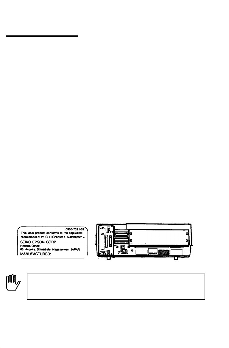
CDRH Regulations
The Center for Devices and Radiological Health (CDRH) of the
U.S. Food and Drug Administration implemented regulations for
laser products on August
products manufactured from August
mandatory for products marketed in the United States. The label
shown below indicates compliance with the CDRH regulations and
must be attached to laser products marketed in the United States.
2, 1976.
These regulations apply to laser
1, 1976.
Compliance is
WARNING: Use of controls, adjustments or performance
of procedures other than those specified in this manual
may result in hazardous radiation exposure.
Page 7

Internal Laser Radiation
Maximum Radiation Power
WaveLength
..............................
.............
2.42
780
(nm)
This is a Class IIIb Laser Diode Assay that has an invisible laser
beam. The printer head unit is NOT A FIELD SERVICE ITEM.
Therefore, the printer head unit should not be opened under any
circumstance.
X 10
-4
(W)
Ozone Emission
During printer operation, a small amount of ozone is released. This
amount is not large enough to affect human beings adversely.
However, it is best to make sure the room where you a using the
printer has adequate circulation, especially if you are printing a
high volume of materials or using the printer continuously over a
long period of time.
vi
Page 8

Contents
Introduction
Finding Your Way Around
Chapter 1 Setting Up the Printer
Finding a Place for the Printer
Unpacking the Printer
Assembling
the
Printer..
............................................................
.........................................................
.............................................. 1-2
Chapter 2 Testing and Connecting Your Printer
The
Control
Testing the Printer
Connecting to Your Computer
Panel..
.................................................................
..................................................................
..............................................
Chapter 3 SelecType
SelecType Overview
Using SelecType
Selecting Channel and Mode
SelecType Options
Choosing a Font
Using the SUB
...............................................................
......................................................................
................................................
..................................................................
......................................................................
CONFIG. Option
......................................... 3-38
1
8
1-1
1-6
1-11
2-1
2-2
2-6
2-17
3-1
3-2
3-5
3-12
3-15
3-36
Chapter 4 Paper Handling
Choosing Paper
Choosing a Paper Size
Printing Methods
Loading Paperinthe
Loading Paper
.......................................................................
............................................................
....................................................................
Cassette..
Manually..
......................................................
.............................................
Contents
4-1
4-2
4-5
4-6
4-9
4-13
vii
Page 9

Chapter 5 Application Software
5-1
Using Your Printer with Application Software ......................
Controlling the Printer
............................................
Chapter 6 Maintenance and Transportation
TONER
Routine
Transporting
LOW Message .........................................................
Cleaning ....................................................................
Your Printer
................................................
Chapter 7 Troubleshooting
Status
and Error
Troubleshooting
Jam
Paper
Power Supply
Print
Test
Printing
Problems
SelecType
Paper
Decline
Options
Data
Problems................................................................
..........................................................................
.................................................................................
Problems
with
Problems................................................................
Handling
in
Print
....................................................................................
Dump
Mode...................................................................
Messages..
Directory..
...................................................................
Graphics..
.......................................................................
Quality
...................................................
...................................................
.......................................................
........................................................
5-2
5-5
6-1
6-2
6-14
6-22
7-1
7-2
7-10
7-12
7-20
7-21
7-22
7-26
7-28
7-31
7-36
7-43
7-48
Chapter 8 Technical Specifications
Printer
Interface
Initialization..
Option
viii
Specifications.. ............................................................
Specifications..
.........................................................
...........................................................................
Specifications .............................................................
Contents
8-1
8-2
8-9
8-16
8-21
Page 10

Appendix A Options
The
The
The Face-up
The Memory Options
The Memory
The Memory
Cartridges..
Font
Lower Paper
Output
Chip
Expansion
.............................................................
Cassette
Tray
Set
A-1
A-2
....................................................
.................................................... A-24
........................................................... A-30
..........................................................
Boards..
.........................................
A-10
A-32
A-42
Appendix B Character Samples and Symbol Sets
Available Fonts and Symbol Sets
HP Emulation Mode
LQ
and
Converting Hexadecimal Numbers to
Emulation
FX
..............................................................
Modes
........................................
..............................................
Decimals
................
Appendix C Printer Modes
Available Printer Modes
HP Emulation
LQ and FX Emulation Modes
Mode..
.......................................................
............................................................
..............................................
Glossary
Index
B-1
B-2
B-4
B-12
B -16
C-1
C-2
C-3
C-11
GL-1
IN-1
Contents ix
Page 11

Introduction
The EPL-7000 is the latest in Epson’s advanced line of laser
printers, combining high performance and reliability with a wide
range of features.
The EPL-7000 combines a semiconductor laser with the
electrophotographic technology used in office copiers to give you
high-quality printing that is both fast and quiet.
The imaging system used by the printer is driven by a powerful
processor that allows the printer to compose an entire page in
internal memory before printing. The printer can manipulate the
page it holds in memory to provide you with many features not
found on other types of printers, including the ability to mix text
and graphics, create pre-defined forms, and print with a range of
fonts normally associated with typeset material.
Features
In addition to the high-quality printing and easy operation you’d
expect from an Epson printer, these features make the EPL-7000
your best choice for today’s printing:
High quality 300 dots-per-inch (dpi) printing at a speed of up
to six pages per minute. You’ll appreciate the crisp, professional
print quality produced by the EPL-7000... and its leading edge
processing speed.
0.5 Megabytes of standard Random Access Memory (RAM).
You can expand the printer’s RAM up to 6 Megabytes with
easy-to-install memory chip sets and optional memory boards.
HP LaserJet series IIP™
application programs written specifically for Hewlett-Packard
LaserJet printers.
emulation. Access the variety of
®
Introduction 1
Page 12

Introduction
14 resident outline fonts to generate and download character
fonts in a wide range of sizes. These fonts provide the same
character widths used by Adobe PostScript™.
A standard paper cassette that holds up to 250 sheets of paper.
Add the optional lower cassette, which holds an additional 250
sheets, and print up to 500 pages continuously.
Three built-in interfaces. Choose Centronics
®
parallel, RS-232
serial, or RS-422 serial.
Two independent interface channels. Add optional memory and
share the printer by connecting it to two computers at the same
time. You can store customized configurations in separate
channels.
An all-in-one imaging cartridge that combines the
photoconductive, developing, and toner unit in a single,
disposable cartridge. Replace it in minutes for simple printer
maintenance.
Two paper delivery methods. Choose standard face-down
delivery for your everyday printing needs, or add the optional
face-up tray for printing on special media like lables or very
heavy paper.
A SelecType control panel for easy configuration control.
Customize your printer’s interface and communication setitngs
with the touch of a button from the printer’s front panel to
create the system that’s right for you.
Two Epson ESC/P® emulation modes for compatibility with the
range of applications software written for Epson 9-pin and
24-pin printers.
2
Introduction
Page 13
Introduction
Options
Many printer options are available for your printer. For detailed
information on the installation and use of these options, see
Appendix A.
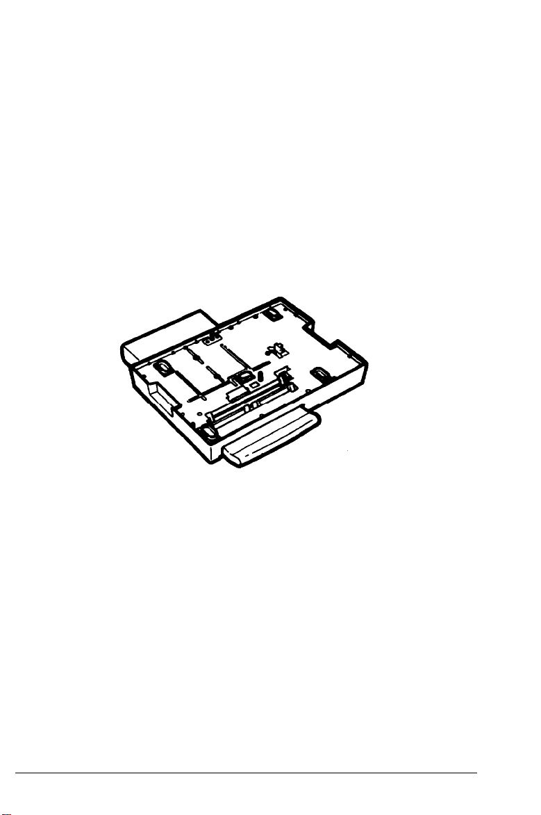
The lower paper cassette (C812051)
The optional lower paper cassette fits directly beneath the printer
and allows you to feed up to 250 sheets of paper into the printer.
The optional cassette supplements your standard paper cassette’s
250-sheet capacity.
Introduction 3
Page 14

Introduction
The face-up output tray (C812071)
The face-up output tray delivers paper face-up for immediate
viewing of your printed output. Use the face-up output tray for
printing that requires a straight-through paper path, such as labels,
heavy paper, and overhead transparencies.
Interface cables
Epson supplies several types of interface cables as listed below.
See your computer manual for the required cables.
Cable
C836022 Parallel
C836041
C836061
4
Introduction
Interface
Serial
Serial
Printer side
Amphenol 57
D-SUB, 25 pin
D-SUB, 25 pin
Computer side
D-SUB, 25 pin
D-SUB,
D-SUB,
25 pin
9 pin
Length
2m
2m
2m
Page 15
Introduction
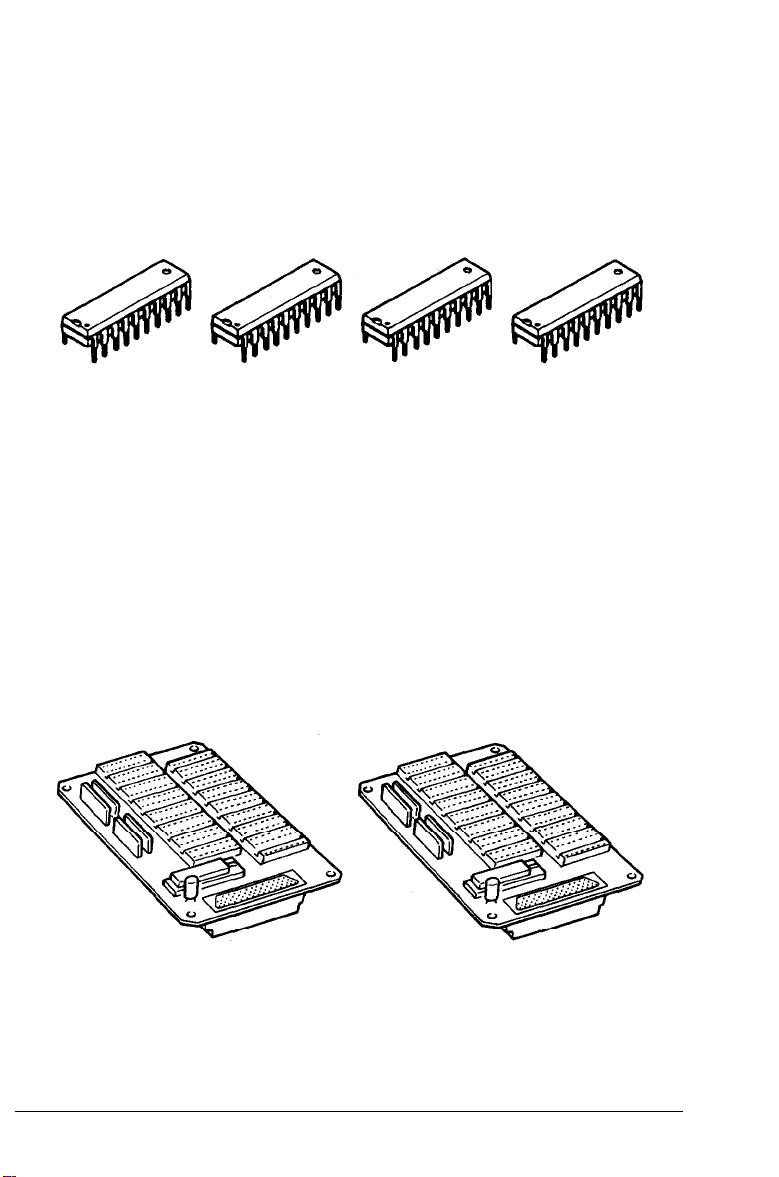
Memory chip set (#5900, C829041)
You can increase your printer’s current 0.5 MB of RAM to a total
of 2.0 MB by installing memory chip sets. Each set of four RAM
chips increases the printer memory by increments of 0.5 MB.
Memory expansion boards (C822011, C822031)
Two optional memory expansion boards are available to
supplement your printer’s memory. The economical C822031
memory board comes with a standard .5 MB of additional RAM.
Add memory chip sets to this board and increase your printer’s
RAM to 4.5 MB, enough memory to print complex graphics.
The more powerful C822011 memory board comes with a standard
2 MB of additional RAM. Add memory chip sets to this board and
you can increase your printer’s RAM to a total of 6 MB
the most demanding print jobs.
to handle
Introduction 5
Page 16
Laser Printer Precautions
This printer uses laser technology. The following list of precautions
applies whenever you open the printer cover. Even if you are
familiar with other types of printers, be sure to follow these
precautions carefully to ensure safe, efficient operation.
l Be careful not to touch the fuser, which is marked by a
CAUTION: HOT SURFACE label. If the printer has been in
operation, the fuser can be very hot.
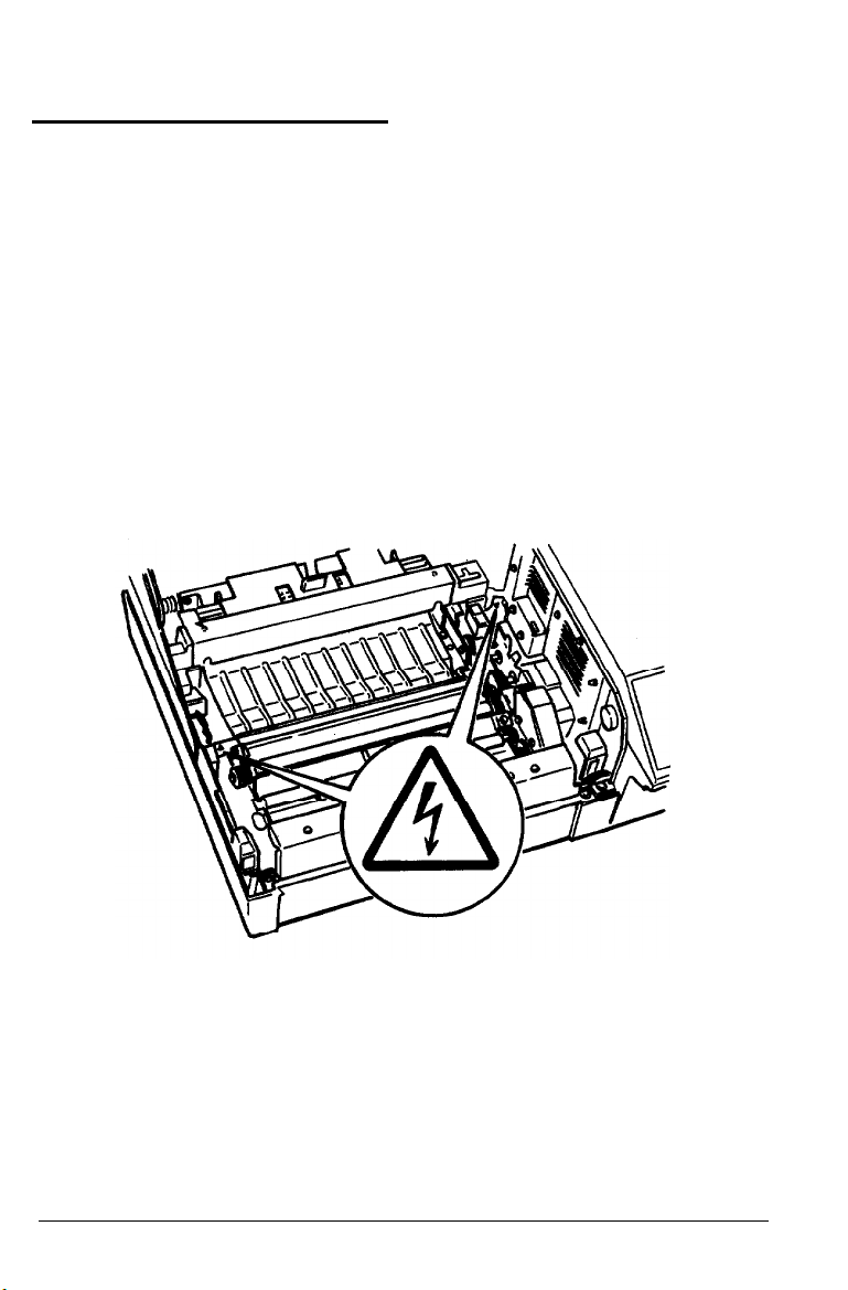
l High voltages are present inside the printer when the power is
on. Do not touch the areas marked by a high voltage label, as
shown below.
l Protect the light-sensitive drum from exposure to light. You
should avoid exposing the imaging cartridge to room light for
any longer than necessary. Do not open the drum’s protective
cover. Overexposing the drum may cause abnormally dark or
light areas to appear on the printed page, reducing the service
life of the drum.
Laser Printer Precautions
6
Page 17

Laser Printer Precautions
If you must expose the drum either by taking the imaging
cartridge out of the printer or by leaving the printer cover
open, cover the drum with a soft cloth or sheet of paper.
l Be sure not to scratch the surface of the drum. When you
remove the imaging cartridge from the printer, always set the
cartridge on a clean, smooth surface. Also, avoid touching the
drum, since oils from your skin can permanently damage its
surface and may affect print quality.
l Avoid pressing on the top of the toner cartridge. Pressing
directly on the cartridge may cause toner to spill into the
printer. If there is a spill, see Chapter 6 for cleaning
instructions.
l Never try to force the printer’s components into place.
Although the printer is designed to be sturdy, rough handling
can damage it.
Laser Printer Precautions
7
Page 18

Finding Your Way Around
This user’s manual provides fully illustrated, step-by-step
instructions on setting up and operating your printer.
Chapter 1 contains information on unpacking and setting up the
printer. Be sure to read and follow these instructions first.
Chapters 2 and 3 contain information on using the control panel,
testing and connecting the printer, and general operation. The
information on SelecType options in Chapter 3 is necessary for the
day-to-day operation of your printer.
For a detailed discussion of paper handling, see Chapter 4. Make
sure you read this chapter before purchasing your paper supply.
Chapter 5 contains information on using the printer with software,
while Chapter 6 gives you information on maintaining your
printer.
If the printer does not operate properly or the printed results are
not what you expect, see Chapter 7 for troubleshooting tips.
Other chapters contain information on technical specifications,
printer options, printer modes, and configuring the interfaces. The
appendixes contain a list of available symbol sets and character
samples. You will also find a glossary of printer terms and an
index.
At the back of this guide is a Quick Reference card showing all
SelecType menus and options. The SelecType menu maps found
on this card can be used as guides whenever you enter SelecType.
On the back cover foldout are illustrations identifying the different
parts of your printer. You can refer to these as you set it up.
Finding Your Way Around
8
Page 19
Finding Your Way Around
Warnings, Cautions, and Notes
WARNING: must be followed carefully to avoid bodily
injury.
CAUTION: must be observed to avoid damage to your
equipment.
Note: contain important information and useful tips on the
operation of your printer.
Where to Get Help
Epson America provides local customer support and service
through a nationwide network of authorized Epson dealers and
Service Centers.
Epson also provides the following support services through the
Epson Consumer Resource Center at (800) 92243911:
Assistance in locating your nearest Authorized Epson Reseller
or Service Center
Technical assistance with the installation, configuration, and
operation of Epson products
Epson technical information library fax service
Product literature with technical specifications on our current
and new products
Sales of ribbons, supplies, parts, documentation, and accessories
for your Epson product
Customer Relations.
Finding Your Way Around
9
Page 20

Chapter I
Setting Up the Printer
the
a
Finding
Opening the printer cover
Unpacking the Printer
Carrying
Assembling the Printer
Installing the cleaning pad
Installing the imaging cartridge
Installing the paper cassette
Attaching the power cord
Place
for
the printer..
Printer..
............................................................
..........................................................
...........................................................
............................................
.................................................
.................................................
.........................................
...............................................
..................................................
1-2
1-4
1-6
1-10
1-11
1-11
1-13
1-19
1-21
Setting Up the Printer
1-1
Page 21

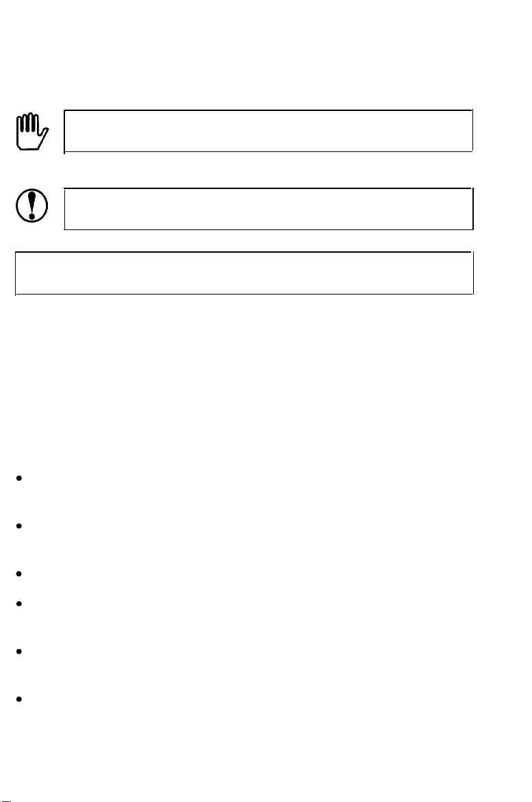
Finding a Place for the Printer
Before unpacking the printer, you need to find a suitable place to
use it. Keep the following points in mind when selecting a place
for your printer:
Place the printer on a flat, stable surface.
Place the printer close enough to the computer or workstation
for its cable to reach.
Use a grounded outlet, one that has three holes to match the
power plug on the printer. Do not use an adapter plug.
Leave adequate room around the printer to allow easy printer
operation and maintenance. The diagram below shows the
amount of space recommended.
1-2
Setting Up the Printer
Page 22
Finding a Place for the Printer
•
If you install the optional face-up tray, you need 16 inches
(400 mm) of space behind the printer. Make sure there is 13
inches (330 mm) of flat, unobstructed space to the left of the
printer
to accommodate the tray.
l To give you enough room to open the printer cover, allow 17
inches or 430 mm from the bottom of the printer to any shelf
or surface directly above the printer, as shown below.
Setting Up the Printer
1-3
Page 23
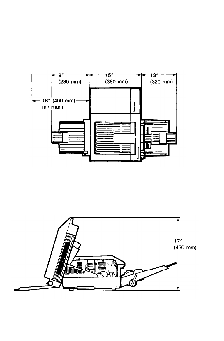
Finding a Plarc for the Printer
If you install the optional lower paper cassette, you need an
additional 4 inches
(100
mm) directly above the printer.
CAUTIONS:
Avoid locations that are subject to direct sunlight,
excessive heat, moisture, or dust.
Avoid using electrical outlets that are controlled by
wall switches or automatic timers. Accidental
disruption of power can wipe out valuable
information in your computer’s memory and printer’s
memory.
Avoid using outlets on the same circuit with large
motors or other appliances that might disturb the
power supply.
Keep the entire computer and printer system away
from potential sources of interference, such as
loudspeakers or the base units of cordless telephones.
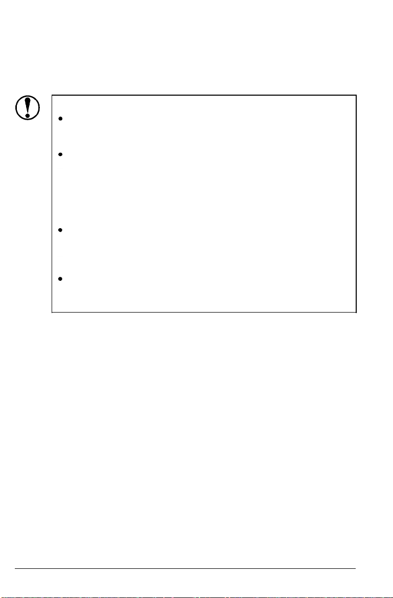
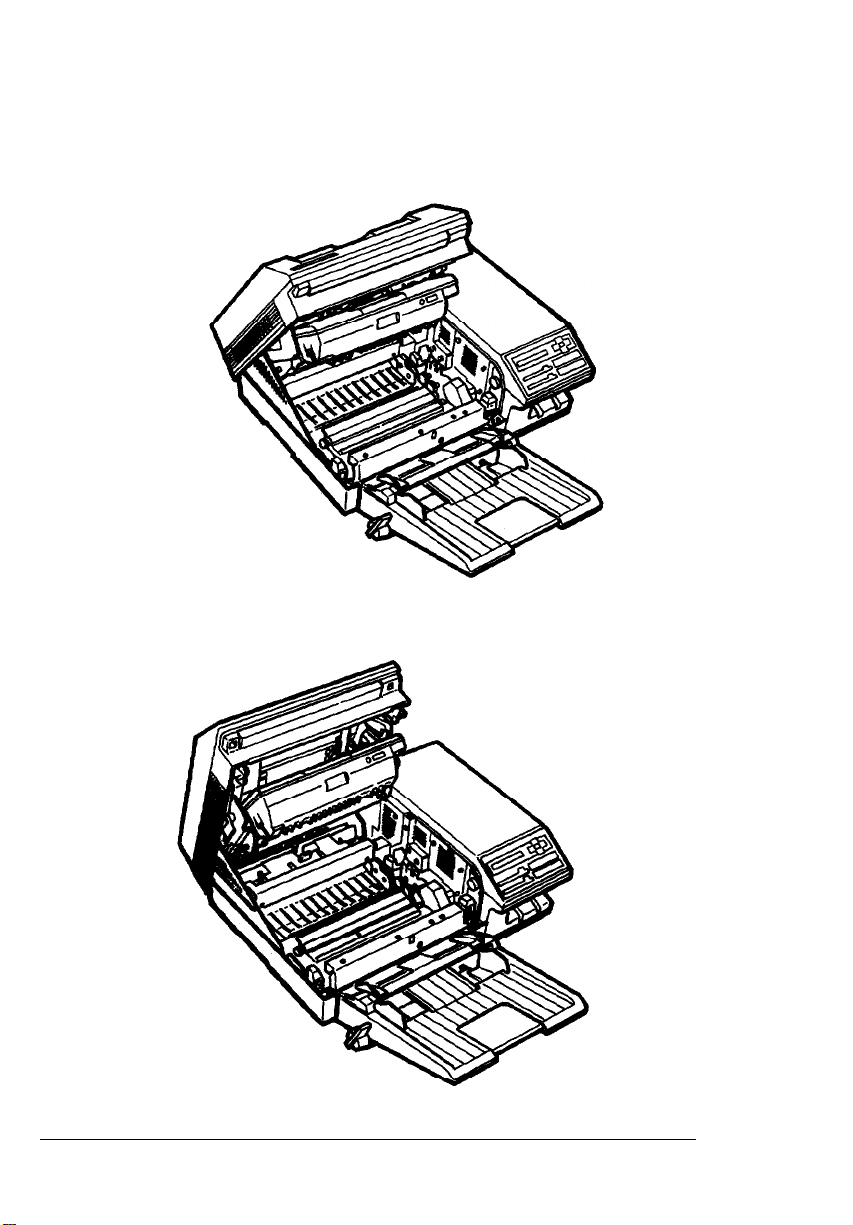
Opening the printer cover
The printer cover opens to two positions, as shown on the
following page. When you lift the latch to open the printer cover,
it stops automatically in the lower position (at an angle of about
45 degrees). This position protects the imaging cartridge from
overexposure to light. When you lift the cover as far as it will go,
it stops at the upper position (about 70 degrees). The instructions
in this manual tell you which position to use for each task.
1-4
Setting Up the Printer
Page 24
Lower position (45°)
Upper position (70°)
Finding a Place for the Printer
Setting Up the Printer
1-5
Page 25

Unpacking the Printer
The printer and the imaging cartridge are packed separately. First,
carefully unpack the large main carton. At the top of the carton is
the accessory pack containing several printer components.
Under this is the printer itself, which is protected by white
packing material.
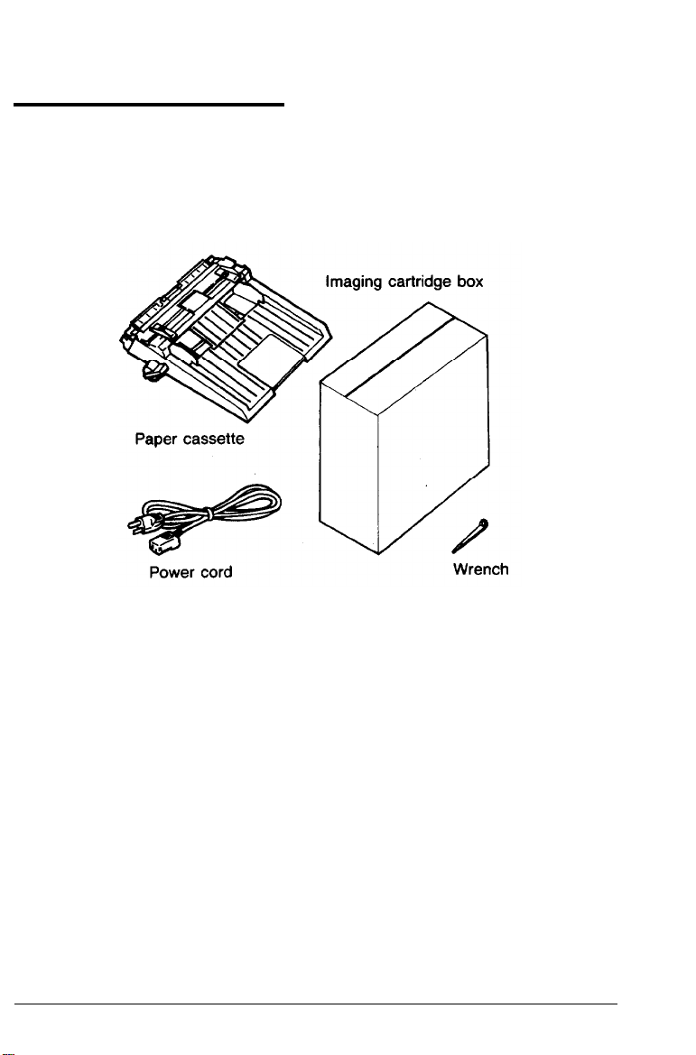
1.
Remove the accessory pack and make sure you have the
accessories shown below.
1-6.
Setting Up the Printer
Page 26

Unpacking the Printer
2.
Carefully remove the printer from the large carton and set it on
a flat, stable surface. Since the printer is heavy, you may need
someone to help you lift it.
3.
Remove the plastic bag protecting the printer. Then remove the
plastic bag from the paper cassette.
Note: Make sure that you save all packing materials. You must
repack the printer in these materials whenever you transport it.
See Chapter 6 for details on transporting your printer.
Setting Up the Printer
1-7
Page 27

Unpacking the Printer
Remove the tape from the printer and the paper cassette.
4.
Use the wrench to unscrew the two screws on the front of the
5.
printer, as shown below.
1-8
Setting Up the Printer
Page 28
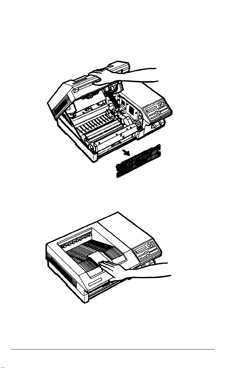
Unpacking the Printer
Lift up the front latch and open the printer cover as far as it
6.
will go, as shown below. Remove the protective plate.
7.
To close the printer, gently press down on the top of the case
until the latch clicks shut.
8.
Finally, check to see that neither the printer nor any of the
accessories has been damaged during transportation.
Setting Up the Printer
1-9
Page 29

Unpacking the Printer
Carrying the printer
When you move your printer to the location you selected for it,
carry it by grasping the recesses on each side of the printer, as
shown below.
Note: The printer weighs about 40 lb. (18kg) and should be
carried with care. You may need someone to help you lift it.
1-10
Setting Up the Printer
Page 30
Assembling the Printer
Before you can use the printer, you need to install a few important
parts. Make sure your printer is at its operating location before
you install the parts.
Installing the cleaning pad
The first component that you need to install is the cleaning pad.
It is packaged inside the imaging cartridge box. The felt cleaning
pad cleans the surface of the fusing roller, which fixes toner onto
the paper.
Setting Up
the
Printer 1-11
Page 31

Assembling the Printer
1.
Open the imaging cartridge box and take out the cleaning pad.
Leave the imaging cartridge, cotton swab, and packing materials
inside the box for now; you will use them later.
Imaging cartridge
2.
Lift up the front latch and open the printer cover to the upper
Cleaning pad
Cotton swab
position, as shown below.
1-12
Setting Up the Printer
Page 32

Assembling the Printer
WARNING: Never touch the fuser. When the printer is
in operation, the fuser becomes very hot.
3.
Hold the cleaning pad by the yellow handle and place the
cleaning pad into the indentation on top of the fuser. To make
sure you install the pad in the correct position, match the
triangle on the cleaning pad with the triangle on the fuser, as
shown below.
Installing the imaging cartridge
The imaging cartridge forms the image and transfers it onto the
paper. See Chapter 6 for information on imaging cartridge life.
CAUTION: The drum is light-sensitive. Do not expose it
to light any longer than necessary and do not expose it
to light brighter than normal room light.
Setting Up
the
Printer
1-13
Page 33

Assembling the Printer
Handling the imaging cartridge
Keep the following cautions in mind whenever you handle the
imaging cartridge:
l Do not turn the cartridge upside down.
l Do not open the drum’s protective cover. Do not scratch or
mar the surface of the drum. Also, do not touch the drum,
since oils from your skin can permanently mar its surface and
may affect print quality.
1-14
Setting Up the Printer
Page 34

Assembling the Printer
Do not expose the cartridge to direct sunlight. If you must
expose the drum, first cover it with the aluminum packing bag
provided or a soft cloth.
When handling the imaging cartridge, always set it on a clean,
smooth surface.
Do not attempt to modify or take apart the cartridge. It cannot
be refilled.
Do not use a cartridge for at least one hour after moving it
from a cool to a warm environment.
Storing the imaging cartridge
Follow these storage precautions to get the best print quality from
your imaging cartridge:
l Do not store in direct sunlight.
l Do not store in dusty places.
•
Do not store where salty air or corrosive gasses (such as
ammonia) are present.
l Do not store where the temperature or humidity are high or
subject to abrupt changes.
Setting Up the Printer
1-15
Page 35

Assembling the Printer
Follow these steps to install the imaging cartridge:
1.
Remove the imaging cartridge from its aluminum packing bag.
CAUTION: Do not open the drum’s protective cover. It
protects the drum from light and contact.
2.
Hold the imaging cartridge as shown below and shake the
cartridge from side to side a few times to distribute the toner.
1-16
Setting Up the Printer
Page 36

Assembling the Printer
3. Pull the yellow tab firmly, as shown below, to remove the clear
seal completely.
After you remove the seal, gently shake the imaging cartridge
4.
again four or five times.
Setting Up the Printer
1-17
Page 37

Assembling the Printer
5. Make sure the printer cover is in the lower position.
6. Hold the imaging cartridge as shown below. Carefully place the
plastic runners on either side of the cartridge into the green
grooves inside the printer. Slide the cartridge forward as far as
it will go.
1-18
Setting Up the Printer
Page 38

Assembling the Printer
7.
Now that you have installed the internal components, close the
printer and gently press down on the top of the case until the
latch clicks shut.
CAUTION: Never transport the printer with the imaging
cartridge installed. See Chapter 6 for details on moving or
transporting the printer.
Installing the paper cassette
Before you install the paper cassette, make sure you have removed
the packing tape from the cassette.
Setting Up the Printer
1-19
Page 39

Assembling the Printer
Locate the paper cassette opening at the front of the printer. Align
the small notches on either side of the paper cassette with the
metal pins inside the printer; then lower the paper cassette into
place, as shown below.
Note: Make sure the notches fit securely onto the pins on the
printer. If the paper cassette is not installed properly, a PAPER
OUT error may appear on the display.
1-20
Setting Up the Printer
Page 40

Assembling the Printer
Attaching the power cord
Before you attach the power cord, make sure the power switch
1.
at the rear of the printer is turned off. It is off when the O on
the switch is pressed toward the printer, as shown below.
WARNING: If the rated voltage of the printer and your
outlet voltage do not match, contact your dealer for
assistance. Do not plug in the power cable.
Setting Up the Printer
1-21
Page 41

Assembling the Printer
Insert the power cord into the socket at the back of the printer,
2.
as shown below. Then plug the other end of the power cord
into a properly grounded outlet.
1-22
Setting Up the Printer
Page 42

Chapter 2
Testing and Connecting Your Printer
The
Control
Display
Indicator lights
Buttons
Testing
Loading paper for a test print
Turning on the printer
Selecting and running a test print
Printingastatus
Adjusting the print density
Connecting the
Sharing the printer
Choosing
Connecting
Connecting
Panel..
.................................................................................
.................................................................................
the
Printer..
an
.................................................................
....................................................................
................................................................
.......................................................
sheet..
PrintertoYour
interface.........................................................
the parallel
the serial
......................................................
..............................................................
interface
interface
...........................................
....................................
...............................................
Computer..
cable
cable................................
........................
............................
2-2
2-2
2-3
2-4
2-6
2-6
2-9
2-10
2-13
2-14
2-17
2-17
2-18
2-18
2-20
Testing and Connecting Your Printer
2-1
Page 43

The Control Panel
The printer control panel gives you easy control over many printer
operations. The panel is made up of three elements: buttons,
indicator lights, and a liquid crystal display. You use the buttons
to select printer settings and functions, and the indicator lights and
display show the current status of the printer.
Display
The display shows the printer’s status and available options. The
types of information displayed are given below.
Status messages, such as WARMING UP, indicate the printer’s
l
current status.
Maintenance and error messages, such as PAPER OUT, inform
l
you of maintenance procedures that must be performed or of
error conditions.
SelecType options, such as MODE, allow you to control printer
l
mode, font selection, paper handling, and many other printer
functions.
For information on using SelecType, see Chapter 3. For a complete
list of maintenance and error messages, see Chapter 7.
2-2 Testing and Connecting Your Printer
Page 44

Indicator lights
The Control Panel
LEVEL 1, LEVEL 2
ON LINE
CONTINUE
CH S, CH P
One of these lights is on when the printer is in
the SelecType mode, depending on which level
you enter. These lights are off if the printer is not
in SelecType mode.
On when the printer is on line, indicating that the
printer can receive and print data, off when the
printer is off line. The light flashes as the system
switches from on line to off line status.
Flashes when an error is detected or a
maintenance procedure must be performed. At the
same time, an error or maintenance message
appears on the display.
One of these lights goes on when data is received
by the indicated channel and is stored in the
printer without being printed -out. The CH S light
goes on if you are using the serial interface. The
CH P light goes on if you are using the parallel
interface. A flashing light indicates that the
printer is receiving data from the computer.
Testing and Connecting Your Printer 2-3
Page 45

The Control Panel
Buttons
You use these four arrows to select and set
printer options in SelecType mode. Their
functions are described in detail in Chapter 3.
FEED
ON LINE
CONTINUE
COPY END/RESET
2-4
Testing and Connecting Your Printer
When the printer is off line and the CH P or
CH S light is lit, press this button to print out
received data. If you use both channels, you
can print data received by either channel. If you
press
or the ON LINE button, the
printer returns to its previous status without
printing data.
Switches the printer between on line and off
line status. This switch is disabled when you
are in SelecType mode.
This button has three functions, so it has three
names.
CONTINUE — Enables the printer to resume
printing after some error or maintenance
Page 46

The Control Panel
messages. If the CONTINUE light is flashing, read
the corresponding error or status message on the
display and correct the problem as described in
Chapter 7.
COPY END — Cancels the remaining copies during
multiple-copy printing. This button is effective
only when the printer is off line.
RESET — Cancels some settings made with
SelecType or software commands. When you hold
down this button for several seconds, ‘RESET
appears on the display and all settings return to
their previously saved values. The page being
printed when this button is pressed is finished.
However, all remaining data is discarded. If you
press
or
, the printer returns to its
previous status without printing data.
If you continue to hold down this button after
RESET appears, INITIALIZE appears on the
display and the printer settings return to the
power-on default settings.
SelecType
Enters or exits SelecType mode. Press once to
enter Level 1; hold down to enter Level 2. When
you enter each level, the corresponding indicator
light goes on. For a complete description of
SelecType, see Chapter 3.
Other control panel features
Data dump
Hold down the SelecType button while you turn on
printer to turn on data dump (or hex dump)
mode. This feature allows advanced users to find
the cause of communication problems between the
computer and the printer. See Chapter 7.
Testing and Connecting Your Printer
2-5
Page 47

Testing the Printer
The printer has two built-in print tests: the self test and the status
sheet. These tests let you check the operation of your printer and
print a list of current printer settings. Before running a test, make
sure you have removed all packing materials from the printer, as
described in Chapter 1, and that you have installed all of the
components.
You do not need to connect the printer to your computer to run
these tests.
Loading paper for a test print
The standard paper cassette can automatically feed up to 250
sheets of paper. To load paper, follow the steps below. See
Chapter 4 if you need more information on paper handling.
1. Push the paper set lever forward to the manual position.
2-6 Testing and Connecting Your Printer
Page 48

Testing the Printer
Slide the paper guides all the way open, as shown below.
2.
3. Take a stack of A4 or letter-size paper (high-quality copier
paper is recommended) and tap the edges of the paper on a flat
surface to even up the stack.
Testing and Connecting Your Printer
2-7
Page 49

Testing the Printer
4.
Insert the stack of paper into the paper cassette, making sure
that the top of the stack does not exceed the maximum height
mark inside the cassette, as shown below. Gently push the
paper in as far as it will go.
5.
Slide the paper guides together until they both rest lightly
against the paper.
2-8
Testing and Connecting Your Printer
Page 50

Testing the Printer
6.
Pull the paper set lever back to the automatic position.
Note: The paper set lever must be in the automatic position
before paper can be fed automatically from the paper cassette. If
you set the lever to the manual position when the printer is on,
automatic paper feeding is disabled and the PAPER OUT
message appears on the display, even if there is paper in the
paper cassette.
Now you’re ready to turn on the printer and run a test print.
Turning on the printer
Make sure the printer is plugged in and the imaging cartridge is
installed; then turn on the power by pressing the vertical bar
on the power switch located at the back of the printer. All of the
lights on the control panel light briefly at power on.
Testing and Connecting Your
Printer
2-9
Page 51

Testing the Printer
The following messages appear as the printer performs a series of
internal tests and warms up:
CAUTIONS:
l Do not open the printer cover while the printer is
warming up or printing.
l After you turn off the printer, always wait at least
five seconds before turning it back on.
It takes approximately 70 seconds for the printer to complete its
power-on routine. When the READY message appears, you can
continue with the test print operation. If the display remains
blank, see Chapter 7 for troubleshooting information.
Selecting and running a test print
The printer has two SelecType levels. The status sheet feature is in
SelecType Level 1 and the test print feature is in Level 2.
2-10
Testing and Connecting Your Printer
Page 52

Testing the Printer
Note: For a complete description of SelecType levels and
functions, see Chapter 3. You may also find the Quick Reference
card located at the back of this manual useful as a guide
whenever you use SelecType.
Follow these steps to select and run the test print:
1.
Hold down the SelecType button until the LEVEL 2 indicator light
goes on and TEST PRINT appears on the display.
If you have entered SelecType before, TEST PRINT may not be
the first option to appear. If the Level 2 indicator is on, you can
press the up or down arrow until TEST PRINT appears on the
display. Then go on to step 2.
If you did not hold down the button long enough to enter Level 2,
the LEVEL 1 indicator goes on. If this happens, press the SelecType
button once to exit SelecType and repeat step 1.
2. Press once. The display reads as follows:
3. To run the test, press once more. The printer prints a test
pattern of vertical lines and ejects the page face-down on top
of the printer.
CAUTION: Never open the printer cover during printing.
Testing and Connecting Your Printer
2-11
Page 53

Testing the Printer
Part of a typical pattern 1 test print is shown below:
After the page has been printed, the printer returns to the main
menu and the display shows TEST PRINT.
If you want to print the second test print pattern, follow these
additional steps:
4. Press I,( once; then change the test pattern number by
pressing or once to display the following:
5. Press I,( to print the second pattern.
After you print the test pattern, press SelecType once to exit
SelecType mode.
If the test pattern prints correctly, you can skip to the section on
connecting the printer to your computer later in this chapter. If the
test print does not operate properly, see Chapter 7 for
troubleshooting information.
2-12
Testing and Connecting Your Printer
Page 54

Testing the Printer
Printing a status sheet
In addition to the test print patterns, you can print a status sheet
that lists printer settings for your selected channel.
Note: The status sheet prints the printer’s current settings. If
you change the macro number setting for the LOAD MACRO
option in the SYSTEM CONFIG submenu, the status sheet
prints out the new macro settings. MACRO 0 is the factory
default setting.
Follow these steps to print the status sheet:
1.
Make sure that your printer is plugged in and the power is on.
2.
Press SelecType once to enter SelecType Level 1.
Note: If you have used SelecType before, and if the printer is
set up to use both channels, the following option appears on the
display:
Press or to choose your channel, then go on to step 3.
3. Hold down until STATUS SHEET appears on the
display.
4. Press to print the status sheet.
Testing and Connecting Your Printer
2-13
Page 55

Testing the Printer
A portion of the status sheet printout is shown below.
Printer Configuration
Installed Memory : 0.5kbytes
Memory Share
Auto Continue
standby
:
P
CH
Mode
I/F :
PARALLEL
PARALLEL (CH P)
SLCTIN
SERIAL (CH S) : RS232C
word Length(bit) : 8
Stop Bit
DSR
Receive Buffer
Mode Configuration
Input Tray
Copies
Sub Configuration
Form Length : 60
: OFF
: 2
: OFF
: 1kbytes
: AUTO
: 1
: S 0:10P
: OFF
: DISABLE
: L-JET2P
AUTOFEED
Baudrate(bps) : 9600
DTR
CTS
Font
orientation : PORT
Symbol Set
STATUS SHEET
:
Controller Version : 02.07 06.03
CH Time out
Beeper
Version
: OFF
: ON
: OFF
: RD-0
BUSY Delay(µ6) : 0
Parity
XON/XOFF
ENQ/ACK
Paper Size
EPSON
: 10
: ON
: 09.36
: LETTER
: NONE
: ON
: OFF
Adjusting print density
You can control the overall density of the printed image with the
print density control knob. If your test print is too light or too
dark, adjust the print density as follows:
1.
Lift the latch to open the printer cover to the lower position.
2-14 Testing and Connecting Your Printer
Page 56

Testing the Printer
Find the yellow density control knob inside the front right
2.
corner of the printer, as shown below.
For darker print, turn the knob clockwise as shown.
3.
AA
Note: Increasing the print density increases toner consumption.
If you select darker print, you may need to replace the imaging
cartridge more often.
Testing and Connecting Your Printer
2-15
Page 57

Testing the Printer
4. For lighter print, turn the knob counterclockwise as shown.
AA
Note: If you want to return the print density setting to the
factory setting (center position), align the vertical line on the
knob with the dot on the scale.
5. Close the printer cover.
6.
Run the test print again to check the new print density setting.
2-16
Testing and Connecting Your Printer
Page 58

Connecting the Printer to Your Computer
For the printer to receive and interpret information from your
computer, both devices must be set up so they can communicate
properly. This requires the correct interface cable and the right
communication setting. You can select from the following built-in
interfaces:
l
l RS-232C/RS-422 serial
Centronics
®
compatible parallel
Sharing the printer
One of the unique features of your printer is that you can connect
it to two different computers at the same time. Simply use the
serial interface for one computer and the parallel interface for the
other. Once you have connected the interfaces, you use SelecType
to divide the printer’s memory between Channel S (serial interface)
and Channel P (parallel interface), and to change serial interface
settings as necessary.
Testing
and Connecting Your Printer
2-17
Page 59

Connecting the Printer to Your Computer
If you want to share the printer, skip the section on choosing an
interface. You must first add memory to your computer’s main
board as described in the section on installing memory chip sets in
Appendix A. Next, follow the instructions in Connecting the
Parallel Interface and Connecting the Serial Interface to connect
each interface; then see Chapter 3 for details on using SelecType to
configure each channel.
Choosing an interface
When connecting the printer to your computer, first determine
whether you should use a parallel or serial connection. Many
computers provide only one type of connection for a printer. If
both types of connections are available, it is usually better to use
the parallel interface for the printer, leaving the serial port of your
computer free for other devices such as modems. If you are in any
doubt about which type of connection to make, consult your
dealer.
The printer is set up for parallel communication at the factory. If
your computer has a parallel interface, you should be able to
connect it to the printer with a properly shielded cable and not
change any factory settings.
If, however, you find that you need a serial interface, you must set
up Channel S with SelecType. You may also need to use SelecType
to change some of the serial settings, such as baud rate or parity,
to suit your needs. See Chapter 3 for instructions on using
SelecType to change printer settings.
Connecting the parallel interface cable
If you want to use the printer’s standard parallel interface, make
sure you have a shielded cable suitable for a Centronics-compatible
interface.
2-18
Testing and Connecting Your Printer
Page 60

Connecting the Printer to Your Computer
1.
Turn off both your printer and computer. Then unplug the
power cord from the electrical outlet.
2.
Plug the connector securely into the parallel interface of the
printer, as shown below.
3.
Squeeze the wire clips together until they lock in place on
either side of the connector.
Testing and Connecting Your Printer
2-19
Page 61

Connecting the Printer to Your Computer
4.
If your cable has a grounding wire, connect it to the printer’s
ground connector as shown.
5.
Plug the other end of the connector into your computer. Some
parallel cables have grounding wires at the computer end as
well. If so, connect this wire to the ground screw on the
computer.
Note: You can use the SelecType CH CONFIG option to change
some of the parallel interface settings. However, you will
probably never need to change these settings.
Now that you have connected the parallel interface, see Chapter 5
for information on operating your printer with your application
program.
Connecting
If you want to use the printer’s standard serial interface, make sure
that you have a properly shielded cable and that it is the correct
one for your printer.
Follow these steps to connect the serial interface cable:
1. Turn off both the printer and computer. Then unplug the
power cord from the electrical outlet.
2-20
the serial interface cable
Testing and Connecting Your Printer
Page 62

Connecting the Printer to Your Computer
Plug the cable connector securely into the serial interface as
2.
shown below.
Use a screwdriver to fasten the screws of the connector, if
3.
required.
Testing and Connecting Your Printer
2-21
Page 63

Connecting the Printer to Your Computer
If your cable has a grounding wire, connect it to the printer’s
4.
ground connector.
Plug the other end of the cable into your computer. (Fasten the
5.
connector screws to the interface, if required.)
This completes the connection of the serial interface cable. Before
you can use the printer, you need to set it up for serial
communication using the SelecType CH CONFIG option in
Level 2. You may also need to change some interface settings, such
as baud rate and parity, before your printer and computer can
communicate properly. See Chapter 3 for instructions on setting up
the serial interface to work with your computer.
2-22 Testing and Connecting Your Printer
Page 64

Chapter 3
SelecType
SelecType Overview
SelecType Level 1 functions
SelecType Level 2 functions
Using SelecType
The
control
The
display
Buttons
panel..
.......................................................................... 3-5
................................................................................. 3-6
Steps to using SelecType
Selecting Channel and Mode
Channels
...............................................................................
Available printer modes
...............................................................
..............................................
..............................................
......................................................................
..............................................................
...................................................
................................................
.....................................................
Setting the channel and printer mode
with the CH CONFIG option
SelecType Options
Level 1 options
Level 2 options
Choosing a Font
HP emulation mode
LQ and FX emulation modes
..................................................................
....................................................................
....................................................................
......................................................................
............................................................
............................................ 3-37
.........................................
3-2
3-3
3-4
3-5
3-5
3-7
3-12
3-12
3-12
3-13
3-15
3-15
3-24
3-36
3-36
Using
the SUB CONFIG.
Option
.........................................
HP emulation mode............................................................
LQ and FX emulation modes
............................................ 3-41
SelecType 3-1
3-38
3-38
Page 65

SelecType Overview
The SelecType function on the printer control panel allows you to
control many of the printer’s functions. Use SelecType’s menubased system to change your printer’s configuration without using
DIP switches and to select most font and print options without
using software commands.
Your application program may send printer commands that
temporarily override the SelecType settings. If you are not getting
the results you expect, check your application software settings,
Note: New SelecType settings are in effect only until you turn
off the printer, unless you save them with the Level 1 SYSTEM
CONFIG option or the Level 2 P-CONFIG.SAVE option
described later in this chapter.
SelecType is divided into two levels as shown below. Level 1
contains everyday printing and font selection functions, and Level
2 contains functions that are less likely to be changed frequently,
such as printer mode and printer configuration. A brief description
of each main menu option follows. See SelecType Options later in
this chapter for detailed descriptions of all SelecType options.
Level 1
CH SELECT
INPUT
P-SIZE
COPIES
ORIENT.
FONT
STATUS SHEET
SUB CONFIG.
SYSTEM CONFIG.
3-2
SelecType
Level 2
TEST PRINT
CH CONFIG
MEMORY SHARE
CH TIMEOUT
AUTO CONT.
BEEPER
P-CONFIG. SAVE
FACTORY RESET
VERSION
STANDBY
Page 66

SelecType Overview
Note: See the Quick Reference Card at the back of this manual
for a map of SelecType menus and options.
SelecType Level
CH SELECT
1 functions
Selects the parallel (P) or serial (S) channel
when you have set up both interfaces.
INPUT
P-SIZE
COPIES
ORIENT.
Selects the standard or optional paper cassette.
Paper size. Specifies the size of paper.
Selects the number of copies to be printed.
Orientation. Selects portrait (vertical) or
landscape (horizontal) printing orientation.
FONT
STATUSSHEET
Selects one of the available fonts.
Prints a report listing the current printer
settings.
SUB CONFIG.
Subconfiguration. Depending on the printer
mode, controls such features as symbol set and
number of text lines.
SYSTEM CONFIG. System configuration. Saves Level 1 settings,
displays the amount of memory remaining,
changes top and left offsets, and controls
printing of complex pages.
SelecType 3-3
Page 67

SelecType Overview
SelecType Level 2 functions
TEST PRINT
CH CONFIG.
MEMORY SHARE
CH TIMEOUT
AUTO CONT.
BEEPER
P-CONFIG. SAVE
Prints two test patterns to check printer
operation.
Channel configuration. Sets up the operating
mode, interface configuration, and the size of
the printer’s input buffer for each channel.
Memory share. Specifies the proportion of the
printer’s memory shared between channel S
and P.
Channel time out. If no data is sent during the
specified time period, the printer switches from
one channel to the other.
Automatic continue. Permits the printer to
continue printing instead of stopping under
certain error conditions.
Turns the beeper on or off.
Printer configuration save. Saves all Level 2
settings as defaults so they take effect each
time you turn the printer on.
FACTORY RESET
VERSION
STANDBY
3-4
SelecType
Returns all Level 1 and Level 2 settings to their
factory settings.
Displays the version numbers of the printer’s
firmware components such as the controller and
font.
Conserves power by reducing power to the
fixing heater when the printer is not used for
30 minutes.
Page 68

Using SelecType
This section describes the control panel and explains how to use
SelecType. If you want to try a guided practice, see the sample
exercise included in Steps to using SelecType, later in this section.
The control panel
The SelecType portion of the control panel contains the SelecType
button, Level 1 and Level 2 indicator lights, four arrow buttons,
and the display.
The display
When you enter SelecType, menus and options appear on the
display. The display shows SelecType main menus on the left side.
On the right side, the display shows the options for each main
menu.
The icons in the display are like road signs — they indicate the
direction you can move using the arrow buttons.
SelecType 3-5
Page 69

Using Selec Type
The
icon (up and down arrows) to the left of
an option indicates that you can press either
or to view other options in the
menu,
The icon to the left of an option indicates
that the option displayed is the current
selection. You can use or to view
other options.
These icons indicate that you can press or
to enter a submenu, select an option, set
an option, or select an action.
Buttons
SelecType
Use the arrow buttons to move through menus and to select,
display, and set SelecType options.
Enters and exits SelecType mode. Press once to
enter Level 1 or hold down to enter Level 2.
The Level 1 or Level 2 light goes on to indicate
which level is active.
3-6
Enter a submenu, set an option, or select an
action.
Return to the main menus.
Display options in the same menu. You can
view the options one at a time by pressing the
buttons once or you can scroll through them
quickly by holding down one of these arrows.
SelecType
Page 70

Using SelecType
Note: If you press an arrow that is invalid, the printer beeps and
does not change the display.
Steps to using SelecType
There are six basic steps to using SelecType:
Enter SelecType mode.
1.
2.
Select channel, if necessary.
Move to the option you want to set.
3.
4.
Set the option.
Save the new setting, if necessary.
5.
Exit SelecType mode.
6.
You’ll see how to complete each step on the following pages. This
section uses the SelecType Level 1 INPUT option to explain the
steps to using SelecType. You may want to try each step as you
read it for hands-on practice.
Enter SelecType mode
SelecType has two levels, Level 1 and Level 2. You can press the
SelecType
Level 2. The Level 1 or Level 2 indicator light goes on to indicate
which level is active.
Press
SelecType
button once to enter Level 1, or hold it down to enter
once to enter SelecType Level 1.
SelecType 3-7
Page 71

Using SelecType
Select channel
If you have connected computers to both interfaces and set the
MEMORY SHARE option, whenever you enter SelecType Level 1,
the display shows the channel select option, as shown below. If
you have not set up both interfaces, SelecType skips this option
and the display shows one of the Level 1 main menu options.
CAUTION: If you have attached a printer to each
interface and want to share the printer, you must add
additional memory to the printer. (See Appendix A.)
Then you must set the MEMORY SHARE option in
Level 2 before you select the channel. If you have not set
the MEMORY SHARE option, CH P is selected.
After you select the channel, one of the main menu options
appears on the display. The printer stores the settings for each
channel separately. The settings you choose for one channel do not
affect the settings of the other.
Move to the desired option
When you enter SelecType Level 1 or Level 2, one of the main
menu options appears on the display. To look at the other options
at this level, you can use the and buttons.
Press until the INPUT option appears on the display, as
shown below.
3-8
SelecType
Page 72

Using SelecTType
The display shows one of the choices in the INPUT option to the
right. Most options have further levels, called submenus, or a list
of choices connected to the option. Some options, like the SUB
CONFIG option, may display only the main option until you enter
the submenu. And some options, like the VERSION option, simply
display information about your printer.
You use the button to enter the next level of an option.
Press to enter the next level of the INPUT option.
indicates that STD is selected, and in some cases a message (SET,
EXEC, or PRINT) appears to the right of the option shown.
In the INPUT option, you can display any of the choices listed
below.
STD
OPT
AUTO
OPT appears only when you install the optional lower paper
cassette.
Press or to move to AUTO. Your display should look
like this:
indicates that the option is not selected and SET indicates that
you can set that option by pressing
SelecType 3-9
Page 73

Using SelecType
Note: Although the main menu options are the same for
all operating modes (LQ, FX, and L-JET2P), some Level 1
submenu options are different in each mode. Submenu options
for each mode are discussed later in this chapter.
Set the option
To set an option, you can simply press
Press to select AUTO. SET disappears from the display and
the icon moves to the right of the display indicating that the
new option has been set.
At the same time, moves to the left of the main menu option,
indicating that you are back in the main menu.
Note: If you want to back out to the main menu at any time
without changing a setting, press
3-10 SelecType
Page 74

Using SelecType
Your new setting remains in effect until you change it again or
turn off the printer.
Save the setting
If you want a setting to remain in effect even when you turn the
printer off and on, you can use the SYSTEM CONFIG option to
save Level 1 settings, and P-CONFIG. SAVE option to save Level 2
settings.
Exit SelecType mode
To exit SelecType mode from any option, press the SelecType
button.
SelecType
3-11
Page 75

Selecting Channel and Mode
Channels
This printer has two channels built-in so that you can connect the
printer to two different computers at the same time and share the
printer.
Channel P is set for parallel communication and Channel S is set
for serial communication. You can store a different group of
settings in each channel.
want to share the printer. See Appendix A for
Once you have installed the additional memory, change the
MEMORY SHARE setting to divide the printer’s memory between
the two channels. Then you can set the printing options for each
channel to meet specific needs. For example, in each channel you
might want to use a different printer mode, or size of printer input
buffer. SelecType options make it easy to customize the settings of
each channel.
Available printer modes
Your printer comes with the following resident printer emulation
modes:
l HP LaserJet series IIP
l Epson LQ-2500
l Epson FX-86e/286e
3-12
SelecType
Page 76

Selecting Channel and Mode
The HP emulation mode offers the widest range of features, but
you may also want to select other modes to use software written
specifically for other printers. You must change the MODE setting
before you can operate your printer as an Epson LQ-2500 or
FX-86e/286e
printer.
Setting
the channel and printer mode with the
CH CONFIG option
To change the channel and the printer mode, first you must set the
rate of printer memory sharing with the MEMORY SHARE option.
Until you set this option, you cannot select Channel S.
CAUTION: Do not change the MEMORY SHARE
option until you have installed additional memory in the
printer. You could damage the printer. See Appendix A
for information an adding memory.
Follow the steps below to change the CH CONFIG option. This
example describes selecting Channel P and setting the printer mode
to LQ emulation mode.
Hold down the SelecType button until you enter SelecType
1.
Level 2. The Level 2 light goes on. One of the Level 2 main
menus appears on the display.
Press or until the CH CONFIG option appears.
2.
Press to enter the CH CONFIG option. The display
3.
shows:
SelecType
3-13
Page 77

Selecting Channel and Mode
If you want to change the channel, press or . If you
4.
do not, press Then you move to a submenu, MODE. The
current setting for HP emulation mode is shown on the display:
5.
Press to enter the MODE option. The icon appears to
the left of the currently set printer mode as shown below.
6.
You can choose either the L-JET2P, LQ, or FX mode. Press
either or until the mode you want to select appears
on the display.
7.
Press to set the new mode. The display returns to the
main menu.
8.
Press the
SelecType
button to exit SelecType.
This mode setting remains in effect until you change the setting
again or turn off the printer. If you want this setting to remain in
effect even after you turn the printer off and back on, use the
P-CONFIG option to save the setting as described later in this
chapter.
3-14 SelecType
Page 78

SelecType Options
This section lists all the options available when you use SelecType.
Most options are the same whether you’re working in L-JET2P,
LQ, or FX emulation mode. Some of the options in Level 1,
however, have a different function for each mode. These options
are listed later in this chapter. See the Quick Reference Card for a
map of all SelecType menus and options.
Level 1 options
When you press
main menu options listed below appears on the display.
INPUT
P-SIZE
COPIES
ORIENT.
FONT
STATUSSHEET
SUB CONFIG.
SYSTEM CONFIG.
Each of these options is described below. An asterisk (*) indicates
the factory default setting for each option.
SelecType
once to enter Level
1,
one of the Level 1
Note: If you have set the MEMORY SHARE option in Level 2,
the display shows CH SELECT whenever you enter Level 1.
After you select the channel, one of the main menu options
listed above appears on the display.
SelecType 3-15
Page 79

SelecType Options
STD
OPT
*AUTO
This option selects whether paper feeds into the printer from the
standard paper cassette or the optional lower paper cassette.
If you choose STD, the printer loads paper from the standard
paper cassette.
If you choose OPT, the printer loads paper from the optional lower
paper cassette. OPT only appears as an option on the display if the
optional lower paper cassette is installed.
If you choose AUTO, the printer loads paper from the paper
cassette containing the size of paper specified by the P-SIZE (paper
size) option. If both cassettes contain the specified paper size, the
printer loads paper from the optional lower paper cassette until it
is empty, then switches to the standard paper cassette.
If the paper in any of the cassettes does not match the paper size
set with P-SIZE option, the printer returns a paper size error.
3-16 SelecType
Page 80

SelecType Options
A4
A5
B5
LETTER
HALF LT
LEGAL
GLT
GLG
EXE
F4
MONARCH
C10
DL
(Half Letter)
(Government Letter)
(Government Legal)
(Executive)
(Commercial
10)
C5
You can choose any of the paper sizes shown above with the
P-SIZE option. The factory setting is LETTER.
1 to 99
Use this option .to print up to 99 copies of your print job. The
factory setting is 1. If you select a number above one, the display
keeps count of the number of copies completed and the current
setting. For example, if you set the copies option to 10 and 5
copies are complete, the display shows 5/10.
SelecType
3-17
Page 81

SelecType Options
PORT
LAND
The orientation option selects the direction in which the characters
are printed on a page. You can choose portrait (vertical) or
landscape (horizontal) orientation.
Available options in the FONT submenu are different for each
printer mode. See Choosing a Font later in this chapter for
information on using this option.
3-18
SelecType
Page 82

SelecType Options
Use this option to print a status sheet that lists the current printer
settings. When you reach this option, press to print the
status sheet.
Printer Configuration
Installed Memory : 0.5Mbytes
Memory Share
Auto Continue
standby : DISABLE
CH
:
P
Mode
I/F :
PANALLEL
PARALLEL (CH P)
SLCTIN
SERIAL (CH S) : RS232C
Word Length(bit) : 8
Stop Bit
DSR
Receive Buffer
Mode Configuration
:
OFF
: S 0:10P
: OFF
: L-JET2P
: 2
: OFF CTS
:1kbytes
STATUS SREET
Controller Version : 02.07 06.03
CH Time out
Beeper
Version
AUTOFEED
Baudrate(bps) : 9600
DTR
: OFF
:ON
:
OFF
BUSY Delay(µs) : 0
Parity
XON/XOFF
ENQ/ACK
EPSON
: 10
: ON
: 09.36
: NONE
:ON
:
OFF
The submenus for the subconfiguration option are different in each
printer mode. See Using the SUB CONFIG Option later in this
chapter for information on using this option.
This option includes the eight submenus shown below.
SelecType
3-19
Page 83

SelecType Options
FULL PRINT
T-OFFSET
L-OFFSET
MEMORY LEFT
LOAD MACRO
SAVE MACRO
DELETE MACRO
POWERON MACRO
Each submenu is explained below.
0 to 62
The default setting of 0 is sufficient for most uses of the printer,
but printing complex pages may require an increase in the setting.
If the message SET FULL PRINT appears on the display, increase
this setting. The setting (any number from 0 through 62) times 20
is the number of Kbytes reserved in RAM for page composition.
For example, a setting of 5 reserves 100 Kbytes. The following
table shows the maximum setting necessary for each size of paper.
The setting may be lower than the maximum, but it will never
need to be higher.
3-20
Paper Size
A4
A5
B5
LT
LG
HLT
EXE
SelecType
Setting
51
35
43
47
62
36
45
Paper Size
GLG
GLT
F4
MONARCH
C10
DL
C5
Setting
57
45
57
31
41
37
38
Page 84

SelecType Options
Since the amount of RAM you reserve with this option is not
available for any other purpose, it is best to leave the setting at 0
until you see a SET FULL PRINT message. Then, increase the
setting in small increments until the error does not occur.
If FULL PRINT is set to the maximum value, the SET FULL
PRINT error is not displayed. If an INSUFF. MEMORY or PAGE
BUFFER FULL message appears, installing optional memory is the
only solution. See Appendix A for information on extra memory
options.
-64 to +63
You can use the T-OFFSET (top offset) option to make fine
adjustments in the position of the printing on the page. The setting
is in dots; each dot is 1/300th of an inch (0.0846 mm) so you can
use this option to raise or lower the printing on the page up to
approximately 1/5th of an inch. The factory setting is 0.
-64 to +63
Use the L-OFFSET (left offset) option to make fine adjustments in
the position of the printing on the page. The setting is in dots;
each dot is 1/300th of an inch (0.0846 mm). With this option, you
can move the printing on the page approximately 1/5th of an inch
to the left (settings from -1 to -64) or to the right (settings from
1
to
i-63).
The factory setting is 0.
SelecType
3-21
Page 85

SelecType Options
This option displays the amount of memory available. You can use
this information to see whether a newly-installed memory option
is working correctly or to see how much memory you have
available for fonts or complex graphics.
0
to
4
Use this option to load one of the macros you’ve created using the
macro save option. The factory setting is 0. When you press
the following appears on the display:
Press or to choose the number of the macro you want
to use. Then press to load the selected macro. Whenever you
select macro 0, all Level 1 settings return to their factory settings.
Press to exit this submenu without loading a macro.
1 to 4
This option lets you save your current Level 1 settings as a macro
and recall them anytime. You can save up to four macros for each
channel using the numbers 1 through 4. When you press the
display shows:
3-22
SelecType
Page 86

SelecType Options
Select
Then
a macro number for your setting by pressing or .
press to save the current SelecType Level 1 settings to
the non-volatile memory so that they are in effect each time you
turn the printer on.
Press at any time to exit this submenu without saving a
macro.
CAUTION: Do not turn off the printer while it is saving
macro, or you may see a START UP ERROR message the
next time you turn the printer on.
You can save up to four different settings for each channel.
However, if you are sharing the printer, and if you use the same
operating mode for both channels, avoid using the same macro
number for both channels to save different settings. Changes in the
channel P macro 1 setting may affect the setting in Channel S
macro 1 settings.
This option lets you delete any macros you create. When you press
, the display shows the following:
Move to the number of the macro you want to delete by pressing
or . Then press to delete the macro. All the
settings saved with the specified macro are deleted.
Press to return to the main menu without deleting a macro.
SelecType
3-23
Page 87

SelecType Options
0 to 4
Use this option to specify the macro number you want to use as
the power-on default for each operating mode. Each time you turn
the printer on, the macro you have set with this option is in effect.
Select macro 0 to use the factory default settings.
Level 2 options
When you hold down
the
SelecType
button to enter Level
2,
one of
the main menu options listed below appears on the display.
TEST PRINT
CH CONFIG
MEMORY SHARE
CH TIMEOUT
AUTO CONT.
BEEPER
P-CONFIG. SAVE
FACTORY RESET
VERSION
STANDBY
Each of these options is described below. An asterisk (*) indicates
the factory default setting.
3-24
SelecType
Page 88

SelecType Options
Print two different test patterns to check whether your printer is
working correctly. After TEST PRINT appears, press once to
see the following display.
Press to print Pattern 1 (vertical lines) or press to
display Pattern 2 (horizontal lines); then press to print
Pattern
2.
The channel configuration option allows you to choose settings for
the MODE (operating mode), I/F (interface configuration), and
RX-BUFFER (
size
of receive buffer) for each channel. You select
the channel you are going to use. After CH CONFIG appears,
press to see the following display:
* P or S
Press to select Channel I’. If you share the printer and want
to select Channel S, press to display option S; then press
to select channel S. Once you select a channel, you enter the
submenus of CH CONFIG option:
MODE
i/F
RX-BUFFER
SelecType
3-25
Page 89

SelecType Options
L-JET2P
LQ
FX
This option selects one of three operating modes that the printer
can use. You can set a different mode for each channel. See
Selecting Channel and Mode earlier in this chapter for more
information.
PARALLEL
SERIAL
This option selects the printer interface. The settings are parallel
for Channel P and serial for Channel S. The PARALLEL option has
these three submenus:
SLCTIN
AUTOFEED
BUSY DELAY
ON
OFF
With SLCTIN set to OFF, the printer is continuously selected and
device control codes DC1 and DC 3 are ignored. In almost all
cases, leave SLCTIN set to OFF. When SLCTIN is ON, the
SLCTIN signal goes HIGH at power-on and the control codes DC1
and DC3 are valid.
3-26
SelecType
Page 90

SelecType Options
ON
OFF
When this option is set to OFF, the AUTOFEED signal on pin 14
is ignored and the printer does not send an automatic line feed
(LF) command with each carriage return (CR). When AUTOFEED
is set to ON, a line feed is added to each carriage return the
printer receives. If your text lines overprint each other, you may
need to set AUTOFEED to ON.
-5
0
+5
This option sets the delay period from the ACKNLG to the BUSY
signal. Available settings are
0, -5,
and
+5
microseconds. For
most applications, leave this option set to 0 microseconds. The
factory setting is
0.
Before you can set options on the SERIAL submenus, you must
choose either RS-232C or RS-422 to match your interface
communication.
RS232C
RS422
SelecType
3 -27
Page 91

SelecType Options
After you select the type of serial interface, you enter one of the
submenus for the SERIAL option shown below.
WORD LENGTH
BAUDRATE
PARITY
STOP BIT
DTR
XON/XOFF
ENQ/ACK
DSR
CTS
A brief description of each serial interface option follows.
Note: The interface options are the same for both the RS-232C
and M-422 serial interface modes.
7
8
You can select a word length for serial communications from two
options: B-bit word length or 7-bit word length. See your computer
manual and software documentation for the proper setting. The
factory setting is B-bit.
3-28 SelecType
Page 92

SelecType Options
300
600
1200
2400
4800
9600
19200
Use this option to set the data transfer rate (baud) for the serial
interface. The baud rate is measured in bits per second (bps). See
your computer manual and software documentation for the proper
setting. The factory setting is 9600.
NONE
ODD
EVEN
When this option is set to NONE, parity checking is disabled. The
parity bit, if used, provides a basic form of error detection. See
your computer manual and software documentation for the proper
setting.
1
2
This option sets the number of stop bits on each character of
information sent to the printer. Stop bits signal the end of a
character.
SelecType
3-29
Page 93

SelecType Options
ON
OFF
This option turns the printer ready communications protocol on or
off. DTR protocol can be used in combination with the
XON/XOFF option setting.
ON
OFF
This option turns the XON/XOFF communications protocol on or
off. XON/XOFF protocol can be used in combination with the
DTR option setting.
This option appears on the display but is not effective in your
printer. Just leave it set to OFF.
3-30
SelecType
Page 94

SelecType Options
ON
OFF
When DSR (Data Set Ready) is off, the signal level is permanently
set HIGH, allowing the printer to send data to the computer. For
most communications purposes, this option should be set to OFF
(signal level HIGH). When DSR is on, data is sent to the computer
only when DSR is HIGH.
ON
OFF
When CTS (Clear To Send) is off, the signal level is permanently
set HIGH. The factory setting is OFF (signal level is HIGH). This
setting should be set to OFF for most communications purposes.
When CTS is on, data is sent to the computer only when CTS is
HIGH.
1 to 99 (Kbytes)
The receive buffer option allows you to change the size of the
printer’s input buffer. By choosing an appropriate buffer size, you
can quickly transfer the contents of a file from the computer’s
memory to the printer’s memory. The printer then prints the
information from its own memory and frees up the computer for
other tasks. The factory setting is 1K.
SelecType 3-31
Page 95

SelecType Options
CAUTION: Do not set this option unless you have
installed optional memory as described in Appendix A.
The printer has 0.5 MB RAM, however; you must have
0.6 MB RAM to share the printer. If you set this option
before adding memory, you could damage your printer.
This option specifies the proportion of memory for channel S and
Channel P. The numbers at the right indicate the current available
memory. If you want to share the printer, press to display:
S 0:10P
S 1: 9P
S10: OP
The proportion of memory for each channel can be set from 10:0
to
0:10 by
increments of
1.
The factory settings is
P10:
OS. Press
or to change the setting.
CAUTION: When you share the printer, each printer
channel requires at least 0.3 Kbytes of RAM, the printer
always needs some portion of RAM for general
operation. If you use one memory chip set to increase the
printer’s memory to 1.0 MB, your best setting would be
4:6 or 6:4.
3-32
SelecType
Page 96

SelecType Options
When you select the memory sharing proportion, save the setting
with P-CONFIG SAVE option and turn the printer off. Wait at
least 5 seconds and turn it back on. Then the setting becomes
effective.
5 to 95 (in steps of 5)
This option sets the time for a channel timeout. If the printer is on
line and no new data is sent for the number of seconds specified,
and there is data in the other channel, the printer automatically
switches the current channel to the other. The factory setting is 10.
ON
OFF
When automatic continue is set to ON, the printer automatically
continues to print after a certain period of time when one of the
following errors occurs: SET FULL PRINT, PAGE BUFFER FULL,
PAPER SIZE ERROR, TRAY SET XXX, and INSUFF. MEMORY.
When this option is off, you must press the CONTINUE button to
resume printing. In most cases, leave this option set to OFF.
ON
OFF
When this option is on, a buzzer sounds when a printer error
occurs. When the option is off, the buzzer does not sound.
SelecType
3-33
Page 97

SelecType Options
This option (printer configuration save) is similar to the SAVE
MACRO option in Level 1. Use it to save settings you make in
Level 2 so they take effect each time you turn the printer on.
FACTORY RESET returns all Level 1 and Level 2 settings to their
factory settings. When you select the FACTORY RESET option,
the display shows the following:
Press to execute the reset, or press to return to the
main menu without resetting the printer.
3-34
CAUTION: When you press to execute the reset,
the display flashes until the reset procedure is complete
Do not turn off the printer until the READY message
appears on the display, or you may see a START UP
ERROR message the next time you turn the printer on.
SelecType
Page 98

SelecType Options
This option displays the version number of the printer’s controller
and font. Press to enter the version display mode, and then
press several times to see the version number of the
following components:
C-ROM1
C-ROM2
FONT
ENABLE
DISABLE
The standby mode is designed to save power by reducing the
power to the fixing heater whenever no panel buttons are pushed
or no data sent to the printer for 30 minutes. In this mode the
printer begins warming up as soon as you press any button or send
any data, becoming ready to print within 70 seconds. The default
is DISABLE, which keeps the printer warmed up and ready to
print at all times.
SelecType 3-35
Page 99

Choosing a Font
The FONT option is different for each printer mode. This section
describes the available submenus of the FONT option in each
mode. You can use the STATUS SHEET option to print out a list
of the fonts that are available.
HP emulation mode
When you are in the L-JET2P mode, the FONT option display
shows:
Press to enter the FONT option.
You first choose the font source. The five possible choices are
listed below:
RD
A
B
C
DL
Only available options appear on the display. Options A, B, and C
are available only if you insert a font card or cartridge in those
slots. The DL option appears only when a font has been
downloaded from your computer. See Appendix B and C for a
description of the resident HP fonts.
3-36
SelecType
Resident font
Font card slot A
Font card slot B
Font cartridge slot C
Downloadable soft font
Page 100

Choosing a Font
After you choose the font source, you choose the font by number
based on the font source option selected above. Only fonts that
match the current orientation setting can be selected. If you change
the SYMSET or ORIENT settings, the available font numbers may
change. To save selected font as the default font, use the SAVE
MACRO option in the Level 1 SYSTEM CONFIG menu.
LQ and FX emulation modes
When you use either LQ or FX emulation mode, the FONT option
display shows:
Courier
Prestige
DL
This FONT option allows you to select a font by typeface. The
factory setting is Courier. After selecting the desired font, you can
also adjust the character spacing and size of the font with the
PITCH and CONDENSED settings found in this option’s submenu.
Note: Resident and optional fonts specifically designed for the
HP emulation mode cannot be used in the LQ or FX mode.
SelecType 3-37
 Loading...