

Page 1
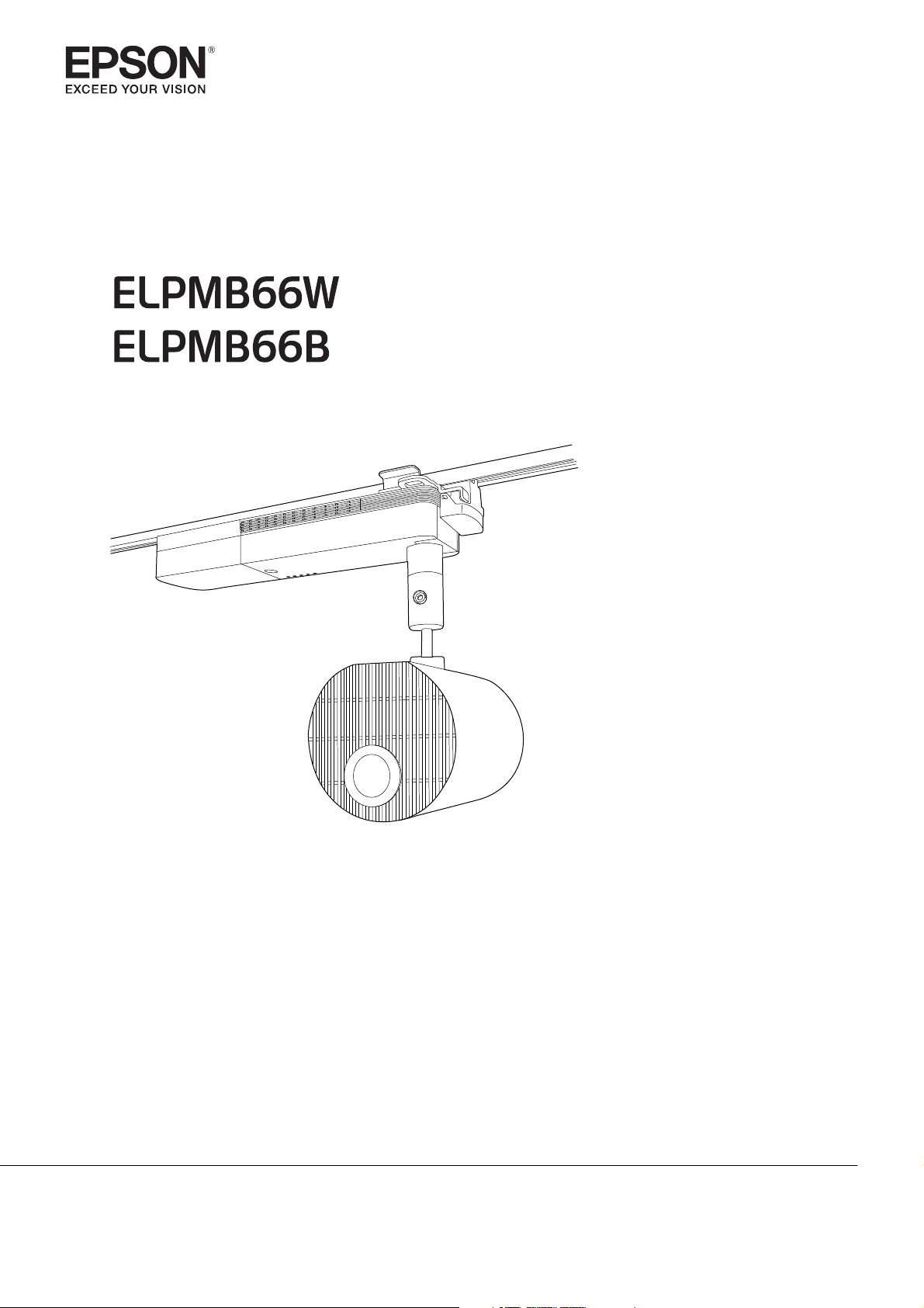
Installation Guide
Page 2
Using the Product Safely
Safety Instructions
This guide explains how to install the projector on a lighting track using the Lighting Track Mount.
Make sure you read this guide carefully to use the installation mounts and the projector safely. Incorrect
handling that ignores instructions in this guide could damage this product or could result in personal injury
or property damage. Keep this installation guide at hand for future reference.
Regarding how to handle the projector, read the User's Guide and Safety Instructions supplied with your
projector and follow the instructions in these documents.
Safety Indications
The documentation and this product use graphical symbols to show how to use this product safely and
correctly to prevent injury to customers and others, and damage to property.
The indications and their meaning are as follows. Make sure you understand them properly before reading
the guide.
Symbol Explanation
Warning
Caution
This symbol indicates information that, if ignored, could possibly result in personal injury or
even death due to incorrect handling.
This symbol indicates information that, if ignored, could possibly result in personal injury or
physical damage due to incorrect handling.
General Information Indications
Symbols Explanation
Symbol indicating an action that must not be done
Symbol indicating an action that should be done
Symbol indicating related or useful information
c
Precautions on Installing the Projector
Warning
Installing the lighting track as well as installing the projector on a lighting track should only
be performed by a professional with the necessary skills and know-how.
If installation work is not carried out correctly, the mount or the projector could fall causing injury
or accident to occur.
When installing, make sure you install bolts and screws specified in this guide and follow
the steps described in this guide.
If the instructions are not followed, the mount or the projector could fall causing injury or accident
to occur.
Installation should be performed by at least two people. Also, make sure you have a secure,
stable footing so that you do not drop the mount or the projector.
1
Page 3
Using the Product Safely
Warning
Make sure you turn off the lighting track before performing work.
If you perform work while the lighting track is turned on, an electric shock could occur.
Make sure you attach the safety wire supplied with the projector to prevent the mount
from falling due to earthquakes or vibrations.
Do not attach anything to this mount except for a projector from EPSON.
Otherwise, the mount may falls and could cause death or personal injury.
Note the following when handling the power cable. Otherwise, it could cause a fire or
electric shock.
•
Do not handle the plug with wet hands
•
Do not use a damaged or modified power cable
•
Do not apply excessive force to the power cable
•
Do not trap the cable between parts of the mount and so on during installation
When installing, do not pull or apply excessive force to the cable connected to the projector.
Do not wind cables around the projector or the mount.
When wiring cables and so on, route the cables so that it avoids the screws and bolts.
If the cables come into contact with screws or bolts, it could cause a fire or electric shock to occur.
Make sure you tighten the screws or bolts completely when installing.
If they are not tightened completely, the mount or the projector could fall causing injury or accident
to occur.
Never loosen the screws or bolts after installation.
Make sure that you check for any loose screws or bolts on a regular basis, and if any are loose,
tighten them completely. If they are not tightened completely, the mount or the projector could
fall causing injury or accident to occur.
When securing the mount, do not use adhesives to prevent the screws from loosening,
and do not use lubricants, oils, and so on.
If you use adhesives to prevent the screws from loosening, or if you use things such as lubricants
or oils, the mount or the projector case may crack causing an injury or an accident.
Do not hang from the mount or the projector, and do not place heavy objects on them.
Otherwise, the mount or the projector may fall and could cause death or injury.
Do not apply excessive force to the projector or the mount when installing.
Otherwise, the mount or the projector may be damaged and could cause death or injury.
Do not install in the following situations. Contact your local dealer or Epson Service Call
Center.
•
If the product has been dropped or damaged before or during installation
•
If the mount is abnormal or damaged
2
Page 4
Using the Product Safely
Warnings and Cautions on the Installation Locations
Warning
Make sure that the lighting track and ceiling are strong enough to support the mount and
the projector.
Make sure the lighting track is firmly secured as instructed in the user's guide supplied with
the lighting track.
Only install on lighting tracks that support installation for this mount.
Otherwise, the mount or the projector may fall and could cause death or injury.
Do not attach to the lighting track in the following ways.
Otherwise, the lighting track could be damaged. Also, the mount or projector may fall and cause
an injury or accident to occur.
•
Lighting tracks attached to walls, floors, or inclined locations
•
Lighting tracks attached to un-reinforced ceilings
Do not install or use the projector in locations where it could be exposed to rain or water,
such as outdoors, in baths or shower rooms.
Otherwise, it could cause a fire or electric shock.
Do not install in areas exposed to oily smoke or smoke from events.
Otherwise, it could cause a fire or electric shock.
Do not use the projector in a location subject to combustible or explosive gas.
If the inside of the projector gets too hot, it could ignite and cause a fire.
Do not cover the projector's air intake vent or air exhaust vent.
If either of the vents are covered, the projector's internal temperature could rise and cause a fire.
Caution
Do not install the projector in a location outside the projector's operating temperature
range.
Such an environment may damage the projector.
Install it away from air outlets such as air conditioners.
If the air from an air conditioner and so on flows directly over the projector, the temperature rises
and the projector may not operate correctly.
Install it away from fluorescent lights.
Some kinds of fluorescent lights could interfere with the remote control of the projector.
Install it in a location where strong light such as fluorescent light and direct sunlight does
not shine on the remote receiver.
If strong rays of light shine on the remote receiver, remote control operations may not be performed
correctly.
Make sure you install the projector in a location free from excessive dust and humidity to
prevent the lens or internal components from becoming dirty.
3
Page 5

Contents
Using the Product Safely
Safety Instructions .................... 1
Safety Indications .......................1
General Information Indications .............1
Precautions on Installing the Projector........1
Warnings and Cautions on the Installation
Locations ............................. 3
Preparing the Projector
Package Contents . . ................... 5
Mountable Lighting Tracks ............ 6
Installation Procedure
Preparing the Projector ............... 7
Attaching the Mount to the Projector
....................................... 9
Attaching the Rotating Unit ................9
Attaching the Plate Unit ..................10
Attaching the Projector to the Lighting
Track ............................... 12
Attaching the Stopper Unit ................12
Attaching the Plate Unit to the Stopper Unit
.................................... 14
Connecting Cables ................... 16
Installing the Safety Wire ............. 17
Appendix
Specification . . . . . ................... 19
Figures of Installation Dimensions ........... 20
4
Page 6
Preparing the Projector
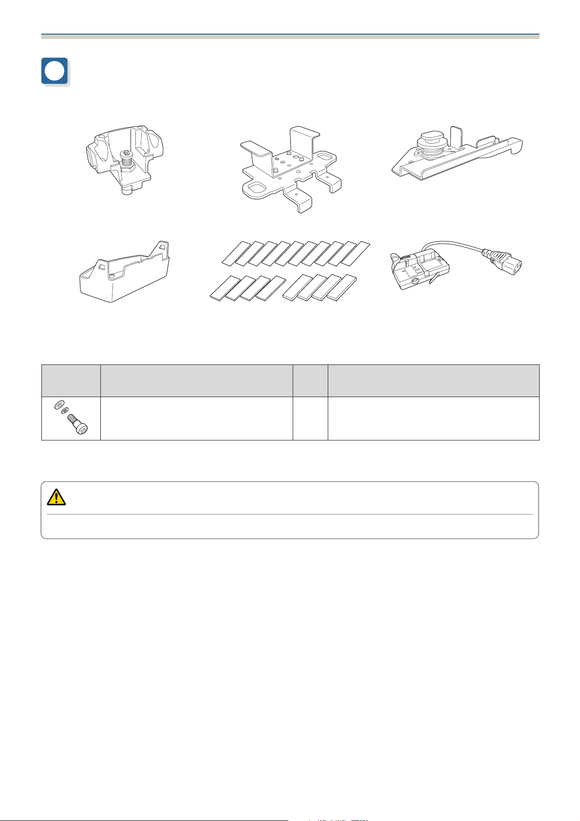
Package Contents
Check that you have all of the following accessories before you start work.
Stopper unit Plate unit Rotating unit
Stopper cover Spacers (0.8 mm) x10
Spacers (2 mm) x4
Spacers (5 mm) x4
Shape Name
Quan-
Application
tity
M4 x 10 mm cross recessed head screw
(with washer)
•
Make sure you use the bolts or screws supplied with this product to install mounts.
•
Gather the tools and parts you need before you begin installation.
10 Secures the mount.
Caution
Do not touch the sharp parts with unprotected hands as this could cause an injury.
Power adapter
5
Page 7
Preparing the Projector
Mountable Lighting Tracks
Check the model number of the lighting track you want to install on before performing installation.
You can attach the mount to the following types of lighting track.
The following information is current as of September 2020. Details are subject to change without notice.
When using outside Asia
Manufacturer Model Number
NORDIC ALUMINIUM
•
Global trac pro XTSF-4100-1
•
Global trac pro XTSF-4100-2
•
Global trac pro XTSF-4100-3
•
Global trac pro XTSF-4200-1
•
Global trac pro XTSF-4200-2
•
Global trac pro XTSF-4200-3
•
Global trac pro XTSF-4300-1
•
Global trac pro XTSF-4300-2
•
Global trac pro XTSF-4300-3
•
Global trac pro XTS-4100-1
•
Global trac pro XTS-4100-2
•
Global trac pro XTS-4100-3
•
Global trac pro XTS-4200-1
•
Global trac pro XTS-4200-2
•
Global trac pro XTS-4200-3
•
Global trac pro XTS-4300-1
•
Global trac pro XTS-4300-2
•
Global trac pro XTS-4300-3
When using inside Asia
Manufacturer Model Number
ERCO
EUTRAC Stromschienen
•
ERCO track 78301.000
•
ERCO track 78302.000
•
ERCO track 78303.000
•
ERCO track 78323.000
•
ERCO track 78341.000
•
ERCO track 78342.000
•
ERCO track 78343.000
•
ERCO track 78353.000
•
ERCO track 78361.000
•
ERCO track 78362.000
•
ERCO track 78363.000
•
ERCO track 79873.000
•
Surface Track Standard 25-102
•
Surface Track Standard 25-103
•
Surface Track Standard 25-106
6
Page 8
Installation Procedure
Preparing the Projector
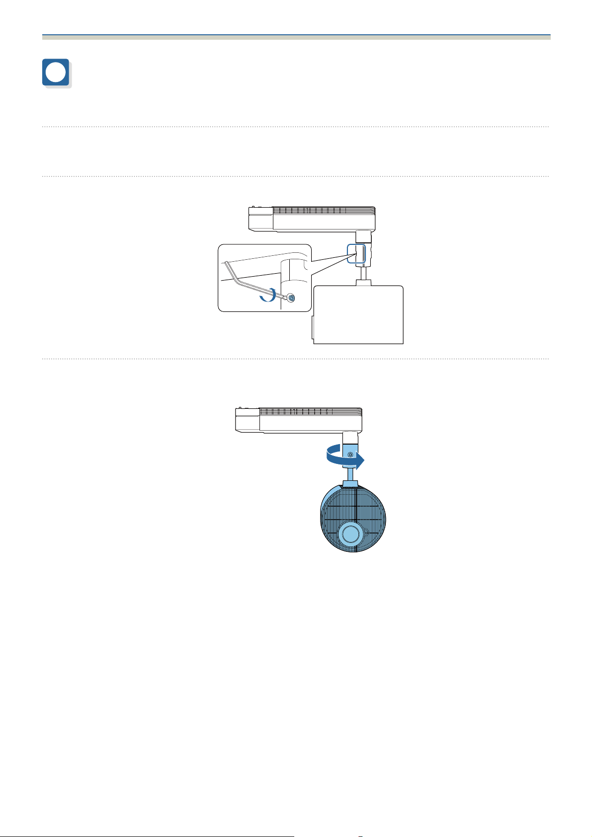
Adjust the orientation of the projector to make installing easier.
Place the projector on a flat surface on a soft cloth.
a
Loosen the screw for the ball joint with a hexagonal wrench supplied with the projector.
b
c
Change the projector's orientation.
You can change the orientation of the projector as shown below.
7
Page 9
Installation Procedure
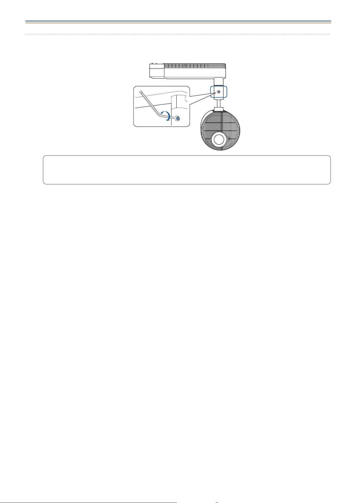
Tighten the screw for the ball joint with a hexagonal wrench to secure it in place.
d
Make sure you tighten the screw completely so that the ball joint does not move during installation.
When re-tightening with the hexagonal wrench supplied, do not use the ball point side of the
hexagonal wrench.
c
8
Page 10
Installation Procedure
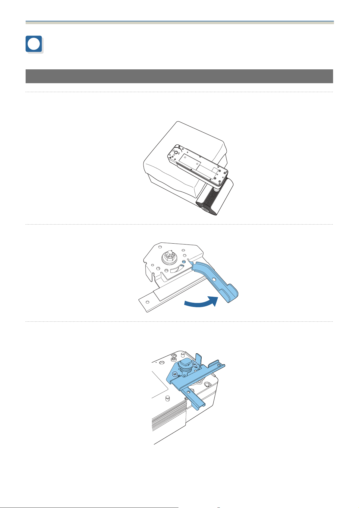
Attaching the Mount to the Projector
Attaching the Rotating Unit
Place the projector on your workbench.
a
b
Place the projector on a soft cloth on a workbench (330 mm high).
Rotate the lever 90 degrees counterclockwise.
c
Place the rotating unit on the projector.
Align the pins (2 points) on the projector with the holes on the rotating unit.
9
Page 11
Installation Procedure
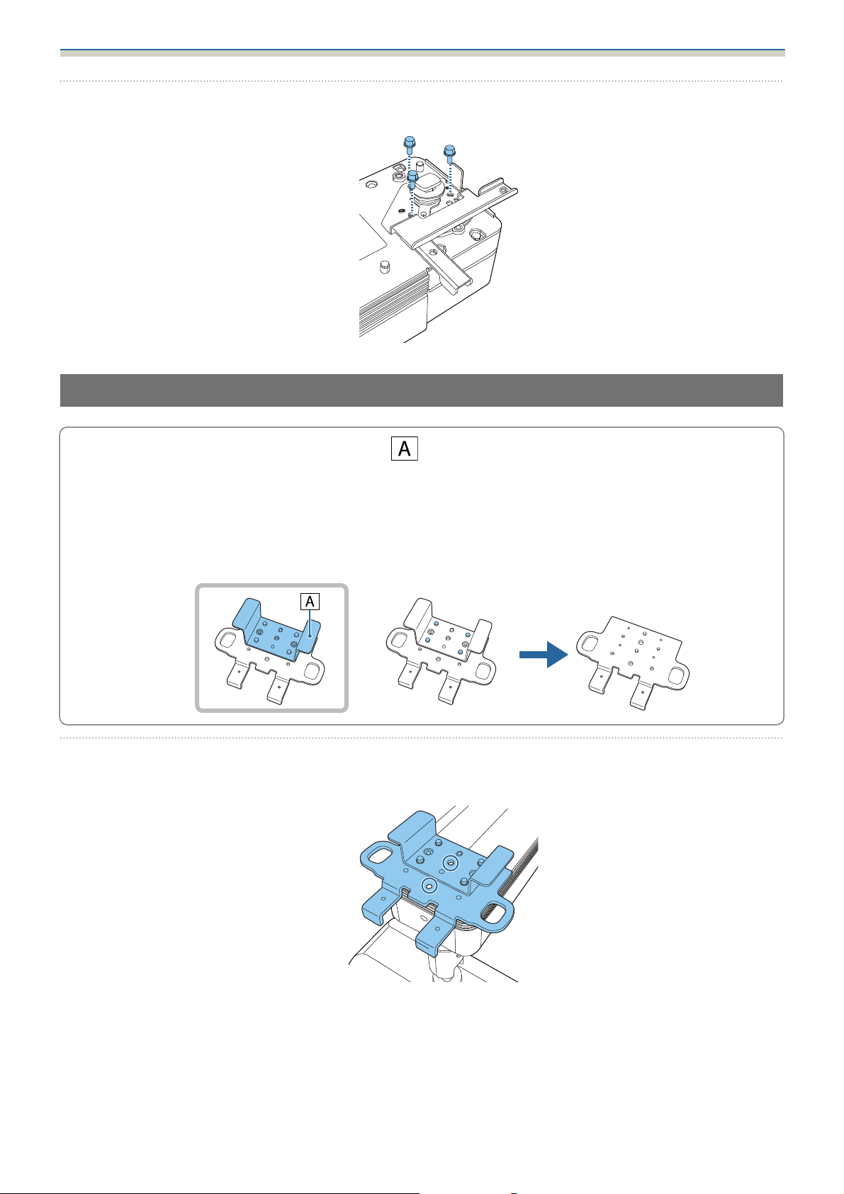
Secure the rotating unit to the projector using the M4 x 10 mm screws supplied (x3).
d
Attaching the Plate Unit
c
a
The plate unit includes a support bracket ( ) to prevent vibrations in the lighting track from being
transmitted to the projector.
Since the support bracket comes into direct contact with the ceiling, remove it in the following
situations.
•
If your ceiling is not strong enough
•
If you are installing on lighting tracks that are built-in to the ceiling
Place the plate unit on the projector.
Align the pins (2 points) on the projector with the holes on the plate unit.
10
Page 12
Installation Procedure
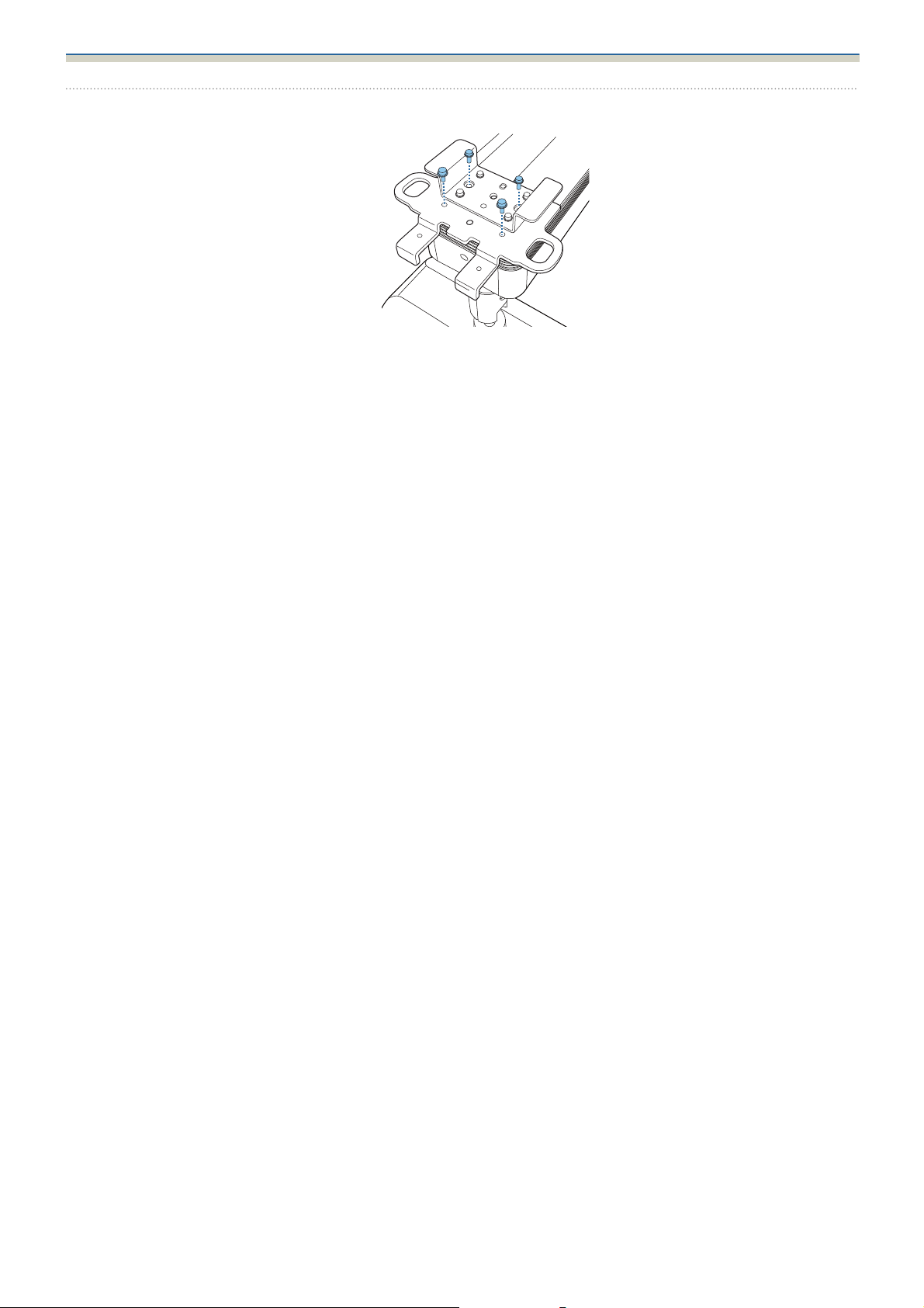
Secure the plate unit to the projector using the M4 x 10 mm screws supplied (x4).
b
11
Page 13
Installation Procedure
Attaching the Projector to the Lighting Track
Warning
•
Make sure you turn off the lighting track before performing installation work. Otherwise an electric shock
could occur.
•
Make sure the lighting track is firmly secured. Otherwise, the mount or projector may fall and cause an injury
or accident to occur.
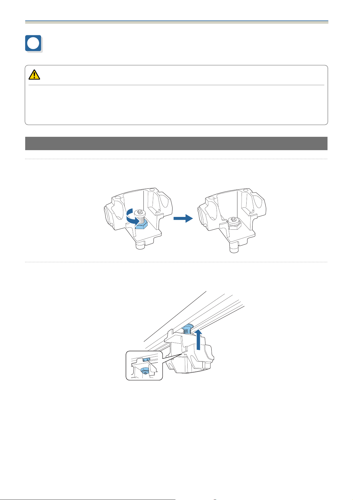
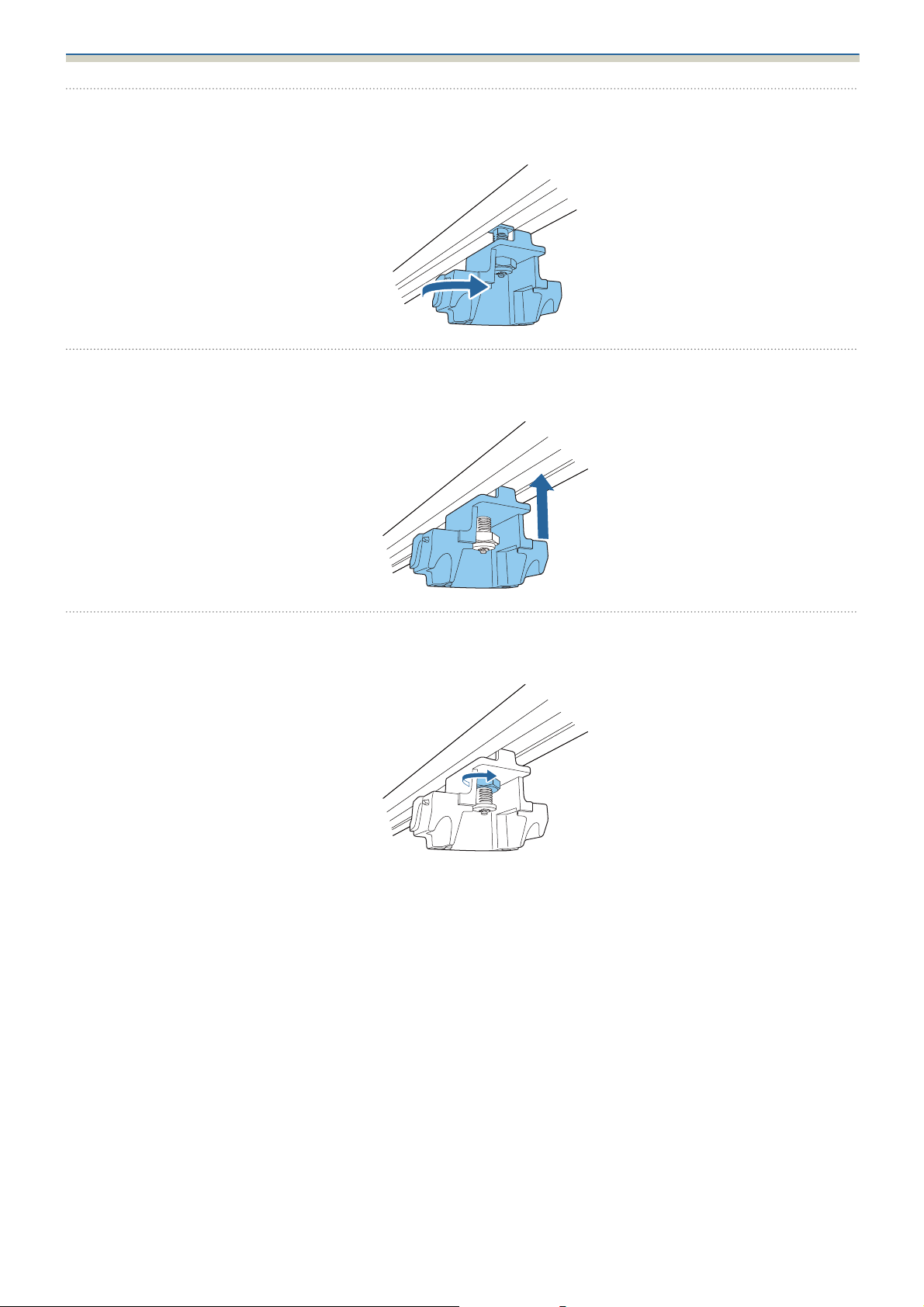
Attaching the Stopper Unit
Loosen the nut for the stopper unit.
a
b
Loosen until the nut reached the end of the rotating shaft.
Insert the rotating shaft of the stopper unit into the groove on the lighting track.
Push the rotating shaft up so that the tip of the shaft fits into the duct.
12
Page 14
Installation Procedure
Rotate the stopper unit 90 degrees.
c
d
The rotating shaft for the stopper unit fits into the groove on the lighting track.
Push up the stopper unit to insert the protruding section into the groove on the lighting
track.
e
Completely tighten the nut for the stopper unit to secure the lighting track and the stopper
unit.
13
Page 15
Installation Procedure
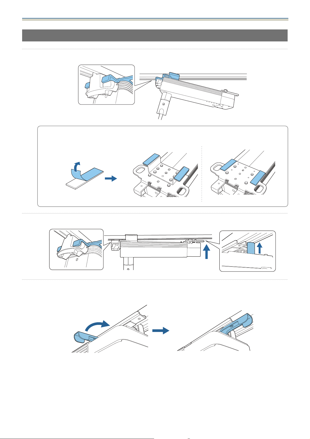
Attaching the Plate Unit to the Stopper Unit
Attach the hook on the plate unit to the stopper unit.
a
If there is a gap between the ceiling and the mount, attach the spacer supplied to the support
bracket or plate unit. If the gap is wide, insert multiple spacers.
c
b
c
Insert the protruding section on the rotating unit into the groove on the lighting track.
Rotate the lever of the rotating unit 90 degrees clockwise.
Rotate so that the screw hole positions overlap as shown in the following image.
14
Page 16
Installation Procedure
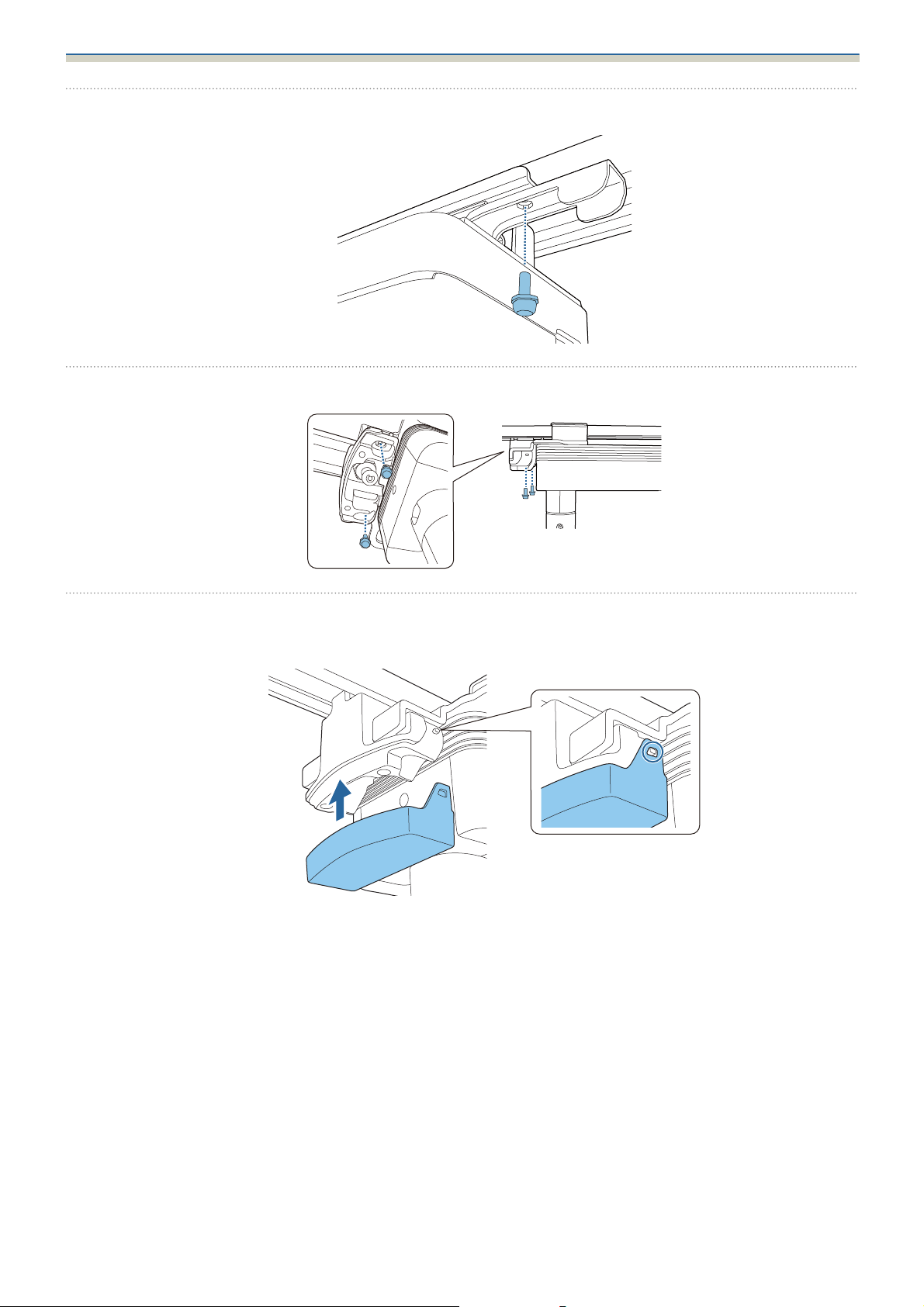
Secure the lever for the rotating unit with the M4 x 10 mm screw (x1) supplied.
d
Secure the plate unit to the stopper unit using the M4 x 10 mm screws supplied (x2).
e
f
Attach the stopper cover to the stopper unit.
Press in the stopper unit tabs until they snap into the stopper cover.
15
Page 17
Installation Procedure
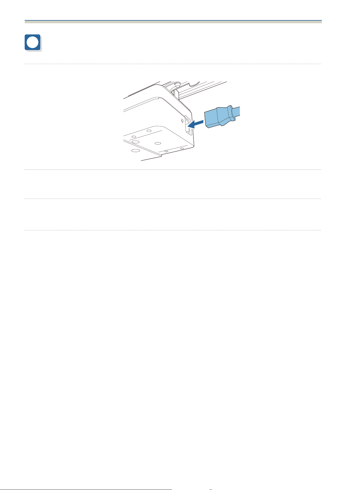
Connecting Cables
Connect the power adapter supplied to the projector's power inlet.
a
Connect the power adapter to the lighting track.
b
c
d
Connect the necessary cables and the SD card to the projector's interface.
Check the Projector's User's Guide for information on the connection ports.
Attach the power adapter cover to the projector.
16
Page 18
Installation Procedure
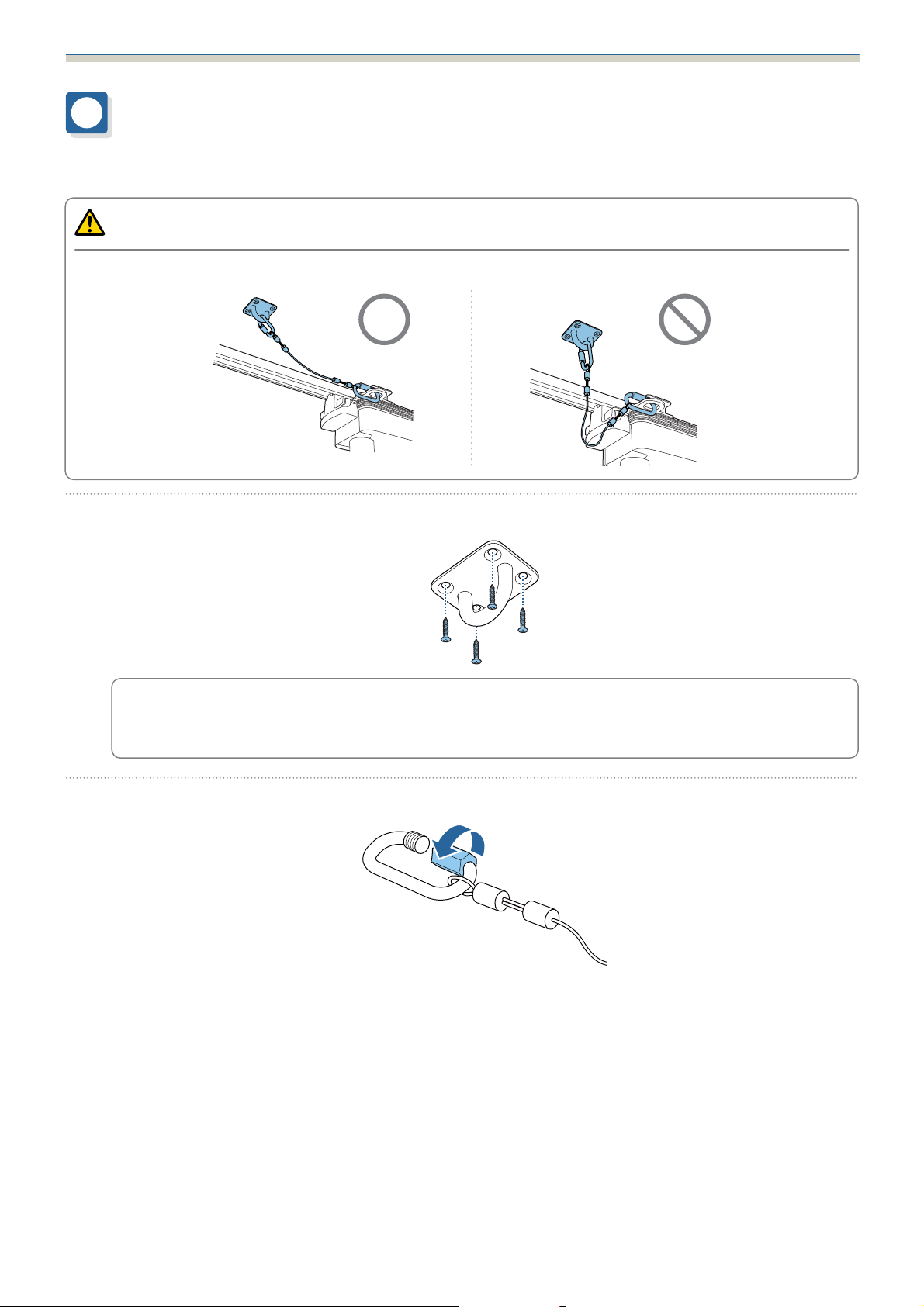
Installing the Safety Wire
Install the safety wire supplied to the projector to prevent the projector from falling.
Caution
Attach the wire so that there is as little slack as possible.
a
b
Attach the wire hook mount supplied with the projector to the ceiling.
•
When installing the wire hook mount, use commercially available wood screws with a nominal
c
Loosen the carabiner for the safety wire supplied with the projector.
diameter of 3.8 mm.
•
Make sure that the wood screws enter at least 20 mm into the ceiling's underlay.
17
Page 19
Installation Procedure
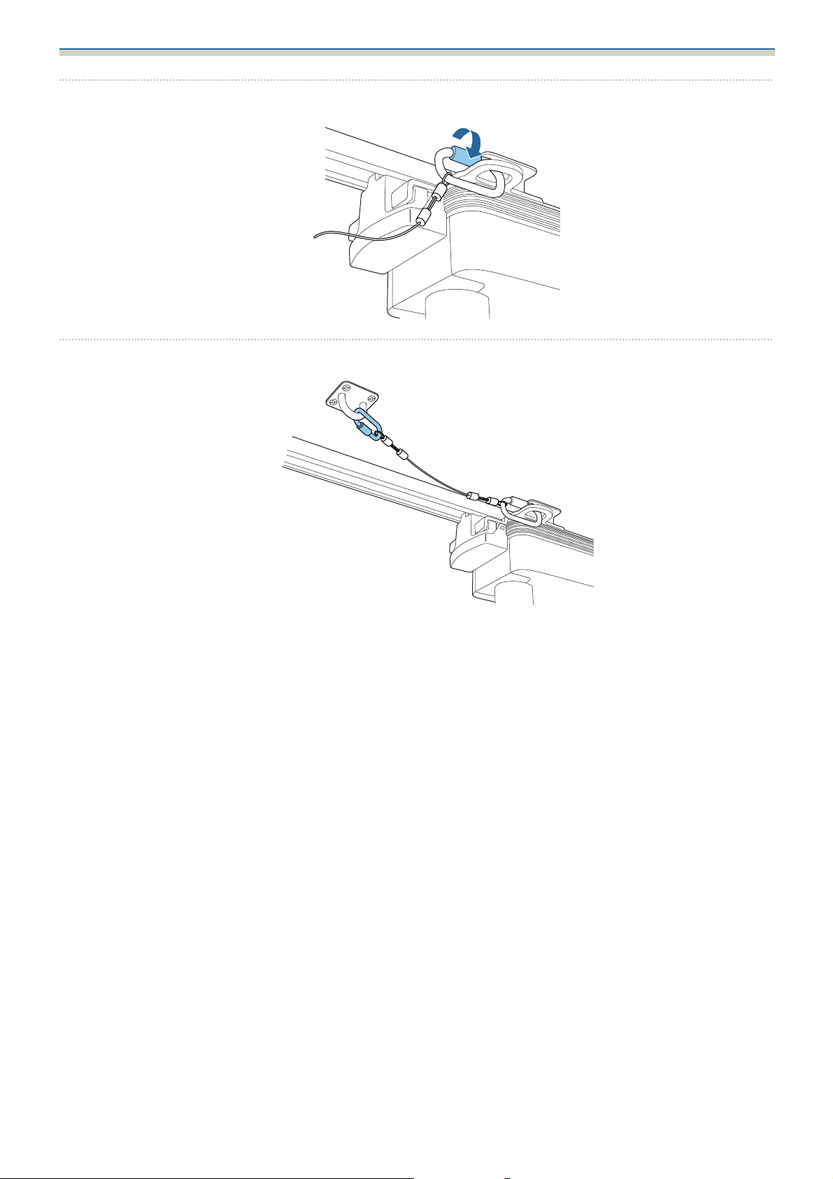
Insert the loosened carabiner through the hole in the plate unit, and then tighten it.
c
Attach the carabiner for the safety wire to the wire hook mount attached to the ceiling.
d
18
Page 20

Appendix
Specification
Item Specification
Weight (stopper unit, plate unit, rotating unit, stopper
cover)
Exterior color ELPMB66W: White
Approx. 0.7 kg
ELPMB66B: Black
19
Page 21
Appendix
Figures of Installation Dimensions
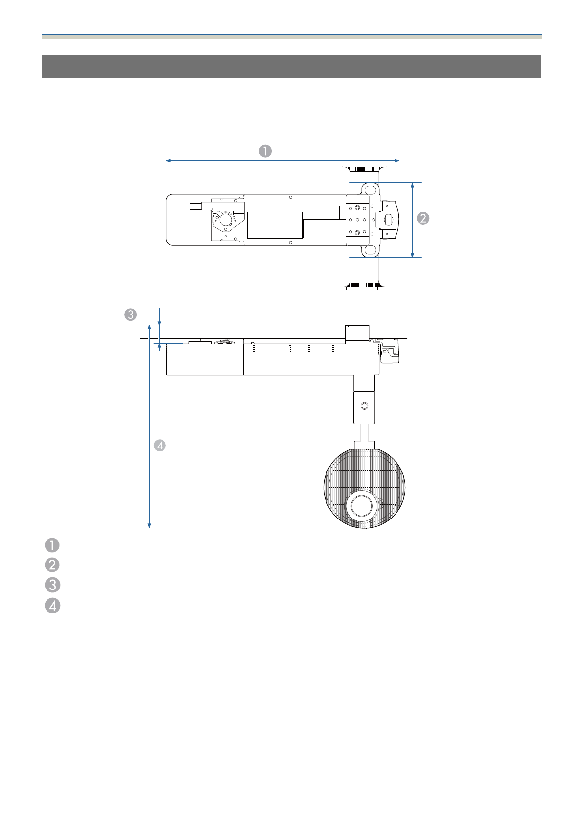
The following provides the dimensions for the EV-115/110.
When using outside Asia
501.6
[Unit: mm]
160.5
45.8
440.3
Width of top of projector
Vertical width of top of projector
Height from ceiling to top of projector
Height from ceiling to bottom of projector
20
Page 22
Appendix
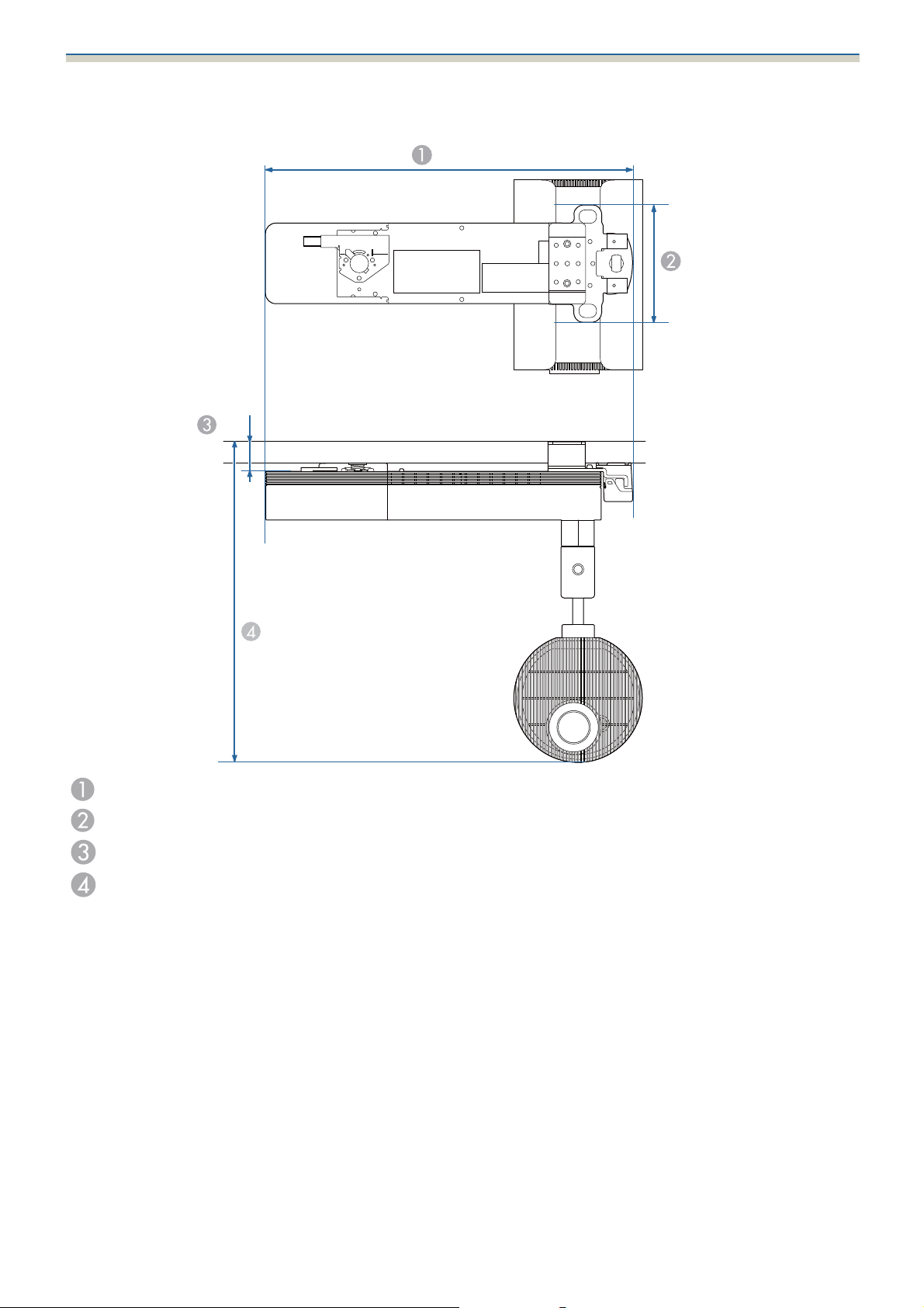
When using inside Asia
45.7
[Unit: mm]
501.6
160.5
440.2
Width of top of projector
Vertical width of top of projector
Height from ceiling to top of projector
Height from ceiling to bottom of projector
© 2020 Seiko Epson Corporation
2020.09 414025100EN
21
 Loading...