

Page 1
ELPMB24
Short Throw Projector Wall Mount Installation Manual
Manuel d'installation du kit de montage mural du projecteur à courte distance de projection
Installationsanleitung für Projektorwandhalterung für kurze Projektionsabstände
Manuale di installazione della staffa da parete per proiettore a focale corta
Manual de instalación del soporte de pared para proyectores con enfoque corto
Page 2
Safety Instructions
For your safety, read the all instructions in this manual before using the wall mount. Incorrect handling that ignores
instructions in this manual could damage the mount or could result in personal injury or property damage. Keep this
installation manual at hand for later reference.
Read User's Guide and Safety Instructions of your projector and follow the instructions in these documents.
Explanation of Symbols
The warning marks shown below are used throughout this installation manual to prevent personal injury or property damage.
Make sure you understand these warnings when reading this installation manual.
Warning
Caution
This symbol indicates information that, if ignored, could possibly result in personal injury or even death due to
incorrect handling.
This symbol indicates information that, if ignored, could possibly result in personal injury or physical damage due to
incorrect handling.
Symbol indicating an action that must not be done
Symbol indicating an action that should be done
Safety Precautions for Installation
Warning
The mount mass is approximately 10 kg (22 lb). Handle the mount carefully when transporting or carrying to prevent
injury.
The installation work should be performed by specialists who have special technical knowledge and ability. Incomplete
or incorrect installation could cause the mount to fall and cause personal injury or property damage. Contact the
customer support office listed on Epson Projector Contact List in the User's Guide of your projector when installing the
mount.
Turn off the projector when installing the mount.
Working with the projector turned on could cause fire or electric shock.
Handle the power cable carefully.
Incorrect handling could cause fire or electric shock. Observe the following precautions when handling:
• Do not handle the plug with wet hands.
• Do not use a power cable that is damaged or modified.
• Do not pull the power cable with too much force when routing the cable through the arm unit.
Do not put any thing heavier than the projector on the arm unit.
Doing so could cause the arm unit to fall and cause personal injury or property damage.
When you set the projector on a wall with this mount, the wall requires enough strength to hold the projector and this
mount. A wall of reinforced concrete or steel skeleton construction is recommended. Confirm the mass of the projector
and the mount, and keep the strength of the wall. If the wall does not have enough strength, reinforce the wall before
installing.
Do not install the mount in places where it might be subjected to vibration or shock.
Vibration or shock could cause damage to the projector or mounting surface. It could also cause the mount or the projector to fall and
cause personal injury or property damage.
Install the mount firmly to hold the mass of the projector and the mount, and to resist horizontal vibration. Use M8 nuts
and bolts.
Nuts and bolts smaller than M8 could cause the mount to fall. Epson takes no responsibility for any damage or injury caused by
incorrect installing.
The installation work should be performed by at least two qualified service personnel. If you need to loosen any screws
while installing, be careful not to drop the mount.
If the mount or the projector falls down, it could cause personal injury or property damage.
2
Page 3
Warning
Do not use the mount when damaged.
Doing so could cause the arm unit to fall and cause personal injury or property damage.
Never modify the mount.
Do not hang onto the mount. Or do not hang a heavy object on the mount.
It is dangerous if the mount falls down. If the projector or the arm unit falls down, it could cause personal injury or property damage.
Stop using this mount and contact the customer support office listed on Epson Projector Contact List in the User's Guide
of your projector when the following trouble occurs.
• The mount is dropped and/or damaged during installation.
• The arm is about to fall.
If you use adhesives to prevent the screws from loosening or things such as lubricants or oils on the mount, the case may
crack and this could cause the projector to fall. It could cause personal injury or property damage. Do not use adhesives,
lubricants or oils to install or adjust the mount.
Tighten all screws firmly after adjustment.
If the screws are not properly tightened, it could cause the projector to fall and cause personal injury or property damage.
Never loosen the bolts and nuts after installation. Confirm that the screws have not become loosened on a regular basis.
If you find any loose, tighten the screws firmly.
If the screws are not properly tightened, it could cause the projector to fall and cause personal injury or property damage.
Caution
Do not use in places where the humidity is high.
High humidity could cause fire or electric shock.
English
Do not install at place where there is a lot of dust, or a place where it may come into contact with smoke or steam such as
near cooking appliances or a humidifier.
These could cause fire or electric shock.
Do not change the angle of this mount or the projector with excess force.
Too much force could damage the mount and could cause personal injury or property damage.
Before Usage
This product is for mounting an Epson Multimedia Projector on a wall.
Features
This mount is for short throw projector EB-410W/PowerLite 410W.
Place to Install the Mount
Perform the power engineering work in advance to the place where the mount is installed.
Do not install the mount in places where it might be subjected to vibration or shock. It could cause damage to the projector
or mounting surface. It could also cause this mount or the projector to fall and cause serious injury or even death.
Install the projector at a place away from other electric devices such as fluorescent lights or air conditioning. Some kinds of
fluorescent lights could interfere with the remote control of the projector.
It is recommended to keep connection cable length less than 20 meters to reduce the external noise.
Install the mount in place where there is less dust and humidity to prevent the lens or optical components from becoming
dirty.
Do not install the mount at a place where the operating temperature for your projector might be exceeded. This type of
environment could damage the projector.
3
Page 4

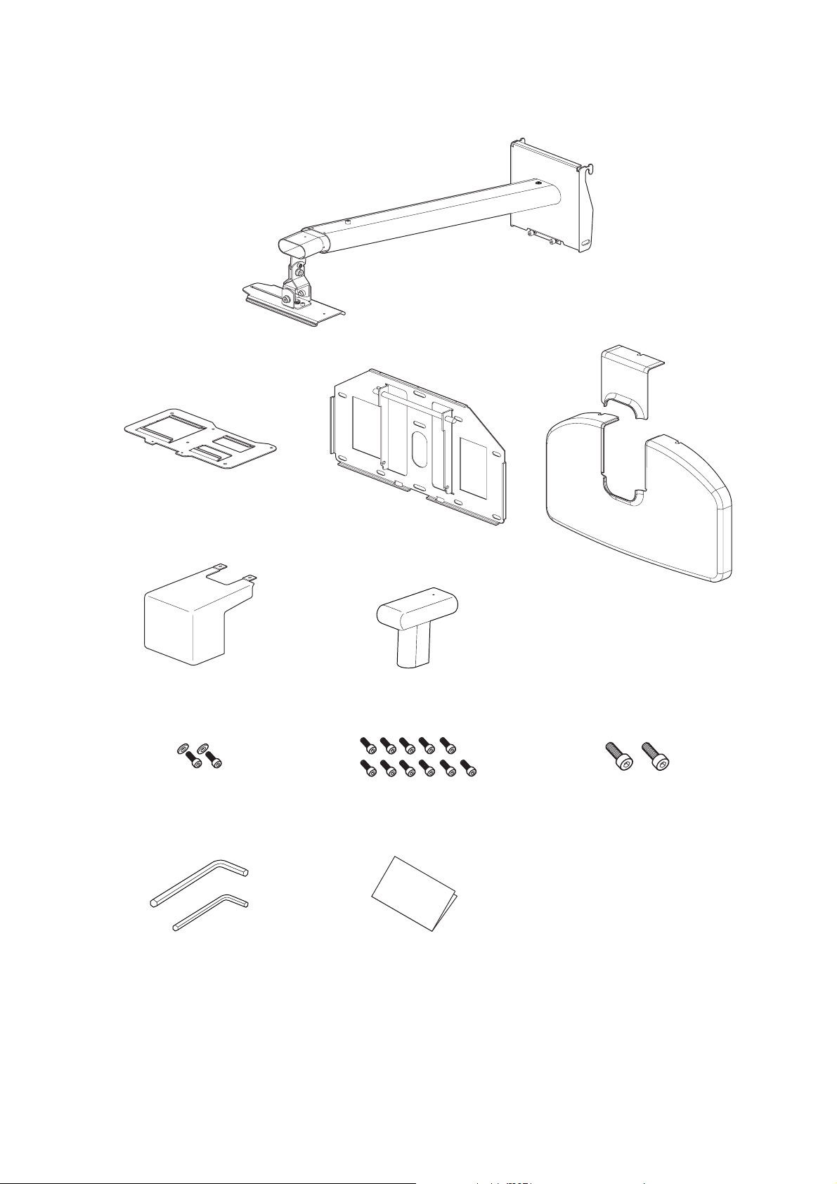
Package Contents
Projector plate
ELPMB24 Wall Mount
Cable cover
M4 × 12 mm hexagon socket head
cap bolt
with washers (2 pcs.)
Hexagon wrench (M4, M8)
Wall plate
Arm cover
M4 × 12 mm hexagon socket head
cap bolt
without washers (11 pcs.)
Installation manual
(this manual)
Wall plate cover
M8 × 16 mm hexagon socket head
cap bolt
without washers (2 pcs.)
Use the bolts supplied with this mount to install it, as directed in this manual. Do not substitute these bolts with any other
types. In addition, you need to use M8 × 50 mm anchors (at least 3 pcs.) and 8 × 80 mm lag bolts (at least 3 pcs.) that are
available at the store to attach the wall plate to the wall.
Gather the tools and parts you need before you begin installation.
4
Page 5
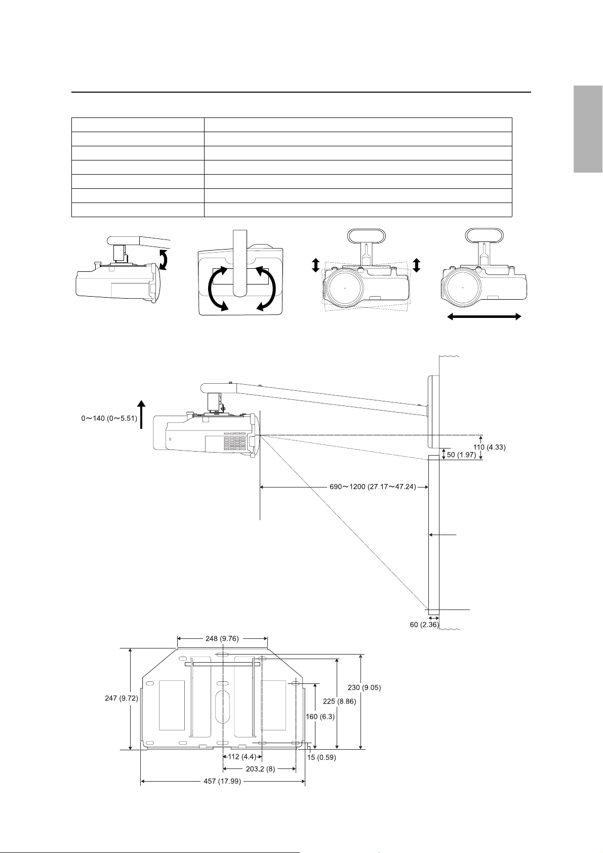
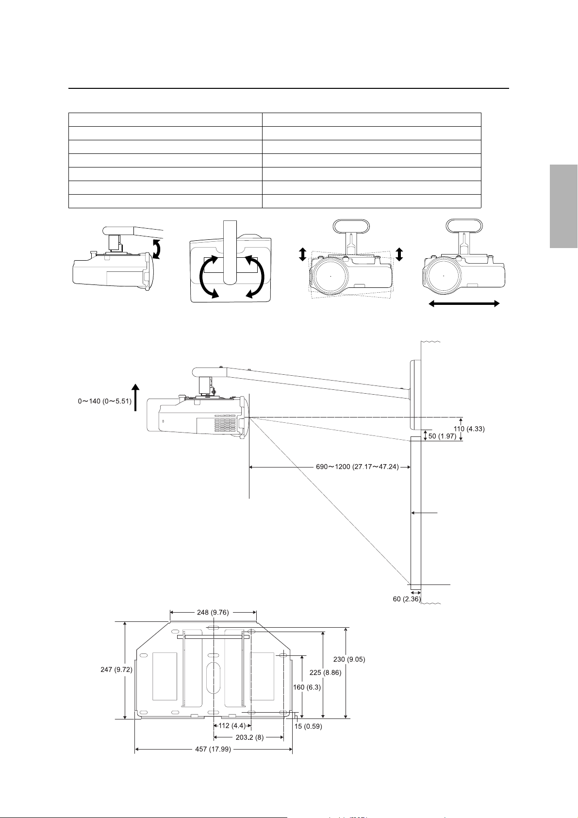
Specifications
Mass Approx. 10 kg (22 lb)
Arm length Approx. 1240 mm (48.8 in.) (maximum)
Vertical slide adjustment range 0 to 140 mm (5.5 in.)
Vertical tilt adjustment range 0 to ± 7°
Horizontal rotation adjustment range 0 to ± 5°
Horizontal roll adjustment range 0 to ± 5°
Horizontal slide adjustment range 0 to ± 45 mm (1.8 in.)
English
Vertical tilt adjustment
Vertical slide
adjustment
Horizontal rotation adjustment
Horizontal roll adjustment
Horizontal slide adjustment
Center of
the lens
Projection surface
Units: mm (inches)
5
Page 6

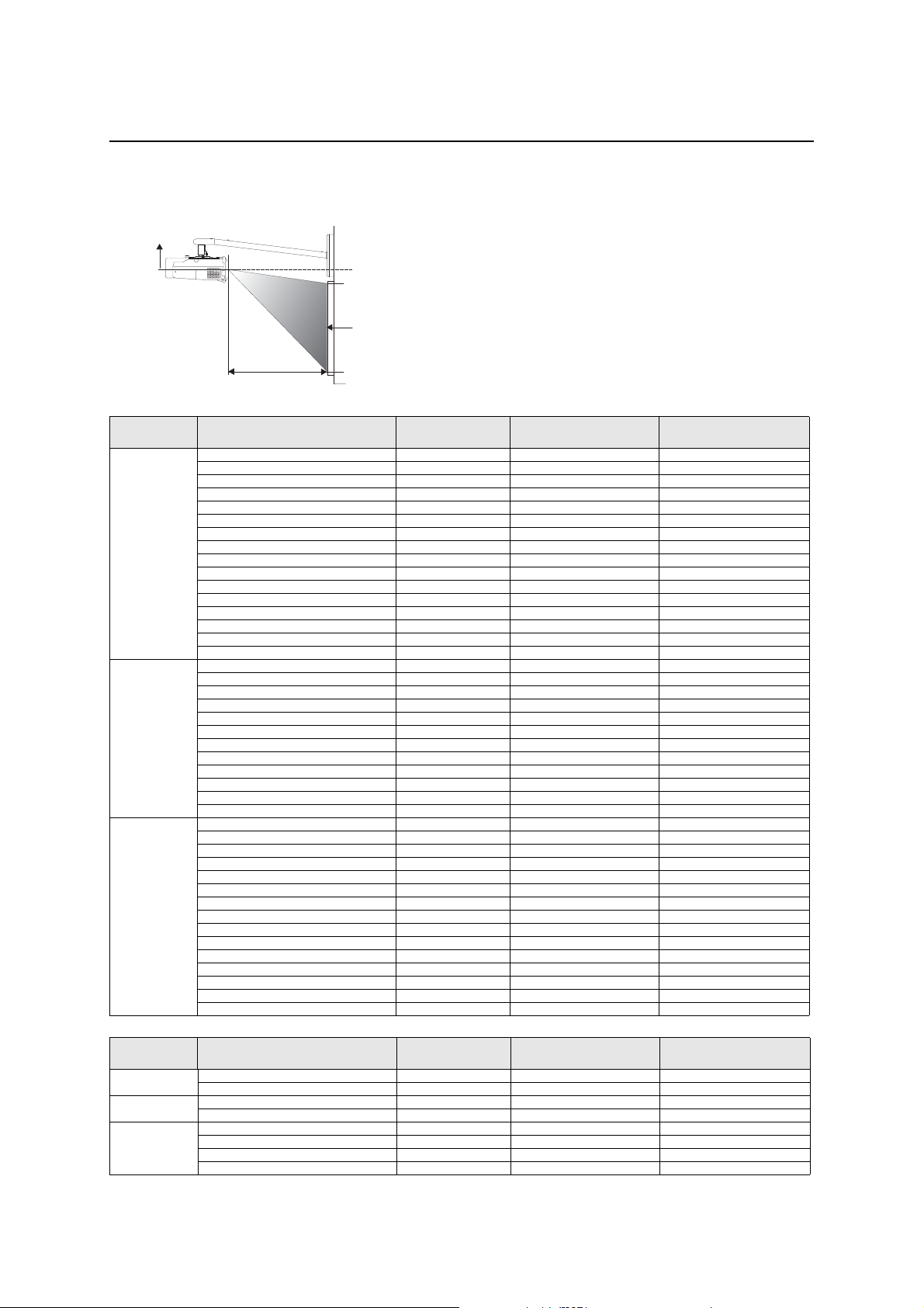
Screen Size and Projection Distance
Refer to the table below and install the mount and projector to project images with appropriate size. The value is only as a guide.
The recommended projection distance is 69 to 119 cm (27 to 47 in.).
B
Center of the lens
Projection surface
A
Aspect ratio Interactive whiteboard * Screen size Projection distance (A)
Vertical slide adjustment (B)
Minimum (Wide)
4:3 59" (min.) 69 (27.17) 0
16:10 67" (min.) 69 (27.17) 0
16:9 65" (min.) 69 (27.17) 4 (1.57)
Hitachi Cambridge Board 60 60" 70 (27.56) 0
Hitachi StarBoard FX-63 63" 74 (29.13) 0
Promethean Activboard 64 64" 75 (29.53) 0
70" 82 (32.28) 0
SMART Board 680 77" 91 (35.83) 0
Hitachi Cambridge Board 77 77" 91 (35.83) 0
Hitachi StarBoard FX-77 77" 91 (35.83) 0
RM ClassBoard 77.5 77.5" 91 (35.83) 0
Promethean Activboard 78 78" 92 (36.22) 0
PolyVision TS610 78" 92 (36.22) 0
80" 94 (37.01) 0
85" 100 (39.37) 0
90" 107 (42.13) 0
95" 113 (44.49) 0
100" (max.) 119 (46.85) 0
70" 72 (28.35) 0
75" 78 (30.71) 0
PolyVision TS610 78" 81 (31.89) 0
80" 83 (32.68) 0
85" 88 (34.65) 0
90" 94 (37.01) 0
95" 99 (38.98) 0
100" 105 (41.34) 0
105" 110 (43.31) 0
110" 115 (45.28) 0
113" (max.) 119 (46.85) 0
70" 74 (29.13) 5 (1.97)
Interwrite 1071 71" 75 (29.53) 5 (1.97)
75" 80 (31.50) 5 (1.97)
Interwrite 1070 77" 82 (32.28) 5 (1.97)
80" 85 (33.46) 6 (2.36)
Hitachi StarBoard FX-82Wide 82" 88 (34.65) 6 (2.36)
Interwrite 1085 85" 91 (35.83) 6 (2.36)
90" 96 (37.80) 6 (2.36)
SMART Board 690 94" 101 (39.76) 7 (2.76)
Promethean Activboard 95 95" 102 (40.16) 7 (2.76)
100" 108 (42.52) 7 (2.76)
PolyVision TS810 104" 112 (44.09) 7 (2.76)
105" 113 (44.49) 7 (2.76)
110" (max.) 119 (46.85) 7 (2.76)
Units: cm (inches)
Aspect ratio Interactive whiteboard * Screen size Projection distance (A)
Vertical slide adjustment (B)
Maximum (Tele)
4:3 PolyVision TS410 44" 69 (27.17) 11 (4.33)
16:10 50" 69 (27.17) 11 (4.33)
16:9 48" 69 (27.17) 14 (5.51)
RM ClassBoard 60 60" 87 (34.25) 15 (5.91)**
Interwrite 1060 60" 87 (34.25) 15 (5.91)**
74" 119 (46.85) 11 (4.33)
84" 119 (46.85) 11 (4.33)
82" 119 (46.85) 17 (6.69)**
* Product names are the trademarks or registered trademarks of their respective owners.
** Allow at least 6 cm (2.4 in.) space between the top of the whiteboard and the bottom of the wall plate.
6
Page 7
Assembly and Installation
Make sure to follow the steps below to install the mount. If you ignore these steps, the mount could fall down and could cause
personal injury or property damage.
The combined mass of this mount and the projector is approximately 14 kg (31 lb) at maximum. Before starting
the installation, carefully check the construction, material, and strength of the wall and use the most appropriate
methods to install.
1. Installing the wall plate to the wall
Attach the wall plate to the wall using M8 × 50 mm anchor (more than 3 pcs.) or 8 × 80 mm lag bolt (more than 3 pcs.).
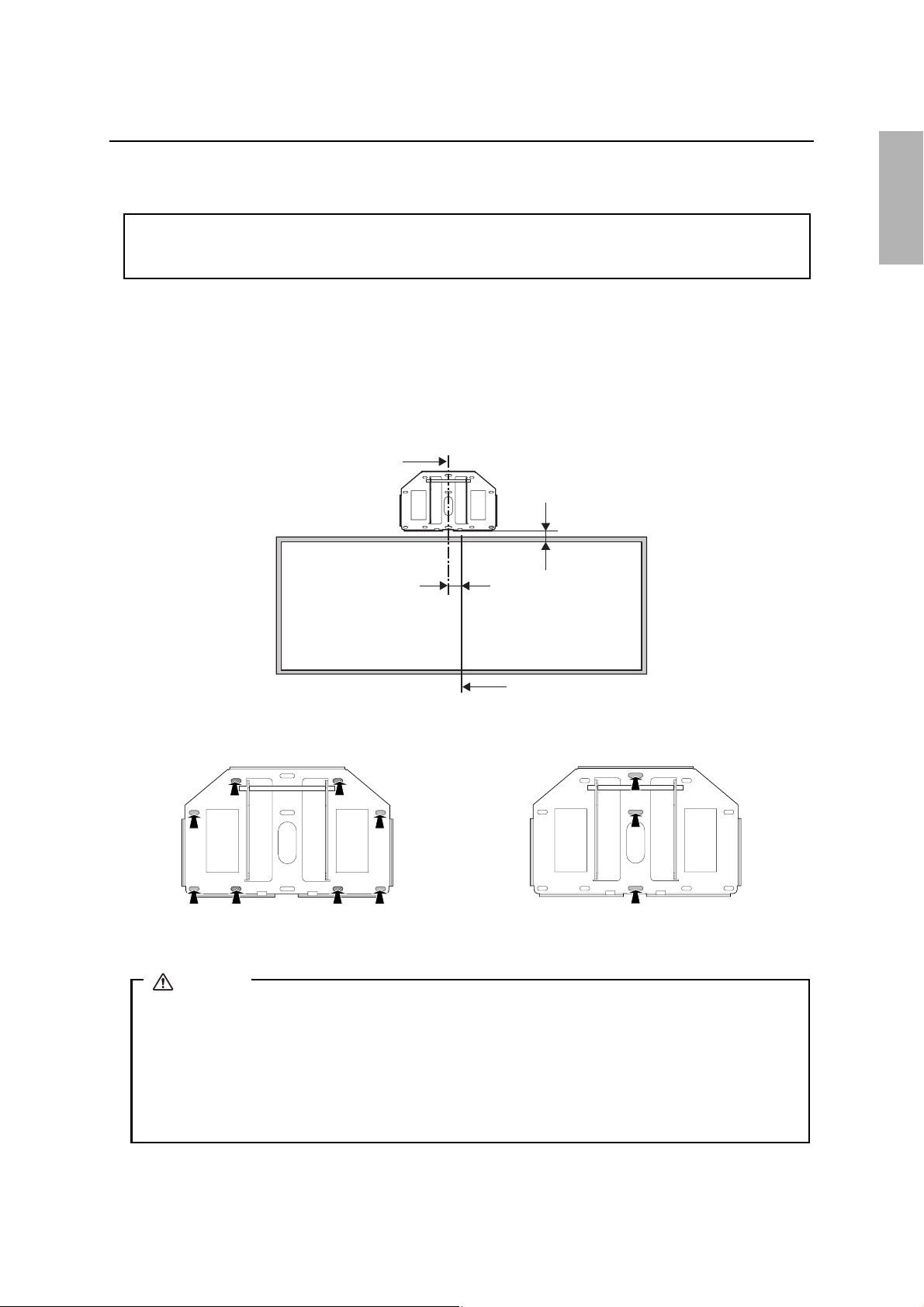
Set the horizontal center of the wall plate 8 cm (3.1 in.) left from the horizontal center of the whiteboard. See the
illustration below. Allow at least 6 cm (2.4 in.) space between the top of the whiteboard and the bottom of the wall plate. If
the 16:9 of maximum distance (tele) screen size is used, refer to the table in the previous page.
You can slide projector horizontally 4.5 cm (1.8 in.) after installing. See step 7 on page 10 for details.
Horizontal center of the wall plate
5 cm (2.0 in.)
8 cm (3.1 in.)
English
Horizontal center of the whiteboard
Insert the anchor or lag bolt into the place as shown below. Insert the anchors or lag bolts at least three points.
If you insert at four points, use four point As or four point Bs as shown below.
A
A
B
B
A
B
A
B
Four points mounting
Warning
❏ When you set the projector on the wall with this mount, the wall requires enough strength to hold the
projector and this mount. A wall of reinforced concrete or steel skeleton construction is recommended.
Confirm the mass of the projector and the mount, and keep the strength of the wall. If the wall does not
have enough strength, reinforce the wall before installing.
❏ Install the mount firmly to hold the mass of the projector and the mount, and to resist horizontal vibration.
Use M8 nuts and bolts. Nuts and bolts smaller than M8 could cause the mount to fall.
❏ Epson takes no responsibility for any damage or injury caused by incorrect installing.
A
A
A
A
B
B
B
B
Three points mounting
7
Page 8
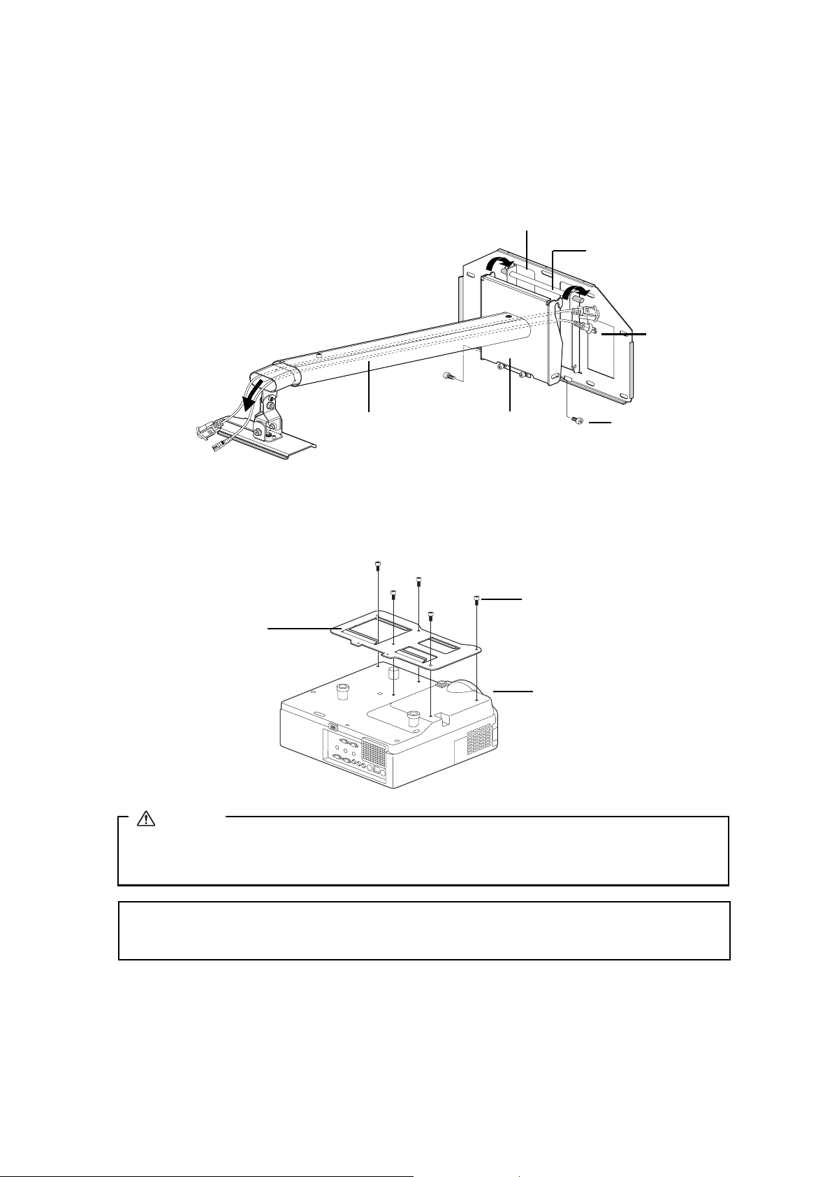
2. Attaching the arm unit to the wall plate
1) Route the cables through the arm unit as shown below.
2) Attach the hook on the arm plate to the bar on the wall plate.
Be careful not to pinch cables between the arm plate and the wall plate.
3) Secure the arm plate temporarily using two M8
× 16 mm hexagon socket head cap bolts.
Wall plate
Bar of the wall plate
Power cable
Arm unit
Arm plate
M8 × 16 mm hexagon
socket head cap bolt
(2 pcs.)
3. Attaching the projector plate to the projector
1) Place the projector upside down.
2) Attach the projector plate to the projector using the hexagon wrench (M4) and five M4 × 12 mm bolts.
M4 × 12 mm hexagon socket head
cap bolt (5 pcs.)
Projector plate
Projector lens side
Warning
If you use adhesives to prevent the screws from loosening or things such as lubricants or oils on the mount, the
case may crack and this could cause the projector to fall. It could cause personal injury or property damage. Do
not use adhesives, lubricants or oils to install or adjust the mount.
q
Tighten the screws f i rmly.
8
Page 9
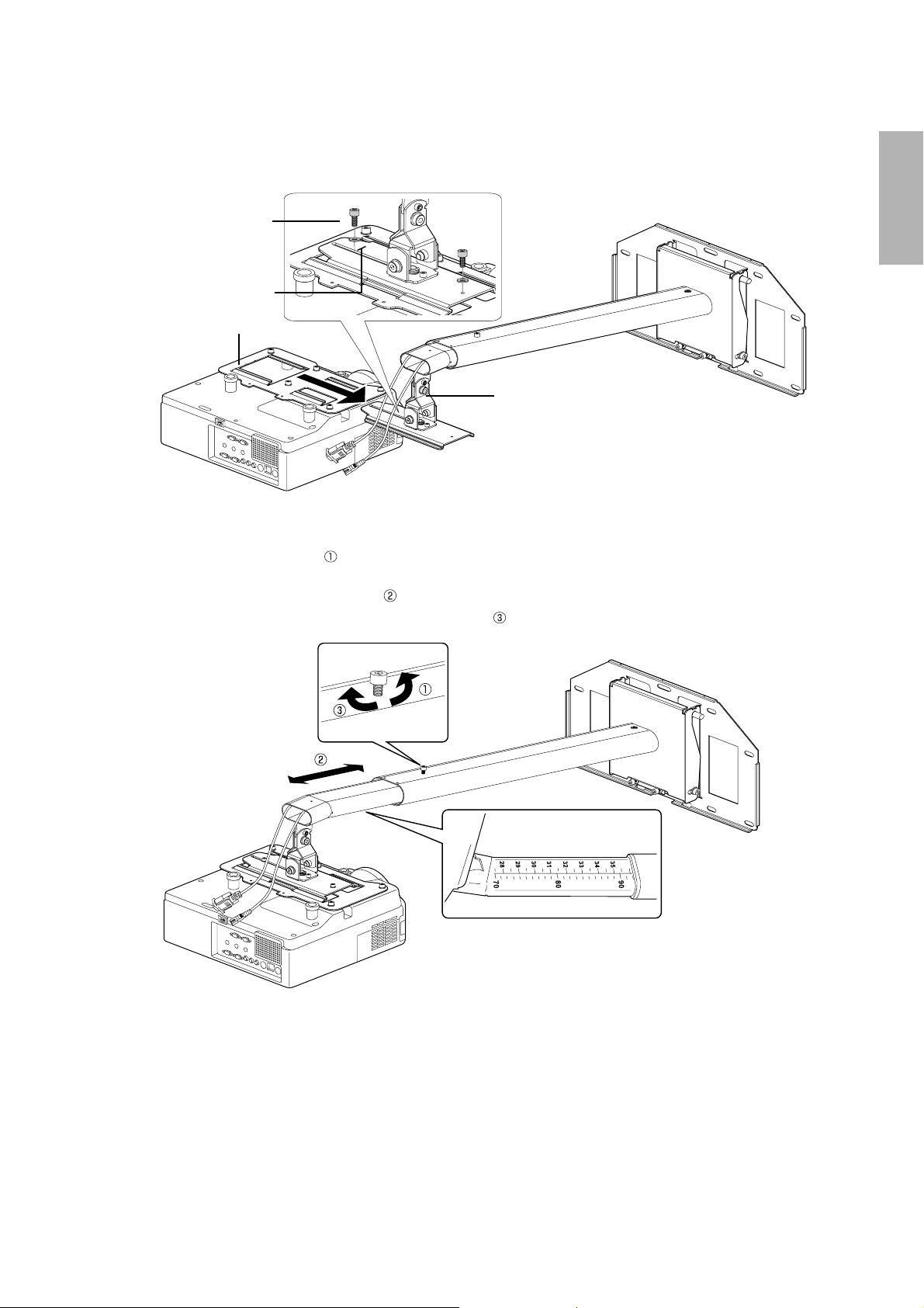
4. Installing the projector on the wall mount
1) Slide the projector plate onto the adjustment unit as shown below.
2) Secure the projector temporarily using two M4
× 12 mm bolts as shown below.
M4 × 12 mm hexagon socket
head cap bolt (2 pcs)
washer (2 pcs.)
Mark
Projector plate
Adjustment unit
5. Adjusting the length of the arm
1) Loosen the screw on the arm. ( )
2) Adjust the length of the arm using the measure on the bottom to match the projection distance recommended in "Screen
Size and Projection Distance" on page 6. ( )
3) Secure the arm position temporarily using the screw on top. ( )
English
6. Connecting the power cable and other cables to the projector
9
Page 10
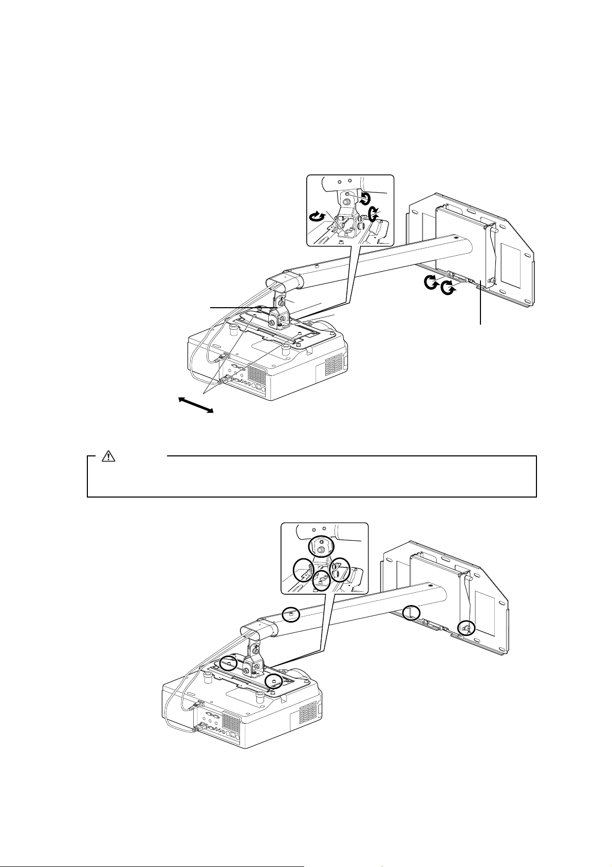
7. Turning on the projector and checking the screen
1) Loosen the screws on the adjustment unit (A, B, C, and D) as shown below to adjust the screen position.
2) If you project a 16:9 image at the minimum or maximum distance for your screen size, adjust the vertical slide (arm
angle) using two screws (E) on the bottom of the arm plate. The arm goes up when tighten the screws and goes down
when you loosen them.
Screw A: Vertical tilt adjustment: 0 to ± 7°
Screw B: Horizontal roll adjustment: 0 to ± 5°
Screw C: Horizontal rotation adjustment: 0 to ± 5°
Screw D: Horizontal slide adjustment: 0 to ± 45 mm (1.8 in.)
Screw E: Vertical slide adjustment: 0 to 140 mm (5.5 in.)
C
A
B
E
Arm plate
Adjustment unit
D
B
A
C
3) Firmly tighten the screws on the arm plate and adjustment unit using the hexagon wrench (M4 and M8).
Warning
Tighten all screws firmly. If the screws are not tightened firmly, it could cause the projector to fall and cause
personal injury or property damage.
10
Tighten the circled screws.
Page 11
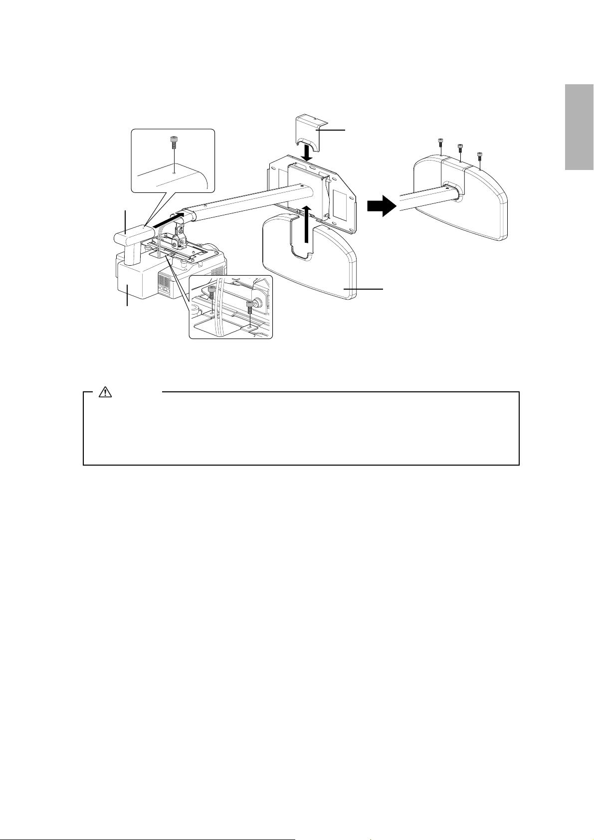
8. Attaching the protective covers
Attach the wall plate cover, cable cover, and arm cover using the hexagon wrench (M4) and six M4 × 12 mm bolts.
Wall plate cover
Arm cover
Wall plate cover
Cable cover
Only a specialist should remove or install the projector, including for maintenance and repairs. See User's Guide of your
projector for instructions on maintenance and repairs.
English
Warning
❏ Never loosen the bolts and nuts after installation. Confirm that the screws have not become loosened on a
regular basis. If you find any loose, tighten the screws firmly. If the screws are not tightened firmly, it could
cause the projector to fall and cause personal injury or property damage.
❏ Do not hang onto the mount. Or do not hang a heavy object on the mount. It is dangerous if the mount falls
down. If the projector or the arm unit falls down, it could cause personal injury or property damage.
11
Page 12
Consignes de sécurité
Pour votre sécurité, veuillez lire toutes les consignes contenues dans ce manuel avant d'utiliser le kit de montage mural. Une
manipulation incorrecte ne respectant pas ces consignes pourrait endommager le kit de montage ou provoquer des blessures
corporelles ou des dommages matériels. Conservez ce manuel d'installation à portée de main pour pouvoir vous y reporter par la suite.
Lisez le Guide de l'utilisateur et les Consignes de sécurité de votre projecteur et suivez les instructions figurant dans ces
documents.
Explication des symboles
Les symboles d'avertissement ci-dessous sont utilisés dans ce manuel d'installation afin de vous éviter de vous blesser ou de
provoquer des dégâts. Assurez-vous de bien avoir compris la signification de ces avertissements lorsque vous lisez ce manuel.
Avertissement
Attention
Ce symbole signale des informations qui, si elles sont ignorées, peuvent provoquer des blessures, voire la
mort, en raison d'une manipulation incorrecte.
Ce symbole indique des informations qui, si elles sont ignorées, peuvent provoquer des blessures ou des
dégâts physiques, en raison d'une manipulation incorrecte.
Symbole indiquant une action à ne pas exécuter
Symbole indiquant une action à faire
Consignes de sécurité pour l'installation
Avertissement
Le kit de montage pèse environ 10 kg (22 livres). Manipulez-le avec précaution lorsque vous le portez ou le transportez
afin d'éviter de vous blesser.
Les travaux d'installation doivent être effectués par des spécialistes disposant de compétences techniques et d'un savoirfaire particuliers. Une installation incomplète ou incorrecte peut entraîner la chute du kit de montage et provoquer des
blessures corporelles ou des dommages matériels. Contactez le bureau du service d'assistance à la clientèle répertorié dans
la Liste des contacts pour projecteurs Epson du
Éteignez votre projecteur lorsque vous installez le support de montage.
Si vous travaillez alors que le projecteur est allumé, vous risquez de provoquer un incendie ou une électrocution.
Guide de l'utilisateur
de votre projecteur pour installer le kit de montage.
Manipulez le cordon secteur avec précaution.
Une manipulation incorrecte peut provoquer un incendie ou une électrocution. Prenez les précautions suivantes en le manipulant :
• Ne saisissez pas la fiche secteur avec des mains humides.
• N'utilisez pas un cordon secteur endommagé ou modifié.
• Ne tirez pas exagérément sur le cordon lorsque vous le faites passer à travers le bras.
Ne placez aucun objet plus lourd que le projecteur sur le bras.
Le bras pourrait en effet tomber et ainsi provoquer des blessures ou des dégâts matériels.
La fixation du projecteur sur un mur à l'aide de ce kit doit être effectuée sur un mur suffisamment solide pour soutenir le
kit et le projecteur. Un mur en béton armé ou à construction métallique est recommandé. Confirmez donc le poids du
projecteur et du kit de montage, et veillez à conserver la solidité du mur. Si la solidité du mur est insuffisante, renforcez le
mur avant de procéder à l'installation.
N'installez pas le kit de montage en un lieu où il risquerait d'être soumis à des vibrations ou à des chocs.
Des vibrations ou des chocs pourraient endommager le projecteur ou la surface de montage. Vous risqueriez également de provoquer
la chute du kit de montage ou du projecteur et d'entraîner alors blessures ou des dégâts matériels.
Installez le kit de montage en le fixant suffisamment pour soutenir le poids du projecteur et de la fixation et pour résister
aux vibrations horizontales. Utilisez des écrous et des boulons M8.
Si vous utilisez des écrous et des boulons de taille inférieure à M8, le projecteur risque de tomber. Epson décline toute responsabilité en
cas de dommage ou de blessure dû à une mauvaise installation.
L'installation doit être exécutée par au moins deux techniciens qualifiés. Si au cours de l'installation vous devez desserrer
une vis, veillez à ne pas laisser tomber le kit de montage.
La chute du kit ou du projecteur pourrait provoquer blessures ou des dégâts matériels.
12
Page 13
Avertissement
N'utilisez pas le kit de montage s'il a été endommagé.
Le bras pourrait en effet tomber et ainsi pourrait provoquer blessures ou des dégâts matériels.
Ne modifiez jamais le kit de montage.
Ne vous suspendez pas au kit de montage. N'y suspendez aucun objet lourd.
Le kit de montage pourrait tomber, ce qui est dangereux. La chute du projecteur ou du bras pourrait provoquer blessures ou des dégâts
matériels.
Si l'un des problèmes suivants apparaît, ne vous servez plus du kit et contactez le bureau du service d'assistance à la
clientèle figurant sur la Liste des contacts pour projecteurs Epson du Guide de l'utilisateur de votre projecteur.
• Le kit de montage est tombé et/ou endommagé lors de l'installation et est endommagé.
• Le bras est sur le point de tomber.
Si vous utilisez des adhésifs pour empêcher les vis de se desserrer ou si vous utilisez des lubrifiants ou des huiles sur le kit
de montage, le boîtier risque de se détériorer, provoquant la chute du projecteur. Cela risque de provoquer des blessures
corporelles ainsi que des dégâts matériels. N'utilisez pas d'adhésifs, ni d'huiles ou lubrifiants pour installer ou pour régler
le kit de montage.
Serrez fermement toutes les vis après tout réglage.
Sinon, vous risquez de provoquer la chute du projecteur et d'entraîner ainsi des blessures corporelles ou des dégâts matériels.
Ne desserrez jamais les écrous et les boulons après l'installation. Vérifiez régulièrement que les vis ne se sont pas
desserrées. Si vous constatez le moindre jeu, resserrez fermement les vis concernées.
Sinon, vous risquez de provoquer la chute du projecteur et d'entraîner ainsi des blessures corporelles ou des dégâts matériels.
Français
Attention
N'utilisez pas le kit dans des endroits présentant une humidité importante.
Une humidité importante peut provoquer un incendie ou une électrocution.
Ne l'installez pas dans des endroits poussiéreux ou dans des endroits où il risque d'entrer en contact avec de la fumée ou
de la vapeur, comme par exemple à proximité d'appareils de cuisson ou d'un humidificateur.
Vous risqueriez de provoquer un incendie ou une électrocution.
Ne modifiez pas l'angle du kit de montage ou du projecteur en exerçant une force trop importante.
Vous risqueriez d'endommager le kit et de provoquer blessures ou des dégâts matériels.
Avant l'utilisation
Ce produit est destiné au montage d'un projecteur multimédia Epson sur un mur.
Caractéristiques
Ce kit de montage est destiné au projecteur à courte distance de projection EB-410W/PowerLite 410W.
Emplacement où installer le kit de montage
Exécutez à l'avance tous les travaux d'installation électrique à l'endroit où vous voulez installer le kit de montage.
N'installez pas le kit de montage en un lieu où il risquerait d'être soumis à des vibrations ou à des chocs. Vous risqueriez
d'endommager le projecteur ou la surface de montage. Vous risqueriez également de provoquer la chute du kit de montage
ou du projecteur et d'entraîner alors des blessures importantes, voire la mort.
Installez le projecteur dans un endroit éloigné des autres appareils électriques et notamment des éclairages fluorescents ou
des climatiseurs. Certains types d'éclairages fluorescents risquent d'interférer avec la télécommande du projecteur.
Nous vous recommandons d'utiliser un câble de connexion d'une longueur inférieure à 20 mètres afin de réduire l'effet de
parasites.
Installez le kit de montage dans un endroit à l'abri de la poussière et de l'humidité pour que l'objectif et les éléments
optiques internes ne se salissent pas.
N'installez pas le kit de montage dans un endroit qui excède la plage de température de fonctionnement du projecteur. Ce
type d'environnement risquerait d'endommager le projecteur.
13
Page 14
Contenu de l'emballage
Plaque du projecteur
Kit de montage mural ELPMB24
Cache du câble
Boulons à tête cylindrique à
six pans M4 × 12 mm
avec rondelles (2 pièces)
Plaque murale
Cache du bras
Boulons à tête cylindrique à
six pans M4 × 12 mm
sans rondelles (11 pièces)
Cache de la plaque murale
Boulons à tête cylindrique à
six pans M8 × 16 mm
sans rondelles (2 pièces)
Clé à six pans (M4, M8)
Manuel d'installation
(le présent manuel)
Utilisez les boulons fournis avec le kit de montage pour installer ce dernier, ainsi que demandé dans ce manuel. Ne leur
substituez pas un autre type de boulons. De plus, vous devez utiliser les pattes de fixation M8 × 50 mm (au moins 3) et les
tire-fonds 8 × 80 mm (au moins 3) disponibles en magasin pour fixer la plaque murale au mur.
Rassemblez les outils et les éléments nécessaires avant de commencer l'installation.
14
Page 15
Spécifications
Poids Environ 10 kg (22 livres)
Longueur du bras Environ 1240 mm (48,8 pouces) (maximum)
Plage de réglage du coulissement vertical 0 à 140 mm (5,5 pouces)
Plage de réglage de l'inclinaison verticale 0 à ± 7°
Plage de réglage de la rotation horizontale 0 à ± 5°
Plage de réglage du roulis horizontal 0 à ± 5°
Plage de réglage du coulissement horizontal 0 à ± 45 mm (1,8 pouces)
Français
Réglage de l'inclinaison
verticale
Réglage du
coulissement
vertical
Réglage de la rotation
horizontale
Réglage du roulis
horizontal
Réglage du coulissement
horizontal
Centre de
l'objectif
Surface de
projection
Unités : mm (pouces)
15
Page 16
Taille de l'écran et distance de projection
Reportez-vous au tableau ci-dessous et installez le kit de montage et le projecteur de manière à projeter des images d'une taille
appropriée. La valeur donnée l'est à titre d'information seulement.
La distance de projection recommandée est comprise entre 69 et 119 cm (27 à 47 pouces).
B
Centre de l'objectif
Surface de projection
A
Rapport
largeur/hauteur
4:3 59" (min.) 69 (27,17) 0
16:10 67" (min.) 69 (27,17) 0
16:9 65" (min.) 69 (27,17) 4 (1,57)
Tableau blanc interactif * Taille de l'écran Distance de projection (A)
Minimum (Wide)
Hitachi Cambridge Board 60 60" 70 (27,56) 0
Hitachi StarBoard FX-63 63" 74 (29,13) 0
Promethean Activboard 64 64" 75 (29,53) 0
70" 82 (32,28) 0
SMART Board 680 77" 91 (35,83) 0
Hitachi Cambridge Board 77 77" 91 (35,83) 0
Hitachi StarBoard FX-77 77" 91 (35,83) 0
RM ClassBoard 77.5 77,5" 91 (35,83) 0
Promethean Activboard 78 78" 92 (36,22) 0
PolyVision TS610 78" 92 (36,22) 0
80" 94 (37,01) 0
85" 100 (39,37) 0
90" 107 (42,13) 0
95" 113 (44,49) 0
100" (max.) 119 (46,85) 0
70" 72 (28,35) 0
75" 78 (30,71) 0
PolyVision TS610 78" 81 (31,89) 0
80" 83 (32,68) 0
85" 88 (34,65) 0
90" 94 (37,01) 0
95" 99 (38,98) 0
100" 105 (41,34) 0
105" 110 (43,31) 0
110" 115 (45,28) 0
113" (max.) 119 (46,85) 0
70" 74 (29,13) 5 (1,97)
Interwrite 1071 71" 75 (29,53) 5 (1,97)
75" 80 (31,50) 5 (1,97)
Interwrite 1070 77" 82 (32,28) 5 (1,97)
80" 85 (33,46) 6 (2,36)
Hitachi StarBoard FX-82Wide 82" 88 (34,65) 6 (2,36)
Interwrite 1085 85" 91 (35,83) 6 (2,36)
90" 96 (37,80) 6 (2,36)
SMART Board 690 94" 101 (39,76) 7 (2,76)
Promethean Activboard 95 95" 102 (40,16) 7 (2,76)
100" 108 (42,52) 7 (2,76)
PolyVision TS810 104" 112 (44,09) 7 (2,76)
105" 113 (44,49) 7 (2,76)
110" (max.) 119 (46,85) 7 (2,76)
Réglage du coulissement
vertical (B)
Unités : cm (pouces)
Rapport
largeur/hauteur
4:3 PolyVision TS410 44" 69 (27,17) 11 (4,33)
16:10 50" 69 (27,17) 11 (4,33)
16:9 48" 69 (27,17) 14 (5,51)
Tableau blanc interactif * Tai l le de l'écran Distance de projection (A)
Maximum (Tele)
74" 119 (46,85) 11 (4,33)
84" 119 (46,85) 11 (4,33)
RM ClassBoard 60 60" 87 (34,25) 15 (5,91)**
Interwrite 1060 60" 87 (34,25) 15 (5,91)**
82" 119 (46,85) 17 (6,69)**
Réglage du coulissement
vertical (B)
* Les noms de produits sont des marques de commerce et des marques déposées par leurs propriétaires respectifs.
** Laissez un espace d'au moins 6 cm (2,4 pouces) entre le haut du tableau blanc et le bas de la plaque murale.
16
Page 17

Assemblage et installation
Veillez à bien respecter les étapes ci-dessous lorsque vous installez le kit de montage. Si vous les ignorez, le kit de montage
pourrait tomber, provoquant des blessures corporelles et des dégâts matériels.
Le poids combiné du kit de montage et du projecteur peut atteindre environ 14 kg (31 livres) au maximum. Avant
de commencer l'installation, vérifiez soigneusement la construction, les matériaux et la solidité du mur, et
utilisez les méthodes les plus appropriées pour l'installation.
1. Installation de la plaque murale sur le mur
Fixez la plaque murale sur le mur à l'aide des pattes de fixation M8 × 50 mm (plus de 3) ou des tire-fonds 8 × 80 mm (plus
de 3).
Placez le centre horizontal de la plaque murale 8 cm (3,1 pouces) à gauche du centre horizontal du tableau blanc. Reportezvous à l'illustration ci-dessous. Laissez un espace d'au moins 6 cm (2,4 pouces) entre le haut du tableau blanc et le bas de la
plaque murale. Si vous utilisez une dimension d'écran 16:9 à distance maximale (Tele), reportez-vous au tableau de la page
précédente.
Vous pouvez faire coulisser le projecteur de 4,5 cm (1,8 pouces) dans le sens horizontal après l'installation. Voir étape 7 à la
page 20 pour plus de détails.
Centre horizontal de la plaque murale
5 cm (2,0 pouces)
8 cm (3,1 pouces)
Centre horizontal du tableau blanc
Introduisez la patte de fixation ou le tire-fonds à l'endroit choisi ainsi qu'illustré ci-dessous. Procédez ainsi en au moins
trois points.
Si vous choisissez un montage en quatre points, alors utilisez quatre points A ou quatre points B ainsi qu'illustré ci-dessous.
Français
A
A
B
B
A
B
A
B
Montage quatre points
Avertissement
❏ La fixation du projecteur sur un mur à l'aide de ce kit doit être effectuée sur un mur suffisamment solide
pour maintenir le support et le projecteur. Un mur en béton armé ou à construction métallique est
recommandé. Confirmez donc le poids du projecteur et du kit de montage, et veillez à conserver la solidité
du mur. Si la solidité du mur est insuffisante, renforcez le mur avant de procéder à l'installation.
❏ Installez le kit de montage en le fixant suffisamment pour soutenir le poids du projecteur et de la fixation et
pour résister aux vibrations horizontales. Utilisez des écrous et des boulons M8. Si vous utilisez des écrous
et des boulons de taille inférieure à M8, le projecteur risque de tomber.
❏ Epson décline toute responsabilité en cas de dommage ou de blessure dû à une mauvaise installation.
A
A
A
A
B
B
B
B
Montage trois points
17
Page 18

2. Fixation du bras à la plaque murale
1) Faites passer les câbles à travers le bras comme illustré ci-dessous.
2) Fixez le crochet de la plaque du bras à la barre de la plaque murale.
Prenez garde à ne pas pincer les câbles entre la plaque du bras et la plaque murale.
3) Fixez provisoirement la plaque du bras à l'aide de deux boulons à tête cylindrique à six pans M8
Plaque murale
× 16 mm.
Barre de la plaque murale
Cordon secteur
Bras
Plaque du bras
Boulons à tête
cylindrique à six pans
M8 × 16 mm (2 pièces)
3. Fixation de la plaque du projecteur au projecteur
1) Placez le projecteur en position retournée.
2) Fixez le projecteur à la plaque du projecteur à l'aide de la clé à six pans (M4) et de cinq boulons M4 × 12 mm.
Boulons à tête cylindrique à six
pans M4 × 12 mm (5 pièces)
Plaque du projecteur
Côté de l'objectif du projecteur
Avertissement
Si vous utilisez des adhésifs pour empêcher les vis de se desserrer ou si vous utilisez des lubrifiants ou des huiles
sur le kit de montage, le boîtier risque de se détériorer, provoquant la chute du projecteur. Cela risque de
provoquer des blessures corporelles ainsi que des dégâts matériels. N'utilisez pas d'adhésifs, ni d'huiles ou
lubrifiants pour installer ou pour régler le kit de montage.
q
Serrez fermement les vis.
18
Page 19

4. Installation du projecteur sur le support de montage mural
1) Faites glisser le projecteur sur l'unité de réglage comme illustré ci-dessous.
2) Fixez provisoirement le projecteur à l'aide de deux boulons M4
Boulons à tête cylindrique
à six pans M4 × 12 mm
(2 pièces)
rondelles (2 pièces)
Repère
Plaque du projecteur
× 12 mm conformément à l'illustration ci-dessous.
Unité de réglage
5. Réglage de la longueur du bras
1) Desserrez la vis sur le bras. ( )
2) Réglez la longueur du bras à l'aide des mesures figurant sur sa face inférieure pour obtenir une longueur conforme à la
distance de projection recommandée dans « Taille de l'écran et distance de projection » à la page 16. ( )
3) Fixez provisoirement la position du bras à l'aide de la vis située sur sa face supérieure. ( )
Français
6. Connexion du cordon secteur et des autres câbles au projecteur
19
Page 20

7. Mise sous tension du projecteur et vérification de l'écran
1) Pour régler la position de l'écran, desserrez les vis de l'unité de réglage (A, B, C et D) ainsi qu'illustré ci-dessous.
2) Si vous projetez une image 16:9 à l'une des distances minimale ou maximale pour la taille de votre écran, réglez le
coulissement vertical (angle du bras) à l'aide des deux vis (E) situées en bas de la plaque du bras. Le bras monte lorsque
vous serrez les vis et descend lorsque vous les desserrez.
Vis A: Réglage de l'inclinaison verticale : 0 à ± 7°
Vis B: Réglage du roulis horizontal : 0 à ± 5°
Vis C: Réglage de la rotation horizontale : 0 à ± 5°
Vis D: Réglage du coulissement horizontal : 0 à ± 45 mm (1,8 pouces)
Vis E: Réglage du coulissement vertical : 0 à 140 mm (5,5 pouces)
C
A
B
Unité de réglage
D
B
A
C
E
Plaque du bras
3) Serrez fermement les vis de la plaque du bras et de l'unité de réglage à l'aide d'une clé à six pans (M4 et M8).
Avertissement
Serrez fermement toutes les vis. Des vis insuffisamment serrées peuvent entraîner la chute du projecteur,
provoquant alors des blessures corporelles ou des dégâts matériels.
20
Serrez les vis entourées d'un cercle.
Page 21

8. Fixation des caches de protection
Fixez les caches de protection de la plaque murale, des câbles et du bras à l'aide d'une clé à six pans (M4) et de six boulons
M4
× 12 mm.
Cache de la plaque murale
Cache du bras
Cache de la plaque murale
Cache du câble
Français
Seul un spécialiste est autorisé à désinstaller ou à installer le projecteur, même pour l'entretien et les réparations. Reportezvous au Guide de l'utilisateur de votre projecteur pour plus d'informations sur l'entretien et les réparations.
Avertissement
❏ Ne desserrez jamais les écrous et les boulons après l'installation. Vérifiez régulièrement que les vis ne se sont
pas desserrées. Si vous constatez le moindre jeu, resserrez fermement les vis concernées. Des vis
insuffisamment serrées peuvent entraîner la chute du projecteur, provoquant alors des blessures corporelles
ou des dégâts matériels.
❏ Ne vous suspendez pas au kit de montage. N'y suspendez aucun objet lourd. Le kit de montage pourrait
tomber, ce qui est dangereux. La chute du projecteur ou du bras pourrait provoquer blessures ou des dégâts
matériels.
21
Page 22

Sicherheitsanweisungen
Zu Ihrer Sicherheit sollten Sie alle Anweisungen in dieser Anleitung lesen, bevor Sie die Wandhalterung verwenden. Unsachgemäße
Handhabung aufgrund Nichtbeachtung der Anweisungen in dieser Anleitung könnte zu einer Beschädigung der Halterung oder zu
Verletzungen oder Sachschäden führen. Halten Sie diese Installationsanleitung stets griffbereit, um ggf. später darauf zurückgreifen zu können.
Lesen Sie die
Erläuterung der Symbole
Die unten gezeigten Warnmarkierungen werden in dieser Installationsanleitung durchgehend verwendet, um auf
Verletzungsgefahren oder mögliche Sachschäden zu verweisen. Machen Sie sich beim Lesen der Installationsanleitung mit
diesen Warnungen vertraut.
Bedienungsanleitung
und die
Sicherheitsanweisungen
zu Ihrem Projektor und befolgen Sie die Anweisungen in diesen Dokumenten.
Warnung
Achtung
Dieses Symbol verweist auf Informationen, deren Nichtbeachtung möglicherweise zu falscher Handhabung und
somit zu Verletzungen oder sogar zum Tod führen kann.
Dieses Symbol verweist auf Informationen, deren Nichtbeachtung möglicherweise zu falscher Handhabung und
somit zu Verletzungen oder Sachschäden führen kann.
Dieses Symbol verweist auf eine zu unterlassende Handlung
Dieses Symbol verweist auf eine Handlung, die vorgenommen werden sollte
Sicherheitshinweise für die Installation
Warnung
Das Gewicht der Halterung beträgt ungefähr 10 kg (22 lb). Seien Sie beim Transport oder beim Tragen der Halterung
vorsichtig, um Verletzungen zu vermeiden.
Die Installationsarbeiten sollten von qualifiziertem Fachpersonal mit den erforderlichen technischen Fachkenntnissen
ausgeführt werden. Bei unvollständiger oder falscher Installation könnte die Halterung herunterfallen und zu
Verletzungen oder Sachschäden führen. Zur Installation der Halterung wenden Sie sich an die Kundendienststelle, die in
der Kontaktliste für Epson-Projektoren in der Bedienungsanleitung Ihres Projektors angegeben ist.
Schalten Sie den Projektor aus, bevor Sie die Halterung installieren.
Anderenfalls könnte es zu einem Brand oder Stromschlag kommen.
Gehen Sie vorsichtig mit dem Netzkabel um.
Falsche Handhabung könnte zu einem Brand oder Stromschlag führen. Halten Sie beim Umgang mit dem Netzkabel die folgenden Vorsichtsmaßnahmen ein:
• Fassen Sie den Stecker nicht mit nassen Händen an.
• Verwenden Sie kein beschädigtes oder verändertes Netzkabel.
• Ziehen Sie nicht zu stark am Netzkabel, wenn Sie es durch die Armeinheit führen.
Bringen Sie keine Gegenstände, die schwerer als der Projektor sind, an der Armeinheit an.
Anderenfalls könnte die Armeinheit herunterfallen und ernsthafte Verletzungen oder Sachschäden verursachen.
Die Wand, an die der Projektor mit der Halterung angebracht werden soll, muss stark genug sein, um Projektor und
Halterung zu tragen. Es wird eine verstärkte Betonwand oder eine Wand in Stahlskelettbauweise empfohlen.
Vergewissern Sie sich, dass die Stärke der Wand dem Gewicht des Projektors und der Halterung standhalten kann. Falls
die Wand nicht stark genug ist, verstärken Sie sie vor der Installation.
Bringen Sie den Projektor nicht an Stellen an, an denen er Schwingungen oder Stößen ausgesetzt ist.
Schwingungen oder Stöße könnten den Projektor oder die Montagefläche beschädigen. Außerdem könnten Halterung oder Projektor
herunterfallen und ernsthafte Verletzungen oder Sachschäden verursachen.
Bringen Sie die Halterung fest an, sodass sie ihr eigenes Gewicht und das des Projektors trägt und horizontalen
Schwingungen standhält. Verwenden Sie M8-Muttern und -Schrauben.
Die Verwendung von Muttern und Schrauben, die kleiner als Größe M8 sind, könnte zum Herunterfallen der Halterung führen. Epson
übernimmt keine Verantwortung für Schäden oder Verletzungen aufgrund falscher Installation.
Die Installationsarbeiten sollten von mindestens zwei qualifizierten Servicetechnikern ausgeführt werden. Falls Sie
während der Installation Schrauben lösen müssen, achten Sie darauf, die Halterung nicht fallen zu lassen.
Wenn Halterung oder Projektor herunterfallen, könnte dies zu ernsthaften Verletzungen oder Sachschäden führen.
22
Page 23

Warnung
Verwenden Sie die Halterung nicht, wenn sie beschädigt ist.
Anderenfalls könnte die Armeinheit herunterfallen und ernsthafte Verletzungen oder Sachschäden verursachen.
Verändern Sie die Halterung niemals.
Hängen Sie sich nicht an die Halterung bzw. hängen Sie keine schweren Gegenstände an die Halterung.
Es ist gefährlich, wenn die Halterung herunterfällt. Wenn Halterung oder Armeinheit herunterfallen, könnte dies zu ernsthaften
Verletzungen oder Sachschäden führen.
Verwenden Sie die Halterung nicht mehr und wenden Sie sich an die Kundendienststelle, die in der Kontaktliste für EpsonProjektoren in der
• Die Halterung fällt während der Installation herunter und wird beschädigt.
• Der Arm ist dabei, herunter zu fallen.
Wenn Sie Klebstoffe verwenden, um Schrauben zu fixieren, oder Schmiermittel oder Öle an der Halterung verwenden, können
sich im Gehäuse Risse bilden, die zum Herunterfallen des Projektors führen. Dadurch kann es zu Verletzungen oder
Sachschäden kommen. Verwenden Sie zum Installieren oder Einstellen der Halterung keine Klebstoffe, Schmiermittel oder Öle.
Ziehen Sie alle Schrauben nach dem Einstellen fest an.
Wenn die Schrauben nicht richtig angezogen werden, könnte der Projektor herunterfallen und Verletzungen oder Sachschäden verursachen.
Bedienungsanleitung
Ihres Projektors angegeben ist, wenn eines der folgenden Probleme auftritt:
Lösen Sie die Schrauben und Muttern nach der Installation niemals. Überprüfen Sie regelmäßig, ob sich die Schrauben
gelockert haben. Ist dies der Fall, ziehen Sie sie fest an.
Wenn die Schrauben nicht richtig angezogen werden, könnte der Projektor herunterfallen und Verletzungen oder Sachschäden verursachen.
Achtung
Verwenden Sie den Projektor nicht an Orten mit hoher Luftfeuchtigkeit.
Hohe Luftfeuchtigkeit könnte zu einem Brand oder Stromschlag führen.
Bringen Sie den Projektor nicht an übermäßig staubigen Orten oder in der Nähe von Kochgeräten, Entfeuchtern o. Ä.
an, wo er mit Rauch oder Dampf in Kontakt kommen könnte.
Anderenfalls könnte es zu einem Brand oder Stromschlag kommen.
Wenden Sie beim Ändern des Winkels von Halterung oder Projektor keine übermäßige Kraft auf.
Ein zu großer Kraftaufwand könnte die Halterung beschädigen und zu Verletzungen oder Sachschäden führen.
Vor dem Gebrauch
Dieses Produkt dient zur Befestigung eines Epson-Multimediaprojektors an einer Wand.
Leistungsmerkmale
Diese Halterung ist für die Projektormodelle EB-410W/PowerLite 410 W mit kurzen Projektionsabständen konzipiert.
Deutsch
Installationsort
Führen Sie an der Stelle, an der die Halterung angebracht werden soll, zunächst alle erforderlichen elektrotechnischen
Installationsarbeiten aus.
Bringen Sie den Projektor nicht an Stellen an, an denen er Schwingungen oder Stößen ausgesetzt ist, denn ansonsten
könnten Projektor oder Montagefläche beschädigt werden. Außerdem könnten Halterung oder Projektor herunterfallen
und ernsthafte Verletzungen oder sogar den Tod verursachen.
Bringen Sie den Projektor in einiger Entfernung von anderen elektrischen Geräten, wie Leuchtstofflampen oder
Klimaanlagen, an. Einige Leuchtstofflampen-Typen können die Fernbedienung des Projektors stören.
Das Anschlusskabel sollte nicht länger als 20 Meter sein, um externe Störungen zu begrenzen.
Bringen Sie die Halterung an einem staub- und feuchtigkeitsarmen Ort an, um eine Verunreinigung von Objektiv oder
optischen Bauteilen zu vermeiden.
Bringen Sie die Halterung nicht an einem Ort an, an dem die Betriebstemperatur des Projektors überstiegen wird. Eine
solche Umgebung könnte zu Schäden am Projektor führen.
23
Page 24

Verpackungsinhalt
Projektorplatte
Wandhalterung ELPMB24
Kabelabdeckung
Innensechskantschraube (M4 × 12 mm)
mit Unterlegscheiben (2 Stk.)
Wand plat te
Armabdeckung
Innensechskantschraube (M4 × 12 mm)
ohne Unterlegscheiben (11 Stk.)
Wandplattenabdeckung
Innensechskantschraube (M8 × 16 mm)
ohne Unterlegscheiben (2 Stk.)
Sechskantschlüssel (M4, M8)
Installationsanleitung
(diese Anleitung)
Verwenden Sie für die Installation die mit der Halterung gelieferten Schrauben (siehe Anweisungen in dieser Anleitung).
Ersetzen Sie diese Schrauben nicht durch andere Schraubentypen. Außerdem benötigen Sie für die Installation der
Wandplatte handelsübliche Anker (M8 × 50 mm, mindestens 3 Stk.) und Ankerschrauben (8 × 80 mm, mindestens 3 Stk.).
Stellen Sie die erforderlichen Werkzeuge und Teile zusammen, bevor Sie mit der Installation beginnen.
24
Page 25

Technische Daten
Gewicht Ca. 10 kg (22 lb)
Armlänge Ca. 1.240 mm (48,8 Zoll) (Maximum)
Bereich vertikale Schiebeverstellung 0 bis 140 mm (5,5 Zoll)
Bereich vertikale Neigungsverstellung 0 bis ± 7°
Bereich horizontale Drehverstellung 0 bis ± 5°
Bereich horizontale Schwenkverstellung 0 bis ± 5°
Bereich horizontale Schiebeverstellung 0 bis ± 45 mm (1,8 Zoll)
Vertikale
Neigungsverstellung
Vertikale
Schiebeverstellung
Horizontale
Drehverstellung
Horizontale
Schwenkverstellung
Horizontale
Schiebeverstellung
Objektivmitte
Projektionsfläche
Deutsch
Einheiten: mm (Zoll)
25
Page 26

Bildschirmgröße und Projektionsabstand
Zur Projektion von Bildern geeigneter Größe bringen Sie Halterung und Projektor gemäß den Vorgaben der unten stehenden
Tabelle an. Die Werte dienen lediglich als Richtlinie.
Die empfohlenen Projektionsabstände liegen bei 69 bis 119 cm (27 bis 47 Zoll).
B
Objektivmitte
Projektionsfläche
A
Format Interaktive Weißtafel * Bildschirmgröße Projektionsabstand (A)
Minimum (fern)
4:3 59" (Min.) 69 (27,17) 0
Hitachi Cambridge Board 60 60" 70 (27,56) 0
Hitachi StarBoard FX-63 63" 74 (29,13) 0
Promethean Activboard 64 64" 75 (29,53) 0
70" 82 (32,28) 0
SMART Board 680 77" 91 (35,83) 0
Hitachi Cambridge Board 77 77" 91 (35,83) 0
Hitachi StarBoard FX-77 77" 91 (35,83) 0
RM ClassBoard 77.5 77,5" 91 (35,83) 0
Promethean Activboard 78 78" 92 (36,22) 0
PolyVision TS610 78" 92 (36,22) 0
80" 94 (37,01) 0
85" 100 (39,37) 0
90" 107 (42,13) 0
95" 113 (44,49) 0
100" (Max.) 119 (46,85) 0
16:10 67" (Min.) 69 (27,17) 0
70" 72 (28,35) 0
75" 78 (30,71) 0
PolyVision TS610 78" 81 (31,89) 0
80" 83 (32,68) 0
85" 88 (34,65) 0
90" 94 (37,01) 0
95" 99 (38,98) 0
100" 105 (41,34) 0
105" 110 (43,31) 0
110" 115 (45,28) 0
113" (Max.) 119 (46,85) 0
16:9 65" (Min.) 69 (27,17) 4 (1,57)
70" 74 (29,13) 5 (1,97)
Interwrite 1071 71" 75 (29,53) 5 (1,97)
75" 80 (31,50) 5 (1,97)
Interwrite 1070 77" 82 (32,28) 5 (1,97)
80" 85 (33,46) 6 (2,36)
Hitachi StarBoard FX-82Wide 82" 88 (34,65) 6 (2,36)
Interwrite 1085 85" 91 (35,83) 6 (2,36)
90" 96 (37,80) 6 (2,36)
SMART Board 690 94" 101 (39,76) 7 (2,76)
Promethean Activboard 95 95" 102 (40,16) 7 (2,76)
100" 108 (42,52) 7 (2,76)
PolyVision TS810 104" 112 (44,09) 7 (2,76)
105" 113 (44,49) 7 (2,76)
110" (Max.) 119 (46,85) 7 (2,76)
Vertikale Schieb everstellung
(B)
Einheiten: cm (Zoll)
Format Interaktive Weißtafel * Bildschirmgröße Projektionsabstand (A)
Maximum (nah)
4:3 PolyVision TS410 44" 69 (27,17) 11 (4,33)
74" 119 (46,85) 11 (4,33)
16:10 50" 69 (27,17) 11 (4,33)
84" 119 (46,85) 11 (4,33)
16:9 48" 69 (27,17) 14 (5,51)
RM ClassBoard 60 60" 87 (34,25) 15 (5,91)**
Interwrite 1060 60" 87 (34,25) 15 (5,91)**
82" 119 (46,85) 17 (6,69)**
Vertikale Schiebeverstellung
(B)
* Produktnamen sind Marken oder eingetragene Marken der jeweiligen Inhaber.
**
Lassen Sie zwischen der Oberkante der Weißtafel und der Unterkante der Wandplatte einen Abstand von mindestens 6 cm (2,4 Zoll).
26
Page 27

Montage und Installation
Befolgen Sie bei der Installation der Halterung unbedingt die unten stehenden Schritte. Bei Nichtbeachtung dieser Schritte
könnte die Halterung herunterfallen und zu Verletzungen oder Sachschäden führen.
Das maximale Gesamtgewicht von Halterung und Projektor beträgt ungefähr 14 kg (31 lb). Bevor Sie mit der
Installation beginnen, überprüfen Sie sorgfältig Konstruktion, Material und Stärke der Wand und verwenden Sie
entsprechende Installationsmethoden.
1. Installation der Wandplatte an der Wand
Bringen Sie die Wandplatte mit den Ankern (M8 × 50 mm, mindestens 3 Stk.) oder Ankerschrauben (M8 × 80 mm,
mindestens 3 Stk.) an.
Positionieren Sie die Wandplatte so, dass ihre horizontale Mittellinie 8 cm (3,1 Zoll) links neben der horizontalen
Mittellinie der Weißtafel liegt (siehe unten stehende Abbildung). Lassen Sie zwischen der Oberkante der Weißtafel und der
Unterkante der Wandplatte einen Abstand von mindestens 6 cm (2,4 Zoll). Wenn das Format 16:9 mit dem der
Bildschirmgröße entsprechenden maximalen Projektionsabstand (nah) verwendet wird, beachten Sie die Vorgaben in der
Tabelle auf der vorherigen Seite.
Sie können den Projektor nach der Installation um 4,5 cm (1,8 Zoll) horizontal verschieben (Einzelheiten siehe Schritt 7
auf Seite 30).
Horizontale Mittellinie der Wandplatte
Deutsch
5 cm (2,0 Zoll)
8 cm (3,1 Zoll)
Horizontale Mittellinie der Weißtafel
Setzen Sie die Anker oder Ankerschrauben an mindestens drei Punkten ein (siehe unten).
Wenn Sie vier Anker oder Ankerschrauben verwenden, setzen Sie diese an vier A-Punkten oder vier B-Punkten ein (siehe unten)
A
A
B
B
A
B
A
B
Vierpunktmontage
Warnung
❏ Die Wand, an die der Projektor mit der Halterung angebracht werden soll, muss stark genug sein, um
Projektor und Halterung zu tragen. Es wird eine verstärkte Betonwand oder eine Wand in
Stahlskelettbauweise empfohlen. Vergewissern Sie sich über das Gewicht von Projektor und Halterung
sowie die Stärke der Wand. Falls die Wand nicht stark genug ist, verstärken Sie sie vor der Installation.
❏ Bringen Sie die Halterung fest an, sodass sie ihr eigenes Gewicht und das des Projektors trägt und
horizontalen Schwingungen standhält. Verwenden Sie M8-Muttern und -Schrauben. Die Verwendung von
Muttern und Schrauben, die kleiner als Größe M8 sind, könnte zum Herunterfallen der Halterung führen.
❏ Epson übernimmt keine Verantwortung für Schäden oder Verletzungen aufgrund falscher Installation.
A
A
A
A
B
B
B
B
Dreipunktmontage
.
27
Page 28

2. Anbringen der Armeinheit an die Wandplatte
e
1) Führen Sie die Kabel durch die Armeinheit (siehe unten).
2) Haken Sie die Armplatte an der Wandplattenstange ein.
Achten Sie darauf, dass keine Kabel zwischen Armplatte und Wandplatte eingeklemmt werden.
3) Sichern Sie die Armplatte provisorisch mit zwei Innensechskantschrauben (M8
Wand plat te
× 16 mm).
Wandplattenstange
Netzkabel
Armeinheit
Armplatte
Innensechskantschraub
(M8 × 16 mm, 2 Stk.)
3. Anbringen der Projektorplatte an den Projektor
1) Stellen Sie den Projektor auf den Kopf.
2) Bringen Sie die Projektorplatte mithilfe des Sechskantschlüssels (M4) mit fünf Innensechskantschrauben (M4
am Projektor an.
Innensechskantschraube
(M4 × 12 mm, 5 Stk.)
Projektorplatte
Projektorobjektiv-Seite
× 12 mm)
Warnung
Wenn Sie Klebstoffe verwenden, um Schrauben zu fixieren, oder Schmiermittel oder Öle an der Halterung
verwenden, können sich im Gehäuse Risse bilden, die zum Herunterfallen des Projektors führen. Dadurch kann
es zu Verletzungen oder Sachschäden kommen. Verwenden Sie zum Installieren oder Einstellen der Halterung
keine Klebstoffe, Schmiermittel oder Öle.
q
28
Ziehen Sie die Schrauben fest an.
Page 29

4. Installation des Projektors an der Wandhalterung
1) Schieben Sie die Projektorplatte auf die Einstelleinheit (siehe unten).
2) Sichern Sie den Projektor wie unten gezeigt provisorisch mit zwei Innensechskantschrauben (M4
Innensechskantschraube
(M4 × 12 mm, 2 Stk.)
Unterlegscheibe (2 Stk.)
Markierung
Projektorplatte
Einstelleinheit
× 12 mm).
5. Einstellen der Armlänge
1) Lösen Sie die Schraube am Arm. ( )
2) Stellen Sie die Länge des Arms anhand der Skala an der Unterseite entsprechend dem empfohlenen Projektionsabstand
(siehe „Bildschirmgröße und Projektionsabstand“ auf Seite 26) ein. ( )
3) Sichern Sie die Armposition provisorisch mit der Schraube an der Oberseite. ( )
Deutsch
6. Anschließen des Netzkabels und anderer Kabel an den Projektor
29
Page 30

7. Einschalten des Projektors und Überprüfen des Bildschirms
1) Lösen Sie die Schrauben an der Einstelleinheit (A, B, C und D), um die Bildschirmposition einzustellen (siehe unten).
2) Zur Projektion eines Bilds im Format 16:9 mit dem der Bildschirmgröße entsprechendem minimalen oder maximalen
Abstand stellen Sie die vertikale Schiebeverstellung (Armwinkel) anhand der zwei Schrauben (E) an der Unterseite der
Armplatte ein. Der Arm geht nach oben, wenn Sie die Schrauben anziehen, und nach unten, wenn Sie sie lösen.
Schraube A: Vertikale Neigungsverstellung: 0 bis ± 7°
Schraube B: Horizontale Schwenkverstellung: 0 bis ± 5°
Schraube C: Horizontale Drehverstellung: 0 bis ± 5°
Schraube D:
Schraube E:
Horizontale Schiebeverstellung: 0 bis ± 45 mm (1,8 Zoll)
Vertikale Schiebeverstellung: 0 bis 140 mm (5,5 Zoll)
C
A
B
E
Armplatte
Einstelleinheit
B
A
C
D
3) Ziehen Sie die Schrauben an Armplatte und Einstelleinheit mithilfe des Sechskantschlüssels (M4 und M8) fest an.
Warnung
Ziehen Sie alle Schrauben fest an. Wenn die Schrauben nicht fest angezogen werden, könnte der Projektor
herunterfallen und Verletzungen oder Sachschäden verursachen.
30
Ziehen Sie die eingekreisten
Schrauben an.
Page 31

8. Anbringen der Schutzabdeckungen
Bringen Sie Wandplattenabdeckung, Kabelabdeckung und Armabdeckung mithilfe des Sechskantschlüssels (M4) mit fünf
Innensechskantschrauben (M4
Armabdeckung
Kabelabdeckung
× 12 mm) an.
Wandplattenabdeckung
Wandplattenabdeckung
Deutsch
Der Projektor sollte nur von qualifiziertem Fachpersonal montiert oder demontiert werden. Das gilt auch für Wartungsund Reparaturarbeiten. Anweisungen zu Wartung und Reparaturen finden Sie in der Bedienungsanleitung Ihres
Projektors.
Warnung
❏ Lösen Sie die Schrauben und Muttern nach der Installation niemals. Überprüfen Sie regelmäßig, ob sich die
Schrauben gelockert haben. Ist dies der Fall, ziehen Sie sie fest an. Wenn die Schrauben nicht fest angezogen
werden, könnte der Projektor herunterfallen und Verletzungen oder Sachschäden verursachen.
❏ Hängen Sie sich nicht an die Halterung bzw. hängen Sie keine schweren Gegenstände an die Halterung. Es
ist gefährlich, wenn die Halterung herunterfällt. Wenn Halterung oder Armeinheit herunterfallen, könnte
dies zu ernsthaften Verletzungen oder Sachschäden führen.
31
Page 32

Istruzioni sulla sicurezza
Leggere attentamente tutte le istruzioni in questo manuale prima di utilizzare la staffa. Qualora non vengano seguite o applicate
correttamente, la staffa potrebbe danneggiarsi o potrebbero verificarsi lesioni personali e danni materiali. Conservare questo
manuale di installazione per poterlo consultare in caso di necessità.
Leggere il Manuale dell'utente e le Istruzioni sulla sicurezza del proiettore e seguire le istruzioni di questi documenti.
Spiegazione dei simboli
I simboli di avvertenza riportati di seguito vengono utilizzati in questo manuale di installazione per evitare lesioni personali o
danni materiali. Assicurarsi di comprendere bene queste avvertenze durante la lettura del manuale di installazione.
Avvertenza
Questo simbolo indica informazioni che, se ignorate, potrebbero provocare lesioni personali o decesso.
Attenzione
Questo simbolo indica informazioni che, se ignorate, potrebbero provocare lesioni personali o danni materiali.
Simbolo che indica un’azione da non eseguire
Simbolo che indica un’azione da eseguire
Precauzioni di sicurezza per l'installazione
Avvertenza
La struttura di montaggio pesa circa 10 kg (22 lb). Fare attenzione durante il suo trasporto per evitare lesioni personali.
Il lavoro dovrà essere eseguito da tecnici qualificati utilizzando attrezzature di montaggio omologate. Se l’installazione
non è completa o corretta, la staffa potrebbe cadere, causando lesioni personali o danni materiali. Quando si monta la
staffa, contattare l'ufficio di assistenza ai clienti riportato nella sezione Indirizzi utili per il proiettore Epson nel Manuale
dell'utente del proiettore.
Spegnere il proiettore quando si monta la staffa.
Se durante l'installazione il proiettore rimane acceso, potrebbero verificarsi incendi o scosse elettriche.
Maneggiare con cautela il cavo di alimentazione.
Un uso improprio potrebbe causare incendi o scosse elettriche. Attenersi alle seguenti precauzioni di sicurezza:
• Non maneggiare la presa elettrica con le mani bagnate.
• Non utilizzare un cavo di alimentazione danneggiato o modificato.
• Non tirare con troppa forza il cavo di alimentazione quando lo si colloca nel braccio della staffa.
Evitare di collocare sul braccio della staffa oggetti più pesanti del proiettore.
Ciò potrebbe causare la caduta della staffa e lesioni personali o danni materiali.
Quando si monta il proiettore su una parete con questa staffa, il muro deve essere abbastanza resistente per sorreggere
entrambi. Si consiglia di eseguire il montaggio su un muro in cemento rinforzato o armato. Verificare che il peso di
proiettore e staffa possa essere sostenuto dal muro. In caso contrario, rinforzare il muro prima di eseguire l'installazione.
Non installare la staffa in punti in cui potrebbe essere soggetta a vibrazioni o urti.
Vibrazioni o urti potrebbero danneggiare il proiettore o la superficie di montaggio. Inoltre, potrebbe causare la caduta della staffa o del
proiettore, con conseguenti lesioni personali o danni materiali.
Montare la staffa saldamente in modo che sostenga il proprio peso e quello del proiettore e resista alle vibrazioni
orizzontali. Utilizzare viti e bulloni M8.
Se si utilizzano viti e bulloni di dimensioni più piccole, la staffa potrebbe cadere. Epson declina ogni responsabilità in caso danni o
lesioni conseguenti a un'installazione errata.
Il montaggio deve essere eseguito da almeno due tecnici qualificati. Se occorre allentare le viti durante il montaggio, fare
attenzione a non far cadere la staffa.
Se la staffa o il proiettore cade, potrebbe causare lesioni personali o danni materiali.
32
Page 33

Avvertenza
Non utilizzare la staffa se danneggiata.
Ciò potrebbe causare la caduta della staffa e lesioni personali o danni materiali.
Non modificare mai la staffa.
Evitare di attaccarsi alla staffa e di appendervi oggetti pesanti.
La caduta della staffa potrebbe essere molto pericolosa. Se il proiettore o la staffa cade, potrebbe causare lesioni personali o danni
materiali.
Se si verifica uno degli inconvenienti riportati di seguito, smettere di utilizzare la staffa e contattare l'ufficio di assistenza
ai clienti riportato nella sezione Indirizzi utili per il proiettore Epson nel Manuale dell'utente del proiettore.
• Caduta o danneggiamento della staffa durante il montaggio.
• Il braccio della staffa è sul punto di cadere.
Se si utilizzano materiali adesivi per evitare che le viti si allentino o se si utilizzano lubrificanti, oli o sostanze simili sulla
staffa, l’involucro esterno potrebbe rompersi e il proiettore potrebbe cadere. Ciò potrebbe provocare lesioni fisiche o
danni materiali. Non utilizzare adesivi, lubrificanti o oli per installare o regolare la staffa.
Stringere saldamente tutte le viti dopo aver regolato la staffa.
Se le viti non sono strette saldamente, il proiettore potrebbe cadere causando lesioni fisiche o danni materiali.
Non allentare mai viti e bulloni dopo il montaggio. Verificare regolarmente che le viti non siano allentate. Qualora lo
siano, avvitarle saldamente.
Se le viti non sono strette saldamente, il proiettore potrebbe cadere causando lesioni fisiche o danni materiali.
Attenzione
Non utilizzare staffa e proiettore in zone con molta umidità.
Ciò potrebbe causare incendi o scosse elettriche.
Non eseguire il montaggio in luoghi molto polverosi o dove proiettore e staffa potrebbero entrare in contatto con fumo o
vapore, ad esempio vicino a elettrodomestici da cucina o apparecchi per il riscaldamento.
Ciò potrebbe causare incendi o scosse elettriche.
Evitare di cambiare l'angolazione della staffa o del proiettore con forza eccessiva.
Ciò potrebbe danneggiare la staffa e causare lesioni fisiche o danni materiali.
Prima dell'uso
Questo prodotto serve a montare un proiettore multimediale Epson a una parete.
Caratteristiche
Questa staffa è specifica per proiettori a focale corta EB-410W/PowerLite 410W.
Posizione di montaggio della staffa
Eseguire in anticipo il lavoro relativo ai collegamenti elettrici nel luogo in cui installare la staffa.
Non installare la staffa in punti in cui potrebbe essere soggetta a vibrazioni o urti. Ciò potrebbe danneggiare il proiettore o
la superficie di montaggio. Inoltre, potrebbe causare la caduta della staffa o del proiettore, con conseguenti lesioni fisiche
gravi o addirittura mortali.
Installare il proiettore in luoghi lontani da altre apparecchiature elettriche come lampade fluorescenti o impianti di aria
condizionata. Alcuni tipi di lampade fluorescenti possono interferire con il telecomando del proiettore.
Si consiglia di mantenere la lunghezza del cavo di collegamento al di sotto dei 20 metri per ridurre i disturbi esterni.
Installare la staffa in luoghi con poca polvere per evitare che le lenti o i componenti ottici si sporchino.
Non installare la staffa in luoghi in cui la temperatura operativa del proiettore potrebbe salire eccessivamente. Questo tipo
di condizioni ambientali potrebbero danneggiare il proiettore.
Italiano
33
Page 34

Contenuto della confezione
Piastra del proiettore
Staffa da parete ELPMB24
Copricavi
Viti a testa esagonale M4 × 12 mm
con rondella (2 pz.)
Piastra per parete
Copribraccio
Viti a testa esagonale M4 × 12 mm
senza rondella (11 pz.)
Copripiastra per parete
Viti a testa esagonale M8 × 16 mm
senza rondella (2 pz.)
Chiave esagonale (M4, M8)
Manuale di installazione
(questo manuale)
Utilizzare le viti fornite con questa staffa di montaggio per installarla, seguendo le istruzioni di questo manuale. Non
sostituire queste viti con altri tipi. Inoltre, occorre utilizzare fermi M8 × 50 mm (almeno 3 pz.) e stop 8 × 80 mm (almeno
3 pz.), disponibili in commercio, per fissare la piastra della staffa alla parete.
Munirsi degli strumenti e delle parti necessarie prima di iniziare l'installazione.
34
Page 35

Specifiche
Peso Circa 10 kg (22 lb)
Lunghezza braccio Circa 1.240 mm (48,8 in.) (massima)
Ampiezza di regolazione dello scorrimento verticale Da 0 a 140 mm (5,5 in.)
Ampiezza di regolazione dell'inclinazione verticale Da 0 a ± 7°
Ampiezza di regolazione della rotazione orizzontale Da 0 a ± 5°
Ampiezza di regolazione dell'inclinazione orizzontale Da 0 a ± 5°
Ampiezza di regolazione dello scorrimento orizzontale Da 0 a 45 mm (1,8 in.)
Regolazione
dell'inclinazione verticale
Regolazione dello
scorrimento
verticale
Regolazione della rotazione
orizzontale
Regolazione dell'inclinazione
orizzontale
Regolazione dello
scorrimento orizzontale
Italiano
Centro d ella
lente
Superficie di
proiezione
Unità di misura: mm (pollici)
35
Page 36

Dimensione dell'immagine e distanza di proiezione
Consultare la tabella riportata di seguito e installare staffa e proiettore in modo che le immagini vengano riprodotte
correttamente. Il valore è indicativo.
La distanza di proiezione consigliata è compresa tra i 69 e i 119 cm (da 27 a 47 in.).
B
Centro della lente
Superficie di proiezione
A
Unità di misura: cm (pollici)
Formato Lavagna chiara interattiva * Dimensione
immagine
4:3 59" (min.) 69 (27,17) 0
Hitachi Cambridge Board 60 60" 70 (27,56) 0
Hitachi StarBoard FX-63 63" 74 (29,13) 0
Promethean Activboard 64 64" 75 (29,53) 0
70" 82 (32,28) 0
SMART Board 680 77" 91 (35,83) 0
Hitachi Cambridge Board 77 77" 91 (35,83) 0
Hitachi StarBoard FX-77 77" 91 (35,83) 0
RM ClassBoard 77.5 77.5" 91 (35,83) 0
Promethean Activboard 78 78" 92 (36,22) 0
PolyVision TS610 78" 92 (36,22) 0
80" 94 (37,01) 0
85" 100 (39,37) 0
90" 107 (42,13) 0
95" 113 (44,49) 0
100" (max.) 119 (46,85) 0
16:10 67" (min.) 69 (27,17) 0
70" 72 (28,35) 0
75" 78 (30,71) 0
PolyVision TS610 78" 81 (31,89) 0
80" 83 (32,68) 0
85" 88 (34,65) 0
90" 94 (37,01) 0
95" 99 (38,98) 0
100" 105 (41,34) 0
105" 110 (43,31) 0
110" 115 (45,28) 0
113" (max.) 119 (46,85) 0
16:9 65" (min.) 69 (27,17) 4 (1,57)
70" 74 (29,13) 5 (1,97)
Interwrite 1071 71" 75 (29,53) 5 (1,97)
75" 80 (31,50) 5 (1,97)
Interwrite 1070 77" 82 (32,28) 5 (1,97)
80" 85 (33,46) 6 (2,36)
Hitachi StarBoard FX-82Wide 82" 88 (34,65) 6 (2,36)
Interwrite 1085 85" 91 (35,83) 6 (2,36)
90" 96 (37,80) 6 (2,36)
SMART Board 690 94" 101 (39,76) 7 (2,76)
Promethean Activboard 95 95" 102 (40,16) 7 (2,76)
100" 108 (42,52) 7 (2,76)
PolyVision TS610 104" 112 (44,09) 7 (2,76)
105" 113 (44,49) 7 (2,76)
110" (max.) 119 (46,85) 7 (2,76)
Distanza di proiezione (A)
Minima (Wide)
Regolazione dello
scorrimento verticale (B)
Formato Lavagna chiara interattiva * Dimensione
immagine
4:3 PolyVision TS610 44" 69 (27,17) 11 (4,33)
74" 119 (46,85) 11 (4,33)
16:10 50" 69 (27,17) 11 (4,33)
84" 119 (46,85) 11 (4,33)
16:9 48" 69 (27,17) 14 (5,51)
RM ClassBoard 60 60" 87 (34,25) 15 (5,91)**
Interwrite 1060 60" 87 (34,25) 15 (5,91)**
82" 119 (46,85) 17 (6,69)**
Distanza di proiezione (A)
Massimo (Tele)
Regolazione dello
scorrimento verticale (B)
* I nomi dei prodotti sono marchi di fabbrica o marchi di fabbrica registrati dei rispettivi proprietari.
** Lasciare almeno 6 cm (2,4 in.) di spazio tra la parte superiore della lavagna chiara e la piastra per parete.
36
Page 37

Assemblaggio e montaggio
Seguire attentamente le procedure descritte di seguito per montare la staffa. Se ignorate, la staffa potrebbe cadere causando
lesioni fisiche o danni materiali.
Il peso complessivo di staffa e proiettore è di circa 14 kg (31 lb) massimo. Prima di iniziare il montaggio,
controllare attentamente lo stato, il materiale e la robustezza della parete e utilizzare il metodo di installazione
più indicato.
1. Montaggio della piastra per parete al muro
Fissare la piastra per parete al muro utilizzando fermi M8 × 50 mm (almeno 3 pz.) o stop 8 × 80 mm (almeno 3 pz.).
Posizionare la parte centrale orizzontale della piastra per muro a 8 cm (3,1 in.) a sinistra rispetto al centro orizzontale della
lavagna chiara. Vedere l'illustrazione in basso. Lasciare almeno 6 cm (2,4 in.) di spazio tra la parte superiore della lavagna
chiara e la parte inferiore della piastra per parete. Se si usa il formato a 16:9 a distanza massima (Tele), consultare la tabella
nella pagina precedente.
È possibile far scorrere il proiettore orizzontalmente di 4,5 cm (1,8 in.) dopo l'installazione. Vedere passo 7 a pagina 40 per
i dettagli.
Centro orizzontale della
piastra per parete
5 cm (2,0 in.)
8 cm (3,1 in.)
Centro orizzontale della lavagna chiara
Inserire un fermo o uno stop nei fori come indicato in basso. Inserire fermi e stop in almeno tre punti.
Se si inseriscono in quattro punti, utilizzare i quattro punti A o B indicati in basso.
A
A
B
B
A
B
A
B
Montaggio su quattro punti
Avvertenza
❏ Quando si monta il proiettore su una parete con questa staffa, il muro deve essere abbastanza resistente per
sorreggere entrambi. Si consiglia di eseguire il montaggio su un muro in cemento rinforzato o armato.
Verificare che il peso di proiettore e staffa possa essere sostenuto dal muro. In caso contrario, rinforzare il
muro prima di eseguire l'installazione.
❏ Montare la staffa saldamente in modo che sostenga il proprio peso e quello del proiettore e resista alle
vibrazioni orizzontali. Utilizzare viti e bulloni M8. Se si utilizzano viti e bulloni di dimensioni più piccole,
la staffa potrebbe cadere.
❏ Epson declina ogni responsabilità in caso danni o lesioni conseguenti a un'installazione errata.
A
A
A
A
B
B
B
B
Montaggio su tre punti
Italiano
37
Page 38

2. Fissaggio del braccio alla piastra per parete
e
1) Inserire i cavi nel braccio come indicato in basso.
2) Fissare il gancio della piastra del braccio alla barra sulla piastra per parete.
Evitare che i cavi restino bloccati tra la piastra del braccio e quella per la parete.
3) Fissare momentaneamente la piastra del braccio con due viti a testa esagonale M8
Piastra per parete
× 16 mm.
Barra della piastra per paret
Cavo di
alimentazione
Braccio
Piastra del braccio
Viti a testa esagonale
M8 × 16 mm (2 pz.)
3. Fissaggio della piastra del proiettore al proiettore
1) Capovolgere il proiettore.
2) Fissare la piastra del proiettore al proiettore utilizzando la chiave esagonale (M4) e cinque viti M4 × 12 mm.
Viti a testa esagonale
M4 × 12 mm (5 pz.)
Piastra del proiettore
Lato della lente del proiettore
Avvertenza
Se si utilizzano materiali adesivi per evitare che le viti si allentino o se si utilizzano lubrificanti, oli o sostanze
simili sulla staffa, l’involucro esterno potrebbe rompersi e il proiettore potrebbe cadere. Ciò potrebbe provocare
lesioni fisiche o danni materiali. Non utilizzare adesivi, lubrificanti o oli per installare o regolare la staffa.
38
q
Fissare saldamente le viti.
Page 39

4. Installazione del proiettore sulla staffa
1) Far scorrere la piastra del proiettore sull'unità di regolazione, come indicato in basso.
2) Fissare momentaneamente il proiettore con due viti M4
Viti a testa esagonale
M4 × 12 mm (2 pz.)
con rondella (2 pz.)
Tac ca
Piastra del proiettore
× 12 mm, come indicato in basso.
Unità di regolazione
5. Regolazione della lunghezza del braccio
1) Allentare la vite sul braccio. ( )
2) Regolare la lunghezza del braccio utilizzando il centimetro nella parte inferiore, in modo che corrispondano alla
distanza di proiezione consigliata in "Dimensione dell'immagine e distanza di proiezione" a pagina 36. ( )
3) Bloccare momentaneamente la posizione del braccio utilizzando la vite sulla parte superiore. ( )
Italiano
6. Collegamento del cavo di alimentazione e di altri cavi al proiettore
39
Page 40

7. Accensione del proiettore e controllo dell'immagine
1) Allentare le viti sull'unità di regolazione (A, B, C e D), come indicato in basso, per regolare la posizione dell'immagine.
2) Se si proietta un'immagine in formato 16:9 alla distanza minima o massima, regolare lo scorrimento verticale (angolo
del braccio) mediante le due viti (E) sul fondo della piastra del braccio. Il braccio si alza avvitando e si abbassa svitando.
Vite A - Regolazione dell'inclinazione verticale: da 0 a ± 7°
Vite B - Regolazione dell'inclinazione orizzontale: da 0 a ± 5°
Vite C - Regolazione della rotazione orizzontale: da 0 a ± 5°
Vite D - Regolazione dello scorrimento orizzontale: da 0 a 45 mm (1,8 in.)
Vite E - Regolazione dello scorrimento verticale: da 0 a 140 mm (5,5 in.)
C
A
B
Unità di regolazione
B
A
C
D
E
Piastra del braccio
3) Fissare saldamente le viti della piastra del braccio e dell'unità di regolazione con la chiave esagonale (M4 e M8).
Avvertenza
Fissare saldamente tutte le viti. Se le viti non sono strette saldamente, il proiettore potrebbe cadere causando
lesioni fisiche o danni materiali.
40
Fissare le viti nei cerchi.
Page 41

8. Fissaggio dei coperchi di protezione
Fissare il copripiastra del proiettore, il copricavi e il copribraccio utilizzando la chiave esagonale (M4) e sei viti
M4
× 12 mm.
Copripiastra per parete
Copribraccio
Copripiastra per parete
Copricavi
Installazione, rimozione, manutenzione e riparazione del proiettore devono essere eseguite solo da personale specializzato.
Veder e i l Manuale dell'utente del proiettore per istruzioni su manutenzione e riparazione.
Avvertenza
❏ Non allentare mai viti e bulloni dopo il montaggio. Verificare regolarmente che le viti non siano allentate.
Qualora lo siano, avvitarle saldamente. Se le viti non sono strette saldamente, il proiettore potrebbe cadere
causando lesioni fisiche o danni materiali.
❏ Evitare di attaccarsi alla staffa e di appendervi oggetti pesanti. La caduta della staffa potrebbe essere molto
pericolosa. Se il proiettore o la staffa cade, potrebbe causare lesioni fisiche o danni materiali.
Italiano
41
Page 42

Instrucciones de seguridad
Por su seguridad, lea todas las instrucciones de este manual antes de utilizar el soporte de pared. La manipulación incorrecta
que no respete las instrucciones de este manual podría dañar el soporte, causar heridas o daños materiales. Conserve el manual
de instalación a mano para su posterior consulta.
Lea el Manual de usuario, así como las Instrucciones de seguridad del proyector y siga las instrucciones de estos documentos.
Significado de los símbolos
Las marcas de advertencia que se muestran a continuación se utilizan en todo el manual de instalación para evitar heridas o
daños materiales. Asegúrese de entender bien estas advertencias cuando lea este manual de instalación.
Advertencia
Precaución
Este símbolo indica información de la que no debe hacer caso omiso, ya que podría causar heridas o incluso la
muerte, debido a una manipulación incorrecta.
Este símbolo indica información de la que no debe hacer caso omiso, ya que podría causar heridas o daños debido
a una manipulación incorrecta.
Símbolo que indica una acción que no se debe realizar
Símbolo que indica una acción que se debería realizar
Precauciones de seguridad para la instalación
Advertencia
El peso del soporte es aproximadamente de 10 kg (22 lb.). Manipule el soporte con cuidado cuando lo transporte, para
evitar heridas.
El trabajo de instalación debe llevarlo a cabo personal especializado que cuente con una capacidad y un conocimiento
técnico específicos. La instalación incompleta o incorrecta puede causar que el soporte caiga y provoque heridas o daños
materiales. Póngase en contacto con la oficina de asistencia al cliente que aparece en la Lista de contactos de proyectores
Epson en el Manual de usuario del proyector cuando instale el soporte.
Apague el proyector cuando instale el soporte.
Si trabaja con el proyector encendido puede que se origine un incendio o una descarga eléctrica.
Manipule el cable de alimentación con cuidado.
Una manipulación incorrecta puede provocar un incendio o una descarga eléctrica. Tenga en cuenta estas precauciones en la
manipulación:
• No toque el enchufe con las manos húmedas.
• No utilice un cable de alimentación que esté dañado o que se haya modificado.
• No tire del cable de alimentación con demasiada fuerza cuando lo coloque por el brazo.
No coloque nada que pese más que el proyector sobre el brazo.
Si lo hace, puede provocar que el brazo caiga causando daños personales o materiales.
Si instala el proyector en una pared con este soporte, es necesario que la pared sea lo suficientemente fuerte como para
sostener el proyector y el soporte. Se recomienda una pared de hormigón reforzado, o bien una construcción de
estructura de acero. Confirme el peso del proyector y el soporte; conserve la solidez de la pared. Si la pared no tiene la
solidez necesaria, refuércela antes de iniciar la instalación.
No instale el soporte en lugares donde pueda estar sometido a vibraciones o golpes.
Las vibraciones o los golpes pueden causar daños en el proyector o en la superficie de montaje. También puede provocar que este
soporte o el proyector caigan causando daños personales o materiales.
Instale firmemente el soporte para que sostenga el peso del proyector y del propio soporte, así como para que resista
vibraciones horizontales. Utilice tornillos y tuercas M8.
Los tornillos y las tuercas con un tamaño menor a M8 pueden provocar que el soporte caiga. Epson no se hace responsable de las
heridas o los daños causados por una instalación incorrecta.
El trabajo de instalación lo deben realizar al menos dos técnicos cualificados. Si necesita aflojar alguno de los tornillos
durante la instalación, tenga cuidado para que no caiga el soporte.
La caída del soporte o del proyector puede provocar daños personales o materiales.
42
Page 43

Advertencia
No utilice el soporte si presenta daños.
Si lo hace, puede provocar que el brazo caiga causando daños personales o materiales.
No modifique nunca el soporte.
No se apoye sobre el soporte. No apoye un objeto pesado sobre el soporte.
Es peligroso que se caiga el soporte. La caída del proyector o del brazo puede provocar daños personales o materiales.
Deje de utilizar este soporte y póngase en contacto con la oficina de asistencia al cliente que aparece en la Lista de
contactos de proyectores Epson en el Manual de usuario del proyector si se produce el siguiente problema.
• El soporte cae o resulta dañado durante la instalación.
• El brazo está a punto de caer.
Si utiliza pegamento para impedir que los tornillos se suelten o si hay elementos como lubricantes o aceites en el soporte,
puede romperse la cubierta y esto puede causar que el proyector caiga. De este modo se pueden producir heridas o daños
materiales. No utilice pegamentos, lubricantes ni aceites para instalar o ajustar el soporte.
Apriete los tornillos firmemente después del ajuste.
Si los tornillos no están correctamente apretados, puede provocar que el proyector caiga causando heridas o daños materiales.
No afloje nunca los tornillos ni las tuercas después de la instalación. Compruebe de forma periódica que los tornillos no
se hayan aflojado. Si encuentra alguno suelto, apriételo firmemente.
Si los tornillos no están correctamente apretados, puede provocar que el proyector caiga causando heridas o daños materiales.
Precaución
No lo utilice en lugares con humedad alta.
Una humedad alta puede provocar un incendio o una descarga eléctrica.
No lo instale en un lugar donde haya mucho polvo ni donde pueda entrar en contacto con humo o vapor, como cerca de
cocinas o humidificadores.
Éstos pueden provocar un incendio o una descarga eléctrica.
No cambie el ángulo de este soporte o del proyector con demasiada fuerza.
Un empleo excesivo de la fuerza puede causar daños personales o materiales.
Antes del uso
Este producto se ha diseñado para soportar un proyector Epson multimedia en la pared.
Características
Este soporte se ha diseñado para el proyector con enfoque corto EB-410W/PowerLite 410W.
Lugar donde instalar el soporte
Lleve a cabo el trabajo de instalación eléctrica por adelantado en el lugar donde vaya a instalarse el soporte.
No instale el soporte en lugares donde pueda estar sometido a vibraciones o golpes. Puede causar daños en el proyector o la
superficie de montaje. También puede provocar que este soporte o el proyector caigan causando daños personales o
materiales.
Instale el proyector en un lugar alejado de otros dispositivos eléctricos, como luces fluorescentes o aire acondicionado.
Algunos tipos de luces fluorescentes pueden provocar interferencias en el mando a distancia del proyector.
Se recomienda que conserve la longitud del cable de conexión a menos de 20 metros, con el fin de reducir el ruido externo.
Instale el soporte en un lugar donde haya menos polvo y humedad, para impedir que la lente o los componentes ópticos se
ensucien.
No instale el soporte en un lugar donde se pueda superar la temperatura de funcionamiento para el proyector. Este tipo de
entorno puede dañar el proyector.
Español
43
Page 44

Contenido del paquete
Placa para el proyector
Soporte de pared ELPMB24
Cubierta para el cable
Tornillo de cabeza hueca
hexagonal M4 × 12 mm
con arandelas (2 unidades)
Placa para la pared
Cubierta para el brazo
Tornillo de cabeza hueca
hexagonal M4 × 12 mm
sin arandelas (11 unidades)
Cubierta de la placa para la pared
Tornillo de cabeza hueca
hexagonal M8 × 16 mm
sin arandelas (2 unidades)
Llave hexagonal (M4 y M8) Manual de instalación
(este manual)
Utilice los tornillos suministrados con este soporte para instalarlo, según se indica en este manual. No sustituya estos
tornillos con otros tipos. Asimismo, debe utilizar anclajes M8 × 50 mm (como mínimo 3 unidades) y tirafondos 8 × 80 mm
(como mínimo 3 unidades) que puede adquirir en cualquier tienda para unir la placa a la pared.
Reúna las herramientas y las piezas que necesite antes de comenzar la instalación.
44
Page 45

Especificaciones
Peso 10 kg (22 lb) aprox.
Longitud del brazo 1.240 mm (48,8 pulg.) aprox. como máximo
Intervalo de ajuste de deslizamiento vertical De 0 a 140 mm (5,5 pulg.)
Intervalo de ajuste de inclinación vertical De 0 a ± 7°
Intervalo de ajuste de rotación horizontal De 0 a ± 5°
Intervalo de ajuste de balanceo horizontal De 0 a ± 5°
Intervalo de ajuste de deslizamiento horizontal De 0 a ± 45 mm (1,8 pulg.)
Ajuste de inclinación vertical
Ajuste de
deslizamiento
vertical
Ajuste de rotación horizontal
Ajuste de balanceo horizontal
Ajuste de deslizamiento
horizontal
Centro de l a
lente
Español
Superficie de
protección
Unidades: mm (pulgadas)
45
Page 46

Tamaño de la pantalla y distancia de la proyección
Consulte la tabla siguiente e instale el soporte y el proyector para proyectar imágenes con el tamaño adecuado. El valor es
solamente orientativo.
La distancia que se recomienda para la proyección es de 69 a 119 cm (de 27 a 47 pulg.).
B
Centro de la lente
Superficie de protección
A
Unidades: cm (pulgadas)
Relación de
aspecto
4:3 59" (mín.) 69 (27,17) 0
16:10 67" (mín.) 69 (27,17) 0
16:9 65" (mín.) 69 (27,17) 4 (1,57)
Pizarra interactiva * Tam año de la
pantalla
Hitachi Cambridge Board 60 60" 70 (27,56) 0
Hitachi StarBoard FX-63 63" 74 (29,13) 0
Promethean Activboard 64 64" 75 (29,53) 0
70" 82 (32,28) 0
SMART Board 680 77" 91 (35,83) 0
Hitachi Cambridge Board 77 77" 91 (35,83) 0
Hitachi StarBoard FX-77 77" 91 (35,83) 0
RM ClassBoard 77,5 77,5" 91 (35,83) 0
Promethean Activboard 78 78" 92 (36,22) 0
PolyVision TS610 78" 92 (36,22) 0
80" 94 (37,01) 0
85" 100 (39,37) 0
90" 107 (42,13) 0
95" 113 (44,49) 0
100" (máx.) 119 (46,85) 0
70" 72 (28,35) 0
75" 78 (30,71) 0
PolyVision TS610 78" 81 (31,89) 0
80" 83 (32,68) 0
85" 88 (34,65) 0
90" 94 (37,01) 0
95" 99 (38,98) 0
100" 105 (41,34) 0
105" 110 (43,31) 0
110" 115 (45,28) 0
113" (máx.) 119 (46,85) 0
70" 74 (29,13) 5 (1,97)
Interwrite 1071 71" 75 (29,53) 5 (1,97)
75" 80 (31,50) 5 (1,97)
Interwrite 1070 77" 82 (32,28) 5 (1,97)
80" 85 (33,46) 6 (2,36)
Hitachi StarBoard FX-82Wide 82" 88 (34,65) 6 (2,36)
Interwrite 1085 85" 91 (35,83) 6 (2,36)
90" 96 (37,80) 6 (2,36)
SMART Board 690 94" 101 (39,76) 7 (2,76)
Promethean Activboard 95 95" 102 (40,16) 7 (2,76)
100" 108 (42,52) 7 (2,76)
PolyVision TS810 104" 112 (44,09) 7 (2,76)
105" 113 (44,49) 7 (2,76)
110" (máx.) 119 (46,85) 7 (2,76)
Distancia de la proyección (A)
Mínimo (Wide)
Ajuste de deslizamiento
vertical (B)
Relación de
aspecto
4:3 PolyVision TS410 44" 69 (27,17) 11 (4,33)
16:10 50" 69 (27,17) 11 (4,33)
16:9 48" 69 (27,17) 14 (5,51)
Pizarra interactiva * Tamaño de la
pantalla
74" 119 (46,85) 11 (4,33)
84" 119 (46,85) 11 (4,33)
RM ClassBoard 60 60" 87 (34,25) 15 (5,91)**
Interwrite 1060 60" 87 (34,25) 15 (5,91)**
82" 119 (46,85) 17 (6,69)**
Distancia de la proyección (A)
Máximo (Tele)
Ajuste de deslizamiento
vertical (B)
* Los nombres de los productos son marcas comerciales o marcas comerciales registradas de sus respectivos propietarios.
** Deje al menos 6 cm (2,4 pulg.) de espacio entre la parte superior de la pizarra y la parte inferior de la placa de la pared.
46
Page 47

Montaje e instalación
Siga los pasos que se indican a continuación para instalar el soporte. Si hace caso omiso de estos pasos, el soporte puede caer y
provocar heridas o daños materiales.
El peso combinado de este soporte y el proyector es aproximadamente de 14 kg (31 lb.) como máximo. Antes de
iniciar la instalación, compruebe detenidamente la construcción, el material y la consistencia de la pared. Siga el
método más adecuado para la instalación.
1. Instalación de la placa para la pared
Acople la placa para la pared mediante el anclaje M8 × 50 mm (más de 3 unidades) o el tirafondos 8 × 80 mm (más de 3
unidades).
Establezca el centro horizontal de la placa para la pared 8 cm (3,1 pulg.) a la izquierda del centro horizontal de la pizarra.
Consulte la ilustración siguiente. Deje al menos 6 cm (2,4 pulg.) de espacio entre la parte superior de la pizarra y la parte
inferior de la placa de la pared. Si se utiliza el tamaño 16:9 de pantalla de distancia máxima (tele), consulte la tabla de la
página anterior.
Puede deslizar el proyector horizontalmente 4,5 cm (1,8 pulg.) después de la instalación. Consulte el paso 7 en la página 50
para obtener más información.
Centro horizontal de la placa para
la pared
5 cm (2,0 pulg.)
8 cm (3,1 pulg.)
Centro horizontal de la pizarra
Inserte el anclaje o el tirafondos en su posición, tal y como se muestra a continuación. Inserte los anclajes o los tirafondos
en tres puntos como mínimo.
Si hace la inserción en cuatro puntos, use los cuatro puntos A o los cuatro puntos B, tal y como se muestra a continuación.
A
A
B
B
A
B
A
B
Montaje de cuatro puntos
A
A
A
A
B
B
B
B
Montaje de tres puntos
Español
Advertencia
❏ Si instala el proyector en la pared con este soporte, es necesario que la pared sea lo suficientemente fuerte
como para sostener el proyector y el soporte. Se recomienda una pared de hormigón reforzado, o bien una
construcción de estructura de acero. Confirme el peso del proyector y el soporte; conserve la solidez de la
pared. Si la pared no tiene la solidez necesaria, refuércela antes de iniciar la instalación.
❏ Instale firmemente el soporte para que sostenga el peso del proyector y del propio soporte, así como para
que resista vibraciones horizontales. Utilice tornillos y tuercas M8. Los tornillos y las tuercas con un
tamaño menor a M8 pueden provocar que el soporte caiga.
❏ Epson no se hace responsable de las heridas o los daños causados por una instalación incorrecta.
47
Page 48

2. Instalación del brazo en la placa de la pared
1) Dirija los cables por el brazo, tal y como se muestra a continuación.
2) Conecte el gancho de la placa del brazo a la barra de la placa de la pared.
No pellizque los cables situados entre la placa del brazo y la placa de la pared.
3) Fije la placa del brazo temporalmente mediante dos tornillos de cabeza hueca hexagonales M8
Placa para la pared
× 16 mm.
Barra de la placa
para la pared
Cable de
alimentación
Unidad del brazo
Placa del brazo
Tornillo de cabeza hueca
hexagonal M8 × 16 mm
(2 unidades)
3. Conexión de la placa al proyector
1) Coloque el proyector boca abajo.
2) Conecte la placa al proyector mediante la llave hexagonal (M4) y cinco tornillos M4 × 12 mm.
Tornillo de cabeza hueca hexagonal
M4 × 12 mm (5 unidades)
Placa para el proyector
Lado de la lente del proyector
Advertencia
Si utiliza pegamento para impedir que los tornillos se suelten o si hay elementos como lubricantes o aceites en el
soporte, puede romperse la cubierta y esto puede causar que el proyector caiga. De este modo se pueden
producir heridas o daños materiales. No utilice pegamentos, lubricantes ni aceites para instalar o ajustar el
soporte.
48
q
Apriete firmemente los tornillos.
Page 49

4. Instalación del proyector en el soporte de pared
1) Deslice la placa del proyector sobre la unidad de ajuste, tal y como se muestra a continuación.
2) Fije el proyector temporalmente mediante dos tornillos M4
Tornillo de cabeza hueca
hexagonal M4 × 12 mm
(2 unidades)
arandela (2 unidades)
Marca
Placa para el proyector
× 12 mm, tal y como se muestra a continuación.
Unidad de ajuste
5. Ajuste de la longitud del brazo
1) Afloje el tornillo del brazo. ( )
2) Ajuste la longitud del brazo mediante la referencia de la parte inferior para ajustarse a la distancia de proyección
recomendada en el apartado "Tamaño de la pantalla y distancia de la proyección" en la página 46. ( )
3) Fije temporalmente la posición del brazo mediante el tornillo de la parte superior. ( )
6. Conexión del cable de alimentación y otros cables al proyector
Español
49
Page 50

7. Encendido del proyector y comprobación de la pantalla
1) Afloje los tornillos de la unidad de ajuste (A, B, C y D), tal y como se muestra a continuación para ajustar la posición de
la pantalla.
2) Si proyecta una imagen 16:9 a la distancia mínima o máxima para el tamaño de la pantalla, ajuste el deslizamiento
vertical (ángulo del brazo) mediante los dos tornillos (E) de la parte inferior de la placa del brazo. El brazo sube si se
aprietan los tornillos y baja si se aflojan.
Tornillo A:Ajuste de inclinación vertical: De 0 a ± 7°
Tornillo B: Ajuste de balanceo horizontal: De 0 a ± 5°
Tornillo C: Ajuste de rotación horizontal: De 0 a ± 5°
Tornillo D:Ajuste de deslizamiento horizontal:
Tornillo E: Ajuste de deslizamiento vertical:
De 0 a ± 45 mm (1,8 pulg.)
De 0 a 140 mm (5,5 pulg.)
C
A
B
Unidad de ajuste
D
B
A
C
E
Placa del brazo
3) Apriete firmemente los tornillos de la placa del brazo y la unidad de ajuste mediante la llave hexagonal (M4 y M8).
Advertencia
Apriete firmemente todos los tornillos. Si los tornillos no están firmemente apretados, puede provocar que el
proyector caiga causando heridas o daños materiales.
50
Apriete los tornillos incluidos
en el círculo.
Page 51

8. Colocación de las cubiertas protectoras
Coloque la cubierta de la placa de pared, la cubierta del cable y la cubierta del brazo mediante la llave hexagonal (M4) y
seis tornillos M4
Cubierta del brazo
Cubierta del cable
× 12 mm.
Cubierta de la placa
de la pared
Cubierta de la placa
de la pared
Sólo un trabajador especializado debe retirar o instalar el proyector, incluidas las tareas de mantenimiento o reparación.
Consulte el Manual de usuario del proyector para recibir instrucciones sobre el mantenimiento y las reparaciones.
Advertencia
❏ No afloje nunca los tornillos ni las tuercas después de la instalación. Compruebe de forma periódica que los
tornillos no se hayan aflojado. Si encuentra alguno suelto, apriételo firmemente. Si los tornillos no están
firmemente apretados, puede provocar que el proyector caiga causando heridas o daños materiales.
❏ No se apoye sobre el soporte. No apoye un objeto pesado sobre el soporte. Es peligroso que se caiga el
soporte. La caída del proyector o del brazo puede provocar daños personales o materiales.
Español
51
Page 52

© SEIKO EPSON CORPORATION 2009. All rights reserved.
Printed in China
 Loading...