

Page 1
PANAMORPH ELPALK2 CEILING MOUNT ANAMORPHIC LENS KIT
This kit is a customized version of the Panamorph AKPro attachment kit specifically intended for
use with the Epson PowerLite Pro Cinema 7500UB projector.
For both safety and performance, it is critical that the Chief RPA ceiling mount head
included in this kit be rigidly and strongly installed to support at least 250 pounds.
Consult a qualified installer for any additional hardware necessary.
SPECIAL NOTE ON CEILING MOUNT LOCATION
This kit’s attachment plate is designed so that the projector and lens system form an average
center of mass (gravity) approximately located at the center of the ceiling mount pipe. As a
result, the ideal location for the ceiling mount is 2” (50mm) to the left of the horizontal
screen center. If the ceiling mount is already installed it may be an easier alternative to shift
the screen to the right by this same amount. If the entire system is already installed then the
third alternative is to use the necessary amount of horizontal lens shift to compensate. This
shift will cause a slight amount of horizontal keystoning through the Panamorph lens but may be
small enough (especially at longer throw ratios) to overscan into the border of the screen. Also,
be sure that you do not install the projector at an extreme end of its zoom range otherwise you
may not have enough zoom for adjustment of the final image.
Kit Components—See Page 4
STEP ONE - CONNECT THE ATTACHMENT PLATE:
the projector ceiling mount holes as guided by the Attachment Plate diagram. Now insert a 5/8”
plastic spacer between the projector and the Attachment Plate at each of the four mount holes.
Insert and tighten an M4x30mm silver screw through a M4 lock washer, M4 flat washer, the
Attachment Plate and then the spacer into each of the projector’s mounting holes.
Place the Attachment Plate over
Page 1
Page 2

ELPALK2 ATTACHMENT PLATE DIAGRAM
WARNING!
Use extreme caution and appropriate hardware when installing heavy objects to a
ceiling. Periodically check all fasteners and connection hardware to be sure they are
not coming loose. When installing or adjusting a ceiling mount, DO NOT use
adhesives to prevent the screws from loosening and do not use oils or lubricants. If
you apply adhesives to the mount to prevent the screws from loosening, or if you use
lubricants or oils on the projector, the projector case may crack and the projector may
fall from its ceiling mount. This could cause serious injury to anyone under the
mount and could damage the projector.
Improper installation, or use of oils or lubricants, may lead to an increased risk of
your equipment becoming unstable and possibly injuring someone. Panamorph, Inc.
assumes no liability for injury or damage.
Page 2
Page 3

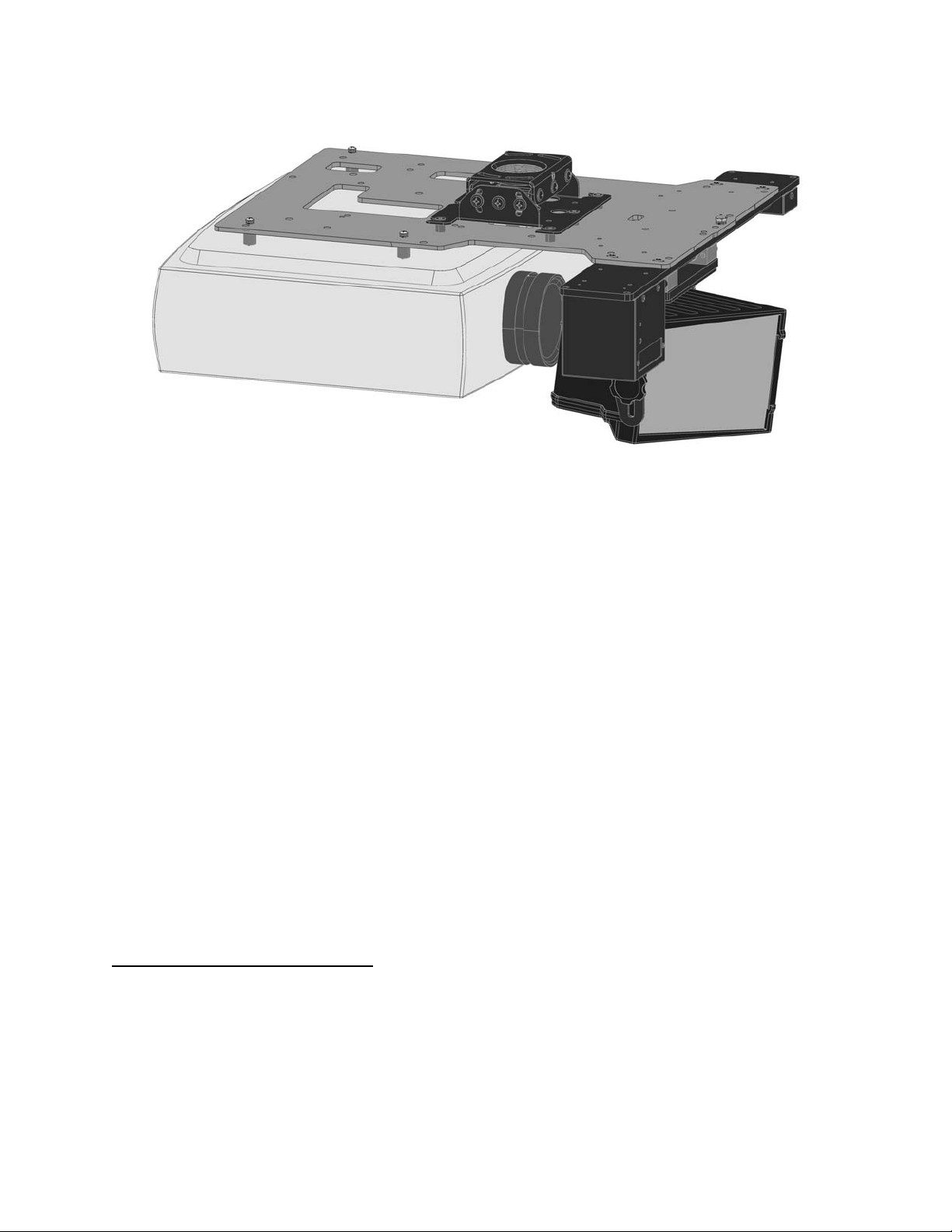
STEP TWO - MOUNT THE MOTORIZED TRANSPORT: Position the flat side of the ATH
Transport against the bottom side (projector side) of the Attachment Plate so that the Transport
connector jacks are toward the projector
and the center “M” hole in the Attachment
Plate is aligned with the front recessed
transport hole. Insert the #10-32 x 5/8
pivot screw up through the Transport and
Attachment Plate and loosely complete
the assembly with the corresponding
washer, lock washer and nut. Now
Motorized Transport
#10-32x5/8” screw (1)
#10-32 lock washer (1)
#10-32 washer (1)
#10-32 nut (1)
P
ivot screw as
assembled
Attachment
Plate
loosely insert the four small 3/8” screws
through the four remaining “M” slots
through the top of the Attachment Plate
#6-32x3/8” screw (4)
Transport
and down into the Transport.
STEP THREE – PREP THE RPA ATTACHMENT SCREWS: Insert a black socket
head screw through a silver 3/8” spacer into each of the six threaded holes in the top of
the Attachment Plate. Insert these screws only enough to reach through to the bottom
of the Attachment Plate.
STEP FOUR – MOUNT THE PROJECTION ASSEMBLY: Ensure that the RPA mount
head is secure and oriented properly relative to the Attachment Plate RPA screws so that the
mounted projector will face the screen. Use two people to lift and position the projection
assembly so that the heads of each of the Attachment Plate RPA screws rest within the
matching final location of the RPA mount head. At this point the silver 3/8” spacers should be
between the Attachment Plate and the RPA mount head. The projection assembly may be
lowered to allow the RPA screw heads to rest on the RPA mount. However, one person should
continue to support the projection assembly while a second person uses the gold hex key
wrench to tighten the RPA screws.
When tightening the RPA screws, do so in a pattern of incrementally driving each screw a little
more into the attachment plate so that at any time the projection assembly is resting on as many
screw heads as possible until all are tightened.
STEP FIVE – INSTALL THE LENS: Refer to the Transport user manual for additional
instructions to install the lens at this time. REMEMBER TO COMPLETE THE LAST STEP
BELOW.
STEP SIX – FINAL ADJUSTMENTS:
a. Turn the projector on with the anamorphic lens out of the projector beam. Set
the horizontal lens shift to neutral and then adjust the RPA mount so that the 16:9 image is in
the exact center of and square to the screen with a similar amount of image slightly over the top
and bottom screen borders. If the projector lens is not in the exact horizontal center of the
screen you may need to use a little horizontal lens shift for this purpose.
b. Bring the anamorphic lens into the beam. Adjust the vertical position and tilt of
the lens so that the projector beam is passing through the center of the lens and so any residual
pincushion distortion is about the same at the top and bottom of the image. This will typically
Page 3
Page 4

result in the Panamorph anamorphic lens being below the center of the projector lens and tilted
slightly downward. Tighten the knobs.
c. Adjust the rotation of the Transport about the Pivot Screw so that the left and
right sides of the image are an equal distance from their respective screen borders. Now
tighten the Pivot Screw and the four #6 screws holding the Transport to the Attachment Plate.
d. For optimum multiple aspect ratio performance, adjust the projector’s zoom so
that a 1.85:1 aspect ratio movie (Panamorph anamorphic lens “out”) is just masked by the top
and bottom of the screen border. This way 1.85:1, 16:9 and 2.35-2.4:1 aspect ratio movies
should all be presented to fill the screen at a constant height.
Note: If you use lens zoom while projecting in anamorphic mode, you may observe a slight image
distortion and reduced brightness. To minimize these effects, place the projector at the recommended
distance from the screen, as listed in your projector manual. This will lessen the need to use lens zoom.
CLEANING
In most applications lenses do not need very much cleaning – a bit of dust will not impact image
clarity. However, in today’s high performance home cinemas with very dark rooms a small
build-up of dust or other foreign matter on the projector lens or Panamorph anamorphic lens can
degrade image quality. Clean the lens whenever you notice dust or dirt on the surface. Use a
blower brush designed for camera equipment to remove dust from the lens. To remove dirt or
smears use a lens cloth or tissue. If necessary, moisten the cloth with lens cleaner and gently
wipe the lens surface. CAUTION: Never rub the lens with abrasive materials. Use only lens
cleaning fluids designed for cleaning optics.
If there is any residue or build-up on the anamorphic lens then it is recommended that you clean
the optics while the anamorphic lens is in front of the lit beam of the projector. This will allow
you to quickly see both the results of cleaning and also if you are causing any damage.
ELPALK2 ATTACHMENT KIT COMPONENTS
ITEM QTY
Attachment Plate 1
5/8” long plastic spacer 5
M4x30mm screw 5
M4 flat washer 5
M4 lock washer 5
#10-24x7/8” socket head screw 6
3/8” long aluminum spacer 6
1/8” Gold hex key 1
#6-32x3/8” screw 4
#10-32x5/8” screw 1
#10-32 nut 1
#10-32 lock washer 1
#10-32 flat washer 1
Instructions 1
Page 4
Page 5

LIMITED WARRANTY
Panamorph, Inc. warrants components in this ELPALK2 kit to be free of defects in original
workmanship and material for a period of two years from the date of manufacture listed on or
inside its shipping container. During this period, a defective unit may be repaired or replaced, at
the discretion of Panamorph, Inc., by returning it in its original packaging with a copy of your
receipt. This warranty does not cover damage resulting from lack of prudent care, accident or
misuse (including the use of motor systems with lenses or other products in ways not intended),
or any cosmetic damage not reported within 15 days of purchase. Damages are limited to the
cost of the product. A service charge may be applied to any returned product requiring
cosmetic attention, or to the repair of any damage not covered under this warranty
CONTACT INFORMATION
Panamorph, Inc.
1880 Office Club Pointe
Suite 3000
Colorado Springs, CO 80920
719-266-2680
www.panamorph.com
Page 5
 Loading...